WO2017065283A1 - Load sensor, load detecting device and seat for sitting - Google Patents
Load sensor, load detecting device and seat for sitting Download PDFInfo
- Publication number
- WO2017065283A1 WO2017065283A1 PCT/JP2016/080570 JP2016080570W WO2017065283A1 WO 2017065283 A1 WO2017065283 A1 WO 2017065283A1 JP 2016080570 W JP2016080570 W JP 2016080570W WO 2017065283 A1 WO2017065283 A1 WO 2017065283A1
- Authority
- WO
- WIPO (PCT)
- Prior art keywords
- electrode
- conductive elastic
- load
- seat
- resistance value
- Prior art date
Links
Images


Classifications
-
- G—PHYSICS
- G01—MEASURING; TESTING
- G01L—MEASURING FORCE, STRESS, TORQUE, WORK, MECHANICAL POWER, MECHANICAL EFFICIENCY, OR FLUID PRESSURE
- G01L1/00—Measuring force or stress, in general
- G01L1/20—Measuring force or stress, in general by measuring variations in ohmic resistance of solid materials or of electrically-conductive fluids; by making use of electrokinetic cells, i.e. liquid-containing cells wherein an electrical potential is produced or varied upon the application of stress
-
- B—PERFORMING OPERATIONS; TRANSPORTING
- B60—VEHICLES IN GENERAL
- B60N—SEATS SPECIALLY ADAPTED FOR VEHICLES; VEHICLE PASSENGER ACCOMMODATION NOT OTHERWISE PROVIDED FOR
- B60N2/00—Seats specially adapted for vehicles; Arrangement or mounting of seats in vehicles
- B60N2/90—Details or parts not otherwise provided for
-
- G—PHYSICS
- G01—MEASURING; TESTING
- G01G—WEIGHING
- G01G19/00—Weighing apparatus or methods adapted for special purposes not provided for in the preceding groups
- G01G19/52—Weighing apparatus combined with other objects, e.g. furniture
-
- G—PHYSICS
- G01—MEASURING; TESTING
- G01G—WEIGHING
- G01G3/00—Weighing apparatus characterised by the use of elastically-deformable members, e.g. spring balances
- G01G3/12—Weighing apparatus characterised by the use of elastically-deformable members, e.g. spring balances wherein the weighing element is in the form of a solid body stressed by pressure or tension during weighing
- G01G3/14—Weighing apparatus characterised by the use of elastically-deformable members, e.g. spring balances wherein the weighing element is in the form of a solid body stressed by pressure or tension during weighing measuring variations of electrical resistance
Definitions
- the present disclosure relates to a load sensor, a load detection device, and a seat for seating.
- the vehicle is provided with a vehicle seat as a seat for seating.
- a cushion material such as urethane foam is used for the cushion pad of the seat cushion and the seat back, and the seat is elastically deformed by a load received from the seated occupant so that the occupant can have a comfortable sitting comfort.
- the vehicle is provided with an occupant protection device such as an air bag device or a seat belt device, and the occupant seated on the vehicle seat is protected by the occupant protection device in the event of a vehicle emergency.
- the vehicle may be provided with a sensor that detects whether or not an occupant is seated on the vehicle seat. Vehicles with occupant detection sensors on the vehicle seat control the operation of the occupant protection device in the event of a vehicle emergency depending on, for example, whether the occupant is seated on the vehicle seat supported by the occupant protection device is doing.
- an electrostatic capacity method As an occupant detection sensor provided in a vehicle seat, an electrostatic capacity method, a method using a strain sensor provided between a vehicle seat and a rail for fixing the vehicle seat to a vehicle body, a seat on which an occupant sits A method using a pressure sensor provided in a cushion has been proposed.
- a detection electrode in which conductors are arranged in a comb shape is provided on the surface of a seat cushion pad, and the capacitance between the detection electrode and the vehicle body caused by a passenger sitting on the seat
- a capacitive-type occupant detection sensor that detects a change in the frequency as an oscillation frequency change by an oscillation circuit.
- the occupant detection sensor provided on the vehicle seat is required to accurately detect the occupant seated on the seat with a simple configuration without affecting the seating comfort of the occupant. Moreover, it is preferable that the occupant detection sensor provided on the vehicle seat can detect the physique of the seated occupant (for example, whether it is an adult or a dwarf).
- This disclosure provides a load sensor and a load detection device capable of detecting a load with a simple configuration.
- the present disclosure also provides a seat for seating that can accurately detect a person's seating and that can detect the physique of the seated person.
- the first aspect of the present disclosure includes (1) a first surface to which a load is input and a second surface opposite to the first surface, and is elastically compressed according to the input load.
- a conductive elastic member that changes an electrical resistance value between the first surface and the second surface; (2) a first electrode provided to face the first surface; and (3) the first surface.
- a second electrode that is provided to face two surfaces and is electrically connected to the first electrode via the conductive elastic member.
- each of the pair of electrodes is opposed to each other with a conductive elastic member having a characteristic that the resistance value decreases by being elastically deformed and compressed according to the load.
- the shape of the conductive elastic member may be a cubic shape, a rectangular parallelepiped shape, or a cylindrical shape, and is not limited to these, and has an arbitrary planar shape and a predetermined height, and is elastic by a load. Various shapes whose height changes by being deformed can be applied.
- a sheet-like electrode having a shape matching the planar shape of the conductive elastic member is applied.
- At least one of the conductive elastic member, the first electrode, and the second electrode as a mesh in which a plurality of openings having a predetermined size are arranged.
- An insulating sheet provided between the first electrode and the second electrode through a part of the conductive elastic member that is elastically compressed and enters each of the plurality of openings. Is a load sensor that can be electrically connected to each other.
- the insulating sheet has a mesh shape in which openings of a predetermined size are arranged.
- the insulating sheet is provided between at least one of the first electrode and the second electrode and the conductive elastic member. For this reason, for example, when the insulating sheet is disposed between the first electrode and the conductive elastic member, the first electrode is removed from the conductive elastic member when no load is input to the conductive elastic member. Since it leaves
- the first electrode and the second electrode are electrically connected via the conductive elastic member, and the electric resistance value generated in the conductive elastic member and the contact area between the conductive elastic member and the first electrode are increased. A corresponding electrical resistance value is detected.
- the electrical resistance value is lowered by compressing the conductive elastic member, and the electrical resistance value is lowered by increasing the contact area between the conductive elastic member and the first electrode. Therefore, the electrical resistance value between the first electrode and the second electrode changes greatly between the state in which no load is input to the conductive elastic member and the state in which the load is input, and the load is applied to the conductive elastic member. Whether it is input or not can be detected with high accuracy.
- the change in the electrical resistance value between the first electrode and the second electrode with respect to the change in the input load is greater than when no insulating sheet is provided, the input load is highly accurate. Can be detected.
- the insulating sheet is provided with a plurality of small holes having an opening smaller than the opening around each of the plurality of openings. It is a load sensor in which the first electrode and the second electrode can be electrically connected through a part of the conductive elastic member that enters each of the plurality of small holes by being elastically compressed.
- a plurality of small holes that are smaller than the opening are formed in the insulating sheet.
- the conductive elastic member enters the small hole of the insulating sheet.
- the conductive elastic member and the first electrode (or the second electrode) are connected via the opening and the small hole opened smaller than the opening by further increasing the load input to the conductive elastic member. Therefore, the contact area of the first electrode (or the second electrode) that contacts the conductive elastic member increases.
- the electrical resistance value between the first electrode and the second electrode decreases according to the displacement of the conductive elastic member and the increase in the contact area of the first electrode (or the second electrode). It changes more greatly than the electrical resistance value corresponding only to the displacement of the member.
- the first electrode and the second electrode Since the change of the electrical resistance value between the first electrode and the second electrode is added to the displacement of the electrical resistance value of the conductive elastic member according to the input load, the first electrode and the second electrode The range in which the load input to the conductive elastic member can be detected with high accuracy from the electric resistance value between them is widened.
- the fourth aspect further includes a stretchable sheet disposed to face the first surface of the conductive elastic member, and the first electrode includes: It is a load sensor formed by sewing a conductive thread into the stretchable sheet.
- the stretchable sheet is provided so as to face one surface of the conductive elastic member, and the first electrode is provided by being sewn into the stretchable sheet.
- the first electrode By providing the first electrode on the stretchable sheet, the first electrode expands and contracts following the elastic deformation of one surface of the conductive elastic member, and can be electrically connected to the conductive elastic member.
- conductive yarn is used.
- the conductive yarn has conductivity
- the first electrode is formed by sewing the conductive yarn into the stretchable sheet. Since the conductive yarn is intermittently held on the stretchable sheet at the seam, it is possible to prevent the stretchability of the stretchable sheet from being impaired.
- a fifth aspect of the present disclosure includes a load including the load sensor according to the first to fourth aspects, and a detection unit that detects an electrical resistance value between the first electrode and the second electrode. It is a detection device.
- each of the pair of electrodes is connected to the detection means, and the resistance value between the pair of electrodes is detected by the detection means.
- a sixth aspect of the present disclosure is the load detection device according to the fifth aspect, in which the detection unit determines the load from the electric resistance value.
- the load detection device determines the load that is elastically deforming the conductive elastic member from the resistance value between the pair of electrodes.
- the load may be determined by determining the load value corresponding to the resistance value, and when the load is divided into a plurality of levels according to the magnitude, the load that elastically deforms the conductive elastic member However, it may be determined which level is supported.
- a seventh aspect of the present disclosure is a seat for seating provided with the load sensors according to the first to fourth aspects, wherein the conductive elastic member is provided on a cushion pad of the seat cushion, and the first aspect is provided.
- the seat is a seat for which a surface is an upper surface of the cushion pad and the second surface is a lower surface of the cushion pad.
- the conductive elastic member is provided on the cushion pad.
- the conductive elastic member provided on the cushion pad is preferably formed with a thickness corresponding to the thickness of the cushion pad, may form part of the cushion pad, and the cushion pad may be formed of the conductive elastic member. It may be formed so that the conductive elastic portion becomes a cushion pad.
- the conductive elastic member of the seating sensor is provided on the cushion pad of the seat cushion.
- the region where the conductive elastic member is provided only needs to include a region that receives a load from the seated person, so that when the person sits on the seat cushion, the load according to the physique (weight) of the seated person is conducted.
- the conductive elastic member is elastically deformed by being input to the conductive elastic member.
- a person can enter the seat cushion from the electric resistance value between the first electrode and the second electrode. Whether the person is seated or the physique of the person who is seated can be detected.
- the stretchable sheet provided with the first electrode is disposed on the upper surface side of the conductive elastic member, and the conductive elastic member It is expanded and contracted according to the deformation of the upper surface.
- the 1st electrode provided in the elastic sheet does not impair the sitting comfort of the person seated on the seat cushion.
- the physique (weight) of the occupant seated on the seat cushion can be detected with high accuracy as the load input to the conductive elastic member.
- the first electrode and the second electrode are connected to a detection unit that detects an electrical resistance value between the first electrode and the second electrode. This is a seat for seating.
- the detection means since the detection means detects the resistance value between the first electrode and the second electrode, the load that elastically deforms the conductive elastic member from the resistance value detected by the detection means. Can gain the weight of the person.
- a ninth aspect of the present disclosure is the seat for seating according to the eighth aspect, wherein the detection means outputs a load input to the seat cushion based on the detected electric resistance value.
- the detection means detects the electrical resistance value between the first electrode and the second electrode.
- the detecting means determines and outputs the load input to the seat cushion from the electrical resistance value between the first electrode and the second electrode.
- the detection means accurately determines the physique of the occupant seated on the seat cushion from the detected electric resistance value. Can output well.
- a tenth aspect of the present disclosure is the seat for seating according to the seventh to ninth aspects, wherein the cushion pad is formed of urethane foam, and the conductive elastic member is formed of conductive urethane foam.
- a conductive elastic member formed of conductive urethane foam is provided on a cushion pad formed of urethane foam.
- Such a seat for seating according to the present disclosure can be applied as a vehicle seat provided in a vehicle such as an automobile.
- the seat for seating is not limited to a seat for a vehicle, but is used for seating a person such as a seat provided in an aircraft or a ship, a seat provided in an attraction of a game facility, or a seat provided in an entertainment facility such as a movie theater. It can be applied to various seats with cushioning properties.
- the load sensor and the load detection device can detect the magnitude of the load with a simple configuration in which the pair of electrodes are brought into contact with the conductive elastic portion.
- the seat for seating of the present disclosure enables detection of whether a person is seated and whether the seated person is an adult or a child without impairing the sitting comfort.
- a conductive elastic member is provided by disposing a mesh-like insulating sheet in which a plurality of openings are arranged between one of the first electrode and the second electrode and the conductive elastic member. It is possible to properly detect whether or not a load is input to the.
- the first sheet and the second electrode with respect to the displacement of the conductive elastic member can be provided by providing the insulating sheet with a plurality of small holes that are smaller than the opening, around the opening. Since the change in electrical resistance value between the two electrodes can be increased, the range of loads that can be detected with high accuracy is widened.
- FIG. 1 is a schematic perspective view of a vehicle seat according to the present disclosure. It is a schematic sectional drawing along the width direction of the principal part of the seat cushion concerning this indication, and has shown the state where the load is not received. It is a schematic sectional drawing along the width direction of the principal part of the seat cushion concerning this indication, and shows an example of the state which received the load. It is a block diagram of the seating sensor which concerns on 1st Embodiment of this indication, and has shown the state which has not received the load. It is a lineblock diagram of a seating sensor concerning a 1st embodiment of this indication, and shows an example of a state which received load.
- FIG. 7A It is a diagram which shows the outline of the change of the resistance value with respect to the compression amount of the electroconductive elastic part which concerns on 1st Embodiment of this indication. It is a schematic block diagram of the passenger
- FIG. 1 shows a vehicle seat 10 as a seat for seating according to the present embodiment.
- the vehicle seat 10 is provided in a vehicle such as a passenger car and is used for seating a passenger of the vehicle.
- the front side in the longitudinal direction of the seat is indicated by an arrow FR
- the width direction of the seat is indicated by an arrow W
- the upper side in the vertical direction of the seat is indicated by an arrow UP.
- the vehicle seat 10 includes a seat cushion 12, a seat back 14, and a headrest 16.
- a slide mechanism including a pair of left and right slide rails 18 is fixed to the vehicle body.
- a cushion frame (not shown) that forms a skeleton of the seat cushion 12 is stretched around the slide rail 18.
- the seat 10 for vehicles is supported by the slide rail 18, the vehicle seat 10 is movable to the vehicle front-back direction, and is fixed to a movement position.
- a seat back frame (not shown) that forms a skeleton of the seat back 14 is connected to the cushion frame via a reclining mechanism (not shown) on the rear side of the seat cushion 12.
- the vehicle seat 10 is supported so that the seat back 14 can move to the slide rail 18 integrally with the seat cushion 12 and can be tilted.
- the headrest 16 is integrally formed with the seat back 14 at the upper end portion of the seat back 14.
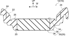
- FIG. 2A and FIG. 2B show schematic cross sections of main portions of the seat cushion 12 of the vehicle seat 10 cut along the width direction.
- 2A shows a state where no occupant is seated
- FIG. 2B shows an example of a state where the occupant is seated.
- the seat cushion 12 includes a cushion pad 20, and the surface of the cushion pad 20 is covered with a skin material 22.
- the vehicle seat 10 has a general configuration in which a cushion pad (not shown) of the seat back 14 and the headrest 16 is covered with a skin material 22.
- the cushion pad 20 of the seat cushion 12 has, for example, convex portions formed on both sides in the width direction, and a flat portion is formed between the convex portions.
- the vehicle seat 10 is a side support portion 24 in which convex portions on both sides in the width direction of the seat cushion 12 are opposed to the side of the thigh of the occupant.
- the flat portion is a seat portion 26 on which an occupant is seated.
- the vehicle seat 10 has the cushion pad 20 made of a material, cushioning properties, elastic characteristics and the like so that an occupant seated on the seat cushion 12 can have a comfortable sitting comfort and a comfortable riding comfort.
- the seat portion 26 of the seat cushion 12 is applied with a load according to the physique and weight of the seated occupant, and the cushion pad 20 is elastically deformed.
- urethane foam soft urethane foam, foamed urethane
- urethane foam is applied as an example of an elastic member that forms a cushion pad of the vehicle seat 10.
- FIGS. 3A and 3B show a schematic configuration of an occupant detection device 28 as a load detection device according to the present embodiment.
- the occupant detection device 28 includes a seating sensor 30 that detects the seating of the occupant on the vehicle seat 10 and an ECU (Electronic Control Unit) 32.
- the seating sensor 30 functions as an example of a load sensor
- the ECU 32 functions as an example of a detection unit. That is, in the present embodiment, the load sensor is applied to the seating sensor 30 of the vehicle seat 10.
- the seating sensor 30 includes an electrode 34 and an electrode 36 as a pair of electrodes.
- the electrodes 34 and 36 function as a pair of electrodes
- the electrode 34 functions as an example of a first electrode
- the electrode 36 functions as an example of a second electrode.
- the electrodes 34 and 36 are provided corresponding to a region where a load is applied from an occupant seated on the vehicle seat 10. That is, in the vehicle seat 10, the seat portion 26 of the seat cushion 12 mainly receives a load from the occupant's buttocks. Thus, in the present embodiment, as an example, the electrodes 34 and 36 are disposed on the seat back 14 side of the seat portion 26 corresponding to the occupant's buttocks.
- the electrode 34 is disposed in close contact with the upper surface of the cushion pad 20, and is electrically connected to the cushion pad 20 that is in contact therewith.
- the electrode 34 is covered with the cushion pad 20 by the skin material 22.
- the electrode 34 is formed to have elasticity.
- the electrode 34 is formed into a sheet shape by using a stretchable fabric such as spandex made of polyurethane elastic fiber and weaving a conductor into the stretchable fabric.
- the electrode 34 expands and contracts following the deformation of the surface of the cushion pad 20.
- the electrode 34 may be any sheet-like and stretchable structure, and may be formed in a conductive mesh shape, for example.
- the electrode 36 is disposed in close contact with the lower surface of the cushion pad 20, and is electrically connected to the cushion pad 20 in contact therewith.
- a conductor formed in a sheet shape is used for this electrode 36.
- the electrode 36 may be formed into a sheet shape by weaving a conductive material into a stretchable fabric, like the electrode 34, but is not limited thereto, and a general material using a metal that does not have stretchability is used.
- the target electrode can be applied.
- the electrode 36 may have a smaller contact area than the electrode 34, for example, may be a point electrode, or a cushion frame using a conductive metal may be applied as the electrode 36.
- a conductive elastic portion 38 using a conductive elastic member is formed at a portion between the electrodes 34 and 36.
- urethane foam soft urethane foam
- a conductive urethane foam in which the urethane foam used for the cushion pad 20 is made conductive is used as an example of the conductive elastic member that forms the conductive elastic portion 38.
- urethane foam functions as an electrical insulator and has an extremely high electrical resistance (for example, a volume resistivity of 10 11 ⁇ m or more).
- the conductive urethane foam used for the conductive elastic portion 38 is obtained by, for example, supporting urethane carbon with conductive carbon particles such as carbon black. By containing conductive carbon particles such as carbon black, urethane foam The electrical resistance (for example, the volume resistivity is 10 7 ⁇ m or less) is lowered.
- the conductive urethane foam is compressed according to the load received by receiving the load, and the electrical resistance value becomes smaller than the case where the conductive urethane foam is not compressed by being compressed. That is, the conductive urethane foam has a characteristic that the resistance value becomes small according to the compression amount.
- Conductive urethane foam is widely used as a protective packaging material for electronic parts, an electronic shielding material, and the like.
- the conductive urethane foam is used for the conductive elastic portion 38 provided between the electrodes 34 and 36 of the seating sensor 30.
- the conductive urethane foam according to this embodiment is manufactured by supporting conductive carbon particles such as carbon black on a urethane foam using a known method applied to the production of these conductive urethane foams. Applicable.
- the conductive urethane foam is not limited to the one using conductive carbon particles such as carbon black, and one obtained by imparting conductivity to the urethane foam by any method can be applied.
- the entire cushion pad 20 used for the seat cushion 12 may be foam-molded so as to be conductive.
- the conductive urethane foam may be fitted only in the corresponding part.
- the portion corresponding to the conductive elastic portion 38 is formed from the seat portion 26 of the cushion pad 20 formed of urethane foam. Cut out, and an opening corresponding to the conductive elastic portion 38 is formed in the cushion pad 20 and a block of urethane foam corresponding to the opening is formed. Thereafter, the urethane foam block is subjected to a treatment for providing conductivity, thereby forming the conductive elastic portion 38, and the formed conductive elastic portion 38 is fitted into the opening of the cushion pad 20. As a result, the cushion pad 20 in which the conductive elastic portion 38 is disposed at a portion corresponding to the electrodes 34 and 36 is obtained.
- the cushion pad 20 in which the conductive urethane foam is fitted in the portions corresponding to the electrodes 34 and 36 is obtained, for example, the seat 26 of the cushion pad 20 formed of urethane foam corresponds to the conductive elastic portion 38. A part is cut out, and an opening corresponding to the conductive elastic portion 38 is formed in the cushion pad 20. Separately from the cushion pad 20, a urethane foam block having a shape corresponding to the opening is formed on the cushion pad 20, and the formed urethane foam block is subjected to a treatment to make it conductive. The elastic elastic portion 38 is formed, and the formed conductive elastic portion 38 is fitted into the opening of the cushion pad 20. Even if this method is used, the cushion pad 20 in which the conductive elastic portion 38 is disposed at the portion corresponding to the electrodes 34 and 36 is obtained.
- the occupant detection device 28 has electrodes 34 and 36 of a seating sensor 30 connected to the ECU 32.
- the ECU 32 detects the resistance value R between the electrodes 34, 36, that is, the resistance value R of the conductive elastic portion 38. Since the resistance value (resistance value R) of the compressed conductive elastic portion 38 is lower than the resistance value of the conductive elastic portion 38 in the non-compressed state (hereinafter referred to as resistance value R0), the resistance of the electrodes 34 and 36 is reduced. From the value R, it is detected whether or not the conductive elastic portion 38 receives a load, that is, whether or not an occupant is seated on the vehicle seat 10.
- the ECU 32 determines that the occupant seated on the vehicle seat 10 is an adult who is a dwarf from the detected resistance value R. Determine if there is.
- the vehicle seat 10 When the occupant is seated on the vehicle seat 10, the occupant is seated with the buttocks supported by the seat cushion 12 and the back supported by the seat back 14.
- the vehicle seat 10 is elastically deformed by a load that the cushion pad 20 of the seat cushion 12 receives from the occupant's buttocks.
- crew who seated on the vehicle seat 10 can obtain a comfortable seating feeling, for example.
- the seat cushion 12 is provided with a conductive elastic portion 38 on the seat portion 26 of the cushion pad 20, and the conductive elastic portion 38 is elastically deformed and compressed in accordance with the weight (load) received from the occupant when the occupant is seated.
- the load is removed due to (volume compression) and the occupant stands up, the original volume is restored.
- the electrodes 34 and 36 are electrically connected to the conductive elastic portion 38 using conductive urethane foam, so that the electrode 34 and the electrode 36 are connected to the conductive elastic portion 38.
- the connection is made through a resistor having a resistance value R determined according to the thickness and the area of the electrodes 34 and 36 (contact area to the conductive elastic portion 38).
- the conductive elastic portion 38 when the load is applied, the conductive elastic portion 38 is elastically deformed and compressed according to the applied load. When the conductive elastic portion 38 is compressed and becomes thin, the resistance value R decreases.
- the ECU 32 to which the seating sensor 30 is connected detects the resistance value R between the electrodes 34 and 36 that changes due to the load received by the conductive elastic portion 38.
- the conductive elastic portion 38 is D0 (see FIG. 3A) when the conductive elastic portion 38 is in a non-compressed state, and D1 (see FIG. 3B) when the conductive elastic portion 38 is compressed under a load, the load is received.
- FIG. 4 shows an outline of a change in the resistance value R of the conductive elastic portion 38 with respect to the compression amount C.
- the resistance value R of the conductive elastic portion 38 decreases as the input load increases and the compression amount C increases. Accordingly, in the seating sensor 30, the resistance value R between the electrodes 34 and 36 changes according to the compression amount C of the conductive elastic portion 38, that is, the load input to the conductive elastic portion 38, and the load increases. As the resistance value R decreases.
- the ECU 32 determines the weight of the occupant seated on the vehicle seat 10 from the detected resistance value R.
- the determination of the weight of the occupant is performed by, for example, measuring the weight of the occupant seated on the vehicle seat 10 and the resistance value R corresponding to the weight in advance, thereby defining a characteristic curve or map of the resistance value with respect to the weight and storing it in the ECU 32. Keep it.
- the ECU 32 determines the approximate weight of the occupant seated on the vehicle seat 10 from the detected resistance value R, and outputs the determination result.
- the weight differs between an adult (for example, an age of 12 years or older) and a child (dwarf, for example, an age of 6 years or more and less than 12 years), and even an adult has a different weight depending on the physique. From here, based on the resistance value R, the physique of the passenger seated on the vehicle seat 10 may be determined.
- the resistance value R when an adult is seated is smaller than the resistance value R when a dwarf is seated. Further, even for an adult, the resistance value R is smaller when a large (heavy) adult is seated than a small (light) adult.
- a threshold value in a plurality of stages may be set for the resistance value R.
- the threshold value Rt1 or less, the threshold value Rt2 or more is a small person, the threshold value Rt2 or less, the threshold value Rt3 or more is an adult having a physique smaller than the average physique, the threshold value Rt3 or less
- the threshold Rt4 or higher is set to be classified as an adult of average physique, less than the threshold Rt4, and the threshold Rt5 or higher is classified as an adult having a larger physique than the average physique.
- less than threshold value Rt5 may be included in an adult with a large physique, and may be classified as an adult with a very large physique.
- the ECU 32 determines the approximate weight of the occupant seated on the vehicle seat 10 from the detected resistance value R, and outputs the determination result.
- an infant restraint device CRS: Child Restorant System, hereinafter referred to as a child seat
- an infant assist device is attached to the vehicle seat 10.
- the resistance value R detected by the ECU 32 becomes smaller than the resistance value R0 when the child seat is attached to the vehicle seat 10, and the resistance value R further decreases when the infant is placed on the child seat.
- the ECU 32 detects a change in the resistance value R by an incorporated algorithm, the ECU 32 may determine that an infant is placed on the vehicle seat 10 and output the detected result.
- the vehicle seat 10 Appropriate protection for passengers seated in the vehicle is possible.
- one electrode 34 is disposed in the conductive elastic portion 38.
- one electrode 34 is divided into a plurality of small electrodes by dividing it vertically and horizontally. And a plurality of small electrodes are arranged in a matrix on the conductive elastic portion 38, or one electrode 34 is divided into a plurality of small electrodes and the conductive elastic portion 38 corresponds to each of the small electrodes. And may be divided.
- an insulating material non-conductive elastic member, for example, a sheet-like urethane foam
- a cushioning property equivalent to that of the conductive elastic portion 38 is provided between the divided conductive elastic portions 38.
- the ECU 32 is connected to a plurality of divided small electrodes separately. When the electrode 36 is divided, the ECU 32 may detect the resistance value between each of the small electrodes and the electrode 36 in order so as to scan vertically and horizontally. In addition, when the conductive elastic portion 38 is divided and an insulation is interposed between the divided conductive elastic portions 38, the ECU 32, for example, sets the resistance value between each of the small electrodes and the electrode 36 in parallel. And then detect it.
- the ECU 32 can obtain whether or not the occupant is seated on the vehicle seat 10 and the load distribution received from the seated occupant in addition to the occupant when the occupant is seated. Such load distribution can be applied to determination of the physique of a seated passenger.
- the seating sensor 30 as a load sensor was arrange
- the attachment position of a load sensor is not restricted to this.
- a load sensor having the same configuration as the seating sensor 30 may be provided at a position corresponding to the back of the occupant.
- An occupant seated on the vehicle seat 10 applies a load to the seat back 14 from the back by sudden acceleration of the vehicle. From here, the load which the seat back 14 receives from a passenger
- the occupant detection device 128 according to the second embodiment of the present disclosure is disposed on the seat cushion 12 of the vehicle seat 10 in the same manner as the occupant detection device 28 of the first example shown in FIGS. However, in the occupant detection device 128 according to the second embodiment, the electrode part 134 is different from the electrode 34 of the occupant detection device 28 in the first embodiment.
- FIG. 5 is a schematic configuration diagram illustrating an occupant detection device 128 according to the second embodiment of the present disclosure.
- the occupant detection device 128 is provided with a seating sensor 130 as a load sensor in place of the seating sensor 30 of the first embodiment, and an ECU 32 as a load output unit.
- the seating sensor 130 is provided with an electrode part 134 provided with a first electrode, an electrode 36 as a second electrode, and a conductive elastic part 38 using a conductive elastic member.
- the electrode part 134 and the electrode A conductive elastic portion 38 is disposed between the conductive elastic portion 38 and the conductive elastic portion 38.
- a conductive metal material such as iron or aluminum is applied to the electrode 36.
- the electrode 36 has an arbitrary shape that can be electrically connected to the conductive elastic portion 38.
- a metal plate such as iron having a thickness of about 0.3 mm to 1.0 mm can be formed into a pan shape (flat plate shape, concave shape) by press forming.
- the electrode 36 may be applied with a mesh shape (punching metal) in which perforations having a predetermined shape are uniformly formed in a press-formed metal plate.
- the vehicle seat 10 is provided with a metallic seat pan below the seat cushion 12, and the seat pan contacts the lower surface of the cushion pad 20 to support the cushion pad 20.
- a sheet pan can be used for the electrode 36, and in the present embodiment, a sheet pan is used for the electrode 36.
- the electrode 36 is not limited to a sheet pan as long as it is electrically connected to the lower surface of the conductive elastic portion 38, and a sheet carrying a conductor or a general electrode using metal is applied. be able to. Further, even if the cushion frame is not provided with a seat pan, when the cushion frame is made of metal, the electrode 36 may be a cushion frame.
- the electrode part 134 of the seating sensor 130 is provided with an electrode sheet 40 and an insulating sheet 42 as an insulating sheet.
- the insulating sheet 42 is disposed on the conductive elastic part 38 side, and the electrode sheet 40 is superimposed on the insulating sheet 42.
- the electrode sheet 40 and the insulating sheet 42 cover the upper surface of the conductive elastic portion 38 in a region where the seat cushion 12 receives a load from the occupant.
- the insulating sheet 42 is made of a sheet that has insulating properties such as an insulating resin film, a woven fabric, and a knitted fabric, and is stretchable and formed in a mesh shape.
- FIG. 6A shows a plan view of an insulating sheet 42 using a woven fabric as an example
- FIG. 6B shows an enlarged view of a main part of the insulating sheet 42 shown in FIG. 6A.
- a tulle mesh (trade name manufactured by Toray, model number # 2070) that is a woven fabric using polyester fibers is shown
- the white portion shows fibers (woven yarn),
- the black part has shown the space
- the insulating sheet 42 is formed in a mesh shape by providing openings as openings (hereinafter referred to as openings 44) arranged vertically and horizontally.
- openings 44 openings as openings
- the size (size) of openings formed by arranging wire rods (woven yarns) vertically and horizontally is represented by the interval (opening width) between the vertical and horizontal wire rods.
- the opening ratio ⁇ is obtained from the thickness of the wire and the opening width of the openings.
- the diameter (inner diameter IDa) of the inscribed circle 46 of the opening 44 is used as the size of the opening 44 (size of the opening).
- the opening ratio ⁇ of the opening 44 (hereinafter referred to as the opening ratio ⁇ 1) is the ratio of the total area of openings (opening 44) per unit area (1 square inch) (the area of the opening 44 relative to the unit area). %) Is applied.
- the insulating sheet 42 has a thickness of 20 ⁇ m to 2.0 mm in a portion excluding the opening 44 and the following small hole 44A.
- the insulating sheet 42 is provided with a plurality of small holes 44A as small holes, and each of the small holes 44A is opened around the opening 44 smaller than the opening 44.
- the size of the opening of the small hole 44A is indicated by the diameter (inner diameter IDb) of an inscribed circle 46A that is a circle in contact with the peripheral edge of the opening similarly to the opening 44.
- the inscribed circles 46 and 46A are the circles having the largest diameter among the circles in contact with at least two points on the periphery in each of the opening 44 and the small hole 44A.
- the insulating sheet 42 has an inner diameter IDb of an inscribed circle 46A of the small hole 44A and an opening ratio ⁇ (hereinafter referred to as an opening ratio ⁇ 2) of the small hole 44A per unit area (1 square inch).
- the aperture ratio ⁇ 2 of the small hole 44A is a percentage of the total area (opening area) of the small hole 44A with respect to the unit area, and the area of the portion other than the small hole 44A includes the area of the opening 44.
- an insulating sheet having a thickness, an inner diameter IDa of the opening 44, and an opening ratio ⁇ of the opening 44 according to the outer diameter of the following electrode yarn 50 is used within the above range.
- an insulating sheet having a thickness, an inner diameter IDb of the small hole 44A, and an opening ratio ⁇ of the small hole 44A according to the outer diameter of the electrode yarn 50 described below is used.
- the fiber yarn (woven yarn) forming the woven fabric and the knitted fabric is a synthetic fiber (resin) such as nylon (may be nylon 6 or nylon 66) fiber or polyester fiber. Fiber).
- the insulating sheet 42 can be made of synthetic fibers such as polyolefin fibers such as polyethylene (PE) and polypropylene (PP).
- PE polyethylene
- PP polypropylene
- the insulating sheet 42 is woven or knitted so that the openings 44 and the plurality of small holes 44A are formed by these synthetic fiber yarns or yarns formed by twisting synthetic fibers. At this time, the stretchability of the insulating sheet 42 is improved by weaving the yarn so that the small holes 44A are continuous in a chain.
- the electrode sheet 40 is formed by a base 48 as a stretchable sheet and an electrode thread 50 as a conductive thread forming the first electrode.
- 7A is a plan view of the main part of the electrode sheet 40
- FIG. 7B is a cross-sectional view of the main part of the electrode sheet 40 shown in FIG. 7A along the sewing direction of the electrode thread 50. It is shown.
- the electrode sheet 40 is a sheet in which the base 48 has stretchability and insulation, and the base 48 preferably has a stretch rate of 130% or more, and a fabric (cloth) such as spandex. ) And resin films are applied.
- a spandex having an expansion ratio equal to or greater than that of the skin material 22 of the seat cushion 12 is used as an example of the substrate 48.
- the electrode yarn 50 is formed by vapor-depositing a conductive metal on a fiber yarn, and conductivity is imparted by the metal vapor-deposited on the fiber yarn. Natural fibers may be used for the fiber yarns, but artificial fibers are preferable because metal deposition is performed, and synthetic fibers (resin fibers) such as polyester fibers are applied.
- the electrode yarn 50 is formed by twisting a plurality of (for example, two or three) fiber yarns, and the wire diameter (outer diameter) is in a range of 0.1 mm to 1.0 mm by metal deposition. Can be used.
- the alloy etc. which were formed by combining arbitrary metals, such as silver (Ag), gold
- the outer diameter of the electrode yarn 50 and the sizes of the opening 44 and the small hole 44A of the insulating sheet 42 are associated with each other.
- the insulating sheet 42 is provided with an opening 44 in which the inner diameter IDa of the inscribed circle 46 is at least larger (including slightly larger) than the outer diameter of the electrode yarn 50, and the inner diameter IDa of the inscribed circle 46 is provided. Is more preferably provided with an opening 44 that is twice or more the outer diameter of the electrode yarn 50.
- the insulating sheet 42 is provided with a plurality of small holes 44A in which the inner diameter IDb of the inscribed circle 46A is smaller than the inner diameter IDa of the opening 44, and the inner diameter IDb of the inscribed circle 46A is an electrode thread. It is approximately the same as or slightly smaller than the outer diameter of 50. That is, the small hole 44 ⁇ / b> A has an inner diameter IDb that is equal to or smaller than the outer diameter of the electrode yarn 50.
- an electrode thread 50 is sewn into the base 48 and arranged.
- Arbitrary patterns can be applied to the wiring of the electrode yarn 50 to the substrate 48, but the area of the electrode yarn 50 appearing on the insulating sheet 42 side is large (long) and the stretchability of the substrate 48 is impaired. A pattern with no is preferred.
- FIG. 7A shows an example of the pattern of the electrode yarn 50 arranged on the substrate 48 in a plan view viewed from the insulating sheet 42 side.
- 7B is a cross-sectional view of the main part of FIG.
- a staggered pattern 52 is applied as a pattern (stitch pattern) for sewing the electrode thread 50 into the substrate 48.
- the staggered pattern 52 is obtained by alternately sewing the electrode threads 50 on the left and right sides around the wiring 54 with respect to the virtual wiring 54 along the sewing direction of the electrode thread 50. Yes. That is, the staggered pattern 52 is so-called zigzag stitching that is zigzag stitched so that the electrode threads 50 (stitches of the electrode threads 50) intersect the wiring 54.
- the base 48 may be sewn with the electrode thread 50 on both the left and right sides of the wiring 54. Instead of scooping the base 48 with the electrode thread 50, the electrode thread 50 may be sewn with the base 48. You may be allowed to pass through. Further, when one electrode yarn 50 is inserted, the length of the electrode yarn 50 that appears on the insulating sheet 42 side of the substrate 48 is shortened. From here, the two electrode yarns 50 may be used, and the two electrode yarns 50 may be sewn into the substrate 48 so as to alternately appear on the insulating sheet 42 side.
- the gap between the stitches of the electrode thread 50 appearing on the insulating sheet 42 side can be continuously formed without opening, the length of the electrode thread 50 on the insulating sheet 42 side can be increased, and the insulating sheet 42 side The surface area of the electrode yarn 50 can be increased.
- an electrode thread 50 and a non-conductive thread (hereinafter referred to as a locking thread 50A) are used.
- the locking yarn 50A any yarn can be used, and the fiber yarn before metal vapor deposition used for the electrode yarn 50 can be used.
- the electrode yarn 50 is routed on one surface of the substrate 48, and the locking yarn 50A is routed on the other surface.
- the electrode thread 50 sewn into the substrate 48 is sewed together by the locking thread 50A sewn into the substrate 48 from the opposite side of the electrode thread 50, so that the electrode thread 50 and the locking thread 50A are sewn into the substrate 48.
- the electrode yarn 50 is routed on one surface of the substrate 48, and the locking yarn 50 ⁇ / b> A is routed on the other surface of the substrate 48.
- the electrode yarn 50 and the engagement yarn 50A are held on both the left and right sides of the routing wire 54 so that the electrode yarn 50 is wound.
- the stop yarns 50 ⁇ / b> A may be locked to the substrate 48.
- the electrode yarn 50 is used to squeeze the locking yarn 50A on both the left and right sides of the wiring 54.
- the electrode yarn 50 and the locking yarn 50A may be locked to the substrate 48.
- the staggered pattern 52 has a stitch interval ND and a stitch width NW that are set so that the stretchability of the substrate 48 is not impaired and the length of the electrode yarn 50 that appears on the insulating sheet 42 side is increased. It is determined and formed on the substrate 48.
- the staggered pattern 52 is applied as a pattern for arranging the electrode yarns 50, so that the vertical and horizontal stretchability of the substrate 48 into which the electrode yarns 50 are sewn can be prevented from being impaired.
- the electrode thread 50 is sewn into a region of the substrate 48 (for example, substantially the entire region of the substrate 48) corresponding to a region where a load is input to the conductive elastic portion 38.
- an electrode network as a first electrode is formed on the substrate 48.
- FIG. 8A and FIG. 8B are plan views showing an example of an electrode network applicable in the present embodiment.
- straight wiring lines 54A and 54B are set in a lattice form vertically and horizontally at a predetermined stitch interval SD.
- the electrode thread 50 is sewn by the staggered pattern 52 along each of the plurality of wirings 54 ⁇ / b> A and 54 ⁇ / b> B.
- a plurality of wiring lines 54C each having a different radius are set concentrically.
- a plurality of straight wiring lines 54D are set radially from the center position of the wiring line 54C.
- the electrode yarns 50 are routed by being sewn by the staggered pattern 52 along each of the routing lines 54C and 54D.
- the stitch interval SD is set together with the stitch width NW and the stitch interval ND of the staggered pattern 52 so that the electrode threads 50 are evenly arranged in a predetermined region to form the electrode nets 56 and 58. Is done.
- the electrode yarn 50 faces or is adjacent to part or all of the openings 44 of the insulating sheet 42, and the electrode yarn 50 faces or is adjacent to part or all of the small holes 44 ⁇ / b> A.
- an electrode network 56 is formed on the electrode sheet 40 as an example of the first electrode.
- the electrode sheet 40 may be formed with an electrode network having a combination of the electrode networks 56 and 58, such as disposing the electrode network 56 around the outer periphery of the electrode network 58.
- the electrode sheet 40 may be formed with an electrode network in the form of an oblique lattice in which each of the straight wiring lines 54A and 54B is inclined.
- an insulating sheet 42 having elasticity is disposed on the conductive elastic portion 38, and the electrode sheet 40 is overlapped on the insulating sheet 42, so that the conductive elasticity is passed through the electrode sheet 40 and the insulating sheet 42.
- a load is input to the portion 38.
- the insulating sheet 42 is brought into close contact with the upper surface of the conductive elastic portion 38, and the electrode sheet 40.
- the electrode yarn 50 is brought into close contact with the insulating sheet 42.
- the electrode yarns 50 arranged on the electrode sheet 40 of the seating sensor 130 are collectively connected and electrically connected to the ECU 32.
- the ECU 32 can detect the resistance value between the electrode part 134 and the electrode 36 by electrically connecting the electrode part 134 and the electrode 36 to the conductive elastic part 38.
- the resistance value between the electrode portion 134 and the electrode 36 detected by the ECU 32 changes according to the thickness displacement amount when the conductive elastic portion 38 is elastically deformed, and is detected as the displacement amount increases. The resistance value becomes lower.
- the resistance value detected by the ECU 32 changes according to the contact area of the electrode yarn 50 of the electrode part 134 that is in contact with the conductive elastic part 38, and becomes lower than when the contact area is widened.
- the ECU 32 measures the displacement of the conductive elastic portion 38 with respect to the load and the resistance value between the electrode portion 134 and the electrode 36 with respect to the displacement of the conductive elastic portion 38 in advance, and stores it as a map of the load with respect to the resistance value, for example. Yes.
- the ECU 32 determines the resistance value between the electrode part 134 and the electrode 36 and the load input to the conductive elastic part 38 from the map of the load with respect to the resistance value stored in advance, that is, the weight of the occupant seated on the vehicle seat 10. judge.
- the seat cushion 12 of the vehicle seat 10 is provided with the conductive elastic portion 38 of the seating sensor 130 together with the cushion pad 20.
- the conductive elastic portion 38 becomes the physique (weight) of the occupant.
- the ECU 32 of the occupant detection device 28 detects the resistance value between the electrode part 134 and the electrode 36 of the seating sensor 130 and is seated on the seat cushion 12, that is, the load input to the conductive elastic part 38 from the detected resistance value. Determine the weight (physique) of the occupant.
- a conductive urethane foam is used for the conductive elastic portion 38, and the conductive urethane foam has the same elastic characteristics as the cushion pad 20 of the seat cushion 12.
- the electrode portion 134 of the seating sensor 130 uses a stretchable substrate 48 for the electrode sheet 40 and a stretchable fabric for the insulating sheet 42.
- the seat cushion 12 is restrained from changing its elastic characteristics from the original elastic characteristics, so that the seating sensor 130 causes a comfortable feeling of loss of sitting comfort to the occupant seated on the seat cushion 12. Can be prevented.
- the electrode yarn 50 is routed on the base 48 of the electrode sheet 40 provided on the seat cushion 12, and the electrode yarn 50 is easily cut when it is thin (for example, the outer diameter is less than 0.1 mm). .
- the electrode thread 50 is thick (for example, if the outer diameter is about several millimeters)
- the passenger sitting on the seat cushion 12 may feel uncomfortable.
- the electrode yarn whose wire diameter (outer diameter) is in the range of 0.1 mm to 1.0 mm (0.1 mm or more and 1.0 mm or less) by metal deposition of the fiber yarn. 50 is used. Accordingly, the seating sensor 130 does not cause the occupant seated on the seat cushion 12 to feel uncomfortable with the electrode thread 50 provided on the electrode seat 40. Therefore, the vehicle seat 10 can give the passenger a comfortable feeling of sitting comfortably even if the seating sensor 130 is provided.
- a seat pan provided on the seat cushion 12 is used as the electrode 36.
- the seat pan has a position and shape that takes into account the seating comfort of the occupant seated on the vehicle seat 10, and the vehicle seat 10 uses the seat pan as the electrode 36 to provide a seating sensor 130. In addition, changes in the seating comfort of the seat cushion 12 are suppressed.
- the occupant detection device 128 can eliminate the need for a dedicated electrode (second electrode) by using the seat pan as the electrode 36.
- FIG. 9 shows an outline of the change in accordance with the load in the seating sensor 130.
- the uppermost stage shows a state in which no load is input (hereinafter referred to as a no-load state).
- the side shows a state in which the input loads are sequentially increased.
- the magnitude of the load is indicated by the thickness of the two-dot chain line arrow, and the thick arrow indicated by the two-dot chain line indicates that the input load is larger than the thin arrow. .
- the conductive elastic portion 38 used for the seating sensor 130 is elastically compressed when a load is input. At this time, the displacement (thickness displacement) due to the elastic compression of the conductive elastic portion 38 is determined by the load-displacement characteristic of the conductive urethane foam, but increases as the input load increases. In addition, even when the conductive elastic portion 38 is in a no-load state, if the electrode portion 134 and the electrode 36 are electrically connected, a predetermined resistance value (volume resistivity and Resistance value according to thickness) occurs. Furthermore, the conductive elastic portion 38 changes in electrical resistance value due to displacement.
- the electrode part 134 of the seating sensor 130 is provided with an insulating sheet 42 between the conductive elastic part 38 and the electrode sheet 40 provided with the electrode thread 50. For this reason, when the electrode portion 134 is in a no-load state, the electrode yarn 50 is separated from the conductive elastic portion 38 and is electrically disconnected. Thereby, in the seating sensor 130, since the insulating sheet 42 is disposed between the conductive elastic portion 38 and the electrode sheet 40 (electrode yarn 50), the resistance value between the electrode portion 134 and the electrode 36 becomes extremely large. ing.
- the insulating sheet 42 has a mesh shape in which openings 44 serving as openings are arranged, and a small hole 44A having an opening smaller than the opening 44 is formed.
- a load is input to the conductive elastic portion 38 via the electrode sheet 40 and the insulating sheet 42.
- substantially the entire upper surface of the conductive elastic portion 38 is pressed from the insulating sheet 42, but the force received by the region facing the opening 44 and the small hole 44A is lower than the force received by the surroundings.
- the conductive urethane foam forming the conductive elastic portion 38 has softness and repulsive force.
- the input load is input, if the input load is different, the input is made. A region with a large load is deformed (depressed) more than a region with a small input load. Therefore, as shown in the second row from the top in FIG. 9, when the input load is relatively small, the conductive elastic portion 38 is formed in the opening 44 that is opened larger than the small hole 44A. A part of the surface layer portion of the conductive urethane foam enters into the opening 44, particularly into the inscribed circle 46 of the opening 44. Further, the electrode sheet 50 is pressed toward the insulating sheet 42 by the input load.
- the conductive elastic portion 38 comes into contact with a part of the electrode yarn 50 facing the opening 44 in the opening 44 of the insulating sheet 42 and is electrically connected to the electrode yarn 50. Therefore, in the seating sensor 130, the resistance value between the electrode part 134 and the electrode 36 is greatly reduced as compared with the case where no load is input. That is, in the seating sensor 130, when a load is input to the conductive elastic portion 38, the resistance value between the electrode portion 134 and the electrode 36 is greatly reduced as compared to the case of no load.
- the conductive elastic portion 38 is also applied to the electrode yarn 50 in the peripheral portion of the opening 44 that is the peripheral portion of the opening 44 of the insulating sheet 42 and outside the inscribed circle 46. Touched. Further, the conductive elastic portion 38 enters the small hole 44A and contacts the electrode yarn 50 facing the inscribed circle 46A that is a large opening portion in the small hole 44A. That is, the conductive urethane foam forming the conductive elastic portion 38 enters the small hole 44A due to its softness and repulsive force, and contacts a part of the electrode yarn 50 on the upper side of the small hole 44A.
- the conductive elastic portion 38 that has entered the small hole 44A of the insulating sheet 42 and the electrode yarn 50 that is positioned opposite the small hole 44A are provided. Touch and be electrically connected. Accordingly, in the seating sensor 130, the displacement of the conductive elastic portion 38 is increased as compared with a case where the load is small, and the area of the electrode yarn 50 that contacts the conductive elastic portion 38 is increased. As a result, the resistance value between the electrode portion 134 and the electrode 36 changes due to the change in the resistance value of the conductive elastic portion 38 and the resistance value resulting from the increase in the contact area between the conductive elastic portion 38 and the electrode yarn 50. Changes. Therefore, the resistance value between the electrode part 134 and the electrode 36 is further reduced as compared with the case where the load is small.
- the conductive elastic portion 38 when the input load further increases, the conductive elastic portion 38 further enters the small hole 44 ⁇ / b> A formed in the insulating sheet 42. For this reason, the conductive elastic portion 38 contacts the electrode yarn 50 at the peripheral edge portion of the small hole 44A. As a result, the displacement of the conductive elastic portion 38 increases and the contact area between the conductive elastic portion 38 and the electrode yarn 50 further increases, and the seating sensor 130 further increases the resistance value between the electrode portion 134 and the electrode 36. descend.
- the contact area between the conductive elastic portion 38 and the electrode yarn 50 changes according to the load, so that the resistance value between the electrode portion 134 and the electrode 36 is limited only to the displacement of the conductive elastic portion 38. It changes greatly compared to the corresponding change in resistance value.
- FIGS. 10A and 10B show an example of the measurement result of the resistance value between the electrode part 134 and the electrode 36 with respect to the displacement of the conductive elastic part 38 in the seating sensor 130 according to the present embodiment.
- FIG. 10A shows a change in resistance value (resistance value R ( ⁇ )) with respect to the displacement (mm) of the conductive elastic portion 38 in a diagram
- FIG. 10B shows a displacement in the diagram in FIG. 10A.
- the measured value of the resistance value R ( ⁇ ) with respect to is shown in the chart.
- the measurement of the resistance value against the displacement and the load is performed three times.
- FIGS. 10A and 10B show that the first measurement result is N1, the second measurement result is N2, and the third measurement result is N3. Is shown.
- the change of the resistance value R with respect to the displacement of the conductive elastic portion 38 as a comparative example is indicated by a two-dot chain line.
- the comparative example has a configuration in which the insulating sheet 42 is removed from the seating sensor 130, that is, even if no load is input, the electrode yarn 50 of the electrode sheet 40 is formed on the conductive elastic portion on the substantially entire surface on the conductive elastic portion 38 side. 38 is electrically connected.
- a conductive urethane foam having a hardness at IDL of 25% (hardness according to the apparent density hardness test D method of JIS K6401) is 220N.
- a sample having a length and width of 400 mm and a height (thickness) of 100 mm (400 mm ⁇ 400 mm ⁇ height 100 mm) is used.
- an iron seat pan provided on the seat frame of the seat cushion 12 is used.
- the electrode part 134 uses the electrode sheet 40 and the insulating sheet 42 having a size covering the sample of the conductive elastic part 38.
- the base 48 of the electrode sheet 40 is made of spandex
- the electrode yarn 50 is made of polyethylene terephthalate (PET) fiber
- the electrode yarn 50 is silver-deposited yarn formed by twisting two polyethylene terephthalate fibers.
- the thickness (outer diameter) is 300 ⁇ m.
- An electrode network 56 is formed by sewing into the substrate 48.
- the insulating sheet 42 is made of a woven fabric using polyester fibers (trade name: tulle mesh, model # 2070 manufactured by Toray).
- the insulating sheet 42 is provided with a plurality of small holes 44A around the opening 44.
- the small holes 44A have an inner diameter IDb of the inscribed circle 46A that is slightly smaller than the outer diameter of the electrode yarn 50. Yes.
- the insulating sheet 42 has a ratio of the area (opening area) of only the opening 44 per unit area as an opening ratio ⁇ 1, and a ratio of the area (opening area) of only the small holes 44A per unit area as an opening ratio ⁇ 2.
- the insulating sheet 42 has an average thickness T. It is made larger than the diameter AID.
- the inner diameter IDa of the inscribed circle 46 is larger than the average diameter AID
- the inner diameter IDb of the inscribed circle 46A is smaller than the average diameter AID.
- a general method of calculating the number of pixels by counting the number of pixels on image data obtained by imaging the target insulating sheet 42 can be used.
- a stereomicroscope Leica M125C
- imaging is performed at an arbitrary magnification.
- the obtained image data is subjected to image processing such as rotation, inversion, trimming, contrast adjustment, etc. using general image processing software to clarify the shading.
- image processing such as rotation, inversion, trimming, contrast adjustment, etc. using general image processing software to clarify the shading. Cut out the image data for the aperture ratio calculation target area from the image data obtained in this way, paint the opening part black, and then convert the black part of the opening part and the white part of the fiber part to image data (See FIG. 6B), and then converted into bitmap data.
- the number of black and white pixels is counted from the bitmap data, and the number of pixels in the unit area, the number of pixels in the opening 44 in the unit area, and the number of pixels in the small holes 44A in the unit area are counted.
- the aperture ratios ⁇ , ⁇ 1, and ⁇ 2 are calculated based on the obtained count values.
- the size of the opening 44 of the insulating sheet 42 (inner diameter IDa of the inscribed circle 46) and the size of the small hole 44A (inner diameter IDb of the inscribed circle 46A) are also acquired from the image data of the captured image of the insulating sheet 42. can do.
- each of the electrode yarn 50 and the electrode 36 of the electrode portion 134 is in electrical contact with and electrically connected to the conductive elastic portion 38 even in a no-load state.
- a resistance value of the conductive elastic portion 38 is generated between the electrode portion 134 and the electrode 36 even in a no-load state.
- the resistance value when the displacement changes The change is small.
- the insulating sheet 42 is provided between the electrode yarn 50 and the conductive elastic portion 38, the electrode yarn 50 and the conductive elastic portion of the electrode portion 134 are not loaded. Since the insulating sheet 42 is interposed between the electrode portion 134 and the electrode 36, the resistance value between the electrode portion 134 and the electrode 36 is extremely high as compared with the comparative example.
- the seating sensor 130 when a load is input to the conductive elastic portion 38, a part of the electrode yarn 50 corresponding to the opening 44 of the insulating sheet 42 and the conductive elastic portion 38 are electrically connected. Is done. Thereby, in the seating sensor 130, the electroconductive elastic part 38 and the electrode thread
- the conductive elastic portion 38 (conductive urethane) increases with the increase in the load. Foam) enters the opening 44 and also enters the small hole 44A. That is, the seating sensor 130 is provided with the opening 44 and the small hole 44 ⁇ / b> A in the insulating sheet 42, so that when the load input to the conductive elastic portion 38 is large, the conductive elasticity is larger than when the load is small. The area of the electrode yarn 50 in contact with the portion 38 increases.
- the displacement of the conductive elastic portion 38 increases as the input load increases, and the contact area of the electrode yarn 50 to the conductive elastic portion 38 increases.
- the change in the resistance value R with respect to the displacement of the conductive elastic portion 38 is larger than that in the comparative example.
- the electrode sheet 40 and the insulating sheet 42 are overlapped, and the electrode sheet 40 may slightly shift with respect to the insulating sheet 42 when a load is input. For this reason, the position of the electrode yarn 50 with respect to each of the opening 44A and the small hole 44A of the insulating sheet 42 may be shifted, and when the position of the electrode yarn 50 with respect to each of the opening 44A and the small hole 44A is shifted, A change occurs in the contact area between the conductive elastic portion 38 and the electrode yarn 50 with respect to the load.
- the variation of the resistance value R with respect to the displacement in each of the first to third times is within 10%.
- the change in the resistance value R due to the displacement of the position of the electrode yarn 50 with respect to each of the opening 44A and the small hole 44A of the insulating sheet 42 is suppressed.
- the inner diameter IDa of the inscribed circle 46 of the opening 44 is larger than the outer diameter of the electrode yarn 50, and the inner diameter IDb of the inscribed circle 46A of the small hole 44A is outside the electrode yarn 50. It is smaller than the diameter.
- the insulating sheet 42 has a thickness T larger than the average diameter AID.
- the opening 44 mainly contributes to the contact between the conductive elastic portion 38 and the electrode yarn 50, and the conductive elastic portion 38 is connected to the electrode yarn through the opening 44. 50 is contacted.
- the small hole 44A contributes to an increase in the contact between the conductive elastic portion 38 and the electrode yarn 50, and the conductive elastic portion 38 and the electrode yarn 50 through the opening 44. The contact between the conductive elastic portion 38 and the electrode yarn 50 via the small hole 44A is added to the contact with the electrode yarn 50.
- the seating sensor 130 can increase the slope of the resistance value with respect to the displacement as compared with the comparative example.
- the resistance value range (change range) with respect to the displacement of the conductive elastic portion 38 can be widened.
- the range of the resistance value with respect to the displacement of the conductive elastic portion 38 can be widened, and the variation in the resistance value with respect to the displacement is small, so the load input to the conductive elastic portion 38 is determined from the resistance value. Accuracy can be improved. Further, the occupant detection device 28 using the seating sensor 130 can improve detection accuracy when detecting the physique of the occupant seated on the vehicle seat 10.
- the design of the vehicle seat 10 may use an occupant dummy seated on the seat.
- the occupant dummy includes a child dummy and an adult dummy.
- the adult dummy includes an adult female dummy and an adult male dummy. May be used.
- a child dummy (P-6) corresponding to a 6-year-old child has a height of 120 cm and a weight of 22 kg.
- the adult female dummy (AF05) has a physique with a height of 145 cm and a weight of 45 kg
- the adult male dummy (AM50) has a physique with a height of 175 cm and a weight of 78 kg.
- FIG. 10A shows displacements Ld1 to Ld3 of the conductive elastic portion 38 when it is assumed that the dummy is seated on the vehicle seat 10.
- the displacement amount Ld1 corresponds to the displacement amount of the child dummy (9 mm)
- the displacement amount Ld2 corresponds to the displacement amount of the adult female dummy (34 mm)
- the displacement amount Ld3 corresponds to the displacement amount of the adult male dummy (58 mm). It is supported.
- the difference in resistance value R corresponding to each of the displacement amounts Ld1 to Ld3 is clear, and the resistance value R of the displacement amounts Ld1 to Ld3 divided into at least three stages is clearly identified. be able to. From this, by dividing the range of the displacement amount with reference to the displacement amounts Ld1 to Ld3, it is possible to determine from the resistance value R which of the displacement amounts Ld1 to Ld3 the displacement amount belongs to.
- the occupant detection device 128 using the seating sensor 130 is not in two stages of whether the occupant seated on the vehicle seat 10 is an adult or a child, but is a child physique, an adult female physique, and an adult male. Can be divided into three stages of occupants of the physique. Further, it is obvious that the occupant detection device 128 can identify the occupant's physique not only in three stages but also in four or more stages.
- the seating sensor 130 arranges the insulating sheet 42 in which the openings 44 are arranged in a mesh shape between the electrode yarn 50 forming the first electrode and the conductive elastic portion 38, It is possible to accurately detect a load that causes displacement in the conductive urethane foam. Further, by operating the occupant protection device according to the occupant's physique detected by the occupant detection device 128, the seated occupant is appropriately protected by the occupant protection device in the vehicle seat 10.
- the size of the opening portion 44 of the insulating sheet 42, the size of the small hole 44A, the opening ratios ⁇ , ⁇ 1, ⁇ 2, the outer diameter of the electrode yarn 50, and the sewing pattern of the electrode yarn 50 are changed to the conductive elastic portion 38.
- the change width of the resistance value with respect to the change of the displacement of the conductive elastic portion 38 can be set.
- the child seat when an infant is seated on the vehicle seat 10, the child seat is attached to the vehicle seat 10.
- the resistance value detected by the ECU 32 is smaller when the child seat is attached to the vehicle seat 10 than when the child seat is not attached, and when the infant is placed on the child seat, the resistance value is reduced. Further decrease.
- By incorporating such an algorithm for detecting a change in resistance value into the ECU 32 it is possible to accurately determine that the infant is placed on the child seat mounted on the vehicle seat 10, and appropriate protection of the infant placed on the child seat is achieved. It becomes possible.
- the electrode yarn 50 in which a conductive metal material is deposited on the fiber yarn is used as the conductive yarn.
- the conductive yarn is not limited to the electrode yarn 50.
- the conductive yarn may be a thread-like material carrying conductivity, may be a fiber yarn coated with metal, or formed by twisting a plurality of metal coated fiber yarns It may be.
- the conductive yarn may be a metal yarn formed by stretching a metal material into a thin line shape, or may be formed by twisting a plurality of metal yarns. Further, the conductive yarn may be formed by twisting a fiber yarn carrying conductivity and a non-conductive fiber yarn.
- the insulating sheet 42 was arrange
- the urethane foam is used for the cushion pad 20 as an elastic member
- the electroconductive urethane foam which made the electroconductive elastic part 38 the electroconductive urethane foam as an electroconductive elastic member is not limited to this.
- the elastic member a known material used for the sheet can be applied, and as the conductive elastic member, it is preferable to apply an elastic member having conductivity to the elastic member used for the sheet.
- the vehicle seat 10 has been described as an example.
- the vehicle seat may have a configuration that does not have a reclining function.
- seats for seating are not limited to seats for vehicles, but are not limited to automobiles, such as seats provided at attractions of railway vehicles, ships, aircraft, amusement facilities, seats provided at entertainment facilities such as movie theaters, etc. Applies to any seat with cushioning properties.
- the load sensor is used as a seating sensor.
- the load sensor can be provided in any mechanism that receives a load, and the received load can be applied to the determination.
Landscapes
- Engineering & Computer Science (AREA)
- Physics & Mathematics (AREA)
- General Physics & Mathematics (AREA)
- Aviation & Aerospace Engineering (AREA)
- Transportation (AREA)
- Mechanical Engineering (AREA)
- Seats For Vehicles (AREA)
- Chair Legs, Seat Parts, And Backrests (AREA)
Abstract
Provided is a load sensor provided with: (1) an electrically conductive resilient member which has a first surface onto which a load is input, and a second surface opposing the first surface, and in which an electrical resistance between the first surface and the second surface varies as a result of resilient compression in accordance with the input load; (2) a first electrode provided in such a way as to oppose the first surface; and (3) a second electrode which is provided in such a way as to oppose the second surface and is electrically connected to the first electrode via the electrically conductive resilient member.
Description
本開示は、荷重センサ、荷重検出装置、及び着座用シートに関する。
The present disclosure relates to a load sensor, a load detection device, and a seat for seating.
車両には、着座用シートとしての車両用シートが設けられている。車両用シートは、シートクッション及びシートバックのクッションパッドに、ウレタンフォーム等のクッション材が用いられ、着座した乗員から受ける荷重によって弾性変形し、乗員に快適な座り心地が得られるようにしている。
The vehicle is provided with a vehicle seat as a seat for seating. In the vehicle seat, a cushion material such as urethane foam is used for the cushion pad of the seat cushion and the seat back, and the seat is elastically deformed by a load received from the seated occupant so that the occupant can have a comfortable sitting comfort.
一方、車両には、エアバック装置やシートベルト装置等の乗員保護装置が設けられており、車両緊急時には、車両用シートに着座した乗員を乗員保護装置により保護する。また、車両には、車両用シートに乗員が着座しているか否かを検出するセンサが設けられることがある。車両用シートに乗員検出用のセンサが設けられた車両は、例えば、乗員保護装置が対応する車両用シートに乗員が着座しているか否かに応じ、車両緊急時における乗員保護装置の作動を制御している。
On the other hand, the vehicle is provided with an occupant protection device such as an air bag device or a seat belt device, and the occupant seated on the vehicle seat is protected by the occupant protection device in the event of a vehicle emergency. Further, the vehicle may be provided with a sensor that detects whether or not an occupant is seated on the vehicle seat. Vehicles with occupant detection sensors on the vehicle seat control the operation of the occupant protection device in the event of a vehicle emergency depending on, for example, whether the occupant is seated on the vehicle seat supported by the occupant protection device is doing.
車両用シートに設けられる乗員検出用のセンサとしては、静電容量方式、車両用シートと車両用シートを車体に固定するレールとの間に設けられた歪みセンサを用いる方式、乗員が着座するシートクッションに設けられた圧力センサを用いる方式などが提案されている。例えば、特開2012-032342号公報では、シートクッションパッドの表面に櫛状に導電体を配置した検出用電極を設け、シートに乗員が着座することによる検出電極と車体との間の静電容量の変化を発振回路により発振周波数の変化として検出する静電容量方式の乗員検出用センサを提案している。
As an occupant detection sensor provided in a vehicle seat, an electrostatic capacity method, a method using a strain sensor provided between a vehicle seat and a rail for fixing the vehicle seat to a vehicle body, a seat on which an occupant sits A method using a pressure sensor provided in a cushion has been proposed. For example, in Japanese Patent Laid-Open No. 2012-032342, a detection electrode in which conductors are arranged in a comb shape is provided on the surface of a seat cushion pad, and the capacitance between the detection electrode and the vehicle body caused by a passenger sitting on the seat Has proposed a capacitive-type occupant detection sensor that detects a change in the frequency as an oscillation frequency change by an oscillation circuit.
車両用シートに乗員検出用のセンサを設ける場合には、シートクッションに着座した乗員の座り心地に影響を与えないことが要求される。ここで、ウレタンフォームなどの弾性部材には、弾性圧縮されることで電気抵抗値が変化する導電性弾性部材がある。クッションパッドに導電性弾性部材を用い、導電性弾性部材の電気抵抗値の変化を検出することで、シートクッションに乗員が着座したか否かを検知可能となる。また、導電性弾性部材の抵抗値から、車両用シートに着座した乗員が体格の大きい(体重の重い)大人か、体格の小さい(体重の少ない)子供かを検知可能することもできる。
When providing an occupant detection sensor on a vehicle seat, it is required that the seat comfort of the occupant seated on the seat cushion is not affected. Here, as an elastic member such as urethane foam, there is a conductive elastic member whose electric resistance value is changed by being elastically compressed. By using a conductive elastic member for the cushion pad and detecting a change in the electric resistance value of the conductive elastic member, it is possible to detect whether or not an occupant is seated on the seat cushion. It is also possible to detect from the resistance value of the conductive elastic member whether the occupant seated on the vehicle seat is an adult with a large physique (heavy weight) or a child with a small physique (small weight).
ところで、車両用シートに設けられる乗員検出用のセンサとしては、簡単な構成で、乗員の座り心地に影響を与えることなく、シートに着座した乗員を的確に検出することが要求される。また、車両用シートに設けられる乗員検出用のセンサとしては、着座した乗員の体格(例えば、大人であるか小人であるか)が検出可能であることが好ましい。
By the way, the occupant detection sensor provided on the vehicle seat is required to accurately detect the occupant seated on the seat with a simple configuration without affecting the seating comfort of the occupant. Moreover, it is preferable that the occupant detection sensor provided on the vehicle seat can detect the physique of the seated occupant (for example, whether it is an adult or a dwarf).
さらに、乗員保護装置が設けられる車両では、乗員がシートクッションに着座していることを検出した場合に、シートクッションに着座した乗員が大人か子供かのみでなく、さらに体格を細かく検知することが要求される。
Furthermore, in a vehicle equipped with an occupant protection device, when detecting that the occupant is seated on the seat cushion, it is possible to detect not only whether the occupant seated on the seat cushion is an adult or a child, but also a more detailed physique Required.
本開示は、簡単な構成で荷重を検出することができる荷重センサ及び荷重検出装置を提供する。また、本開示は、人の着座を的確に検出でき且つ着座した人の体格を検出可能な着座用シートを提供する。
This disclosure provides a load sensor and a load detection device capable of detecting a load with a simple configuration. The present disclosure also provides a seat for seating that can accurately detect a person's seating and that can detect the physique of the seated person.
本開示の第1の態様は、(1)荷重が入力される第1面と前記第1面と対向する第2面とを有し、入力された荷重に応じて弾性圧縮されることによって前記第1面と前記第2面との間の電気抵抗値が変化する、導電性弾性部材と、(2)前記第1面に対向するように設けられた第1電極と、(3)前記第2面に対向するように設けられ、前記導電性弾性部材を介して前記第1電極に電気的に接続される第2電極と、を備えた荷重センサである。
The first aspect of the present disclosure includes (1) a first surface to which a load is input and a second surface opposite to the first surface, and is elastically compressed according to the input load. A conductive elastic member that changes an electrical resistance value between the first surface and the second surface; (2) a first electrode provided to face the first surface; and (3) the first surface. And a second electrode that is provided to face two surfaces and is electrically connected to the first electrode via the conductive elastic member.
上記第1の態様の荷重センサは、荷重に応じて弾性変形して圧縮されることで抵抗値が減少する特性を備えた導電性弾性部材を挟んで、一対の電極の各々が対向している。導電性弾性部材の形状としては、立方体形状、直方体形状であっても良く円筒形状であっても良く、これらに限らず、任意の平面形状で所定の高さを有するものであり、荷重によって弾性変形されることで高さが変化する各種の形状を適用することができる。また、一対の電極としては、例えば、導電性弾性部材の平面形状に合わせた形状のシート状の電極が適用される。
In the load sensor according to the first aspect, each of the pair of electrodes is opposed to each other with a conductive elastic member having a characteristic that the resistance value decreases by being elastically deformed and compressed according to the load. . The shape of the conductive elastic member may be a cubic shape, a rectangular parallelepiped shape, or a cylindrical shape, and is not limited to these, and has an arbitrary planar shape and a predetermined height, and is elastic by a load. Various shapes whose height changes by being deformed can be applied. In addition, as the pair of electrodes, for example, a sheet-like electrode having a shape matching the planar shape of the conductive elastic member is applied.
本開示の第2の態様は、上記第1の態様において、所定の大きさの複数の開口部が配列されたメッシュ状として前記導電性弾性部材と前記第1電極及び前記第2電極の少なくとも一方との間に設けられた絶縁性シート、をさらに備え、弾性圧縮されることにより前記複数の開口部の各々に入り込む前記導電性弾性部材の一部を介して前記第1電極と前記第2電極とが電気的に接続可能になる、荷重センサである。
According to a second aspect of the present disclosure, in the first aspect described above, at least one of the conductive elastic member, the first electrode, and the second electrode as a mesh in which a plurality of openings having a predetermined size are arranged. An insulating sheet provided between the first electrode and the second electrode through a part of the conductive elastic member that is elastically compressed and enters each of the plurality of openings. Is a load sensor that can be electrically connected to each other.
上記第2の態様において、絶縁性シートは、所定の大きさの開口部が配列されたメッシュ状とされている。絶縁性シートは、第1電極及び第2電極の少なくとも一方と導電性弾性部材との間に設けられる。このため、例えば、第1電極と導電性弾性部材との間に絶縁性シートが配置されることで、導電性弾性部材に荷重が入力されていない状態では、第1電極が導電性弾性部材から離れるので、第1電極と第2電極との間の電気抵抗値が高くなる。また、導電性弾性部材に荷重が入力されることで、導電性弾性部材の一部が絶縁性シートの開口部内に入り込む。このために、第1電極及び第2電極の各々が導電性弾性部材に接触する。また、入力される荷重が増加することで、開口部内に入り込んだ導電性弾性部材と第1電極との接触面積が増加する。
In the second aspect, the insulating sheet has a mesh shape in which openings of a predetermined size are arranged. The insulating sheet is provided between at least one of the first electrode and the second electrode and the conductive elastic member. For this reason, for example, when the insulating sheet is disposed between the first electrode and the conductive elastic member, the first electrode is removed from the conductive elastic member when no load is input to the conductive elastic member. Since it leaves | separates, the electrical resistance value between a 1st electrode and a 2nd electrode becomes high. Further, when a load is input to the conductive elastic member, a part of the conductive elastic member enters the opening of the insulating sheet. Therefore, each of the first electrode and the second electrode is in contact with the conductive elastic member. Moreover, when the input load increases, the contact area between the conductive elastic member that has entered the opening and the first electrode increases.
これにより、第1電極と第2電極とが導電性弾性部材を介して電気的に接続されて、導電性弾性部材に生じる電気抵抗値、及び導電性弾性部材と第1電極との接触面積に応じた電気抵抗値が検出される。この際、導電性弾性部材が圧縮されることにより電気抵抗値が低下すると共に、導電性弾性部材と第1電極との接触面積が増加することで電気抵抗値が低下する。従って、導電性弾性部材に荷重が入力されていない状態と荷重が入力された状態とで、第1電極と第2電極との間の電気抵抗値が大きく変化し、導電性弾性部材に荷重が入力された否かを高精度で検知できる。また、絶縁性シートを設けていない場合に比べて、入力される荷重の変化に対する、第1電極と第2電極との間の電気抵抗値の変化が大きくなるので、入力された荷重を高精度で検知できる。
Thereby, the first electrode and the second electrode are electrically connected via the conductive elastic member, and the electric resistance value generated in the conductive elastic member and the contact area between the conductive elastic member and the first electrode are increased. A corresponding electrical resistance value is detected. At this time, the electrical resistance value is lowered by compressing the conductive elastic member, and the electrical resistance value is lowered by increasing the contact area between the conductive elastic member and the first electrode. Therefore, the electrical resistance value between the first electrode and the second electrode changes greatly between the state in which no load is input to the conductive elastic member and the state in which the load is input, and the load is applied to the conductive elastic member. Whether it is input or not can be detected with high accuracy. In addition, since the change in the electrical resistance value between the first electrode and the second electrode with respect to the change in the input load is greater than when no insulating sheet is provided, the input load is highly accurate. Can be detected.
本開示の第3の態様は、上記第2の態様において、前記絶縁性シートには、前記複数の開口部の各々の周囲に前記開口部よりも小さい開口を有する複数の小孔が設けられ、弾性圧縮されることにより前記複数の小孔の各々に入り込む前記導電性弾性部材の一部を介して前記第1電極と前記第2電極とが電気的に接続可能になる、荷重センサである。
According to a third aspect of the present disclosure, in the second aspect, the insulating sheet is provided with a plurality of small holes having an opening smaller than the opening around each of the plurality of openings. It is a load sensor in which the first electrode and the second electrode can be electrically connected through a part of the conductive elastic member that enters each of the plurality of small holes by being elastically compressed.
上記第3の態様の荷重センサは、絶縁シートに開口部よりも小さく開口された複数の小孔が形成されている。導電性弾性部材は、入力された荷重が大きくなると絶縁性シートの小孔内に入り込む。このために、導電性弾性部材に入力される荷重がさらに増加することで開口部及び開口部よりも小さく開口された小孔を介して導電性弾性部材と第1電極(又は第2電極)とが接触するので、導電性弾性部材に接触する第1電極(又は第2電極)の接触面積が増加する。これにより、第1電極と第2電極との間の電気抵抗値は、導電性弾性部材の変位及び第1電極(又は第2電極)の接触面積の増加に応じて低下するので、導電性弾性部材の変位のみに応じた電気抵抗値よりも大きく変化する。
In the load sensor of the third aspect, a plurality of small holes that are smaller than the opening are formed in the insulating sheet. When the input load increases, the conductive elastic member enters the small hole of the insulating sheet. For this reason, the conductive elastic member and the first electrode (or the second electrode) are connected via the opening and the small hole opened smaller than the opening by further increasing the load input to the conductive elastic member. Therefore, the contact area of the first electrode (or the second electrode) that contacts the conductive elastic member increases. As a result, the electrical resistance value between the first electrode and the second electrode decreases according to the displacement of the conductive elastic member and the increase in the contact area of the first electrode (or the second electrode). It changes more greatly than the electrical resistance value corresponding only to the displacement of the member.
従って、入力された荷重に応じた導電性弾性部材の電気抵抗値の変位に、第1電極と第2電極との間の電気抵抗値の変化が加わるので、第1電極と第2電極との間の電気抵抗値から導電性弾性部材に入力された荷重を精度良く検出できる範囲が広がる。
Therefore, since the change of the electrical resistance value between the first electrode and the second electrode is added to the displacement of the electrical resistance value of the conductive elastic member according to the input load, the first electrode and the second electrode The range in which the load input to the conductive elastic member can be detected with high accuracy from the electric resistance value between them is widened.
本開示の第4の態様は、上記第1から第3の態様において、前記導電性弾性部材の前記第1面に対向するように配置された伸縮性シートをさらに備え、前記第1電極は、導電糸が前記伸縮性シートに縫い込まれて形成されている、荷重センサである。
According to a fourth aspect of the present disclosure, in the first to third aspects described above, the fourth aspect further includes a stretchable sheet disposed to face the first surface of the conductive elastic member, and the first electrode includes: It is a load sensor formed by sewing a conductive thread into the stretchable sheet.
上記第4の態様においては、導電性弾性部材の一方の面に対向するように、伸縮性シートが設けられており、伸縮性シートに縫いこまれて第1電極が設けられている。第1電極は、伸縮性シートに設けられることで、導電性弾性部材の一方の面の弾性変形に追従して伸縮すると共に、導電性弾性部材に電気的に接続可能となっている。
In the fourth aspect, the stretchable sheet is provided so as to face one surface of the conductive elastic member, and the first electrode is provided by being sewn into the stretchable sheet. By providing the first electrode on the stretchable sheet, the first electrode expands and contracts following the elastic deformation of one surface of the conductive elastic member, and can be electrically connected to the conductive elastic member.
また、上記第4の態様では、導電糸が用いられている。導電糸は、導電性を有しており、導電糸が伸縮性シートに縫い込まれて第1電極が形成されている。導電糸は、縫目で伸縮性シートに間欠的に保持されるので、伸縮性シートの伸縮性を損ねてしまうのを防止できる。
In the fourth aspect, conductive yarn is used. The conductive yarn has conductivity, and the first electrode is formed by sewing the conductive yarn into the stretchable sheet. Since the conductive yarn is intermittently held on the stretchable sheet at the seam, it is possible to prevent the stretchability of the stretchable sheet from being impaired.
本開示の第5の態様は、上記第1から第4の態様に係る荷重センサと、前記第1電極と前記第2電極との間の電気抵抗値を検出する検出手段と、を含む、荷重検出装置である。
A fifth aspect of the present disclosure includes a load including the load sensor according to the first to fourth aspects, and a detection unit that detects an electrical resistance value between the first electrode and the second electrode. It is a detection device.
上記第5の態様の荷重検出装置は、一対の電極の各々が検出手段に接続され、検出手段により一対の電極の間の抵抗値を検出する。これにより、導電性弾性部材の抵抗値が、検出手段により検出され、導電性弾性部材が荷重を受けて弾性変形している場合には、導電性弾性体を弾性変形させる荷重に応じた抵抗値が得られる。
In the load detection device of the fifth aspect, each of the pair of electrodes is connected to the detection means, and the resistance value between the pair of electrodes is detected by the detection means. Thereby, when the resistance value of the conductive elastic member is detected by the detecting means and the conductive elastic member is elastically deformed by receiving a load, the resistance value corresponding to the load that elastically deforms the conductive elastic body. Is obtained.
本開示の第6の態様は、上記第5の態様において、前記検出手段は、前記電気抵抗値から前記荷重を判別する、荷重検出装置である。
A sixth aspect of the present disclosure is the load detection device according to the fifth aspect, in which the detection unit determines the load from the electric resistance value.
上記第6の態様の荷重検出装置は、一対の電極間の抵抗値から、導電性弾性部材を弾性変形させている荷重を判別する。荷重の判別は、抵抗値に対応する荷重値を判別するものであっても良く、また、荷重をその大きさによって複数レベルに区分けしている場合、導電性弾性部材を弾性変形させている荷重が、何れのレベルに対応しているかを判別するものであっても良い。
The load detection device according to the sixth aspect determines the load that is elastically deforming the conductive elastic member from the resistance value between the pair of electrodes. The load may be determined by determining the load value corresponding to the resistance value, and when the load is divided into a plurality of levels according to the magnitude, the load that elastically deforms the conductive elastic member However, it may be determined which level is supported.
本開示の第7の態様は、上記第1から第4の態様の荷重センサが設けられた着座用シートであって、シートクッションのクッションパッドに前記導電性弾性部材が設けられると共に、前記第1面が前記クッションパッドの上面であり、前記第2面が前記クッションパッドの下面である、着座用シートである。
A seventh aspect of the present disclosure is a seat for seating provided with the load sensors according to the first to fourth aspects, wherein the conductive elastic member is provided on a cushion pad of the seat cushion, and the first aspect is provided. The seat is a seat for which a surface is an upper surface of the cushion pad and the second surface is a lower surface of the cushion pad.
上記第7の態様によれば、クッションパッドに導電性弾性部材を設ける。クッションパッドに設ける導電性弾性部材は、クッションパッドの厚さに合わせた厚さで形成されることが好ましく、クッションパッドの一部を形成しても良く、また、クッションパッドを導電性弾性部材により形成して、導電性弾性部がクッションパッドとなるようにしても良い。
According to the seventh aspect, the conductive elastic member is provided on the cushion pad. The conductive elastic member provided on the cushion pad is preferably formed with a thickness corresponding to the thickness of the cushion pad, may form part of the cushion pad, and the cushion pad may be formed of the conductive elastic member. It may be formed so that the conductive elastic portion becomes a cushion pad.
上記第7の態様の着座用シートは、シートクッションのクッションパッドに着座センサの導電性弾性部材を設けている。導電性弾性部材を設ける領域は、着座した人から荷重を受ける領域が含まれれば良く、これにより、シートクッションに人が着座することで、着座した人の体格(体重)に応じた荷重が導電性弾性部材に入力されて、導電性弾性部材が弾性変形される。
In the seat for seating according to the seventh aspect, the conductive elastic member of the seating sensor is provided on the cushion pad of the seat cushion. The region where the conductive elastic member is provided only needs to include a region that receives a load from the seated person, so that when the person sits on the seat cushion, the load according to the physique (weight) of the seated person is conducted. The conductive elastic member is elastically deformed by being input to the conductive elastic member.
第1電極と第2電極との間には、導電性弾性部材の弾性変形に応じた荷重が入力されるので、第1電極と第2電極との間の電気抵抗値からシートクッションに人が着座したか否か及び着座した人の体格を検知できる。
Since a load corresponding to the elastic deformation of the conductive elastic member is input between the first electrode and the second electrode, a person can enter the seat cushion from the electric resistance value between the first electrode and the second electrode. Whether the person is seated or the physique of the person who is seated can be detected.
ここで、着座用シートが上記第4の態様に係る伸縮性シートを有する場合、第1電極が設けられた伸縮性シートは、導電性弾性部材の上面側に配置されて、導電性弾性部材の上面の変形に応じて伸縮される。これにより、伸縮性シートに設けられた第1電極が、シートクッションに着座した人の座り心地を損ねてしまうことがない。また、第1電極と第2電極との間の電気抵抗値から、導電性弾性部材に入力された荷重として、シートクッションに着座した乗員の体格(体重)を高精度に検知できる。
Here, when the seating sheet has the stretchable sheet according to the fourth aspect, the stretchable sheet provided with the first electrode is disposed on the upper surface side of the conductive elastic member, and the conductive elastic member It is expanded and contracted according to the deformation of the upper surface. Thereby, the 1st electrode provided in the elastic sheet does not impair the sitting comfort of the person seated on the seat cushion. Further, from the electrical resistance value between the first electrode and the second electrode, the physique (weight) of the occupant seated on the seat cushion can be detected with high accuracy as the load input to the conductive elastic member.
本開示の第8の態様は、上記第7の態様において、前記第1電極及び前記第2電極が、前記第1電極と前記第2電極との間の電気抵抗値を検出する検出手段に接続された、着座用シートである。
According to an eighth aspect of the present disclosure, in the seventh aspect, the first electrode and the second electrode are connected to a detection unit that detects an electrical resistance value between the first electrode and the second electrode. This is a seat for seating.
上記第8の態様によれば、検出手段が第1の電極と第2の電極との間の抵抗値を検出するので、検出手段により検出する抵抗値から、導電性弾性部材を弾性変形させる荷重となる人の体重を得ることができる。
According to the eighth aspect, since the detection means detects the resistance value between the first electrode and the second electrode, the load that elastically deforms the conductive elastic member from the resistance value detected by the detection means. Can gain the weight of the person.
本開示の第9の態様は、上記第8の態様において、前記検出手段は、検出された前記電気抵抗値に基づいて前記シートクッションに入力された荷重を出力する、着座用シートである。
A ninth aspect of the present disclosure is the seat for seating according to the eighth aspect, wherein the detection means outputs a load input to the seat cushion based on the detected electric resistance value.
上記第9の態様の着座用シートでは、検出手段が第1電極と第2電極との間の電気抵抗値を検知する。また、検出手段は、第1電極と第2電極との間の電気抵抗値からシートクッションに入力された荷重を判定して出力する。この際、導電性弾性部材の荷重に対する変位、及び変位に対する電気抵抗値を予め測定して記憶しておくことで、検出手段は、検知した電気抵抗値からシートクッションに着座した乗員の体格を精度良く出力できる。
In the seat for seating according to the ninth aspect, the detection means detects the electrical resistance value between the first electrode and the second electrode. The detecting means determines and outputs the load input to the seat cushion from the electrical resistance value between the first electrode and the second electrode. At this time, by detecting and storing in advance the displacement with respect to the load of the conductive elastic member and the electric resistance value with respect to the displacement, the detection means accurately determines the physique of the occupant seated on the seat cushion from the detected electric resistance value. Can output well.
本開示の第10の態様は、上記第7から第9の態様において、前記クッションパッドがウレタンフォームにより形成され、前記導電性弾性部材が導電性ウレタンフォームにより形成されている、着座用シートである。
A tenth aspect of the present disclosure is the seat for seating according to the seventh to ninth aspects, wherein the cushion pad is formed of urethane foam, and the conductive elastic member is formed of conductive urethane foam. .
上記第10の態様の着座用シートは、ウレタンフォームにより形成されたクッションパッドに、導電性ウレタンフォームにより形成された導電性弾性部材を設けている。これにより、導電性弾性部材と導電性弾性部材以外の部分との間で、クッション性が異なることが抑制され、良好な座り心地感が得られる。
In the seat for seating of the tenth aspect, a conductive elastic member formed of conductive urethane foam is provided on a cushion pad formed of urethane foam. Thereby, it is suppressed that cushion properties differ between a conductive elastic member and parts other than a conductive elastic member, and a favorable seating feeling is obtained.
このような本開示に係る着座用シートは、自動車などの車両に設けられる車両用シートとして適用することができる。また、着座用シートは、車両用シートに限らず、航空機や船舶に設けられるシート、遊技施設のアトラクションに設けられるシート、映画館などの娯楽施設に設けられるシートなどの、人の着座に用いられるクッション性を備えた各種のシートに適用することができる。
Such a seat for seating according to the present disclosure can be applied as a vehicle seat provided in a vehicle such as an automobile. The seat for seating is not limited to a seat for a vehicle, but is used for seating a person such as a seat provided in an aircraft or a ship, a seat provided in an attraction of a game facility, or a seat provided in an entertainment facility such as a movie theater. It can be applied to various seats with cushioning properties.
以上説明したように本開示に係る荷重センサ及び荷重検出装置は、導電性弾性部に一対の電極を接触させる簡単な構成で荷重の大きさを検出することができる。また、本開示の着座用シートにより、座り心地を損ねることなく、人の着座、及び着座した人が大人であるか子どもであるかなどの検出が可能となる。
As described above, the load sensor and the load detection device according to the present disclosure can detect the magnitude of the load with a simple configuration in which the pair of electrodes are brought into contact with the conductive elastic portion. In addition, the seat for seating of the present disclosure enables detection of whether a person is seated and whether the seated person is an adult or a child without impairing the sitting comfort.
また、本開示によれば、第1電極及び第2電極の一方と導電性弾性部材との間に複数の開口部が配列されたメッシュ状の絶縁性シートを配置することで、導電性弾性部材に荷重が入力されたか否かを適正に検知できる。
Further, according to the present disclosure, a conductive elastic member is provided by disposing a mesh-like insulating sheet in which a plurality of openings are arranged between one of the first electrode and the second electrode and the conductive elastic member. It is possible to properly detect whether or not a load is input to the.
さらに、本開示によれば、絶縁性シートに開口部と共に、開口部の周囲に開口部よりも小さく開口された複数の小孔を設けることで、導電性弾性部材の変位に対する第1電極と第2電極との間の電気抵抗値の変化を大きくできるので、高精度で検知できる荷重の範囲が広がる。
Further, according to the present disclosure, the first sheet and the second electrode with respect to the displacement of the conductive elastic member can be provided by providing the insulating sheet with a plurality of small holes that are smaller than the opening, around the opening. Since the change in electrical resistance value between the two electrodes can be increased, the range of loads that can be detected with high accuracy is widened.
[第1実施形態]
以下に、図面を参照して本開示の第1実施形態を詳細に説明する。図1には、本実施の形態に係る着座用シート(seat)としての車両用シート10を示している。車両用シート10は、乗用車などの車両に設けられて、車両の乗員の着座に用いられる。なお、図1では、シート前後方向前方側を矢印FRで示し、シート幅方向を矢印Wで示し、シート上下方向上方側を矢印UPで示している。 [First Embodiment]
Hereinafter, a first embodiment of the present disclosure will be described in detail with reference to the drawings. FIG. 1 shows avehicle seat 10 as a seat for seating according to the present embodiment. The vehicle seat 10 is provided in a vehicle such as a passenger car and is used for seating a passenger of the vehicle. In FIG. 1, the front side in the longitudinal direction of the seat is indicated by an arrow FR, the width direction of the seat is indicated by an arrow W, and the upper side in the vertical direction of the seat is indicated by an arrow UP.
以下に、図面を参照して本開示の第1実施形態を詳細に説明する。図1には、本実施の形態に係る着座用シート(seat)としての車両用シート10を示している。車両用シート10は、乗用車などの車両に設けられて、車両の乗員の着座に用いられる。なお、図1では、シート前後方向前方側を矢印FRで示し、シート幅方向を矢印Wで示し、シート上下方向上方側を矢印UPで示している。 [First Embodiment]
Hereinafter, a first embodiment of the present disclosure will be described in detail with reference to the drawings. FIG. 1 shows a
図1に示すように、車両用シート10は、シートクッション12、シートバック14、及びヘッドレスト16を備えている。車両用シート10が設けられる車両には、左右一対のスライドレール18を含むスライド機構が車体に固定されている。車両用シート10は、例えばシートクッション12の骨格を形成する図示しないクッションフレームがスライドレール18に掛け渡されている。これにより、車両用シート10は、シートクッション12がスライドレール18に支持され、車両前後方向へ移動可能とされ、また、移動位置に固定される。
As shown in FIG. 1, the vehicle seat 10 includes a seat cushion 12, a seat back 14, and a headrest 16. In a vehicle provided with the vehicle seat 10, a slide mechanism including a pair of left and right slide rails 18 is fixed to the vehicle body. In the vehicle seat 10, for example, a cushion frame (not shown) that forms a skeleton of the seat cushion 12 is stretched around the slide rail 18. Thereby, the seat 10 for vehicles is supported by the slide rail 18, the vehicle seat 10 is movable to the vehicle front-back direction, and is fixed to a movement position.
車両用シート10は、例えば、シートバック14の骨格を形成する図示しないシートバックフレームが、シートクッション12の後方側で図示しないリクライニング機構を介してクッションフレームに連結されている。これにより、車両用シート10は、シートバック14がシートクッション12と一体でスライドレール18に移動可能に支持され、且つ、傾動可能とされている。また、車両用シート10は、ヘッドレスト16が、シートバック14の上端部にシートバック14と一体的に形成されている。
In the vehicle seat 10, for example, a seat back frame (not shown) that forms a skeleton of the seat back 14 is connected to the cushion frame via a reclining mechanism (not shown) on the rear side of the seat cushion 12. Thus, the vehicle seat 10 is supported so that the seat back 14 can move to the slide rail 18 integrally with the seat cushion 12 and can be tilted. In the vehicle seat 10, the headrest 16 is integrally formed with the seat back 14 at the upper end portion of the seat back 14.
図2A及び図2Bには、車両用シート10のシートクッション12を、幅方向に沿って切断した要部の概略断面を示している。なお、図2Aは、乗員が着座していない状態を示し、図2Bは、乗員が着座している状態の一例を示している。
FIG. 2A and FIG. 2B show schematic cross sections of main portions of the seat cushion 12 of the vehicle seat 10 cut along the width direction. 2A shows a state where no occupant is seated, and FIG. 2B shows an example of a state where the occupant is seated.
シートクッション12は、クッションパッド20を備え、クッションパッド20の表面が表皮材22によって被覆されて形成されている。なお、車両用シート10は、シートバック14及びヘッドレスト16のクッションパッド(図示省略)が表皮材22により被覆された一般的構成とされている。
The seat cushion 12 includes a cushion pad 20, and the surface of the cushion pad 20 is covered with a skin material 22. The vehicle seat 10 has a general configuration in which a cushion pad (not shown) of the seat back 14 and the headrest 16 is covered with a skin material 22.
シートクッション12のクッションパッド20は、例えば、幅方向の両側に凸状部が形成され、凸状部の間に平坦部が形成されている。図1、図2A、及び図2Bに示すように、車両用シート10は、シートクッション12の幅方向の両側の凸状部が乗員の大腿部の側方に対向されたサイドサポート部24とされ、平坦部が乗員の着座する座部26とされている。これにより、車両用シート10に着座した乗員は、シートクッション12の座部26に臀部及び大腿部がシートクッション12に支持され、背部がシートバック14に支持され、頭部がヘッドレスト16に支持される。
The cushion pad 20 of the seat cushion 12 has, for example, convex portions formed on both sides in the width direction, and a flat portion is formed between the convex portions. As shown in FIG. 1, FIG. 2A, and FIG. 2B, the vehicle seat 10 is a side support portion 24 in which convex portions on both sides in the width direction of the seat cushion 12 are opposed to the side of the thigh of the occupant. The flat portion is a seat portion 26 on which an occupant is seated. Thus, the occupant seated on the vehicle seat 10 is supported by the seat cushion 12 at the seat portion 26 of the seat cushion 12, the back portion is supported by the seat back 14, and the head portion is supported by the headrest 16. Is done.
車両用シート10は、シートクッション12に着座した乗員が、快適な座り心地、快適な乗り心地が得られるように、クッションパッド20の材質、クッション性、及び弾性特性等が定められている。これにより、図2Bに示すように、シートクッション12の座部26は、乗員が着座した状態では、着座した乗員の体格及び体重に応じて荷重が付与されてクッションパッド20に弾性変形が生じる。本実施の形態では、クッションパッド20の材質として、ウレタンフォーム(軟質ウレタンフォーム、発泡ウレタン)を用いている。本実施の形態において、ウレタンフォームは、車両用シート10のクッションパッドを形成する弾性部材の一例として適用されている。
The vehicle seat 10 has the cushion pad 20 made of a material, cushioning properties, elastic characteristics and the like so that an occupant seated on the seat cushion 12 can have a comfortable sitting comfort and a comfortable riding comfort. As a result, as shown in FIG. 2B, in the state where the occupant is seated, the seat portion 26 of the seat cushion 12 is applied with a load according to the physique and weight of the seated occupant, and the cushion pad 20 is elastically deformed. In the present embodiment, urethane foam (soft urethane foam, foamed urethane) is used as the material of the cushion pad 20. In the present embodiment, urethane foam is applied as an example of an elastic member that forms a cushion pad of the vehicle seat 10.
一方、図3A及び図3Bには、本実施の形態に係る荷重検出装置としての乗員検出装置28の概略構成を示している。乗員検出装置28は、車両用シート10への乗員の着座を検出する着座センサ30及びECU(Electronic Control Unit)32を備える。本実施の形態において、着座センサ30は、荷重センサの一例として機能し、ECU32は、検出手段の一例として機能する。即ち、本実施の形態では、荷重センサを、車両用シート10の着座センサ30に適用している。
On the other hand, FIGS. 3A and 3B show a schematic configuration of an occupant detection device 28 as a load detection device according to the present embodiment. The occupant detection device 28 includes a seating sensor 30 that detects the seating of the occupant on the vehicle seat 10 and an ECU (Electronic Control Unit) 32. In the present embodiment, the seating sensor 30 functions as an example of a load sensor, and the ECU 32 functions as an example of a detection unit. That is, in the present embodiment, the load sensor is applied to the seating sensor 30 of the vehicle seat 10.
図1及び図2Aに示すように、着座センサ30は、一対の電極としての電極34、及び電極36を備えている。本実施の形態において、電極34、36は一対の電極として機能すると共に、電極34は第1電極の一例として機能し、電極36は、第2電極の一例として機能する。
1 and 2A, the seating sensor 30 includes an electrode 34 and an electrode 36 as a pair of electrodes. In the present embodiment, the electrodes 34 and 36 function as a pair of electrodes, the electrode 34 functions as an example of a first electrode, and the electrode 36 functions as an example of a second electrode.
図1に示すように、電極34、36は、車両用シート10に着座した乗員から荷重が加わる領域に対応して設けられている。即ち、車両用シート10では、主にシートクッション12の座部26が、乗員の臀部から荷重を受ける。ここから、本実施の形態では、一例として、乗員の臀部に対応する座部26のシートバック14側に電極34、36を配置している。
As shown in FIG. 1, the electrodes 34 and 36 are provided corresponding to a region where a load is applied from an occupant seated on the vehicle seat 10. That is, in the vehicle seat 10, the seat portion 26 of the seat cushion 12 mainly receives a load from the occupant's buttocks. Thus, in the present embodiment, as an example, the electrodes 34 and 36 are disposed on the seat back 14 side of the seat portion 26 corresponding to the occupant's buttocks.
図2Aに示すように、電極34は、クッションパッド20の上面に密接されて配置され、接触しているクッションパッド20に電気的に接続されている。また、電極34は、表皮材22によりクッションパッド20と共に被覆されている。この電極34は、伸縮性を有するように形成されている。例えば、電極34は、ポリウレタン弾性繊維により形成されたスパンデックス(Spandex)などの伸縮性を有する織物などを用い、伸縮性を有する織物に導電体を織り込んでシート状に形成されている。
2A, the electrode 34 is disposed in close contact with the upper surface of the cushion pad 20, and is electrically connected to the cushion pad 20 that is in contact therewith. The electrode 34 is covered with the cushion pad 20 by the skin material 22. The electrode 34 is formed to have elasticity. For example, the electrode 34 is formed into a sheet shape by using a stretchable fabric such as spandex made of polyurethane elastic fiber and weaving a conductor into the stretchable fabric.
これにより、図2Bに示すように、電極34は、クッションパッド20が荷重を受けて弾性変形した際に、クッションパッド20の表面の変形に追従して伸縮及び変形する。なお、電極34としては、シート状でかつ伸縮性を有する構成であれば良く、例えば、導電体のメッシュ状に形成されても良い。
Thereby, as shown in FIG. 2B, when the cushion pad 20 is elastically deformed by receiving a load, the electrode 34 expands and contracts following the deformation of the surface of the cushion pad 20. The electrode 34 may be any sheet-like and stretchable structure, and may be formed in a conductive mesh shape, for example.
図1及び図2Aに示すように、電極36は、クッションパッド20の下面に密接されて配置され、接触しているクッションパッド20に電気的に接続されている。この電極36は、例えば、シート状に形成された導電体が用いられる。なお、電極36は、電極34と同様に、伸縮性を有する織物に導電体を織り込んでシート状に形成されても良いが、これに限らず、伸縮性を有さない金属などを用いた一般的電極を適用することができる。また、電極36としては、電極34よりも接触面積が狭くても良く、例えば、点電極であっても良く、また、導電性の金属を用いたクッションフレームを電極36として適用しても良い。
1 and 2A, the electrode 36 is disposed in close contact with the lower surface of the cushion pad 20, and is electrically connected to the cushion pad 20 in contact therewith. For this electrode 36, for example, a conductor formed in a sheet shape is used. The electrode 36 may be formed into a sheet shape by weaving a conductive material into a stretchable fabric, like the electrode 34, but is not limited thereto, and a general material using a metal that does not have stretchability is used. The target electrode can be applied. Further, the electrode 36 may have a smaller contact area than the electrode 34, for example, may be a point electrode, or a cushion frame using a conductive metal may be applied as the electrode 36.
一方、シートクッション12のクッションパッド20には、電極34、36の間の部位に、導電性弾性部材を用いた導電性弾性部38が形成されている。本実施の形態では、クッションパッド20を形成する弾性部材として、ポリウレタン発泡体であるウレタンフォーム(軟質ウレタンフォーム)を用いている。ここから、本実施の形態では、導電性弾性部38を形成する導電性弾性部材の一例として、クッションパッド20に用いているウレタンフォームに導電性を持たせた導電性ウレタンフォームを用いている。
On the other hand, on the cushion pad 20 of the seat cushion 12, a conductive elastic portion 38 using a conductive elastic member is formed at a portion between the electrodes 34 and 36. In the present embodiment, urethane foam (soft urethane foam) that is a polyurethane foam is used as the elastic member that forms the cushion pad 20. Accordingly, in the present embodiment, as an example of the conductive elastic member that forms the conductive elastic portion 38, a conductive urethane foam in which the urethane foam used for the cushion pad 20 is made conductive is used.
一般に、ウレタンフォームは、電気的絶縁体として機能し、電気抵抗が極めて高くなっている(例えば、体積抵抗率が1011Ωm以上)。導電性弾性部38に用いる導電性ウレタンフォームは、例えば、ウレタンフォームにカーボンブラックなどの導電性炭素粒子を担持させることで得られ、カーボンブラックなどの導電性炭素粒子を含有することで、ウレタンフォームよりも電気抵抗(例えば、体積抵抗率が107Ωm以下)が低下する。また、導電性ウレタンフォームは、荷重を受けることで受けた荷重に応じて圧縮され、圧縮されることで圧縮されていない場合に比べて電気的な抵抗値が小さくなる。即ち、導電性ウレタンフォームは、圧縮量に応じて抵抗値が小さくなるという特性を有している。
In general, urethane foam functions as an electrical insulator and has an extremely high electrical resistance (for example, a volume resistivity of 10 11 Ωm or more). The conductive urethane foam used for the conductive elastic portion 38 is obtained by, for example, supporting urethane carbon with conductive carbon particles such as carbon black. By containing conductive carbon particles such as carbon black, urethane foam The electrical resistance (for example, the volume resistivity is 10 7 Ωm or less) is lowered. In addition, the conductive urethane foam is compressed according to the load received by receiving the load, and the electrical resistance value becomes smaller than the case where the conductive urethane foam is not compressed by being compressed. That is, the conductive urethane foam has a characteristic that the resistance value becomes small according to the compression amount.
導電性ウレタンフォームは、電子部品の保護梱包材、電子遮蔽材等として多用されているが、本実施の形態では、着座センサ30の電極34、36の間に設ける導電性弾性部38に用いている。本実施の形態に係る導電性ウレタンフォームは、これらの導電性ウレタンフォームの製造に適用される公知の手法を用いてウレタンフォームにカーボンブラックなどの導電性炭素粒子を担持させて製造されたものを適用し得る。また、導電性ウレタンフォームは、カーボンブラックなどの導電性炭素粒子を用いたものに限らず、任意の手法でウレタンフォームに導電性を持たせたものを適用し得る。
Conductive urethane foam is widely used as a protective packaging material for electronic parts, an electronic shielding material, and the like. In this embodiment, the conductive urethane foam is used for the conductive elastic portion 38 provided between the electrodes 34 and 36 of the seating sensor 30. Yes. The conductive urethane foam according to this embodiment is manufactured by supporting conductive carbon particles such as carbon black on a urethane foam using a known method applied to the production of these conductive urethane foams. Applicable. In addition, the conductive urethane foam is not limited to the one using conductive carbon particles such as carbon black, and one obtained by imparting conductivity to the urethane foam by any method can be applied.
車両用シート10のクッションパッド20に導電性弾性部38を設ける手法としては、シートクッション12に用いるクッションパッド20の全体を導電性となるように発泡成形しても良いが、電極34、36に対応する部位のみに導電性ウレタンフォームを嵌め込んでも良い。
As a method of providing the conductive elastic portion 38 on the cushion pad 20 of the vehicle seat 10, the entire cushion pad 20 used for the seat cushion 12 may be foam-molded so as to be conductive. The conductive urethane foam may be fitted only in the corresponding part.
電極34、36に対応する部位に導電性ウレタンフォームを嵌め込んだクッションパッド20を得る場合、例えば、ウレタンフォームにより形成したクッションパッド20の座部26から、導電性弾性部38に対応する部位を切り出し、導電性弾性部38に対応する開口部をクッションパッド20に形成すると共に、開口部に応じたウレタンフォームのブロックを形成する。この後、ウレタンフォームのブロックに対して、導電性を持たせる処理を行うことで、導電性弾性部38を形成し、形成した導電性弾性部38を、クッションパッド20の開口部に嵌め込む。これにより、電極34、36に対応する部位に導電性弾性部38を配置したクッションパッド20が得られる。
When obtaining the cushion pad 20 in which the conductive urethane foam is fitted in the portions corresponding to the electrodes 34 and 36, for example, the portion corresponding to the conductive elastic portion 38 is formed from the seat portion 26 of the cushion pad 20 formed of urethane foam. Cut out, and an opening corresponding to the conductive elastic portion 38 is formed in the cushion pad 20 and a block of urethane foam corresponding to the opening is formed. Thereafter, the urethane foam block is subjected to a treatment for providing conductivity, thereby forming the conductive elastic portion 38, and the formed conductive elastic portion 38 is fitted into the opening of the cushion pad 20. As a result, the cushion pad 20 in which the conductive elastic portion 38 is disposed at a portion corresponding to the electrodes 34 and 36 is obtained.
また、電極34、36に対応する部位に導電性ウレタンフォームを嵌め込んだクッションパッド20を得る場合、例えば、ウレタンフォームにより形成したクッションパッド20の座部26から、導電性弾性部38に対応する部位を切り出し、導電性弾性部38に対応する開口部をクッションパッド20に形成する。また、クッションパッド20とは別に、クッションパッド20に開口部に応じた形状のウレタンフォームのブロックを形成し、形成したウレタンフォームのブロックに対して、導電性を持たせる処理を行うことで、導電性弾性部38を形成し、形成した導電性弾性部38を、クッションパッド20の開口部に嵌め込む。この方法を用いても、電極34、36に対応する部位に導電性弾性部38を配置したクッションパッド20が得られる。
Further, when the cushion pad 20 in which the conductive urethane foam is fitted in the portions corresponding to the electrodes 34 and 36 is obtained, for example, the seat 26 of the cushion pad 20 formed of urethane foam corresponds to the conductive elastic portion 38. A part is cut out, and an opening corresponding to the conductive elastic portion 38 is formed in the cushion pad 20. Separately from the cushion pad 20, a urethane foam block having a shape corresponding to the opening is formed on the cushion pad 20, and the formed urethane foam block is subjected to a treatment to make it conductive. The elastic elastic portion 38 is formed, and the formed conductive elastic portion 38 is fitted into the opening of the cushion pad 20. Even if this method is used, the cushion pad 20 in which the conductive elastic portion 38 is disposed at the portion corresponding to the electrodes 34 and 36 is obtained.
図3A及び図3Bに示すように、乗員検出装置28は、着座センサ30の電極34、36がECU32に接続されている。ECU32は、電極34、36の間の抵抗値R、即ち、導電性弾性部38の抵抗値Rを検出する。圧縮された導電性弾性部38の抵抗値(抵抗値R)が、非圧縮状態の導電性弾性部38の抵抗値(以下で抵抗値R0とする)より低いことから、電極34、36の抵抗値Rから、導電性弾性部38が荷重を受けているか否か、即ち、車両用シート10に乗員が着座しているか否かを検出する。
3A and 3B, the occupant detection device 28 has electrodes 34 and 36 of a seating sensor 30 connected to the ECU 32. The ECU 32 detects the resistance value R between the electrodes 34, 36, that is, the resistance value R of the conductive elastic portion 38. Since the resistance value (resistance value R) of the compressed conductive elastic portion 38 is lower than the resistance value of the conductive elastic portion 38 in the non-compressed state (hereinafter referred to as resistance value R0), the resistance of the electrodes 34 and 36 is reduced. From the value R, it is detected whether or not the conductive elastic portion 38 receives a load, that is, whether or not an occupant is seated on the vehicle seat 10.
また、導電性弾性部38の圧縮量は、荷重(体重)によって変化することから、ECU32は、検出した抵抗値Rから、車両用シート10に着座している乗員が、小人である大人であるかを判定する。
In addition, since the compression amount of the conductive elastic portion 38 changes depending on the load (weight), the ECU 32 determines that the occupant seated on the vehicle seat 10 is an adult who is a dwarf from the detected resistance value R. Determine if there is.
ここで、本実施の形態の作用として、車両用シート10に乗員が着座している否かの検出、及び乗員が着座している場合の乗員の体格(主に体重)の判別を説明する。
Here, as an operation of the present embodiment, detection of whether or not an occupant is seated on the vehicle seat 10 and determination of the physique (mainly weight) of the occupant when the occupant is seated will be described.
乗員は、車両用シート10に着座することで、臀部がシートクッション12に支持され、背部がシートバック14に支持された着座状態となる。ここで、車両用シート10は、シートクッション12のクッションパッド20が、乗員の臀部から受ける荷重によって弾性変形する。これにより、車両用シート10に着座した乗員は、例えば、快適な座り心地感が得られる。
When the occupant is seated on the vehicle seat 10, the occupant is seated with the buttocks supported by the seat cushion 12 and the back supported by the seat back 14. Here, the vehicle seat 10 is elastically deformed by a load that the cushion pad 20 of the seat cushion 12 receives from the occupant's buttocks. Thereby, the passenger | crew who seated on the vehicle seat 10 can obtain a comfortable seating feeling, for example.
シートクッション12は、クッションパッド20の座部26に導電性弾性部38が設けられ、乗員が着座することで導電性弾性部38が、乗員から受ける体重(荷重)に応じて弾性変形して圧縮(体積圧縮)され、乗員が立ち上がるなどして荷重が除去されると、元の体積に戻る。
The seat cushion 12 is provided with a conductive elastic portion 38 on the seat portion 26 of the cushion pad 20, and the conductive elastic portion 38 is elastically deformed and compressed in accordance with the weight (load) received from the occupant when the occupant is seated. When the load is removed due to (volume compression) and the occupant stands up, the original volume is restored.
ここで、着座センサ30は、電極34、36が、導電性ウレタンフォームを用いた導電性弾性部38に電気的に接続されることで、電極34と電極36とが、導電性弾性部38の厚さ、電極34、36の面積(導電性弾性部38への接触面積)に応じて定まる抵抗値Rの抵抗を介して接続される。
Here, in the seating sensor 30, the electrodes 34 and 36 are electrically connected to the conductive elastic portion 38 using conductive urethane foam, so that the electrode 34 and the electrode 36 are connected to the conductive elastic portion 38. The connection is made through a resistor having a resistance value R determined according to the thickness and the area of the electrodes 34 and 36 (contact area to the conductive elastic portion 38).
また、図2Bに示すように、導電性弾性部38は、荷重が付与されると、付与された荷重に応じて弾性変形して圧縮される。導電性弾性部38は、圧縮されて厚さが薄くなると、抵抗値Rが低下する。着座センサ30が接続されたECU32は、導電性弾性部38が受けた荷重により変化する電極34、36間の抵抗値Rを検出する。
2B, when the load is applied, the conductive elastic portion 38 is elastically deformed and compressed according to the applied load. When the conductive elastic portion 38 is compressed and becomes thin, the resistance value R decreases. The ECU 32 to which the seating sensor 30 is connected detects the resistance value R between the electrodes 34 and 36 that changes due to the load received by the conductive elastic portion 38.
導電性弾性部38が非圧縮状態における厚さをD0(図3A参照)、導電性弾性部38が荷重を受けて圧縮された状態における厚さをD1(図3B参照)とすると、荷重を受けた導電性弾性部38の圧縮量Cは、C=D0-D1となる。
If the conductive elastic portion 38 is D0 (see FIG. 3A) when the conductive elastic portion 38 is in a non-compressed state, and D1 (see FIG. 3B) when the conductive elastic portion 38 is compressed under a load, the load is received. The compression amount C of the conductive elastic portion 38 is C = D0−D1.
図4には、圧縮量Cに対する導電性弾性部38の抵抗値Rの変化の概略を示している。導電性弾性部38は、入力される荷重が増加して圧縮量Cが大きくなることで、抵抗値Rが減少する。従って、着座センサ30は、導電性弾性部38の圧縮量C、即ち、導電性弾性部38に入力される荷重に応じて電極34、36の間の抵抗値Rが変化し、荷重が大きくなるにつれて抵抗値Rが減少する。
FIG. 4 shows an outline of a change in the resistance value R of the conductive elastic portion 38 with respect to the compression amount C. The resistance value R of the conductive elastic portion 38 decreases as the input load increases and the compression amount C increases. Accordingly, in the seating sensor 30, the resistance value R between the electrodes 34 and 36 changes according to the compression amount C of the conductive elastic portion 38, that is, the load input to the conductive elastic portion 38, and the load increases. As the resistance value R decreases.
ECU32は、電極34、36間の抵抗値Rを検出することで、導電性弾性部38が弾性変形(圧縮変形)しているか否かを判定する。例えば、ECU32は、導電性弾性部38の非圧縮状態(圧縮量C=0)における電極34、36間の抵抗値R0を記憶し、電極34、36間の抵抗値Rを検出すると、検出した抵抗値Rと記憶している抵抗値R0とを比較することで、車両用シート10に乗員が着座しているか否かを判定する。これにより、抵抗値Rが抵抗値R0より低くなっていると(R<R0)、ECU32は、車両用シート10に乗員が着座していると判定する。
The ECU 32 determines whether or not the conductive elastic portion 38 is elastically deformed (compressed) by detecting the resistance value R between the electrodes 34 and 36. For example, the ECU 32 stores the resistance value R0 between the electrodes 34 and 36 in the non-compressed state (compression amount C = 0) of the conductive elastic portion 38, and detects when the resistance value R between the electrodes 34 and 36 is detected. It is determined whether or not an occupant is seated on the vehicle seat 10 by comparing the resistance value R with the stored resistance value R0. Thus, when the resistance value R is lower than the resistance value R0 (R <R0), the ECU 32 determines that an occupant is seated on the vehicle seat 10.
ECU32は、車両用シート10に乗員が着座していると判定された場合、検出した抵抗値Rから、車両用シート10に着座した乗員の体重を判定する。乗員の体重の判定は、例えば、車両用シート10に着座した乗員の体重と体重に対応する抵抗値Rを予め測定することで、体重に対する抵抗値の特性曲線又はマップを定めてECU32に記憶しておく。これにより、ECU32は、検出した抵抗値Rから車両用シート10に着座した乗員の大凡の体重を判定し、判定結果を出力する。
When it is determined that the occupant is seated on the vehicle seat 10, the ECU 32 determines the weight of the occupant seated on the vehicle seat 10 from the detected resistance value R. The determination of the weight of the occupant is performed by, for example, measuring the weight of the occupant seated on the vehicle seat 10 and the resistance value R corresponding to the weight in advance, thereby defining a characteristic curve or map of the resistance value with respect to the weight and storing it in the ECU 32. Keep it. Thus, the ECU 32 determines the approximate weight of the occupant seated on the vehicle seat 10 from the detected resistance value R, and outputs the determination result.
また、大人(例えば、年齢が12歳以上)と子供(小人、例えば、年齢が6歳以上、12歳未満)とでは体重が異なり、大人であっても体格によって体重が異なる。ここから、抵抗値Rに基づき、車両用シート10に着座した乗員の体格が判定されるようにしても良い。
In addition, the weight differs between an adult (for example, an age of 12 years or older) and a child (dwarf, for example, an age of 6 years or more and less than 12 years), and even an adult has a different weight depending on the physique. From here, based on the resistance value R, the physique of the passenger seated on the vehicle seat 10 may be determined.
小人が着座している場合の抵抗値Rより、大人が着座している場合の抵抗値Rの方が小さくなる。また、大人であっても、小柄な(体重が軽い)大人より、大柄な(体重の重い)大人が着座している方が、抵抗値Rが小さくなる。
The resistance value R when an adult is seated is smaller than the resistance value R when a dwarf is seated. Further, even for an adult, the resistance value R is smaller when a large (heavy) adult is seated than a small (light) adult.
ここから、例えば、図4に示すように、抵抗値Rに対して複数段階のしきい値を設定しておいても良い。図4では、一例として、しきい値Rt1以下、しきい値Rt2以上を小人、しきい値Rt2未満、しきい値Rt3以上を平均的体格よりも体格の小さい大人、しきい値Rt3未満、しきい値Rt4以上を平均的体格の大人、しきい値Rt4未満、しきい値Rt5以上を平均的体格よりも体格の大きい大人として区分されるように設定している。なお、しきい値Rt5未満は、体格の大きい大人に含めても良く、また、極めて体格の大きい大人として区分しても良い。
From here, for example, as shown in FIG. 4, a threshold value in a plurality of stages may be set for the resistance value R. In FIG. 4, as an example, the threshold value Rt1 or less, the threshold value Rt2 or more is a small person, the threshold value Rt2 or less, the threshold value Rt3 or more is an adult having a physique smaller than the average physique, the threshold value Rt3 or less The threshold Rt4 or higher is set to be classified as an adult of average physique, less than the threshold Rt4, and the threshold Rt5 or higher is classified as an adult having a larger physique than the average physique. In addition, less than threshold value Rt5 may be included in an adult with a large physique, and may be classified as an adult with a very large physique.
これにより、ECU32は、検出した抵抗値Rから車両用シート10に着座した乗員の大凡の体重を判定し、判定結果を出力する。なお、車両用シート10に幼児を着座させる場合、幼児用補助装置と呼ばれる幼児用拘束装置(CRS:Child Restraint System、以下、チャイルドシートという)が車両用シート10に装着される。ECU32により検出される抵抗値Rは、車両用シート10にチャイルドシートが装着されることで、抵抗値R0より小さくなり、チャイルドシートに幼児が載せられることで、抵抗値Rがさらに低下する。ECU32は、組み込まれているアルゴリズムにより、この抵抗値Rの変化を検出した場合、車両用シート10に幼児が乗せられたと判定し、出力するようにしても良い。
Thereby, the ECU 32 determines the approximate weight of the occupant seated on the vehicle seat 10 from the detected resistance value R, and outputs the determination result. When an infant is seated on the vehicle seat 10, an infant restraint device (CRS: Child Restorant System, hereinafter referred to as a child seat) called an infant assist device is attached to the vehicle seat 10. The resistance value R detected by the ECU 32 becomes smaller than the resistance value R0 when the child seat is attached to the vehicle seat 10, and the resistance value R further decreases when the infant is placed on the child seat. When the ECU 32 detects a change in the resistance value R by an incorporated algorithm, the ECU 32 may determine that an infant is placed on the vehicle seat 10 and output the detected result.
このようにして、ECU32により判定されて出力される乗員の体重又は体格に基づいて、例えば、車両に設けられているエアバック装置などの乗員保護手段の作動を制御することで、車両用シート10に着座した乗員に対する適正な保護が可能となる。
Thus, based on the weight or physique of the occupant determined and output by the ECU 32, for example, by controlling the operation of occupant protection means such as an airbag device provided in the vehicle, the vehicle seat 10 Appropriate protection for passengers seated in the vehicle is possible.
ここで、本実施の形態では、一例として、1枚の電極34を導電性弾性部38に配置したが、これに限らず、例えば、1枚の電極34を縦横に分割して複数の小電極を形成し、複数の小電極を導電性弾性部38上にマトリックス状に配置するか、又は1枚の電極34を複数の小電極に分割すると共に導電性弾性部38を小電極の各々に対応して分割しても良い。導電性弾性部38を分割する場合、分割した導電性弾性部38の間には、導電性弾性部38と同等のクッション性を有する絶縁材(非導電性弾性部材、例えば、シート状のウレタンフォーム)を配置するか、導電性弾性部38よりもクッション性の高い(柔らかい)絶縁材を介在させることが好ましい。ECU32には、分割した複数の小電極を別々に接続する。電極36を分割した場合、ECU32は、縦横に走査(スキャン)するようにして小電極の各々と電極36との間の抵抗値を順に検出すれば良い。また、導電性弾性部38を分割すると共に、分割した導電性弾性部38の間に絶縁在を介在させた場合、ECU32は、例えば、小電極の各々と電極36との間の抵抗値を並行して検出すれば良い。これにより、ECU32は、乗員が車両用シート10に着座したか否か、及び乗員が着座している場合の乗員に加え、着座した乗員から受ける荷重分布を得ることができる。このような荷重分布は、着座した乗員の体格の判定などに適用することができる。
Here, in the present embodiment, as an example, one electrode 34 is disposed in the conductive elastic portion 38. However, the present invention is not limited to this. For example, one electrode 34 is divided into a plurality of small electrodes by dividing it vertically and horizontally. And a plurality of small electrodes are arranged in a matrix on the conductive elastic portion 38, or one electrode 34 is divided into a plurality of small electrodes and the conductive elastic portion 38 corresponds to each of the small electrodes. And may be divided. When the conductive elastic portion 38 is divided, an insulating material (non-conductive elastic member, for example, a sheet-like urethane foam) having a cushioning property equivalent to that of the conductive elastic portion 38 is provided between the divided conductive elastic portions 38. ) Or an insulating material having a cushioning property (softer) higher than that of the conductive elastic portion 38 is preferably interposed. The ECU 32 is connected to a plurality of divided small electrodes separately. When the electrode 36 is divided, the ECU 32 may detect the resistance value between each of the small electrodes and the electrode 36 in order so as to scan vertically and horizontally. In addition, when the conductive elastic portion 38 is divided and an insulation is interposed between the divided conductive elastic portions 38, the ECU 32, for example, sets the resistance value between each of the small electrodes and the electrode 36 in parallel. And then detect it. Thus, the ECU 32 can obtain whether or not the occupant is seated on the vehicle seat 10 and the load distribution received from the seated occupant in addition to the occupant when the occupant is seated. Such load distribution can be applied to determination of the physique of a seated passenger.
なお、以上説明した本実施の形態では、車両用シート10のシートクッション12に荷重センサとしての着座センサ30を配置して説明したが、荷重センサの取り付け位置はこれに限るものではない。例えば、車両用シート10のシートバック14において、乗員の背部に対応する位置に着座センサ30と同様の構成の荷重センサを設けるようにしても良い。車両用シート10に着座した乗員は、車両の急加速により背部からシートバック14に荷重を与える。ここから、シートバック14に荷重センサを設けることで、シートバック14が乗員の背部から受ける荷重を検出することができる。
In addition, in this Embodiment demonstrated above, although the seating sensor 30 as a load sensor was arrange | positioned and demonstrated to the seat cushion 12 of the vehicle seat 10, the attachment position of a load sensor is not restricted to this. For example, in the seat back 14 of the vehicle seat 10, a load sensor having the same configuration as the seating sensor 30 may be provided at a position corresponding to the back of the occupant. An occupant seated on the vehicle seat 10 applies a load to the seat back 14 from the back by sudden acceleration of the vehicle. From here, the load which the seat back 14 receives from a passenger | crew's back part can be detected by providing a load sensor in the seat back 14. FIG.
[第2実施形態]
以下に、図5~10Bを参照して、本開示の第2実施形態を説明する。なお、第1の実施形態と異なる部分についてのみ詳細を述べ、共通部分については同一の図面・符号を用いるとともに、説明を省略する。 [Second Embodiment]
Hereinafter, a second embodiment of the present disclosure will be described with reference to FIGS. 5 to 10B. Note that only the parts different from the first embodiment will be described in detail, and the same parts and symbols will be used for the common parts, and the description thereof will be omitted.
本開示の第2実施形態に係る乗員検出装置128は、図1及び図2に示された第1実施例の乗員検出装置28と同様に、車両用シート10のシートクッション12に配置される。しかし、第2実施形態に係る乗員検出装置128において、電極部134が、第1実施形態における乗員検出装置28の電極34とは異なっている。
The occupant detection device 128 according to the second embodiment of the present disclosure is disposed on the seat cushion 12 of the vehicle seat 10 in the same manner as the occupant detection device 28 of the first example shown in FIGS. However, in the occupant detection device 128 according to the second embodiment, the electrode part 134 is different from the electrode 34 of the occupant detection device 28 in the first embodiment.
図5には、本開示の第2実施形態に係る乗員検出装置128が概略構成図にて示されている。乗員検出装置128には、第1実施形態の着座センサ30に代わる荷重センサとしての着座センサ130、及び荷重出力部としてのECU32が設けられている。
FIG. 5 is a schematic configuration diagram illustrating an occupant detection device 128 according to the second embodiment of the present disclosure. The occupant detection device 128 is provided with a seating sensor 130 as a load sensor in place of the seating sensor 30 of the first embodiment, and an ECU 32 as a load output unit.
着座センサ130には、第1電極が設けられた電極部134、第2電極としての電極36、及び導電性弾性部材が用いられた導電性弾性部38が設けられており、電極部134と電極36との間に導電性弾性部38が配置されている。
The seating sensor 130 is provided with an electrode part 134 provided with a first electrode, an electrode 36 as a second electrode, and a conductive elastic part 38 using a conductive elastic member. The electrode part 134 and the electrode A conductive elastic portion 38 is disposed between the conductive elastic portion 38 and the conductive elastic portion 38.
ここで、電極36には、鉄、アルミニウムなどの導電性を有する金属材料が適用される。また、電極36は、導電性弾性部38に電気的に接続可能な任意の形状が適用される。このような電極36としては、厚さが0.3mm~1.0mm程度の鉄などの金属板をプレス形成によりパン形状(平なべ形状、凹形状)に形成することができる。また、電極36は、プレス成形される金属板に所定形状の穿孔が一様に形成されたメッシュ形状(パンチングメタル)が適用されても良い。
Here, a conductive metal material such as iron or aluminum is applied to the electrode 36. Further, the electrode 36 has an arbitrary shape that can be electrically connected to the conductive elastic portion 38. As such an electrode 36, a metal plate such as iron having a thickness of about 0.3 mm to 1.0 mm can be formed into a pan shape (flat plate shape, concave shape) by press forming. Moreover, the electrode 36 may be applied with a mesh shape (punching metal) in which perforations having a predetermined shape are uniformly formed in a press-formed metal plate.
また、車両用シート10には、シートクッション12の下側に金属性のシートパンが設けられており、シートパンがクッションパッド20の下面に当接して、クッションパッド20を支持している。電極36には、シートパンを用いることができ、本実施の形態では、電極36にシートパンを用いるものとしている。なお、電極36は、導電性弾性部38の下面に電気的に接続されるものであれば、シートパンに限らず、導電体が担持されたシートや、金属を用いた一般的電極を適用することができる。さらに、クッションフレームにシートパンが設けられていなくとも、クッションフレームが金属製とされている場合、電極36は、クッションフレームが用いられても良い。
Further, the vehicle seat 10 is provided with a metallic seat pan below the seat cushion 12, and the seat pan contacts the lower surface of the cushion pad 20 to support the cushion pad 20. A sheet pan can be used for the electrode 36, and in the present embodiment, a sheet pan is used for the electrode 36. The electrode 36 is not limited to a sheet pan as long as it is electrically connected to the lower surface of the conductive elastic portion 38, and a sheet carrying a conductor or a general electrode using metal is applied. be able to. Further, even if the cushion frame is not provided with a seat pan, when the cushion frame is made of metal, the electrode 36 may be a cushion frame.
一方、着座センサ130の電極部134には、電極シート40及び絶縁性シートとしての絶縁シート42が設けられている。電極部134は、絶縁シート42が導電性弾性部38側に配置されて、絶縁シート42に電極シート40が重ねられている。電極シート40及び絶縁シート42は、シートクッション12が乗員から荷重を受ける領域において、導電性弾性部38の上面を覆っている。
On the other hand, the electrode part 134 of the seating sensor 130 is provided with an electrode sheet 40 and an insulating sheet 42 as an insulating sheet. In the electrode part 134, the insulating sheet 42 is disposed on the conductive elastic part 38 side, and the electrode sheet 40 is superimposed on the insulating sheet 42. The electrode sheet 40 and the insulating sheet 42 cover the upper surface of the conductive elastic portion 38 in a region where the seat cushion 12 receives a load from the occupant.
絶縁シート42には、絶縁性の樹脂フィルム、織物及び編物などの絶縁性を有すると共に伸縮性を有し、かつメッシュ状に形成されたシート(sheet)が用いられている。図6Aには、一例として織物を用いた絶縁シート42が平面図にて示されており、図6Bには、図6Aに示される絶縁シート42の主要部が拡大図にて示されている。なお、図6では、一例として、ポリエステル繊維を用いた織物であるチュールメッシュ(東レ製の商品名、型番#2070)を示しており、図6Bでは、白色部分が繊維(織糸)を示し、黒色部分が空隙(開口)を示している。
The insulating sheet 42 is made of a sheet that has insulating properties such as an insulating resin film, a woven fabric, and a knitted fabric, and is stretchable and formed in a mesh shape. FIG. 6A shows a plan view of an insulating sheet 42 using a woven fabric as an example, and FIG. 6B shows an enlarged view of a main part of the insulating sheet 42 shown in FIG. 6A. In FIG. 6, as an example, a tulle mesh (trade name manufactured by Toray, model number # 2070) that is a woven fabric using polyester fibers is shown, and in FIG. 6B, the white portion shows fibers (woven yarn), The black part has shown the space | gap (opening).
絶縁シート42は、開口部としての目開き(以下、開口部44という)が縦横に配列されて設けられることでメッシュ状とされている。一般に、線材(織糸)が縦横に配列されて形成された目開きの大きさ(サイズ)は、縦又は横の線材の間隔(開口幅)で表される。目開きが形成されたメッシュでは、線材の太さと目開きの開口幅から開口率εが求められる。
The insulating sheet 42 is formed in a mesh shape by providing openings as openings (hereinafter referred to as openings 44) arranged vertically and horizontally. Generally, the size (size) of openings formed by arranging wire rods (woven yarns) vertically and horizontally is represented by the interval (opening width) between the vertical and horizontal wire rods. In a mesh in which openings are formed, the opening ratio ε is obtained from the thickness of the wire and the opening width of the openings.
図6Bに示されるように、本実施の形態においては、開口部44の大きさ(目開きの大きさ)として開口部44の内接円46の直径(内径IDa)を用いている。また、開口部44の開口率ε(以下、開口率ε1という)は、単位面積(1平方インチ)当たりの目開き(開口部44)の面積の総和の比率(単位面積に対する開口部44の面積の百分比)を適用している。
As shown in FIG. 6B, in the present embodiment, the diameter (inner diameter IDa) of the inscribed circle 46 of the opening 44 is used as the size of the opening 44 (size of the opening). The opening ratio ε of the opening 44 (hereinafter referred to as the opening ratio ε1) is the ratio of the total area of openings (opening 44) per unit area (1 square inch) (the area of the opening 44 relative to the unit area). %) Is applied.
ここで、絶縁シート42としては、内接円46の内径IDaが、IDa=20μm~2.0mm(2000μm)の範囲のメッシュ状の絶縁性シートが適用されることが好ましい。また、絶縁シート42としては、開口部44及び下記小孔44Aの単位面積当たりの開口率εがε=20%~80%の範囲の絶縁性シートが適用されることが好ましい。さらに、絶縁シート42は、開口部44及び下記小孔44Aを除く部分における厚さが20μm~2.0mmの範囲が適用される。
Here, as the insulating sheet 42, it is preferable to apply a mesh-like insulating sheet in which the inner diameter IDa of the inscribed circle 46 is in the range of IDa = 20 μm to 2.0 mm (2000 μm). As the insulating sheet 42, an insulating sheet having an opening ratio ε per unit area of the opening 44 and the small hole 44A described below in the range of ε = 20% to 80% is preferably used. Further, the insulating sheet 42 has a thickness of 20 μm to 2.0 mm in a portion excluding the opening 44 and the following small hole 44A.
また、絶縁シート42には、小孔としての複数の小孔44Aが設けられており、小孔44Aの各々は、開口部44の周囲に開口部44に比べて小さく開口されている。なお、本実施の形態において小孔44Aの開口の大きさは、開口部44と同様に開口周縁に接する円である内接円46Aの直径(内径IDb)で示される。また、内接円46、46Aは、開口部44及び小孔44A内の各々において、周縁の少なくとも2点に接する円のうちで直径が最大の円としている。
Also, the insulating sheet 42 is provided with a plurality of small holes 44A as small holes, and each of the small holes 44A is opened around the opening 44 smaller than the opening 44. In the present embodiment, the size of the opening of the small hole 44A is indicated by the diameter (inner diameter IDb) of an inscribed circle 46A that is a circle in contact with the peripheral edge of the opening similarly to the opening 44. The inscribed circles 46 and 46A are the circles having the largest diameter among the circles in contact with at least two points on the periphery in each of the opening 44 and the small hole 44A.
絶縁シート42は、小孔44Aの内接円46Aの内径IDb、及び単位面積(1平方インチ)当たりの小孔44Aの開口率ε(以下、開口率ε2という)が定められる。なお、小孔44Aの開口率ε2は、単位面積に対する小孔44Aの面積(開口面積)の総和の百分比であり、小孔44A以外の部分の面積には、開口部44の面積が含まれる。
The insulating sheet 42 has an inner diameter IDb of an inscribed circle 46A of the small hole 44A and an opening ratio ε (hereinafter referred to as an opening ratio ε2) of the small hole 44A per unit area (1 square inch). The aperture ratio ε2 of the small hole 44A is a percentage of the total area (opening area) of the small hole 44A with respect to the unit area, and the area of the portion other than the small hole 44A includes the area of the opening 44.
絶縁シート42は、上記範囲内において、下記電極糸50の外径に応じて、厚さ、開口部44の内径IDa、及び開口部44の開口率εが定められた絶縁性シートが用いられる。また、絶縁シート42としては、下記電極糸50の外径に応じて、厚さ、小孔44Aの内径IDb、及び小孔44Aの開口率εが定められた絶縁性シートが用いられる。
As the insulating sheet 42, an insulating sheet having a thickness, an inner diameter IDa of the opening 44, and an opening ratio ε of the opening 44 according to the outer diameter of the following electrode yarn 50 is used within the above range. As the insulating sheet 42, an insulating sheet having a thickness, an inner diameter IDb of the small hole 44A, and an opening ratio ε of the small hole 44A according to the outer diameter of the electrode yarn 50 described below is used.
絶縁シート42として織物及び編み物を適用する場合、織物及び編み物を形成する繊維糸(織糸)としては、ナイロン(ナイロン6、ナイロン66であっても良い)繊維又はポリエステル繊維などの合成繊維(樹脂繊維)を用いることができる。また、絶縁シート42には、ポリエチレン(PE)、ポリプロピレン(PP)等のポリオレフィン繊維などの合成繊維を用いることができる。絶縁シート42は、これらの合成繊維の糸、又は合成繊維を撚って形成された糸により開口部44及び複数の小孔44Aが形成されるように織られるか又は編まれている。この際、小孔44Aが鎖状に連続されるように糸が織られることで、絶縁シート42の伸縮性の向上が図られている。
When a woven fabric and a knitted fabric are applied as the insulating sheet 42, the fiber yarn (woven yarn) forming the woven fabric and the knitted fabric is a synthetic fiber (resin) such as nylon (may be nylon 6 or nylon 66) fiber or polyester fiber. Fiber). The insulating sheet 42 can be made of synthetic fibers such as polyolefin fibers such as polyethylene (PE) and polypropylene (PP). The insulating sheet 42 is woven or knitted so that the openings 44 and the plurality of small holes 44A are formed by these synthetic fiber yarns or yarns formed by twisting synthetic fibers. At this time, the stretchability of the insulating sheet 42 is improved by weaving the yarn so that the small holes 44A are continuous in a chain.
電極シート40は、伸縮性シートとしての素地48、及び第1電極を形成する導電糸としての電極糸50により形成される。図7Aには、電極シート40の主要部が平面図にて示されており、図7Bには、図7Aに示される電極シート40の主要部が電極糸50の縫い方向に沿う断面図にて示されている。
The electrode sheet 40 is formed by a base 48 as a stretchable sheet and an electrode thread 50 as a conductive thread forming the first electrode. 7A is a plan view of the main part of the electrode sheet 40, and FIG. 7B is a cross-sectional view of the main part of the electrode sheet 40 shown in FIG. 7A along the sewing direction of the electrode thread 50. It is shown.
電極シート40は、素地48が伸縮性及び絶縁性を有するシート(sheet)とされており、素地48としては、130%以上の伸縮率を有することが好ましく、スパンデックス(Spandex)などの織物(布)や樹脂フィルムなどが適用される。本実施の形態では、素地48の一例として、シートクッション12の表皮材22と同等以上の伸縮率を有するスパンデックスを用いている。
The electrode sheet 40 is a sheet in which the base 48 has stretchability and insulation, and the base 48 preferably has a stretch rate of 130% or more, and a fabric (cloth) such as spandex. ) And resin films are applied. In the present embodiment, as an example of the substrate 48, a spandex having an expansion ratio equal to or greater than that of the skin material 22 of the seat cushion 12 is used.
電極糸50は、繊維糸に導電性金属が蒸着されて形成されており、繊維糸に蒸着された金属により導電性が付与されている。繊維糸には、天然繊維が用いられても良いが、金属蒸着されることから人造繊維が好ましく、ポリエステル繊維などの合成繊維(樹脂繊維)などが適用される。電極糸50は、複数本(例えば2本又は3本)の繊維糸が撚られて形成されており、金属蒸着されることで線径(外径)が0.1mm~1.0mmの範囲とされたものが用いられえる。また、繊維糸に蒸着される金属としては、銀(Ag)、金(Au)、ニッケル(Ni)等の任意の金属又は複数種の金属を組み合わせて形成された合金などを用いることができる。
The electrode yarn 50 is formed by vapor-depositing a conductive metal on a fiber yarn, and conductivity is imparted by the metal vapor-deposited on the fiber yarn. Natural fibers may be used for the fiber yarns, but artificial fibers are preferable because metal deposition is performed, and synthetic fibers (resin fibers) such as polyester fibers are applied. The electrode yarn 50 is formed by twisting a plurality of (for example, two or three) fiber yarns, and the wire diameter (outer diameter) is in a range of 0.1 mm to 1.0 mm by metal deposition. Can be used. Moreover, as a metal vapor-deposited on a fiber thread | yarn, the alloy etc. which were formed by combining arbitrary metals, such as silver (Ag), gold | metal | money (Au), nickel (Ni), or multiple types of metals, etc. can be used.
着座センサ130においては、電極糸50の外径と絶縁シート42の開口部44及び小孔44Aの大きさとが関連付けられている。例えば、絶縁シート42は、内接円46の内径IDaが少なくとも電極糸50の外径より大きい(僅かに大きいものを含む)開口部44を設けられたものとされ、内接円46の内径IDaが電極糸50の外径の2倍以上の開口部44が設けられたものがより好ましい。また、絶縁シート42には、内接円46Aの内径IDbが開口部44の内径IDaより小さい複数の小孔44Aが設けられており、小孔44Aは、内接円46Aの内径IDbが電極糸50の外径と略同じにされているか僅かに小さくされている。即ち、小孔44Aは、内径IDbが電極糸50の外径以下とされている。
In the seating sensor 130, the outer diameter of the electrode yarn 50 and the sizes of the opening 44 and the small hole 44A of the insulating sheet 42 are associated with each other. For example, the insulating sheet 42 is provided with an opening 44 in which the inner diameter IDa of the inscribed circle 46 is at least larger (including slightly larger) than the outer diameter of the electrode yarn 50, and the inner diameter IDa of the inscribed circle 46 is provided. Is more preferably provided with an opening 44 that is twice or more the outer diameter of the electrode yarn 50. The insulating sheet 42 is provided with a plurality of small holes 44A in which the inner diameter IDb of the inscribed circle 46A is smaller than the inner diameter IDa of the opening 44, and the inner diameter IDb of the inscribed circle 46A is an electrode thread. It is approximately the same as or slightly smaller than the outer diameter of 50. That is, the small hole 44 </ b> A has an inner diameter IDb that is equal to or smaller than the outer diameter of the electrode yarn 50.
電極シート40には、素地48に電極糸50が縫い込まれるなどして配索されている。素地48への電極糸50の配索には、任意のパターンを適用できるが、絶縁シート42側に現れる電極糸50の面積が広く(長さが長く)、かつ素地48の伸縮性を損ねることがないパターンが好ましい。
In the electrode sheet 40, an electrode thread 50 is sewn into the base 48 and arranged. Arbitrary patterns can be applied to the wiring of the electrode yarn 50 to the substrate 48, but the area of the electrode yarn 50 appearing on the insulating sheet 42 side is large (long) and the stretchability of the substrate 48 is impaired. A pattern with no is preferred.
図7Aには、素地48に配索する電極糸50のパターンの一例が、絶縁シート42側から見た平面図にて示されている。また、図7Bには、図7Aの主要部が電極糸50に沿う断面図にて示されている。
FIG. 7A shows an example of the pattern of the electrode yarn 50 arranged on the substrate 48 in a plan view viewed from the insulating sheet 42 side. 7B is a cross-sectional view of the main part of FIG.
図7Aに示されるように、本実施の形態では、素地48に電極糸50を縫い込むパターン(縫目のパターン)として千鳥状パターン52が適用されている。千鳥状パターン52は、電極糸50の縫込み方向に沿うように仮想した配索線54に対して、電極糸50が配索線54を中心に左右両側で交互に素地48に縫い込まれている。即ち、千鳥状パターン52は、電極糸50(電極糸50の縫目)が配索線54に交差するようにジグザグに縫い込まれた所謂千鳥縫いとされている。
As shown in FIG. 7A, in this embodiment, a staggered pattern 52 is applied as a pattern (stitch pattern) for sewing the electrode thread 50 into the substrate 48. The staggered pattern 52 is obtained by alternately sewing the electrode threads 50 on the left and right sides around the wiring 54 with respect to the virtual wiring 54 along the sewing direction of the electrode thread 50. Yes. That is, the staggered pattern 52 is so-called zigzag stitching that is zigzag stitched so that the electrode threads 50 (stitches of the electrode threads 50) intersect the wiring 54.
千鳥状パターン52においては、配索線54を挟んで左右両側で素地48を電極糸50により掬うように縫っても良く、電極糸50により素地48を掬うのではなく、電極糸50を素地48に差し通すようにしても良い。また、一本の電極糸50を差し通すと、素地48の絶縁シート42側に現れる電極糸50の長さが短くなる。ここから、2本の電極糸50を用い、2本の電極糸50が、絶縁シート42側に交互に現れるように素地48に縫い込んでも良い。これにより、絶縁シート42側に現れる電極糸50の縫目の間が開かずに千鳥状に連続的に形成できるので、絶縁シート42側の電極糸50の長さを長くでき、絶縁シート42側の電極糸50の表面積を広くできる。
In the staggered pattern 52, the base 48 may be sewn with the electrode thread 50 on both the left and right sides of the wiring 54. Instead of scooping the base 48 with the electrode thread 50, the electrode thread 50 may be sewn with the base 48. You may be allowed to pass through. Further, when one electrode yarn 50 is inserted, the length of the electrode yarn 50 that appears on the insulating sheet 42 side of the substrate 48 is shortened. From here, the two electrode yarns 50 may be used, and the two electrode yarns 50 may be sewn into the substrate 48 so as to alternately appear on the insulating sheet 42 side. Thereby, since the gap between the stitches of the electrode thread 50 appearing on the insulating sheet 42 side can be continuously formed without opening, the length of the electrode thread 50 on the insulating sheet 42 side can be increased, and the insulating sheet 42 side The surface area of the electrode yarn 50 can be increased.
図7Bに示されるように、本実施の形態では、電極糸50と非導電性の糸(以下、係止糸50Aという)を用いている。係止糸50Aとしては、任意の糸を用いることができ、電極糸50に用いる金属蒸着する前の繊維糸を用いることができる。千鳥状パターンは、素地48の一方の面に電極糸50を配索し、他方の面に係止糸50Aを配索する。この際、素地48に縫い込む電極糸50を、電極糸50とは反対側から素地48に縫い込む係止糸50Aによって互いに掬うことで、電極糸50及び係止糸50Aを素地48に縫い込む。これにより、素地48の一方の面に電極糸50が配索されて、素地48の他方の面に係止糸50Aが配索される。
As shown in FIG. 7B, in this embodiment, an electrode thread 50 and a non-conductive thread (hereinafter referred to as a locking thread 50A) are used. As the locking yarn 50A, any yarn can be used, and the fiber yarn before metal vapor deposition used for the electrode yarn 50 can be used. In the staggered pattern, the electrode yarn 50 is routed on one surface of the substrate 48, and the locking yarn 50A is routed on the other surface. At this time, the electrode thread 50 sewn into the substrate 48 is sewed together by the locking thread 50A sewn into the substrate 48 from the opposite side of the electrode thread 50, so that the electrode thread 50 and the locking thread 50A are sewn into the substrate 48. . As a result, the electrode yarn 50 is routed on one surface of the substrate 48, and the locking yarn 50 </ b> A is routed on the other surface of the substrate 48.
なお、電極糸50を千鳥状パターン52で素地48に配索する方法としては、配索線54を挟んだ左右両側において、係止糸50Aによって電極糸50を掬うことで、電極糸50及び係止糸50Aが互いに素地48に係止されるようにしても良い。電極糸50を千鳥状パターン52で素地48に配索する方法としては、上述の方法とは逆に、配索線54を挟んだ左右両側において、電極糸50によって係止糸50Aを掬うことで、電極糸50及び係止糸50Aが互いに素地48に係止されるようにしても良い。
In addition, as a method of routing the electrode yarn 50 on the substrate 48 with the staggered pattern 52, the electrode yarn 50 and the engagement yarn 50A are held on both the left and right sides of the routing wire 54 so that the electrode yarn 50 is wound. The stop yarns 50 </ b> A may be locked to the substrate 48. As a method of wiring the electrode yarn 50 on the substrate 48 with the staggered pattern 52, contrary to the above-described method, the electrode yarn 50 is used to squeeze the locking yarn 50A on both the left and right sides of the wiring 54. The electrode yarn 50 and the locking yarn 50A may be locked to the substrate 48.
ここで、図7Aに示されるように、電極糸50の針目間隔NDは、ND=3mm~5mm程度とすることができ、電極糸50の配索線54と交差する方向の寸法である針目幅NWは、NW=3mm~5mm程度とすることができる。また、配索線54に沿って隣接する電極糸50の間の角度α(図7A参照)が狭すぎる(小さすぎる)と、電極糸50が配索線54と交差する方向に対する素地48の伸縮を抑制してしまい、角度αが広すぎる(大きすぎる)と、電極糸50が配索線54に沿う方向に対する素地48の伸縮を抑制してしまうことがある。ここから、角度αとしては、30°~150°の範囲とすることが好ましい。また、針目間隔ND及び角度αが定まることで、千鳥状パターン52における一針分の電極糸50の長さL、即ち、千鳥状パターン52の針目幅NWが定まる。従って、千鳥状パターン52は、素地48の伸縮性が損ねられることなく、かつ、絶縁シート42側に現れる電極糸50の長さが長くなるように設定された、針目間隔ND及び針目幅NWが定められて素地48に形成される。
Here, as shown in FIG. 7A, the stitch interval ND of the electrode thread 50 can be about ND = 3 mm to 5 mm, and the stitch width is a dimension in a direction intersecting the routing line 54 of the electrode thread 50. NW can be about NW = 3 mm to 5 mm. Further, if the angle α (see FIG. 7A) between the electrode yarns 50 adjacent to each other along the wiring 54 is too narrow (too small), the base 48 is expanded or contracted in the direction in which the electrode yarn 50 intersects the wiring 54. If the angle α is too wide (too large), the electrode yarn 50 may suppress the expansion and contraction of the substrate 48 in the direction along the wiring 54. Accordingly, the angle α is preferably in the range of 30 ° to 150 °. Further, by determining the stitch interval ND and the angle α, the length L of the electrode thread 50 for one stitch in the staggered pattern 52, that is, the stitch width NW of the staggered pattern 52 is determined. Accordingly, the staggered pattern 52 has a stitch interval ND and a stitch width NW that are set so that the stretchability of the substrate 48 is not impaired and the length of the electrode yarn 50 that appears on the insulating sheet 42 side is increased. It is determined and formed on the substrate 48.
電極シート40は、電極糸50を配索するパターンとして千鳥状パターン52が適用されることで、電極糸50を縫い込んだ素地48の縦横の伸縮性が損ねられるのを防止できる。また、電極シート40は、導電性弾性部38に荷重が入力される領域に対応する素地48の領域(例えば、素地48の略全域)に電極糸50が縫い込まれる。これにより、素地48には、第1電極としての電極網が形成される。図8A及び図8Bには、本実施の形態において適用可能な電極網の一例が平面図にて示されている。
In the electrode sheet 40, the staggered pattern 52 is applied as a pattern for arranging the electrode yarns 50, so that the vertical and horizontal stretchability of the substrate 48 into which the electrode yarns 50 are sewn can be prevented from being impaired. In the electrode sheet 40, the electrode thread 50 is sewn into a region of the substrate 48 (for example, substantially the entire region of the substrate 48) corresponding to a region where a load is input to the conductive elastic portion 38. As a result, an electrode network as a first electrode is formed on the substrate 48. FIG. 8A and FIG. 8B are plan views showing an example of an electrode network applicable in the present embodiment.
図8Aに示される電極網56は、直線状の配索線54A、54Bが所定の縫目間隔SDで縦横に格子状に設定されている。電極網56では、複数の配索線54A、54Bの各々に沿って電極糸50が千鳥状パターン52によって縫い込まれている。
In the electrode network 56 shown in FIG. 8A, straight wiring lines 54A and 54B are set in a lattice form vertically and horizontally at a predetermined stitch interval SD. In the electrode network 56, the electrode thread 50 is sewn by the staggered pattern 52 along each of the plurality of wirings 54 </ b> A and 54 </ b> B.
互いに隣接する配索線54A(又は配索線54B)の間隔を縫目間隔SD(配索線54Aの縫目間隔SD1、配索線54Bの縫目間隔SD2)とすると、縫目間隔SDが狭いと素地48の伸縮性に影響し、縫目間隔SDが広いと電極糸50の配置がまばらとなる。ここから、電極網56は、縫目間隔SDが、SD=1cm~10cm(SD1=1cm~10cm、SD2=1cm~10cm)の範囲で設定されている。
When the interval between the adjacent wiring lines 54A (or the wiring lines 54B) is the stitch interval SD (the stitch interval SD1 of the routing line 54A, the stitch interval SD2 of the routing line 54B), the stitch interval SD is If it is narrow, it will affect the stretchability of the substrate 48, and if the stitch interval SD is wide, the arrangement of the electrode threads 50 will be sparse. From here, the electrode mesh 56 has a stitch interval SD set in a range of SD = 1 cm to 10 cm (SD1 = 1 cm to 10 cm, SD2 = 1 cm to 10 cm).
図8Bに示される電極網58は、各々の半径が異なる円状とされた複数の配索線54Cが同心円状に設定されている。また、電極網58には、直線状の複数の配索線54Dが配索線54Cの中心位置から放射状に設定されている。電極網58では、配索線54C、54Dの各々に沿って電極糸50が千鳥状パターン52によって縫い込まれるなどして配索されている。電極網58では、互いに隣接する配索線54Cの間隔が縫目間隔SDとされており、電極網58は、縫目間隔SD(SD=1cm~10cm)となるように複数の配索線54Cの各々の半径が設定される。
In the electrode network 58 shown in FIG. 8B, a plurality of wiring lines 54C each having a different radius are set concentrically. In the electrode network 58, a plurality of straight wiring lines 54D are set radially from the center position of the wiring line 54C. In the electrode network 58, the electrode yarns 50 are routed by being sewn by the staggered pattern 52 along each of the routing lines 54C and 54D. In the electrode network 58, the interval between the adjacent wiring lines 54C is set as the stitch interval SD, and the electrode network 58 has a plurality of wiring lines 54C so as to have the stitch interval SD (SD = 1 cm to 10 cm). Each radius is set.
電極シート40では、電極糸50が所定の領域にむらなく配索されて電極網56、58が形成されるように千鳥状パターン52の針目幅NW及び針目間隔NDと共に、縫目間隔SDが設定される。この際、絶縁シート42の一部又は全部の開口部44に電極糸50が対向されるか隣接されると共に、一部又は全部の小孔44Aに電極糸50が対向されるか隣接される。
In the electrode sheet 40, the stitch interval SD is set together with the stitch width NW and the stitch interval ND of the staggered pattern 52 so that the electrode threads 50 are evenly arranged in a predetermined region to form the electrode nets 56 and 58. Is done. At this time, the electrode yarn 50 faces or is adjacent to part or all of the openings 44 of the insulating sheet 42, and the electrode yarn 50 faces or is adjacent to part or all of the small holes 44 </ b> A.
本実施の形態では、第1電極の一例として電極シート40に電極網56が形成されている。なお、電極シート40には、電極網58の外周部分に電極網56を配置するなど、電極網56、58を組み合わせた形態の電極網が形成されても良い。また、電極シート40は、直線状の配索線54A、54Bの各々が傾斜された斜め格子状とされた電極網が形成されても良い。
In this embodiment, an electrode network 56 is formed on the electrode sheet 40 as an example of the first electrode. The electrode sheet 40 may be formed with an electrode network having a combination of the electrode networks 56 and 58, such as disposing the electrode network 56 around the outer periphery of the electrode network 58. In addition, the electrode sheet 40 may be formed with an electrode network in the form of an oblique lattice in which each of the straight wiring lines 54A and 54B is inclined.
着座センサ130は、導電性弾性部38上に伸縮性を有する絶縁シート42が配置されて、絶縁シート42に電極シート40が重ねられることで、電極シート40及び絶縁シート42を介して導電性弾性部38に荷重が入力される。これにより、入力された荷重によって導電性弾性部38の上面が波打つように変位(弾性圧縮による変位)しても、絶縁シート42が導電性弾性部38の上面に密接されると共に、電極シート40の電極糸50が絶縁シート42に密接される。
In the seating sensor 130, an insulating sheet 42 having elasticity is disposed on the conductive elastic portion 38, and the electrode sheet 40 is overlapped on the insulating sheet 42, so that the conductive elasticity is passed through the electrode sheet 40 and the insulating sheet 42. A load is input to the portion 38. As a result, even if the upper surface of the conductive elastic portion 38 is undulated by the input load (displacement due to elastic compression), the insulating sheet 42 is brought into close contact with the upper surface of the conductive elastic portion 38, and the electrode sheet 40. The electrode yarn 50 is brought into close contact with the insulating sheet 42.
乗員検出装置28は、着座センサ130の電極シート40に配索された電極糸50が一括されてECU32に電気的に接続される。これにより、ECU32は、電極部134、電極36が導電性弾性部38に電気的に接続されることで、電極部134、電極36間の抵抗値が検出可能となっている。ECU32により検出される電極部134、電極36間の抵抗値は、導電性弾性部38が弾性変形されたときの厚さの変位量に応じて変化し、変位量が大きくなることで、検出される抵抗値が低くなる。また、ECU32により検出される抵抗値は、導電性弾性部38に接触する電極部134の電極糸50の接触面積に応じて変化し、接触面積が広くなることで狭い場合よりも低くなる。
In the occupant detection device 28, the electrode yarns 50 arranged on the electrode sheet 40 of the seating sensor 130 are collectively connected and electrically connected to the ECU 32. Thereby, the ECU 32 can detect the resistance value between the electrode part 134 and the electrode 36 by electrically connecting the electrode part 134 and the electrode 36 to the conductive elastic part 38. The resistance value between the electrode portion 134 and the electrode 36 detected by the ECU 32 changes according to the thickness displacement amount when the conductive elastic portion 38 is elastically deformed, and is detected as the displacement amount increases. The resistance value becomes lower. Further, the resistance value detected by the ECU 32 changes according to the contact area of the electrode yarn 50 of the electrode part 134 that is in contact with the conductive elastic part 38, and becomes lower than when the contact area is widened.
ECU32は、荷重に対する導電性弾性部38の変位、及び導電性弾性部38の変位に対する電極部134、電極36間の抵抗値が予め測定されて、例えば、抵抗値に対する荷重のマップとして記憶されている。ECU32は、電極部134、電極36間の抵抗値、及び予め記憶された抵抗値に対する荷重のマップから導電性弾性部38に入力される荷重、即ち、車両用シート10に着座した乗員の体重を判定する。
The ECU 32 measures the displacement of the conductive elastic portion 38 with respect to the load and the resistance value between the electrode portion 134 and the electrode 36 with respect to the displacement of the conductive elastic portion 38 in advance, and stores it as a map of the load with respect to the resistance value, for example. Yes. The ECU 32 determines the resistance value between the electrode part 134 and the electrode 36 and the load input to the conductive elastic part 38 from the map of the load with respect to the resistance value stored in advance, that is, the weight of the occupant seated on the vehicle seat 10. judge.
次に、本実施の形態の作用を説明する。
車両用シート10のシートクッション12には、クッションパッド20と共に着座センサ130の導電性弾性部38が設けられており、乗員がシートクッション12に着座すると、導電性弾性部38が乗員の体格(体重)に応じて弾性変形されて圧縮される。これにより、着座センサ130は、電極部134、電極36間における導電性弾性部38の抵抗値が変化する。乗員検出装置28のECU32は、着座センサ130の電極部134、電極36間の抵抗値を検出して、検出した抵抗値から導電性弾性部38に入力された荷重、即ち、シートクッション12に着座した乗員の体重(体格)を判定する。 Next, the operation of the present embodiment will be described.
Theseat cushion 12 of the vehicle seat 10 is provided with the conductive elastic portion 38 of the seating sensor 130 together with the cushion pad 20. When the occupant sits on the seat cushion 12, the conductive elastic portion 38 becomes the physique (weight) of the occupant. ) To be elastically deformed and compressed. Thereby, in the seating sensor 130, the resistance value of the conductive elastic portion 38 between the electrode portion 134 and the electrode 36 changes. The ECU 32 of the occupant detection device 28 detects the resistance value between the electrode part 134 and the electrode 36 of the seating sensor 130 and is seated on the seat cushion 12, that is, the load input to the conductive elastic part 38 from the detected resistance value. Determine the weight (physique) of the occupant.
車両用シート10のシートクッション12には、クッションパッド20と共に着座センサ130の導電性弾性部38が設けられており、乗員がシートクッション12に着座すると、導電性弾性部38が乗員の体格(体重)に応じて弾性変形されて圧縮される。これにより、着座センサ130は、電極部134、電極36間における導電性弾性部38の抵抗値が変化する。乗員検出装置28のECU32は、着座センサ130の電極部134、電極36間の抵抗値を検出して、検出した抵抗値から導電性弾性部38に入力された荷重、即ち、シートクッション12に着座した乗員の体重(体格)を判定する。 Next, the operation of the present embodiment will be described.
The
ここで、導電性弾性部38には、導電性ウレタンフォームが用いられており、導電性ウレタンフォームがシートクッション12のクッションパッド20と同様の弾性特性を有している。また、着座センサ130の電極部134には、電極シート40に伸縮性を有する素地48が用いられていると共に、絶縁シート42に伸縮性を有する織物が用いられている。これにより、シートクッション12は、弾性特性が本来の弾性特性から変化するのが抑えられているので、着座センサ130は、シートクッション12に着座した乗員に快適な座り心地の喪失感が生じるのを防止できる。
Here, a conductive urethane foam is used for the conductive elastic portion 38, and the conductive urethane foam has the same elastic characteristics as the cushion pad 20 of the seat cushion 12. In addition, the electrode portion 134 of the seating sensor 130 uses a stretchable substrate 48 for the electrode sheet 40 and a stretchable fabric for the insulating sheet 42. As a result, the seat cushion 12 is restrained from changing its elastic characteristics from the original elastic characteristics, so that the seating sensor 130 causes a comfortable feeling of loss of sitting comfort to the occupant seated on the seat cushion 12. Can be prevented.
また、着座センサ130では、シートクッション12に設ける電極シート40の素地48に電極糸50を配索しており、この電極糸50が細い(例えば、外径が0.1mm未満)と切れやすくなる。また、電極糸50が太いと(例えば、外径が数mm程度であると)、シートクッション12に着座した乗員に違和感を生じさせてしまう。これに対して、着座センサ130では、繊維糸を金属蒸着することで線径(外径)が0.1mm~1.0mm(0.1mm以上、1.0mm以下)の範囲とされた電極糸50を用いている。これにより、着座センサ130は、電極シート40に設けた電極糸50が、シートクッション12に着座した乗員に違和感を生じさせてしまうことがない。従って、車両用シート10は、着座センサ130が設けられていても、本来の快適な座り心地感を乗員に与えることができる。
Further, in the seating sensor 130, the electrode yarn 50 is routed on the base 48 of the electrode sheet 40 provided on the seat cushion 12, and the electrode yarn 50 is easily cut when it is thin (for example, the outer diameter is less than 0.1 mm). . In addition, if the electrode thread 50 is thick (for example, if the outer diameter is about several millimeters), the passenger sitting on the seat cushion 12 may feel uncomfortable. On the other hand, in the seating sensor 130, the electrode yarn whose wire diameter (outer diameter) is in the range of 0.1 mm to 1.0 mm (0.1 mm or more and 1.0 mm or less) by metal deposition of the fiber yarn. 50 is used. Accordingly, the seating sensor 130 does not cause the occupant seated on the seat cushion 12 to feel uncomfortable with the electrode thread 50 provided on the electrode seat 40. Therefore, the vehicle seat 10 can give the passenger a comfortable feeling of sitting comfortably even if the seating sensor 130 is provided.
さらに、本実施形態の乗員検出装置128では、電極36として、シートクッション12に設けられているシートパンが用いられている。シートパンは、車両用シート10に着座した乗員の座り心地等を考慮した位置及び形状とされており、車両用シート10は、シートパンを電極36として用いることで、着座センサ130を設けた場合にも、シートクッション12の座り心地が変化するのが抑制される。また、乗員検出装置128は、シートパンを電極36として用いることで、専用の電極(第2電極)を不要にできる。
Furthermore, in the passenger detection device 128 of the present embodiment, a seat pan provided on the seat cushion 12 is used as the electrode 36. The seat pan has a position and shape that takes into account the seating comfort of the occupant seated on the vehicle seat 10, and the vehicle seat 10 uses the seat pan as the electrode 36 to provide a seating sensor 130. In addition, changes in the seating comfort of the seat cushion 12 are suppressed. The occupant detection device 128 can eliminate the need for a dedicated electrode (second electrode) by using the seat pan as the electrode 36.
一方、図9には、着座センサ130における荷重に応じた変化の概略が示されており、最上段が荷重の入力されていない状態(以下、無荷重状態という)が示され、最上段より下側が、順に入力された荷重が大きくなっている状態が示されている。なお、図9では、荷重の大きさが二点鎖線の矢印の太さで示されており、二点鎖線で示される太い矢印が細い矢印よりも入力されている荷重が大きいことを示している。
On the other hand, FIG. 9 shows an outline of the change in accordance with the load in the seating sensor 130. The uppermost stage shows a state in which no load is input (hereinafter referred to as a no-load state). The side shows a state in which the input loads are sequentially increased. In FIG. 9, the magnitude of the load is indicated by the thickness of the two-dot chain line arrow, and the thick arrow indicated by the two-dot chain line indicates that the input load is larger than the thin arrow. .
着座センサ130に用いている導電性弾性部38は、荷重が入力されることにより、弾性圧縮される。この際、導電性弾性部38の弾性圧縮による変位(厚さの変位)は、導電性ウレタンフォームの荷重-変位特性により定まるが、入力された荷重が大きい程大きくなる。また、導電性弾性部38は、無荷重状態であっても、電極部134、電極36が電気的に接続されていれば、電極部134、電極36間に所定の抵抗値(体積抵抗率及び厚さに応じた抵抗値)が生じる。さらに、導電性弾性部38は、変位が生じることにより電気抵抗値に変化が生じる。
The conductive elastic portion 38 used for the seating sensor 130 is elastically compressed when a load is input. At this time, the displacement (thickness displacement) due to the elastic compression of the conductive elastic portion 38 is determined by the load-displacement characteristic of the conductive urethane foam, but increases as the input load increases. In addition, even when the conductive elastic portion 38 is in a no-load state, if the electrode portion 134 and the electrode 36 are electrically connected, a predetermined resistance value (volume resistivity and Resistance value according to thickness) occurs. Furthermore, the conductive elastic portion 38 changes in electrical resistance value due to displacement.
図9の最上段に示されるように、着座センサ130の電極部134は、導電性弾性部38と電極糸50が設けられた電極シート40との間に絶縁シート42が設けられている。このために、電極部134は、無荷重状態であると、電極糸50が導電性弾性部38から離間して電気的な非接続状態となっている。これにより、着座センサ130では、導電性弾性部38と電極シート40(電極糸50)との間に絶縁シート42が配置されているので、電極部134、電極36間の抵抗値が極めて大きくなっている。
9, the electrode part 134 of the seating sensor 130 is provided with an insulating sheet 42 between the conductive elastic part 38 and the electrode sheet 40 provided with the electrode thread 50. For this reason, when the electrode portion 134 is in a no-load state, the electrode yarn 50 is separated from the conductive elastic portion 38 and is electrically disconnected. Thereby, in the seating sensor 130, since the insulating sheet 42 is disposed between the conductive elastic portion 38 and the electrode sheet 40 (electrode yarn 50), the resistance value between the electrode portion 134 and the electrode 36 becomes extremely large. ing.
また、絶縁シート42は、目開きとなる開口部44が配列されたメッシュ状とされていると共に、開口部44より小さな開口の小孔44Aが形成されている。導電性弾性部38は、電極シート40及び絶縁シート42を介して荷重が入力される。この際、導電性弾性部38の上面は、略全面が絶縁シート42から押圧されるが、開口部44及び小孔44Aに対向された領域の受ける力がその周囲の受ける力より低くなる。
Further, the insulating sheet 42 has a mesh shape in which openings 44 serving as openings are arranged, and a small hole 44A having an opening smaller than the opening 44 is formed. A load is input to the conductive elastic portion 38 via the electrode sheet 40 and the insulating sheet 42. At this time, substantially the entire upper surface of the conductive elastic portion 38 is pressed from the insulating sheet 42, but the force received by the region facing the opening 44 and the small hole 44A is lower than the force received by the surroundings.
ここで、導電性弾性部38を形成する導電性ウレタンフォームは、軟性及び反発力を有しており、荷重が入力された際、入力された荷重の大きさに相違があると、入力された荷重が大きい領域が、入力された荷重が小さい領域よりも大きく変形する(窪む)。このため、図9の上から二段目に示されるように、入力された荷重が比較的小さい場合、小孔44Aに比べて大きく開口された開口部44において、導電性弾性部38を形成する導電性ウレタンフォームの表層部の一部が開口部44内、特に開口部44の内接円46内に入り込む。また、電極シート40は、入力された荷重によって電極糸50が絶縁シート42へ向けて押圧されている。これにより、導電性弾性部38は、絶縁シート42の開口部44内において、開口部44に対向している電極糸50の一部に接触して、電極糸50に電気的に接続される。従って、着座センサ130では、荷重が入力されていない場合に比べて電極部134、電極36間の抵抗値が大きく低下する。即ち、着座センサ130では、導電性弾性部38に荷重が入力されると、無荷重状態の場合に比べて、電極部134、電極36間の抵抗値が大きく低下する。
Here, the conductive urethane foam forming the conductive elastic portion 38 has softness and repulsive force. When the load is input, if the input load is different, the input is made. A region with a large load is deformed (depressed) more than a region with a small input load. Therefore, as shown in the second row from the top in FIG. 9, when the input load is relatively small, the conductive elastic portion 38 is formed in the opening 44 that is opened larger than the small hole 44A. A part of the surface layer portion of the conductive urethane foam enters into the opening 44, particularly into the inscribed circle 46 of the opening 44. Further, the electrode sheet 50 is pressed toward the insulating sheet 42 by the input load. As a result, the conductive elastic portion 38 comes into contact with a part of the electrode yarn 50 facing the opening 44 in the opening 44 of the insulating sheet 42 and is electrically connected to the electrode yarn 50. Therefore, in the seating sensor 130, the resistance value between the electrode part 134 and the electrode 36 is greatly reduced as compared with the case where no load is input. That is, in the seating sensor 130, when a load is input to the conductive elastic portion 38, the resistance value between the electrode portion 134 and the electrode 36 is greatly reduced as compared to the case of no load.
さらに、入力された荷重が増加すると、絶縁シート42の開口部44の周縁部分であって内接円46の外側となる開口部44の周縁部においても、導電性弾性部38が電極糸50に接触される。また、導電性弾性部38は、小孔44Aに入り込み、小孔44Aにおいて開口の大きい部分となる内接円46A内に対向している電極糸50に接触する。即ち、導電性弾性部38を形成する導電性ウレタンフォームが、その軟性及び反発力により小孔44Aに入り込んで、小孔44Aの上側の電極糸50の一部に接触する。
Further, when the input load is increased, the conductive elastic portion 38 is also applied to the electrode yarn 50 in the peripheral portion of the opening 44 that is the peripheral portion of the opening 44 of the insulating sheet 42 and outside the inscribed circle 46. Touched. Further, the conductive elastic portion 38 enters the small hole 44A and contacts the electrode yarn 50 facing the inscribed circle 46A that is a large opening portion in the small hole 44A. That is, the conductive urethane foam forming the conductive elastic portion 38 enters the small hole 44A due to its softness and repulsive force, and contacts a part of the electrode yarn 50 on the upper side of the small hole 44A.
このために、図9の上から3段目に示されるように、絶縁シート42の小孔44Aに入り込んだ導電性弾性部38と小孔44Aに対向する位置となっている電極糸50とが接触して電気的に接続される。これにより、着座センサ130では、荷重が小さい場合に比べて導電性弾性部38の変位が大きくなると共に、導電性弾性部38に接触する電極糸50の面積が増加する。これにより、電極部134、電極36間の抵抗値の変化には、導電性弾性部38の抵抗値の変化に、導電性弾性部38と電極糸50との接触面積の増加に起因する抵抗値の変化が加わる。従って、電極部134、電極36間の抵抗値は、荷重が小さい場合に比べてさらに低下する。
For this reason, as shown in the third row from the top in FIG. 9, the conductive elastic portion 38 that has entered the small hole 44A of the insulating sheet 42 and the electrode yarn 50 that is positioned opposite the small hole 44A are provided. Touch and be electrically connected. Accordingly, in the seating sensor 130, the displacement of the conductive elastic portion 38 is increased as compared with a case where the load is small, and the area of the electrode yarn 50 that contacts the conductive elastic portion 38 is increased. As a result, the resistance value between the electrode portion 134 and the electrode 36 changes due to the change in the resistance value of the conductive elastic portion 38 and the resistance value resulting from the increase in the contact area between the conductive elastic portion 38 and the electrode yarn 50. Changes. Therefore, the resistance value between the electrode part 134 and the electrode 36 is further reduced as compared with the case where the load is small.
また、図9の最下段に示されるように、入力された荷重がさらに増加すると、絶縁シート42に形成された小孔44A内に導電性弾性部38がさらに入り込む。このために、小孔44Aの周縁部において導電性弾性部38が電極糸50に接触する。これにより、導電性弾性部38の変位が増加すると共に、導電性弾性部38と電極糸50との接触面積がさらに大きくなり、着座センサ130は、電極部134、電極36間の抵抗値がさらに低下する。
Further, as shown in the lowermost stage of FIG. 9, when the input load further increases, the conductive elastic portion 38 further enters the small hole 44 </ b> A formed in the insulating sheet 42. For this reason, the conductive elastic portion 38 contacts the electrode yarn 50 at the peripheral edge portion of the small hole 44A. As a result, the displacement of the conductive elastic portion 38 increases and the contact area between the conductive elastic portion 38 and the electrode yarn 50 further increases, and the seating sensor 130 further increases the resistance value between the electrode portion 134 and the electrode 36. descend.
従って、着座センサ130では、荷重に応じて導電性弾性部38と電極糸50との接触面積が変化するので、電極部134、電極36間の抵抗値が、導電性弾性部38の変位のみに応じた抵抗値の変化に比べて大きく変化する。
Therefore, in the seating sensor 130, the contact area between the conductive elastic portion 38 and the electrode yarn 50 changes according to the load, so that the resistance value between the electrode portion 134 and the electrode 36 is limited only to the displacement of the conductive elastic portion 38. It changes greatly compared to the corresponding change in resistance value.
ここで、図10A及び図10Bには、本実施の形態に係る着座センサ130における導電性弾性部38の変位に対する電極部134、電極36間の抵抗値の測定結果の一例を示している。なお、図10Aには、導電性弾性部38の変位(mm)に対する抵抗値(抵抗値R(Ω))の変化が線図にて示され、図10Bには、図10Aの線図における変位に対する抵抗値R(Ω)の測定値が図表にて示されている。また、変位に対する抵抗値及び荷重の測定は、3回行っており、図10A及び図10Bには、1回目の測定結果がN1、2回目の測定結果がN2、及び3回目の測定結果がN3にて示されている。さらに、図10Aでは、比較例としての導電性弾性部38の変位に対する抵抗値Rの変化が二点鎖線にて示されている。比較例は、着座センサ130から絶縁シート42を除いた構成、即ち、荷重が入力されていなくても、電極シート40の電極糸50が、導電性弾性部38側の略全面において導電性弾性部38に電気的に接続された構成としている。
Here, FIGS. 10A and 10B show an example of the measurement result of the resistance value between the electrode part 134 and the electrode 36 with respect to the displacement of the conductive elastic part 38 in the seating sensor 130 according to the present embodiment. FIG. 10A shows a change in resistance value (resistance value R (Ω)) with respect to the displacement (mm) of the conductive elastic portion 38 in a diagram, and FIG. 10B shows a displacement in the diagram in FIG. 10A. The measured value of the resistance value R (Ω) with respect to is shown in the chart. In addition, the measurement of the resistance value against the displacement and the load is performed three times. FIGS. 10A and 10B show that the first measurement result is N1, the second measurement result is N2, and the third measurement result is N3. Is shown. Furthermore, in FIG. 10A, the change of the resistance value R with respect to the displacement of the conductive elastic portion 38 as a comparative example is indicated by a two-dot chain line. The comparative example has a configuration in which the insulating sheet 42 is removed from the seating sensor 130, that is, even if no load is input, the electrode yarn 50 of the electrode sheet 40 is formed on the conductive elastic portion on the substantially entire surface on the conductive elastic portion 38 side. 38 is electrically connected.
測定には、着座センサ130の導電性弾性部38として、IDL25%における硬さ(JIS K6401の見かけ密度硬さ試験D法による硬さ)が、220Nの導電性ウレタンフォームを用いている。また、導電性弾性部38には、縦横の各々が400mm、高さ(厚さ)が100mm(400mm×400mm×高さ100mm)のサンプルが用いられている。電極36には、シートクッション12のシートフレームに設けた鉄製のシートパンを用いている。
In the measurement, as the conductive elastic portion 38 of the seating sensor 130, a conductive urethane foam having a hardness at IDL of 25% (hardness according to the apparent density hardness test D method of JIS K6401) is 220N. For the conductive elastic portion 38, a sample having a length and width of 400 mm and a height (thickness) of 100 mm (400 mm × 400 mm × height 100 mm) is used. As the electrode 36, an iron seat pan provided on the seat frame of the seat cushion 12 is used.
また、電極部134は、導電性弾性部38のサンプルを覆う大きさの電極シート40及び絶縁シート42が用いられている。電極シート40の素地48には、スパンデックスを用い、電極糸50には、ポリエチレンテレフタレート(PET)繊維を用いており、電極糸50は、ポリエチレンテレフタレート繊維を2本撚りして形成した糸を銀蒸着して太さ(外径)を300μmに形成している。また、電極シート40には、針目間隔NDをND=3mm、針目幅NWをNW=3mmとした千鳥状パターン52を適用し、絶縁シート42側の針目がほぼ連続するように上記電極糸50を素地48に縫い込んで電極網56が形成されている。電極網56は、縦横の各々の縫目間隔SD(SD1、SD2)がSD(=SD1=SD2)=3cmとなるように素地48に縫い込まれている。
In addition, the electrode part 134 uses the electrode sheet 40 and the insulating sheet 42 having a size covering the sample of the conductive elastic part 38. The base 48 of the electrode sheet 40 is made of spandex, the electrode yarn 50 is made of polyethylene terephthalate (PET) fiber, and the electrode yarn 50 is silver-deposited yarn formed by twisting two polyethylene terephthalate fibers. Thus, the thickness (outer diameter) is 300 μm. Further, a staggered pattern 52 having a stitch interval ND = ND = 3 mm and a stitch width NW = NW = 3 mm is applied to the electrode sheet 40, and the electrode thread 50 is placed so that the stitches on the insulating sheet 42 side are substantially continuous. An electrode network 56 is formed by sewing into the substrate 48. The electrode network 56 is sewn into the substrate 48 so that the vertical and horizontal stitch intervals SD (SD1, SD2) are SD (= SD1 = SD2) = 3 cm.
絶縁シート42には、ポリエステル繊維を用いた織物(東レ製 商品名:チュールメッシュ、型番#2070)を用いている。絶縁シート42の開口部44は、内接円46の内径IDaがIDa=500μmとなっており、内接円46の内径IDaが、電極糸50の外径よりも大きくされている。また、絶縁シート42には、開口部44の周囲に複数の小孔44Aが設けられており、小孔44Aは、内接円46Aの内径IDbが電極糸50の外径より僅かに小さくされている。また、絶縁シート42は、厚さ(JIS L1096に規定される加圧平均厚さ)TがT=250μmとなっている。
The insulating sheet 42 is made of a woven fabric using polyester fibers (trade name: tulle mesh, model # 2070 manufactured by Toray). In the opening 44 of the insulating sheet 42, the inner diameter IDa of the inscribed circle 46 is IDa = 500 μm, and the inner diameter IDa of the inscribed circle 46 is larger than the outer diameter of the electrode yarn 50. The insulating sheet 42 is provided with a plurality of small holes 44A around the opening 44. The small holes 44A have an inner diameter IDb of the inscribed circle 46A that is slightly smaller than the outer diameter of the electrode yarn 50. Yes. The insulating sheet 42 has a thickness T (pressurized average thickness defined in JIS L1096) T of T = 250 μm.
絶縁シート42は、単位面積当たりの開口部44のみの面積(開口面積)の比率を開口率ε1とし、単位面積当たりの小孔44Aのみの面積(開口面積)の比率を開口率ε2としたとき、開口率ε1=37.81%、開口率ε2=6.87%となっている。また、絶縁シート42は、単位面積(単位領域の面積)当たりの開口部44及び小孔44Aの面積の比率を開口率εとしたとき、開口率ε=44.68(=ε1+ε2)となっている。
The insulating sheet 42 has a ratio of the area (opening area) of only the opening 44 per unit area as an opening ratio ε1, and a ratio of the area (opening area) of only the small holes 44A per unit area as an opening ratio ε2. The aperture ratio ε1 = 37.81% and the aperture ratio ε2 = 6.87%. The insulating sheet 42 has an opening ratio ε = 44.68 (= ε1 + ε2), where the ratio of the area of the opening 44 and the small hole 44A per unit area (unit area) is the opening ratio ε. Yes.
また、単位面積における開口部44の内接円46の内径IDa及び小孔44Aの内接円46Aの内径IDbの平均値を平均径AIDとしたときに、絶縁シート42は、厚さTが平均径AIDよりも大きくされている。この際、開口部44の各々は、内接円46の内径IDaが平均径AIDよりも大きく、小孔44Aの各々は、内接円46Aの内径IDbが平均径AIDより小さくされている。
Further, when the average value of the inner diameter IDa of the inscribed circle 46 of the opening 44 and the inner diameter IDb of the inscribed circle 46A of the small hole 44A in the unit area is defined as the average diameter AID, the insulating sheet 42 has an average thickness T. It is made larger than the diameter AID. At this time, in each of the openings 44, the inner diameter IDa of the inscribed circle 46 is larger than the average diameter AID, and in each of the small holes 44A, the inner diameter IDb of the inscribed circle 46A is smaller than the average diameter AID.
開口率ε、ε1、ε2は、対象とする絶縁シート42を撮像して得られる画像データ上で画素数をカウントして、カウントした画素数から算出する一般的手法を用いることができる。撮像には、画像撮影の可能な実体顕微鏡(Leica M125C)を用い、任意の倍率で撮像する。得られた画像データに対して、一般的画像処理ソフトウェアを用いて、回転、反転、トリミング、コントラスト調整などの画像処理を施し、濃淡を明確にする。これにより得られた画像データに対して、開口率の算出対象面積分の画像データを切り出し、開口部分を黒に塗りつぶした後に、開口部分が黒、繊維部分が白のモノクロ画像を画像データに変換(図6B参照)した後、ビットマップデータに変換する。このビットマップデータから黒白の各々の画素数をカウントして、単位領域の画素数、単位領域内の開口部44の画素数、及び単位領域内の小孔44Aの画素数の各々をカウントする。開口率ε、ε1、ε2は、得られたカウント値に基づいて算出される。なお、絶縁シート42の開口部44の大きさ(内接円46の内径IDa)及び小孔44Aの大きさ(内接円46Aの内径IDb)も、絶縁シート42の撮影画像の画像データから取得することができる。
As the aperture ratios ε, ε1, and ε2, a general method of calculating the number of pixels by counting the number of pixels on image data obtained by imaging the target insulating sheet 42 can be used. For imaging, a stereomicroscope (Leica M125C) capable of capturing images is used, and imaging is performed at an arbitrary magnification. The obtained image data is subjected to image processing such as rotation, inversion, trimming, contrast adjustment, etc. using general image processing software to clarify the shading. Cut out the image data for the aperture ratio calculation target area from the image data obtained in this way, paint the opening part black, and then convert the black part of the opening part and the white part of the fiber part to image data (See FIG. 6B), and then converted into bitmap data. The number of black and white pixels is counted from the bitmap data, and the number of pixels in the unit area, the number of pixels in the opening 44 in the unit area, and the number of pixels in the small holes 44A in the unit area are counted. The aperture ratios ε, ε1, and ε2 are calculated based on the obtained count values. The size of the opening 44 of the insulating sheet 42 (inner diameter IDa of the inscribed circle 46) and the size of the small hole 44A (inner diameter IDb of the inscribed circle 46A) are also acquired from the image data of the captured image of the insulating sheet 42. can do.
比較例では、無荷重状態であっても、電極部134の電極糸50及び電極36の各々が導電性弾性部38に電気的に接触して電気的に接続されている。これにより、図10Aに示されるように、比較例では、無荷重状態であっても、電極部134、電極36間に、導電性弾性部38の抵抗値が生じている。また、比較例では、荷重が入力されて導電性弾性部38に変位が生じた場合、導電性弾性部38の変位に応じた抵抗値のみが検出されるので、変位が変化した場合の抵抗値の変化が小さくなっている。
In the comparative example, each of the electrode yarn 50 and the electrode 36 of the electrode portion 134 is in electrical contact with and electrically connected to the conductive elastic portion 38 even in a no-load state. As a result, as shown in FIG. 10A, in the comparative example, a resistance value of the conductive elastic portion 38 is generated between the electrode portion 134 and the electrode 36 even in a no-load state. Further, in the comparative example, when a load is input and a displacement occurs in the conductive elastic portion 38, only the resistance value corresponding to the displacement of the conductive elastic portion 38 is detected, so the resistance value when the displacement changes The change is small.
これに対して、着座センサ130では、電極糸50と導電性弾性部38との間に絶縁シート42が設けられているので、無荷重状態では、電極部134の電極糸50と導電性弾性部38との間に絶縁シート42が介在されているので、電極部134、電極36間の抵抗値が比較例に比べて極めて高くなっている。
On the other hand, in the seating sensor 130, since the insulating sheet 42 is provided between the electrode yarn 50 and the conductive elastic portion 38, the electrode yarn 50 and the conductive elastic portion of the electrode portion 134 are not loaded. Since the insulating sheet 42 is interposed between the electrode portion 134 and the electrode 36, the resistance value between the electrode portion 134 and the electrode 36 is extremely high as compared with the comparative example.
また、着座センサ130では、導電性弾性部38に荷重が入力されると、絶縁シート42の開口部44に対応している電極糸50の一部と導電性弾性部38とが電気的に接続される。これにより、着座センサ130では、導電性弾性部38と電極糸50とが電気的に接続されて、電極部134、電極36間の抵抗値が大きく低下する。従って、ECU32は、電極部134、電極36間の抵抗値の変化から、荷重が入力されたか否かを的確に判断でき、乗員検出装置28は、車両用シート10に乗員が着座しているか否かを的確に検知できる。
In the seating sensor 130, when a load is input to the conductive elastic portion 38, a part of the electrode yarn 50 corresponding to the opening 44 of the insulating sheet 42 and the conductive elastic portion 38 are electrically connected. Is done. Thereby, in the seating sensor 130, the electroconductive elastic part 38 and the electrode thread | yarn 50 are electrically connected, and the resistance value between the electrode part 134 and the electrode 36 falls large. Therefore, the ECU 32 can accurately determine whether or not a load is input from the change in the resistance value between the electrode portion 134 and the electrode 36, and the occupant detection device 28 determines whether or not the occupant is seated on the vehicle seat 10. Can be accurately detected.
さらに、着座センサ130では、電極部134の電極シート40及び絶縁シート42を介して導電性弾性部38に入力される荷重が増加すると、荷重の増加に伴って導電性弾性部38(導電性ウレタンフォーム)が、開口部44に入り込むと共に小孔44Aにも入り込む。即ち、着座センサ130は、絶縁シート42に開口部44及び小孔44Aが設けられていることで、導電性弾性部38に入力された荷重が大きくなると、荷重が小さい場合に比べて導電性弾性部38に接触する電極糸50の面積が増加する。
Further, in the seating sensor 130, when the load input to the conductive elastic portion 38 through the electrode sheet 40 and the insulating sheet 42 of the electrode portion 134 increases, the conductive elastic portion 38 (conductive urethane) increases with the increase in the load. Foam) enters the opening 44 and also enters the small hole 44A. That is, the seating sensor 130 is provided with the opening 44 and the small hole 44 </ b> A in the insulating sheet 42, so that when the load input to the conductive elastic portion 38 is large, the conductive elasticity is larger than when the load is small. The area of the electrode yarn 50 in contact with the portion 38 increases.
このため、着座センサ130では、入力された荷重の増加に伴って導電性弾性部38の変位が大きくなると共に、導電性弾性部38への電極糸50の接触面積が増加する。これにより、着座センサ130は、比較例に比べて導電性弾性部38の変位に対する抵抗値Rの変化が大きくなっている。
For this reason, in the seating sensor 130, the displacement of the conductive elastic portion 38 increases as the input load increases, and the contact area of the electrode yarn 50 to the conductive elastic portion 38 increases. Thereby, in the seating sensor 130, the change in the resistance value R with respect to the displacement of the conductive elastic portion 38 is larger than that in the comparative example.
一方、着座センサ130では、電極シート40と絶縁シート42とが重ねられており、荷重が入力された際に、絶縁シート42に対して電極シート40が僅かにずれる可能性がある。このために、絶縁シート42の開口部44A及び小孔44Aの各々に対する電極糸50の位置がずれることがあり、開口部44A及び小孔44Aの各々に対する電極糸50の位置にずれが生じると、荷重に対する導電性弾性部38と電極糸50との接触面積に変化が生じる。
On the other hand, in the seating sensor 130, the electrode sheet 40 and the insulating sheet 42 are overlapped, and the electrode sheet 40 may slightly shift with respect to the insulating sheet 42 when a load is input. For this reason, the position of the electrode yarn 50 with respect to each of the opening 44A and the small hole 44A of the insulating sheet 42 may be shifted, and when the position of the electrode yarn 50 with respect to each of the opening 44A and the small hole 44A is shifted, A change occurs in the contact area between the conductive elastic portion 38 and the electrode yarn 50 with respect to the load.
ここで、着座センサ130では、1回目から3回目の各々における変位に対する抵抗値Rのばらつきが10%以内となっている。絶縁シート42の開口部44A及び小孔44Aの各々に対する電極糸50の位置のずれに起因する抵抗値Rの変化が抑えられている。
Here, in the seating sensor 130, the variation of the resistance value R with respect to the displacement in each of the first to third times is within 10%. The change in the resistance value R due to the displacement of the position of the electrode yarn 50 with respect to each of the opening 44A and the small hole 44A of the insulating sheet 42 is suppressed.
また、絶縁シート42は、開口部44の内接円46の内径IDaが電極糸50の外径よりも大きくされていると共に、小孔44Aの内接円46Aの内径IDbが電極糸50の外径よりも小さくされている。また、絶縁シート42は、厚さTが平均径AIDよりも大きくされている。これにより、導電性弾性部38に入力される荷重が徐々に増加することで、導電性弾性部38と電極糸50とが開口部44及び小孔44Aを介して徐々に接触していくと考えられる。この際、入力された荷重が低い領域側では、主に開口部44が導電性弾性部38と電極糸50との接触に寄与して、開口部44を介して導電性弾性部38が電極糸50に接触される。また、入力された荷重が高い領域側では、導電性弾性部38と電極糸50との接触の増加に小孔44Aが寄与して、開口部44を介した導電性弾性部38と電極糸50との接触に、小孔44Aを介した導電性弾性部38と電極糸50との接触が加わる。
Further, in the insulating sheet 42, the inner diameter IDa of the inscribed circle 46 of the opening 44 is larger than the outer diameter of the electrode yarn 50, and the inner diameter IDb of the inscribed circle 46A of the small hole 44A is outside the electrode yarn 50. It is smaller than the diameter. The insulating sheet 42 has a thickness T larger than the average diameter AID. As a result, the load input to the conductive elastic portion 38 gradually increases, so that the conductive elastic portion 38 and the electrode yarn 50 are gradually in contact with each other through the opening 44 and the small hole 44A. It is done. At this time, in the region where the input load is low, the opening 44 mainly contributes to the contact between the conductive elastic portion 38 and the electrode yarn 50, and the conductive elastic portion 38 is connected to the electrode yarn through the opening 44. 50 is contacted. Further, in the region where the input load is high, the small hole 44A contributes to an increase in the contact between the conductive elastic portion 38 and the electrode yarn 50, and the conductive elastic portion 38 and the electrode yarn 50 through the opening 44. The contact between the conductive elastic portion 38 and the electrode yarn 50 via the small hole 44A is added to the contact with the electrode yarn 50.
このように、絶縁シート42の厚さTが平均径AIDより大きくされることで、着座センサ130では、比較例に比べて変位に対する抵抗値の傾きを大きくすることができる。この際、絶縁シート42の厚さT及び平均径AIDを適切に組み合わせることで、導電性弾性部38の変位に対する抵抗値のレンジ(変化範囲)を広くできる。
Thus, by making the thickness T of the insulating sheet 42 larger than the average diameter AID, the seating sensor 130 can increase the slope of the resistance value with respect to the displacement as compared with the comparative example. At this time, by appropriately combining the thickness T of the insulating sheet 42 and the average diameter AID, the resistance value range (change range) with respect to the displacement of the conductive elastic portion 38 can be widened.
従って、着座センサ130では、導電性弾性部38の変位に対する抵抗値のレンジを広くでき、かつ変位に対する抵抗値のばらつきが少ないので、抵抗値から導電性弾性部38に入力された荷重を判定する精度を向上できる。また、着座センサ130を用いた乗員検出装置28は、車両用シート10に着座した乗員の体格を検知する際の検知精度を向上できる。
Accordingly, in the seating sensor 130, the range of the resistance value with respect to the displacement of the conductive elastic portion 38 can be widened, and the variation in the resistance value with respect to the displacement is small, so the load input to the conductive elastic portion 38 is determined from the resistance value. Accuracy can be improved. Further, the occupant detection device 28 using the seating sensor 130 can improve detection accuracy when detecting the physique of the occupant seated on the vehicle seat 10.
車両用シート10の設計には、シートに着座する乗員のダミーが用いられることがあり、乗員のダミーとしては、子供ダミー、及び成人ダミーがあり、成人ダミーには、成人女性ダミーと成人男性ダミーが用いられることがある。6歳児に対応する子供ダミー(P-6)は、身長120cm、体重22Kgの体格とされる。また、成人女性ダミー(AF05)は、身長145cm、体重45Kgの体格とされ、成人男性ダミー(AM50)は、身長175cm、体重78Kgの体格とされる。
The design of the vehicle seat 10 may use an occupant dummy seated on the seat. The occupant dummy includes a child dummy and an adult dummy. The adult dummy includes an adult female dummy and an adult male dummy. May be used. A child dummy (P-6) corresponding to a 6-year-old child has a height of 120 cm and a weight of 22 kg. The adult female dummy (AF05) has a physique with a height of 145 cm and a weight of 45 kg, and the adult male dummy (AM50) has a physique with a height of 175 cm and a weight of 78 kg.
図10Aには、ダミーが車両用シート10に着座したと想定した場合の導電性弾性部38の変位量Ld1~Ld3が示されている。変位量Ld1は、子供ダミーの変位量(9mm)に対応され、変位量Ld2は、成人女性ダミーの変位量(34mm)に対応され、変位量Ld3は、成人男性ダミーの変位量(58mm)に対応されている。
FIG. 10A shows displacements Ld1 to Ld3 of the conductive elastic portion 38 when it is assumed that the dummy is seated on the vehicle seat 10. FIG. The displacement amount Ld1 corresponds to the displacement amount of the child dummy (9 mm), the displacement amount Ld2 corresponds to the displacement amount of the adult female dummy (34 mm), and the displacement amount Ld3 corresponds to the displacement amount of the adult male dummy (58 mm). It is supported.
ここで、着座センサ130では、変位量Ld1~Ld3の各々に対応する抵抗値Rの差が明らかとなっており、少なくとも3段階に分けた変位量Ld1~Ld3の抵抗値Rを明確に識別することができる。ここから、変位量Ld1~Ld3を基準として変位量の範囲を区分けすることで、抵抗値Rから変位量が、変位量Ld1~Ld3のいずれの範囲に属するかを判別することができる。
Here, in the seating sensor 130, the difference in resistance value R corresponding to each of the displacement amounts Ld1 to Ld3 is clear, and the resistance value R of the displacement amounts Ld1 to Ld3 divided into at least three stages is clearly identified. be able to. From this, by dividing the range of the displacement amount with reference to the displacement amounts Ld1 to Ld3, it is possible to determine from the resistance value R which of the displacement amounts Ld1 to Ld3 the displacement amount belongs to.
これにより、着座センサ130を用いた乗員検出装置128は、車両用シート10に着座した乗員が大人か子供かの2段階ではなく、子供の体格の乗員、成人女性の体格の乗員、及び成人男性の体格の乗員の3段階に分けて識別することができる。また、乗員検出装置128は、乗員の体格を3段階に限らず、4段階以上の複数段階に分けて識別することが可能となるのは明白である。
As a result, the occupant detection device 128 using the seating sensor 130 is not in two stages of whether the occupant seated on the vehicle seat 10 is an adult or a child, but is a child physique, an adult female physique, and an adult male. Can be divided into three stages of occupants of the physique. Further, it is obvious that the occupant detection device 128 can identify the occupant's physique not only in three stages but also in four or more stages.
このように、着座センサ130は、第1電極を形成する電極糸50と導電性弾性部38との間に、開口部44が配列されてメッシュ状とされた絶縁シート42を配置することで、導電性ウレタンフォームに変位を生じさせる荷重を精度良く検出できる。また、乗員検出装置128により検出された乗員の体格に応じて乗員保護装置が作動されることで、車両用シート10では、着座した乗員が乗員保護装置により適切に保護される。
In this way, the seating sensor 130 arranges the insulating sheet 42 in which the openings 44 are arranged in a mesh shape between the electrode yarn 50 forming the first electrode and the conductive elastic portion 38, It is possible to accurately detect a load that causes displacement in the conductive urethane foam. Further, by operating the occupant protection device according to the occupant's physique detected by the occupant detection device 128, the seated occupant is appropriately protected by the occupant protection device in the vehicle seat 10.
この際、絶縁シート42の開口部44の大きさ、小孔44Aの大きさ、開口率ε、ε1、ε2、電極糸50の外径、及び電極糸50の縫込みパターンを導電性弾性部38の軟性や反発力に合わせて設定することで、導電性弾性部38の変位の変化に対する抵抗値の変化幅を設定できる。
At this time, the size of the opening portion 44 of the insulating sheet 42, the size of the small hole 44A, the opening ratios ε, ε1, ε2, the outer diameter of the electrode yarn 50, and the sewing pattern of the electrode yarn 50 are changed to the conductive elastic portion 38. By setting according to the softness and the repulsive force, the change width of the resistance value with respect to the change of the displacement of the conductive elastic portion 38 can be set.
なお、第1実施形態について述べたとおり、車両用シート10に幼児を着座させる場合、チャイルドシートが車両用シート10に装着される。ECU32により検出される抵抗値は、車両用シート10にチャイルドシートが装着されることで、チャイルドシートが装着されていない場合に比べて抵抗値が小さくなり、チャイルドシートに幼児が載せられることで、抵抗値がさらに低下する。このような抵抗値の変化を検出するアルゴリズムがECU32に組み込まれることで、車両用シート10に装着されたチャイルドシートに幼児が載せられたと的確に判定でき、チャイルドシートに載せられた幼児の適正な保護が可能となる。
Note that, as described in the first embodiment, when an infant is seated on the vehicle seat 10, the child seat is attached to the vehicle seat 10. The resistance value detected by the ECU 32 is smaller when the child seat is attached to the vehicle seat 10 than when the child seat is not attached, and when the infant is placed on the child seat, the resistance value is reduced. Further decrease. By incorporating such an algorithm for detecting a change in resistance value into the ECU 32, it is possible to accurately determine that the infant is placed on the child seat mounted on the vehicle seat 10, and appropriate protection of the infant placed on the child seat is achieved. It becomes possible.
また、以上説明した本実施の形態では、導電糸として繊維糸に導電性金属材料を蒸着した電極糸50を用いたが、導電糸は、電極糸50に限るものではない。導電糸は、導電性が担持された糸状の材料であれば良く、繊維糸が金属によりコーティングされたものであってもよく、金属コーティングされた複数本の繊維糸が撚られて形成されたものであっても良い。また、導電糸としては、金属材料が細線状に延伸されて形成された金属糸であってもよく、複数本の金属糸が撚られて形成されたものであっても良い。さらに、導電糸としては、導電性が担持された繊維糸と非導電性の繊維糸とが撚られて形成されたものであっても良い。
In the present embodiment described above, the electrode yarn 50 in which a conductive metal material is deposited on the fiber yarn is used as the conductive yarn. However, the conductive yarn is not limited to the electrode yarn 50. The conductive yarn may be a thread-like material carrying conductivity, may be a fiber yarn coated with metal, or formed by twisting a plurality of metal coated fiber yarns It may be. The conductive yarn may be a metal yarn formed by stretching a metal material into a thin line shape, or may be formed by twisting a plurality of metal yarns. Further, the conductive yarn may be formed by twisting a fiber yarn carrying conductivity and a non-conductive fiber yarn.
また、以上説明した本実施の形態では、電極糸50と導電性弾性部38との間に絶縁シート42を配置したが、これに限らず、絶縁シート42は、電極36と導電性弾性部38との間に配置しても良い。電極36と導電性弾性部38との間に絶縁シート42を設けることで、導電性弾性部38に入力される荷重に対する電極36の接触面積の把握が容易となり、変位に対する抵抗値Rの所望の変化を得るための着座センサの設計が容易となる。
Moreover, in this Embodiment demonstrated above, although the insulating sheet 42 was arrange | positioned between the electrode thread | yarn 50 and the electroconductive elastic part 38, not only this but the insulating sheet 42 is the electrode 36 and the electroconductive elastic part 38. You may arrange | position between. By providing the insulating sheet 42 between the electrode 36 and the conductive elastic portion 38, the contact area of the electrode 36 with respect to the load input to the conductive elastic portion 38 can be easily grasped, and a desired resistance value R for displacement can be obtained. It is easy to design a seating sensor to obtain changes.
また、本開示の第1及び第2実施形態では、クッションパッド20に弾性部材としてウレタンフォームを用い、導電性弾性部38に導電性弾性部材としてウレタンフォームに導電性を持たせた導電性ウレタンフォームを用いたが、弾性部材及び導電性弾性部材の材質は、これに限るものではない。弾性部材としては、シートに用いられる公知の材質を適用することができ、導電性弾性部材としては、シートに用いられる弾性部材に導電性を持たせた弾性部材を適用することが好ましい。
Moreover, in 1st and 2nd embodiment of this indication, the urethane foam is used for the cushion pad 20 as an elastic member, The electroconductive urethane foam which made the electroconductive elastic part 38 the electroconductive urethane foam as an electroconductive elastic member However, the material of the elastic member and the conductive elastic member is not limited to this. As the elastic member, a known material used for the sheet can be applied, and as the conductive elastic member, it is preferable to apply an elastic member having conductivity to the elastic member used for the sheet.
また、以上説明した本開示の第1及び第2実施形態では、車両用シート10を例に説明したが、車両用シートは、リクライニング機能を備えていない構成であっても良い。また、着座用シートとしては、車両用シートに限るものではなく、自動車に限らず、鉄道車両、船舶、航空機、遊技施設のアトラクションに設けられるシート、映画館などの娯楽施設に設けられるシートなどのクッション性を備える任意のシートに適用される。また、本実施の形態では、荷重センサを着座センサとして用いたが、荷重センサは、荷重を受ける任意の機構に設けて、受けた荷重を判別に適用することができる。
In the first and second embodiments of the present disclosure described above, the vehicle seat 10 has been described as an example. However, the vehicle seat may have a configuration that does not have a reclining function. In addition, seats for seating are not limited to seats for vehicles, but are not limited to automobiles, such as seats provided at attractions of railway vehicles, ships, aircraft, amusement facilities, seats provided at entertainment facilities such as movie theaters, etc. Applies to any seat with cushioning properties. In this embodiment, the load sensor is used as a seating sensor. However, the load sensor can be provided in any mechanism that receives a load, and the received load can be applied to the determination.
2015年10月15日に出願された日本国特許出願2015-203892号、及び2016年8月15日に出願された日本国特許出願2016-159309号の開示は、その全体が参照により本明細書に取り込まれる。
The disclosures of Japanese Patent Application No. 2015-203892 filed on October 15, 2015 and Japanese Patent Application No. 2016-159309 filed on August 15, 2016 are hereby incorporated by reference in their entirety. Is taken in.
本明細書に記載された全ての文献、特許出願、および技術規格は、個々の文献、特許出願、および技術規格が参照により取り込まれることが具体的かつ個々に記された場合と同程度に、本明細書中に参照により取り込まれる。
All documents, patent applications, and technical standards mentioned in this specification are to the same extent as if each individual document, patent application, and technical standard were specifically and individually described to be incorporated by reference, Incorporated herein by reference.
Claims (10)
- 荷重が入力される第1面と前記第1面と対向する第2面とを有し、入力された荷重に応じて弾性圧縮されることによって前記第1面と前記第2面との間の電気抵抗値が変化する、導電性弾性部材と、
前記第1面に対向するように設けられた第1電極と、
前記第2面に対向するように設けられ、前記導電性弾性部材を介して前記第1電極に電気的に接続される第2電極と、
を備えた荷重センサ。 A first surface to which a load is input and a second surface opposite to the first surface are provided, and elastically compressed according to the input load, so that the space between the first surface and the second surface is A conductive elastic member whose electrical resistance value changes;
A first electrode provided to face the first surface;
A second electrode provided to face the second surface and electrically connected to the first electrode via the conductive elastic member;
Load sensor with - 所定の大きさの複数の開口部が配列されたメッシュ状として前記導電性弾性部材と前記第1電極及び前記第2電極の少なくとも一方との間に設けられた絶縁性シート、をさらに備え、
弾性圧縮されることにより前記複数の開口部の各々に入り込む前記導電性弾性部材の一部を介して前記第1電極と前記第2電極とが電気的に接続可能になる、
請求項1に記載の荷重センサ。 An insulating sheet provided between the conductive elastic member and at least one of the first electrode and the second electrode as a mesh in which a plurality of openings of a predetermined size are arranged;
The first electrode and the second electrode can be electrically connected through a part of the conductive elastic member entering each of the plurality of openings by being elastically compressed.
The load sensor according to claim 1. - 前記絶縁性シートには、前記複数の開口部の各々の周囲に前記開口部よりも小さい開口を有する複数の小孔が設けられ、
弾性圧縮されることにより前記複数の小孔の各々に入り込む前記導電性弾性部材の一部を介して前記第1電極と前記第2電極とが電気的に接続可能になる、
請求項2に記載の荷重センサ。 The insulating sheet is provided with a plurality of small holes having an opening smaller than the opening around each of the plurality of openings.
The first electrode and the second electrode can be electrically connected through a part of the conductive elastic member entering each of the plurality of small holes by being elastically compressed.
The load sensor according to claim 2. - 前記導電性弾性部材の前記第1面に対向するように配置された伸縮性シートをさらに備え、
前記第1電極は、導電糸が前記伸縮性シートに縫い込まれて形成されている、
請求項1から請求項3の何れか1項に記載の荷重センサ。 Further comprising a stretchable sheet disposed to face the first surface of the conductive elastic member;
The first electrode is formed by sewing a conductive thread into the stretchable sheet.
The load sensor according to any one of claims 1 to 3. - 請求項1から請求項4の何れか1項に記載の荷重センサと、
前記第1電極と前記第2電極との間の電気抵抗値を検出する検出手段と、
を含む、荷重検出装置。 The load sensor according to any one of claims 1 to 4,
Detection means for detecting an electrical resistance value between the first electrode and the second electrode;
Including a load detecting device. - 前記検出手段は、前記電気抵抗値から前記荷重を判別する、請求項5に記載の荷重検出装置。 The load detection device according to claim 5, wherein the detection means determines the load from the electric resistance value.
- 請求項1から請求項4の何れか1項に記載の荷重センサが設けられた着座用シートであって、
シートクッションのクッションパッドに前記導電性弾性部材が設けられると共に、
前記第1面が前記クッションパッドの上面であり、前記第2面が前記クッションパッドの下面である、着座用シート。 A seat for seating provided with the load sensor according to any one of claims 1 to 4,
The conductive elastic member is provided on the cushion pad of the seat cushion,
The seat for seating, wherein the first surface is an upper surface of the cushion pad and the second surface is a lower surface of the cushion pad. - 前記第1電極及び前記第2電極が、前記第1電極と前記第2電極との間の電気抵抗値を検出する検出手段に接続された、請求項7に記載の着座用シート。 The seat for seating according to claim 7, wherein the first electrode and the second electrode are connected to detection means for detecting an electric resistance value between the first electrode and the second electrode.
- 前記検出手段は、検出された前記電気抵抗値に基づいて前記シートクッションに入力された荷重を出力する、請求項8に記載の着座用シート。 The seat for seating according to claim 8, wherein the detection means outputs a load input to the seat cushion based on the detected electric resistance value.
- 前記クッションパッドがウレタンフォームにより形成され、前記導電性弾性部材が導電性ウレタンフォームにより形成されている、請求項7から請求項9の何れか1項に記載の着座用シート。 The seat for seating according to any one of claims 7 to 9, wherein the cushion pad is made of urethane foam, and the conductive elastic member is made of conductive urethane foam.
Applications Claiming Priority (4)
| Application Number | Priority Date | Filing Date | Title |
|---|---|---|---|
| JP2015203892A JP2017075874A (en) | 2015-10-15 | 2015-10-15 | Load sensor, load detecting device and seating seat |
| JP2015-203892 | 2015-10-15 | ||
| JP2016-159309 | 2016-08-15 | ||
| JP2016159309A JP6675285B2 (en) | 2016-08-15 | 2016-08-15 | Load sensor, load detection device and seat for seating |
Publications (1)
| Publication Number | Publication Date |
|---|---|
| WO2017065283A1 true WO2017065283A1 (en) | 2017-04-20 |
Family
ID=58518179
Family Applications (1)
| Application Number | Title | Priority Date | Filing Date |
|---|---|---|---|
| PCT/JP2016/080570 WO2017065283A1 (en) | 2015-10-15 | 2016-10-14 | Load sensor, load detecting device and seat for sitting |
Country Status (1)
| Country | Link |
|---|---|
| WO (1) | WO2017065283A1 (en) |
Citations (5)
| Publication number | Priority date | Publication date | Assignee | Title |
|---|---|---|---|---|
| JPH07186078A (en) * | 1993-12-28 | 1995-07-25 | Mazda Motor Corp | Controller of robot hand |
| JPH09323577A (en) * | 1996-06-04 | 1997-12-16 | Nhk Spring Co Ltd | Sitting detecting device |
| JP2005069968A (en) * | 2003-08-27 | 2005-03-17 | Aisin Seiki Co Ltd | Seat detecting apparatus |
| JP2012519846A (en) * | 2009-03-05 | 2012-08-30 | ストライカー コーポレイション | Elastically stretchable fabric-like force sensor array and manufacturing method thereof |
| JP2013165750A (en) * | 2012-02-14 | 2013-08-29 | Sanwa Newtec Co Ltd | Body sensor and safety management system |
-
2016
- 2016-10-14 WO PCT/JP2016/080570 patent/WO2017065283A1/en active Application Filing
Patent Citations (5)
| Publication number | Priority date | Publication date | Assignee | Title |
|---|---|---|---|---|
| JPH07186078A (en) * | 1993-12-28 | 1995-07-25 | Mazda Motor Corp | Controller of robot hand |
| JPH09323577A (en) * | 1996-06-04 | 1997-12-16 | Nhk Spring Co Ltd | Sitting detecting device |
| JP2005069968A (en) * | 2003-08-27 | 2005-03-17 | Aisin Seiki Co Ltd | Seat detecting apparatus |
| JP2012519846A (en) * | 2009-03-05 | 2012-08-30 | ストライカー コーポレイション | Elastically stretchable fabric-like force sensor array and manufacturing method thereof |
| JP2013165750A (en) * | 2012-02-14 | 2013-08-29 | Sanwa Newtec Co Ltd | Body sensor and safety management system |
Similar Documents
| Publication | Publication Date | Title |
|---|---|---|
| DE112017002136T5 (en) | Vehicle seat sensor systems for use with seat occupancy detection systems | |
| US5724024A (en) | Device for detecting the presence of persons on seats | |
| US7162344B2 (en) | Occupant detection system | |
| JP5587477B1 (en) | Seat device | |
| JP5646642B2 (en) | Seat device and seating sensor arrangement method used therefor | |
| JP2001500816A (en) | Vehicle occupant sensing apparatus and method | |
| JP2012073150A (en) | Capacitance type sensor | |
| DE112013002765T5 (en) | Vehicle seat suspension mat | |
| JP2016031269A (en) | Body pressure distribution measurement device | |
| JP2022048335A (en) | Seating sensor | |
| CN109996701A (en) | The equipment of the normal wearing state of safety belt for identification | |
| JP2017075874A (en) | Load sensor, load detecting device and seating seat | |
| JP6675285B2 (en) | Load sensor, load detection device and seat for seating | |
| WO2017065283A1 (en) | Load sensor, load detecting device and seat for sitting | |
| JP2010243240A (en) | Body pressure distribution measuring device for solid knitting | |
| JP6829365B2 (en) | Pressure sensors, pressure sensor manufacturing methods, bed devices and automotive seats | |
| KR102357519B1 (en) | Fabric body pressure sensor, method for generating body pressure profile and method for using information of collected body pressure | |
| JP6544846B2 (en) | Railcar seat | |
| CN208463414U (en) | Intelligent seat based on pressure monitoring | |
| JP6450976B2 (en) | Vehicle seat | |
| CN209751045U (en) | Wearable automobile seat human body pressure distribution measuring device | |
| JP2005349904A (en) | Automobile seat with seating sensor | |
| CN113365871B (en) | Cushion for a motor vehicle seat | |
| US20150123806A1 (en) | Seat configured for occupancy state detection | |
| KR101914294B1 (en) | Structure of fiber-based capacitive sensor for car seat |
Legal Events
| Date | Code | Title | Description |
|---|---|---|---|
| 121 | Ep: the epo has been informed by wipo that ep was designated in this application |
Ref document number: 16855536 Country of ref document: EP Kind code of ref document: A1 |
|
| NENP | Non-entry into the national phase |
Ref country code: DE |
|
| 122 | Ep: pct application non-entry in european phase |
Ref document number: 16855536 Country of ref document: EP Kind code of ref document: A1 |