WO2017065044A1 - Connector - Google Patents
Connector Download PDFInfo
- Publication number
- WO2017065044A1 WO2017065044A1 PCT/JP2016/079365 JP2016079365W WO2017065044A1 WO 2017065044 A1 WO2017065044 A1 WO 2017065044A1 JP 2016079365 W JP2016079365 W JP 2016079365W WO 2017065044 A1 WO2017065044 A1 WO 2017065044A1
- Authority
- WO
- WIPO (PCT)
- Prior art keywords
- terminal
- housing
- mold
- contact
- electric wire
- Prior art date
Links
Images


Classifications
-
- H—ELECTRICITY
- H01—ELECTRIC ELEMENTS
- H01R—ELECTRICALLY-CONDUCTIVE CONNECTIONS; STRUCTURAL ASSOCIATIONS OF A PLURALITY OF MUTUALLY-INSULATED ELECTRICAL CONNECTING ELEMENTS; COUPLING DEVICES; CURRENT COLLECTORS
- H01R4/00—Electrically-conductive connections between two or more conductive members in direct contact, i.e. touching one another; Means for effecting or maintaining such contact; Electrically-conductive connections having two or more spaced connecting locations for conductors and using contact members penetrating insulation
- H01R4/70—Insulation of connections
-
- H—ELECTRICITY
- H01—ELECTRIC ELEMENTS
- H01R—ELECTRICALLY-CONDUCTIVE CONNECTIONS; STRUCTURAL ASSOCIATIONS OF A PLURALITY OF MUTUALLY-INSULATED ELECTRICAL CONNECTING ELEMENTS; COUPLING DEVICES; CURRENT COLLECTORS
- H01R13/00—Details of coupling devices of the kinds covered by groups H01R12/70 or H01R24/00 - H01R33/00
- H01R13/40—Securing contact members in or to a base or case; Insulating of contact members
- H01R13/42—Securing in a demountable manner
-
- H—ELECTRICITY
- H01—ELECTRIC ELEMENTS
- H01R—ELECTRICALLY-CONDUCTIVE CONNECTIONS; STRUCTURAL ASSOCIATIONS OF A PLURALITY OF MUTUALLY-INSULATED ELECTRICAL CONNECTING ELEMENTS; COUPLING DEVICES; CURRENT COLLECTORS
- H01R13/00—Details of coupling devices of the kinds covered by groups H01R12/70 or H01R24/00 - H01R33/00
- H01R13/46—Bases; Cases
- H01R13/52—Dustproof, splashproof, drip-proof, waterproof, or flameproof cases
- H01R13/5205—Sealing means between cable and housing, e.g. grommet
-
- H—ELECTRICITY
- H01—ELECTRIC ELEMENTS
- H01R—ELECTRICALLY-CONDUCTIVE CONNECTIONS; STRUCTURAL ASSOCIATIONS OF A PLURALITY OF MUTUALLY-INSULATED ELECTRICAL CONNECTING ELEMENTS; COUPLING DEVICES; CURRENT COLLECTORS
- H01R13/00—Details of coupling devices of the kinds covered by groups H01R12/70 or H01R24/00 - H01R33/00
- H01R13/46—Bases; Cases
- H01R13/52—Dustproof, splashproof, drip-proof, waterproof, or flameproof cases
- H01R13/5216—Dustproof, splashproof, drip-proof, waterproof, or flameproof cases characterised by the sealing material, e.g. gels or resins
-
- H—ELECTRICITY
- H01—ELECTRIC ELEMENTS
- H01R—ELECTRICALLY-CONDUCTIVE CONNECTIONS; STRUCTURAL ASSOCIATIONS OF A PLURALITY OF MUTUALLY-INSULATED ELECTRICAL CONNECTING ELEMENTS; COUPLING DEVICES; CURRENT COLLECTORS
- H01R4/00—Electrically-conductive connections between two or more conductive members in direct contact, i.e. touching one another; Means for effecting or maintaining such contact; Electrically-conductive connections having two or more spaced connecting locations for conductors and using contact members penetrating insulation
- H01R4/10—Electrically-conductive connections between two or more conductive members in direct contact, i.e. touching one another; Means for effecting or maintaining such contact; Electrically-conductive connections having two or more spaced connecting locations for conductors and using contact members penetrating insulation effected solely by twisting, wrapping, bending, crimping, or other permanent deformation
- H01R4/18—Electrically-conductive connections between two or more conductive members in direct contact, i.e. touching one another; Means for effecting or maintaining such contact; Electrically-conductive connections having two or more spaced connecting locations for conductors and using contact members penetrating insulation effected solely by twisting, wrapping, bending, crimping, or other permanent deformation by crimping
- H01R4/183—Electrically-conductive connections between two or more conductive members in direct contact, i.e. touching one another; Means for effecting or maintaining such contact; Electrically-conductive connections having two or more spaced connecting locations for conductors and using contact members penetrating insulation effected solely by twisting, wrapping, bending, crimping, or other permanent deformation by crimping for cylindrical elongated bodies, e.g. cables having circular cross-section
- H01R4/184—Electrically-conductive connections between two or more conductive members in direct contact, i.e. touching one another; Means for effecting or maintaining such contact; Electrically-conductive connections having two or more spaced connecting locations for conductors and using contact members penetrating insulation effected solely by twisting, wrapping, bending, crimping, or other permanent deformation by crimping for cylindrical elongated bodies, e.g. cables having circular cross-section comprising a U-shaped wire-receiving portion
- H01R4/185—Electrically-conductive connections between two or more conductive members in direct contact, i.e. touching one another; Means for effecting or maintaining such contact; Electrically-conductive connections having two or more spaced connecting locations for conductors and using contact members penetrating insulation effected solely by twisting, wrapping, bending, crimping, or other permanent deformation by crimping for cylindrical elongated bodies, e.g. cables having circular cross-section comprising a U-shaped wire-receiving portion combined with a U-shaped insulation-receiving portion
Landscapes
- Chemical & Material Sciences (AREA)
- Dispersion Chemistry (AREA)
- Connector Housings Or Holding Contact Members (AREA)
- Connections Effected By Soldering, Adhesion, Or Permanent Deformation (AREA)
Abstract
To increase the flexural rigidity of a mold part.
A connector is provided with: a barrel part (19) formed at the rear end part of a terminal fitting (15), the barrel part (19) being crimped so as to enclose the front end part of a covered wire (11); first through third mold parts (23A, 23B, 23C) for covering, in a liquid-tight manner, the front end part of the covered wire (11) including the portion crimped to the barrel part (19); a housing (30) in which there is formed a terminal containment compartment (31) for containing the whole of the terminal fitting (15) and the front-end-side regions of the mold parts (23A, 23B, 23C); and first through third contact parts (26A, 26B, 26C) formed on a projecting part (25) of the mold parts (23A, 23B, 23C) projecting out of the housing (30), the first through third contact parts (26A, 26B, 26C) coming into contact with the housing (30) to inhibit deformation of the projecting part (25) of the mold parts (23A, 23B, 23C).
Description
本発明は、コネクタに関するものである。
The present invention relates to a connector.
特許文献1には、アルミニウム製の芯線を絶縁被覆で包囲した被覆電線の前端部に、銅製の端子金具のバレル部を圧着によって接続し、芯線と端子金具との接触部分を合成樹脂製のモールド部で液密状に包囲することで防食する技術が開示されている。モールド部は、端子金具の後方において絶縁被覆の前端部まで覆っている。
In Patent Document 1, a barrel portion of a copper terminal fitting is connected by crimping to a front end portion of a covered electric wire in which an aluminum core wire is surrounded by an insulation coating, and a contact portion between the core wire and the terminal fitting is molded with a synthetic resin. A technique for anticorrosion by surrounding in a liquid-tight manner is disclosed. The mold part covers up to the front end of the insulation coating behind the terminal fitting.
コネクタの分野では小型化が求められているが、この要望に応えるためには、モールド部を肉薄として小径化を図る必要がある。しかし、モールド部を肉薄にすると、被覆電線の曲げの影響が端子金具と芯線との圧着部分に伝わり、接触信頼性を低下させることが懸念される。
In the connector field, downsizing is required, but in order to meet this demand, it is necessary to reduce the diameter by making the mold part thinner. However, if the mold part is made thin, the influence of the bending of the covered electric wire is transmitted to the crimping part between the terminal fitting and the core wire, and there is a concern that the contact reliability is lowered.
本発明は上記のような事情に基づいて完成されたものであって、モールド部の曲げ剛性を高めることを目的とする。
The present invention has been completed based on the above circumstances, and an object thereof is to increase the bending rigidity of the mold part.
本発明のコネクタは、
芯線と、前記芯線を包囲する絶縁被覆とを有していて、前端部では前記芯線が露出されている被覆電線と、
端子金具と、
前記端子金具の後端部に形成され、前記被覆電線の前端部に対し包囲するように圧着されたバレル部と、
前記被覆電線のうち前記バレル部との圧着部を含む前端部を液密状に覆うモールド部と、
前記端子金具の全体と、前記モールド部の前端側領域とを収容する端子収容室が形成されたハウジングと、
前記モールド部に形成され、前記ハウジングに当接することで前記モールド部のうち前記ハウジング外へ突出した突出部の変形を抑制する当接部とを備えているところに特徴を有する。 The connector of the present invention
A coated electric wire having a core wire and an insulating coating surrounding the core wire, wherein the core wire is exposed at the front end; and
Terminal fittings,
A barrel portion formed at the rear end portion of the terminal metal fitting and crimped so as to surround the front end portion of the covered electric wire;
A mold part that covers the front end part including the crimping part with the barrel part among the covered electric wires in a liquid-tight manner, and
A housing in which a terminal accommodating chamber for accommodating the entire terminal fitting and a front end side region of the mold part is formed;
It is characterized in that it comprises a contact portion that is formed in the mold portion and suppresses deformation of a protruding portion that protrudes out of the housing of the mold portion by contacting the housing.
この構成によれば、モールド部の当接部をハウジングに当接させることにより、突出部が変形し難くなるので、被覆電線の曲げの影響が端子金具と芯線との接続部に及ぶのを抑制することができる。
According to this configuration, the projecting portion is hardly deformed by bringing the abutting portion of the mold portion into contact with the housing, so that the influence of the bending of the covered wire is prevented from reaching the connecting portion between the terminal fitting and the core wire. can do.
本発明は、前記ハウジングには、複数の前記端子収容室が並列して形成されており、前記当接部が、前記端子金具が収容されていない前記端子収容室の内壁に当接していてもよい。この構成によれば、ハウジングの形状を変更しなくても、モールド部の剛性を高めることができる。
In the present invention, the housing includes a plurality of the terminal accommodating chambers formed in parallel, and the contact portion is in contact with an inner wall of the terminal accommodating chamber in which the terminal fitting is not accommodated. Good. According to this configuration, the rigidity of the mold part can be increased without changing the shape of the housing.
本発明は、前記当接部が、前記ハウジングの外面に当接していてもよい。この構成によれば、ハウジングの外面形状を変更したり、複雑化したりしなくても、モールド部の剛性を高めることができる。
In the present invention, the contact portion may be in contact with the outer surface of the housing. According to this configuration, the rigidity of the mold part can be increased without changing the outer surface shape of the housing or making it complicated.
<実施例1>
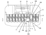
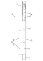
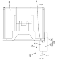
以下、本発明を具体化した実施例1を図1~図13を参照して説明する。尚、以下の説明において、前後方向については、図3,4,6,8における右方を前方と定義する。上下方向については、図2,4,6,8にあらわれる向きを、そのまま上方、下方と定義する。本実施例のコネクタは、3種類の端子付き電線10A,10B,10Cと、ハウジング30とを備えて構成されている。 <Example 1>
A first embodiment embodying the present invention will be described below with reference to FIGS. In the following description, for the front-rear direction, the right side in FIGS. As for the vertical direction, the directions appearing in FIGS. 2, 4, 6 and 8 are defined as “upper” and “lower” as they are. The connector of the present embodiment includes three types of electric wires with terminals 10 </ b> A, 10 </ b> B, and 10 </ b> C and ahousing 30.
以下、本発明を具体化した実施例1を図1~図13を参照して説明する。尚、以下の説明において、前後方向については、図3,4,6,8における右方を前方と定義する。上下方向については、図2,4,6,8にあらわれる向きを、そのまま上方、下方と定義する。本実施例のコネクタは、3種類の端子付き電線10A,10B,10Cと、ハウジング30とを備えて構成されている。 <Example 1>
A first embodiment embodying the present invention will be described below with reference to FIGS. In the following description, for the front-rear direction, the right side in FIGS. As for the vertical direction, the directions appearing in FIGS. 2, 4, 6 and 8 are defined as “upper” and “lower” as they are. The connector of the present embodiment includes three types of electric wires with terminals 10 </ b> A, 10 </ b> B, and 10 </ b> C and a
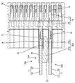
図4に示すように、3種類の端子付き電線10A,10B,10Cは、いずれも、被覆電線11と、端子金具15と、3種類のモールド部23A,23B,23Cとを一体化した形態であり、全体として前後方向に細長い導電路を構成する。被覆電線11は、3種類の端子付き電線10A,10B,10Cで共通の部材であり、アルミニウム製又はアルミニウム合金製の芯線12と、芯線12を包囲する略円筒状の絶縁被覆13とから構成されている。被覆電線11の前端部においては、絶縁被覆13が所定長さ分だけ剥き取られ、芯線12が露出している。この芯線12の露出領域14の前端部には、後述する端子金具15が圧着により接続されている。
As shown in FIG. 4, the three types of electric wires with terminals 10A, 10B, and 10C are all formed by integrating the covered electric wire 11, the terminal fitting 15, and the three types of mold portions 23A, 23B, and 23C. Yes, as a whole, an elongated conductive path is formed in the front-rear direction. The covered electric wire 11 is a member common to the three types of electric wires with terminals 10 </ b> A, 10 </ b> B, and 10 </ b> C, and includes an aluminum or aluminum alloy core wire 12 and a substantially cylindrical insulating coating 13 surrounding the core wire 12. ing. At the front end portion of the covered electric wire 11, the insulating coating 13 is peeled off by a predetermined length, and the core wire 12 is exposed. A terminal fitting 15 described later is connected to the front end portion of the exposed region 14 of the core wire 12 by crimping.
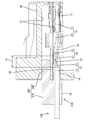
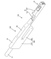
端子金具15も、被覆電線11と同様、3種類の端子付き電線10A,10B,10Cで共通の部品である。端子金具15は、所定形状に打ち抜いた銅製又は銅合金製の板材に曲げ加工等を施して成形したものであり、全体として前後方向に細長い形状をなしている。図4,11に示すように、端子金具15は、その前端側領域を構成する端子本体部16と、後端側領域を構成するバレル部19とから構成されている。端子本体部16は、角筒形をなす箱状接続部17と、箱状接続部17の後端に連なる連結部18とから構成されている。箱状接続部17には、端子金具15の前方から、雄形をなす相手側端子(図示省略)のタブが挿入されて接続されるようになっている。連結部18は、底壁部の左右両側縁から一対の側壁部を立ち上げた周知の形態である。
The terminal fitting 15 is also a component common to the three types of electric wires 10A, 10B, and 10C with the terminal, similarly to the covered electric wire 11. The terminal fitting 15 is formed by bending a copper or copper alloy plate material punched into a predetermined shape, and has an elongated shape in the front-rear direction as a whole. As shown in FIGS. 4 and 11, the terminal fitting 15 is composed of a terminal body portion 16 constituting the front end side region and a barrel portion 19 constituting the rear end side region. The terminal main body portion 16 includes a box-shaped connecting portion 17 having a rectangular tube shape and a connecting portion 18 connected to the rear end of the box-shaped connecting portion 17. A tab of a mating terminal (not shown) having a male shape is inserted into and connected to the box-shaped connecting portion 17 from the front of the terminal fitting 15. The connecting portion 18 is a well-known form in which a pair of side wall portions is raised from the left and right side edges of the bottom wall portion.
バレル部19は、連結部18の後端から後方へ細長く延びた基板部20と、基板部20の幅方向(左右方向)における両側縁から周方向(端子金具15長さ方向と交差する方向)に延出する対をなすカシメ片21とから構成された周知の形態の圧着手段である。バレル部19は、アプリケータと称される自動機(図示省略)により、被覆電線11(芯線12)の前端部に圧着される。圧着工程では、基板部20の後端部に載置された芯線12の前端部に対し、一対のカシメ片21が包囲するように曲げ変形させられる。
The barrel portion 19 is elongated in the backward direction from the rear end of the connecting portion 18 and the circumferential direction (direction intersecting the length direction of the terminal fitting 15) from both side edges in the width direction (left-right direction) of the substrate portion 20. This is a known form of crimping means composed of a pair of caulking pieces 21 extending in a straight line. The barrel portion 19 is crimped to the front end portion of the covered electric wire 11 (core wire 12) by an automatic machine (not shown) called an applicator. In the crimping step, the front end portion of the core wire 12 placed on the rear end portion of the substrate portion 20 is bent and deformed so as to surround the pair of crimping pieces 21.
カシメ片21の曲げ変形により、バレル部19には基板部20と一対のカシメ片21とで囲まれた圧着空間22が構成されている。この圧着空間22に収容された芯線12の前端部と、端子金具15とが導通可能に固着される。圧着状態では、被覆電線11の前端部と端子金具15がほぼ一直線状に連なった形態となる。バレル部19の圧着空間22のうち芯線12が収容されるのは後端部だけであり、圧着空間22のうち芯線12よりも前方の領域には、後述するモールド部23A,23B,23Cの一部が充填される。
Due to the bending deformation of the crimping piece 21, a pressure-bonding space 22 surrounded by the substrate part 20 and the pair of crimping pieces 21 is formed in the barrel part 19. The front end portion of the core wire 12 accommodated in the crimping space 22 and the terminal fitting 15 are fixed so as to be conductive. In the crimped state, the front end portion of the covered electric wire 11 and the terminal fitting 15 are connected in a substantially straight line. Of the crimping space 22 of the barrel portion 19, the core wire 12 is accommodated only in the rear end portion. In the crimping space 22 in a region in front of the core wire 12, one of mold parts 23 </ b> A, 23 </ b> B, 23 </ b> C, which will be described later. Part is filled.
第1~第3の3種類のモールド部23A,23B,23Cは、いずれも、芯線12に端子金具15を圧着した後に金型(図示省略)により成形される。モールド部23A,23B,23Cの成形は、周知の金型(図示省略)内にバレル部19の全体と、連結部18の後端部と、被覆電線11における絶縁被覆13の前端部とを収容し、金型の内部に溶融樹脂(図示省略)を注入し、注入した溶融樹脂を固化(硬化)させることによって行われる。成形工程では、溶融樹脂の一部がバレル部19の圧着空間22内に流入する。
The first to third types of mold parts 23A, 23B, and 23C are all formed by a mold (not shown) after the terminal fitting 15 is pressure-bonded to the core wire 12. Molding of the mold parts 23A, 23B, and 23C accommodates the entire barrel part 19, the rear end part of the connecting part 18, and the front end part of the insulating coating 13 in the covered electric wire 11 in a known mold (not shown). The molten resin (not shown) is injected into the mold, and the injected molten resin is solidified (cured). In the molding process, a part of the molten resin flows into the crimping space 22 of the barrel portion 19.
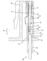
図3,11に示すように、成形後のモールド部23A,23B,23Cは、バレル部19の全体と、芯線12のうちバレル部19との圧着部を含む露出領域14の全体と、被覆電線11のうち絶縁被覆13が残存する領域の前端部とを全周に亘り液密状に包囲している。また、モールド部23A,23B,23Cの前端部の一部は、バレル部19よりも前方において連結部18の内部に収容されている。モールド部23A,23B,23Cのうちバレル部19を覆う領域の下面(外面)は、端子本体部16の下面(外面)とほぼ同じ高さである。端子付き電線10A,10B,10Cは、ハウジング30の後方から端子収容室31内に挿入され、挿入状態では、端子金具15の全体と、芯線12の露出領域14の全体と、絶縁被覆13の前端部とが端子収容室31内に収容されている。
As shown in FIGS. 3 and 11, the molded mold parts 23 </ b> A, 23 </ b> B, and 23 </ b> C include the entire barrel part 19, the entire exposed region 14 including the crimped part of the core wire 12 with the barrel part 19, and the covered electric wire. 11, the front end portion of the region where the insulating coating 13 remains is surrounded in a liquid-tight manner over the entire circumference. Further, part of the front end portions of the mold portions 23 </ b> A, 23 </ b> B, and 23 </ b> C are accommodated inside the connecting portion 18 in front of the barrel portion 19. The lower surface (outer surface) of the region covering the barrel portion 19 in the mold portions 23A, 23B, and 23C is substantially the same height as the lower surface (outer surface) of the terminal body portion 16. The terminal-attached electric wires 10A, 10B, and 10C are inserted into the terminal accommodating chamber 31 from the rear of the housing 30, and in the inserted state, the entire terminal fitting 15, the entire exposed region 14 of the core wire 12, and the front end of the insulating coating 13 are inserted. Are accommodated in the terminal accommodating chamber 31.
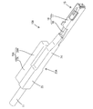
図5~8,12,13に示すように、モールド部23A,23B,23Cは、収容部24と、突出部25と、第1~第3当接部26A,26B,26Cのいずれかとを備えて構成されている。収容部24は、端子金具15の全体と芯線12の露出領域14の全体と絶縁被覆13の前端部とを液密状に包囲しており、端子付き電線10A,10B,10Cをハウジング30に取り付けた状態で端子収容室31内に収容される。突出部25は、収容部24の後端に連なって絶縁被覆13を液密状に包囲しており、端子付き電線10A,10B,10Cをハウジング30に取り付けた状態では、端子収容室31(ハウジング30)の後方外部に露出している。
As shown in FIGS. 5 to 8, 12, and 13, the mold portions 23A, 23B, and 23C include the accommodating portion 24, the protruding portion 25, and any one of the first to third contact portions 26A, 26B, and 26C. Configured. The accommodating portion 24 surrounds the entire terminal fitting 15, the entire exposed region 14 of the core wire 12, and the front end portion of the insulating coating 13 in a liquid-tight manner, and attaches the terminal-attached electric wires 10 </ b> A, 10 </ b> B, 10 </ b> C to the housing 30. In this state, the terminal is accommodated in the terminal accommodating chamber 31. The projecting portion 25 is connected to the rear end of the accommodating portion 24 and surrounds the insulating coating 13 in a liquid-tight manner. When the electric wires with terminals 10A, 10B, and 10C are attached to the housing 30, the protruding portion 25 is connected to the terminal accommodating chamber 31 (housing 30) and exposed to the rear outside.
収容部24と突出部25は、第1~第3の3種類の端子付き電線10A,10B,10C(第1~第3の3種類のモールド部23A,23B,23C)において共通の形状である。一方、第1~第3モールド部23A,23B,23Cのうち突出部25に形成された第1~第3当接部26A,26B,26Cは、3種類の端子付き電線10A,10B,10C間で互いに異なる形状である。
The accommodating portion 24 and the protruding portion 25 have a common shape in the first to third types of electric wires with terminals 10A, 10B, and 10C (first to third types of molded portions 23A, 23B, and 23C). . On the other hand, of the first to third mold parts 23A, 23B, 23C, the first to third contact parts 26A, 26B, 26C formed on the protruding part 25 are between the three types of terminal-attached electric wires 10A, 10B, 10C. The shapes are different from each other.
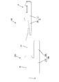
図5,6に示すように、第1端子付き電線10Aを構成する第1モールド部23A(請求項に記載のモールド部)の第1当接部26A(請求項に記載の当接部)は、第1張出部27Aと第1嵌入部28Aとから構成されている。第1張出部27Aは、突出部25の左側面から左側方へリブ状(又は、壁状)に張り出した形態である。前後方向における第1張出部27Aの形成領域は、突出部25の前端から後端に至る全長に亘って連続した範囲である。第1嵌入部28Aは、第1張出部27Aの前端から前方へ片持ち状に突出した形態である。図3に示すように、第1嵌入部28Aの右側面と収容部24の左側面との間には、左右に隣り合う端子収容室31間の隔壁32の厚さに相当するクリアランスが空いている。第1嵌入部28Aは、端子収容室31内へ上下方向及び左右方向へのガタ付きを生じることなく嵌入し得る形状に成形されている。
As shown in FIGS. 5 and 6, the first contact portion 26 </ b> A (the contact portion described in the claims) of the first mold portion 23 </ b> A (the mold portion described in the claims) constituting the first terminal-equipped electric wire 10 </ b> A is The first projecting portion 27A and the first insertion portion 28A are configured. 27 A of 1st overhang | projection parts are the forms protruded in the rib shape (or wall shape) from the left side surface of the protrusion part 25 to the left side. The region where the first projecting portion 27A is formed in the front-rear direction is a continuous range over the entire length from the front end to the rear end of the protrusion 25. 28 A of 1st insertion parts are the forms protruded to the front from the front end of 27 A of 1st overhang | projections in the shape of a cantilever. As shown in FIG. 3, a clearance corresponding to the thickness of the partition wall 32 between the terminal housing chambers 31 adjacent to each other is left between the right side surface of the first insertion portion 28 </ b> A and the left side surface of the housing portion 24. Yes. 28 A of 1st insertion parts are shape | molded in the shape which can be inserted in the terminal storage chamber 31, without producing the backlash in the up-down direction and the left-right direction.
図7,8に示すように、第2端子付き電線10Bを構成する第2モールド部23B(請求項に記載のモールド部)の第2当接部26B(請求項に記載の当接部)は、第2張出部27Bと第2嵌入部28Bとから構成されている。第2張出部27Bは、突出部25の下面から下方へリブ状(又は、壁状)に張り出した形態である。前後方向における第2張出部27Bの形成領域は、突出部25の前端から後端に至る全長に亘って連続した範囲である。第2嵌入部28Bは、第2張出部27Bの前端から前方へ片持ち状に突出した形態である。第2嵌入部28Bと収容部24の下面との間には、上下に隣り合う端子収容室31間の仕切壁33の厚さに相当するクリアランスが空いている。第2嵌入部28Bは、第1嵌入部28Aと同様、端子収容室31内へ上下方向及び左右方向へのガタ付きを生じることなく嵌入し得る形状に成形されている。
As shown in FIGS. 7 and 8, the second contact portion 26B (the contact portion according to the claims) of the second mold portion 23B (the mold portion according to the claims) constituting the electric wire 10B with the second terminal is as follows. The second projecting portion 27B and the second fitting portion 28B are configured. The 2nd overhang | projection part 27B is the form protruded below from the lower surface of the protrusion part 25 in rib shape (or wall shape). The formation region of the second projecting portion 27B in the front-rear direction is a continuous range over the entire length from the front end to the rear end of the protruding portion 25. The 2nd insertion part 28B is the form which protruded to the front from the front end of the 2nd overhang | projection part 27B in the shape of a cantilever. A clearance corresponding to the thickness of the partition wall 33 between the upper and lower terminal accommodating chambers 31 is vacant between the second insertion portion 28 </ b> B and the lower surface of the accommodating portion 24. Similarly to the first insertion portion 28A, the second insertion portion 28B is formed into a shape that can be inserted into the terminal accommodating chamber 31 without causing backlash in the vertical and horizontal directions.
図12,13に示すように、第3端子付き電線10Cを構成する第3モールド部23C(請求項に記載のモールド部)の第3当接部26C(請求項に記載の当接部)は、第3張出部27Cと外嵌部28Cとから構成されている。第3張出部27Cは、突出部25の左側面から左側方へリブ状(又は、壁状)に張り出した形態である。前後方向における第3張出部27Cの形成領域は、突出部25の前端から後端に至る全長に亘って連続した範囲である。外嵌部28Cは、第3張出部27Cの前端から前方へ片持ち状に突出した形態である。外嵌部28Cの右側面と収容部24の左側面との間には、左右方向における最端に位置する端子収容室31とハウジング30の外側面とを区画する外壁部34の厚さに相当するクリアランスが空いている。
As shown in FIGS. 12 and 13, the third contact portion 26 </ b> C (the contact portion described in the claims) of the third mold portion 23 </ b> C (the mold portion described in the claims) constituting the electric wire 10 </ b> C with the third terminal is The third projecting portion 27C and the outer fitting portion 28C are configured. The third projecting portion 27C has a form projecting in a rib shape (or wall shape) from the left side surface of the projecting portion 25 to the left side. The formation region of the third projecting portion 27C in the front-rear direction is a continuous range over the entire length from the front end to the rear end of the protruding portion 25. The outer fitting portion 28C has a form that protrudes forward in a cantilevered manner from the front end of the third overhang portion 27C. Between the right side surface of the outer fitting portion 28 </ b> C and the left side surface of the housing portion 24, the thickness corresponds to the thickness of the outer wall portion 34 that partitions the terminal housing chamber 31 positioned at the extreme end in the left-right direction and the outer surface of the housing 30. Clearance is available.
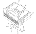
上述のように本実施例1のコネクタは、複数の端子収容室31が上下方向及び左右方向に並列して形成されたハウジング30と、各端子収容室31に個別に挿入される3種類(複数種類)の端子付き電線10A,10B,10Cとを備えている。端子付き電線10A,10B,10Cは、被覆電線11と端子金具15とモールド部23A,23B,23Cとを備えている。端子付き電線10A,10B,10Cは上下反転した姿勢でハウジング30に取り付けられる。端子付き電線10A,10B,10Cをハウジング30に取り付けた状態では、端子金具15の全体とモールド部23A,23B,23Cの前端側領域(収容部24)が端子収容室31内に収容される。
As described above, the connector according to the first embodiment includes a housing 30 in which a plurality of terminal accommodating chambers 31 are formed in parallel in the vertical direction and the left-right direction, and three types (plural types) that are individually inserted into each terminal accommodating chamber 31. Type) terminal-attached electric wires 10A, 10B, and 10C. The terminal-attached electric wires 10A, 10B, and 10C include the covered electric wire 11, the terminal fitting 15, and the mold parts 23A, 23B, and 23C. The terminal-attached electric wires 10A, 10B, and 10C are attached to the housing 30 in an upside down posture. In a state where the terminal-attached electric wires 10A, 10B, and 10C are attached to the housing 30, the entire terminal fitting 15 and the front end side regions (accommodating portions 24) of the molded portions 23A, 23B, and 23C are accommodated in the terminal accommodating chamber 31.
被覆電線11は、芯線12と、芯線12を包囲する絶縁被覆13とを有していて、被覆電線11の前端部では芯線12が露出されている。端子金具15の後端部には、絶縁被覆13と非接触の状態で芯線12の露出領域14(つまり、被覆電線11の前端部)に対し包囲するように圧着されたバレル部19が形成されている。
The covered electric wire 11 has a core wire 12 and an insulating coating 13 surrounding the core wire 12, and the core wire 12 is exposed at the front end portion of the covered electric wire 11. A barrel portion 19 is formed at the rear end portion of the terminal fitting 15 so as to surround the exposed region 14 of the core wire 12 (that is, the front end portion of the covered electric wire 11) without being in contact with the insulating coating 13. ing.
モールド部23A,23B,23Cは、端子金具15の全体と、被覆電線11のうちバレル部19との圧着部を含む前端部とを液密状に覆っている。即ち、モールド部23A,23B,23Cは、芯線12のうちバレル部19との圧着部を含む露出領域14の全体と、絶縁被覆13の前端部とを液密状に覆っている。芯線12はアルミニウム又はアルミニウム合金製であるのに対し、端子金具15は銅又は銅合金製であることから、芯線12と端子金具15(バレル部19)との接触部分における防食手段として、芯線12と端子金具15(バレル部19)との接触部分を合成樹脂製のモールド部23A,23B,23Cで液密状に包囲している。
The mold parts 23A, 23B, and 23C cover the entire terminal fitting 15 and the front end part including the crimp part with the barrel part 19 of the covered electric wire 11 in a liquid-tight manner. That is, the mold parts 23A, 23B, and 23C cover the entire exposed region 14 including the crimped part with the barrel part 19 in the core wire 12 and the front end part of the insulating coating 13 in a liquid-tight manner. The core wire 12 is made of aluminum or aluminum alloy, whereas the terminal fitting 15 is made of copper or copper alloy. Therefore, the core wire 12 is used as an anticorrosion means at the contact portion between the core wire 12 and the terminal fitting 15 (barrel portion 19). And the terminal fitting 15 (barrel portion 19) are surrounded in a liquid-tight manner by mold portions 23A, 23B, and 23C made of synthetic resin.
絶縁被覆13の外径は芯線12の外径より大きいため、モールド部23A,23B,23Cのうち絶縁被覆13を包囲する領域(突出部25)の外径は、モールド部23A,23B,23Cのうち芯線12を包囲する領域(収容部24)よりも大きくなる。この点に鑑みて、本実施例1の端子付き電線10A,10B,10Cを構成する端子金具15の後端部には、絶縁被覆13に対して包囲するように圧着されるインシュレーションバレル部を形成していない。したがって、端子収容室31の容積(高さ寸法や幅寸法)を拡大しなくても、モールド部23A,23B,23Cのうち端子金具15を包囲する領域全体を端子収容室31内に収容することができた。
Since the outer diameter of the insulating coating 13 is larger than the outer diameter of the core wire 12, the outer diameter of the region (projecting portion 25) surrounding the insulating coating 13 in the mold portions 23 A, 23 B, and 23 C is that of the mold portions 23 A, 23 B, and 23 C. It becomes larger than the area | region (accommodating part 24) which surrounds the core wire 12 among these. In view of this point, an insulation barrel portion that is crimped so as to surround the insulating coating 13 is provided at the rear end portion of the terminal fitting 15 that constitutes the electric wires with terminals 10A, 10B, and 10C of the first embodiment. Not formed. Therefore, the entire region surrounding the terminal fitting 15 in the mold portions 23A, 23B, and 23C is accommodated in the terminal accommodating chamber 31 without increasing the volume (height dimension or width dimension) of the terminal accommodating chamber 31. I was able to.
本実施例の端子金具15に形成されていないインシュレーションバレル部は、ハウジング30の外部における被覆電線11の曲げの影響が端子金具15と芯線12との圧着部分に及ぶのを抑制する曲げ抑制機能を備えている。そのため、本実施例のモールド部23A,23B,23Cには、防水機能だけでなく、インシュレーションバレル部に替わって曲げ抑制機能も求められる。そこで、本実施例の端子付き電線10A,10B,10Cには、モールド部23A,23B,23Cのうちハウジング30外へ突出した突出部25の変形を抑制するための手段として、突出部25には、当接部26A,26B,26Cが設けられている。
The insulation barrel portion that is not formed on the terminal fitting 15 of this embodiment has a bending suppression function that suppresses the influence of the bending of the covered electric wire 11 outside the housing 30 on the crimping portion between the terminal fitting 15 and the core wire 12. It has. Therefore, the mold parts 23A, 23B, and 23C of the present embodiment are required to have not only a waterproof function but also a bending suppression function in place of the insulation barrel part. Therefore, in the electric wires with terminals 10A, 10B, and 10C of the present embodiment, the protruding portions 25 are provided as means for suppressing deformation of the protruding portions 25 that protrude out of the housing 30 among the mold portions 23A, 23B, and 23C. The contact portions 26A, 26B, and 26C are provided.
具体的には、図1,2に示すように、第1端子付き電線10Aの端子金具15は、いずれの端子付き電線10A,10B,10Cも挿入されない空き端子収容室31の左隣に位置する端子収容室31に挿入される。第1端子付き電線10Aを端子収容室31に挿入すると、第1嵌入部28Aが、右隣の空き端子収容室31内に上下左右へのガタ付きを規制された状態で嵌入する。この第1嵌入部28Aの嵌入により、被覆電線11が上下左右へ曲げられても、第1嵌入部28Aに連なる突出部25の変形が抑制される。
Specifically, as shown in FIGS. 1 and 2, the terminal fitting 15 of the first terminal-attached electric wire 10 </ b> A is located on the left side of the empty terminal accommodating chamber 31 into which any of the electric wires 10 </ b> A, 10 </ b> B, 10 </ b> C with terminals is not inserted. It is inserted into the terminal accommodating chamber 31. When the first terminal-attached electric wire 10A is inserted into the terminal accommodating chamber 31, the first insertion portion 28A is inserted into the empty terminal accommodating chamber 31 on the right side in a state in which back and forth rattling is restricted. Even if the covered electric wire 11 is bent vertically and horizontally by the insertion of the first insertion portion 28A, the deformation of the protruding portion 25 connected to the first insertion portion 28A is suppressed.
また、第2端子付き電線10Bの端子金具15は、図1,2に示すように、いずれの端子付き電線10A,10B,10Cも挿入されない空き端子収容室31の下隣に位置する端子収容室31に挿入される。第2端子付き電線10Bを端子収容室31に挿入すると、第2嵌入部28Bが、上隣の空き端子収容室31内に上下左右へのガタ付きを規制された状態で嵌入する。この第2嵌入部28Bの嵌入により、被覆電線11が上下左右へ曲げられても、第2嵌入部28Bに連なる突出部25の変形が抑制される。
Further, as shown in FIGS. 1 and 2, the terminal fitting 15 of the second terminal-attached electric wire 10B is a terminal accommodating chamber located next to the empty terminal accommodating chamber 31 into which any of the electric wires 10A, 10B, 10C with terminals is not inserted. 31 is inserted. When the electric wire 10B with the second terminal is inserted into the terminal accommodating chamber 31, the second fitting portion 28B is fitted into the empty terminal accommodating chamber 31 adjacent to the upper terminal in a state in which the vertical and horizontal play is restricted. Even if the covered electric wire 11 is bent up and down and left and right by the insertion of the second insertion portion 28B, the deformation of the protruding portion 25 connected to the second insertion portion 28B is suppressed.
また、第3端子付き電線10Cの端子金具15は、図9に示すように、左右方向において最も端に位置する端子収容室31に挿入される。第3端子付き電線10Cを端子収容室31に挿入すると、外嵌部28Cがハウジング30の外壁部34の外面に面当たり状態で当接する。つまり、外嵌部28Cと、この外嵌部28Cに連なる突出部25とが、ハウジング30の外壁部34を左右方向に挟み付ける。この挟み付けにより、被覆電線11が左右へ曲げられても、第2嵌入部28Bに連なる突出部25の変形が抑制される。
Further, as shown in FIG. 9, the terminal fitting 15 of the third terminal-attached electric wire 10C is inserted into the terminal accommodating chamber 31 located at the end in the left-right direction. When the electric wire 10 </ b> C with the third terminal is inserted into the terminal accommodating chamber 31, the outer fitting portion 28 </ b> C comes into contact with the outer surface of the outer wall portion 34 of the housing 30 in a surface contact state. That is, the outer fitting portion 28 </ b> C and the protruding portion 25 connected to the outer fitting portion 28 </ b> C sandwich the outer wall portion 34 of the housing 30 in the left-right direction. Even if the covered electric wire 11 is bent to the left and right by this clamping, deformation of the protruding portion 25 connected to the second insertion portion 28B is suppressed.
上述のように、本実施例のコネクタは、モールド部23A,23B,23Cに形成した第1~第3のいずれかの当接部26A,26B,26Cを、ハウジング30に当接させることにより、モールド部23A,23B,23Cのうちハウジング30外へ突出した突出部25の変形を抑制することができる。このようにモールド部23A,23B,23Cの当接部26A,26B,26Cをハウジング30に当接させることにより、モールド部23A,23B,23Cの突出部25が変形し難くなるので、バレル部19における芯線12と端子金具15との接触状態が安定する。
As described above, the connector according to the present embodiment allows any one of the first to third contact portions 26A, 26B, and 26C formed on the mold portions 23A, 23B, and 23C to contact the housing 30. Of the mold parts 23A, 23B, and 23C, the deformation of the protruding part 25 protruding outside the housing 30 can be suppressed. Since the projecting portions 25 of the mold portions 23A, 23B, and 23C are not easily deformed by bringing the contact portions 26A, 26B, and 26C of the mold portions 23A, 23B, and 23C into contact with the housing 30 in this manner, the barrel portion 19 The contact state between the core wire 12 and the terminal fitting 15 is stabilized.
また、第1当接部26Aを構成する第1嵌入部28Aと、第2当接部26Bを構成する第2嵌入部28Bは、端子金具15が収容されていない空き端子収容室31の内壁に当接するので、ハウジング30(端子収容室31)の形状を変更しなくても、第1及び第2モールド部23A,23B(突出部25)の曲げ剛性を高めることができる。また、第3当接部26Cを構成する外嵌部28Cは、ハウジング30の外面に当接するので、ハウジング30の外面形状を変更したり、複雑化したりしなくても、第3モールド部23C(突出部25)の曲げ剛性を高めることができる。
The first insertion portion 28A constituting the first contact portion 26A and the second insertion portion 28B constituting the second contact portion 26B are formed on the inner wall of the empty terminal accommodation chamber 31 in which the terminal fitting 15 is not accommodated. Since it contacts, even if it does not change the shape of the housing 30 (terminal accommodating chamber 31), the bending rigidity of 1st and 2nd mold part 23A, 23B (projection part 25) can be improved. Further, the outer fitting portion 28C constituting the third contact portion 26C contacts the outer surface of the housing 30, so that the third mold portion 23C ( The bending rigidity of the protrusion 25) can be increased.
<他の実施例>
本発明は上記記述及び図面によって説明した実施例に限定されるものではなく、例えば次のような実施例も本発明の技術的範囲に含まれる。
(1)上記実施例1,2では、被覆電線の芯線をアルミニウム製又はアルミニウム合金製としたが、芯線の材料は、アルミニウムやアルミニウム合金に限らず、銅や銅合金等の他の金属であってもよい。
(2)上記実施例1,2では、端子金具を銅製又は銅合金製としたが、端子金具の材料は、銅や銅合金に限らず、アルミニウムやアルミニウム合金等の他の金属であってもよい。
(3)上記実施例1,2では、端子金具には、絶縁被覆に圧着されるインシュレーションバレル部は形成されていないが、本発明は、端子金具にインシュレーションバレル部が形成されている場合にも適用できる。
(4)上記実施例1,2では、端子収容室内には、被覆電線のうち絶縁被覆の前端部が収容されているが、被覆電線のうち絶縁被覆の前端部が端子収容室に収容されない形態としてもよい。この構成によれば、端子収容室の容積を拡大しなくても、モールド部を端子収容室内に収容することが可能である。 <Other embodiments>
The present invention is not limited to the embodiments described with reference to the above description and drawings. For example, the following embodiments are also included in the technical scope of the present invention.
(1) In Examples 1 and 2 above, the core wire of the covered electric wire is made of aluminum or aluminum alloy, but the material of the core wire is not limited to aluminum or aluminum alloy, but may be other metal such as copper or copper alloy. May be.
(2) In Examples 1 and 2, the terminal fitting is made of copper or copper alloy, but the material of the terminal fitting is not limited to copper or copper alloy, but may be other metals such as aluminum or aluminum alloy. Good.
(3) In the first and second embodiments, the terminal metal fitting is not formed with the insulation barrel portion that is crimped to the insulation coating, but the present invention is a case where the insulation metal barrel portion is formed on the terminal metal fitting. It can also be applied to.
(4) In the said Example 1, 2, although the front-end part of insulation coating is accommodated in a terminal storage chamber, the front end part of insulation coating is not accommodated in a terminal storage chamber among covered wires. It is good. According to this configuration, the mold part can be accommodated in the terminal accommodating chamber without increasing the volume of the terminal accommodating chamber.
11…被覆電線
12…芯線
13…絶縁被覆
14…芯線の露出領域
15…端子金具
19…バレル部
23A…第1モールド部(モールド部)
23B…第2モールド部(モールド部)
23C…第3モールド部(モールド部)
25…モールド部の突出部
26A…第1当接部(当接部)
26B…第2当接部(当接部)
26C…第3当接部(当接部)
30…ハウジング
31…端子収容室 DESCRIPTION OFSYMBOLS 11 ... Covered electric wire 12 ... Core wire 13 ... Insulation coating 14 ... Exposed area | region of core wire 15 ... Terminal metal fitting 19 ... Barrel part 23A ... 1st mold part (mold part)
23B ... 2nd mold part (mold part)
23C ... Third mold part (mold part)
25 ... Projection part ofmold part 26A ... First contact part (contact part)
26B: second contact portion (contact portion)
26C: Third contact portion (contact portion)
30 ...Housing 31 ... Terminal receiving chamber
12…芯線
13…絶縁被覆
14…芯線の露出領域
15…端子金具
19…バレル部
23A…第1モールド部(モールド部)
23B…第2モールド部(モールド部)
23C…第3モールド部(モールド部)
25…モールド部の突出部
26A…第1当接部(当接部)
26B…第2当接部(当接部)
26C…第3当接部(当接部)
30…ハウジング
31…端子収容室 DESCRIPTION OF
23B ... 2nd mold part (mold part)
23C ... Third mold part (mold part)
25 ... Projection part of
26B: second contact portion (contact portion)
26C: Third contact portion (contact portion)
30 ...
Claims (3)
- 芯線と、前記芯線を包囲する絶縁被覆とを有していて、前端部では前記芯線が露出されている被覆電線と、
端子金具と、
前記端子金具の後端部に形成され、前記被覆電線の前端部に対し包囲するように圧着されたバレル部と、
前記被覆電線のうち前記バレル部との圧着部を含む前端部を液密状に覆うモールド部と、
前記端子金具の全体と、前記モールド部の前端側領域とを収容する端子収容室が形成されたハウジングと、
前記モールド部に形成され、前記ハウジングに当接することで前記モールド部のうち前記ハウジング外へ突出した突出部の変形を抑制する当接部とを備えていることを特徴とするコネクタ。 A coated electric wire having a core wire and an insulating coating surrounding the core wire, wherein the core wire is exposed at the front end; and
Terminal fittings,
A barrel portion formed at the rear end portion of the terminal metal fitting and crimped so as to surround the front end portion of the covered electric wire;
A mold part that covers the front end part including the crimping part with the barrel part among the covered electric wires in a liquid-tight manner, and
A housing in which a terminal accommodating chamber for accommodating the entire terminal fitting and a front end side region of the mold part is formed;
A connector comprising: an abutting portion that is formed on the mold portion and abuts against the housing to suppress deformation of a protruding portion that protrudes out of the housing out of the mold portion. - 前記ハウジングには、複数の前記端子収容室が並列して形成されており、
前記当接部が、前記端子金具が収容されていない前記端子収容室の内壁に当接していることを特徴とする請求項1記載のコネクタ。 In the housing, a plurality of the terminal accommodating chambers are formed in parallel,
The connector according to claim 1, wherein the contact portion is in contact with an inner wall of the terminal accommodating chamber in which the terminal fitting is not accommodated. - 前記当接部が、前記ハウジングの外面に当接していることを特徴とする請求項1記載のコネクタ。 2. The connector according to claim 1, wherein the contact portion is in contact with an outer surface of the housing.
Priority Applications (2)
| Application Number | Priority Date | Filing Date | Title |
|---|---|---|---|
| US15/767,183 US10389044B2 (en) | 2015-10-12 | 2016-10-03 | Connector |
| CN201680058775.1A CN108140963B (en) | 2015-10-12 | 2016-10-03 | Connector with a locking member |
Applications Claiming Priority (2)
| Application Number | Priority Date | Filing Date | Title |
|---|---|---|---|
| JP2015-201649 | 2015-10-12 | ||
| JP2015201649A JP6468156B2 (en) | 2015-10-12 | 2015-10-12 | connector |
Publications (1)
| Publication Number | Publication Date |
|---|---|
| WO2017065044A1 true WO2017065044A1 (en) | 2017-04-20 |
Family
ID=58517253
Family Applications (1)
| Application Number | Title | Priority Date | Filing Date |
|---|---|---|---|
| PCT/JP2016/079365 WO2017065044A1 (en) | 2015-10-12 | 2016-10-03 | Connector |
Country Status (4)
| Country | Link |
|---|---|
| US (1) | US10389044B2 (en) |
| JP (1) | JP6468156B2 (en) |
| CN (1) | CN108140963B (en) |
| WO (1) | WO2017065044A1 (en) |
Families Citing this family (3)
| Publication number | Priority date | Publication date | Assignee | Title |
|---|---|---|---|---|
| USD876366S1 (en) * | 2018-02-23 | 2020-02-25 | J.S.T. Corporation | Electrical connector assembly |
| USD877703S1 (en) * | 2018-02-23 | 2020-03-10 | J.S.T. Corporation | Electrical connector assembly |
| USD906982S1 (en) * | 2019-02-28 | 2021-01-05 | Molex, Llc | Connector |
Citations (3)
| Publication number | Priority date | Publication date | Assignee | Title |
|---|---|---|---|---|
| JPS6484580A (en) * | 1987-09-28 | 1989-03-29 | Ngk Spark Plug Co | Water-proof connector |
| JP2012084407A (en) * | 2010-10-12 | 2012-04-26 | Yazaki Corp | Wire connection structure for connector terminal |
| JP2013045576A (en) * | 2011-08-23 | 2013-03-04 | Yazaki Corp | Connector terminal |
Family Cites Families (7)
| Publication number | Priority date | Publication date | Assignee | Title |
|---|---|---|---|---|
| JP2004055391A (en) * | 2002-07-22 | 2004-02-19 | Auto Network Gijutsu Kenkyusho:Kk | Connector for flat wiring material |
| JP4924889B2 (en) * | 2007-05-09 | 2012-04-25 | 住友電装株式会社 | Connector cover |
| US7717733B1 (en) * | 2008-12-10 | 2010-05-18 | Hon Hai Precision Ind. Co., Ltd. | Cable assembly having enhanced interconnection device thereof |
| JP2011040264A (en) * | 2009-08-10 | 2011-02-24 | Sumitomo Wiring Syst Ltd | Wiring direction restricting tool |
| JP5777861B2 (en) | 2010-06-14 | 2015-09-09 | 古河電気工業株式会社 | Production method of wire harness and wire terminal anticorrosion structure |
| JP5741343B2 (en) * | 2011-09-20 | 2015-07-01 | 住友電装株式会社 | connector |
| CN203166107U (en) * | 2013-04-12 | 2013-08-28 | 莫列斯公司 | Cable connector |
-
2015
- 2015-10-12 JP JP2015201649A patent/JP6468156B2/en not_active Expired - Fee Related
-
2016
- 2016-10-03 WO PCT/JP2016/079365 patent/WO2017065044A1/en active Application Filing
- 2016-10-03 CN CN201680058775.1A patent/CN108140963B/en not_active Expired - Fee Related
- 2016-10-03 US US15/767,183 patent/US10389044B2/en not_active Expired - Fee Related
Patent Citations (3)
| Publication number | Priority date | Publication date | Assignee | Title |
|---|---|---|---|---|
| JPS6484580A (en) * | 1987-09-28 | 1989-03-29 | Ngk Spark Plug Co | Water-proof connector |
| JP2012084407A (en) * | 2010-10-12 | 2012-04-26 | Yazaki Corp | Wire connection structure for connector terminal |
| JP2013045576A (en) * | 2011-08-23 | 2013-03-04 | Yazaki Corp | Connector terminal |
Also Published As
| Publication number | Publication date |
|---|---|
| CN108140963A (en) | 2018-06-08 |
| JP6468156B2 (en) | 2019-02-13 |
| US20180301827A1 (en) | 2018-10-18 |
| US10389044B2 (en) | 2019-08-20 |
| JP2017076458A (en) | 2017-04-20 |
| CN108140963B (en) | 2019-12-20 |
Similar Documents
| Publication | Publication Date | Title |
|---|---|---|
| JP5777861B2 (en) | Production method of wire harness and wire terminal anticorrosion structure | |
| US8998659B2 (en) | Crimping terminal | |
| JP5098890B2 (en) | Connection structure between wires and terminal fittings | |
| JP6154106B2 (en) | Resin mold method for wire terminal connection portion and mold for resin mold | |
| JP2014013657A (en) | Connector terminal and method of stopping water of the connector terminal | |
| US20130133946A1 (en) | Terminal fitting | |
| WO2017065044A1 (en) | Connector | |
| JPWO2010029803A1 (en) | Terminal fittings and electric wires with terminal fittings | |
| JP2013045576A (en) | Connector terminal | |
| US10608370B2 (en) | Wire with a core, a terminal with barrels crimped to the core and a molded portion covering the barrels and the core | |
| US10411366B2 (en) | Connector housing containing a wire terminal with a molded portion | |
| JP5387477B2 (en) | Terminal bracket with wire | |
| JP5720590B2 (en) | connector | |
| WO2017065041A1 (en) | Connector and wire with terminal | |
| JP6286385B2 (en) | connector | |
| US11152720B2 (en) | Terminal-equipped wire and wire harness | |
| JP6092669B2 (en) | connector | |
| JP2017191654A (en) | connector | |
| JP2013168306A (en) | Electric wire with connector | |
| JP2014053183A (en) | Electrical connection unit | |
| WO2017068953A1 (en) | Terminal-equipped electric wire and connector | |
| JP2013187105A (en) | Electric wire with connector |
Legal Events
| Date | Code | Title | Description |
|---|---|---|---|
| 121 | Ep: the epo has been informed by wipo that ep was designated in this application |
Ref document number: 16855298 Country of ref document: EP Kind code of ref document: A1 |
|
| WWE | Wipo information: entry into national phase |
Ref document number: 15767183 Country of ref document: US |
|
| NENP | Non-entry into the national phase |
Ref country code: DE |
|
| 122 | Ep: pct application non-entry in european phase |
Ref document number: 16855298 Country of ref document: EP Kind code of ref document: A1 |