WO2017061623A1 - Moving apparatus - Google Patents
Moving apparatus Download PDFInfo
- Publication number
- WO2017061623A1 WO2017061623A1 PCT/JP2016/080021 JP2016080021W WO2017061623A1 WO 2017061623 A1 WO2017061623 A1 WO 2017061623A1 JP 2016080021 W JP2016080021 W JP 2016080021W WO 2017061623 A1 WO2017061623 A1 WO 2017061623A1
- Authority
- WO
- WIPO (PCT)
- Prior art keywords
- wheel
- moving
- rotation
- moving device
- omnidirectional
- Prior art date
Links
Images


Classifications
-
- A—HUMAN NECESSITIES
- A61—MEDICAL OR VETERINARY SCIENCE; HYGIENE
- A61B—DIAGNOSIS; SURGERY; IDENTIFICATION
- A61B90/00—Instruments, implements or accessories specially adapted for surgery or diagnosis and not covered by any of the groups A61B1/00 - A61B50/00, e.g. for luxation treatment or for protecting wound edges
-
- A—HUMAN NECESSITIES
- A61—MEDICAL OR VETERINARY SCIENCE; HYGIENE
- A61G—TRANSPORT, PERSONAL CONVEYANCES, OR ACCOMMODATION SPECIALLY ADAPTED FOR PATIENTS OR DISABLED PERSONS; OPERATING TABLES OR CHAIRS; CHAIRS FOR DENTISTRY; FUNERAL DEVICES
- A61G13/00—Operating tables; Auxiliary appliances therefor
-
- B—PERFORMING OPERATIONS; TRANSPORTING
- B60—VEHICLES IN GENERAL
- B60B—VEHICLE WHEELS; CASTORS; AXLES FOR WHEELS OR CASTORS; INCREASING WHEEL ADHESION
- B60B19/00—Wheels not otherwise provided for or having characteristics specified in one of the subgroups of this group
-
- B—PERFORMING OPERATIONS; TRANSPORTING
- B60—VEHICLES IN GENERAL
- B60B—VEHICLE WHEELS; CASTORS; AXLES FOR WHEELS OR CASTORS; INCREASING WHEEL ADHESION
- B60B33/00—Castors in general; Anti-clogging castors
Definitions
- the present disclosure relates to a moving device having wheels.
- a moving device having a base on which an object is placed and four omnidirectional wheels attached to the back surface of the base is known (see Patent Document 1).
- the omnidirectional wheel is a well-known wheel having rotation axes in at least two directions different from each other.
- this indication is providing the technique which can move the moving apparatus which has a wheel to the direction which a user desires easily.
- One aspect of the present disclosure is a moving device including a base, a moving wheel, and a limiting mechanism.
- the base has a placement surface on which an object is placed.
- Each of the moving wheels is attached to a different position on the back side opposite to the mounting surface of the base.
- the limiting mechanism limits the rotational direction of the moving wheel so that the rotational direction of the moving wheel is concentric from a reference point that is a specified point.
- the moving direction of the moving wheel can be limited to an arc centered on the reference point.
- the direction of movement of the mobile device itself can be restricted, and the movement of the mobile device in a direction not intended by the user can be reduced.
- the moving device having the wheels can be easily moved in the direction desired by the user.
- One embodiment of the present disclosure is a moving device including a base, omnidirectional wheels, and a locking mechanism.
- the base has a placement surface on which an object is placed.
- the omnidirectional wheels are respectively attached to different positions on the back surface opposite to the mounting surface of the base.
- the omnidirectional wheel mentioned here has at least two or more rotating shafts that rotate in different directions.
- the locking mechanism is locked to the contact surface so as to be pivotally supported by the contact surface with which the omnidirectional wheel contacts.
- the direction in which the omnidirectional wheel can rotate can be limited to the direction of turning about the point pivotally supported by the locking mechanism.
- the moving direction of the moving device itself can be limited, and the moving device can be prevented from moving in a direction not intended by the user.
- the moving device having the wheels can be easily moved in the direction desired by the user.
- symbol in the parenthesis described in the claim shows the correspondence with the specific means as described in embodiment mentioned later as one aspect, Comprising: The technical scope of this indication is limited is not.
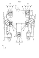
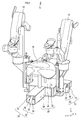
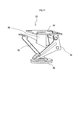
- a moving device 1 shown in FIG. 1 is a device that moves an object.
- the moving device 1 moves a medical action or a device used for assisting a medical action and an operator.
- the surgeon is a person who performs medical practice and assistance for medical practice, and includes, for example, a doctor, a dentist, a nurse, and a dental hygienist.
- the moving device 1 includes a chair 10, a medical device 12, a base 20, and a moving mechanism 30.
- the chair 10 includes a seat surface on which a person is seated.
- the medical device 12 is various devices necessary for medical practice or assistance for medical practice. As an example of the medical device 12, two articulated arms that support the implementation of surgery as a medical practice can be considered.
- the medical device 12 is not limited to a multi-joint arm, and may be, for example, a nerve function monitoring device, a biological monitoring device, a biological examination device, or the like.
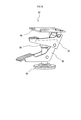
- the base 20 is a base having a placement surface 22 on which an object is placed.
- the base 20 in the present embodiment includes a main body portion 26 formed in a rectangular shape, and a long projecting portion 28 extending from the main body portion 26.
- the chair 10 and the medical device 12 are placed on the placement surface 22 of the base 20 as objects.
- the moving mechanism 30 is a mechanism that moves the moving device 1.
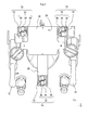
- the moving mechanism 30 of this embodiment includes a plurality of omnidirectional wheels 32, a plurality of unidirectional wheels 40, and a plurality of movable mechanisms 60. In the present embodiment, “three” omnidirectional wheels 32 and “two” unidirectional wheels 40 are provided.
- the movable mechanism 60 is provided for each one-way wheel 40.
- Each of the omnidirectional wheels 32 is a known wheel having at least two or more rotation shafts that rotate in different directions.
- the omnidirectional wheel 32 includes a main wheel 34 and a sub wheel 36.
- the main wheel 34 is a wheel having a first rotation shaft that rotates in one rotation direction.
- the auxiliary wheel 36 has a second rotating shaft that rotates in a direction different from the first rotating shaft of the main wheel 34, and is a wheel having a diameter smaller than the diameter of the main wheel 34.
- the auxiliary wheel 36 is pivotally supported on the side surface of the main wheel 34 so that the second rotation axis is orthogonal to the first rotation axis.
- the omnidirectional wheel 32 can rotate in the rotation direction of the main wheel 34 and the rotation direction of the auxiliary wheel 36, and can rotate in all directions by adjusting the rotation speed of the main wheel 34 and the rotation speed of the auxiliary wheel 36.
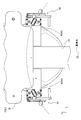
- the omnidirectional wheels 32 are attached to different positions on the back surface 24 of the base 20.
- the back surface 24 of the base 20 is a surface opposite to the placement surface 22.
- one omnidirectional wheel 32 is attached to each of the rear end portion of the main body portion 26 of the base 20 and the front end portion of the protruding portion 28 of the base 20. It has been.
- each one-way wheel 40 is a wheel having one rotation axis.
- Each of the one-way wheels 40 is attached to different positions on the back surface 24 of the base 20 as shown in FIG. Specifically, on the back surface 24 of the base 20, one unidirectional wheel 40 is attached to each of the front end portions of the main body portion 26 of the base 20.
- the one-way wheel 40 is an example of a moving wheel.
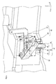
- each one-way wheel 40 is a so-called caster provided with a wheel 44 and a restriction mechanism 46, respectively.
- the wheel 44 is a wheel having one rotating shaft that rotates in one direction.
- the limiting mechanism 46 is a well-known mechanism that supports the rotating shaft of the wheel 44 so that the wheel 44 can rotate, and fixes the one-way wheel 40 to the mounted portion 52 that is a part of the base 20.
- plate-shaped holding portions 49 and 50 that extend in the same direction from a support portion formed in a rectangular plate shape and support the rotation shaft of the wheel 44, and a mounted portion of the base 20
- a well-known mechanism including a mounting shaft 54 for fixing the one-way wheel 40 to 52 can be considered.
- the limiting mechanism 46 is arranged so that the direction of the axis perpendicular to the rotation axis of the wheel 44 coincides with the tangent of the circle centered on the reference point on the xy plane.
- the rotation direction of the wheel 44 is fixed.
- the xy plane referred to here is a plane on which the wheel 44 of the one-way wheel 40 contacts and the moving device 1 moves.
- the reference point mentioned here is one point (that is, a coordinate) defined on the xy plane.
- match here means that the difference between the tangent of the circle and the direction of the axis orthogonal to the rotation axis of the wheel 44 is “0”, and that the difference can be regarded as “0” in advance. Includes cases that are within the specified tolerance.
- the limiting mechanism 46 fixes the one-way wheel 40 so that the rotation direction of the one-way wheel 40 is concentric with respect to the reference point.
- a method for fixing the rotation direction of the wheel 44 for example, a method in which the mounting shaft 54 is configured by screws, bolts / nuts, rivets, pins, etc., and fixed to the mounted portion 52 of the base 20 is conceivable.
- the method of fixing the rotation direction of the wheel 44 is not limited to this, and for example, the support portion of the caster is joined to the attached portion 52 of the base 20 using welding, brazing, pressure welding, or the like. Can be considered.
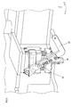
- the movable mechanism 60 is a well-known mechanism that moves each of the unidirectional wheels 40 in a direction perpendicular to the base 20. Specifically, as shown in FIGS. 4 and 5, the movable mechanism 60 includes a down lever 62 and an up lever 64, and moves the one-way wheel 40 between the contact position and the release position.
- the contact position is a position where the wheel 44 of the one-way wheel 40 contacts the xy plane.
- the release position is a position where the wheel 44 of the one-way wheel 40 is released from the contact position and is not in contact with the xy plane.
- the down lever 62 is a link mechanism that moves the one-way wheel 40 in the vertical direction so that the wheel 44 of the one-way wheel 40 is located at the contact position.
- the up lever 64 is a link mechanism that moves the one-way wheel 40 located at the contact position to the release position.
- the moving device 1 having wheels can be easily moved in the direction desired by the operator (that is, the user).
- the rotation direction of the one-way wheel 40 is fixed so that the axis orthogonal to the rotation axis of the one-way wheel 40 coincides with the tangent of a circle centered on the reference point. ing. Thereby, the moving direction of the moving apparatus 1 can be restricted reliably, and the movement of the moving apparatus 1 can be brought close to what the user intended.
- each of the one-way wheels 40 can be moved to the contact position and the release position by the movable mechanism 60. Thereby, according to the moving apparatus 1, when it is necessary to restrict
- the one-way wheel 40 may not be used.
- the limiting mechanism 46 in the above embodiment fixes the one-way wheel 40 to the mounted portion 52 of the base 20, but the limiting mechanism 46 further has a direction in the rotational direction of the wheel 44. May be configured to be changeable.
- the limiting mechanism 46 may be realized by rotating the mounting shaft 54 to change the direction of the rotation direction of the wheel 44 (that is, the direction of the axis orthogonal to the rotation axis of the wheel 44).
- the rotation of the mounting shaft 54 may be performed manually by the user, or may be realized by a driving force generated by electricity, air pressure, hydraulic pressure, or the like.
- the direction in which the moving device 1 moves can be adjusted, and the convenience for the surgeon can be improved.
- the number of unidirectional wheels 40 included in the moving device 1 is “2”, but the number of unidirectional wheels 40 included in the moving device 1 is “3”. It may be “4” or more.
- the moving device of the second embodiment is mainly different from the moving device 1 of the first embodiment in the moving mechanism. For this reason, in the present embodiment, the same components as those in the first embodiment are denoted by the same reference numerals, description thereof is omitted, and a description will be given focusing on a moving mechanism different from that in the first embodiment.
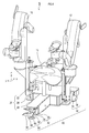
- the moving device 3 of the present embodiment includes a chair 10, a medical device 12, a base 20, and a moving mechanism 70.
- the moving mechanism 70 is a mechanism that moves the moving device 3.
- the moving mechanism 70 includes a plurality of omnidirectional wheels 32 and a limiting mechanism 72.
- Each of the omnidirectional wheels 32 is a known wheel having at least two or more rotating shafts that rotate in different directions, and includes a main wheel 34 and a sub wheel 36. As shown in FIG. 7, the omnidirectional wheels 32 in the present embodiment are attached to different positions on the back surface 24 of the base 20. Specifically, on the back surface 24 of the base 20, one omnidirectional wheel 32 is attached to each of the rear end portion of the main body portion 26 of the base 20 and the front end portion of the protruding portion 28 of the base 20. It has been.
- the omnidirectional wheel 32 in the present embodiment is an example of a moving wheel.
- the rear end is the upper side shown in FIG. 7, and the front end is the lower side shown in FIG.
- the limiting mechanism 72 is a mechanism that limits the rotation of the main wheel 34.
- the limiting mechanism 72 may be configured as a known brake that applies a braking force to the main wheel 34. With such a limiting mechanism 72, the omnidirectional wheel 32 can be rotated only by the auxiliary wheel 36 contacting the contact surface, and the moving direction of the omnidirectional wheel 32 can be limited to one direction.
- the limiting mechanism 72 rotates the omnidirectional wheel 32 in the rotational direction so that the direction of the axis orthogonal to the rotational axis of the auxiliary wheel 36 coincides with the tangent of the circle centered on the reference point on the xy plane.
- the xy plane referred to here is a plane on which the auxiliary wheel 36 of the omnidirectional wheel 32 contacts and the moving device 3 moves.
- the reference point mentioned here is one point (that is, a coordinate) defined on the xy plane.
- match here means that the difference between the tangent of the circle and the direction of the axis orthogonal to the rotation axis of the auxiliary wheel 36 is “0”, and the difference can be regarded as “0”. Including the case where it is within a predetermined allowable range.
- the restricting mechanism 72 fixes the omnidirectional wheel 32 so that the rotational direction of the omnidirectional wheel 32 is concentric with the reference point.
- the limiting mechanism 72 includes an angle adjustment mechanism.
- This angle adjustment mechanism sets the rotation direction of each of the auxiliary wheels 36 to be freely changeable.
- the angle adjustment mechanism in the present embodiment is a known mechanism that adjusts the attachment angle of each omnidirectional wheel 32 to the base 20.
- the adjustment of the attachment angle to the base 20 may be realized by rotating the attachment shaft of each omnidirectional wheel 32 to the base 20.
- the rotation of the mounting shaft may be performed manually by the user, or may be realized by a driving force generated by electricity, air pressure, hydraulic pressure, or the like.
- the moving direction of the moving apparatus 3 can be restrict
- the rotation of the first rotation shaft of the main wheel 34 is performed so that the axis orthogonal to the rotation axis of the auxiliary wheel 36 coincides with the tangent of the circle centered on the reference point. Restricted.
- the moving direction of the moving apparatus 3 can be restrict
- the limiting mechanism 72 can freely change the rotation direction of the auxiliary wheel 36 of the omnidirectional wheel 32. According to such a moving device 3, the moving direction of the moving device 3 can be freely adjusted, and the operator can use it easily.
- the moving device of the third embodiment is mainly different from the moving device 1 of the first embodiment in the moving mechanism. For this reason, in the present embodiment, the same components as those in the first embodiment are denoted by the same reference numerals, description thereof is omitted, and a description will be given focusing on a moving mechanism different from that in the first embodiment.
- the moving device 5 of this embodiment includes a chair 10, a medical device 12, a base 20, and a moving mechanism 80.
- the moving mechanism 80 is a mechanism that moves the moving device 5.
- the moving mechanism 80 includes a plurality of omnidirectional wheels 32 and one locking mechanism 82.
- the moving device 5 includes “three” omnidirectional wheels 32.
- Each of the omnidirectional wheels 32 is a known wheel having at least two or more rotating shafts that rotate in different directions.
- the omnidirectional wheel 32 includes a main wheel 34 and a sub wheel 36. That is, the omnidirectional wheel 32 can rotate in the rotation direction of the main wheel 34 and the rotation direction of the auxiliary wheel 36, and can rotate in all directions by adjusting the rotation speed of the main wheel 34 and the rotation speed of the auxiliary wheel 36. .
- the omnidirectional wheels 32 are respectively attached to different positions on the back surface 24 on the opposite side of the mounting surface 22 of the base 20. Specifically, on the back surface 24 of the base 20, one omnidirectional wheel 32 is attached to each of the rear end portion of the main body portion 26 of the base 20 and the front end portion of the protruding portion 28 of the base 20. It has been.
- the rear end is an upper end portion shown in FIG. 9, and the front end is a lower end shown in FIG. ⁇ Locking mechanism>
- the locking mechanism 82 pivotally supports the moving device 5 on a contact surface with which the omnidirectional wheel 32 comes into contact.
- the contact surface referred to here is a plane (for example, an xy plane) on which the wheel 44 of the one-way wheel 40 contacts and the moving device 5 moves.
- the locking mechanism 82 includes a connecting portion 84, a shaft portion 86, a locking portion 88, a down lever 90, and an up lever 92.
- the connecting portion 84 connects the locking mechanism 82 to the protruding portion 28 of the base 20.
- the shaft portion 86 is a shaft that connects the connecting portion 84 and the locking portion 88.
- the shaft portion 86 has, for example, a piston / cylinder.
- the locking portion 88 is pivotally connected to one end of the shaft portion 86.
- a member formed in a plate shape can be considered.
- the down lever 90 is a link mechanism that moves the locking portion 88 downward along the vertical direction. As the amount of movement from the initial position increases, the down lever 90 pushes the locking portion 88 downward along the vertical direction.
- the up lever 92 is a link mechanism that moves the locking portion 88 upward along the vertical direction. That is, when the down lever 90 is pushed downward in the locking mechanism 82, the locking portion 88 is pressed against the contact surface. Thereby, the frictional force between the contact surface and the locking portion 88 is increased, and the locking portion 88 is locked to the contact surface. And since the axial part 86 is rotatable with respect to the latching
- the down lever 90 pushes down the latching
- the moving direction of the moving device 5 can be limited to the turning direction around the point on the contact surface locked by the locking mechanism 82.
- the moving direction of the moving device 5 can be set only to the direction intended by the operator, and the movement of the moving device 5 in the direction not intended by the operator can be reduced. (3.2b) Further, according to the moving device 5, the engagement force with the contact surface can be adjusted by the amount by which the down lever 90 is pushed down.
- the locking mechanism 82 of the third embodiment presses the locking portion 88 formed in a plate shape against the contact surface, the locking portion 88 is locked to the contact surface.
- the structure of the locking mechanism 82 is not limited to this.
- the locking part 88 may be locked to the contact surface by forming the locking part 88 with a suction cup and attaching the suction cup to the contact surface.
- the edge (henceforth a latching end) on the opposite side to the end to which the axial part 86 was connected may be comprised as a pile. If comprised in this way, the axial part 86 can be latched to a contact surface by driving a latching end into a contact surface, and the moving apparatus 5 can turn centering on the latching part 88 as a turning center.
- this indication is not limited to the above-mentioned embodiment, and can be carried out in various modes in the range which does not deviate from the gist of this indication.
- the moving devices 1, 3, and 5 of the first embodiment, the second embodiment, and the third embodiment include the chair 10 and the medical device 12, respectively, the moving device includes the chair 10 and the medical device. At least one of the devices 12 may be omitted.
- the base 20 in the moving device may include only the main body portion 26. That is, the moving device may be configured as a carriage that carries an object. (4b)
- omitted a part of structure of the said embodiment is also embodiment of this indication.
- an aspect configured by appropriately combining the above embodiment and the modification is also an embodiment of the present disclosure.
- all the aspects included in the technical idea specified by the wording described in the claims are embodiments of the present disclosure.
Abstract
This moving apparatus (1, 3) is provided with a base platform (20), moving wheels (32, 40) and a restricting mechanism (46, 72). The base platform has a mounting surface on which an object is mounted. The moving wheels are attached to different positions on the back surface of the base platform, opposite of the mounting surface. The restricting mechanism restricts the rotation direction of the moving wheels such that the rotation direction of the moving wheels is concentric from a reference point, which is a defined point.
Description
本国際出願は、2015年10月7日に日本国特許庁に出願された日本国特許出願番号第2015-199656号に基づくものであって、その優先権の利益を主張するものであり、日本国特許出願番号第2015-199656号のすべての内容が参照により本明細書に組み入れられる。
This international application is based on Japanese Patent Application No. 2015-199656 filed with the Japan Patent Office on October 7, 2015 and claims the benefit of its priority. The entire contents of National Patent Application No. 2015-199656 are incorporated herein by reference.
本開示は、車輪を有した移動装置に関する。
The present disclosure relates to a moving device having wheels.
物体が載置される基台と、基台の裏面に取り付けられた4つの全方向車輪とを備えた移動装置が知られている(特許文献1参照)。全方向車輪は、互いに異なる少なくとも2方向以上の回転軸を有した周知の車輪である。
A moving device having a base on which an object is placed and four omnidirectional wheels attached to the back surface of the base is known (see Patent Document 1). The omnidirectional wheel is a well-known wheel having rotation axes in at least two directions different from each other.
特許文献1に記載された移動装置では、4つの全方向車輪のそれぞれが互いに独立して回転する。しかしながら、発明者の詳細な検討の結果、利用者が望む特定の方向へと、移動装置を移動させることが困難であるという課題が見出された。
In the moving device described in Patent Document 1, each of the four omnidirectional wheels rotate independently of each other. However, as a result of detailed studies by the inventor, it has been found that it is difficult to move the moving device in a specific direction desired by the user.
つまり、従来の技術では、車輪を有した移動装置を、利用者が望む方向へと容易に移動させることが困難であるという課題があった。
そこで、本開示は、車輪を有した移動装置を、利用者が望む方向へと容易に移動させることが可能な技術を提供することにある。 That is, in the conventional technology, there is a problem that it is difficult to easily move the moving device having the wheels in the direction desired by the user.
Then, this indication is providing the technique which can move the moving apparatus which has a wheel to the direction which a user desires easily.
本開示の一態様は、基台と、移動車輪と、制限機構とを備えた移動装置である。
基台は、物体が載置される載置面を有する。移動車輪は、基台の載置面とは反対側の裏面の異なる位置にそれぞれが取り付けられる。制限機構は、移動車輪の回転方向が、規定された一点である基準点から同心円状となるように、移動車輪の回転方向を制限する。 One aspect of the present disclosure is a moving device including a base, a moving wheel, and a limiting mechanism.
The base has a placement surface on which an object is placed. Each of the moving wheels is attached to a different position on the back side opposite to the mounting surface of the base. The limiting mechanism limits the rotational direction of the moving wheel so that the rotational direction of the moving wheel is concentric from a reference point that is a specified point.
このような移動装置によれば、移動車輪の移動の方向を、基準点を中心とした円弧上に制限できる。これにより、移動装置自体の移動の方向を制限でき、利用者が意図しない方向に移動装置が移動することを低減できる。
According to such a moving device, the moving direction of the moving wheel can be limited to an arc centered on the reference point. Thereby, the direction of movement of the mobile device itself can be restricted, and the movement of the mobile device in a direction not intended by the user can be reduced.
換言すると、車輪を有した移動装置を、利用者が望む方向へと容易に移動させることが可能となる。
また、本開示の一態様は、基台と、全方向車輪と、係止機構とを備えた移動装置である。 In other words, the moving device having the wheels can be easily moved in the direction desired by the user.
One embodiment of the present disclosure is a moving device including a base, omnidirectional wheels, and a locking mechanism.
また、本開示の一態様は、基台と、全方向車輪と、係止機構とを備えた移動装置である。 In other words, the moving device having the wheels can be easily moved in the direction desired by the user.
One embodiment of the present disclosure is a moving device including a base, omnidirectional wheels, and a locking mechanism.
基台は、物体が載置される載置面を有する。全方向車輪は、基台の載置面とは反対側の裏面の異なる位置にそれぞれが取り付けられる。ここで言う全方向車輪とは、互いに異なる方向に回転する少なくとも2以上の回転軸を有している。
The base has a placement surface on which an object is placed. The omnidirectional wheels are respectively attached to different positions on the back surface opposite to the mounting surface of the base. The omnidirectional wheel mentioned here has at least two or more rotating shafts that rotate in different directions.
係止機構は、全方向車輪が接触する接触面に軸支されるように、接触面に係止する。
このような移動装置によれば、全方向車輪が回転可能となる方向を、係止機構によって軸支されたポイントを中心として旋回する方向に制限できる。これにより、移動装置自体の移動の方向を制限でき、利用者が意図しない方向に移動装置が移動することを低減できる。 The locking mechanism is locked to the contact surface so as to be pivotally supported by the contact surface with which the omnidirectional wheel contacts.
According to such a moving device, the direction in which the omnidirectional wheel can rotate can be limited to the direction of turning about the point pivotally supported by the locking mechanism. Thereby, the moving direction of the moving device itself can be limited, and the moving device can be prevented from moving in a direction not intended by the user.
換言すると、車輪を有した移動装置を、利用者が望む方向へと容易に移動させることが可能となる。
なお、特許請求の範囲に記載した括弧内の符号は、一つの態様として後述する実施形態に記載の具体的手段との対応関係を示すものであって、本開示の技術的範囲を限定するものではない。 In other words, the moving device having the wheels can be easily moved in the direction desired by the user.
In addition, the code | symbol in the parenthesis described in the claim shows the correspondence with the specific means as described in embodiment mentioned later as one aspect, Comprising: The technical scope of this indication is limited is not.
1,3,5…移動装置 10…椅子 12…医療機器 20…基台 22…載置面 24…裏面 26…本体部 28…突出部 30,70,80…移動機構 32…全方向車輪 34…主輪 36…副輪 40…一方向車輪 44…車輪 46…制限機構 49…挟持部 52…被取付部 54…取付軸 60…可動機構 62…ダウンレバー 64…アップレバー 72…制限機構 82…係止機構 84…接続部 86…軸部 88…係止部 90…ダウンレバー 92…アップレバー
DESCRIPTION OF SYMBOLS 1,3,5 ... Moving apparatus 10 ... Chair 12 ... Medical equipment 20 ... Base 22 ... Mounting surface 24 ... Back surface 26 ... Main body part 28 ... Protruding part 30, 70, 80 ... Moving mechanism 32 ... Omnidirectional wheel 34 ... Main wheel 36 ... Sub wheel 40 ... One-way wheel 44 ... Wheel 46 ... Restriction mechanism 49 ... Holding part 52 ... Mounted part 54 ... Mounting shaft 60 ... Movable mechanism 62 ... Down lever 64 ... Up lever 72 ... Restriction mechanism 82 ... Stop mechanism 84 ... Connection part 86 ... Shaft part 88 ... Locking part 90 ... Down lever 92 ... Up lever
以下に本開示の実施形態を図面と共に説明する。
[1.第1実施形態]
[1.1 構成]
<移動装置>
図1に示す移動装置1は、物体を移動させる装置である。本実施形態において、移動装置1は、医療行為または医療行為の補助に用いる機器及び術者を移動させる。術者とは、医療行為及び医療行為の補助を実施する人物であり、例えば、医師、歯科医師、看護師、歯科衛生士を含む。 Hereinafter, embodiments of the present disclosure will be described with reference to the drawings.
[1. First Embodiment]
[1.1 Configuration]
<Moving device>
A moving device 1 shown in FIG. 1 is a device that moves an object. In this embodiment, the moving device 1 moves a medical action or a device used for assisting a medical action and an operator. The surgeon is a person who performs medical practice and assistance for medical practice, and includes, for example, a doctor, a dentist, a nurse, and a dental hygienist.
この移動装置1は、椅子10と、医療機器12と、基台20と、移動機構30とを備えている。
椅子10は、人が着座する座面を備えている。医療機器12は、医療行為または医療行為の補助に必要な各種の機器である。この医療機器12の一例として、医療行為として手術の実施を支援する2つの多関節アームが考えられる。なお、医療機器12は、多関節アームに限るものではなく、例えば、神経機能監視装置、生体モニタリング装置、生体検査装置などであってもよい。 The moving device 1 includes achair 10, a medical device 12, a base 20, and a moving mechanism 30.
Thechair 10 includes a seat surface on which a person is seated. The medical device 12 is various devices necessary for medical practice or assistance for medical practice. As an example of the medical device 12, two articulated arms that support the implementation of surgery as a medical practice can be considered. The medical device 12 is not limited to a multi-joint arm, and may be, for example, a nerve function monitoring device, a biological monitoring device, a biological examination device, or the like.
椅子10は、人が着座する座面を備えている。医療機器12は、医療行為または医療行為の補助に必要な各種の機器である。この医療機器12の一例として、医療行為として手術の実施を支援する2つの多関節アームが考えられる。なお、医療機器12は、多関節アームに限るものではなく、例えば、神経機能監視装置、生体モニタリング装置、生体検査装置などであってもよい。 The moving device 1 includes a
The
基台20は、物体が載置される載置面22を有した台である。本実施形態における基台20は、矩形状に形成された本体部26と、本体部26から延出する長尺状の突出部28とを備えている。なお、基台20の載置面22には、物体として、椅子10と医療機器12とが載置される。
<移動機構>
移動機構30は、移動装置1を移動させる機構である。本実施形態の移動機構30は、複数の全方向車輪32と、複数の一方向車輪40と、複数の可動機構60とを備えている。本実施形態においては、全方向車輪32を「3個」、一方向車輪40を「2個」備えている。また、可動機構60は、一方向車輪40ごとに設けられている。 Thebase 20 is a base having a placement surface 22 on which an object is placed. The base 20 in the present embodiment includes a main body portion 26 formed in a rectangular shape, and a long projecting portion 28 extending from the main body portion 26. The chair 10 and the medical device 12 are placed on the placement surface 22 of the base 20 as objects.
<Movement mechanism>
The movingmechanism 30 is a mechanism that moves the moving device 1. The moving mechanism 30 of this embodiment includes a plurality of omnidirectional wheels 32, a plurality of unidirectional wheels 40, and a plurality of movable mechanisms 60. In the present embodiment, “three” omnidirectional wheels 32 and “two” unidirectional wheels 40 are provided. The movable mechanism 60 is provided for each one-way wheel 40.
<移動機構>
移動機構30は、移動装置1を移動させる機構である。本実施形態の移動機構30は、複数の全方向車輪32と、複数の一方向車輪40と、複数の可動機構60とを備えている。本実施形態においては、全方向車輪32を「3個」、一方向車輪40を「2個」備えている。また、可動機構60は、一方向車輪40ごとに設けられている。 The
<Movement mechanism>
The moving
全方向車輪32のそれぞれは、互いに異なる方向に回転する少なくとも2以上の回転軸を有した周知の車輪である。この全方向車輪32は、主輪34と、副輪36とを備える。
主輪34は、1つの回転方向に回転する第1回転軸を有した車輪である。副輪36は、主輪34の第1回転軸とは異なる方向に回転する第2回転軸を有し、主輪34の径よりも小さな径の車輪である。そして、副輪36は、第2回転軸が第1回転軸と直交するように、主輪34の側面に軸支されている。 Each of theomnidirectional wheels 32 is a known wheel having at least two or more rotation shafts that rotate in different directions. The omnidirectional wheel 32 includes a main wheel 34 and a sub wheel 36.
Themain wheel 34 is a wheel having a first rotation shaft that rotates in one rotation direction. The auxiliary wheel 36 has a second rotating shaft that rotates in a direction different from the first rotating shaft of the main wheel 34, and is a wheel having a diameter smaller than the diameter of the main wheel 34. The auxiliary wheel 36 is pivotally supported on the side surface of the main wheel 34 so that the second rotation axis is orthogonal to the first rotation axis.
主輪34は、1つの回転方向に回転する第1回転軸を有した車輪である。副輪36は、主輪34の第1回転軸とは異なる方向に回転する第2回転軸を有し、主輪34の径よりも小さな径の車輪である。そして、副輪36は、第2回転軸が第1回転軸と直交するように、主輪34の側面に軸支されている。 Each of the
The
すなわち、全方向車輪32は、主輪34の回転方向及び副輪36の回転方向に回転でき、主輪34の回転速度と副輪36の回転速度を調整することで全方向に回転可能となる。
全方向車輪32は、それぞれ、図2に示すように、基台20の裏面24の互いに異なる位置に取り付けられる。基台20の裏面24とは、載置面22とは反対側の面である。具体的には、基台20の裏面24において、基台20の本体部26の後端部のそれぞれと、基台20の突出部28の先端部とに、全方向車輪32が1つずつ取り付けられている。 That is, theomnidirectional wheel 32 can rotate in the rotation direction of the main wheel 34 and the rotation direction of the auxiliary wheel 36, and can rotate in all directions by adjusting the rotation speed of the main wheel 34 and the rotation speed of the auxiliary wheel 36. .
As shown in FIG. 2, theomnidirectional wheels 32 are attached to different positions on the back surface 24 of the base 20. The back surface 24 of the base 20 is a surface opposite to the placement surface 22. Specifically, on the back surface 24 of the base 20, one omnidirectional wheel 32 is attached to each of the rear end portion of the main body portion 26 of the base 20 and the front end portion of the protruding portion 28 of the base 20. It has been.
全方向車輪32は、それぞれ、図2に示すように、基台20の裏面24の互いに異なる位置に取り付けられる。基台20の裏面24とは、載置面22とは反対側の面である。具体的には、基台20の裏面24において、基台20の本体部26の後端部のそれぞれと、基台20の突出部28の先端部とに、全方向車輪32が1つずつ取り付けられている。 That is, the
As shown in FIG. 2, the
本実施形態における後端とは、図2に示す上方側の端部であり、先端とは、図2に示す下方側の端である。
<一方向車輪>
一方向車輪40は、それぞれ、1つの回転軸を有した車輪である。一方向車輪40のそれぞれは、図2に示すように、基台20の裏面24の互いに異なる位置に取り付けられる。具体的には、基台20の裏面24において、基台20の本体部26の先端部のそれぞれに、一方向車輪40が1つずつ取り付けられている。この一方向車輪40は、移動車輪の一例である。 In this embodiment, the rear end is an upper end portion shown in FIG. 2, and the front end is a lower end shown in FIG.
<One-way wheel>
Each one-way wheel 40 is a wheel having one rotation axis. Each of the one-way wheels 40 is attached to different positions on the back surface 24 of the base 20 as shown in FIG. Specifically, on the back surface 24 of the base 20, one unidirectional wheel 40 is attached to each of the front end portions of the main body portion 26 of the base 20. The one-way wheel 40 is an example of a moving wheel.
<一方向車輪>
一方向車輪40は、それぞれ、1つの回転軸を有した車輪である。一方向車輪40のそれぞれは、図2に示すように、基台20の裏面24の互いに異なる位置に取り付けられる。具体的には、基台20の裏面24において、基台20の本体部26の先端部のそれぞれに、一方向車輪40が1つずつ取り付けられている。この一方向車輪40は、移動車輪の一例である。 In this embodiment, the rear end is an upper end portion shown in FIG. 2, and the front end is a lower end shown in FIG.
<One-way wheel>
Each one-
図3,図4に示すように、一方向車輪40は、それぞれ、車輪44と、制限機構46とを備えた、いわゆるキャスターである。車輪44は、1方向に回転する1つの回転軸を有した車輪である。
3 and 4, each one-way wheel 40 is a so-called caster provided with a wheel 44 and a restriction mechanism 46, respectively. The wheel 44 is a wheel having one rotating shaft that rotates in one direction.
制限機構46は、車輪44が回転自在となるように車輪44の回転軸を支持すると共に、基台20の一部分である被取付部52に一方向車輪40を固定する周知の機構である。この制限機構46として、矩形の板状に形成された支持部から同一方向に延出され、車輪44の回転軸を軸支する板状の挟持部49,50と、基台20の被取付部52に一方向車輪40を固定する取付軸54とを備えた周知の機構が考えられる。
The limiting mechanism 46 is a well-known mechanism that supports the rotating shaft of the wheel 44 so that the wheel 44 can rotate, and fixes the one-way wheel 40 to the mounted portion 52 that is a part of the base 20. As the limiting mechanism 46, plate-shaped holding portions 49 and 50 that extend in the same direction from a support portion formed in a rectangular plate shape and support the rotation shaft of the wheel 44, and a mounted portion of the base 20 A well-known mechanism including a mounting shaft 54 for fixing the one-way wheel 40 to 52 can be considered.
本実施形態において、制限機構46は、図5に示すように、x-y平面上において、基準点を中心とした円の接線に、車輪44の回転軸に直交する軸の向きが一致するように、車輪44の回転方向を固定する。ここで言うx-y平面とは、一方向車輪40の車輪44が接触し、移動装置1が移動する平面である。ここで言う基準点とは、x-y平面に規定された一つの点(即ち、座標)である。
In the present embodiment, as shown in FIG. 5, the limiting mechanism 46 is arranged so that the direction of the axis perpendicular to the rotation axis of the wheel 44 coincides with the tangent of the circle centered on the reference point on the xy plane. In addition, the rotation direction of the wheel 44 is fixed. The xy plane referred to here is a plane on which the wheel 44 of the one-way wheel 40 contacts and the moving device 1 moves. The reference point mentioned here is one point (that is, a coordinate) defined on the xy plane.
また、ここで言う一致とは、円の接線と車輪44の回転軸に直交する軸の向きとの差が「0」である場合に加えて、その差が、「0」とみなせるものとして予め規定された許容範囲内である場合を含む。
Further, the term “match” here means that the difference between the tangent of the circle and the direction of the axis orthogonal to the rotation axis of the wheel 44 is “0”, and that the difference can be regarded as “0” in advance. Includes cases that are within the specified tolerance.
つまり、制限機構46は、一方向車輪40の回転方向が基準点から同心円状となるように一方向車輪40を固定する。
なお、車輪44の回転方向を固定する方法として、例えば、取付軸54を、ネジ、ボルト・ナット、リベット、ピンなどによって構成し、基台20の被取付部52に固定する方法が考えられる。ただし、車輪44の回転方向を固定する方法は、これに限るものでなく、例えば、溶接やロウ付け、圧接などを用いて、キャスターの支持部を基台20の被取付部52に接合することが考えられる。 That is, the limitingmechanism 46 fixes the one-way wheel 40 so that the rotation direction of the one-way wheel 40 is concentric with respect to the reference point.
As a method for fixing the rotation direction of thewheel 44, for example, a method in which the mounting shaft 54 is configured by screws, bolts / nuts, rivets, pins, etc., and fixed to the mounted portion 52 of the base 20 is conceivable. However, the method of fixing the rotation direction of the wheel 44 is not limited to this, and for example, the support portion of the caster is joined to the attached portion 52 of the base 20 using welding, brazing, pressure welding, or the like. Can be considered.
なお、車輪44の回転方向を固定する方法として、例えば、取付軸54を、ネジ、ボルト・ナット、リベット、ピンなどによって構成し、基台20の被取付部52に固定する方法が考えられる。ただし、車輪44の回転方向を固定する方法は、これに限るものでなく、例えば、溶接やロウ付け、圧接などを用いて、キャスターの支持部を基台20の被取付部52に接合することが考えられる。 That is, the limiting
As a method for fixing the rotation direction of the
すなわち、制限機構46は、x-y平面において一方向車輪40の車輪44の回転方向を制限する。
可動機構60は、基台20に対して垂直方向に一方向車輪40のそれぞれを移動させる周知の機構である。具体的に、可動機構60は、図4,図5に示すように、ダウンレバー62と、アップレバー64とを備え、接触位置と解除位置との間で一方向車輪40を移動させる。 That is, the limitingmechanism 46 limits the rotation direction of the wheel 44 of the one-way wheel 40 in the xy plane.
Themovable mechanism 60 is a well-known mechanism that moves each of the unidirectional wheels 40 in a direction perpendicular to the base 20. Specifically, as shown in FIGS. 4 and 5, the movable mechanism 60 includes a down lever 62 and an up lever 64, and moves the one-way wheel 40 between the contact position and the release position.
可動機構60は、基台20に対して垂直方向に一方向車輪40のそれぞれを移動させる周知の機構である。具体的に、可動機構60は、図4,図5に示すように、ダウンレバー62と、アップレバー64とを備え、接触位置と解除位置との間で一方向車輪40を移動させる。 That is, the limiting
The
ここで言う接触位置とは、x-y平面に対して一方向車輪40の車輪44が接触する位置である。一方、解除位置とは、接触位置から解除され、x-y平面に対して一方向車輪40の車輪44が非接触となる位置である。
Here, the contact position is a position where the wheel 44 of the one-way wheel 40 contacts the xy plane. On the other hand, the release position is a position where the wheel 44 of the one-way wheel 40 is released from the contact position and is not in contact with the xy plane.
ダウンレバー62は、一方向車輪40の車輪44が接触位置に位置するように、一方向車輪40を垂直方向に移動させるリンク機構である。アップレバー64が、接触位置に位置する一方向車輪40を解除位置へと移動させるリンク機構である。
[1.2 第1実施形態の効果]
(1.2a)以上説明したように、移動装置1によれば、一方向車輪40の移動の方向を、基準点を中心とした円弧上に制限できる。これにより、移動装置1自体の移動の方向を制限でき、術者が意図しない方向に移動装置1が移動することを低減できる。 The downlever 62 is a link mechanism that moves the one-way wheel 40 in the vertical direction so that the wheel 44 of the one-way wheel 40 is located at the contact position. The up lever 64 is a link mechanism that moves the one-way wheel 40 located at the contact position to the release position.
[1.2 Effects of First Embodiment]
(1.2a) As described above, according to the moving device 1, the direction of movement of the one-way wheel 40 can be limited to an arc centered on the reference point. Thereby, the direction of movement of the moving apparatus 1 itself can be restricted, and the movement of the moving apparatus 1 in a direction not intended by the operator can be reduced.
[1.2 第1実施形態の効果]
(1.2a)以上説明したように、移動装置1によれば、一方向車輪40の移動の方向を、基準点を中心とした円弧上に制限できる。これにより、移動装置1自体の移動の方向を制限でき、術者が意図しない方向に移動装置1が移動することを低減できる。 The down
[1.2 Effects of First Embodiment]
(1.2a) As described above, according to the moving device 1, the direction of movement of the one-
換言すると、車輪を有した移動装置1を、術者(即ち、利用者)が望む方向へと容易に移動させることが可能となる。
(1.2b)特に、移動装置1では、一方向車輪40の回転軸に直交する軸が、基準点を中心とした円の接線に一致するように、一方向車輪40の回転方向を固定している。これにより、移動装置1の移動方向を確実に制限でき、移動装置1の移動を利用者の意図したものに近づけることができる。 In other words, the moving device 1 having wheels can be easily moved in the direction desired by the operator (that is, the user).
(1.2b) In particular, in the moving device 1, the rotation direction of the one-way wheel 40 is fixed so that the axis orthogonal to the rotation axis of the one-way wheel 40 coincides with the tangent of a circle centered on the reference point. ing. Thereby, the moving direction of the moving apparatus 1 can be restricted reliably, and the movement of the moving apparatus 1 can be brought close to what the user intended.
(1.2b)特に、移動装置1では、一方向車輪40の回転軸に直交する軸が、基準点を中心とした円の接線に一致するように、一方向車輪40の回転方向を固定している。これにより、移動装置1の移動方向を確実に制限でき、移動装置1の移動を利用者の意図したものに近づけることができる。 In other words, the moving device 1 having wheels can be easily moved in the direction desired by the operator (that is, the user).
(1.2b) In particular, in the moving device 1, the rotation direction of the one-
(1.2c)移動装置1では、可動機構60によって、一方向車輪40のそれぞれを、接触位置と解除位置とに移動させることができる。これにより、移動装置1によれば、移動装置1自身の移動方向を制限する必要がある場合に、一方向車輪40を利用することができ、移動装置1の移動方向を制限する必要が無い場合には、一方向車輪40を利用しないものとすることができる。
(1.2c) In the moving device 1, each of the one-way wheels 40 can be moved to the contact position and the release position by the movable mechanism 60. Thereby, according to the moving apparatus 1, when it is necessary to restrict | limit the moving direction of the moving apparatus 1 itself, the one-way wheel 40 can be utilized and it is not necessary to restrict | limit the moving direction of the moving apparatus 1. The one-way wheel 40 may not be used.
(1.2d)特に、移動装置1によれば、術者が椅子10に着座した場合であっても、その術者が望む方向へと移動させることができる。
[1.3 第1実施形態の変形例]
ここで、本開示の第1実施形態について説明したが、本開示は上記実施形態に限定されるものではなく、本開示の要旨を逸脱しない範囲において、様々な態様にて実施することが可能である。 (1.2d) In particular, according to the moving device 1, even when the operator is seated on thechair 10, it can be moved in the direction desired by the operator.
[1.3 Modification of First Embodiment]
Here, the first embodiment of the present disclosure has been described, but the present disclosure is not limited to the above-described embodiment, and can be implemented in various modes without departing from the gist of the present disclosure. is there.
[1.3 第1実施形態の変形例]
ここで、本開示の第1実施形態について説明したが、本開示は上記実施形態に限定されるものではなく、本開示の要旨を逸脱しない範囲において、様々な態様にて実施することが可能である。 (1.2d) In particular, according to the moving device 1, even when the operator is seated on the
[1.3 Modification of First Embodiment]
Here, the first embodiment of the present disclosure has been described, but the present disclosure is not limited to the above-described embodiment, and can be implemented in various modes without departing from the gist of the present disclosure. is there.
(1.3a)例えば、上記実施形態における制限機構46は、基台20の被取付部52に一方向車輪40を固定していたが、制限機構46は、更に、車輪44の回転方向の向きを変更可能に構成されていてもよい。この場合、制限機構46は、車輪44の回転方向の向き(即ち、車輪44の回転軸に直交する軸の向き)の変更を、取付軸54を回転させることで実現すればよい。取付軸54の回転は、利用者が手動で実施してもよいし、電気や空気圧、油圧などで発生した駆動力によって実現してもよい。
(1.3a) For example, the limiting mechanism 46 in the above embodiment fixes the one-way wheel 40 to the mounted portion 52 of the base 20, but the limiting mechanism 46 further has a direction in the rotational direction of the wheel 44. May be configured to be changeable. In this case, the limiting mechanism 46 may be realized by rotating the mounting shaft 54 to change the direction of the rotation direction of the wheel 44 (that is, the direction of the axis orthogonal to the rotation axis of the wheel 44). The rotation of the mounting shaft 54 may be performed manually by the user, or may be realized by a driving force generated by electricity, air pressure, hydraulic pressure, or the like.
このような移動装置1によれば、移動装置1が移動する方向を調整でき、術者にとっての利便性を向上させることができる。
(1.3b)上記実施形においては、移動装置1が備える一方向車輪40の個数を「2」としていたが、移動装置1が備える一方向車輪40の個数は、「3」であっても良いし、「4」以上であってもよい。
[2.第2実施形態]
[2.1 構成]
第2実施形態の移動装置は、第1実施形態の移動装置1とは、主として、移動機構が異なる。このため、本実施形態においては、第1実施形態と同様の構成には、同一の符号を付して説明を省略し、第1実施形態とは異なる移動機構を中心に説明する。 According to such a moving device 1, the direction in which the moving device 1 moves can be adjusted, and the convenience for the surgeon can be improved.
(1.3b) In the above embodiment, the number ofunidirectional wheels 40 included in the moving device 1 is “2”, but the number of unidirectional wheels 40 included in the moving device 1 is “3”. It may be “4” or more.
[2. Second Embodiment]
[2.1 Configuration]
The moving device of the second embodiment is mainly different from the moving device 1 of the first embodiment in the moving mechanism. For this reason, in the present embodiment, the same components as those in the first embodiment are denoted by the same reference numerals, description thereof is omitted, and a description will be given focusing on a moving mechanism different from that in the first embodiment.
(1.3b)上記実施形においては、移動装置1が備える一方向車輪40の個数を「2」としていたが、移動装置1が備える一方向車輪40の個数は、「3」であっても良いし、「4」以上であってもよい。
[2.第2実施形態]
[2.1 構成]
第2実施形態の移動装置は、第1実施形態の移動装置1とは、主として、移動機構が異なる。このため、本実施形態においては、第1実施形態と同様の構成には、同一の符号を付して説明を省略し、第1実施形態とは異なる移動機構を中心に説明する。 According to such a moving device 1, the direction in which the moving device 1 moves can be adjusted, and the convenience for the surgeon can be improved.
(1.3b) In the above embodiment, the number of
[2. Second Embodiment]
[2.1 Configuration]
The moving device of the second embodiment is mainly different from the moving device 1 of the first embodiment in the moving mechanism. For this reason, in the present embodiment, the same components as those in the first embodiment are denoted by the same reference numerals, description thereof is omitted, and a description will be given focusing on a moving mechanism different from that in the first embodiment.
図6に示すように、本実施形態の移動装置3は、椅子10と、医療機器12と、基台20と、移動機構70とを備えている。
<移動機構>
移動機構70は、移動装置3を移動させる機構である。移動機構70は、複数の全方向車輪32と、制限機構72とを備えている。 As shown in FIG. 6, the moving device 3 of the present embodiment includes achair 10, a medical device 12, a base 20, and a moving mechanism 70.
<Movement mechanism>
The movingmechanism 70 is a mechanism that moves the moving device 3. The moving mechanism 70 includes a plurality of omnidirectional wheels 32 and a limiting mechanism 72.
<移動機構>
移動機構70は、移動装置3を移動させる機構である。移動機構70は、複数の全方向車輪32と、制限機構72とを備えている。 As shown in FIG. 6, the moving device 3 of the present embodiment includes a
<Movement mechanism>
The moving
全方向車輪32のそれぞれは、互いに異なる方向に回転する少なくとも2以上の回転軸を有した周知の車輪であり、主輪34と、副輪36とを備える。
本実施形態における全方向車輪32は、それぞれ、図7に示すように、基台20の裏面24の異なる位置に取り付けられる。具体的には、基台20の裏面24において、基台20の本体部26の後端部のそれぞれと、基台20の突出部28の先端部とに、全方向車輪32が1つずつ取り付けられている。 Each of theomnidirectional wheels 32 is a known wheel having at least two or more rotating shafts that rotate in different directions, and includes a main wheel 34 and a sub wheel 36.
As shown in FIG. 7, theomnidirectional wheels 32 in the present embodiment are attached to different positions on the back surface 24 of the base 20. Specifically, on the back surface 24 of the base 20, one omnidirectional wheel 32 is attached to each of the rear end portion of the main body portion 26 of the base 20 and the front end portion of the protruding portion 28 of the base 20. It has been.
本実施形態における全方向車輪32は、それぞれ、図7に示すように、基台20の裏面24の異なる位置に取り付けられる。具体的には、基台20の裏面24において、基台20の本体部26の後端部のそれぞれと、基台20の突出部28の先端部とに、全方向車輪32が1つずつ取り付けられている。 Each of the
As shown in FIG. 7, the
本実施形態における全方向車輪32は、移動車輪の一例である。
本実施形態における後端とは、図7に示す上方であり、先端とは、図7に示す下方である。 Theomnidirectional wheel 32 in the present embodiment is an example of a moving wheel.
In this embodiment, the rear end is the upper side shown in FIG. 7, and the front end is the lower side shown in FIG.
本実施形態における後端とは、図7に示す上方であり、先端とは、図7に示す下方である。 The
In this embodiment, the rear end is the upper side shown in FIG. 7, and the front end is the lower side shown in FIG.
制限機構72は、主輪34の回転を制限する機構である。この制限機構72は、例えば、主輪34に制動力を加える周知のブレーキとして構成されていてもよい。
このような制限機構72により、全方向車輪32において回転可能な車輪が接触面に接する副輪36だけとなり、全方向車輪32の移動方向を一方向に制限できる。 The limitingmechanism 72 is a mechanism that limits the rotation of the main wheel 34. For example, the limiting mechanism 72 may be configured as a known brake that applies a braking force to the main wheel 34.
With such a limitingmechanism 72, the omnidirectional wheel 32 can be rotated only by the auxiliary wheel 36 contacting the contact surface, and the moving direction of the omnidirectional wheel 32 can be limited to one direction.
このような制限機構72により、全方向車輪32において回転可能な車輪が接触面に接する副輪36だけとなり、全方向車輪32の移動方向を一方向に制限できる。 The limiting
With such a limiting
さらに、制限機構72は、x-y平面上において、基準点を中心とした円の接線に、副輪36の回転軸に直交する軸の向きが一致するように、全方向車輪32の回転方向を固定する。ここで言うx-y平面とは、全方向車輪32の副輪36が接触し、移動装置3が移動する平面である。ここで言う基準点とは、x-y平面に規定された一つの点(即ち、座標)である。
Further, the limiting mechanism 72 rotates the omnidirectional wheel 32 in the rotational direction so that the direction of the axis orthogonal to the rotational axis of the auxiliary wheel 36 coincides with the tangent of the circle centered on the reference point on the xy plane. To fix. The xy plane referred to here is a plane on which the auxiliary wheel 36 of the omnidirectional wheel 32 contacts and the moving device 3 moves. The reference point mentioned here is one point (that is, a coordinate) defined on the xy plane.
また、ここで言う一致とは、円の接線と副輪36の回転軸に直交する軸の向きとの差が「0」である場合に加えて、その差が、「0」とみなせるものとして予め規定された許容範囲内である場合を含む。
Further, the term “match” here means that the difference between the tangent of the circle and the direction of the axis orthogonal to the rotation axis of the auxiliary wheel 36 is “0”, and the difference can be regarded as “0”. Including the case where it is within a predetermined allowable range.
つまり、制限機構72は、全方向車輪32の回転方向が基準点から同心円状となるように全方向車輪32を固定する。
さらに、制限機構72は、角度調整機構を備える。この角度調整機構は、副輪36それぞれの回転方向を変更自在に設定する。具体的に、本実施形態における角度調整機構は、全方向車輪32それぞれの基台20への取り付け角度を調整する周知の機構である。この基台20への取り付け角度の調整は、全方向車輪32それぞれの基台20への取付軸を回転させることで実現すればよい。取付軸の回転は、利用者が手動で実施してよいし、電気や空気圧、油圧などで発生した駆動力によって実現してもよい。
[2.2 第2実施形態の効果]
(2.2a)このような移動装置3によれば、全方向車輪32の回転方向が基準点から同心円状となるように、全方向車輪32の回転方向を制限できる。 That is, the restrictingmechanism 72 fixes the omnidirectional wheel 32 so that the rotational direction of the omnidirectional wheel 32 is concentric with the reference point.
Further, the limitingmechanism 72 includes an angle adjustment mechanism. This angle adjustment mechanism sets the rotation direction of each of the auxiliary wheels 36 to be freely changeable. Specifically, the angle adjustment mechanism in the present embodiment is a known mechanism that adjusts the attachment angle of each omnidirectional wheel 32 to the base 20. The adjustment of the attachment angle to the base 20 may be realized by rotating the attachment shaft of each omnidirectional wheel 32 to the base 20. The rotation of the mounting shaft may be performed manually by the user, or may be realized by a driving force generated by electricity, air pressure, hydraulic pressure, or the like.
[2.2 Effects of Second Embodiment]
(2.2a) According to such a moving device 3, the rotation direction of theomnidirectional wheel 32 can be limited so that the rotation direction of the omnidirectional wheel 32 is concentric with the reference point.
さらに、制限機構72は、角度調整機構を備える。この角度調整機構は、副輪36それぞれの回転方向を変更自在に設定する。具体的に、本実施形態における角度調整機構は、全方向車輪32それぞれの基台20への取り付け角度を調整する周知の機構である。この基台20への取り付け角度の調整は、全方向車輪32それぞれの基台20への取付軸を回転させることで実現すればよい。取付軸の回転は、利用者が手動で実施してよいし、電気や空気圧、油圧などで発生した駆動力によって実現してもよい。
[2.2 第2実施形態の効果]
(2.2a)このような移動装置3によれば、全方向車輪32の回転方向が基準点から同心円状となるように、全方向車輪32の回転方向を制限できる。 That is, the restricting
Further, the limiting
[2.2 Effects of Second Embodiment]
(2.2a) According to such a moving device 3, the rotation direction of the
これにより、移動装置3によれば、移動装置3の移動方向を制限でき、移動装置3の移動方向を術者が意図したものに近づけることができる。
(2.2b)移動装置3では、特に、副輪36の回転軸と直交する軸が、基準点を中心とした円の接線に一致するように、主輪34の第1回転軸の回転を制限している。 Thereby, according to the moving apparatus 3, the moving direction of the moving apparatus 3 can be restrict | limited, and the moving direction of the moving apparatus 3 can be brought close to what the operator intended.
(2.2b) In the moving device 3, in particular, the rotation of the first rotation shaft of themain wheel 34 is performed so that the axis orthogonal to the rotation axis of the auxiliary wheel 36 coincides with the tangent of the circle centered on the reference point. Restricted.
(2.2b)移動装置3では、特に、副輪36の回転軸と直交する軸が、基準点を中心とした円の接線に一致するように、主輪34の第1回転軸の回転を制限している。 Thereby, according to the moving apparatus 3, the moving direction of the moving apparatus 3 can be restrict | limited, and the moving direction of the moving apparatus 3 can be brought close to what the operator intended.
(2.2b) In the moving device 3, in particular, the rotation of the first rotation shaft of the
このような移動装置3によれば、全方向車輪32の主輪34の回転を制限することで、副輪36の回転方向を基準点から同心円状に揃えることができる。
これにより、移動装置3によれば、移動装置3の移動方向をより確実に制限できる。 According to such a moving device 3, by restricting the rotation of themain wheel 34 of the omnidirectional wheel 32, the rotation direction of the auxiliary wheel 36 can be aligned concentrically from the reference point.
Thereby, according to the moving apparatus 3, the moving direction of the moving apparatus 3 can be restrict | limited more reliably.
これにより、移動装置3によれば、移動装置3の移動方向をより確実に制限できる。 According to such a moving device 3, by restricting the rotation of the
Thereby, according to the moving apparatus 3, the moving direction of the moving apparatus 3 can be restrict | limited more reliably.
(2.2c)制限機構72は、全方向車輪32の副輪36の回転方向を変更自在に設定できる。このような移動装置3によれば、移動装置3の移動方向を自在に調整でき、術者が使い勝手の良いものとすることができる。
[3.第3実施形態]
[3.1 構成]
第3実施形態の移動装置は、第1実施形態の移動装置1とは、主として、移動機構が異なる。このため、本実施形態においては、第1実施形態と同様の構成には、同一の符号を付して説明を省略し、第1実施形態とは異なる移動機構を中心に説明する。 (2.2c) The limitingmechanism 72 can freely change the rotation direction of the auxiliary wheel 36 of the omnidirectional wheel 32. According to such a moving device 3, the moving direction of the moving device 3 can be freely adjusted, and the operator can use it easily.
[3. Third Embodiment]
[3.1 Configuration]
The moving device of the third embodiment is mainly different from the moving device 1 of the first embodiment in the moving mechanism. For this reason, in the present embodiment, the same components as those in the first embodiment are denoted by the same reference numerals, description thereof is omitted, and a description will be given focusing on a moving mechanism different from that in the first embodiment.
[3.第3実施形態]
[3.1 構成]
第3実施形態の移動装置は、第1実施形態の移動装置1とは、主として、移動機構が異なる。このため、本実施形態においては、第1実施形態と同様の構成には、同一の符号を付して説明を省略し、第1実施形態とは異なる移動機構を中心に説明する。 (2.2c) The limiting
[3. Third Embodiment]
[3.1 Configuration]
The moving device of the third embodiment is mainly different from the moving device 1 of the first embodiment in the moving mechanism. For this reason, in the present embodiment, the same components as those in the first embodiment are denoted by the same reference numerals, description thereof is omitted, and a description will be given focusing on a moving mechanism different from that in the first embodiment.
図8に示すように、本実施形態の移動装置5は、椅子10と、医療機器12と、基台20と、移動機構80とを備えている。
<移動機構>
移動機構80は、移動装置5を移動させる機構である。移動機構80は、複数の全方向車輪32と、1つの係止機構82とを備えている。移動装置5は、全方向車輪32を「3個」備えている。 As shown in FIG. 8, the moving device 5 of this embodiment includes achair 10, a medical device 12, a base 20, and a moving mechanism 80.
<Movement mechanism>
The movingmechanism 80 is a mechanism that moves the moving device 5. The moving mechanism 80 includes a plurality of omnidirectional wheels 32 and one locking mechanism 82. The moving device 5 includes “three” omnidirectional wheels 32.
<移動機構>
移動機構80は、移動装置5を移動させる機構である。移動機構80は、複数の全方向車輪32と、1つの係止機構82とを備えている。移動装置5は、全方向車輪32を「3個」備えている。 As shown in FIG. 8, the moving device 5 of this embodiment includes a
<Movement mechanism>
The moving
全方向車輪32のそれぞれは、互いに異なる方向に回転する少なくとも2以上の回転軸を有した周知の車輪である。この全方向車輪32は、主輪34と、副輪36とを備える。すなわち、全方向車輪32は、主輪34の回転方向及び副輪36の回転方向に回転でき、主輪34の回転速度と副輪36の回転速度を調整することで全方向に回転可能となる。
Each of the omnidirectional wheels 32 is a known wheel having at least two or more rotating shafts that rotate in different directions. The omnidirectional wheel 32 includes a main wheel 34 and a sub wheel 36. That is, the omnidirectional wheel 32 can rotate in the rotation direction of the main wheel 34 and the rotation direction of the auxiliary wheel 36, and can rotate in all directions by adjusting the rotation speed of the main wheel 34 and the rotation speed of the auxiliary wheel 36. .
全方向車輪32は、それぞれ、図9に示すように、基台20の載置面22とは反対側の裏面24の互いに異なる位置に取り付けられる。具体的には、基台20の裏面24において、基台20の本体部26の後端部のそれぞれと、基台20の突出部28の先端部とに、全方向車輪32が1つずつ取り付けられている。
As shown in FIG. 9, the omnidirectional wheels 32 are respectively attached to different positions on the back surface 24 on the opposite side of the mounting surface 22 of the base 20. Specifically, on the back surface 24 of the base 20, one omnidirectional wheel 32 is attached to each of the rear end portion of the main body portion 26 of the base 20 and the front end portion of the protruding portion 28 of the base 20. It has been.
本実施形態における後端とは、図9に示す上方側の端部であり、先端とは、図9に示す下方側の端である。
<係止機構>
係止機構82は、全方向車輪32が接触する接触面に移動装置5を軸支する。ここで言う接触面とは、一方向車輪40の車輪44が接触し、移動装置5が移動する平面(例えば、x-y平面)である。 In this embodiment, the rear end is an upper end portion shown in FIG. 9, and the front end is a lower end shown in FIG.
<Locking mechanism>
Thelocking mechanism 82 pivotally supports the moving device 5 on a contact surface with which the omnidirectional wheel 32 comes into contact. The contact surface referred to here is a plane (for example, an xy plane) on which the wheel 44 of the one-way wheel 40 contacts and the moving device 5 moves.
<係止機構>
係止機構82は、全方向車輪32が接触する接触面に移動装置5を軸支する。ここで言う接触面とは、一方向車輪40の車輪44が接触し、移動装置5が移動する平面(例えば、x-y平面)である。 In this embodiment, the rear end is an upper end portion shown in FIG. 9, and the front end is a lower end shown in FIG.
<Locking mechanism>
The
具体的に、係止機構82は、図10,図11に示すように、接続部84と、軸部86と、係止部88と、ダウンレバー90と、アップレバー92とを備える。
接続部84は、基台20の突出部28に係止機構82を接続する。軸部86は、接続部84と係止部88とを接続する軸である。軸部86は、例えば、ピストン・シリンダーを有している。係止部88は、軸部86の一端に回動自在に接続されている。係止部88の一例として、板状に形成された部材が考えられる。 Specifically, as shown in FIGS. 10 and 11, thelocking mechanism 82 includes a connecting portion 84, a shaft portion 86, a locking portion 88, a down lever 90, and an up lever 92.
The connectingportion 84 connects the locking mechanism 82 to the protruding portion 28 of the base 20. The shaft portion 86 is a shaft that connects the connecting portion 84 and the locking portion 88. The shaft portion 86 has, for example, a piston / cylinder. The locking portion 88 is pivotally connected to one end of the shaft portion 86. As an example of the locking portion 88, a member formed in a plate shape can be considered.
接続部84は、基台20の突出部28に係止機構82を接続する。軸部86は、接続部84と係止部88とを接続する軸である。軸部86は、例えば、ピストン・シリンダーを有している。係止部88は、軸部86の一端に回動自在に接続されている。係止部88の一例として、板状に形成された部材が考えられる。 Specifically, as shown in FIGS. 10 and 11, the
The connecting
ダウンレバー90は、垂直方向に沿って下方へと係止部88を移動させるリンク機構である。ダウンレバー90は、初期位置からの可動量が多いほど、垂直方向に沿って下方へと係止部88を押し下げる。
The down lever 90 is a link mechanism that moves the locking portion 88 downward along the vertical direction. As the amount of movement from the initial position increases, the down lever 90 pushes the locking portion 88 downward along the vertical direction.
アップレバー92は、垂直方向に沿って上方へと係止部88を移動させるリンク機構である。
すなわち、係止機構82において、ダウンレバー90が下方へと押し下げられることによって、係止部88は、接触面に押し付けられる。これにより、接触面と係止部88との間の摩擦力が高くなり、係止部88は、接触面に係止される。そして、軸部86が係止部88に対して回動自在であるため、係止部88を旋回中心として、移動装置5は旋回可能となる。 The uplever 92 is a link mechanism that moves the locking portion 88 upward along the vertical direction.
That is, when thedown lever 90 is pushed downward in the locking mechanism 82, the locking portion 88 is pressed against the contact surface. Thereby, the frictional force between the contact surface and the locking portion 88 is increased, and the locking portion 88 is locked to the contact surface. And since the axial part 86 is rotatable with respect to the latching | locking part 88, the moving apparatus 5 becomes pivotable by making the latching | locking part 88 into a turning center.
すなわち、係止機構82において、ダウンレバー90が下方へと押し下げられることによって、係止部88は、接触面に押し付けられる。これにより、接触面と係止部88との間の摩擦力が高くなり、係止部88は、接触面に係止される。そして、軸部86が係止部88に対して回動自在であるため、係止部88を旋回中心として、移動装置5は旋回可能となる。 The up
That is, when the
なお、ダウンレバー90は、初期位置からの可動量が多いほど、垂直方向に沿って下方へと係止部88を押し下げることから、接触面との係合力を調整することが可能である。つまり、ダウンレバー90が調整機構として機能する。
[3.2 第3実施形態の効果]
(3.2a)以上説明したように、移動装置5によれば、係止機構82によって係止された接触面上のポイントを中心とした旋回方向に移動装置5の移動の方向を制限できる。 In addition, since thedown lever 90 pushes down the latching | locking part 88 below along a perpendicular direction, so that there is much movable amount from an initial position, it is possible to adjust the engagement force with a contact surface. That is, the down lever 90 functions as an adjustment mechanism.
[3.2 Effects of Third Embodiment]
(3.2a) As described above, according to the moving device 5, the moving direction of the moving device 5 can be limited to the turning direction around the point on the contact surface locked by thelocking mechanism 82.
[3.2 第3実施形態の効果]
(3.2a)以上説明したように、移動装置5によれば、係止機構82によって係止された接触面上のポイントを中心とした旋回方向に移動装置5の移動の方向を制限できる。 In addition, since the
[3.2 Effects of Third Embodiment]
(3.2a) As described above, according to the moving device 5, the moving direction of the moving device 5 can be limited to the turning direction around the point on the contact surface locked by the
このため、移動装置5によれば、移動装置5の移動方向を術者が意図した方向だけとすることができ、術者が意図しない方向に移動装置5が移動することを低減できる。
(3.2b)また、移動装置5によれば、ダウンレバー90を押し下げる量によって、接触面との係合力を調整できる。 For this reason, according to the moving device 5, the moving direction of the moving device 5 can be set only to the direction intended by the operator, and the movement of the moving device 5 in the direction not intended by the operator can be reduced.
(3.2b) Further, according to the moving device 5, the engagement force with the contact surface can be adjusted by the amount by which thedown lever 90 is pushed down.
(3.2b)また、移動装置5によれば、ダウンレバー90を押し下げる量によって、接触面との係合力を調整できる。 For this reason, according to the moving device 5, the moving direction of the moving device 5 can be set only to the direction intended by the operator, and the movement of the moving device 5 in the direction not intended by the operator can be reduced.
(3.2b) Further, according to the moving device 5, the engagement force with the contact surface can be adjusted by the amount by which the
これにより、移動装置5によれば、移動装置5の移動の方向の自由度を高めることができる。
[3.3 第3実施形態の変形例]
(3.3a)上記第3実施形態の係止機構82は、板状に形成された係止部88を接触面に押圧することで、係止部88を接触面に係止していたが、係止機構82の構造は、これに限るものではない。例えば、係止部88を吸盤によって形成し、その吸盤を接触面に貼り付けることで、係止部88を接触面に係止してもよい。 Thereby, according to the moving apparatus 5, the freedom degree of the direction of movement of the moving apparatus 5 can be raised.
[3.3 Modification of Third Embodiment]
(3.3a) Although thelocking mechanism 82 of the third embodiment presses the locking portion 88 formed in a plate shape against the contact surface, the locking portion 88 is locked to the contact surface. The structure of the locking mechanism 82 is not limited to this. For example, the locking part 88 may be locked to the contact surface by forming the locking part 88 with a suction cup and attaching the suction cup to the contact surface.
[3.3 第3実施形態の変形例]
(3.3a)上記第3実施形態の係止機構82は、板状に形成された係止部88を接触面に押圧することで、係止部88を接触面に係止していたが、係止機構82の構造は、これに限るものではない。例えば、係止部88を吸盤によって形成し、その吸盤を接触面に貼り付けることで、係止部88を接触面に係止してもよい。 Thereby, according to the moving apparatus 5, the freedom degree of the direction of movement of the moving apparatus 5 can be raised.
[3.3 Modification of Third Embodiment]
(3.3a) Although the
(3.3b)さらに、係止部88は、軸部86が接続された端とは反対側の端(以下、係止端と称す)が、杭として構成されていてもよい。このように構成されていれば、係止端を接触面に打ち込むことによって、軸部86を接触面に係止でき、係止部88を旋回中心として移動装置5は旋回可能となる。
[4.その他の実施形態]
以上、本開示の実施形態について説明したが、本開示は上記実施形態に限定されるものではなく、本開示の要旨を逸脱しない範囲において、様々な態様にて実施することが可能である。 (3.3b) Furthermore, as for the latching | lockingpart 88, the edge (henceforth a latching end) on the opposite side to the end to which the axial part 86 was connected may be comprised as a pile. If comprised in this way, the axial part 86 can be latched to a contact surface by driving a latching end into a contact surface, and the moving apparatus 5 can turn centering on the latching part 88 as a turning center.
[4. Other Embodiments]
As mentioned above, although embodiment of this indication was described, this indication is not limited to the above-mentioned embodiment, and can be carried out in various modes in the range which does not deviate from the gist of this indication.
[4.その他の実施形態]
以上、本開示の実施形態について説明したが、本開示は上記実施形態に限定されるものではなく、本開示の要旨を逸脱しない範囲において、様々な態様にて実施することが可能である。 (3.3b) Furthermore, as for the latching | locking
[4. Other Embodiments]
As mentioned above, although embodiment of this indication was described, this indication is not limited to the above-mentioned embodiment, and can be carried out in various modes in the range which does not deviate from the gist of this indication.
(4a)上記第1実施形態,第2実施形態,第3実施形態の移動装置1,3,5は、それぞれ、椅子10及び医療機器12を備えていたが、移動装置は、椅子10及び医療機器12のうちの少なくとも一方が省略されていてもよい。
(4a) Although the moving devices 1, 3, and 5 of the first embodiment, the second embodiment, and the third embodiment include the chair 10 and the medical device 12, respectively, the moving device includes the chair 10 and the medical device. At least one of the devices 12 may be omitted.
この場合、移動装置における基台20は、本体部26だけを備えていてもよい。つまり、移動装置は、物体を運搬する台車として構成されていてもよい。
(4b)なお、上記実施形態の構成の一部を省略した態様も本開示の実施形態である。また、上記実施形態と変形例とを適宜組み合わせて構成される態様も本開示の実施形態である。また、特許請求の範囲に記載した文言によって特定される技術思想に含まれるあらゆる態様が本開示の実施形態である。 In this case, the base 20 in the moving device may include only themain body portion 26. That is, the moving device may be configured as a carriage that carries an object.
(4b) In addition, the aspect which abbreviate | omitted a part of structure of the said embodiment is also embodiment of this indication. In addition, an aspect configured by appropriately combining the above embodiment and the modification is also an embodiment of the present disclosure. Moreover, all the aspects included in the technical idea specified by the wording described in the claims are embodiments of the present disclosure.
(4b)なお、上記実施形態の構成の一部を省略した態様も本開示の実施形態である。また、上記実施形態と変形例とを適宜組み合わせて構成される態様も本開示の実施形態である。また、特許請求の範囲に記載した文言によって特定される技術思想に含まれるあらゆる態様が本開示の実施形態である。 In this case, the base 20 in the moving device may include only the
(4b) In addition, the aspect which abbreviate | omitted a part of structure of the said embodiment is also embodiment of this indication. In addition, an aspect configured by appropriately combining the above embodiment and the modification is also an embodiment of the present disclosure. Moreover, all the aspects included in the technical idea specified by the wording described in the claims are embodiments of the present disclosure.
また、本開示は、前述した移動装置の他、種々の形態で実現することができる。
Further, the present disclosure can be realized in various forms in addition to the mobile device described above.
Further, the present disclosure can be realized in various forms in addition to the mobile device described above.
Claims (10)
- 移動装置(1,3)であって、
物体が載置される載置面を有した基台(20)と、
前記基台の載置面とは反対側の裏面の異なる位置にそれぞれが取り付けられる移動車輪(32,40)と、
前記移動車輪の回転方向が、規定された一点である基準点から同心円状となるように、前記移動車輪の回転方向を制限する制限機構(46,72)と
を備えた移動装置。 A mobile device (1, 3),
A base (20) having a mounting surface on which an object is mounted;
Moving wheels (32, 40) respectively attached to different positions on the back surface opposite to the mounting surface of the base;
A moving device comprising: a restricting mechanism (46, 72) for restricting the rotating direction of the moving wheel so that the rotating direction of the moving wheel is concentric with a reference point which is a specified point. - 前記移動車輪は、1方向に回転する1つの回転軸を有した少なくとも1つの一方向車輪(40)を備え、
前記制限機構(46)は、
前記一方向車輪の回転方向が前記基準点から同心円状となるように、前記一方向車輪を固定する、請求項1に記載の移動装置。 The moving wheel comprises at least one unidirectional wheel (40) having one axis of rotation that rotates in one direction;
The limiting mechanism (46)
The moving device according to claim 1, wherein the one-way wheel is fixed so that a rotation direction of the one-way wheel is concentric with the reference point. - 前記制限機構は、
前記一方向車輪の回転方向を変更自在に設定する、請求項2に記載の移動装置。 The limiting mechanism is
The moving device according to claim 2, wherein the direction of rotation of the one-way wheel is set to be freely changeable. - 前記一方向車輪が、規定された面に接触する接触位置に位置するように、前記基台に対して垂直方向に前記一方向車輪を移動させる可動機構(60)を備える、請求項2または請求項3に記載の移動装置。 The movable mechanism (60) that moves the one-way wheel in a direction perpendicular to the base so that the one-way wheel is located at a contact position that contacts a defined surface. Item 4. The moving device according to Item 3.
- 前記移動車輪は、互いに異なる方向に回転する少なくとも2以上の回転軸を有した少なくとも1つの全方向車輪(32)であり、
前記制限機構(72)は、
前記全方向車輪の回転方向が、前記基準点から同心円状となるように、前記全方向車輪の回転方向を制限する、請求項1に記載の移動装置。 The moving wheel is at least one omnidirectional wheel (32) having at least two or more rotating shafts rotating in different directions;
The limiting mechanism (72)
The moving device according to claim 1, wherein the rotation direction of the omnidirectional wheel is limited such that the rotation direction of the omnidirectional wheel is concentric with the reference point. - 前記全方向車輪のそれぞれは、
1つの回転方向に回転する第1回転軸を有した主輪(34)と、
前記主輪の第1回転軸とは異なる方向に回転する第2回転軸を有した少なくとも1つの副輪(36)と
を備え、
前記制限機構は、
前記全方向車輪が備える副輪の回転方向が前記基準点から同心円状となるように、前記主輪の回転を制限する、請求項5に記載の移動装置。 Each of the omnidirectional wheels is
A main wheel (34) having a first axis of rotation that rotates in one direction of rotation;
And at least one secondary wheel (36) having a second rotation axis that rotates in a direction different from the first rotation axis of the main wheel,
The limiting mechanism is
The moving device according to claim 5, wherein the rotation of the main wheel is limited so that the rotation direction of the auxiliary wheel included in the omnidirectional wheel is concentric with the reference point. - 前記制限機構は、
前記副輪の回転方向を変更自在に設定する、請求項5または請求項6に記載の移動装置。 The limiting mechanism is
The moving device according to claim 5 or 6, wherein the rotation direction of the auxiliary wheel is set to be freely changeable. - 移動装置(5)であって、
物体が載置される載置面を有した基台(20)と、
前記基台の載置面とは反対側の裏面の異なる位置に取り付けられる全方向車輪であって、互いに異なる方向に回転する少なくとも2以上の回転軸を有した全方向車輪(32)と、
前記全方向車輪が接触する接触面に軸支されるように、前記接触面に係止する係止機構(82,86,88,90)と
を備えた移動装置。 A mobile device (5),
A base (20) having a mounting surface on which an object is mounted;
An omnidirectional wheel attached at a different position on the back surface opposite to the mounting surface of the base, the omnidirectional wheel (32) having at least two rotation shafts rotating in different directions;
And a locking mechanism (82, 86, 88, 90) for locking to the contact surface so that the omnidirectional wheel contacts the contact surface. - 前記係止機構は、
前記接触面に係止する力を調整する調整機構(90)を備える、請求項8に記載の移動装置。 The locking mechanism is
The moving device according to claim 8, further comprising an adjusting mechanism (90) for adjusting a force to be locked to the contact surface. - 前記基台の載置面に載置された椅子(10)を備える、請求項1から請求項9までのいずれか一項に記載の移動装置。 The moving device according to any one of claims 1 to 9, comprising a chair (10) mounted on a mounting surface of the base.
Applications Claiming Priority (2)
| Application Number | Priority Date | Filing Date | Title |
|---|---|---|---|
| JP2015-199656 | 2015-10-07 | ||
| JP2015199656A JP2017071314A (en) | 2015-10-07 | 2015-10-07 | Mobile device |
Publications (1)
| Publication Number | Publication Date |
|---|---|
| WO2017061623A1 true WO2017061623A1 (en) | 2017-04-13 |
Family
ID=58487893
Family Applications (1)
| Application Number | Title | Priority Date | Filing Date |
|---|---|---|---|
| PCT/JP2016/080021 WO2017061623A1 (en) | 2015-10-07 | 2016-10-07 | Moving apparatus |
Country Status (2)
| Country | Link |
|---|---|
| JP (1) | JP2017071314A (en) |
| WO (1) | WO2017061623A1 (en) |
Citations (5)
| Publication number | Priority date | Publication date | Assignee | Title |
|---|---|---|---|---|
| JPH0755612Y2 (en) * | 1988-02-10 | 1995-12-20 | 神鋼電機株式会社 | Three-wheel unmanned vehicle |
| JP2001097221A (en) * | 1999-07-27 | 2001-04-10 | Matsushita Electric Works Ltd | Omnidirectional moving carriage |
| JP2001233219A (en) * | 2000-02-24 | 2001-08-28 | Matsushita Electric Works Ltd | Omnidirectionally movable carriage |
| JP2004344435A (en) * | 2003-05-22 | 2004-12-09 | Japan Science & Technology Agency | Power assist type moving carrier |
| JP2012030735A (en) * | 2010-08-02 | 2012-02-16 | Panasonic Corp | Omnidirectional wheel and moving device |
Family Cites Families (3)
| Publication number | Priority date | Publication date | Assignee | Title |
|---|---|---|---|---|
| JPH0764205B2 (en) * | 1985-10-30 | 1995-07-12 | カシオ計算機株式会社 | Steering mechanism for omnidirectional vehicles |
| JPH0698899B2 (en) * | 1985-11-08 | 1994-12-07 | カシオ計算機株式会社 | Omnidirectional moving device |
| JP4147581B2 (en) * | 2003-01-30 | 2008-09-10 | 株式会社安川電機 | Omnidirectional vehicle |
-
2015
- 2015-10-07 JP JP2015199656A patent/JP2017071314A/en active Pending
-
2016
- 2016-10-07 WO PCT/JP2016/080021 patent/WO2017061623A1/en active Application Filing
Patent Citations (5)
| Publication number | Priority date | Publication date | Assignee | Title |
|---|---|---|---|---|
| JPH0755612Y2 (en) * | 1988-02-10 | 1995-12-20 | 神鋼電機株式会社 | Three-wheel unmanned vehicle |
| JP2001097221A (en) * | 1999-07-27 | 2001-04-10 | Matsushita Electric Works Ltd | Omnidirectional moving carriage |
| JP2001233219A (en) * | 2000-02-24 | 2001-08-28 | Matsushita Electric Works Ltd | Omnidirectionally movable carriage |
| JP2004344435A (en) * | 2003-05-22 | 2004-12-09 | Japan Science & Technology Agency | Power assist type moving carrier |
| JP2012030735A (en) * | 2010-08-02 | 2012-02-16 | Panasonic Corp | Omnidirectional wheel and moving device |
Also Published As
| Publication number | Publication date |
|---|---|
| JP2017071314A (en) | 2017-04-13 |
Similar Documents
| Publication | Publication Date | Title |
|---|---|---|
| US10898293B2 (en) | Medical support arm device and medical system | |
| TWI500491B (en) | Robot hand and robot | |
| WO2018204937A3 (en) | Surgical equipment holder | |
| US20130172903A1 (en) | Surgical Tool for Robotic Arm with Rotating Handle | |
| JP2007144159A (en) | Hospital bed caster control system | |
| KR20140060234A (en) | Transport carriage for transport of a patient support and/or an operating table column of an operating table | |
| KR20140060233A (en) | Transport carriage for transport of a patient support and/or an operating table column of an operating table | |
| WO2017061623A1 (en) | Moving apparatus | |
| US11839518B2 (en) | Treatment assistance equipment | |
| EP2914180A1 (en) | Positioning device for a medical field generator | |
| JP2677532B2 (en) | Movable plate support device | |
| JP5589803B2 (en) | Imaging device support mechanism | |
| JP2008233235A (en) | Adapter device | |
| JP2007331554A (en) | Caster | |
| JP3042092B2 (en) | Object handling equipment | |
| US20210282889A1 (en) | Holding device | |
| JP6643880B2 (en) | Work holding device | |
| JP2009201844A (en) | Portable x-ray diagnostic system | |
| JP2014214853A (en) | Spherical joint mechanism, and assembling device having the spherical joint mechanism | |
| CN116096282B (en) | Treatment assistance device | |
| JP2012080979A (en) | Medical use foot controller | |
| US8520302B2 (en) | Stand for a microscope, in particular a surgical microscope | |
| WO2019087330A1 (en) | Medical device retention system | |
| EP3870457A1 (en) | Braking assembly for a caster base | |
| JP2011160999A (en) | Holding device for suction tube of intraoral suction apparatus |
Legal Events
| Date | Code | Title | Description |
|---|---|---|---|
| 121 | Ep: the epo has been informed by wipo that ep was designated in this application |
Ref document number: 16853774 Country of ref document: EP Kind code of ref document: A1 |
|
| NENP | Non-entry into the national phase |
Ref country code: DE |
|
| 122 | Ep: pct application non-entry in european phase |
Ref document number: 16853774 Country of ref document: EP Kind code of ref document: A1 |