WO2017061593A1 - X-ray examination device - Google Patents
X-ray examination device Download PDFInfo
- Publication number
- WO2017061593A1 WO2017061593A1 PCT/JP2016/079926 JP2016079926W WO2017061593A1 WO 2017061593 A1 WO2017061593 A1 WO 2017061593A1 JP 2016079926 W JP2016079926 W JP 2016079926W WO 2017061593 A1 WO2017061593 A1 WO 2017061593A1
- Authority
- WO
- WIPO (PCT)
- Prior art keywords
- ray
- image
- unit
- transmission image
- ray transmission
- Prior art date
Links
- 230000005540 biological transmission Effects 0.000 claims abstract description 180
- 238000001514 detection method Methods 0.000 claims abstract description 114
- 238000012545 processing Methods 0.000 claims abstract description 45
- 238000003708 edge detection Methods 0.000 claims abstract description 36
- 238000006243 chemical reaction Methods 0.000 claims description 143
- 238000007689 inspection Methods 0.000 claims description 119
- 238000000034 method Methods 0.000 claims description 27
- 230000008569 process Effects 0.000 claims description 22
- 238000003491 array Methods 0.000 abstract description 19
- 238000012805 post-processing Methods 0.000 abstract description 13
- 230000002194 synthesizing effect Effects 0.000 abstract description 3
- 238000004846 x-ray emission Methods 0.000 abstract 2
- 230000032258 transport Effects 0.000 description 18
- 230000009467 reduction Effects 0.000 description 17
- 238000010586 diagram Methods 0.000 description 14
- 230000035945 sensitivity Effects 0.000 description 12
- 238000009826 distribution Methods 0.000 description 10
- 238000009499 grossing Methods 0.000 description 8
- 230000010354 integration Effects 0.000 description 8
- 229910052751 metal Inorganic materials 0.000 description 6
- 239000002184 metal Substances 0.000 description 6
- 229910052782 aluminium Inorganic materials 0.000 description 5
- XAGFODPZIPBFFR-UHFFFAOYSA-N aluminium Chemical compound [Al] XAGFODPZIPBFFR-UHFFFAOYSA-N 0.000 description 5
- 239000011521 glass Substances 0.000 description 5
- 238000012937 correction Methods 0.000 description 4
- 239000000463 material Substances 0.000 description 4
- 229910052755 nonmetal Inorganic materials 0.000 description 4
- 238000010521 absorption reaction Methods 0.000 description 3
- 230000015572 biosynthetic process Effects 0.000 description 3
- 230000007423 decrease Effects 0.000 description 3
- 238000003786 synthesis reaction Methods 0.000 description 3
- 238000004364 calculation method Methods 0.000 description 2
- 230000000694 effects Effects 0.000 description 2
- 238000002474 experimental method Methods 0.000 description 2
- -1 glass and rubber Chemical class 0.000 description 2
- 238000004519 manufacturing process Methods 0.000 description 2
- 235000013372 meat Nutrition 0.000 description 2
- 150000002739 metals Chemical class 0.000 description 2
- 238000012887 quadratic function Methods 0.000 description 2
- 238000003860 storage Methods 0.000 description 2
- 239000000126 substance Substances 0.000 description 2
- WHBHBVVOGNECLV-OBQKJFGGSA-N 11-deoxycortisol Chemical compound O=C1CC[C@]2(C)[C@H]3CC[C@](C)([C@@](CC4)(O)C(=O)CO)[C@@H]4[C@@H]3CCC2=C1 WHBHBVVOGNECLV-OBQKJFGGSA-N 0.000 description 1
- PXFBZOLANLWPMH-UHFFFAOYSA-N 16-Epiaffinine Natural products C1C(C2=CC=CC=C2N2)=C2C(=O)CC2C(=CC)CN(C)C1C2CO PXFBZOLANLWPMH-UHFFFAOYSA-N 0.000 description 1
- 230000009471 action Effects 0.000 description 1
- 239000002131 composite material Substances 0.000 description 1
- 230000003247 decreasing effect Effects 0.000 description 1
- 239000000203 mixture Substances 0.000 description 1
- 230000004048 modification Effects 0.000 description 1
- 238000012986 modification Methods 0.000 description 1
- 150000002843 nonmetals Chemical class 0.000 description 1
- 238000003672 processing method Methods 0.000 description 1
- 235000013580 sausages Nutrition 0.000 description 1
- 230000009466 transformation Effects 0.000 description 1
- 230000007723 transport mechanism Effects 0.000 description 1
Images


Classifications
-
- G—PHYSICS
- G01—MEASURING; TESTING
- G01N—INVESTIGATING OR ANALYSING MATERIALS BY DETERMINING THEIR CHEMICAL OR PHYSICAL PROPERTIES
- G01N23/00—Investigating or analysing materials by the use of wave or particle radiation, e.g. X-rays or neutrons, not covered by groups G01N3/00 – G01N17/00, G01N21/00 or G01N22/00
- G01N23/02—Investigating or analysing materials by the use of wave or particle radiation, e.g. X-rays or neutrons, not covered by groups G01N3/00 – G01N17/00, G01N21/00 or G01N22/00 by transmitting the radiation through the material
- G01N23/06—Investigating or analysing materials by the use of wave or particle radiation, e.g. X-rays or neutrons, not covered by groups G01N3/00 – G01N17/00, G01N21/00 or G01N22/00 by transmitting the radiation through the material and measuring the absorption
- G01N23/083—Investigating or analysing materials by the use of wave or particle radiation, e.g. X-rays or neutrons, not covered by groups G01N3/00 – G01N17/00, G01N21/00 or G01N22/00 by transmitting the radiation through the material and measuring the absorption the radiation being X-rays
-
- G—PHYSICS
- G01—MEASURING; TESTING
- G01N—INVESTIGATING OR ANALYSING MATERIALS BY DETERMINING THEIR CHEMICAL OR PHYSICAL PROPERTIES
- G01N23/00—Investigating or analysing materials by the use of wave or particle radiation, e.g. X-rays or neutrons, not covered by groups G01N3/00 – G01N17/00, G01N21/00 or G01N22/00
- G01N23/02—Investigating or analysing materials by the use of wave or particle radiation, e.g. X-rays or neutrons, not covered by groups G01N3/00 – G01N17/00, G01N21/00 or G01N22/00 by transmitting the radiation through the material
- G01N23/04—Investigating or analysing materials by the use of wave or particle radiation, e.g. X-rays or neutrons, not covered by groups G01N3/00 – G01N17/00, G01N21/00 or G01N22/00 by transmitting the radiation through the material and forming images of the material
-
- G—PHYSICS
- G01—MEASURING; TESTING
- G01N—INVESTIGATING OR ANALYSING MATERIALS BY DETERMINING THEIR CHEMICAL OR PHYSICAL PROPERTIES
- G01N23/00—Investigating or analysing materials by the use of wave or particle radiation, e.g. X-rays or neutrons, not covered by groups G01N3/00 – G01N17/00, G01N21/00 or G01N22/00
- G01N23/02—Investigating or analysing materials by the use of wave or particle radiation, e.g. X-rays or neutrons, not covered by groups G01N3/00 – G01N17/00, G01N21/00 or G01N22/00 by transmitting the radiation through the material
- G01N23/06—Investigating or analysing materials by the use of wave or particle radiation, e.g. X-rays or neutrons, not covered by groups G01N3/00 – G01N17/00, G01N21/00 or G01N22/00 by transmitting the radiation through the material and measuring the absorption
- G01N23/16—Investigating or analysing materials by the use of wave or particle radiation, e.g. X-rays or neutrons, not covered by groups G01N3/00 – G01N17/00, G01N21/00 or G01N22/00 by transmitting the radiation through the material and measuring the absorption the material being a moving sheet or film
-
- G—PHYSICS
- G01—MEASURING; TESTING
- G01N—INVESTIGATING OR ANALYSING MATERIALS BY DETERMINING THEIR CHEMICAL OR PHYSICAL PROPERTIES
- G01N23/00—Investigating or analysing materials by the use of wave or particle radiation, e.g. X-rays or neutrons, not covered by groups G01N3/00 – G01N17/00, G01N21/00 or G01N22/00
- G01N23/02—Investigating or analysing materials by the use of wave or particle radiation, e.g. X-rays or neutrons, not covered by groups G01N3/00 – G01N17/00, G01N21/00 or G01N22/00 by transmitting the radiation through the material
- G01N23/06—Investigating or analysing materials by the use of wave or particle radiation, e.g. X-rays or neutrons, not covered by groups G01N3/00 – G01N17/00, G01N21/00 or G01N22/00 by transmitting the radiation through the material and measuring the absorption
- G01N23/18—Investigating the presence of flaws defects or foreign matter
-
- G—PHYSICS
- G01—MEASURING; TESTING
- G01N—INVESTIGATING OR ANALYSING MATERIALS BY DETERMINING THEIR CHEMICAL OR PHYSICAL PROPERTIES
- G01N23/00—Investigating or analysing materials by the use of wave or particle radiation, e.g. X-rays or neutrons, not covered by groups G01N3/00 – G01N17/00, G01N21/00 or G01N22/00
- G01N23/22—Investigating or analysing materials by the use of wave or particle radiation, e.g. X-rays or neutrons, not covered by groups G01N3/00 – G01N17/00, G01N21/00 or G01N22/00 by measuring secondary emission from the material
- G01N23/2204—Specimen supports therefor; Sample conveying means therefore
-
- G—PHYSICS
- G01—MEASURING; TESTING
- G01T—MEASUREMENT OF NUCLEAR OR X-RADIATION
- G01T1/00—Measuring X-radiation, gamma radiation, corpuscular radiation, or cosmic radiation
- G01T1/16—Measuring radiation intensity
- G01T1/24—Measuring radiation intensity with semiconductor detectors
-
- G01V5/22—
-
- G—PHYSICS
- G06—COMPUTING; CALCULATING OR COUNTING
- G06T—IMAGE DATA PROCESSING OR GENERATION, IN GENERAL
- G06T7/00—Image analysis
- G06T7/10—Segmentation; Edge detection
- G06T7/13—Edge detection
Definitions
- This disclosure relates to an X-ray inspection apparatus.
- an apparatus including a direct conversion X-ray detection element array that converts X-rays into electric charges for example, , See Patent Document 1).
- the direct conversion X-ray detection element array has a high sensitivity to soft X-rays, for example, and therefore is difficult to absorb hard X-rays and easily absorbs soft X-rays (for example, non-metal such as glass and rubber). It is effective when detecting foreign substances made of light metals such as aluminum.
- the plurality of direct conversion X-ray detection element arrays are along a direction intersecting both the transport direction of the inspection object by the transport unit and the X-ray irradiation direction by the X-ray irradiation unit. May be installed side by side. In that case, there is a possibility that the sensitivity is lowered at the connection portion between the adjacent direct conversion X-ray detection element arrays. If the sensitivity is reduced at the connection portion between the adjacent direct conversion type X-ray detection element arrays, the region corresponding to the connection portion in the image of the inspection object in the X-ray transmission image corresponds to the transport direction. A line whose luminance decreases along the direction appears (hereinafter, the line is referred to as a “luminance decreasing line”).
- the present disclosure provides an X-ray inspection apparatus capable of accurately detecting foreign matter using a plurality of direct conversion X-ray detection element arrays even when a thick inspection object is an inspection object. For the purpose.
- An X-ray inspection apparatus is transported by a transport unit that transports an inspection object, an X-ray irradiation unit that irradiates the inspection object transported by the transport unit, and a transport unit.
- An X-ray detection unit that detects X-rays irradiated on the inspection object, and an X-ray transmission image of the inspection object are generated based on a detection signal output from the X-ray detection unit, and image processing is performed on the X-ray transmission image
- An X-ray detection unit arranged in parallel along a direction intersecting both the conveyance direction of the inspection object by the conveyance unit and the X-ray irradiation direction by the X-ray irradiation unit,
- An edge detection unit that includes a plurality of direct conversion X-ray detection element arrays that convert X-rays in one energy band into electric charges, and the image processing unit generates an edge detection image by performing edge detection processing on the X-ray transmission image And horizontal blurring along the transport direction for
- this X-ray inspection apparatus a plurality of direct-conversion X-ray detection element arrays that convert X-rays in the first energy band into electric charges are used, and the image processing unit performs edge detection processing on the X-ray transmission image and performs edge detection.
- a detection image is generated, a horizontal blur process is performed on the edge detection image to generate a horizontal blur image, and an X-ray transmission image and a horizontal blur image are synthesized to generate a processed X-ray transmission image.
- the X-ray in the first energy band may be a soft X-ray.
- a foreign substance made of a material that hardly absorbs hard X-rays and easily absorbs soft X-rays for example, non-metal such as glass and rubber, light metal such as aluminum.
- the X-ray detection unit is arranged in parallel along a direction intersecting both the conveyance direction of the inspection object by the conveyance unit and the X-ray irradiation direction by the X-ray irradiation unit.
- an indirect conversion type X-ray detection element array that converts X-rays in a second energy band larger than the first energy band into light and converts the light into electric charges
- the image processing unit includes a direct conversion type
- a processed X-ray transmission image is generated by using the first X-ray transmission image of the inspection object generated based on the first detection signal output from the X-ray detection element array as an X-ray transmission image, and the processed X-ray transmission image is generated.
- a second X-ray transmission image of the inspection object generated based on the second detection signal output from the indirect conversion type X-ray detection element array may be combined.
- the X-ray detection unit is arranged in parallel along a direction intersecting both the conveyance direction of the inspection object by the conveyance unit and the X-ray irradiation direction by the X-ray irradiation unit.
- an indirect conversion type X-ray detection element array that converts X-rays in a second energy band larger than the first energy band into light and converts the light into electric charges
- the image processing unit includes a direct conversion type Generated based on the first X-ray transmission image of the inspection object generated based on the first detection signal output from the X-ray detection element array and the second detection signal output from the indirect conversion X-ray detection element array
- the processed X-ray transmission image may be generated by combining the second X-ray transmission image of the inspection object to generate a combined X-ray transmission image and using the combined X-ray transmission image as the X-ray transmission image.
- an indirect conversion type X-ray detection element array that converts X-rays in the second energy band larger than the first energy band into light and converts the light into electric charge is used together with the direct conversion type X-ray detection element array.
- the foreign matter can be detected with higher accuracy.
- the X-ray in the second energy band may be a hard X-ray.
- Materials that are hard to absorb hard X-rays and easy to absorb soft X-rays by using X-ray transmission images of the object to be inspected by hard X-rays for example, nonmetals such as glass and rubber, light metals such as aluminum, etc. It is possible to detect the foreign matter consisting of more accurately.
- an X-ray inspection apparatus capable of accurately detecting foreign matter using a plurality of direct conversion X-ray detection element arrays even when a thick inspection object is an inspection target. It becomes possible.
- FIG. 1 is a configuration diagram of an X-ray inspection apparatus according to an embodiment.
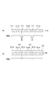
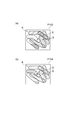
- A) of FIG. 2 is a figure which shows the relationship between a direct conversion type
- B) of FIG. 2 is a figure which shows the relationship between an indirect conversion type
- FIG. 3 is a block diagram of the X-ray inspection apparatus of FIG.
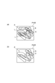
- FIG. 4A shows a soft X-ray transmission image.
- FIG. 4B is a diagram showing a hard X-ray transmission image.
- FIG. 5 is a diagram illustrating a processing procedure for generating a processed soft X-ray transmission image.
- FIG. 1 is a configuration diagram of an X-ray inspection apparatus according to an embodiment.
- A) of FIG. 2 is a figure which shows the relationship between a direct conversion type
- B) of FIG. 2 is a figure which shows the
- FIG. 6 is a diagram illustrating an enlarged post-processing soft X-ray transmission image.
- FIG. 7 is a diagram showing a processed post-process soft X-ray transmission image.
- FIG. 8A is a diagram illustrating an image in which the post-processing soft X-ray transmission image and the hard X-ray transmission image are superimposed.
- FIG. 8B is a diagram illustrating an image in which the post-processing soft X-ray transmission image and the hard X-ray transmission image are further aligned.
- FIG. 9 is a diagram illustrating luminance histograms of the processed soft X-ray transmission image and the hard X-ray transmission image.
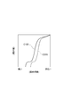
- FIG. 10 is a diagram illustrating luminance histogram integration curves of the processed soft X-ray transmission image and hard X-ray transmission image.
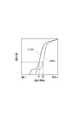
- FIG. 11 is a diagram showing luminance histogram integration curves of the processed soft X-ray transmission image and hard X-ray transmission image.
- FIG. 12 shows a luminance conversion table.
- FIG. 13 is a diagram illustrating a luminance conversion table, a post-complementation luminance conversion table, and a post-complementation smooth luminance conversion table.
- (A) of FIG. 14 is a figure which shows a soft X-ray transmission image after a process.
- FIG. 14B shows a soft X-ray transmission image after luminance conversion.
- FIG. 14 shows a soft X-ray transmission image after luminance conversion.
- FIG. 15 is a diagram showing luminance histograms of the processed soft X-ray transmission image, the hard X-ray transmission image, and the soft X-ray transmission image after luminance conversion.
- A) of FIG. 16 is a figure which shows the soft X-ray transmission image after a process by which luminance conversion was carried out.
- FIG. 16B shows a hard X-ray transmission image.
- C) of FIG. 16 is a figure which shows a result image.
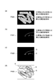
- A) of FIG. 17 is a figure which shows a result image.
- FIG. 17B shows a noise-removed image.
- FIG. 17C shows a binarized image.
- FIG. 17D shows a final image.
- FIG. 18 is a diagram illustrating luminance histograms of the processed soft X-ray transmission image and the hard X-ray transmission image in the modified example.
- the X-ray inspection apparatus 100 includes a transport unit 500, an X-ray irradiation unit 200, an X-ray detection unit 300, and an image processing unit 400.
- the X-ray inspection apparatus 100 detects foreign matter contained in the inspection object A (for example, a plurality of sausages in a bag) using X-ray transparency.
- the transport unit 500 transports the inspection object A.
- Various transport mechanisms such as a belt conveyor, a top chain conveyor, and a rotary table can be applied to the transport unit 500.
- the X-ray irradiation unit 200 irradiates the inspection object A conveyed by the conveyance unit 500 with X-rays.
- the X-rays irradiated from the X-ray irradiation unit 200 include soft X-rays (first energy band X-rays) and hard X-rays (second energy band X-rays).
- the X-ray detection unit 300 detects X-rays irradiated on the inspection object A conveyed by the conveyance unit 500.
- the X-ray detection unit 300 includes a direct conversion X-ray detector 310, an indirect conversion X-ray detector 320, and a filter 350.
- the direct conversion X-ray detector 310 is arranged to face the X-ray irradiation unit 200 with the transport unit 500 interposed therebetween, and detects soft X-rays.
- the indirect conversion X-ray detector 320 is disposed so as to face the X-ray irradiation unit 200 with the conveyance unit 500 and the direct conversion X-ray detector 310 interposed therebetween, and detects hard X-rays.
- the filter 350 is disposed between the direct conversion X-ray detector 310 and the indirect conversion X-ray detector 320 and absorbs X-rays in an energy band between soft X-rays and hard X-rays.
- the direct conversion X-ray detector 310 has a plurality of direct conversion X-ray detection element arrays 311.
- Each direct conversion X-ray detection element array 311 is a line sensor including a plurality of direct conversion X-ray detection elements 311a arranged in one dimension.
- soft X-rays are converted into electric charges by each direct conversion type X-ray detection element 311a which is a photodiode.
- the plurality of direct conversion X-ray detection element arrays 311 include a conveyance direction D1 of the inspection object A by the conveyance unit 500 and an X-ray irradiation direction D2 by the X-ray irradiation unit 200 (that is, the X-ray irradiation unit 200 and the X-ray detection).
- a plurality of direct conversion type X-ray detection elements 311a are one-dimensionally along a direction (direction orthogonal to both directions in the X-ray inspection apparatus 100) that intersects both directions (directions in which the section 300 faces each other) (see FIG. 1). Are arranged side by side.
- the indirect conversion type X-ray detector 320 has a plurality of indirect conversion type X-ray detection element arrays 321. As shown in FIG. Each indirect conversion type X-ray detection element array 321 has a plurality of indirect conversion type X-ray detection elements 321a arranged in one dimension and a plurality of indirect conversion type X-ray detection elements 321a on the X-ray irradiation unit 200 side. And a scintillator layer 321b disposed. In each indirect conversion type X-ray detection element array 321, hard X-rays are converted into light by the scintillator layer 321b, and light is converted into electric charge by each indirect conversion type X-ray detection element 321a which is a photodiode.
- the plurality of indirect conversion type X-ray detection element arrays 321 have a plurality of directions (see FIG. 1) along a direction intersecting both the transport direction D1 and the irradiation direction D2 (the X-ray inspection apparatus 100 is a direction orthogonal to both directions).
- the indirect conversion type X-ray detection elements 321a are arranged side by side so as to be arranged one-dimensionally.
- the sensitivity is relatively lowered in the direct conversion X-ray detection element 311 a located at both ends in manufacturing. Therefore, as shown in FIG. 2A, in the direct conversion X-ray detector 310, the sensitivity is relatively lowered particularly at the connecting portion between the adjacent direct conversion X-ray detection element arrays 311. Even in the indirect conversion type X-ray detection element array 321, the sensitivity is relatively lowered in the indirect conversion type X-ray detection elements 321a located at both ends in the manufacture. However, as shown in FIG.
- the image processing unit 400 generates an X-ray transmission image of the inspection object A based on the detection signal output from the X-ray detection unit 300, and performs image processing on the X-ray transmission image. Apply.
- the image processing unit 400 includes an image generation unit 401, an edge detection unit 402, a horizontal direction blur unit 403, a synthesis unit 404, an image enlargement / reduction unit 405, an image registration unit 406, a histogram creation unit 407, a histogram integration unit 408, and a luminance conversion table.
- a creation unit 409, a data complementation unit 410, a smoothing unit 411, an image conversion unit 412, a virtual data adjustment unit 413, a division unit 414, a filter unit 415, and a binarization unit 416 are provided.
- the image generation unit 401 generates a soft X-ray transmission image (first X-ray transmission image) of the inspection object A based on the soft X-ray detection signal (first detection signal) output from each direct conversion X-ray detection element array 311. ) P100 is generated, and a hard X-ray transmission image (second X-ray transmission) of the inspected object A based on the hard X-ray detection signal (second detection signal) output from each indirect conversion type X-ray detection element array 321 Image) P200 is generated. As shown in FIG. 4A, the soft X-ray transmission image P100 has a relatively high contrast and is generally dark. Also, as shown in FIG. 4B, the hard X-ray transmission image P200 has a relatively low contrast and is bright overall.
- the contrast between the foreign matter S and the inspection object A is small. This is due to the difference in the X-ray absorption rate between the foreign matter S and the inspection object A.
- the sensitivity is lowered particularly at the connection portion between the adjacent direct conversion X-ray detection element arrays 311. Therefore, as shown in FIG. 4A, the luminance of the image of the inspection object A in the soft X-ray transmission image P100 in the region corresponding to the connection portion along the direction corresponding to the conveyance direction D1.
- a line with reduced brightness that is, a brightness reduction line L appears.
- the image generation unit 401 equalizes the background luminance in the X-ray transmission image acquired in a state where the inspection object A is not conveyed in order to cancel the influence of the luminance reduction line L in the soft X-ray transmission image P100.
- a linear correction process is performed.
- the edge detection unit 402 the horizontal direction blurring unit 403, and the combining unit 404 described below cancel the influence of the luminance reduction line L in the soft X-ray transmission image P100.
- the edge detection unit 402 performs edge detection processing on the soft X-ray transmission image P100 to generate an edge detection image P101. More specifically, the edge detection unit 402 performs linear correction processing on the soft X-ray transmission image P100 to equalize the luminance of the image of the inspection object A and the luminance of the background, and the soft X-ray transmission image P100. Is subjected to edge detection processing, and further, binarization processing and inversion processing are performed on the soft X-ray transmission image P100 to generate an edge detection image P101.
- a Laplacian filter, a Sobel filter, or the like is used for the edge detection process.
- the edge detection image P101 the edge of the inspection object A is removed, and the edge of the foreign object S and the luminance reduction line L that are reversed to white remain. [Horizontal blur]
- the horizontal blurring unit 403 performs a horizontal blurring process along the transport direction D1 on the edge detection image P101 to generate a horizontal blurring image P102.
- the horizontal blurring process along the transport direction D1 is, for example, the direction in which the luminance reduction line L extends for one pixel constituting the edge detection image P101 (that is, the direction corresponding to the transport direction D1). This is a process of setting a pixel region in the longitudinal direction so as to include the one pixel, and setting an average value of luminance values in the pixel region as a luminance value of the one pixel. This is performed on a pixel by pixel basis.
- the horizontal blurring process is a step removal process.
- a horizontal blur filter for example, a horizontal blur filter, a horizontal Gaussian filter, or the like is used.
- a horizontal blur filter for example, a horizontal blur filter, a horizontal Gaussian filter, or the like is used.
- the edge of the foreign matter S is removed, and a luminance reduction line L that is inverted to white remains.
- the synthesis unit 404 synthesizes the soft X-ray transmission image P100 and the horizontal blurred image P102 to generate a processed soft X-ray transmission image (processed X-ray transmission image) P103. More specifically, the synthesis unit 404 adds the luminance values of all the pixels constituting the soft X-ray transmission image P100 and the luminance values of all the pixels constituting the horizontal blurred image P102 between corresponding pixels. In addition, a post-processing soft X-ray transmission image P103 is generated. Thereby, the post-processing soft X-ray transmission image P103 from which the luminance reduction line L is removed is obtained. [Image scaling part]
- the image enlargement / reduction unit 405 matches the sizes of the inspection object A in the processed soft X-ray transmission image P103 and the inspection object A in the hard X-ray transmission image P200.
- X-rays emitted from the X-ray irradiation unit 200 are radiated in a fan shape, and the distance from the X-ray irradiation unit 200 to the direct conversion X-ray detector 310 and the indirect conversion X-ray detection from the X-ray irradiation unit 200 are detected. Since the distance to the instrument 320 is different, the inspected object A in the processed soft X-ray transmission image P103 and the inspected object A in the hard X-ray transmission image P200 are different.
- the inspection object A in the hard X-ray transmission image P200 is slightly larger than the inspection object A in the post-processing soft X-ray transmission image P103. Therefore, the image enlargement / reduction unit 405 enlarges the processed soft X-ray transmission image P103 by the conversion ratio R in the line sensor arrangement direction, as shown in FIG.
- This conversion ratio R is calculated as follows: R1 is the distance from the X-ray irradiation unit 200 to the direct conversion X-ray detector 310, and L2 is the distance from the X-ray irradiation unit 200 to the indirect conversion X-ray detector 320. It is obtained by L2 / L1.
- R1 is the distance from the X-ray irradiation unit 200 to the direct conversion X-ray detector 310
- L2 is the distance from the X-ray irradiation unit 200 to the indirect conversion X-ray detector 320. It is obtained by L2 / L1.
- the image alignment unit 406 aligns the position of the inspection object A in the processed soft X-ray transmission image P103 and the inspection object A in the hard X-ray transmission image P200. Specifically, as shown in FIG. 7, the processed soft X-ray transmission image P103 is moved up, down, left and right, and the difference between the processed soft X-ray transmission image P103 and the hard X-ray transmission image P200 is minimized. It is trying to become.
- the image alignment unit 406 of the present embodiment superimposes both images, calculates the sum of absolute values of the difference in luminance values of both images at each pixel, and automatically aligns the sum so that the sum is minimized. I do. As shown in FIG.
- a histogram creation unit 407 a histogram integration unit 408, a luminance conversion table creation unit 409, a data complementing unit 410, a smoothing unit 411, an image conversion unit 412, a virtual data adjustment unit 413, a division unit 414, and a filter unit described below.
- the histogram creation unit 407 creates a soft X-ray luminance histogram H100 indicating the luminance distribution of the processed soft X-ray transmission image P103 and also generates a hard X-ray luminance histogram H200 indicating the luminance distribution of the hard X-ray transmission image P200. .
- the post-processing soft X-ray transmission image P103 is darker as a whole as compared with the hard X-ray transmission image P200. Therefore, as shown in FIG. Compared to the X-ray luminance histogram H200, it is closer to the left side (pixel light and dark side) in the figure. [Histogram integration section]
- the histogram integration unit 408 integrates the soft X-ray luminance histogram H100 described above to calculate a soft X-ray luminance histogram integration curve C100, and integrates the hard X-ray luminance histogram H200 to integrate the hard X-ray luminance histogram H200.
- An X-ray luminance histogram integration curve C200 is calculated.
- the luminance conversion table creation unit 409 compares the soft X-ray luminance histogram integrated curve C100 and the hard X-ray luminance histogram integrated curve C200, and matches the soft X-ray luminance histogram integrated curve C100 with the hard X-ray luminance histogram integrated curve C200.
- the processing soft X-ray transmission image P103 and the hard X-ray transmission image P200 do not have a pixel with a low luminance value (dark pixel), the conversion ratio I of the luminance value cannot be obtained. For this reason, as shown in FIG. 12, there is no conversion data in the region S with a low luminance value of the luminance conversion table T100 created by the luminance conversion table creating unit 409 described above. In this case, luminance conversion cannot be performed for a pixel having a low luminance value. Therefore, the data complementing unit 410 complements the virtual conversion data D in the region S having a low luminance value in the luminance conversion table T100 described above.
- the luminance conversion table supplemented with the virtual conversion data D is referred to as “post-complement luminance conversion table T101”.
- the smoothing unit 411 smoothes the complemented luminance conversion table T101.
- the post-complementation smooth luminance conversion table smoothed by the smoothing unit 411 is referred to as “post-complementation smooth luminance conversion table T102”.
- the luminance conversion table T100 before smoothing may not be a non-smooth curve. is there.
- the inspection object A having a luminance distribution different from that of the processed soft X-ray transmission image P103 and the hard X-ray transmission image P200 described above is targeted, appropriate luminance conversion cannot be performed.
- the smoothing unit 411 smoothes the post-complementation luminance conversion table T101 to obtain a generalized luminance conversion table that can correspond to the inspected object A having various luminance distributions, and draws a smooth curve.
- a post-complementation smooth luminance conversion table T102 is acquired.
- the smoothing unit 411 of this embodiment approximates the post-complementation luminance conversion table T101 with a quadratic function, and A post-complementation smooth luminance conversion table T102 is acquired.
- the image conversion unit 412 performs luminance conversion of the processed soft X-ray transmission image P103 on the basis of the post-complementation smooth luminance conversion table T102, and after luminance conversion A soft X-ray transmission image P104 is acquired.
- the virtual data adjustment unit 413 has a minimum sum of differences between the luminance values of the luminance distribution of the soft X-ray transmission image P104 after luminance conversion and the luminance values of the luminance distribution of the hard X-ray transmission image P200 ( The value of the virtual conversion data D used to obtain the post-complementation smooth luminance conversion table T102 is adjusted so that the least square method is obtained.
- the optimized post-complementation smooth luminance conversion table T102 can be acquired, and the luminance of the post-luminance-converted soft X-ray transmission image P104 and the luminance of the hard X-ray transmission image P200 that have been subjected to luminance conversion by the table T102. Substantially coincides with each other, so that the inspection object A can be erased.
- the optimized post-complementation smooth luminance conversion table T102 is stored in a storage unit (not shown) of the image processing unit 400. [Division part]
- the division unit 414 obtains the luminance value of the post-luminance-converted soft X-ray transmission image P104 (see FIG. 16A) that has been subjected to luminance conversion using the optimized post-complementation smoothed luminance conversion table T102.
- the luminance value of the hard X-ray transmission image P200 (see (b) of FIG. 16) is divided by each pixel to erase the inspection object A.
- the inspection object A may be erased by calculating the difference between the luminance value of each pixel of the soft X-ray transmission image P104 after luminance conversion and the luminance value of each pixel of the hard X-ray transmission image P200.
- the division unit 414 of the present embodiment performs the cancellation of the inspection object A by performing the division.
- the image processing unit 400 can only hold an integer, and thus almost all the calculation results are 1.
- the calculation result is a value such as 1.01, 1.11, 1.21. Therefore, the dividing unit 414 outputs the result image P300 (see FIG. 16C) in which the inspection object A is erased by multiplying the result obtained by dividing the luminance values of both images by 100 times.
- the result image P300 is subjected to a process of offsetting the luminance value by 100 after the process by the filter unit 415 described later. As a result, it is possible to obtain a result image P300 in which the foreign matter S having a brightness value different from that of the region other than the foreign matter S appears.
- the filter unit 415 is provided to remove random noise included in the result image P300.
- the X-ray transmission image includes random noise
- the result image P300 (see FIG. 17A) obtained by deleting the inspection object A also includes the random noise.
- the filter unit 415 of the present embodiment uses a Gaussian filter.
- the luminance value is offset by 100 as described above, thereby extracting a region where the foreign matter S is present. Since the number of digits of the integer value can be reduced, high-speed processing can be performed with a simple arithmetic processing device.
- the noise-removed image P301 (see FIG. 17B) from which noise has been removed by the filter unit 415 is entirely dark (substantially black), but in reality, the region of the foreign matter S is A data value different from that of the region other than the foreign matter S (substantially black) is held. [Binarization part]
- the noise-removed image P301 from which noise has been removed by the filter unit 415 is binarized by the binarizing unit 416 using a certain value as a threshold value. Thereby, the binarized image P302 (see FIG. 17C) from which only the foreign matter S is extracted can be acquired. Thereafter, the image processing unit 400 superimposes the binarized image P302 and the hard X-ray transmission image P200 to create a final image P400 (see FIG. 17D).
- the binarized image P302 and the hard X-ray transmission image P200 are superimposed, but the binarization image P302 and the soft X-ray transmission image P100 may naturally be superimposed.
- the image generation unit 401 generates a soft X-ray transmission image P100 of the inspection object A based on the soft X-ray detection signal output from each direct conversion X-ray detection element array 311 and each indirect conversion type.
- a hard X-ray transmission image P200 of the inspection object A is generated based on the hard X-ray detection signal output from the X-ray detection element array 321.
- the edge detection unit 402 performs edge detection processing on the soft X-ray transmission image P100 to generate an edge detection image P101.
- the horizontal blur unit 403 performs a horizontal blur process on the edge detection image P101 to generate a horizontal blur image P102.
- the synthesizing unit 404 synthesizes the soft X-ray transmission image and the horizontal blurred image P102 to generate a processed soft X-ray transmission image P103.
- the image enlargement / reduction unit 405 matches the sizes of the inspection object A in the processed soft X-ray transmission image P103 and the inspection object A in the hard X-ray transmission image P200.
- the image alignment unit 406 aligns the positions of the inspection object A in the processed soft X-ray transmission image P103 and the inspection object A in the hard X-ray transmission image P200. Note that enlargement and movement of these images can be realized by affine transformation.
- the image conversion unit 412 performs luminance conversion of the post-processing soft X-ray transmission image P103 based on the post-complementation smooth luminance conversion table T102 stored in the storage unit, and the luminance conversion post-luminance conversion soft X-ray transmission image P104. Is generated.
- the division unit 414 divides the luminance value of the soft X-ray transmission image P104 after luminance conversion and the luminance value of the hard X-ray transmission image P200 for each pixel, and the inspection object A is erased.
- a result image P300 is generated.
- the filter unit 415 removes random noise included in the result image P300 and generates a noise-removed image P301.
- the binarization unit 416 binarizes the noise-removed image P301 to generate a binarized image P302.
- the image processing unit 400 generates a final image P400 by superimposing the binarized image P302 and the hard X-ray transmission image P200, and detects the foreign matter S included in the inspection object A.
- a plurality of direct conversion X-ray detection element arrays 311 that convert soft X-rays into electric charges are used, and the image processing unit 400 performs edge detection processing on the soft X-ray transmission image P100 and performs edge detection.
- a detection image P101 is generated, the edge detection image P101 is subjected to a horizontal blurring process to generate a horizontal blurring image P102, and the soft X-ray transmission image P100 and the horizontal blurring image P102 are synthesized and processed soft X-rays.
- a transparent image P103 is generated.
- the luminance reduction line L that appears due to the decrease in sensitivity at the connection portion between the adjacent direct conversion X-ray detection element arrays 311 can be removed in the post-processing soft X-ray transmission image P103. Therefore, according to the X-ray inspection apparatus 100, the foreign matter S can be accurately detected using the plurality of direct conversion type X-ray detection element arrays 311 even when the thick inspection object A is an inspection target. it can.
- the X-ray inspection apparatus 100 by acquiring the post-processing soft X-ray transmission image P103, a material that is difficult to absorb hard X-rays and easily absorbs soft X-rays (for example, glass, rubber, etc.). It is possible to detect the foreign matter S made of metal, light metal such as aluminum) with high accuracy.
- the image processing unit 400 uses the soft X-ray transmission image P100 of the inspection object A generated based on the soft X-ray detection signal output from the direct conversion X-ray detection element array 311. Then, the processed soft X-ray transmission image P103 is generated. Then, the image processing unit 400 transmits the processed soft X-ray transmission image P103 and the hard X-ray transmission of the object A generated based on the hard X-ray detection signal output from the indirect conversion X-ray detection element array 321. The final image P400 is generated by combining the image P200, and the foreign matter S included in the inspection object A is detected. As described above, by using the indirect conversion X-ray detection element array 321 together with the direct conversion X-ray detection element array 311, the foreign matter S can be detected with higher accuracy.
- the X-ray inspection apparatus 100 by using the hard X-ray transmission image P200 together with the processed soft X-ray transmission image P103, a material that hardly absorbs hard X-rays and easily absorbs soft X-rays (for example, It is possible to detect the foreign matter S made of a non-metal such as glass or rubber, or a light metal such as aluminum. [Modification]
- the image processing unit 400 includes the soft X-ray transmission image P100 of the inspection object A generated based on the soft X-ray detection signal output from the direct conversion X-ray detection element array 311 and the indirect conversion X-ray detection.
- the hard X-ray transmission image P200 of the inspection object A generated based on the hard X-ray detection signal output from the element array 321 is combined to generate a composite X-ray transmission image, and the combined X-ray transmission image is generated.
- An edge detection process and a horizontal blurring process are performed to generate a horizontal blurring image, and the synthesized X-ray transmission image and the horizontal blurring image are combined to generate a processed X-ray transmission image as a final image P400.
- the foreign matter S contained in the object A may be detected. Also in this case, the foreign substance S can be detected with higher accuracy by using the indirect conversion type X-ray detection element array 321 together with the direct conversion type X-ray detection element array 311.
- the foreign matter S included in the inspection object A may be detected using one of the soft X-ray transmission image P100 and the hard X-ray transmission image P200, or the weight The foreign matter S included in the inspection object A may be detected using both the soft X-ray transmission image P100 and the hard X-ray transmission image P200 while making adjustments.
- the X-ray inspection apparatus 100 may not include the indirect conversion X-ray detector 320 and may detect the foreign matter S included in the inspection object A using only the soft X-ray transmission image P100.
- the direct conversion X-ray detection element array 311 detects X-rays in the first energy band
- the indirect conversion X-ray detection element array 321 has a second energy band larger than the first energy band.
- the direct conversion type X-ray detection element array 311 is not limited to detecting soft X-rays
- the indirect conversion type X-ray detection element array 321 detects hard X-rays. It is not limited to things.
- the image processing unit 400 may include the following image brightness adjustment unit. That is, as shown in FIG. 18, the soft X-ray luminance histogram H100a indicating the luminance distribution of the processed soft X-ray transmission image P103 is compared with the hard X-ray luminance histogram H200 indicating the luminance distribution of the hard X-ray transmission image P200. May become narrower.
- the image luminance adjustment unit expands the luminance distribution of the post-processing soft X-ray transmission image P103 and performs soft X-ray luminance histogram H100a in order to accurately perform the subsequent adjustment (see FIG. 15). Is converted into a soft X-ray luminance histogram H100.
- the histogram expansion process and the histogram flattening process disclosed in the Internet ⁇ http://codezine.jp/article/detail/214> [October 5, 2015 search] can be used.
- SYMBOLS 100 ... X-ray inspection apparatus, 200 ... X-ray irradiation part, 300 ... X-ray detection part, 311 ... Direct conversion type
Abstract
Provided is an x-ray examination device comprising a conveyance unit, an x-ray emission unit, an x-ray detection unit, and an image processing unit. An x-ray detection unit has a plurality of direct conversion-type x-ray detection element arrays which are disposed side-by-side in rows along a direction orthogonal to both the direction in which an examination object is conveyed by the conveyance unit and the direction in which x-rays are emitted by the x-ray emission unit. The image processing unit includes the following: an edge detection unit that carries out edge detection processing on an x-ray transmission image to generate an edge detected image; a horizontal direction gradation unit that carries out horizontal direction gradation processing on the edge detected image to generate a horizontal direction gradation image; and a synthesizing unit that synthesizes the x-ray transmission image and the horizontal direction gradation image to generate a post-processing x-ray transmission image.
Description
本開示は、X線検査装置に関する。
This disclosure relates to an X-ray inspection apparatus.
X線の透過性を利用して被検査物に含まれる異物を検出するX線検査装置として、X線を電荷に変換する直接変換型X線検出素子アレイを備えるものが知られている(例えば、特許文献1参照)。直接変換型X線検出素子アレイは、例えば、軟X線に対して高い感度を有するため、硬X線を吸収し難く且つ軟X線を吸収し易い材料(例えば、ガラス、ゴム等の非金属、アルミニウム等の軽金属等)からなる異物を検出する場合に有効である。
As an X-ray inspection apparatus that detects foreign matter contained in an inspection object using X-ray transparency, an apparatus including a direct conversion X-ray detection element array that converts X-rays into electric charges is known (for example, , See Patent Document 1). The direct conversion X-ray detection element array has a high sensitivity to soft X-rays, for example, and therefore is difficult to absorb hard X-rays and easily absorbs soft X-rays (for example, non-metal such as glass and rubber). It is effective when detecting foreign substances made of light metals such as aluminum.
上述したようなX線検査装置では、複数の直接変換型X線検出素子アレイが、搬送部による被検査物の搬送方向及びX線照射部によるX線の照射方向の両方向に交差する方向に沿って並設される場合がある。その場合、隣り合う直接変換型X線検出素子アレイ同士の接続部において感度が低下するおそれがある。隣り合う直接変換型X線検出素子アレイ同士の接続部において感度が低下していると、X線透過画像中の被検査物の像のうち当該接続部に対応した領域に、搬送方向に相当する方向に沿って輝度が低下したラインが現れる(以下、当該ラインを「輝度低下ライン」という)。
In the X-ray inspection apparatus as described above, the plurality of direct conversion X-ray detection element arrays are along a direction intersecting both the transport direction of the inspection object by the transport unit and the X-ray irradiation direction by the X-ray irradiation unit. May be installed side by side. In that case, there is a possibility that the sensitivity is lowered at the connection portion between the adjacent direct conversion X-ray detection element arrays. If the sensitivity is reduced at the connection portion between the adjacent direct conversion type X-ray detection element arrays, the region corresponding to the connection portion in the image of the inspection object in the X-ray transmission image corresponds to the transport direction. A line whose luminance decreases along the direction appears (hereinafter, the line is referred to as a “luminance decreasing line”).
X線透過画像において輝度低下ラインの影響をキャンセルするための手段として、被検査物が搬送されていない状態で取得されたX線透過画像において背景の輝度を均一化する線形補正処理(キャリブレーション処理)がある。しかし、被検査物のX線吸収特性は厳密には線形でないため、食肉のような厚い被検査物を検査対象とする場合、線形補正処理を実施しただけでは、X線透過画像において輝度低下ラインの影響をキャンセルすることは困難である。
As a means for canceling the influence of the luminance reduction line in the X-ray transmission image, a linear correction process (calibration process) for making the background luminance uniform in the X-ray transmission image acquired in a state where the inspection object is not conveyed ) However, since the X-ray absorption characteristic of the inspection object is not strictly linear, when a thick inspection object such as meat is to be inspected, the luminance reduction line in the X-ray transmission image is obtained only by performing linear correction processing. It is difficult to cancel the effects of
そこで、本開示は、厚い被検査物を検査対象とする場合であっても、複数の直接変換型X線検出素子アレイを用いて異物を精度良く検出することができるX線検査装置を提供することを目的とする。
Therefore, the present disclosure provides an X-ray inspection apparatus capable of accurately detecting foreign matter using a plurality of direct conversion X-ray detection element arrays even when a thick inspection object is an inspection object. For the purpose.
本開示の一形態に係るX線検査装置は、被検査物を搬送する搬送部と、搬送部によって搬送される被検査物にX線を照射するX線照射部と、搬送部によって搬送される被検査物に照射されたX線を検出するX線検出部と、X線検出部から出力された検出信号に基づいて被検査物のX線透過画像を生成し、X線透過画像に画像処理を施す画像処理部と、を備え、X線検出部は、搬送部による被検査物の搬送方向及びX線照射部によるX線の照射方向の両方向に交差する方向に沿って並設され、第1エネルギー帯のX線を電荷に変換する複数の直接変換型X線検出素子アレイを有し、画像処理部は、X線透過画像にエッジ検出処理を施してエッジ検出画像を生成するエッジ検出部と、エッジ検出画像に、搬送方向に沿っての水平方向ぼかし処理を施して水平方向ぼかし画像を生成する水平方向ぼかし部と、X線透過画像と水平方向ぼかし画像とを合成して処理後X線透過画像を生成する合成部と、を有する。
An X-ray inspection apparatus according to an embodiment of the present disclosure is transported by a transport unit that transports an inspection object, an X-ray irradiation unit that irradiates the inspection object transported by the transport unit, and a transport unit. An X-ray detection unit that detects X-rays irradiated on the inspection object, and an X-ray transmission image of the inspection object are generated based on a detection signal output from the X-ray detection unit, and image processing is performed on the X-ray transmission image An X-ray detection unit arranged in parallel along a direction intersecting both the conveyance direction of the inspection object by the conveyance unit and the X-ray irradiation direction by the X-ray irradiation unit, An edge detection unit that includes a plurality of direct conversion X-ray detection element arrays that convert X-rays in one energy band into electric charges, and the image processing unit generates an edge detection image by performing edge detection processing on the X-ray transmission image And horizontal blurring along the transport direction for edge detection images Subjecting has a horizontal blur unit for generating a horizontal blur images, a synthesizing unit for generating a combined and processed X-ray transmission image and an X-ray transmission image and the horizontal blurred image, the by.
このX線検査装置では、第1エネルギー帯のX線を電荷に変換する複数の直接変換型X線検出素子アレイが用いられ、画像処理部が、X線透過画像にエッジ検出処理を施してエッジ検出画像を生成し、エッジ検出画像に水平方向ぼかし処理を施して水平方向ぼかし画像を生成し、X線透過画像と水平方向ぼかし画像とを合成して処理後X線透過画像を生成する。これにより、隣り合う直接変換型X線検出素子アレイ同士の接続部における感度の低下に起因して出現する輝度低下ラインを、処理後X線透過画像において除去することができる。よって、このX線検査装置によれば、厚い被検査物を検査対象とする場合であっても、複数の直接変換型X線検出素子アレイを用いて異物を精度良く検出することができる。
In this X-ray inspection apparatus, a plurality of direct-conversion X-ray detection element arrays that convert X-rays in the first energy band into electric charges are used, and the image processing unit performs edge detection processing on the X-ray transmission image and performs edge detection. A detection image is generated, a horizontal blur process is performed on the edge detection image to generate a horizontal blur image, and an X-ray transmission image and a horizontal blur image are synthesized to generate a processed X-ray transmission image. As a result, it is possible to remove in the post-process X-ray transmission image a luminance reduction line that appears due to a reduction in sensitivity at the connection portion between adjacent direct conversion type X-ray detection element arrays. Therefore, according to this X-ray inspection apparatus, even when a thick inspection object is to be inspected, a foreign object can be detected with high accuracy using a plurality of direct conversion X-ray detection element arrays.
本開示の一形態に係るX線検査装置では、第1エネルギー帯のX線は、軟X線であってもよい。これにより、硬X線を吸収し難く且つ軟X線を吸収し易い材料(例えば、ガラス、ゴム等の非金属、アルミニウム等の軽金属等)からなる異物を精度良く検出することができる。
In the X-ray inspection apparatus according to an aspect of the present disclosure, the X-ray in the first energy band may be a soft X-ray. Thereby, it is possible to accurately detect a foreign substance made of a material that hardly absorbs hard X-rays and easily absorbs soft X-rays (for example, non-metal such as glass and rubber, light metal such as aluminum).
本開示の一形態に係るX線検査装置では、X線検出部は、搬送部による被検査物の搬送方向及びX線照射部によるX線の照射方向の両方向に交差する方向に沿って並設され、第1エネルギー帯よりも大きい第2エネルギー帯のX線を光に変換して当該光を電荷に変換する間接変換型X線検出素子アレイを更に有し、画像処理部は、直接変換型X線検出素子アレイから出力された第1検出信号に基づいて生成した被検査物の第1X線透過画像をX線透過画像として、処理後X線透過画像を生成し、処理後X線透過画像と、間接変換型X線検出素子アレイから出力された第2検出信号に基づいて生成した被検査物の第2X線透過画像と、を合成してもよい。
In the X-ray inspection apparatus according to an aspect of the present disclosure, the X-ray detection unit is arranged in parallel along a direction intersecting both the conveyance direction of the inspection object by the conveyance unit and the X-ray irradiation direction by the X-ray irradiation unit. And an indirect conversion type X-ray detection element array that converts X-rays in a second energy band larger than the first energy band into light and converts the light into electric charges, and the image processing unit includes a direct conversion type A processed X-ray transmission image is generated by using the first X-ray transmission image of the inspection object generated based on the first detection signal output from the X-ray detection element array as an X-ray transmission image, and the processed X-ray transmission image is generated. And a second X-ray transmission image of the inspection object generated based on the second detection signal output from the indirect conversion type X-ray detection element array may be combined.
本開示の一形態に係るX線検査装置では、X線検出部は、搬送部による被検査物の搬送方向及びX線照射部によるX線の照射方向の両方向に交差する方向に沿って並設され、第1エネルギー帯よりも大きい第2エネルギー帯のX線を光に変換して当該光を電荷に変換する間接変換型X線検出素子アレイを更に有し、画像処理部は、直接変換型X線検出素子アレイから出力された第1検出信号に基づいて生成した被検査物の第1X線透過画像と、間接変換型X線検出素子アレイから出力された第2検出信号に基づいて生成した被検査物の第2X線透過画像と、を合成して、合成X線透過画像を生成し、合成X線透過画像をX線透過画像として、処理後X線透過画像を生成してもよい。
In the X-ray inspection apparatus according to an aspect of the present disclosure, the X-ray detection unit is arranged in parallel along a direction intersecting both the conveyance direction of the inspection object by the conveyance unit and the X-ray irradiation direction by the X-ray irradiation unit. And an indirect conversion type X-ray detection element array that converts X-rays in a second energy band larger than the first energy band into light and converts the light into electric charges, and the image processing unit includes a direct conversion type Generated based on the first X-ray transmission image of the inspection object generated based on the first detection signal output from the X-ray detection element array and the second detection signal output from the indirect conversion X-ray detection element array The processed X-ray transmission image may be generated by combining the second X-ray transmission image of the inspection object to generate a combined X-ray transmission image and using the combined X-ray transmission image as the X-ray transmission image.
このように、第1エネルギー帯よりも大きい第2エネルギー帯のX線を光に変換して当該光を電荷に変換する間接変換型X線検出素子アレイを直接変換型X線検出素子アレイと共に用いることで、異物をより精度良く検出することができる。
Thus, an indirect conversion type X-ray detection element array that converts X-rays in the second energy band larger than the first energy band into light and converts the light into electric charge is used together with the direct conversion type X-ray detection element array. As a result, the foreign matter can be detected with higher accuracy.
本開示の一形態に係るX線検査装置では、第2エネルギー帯のX線は、硬X線であってもよい。硬X線による被検査物のX線透過画像を用いることで、硬X線を吸収し難く且つ軟X線を吸収し易い材料(例えば、ガラス、ゴム等の非金属、アルミニウム等の軽金属等)からなる異物をより精度良く検出することができる。
In the X-ray inspection apparatus according to an aspect of the present disclosure, the X-ray in the second energy band may be a hard X-ray. Materials that are hard to absorb hard X-rays and easy to absorb soft X-rays by using X-ray transmission images of the object to be inspected by hard X-rays (for example, nonmetals such as glass and rubber, light metals such as aluminum, etc.) It is possible to detect the foreign matter consisting of more accurately.
本開示によれば、厚い被検査物を検査対象とする場合であっても、複数の直接変換型X線検出素子アレイを用いて異物を精度良く検出することができるX線検査装置を提供することが可能となる。
According to the present disclosure, there is provided an X-ray inspection apparatus capable of accurately detecting foreign matter using a plurality of direct conversion X-ray detection element arrays even when a thick inspection object is an inspection target. It becomes possible.
以下、本開示の実施形態について、図面を参照して詳細に説明する。なお、各図において同一又は相当部分には同一符号を付し、重複する説明を省略する。
Hereinafter, embodiments of the present disclosure will be described in detail with reference to the drawings. In addition, in each figure, the same code | symbol is attached | subjected to the same or an equivalent part, and the overlapping description is abbreviate | omitted.
図1に示されるように、X線検査装置100は、搬送部500と、X線照射部200と、X線検出部300と、画像処理部400と、を備えている。X線検査装置100は、X線の透過性を利用して被検査物A(例えば、袋入りの複数のソーセージ等)に含まれる異物を検出する。
[搬送部] As shown in FIG. 1, theX-ray inspection apparatus 100 includes a transport unit 500, an X-ray irradiation unit 200, an X-ray detection unit 300, and an image processing unit 400. The X-ray inspection apparatus 100 detects foreign matter contained in the inspection object A (for example, a plurality of sausages in a bag) using X-ray transparency.
[Transport section]
[搬送部] As shown in FIG. 1, the
[Transport section]
搬送部500は、被検査物Aを搬送する。搬送部500には、ベルトコンベア、トップチェーンコンベア、回転テーブル等、様々な搬送機構を適用することが可能である。
[X線照射部] Thetransport unit 500 transports the inspection object A. Various transport mechanisms such as a belt conveyor, a top chain conveyor, and a rotary table can be applied to the transport unit 500.
[X-ray irradiation part]
[X線照射部] The
[X-ray irradiation part]
X線照射部200は、搬送部500によって搬送される被検査物AにX線を照射する。X線照射部200から照射されるX線には、軟X線(第1エネルギー帯のX線)及び硬X線(第2エネルギー帯のX線)が含まれている。
[X線検出部] TheX-ray irradiation unit 200 irradiates the inspection object A conveyed by the conveyance unit 500 with X-rays. The X-rays irradiated from the X-ray irradiation unit 200 include soft X-rays (first energy band X-rays) and hard X-rays (second energy band X-rays).
[X-ray detector]
[X線検出部] The
[X-ray detector]
X線検出部300は、搬送部500によって搬送される被検査物Aに照射されたX線を検出する。X線検出部300は、直接変換型X線検出器310と、間接変換型X線検出器320と、フィルタ350と、を備えている。直接変換型X線検出器310は、搬送部500を挟んでX線照射部200と対向するように配置されており、軟X線を検出する。間接変換型X線検出器320は、搬送部500及び直接変換型X線検出器310を挟んでX線照射部200と対向するように配置されており、硬X線を検出する。フィルタ350は、直接変換型X線検出器310と間接変換型X線検出器320との間に配置されており、軟X線と硬X線との間のエネルギー帯のX線を吸収する。
The X-ray detection unit 300 detects X-rays irradiated on the inspection object A conveyed by the conveyance unit 500. The X-ray detection unit 300 includes a direct conversion X-ray detector 310, an indirect conversion X-ray detector 320, and a filter 350. The direct conversion X-ray detector 310 is arranged to face the X-ray irradiation unit 200 with the transport unit 500 interposed therebetween, and detects soft X-rays. The indirect conversion X-ray detector 320 is disposed so as to face the X-ray irradiation unit 200 with the conveyance unit 500 and the direct conversion X-ray detector 310 interposed therebetween, and detects hard X-rays. The filter 350 is disposed between the direct conversion X-ray detector 310 and the indirect conversion X-ray detector 320 and absorbs X-rays in an energy band between soft X-rays and hard X-rays.
図2の(a)に示されるように、直接変換型X線検出器310は、複数の直接変換型X線検出素子アレイ311を有している。各直接変換型X線検出素子アレイ311は、1次元に配列された複数の直接変換型X線検出素子311aを含むラインセンサである。各直接変換型X線検出素子アレイ311では、フォトダイオードである各直接変換型X線検出素子311aによって軟X線が電荷に変換される。複数の直接変換型X線検出素子アレイ311は、搬送部500による被検査物Aの搬送方向D1及びX線照射部200によるX線の照射方向D2(すなわち、X線照射部200とX線検出部300とが互いに対向する方向)の両方向に交差する方向(X線検査装置100では、両方向に直交する方向)に沿って(図1参照)複数の直接変換型X線検出素子311aが1次元に配列されるように並設されている。
As shown in FIG. 2A, the direct conversion X-ray detector 310 has a plurality of direct conversion X-ray detection element arrays 311. Each direct conversion X-ray detection element array 311 is a line sensor including a plurality of direct conversion X-ray detection elements 311a arranged in one dimension. In each direct conversion type X-ray detection element array 311, soft X-rays are converted into electric charges by each direct conversion type X-ray detection element 311a which is a photodiode. The plurality of direct conversion X-ray detection element arrays 311 include a conveyance direction D1 of the inspection object A by the conveyance unit 500 and an X-ray irradiation direction D2 by the X-ray irradiation unit 200 (that is, the X-ray irradiation unit 200 and the X-ray detection). A plurality of direct conversion type X-ray detection elements 311a are one-dimensionally along a direction (direction orthogonal to both directions in the X-ray inspection apparatus 100) that intersects both directions (directions in which the section 300 faces each other) (see FIG. 1). Are arranged side by side.
図2の(b)に示されるように、間接変換型X線検出器320は、複数の間接変換型X線検出素子アレイ321を有している。各間接変換型X線検出素子アレイ321は、1次元に配列された複数の間接変換型X線検出素子321aと、複数の間接変換型X線検出素子321aに対してX線照射部200側に配置されたシンチレータ層321bと、を含むラインセンサである。各間接変換型X線検出素子アレイ321では、シンチレータ層321bによって硬X線が光に変換され、フォトダイオードである各間接変換型X線検出素子321aによって光が電荷に変換される。複数の間接変換型X線検出素子アレイ321は、搬送方向D1及び照射方向D2の両方向に交差する方向(X線検査装置100は、両方向に直交する方向)に沿って(図1参照)複数の間接変換型X線検出素子321aが1次元に配列されるように並設されている。
2B, the indirect conversion type X-ray detector 320 has a plurality of indirect conversion type X-ray detection element arrays 321. As shown in FIG. Each indirect conversion type X-ray detection element array 321 has a plurality of indirect conversion type X-ray detection elements 321a arranged in one dimension and a plurality of indirect conversion type X-ray detection elements 321a on the X-ray irradiation unit 200 side. And a scintillator layer 321b disposed. In each indirect conversion type X-ray detection element array 321, hard X-rays are converted into light by the scintillator layer 321b, and light is converted into electric charge by each indirect conversion type X-ray detection element 321a which is a photodiode. The plurality of indirect conversion type X-ray detection element arrays 321 have a plurality of directions (see FIG. 1) along a direction intersecting both the transport direction D1 and the irradiation direction D2 (the X-ray inspection apparatus 100 is a direction orthogonal to both directions). The indirect conversion type X-ray detection elements 321a are arranged side by side so as to be arranged one-dimensionally.
なお、直接変換型X線検出素子アレイ311では、その製造上、両端に位置する直接変換型X線検出素子311aにおいて相対的に感度が低下する。そのため、図2の(a)に示されるように、直接変換型X線検出器310では、特に、隣り合う直接変換型X線検出素子アレイ311同士の接続部において相対的に感度が低下する。間接変換型X線検出素子アレイ321でも、その製造上、両端に位置する間接変換型X線検出素子321aにおいて相対的に感度が低下する。しかし、図2の(b)に示されるように、間接変換型X線検出器320では、隣り合うシンチレータ層321b間において光が行き来すること等により、隣り合う間接変換型X線検出素子アレイ321同士の接続部における相対的な感度の低下は、殆ど問題にならない。
[画像処理部] In the direct conversion X-raydetection element array 311, the sensitivity is relatively lowered in the direct conversion X-ray detection element 311 a located at both ends in manufacturing. Therefore, as shown in FIG. 2A, in the direct conversion X-ray detector 310, the sensitivity is relatively lowered particularly at the connecting portion between the adjacent direct conversion X-ray detection element arrays 311. Even in the indirect conversion type X-ray detection element array 321, the sensitivity is relatively lowered in the indirect conversion type X-ray detection elements 321a located at both ends in the manufacture. However, as shown in FIG. 2 (b), in the indirect conversion type X-ray detector 320, light passes back and forth between adjacent scintillator layers 321b, etc., so that the indirect conversion type X-ray detection element array 321 is adjacent. Decrease in relative sensitivity at the connection between the members hardly causes a problem.
[Image processing unit]
[画像処理部] In the direct conversion X-ray
[Image processing unit]
図3に示されるように、画像処理部400は、X線検出部300から出力された検出信号に基づいて被検査物AのX線透過画像を生成し、そのX線透過画像に画像処理を施す。画像処理部400は、画像生成部401、エッジ検出部402、水平方向ぼかし部403、合成部404、画像拡縮部405、画像位置合わせ部406、ヒストグラム作成部407、ヒストグラム積算部408、輝度変換テーブル作成部409、データ補完部410、平滑化部411、画像変換部412、仮想データ調整部413、除算部414、フィルタ部415及び2値化部416、を有している。
[画像生成部] As shown in FIG. 3, theimage processing unit 400 generates an X-ray transmission image of the inspection object A based on the detection signal output from the X-ray detection unit 300, and performs image processing on the X-ray transmission image. Apply. The image processing unit 400 includes an image generation unit 401, an edge detection unit 402, a horizontal direction blur unit 403, a synthesis unit 404, an image enlargement / reduction unit 405, an image registration unit 406, a histogram creation unit 407, a histogram integration unit 408, and a luminance conversion table. A creation unit 409, a data complementation unit 410, a smoothing unit 411, an image conversion unit 412, a virtual data adjustment unit 413, a division unit 414, a filter unit 415, and a binarization unit 416 are provided.
[Image generator]
[画像生成部] As shown in FIG. 3, the
[Image generator]
画像生成部401は、各直接変換型X線検出素子アレイ311から出力された軟X線検出信号(第1検出信号)に基づいて被検査物Aの軟X線透過画像(第1X線透過画像)P100を生成すると共に、各間接変換型X線検出素子アレイ321から出力された硬X線検出信号(第2検出信号)に基づいて被検査物Aの硬X線透過画像(第2X線透過画像)P200を生成する。図4の(a)に示されるように、軟X線透過画像P100は、相対的にコントラストが高く、全体的に暗くなっている。また、図4の(b)に示されるように、硬X線透過画像P200は、相対的にコントラストが低く、全体的に明るくなっている。更に、図4の(a)及び(b)に示されるように、軟X線透過画像P100における異物Sと被検査物A(被検査物Aの重なりの無い領域)とのコントラストに比べて、硬X線透過画像P200における異物Sと被検査物A(被検査物Aの重なりの無い領域)とのコントラストが、小さくなっている。これは、異物Sと被検査物Aとに、X線吸収率の違いがあることに起因する。
The image generation unit 401 generates a soft X-ray transmission image (first X-ray transmission image) of the inspection object A based on the soft X-ray detection signal (first detection signal) output from each direct conversion X-ray detection element array 311. ) P100 is generated, and a hard X-ray transmission image (second X-ray transmission) of the inspected object A based on the hard X-ray detection signal (second detection signal) output from each indirect conversion type X-ray detection element array 321 Image) P200 is generated. As shown in FIG. 4A, the soft X-ray transmission image P100 has a relatively high contrast and is generally dark. Also, as shown in FIG. 4B, the hard X-ray transmission image P200 has a relatively low contrast and is bright overall. Further, as shown in FIGS. 4A and 4B, compared to the contrast between the foreign matter S and the inspection object A (the area where the inspection object A does not overlap) in the soft X-ray transmission image P100, In the hard X-ray transmission image P200, the contrast between the foreign matter S and the inspection object A (the area where the inspection object A does not overlap) is small. This is due to the difference in the X-ray absorption rate between the foreign matter S and the inspection object A.
上述したように、直接変換型X線検出器310では、特に、隣り合う直接変換型X線検出素子アレイ311同士の接続部において感度が低下している。そのため、図4の(a)に示されるように、軟X線透過画像P100中の被検査物Aの像のうち当該接続部に対応した領域に、搬送方向D1に相当する方向に沿って輝度が低下したライン、すなわち、輝度低下ラインLが現れる。画像生成部401は、軟X線透過画像P100において輝度低下ラインLの影響をキャンセルするために、被検査物Aが搬送されていない状態で取得されたX線透過画像において背景の輝度を均一化する線形補正処理を実施している。しかし、被検査物AのX線吸収特性は厳密には線形でないため、食肉のような厚い被検査物Aを検査対象とすると、画像生成部401が線形補正処理を実施しただけでは、軟X線透過画像P100において輝度低下ラインLの影響をキャンセルすることができない。そこで、以下で説明するエッジ検出部402、水平方向ぼかし部403及び合成部404によって、軟X線透過画像P100において輝度低下ラインLの影響がキャンセルされる。
[エッジ検出部] As described above, in the directconversion X-ray detector 310, the sensitivity is lowered particularly at the connection portion between the adjacent direct conversion X-ray detection element arrays 311. Therefore, as shown in FIG. 4A, the luminance of the image of the inspection object A in the soft X-ray transmission image P100 in the region corresponding to the connection portion along the direction corresponding to the conveyance direction D1. A line with reduced brightness, that is, a brightness reduction line L appears. The image generation unit 401 equalizes the background luminance in the X-ray transmission image acquired in a state where the inspection object A is not conveyed in order to cancel the influence of the luminance reduction line L in the soft X-ray transmission image P100. A linear correction process is performed. However, since the X-ray absorption characteristics of the inspection object A are not strictly linear, if the inspection object is a thick inspection object A such as meat, the soft X The influence of the luminance reduction line L cannot be canceled in the line transmission image P100. Thus, the edge detection unit 402, the horizontal direction blurring unit 403, and the combining unit 404 described below cancel the influence of the luminance reduction line L in the soft X-ray transmission image P100.
[Edge detection unit]
[エッジ検出部] As described above, in the direct
[Edge detection unit]
図5に示されるように、エッジ検出部402は、軟X線透過画像P100にエッジ検出処理を施してエッジ検出画像P101を生成する。より具体的には、エッジ検出部402は、軟X線透過画像P100に、被検査物Aの像の輝度と背景の輝度とを均一化する線形補正処理を施し、当該軟X線透過画像P100にエッジ検出処理を施し、更に、当該軟X線透過画像P100に2値化処理及び反転処理を施して、エッジ検出画像P101を生成する。エッジ検出処理には、例えば、ラプラシアンフィルタ、ソーベルフィルタ等が用いられる。これにより、エッジ検出画像P101では、被検査物Aのエッジが除去され、白に反転させられた異物Sのエッジ及び輝度低下ラインLが残る。
[水平方向ぼかし部] As shown in FIG. 5, theedge detection unit 402 performs edge detection processing on the soft X-ray transmission image P100 to generate an edge detection image P101. More specifically, the edge detection unit 402 performs linear correction processing on the soft X-ray transmission image P100 to equalize the luminance of the image of the inspection object A and the luminance of the background, and the soft X-ray transmission image P100. Is subjected to edge detection processing, and further, binarization processing and inversion processing are performed on the soft X-ray transmission image P100 to generate an edge detection image P101. For the edge detection process, for example, a Laplacian filter, a Sobel filter, or the like is used. As a result, in the edge detection image P101, the edge of the inspection object A is removed, and the edge of the foreign object S and the luminance reduction line L that are reversed to white remain.
[Horizontal blur]
[水平方向ぼかし部] As shown in FIG. 5, the
[Horizontal blur]
図5に示されるように、水平方向ぼかし部403は、エッジ検出画像P101に、搬送方向D1に沿っての水平方向ぼかし処理を施して水平方向ぼかし画像P102を生成する。搬送方向D1に沿っての水平方向ぼかし処理とは、例えば、エッジ検出画像P101を構成する1つの画素に対し、輝度低下ラインLが延在する方向(すなわち、搬送方向D1に相当する方向)を長手方向とする画素領域を当該1つの画素を含むように設定し、当該画素領域における輝度値の平均値を当該1つの画素の輝度値とする処理であり、エッジ検出画像P101を構成する全ての画素に対して画素ごとに実施される。水平方向ぼかし処理は、段差除去処理である。水平方向ぼかし処理には、例えば、水平方向ブラーフィルタ、水平方向ガウシアンフィルタ等が用いられる。これにより、水平方向ぼかし画像P102では、異物Sのエッジが除去され、白に反転させられた輝度低下ラインLが残る。
[合成部] As illustrated in FIG. 5, thehorizontal blurring unit 403 performs a horizontal blurring process along the transport direction D1 on the edge detection image P101 to generate a horizontal blurring image P102. The horizontal blurring process along the transport direction D1 is, for example, the direction in which the luminance reduction line L extends for one pixel constituting the edge detection image P101 (that is, the direction corresponding to the transport direction D1). This is a process of setting a pixel region in the longitudinal direction so as to include the one pixel, and setting an average value of luminance values in the pixel region as a luminance value of the one pixel. This is performed on a pixel by pixel basis. The horizontal blurring process is a step removal process. For the horizontal blurring process, for example, a horizontal blur filter, a horizontal Gaussian filter, or the like is used. As a result, in the horizontally blurred image P102, the edge of the foreign matter S is removed, and a luminance reduction line L that is inverted to white remains.
[Combining section]
[合成部] As illustrated in FIG. 5, the
[Combining section]
図5に示されるように、合成部404は、軟X線透過画像P100と水平方向ぼかし画像P102とを合成して処理後軟X線透過画像(処理後X線透過画像)P103を生成する。より具体的には、合成部404は、軟X線透過画像P100を構成する全ての画素の輝度値と水平方向ぼかし画像P102を構成する全ての画素の輝度値とを、対応する画素間において足し合わせて、処理後軟X線透過画像P103を生成する。これにより、輝度低下ラインLが除去された処理後軟X線透過画像P103が得られる。
[画像拡縮部] As illustrated in FIG. 5, thesynthesis unit 404 synthesizes the soft X-ray transmission image P100 and the horizontal blurred image P102 to generate a processed soft X-ray transmission image (processed X-ray transmission image) P103. More specifically, the synthesis unit 404 adds the luminance values of all the pixels constituting the soft X-ray transmission image P100 and the luminance values of all the pixels constituting the horizontal blurred image P102 between corresponding pixels. In addition, a post-processing soft X-ray transmission image P103 is generated. Thereby, the post-processing soft X-ray transmission image P103 from which the luminance reduction line L is removed is obtained.
[Image scaling part]
[画像拡縮部] As illustrated in FIG. 5, the
[Image scaling part]
画像拡縮部405は、処理後軟X線透過画像P103における被検査物Aと硬X線透過画像P200における被検査物Aとの大きさを合わせる。X線照射部200から照射されるX線は、扇状に放射されると共に、X線照射部200から直接変換型X線検出器310までの距離とX線照射部200から間接変換型X線検出器320までの距離とが異なるので、処理後軟X線透過画像P103における被検査物Aと硬X線透過画像P200における被検査物Aとの大きさが異なる。すなわち、硬X線透過画像P200における被検査物Aが、処理後軟X線透過画像P103における被検査物Aより僅かに大きくなる。そこで、画像拡縮部405は、図6に示されるように、処理後軟X線透過画像P103を変換比Rだけラインセンサの配列方向に拡大する。この変換比Rは、X線照射部200から直接変換型X線検出器310までの距離をL1、X線照射部200から間接変換型X線検出器320までの距離をL2とすると、R=L2/L1で得られる。ここでは、処理後軟X線透過画像P103を拡大する例について説明したが、当然、硬X線透過画像P200をRの逆数(1/R)の比率で縮小してもよい。
[画像位置合わせ部] The image enlargement /reduction unit 405 matches the sizes of the inspection object A in the processed soft X-ray transmission image P103 and the inspection object A in the hard X-ray transmission image P200. X-rays emitted from the X-ray irradiation unit 200 are radiated in a fan shape, and the distance from the X-ray irradiation unit 200 to the direct conversion X-ray detector 310 and the indirect conversion X-ray detection from the X-ray irradiation unit 200 are detected. Since the distance to the instrument 320 is different, the inspected object A in the processed soft X-ray transmission image P103 and the inspected object A in the hard X-ray transmission image P200 are different. That is, the inspection object A in the hard X-ray transmission image P200 is slightly larger than the inspection object A in the post-processing soft X-ray transmission image P103. Therefore, the image enlargement / reduction unit 405 enlarges the processed soft X-ray transmission image P103 by the conversion ratio R in the line sensor arrangement direction, as shown in FIG. This conversion ratio R is calculated as follows: R1 is the distance from the X-ray irradiation unit 200 to the direct conversion X-ray detector 310, and L2 is the distance from the X-ray irradiation unit 200 to the indirect conversion X-ray detector 320. It is obtained by L2 / L1. Here, an example in which the post-processing soft X-ray transmission image P103 is enlarged has been described. Naturally, the hard X-ray transmission image P200 may be reduced at a ratio of the reciprocal of R (1 / R).
[Image alignment section]
[画像位置合わせ部] The image enlargement /
[Image alignment section]
画像位置合わせ部406は、処理後軟X線透過画像P103における被検査物Aと硬X線透過画像P200における被検査物Aとの位置を合わせる。具体的には、図7に示されるように、処理後軟X線透過画像P103を上下左右に移動させて、処理後軟X線透過画像P103と硬X線透過画像P200との差異が最小になるようにしている。本実施形態の画像位置合わせ部406は、両画像を重ね合わせて、各画素において両画像の輝度値の差の絶対値の総和を算出し、その総和が最小となるように自動的に位置合わせを行う。図8の(a)に示されるように、画像位置合わせ部406による位置合わせ前では、被検査物Aのエッジ部分E1及び異物Sのエッジ部分E2が現れる。なお、画像上のエッジ部分が、被検査物Aのエッジ部分E1か、異物Sのエッジ部分E2かは、判別不可能である。そして、図8の(b)に示されるように、画像位置合わせ部406による位置合わせ後では、被検査物A及び異物Sの位置ズレが解消されて、ほぼ黒一色の状態の画像となる。
The image alignment unit 406 aligns the position of the inspection object A in the processed soft X-ray transmission image P103 and the inspection object A in the hard X-ray transmission image P200. Specifically, as shown in FIG. 7, the processed soft X-ray transmission image P103 is moved up, down, left and right, and the difference between the processed soft X-ray transmission image P103 and the hard X-ray transmission image P200 is minimized. It is trying to become. The image alignment unit 406 of the present embodiment superimposes both images, calculates the sum of absolute values of the difference in luminance values of both images at each pixel, and automatically aligns the sum so that the sum is minimized. I do. As shown in FIG. 8A, before the alignment by the image alignment unit 406, an edge portion E1 of the inspection object A and an edge portion E2 of the foreign object S appear. Note that it is impossible to determine whether the edge portion on the image is the edge portion E1 of the inspection object A or the edge portion E2 of the foreign object S. Then, as shown in FIG. 8B, after the alignment by the image alignment unit 406, the positional deviation of the inspection object A and the foreign matter S is eliminated, and the image is almost black.
なお、この図8の(b)の位置合わせ後の画像に示されるように、単に処理後軟X線透過画像P103の拡大及び位置合わせだけでは、異物Sの領域についてもほぼ黒一色になり、異物Sの判別が不可能である。そこで、以下で説明するヒストグラム作成部407、ヒストグラム積算部408、輝度変換テーブル作成部409、データ補完部410、平滑化部411、画像変換部412、仮想データ調整部413、除算部414、フィルタ部415及び2値化部416により、軟X線透過画像P100の画像処理を施すことによって、異物Sの判別を可能にする。
[ヒストグラム作成部] Note that, as shown in the image after alignment in FIG. 8B, the area of the foreign matter S is almost black only by simply enlarging and aligning the processed soft X-ray transmission image P103. The foreign matter S cannot be identified. Therefore, ahistogram creation unit 407, a histogram integration unit 408, a luminance conversion table creation unit 409, a data complementing unit 410, a smoothing unit 411, an image conversion unit 412, a virtual data adjustment unit 413, a division unit 414, and a filter unit described below. By performing image processing of the soft X-ray transmission image P100 by the 415 and the binarization unit 416, the foreign matter S can be discriminated.
[Histogram creation part]
[ヒストグラム作成部] Note that, as shown in the image after alignment in FIG. 8B, the area of the foreign matter S is almost black only by simply enlarging and aligning the processed soft X-ray transmission image P103. The foreign matter S cannot be identified. Therefore, a
[Histogram creation part]
ヒストグラム作成部407は、処理後軟X線透過画像P103の輝度分布を示す軟X線輝度ヒストグラムH100を作成すると共に、硬X線透過画像P200の輝度分布を示す硬X線輝度ヒストグラムH200を作成する。上述したように、処理後軟X線透過画像P103は、硬X線透過画像P200に比べて全体的に暗くなっているので、図9に示されるように、軟X線輝度ヒストグラムH100は、硬X線輝度ヒストグラムH200に比べて、図中の左側(画素明暗が明るい側)に寄っている。
[ヒストグラム積算部] Thehistogram creation unit 407 creates a soft X-ray luminance histogram H100 indicating the luminance distribution of the processed soft X-ray transmission image P103 and also generates a hard X-ray luminance histogram H200 indicating the luminance distribution of the hard X-ray transmission image P200. . As described above, the post-processing soft X-ray transmission image P103 is darker as a whole as compared with the hard X-ray transmission image P200. Therefore, as shown in FIG. Compared to the X-ray luminance histogram H200, it is closer to the left side (pixel light and dark side) in the figure.
[Histogram integration section]
[ヒストグラム積算部] The
[Histogram integration section]
ヒストグラム積算部408は、図10に示されるように、上述した軟X線輝度ヒストグラムH100を積分して軟X線輝度ヒストグラム積算曲線C100を算出すると共に、硬X線輝度ヒストグラムH200を積分して硬X線輝度ヒストグラム積算曲線C200を算出する。
[輝度変換テーブル作成部] As shown in FIG. 10, thehistogram integration unit 408 integrates the soft X-ray luminance histogram H100 described above to calculate a soft X-ray luminance histogram integration curve C100, and integrates the hard X-ray luminance histogram H200 to integrate the hard X-ray luminance histogram H200. An X-ray luminance histogram integration curve C200 is calculated.
[Brightness conversion table creation section]
[輝度変換テーブル作成部] As shown in FIG. 10, the
[Brightness conversion table creation section]
輝度変換テーブル作成部409は、軟X線輝度ヒストグラム積算曲線C100と硬X線輝度ヒストグラム積算曲線C200とを比較して、軟X線輝度ヒストグラム積算曲線C100を硬X線輝度ヒストグラム積算曲線C200に一致又は近似させる輝度変換テーブルT100を作成する。具体的には、図11に示されるように、軟X線輝度ヒストグラム積算曲線C100の積算値I1と、硬X線輝度ヒストグラム積算曲線の積算値I2とが一致する輝度の変換比I=I1/I2を各輝度で求めることにより、図12に示される輝度変換テーブルT100を得る。
[データ補完部] The luminance conversiontable creation unit 409 compares the soft X-ray luminance histogram integrated curve C100 and the hard X-ray luminance histogram integrated curve C200, and matches the soft X-ray luminance histogram integrated curve C100 with the hard X-ray luminance histogram integrated curve C200. Alternatively, the brightness conversion table T100 to be approximated is created. Specifically, as shown in FIG. 11, the luminance conversion ratio I = I1 / where the integrated value I1 of the soft X-ray luminance histogram integrated curve C100 and the integrated value I2 of the hard X-ray luminance histogram integrated curve match. By obtaining I2 for each luminance, the luminance conversion table T100 shown in FIG. 12 is obtained.
[Data completion part]
[データ補完部] The luminance conversion
[Data completion part]
処理後軟X線透過画像P103及び硬X線透過画像P200に輝度値の低い画素(暗い画素)が無い場合には、当該輝度値の変換比Iを求めることができない。そのため、図12に示されるように、上述した輝度変換テーブル作成部409により作成された輝度変換テーブルT100の輝度値の低い領域Sには、変換データが存在しない。この場合、輝度値の低い画素については、輝度変換を行うことができない。そこで、データ補完部410は、上述した輝度変換テーブルT100に、輝度値の低い領域Sにおいて仮想の変換データDを補完する。以下、仮想の変換データDが補完された輝度変換テーブルを、「補完後輝度変換テーブルT101」とする。
[平滑化部] If the processed soft X-ray transmission image P103 and the hard X-ray transmission image P200 do not have a pixel with a low luminance value (dark pixel), the conversion ratio I of the luminance value cannot be obtained. For this reason, as shown in FIG. 12, there is no conversion data in the region S with a low luminance value of the luminance conversion table T100 created by the luminance conversiontable creating unit 409 described above. In this case, luminance conversion cannot be performed for a pixel having a low luminance value. Therefore, the data complementing unit 410 complements the virtual conversion data D in the region S having a low luminance value in the luminance conversion table T100 described above. Hereinafter, the luminance conversion table supplemented with the virtual conversion data D is referred to as “post-complement luminance conversion table T101”.
[Smoothing part]
[平滑化部] If the processed soft X-ray transmission image P103 and the hard X-ray transmission image P200 do not have a pixel with a low luminance value (dark pixel), the conversion ratio I of the luminance value cannot be obtained. For this reason, as shown in FIG. 12, there is no conversion data in the region S with a low luminance value of the luminance conversion table T100 created by the luminance conversion
[Smoothing part]
平滑化部411は、図13に示されるように、補完後輝度変換テーブルT101を平滑化する。以下、この平滑化部411により平滑化された補完後平滑輝度変換テーブルを、「補完後平滑輝度変換テーブルT102」とする。上述した画像生成部401により生成された処理後軟X線透過画像P103及び硬X線透過画像P200の輝度分布が狭い場合等には、平滑化前の輝度変換テーブルT100が滑らかでない曲線でない場合がある。この場合、上述した処理後軟X線透過画像P103及び硬X線透過画像P200とは異なる輝度分布を有する被検査物Aを対象にした場合、妥当な輝度変換が行えない。そのため、平滑化部411は、種々の輝度分布を有する被検査物Aに対応可能な一般化された輝度変換テーブルを取得すべく、補完後輝度変換テーブルT101を平滑化して、滑らかな曲線を描く補完後平滑輝度変換テーブルT102を取得する。実験の結果から、2次関数で近似すれば十分実用的なテーブルを取得し得たことから、本実施形態の平滑化部411は、補完後輝度変換テーブルT101を2次関数で近似して、補完後平滑輝度変換テーブルT102を取得する。
[画像変換部] As shown in FIG. 13, the smoothingunit 411 smoothes the complemented luminance conversion table T101. Hereinafter, the post-complementation smooth luminance conversion table smoothed by the smoothing unit 411 is referred to as “post-complementation smooth luminance conversion table T102”. When the luminance distribution of the processed soft X-ray transmission image P103 and the hard X-ray transmission image P200 generated by the image generation unit 401 described above is narrow, the luminance conversion table T100 before smoothing may not be a non-smooth curve. is there. In this case, when the inspection object A having a luminance distribution different from that of the processed soft X-ray transmission image P103 and the hard X-ray transmission image P200 described above is targeted, appropriate luminance conversion cannot be performed. Therefore, the smoothing unit 411 smoothes the post-complementation luminance conversion table T101 to obtain a generalized luminance conversion table that can correspond to the inspected object A having various luminance distributions, and draws a smooth curve. A post-complementation smooth luminance conversion table T102 is acquired. As a result of the experiment, it was possible to obtain a sufficiently practical table by approximating with a quadratic function. Therefore, the smoothing unit 411 of this embodiment approximates the post-complementation luminance conversion table T101 with a quadratic function, and A post-complementation smooth luminance conversion table T102 is acquired.
[Image converter]
[画像変換部] As shown in FIG. 13, the smoothing
[Image converter]
画像変換部412は、図14の(a)及び(b)に示されるように、補完後平滑輝度変換テーブルT102に基づいて、処理後軟X線透過画像P103の輝度変換を行い、輝度変換後軟X線透過画像P104を取得する。
[仮想データ調整部] As shown in FIGS. 14A and 14B, theimage conversion unit 412 performs luminance conversion of the processed soft X-ray transmission image P103 on the basis of the post-complementation smooth luminance conversion table T102, and after luminance conversion A soft X-ray transmission image P104 is acquired.
[Virtual data adjustment section]
[仮想データ調整部] As shown in FIGS. 14A and 14B, the
[Virtual data adjustment section]
図15に示されるように、輝度変換後軟X線透過画像P104の輝度ヒストグラムH101と、硬X線透過画像P200の硬X線輝度ヒストグラムH200とを比較すると、厳密には一致していない。そこで、この仮想データ調整部413は、輝度変換後軟X線透過画像P104の輝度分布の各輝度値と、硬X線透過画像P200の輝度分布の各輝度値と、の差の総和が最小(最小2乗法)になるように、当該補完後平滑輝度変換テーブルT102を取得するのに用いた仮想の変換データDの値を調整する。これにより、最適化された補完後平滑輝度変換テーブルT102を取得することができ、当該テーブルT102により輝度変換された輝度変換後軟X線透過画像P104の輝度と、硬X線透過画像P200の輝度とが略一致するので、被検査物Aの消し込みが可能となる。なお、この最適化された補完後平滑輝度変換テーブルT102は、画像処理部400の記憶部(図示省略)に格納されている。
[除算部] As shown in FIG. 15, when the luminance histogram H101 of the soft X-ray transmission image P104 after luminance conversion is compared with the hard X-ray luminance histogram H200 of the hard X-ray transmission image P200, they do not exactly match. Therefore, the virtualdata adjustment unit 413 has a minimum sum of differences between the luminance values of the luminance distribution of the soft X-ray transmission image P104 after luminance conversion and the luminance values of the luminance distribution of the hard X-ray transmission image P200 ( The value of the virtual conversion data D used to obtain the post-complementation smooth luminance conversion table T102 is adjusted so that the least square method is obtained. Thereby, the optimized post-complementation smooth luminance conversion table T102 can be acquired, and the luminance of the post-luminance-converted soft X-ray transmission image P104 and the luminance of the hard X-ray transmission image P200 that have been subjected to luminance conversion by the table T102. Substantially coincides with each other, so that the inspection object A can be erased. The optimized post-complementation smooth luminance conversion table T102 is stored in a storage unit (not shown) of the image processing unit 400.
[Division part]
[除算部] As shown in FIG. 15, when the luminance histogram H101 of the soft X-ray transmission image P104 after luminance conversion is compared with the hard X-ray luminance histogram H200 of the hard X-ray transmission image P200, they do not exactly match. Therefore, the virtual
[Division part]
図16に示されるように、除算部414は、最適化された補完後平滑輝度変換テーブルT102により輝度変換された輝度変換後軟X線透過画像P104(図16の(a)参照)の輝度値と、硬X線透過画像P200(図16の(b)参照)の輝度値とを各画素で除算することによって、被検査物Aの消し込みを行う。輝度変換後軟X線透過画像P104の各画素の輝度値と、硬X線透過画像P200の各画素の輝度値との差を求めることによって、被検査物Aの消し込みを行ってもよいが、実験の結果から、除算する方が被検査物Aの消し込み精度が良いことが分かったので、本実施形態の除算部414は、除算を行うことにより、被検査物Aの消し込みを行う。ただし、単純に除算すると、画像処理部400が整数しか保持できない構成となっているので、殆どの演算結果が1となってしまう。例えば、その演算結果は、1.01、1.11、1.21等の値となる。そのため、除算部414は、両画像の輝度値を除算した結果を100倍にして、被検査物Aの消し込みがなされた結果画像P300(図16の(c)参照)を出力する。なお、当該結果画像P300は、後述するフィルタ部415による処理の後に、輝度値を100だけオフセットする処理が行われる。これにより、異物S以外の領域とは異なる輝度値を保持する異物Sが現れた結果画像P300を取得することができる。
[フィルタ部] As shown in FIG. 16, thedivision unit 414 obtains the luminance value of the post-luminance-converted soft X-ray transmission image P104 (see FIG. 16A) that has been subjected to luminance conversion using the optimized post-complementation smoothed luminance conversion table T102. And the luminance value of the hard X-ray transmission image P200 (see (b) of FIG. 16) is divided by each pixel to erase the inspection object A. The inspection object A may be erased by calculating the difference between the luminance value of each pixel of the soft X-ray transmission image P104 after luminance conversion and the luminance value of each pixel of the hard X-ray transmission image P200. From the result of the experiment, it has been found that the division accuracy of the inspection object A is better when the division is performed. Therefore, the division unit 414 of the present embodiment performs the cancellation of the inspection object A by performing the division. . However, if the image is simply divided, the image processing unit 400 can only hold an integer, and thus almost all the calculation results are 1. For example, the calculation result is a value such as 1.01, 1.11, 1.21. Therefore, the dividing unit 414 outputs the result image P300 (see FIG. 16C) in which the inspection object A is erased by multiplying the result obtained by dividing the luminance values of both images by 100 times. The result image P300 is subjected to a process of offsetting the luminance value by 100 after the process by the filter unit 415 described later. As a result, it is possible to obtain a result image P300 in which the foreign matter S having a brightness value different from that of the region other than the foreign matter S appears.
[Filter section]
[フィルタ部] As shown in FIG. 16, the
[Filter section]
フィルタ部415は、当該結果画像P300に含まれるランダムノイズを除去するために設けられている。通常、X線透過画像には、ランダムノイズが含まれており、被検査物Aの消し込みを行った結果画像P300(図17の(a)参照)にも当該ランダムノイズが含まれている。被検査物Aに異物Sが含まれている場合、X線透過画像の異物Sがある領域は、ノイズより大きな値となっているので、本実施形態のフィルタ部415は、ガウシアンフィルタを用いて、細かいノイズを除去すると共に、上述したように輝度値を100だけオフセットすることによって、異物Sがある領域を抽出する。なお、整数値の桁数を減らすことができるので、簡易な演算処理装置で高速処理することができる。また、フィルタ部415によってノイズが除去されたノイズ除去画像P301(図17の(b)参照)は、全体が暗く(ほぼ黒一色に)なっているが、実際には、異物Sの領域は、異物S以外の領域(ほぼ黒一色の)とは異なるデータ値を保持している。
[2値化部] Thefilter unit 415 is provided to remove random noise included in the result image P300. Usually, the X-ray transmission image includes random noise, and the result image P300 (see FIG. 17A) obtained by deleting the inspection object A also includes the random noise. When the inspection object A includes the foreign matter S, the region where the foreign matter S is in the X-ray transmission image has a value larger than the noise. Therefore, the filter unit 415 of the present embodiment uses a Gaussian filter. In addition to removing fine noise, the luminance value is offset by 100 as described above, thereby extracting a region where the foreign matter S is present. Since the number of digits of the integer value can be reduced, high-speed processing can be performed with a simple arithmetic processing device. Further, the noise-removed image P301 (see FIG. 17B) from which noise has been removed by the filter unit 415 is entirely dark (substantially black), but in reality, the region of the foreign matter S is A data value different from that of the region other than the foreign matter S (substantially black) is held.
[Binarization part]
[2値化部] The
[Binarization part]
フィルタ部415によってノイズが除去されたノイズ除去画像P301は、2値化部416により、一定の値を閾値として、2値化される。これにより、異物Sのみが抽出された2値化画像P302(図17の(c)参照)を取得することができる。この後、画像処理部400は、当該2値化画像P302と硬X線透過画像P200とを重ね合わせて、最終画像P400(図17の(d)参照)を作成する。なお、ここでは、2値化画像P302と硬X線透過画像P200とを重ね合わせたが、当然、2値化画像P302と軟X線透過画像P100とを重ね合わせてもよい。
[画像処理部による画像処理方法] The noise-removed image P301 from which noise has been removed by thefilter unit 415 is binarized by the binarizing unit 416 using a certain value as a threshold value. Thereby, the binarized image P302 (see FIG. 17C) from which only the foreign matter S is extracted can be acquired. Thereafter, the image processing unit 400 superimposes the binarized image P302 and the hard X-ray transmission image P200 to create a final image P400 (see FIG. 17D). Here, the binarized image P302 and the hard X-ray transmission image P200 are superimposed, but the binarization image P302 and the soft X-ray transmission image P100 may naturally be superimposed.
[Image processing method by image processing unit]
[画像処理部による画像処理方法] The noise-removed image P301 from which noise has been removed by the
[Image processing method by image processing unit]
まず、画像生成部401が、各直接変換型X線検出素子アレイ311から出力された軟X線検出信号に基づいて被検査物Aの軟X線透過画像P100を生成すると共に、各間接変換型X線検出素子アレイ321から出力された硬X線検出信号に基づいて被検査物Aの硬X線透過画像P200を生成する。続いて、エッジ検出部402が、軟X線透過画像P100にエッジ検出処理を施してエッジ検出画像P101を生成する。続いて、水平方向ぼかし部403が、エッジ検出画像P101に水平方向ぼかし処理を施して水平方向ぼかし画像P102を生成する。続いて、合成部404が、軟X線透過画像と水平方向ぼかし画像P102とを合成して処理後軟X線透過画像P103を生成する。
First, the image generation unit 401 generates a soft X-ray transmission image P100 of the inspection object A based on the soft X-ray detection signal output from each direct conversion X-ray detection element array 311 and each indirect conversion type. A hard X-ray transmission image P200 of the inspection object A is generated based on the hard X-ray detection signal output from the X-ray detection element array 321. Subsequently, the edge detection unit 402 performs edge detection processing on the soft X-ray transmission image P100 to generate an edge detection image P101. Subsequently, the horizontal blur unit 403 performs a horizontal blur process on the edge detection image P101 to generate a horizontal blur image P102. Subsequently, the synthesizing unit 404 synthesizes the soft X-ray transmission image and the horizontal blurred image P102 to generate a processed soft X-ray transmission image P103.
続いて、画像拡縮部405が、処理後軟X線透過画像P103における被検査物Aと硬X線透過画像P200における被検査物Aとの大きさを合わせる。続いて、画像位置合わせ部406が、処理後軟X線透過画像P103における被検査物Aと硬X線透過画像P200における被検査物Aとの位置を合わせる。なお、これらの画像の拡大及び画像の移動は、アフィン変換により実現することができる。続いて、画像変換部412が、記憶部に記憶されていた補完後平滑輝度変換テーブルT102に基づいて処理後軟X線透過画像P103の輝度変換を行って、輝度変換後軟X線透過画像P104を生成する。
Subsequently, the image enlargement / reduction unit 405 matches the sizes of the inspection object A in the processed soft X-ray transmission image P103 and the inspection object A in the hard X-ray transmission image P200. Subsequently, the image alignment unit 406 aligns the positions of the inspection object A in the processed soft X-ray transmission image P103 and the inspection object A in the hard X-ray transmission image P200. Note that enlargement and movement of these images can be realized by affine transformation. Subsequently, the image conversion unit 412 performs luminance conversion of the post-processing soft X-ray transmission image P103 based on the post-complementation smooth luminance conversion table T102 stored in the storage unit, and the luminance conversion post-luminance conversion soft X-ray transmission image P104. Is generated.
続いて、除算部414が、輝度変換後軟X線透過画像P104の輝度値と硬X線透過画像P200の輝度値とを画素ごとに除算して、被検査物Aの消し込みが行われた結果画像P300を生成する。続いて、フィルタ部415が、結果画像P300に含まれるランダムノイズを除去してノイズ除去画像P301を生成する。続いて、2値化部416が、ノイズ除去画像P301を2値化して2値化画像P302を生成する。続いて、画像処理部400が、2値化画像P302と硬X線透過画像P200とを重ね合わせて最終画像P400を生成し、被検査物Aに含まれる異物Sを検出する。
[作用及び効果] Subsequently, thedivision unit 414 divides the luminance value of the soft X-ray transmission image P104 after luminance conversion and the luminance value of the hard X-ray transmission image P200 for each pixel, and the inspection object A is erased. A result image P300 is generated. Subsequently, the filter unit 415 removes random noise included in the result image P300 and generates a noise-removed image P301. Subsequently, the binarization unit 416 binarizes the noise-removed image P301 to generate a binarized image P302. Subsequently, the image processing unit 400 generates a final image P400 by superimposing the binarized image P302 and the hard X-ray transmission image P200, and detects the foreign matter S included in the inspection object A.
[Action and effect]
[作用及び効果] Subsequently, the
[Action and effect]
X線検査装置100では、軟X線を電荷に変換する複数の直接変換型X線検出素子アレイ311が用いられ、画像処理部400が、軟X線透過画像P100にエッジ検出処理を施してエッジ検出画像P101を生成し、エッジ検出画像P101に水平方向ぼかし処理を施して水平方向ぼかし画像P102を生成し、軟X線透過画像P100と水平方向ぼかし画像P102とを合成して処理後軟X線透過画像P103を生成する。これにより、隣り合う直接変換型X線検出素子アレイ311同士の接続部における感度の低下に起因して出現する輝度低下ラインLを、処理後軟X線透過画像P103において除去することができる。よって、X線検査装置100によれば、厚い被検査物Aを検査対象とする場合であっても、複数の直接変換型X線検出素子アレイ311を用いて異物Sを精度良く検出することができる。
In the X-ray inspection apparatus 100, a plurality of direct conversion X-ray detection element arrays 311 that convert soft X-rays into electric charges are used, and the image processing unit 400 performs edge detection processing on the soft X-ray transmission image P100 and performs edge detection. A detection image P101 is generated, the edge detection image P101 is subjected to a horizontal blurring process to generate a horizontal blurring image P102, and the soft X-ray transmission image P100 and the horizontal blurring image P102 are synthesized and processed soft X-rays. A transparent image P103 is generated. Thereby, the luminance reduction line L that appears due to the decrease in sensitivity at the connection portion between the adjacent direct conversion X-ray detection element arrays 311 can be removed in the post-processing soft X-ray transmission image P103. Therefore, according to the X-ray inspection apparatus 100, the foreign matter S can be accurately detected using the plurality of direct conversion type X-ray detection element arrays 311 even when the thick inspection object A is an inspection target. it can.
特に、X線検査装置100によれば、処理後軟X線透過画像P103を取得することにより、硬X線を吸収し難く且つ軟X線を吸収し易い材料(例えば、ガラス、ゴム等の非金属、アルミニウム等の軽金属等)からなる異物Sを精度良く検出することができる。
In particular, according to the X-ray inspection apparatus 100, by acquiring the post-processing soft X-ray transmission image P103, a material that is difficult to absorb hard X-rays and easily absorbs soft X-rays (for example, glass, rubber, etc.). It is possible to detect the foreign matter S made of metal, light metal such as aluminum) with high accuracy.
また、X線検査装置100では、画像処理部400が、直接変換型X線検出素子アレイ311から出力された軟X線検出信号に基づいて生成した被検査物Aの軟X線透過画像P100から、処理後軟X線透過画像P103を生成する。そして、画像処理部400が、処理後軟X線透過画像P103と、間接変換型X線検出素子アレイ321から出力された硬X線検出信号に基づいて生成した被検査物Aの硬X線透過画像P200と、を合成して最終画像P400を生成し、被検査物Aに含まれる異物Sを検出する。このように、間接変換型X線検出素子アレイ321を直接変換型X線検出素子アレイ311と共に用いることで、異物Sをより精度良く検出することができる。
Further, in the X-ray inspection apparatus 100, the image processing unit 400 uses the soft X-ray transmission image P100 of the inspection object A generated based on the soft X-ray detection signal output from the direct conversion X-ray detection element array 311. Then, the processed soft X-ray transmission image P103 is generated. Then, the image processing unit 400 transmits the processed soft X-ray transmission image P103 and the hard X-ray transmission of the object A generated based on the hard X-ray detection signal output from the indirect conversion X-ray detection element array 321. The final image P400 is generated by combining the image P200, and the foreign matter S included in the inspection object A is detected. As described above, by using the indirect conversion X-ray detection element array 321 together with the direct conversion X-ray detection element array 311, the foreign matter S can be detected with higher accuracy.
特に、X線検査装置100によれば、処理後軟X線透過画像P103と共に硬X線透過画像P200を用いることで、硬X線を吸収し難く且つ軟X線を吸収し易い材料(例えば、ガラス、ゴム等の非金属、アルミニウム等の軽金属等)からなる異物Sをより精度良く検出することができる。
[変形例] In particular, according to theX-ray inspection apparatus 100, by using the hard X-ray transmission image P200 together with the processed soft X-ray transmission image P103, a material that hardly absorbs hard X-rays and easily absorbs soft X-rays (for example, It is possible to detect the foreign matter S made of a non-metal such as glass or rubber, or a light metal such as aluminum.
[Modification]
[変形例] In particular, according to the
[Modification]
以上、本開示の一実施形態について説明したが、本開示の一形態は、上記実施形態に限定されるものではない。
Although one embodiment of the present disclosure has been described above, one embodiment of the present disclosure is not limited to the above embodiment.
例えば、画像処理部400は、直接変換型X線検出素子アレイ311から出力された軟X線検出信号に基づいて生成した被検査物Aの軟X線透過画像P100と、間接変換型X線検出素子アレイ321から出力された硬X線検出信号に基づいて生成した被検査物Aの硬X線透過画像P200と、を合成して、合成X線透過画像を生成し、合成X線透過画像にエッジ検出処理及び水平方向ぼかし処理を施して水平方向ぼかし画像を生成し、合成X線透過画像と水平方向ぼかし画像とを合成して処理後X線透過画像を最終画像P400として生成し、被検査物Aに含まれる異物Sを検出してもよい。この場合にも、間接変換型X線検出素子アレイ321を直接変換型X線検出素子アレイ311と共に用いることで、異物Sをより精度良く検出することができる。
For example, the image processing unit 400 includes the soft X-ray transmission image P100 of the inspection object A generated based on the soft X-ray detection signal output from the direct conversion X-ray detection element array 311 and the indirect conversion X-ray detection. The hard X-ray transmission image P200 of the inspection object A generated based on the hard X-ray detection signal output from the element array 321 is combined to generate a composite X-ray transmission image, and the combined X-ray transmission image is generated. An edge detection process and a horizontal blurring process are performed to generate a horizontal blurring image, and the synthesized X-ray transmission image and the horizontal blurring image are combined to generate a processed X-ray transmission image as a final image P400. The foreign matter S contained in the object A may be detected. Also in this case, the foreign substance S can be detected with higher accuracy by using the indirect conversion type X-ray detection element array 321 together with the direct conversion type X-ray detection element array 311.
X線検査装置100では、軟X線透過画像P100又は硬X線透過画像P200のいずれかを1つを用いて、被検査物Aに含まれる異物Sを検出してもよいし、或いは、重み調整をしつつ軟X線透過画像P100及び硬X線透過画像P200の両方を用いて、被検査物Aに含まれる異物Sを検出してもよい。また、X線検査装置100は、間接変換型X線検出器320を備えず、軟X線透過画像P100のみを用いて、被検査物Aに含まれる異物Sを検出してもよい。
In the X-ray inspection apparatus 100, the foreign matter S included in the inspection object A may be detected using one of the soft X-ray transmission image P100 and the hard X-ray transmission image P200, or the weight The foreign matter S included in the inspection object A may be detected using both the soft X-ray transmission image P100 and the hard X-ray transmission image P200 while making adjustments. The X-ray inspection apparatus 100 may not include the indirect conversion X-ray detector 320 and may detect the foreign matter S included in the inspection object A using only the soft X-ray transmission image P100.
また、直接変換型X線検出素子アレイ311が、第1エネルギー帯のX線を検出するものであり、間接変換型X線検出素子アレイ321が、第1エネルギー帯よりも大きい第2エネルギー帯のX線を検出するものであれば、直接変換型X線検出素子アレイ311は、軟X線を検出するものに限定されないし、間接変換型X線検出素子アレイ321は、硬X線を検出するものに限定されない。
The direct conversion X-ray detection element array 311 detects X-rays in the first energy band, and the indirect conversion X-ray detection element array 321 has a second energy band larger than the first energy band. As long as it detects X-rays, the direct conversion type X-ray detection element array 311 is not limited to detecting soft X-rays, and the indirect conversion type X-ray detection element array 321 detects hard X-rays. It is not limited to things.
また、画像処理部400は、次のような画像輝度調整部を有していてもよい。すなわち、図18に示されるように、処理後軟X線透過画像P103の輝度分布を示す軟X線輝度ヒストグラムH100aは、硬X線透過画像P200の輝度分布を示す硬X線輝度ヒストグラムH200に比べて狭くなる場合がある。そのような場合に、画像輝度調整部は、後段の合わせ込み(図15参照)を精度良く実施するために、処理後軟X線透過画像P103の輝度分布を拡げて、軟X線輝度ヒストグラムH100aを軟X線輝度ヒストグラムH100に変換する。これにより、被検査物Aの厚さにむらがあるような場合であっても、自動で同等の輝度を得ることができる。一例として、インターネット<http://codezine.jp/article/detail/214>[平成27年10月5日検索]に開示されたヒストグラム拡張処理及びヒストグラム平坦化処理を用いることができる。
Further, the image processing unit 400 may include the following image brightness adjustment unit. That is, as shown in FIG. 18, the soft X-ray luminance histogram H100a indicating the luminance distribution of the processed soft X-ray transmission image P103 is compared with the hard X-ray luminance histogram H200 indicating the luminance distribution of the hard X-ray transmission image P200. May become narrower. In such a case, the image luminance adjustment unit expands the luminance distribution of the post-processing soft X-ray transmission image P103 and performs soft X-ray luminance histogram H100a in order to accurately perform the subsequent adjustment (see FIG. 15). Is converted into a soft X-ray luminance histogram H100. Thereby, even if the thickness of the inspection object A is uneven, the same luminance can be obtained automatically. As an example, the histogram expansion process and the histogram flattening process disclosed in the Internet <http://codezine.jp/article/detail/214> [October 5, 2015 search] can be used.
100…X線検査装置、200…X線照射部、300…X線検出部、311…直接変換型X線検出素子アレイ、321…間接変換型X線検出素子アレイ、400…画像処理部、402…エッジ検出部、403…水平方向ぼかし部、404…合成部、500…搬送部、A…被検査物、D1…搬送方向、D2…照射方向、P100…軟X線透過画像(第1X線透過画像)、P101…エッジ検出画像、P102…水平方向ぼかし画像、P103…処理後軟X線透過画像(処理後X線透過画像)、P200…硬X線透過画像(第2X線透過画像)。
DESCRIPTION OF SYMBOLS 100 ... X-ray inspection apparatus, 200 ... X-ray irradiation part, 300 ... X-ray detection part, 311 ... Direct conversion type | mold X-ray detection element array, 321 ... Indirect conversion type | mold X-ray detection element array, 400 ... Image processing part, 402 DESCRIPTION OF SYMBOLS ... Edge detection part, 403 ... Horizontal blurring part, 404 ... Composition part, 500 ... Conveyance part, A ... Inspection object, D1 ... Conveyance direction, D2 ... Irradiation direction, P100 ... Soft X-ray transmission image (1st X-ray transmission) Image), P101... Edge detection image, P102... Horizontally blurred image, P103... Processed soft X-ray transmission image (processed X-ray transmission image), P200... Hard X-ray transmission image (second X-ray transmission image).
Claims (5)
- 被検査物を搬送する搬送部と、
前記搬送部によって搬送される前記被検査物にX線を照射するX線照射部と、
前記搬送部によって搬送される前記被検査物に照射された前記X線を検出するX線検出部と、
前記X線検出部から出力された検出信号に基づいて前記被検査物のX線透過画像を生成し、前記X線透過画像に画像処理を施す画像処理部と、を備え、
前記X線検出部は、
前記搬送部による前記被検査物の搬送方向及び前記X線照射部による前記X線の照射方向の両方向に交差する方向に沿って並設され、第1エネルギー帯のX線を電荷に変換する複数の直接変換型X線検出素子アレイを有し、
前記画像処理部は、
前記X線透過画像にエッジ検出処理を施してエッジ検出画像を生成するエッジ検出部と、
前記エッジ検出画像に、前記搬送方向に沿っての水平方向ぼかし処理を施して水平方向ぼかし画像を生成する水平方向ぼかし部と、
前記X線透過画像と前記水平方向ぼかし画像とを合成して処理後X線透過画像を生成する合成部と、を有する、X線検査装置。 A transport unit for transporting an object to be inspected;
An X-ray irradiation unit that irradiates the inspection object conveyed by the conveyance unit with X-rays;
An X-ray detection unit for detecting the X-rays irradiated on the inspection object conveyed by the conveyance unit;
An image processing unit that generates an X-ray transmission image of the inspection object based on a detection signal output from the X-ray detection unit, and performs image processing on the X-ray transmission image;
The X-ray detection unit
A plurality of devices arranged in parallel along a direction intersecting both the conveyance direction of the inspection object by the conveyance unit and the X-ray irradiation direction by the X-ray irradiation unit, and converts X-rays in the first energy band into electric charges. Direct conversion type X-ray detection element array,
The image processing unit
An edge detection unit that performs edge detection processing on the X-ray transmission image to generate an edge detection image;
A horizontal blur part that generates a horizontal blur image by performing a horizontal blur process along the conveyance direction on the edge detection image;
An X-ray inspection apparatus comprising: a combining unit that combines the X-ray transmission image and the horizontal blur image to generate a processed X-ray transmission image. - 前記第1エネルギー帯のX線は、軟X線である、請求項1記載のX線検査装置。 The X-ray inspection apparatus according to claim 1, wherein the X-rays in the first energy band are soft X-rays.
- 前記X線検出部は、
前記搬送部による前記被検査物の搬送方向及び前記X線照射部による前記X線の照射方向の両方向に交差する方向に沿って並設され、前記第1エネルギー帯よりも大きい第2エネルギー帯のX線を光に変換して当該光を電荷に変換する間接変換型X線検出素子アレイを更に有し、
前記画像処理部は、
前記直接変換型X線検出素子アレイから出力された第1検出信号に基づいて生成した前記被検査物の第1X線透過画像を前記X線透過画像として、前記処理後X線透過画像を生成し、
前記処理後X線透過画像と、前記間接変換型X線検出素子アレイから出力された第2検出信号に基づいて生成した前記被検査物の第2X線透過画像と、を合成する、請求項1又は2記載のX線検査装置。 The X-ray detection unit
A second energy band larger than the first energy band, which is juxtaposed along a direction intersecting both the conveyance direction of the inspection object by the conveyance unit and the X-ray irradiation direction by the X-ray irradiation unit; An indirect conversion type X-ray detection element array that converts X-rays into light and converts the light into charges;
The image processing unit
The processed X-ray transmission image is generated using the first X-ray transmission image of the inspection object generated based on the first detection signal output from the direct conversion X-ray detection element array as the X-ray transmission image. ,
The post-process X-ray transmission image and a second X-ray transmission image of the inspection object generated based on a second detection signal output from the indirect conversion X-ray detection element array are synthesized. Or X-ray inspection apparatus of 2 description. - 前記X線検出部は、
前記搬送部による前記被検査物の搬送方向及び前記X線照射部による前記X線の照射方向の両方向に交差する方向に沿って並設され、前記第1エネルギー帯よりも大きい第2エネルギー帯のX線を光に変換して当該光を電荷に変換する間接変換型X線検出素子アレイを更に有し、
前記画像処理部は、
前記直接変換型X線検出素子アレイから出力された第1検出信号に基づいて生成した前記被検査物の第1X線透過画像と、前記間接変換型X線検出素子アレイから出力された第2検出信号に基づいて生成した前記被検査物の第2X線透過画像と、を合成して、合成X線透過画像を生成し、
前記合成X線透過画像を前記X線透過画像として、前記処理後X線透過画像を生成する、請求項1又は2記載のX線検査装置。 The X-ray detection unit
A second energy band larger than the first energy band, which is juxtaposed along a direction intersecting both the conveyance direction of the inspection object by the conveyance unit and the X-ray irradiation direction by the X-ray irradiation unit; An indirect conversion type X-ray detection element array that converts X-rays into light and converts the light into charges;
The image processing unit
A first X-ray transmission image of the inspection object generated based on the first detection signal output from the direct conversion X-ray detection element array, and a second detection output from the indirect conversion X-ray detection element array And a second X-ray transmission image of the inspection object generated based on the signal to generate a combined X-ray transmission image,
The X-ray inspection apparatus according to claim 1, wherein the processed X-ray transmission image is generated using the combined X-ray transmission image as the X-ray transmission image. - 前記第2エネルギー帯のX線は、硬X線である、請求項3又は4記載のX線検査装置。 The X-ray inspection apparatus according to claim 3 or 4, wherein the X-rays in the second energy band are hard X-rays.
Priority Applications (3)
| Application Number | Priority Date | Filing Date | Title |
|---|---|---|---|
| EP16853744.7A EP3361240B1 (en) | 2015-10-09 | 2016-10-07 | X-ray examination device |
| CN201680057725.1A CN108449979B (en) | 2015-10-09 | 2016-10-07 | X-ray inspection apparatus |
| US15/766,714 US10788436B2 (en) | 2015-10-09 | 2016-10-07 | X-ray examination device |
Applications Claiming Priority (2)
| Application Number | Priority Date | Filing Date | Title |
|---|---|---|---|
| JP2015201349A JP6654397B2 (en) | 2015-10-09 | 2015-10-09 | X-ray inspection equipment |
| JP2015-201349 | 2015-10-09 |
Publications (1)
| Publication Number | Publication Date |
|---|---|
| WO2017061593A1 true WO2017061593A1 (en) | 2017-04-13 |
Family
ID=58487897
Family Applications (1)
| Application Number | Title | Priority Date | Filing Date |
|---|---|---|---|
| PCT/JP2016/079926 WO2017061593A1 (en) | 2015-10-09 | 2016-10-07 | X-ray examination device |
Country Status (5)
| Country | Link |
|---|---|
| US (1) | US10788436B2 (en) |
| EP (1) | EP3361240B1 (en) |
| JP (1) | JP6654397B2 (en) |
| CN (1) | CN108449979B (en) |
| WO (1) | WO2017061593A1 (en) |
Cited By (2)
| Publication number | Priority date | Publication date | Assignee | Title |
|---|---|---|---|---|
| JP6537008B1 (en) * | 2018-02-14 | 2019-07-03 | 株式会社イシダ | Inspection device |
| WO2019159440A1 (en) * | 2018-02-14 | 2019-08-22 | 株式会社イシダ | Inspection device |
Families Citing this family (7)
| Publication number | Priority date | Publication date | Assignee | Title |
|---|---|---|---|---|
| JP7001252B2 (en) * | 2017-07-05 | 2022-01-19 | 株式会社イシダ | X-ray inspection equipment |
| WO2019235022A1 (en) * | 2018-06-08 | 2019-12-12 | 株式会社イシダ | Inspection device |
| JP7328667B2 (en) * | 2019-03-19 | 2023-08-17 | 株式会社イシダ | inspection equipment |
| JP7250331B2 (en) * | 2019-07-05 | 2023-04-03 | 株式会社イシダ | Image generation device, inspection device and learning device |
| JP7250330B2 (en) * | 2019-07-05 | 2023-04-03 | 株式会社イシダ | Inspection device and learning device |
| JP7180566B2 (en) * | 2019-07-25 | 2022-11-30 | 株式会社島津製作所 | X-ray imaging device and X-ray imaging method |
| CN111180472A (en) * | 2019-12-23 | 2020-05-19 | 德润特医疗科技(武汉)有限公司 | Multilayer compound X-ray detector |
Citations (5)
| Publication number | Priority date | Publication date | Assignee | Title |
|---|---|---|---|---|
| JPH1184011A (en) * | 1997-09-09 | 1999-03-26 | Aloka Co Ltd | Body surface monitor |
| JP2009192519A (en) * | 2008-01-17 | 2009-08-27 | Anritsu Sanki System Co Ltd | X-ray foreign material detector |
| JP2011028588A (en) * | 2009-07-27 | 2011-02-10 | Canon Inc | Information processing apparatus, line noise reduction processing method, and program |
| JP2012073056A (en) * | 2010-09-28 | 2012-04-12 | Ishida Co Ltd | X-ray inspection device |
| JP5626835B2 (en) * | 2010-01-12 | 2014-11-19 | 株式会社イシダ | X-ray inspection equipment |
Family Cites Families (27)
| Publication number | Priority date | Publication date | Assignee | Title |
|---|---|---|---|---|
| GB0309374D0 (en) | 2003-04-25 | 2003-06-04 | Cxr Ltd | X-ray sources |
| GB0525593D0 (en) * | 2005-12-16 | 2006-01-25 | Cxr Ltd | X-ray tomography inspection systems |
| US7664326B2 (en) * | 2004-07-09 | 2010-02-16 | Aloka Co., Ltd | Method and apparatus of image processing to detect and enhance edges |
| JP5148285B2 (en) * | 2005-11-16 | 2013-02-20 | 株式会社イシダ | X-ray inspection equipment |
| US7923703B2 (en) * | 2006-02-17 | 2011-04-12 | Hitachi High-Technologies Corporation | Sample dimension inspecting/measuring method and sample dimension inspecting/measuring apparatus |
| JP4844271B2 (en) * | 2006-07-24 | 2011-12-28 | コニカミノルタビジネステクノロジーズ株式会社 | Image processing apparatus and image processing method |
| JP4858610B2 (en) * | 2007-02-28 | 2012-01-18 | 株式会社ニコン | Image processing method |
| JP5071721B2 (en) * | 2008-02-27 | 2012-11-14 | ソニー株式会社 | Image processing apparatus and method, and program |
| US8126278B2 (en) * | 2008-04-24 | 2012-02-28 | Silicon Integrated Systems Corp. | Image processing method using a crest line diagram as a basis |
| CN101639936A (en) | 2009-04-28 | 2010-02-03 | 北京捷科惠康科技有限公司 | X-ray image enhancing method and system thereof |
| JP5457118B2 (en) | 2009-09-18 | 2014-04-02 | 浜松ホトニクス株式会社 | Radiation detector |
| JP5610761B2 (en) * | 2009-12-16 | 2014-10-22 | キヤノン株式会社 | X-ray image processing apparatus, X-ray image processing system, X-ray image processing method, and computer program |
| US8989474B2 (en) * | 2010-03-18 | 2015-03-24 | Konica Minolta Medical & Graphic, Inc. | X-ray image capturing system |
| DE102010024626B4 (en) * | 2010-06-22 | 2018-12-13 | Siemens Healthcare Gmbh | Counting detector and computed tomography system |
| US8629408B2 (en) * | 2011-01-28 | 2014-01-14 | Analogic Corporation | Overlapping detector elements of a detector array for a radiation system |
| JP5672147B2 (en) * | 2011-05-24 | 2015-02-18 | コニカミノルタ株式会社 | Chest diagnosis support information generation system |
| JP5852415B2 (en) * | 2011-11-08 | 2016-02-03 | 浜松ホトニクス株式会社 | Non-destructive inspection apparatus and luminance data correction method in the apparatus |
| JP5912427B2 (en) * | 2011-11-08 | 2016-04-27 | 浜松ホトニクス株式会社 | Non-destructive inspection apparatus and misalignment detection method using the apparatus |
| WO2013115389A1 (en) * | 2012-02-01 | 2013-08-08 | 株式会社東芝 | Medical image diagnostic device |
| US9057788B2 (en) * | 2012-02-03 | 2015-06-16 | Analogic Corporatiom | Photon counting-based virtual detector |
| JP5587926B2 (en) * | 2012-02-10 | 2014-09-10 | 富士フイルム株式会社 | Radiation imaging system and control method thereof |
| US9700277B2 (en) * | 2012-10-02 | 2017-07-11 | Shimadzu Corporation | X-ray apparatus |
| JP5596820B2 (en) * | 2013-06-12 | 2014-09-24 | 浜松ホトニクス株式会社 | Radiation detector |
| JP6542772B2 (en) * | 2013-12-04 | 2019-07-10 | コーニンクレッカ フィリップス エヌ ヴェKoninklijke Philips N.V. | Imaging detector self-diagnosis circuit |
| WO2015111728A1 (en) * | 2014-01-23 | 2015-07-30 | 株式会社ジョブ | X-ray inspection apparatus and x-ray inspection method |
| KR102165610B1 (en) * | 2014-04-23 | 2020-10-14 | 삼성전자주식회사 | X-ray Imaging Apparatus and Image Processing Method of X-ray Imaging Apparatus |
| US9833210B2 (en) * | 2015-07-27 | 2017-12-05 | Toshiba Medical Systems Corporation | Medical image diagnostic apparatus |
-
2015
- 2015-10-09 JP JP2015201349A patent/JP6654397B2/en not_active Expired - Fee Related
-
2016
- 2016-10-07 US US15/766,714 patent/US10788436B2/en active Active
- 2016-10-07 CN CN201680057725.1A patent/CN108449979B/en not_active Expired - Fee Related
- 2016-10-07 EP EP16853744.7A patent/EP3361240B1/en active Active
- 2016-10-07 WO PCT/JP2016/079926 patent/WO2017061593A1/en active Application Filing
Patent Citations (5)
| Publication number | Priority date | Publication date | Assignee | Title |
|---|---|---|---|---|
| JPH1184011A (en) * | 1997-09-09 | 1999-03-26 | Aloka Co Ltd | Body surface monitor |
| JP2009192519A (en) * | 2008-01-17 | 2009-08-27 | Anritsu Sanki System Co Ltd | X-ray foreign material detector |
| JP2011028588A (en) * | 2009-07-27 | 2011-02-10 | Canon Inc | Information processing apparatus, line noise reduction processing method, and program |
| JP5626835B2 (en) * | 2010-01-12 | 2014-11-19 | 株式会社イシダ | X-ray inspection equipment |
| JP2012073056A (en) * | 2010-09-28 | 2012-04-12 | Ishida Co Ltd | X-ray inspection device |
Cited By (5)
| Publication number | Priority date | Publication date | Assignee | Title |
|---|---|---|---|---|
| JP6537008B1 (en) * | 2018-02-14 | 2019-07-03 | 株式会社イシダ | Inspection device |
| WO2019159440A1 (en) * | 2018-02-14 | 2019-08-22 | 株式会社イシダ | Inspection device |
| KR20200097344A (en) * | 2018-02-14 | 2020-08-18 | 가부시끼가이샤 이시다 | Inspection device |
| KR102387529B1 (en) | 2018-02-14 | 2022-04-15 | 가부시끼가이샤 이시다 | inspection device |
| US11977036B2 (en) | 2018-02-14 | 2024-05-07 | Ishida Co., Ltd. | Inspection device |
Also Published As
| Publication number | Publication date |
|---|---|
| EP3361240A4 (en) | 2019-06-26 |
| CN108449979A (en) | 2018-08-24 |
| JP6654397B2 (en) | 2020-02-26 |
| EP3361240A1 (en) | 2018-08-15 |
| US10788436B2 (en) | 2020-09-29 |
| US20180321167A1 (en) | 2018-11-08 |
| EP3361240B1 (en) | 2020-07-15 |
| CN108449979B (en) | 2021-07-09 |
| JP2017072554A (en) | 2017-04-13 |
Similar Documents
| Publication | Publication Date | Title |
|---|---|---|
| WO2017061593A1 (en) | X-ray examination device | |
| JP5616182B2 (en) | X-ray inspection equipment | |
| US8064676B2 (en) | Virtual grid imaging method and system for eliminating scattered radiation effect | |
| JP5297142B2 (en) | Foreign object detection method and apparatus | |
| CN107847198B (en) | Radiation image processing method and radiography system | |
| CN108292429B (en) | De-noising and/or scaling of inspection images | |
| JP2010054356A (en) | Image processor and x-ray foreign matter detector having the same, and image processing method | |
| CN106910172B (en) | Image processing method and device | |
| US10755389B2 (en) | Image processing apparatus, image processing method, and medium | |
| JP6355598B2 (en) | X-ray data processing apparatus, method and program thereof | |
| JP2020176893A (en) | X-ray inspection device | |
| JP5884351B2 (en) | X-ray inspection apparatus, control method for X-ray inspection apparatus, program for controlling X-ray inspection apparatus, and computer-readable recording medium storing the program | |
| JP7079966B2 (en) | X-ray detector | |
| JP5557272B2 (en) | Radiation inspection apparatus, radiation inspection method, and radiation inspection program | |
| JP3898144B2 (en) | Foreign matter detection method, recording medium recording foreign matter detection program, and foreign matter detection device | |
| JP6238303B2 (en) | X-ray projection image correction apparatus and X-ray projection image correction method | |
| JP6179151B2 (en) | X-ray inspection system and X-ray inspection method | |
| JP3871333B2 (en) | Foreign object detection method, foreign object detection program, and foreign object detection device | |
| JP4053032B2 (en) | Foreign object detection method, foreign object detection program, and foreign object detection device | |
| CN106910165B (en) | Method and device for repairing original CT projection data and CT imaging system | |
| US20230147681A1 (en) | Methods and Systems for Performing On-The-Fly Automatic Calibration Adjustments of X-Ray Inspection Systems | |
| Saedpanah et al. | Home-made CBCT system using Lens-Coupled Detector | |
| CN115427794A (en) | Radiological image processing method, learned model, radiological image processing module, radiological image processing program, radiological image processing system, and machine learning method | |
| JP2005351736A (en) | X-ray image sharpening treatment method and x-ray imaging apparatus | |
| JP2013244189A5 (en) |
Legal Events
| Date | Code | Title | Description |
|---|---|---|---|
| 121 | Ep: the epo has been informed by wipo that ep was designated in this application |
Ref document number: 16853744 Country of ref document: EP Kind code of ref document: A1 |
|
| WWE | Wipo information: entry into national phase |
Ref document number: 15766714 Country of ref document: US |
|
| NENP | Non-entry into the national phase |
Ref country code: DE |
|
| WWE | Wipo information: entry into national phase |
Ref document number: 2016853744 Country of ref document: EP |