WO2017060985A1 - エネルギー解析支援装置、エネルギー解析支援方法、エネルギー解析支援プログラム及びこれを記録した記録媒体 - Google Patents
エネルギー解析支援装置、エネルギー解析支援方法、エネルギー解析支援プログラム及びこれを記録した記録媒体 Download PDFInfo
- Publication number
- WO2017060985A1 WO2017060985A1 PCT/JP2015/078483 JP2015078483W WO2017060985A1 WO 2017060985 A1 WO2017060985 A1 WO 2017060985A1 JP 2015078483 W JP2015078483 W JP 2015078483W WO 2017060985 A1 WO2017060985 A1 WO 2017060985A1
- Authority
- WO
- WIPO (PCT)
- Prior art keywords
- plant
- representing
- model
- equation
- equipment
- Prior art date
- Legal status (The legal status is an assumption and is not a legal conclusion. Google has not performed a legal analysis and makes no representation as to the accuracy of the status listed.)
- Ceased
Links
Images
















Classifications
-
- G—PHYSICS
- G05—CONTROLLING; REGULATING
- G05B—CONTROL OR REGULATING SYSTEMS IN GENERAL; FUNCTIONAL ELEMENTS OF SUCH SYSTEMS; MONITORING OR TESTING ARRANGEMENTS FOR SUCH SYSTEMS OR ELEMENTS
- G05B17/00—Systems involving the use of models or simulators of said systems
- G05B17/02—Systems involving the use of models or simulators of said systems electric
Definitions
- the present invention relates to a technology for supporting analysis of a plant having resource supply facilities for supplying resources such as electric power and gas and resource demand facilities for consuming resources and consuming energy.
- Patent Document 2 proposes a method for supporting decision-making at the time of configuration change by calculating an operation method for optimizing energy consumption etc. while changing the device configuration of the system.
- Non-Patent Document 1 a universal symbol in which some variables are generically referred to as limiting symbols for logical expressions in which equations or inequalities of polynomials are combined by combining symbols such as logical product ( ⁇ ) or logical disjunction ( ⁇ ) Generate a first-order predicate logical expression given ⁇ ) and an existence symbol ( ⁇ ). Then, the system is optimized by eliminating the variable (bound variable) to which the quantifier is added in this first-order predicate logical expression and deriving a logical expression that the other variables (free variables) should satisfy.
- ⁇ logical product
- ⁇ logical disjunction
- Patent Document 3 a control system analysis / design that converts a control system into a first-order predicate logical expression, erases a variable with a limiting symbol in the first-order predicate logical expression, and analyzes the control system from the obtained expression An apparatus is disclosed.
- the prior art calculates only the optimum energy consumption when using a specific one of a plurality of facilities constituting the plant. I could not do it. That is, in the prior art, when the characteristics of a predetermined facility such as energy efficiency are changed, it has not been possible to directly determine how the optimum energy consumption changes accordingly.
- the present invention makes it possible to present the user with information such as how to set the characteristics of equipment while making it unnecessary to repeat the calculation many times when optimizing the characteristics of the equipment constituting the plant. It aims to provide technology that can
- An energy analysis support device is a plant energy analysis support device including a plurality of facilities, and has the following configuration.
- An output unit that generates and outputs a graph in which one of the two axes represents the characteristic of the facility to be analyzed that is represented by the variable of.
- An energy analysis support program is an energy analysis support program for causing an information processing apparatus to execute an energy analysis support process of a plant including a plurality of facilities, and has the following configuration.
- a recording medium is a recording medium recording an energy analysis support program for causing an information processing apparatus to execute an energy analysis support process of a plant including a plurality of facilities, and the following configuration Have. -A formula representing the model of the plant, given the model of the plant, the equipment model representing the capacity of the equipment constituting the plant, and the external condition representing the energy consumption or load of the plant, the equipment model Generating a logical expression including at least one variable representing the characteristic of the equipment to be analyzed from the expression representing the external condition and the expression representing the external condition; and ⁇ said one variable represents based on the generated logical expression Generating and outputting a graph in which the characteristic of the equipment to be analyzed is one of two axes;
- An energy analysis support method is an energy analysis support method for a plant including a plurality of facilities, and has the following configuration.
- the present invention when optimizing the characteristics of the equipment constituting the plant, it is possible to present the user with information such as how to set the characteristics of the equipment while making it unnecessary to repeat the calculation many times. It becomes possible.
- FIG. 1 It is a block diagram of the energy analysis supporting device which concerns on 1st Embodiment. It is a figure which shows the operation
- FIG. 8 is a diagram exemplifying a group of mathematical expressions generated by the calculation unit from the system model of FIGS. 5 to 7, an equipment model, and an external condition. It is a figure explaining the method to produce
- FIG. 18 is a diagram illustrating a graph displayed on the display unit in the first modification.
- FIG. 18 is a diagram for explaining an external condition mathematical expression generated in the modification 2;
- FIG. 10 is a diagram showing two first-order predicate logical expressions generated in modification 2;
- FIG. 18 is a diagram showing a logical expression obtained by applying a elimination algorithm to the first-order logical expression of FIG.
- FIG. 17 is a diagram illustrating a graph displayed on the display unit in the second modification; It is a figure explaining the equipment model formula generated in modification 3.
- FIG. 18 is a diagram illustrating a graph displayed on the display unit in the first modification.
- FIG. 18 is a diagram showing a first-order predicate logical expression generated in modification 3; It is a figure which shows the logical expression obtained by applying a limited-symbol elimination algorithm to the first-order logical expression of FIG.
- FIG. 21 is a diagram illustrating a graph displayed on the display unit in the modification 3; It is a figure which shows the operation
- FIG. 30 is a diagram illustrating a group of mathematical expressions generated by the calculation unit 11 from the system model of FIG. 5, the equipment model of FIG. 6, and the external conditions of FIG. It is a figure explaining the method to produce
- FIG. 30 is a diagram showing a logical expression obtained by applying a elimination algorithm to the first-order logical expression of FIG. It is a figure which shows an example of the screen displayed on a display part in 2nd Embodiment. It is a figure which shows the other example of the screen displayed on a display part in 2nd Embodiment. It is a block diagram of an information processor. It is a figure which shows a recording medium.
- FIG. 1 is a block diagram of an energy analysis support apparatus according to the present embodiment.
- the energy analysis support device 1 of FIG. 1 has a calculation unit 11 and an output unit 12, and is connected to an input unit 2 such as a keyboard 2A and a pointing device 2B and a display unit 5 such as a monitor.
- the energy analysis supporting device 1 receives an input of a system model of a plant, an equipment model, and an external condition via the input unit 2 (2A or 2B).
- the calculation unit 11 of the energy analysis support device 1 generates a system model formula, an equipment model formula, and an external condition formula from the input information, and generates a first-order predicate formula using the generated formula.
- the calculation unit 11 applies a definite mark elimination algorithm to the first-order predicate logical expression to obtain a logical expression representing the relationship between the desired variable and the total energy consumption.
- the output unit 12 generates a graph based on the logical expression obtained by the calculation unit 11 by calculation, and outputs the graph to the display unit 5.
- the display unit 5 displays a graph based on the information input from the output unit 5.
- the energy analysis support device 1 may also start processing using the input information, triggered by the input of information such as a system model via the input unit 2. Alternatively, the process may be started according to the start instruction from the user using the information already stored in the device.
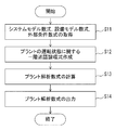
- FIG. 2 is a diagram showing an operation flow in the calculation unit 11.
- step S1 the calculation unit 11 acquires a system model equation, an equipment model equation, and an external condition equation.
- the mathematical expression group may be generated by the calculation unit 11 using the system model, the equipment model and the external condition, or may be directly input through the input unit 2.
- step S2 a first-order predicate logical expression relating to the total energy consumption is generated from the group of mathematical expressions acquired in step S1.
- step S3 the first-order logical formula generated in step S2 is processed to obtain a total energy consumption formula.
- step S4 information such as a total energy consumption formula is output to the output unit 12, and the process is ended.
- FIG. 3 is a diagram for explaining a method of generating a first-order predicate logical expression in step S2 of FIG. 2 and a method of calculating a total energy consumption formula in step S3.
- the calculation unit 11 combines the system model equation F1, the equipment model equation F2 and the external condition equation F3 with a logical product ( ⁇ ) to generate the equation (3-2) in FIG. Then, for the equation (3-2), the existence symbol ( ⁇ ) is further added to variables excluding the variable a representing the desired property of the facility and the variable P representing the total energy consumption of the plant (FIG. 3 (3-1)). Thus, a first-order predicate formula ⁇ is generated.
- ⁇ : ⁇ P1, ..., ⁇ PN ⁇ L ⁇ L 1, ..., ⁇ LN (F1 ⁇ F2 ⁇ F3)
- L is a variable that represents the total load of the plant.
- N represents the number of facilities
- Ln represents the load of the facility n.
- the calculation unit 11 applies the restrictive symbol elimination algorithm to the generated first-order predicate logical expression ⁇ to obtain a logical expression ⁇ representing the relationship satisfied by the variable a representing the property of the facility and the variable P representing the total energy consumption. And outputs this to the output unit 12.
- the output unit 12 generates a graph representing the relationship between the variable a representing the property of the facility and the variable P representing the total energy consumption of the plant from the logical expression ⁇ input from the calculation unit 11.
- the output unit 12 outputs, to the display unit 5, information such as the generated graph, that is, information obtained as a result of performing the analysis support process in the energy analysis support apparatus 1.
- the display unit 5 displays the calculation result in the energy analysis support device 1 based on the information input from the output unit 12.
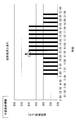
- FIG. 4 is a view schematically showing a graph generated by the output unit 12.
- one axis (horizontal axis) takes a variable a that represents the characteristics of the facility, and the other axis (vertical axis) takes a variable P that represents the total energy consumption of the plant.
- An area A satisfied by the logical expression ⁇ is visualized.
- the energy analysis support device 1 performs calculation of various mathematical expressions using the input information such as various models, and obtains a graph of a calculation result using a specific example. explain. First, information such as various models input to the energy analysis supporting apparatus 1 will be described with reference to FIGS. 5 to 7.
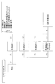
- FIG. 5 is a diagram illustrating a system model of a plant.
- the air conditioning system of FIG. 5 has a plurality of refrigerators, and the plurality of refrigerators use the electric power supplied from the power supply to supply the thermal load required by the space to be air-conditioned.
- the system model is composed of the equipment configuration of the air conditioning system shown in FIG. 5 and the heat load and power consumption of each equipment.
- the refrigerator # 1 consumes the power P1 [kW] with respect to the thermal load L1 [kW].
- the refrigerator # 2 consumes the power P2 [kW] for the heat load L2 [kW], and the refrigerator # 3 consumes the power P3 [kW] for the heat load L3 [kW].
- the refrigerator # 4 consumes the power P4 [kW] with respect to the heat load L4 [kW].
- the sum of the power consumption P1 to P4 consumed by each of the refrigerator # 1 to # 4 is the total power consumption P [kW] consumed in the entire system, and the total heat load L [kW] required by the air conditioning target space
- the thermal loads L1 to L4 [kW] of the respective refrigerator # 1 to # 4 are distributed.
- FIG. 6 is a diagram illustrating an installation model.
- the facility model of FIG. 6 is configured from the power consumption characteristics with respect to the heat load of the existing machines, ie, the refrigerators # 1 to # 3.
- Each refrigerator # 1 to # 3 has different power consumption characteristics and upper and lower limit constraints.
- FIG. 7 is a diagram illustrating an external condition.
- the total heat load L of the entire air conditioning system for responding to the request of the air conditioning target space is set to 500 [kW].
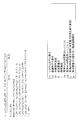
- FIG. 8 is a diagram illustrating a group of mathematical expressions generated by the calculation unit 11 from the system model, the equipment model, and the external condition of FIGS. 5 to 7.
- the system model equation F1 is an equation representing the air conditioning system model of FIG. 5, and is an equation obtained by combining two equations (8-1) and (8-2) with a logical product.
- Formula (8-1) of FIG. 8 shows that the sum total of the power consumption P1 to P4 of each refrigerator # 1 to # 4 is equal to the total power consumption P which the power supply supplies to each refrigerator # 1 to # 4.
- the equation (8-2) represents that the total heat load L of the space to be air-conditioned is distributed to the refrigerators # 1 to # 4.
- the equipment model formula F2 is a formula that expresses the equipment model of FIG. 6, and is composed of a formula that combines the formulas representing the characteristics of each of the four refrigerators # 1 to # 4 with a logical product.
- the 4th line is a numerical expression showing the characteristic of refrigerator # 4 newly introduced among the following expression F2.
- the variable a included in the equation representing the characteristic of the refrigerator # 4 represents the power consumption characteristic with respect to the load of the refrigerator # 4.
- the external condition formula F3 is a formula representing the external condition of FIG.
- the calculation unit 11 holds the system model formula F1, the equipment model formula F2 and the external condition formula F3 in storage means such as a memory (not shown) in FIG. 1, and uses these formulas to hold the following formula Perform the process.
- FIG. 9 is a diagram for explaining a method of generating a first-order predicate logical expression ⁇ from the mathematical expression groups F1 to F3 of FIG.
- the calculation unit 11 of the energy analysis support device 1 combines the equation group of FIG. 8, that is, the system model equation F1, the equipment model equation F2, and the external condition equation F3 with a logical product to represent the entire system (F1). Generate ⁇ F2 ⁇ F3) (equation (9-2) in FIG. 9).
- the calculation unit 11 presents the existence symbol ( ⁇ ) as a variable excluding the variable P representing the total energy consumption and the variable a representing the characteristic of the refrigerator # 4 with respect to the formula F1 ⁇ F2 ⁇ F3 representing the entire system. Is generated ((9-1) in FIG. 9) to generate a first-order predicate formula ⁇ regarding the total power consumption.
- the calculation unit 11 applies the quantifier elimination algorithm (QE []) to the first-order predicate logical formula ⁇ in FIG.
- the logical expression ⁇ is obtained by eliminating the variables.
- the logical expression ⁇ is a relational expression that the variable a representing the characteristic of the refrigerator # 4 and the variable P representing the total power consumption of the air conditioning system satisfy.
- the logical expression ⁇ represents the range of the total power consumption P that can be performed by changing the load distribution of each of the refrigerator # 1 to # 4 with respect to the power consumption characteristic a of the refrigerator # 4.
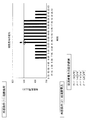
- FIG. 11 is a diagram illustrating a graph displayed on the display unit 5.
- the calculation unit 11 of the energy analysis support device 1 eliminates the limitation symbol from the first-order predicate logical expression ⁇ to obtain the logical expression ⁇ in FIG.
- the obtained logical expression ⁇ is passed to the output unit 12 of the energy analysis support device 1.
- the output unit 12 takes the variable P representing the total power consumption on the vertical axis and the variable a representing the power consumption characteristic of the refrigerator # 4 on the horizontal axis from the logical formula ⁇ , and represents the area A1 satisfied by the logical formula ⁇ Generate a graph. In FIG. 11, the area A1 is indicated by hatching.
- the output unit 12 outputs the generated image information of the graph to the display unit 5.
- the display unit 5 displays the graph of FIG. 11 based on the information input from the output unit 12.
- the lower limit value in the vertical axis direction of the region A1 is the optimal power consumption with respect to the value of the power consumption characteristic a of the refrigerator # 4.
- the lower limit LM_lw corresponds to the optimum total power consumption with respect to the value of the power consumption characteristic a of the refrigerator # 4.
- the user refers to the lower limit LM_lw of the graph in FIG. 11 and grasps the total power consumption P of the whole air conditioning system in the case of the operation for realizing the most power saving, and the power consumption characteristic a of the refrigerator # 4 to be introduced Can be determined. Therefore, the user can appropriately determine the characteristic (power consumption characteristic in the example) of the newly introduced facility (refrigerator # 4) with reference to the graph, whereby the newly introduced facility can be appropriately determined. It is possible to make a decision.
- the first-order predicate logical expression is generated from the input system model, the facility model, and the external condition. Then, a punctuation elimination algorithm is applied to the generated first-order predicate logical expression to obtain a logical expression representing the relationship between the characteristics of a certain facility of the plant and the total power consumption of the plant.
- the first-order predicate formula is a formula that expresses the whole of the plant generated from the input system model etc., variables other than the variables that you want to finally obtain as the processing result, ie, the characteristics of a certain facility and total power consumption. It is generated by giving the presence symbol ( ⁇ ) to a variable.
- the area where the characteristics of the equipment and the total energy consumption satisfy includes both the area when the equipment to be introduced is operated and the case where the equipment is not operated. .
- this modification it differs in the point which draws the graph which distinguished the case of the case of operating a certain installation, and the case of not making it operate.
- FIGS. 1 and 5 to 7 As described with reference to.
- the energy analysis supporting device 1 When the information shown in FIG. 5 to FIG. 7 is input, the energy analysis supporting device 1 first generates a system model equation, an equipment model equation, and an external condition equation, as in the above embodiment.
- the system model equation F1 and the external condition equation F3 are the same as in the previous embodiment, and are as described with reference to FIG.
- FIG. 12 is a diagram illustrating an equipment model equation generated in the present modification.
- the calculation unit 11 of the energy analysis support apparatus 1 uses, as an equipment model equation, equations F2 ′ and F2 when the refrigerator # 4 to be newly introduced to the air conditioning system is not operated and when it is operated.
- the equipment model formula F2 ′ ′ is expressed by the formula of the equipment model formula F2 in FIG. 8 excluding the following formula (12-1) representing the condition that the refrigerator # 4 is not operated.
- the calculation unit 11 generates two first-order predicate logical expressions using each of the generated two equipment model expressions F2 ′ and F2 ′ ′.
- FIG. 13 is a diagram showing first-order predicate logical expressions' 2 'and' 2 'generated using the expressions F1 and F3 of FIG. 8 and the expressions F2' and F2 '' of FIG.
- FIG. 14 is a diagram showing logical expressions ⁇ 2 ′ and ⁇ 2 ′ ′ obtained by applying the restrictive symbol elimination algorithm to the first-order predicate logical expressions ⁇ 2 ′ and ⁇ 2 ′ ′.
- the logical formulas ⁇ 2 ′ and ⁇ 2 ′ ′ represent the relationship between the power consumption characteristic a of the refrigerator # 4 and the total power consumption P when the refrigerator # 4 newly introduced to the air conditioning system is not operated and operated, respectively.
- the output unit 12 receives the equations (14-1) and (14-2) from the calculation unit 11, the output unit 12 generates a graph capable of comparing the regions satisfied by the two equations based thereon. Then, the output unit 12 outputs this to the display unit 5 as information obtained as a result of performing the analysis support process in the energy analysis support device 1.
- the display unit 5 displays a graph based on the input information.
- FIG. 15 is a diagram illustrating a graph displayed on the display unit 5. As in the graph of FIG. 11, the vertical axis represents a variable P representing the total power consumption, and the horizontal axis represents a variable a representing the power consumption characteristic of the refrigerator # 4.
- the user performs analysis by comparing the respective regions when the newly introduced refrigerator # 4 is not in operation and in operation, with reference to the graph illustrated in FIG. 15.
- the refrigerator # 4 when the value of the power consumption characteristic a of the refrigerator # 4 is small, the refrigerator # 4 is operated and the other inefficient refrigerators are stopped to stop the operation, that is, the refrigerator # 1. It can be seen that the total power consumption P can be significantly suppressed as compared with the case of operating # 3 (* 1 in FIG. 15).
- the total power consumption P can be reduced by not operating the refrigerator # 4, that is, even if a new refrigerator # 4 is introduced, the total consumption It can be seen that the power P can not be suppressed (* 2 in FIG. 15).
- Modification 2 In said embodiment and modification 1, the case where the air conditioning object space is relatively high heat load is set as an external condition. On the other hand, in this modification, the case where the air conditioning target space has a relatively low thermal load is set, and a logical expression ⁇ representing the relationship between the characteristics of the facility to be introduced at the low thermal load and the total energy consumption is determined. Draw on a graph.
- the energy analysis supporting device 1 When the information shown in FIGS. 5 to 7 is input, the energy analysis supporting device 1 generates a system model equation, an equipment model equation, and an external condition equation, as in the above embodiment and the first modification.
- facility model formulas F2 ′ and F2 ′ ′ are generated for each of the case where the newly introduced refrigerator # 4 is operated and the case where it is not operated, and the respective refrigerator # 4 is generated.
- the case of obtaining the relational expression between the power consumption characteristic a and the total power consumption P will be described.
- the system model formula F1 is the same as that of the above embodiment and is as described with reference to FIG.
- the equipment model formulas F2 ′ and F2 ′ ′ are as described in the first modification with reference to FIG.
- FIG. 16 is a diagram for explaining an external conditional expression generated in the present modification.
- the thermal load L in the graph of the total thermal load of the air-conditioned space according to the time zone on the upper side of FIG. 16 is a time zone such as "6 o'clock to 7 o'clock" Set 400 [kW] which is the value of relatively low total heat load set in.
- the calculation unit 11 generates two first-order predicate logical expressions using the system model expression F1, the two equipment model expressions F2 'and F2' ', and the external condition expression F3' at low heat load.
- FIG. 17 is a diagram showing two generated first order predicate formulas '3' and '3'.
- Two first-order predicate logic formulas ⁇ 3 'and ⁇ 3''in FIG. 17 are first-order predicate formulas relating to the total power consumption when the refrigerator # 4 is not operated and when it is operated.
- the calculation unit 11 is an equation (F1 ⁇ F2′ ⁇ F3 ′) representing the entire system from the system model equation F1 of FIG. 8, the equipment model equation F2 ′ and F2 ′ ′ of FIG. 12, and the external condition equation F3 ′ of FIG. ), (F1 ⁇ F2′′ ⁇ F3 ′).
- the variable to which the presence symbol ( ⁇ ) is assigned is the same as in the above-described embodiment and the first modification.
- FIG. 18 is a diagram showing logical expressions ⁇ 3 ′ and ⁇ 3 ′ ′ obtained by applying the restrictive symbol elimination algorithm to the first-order predicate logical expressions ⁇ 3 ′ and ⁇ 3 ′ ′.
- the logical expressions ⁇ 3 ′ and ⁇ 3 ′ ′ are relational expressions that the power consumption characteristic a of the refrigerator # 4 and the total power consumption P satisfy when the refrigerator # 4 is not operated and when the refrigerator # 4 is operated at low heat load, respectively.
- the output unit 12 receives the logical expressions ⁇ 3 ′ and ⁇ 3 ′ ′ from the calculation unit 11, the output unit 12 generates a graph capable of comparing the regions satisfied by the two expressions based thereon, and outputs the graph to the display unit 5.
- FIG. 19 is a diagram illustrating a graph displayed on the display unit 5. As in the graphs of FIGS. 11 and 15, the vertical axis represents the total power consumption P, and the horizontal axis represents the power consumption characteristic a of the refrigerator # 4.
- a graph is created in which areas A3 'filled with the two logical expressions ⁇ 3' and ⁇ 3 '' are hatched to make it possible to distinguish A3 '' by oblique lines.
- the user performs analysis by comparing the respective regions when the refrigerator # 4 to be newly introduced at low heat load is not operated and when it is operated.
- the refrigerator # 4 is operated when the range of the power consumption characteristic a of the refrigerator # 4 is from 0.10 to 035 (the whole area of the graph shown in FIG. 15). It is understood that the total power consumption P can be suppressed if the user is allowed to do so.
- FIG. 19 the relationship between the power consumption characteristic a of the refrigerator # 4 and the total power consumption P at the time of low heat load is illustrated as a graph which can be identified when the refrigerator # 4 is not operated and when it is operated. doing.
- various modified examples can be considered such as a graph comparing high heat load time and low heat load time by using logical expressions ⁇ 2 ′ and ⁇ 2 ′ ′ of FIG. 14 obtained in the first modification, for example.
- Modification 3 In the above embodiment and Modifications 1 and 2, the relationship between the variable a representing the power consumption characteristic which is one of the characteristics of the equipment (refrigerator) and the total power consumption P is obtained. On the other hand, in this modification, the relationship between the variable representing the characteristic other than the power consumption characteristic of the newly introduced refrigerator and the total power consumption P is determined.
- the configuration of the energy analysis support device 1 and the information to be input are the same as those of the above-described embodiment and the like, and are as described with reference to FIG. 1 and FIG. 5 to FIG.
- the energy analysis supporting device 1 When the information shown in FIGS. 5 to 7 is input, the energy analysis supporting device 1 generates a system model equation, an equipment model equation, and an external condition equation, as in the above embodiment and the like.
- the system model equation F1 and the external condition equation F3 are as described above with reference to FIG.
- FIG. 20 is a diagram for explaining an equipment model formula generated in the present modification.
- a facility model formula F2 ′ ′ ′ in the case of operating the refrigerator # 4 is generated using a variable b that represents the upper limit of the heat load of the refrigerator # 4.
- the power consumption characteristic of the refrigerator # 4 is fixed to 0.16.
- a formula representing the characteristic of the refrigerator # 4 is as follows.
- the calculation unit 11 generates a first-order predicate logical expression using the system model expression F1, the facility model expression F2 ′ ′ ′, and the external condition expression F3.
- FIG. 21 is a diagram showing the generated first-order predicate logical expression '4'.
- the first-order predicate logical expression ⁇ 4 ′ ′ in FIG. 21 is a first-order predicate logical expression in which the upper limit b of the heat load of the refrigerator # 4 is a variable.
- the calculation unit 11 generates an equation (F1 ⁇ F2 ′ ′ ′ ⁇ F3) representing the entire system from the system model equation F1 of FIG. 8 and the facility model F2 ′ ′ ′ of FIG. 20 and the external condition equation of FIG.
- the existence symbol ( ⁇ ) is added to variables other than the variables b and P to generate a logical expression ⁇ 4 ′ ′.
- FIG. 22 is a diagram showing a logical expression ⁇ 4 ′ ′ obtained by applying the restrictive symbol elimination algorithm to the first-order predicate logical expression ⁇ 4 ′ ′.
- the logical formula ⁇ 4 ′ ′ represents the relationship between the upper limit b of the heat load L4 of the refrigerator # 4 and the total power consumption P.
- the output unit 12 receives the logical expression ⁇ 4 ′ ′ from the calculation unit 11, the output unit 12 generates a graph representing an area that the logical expression ⁇ 4 ′ ′ satisfies based on the logical expression ⁇ 4 ′ ′ and outputs the graph to the display unit 5.
- FIG. 23 is a diagram illustrating a graph displayed on the display unit 5.
- the vertical axis represents the total power consumption P, as in the graphs of FIGS.
- the upper limit b of the heat load L4 of the refrigerator # 4 is taken.
- the area A4 '' represents the area that the variables b and P of the logical expression [phi] 4 '' satisfy, by hatching.
- the region A4 ′ ′ is the upper limit b of the thermal load L4 of the refrigerator # 4 and the total power consumption P when operating the refrigerator # 4. Is an area that the
- an area A4 'in FIG. 23 is an area where the upper limit b of the heat load L4 of the refrigerator # 4 and the total power consumption P when the refrigerator # 4 is not operated.
- Region A 4 ′ utilizes the logical expression ⁇ 2 ′ determined for the case where the refrigerator # 4 is not operated in the second modification.
- the logical expression ⁇ 2 ′ is obtained by eliminating the limitation from the first-order predicate logical expression ⁇ 2 ′, and the first-order predicate logical expression ⁇ 2 ′ uses the system model expression F1, the facility model expression F2 ′ and the external condition expression F3. Is generated.
- the equipment model formula F2 'does not depend on the upper limit b of the heat load L4 of the refrigerator # 4. Therefore, the logical expression ⁇ 2 ′ determined using the equipment model F2 ′ is also not based on the variable b. Therefore, the logical expression ⁇ 2 ′ is the upper limit b of the heat load L4 of the refrigerator # 4 of the present modification and the total b It can be said that the relationship with the power consumption P is expressed.
- the user refers to the graph illustrated in FIG. 23 to compare and analyze the respective regions when the refrigerator # 4 is operated and not operated.
- the energy analysis support device 1 eliminates the limitation sign from the generated first-order predicate logical expression, obtains a logical expression representing the relationship between the property of the facility and the total consumption energy, and obtains the graph from this. It is generated.
- the logical expression obtained as a result of eliminating the limitation symbol differs in that it represents a relationship which is satisfied between the characteristics of the equipment.
- the energy analysis supporting device 1 will be described focusing on differences from the first embodiment.
- the configuration diagram of the energy analysis support device 1 according to the present embodiment is the same as that according to the first embodiment of FIG. 1.
- the energy analysis support device 1 includes a calculation unit 11 and an output unit 12, and is connected to the input unit 2 such as the keyboard 2A and the pointing device 2B and the display unit 5 such as a monitor.
- the energy analysis support device 1 receives inputs of a system model, an equipment model, and an external condition via the input unit 2 as in the first embodiment.
- the information to be input is also the same as that of the above embodiment, and is as described with reference to FIGS. 5 to 7 and the like.
- the energy analysis support device 1 generates a mathematical expression such as a system model mathematical expression from the input information to generate a first-order predicate logical expression, and erases a limiting symbol from the generated first-order predicate logical expression. And get the logical formula.
- the logical expressions obtained by eliminating the limitation symbols in the present embodiment represent the relationships that the variables representing the characteristics of the plant equipment satisfy.
- the energy analysis support device 1 generates a graph based on the obtained logical expression, outputs the graph to the display unit 5, and displays the graph.
- FIG. 24 is a diagram showing an operation flow in the calculation unit 11.
- Step S11 is the same as step S1 of FIG. 2 in comparison with the operation flow of the first embodiment of FIG.
- step S12 the calculation unit 11 generates a first-order predicate logical expression relating to the operating state of the plant.
- “the first-order predicate logical expression relating to the operating state of the plant” is different from the “first-order predicate logical expression relating to the total consumption energy” generated in step S2 of FIG. .
- steps S13 and S14 processing similar to that of steps S3 and S4 in FIG. 2 is performed. That is, a logical expression in which the limiting symbol has been eliminated is calculated from the first-order predicate logical expression generated in step S12, the plant analysis mathematical expression obtained by the calculation is output to the output unit 12, and the processing is ended.
- FIG. 25 is a diagram for explaining a first-order predicate logical expression generated by the calculation unit 11 in the present embodiment and a logical expression obtained by deleting a limitation symbol from the first-order predicate logical expression.
- Calculation unit 11 like the first embodiment described above, the system model equation F1, the equipment model F2 and external conditions formula F3 i binds with logical ( ⁇ ) (equation 25 (25-2)) . Then, in the present embodiment, the calculation unit 11 assigns an existing symbol ( ⁇ ) to variables other than the two variables a and b representing the characteristic of the facility ((25-1) in FIG. 25). Generate a rank predicate formula ⁇ i .
- the first-order predicate logical expression ⁇ ⁇ i generated in the present embodiment is referred to as “first-order predicate logic relating to the operating state of the plant” below. It is also called a formula.
- the calculation unit 11 applies the limited symbol elimination algorithm to each of the first-order predicate logical expressions ⁇ i relating to the operating states of I plants, and represents a logical expression i i representing the relationship satisfied by the variables a and b representing the characteristics of the equipment. And output this to the output unit 12.
- Generate The output unit 12 outputs this to the display unit 5 as information obtained as a result of performing the analysis support processing in the energy analysis support device 1.
- the display unit 5 displays the calculation result in the energy analysis support device 1 based on the information input from the output unit 12.
- FIG. 26 is a view schematically showing a graph generated by the output unit 12.
- one axis (horizontal axis) takes a variable a representing the property of the facility
- the other axis (vertical axis) takes another variable b representing the property of the facility.
- the region satisfied by the logical expression ⁇ i obtained for each of the operating conditions of the plant, that is, each of the plurality of external condition expressions F3 i is visualized by color coding or the like.
- the system model and the facility model of the plant are the same as in the first embodiment, as shown in FIGS. 5 and 6.
- FIG. 27 is a diagram illustrating an external condition.
- the first external condition is the total heat load L of the entire air conditioning system.
- the total heat load L is set to 500 [kW].
- the second external condition is the total power consumption P of the entire air conditioning system.
- four conditions are set as the second external condition, and 150 kW or less, 140 kW or less, 130 kW or less, and 120 kW or less are set.
- FIG. 28 is a diagram illustrating a group of mathematical expressions generated by the calculation unit 11 from the system model of FIG. 5, the equipment model of FIG. 6, and the external conditions of FIG.
- the power consumption characteristic of the equipment model formula F2 is represented by “variable a” as in the first embodiment.
- the upper limit of the heat load L4 of the refrigerator # 4 is represented by "variable b”.
- FIG. 29 is a diagram for explaining a method of generating a first-order logic formulas [psi i from equation group F1, F2, F3 i in FIG 28.
- calculation unit 11 the generated equation F1, F2, F3 i of FIG. 28 coupled with logical AND ( ⁇ ), the variable a, existential quantifiers on variables other than b ( ⁇ ) to generate a first-order predicate formula ⁇ i .
- the external condition of i 1, specifically, the total heat load L of the air conditioning system is 500 kW, and the total power consumption P of the air conditioning system is 150 kW First-order predicate formula ⁇ 1 in the case where the following condition is an external condition is exemplified.
- Calculation unit 11 outputs the generated first order predicate each quantifier elimination algorithm formulas ⁇ 1 ⁇ ⁇ 4 was (QE []) by applying the logical expression was erased granted variables existential quantifier phi 1 ⁇ phi Get four .
- the logical expressions ⁇ 1 to ⁇ 4 are relational expressions that the power consumption characteristic a of the refrigerator # 4 and the upper limit b of the heat load L4 satisfy.
- FIG. 31 is a view showing an example of a screen displayed on the display unit 5, and the regions A1 to A4 satisfied by the logical expressions ⁇ 1 to ⁇ 4 are shown by graphs.
- the ordinate represents the upper limit b of the heat load L4 of the refrigerator # 4, and the abscissa represents the power consumption characteristic a of the refrigerator # 4.
- Areas A1 to A4 in FIG. 31 represent the installed capacity of the refrigerator # 4 required to reduce the total power consumption P of the air conditioning system to 150, 140, 130, and 120 [kW] or less.
- the ranges of the regions A1 to A4 satisfied by the power consumption characteristic a of the refrigerator # 4 and the upper limit b of the heat load L4 differ depending on the external conditions.
- the user changes the total power consumption P according to the correlated characteristics such as the power consumption characteristic a of the refrigerator # 4 and the upper limit b of the heat load L4. Can be considered.
- the regions A1 to A4 may be arranged side by side on the screen as illustrated in FIG. 31, or one graph may display visibly a portion of each region overlapping.
- FIG. 32 is a view showing another example of the screen displayed on the display unit 5, and the areas A1 to A4 satisfied by the logical expressions ⁇ 1 to ⁇ 4 are displayed distinguishably by color coding or the like.
- the areas A1 to A4 are displayed so as to be distinguishable by the user by hatching or hatching.
- the user attempts to suppress the total power consumption P to a predetermined value or less, for example, when the power consumption characteristic a of the newly introduced refrigerator # 4 is 0.11.
- the optimum value of the power consumption characteristic a of the refrigerator # 4 is determined when trying to suppress the total power consumption to a predetermined value or less. can do. It can be seen that the power consumption characteristic a should be 0.27 or less in order to reduce the total power consumption to 150 kW or less under the condition that the upper limit of the heat load is 200 kW or more. Similarly, it is understood that the power consumption characteristic a should be set to 0.18 or less in order to set the total power consumption to 140 [kW] or less under the same conditions.
- a formula representing the relationship between the characteristics of a plurality of correlated facilities is obtained, and how the total power consumption of the plant changes. Can be visualized. For the user, using the visualized result, for example, it becomes easy to study how much the energy saving effect can be expected if equipment with which efficiency and constraints are introduced.
- the constraint condition (upper limit of heat load in the above example) of the equipment to be newly introduced is set to one variable b, and a logical expression ⁇ i including this is obtained and provided to the user for analysis. doing.
- energy saving may be realized when, for example, the constraint condition is alleviated (in the above example, the upper limit of the heat load is increased), such a state Can also be verified.
- the energy analysis support device 1 of FIG. 1 can be configured, for example, using an information processing device (computer) as shown in FIG.
- the information processing apparatus shown in FIG. 33 includes a CPU (central processing unit) 1001, a memory 1002, an input unit 1003, an output unit 1004, an external storage unit 1005, a medium drive unit 1006, and a network connection unit 1007. It is connected.
- the memory 1002 includes, for example, a read only memory (ROM), a random access memory (RAM), and the like, and stores programs and data used for processing.
- the CPU 1001 performs necessary processing by executing a program using the memory 1002.
- the calculation unit 11 and the output unit 12 in FIG. 1 correspond to functions implemented by executing a program stored in the memory 1002.
- the input device 1003 is, for example, a keyboard, a pointing device, a touch panel, etc., and is used to input an instruction or information from an operator such as a network administrator.
- the output device 1004 is, for example, a display, a printer, a speaker, and the like, and is used to output an inquiry to a user, an alarm, a processing result, and the like.
- the external storage device 1005 is, for example, a magnetic disk device, an optical disk device, a magneto-optical disk device, a tape device or the like.
- the information processing apparatus stores the program and data in the external storage device 1005, loads them into the memory 1002 and uses them as needed.
- the medium drive device 1006 drives a portable recording medium 1009 and accesses the recorded contents.
- the portable recording medium 1009 is an arbitrary computer-readable recording medium such as a memory card, a flexible disk, a compact disk read only memory (CD-ROM), an optical disk, a magneto-optical disk and the like.
- the operator stores the program and data in the portable storage medium 1009 and loads them into the memory 1002 for use as needed.
- the network connection device 1007 is connected to an arbitrary communication network such as a local area network (LAN) or the Internet, and performs data conversion involved in communication.
- the information processing apparatus receives the program and data from an external apparatus via the network connection apparatus 1007, loads them into the memory 1002, and uses them as necessary.
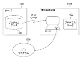
- FIG. 34 shows a computer readable recording medium capable of supplying a program and data to the information processing apparatus of FIG.
- Programs and data stored in the portable storage medium 1009 or the database 1103 of the server 1101 are loaded into the memory 1002 of the information processing apparatus 1102.
- the server 1101 generates a carrier signal that carries the program and data, and transmits the carrier signal to the information processing apparatus 1102 via any transmission medium on the network.
- the CPU 1001 executes the program using the data and performs necessary processing.
Landscapes
- Physics & Mathematics (AREA)
- General Physics & Mathematics (AREA)
- Engineering & Computer Science (AREA)
- Automation & Control Theory (AREA)
- Feedback Control In General (AREA)
- Management, Administration, Business Operations System, And Electronic Commerce (AREA)
Abstract
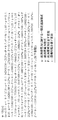
プラントを構成する設備の特性を最適化する際に、何度も計算を繰り返すことを不要としつつ、どのように設備の特性を設定すべきか等の情報をユーザに提示することのできる技術を提供する。複数の設備からなるプラントのエネルギー解析支援装置1において、計算部11は、プラントのモデルと、プラントを構成する設備の能力を表す設備モデルと、プラントの消費エネルギーまたは負荷を表す外部条件とが与えられると、プラントのモデルを表す数式、設備モデルを表す数式及び外部条件を表す数式より、解析対象の設備の特性を表した少なくとも一の変数を含む論理式を生成する。出力部12は計算部11により生成された論理式に基づいて、一の変数が表す解析対象の設備の特性を2軸のうちの一の軸とするグラフを生成して出力する。
Description
本発明は、電力、ガス等の資源を供給する資源供給設備と資源を需要してエネルギーを消費する資源需要設備とを有するプラントの解析を支援する技術に関する。
複数の設備を備え、設備の運転時にはエネルギーを消費するプラントの運転を制御する際には、消費電力等の消費エネルギーを最小化するように作成された運転スケジュールに基づいて、設備ごとの負荷配分が決定されている。これに関して、例えば、特許文献1では、外気温度や日射量、在室人数予測等の外部条件から建物の熱負荷を予測して、プラント全体における総消費電力が最小となる運転スケジュールを立案するシステム制御装置が開示されている。
また、特許文献2では、システムの装置構成を変更しながら消費エネルギー等を最適にする運用方法を計算することで、構成変更時の意思決定を支援する方法が提案されている。
一方、システム制御等の問題を一階述語論理式で表現し、これを解くことで、システムの最適化を行う技術が知られている(例えば、非特許文献1を参照)。具体的には、多項式の等式や不等式を論理積(∧)や論理和(∨)等の結合記号で結合した論理式に対して、一部の変数に限定記号と総称される全称記号(∀)や存在記号(∃)を付与してなる一階述語論理式を生成する。そして、この一階述語論理式における限定記号の付与された変数(束縛変数)を消去して、それ以外の変数(自由変数)が満たすべき論理式を導くことで、システムの最適化を行う。
例えば、特許文献3では、制御系を一階述語論理式に変換し、一階述語論理式における限定記号の付いた変数を消去し、得られた式から制御系を解析する制御系解析・設計装置について開示されている。
穴井宏和・横山和弘著、「QEの計算アルゴリズムとその応用 数式処理による最適化」、東京大学出版会、2011年、p.214-221
上記の一階述語論理式を解くことによりシステムを最適化する技術を含め、従来の技術では、プラントを構成する複数の設備のうちの特定の設備を使用した場合における最適な消費エネルギーについてしか計算することができなかった。すなわち、従来技術では、エネルギー効率等の所定の設備の特性を変化させた場合に、これに応じて最適な消費エネルギーがどのように変化するかを直接求めることができなかった。
このように、従来は、設備のエネルギー効率や制約条件等の特性を変更することによってどれだけ省エネが実現できるかを把握するためには、様々な設備の特性の値を具体的に設定してそれぞれについて最適化の計算を実施して、計算結果同士を比較していく必要があり、試行錯誤によるしか手段がなかった。
本発明は、プラントを構成する設備の特性を最適化する際に、何度も計算を繰り返すことを不要としつつ、どのように設備の特性を設定すべきか等の情報をユーザに提示することのできる技術を提供することを目的とする。
本発明の一態様に係るエネルギー解析支援装置は、複数の設備からなるプラントのエネルギー解析支援装置であって、下記の構成を有する。
・前記プラントのモデルと、前記プラントを構成する設備の能力を表す設備モデルと、前記プラントの消費エネルギーまたは負荷を表す外部条件とが与えられると、前記プラントのモデルを表す数式、前記設備モデルを表す数式及び外部条件を表す数式より、解析対象の設備の特性を表した少なくとも一の変数を含む論理式を生成する計算部;及び
・前記計算部により生成された論理式に基づいて、前記一の変数が表す前記解析対象の設備の特性を2軸のうちの一の軸とするグラフを生成して出力する出力部。
・前記プラントのモデルと、前記プラントを構成する設備の能力を表す設備モデルと、前記プラントの消費エネルギーまたは負荷を表す外部条件とが与えられると、前記プラントのモデルを表す数式、前記設備モデルを表す数式及び外部条件を表す数式より、解析対象の設備の特性を表した少なくとも一の変数を含む論理式を生成する計算部;及び
・前記計算部により生成された論理式に基づいて、前記一の変数が表す前記解析対象の設備の特性を2軸のうちの一の軸とするグラフを生成して出力する出力部。
また、本発明の一態様に係るエネルギー解析支援プログラムは、複数の設備からなるプラントのエネルギー解析支援処理を情報処理装置に実行させるためのエネルギー解析支援プログラムであって、下記の構成を有する。
・前記プラントのモデルと、前記プラントを構成する設備の能力を表す設備モデルと、前記プラントの消費エネルギーまたは負荷を表す外部条件とが与えられると、前記プラントのモデルを表す数式、前記設備モデルを表す数式及び外部条件を表す数式より、解析対象の設備の特性を表した少なくとも一の変数を含む論理式を生成するステップ;及び
・前記生成された論理式に基づいて、前記一の変数が表す前記解析対象の設備の特性を2軸のうちの一の軸とするグラフを生成して出力するステップ。
・前記プラントのモデルと、前記プラントを構成する設備の能力を表す設備モデルと、前記プラントの消費エネルギーまたは負荷を表す外部条件とが与えられると、前記プラントのモデルを表す数式、前記設備モデルを表す数式及び外部条件を表す数式より、解析対象の設備の特性を表した少なくとも一の変数を含む論理式を生成するステップ;及び
・前記生成された論理式に基づいて、前記一の変数が表す前記解析対象の設備の特性を2軸のうちの一の軸とするグラフを生成して出力するステップ。
また、本発明の一態様に係る記録媒体は、複数の設備からなるプラントのエネルギー解析支援処理を情報処理装置に実行させるためのエネルギー解析支援プログラムを記録した記録媒体であって、下記の構成を有する。
・前記プラントのモデルと、前記プラントを構成する設備の能力を表す設備モデルと、前記プラントの消費エネルギーまたは負荷を表す外部条件とが与えられると、前記プラントのモデルを表す数式、前記設備モデルを表す数式及び外部条件を表す数式より、解析対象の設備の特性を表した少なくとも一の変数を含む論理式を生成するステップ;及び
・前記生成された論理式に基づいて、前記一の変数が表す前記解析対象の設備の特性を2軸のうちの一の軸とするグラフを生成して出力するステップ。
・前記プラントのモデルと、前記プラントを構成する設備の能力を表す設備モデルと、前記プラントの消費エネルギーまたは負荷を表す外部条件とが与えられると、前記プラントのモデルを表す数式、前記設備モデルを表す数式及び外部条件を表す数式より、解析対象の設備の特性を表した少なくとも一の変数を含む論理式を生成するステップ;及び
・前記生成された論理式に基づいて、前記一の変数が表す前記解析対象の設備の特性を2軸のうちの一の軸とするグラフを生成して出力するステップ。
また、本発明の一態様に係るエネルギー解析支援方法は、複数の設備からなるプラントのエネルギー解析支援方法であって、下記の構成を有する。
・前記プラントのモデルと、前記プラントを構成する設備の能力を表す設備モデルと、前記プラントの消費エネルギーまたは負荷を表す外部条件とが与えられると、前記プラントのモデルを表す数式、前記設備モデルを表す数式及び外部条件を表す数式より、解析対象の設備の特性を表した少なくとも一の変数を含む論理式を生成するステップ;及び
・前記生成された論理式に基づいて、前記一の変数が表す前記解析対象の設備の特性を2軸のうちの一の軸とするグラフを生成して出力するステップ。
・前記プラントのモデルと、前記プラントを構成する設備の能力を表す設備モデルと、前記プラントの消費エネルギーまたは負荷を表す外部条件とが与えられると、前記プラントのモデルを表す数式、前記設備モデルを表す数式及び外部条件を表す数式より、解析対象の設備の特性を表した少なくとも一の変数を含む論理式を生成するステップ;及び
・前記生成された論理式に基づいて、前記一の変数が表す前記解析対象の設備の特性を2軸のうちの一の軸とするグラフを生成して出力するステップ。
本発明によれば、プラントを構成する設備の特性を最適化する際に、何度も計算を繰り返すことを不要としつつ、どのように設備の特性を設定すべきか等の情報をユーザに提示することが可能となる。
以下、本発明の実施の形態について、図面を参照して詳細に説明する。
<第1の実施形態>
図1は、本実施形態に係るエネルギー解析支援装置の構成図である。図1のエネルギー解析支援装置1は、計算部11と、出力部12とを有し、キーボード2Aやポインティングデバイス2B等の入力部2やモニタ等の表示部5と接続される。
<第1の実施形態>
図1は、本実施形態に係るエネルギー解析支援装置の構成図である。図1のエネルギー解析支援装置1は、計算部11と、出力部12とを有し、キーボード2Aやポインティングデバイス2B等の入力部2やモニタ等の表示部5と接続される。
エネルギー解析支援装置1は、入力部2(2Aや2B)を介して、プラントのシステムモデル、設備モデル及び外部条件の入力を受け付ける。エネルギー解析支援装置1の計算部11は、入力されたこれらの情報より、システムモデル数式、設備モデル数式及び外部条件数式を生成し、生成した数式を用いて一階述語論理式を生成する。計算部11は、一階述語論理式に対し限定記号消去アルゴリズムを適用して、所望の変数と総消費エネルギーとの関係を表した論理式を得る。出力部12は、計算部11が計算により得た論理式に基づきグラフを生成してこれを表示部5に出力する。表示部5は、出力部5から入力された情報に基づき、グラフを表示する。
こうして、エネルギー解析支援装置1は、解析対象の設備のエネルギー効率やプラント運転時の制約条件等の特性を変更した場合に、プラントの総消費エネルギーがどのように変化するかをユーザが解析する際にこれを支援するための情報を提供する。
なお、エネルギー解析支援装置1は、入力部2を介してシステムモデル等の情報が入力されたことを契機として、入力された情報を用いて処理を開始することもある。あるいは、既に装置内に記憶されている情報を用いて、ユーザからの開始の指示にしたがって処理を開始することもある。
図2は、計算部11における動作フローを示す図である。
計算部11は、まず、ステップS1で、システムモデル数式、設備モデル数式及び外部条件数式を取得する。これらの数式群は、システムモデル、設備モデル及び外部条件を用いて計算部11が生成してもよいし、入力部2を介して直接入力されてもよい。
ステップS2では、ステップS1で取得した数式群より、総消費エネルギーに関する一階述語論理式を生成する。
ステップS3では、ステップS2で生成した一階述語論理式を処理して総消費エネルギー数式を得る。最後に、ステップS4で、総消費エネルギー数式等の情報を出力部12に出力し、処理を終了する。
図3は、図2のステップS2の一階述語論理式を生成する方法及びステップS3の総消費エネルギー数式を計算する方法を説明する図である。
計算部11は、システムモデル数式F1、設備モデル数式F2及び外部条件数式F3を論理積(∧)で結合し、図3の数式(3-2)を生成する。そして、数式(3-2)に対し、更に、所望の設備の特性を表す変数a及びプラントの総消費エネルギーを表す変数Pを除く変数に対して存在記号(∃)を付与する(図3の(3-1))。こうして、一階述語論理式ψを生成する。
ψ:=∃P1,...,∃PN∃L∃L1,..., ∃LN(F1∧F2∧F3)
Lは、プラントの総負荷を表す変数である。また、Nは、設備の台数を表し、Pnは、設備n(n=1,2,…,N)の消費エネルギーを、Lnは、設備nの負荷を表す変数である。
ψ:=∃P1,...,∃PN∃L∃L1,..., ∃LN(F1∧F2∧F3)
Lは、プラントの総負荷を表す変数である。また、Nは、設備の台数を表し、Pnは、設備n(n=1,2,…,N)の消費エネルギーを、Lnは、設備nの負荷を表す変数である。
計算部11は、生成した一階述語論理式ψに限定記号消去アルゴリズムを適用して、設備の特性を表す変数aと総消費エネルギーを表す変数Pとが満たす関係を表した論理式φを得て、これを出力部12に出力する。
φ:=QE[ψ]
(φ:=(Pとaに関する数式))
出力部12は、計算部11から入力された論理式φより、設備の特性を表す変数aとプラントの総消費エネルギーを表す変数Pとの関係を表すグラフを生成する。そして、出力部12は、生成したグラフ等の情報すなわちエネルギー解析支援装置1において解析支援処理を行った結果得られた情報を表示部5に出力する。表示部5は、出力部12から入力された情報に基づき、エネルギー解析支援装置1における計算結果を表示する。
φ:=QE[ψ]
(φ:=(Pとaに関する数式))
出力部12は、計算部11から入力された論理式φより、設備の特性を表す変数aとプラントの総消費エネルギーを表す変数Pとの関係を表すグラフを生成する。そして、出力部12は、生成したグラフ等の情報すなわちエネルギー解析支援装置1において解析支援処理を行った結果得られた情報を表示部5に出力する。表示部5は、出力部12から入力された情報に基づき、エネルギー解析支援装置1における計算結果を表示する。
図4は、出力部12が生成するグラフを模式的に示す図である。図4に例示するグラフでは、一方の軸(横軸)には、設備の特性を表す変数aをとり、他方の軸(縦軸)には、プラントの総消費エネルギーを表す変数Pをとる。論理式φが満たす領域Aが可視化される。
以下、本実施形態に係るエネルギー解析支援装置1が、入力された各種のモデル等の情報を用いてどのように各種数式の計算を行い、計算結果のグラフを得るかについて、具体例を用いて説明する。まず、図5~図7を参照して、エネルギー解析支援装置1に入力される各種のモデル等の情報について説明する。
図5は、プラントのシステムモデルを例示する図である。
図5の空調システムは、複数の冷凍機を有し、複数の冷凍機は、電源から供給される電力を用いて、空調対象空間が需要する熱負荷を供給する。システムモデルは、図5に示す空調システムの設備構成や各設備の熱負荷及び消費電力から構成される。
具体的には、冷凍機#1は、熱負荷L1[kW]に対して電力P1[kW]を消費する。冷凍機#2は、熱負荷L2[kW]に対し電力P2[kW]を消費し、冷凍機#3は、熱負荷L3[kW]に対し電力P3[kW]を消費する。
設例では、更に1台の冷凍機#4を新たに導入するとする。冷凍機#4は、熱負荷L4[kW]に対して電力P4[kW]を消費する。
また、各冷凍機#1~#4が消費する消費電力P1~P4の総和は、システム全体で消費する総消費電力P[kW]となり、空調対象空間が要求する総熱負荷L[kW]を各冷凍機#1~#4の熱負荷L1~L4[kW]として配分する。
図6は、設備モデルを例示する図である。
図6の設備モデルは、既存の設備である冷凍機#1~#3についての熱負荷に対する消費電力特性から構成される。各冷凍機#1~#3は、それぞれ異なる消費電力特性と上下限の制約をもつ。
図7は、外部条件を例示する図である。
本実施形態においては、外部条件として、空調対象空間の要求に対応するための空調システム全体の総熱負荷Lを、500[kW]と設定する。
次に、入力されたシステムモデル、設備モデル及び外部条件より一階述語論理式を生成し、これを処理して総消費エネルギー数式を得る方法について説明する。
図8は、計算部11が図5~図7のシステムモデル、設備モデル及び外部条件から生成する数式群を例示する図である。
システムモデル数式F1は、図5の空調システムモデルを表現した式であり、2つの数式(8-1)、(8-2)を論理積で結合した式からなる。
F1:=P=P1+P2+P3+P4∧L=L1+L2+L3+L4
図8の式(8-1)は、各冷凍機#1~#4の消費電力P1~P4の総和が、電源が各冷凍機#1~#4に供給する総消費電力Pに等しいことを表す。式(8-2)は、空調対象空間の総熱負荷Lが各冷凍機#1~#4に配分されることを表す。
F1:=P=P1+P2+P3+P4∧L=L1+L2+L3+L4
図8の式(8-1)は、各冷凍機#1~#4の消費電力P1~P4の総和が、電源が各冷凍機#1~#4に供給する総消費電力Pに等しいことを表す。式(8-2)は、空調対象空間の総熱負荷Lが各冷凍機#1~#4に配分されることを表す。
設備モデル数式F2は、図6の設備モデルを表現した数式であり、4台の冷凍機#1~#4それぞれの特性を表す数式を、論理積で結合した式からなる。下記の数式F2のうち、4行目は、新たに導入する冷凍機#4の特性を表す数式である。冷凍機#4の特性を表す数式に含まれる変数aは、冷凍機#4の負荷に対する消費電力特性を表す。
F2:=(P1=0.12*L1+16∧69<=L1<=125∨P1=0∧L1=0)
∧(P2=0.27*L2+21∧95<=L2<=175∨P2=0∧L2=0)
∧(P3=0.24*L3+26∧122<=L3<=212∨P3=0∧L3=0)
∧(P4=a*L4+15∧69<=L4<=212∧0.1<=a<=0.35∨P4=0∧L4=0)
外部条件数式F3は、図7の外部条件を表現した数式であり、先に図7の説明においても述べたとおり、空調システム全体の総熱負荷Lを表す。
F3:=L=500
計算部11は、システムモデル数式F1、設備モデル数式F2及び外部条件数式F3を図1においては不図示のメモリ等の記憶手段に保持し、保持しているこれらの数式を用いて、以下の数式処理を実施する。
F2:=(P1=0.12*L1+16∧69<=L1<=125∨P1=0∧L1=0)
∧(P2=0.27*L2+21∧95<=L2<=175∨P2=0∧L2=0)
∧(P3=0.24*L3+26∧122<=L3<=212∨P3=0∧L3=0)
∧(P4=a*L4+15∧69<=L4<=212∧0.1<=a<=0.35∨P4=0∧L4=0)
外部条件数式F3は、図7の外部条件を表現した数式であり、先に図7の説明においても述べたとおり、空調システム全体の総熱負荷Lを表す。
F3:=L=500
計算部11は、システムモデル数式F1、設備モデル数式F2及び外部条件数式F3を図1においては不図示のメモリ等の記憶手段に保持し、保持しているこれらの数式を用いて、以下の数式処理を実施する。
図9は、図8の数式群F1~F3から一階述語論理式ψを生成する方法を説明する図である。
エネルギー解析支援装置1の計算部11は、まず、図8の数式群、すなわち、システムモデル数式F1、設備モデル数式F2及び外部条件数式F3を論理積で結合し、システム全体を表現した数式(F1∧F2∧F3)を生成する(図9の式(9-2))。
そして、計算部11は、システム全体を表現する数式F1∧F2∧F3に対して、総消費エネルギーを表す変数Pと冷凍機#4の特性を表す変数aとを除く変数に存在記号(∃)を付与し(図9の(9-1))、総消費電力に関する一階述語論理式ψを生成する。
ψ:=∃P1∃P2∃P3∃P4∃L∃L1∃L2∃L3∃L4(F1∧F2∧F3)
F1∧F2∧F3:=
(P=P1+P2+P3+P4∧L=L1+L2+L3+L4)
∧(P1=0.12*L1+16∧69<=L1<=125∨P1=0∧L1=0)
∧(P2=0.27*L2+21∧95<=L2<=175∨P2=0∧L2=0)
∧(P3=0.24*L3+26∧122<=L3<=212∨P3=0∧L3=0)
∧(P4=a*L4+15∧69<=L4<=212∧0.1<=a<=0.35∨P4=0∧L4=0)
∧(L=500)
図10は、一階述語論理式ψから論理式φを得る方法について説明する図である。
ψ:=∃P1∃P2∃P3∃P4∃L∃L1∃L2∃L3∃L4(F1∧F2∧F3)
F1∧F2∧F3:=
(P=P1+P2+P3+P4∧L=L1+L2+L3+L4)
∧(P1=0.12*L1+16∧69<=L1<=125∨P1=0∧L1=0)
∧(P2=0.27*L2+21∧95<=L2<=175∨P2=0∧L2=0)
∧(P3=0.24*L3+26∧122<=L3<=212∨P3=0∧L3=0)
∧(P4=a*L4+15∧69<=L4<=212∧0.1<=a<=0.35∨P4=0∧L4=0)
∧(L=500)
図10は、一階述語論理式ψから論理式φを得る方法について説明する図である。
計算部11は、先に図3を参照して説明したとおり、図9の一階述語論理式ψに限定記号消去アルゴリズム(QE[])を適用して、論理式ψから存在記号の付与された変数を消去した論理式φを得る。論理式φは、冷凍機#4の特性を表す変数aと、空調システムの総消費電力を表す変数Pとが満たす関係式からなる。
φ:=QE[ψ]
(φ:=(-35+a<=0∧1/10-a<=0∧14263/100+212*a-P=0∧-P<0)∨(-35+a<=0∧1/10-a<=0∧14263/100+212*a-P=0∧12763/100-P<0)∨(-35+a<=0∧1/10-a<=0∧15083/100+212*a-P<=0∧-3888/25-212*a+P<=0∧-P<0)∨...(以下省略))
論理式φは、冷凍機#4の消費電力特性aに対して各冷凍機#1~#4の負荷配分を変えることにより実行可能な総消費電力Pの範囲を表している。
φ:=QE[ψ]
(φ:=(-35+a<=0∧1/10-a<=0∧14263/100+212*a-P=0∧-P<0)∨(-35+a<=0∧1/10-a<=0∧14263/100+212*a-P=0∧12763/100-P<0)∨(-35+a<=0∧1/10-a<=0∧15083/100+212*a-P<=0∧-3888/25-212*a+P<=0∧-P<0)∨...(以下省略))
論理式φは、冷凍機#4の消費電力特性aに対して各冷凍機#1~#4の負荷配分を変えることにより実行可能な総消費電力Pの範囲を表している。
図11は、表示部5に表示するグラフを例示する図である。
上記のとおり、エネルギー解析支援装置1の計算部11は、一階述語論理式ψから限定記号を消去して、図10の論理式φを得る。得られた論理式φは、エネルギー解析支援装置1の出力部12に渡される。
出力部12は、論理式φより、縦軸に総消費電力を表す変数Pを、横軸に冷凍機#4の消費電力特性を表す変数aをとり、論理式φが満たす領域A1を表したグラフを生成する。図11においては、領域A1を斜線で示す。出力部12は、生成したグラフの画像情報を、表示部5に出力する。表示部5は、出力部12から入力された情報に基づき図11のグラフを表示する。
図11のグラフによれば、領域A1の縦軸方向の下限値が、冷凍機#4の消費電力特性aの値に対する最適な消費電力である。下限LM_lwは、冷凍機#4の消費電力特性aの値に対する最適な総消費電力に相当する。ユーザは、図11のグラフの下限LM_lwを参照して、最も省電力を実現する運用をした場合における空調システム全体の総消費電力Pを把握しつつ、導入する冷凍機#4の消費電力特性aを決定することができる。したがって、ユーザは、グラフを参照して新たに導入する設備(冷凍機#4)の特性(設例では消費電力特性)を適切に決定することができ、これにより、新たに導入する設備を適切に決定することが可能となる。
以上説明したように、本実施形態に係るエネルギー解析支援装置1によれば、入力されたシステムモデル、設備モデル及び外部条件より、一階述語論理式を生成する。そして、生成した一階述語論理式に限定記号消去アルゴリズムを適用して、プラントのある設備の特性とプラントの総消費電力との関係を表した論理式を得る。一階述語論理式は、入力されたシステムモデル等から生成したプラントの全体を表現した数式に、最終的に処理結果として得たい変数以外の変数、すなわち、ある設備の特性と総消費電力以外の変数に存在記号(∃)を付与することにより生成する。こうして生成した一階述語論理式から限定記号を消去して得られる論理式をグラフにしてモニタ等の表示部5に表示をすることで、ユーザにとっては、新たに導入する設備の特性と総消費エネルギーとが満たす関係を視覚的に把握することが可能となり、有効な解析に資する。
ある設備の変更は、システムを構成する他の設備の運用にも影響を与える。このため、単に効率のよい設備を導入しても、十分な省エネによる投資回収効果が見込めるか否かが判然とせず、必要以上に高性能で効果な設備を導入しても、その能力が活かしきれずに無駄な投資となってしまう場合がある。しかし、本実施形態に係るエネルギー解析支援装置1を用いて解析を行うことで、設備の導入前の検証によりそのような事態の発生を回避することが可能となる。
(変形例1)
上記の実施形態においては、ある設備を導入する場合に、その設備の特性と総消費エネルギーとの関係を表す論理式φを求めてこれをグラフに描画している。上記の実施形態により描画されるグラフによれば、設備の特性と総消費エネルギーとが満たす領域には、導入する設備を稼動させる場合に満たされる領域と稼動させない場合のそれとの両方を含んでいる。これに対し、本変形例では、ある設備を稼働させる場合及び稼働させない場合のそれぞれの場合を区別したグラフを描画する点で異なる。
(変形例1)
上記の実施形態においては、ある設備を導入する場合に、その設備の特性と総消費エネルギーとの関係を表す論理式φを求めてこれをグラフに描画している。上記の実施形態により描画されるグラフによれば、設備の特性と総消費エネルギーとが満たす領域には、導入する設備を稼動させる場合に満たされる領域と稼動させない場合のそれとの両方を含んでいる。これに対し、本変形例では、ある設備を稼働させる場合及び稼働させない場合のそれぞれの場合を区別したグラフを描画する点で異なる。
以下、本変形例について、上記の実施形態と異なる点を中心に説明する。なお、エネルギー解析支援装置1の構成、エネルギー解析支援装置1に入力される情報(システムモデル、設備モデル及び外部条件)については、上記の実施形態と同様であり、図1や図5~図7を参照して説明したとおりである。
エネルギー解析支援装置1は、図5~図7の情報が入力されると、上記の実施形態と同様に、まず、システムモデル数式、設備モデル数式及び外部条件数式を生成する。システムモデル数式F1及び外部条件数式F3については、先の実施形態と同様であり、図8を参照して説明したとおりである。
図12は、本変形例において生成する設備モデル数式を例示する図である。
本変形例においては、エネルギー解析支援装置1の計算部11は、設備モデル数式として、新たに空調システムに導入する冷凍機#4を稼働しない場合と、稼働させる場合とでそれぞれ数式F2’、F2’’を生成する。
F2’:=(P1=0.12*L1+16∧69<=L1<=125∨P1=0∧L1=0)
∧(P2=0.17*L2+21∧95<=L2<=175∨P2=0∧L2=0)
∧(P3=0.24*L3+26∧122<=L3<=212∨P3=0∧L3=0)
∧(P4=0∧L4=0)
F2’’:=(P1=0.12*L1+16∧69<=L1<=125∨P1=0∧L1=0)
∧(P2=0.17*L2+21∧95<=L2<=175∨P2=0∧L2=0)
∧(P3=0.24*L3+26∧122<=L3<=212∨P3=0∧L3=0)
∧(P4=a*L4+15∧69<=L4<=212∧0.1<=a<=0.35)
設備モデル数式F2’は、図8の設備モデル数式F2から、冷凍機#4を稼働する条件を表した以下の数式(12-2)を除いた数式で表される。
(P4=a*L4+15∧69<=L4<=212∧0.1<=a<=0.35)…(12-2)
設備モデル数式F2’’は、図8の設備モデル数式F2から、冷凍機#4を稼働しない条件を表した以下の数式(12-1)を除いた数式で表される。
(P4=0∧L4=0)…(12-1)
計算部11は、生成した2つの設備モデル数式F2’、F2’’のそれぞれを用いて、2つの一階述語論理式を生成する。
F2’:=(P1=0.12*L1+16∧69<=L1<=125∨P1=0∧L1=0)
∧(P2=0.17*L2+21∧95<=L2<=175∨P2=0∧L2=0)
∧(P3=0.24*L3+26∧122<=L3<=212∨P3=0∧L3=0)
∧(P4=0∧L4=0)
F2’’:=(P1=0.12*L1+16∧69<=L1<=125∨P1=0∧L1=0)
∧(P2=0.17*L2+21∧95<=L2<=175∨P2=0∧L2=0)
∧(P3=0.24*L3+26∧122<=L3<=212∨P3=0∧L3=0)
∧(P4=a*L4+15∧69<=L4<=212∧0.1<=a<=0.35)
設備モデル数式F2’は、図8の設備モデル数式F2から、冷凍機#4を稼働する条件を表した以下の数式(12-2)を除いた数式で表される。
(P4=a*L4+15∧69<=L4<=212∧0.1<=a<=0.35)…(12-2)
設備モデル数式F2’’は、図8の設備モデル数式F2から、冷凍機#4を稼働しない条件を表した以下の数式(12-1)を除いた数式で表される。
(P4=0∧L4=0)…(12-1)
計算部11は、生成した2つの設備モデル数式F2’、F2’’のそれぞれを用いて、2つの一階述語論理式を生成する。
図13は、図8の数式F1、F3と図12の数式F2’、F2’’とを用いて生成される一階述語論理式ψ2’、ψ2’’を示す図である。
冷凍機#4が稼働しない場合の総消費電力に関する一階述語論理式ψ2’に関しては、システム全体を表現した数式として、(F1∧F2’∧F3)を生成する。冷凍機#4が稼働する場合の一階述語論理式ψ2’’に関しては、(F1∧F2’’∧F3)を生成する。存在記号(∃)を付与する変数については、いずれの式ψ2’、ψ2’’についても、上記の実施形態と同様である。
ψ2’:= ∃P1∃P2∃P3∃P4 L∃L1∃L2∃L3∃L4(F1∧F2’∧F3)
(F1∧F2’∧F3:=
P=P1+P2+P3+P4∧L=L1+L2+L3+L4
∧(P1=0.12*L1+ 16∧69<=L1<=125 ∨P1=0∧L1=0)
∧(P2=0.17*L2+21 ∧95<=L2<=175∨P2=0∧L2=0)
∧(P3=0.24*L3+26∧122<=L3<=212 ∨P3=0∧L3=0)
∧(P4=0∧L4=0)
∧L=500))
ψ2’’:=∃P1∃P2∃P3∃P4 ∃L∃L1∃L2∃L3∃L4(F1∧F2’’∧F3)
(F1∧F2’’∧F3:=
P=P1+P2+P3+P4∧L=L1+L2+L3+L4
∧(P1=0.12*L1+ 16∧69<=L1<=125 ∨P1=0∧L1=0)
∧(P2=0.17*L2+21 ∧95<=L2<=175∨P2=0∧L2=0)
∧(P3=0.24*L3+26∧122<=L3<=212 ∨P3=0∧L3=0)
∧(P4=a*L4+15∧69<=L4<=212 ∧0.1<=a<=0.35)
∧L=500))
計算部11は、生成した2つの一階述語論理式ψ2’、ψ2’’のそれぞれについて限定記号消去アルゴリズムを適用し、冷凍機#4の消費電力特性を表す変数aと総消費電力を表す変数Pとの関係を表した論理式φ2’、φ2’’を得る。
ψ2’:= ∃P1∃P2∃P3∃P4 L∃L1∃L2∃L3∃L4(F1∧F2’∧F3)
(F1∧F2’∧F3:=
P=P1+P2+P3+P4∧L=L1+L2+L3+L4
∧(P1=0.12*L1+ 16∧69<=L1<=125 ∨P1=0∧L1=0)
∧(P2=0.17*L2+21 ∧95<=L2<=175∨P2=0∧L2=0)
∧(P3=0.24*L3+26∧122<=L3<=212 ∨P3=0∧L3=0)
∧(P4=0∧L4=0)
∧L=500))
ψ2’’:=∃P1∃P2∃P3∃P4 ∃L∃L1∃L2∃L3∃L4(F1∧F2’’∧F3)
(F1∧F2’’∧F3:=
P=P1+P2+P3+P4∧L=L1+L2+L3+L4
∧(P1=0.12*L1+ 16∧69<=L1<=125 ∨P1=0∧L1=0)
∧(P2=0.17*L2+21 ∧95<=L2<=175∨P2=0∧L2=0)
∧(P3=0.24*L3+26∧122<=L3<=212 ∨P3=0∧L3=0)
∧(P4=a*L4+15∧69<=L4<=212 ∧0.1<=a<=0.35)
∧L=500))
計算部11は、生成した2つの一階述語論理式ψ2’、ψ2’’のそれぞれについて限定記号消去アルゴリズムを適用し、冷凍機#4の消費電力特性を表す変数aと総消費電力を表す変数Pとの関係を表した論理式φ2’、φ2’’を得る。
図14は、一階述語論理式ψ2’、ψ2’’に限定記号消去アルゴリズムを適用して得られる論理式φ2’、φ2’’を示す図である。
φ2’:=QE[ψ2’]
(φ2’:= 623/4<=P<=15719/100)
φ2’’:=QE[ψ2’’]
(φ2’’:=(-35+a<=0∧1/10-a<=0∧3072/25+163*a-P=0∧-P<0)
∨(-35+a<=0∧1/10-a<=0∧14263/100+113*a-P=0∧-P<0)
∨(-35+a<=0∧1/10-a<=0∧12103/100+203*a-P=0∧-P<0)
∨(-35+a<=0∧1/10-a<=0∧12903/100+193*a-P=0∧-P<0)
∨(-35+a<=0∧1/10-a<=0∧387/4+200*a-P=0∧-P<0)
∨(-35+a<=0∧1/10-a<=0∧2778/25+212*a-P=0∧-P<0)...(以下省略))
論理式φ2’、φ2’’は、それぞれ空調システムに新たに導入する冷凍機#4を稼働しない場合及び稼働する場合の冷凍機#4の消費電力特性aと総消費電力Pとの関係を表す。出力部12は、計算部11から式(14-1)、(14-2)を受け取ると、これに基づき2つの式が満たす領域を比較可能なグラフを生成する。そして、出力部12は、これをエネルギー解析支援装置1において解析支援処理を実施した結果得られた情報として、表示部5に出力する。表示部5は、入力された情報に基づき、グラフを表示する。
φ2’:=QE[ψ2’]
(φ2’:= 623/4<=P<=15719/100)
φ2’’:=QE[ψ2’’]
(φ2’’:=(-35+a<=0∧1/10-a<=0∧3072/25+163*a-P=0∧-P<0)
∨(-35+a<=0∧1/10-a<=0∧14263/100+113*a-P=0∧-P<0)
∨(-35+a<=0∧1/10-a<=0∧12103/100+203*a-P=0∧-P<0)
∨(-35+a<=0∧1/10-a<=0∧12903/100+193*a-P=0∧-P<0)
∨(-35+a<=0∧1/10-a<=0∧387/4+200*a-P=0∧-P<0)
∨(-35+a<=0∧1/10-a<=0∧2778/25+212*a-P=0∧-P<0)...(以下省略))
論理式φ2’、φ2’’は、それぞれ空調システムに新たに導入する冷凍機#4を稼働しない場合及び稼働する場合の冷凍機#4の消費電力特性aと総消費電力Pとの関係を表す。出力部12は、計算部11から式(14-1)、(14-2)を受け取ると、これに基づき2つの式が満たす領域を比較可能なグラフを生成する。そして、出力部12は、これをエネルギー解析支援装置1において解析支援処理を実施した結果得られた情報として、表示部5に出力する。表示部5は、入力された情報に基づき、グラフを表示する。
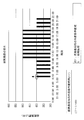
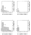
図15は、表示部5に表示するグラフを例示する図である。図11のグラフと同様に、縦軸には、総消費電力を表す変数Pを、横軸には、冷凍機#4の消費電力特性を表す変数aをとる。
図15に示すように、本変形例では、2つの論理式φ2’、φ2’’のそれぞれが満たす領域A2’、A2’’が色分け等により、互いに識別可能に表示される。図15においては、領域A2’、A2’’を斜線、網掛けで識別可能とするグラフを作成する。
ユーザは、図15に例示するグラフを参照して、新たに導入する冷凍機#4が稼働しない場合及び稼働する場合のそれぞれの領域を比較して、解析を行う。
例えば、冷凍機#4の消費電力特性aの値が小さい場合には、冷凍機#4を稼働させて他の効率の悪い冷凍機を停止させることで、稼働させない場合、すなわち冷凍機#1~#3を稼働させる場合よりも大幅に総消費電力Pを抑制できることがわかる(図15の※1)。
また、消費電力特性aの値が約0.295以上の領域では、冷凍機#4を稼働させない方が総消費電力P小さくできること、すなわち、新たに冷凍機#4を導入しても、総消費電力Pを抑制できないことがわかる(図15の※2)。
このように、本変形例によれば、新たに導入する設備を稼働するか否かが総消費エネルギーに与える影響や、新たに導入する設備の特性に応じて、省エネの観点からは新たに導入する設備または既存の設備のいずれを稼働させるべきかを容易に判断可能となる。
(変形例2)
上記の実施形態及び変形例1では、外部条件として、空調対象空間が相対的に高熱負荷である場合を設定している。これに対し、本変形例では、空調対象空間が相対的に低熱負荷である場合を設定して、低熱負荷時における導入する設備の特性と総消費エネルギーとの関係を表す論理式φを求めてグラフに描画する。
(変形例2)
上記の実施形態及び変形例1では、外部条件として、空調対象空間が相対的に高熱負荷である場合を設定している。これに対し、本変形例では、空調対象空間が相対的に低熱負荷である場合を設定して、低熱負荷時における導入する設備の特性と総消費エネルギーとの関係を表す論理式φを求めてグラフに描画する。
以下、本変形例について、上記の実施形態及び変形例1と異なる点を中心に説明する。エネルギー解析支援装置1の構成、入力される情報(システムモデル、設備モデル及び外部条件)については、上記の実施形態及び変形例1と同様であり、図1や図5~図7を参照して説明したとおりである。
エネルギー解析支援装置1は、図5~図7の情報が入力されると、上記の実施形態や変形例1と同様に、システムモデル数式、設備モデル数式及び外部条件数式を生成する。本変形例では、変形例1と同様に、新たに導入する冷凍機#4を稼働する場合及び稼働しない場合のそれぞれについて設備モデル数式F2’、F2’’を生成して、それぞれ冷凍機#4の消費電力特性aと総消費電力Pとの関係式を求める場合について説明する。
システムモデル数式F1については、上記の実施形態と同様であり、図8を参照して説明したとおりである。設備モデル数式F2’、F2’’については、変形例1で図12を参照して説明したとおりである。
図16は、本変形例において生成する外部条件数式を説明する図である。
本変形例では、エネルギー解析支援装置1の計算部11は、低熱負荷時の外部条件数式として、
F3’:=L=400
を生成する。このように、本変形例では熱負荷Lには、図16上側の時間帯別の空調対象空間の総熱負荷のグラフでは「6時~7時」「7時~8時」等の時間帯に設定されている、相対的に低い総熱負荷の値である400[kW]を設定する。
F3’:=L=400
を生成する。このように、本変形例では熱負荷Lには、図16上側の時間帯別の空調対象空間の総熱負荷のグラフでは「6時~7時」「7時~8時」等の時間帯に設定されている、相対的に低い総熱負荷の値である400[kW]を設定する。
計算部11は、システムモデル数式F1、2つの設備モデル数式F2’とF2’’、及び低熱負荷時の外部条件数式F3’を用いて、2つの一階述語論理式を生成する。
図17は、生成される2つの一階述語論理式ψ3’、ψ3’’を示す図である。
図17の2つの一階述語論理式ψ3’及びψ3’’は、それぞれ冷凍機#4を稼働しない場合及び稼働する場合の総消費電力に関する一階述語論理式である。計算部11は、図8のシステムモデル数式F1、図12の設備モデル数式F2’とF2’’、図16の外部条件数式F3’からそれぞれシステム全体を表現した式(F1∧F2’∧F3’)、(F1∧F2’’∧F3’)を生成する。存在記号(∃)を付与する変数は、上記の実施形態や変形例1と同様である。
ψ3’:= ∃P1∃P2∃P3∃P4 L∃L1∃L2∃L3∃L4((F1∧F2’∧F3’)
F1∧F2’∧F3’:=
P=P1+P2+P3+P4∧L=L1+L2+L3+L4
∧(P1=0.12*L1+ 16∧69<=L1<=125 ∨P1=0∧L1=0)
∧(P2=0.17*L2+21 ∧95<=L2<=175∨P2=0∧L2=0)
∧(P3=0.24*L3+26∧122<=L3<=212 ∨P3=0∧L3=0)
∧(P4=0∧L4=0)
∧L=400)
ψ3’’:=∃P1∃P2∃P3∃P4 ∃L∃L1∃L2∃L3∃L4(F1∧F2’’∧F3’)
F1∧F2’’∧F3’:=
P=P1+P2+P3+P4∧L=L1+L2+L3+L4
∧(P1=0.12*L1+ 16∧69<=L1<=125 ∨P1=0∧L1=0)
∧(P2=0.17*L2+21 ∧95<=L2<=175∨P2=0∧L2=0)
∧(P3=0.24*L3+26∧122<=L3<=212 ∨P3=0∧L3=0)
∧(P4=a*L4+15∧69<=L4<=212 ∧0.1<=a<=0.35)
∧L=400)
先の実施形態等においても説明したように、計算部11は、生成した一階述語論理式に限定記号消去アルゴリズムを適用し、冷凍機#4の消費電力特性を表す変数aと総消費電力を表す変数Pとの関係を表した論理式を得る。
ψ3’:= ∃P1∃P2∃P3∃P4 L∃L1∃L2∃L3∃L4((F1∧F2’∧F3’)
F1∧F2’∧F3’:=
P=P1+P2+P3+P4∧L=L1+L2+L3+L4
∧(P1=0.12*L1+ 16∧69<=L1<=125 ∨P1=0∧L1=0)
∧(P2=0.17*L2+21 ∧95<=L2<=175∨P2=0∧L2=0)
∧(P3=0.24*L3+26∧122<=L3<=212 ∨P3=0∧L3=0)
∧(P4=0∧L4=0)
∧L=400)
ψ3’’:=∃P1∃P2∃P3∃P4 ∃L∃L1∃L2∃L3∃L4(F1∧F2’’∧F3’)
F1∧F2’’∧F3’:=
P=P1+P2+P3+P4∧L=L1+L2+L3+L4
∧(P1=0.12*L1+ 16∧69<=L1<=125 ∨P1=0∧L1=0)
∧(P2=0.17*L2+21 ∧95<=L2<=175∨P2=0∧L2=0)
∧(P3=0.24*L3+26∧122<=L3<=212 ∨P3=0∧L3=0)
∧(P4=a*L4+15∧69<=L4<=212 ∧0.1<=a<=0.35)
∧L=400)
先の実施形態等においても説明したように、計算部11は、生成した一階述語論理式に限定記号消去アルゴリズムを適用し、冷凍機#4の消費電力特性を表す変数aと総消費電力を表す変数Pとの関係を表した論理式を得る。
図18は、一階述語論理式ψ3’、ψ3’’に限定記号消去アルゴリズムを適用して得られる論理式φ3’、φ3’’を示す図である。
φ3’:=QE[ψ3’]
(φ3’:=13329/100<=P<=14239/100)
φ3’’:=QE[ψ3’’]
(φ3:=(-35+a<=0∧1/10-a<=0∧2297/25+188*a-P=0∧-P<0)
∨(-35+a<=0∧1/10-a<=0∧2532/25+153*a-P=0∧-P<0)
∨(-35+a<=0∧1/10-a<=0∧2904/25+119*a-P=0∧-P<0)
∨(-35+a<=0∧1/10-a<=0∧2364/25+209*a-P=0∧-P<0)
∨(-35+a<=0∧1/10-a<=0∧12103/100+103*a-P=0∧-P<0)
∨(-35+a=0∧1/10-a<=0∧12903/100+93*a-P=0∧-P<0)
∨(-35+a<=0∧1/10-a<=0∧10743/100+183*a-P=0∧-P<0)
∨(-35+a<=0∧1/10-a<=0∧387/4+100*a-P=0∧-P<0)
∨(-35+a<=0∧1/10-a<=0∧1663/20+180*a-P=0∧-P<0)
∨(-35+a<=0∧1/10-a<=0∧9003/100+156*a-P=0∧-P<0) ...(以下省略))
論理式φ3’、φ3’’は、それぞれ低熱負荷時において冷凍機#4を稼働しない場合と稼働する場合の冷凍機#4の消費電力特性aと総消費電力Pとが満たす関係式である。出力部12は、計算部11から論理式φ3’、φ3’’を受け取ると、これに基づき2つの式が満たす領域を比較可能なグラフを生成し、これを表示部5に出力する。
φ3’:=QE[ψ3’]
(φ3’:=13329/100<=P<=14239/100)
φ3’’:=QE[ψ3’’]
(φ3:=(-35+a<=0∧1/10-a<=0∧2297/25+188*a-P=0∧-P<0)
∨(-35+a<=0∧1/10-a<=0∧2532/25+153*a-P=0∧-P<0)
∨(-35+a<=0∧1/10-a<=0∧2904/25+119*a-P=0∧-P<0)
∨(-35+a<=0∧1/10-a<=0∧2364/25+209*a-P=0∧-P<0)
∨(-35+a<=0∧1/10-a<=0∧12103/100+103*a-P=0∧-P<0)
∨(-35+a=0∧1/10-a<=0∧12903/100+93*a-P=0∧-P<0)
∨(-35+a<=0∧1/10-a<=0∧10743/100+183*a-P=0∧-P<0)
∨(-35+a<=0∧1/10-a<=0∧387/4+100*a-P=0∧-P<0)
∨(-35+a<=0∧1/10-a<=0∧1663/20+180*a-P=0∧-P<0)
∨(-35+a<=0∧1/10-a<=0∧9003/100+156*a-P=0∧-P<0) ...(以下省略))
論理式φ3’、φ3’’は、それぞれ低熱負荷時において冷凍機#4を稼働しない場合と稼働する場合の冷凍機#4の消費電力特性aと総消費電力Pとが満たす関係式である。出力部12は、計算部11から論理式φ3’、φ3’’を受け取ると、これに基づき2つの式が満たす領域を比較可能なグラフを生成し、これを表示部5に出力する。
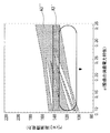
図19は、表示部5に表示するグラフを例示する図である。図11や図15のグラフと同様に、縦軸は、総消費電力Pを、横軸は、冷凍機#4の消費電力特性aをとる。
図19に示すように、本変形例では、2つの論理式φ3’、φ3’’のそれぞれが満たす領域A3’を網掛けで、A3’’を斜線で識別可能とするグラフを作成する。ユーザは、図19に例示するグラフを参照して、低熱負荷時に新たに導入する冷凍機#4を稼働しない場合及び稼働する場合のそれぞれの領域を比較して、解析を行う。
例えば、図19においては矢印で指し示す領域のように、冷凍機#4の消費電力特性aの範囲が0.10から035の領域(図15に示すグラフの全域)では、冷凍機#4を稼働させた方が総消費電力Pを抑制できることがわかる。
なお、図19においては、低熱負荷時における冷凍機#4の消費電力特性aと総消費電力Pとの関係を、冷凍機#4を稼働しない場合と稼働する場合とで識別可能なグラフを例示している。この他にも、例えば変形例1で求めた図14の論理式φ2’、φ2’’を用いて、高熱負荷時と低熱負荷時とを比較するグラフ等、更に各種の変形例が考えられる。
このように、本変形例によれば、外部条件を変更した場合であっても、新たに導入する設備の特性と総消費エネルギーとの関係がどのようになるかについて容易に判断可能となる。
(変形例3)
上記の実施形態及び変形例1、2では、設備(冷凍機)の特性の一つである消費電力特性を表す変数aと総消費電力Pとの関係を求めている。これに対し、本変形例では、新たに導入する冷凍機の消費電力特性以外の特性を表す変数と総消費電力Pとの関係を求める。
(変形例3)
上記の実施形態及び変形例1、2では、設備(冷凍機)の特性の一つである消費電力特性を表す変数aと総消費電力Pとの関係を求めている。これに対し、本変形例では、新たに導入する冷凍機の消費電力特性以外の特性を表す変数と総消費電力Pとの関係を求める。
以下、本変形例について、上記の実施形態等と異なる点を中心に説明する。エネルギー解析支援装置1の構成、入力される情報については、上記の実施形態等と同様であり、図1や図5~図7を参照して説明したとおりである。
エネルギー解析支援装置1は、図5~図7の情報が入力されると、上記の実施形態等と同様に、システムモデル数式、設備モデル数式及び外部条件数式を生成する。システムモデル数式F1と外部条件数式F3については、いずれも図8を参照して説明したとおりである。
図20は、本変形例において生成する設備モデル数式を説明する図である。
本変形例では、冷凍機#4の熱負荷の上限を表す変数bを用いて、冷凍機#4を稼働する場合における設備モデル数式F2’’’を生成する。冷凍機#4の消費電力特性については、固定値0.16とする。
F2’’’:=(P1=0.12*L1+ 16∧69<=L1<=125∨P1=0∧L1=0)
∧(P2=0.17*L2+21∧95<=L2<=175∨P2=0∧L2=0)
∧(P3=0.24*L3+26∧122<=L3<=212∨P3=0∧L3=0)
∧(P4=0.16*L4+15∧69<=L4<=b∧69<=b<=212)
上の設備モデル数式F2’’’のうち、冷凍機#4の特性を表す数式は、以下のとおりである。
(P4=0.16*L4+15∧69<=L4<=b∧69<=b<=212)
このうち、変数bを含む第2の式「69<=L4<=b」は、熱負荷L4が下限値69以上且つ上限値b以下であることを表す。第3の式「69<=b<=212」は、熱負荷L4の上限bが69以上かつ212以下の値をとることを表す。
F2’’’:=(P1=0.12*L1+ 16∧69<=L1<=125∨P1=0∧L1=0)
∧(P2=0.17*L2+21∧95<=L2<=175∨P2=0∧L2=0)
∧(P3=0.24*L3+26∧122<=L3<=212∨P3=0∧L3=0)
∧(P4=0.16*L4+15∧69<=L4<=b∧69<=b<=212)
上の設備モデル数式F2’’’のうち、冷凍機#4の特性を表す数式は、以下のとおりである。
(P4=0.16*L4+15∧69<=L4<=b∧69<=b<=212)
このうち、変数bを含む第2の式「69<=L4<=b」は、熱負荷L4が下限値69以上且つ上限値b以下であることを表す。第3の式「69<=b<=212」は、熱負荷L4の上限bが69以上かつ212以下の値をとることを表す。
計算部11は、システムモデル数式F1、設備モデル数式F2’’’及び外部条件数式F3を用いて、一階述語論理式を生成する。
図21は、生成される一階述語論理式ψ4’’を示す図である。
図21の一階述語論理式ψ4’’は、冷凍機#4の熱負荷の上限bを変数とする一階述語論理式である。計算部11は、図8のシステムモデル数式F1、図20の設備モデルF2’’’及び図8の外部条件数式からシステム全体を現した式(F1∧F2’’’∧F3)を生成し、変数b及びP以外の変数に存在記号(∃)を付与して、論理式ψ4’’を生成する。
ψ4’’:=∃P1∃P2∃P3∃P4 ∃L∃L1∃L2∃L3∃L4(F1∧F2’’’∧F3)
(F1∧F2’’’∧F3:=
P=P1+P2+P3+P4∧L=L1+L2+L3+L4
∧(P1=0.12*L1+ 16∧69<=L1<=125∨P1=0∧L1=0)
∧(P2=0.17*L2+21 ∧95<=L2<=175∨P2=0∧L2=0)
∧(P3=0.24*L3+26∧122<=L3<=212∨P3=0∧L3=0)
∧(P4=0.16*L4+15∧69<=L4<=b∧69<=b<=212)
∧L=500))
計算部11は、生成した一階述語論理式に限定記号消去アルゴリズムを適用し、冷凍機#4の熱負荷L4の上限を表す変数bと総消費電力を表す変数Pとの関係を表した論理式を得る。
ψ4’’:=∃P1∃P2∃P3∃P4 ∃L∃L1∃L2∃L3∃L4(F1∧F2’’’∧F3)
(F1∧F2’’’∧F3:=
P=P1+P2+P3+P4∧L=L1+L2+L3+L4
∧(P1=0.12*L1+ 16∧69<=L1<=125∨P1=0∧L1=0)
∧(P2=0.17*L2+21 ∧95<=L2<=175∨P2=0∧L2=0)
∧(P3=0.24*L3+26∧122<=L3<=212∨P3=0∧L3=0)
∧(P4=0.16*L4+15∧69<=L4<=b∧69<=b<=212)
∧L=500))
計算部11は、生成した一階述語論理式に限定記号消去アルゴリズムを適用し、冷凍機#4の熱負荷L4の上限を表す変数bと総消費電力を表す変数Pとの関係を表した論理式を得る。
図22は、一階述語論理式ψ4’’に限定記号消去アルゴリズムを適用して得られる論理式φ4’’を示す図である。
φ4’’:=QE[ψ4’’]
(φ4’’:=(-212+b<=0∧163-b<=0∧-3724/25+P=0)
∨(-212+b<=0∧200-b<=0∧-515/4+P=0)
∨(-212+b<=0∧203-b<=0∧-15351/100+P=0)
∨(-212+b<=0∧113-b<=0∧-16071/100+P=0)
∨(-212+b<=0∧193-b<=0∧-15991/100+P=0)
∨(-212+b<=0∧69-b<=0∧-375-4*b+25*P<=0∧-95+P=0)
∨(-212+b<=0∧69-b<=0∧-3439/20+P<=0∧16523/100-P<=0)
∨(-212+b<=0∧69-b<=0∧-17083/100+P<=0∧16523/100-P<=0)
∨(-212+b<=0∧69-b<=0∧-1737/10+P<=0∧3419/20-P<=0)
∨(-212+b<=0∧69-b<=0∧-3419/20+P<=0∧17083/100-P<=0)
∨(-212+b<=0∧69-b<=0∧-1737/10+P<=0∧3439/20-P<=0)
∨(-212+b<=0∧163-b<=0∧3561+b-25*P=0∧-P<0)
∨(-212+b<=0∧163-b<=0∧-P<0∧-4050+2*b+25*P= 0)...(以下省略))
論理式φ4’’は、冷凍機#4の熱負荷L4の上限bと総消費電力Pとの関係を表す。出力部12は、計算部11から論理式φ4’’を受け取ると、これに基づき論理式φ4’’が満たす領域を表すグラフを生成し、これを表示部5に出力する。
φ4’’:=QE[ψ4’’]
(φ4’’:=(-212+b<=0∧163-b<=0∧-3724/25+P=0)
∨(-212+b<=0∧200-b<=0∧-515/4+P=0)
∨(-212+b<=0∧203-b<=0∧-15351/100+P=0)
∨(-212+b<=0∧113-b<=0∧-16071/100+P=0)
∨(-212+b<=0∧193-b<=0∧-15991/100+P=0)
∨(-212+b<=0∧69-b<=0∧-375-4*b+25*P<=0∧-95+P=0)
∨(-212+b<=0∧69-b<=0∧-3439/20+P<=0∧16523/100-P<=0)
∨(-212+b<=0∧69-b<=0∧-17083/100+P<=0∧16523/100-P<=0)
∨(-212+b<=0∧69-b<=0∧-1737/10+P<=0∧3419/20-P<=0)
∨(-212+b<=0∧69-b<=0∧-3419/20+P<=0∧17083/100-P<=0)
∨(-212+b<=0∧69-b<=0∧-1737/10+P<=0∧3439/20-P<=0)
∨(-212+b<=0∧163-b<=0∧3561+b-25*P=0∧-P<0)
∨(-212+b<=0∧163-b<=0∧-P<0∧-4050+2*b+25*P= 0)...(以下省略))
論理式φ4’’は、冷凍機#4の熱負荷L4の上限bと総消費電力Pとの関係を表す。出力部12は、計算部11から論理式φ4’’を受け取ると、これに基づき論理式φ4’’が満たす領域を表すグラフを生成し、これを表示部5に出力する。
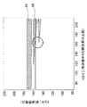
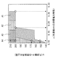
図23は、表示部5に表示するグラフを例示する図である。図11、15及び図19のグラフと同様に、縦軸は、総消費電力Pをとる。横軸では、冷凍機#4の熱負荷L4の上限bをとる。
図23に示すグラフのうち、領域A4’’は、論理式φ4’’の変数bとPとが満たす領域を斜線で表している。図20の設備モデル数式F2’’’を生成する方法において記載したとおり、領域A4’’は、冷凍機#4を稼働する場合における冷凍機#4の熱負荷L4の上限bと総消費電力Pとが満たす領域である。
これに対し、図23の領域A4’は、冷凍機#4を稼働しない場合における冷凍機#4の熱負荷L4の上限bと総消費電力Pとが満たす領域である。領域A4’は、上記の変形例2にて冷凍機#4を稼働しない場合について求めた論理式φ2’を利用している。論理式φ2’は、一階述語論理式ψ2’から限定記号を消去することにより得られ、一階述語論理式ψ2’は、システムモデル数式F1、設備モデル数式F2’及び外部条件数式F3を用いて生成している。
ここで、図12の式(12-1)に示すように、設備モデル数式F2’は、冷凍機#4の熱負荷L4の上限bには依存しない。このため、設備モデルF2’を用いて求めた論理式φ2’もまた、変数bによらず、したがって、論理式φ2’は、本変形例の冷凍機#4の熱負荷L4の上限bと総消費電力Pとの関係を表していると言うことができる。
ユーザは、図23に例示するグラフを参照して、冷凍機#4を稼働させる場合及び稼働しない場合のそれぞれの領域を比較して、解析を行う。
例えば、図中丸印で囲った領域を参照すると、冷凍機#4の熱負荷L4の上限bが約160以上になると、冷凍機#4を導入し稼働した方が、稼働しない場合よりも総消費電力Pを抑制できることがわかる。
このように、本変形例によれば、新たに導入する設備の消費電力特性以外の各種の特性についても、総消費エネルギーとの関係を表した論理式を求めることができ、これにより、更にユーザのプラントの解析に資する。
従来技術によれば、設備の制約条件(上記の例では解析対象の冷凍機#4の総熱負荷の上限)を変更した場合には、最適な消費エネルギーがどのように変化するかが判然とせず、省エネを実現するためにはどのような制約条件下で設備を運用する必要があるかがわからない、ということがあった。このような場合であっても、本実施形態に係るエネルギー解析支援装置1を用いて解析を行うことで、設備を運用する制約条件を緩和することで省エネ化ができる場合等を検証することが可能となる。
<第2の実施形態>
上記の第1の実施形態に係るエネルギー解析支援装置1は、生成した一階述語論理式から限定記号を消去し、設備の特性と総消費エネルギーとの関係を表す論理式を得てこれからグラフを生成している。これに対し、本実施形態においては、限定記号を消去した結果得られる論理式が、設備の特性同士の間で満たされる関係を表している点で異なる。
<第2の実施形態>
上記の第1の実施形態に係るエネルギー解析支援装置1は、生成した一階述語論理式から限定記号を消去し、設備の特性と総消費エネルギーとの関係を表す論理式を得てこれからグラフを生成している。これに対し、本実施形態においては、限定記号を消去した結果得られる論理式が、設備の特性同士の間で満たされる関係を表している点で異なる。
以下、本実施形態に係るエネルギー解析支援装置1について、上記の第1の実施形態と異なる点を中心に説明する。
本実施形態に係るエネルギー解析支援装置1の構成図は、図1の第1の実施形態に係るそれと同様である。エネルギー解析支援装置1は、計算部11と出力部12とを有し、キーボード2Aやポインティングデバイス2B等の入力部2やモニタ等の表示部5と接続される。
エネルギー解析支援装置1は、第1の実施形態と同様に、入力部2を介してシステムモデル、設備モデル及び外部条件の入力を受け付ける。入力されるこれらの情報についても、上記の実施形態と同様であり、図5~図7等を参照して説明したとおりである。
本実施形態に係るエネルギー解析支援装置1は、入力された情報からシステムモデル数式等の数式を生成して、一階述語論理式を生成し、生成した一階述語論理式から限定記号を消去して論理式を得る。上記のとおり、本実施形態において限定記号を消去して得られる論理式は、それぞれがプラントの設備の特性を表す変数同士が満たす関係を表している。エネルギー解析支援装置1は、得られた論理式に基づきグラフを生成して表示部5に出力し、表示をさせる。
図24は、計算部11における動作フローを示す図である。
図2の第1の実施形態の動作フローと比較すると、ステップS11については、図2のステップS1と同様である。
ステップS12で、計算部11は、プラントの運転状態に関する一階述語論理式を生成する。ここで、「プラントの運転状態に関する一階述語論理式」は、図2のステップS2で生成する「総消費エネルギーに関する一階述語論理式」と比較すると、存在記号を付与する変数が異なっている。
ステップS13及びステップS14では、図2のステップS3及びステップS4と同様の処理を実施する。すなわち、ステップS12で生成した一階述語論理式から限定記号を消去した論理式を計算し、計算により得られたプラント解析数式を出力部12に出力し、処理を終了する。
図25は、本実施形態において計算部11が生成する一階述語論理式及び一階述語論理式から限定記号を消去して得られる論理式について説明する図である。
計算部11は、上記の第1の実施形態と同様に、システムモデル数式F1、設備モデルF2及び外部条件数式F3iを論理積(∧)で結合する(図25の式(25-2))。そして、本実施形態においては、計算部11は、設備の特性を表す2つの変数a、b以外の変数に対して存在記号(∃)を付与して(図25の(25-1))一階述語論理式ψiを生成する。
ψi:=∃P∃P1,...,∃PN∃L∃L1,...,∃LN(F1∧F2∧F3i)
外部条件数式F3iの添え字「i」は、プラント解析のため予め用意されている複数の外部条件数式を互いに識別するために付されている。実施例では、複数の外部条件数式を生成し、その数を「I」とする。計算部11は、外部条件数式F3i(i=1,2,…,I)の数(I)だけ一階述語論理式ψiを生成する。
ψi:=∃P∃P1,...,∃PN∃L∃L1,...,∃LN(F1∧F2∧F3i)
外部条件数式F3iの添え字「i」は、プラント解析のため予め用意されている複数の外部条件数式を互いに識別するために付されている。実施例では、複数の外部条件数式を生成し、その数を「I」とする。計算部11は、外部条件数式F3i(i=1,2,…,I)の数(I)だけ一階述語論理式ψiを生成する。
このように、互いに異なる外部条件数式は、それぞれプラントの運転状態を表すことから、本実施形態において生成する一階述語論理式ψiを、以下においては、「プラントの運転状態に関する一階述語論理式」ともいう。
計算部11は、I個のプラントの運転状態に関する一階述語論理式ψiのそれぞれに限定記号消去アルゴリズムを適用し、設備の特性を表す変数a、bが満たす関係を表した論理式φiを得て、これを出力部12に出力する。
φi:=QE[ψi]
(φi:=(aとbに関する数式))
出力部12は、計算部11が得たI個の論理式φi(i=1,2,…,I)より、2つの設備の特性を表す変数a、bが満たす領域を表したグラフを生成する。出力部12は、これをエネルギー解析支援装置1において解析支援処理を実施した結果得られた情報として表示部5に出力する。表示部5は、出力部12から入力された情報に基づき、エネルギー解析支援装置1における計算結果を表示する。
φi:=QE[ψi]
(φi:=(aとbに関する数式))
出力部12は、計算部11が得たI個の論理式φi(i=1,2,…,I)より、2つの設備の特性を表す変数a、bが満たす領域を表したグラフを生成する。出力部12は、これをエネルギー解析支援装置1において解析支援処理を実施した結果得られた情報として表示部5に出力する。表示部5は、出力部12から入力された情報に基づき、エネルギー解析支援装置1における計算結果を表示する。
図26は、出力部12が生成するグラフを模式的に示す図である。本実施形態においては、一方の軸(横軸)には、設備の特性を表す変数aを、他方の軸(縦軸)には、設備の特性を表す他の変数bをとる。そして、図26に模式的に示すように、プラントの運転状態ごと、すなわち、複数の外部条件数式F3iのそれぞれについて求めた論理式φiが満たす領域が、色分け等により可視化される。
以下、本実施形態に係るエネルギー解析支援装置1が入力された各種モデルを用いてどのように各種数式の計算を行い、計算結果のグラフを得るかについて、第1の実施形態と同様に、具体例を用いつつ、上記第1の実施形態と異なる点を中心に説明する。
プラントのシステムモデル及び設備モデルについては、第1の実施形態と同様であり、図5及び図6に示すとおりである。
図27は、外部条件を例示する図である。
第1の外部条件は、空調システム全体の総熱負荷Lである。設例では、総熱負荷Lを500[kW]に設定する。
第2の外部条件は、空調システム全体の総消費電力Pである。設例では、第2の外部条件として、4とおりを設定し、それぞれ150[kW]以下、140[kW]以下、130[kW]以下及び120[kW]以下とする。
図28は、計算部11が図5のシステムモデル、図6の設備モデル及び図27の外部条件から生成する数式群を例示する図である。
システムモデル数式F1については、第1の実施形態と同様であり、図8の数式F1と同様である。
F1:=P=P1+P2+P3+P4∧L=L1+L2+L3+L4
設備モデル数式F2については、新たに導入する冷凍機#4の特性を表す変数のうち、消費電力特性については、第1の実施形態と同様に、「変数a」で表す。冷凍機#4の熱負荷L4の上限については、「変数b」で表す。
F2:=(P1=0.12*L1+16∧69<=L1<=125∨P1=0∧L1=0)
∧(P2=0.17*L2+21∧95<=L2<=175∨P2=0∧L2=0)
∧(P3=0.24*L3+26∧122<=L3<=212∨P3=0∧L3=0)
∧(P4=a*L4+15∧69<=L4<=b∧0.1<=a<=0.35∧69<=b<=212∨P4=0∧L4=0)
外部条件数式F3i(i=1,2,3,4)については、第1の外部条件及び第2の外部条件がいずれも成立する場合の数式を生成する。すなわち、第1の外部条件の式と第2の外部条件の式とを論理積(∧)で結合して、外部条件数式F3iとする。
F31:=L=500∧P<=150
F32:=L=500∧P<=140
F33:=L=500∧P<=130
F34:=L=500∧P<=120
図29は、図28の数式群F1、F2、F3iから一階述語論理式ψiを生成する方法を説明する図である。
F1:=P=P1+P2+P3+P4∧L=L1+L2+L3+L4
設備モデル数式F2については、新たに導入する冷凍機#4の特性を表す変数のうち、消費電力特性については、第1の実施形態と同様に、「変数a」で表す。冷凍機#4の熱負荷L4の上限については、「変数b」で表す。
F2:=(P1=0.12*L1+16∧69<=L1<=125∨P1=0∧L1=0)
∧(P2=0.17*L2+21∧95<=L2<=175∨P2=0∧L2=0)
∧(P3=0.24*L3+26∧122<=L3<=212∨P3=0∧L3=0)
∧(P4=a*L4+15∧69<=L4<=b∧0.1<=a<=0.35∧69<=b<=212∨P4=0∧L4=0)
外部条件数式F3i(i=1,2,3,4)については、第1の外部条件及び第2の外部条件がいずれも成立する場合の数式を生成する。すなわち、第1の外部条件の式と第2の外部条件の式とを論理積(∧)で結合して、外部条件数式F3iとする。
F31:=L=500∧P<=150
F32:=L=500∧P<=140
F33:=L=500∧P<=130
F34:=L=500∧P<=120
図29は、図28の数式群F1、F2、F3iから一階述語論理式ψiを生成する方法を説明する図である。
先に図25の説明においても述べたとおり、計算部11は、生成した図28の数式F1、F2、F3iを論理積(∧)で結合し、変数a、b以外の変数に存在記号(∃)を付与して、一階述語論理式ψiを生成する。図29においては、4とおりの外部条件のうち、i=1の外部条件、具体的には、空調システムの総熱負荷Lが500[kW]で、空調システムの総消費電力Pが150[kW]以下であることを外部条件とする場合の一階述語論理式ψ1を例示する。他の3とおりの外部条件の場合の一階述語論理式ψ2~ψ4の具体的な数式については、外部条件数式F3i以外は、ψ1と共通であるため、図29においては記載を省略している。すなわち、図29のψ1の式の外部条件数式F31を上記のF32~F34に置き換えた式が、一階述語論理式ψ2~ψ4である。
ψ1:=∃P∃P1∃P2∃P3∃P4∃L∃L1∃L2∃L3∃L4(F1∧F2∧F31)
ψ2:=∃P∃P1∃P2∃P3∃P4∃L∃L1∃L2∃L3∃L4(F1∧F2∧F32)
ψ3:=∃P∃P1∃P2∃P3∃P4∃L∃L1∃L2∃L3∃L4(F1∧F2∧F33)
ψ4:=∃P∃P1∃P2∃P3∃P4∃L∃L1∃L2∃L3∃L4(F1∧F2∧F34)
F1∧F2∧F31:=
P=P1+P2+P3+P4∧L=L1+L2+L3+L4
∧(P1=0.12*L1+16∧69<=L1<=125∨P1=0∧L1=0)
∧(P2=0.17*L2+21∧95<=L2<=175∨P2=0∧L2=0)
∧(P3=0.24*L3+26∧122<=L3<=212∨P3=0∧L3=0)
∧(P4=a*L4+15∧69<=L4<=b∧0.1<=a<=0.35∧69<=b<= 212∨P4=0∧L4=0)
∧L=500∧P<=150)
図30は、一階述語論理式ψ1~ψ4から限定記号を消去して得られる論理式φ1~φ4を示す図である。
ψ1:=∃P∃P1∃P2∃P3∃P4∃L∃L1∃L2∃L3∃L4(F1∧F2∧F31)
ψ2:=∃P∃P1∃P2∃P3∃P4∃L∃L1∃L2∃L3∃L4(F1∧F2∧F32)
ψ3:=∃P∃P1∃P2∃P3∃P4∃L∃L1∃L2∃L3∃L4(F1∧F2∧F33)
ψ4:=∃P∃P1∃P2∃P3∃P4∃L∃L1∃L2∃L3∃L4(F1∧F2∧F34)
F1∧F2∧F31:=
P=P1+P2+P3+P4∧L=L1+L2+L3+L4
∧(P1=0.12*L1+16∧69<=L1<=125∨P1=0∧L1=0)
∧(P2=0.17*L2+21∧95<=L2<=175∨P2=0∧L2=0)
∧(P3=0.24*L3+26∧122<=L3<=212∨P3=0∧L3=0)
∧(P4=a*L4+15∧69<=L4<=b∧0.1<=a<=0.35∧69<=b<= 212∨P4=0∧L4=0)
∧L=500∧P<=150)
図30は、一階述語論理式ψ1~ψ4から限定記号を消去して得られる論理式φ1~φ4を示す図である。
計算部11は、生成した一階述語論理式ψ1~ψ4のそれぞれに限定記号消去アルゴリズム(QE[])を適用して、存在記号の付与された変数を消去した論理式φ1~φ4を得る。論理式φ1~φ4は、冷凍機#4の消費電力特性aと、熱負荷L4の上限bとが満たす関係式からなる。
φ1:=QE[ψ1]
(φ1:=(-213/800+a=0∧-212+b<=0∧200-b<=0)∨(-678/4075+a=0∧-212+b<=0∧163-b<=0)∨(-2897/20300+a=0∧-212+b<=0∧203-b<=0)∨(-2097/19300+a=0∧-212+b<=0∧193-b<=0)∨(-3/25+a<0∧1/10-a<=0∧-212+b<=0∧200-b<=0) ...以下省略)
φ2:=QE[ψ2]
(φ2:=(-173/800+a=0∧-212+b<=0∧200-b<=0)∨(-428/4075+a=0∧-212+b<=0∧163-b<=0)∨(-3/25+a<0∧1/10-a<=0∧-212+b<=0∧200-b<=0)∨(-173/800+a<=0∧1/10-a<=0∧-212+b<=0∧200-b<=0)∨(-428/4075+a<=0∧1/10-a<=0∧-212+b<=0∧163-b<=0)...以下省略)
φ3:=QE[ψ3]
(φ3:=(-133/800+a=0∧-212+b<=0∧200-b<=0)∨(-3/25+a<0∧1/10-a<=0∧-212+b<=0∧200-b<=0)∨(-133/800+a<=0∧1/10-a<=0∧-212+b<=0∧200-b<=0)∨(-133/800+a<=0∧3/25-a<0∧-212+b<=0∧200-b<=0)...以下省略)
φ4:=QE[ψ4]
(φ4:=(-93/800+a=0∧-212+b<=0∧200-b<=0)∨(-93/800+a<=0∧1/10-a<=0∧-212+b<=0∧200-b<=0)∨(-7/20+a<=0∧1/10-a<=0∧-212+b<=0∧163-b<0∧1050-6*b+25*a*b=0)∨(-7/20+a<=0∧1/10-a<=0∧-212+b<=0∧163-b<0∧1050-6*b+25*a*b<=0)...以下省略)
図31は、表示部5に表示する画面の一例を示す図であり、各論理式φ1~φ4が満たす領域A1~A4をそれぞれグラフで示している。縦軸には、冷凍機#4の熱負荷L4の上限bを、横軸には冷凍機#4の消費電力特性aをとる。図31の領域A1~A4は、それぞれ空調システムの総消費電力Pを150、140、130、120[kW]以下とするために必要な冷凍機#4の設備能力を表している。
φ1:=QE[ψ1]
(φ1:=(-213/800+a=0∧-212+b<=0∧200-b<=0)∨(-678/4075+a=0∧-212+b<=0∧163-b<=0)∨(-2897/20300+a=0∧-212+b<=0∧203-b<=0)∨(-2097/19300+a=0∧-212+b<=0∧193-b<=0)∨(-3/25+a<0∧1/10-a<=0∧-212+b<=0∧200-b<=0) ...以下省略)
φ2:=QE[ψ2]
(φ2:=(-173/800+a=0∧-212+b<=0∧200-b<=0)∨(-428/4075+a=0∧-212+b<=0∧163-b<=0)∨(-3/25+a<0∧1/10-a<=0∧-212+b<=0∧200-b<=0)∨(-173/800+a<=0∧1/10-a<=0∧-212+b<=0∧200-b<=0)∨(-428/4075+a<=0∧1/10-a<=0∧-212+b<=0∧163-b<=0)...以下省略)
φ3:=QE[ψ3]
(φ3:=(-133/800+a=0∧-212+b<=0∧200-b<=0)∨(-3/25+a<0∧1/10-a<=0∧-212+b<=0∧200-b<=0)∨(-133/800+a<=0∧1/10-a<=0∧-212+b<=0∧200-b<=0)∨(-133/800+a<=0∧3/25-a<0∧-212+b<=0∧200-b<=0)...以下省略)
φ4:=QE[ψ4]
(φ4:=(-93/800+a=0∧-212+b<=0∧200-b<=0)∨(-93/800+a<=0∧1/10-a<=0∧-212+b<=0∧200-b<=0)∨(-7/20+a<=0∧1/10-a<=0∧-212+b<=0∧163-b<0∧1050-6*b+25*a*b=0)∨(-7/20+a<=0∧1/10-a<=0∧-212+b<=0∧163-b<0∧1050-6*b+25*a*b<=0)...以下省略)
図31は、表示部5に表示する画面の一例を示す図であり、各論理式φ1~φ4が満たす領域A1~A4をそれぞれグラフで示している。縦軸には、冷凍機#4の熱負荷L4の上限bを、横軸には冷凍機#4の消費電力特性aをとる。図31の領域A1~A4は、それぞれ空調システムの総消費電力Pを150、140、130、120[kW]以下とするために必要な冷凍機#4の設備能力を表している。
図31に示すように、外部条件により、冷凍機#4の消費電力特性aとその熱負荷L4の上限bとが満たす領域A1~A4は、範囲が異なる。ユーザは、例えば図31の4つのグラフを比較しながら、冷凍機#4の消費電力特性aと熱負荷L4の上限bという互いに相関のある特性に応じて総消費電力Pがどのように変わるかを検討することができる。
領域A1~A4は、図31に例示するようにそれぞれを画面上に並べて配置させてもよいし、1つのグラフに各領域のどのあたりが重複しているかを視認可能に表示させてもよい。
図32は、表示部5に表示する画面の他の例を示す図であり、各論理式φ1~φ4が満たす領域A1~A4を色分け等により識別可能に表示している。図32の例では、斜線や網掛け等により各領域A1~A4をユーザが識別可能に表示している。
ユーザは、図32に例示するグラフを参照して、例えば、新たに導入する冷凍機#4の消費電力特性aが0.11のとき、総消費電力Pを所定値以下に抑制しようとする場合の熱負荷L4の上限値を確認する。総消費電力を150[kW]以下にするには、冷凍機#4の熱負荷の上限を152[kW]以上にする必要があることがわかる。同様に、総消費電力を140[kW]以下にするには、当該上限を168[kW]以上に、総消費電力を130[kW]以下にするには、当該上限を200[kW]以上にする必要があることがわかる。
また、冷凍機#4の熱負荷の上限bが200[kW]以上の範囲で総消費電力を所定値以下に抑制しようとする場合の冷凍機#4の消費電力特性aの最適な値を決定することができる。熱負荷の上限が200[kW]以上の条件の下で、総消費電力を150[kW]以下にするには、消費電力特性aを0.27以下にすればよいことがわかる。同様に、同条件の下で総消費電力を140[kW]以下にするには、消費電力特性aを0.18以下にすればよいことがわかる。
このように、本実施形態に係るエネルギー解析支援装置1によれば、相関のある複数の設備の特性間の関係を表した式が得られ、これにより、プラントの総消費電力がどのように変わるかを可視化できる。ユーザにとっては、可視化した結果を用いて、例えばどのような効率及び制約条件を備えた設備を導入すれば省エネ効果がどの程度見込めるのかの検討が容易になる。
本実施形態では、新たに導入する設備の制約条件(上記の例では熱負荷の上限)を一方の変数bに設定して、これを含む論理式φiを得てこれを解析用にユーザに提供している。従来は、ある設備の制約条件を変えた場合には、最適な消費エネルギーがどのように変化するかがわからなかったため、省エネを実現するには、設備をどのような制約条件下で運用する必要があるかもわからなかった。しかし、本実施形態に係るエネルギー解析支援装置1によれば、例えば制約条件を緩和した(上記の例では熱負荷の上限を上げた)場合には省エネを実現できることがあるが、そのような状態についても検証することが可能となる。
ところで、図1のエネルギー解析支援装置1は、例えば、図33に示すような情報処理装置(コンピュータ)を用いて構成することができる。図33の情報処理装置は、CPU(中央処理装置)1001、メモリ1002、入力装置1003、出力装置1004、外部記憶装置1005、媒体駆動装置1006、ネットワーク接続装置1007を備え、それらはバス1008により互いに接続されている。
メモリ1002は、例えば、ROM(read only memory)、RAM(random access memory)等を含み、処理に用いられるプログラムおよびデータを格納する。CPU1001は、メモリ1002を利用してプログラムを実行することにより、必要な処理を行う。
図1の計算部11及び出力部12は、メモリ1002に格納されたプログラムを実行することにより実現される機能に対応する。
入力装置1003は、例えば、キーボード、ポインティングデバイス、タッチパネル等であり、ネットワーク管理者等のオペレータからの指示や情報の入力に用いられる。出力装置1004は、例えば、ディスプレイ、プリンタ、スピーカ等であり、ユーザへの問い合わせ、アラーム、処理結果等の出力に用いられる。
外部記憶装置1005は、例えば、磁気ディスク装置、光ディスク装置、光磁気ディスク装置、テープ装置等である。情報処理装置は、この外部記憶装置1005に、上記プログラムおよびデータを格納しておき、必要に応じて、それらをメモリ1002にロードして使用する。
媒体駆動装置1006は、可搬記録媒体1009を駆動し、その記録内容にアクセスする。可搬記録媒体1009は、メモリカード、フレキシブルディスク、CD-ROM(compact disk read only memory )、光ディスク、光磁気ディスク等の任意のコンピュータ読み取り可能な記録媒体である。オペレータは、この可搬記録媒体1009に上記プログラムおよびデータを格納しておき、必要に応じて、それらをメモリ1002にロードして使用する。
ネットワーク接続装置1007は、LAN(local area network)、インターネット等の任意の通信ネットワークに接続され、通信に伴うデータ変換を行う。情報処理装置は、必要に応じて、上記プログラムおよびデータを外部の装置からネットワーク接続装置1007を介して受け取り、それらをメモリ1002にロードして使用する。
図34は、図33の情報処理装置にプログラムおよびデータを供給することのできるコンピュータ読み取り可能な記録媒体を示している。可搬記録媒体1009やサーバ1101のデータベース1103に格納されたプログラムおよびデータは、情報処理装置1102のメモリ1002にロードされる。サーバ1101は、そのプログラムおよびデータを搬送する搬送信号を生成し、ネットワーク上の任意の伝送媒体を介して情報処理装置1102に送信する。CPU1001は、そのデータを用いてそのプログラムを実行し、必要な処理を行う。
本発明は上述した実施形態そのままに限定されるものではく、実施段階でのその要旨を逸脱しない範囲で構成要素を変形して具体化することができる。また、上記実施形態に開示されている複数の構成要素の適宜な組み合わせにより、種々の発明を形成することができる。例えば、実施形態に示される全構成要素を適宜組み合わせても良い。さらに、異なる実施形態にわたる構成要素を適宜組み合わせてもよい。このような、発明の趣旨を逸脱しない範囲内において種々の変形や応用が可能であることは言うまでもない。
1 エネルギー解析支援装置
2 入力部
5 表示部
11 計算部
12 出力部
2 入力部
5 表示部
11 計算部
12 出力部
Claims (17)
- 複数の設備からなるプラントのエネルギー解析支援装置であって、
前記プラントのモデルと、前記プラントを構成する設備の能力を表す設備モデルと、前記プラントの消費エネルギーまたは負荷を表す外部条件とが与えられると、前記プラントのモデルを表す数式、前記設備モデルを表す数式及び外部条件を表す数式より、解析対象の設備の特性を表した少なくとも一の変数を含む論理式を生成する計算部と、
前記計算部により生成された論理式に基づいて、前記一の変数が表す前記解析対象の設備の特性を2軸のうちの一の軸とするグラフを生成して出力する出力部と、
を有することを特徴とするエネルギー解析支援装置。 - 前記計算部は、前記プラントのモデル、前記設備モデル及び前記外部条件より、一階述語論理式を生成し、生成した一階述語論理式に限定記号消去アルゴリズムを用いて限定記号を消去することにより、前記一の変数を含んだ論理式を算出する
ことを特徴とする請求項1記載のエネルギー解析支援装置。 - 前記計算部は、
前記プラントのモデル、前記設備モデル及び前記外部条件より、前記プラント全体の総負荷と前記プラントの各設備に配分される負荷との関係、及び前記プラントにおける各設備の消費エネルギーと前記プラント全体の総消費エネルギーとの関係を表すシステムモデル数式と、各設備の負荷と消費エネルギーの関係を表す設備モデル数式と、前記プラント全体の総負荷または前記プラント全体の消費エネルギーを表した外部条件数式とを生成し、
前記システムモデル数式、前記設備モデル数式及び前記外部条件数式を論理積で結合し、前記限定記号消去アルゴリズムにて消去すべき変数に対して存在記号を付与する
ことにより、前記一階述語論理式を生成することを特徴とする請求項2記載のエネルギー解析支援装置。 - 前記計算部は、前記システムモデル数式、前記設備モデル数式及び前記外部条件数式を論理積で結合した式に、前記一の変数として前記生成する論理式に含まれる前記解析対象の設備の特性と、前記プラントの総消費エネルギーを表す変数以外の全ての変数に限定記号を付与することにより、前記一階述語論理式を生成することを特徴とする請求項3記載のエネルギー解析支援装置。
- 前記計算部は、前記解析対象の設備を稼働させた場合及び停止させた場合のそれぞれについて前記設備モデル数式を生成して、それぞれの場合についての前記解析対象の設備の特性と前記プラントの総消費エネルギーとの実行可能な関係を表した論理式を得る
ことを特徴とする請求項4記載のエネルギー解析支援装置。 - 前記計算部において限定記号を消去して得られる前記論理式に含まれる前記一の変数は、前記解析対象の設備の消費エネルギー効率を表す
ことを特徴とする請求項4記載のエネルギー解析支援装置。 - 前記計算部において限定記号を消去して得られる前記論理式に含まれる前記一の変数は、前記解析対象の設備の負荷についての制約条件を表す
ことを特徴とする請求項4記載のエネルギー解析支援装置。 - 前記計算部は、前記システムモデル数式、前記設備モデル数式及び前記外部条件数式を論理積で結合した式に、前記解析対象の設備の特性を表す前記一の変数及び前記解析対象の設備の他の特性を表す他の変数以外の全ての変数に限定記号を付与することにより、前記一階述語論理式を生成することを特徴とする請求項3記載のエネルギー解析支援装置。
- 前記計算部において限定記号を消去して得られる前記論理式に含まれる前記一の変数は、前記解析対象の設備の消費エネルギー効率を表し、前記他の変数は、前記解析対象の設備の負荷についての制約条件を表す
ことを特徴とする請求項8記載のエネルギー解析支援装置。 - 前記出力部は、前記限定記号を消去して得られた論理式に含まれる変数のうち、前記プラントの総消費エネルギーを表す変数または前記解析対象の設備の他の特性を表す他の変数を前記2軸のうちの他の軸として、前記グラフを生成して出力する
ことを特徴とする請求項4から9のいずれか1項に記載のエネルギー解析支援装置。 - 前記計算部は、前記外部条件数式として、前記プラントの総消費エネルギーが所定の範囲となることを表す式を生成する
ことを特徴とする請求項1から10のいずれか1項に記載のエネルギー解析支援装置。 - 前記計算部は、前記外部条件数式として、前記プラントの総負荷が所定の範囲となることを表す式を生成する
ことを特徴とする請求項1から10のいずれか1項に記載のエネルギー解析支援装置。 - 前記計算部は、複数とおりの前記外部条件が与えられると、前記複数とおりの外部条件に対応する前記複数とおりの論理式を算出し、
前記出力部は、前記複数とおりの外部条件のそれぞれについて求めた論理式に基づいて、前記グラフを生成して出力する
ことを特徴とする請求項1から12のいずれか1項に記載のエネルギー解析支援装置。 - 前記出力部は、前記複数とおりの外部条件のそれぞれについて求めた論理式が満たす領域を同時に表示させたグラフを生成して出力する
ことを特徴とする請求項13記載のエネルギー解析支援装置。 - 複数の設備からなるプラントのエネルギー解析支援処理を情報処理装置に実行させるためのエネルギー解析支援プログラムであって、
前記プラントのモデルと、前記プラントを構成する設備の能力を表す設備モデルと、前記プラントの消費エネルギーまたは負荷を表す外部条件とが与えられると、前記プラントのモデルを表す数式、前記設備モデルを表す数式及び外部条件を表す数式より、解析対象の設備の特性を表した少なくとも一の変数を含む論理式を生成し、
前記生成された論理式に基づいて、前記一の変数が表す前記解析対象の設備の特性を2軸のうちの一の軸とするグラフを生成して出力する、
ことを特徴とするエネルギー解析支援プログラム。 - 複数の設備からなるプラントのエネルギー解析支援処理を情報処理装置に実行させるためのエネルギー解析支援プログラムを記録した記録媒体であって、
前記プラントのモデルと、前記プラントを構成する設備の能力を表す設備モデルと、前記プラントの消費エネルギーまたは負荷を表す外部条件とが与えられると、前記プラントのモデルを表す数式、前記設備モデルを表す数式及び外部条件を表す数式より、解析対象の設備の特性を表した少なくとも一の変数を含む論理式を生成し、
前記生成された論理式に基づいて、前記一の変数が表す前記解析対象の設備の特性を2軸のうちの一の軸とするグラフを生成して出力する、
ことを特徴とする記録媒体。 - 複数の設備からなるプラントのエネルギー解析支援方法であって、
前記プラントのモデルと、前記プラントを構成する設備の能力を表す設備モデルと、前記プラントの消費エネルギーまたは負荷を表す外部条件とが与えられると、前記プラントのモデルを表す数式、前記設備モデルを表す数式及び外部条件を表す数式より、解析対象の設備の特性を表した少なくとも一の変数を含む論理式を生成し、
前記生成された論理式に基づいて、前記一の変数が表す前記解析対象の設備の特性を2軸のうちの一の軸とするグラフを生成して出力する、
ことを特徴とするエネルギー解析支援方法。
Priority Applications (2)
| Application Number | Priority Date | Filing Date | Title |
|---|---|---|---|
| PCT/JP2015/078483 WO2017060985A1 (ja) | 2015-10-07 | 2015-10-07 | エネルギー解析支援装置、エネルギー解析支援方法、エネルギー解析支援プログラム及びこれを記録した記録媒体 |
| JP2017544112A JP6477906B2 (ja) | 2015-10-07 | 2015-10-07 | エネルギー解析支援装置、エネルギー解析支援方法、エネルギー解析支援プログラム及びこれを記録した記録媒体 |
Applications Claiming Priority (1)
| Application Number | Priority Date | Filing Date | Title |
|---|---|---|---|
| PCT/JP2015/078483 WO2017060985A1 (ja) | 2015-10-07 | 2015-10-07 | エネルギー解析支援装置、エネルギー解析支援方法、エネルギー解析支援プログラム及びこれを記録した記録媒体 |
Publications (1)
| Publication Number | Publication Date |
|---|---|
| WO2017060985A1 true WO2017060985A1 (ja) | 2017-04-13 |
Family
ID=58488266
Family Applications (1)
| Application Number | Title | Priority Date | Filing Date |
|---|---|---|---|
| PCT/JP2015/078483 Ceased WO2017060985A1 (ja) | 2015-10-07 | 2015-10-07 | エネルギー解析支援装置、エネルギー解析支援方法、エネルギー解析支援プログラム及びこれを記録した記録媒体 |
Country Status (2)
| Country | Link |
|---|---|
| JP (1) | JP6477906B2 (ja) |
| WO (1) | WO2017060985A1 (ja) |
Cited By (1)
| Publication number | Priority date | Publication date | Assignee | Title |
|---|---|---|---|---|
| JP2017169354A (ja) * | 2016-03-16 | 2017-09-21 | 富士電機株式会社 | プラント運用支援装置、プラント運用支援方法、プログラム及びプラント運用支援システム |
Citations (3)
| Publication number | Priority date | Publication date | Assignee | Title |
|---|---|---|---|---|
| JP2012037141A (ja) * | 2010-08-06 | 2012-02-23 | Mitsubishi Heavy Ind Ltd | 冷凍機制御装置 |
| JP2015102263A (ja) * | 2013-11-22 | 2015-06-04 | 富士電機株式会社 | 空調制御支援装置、空調制御支援プログラムおよび空調制御支援方法 |
| WO2015115312A1 (ja) * | 2014-01-30 | 2015-08-06 | 富士電機株式会社 | エネルギー解析装置、エネルギー解析プログラム及び記録媒体 |
-
2015
- 2015-10-07 JP JP2017544112A patent/JP6477906B2/ja active Active
- 2015-10-07 WO PCT/JP2015/078483 patent/WO2017060985A1/ja not_active Ceased
Patent Citations (3)
| Publication number | Priority date | Publication date | Assignee | Title |
|---|---|---|---|---|
| JP2012037141A (ja) * | 2010-08-06 | 2012-02-23 | Mitsubishi Heavy Ind Ltd | 冷凍機制御装置 |
| JP2015102263A (ja) * | 2013-11-22 | 2015-06-04 | 富士電機株式会社 | 空調制御支援装置、空調制御支援プログラムおよび空調制御支援方法 |
| WO2015115312A1 (ja) * | 2014-01-30 | 2015-08-06 | 富士電機株式会社 | エネルギー解析装置、エネルギー解析プログラム及び記録媒体 |
Non-Patent Citations (1)
| Title |
|---|
| YOSHIO TANGE: "Visualization of Energy Optimization Problems under Supply and Demand Balance for Energy Saving Pre-verification", THE TRANSACTIONS OF THE INSTITUTE OF ELECTRICAL ENGINEERS OF JAPAN C, vol. 134, no. 1, 1 January 2014 (2014-01-01), pages 78 - 84, XP008184317 * |
Cited By (1)
| Publication number | Priority date | Publication date | Assignee | Title |
|---|---|---|---|---|
| JP2017169354A (ja) * | 2016-03-16 | 2017-09-21 | 富士電機株式会社 | プラント運用支援装置、プラント運用支援方法、プログラム及びプラント運用支援システム |
Also Published As
| Publication number | Publication date |
|---|---|
| JP6477906B2 (ja) | 2019-03-06 |
| JPWO2017060985A1 (ja) | 2018-01-25 |
Similar Documents
| Publication | Publication Date | Title |
|---|---|---|
| US11953865B2 (en) | HVAC controller with predictive cost optimization | |
| US9915178B2 (en) | Online heurisitc algorithm for combined cooling heating and power plant optimization | |
| Deng et al. | A competitive memetic algorithm for carbon-efficient scheduling of distributed flow-shop | |
| Keshavarz et al. | Makespan minimisation in flexible flowshop sequence-dependent group scheduling problem | |
| Lei et al. | Hybrid heuristic search approach for deadlock-free scheduling of flexible manufacturing systems using Petri nets | |
| Inkulu et al. | Human-robot collaborative task planning for assembly system productivity enhancement | |
| Li et al. | Scheduling FMS problems with heuristic search function and transition-timed Petri nets | |
| Lin et al. | Minimising makespan in job-shops with deterministic machine availability constraints | |
| Batur et al. | Quantile regression metamodeling: Toward improved responsiveness in the high-tech electronics manufacturing industry | |
| Alves et al. | Planning on discrete event systems using parallelism maximization | |
| Li et al. | A fast algorithm for buffer allocation problem | |
| Xu et al. | An ordinal transformation framework for multi-fidelity simulation optimization | |
| Cheng et al. | Two-agent single-machine scheduling to minimize the weighted sum of the agents’ objective functions | |
| Wang et al. | A complexity model for assembly supply chains and its application to configuration design | |
| Li et al. | Quantitative analysis of a transfer production line with Andon | |
| JP6477906B2 (ja) | エネルギー解析支援装置、エネルギー解析支援方法、エネルギー解析支援プログラム及びこれを記録した記録媒体 | |
| JP6119574B2 (ja) | 空調制御支援装置、空調制御支援プログラムおよび空調制御支援方法 | |
| Yuan et al. | Digital-twin-based dynamic flexible job shop scheduling problem via multi-agent proximal policy optimisation | |
| Dai et al. | A GA-based heuristic approach for offshore structure construction spatial scheduling under uncertainty | |
| JP6458561B2 (ja) | 負荷配分決定支援装置、そのプログラム、負荷配分決定支援方法 | |
| Lin et al. | Relocation scheduling subject to fixed processing sequences | |
| JP6142959B1 (ja) | プラント運用支援装置、表示装置、プラント運用システム、及びプラント運用支援方法 | |
| JP6477293B2 (ja) | 系統運用支援装置、系統運用支援方法及びそのプログラム | |
| Shi et al. | A novel two stage neighborhood search for flexible job shop scheduling problem considering reconfigurable machine tools | |
| WO2018143170A1 (ja) | 設計プロセス支援システム、制御方法及びプログラム |
Legal Events
| Date | Code | Title | Description |
|---|---|---|---|
| 121 | Ep: the epo has been informed by wipo that ep was designated in this application |
Ref document number: 15905805 Country of ref document: EP Kind code of ref document: A1 |
|
| ENP | Entry into the national phase |
Ref document number: 2017544112 Country of ref document: JP Kind code of ref document: A |
|
| NENP | Non-entry into the national phase |
Ref country code: DE |
|
| 122 | Ep: pct application non-entry in european phase |
Ref document number: 15905805 Country of ref document: EP Kind code of ref document: A1 |