WO2017059907A1 - Drawer assembly for a laundry machine - Google Patents
Drawer assembly for a laundry machine Download PDFInfo
- Publication number
- WO2017059907A1 WO2017059907A1 PCT/EP2015/073214 EP2015073214W WO2017059907A1 WO 2017059907 A1 WO2017059907 A1 WO 2017059907A1 EP 2015073214 W EP2015073214 W EP 2015073214W WO 2017059907 A1 WO2017059907 A1 WO 2017059907A1
- Authority
- WO
- WIPO (PCT)
- Prior art keywords
- decorative member
- drawer assembly
- main body
- detachable connection
- cover member
- Prior art date
- Legal status (The legal status is an assumption and is not a legal conclusion. Google has not performed a legal analysis and makes no representation as to the accuracy of the status listed.)
- Ceased
Links
Images


Classifications
-
- D—TEXTILES; PAPER
- D06—TREATMENT OF TEXTILES OR THE LIKE; LAUNDERING; FLEXIBLE MATERIALS NOT OTHERWISE PROVIDED FOR
- D06F—LAUNDERING, DRYING, IRONING, PRESSING OR FOLDING TEXTILE ARTICLES
- D06F39/00—Details of washing machines not specific to a single type of machines covered by groups D06F9/00 - D06F27/00
- D06F39/02—Devices for adding soap or other washing agents
-
- D—TEXTILES; PAPER
- D06—TREATMENT OF TEXTILES OR THE LIKE; LAUNDERING; FLEXIBLE MATERIALS NOT OTHERWISE PROVIDED FOR
- D06F—LAUNDERING, DRYING, IRONING, PRESSING OR FOLDING TEXTILE ARTICLES
- D06F58/00—Domestic laundry dryers
- D06F58/20—General details of domestic laundry dryers
- D06F58/24—Condensing arrangements
Definitions
- the present invention relates to a laundry machine in particular to a laundry dryer or a laundry washer-dryer.
- the present invention more particularly relates to the drawer for the condensate container or the detergent container in a laundry machine.
- Laundry machines such as laundry dryers or laundry washer-dryers are commonly known in the art.
- a laundry dryer is commonly provided with a condensate container for collecting the condensate which has been extracted from the laundry.
- This condensate container is generally extendably disposed into a slot of the appliance, and can be released by the user for evacuation.
- the condensate container is generally provided with a drawer which allows the user to manipulate the same.
- a laundry washer is commonly provided with a detergent container for replenishing the detergent.
- the detergent container is generally extendably disposed into a slot of the appliance, and can be pulled out by the user for replenishment.
- the detergent container is generally provided with a drawer which allows the user to manipulate the same.
- the drawer of a laundry machine generally comprises a main body which includes a grip depression that is formed into the front surface thereof.
- the grip depression generally surrounds an aperture which is formed into the main body.
- the main body is connected to the condensate container or the detergent container. The user inserts his/her fingers into the grip depression through the aperture, grips the rear surface of the main body, and pulls out the condensate/detergent container.
- WO2010076180 (A1) discloses a condenser type laundry dryer.
- a problem with the prior art laundry machines is that the drawer has an uncomfortable tactile feeling since there is generally a risk that the user unintentionally brings his/her fingers in contact with the sharp edges of the grip depression when manipulating the condensate/detergent container or when removing any dirt from the drawer.
- the customer satisfaction easily decreases because of the inferior quality and the complaints increase.
- An objective of the present invention is to provide a drawer assembly for use in a laundry machine which overcomes the aforementioned problems of the prior art in a cost effective way and which has an improved tactile feeling, an improved safety and usability, and an improved assemblage.
- the drawer assembly of the present invention further comprises: a cover member; a detachable connection which detachably connects the cover member to the main body so as to close the aperture of the main body; and an additional grip depression which is formed into the front surface of the cover member.
- the grip depression of the cover member is flush with the grip depression of the main body. And the two grip depressions together have a shape that matches the upwardly bending fingers of an average adult person.
- a major advantageous effect of the present invention is that the tactile feeling of the drawer assembly has been improved by virtue of the ergonomic grip depressions which are mutually flush with each other.
- the fingers of the user are prevented from contacting the aforementioned sharp edges, and thus the safety of the drawer assembly has been improved. Thereby, the user can manipulate the container more securely.
- the cover member can be detachably connected to the main body without the need of welding or adhesive bonding. Thereby, the assemblage can be performed in an environment friendly way.
- Another major advantageous effect of the present invention is that the cover member and the main body of the drawer assembly can be manufactured from different materials. Thereby, the drawer assembly can be provided in a cost-effective way without compromising the tactile feeling of the grip depressions. For instance, the main body can be produced from a high-quality material with an improved appearance whereas the cover member can be produced from a comparatively less expensive material. Thereby, the valuable resources can be saved.
- the drawer assembly has a decorative member which can be detachably connected to the main body at a position within the grip depression of the main body such that its front surface becomes flush with the front surface of the main body.
- the cover member immediately conceals the detachable connection between the decorative member and the main body.
- This embodiment is particularly advantageous as the fingers of the user are prevented from contacting the detachable connection when manipulating the container. Thereby, the tactile feeling of the drawer assembly has been further improved and thus, the user can manipulate the container more securely and ergonomically.
- This embodiment is also particularly advantageous as the decorative member can be manufactured from a different material which has a comparatively higher quality.
- the decorative member can also be varied in size and shape, and thus the production of the drawer assembly is rendered more flexible.
- the detachable connection between the decorative member and the main body is provided as a form-fitting connection.
- This embodiment is particularly advantageous the decorative member can be protected during the assemblage from excessive mechanical stresses, permanent deformations and dislocations. Thereby, also a delicate and small decorative member can be smoothly connected to the main body.
- the drawer assembly has an additional decorative member which can be detachably connected to the other decorative member at a position within the grip depression of the main body such that front surfaces of the decorative members become mutually flush.
- the cover member immediately conceals also the detachable connection between the decorative members. This embodiment is particularly advantageous as the two decorative members can be assembled with each other prior to connecting to the main body.
- the detachable connection between the two decorative members is provided as a form-fitting connection.
- This embodiment is particularly advantageous as the decorative members can be prevented during the assemblage from excessive mechanical stresses, permanent deformations and relative dislocations. Thereby, delicate and narrow sized decorative members can be smoothly connected side by side onto the main body in a flush way.
- the cover member holds the detachable connections between the two decorative members as well as each detachable connection between the decorative member and the main body fixed.
- This embodiment is particularly advantageous as the mechanical integrity of the drawer assembly has been improved, and thus the front surfaces of the main body and the decorative members can be maintained mutually flush.
- the main body, the cover member, and the one or more decorative members are provided as single pieces respectively which can be assembled by means of the respective detachable connections without screwing and without welding.
- This embodiment is particularly advantageous as the drawer assembly can be more flexibly designed and easily assembled without compromising mechanical integrity and ergonomics thereof.
- the laundry machine is respectively provided as a laundry dryer and a laundry washer.
- the drawer assemblies are accordingly connected to condensate containers and to the detergent container respectively for allowing the user to manipulate the same.
- Figure 1 – is a schematic front view of a drawer assembly according to an embodiment of the present invention.
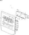
- Figure 2 – is a schematic partially exploded perspective view of the drawer assembly of Fig. 1, wherein the two decorative members are assembled with each other;
- Figure 3 – is a schematic perspective view of the drawer assembly of Fig. 1, prior to assembling the main body with the decorative members and the cover member;
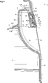
- Figure 4 – is a schematic enlarged vertical sectional view of the drawer assembly of Fig. 1, taken along the line A-A.
- the drawer assembly (1) is suitable for use in a laundry machine, in particular a laundry dryer or a laundry washer-dr y er (not shown).
- the drawer assembly (1) comprises a main body (2) which includes a first grip depression (2a) that is formed into the front surface (2b) of the main body (2) and an aperture (2c) which is formed into the main body (2).
- the first grip depression (2a) surrounds the aperture (2c) (Fig. 1 to 4).
- the drawer assembly (1) of the present invention further comprises a cover member (3), a first detachable connection (4) which detachably connects the cover member (3) to the main body (2) so as to close the aperture (2c) and a second grip depression (3a) which is formed into the front surface (3b) of the cover member (3).
- the second grip depression (3a) is flush with the first grip depression (2a).
- the first grip depression (2a) and the second grip depression (3a) have a shape that matches the upwardly bending fingers of an average adult person (not shown).
- the drawer assembly (1) further comprises a first decorative member (5); and a second detachable connection (6) which detachably connects the first decorative member (5) to the main body (2) at a position within the first grip depression (2a).
- the front surface (5a) of the first decorative member (5) is flush with the front surface (2b) of the main body (2).
- the cover member (3) immediately conceals the second detachable connection (6).
- the second detachable connection (6) is further adapted to form-fittingly connect the first decorative member (5) to the main body (2) without screwing and without welding.
- the second detachable connection (6) includes a plurality of claws (5b, 5c) and a plurality of counterpart indents (2e).
- the second detachable connection (6) is further adapted to form-fittingly connect or disconnect the first decorative member (5) respectively to or from the main body (2) when the first decorative member (5) is moved upwards or downwards relative to the main body (2).
- the drawer assembly (1) further comprises a second decorative member (7) and a third detachable connection (8) which detachably connects the second decorative member (7) to the first decorative member (5) at a position within the first grip depression (2a).
- the front surface (7a) of the second decorative member (7) is flush with the front surface (5a) of the first decorative member (5).
- the cover member (3) immediately conceals also the third detachable connection (8).
- the third detachable connection (8) is further adapted to form-fittingly connect the second decorative member (7) to the first decorative member (5) without screwing and without welding.
- the third detachable connection (8) includes a plurality of claws (5c) and a plurality of counterpart indents (7b).
- the cover member (3) comprises a first retaining section (3c) which is adapted to hold the second detachable connection (6) fixed.
- the first retaining section (3c) is provided as an abutment which presses the plurality of claws (5b, 5c) onto the plurality of indents (2e) respectively.
- the cover member (3) comprises a second retaining section (3d) which is adapted to hold the third detachable connection (8) fixed.
- the second retaining section (3d) is also provided as an abutment which presses the plurality of claws (5c) onto the plurality of indents (7b) respectively.
- the first detachable connection (4) is further adapted to form-fittingly connect the cover member (3) to the main body (2) without screwing and without welding.
- the first detachable connection (4) includes a plurality of claws (2f, 3f, 3h) and a plurality of counterpart indents (3g, 2g, 2h).
- the first detachable connection (4) is disposed onto the rear surfaces (3e, 2d) of the cover member (3) and the main body (2).
- first decorative member (5) and the second decorative member (7) each has a rectangular outline.
- first decorative member (5) and the second decorative member (7) each has the same width which is equal to the width of each of the grip depressions (2a, 3a).
- first decorative member (5) and the second decorative member (7) are arranged side by side in the vertical direction and located within the uppermost section of the first grip depression (2a) and in front of the cover member (3).
- the main body (2), the cover member (3), and the decorative members (5, 7) are each provided as a single piece.
- the drawer assembly includes (1) said four single pieces.
- the main body (2), the cover member (3), and the decorative members (5, 7) are assembled by means of the first to third detachable connections (4, 6, 8) without screwing and without welding.
- the laundry machine is provided as a laundry dryer (not shown).
- laundry dryer comprises a condensate container (not shown) for collecting the condensate extracted from the laundry; and a slot (not shown) for releasably receiving the condensate container.
- the condensate container is extendably disposed into the slot.
- the drawer assembly (1) is connected to the condensate container.
- the laundry machine is provided as a laundry washer-dryer (not shown).
- the laundry washer-dryer comprises a detergent container (not shown) for the replenishment of the detergent and a slot (not shown) for releasably receiving the detergent container.
- the detergent container is extendably disposed into the slot.
- the drawer assembly (1) is connected to the detergent container.
- a major advantageous effect of the present invention is that the tactile feeling of the drawer assembly (1) has been improved by virtue of the ergonomic grip depressions (2a, 3a) which are mutually flush with each other.
- the fingers of the user are prevented from contacting any sharp edges, and thus the safety of the drawer assembly (1) has been improved. Thereby, the user can manipulate the detergent/condensate container more securely.
- the cover member (3) can be detachably connected to the main body (2) without the need of welding or adhesive bonding. Thereby, the assemblage can be performed in an environment friendly way.
- Another major advantageous effect of the present invention is that the cover member (3) and the main body (2) of the drawer assembly (1) can be manufactured from different materials.
- drawer assembly (1) can be provided in a cost-effective way without compromising the tactile feeling of the grip depressions (2a, 3a).
- the main body (2) can be produced from a high-quality material with an improved appearance whereas the cover member (3) can be produced from a comparatively less expensive material.
- the valuable resources can be saved.
- Other advantageous effects of the present invention can be taken from the above described particular embodiments.
Landscapes
- Engineering & Computer Science (AREA)
- Textile Engineering (AREA)
- Drawers Of Furniture (AREA)
Abstract
The present invention relates to a drawer assembly (1) for use in a laundry machine comprising a main body (2) which includes: a first grip depression (2a) that is formed into the front surface (2b) of the main body (2) and an aperture (2c) which is formed into the main body (2). The first grip depression (2a) surrounds the aperture (2c). The drawer assembly (1) of the present invention further comprises: a cover member (3); a first detachable connection (4) which detachably connects the cover member (3) to the main body (2) so as to close the aperture (2c) and a second grip depression (3a) which is formed into the front surface (3b) of the cover member (3).
Description
The present invention relates to a laundry machine in particular to a laundry dryer or a laundry washer-dryer. The present invention more particularly relates to the drawer for the condensate container or the detergent container in a laundry machine.
Laundry machines such as laundry dryers or laundry washer-dryers are commonly known in the art. A laundry dryer is commonly provided with a condensate container for collecting the condensate which has been extracted from the laundry. This condensate container is generally extendably disposed into a slot of the appliance, and can be released by the user for evacuation. The condensate container is generally provided with a drawer which allows the user to manipulate the same. A laundry washer is commonly provided with a detergent container for replenishing the detergent. The detergent container is generally extendably disposed into a slot of the appliance, and can be pulled out by the user for replenishment. The detergent container is generally provided with a drawer which allows the user to manipulate the same.
The drawer of a laundry machine generally comprises a main body which includes a grip depression that is formed into the front surface thereof. The grip depression generally surrounds an aperture which is formed into the main body. And the main body is connected to the condensate container or the detergent container. The user inserts his/her fingers into the grip depression through the aperture, grips the rear surface of the main body, and pulls out the condensate/detergent container.
WO2010076180 (A1) discloses a condenser type laundry dryer.
A problem with the prior art laundry machines is that the drawer has an uncomfortable tactile feeling since there is generally a risk that the user unintentionally brings his/her fingers in contact with the sharp edges of the grip depression when manipulating the condensate/detergent container or when removing any dirt from the drawer. The customer satisfaction easily decreases because of the inferior quality and the complaints increase.
An objective of the present invention is to provide a drawer assembly for use in a laundry machine which overcomes the aforementioned problems of the prior art in a cost effective way and which has an improved tactile feeling, an improved safety and usability, and an improved assemblage.
This objective has been achieved by the drawer assembly as defined in claim 1, and the laundry machine as defined in claim 12. Further achievements have been attained by the subject-matters respectively defined in the dependent claims.
The drawer assembly of the present invention further comprises: a cover member; a detachable connection which detachably connects the cover member to the main body so as to close the aperture of the main body; and an additional grip depression which is formed into the front surface of the cover member. The grip depression of the cover member is flush with the grip depression of the main body. And the two grip depressions together have a shape that matches the upwardly bending fingers of an average adult person.
A major advantageous effect of the present invention is that the tactile feeling of the drawer assembly has been improved by virtue of the ergonomic grip depressions which are mutually flush with each other. When manipulating the container, the fingers of the user are prevented from contacting the aforementioned sharp edges, and thus the safety of the drawer assembly has been improved. Thereby, the user can manipulate the container more securely. Another major advantageous effect of the present invention is that the cover member can be detachably connected to the main body without the need of welding or adhesive bonding. Thereby, the assemblage can be performed in an environment friendly way. Another major advantageous effect of the present invention is that the cover member and the main body of the drawer assembly can be manufactured from different materials. Thereby, the drawer assembly can be provided in a cost-effective way without compromising the tactile feeling of the grip depressions. For instance, the main body can be produced from a high-quality material with an improved appearance whereas the cover member can be produced from a comparatively less expensive material. Thereby, the valuable resources can be saved.
In an embodiment, the drawer assembly has a decorative member which can be detachably connected to the main body at a position within the grip depression of the main body such that its front surface becomes flush with the front surface of the main body. In this embodiment, the cover member immediately conceals the detachable connection between the decorative member and the main body. This embodiment is particularly advantageous as the fingers of the user are prevented from contacting the detachable connection when manipulating the container. Thereby, the tactile feeling of the drawer assembly has been further improved and thus, the user can manipulate the container more securely and ergonomically. This embodiment is also particularly advantageous as the decorative member can be manufactured from a different material which has a comparatively higher quality. Moreover, the decorative member can also be varied in size and shape, and thus the production of the drawer assembly is rendered more flexible.
In another embodiment, the detachable connection between the decorative member and the main body is provided as a form-fitting connection. This embodiment is particularly advantageous the decorative member can be protected during the assemblage from excessive mechanical stresses, permanent deformations and dislocations. Thereby, also a delicate and small decorative member can be smoothly connected to the main body.
In another embodiment, the drawer assembly has an additional decorative member which can be detachably connected to the other decorative member at a position within the grip depression of the main body such that front surfaces of the decorative members become mutually flush. In this embodiment, the cover member immediately conceals also the detachable connection between the decorative members. This embodiment is particularly advantageous as the two decorative members can be assembled with each other prior to connecting to the main body.
In another embodiment, the detachable connection between the two decorative members is provided as a form-fitting connection. This embodiment is particularly advantageous as the decorative members can be prevented during the assemblage from excessive mechanical stresses, permanent deformations and relative dislocations. Thereby, delicate and narrow sized decorative members can be smoothly connected side by side onto the main body in a flush way.
In another embodiment, the cover member holds the detachable connections between the two decorative members as well as each detachable connection between the decorative member and the main body fixed. This embodiment is particularly advantageous as the mechanical integrity of the drawer assembly has been improved, and thus the front surfaces of the main body and the decorative members can be maintained mutually flush.
In another embodiment, the main body, the cover member, and the one or more decorative members are provided as single pieces respectively which can be assembled by means of the respective detachable connections without screwing and without welding. This embodiment is particularly advantageous as the drawer assembly can be more flexibly designed and easily assembled without compromising mechanical integrity and ergonomics thereof.
In other alternative embodiments, the laundry machine is respectively provided as a laundry dryer and a laundry washer. In these embodiments the drawer assemblies are accordingly connected to condensate containers and to the detergent container respectively for allowing the user to manipulate the same.
Additional features and additional advantageous effects of the drawer assembly and the laundry machine of the present invention will become more apparent with the detailed description of the embodiments with reference to the accompanying drawings in which:
Figure 1 – is a schematic front view of a drawer assembly according to an embodiment of the present invention;
Figure 2 – is a schematic partially exploded perspective view of the drawer assembly of Fig. 1, wherein the two decorative members are assembled with each other;
Figure 3 – is a schematic perspective view of the drawer assembly of Fig. 1, prior to assembling the main body with the decorative members and the cover member;
Figure 4 – is a schematic enlarged vertical sectional view of the drawer assembly of Fig. 1, taken along the line A-A.
The reference signs appearing on the drawings relate to the following technical features.
- Drawer assembly
- Main body
2a. 1st grip depression
2b. Front surface
2c. Aperture
2d. Rear surface
2d. Rear surface
2e Indent
2f. Claw
2g. Indent
2h. Indent
3. Cover member
3. Cover member
3a. 2nd grip depression
3b. Front surface
3c. 1st retaining section
3d. 2nd retaining section
3e. Rear surface
3f. Claw
3g. Indent
3h. Claw
4. 1st detachable connection
4. 1st detachable connection
5. 1st decorative member
5a. Front surface
5b. Claw
5c. Claw
6. 2nd detachable connection
7. 2nd decorative member
7a. Front surface
7b. Indent
8. 3rd detachable connection
The drawer assembly (1) is suitable for use in a laundry machine, in particular a laundry dryer or a laundry washer-dryer (not shown). The drawer assembly (1) comprises a main body (2) which includes a first grip depression (2a) that is formed into the front surface (2b) of the main body (2) and an aperture (2c) which is formed into the main body (2). The first grip depression (2a) surrounds the aperture (2c) (Fig. 1 to 4).
The drawer assembly (1) of the present invention further comprises a cover member (3), a first detachable connection (4) which detachably connects the cover member (3) to the main body (2) so as to close the aperture (2c) and a second grip depression (3a) which is formed into the front surface (3b) of the cover member (3). The second grip depression (3a) is flush with the first grip depression (2a). And the first grip depression (2a) and the second grip depression (3a) have a shape that matches the upwardly bending fingers of an average adult person (not shown).
In an embodiment, the drawer assembly (1) further comprises a first decorative member (5); and a second detachable connection (6) which detachably connects the first decorative member (5) to the main body (2) at a position within the first grip depression (2a). In this embodiment, the front surface (5a) of the first decorative member (5) is flush with the front surface (2b) of the main body (2). In addition, the cover member (3) immediately conceals the second detachable connection (6).
In another embodiment, the second detachable connection (6) is further adapted to form-fittingly connect the first decorative member (5) to the main body (2) without screwing and without welding.
In another embodiment, the second detachable connection (6) includes a plurality of claws (5b, 5c) and a plurality of counterpart indents (2e).
In another embodiment, the second detachable connection (6) is further adapted to form-fittingly connect or disconnect the first decorative member (5) respectively to or from the main body (2) when the first decorative member (5) is moved upwards or downwards relative to the main body (2).
In another embodiment, the drawer assembly (1) further comprises a second decorative member (7) and a third detachable connection (8) which detachably connects the second decorative member (7) to the first decorative member (5) at a position within the first grip depression (2a). In this embodiment, the front surface (7a) of the second decorative member (7) is flush with the front surface (5a) of the first decorative member (5). In addition, the cover member (3) immediately conceals also the third detachable connection (8).
In another embodiment, the third detachable connection (8) is further adapted to form-fittingly connect the second decorative member (7) to the first decorative member (5) without screwing and without welding.
In another embodiment, the third detachable connection (8) includes a plurality of claws (5c) and a plurality of counterpart indents (7b).
In another embodiment, the cover member (3) comprises a first retaining section (3c) which is adapted to hold the second detachable connection (6) fixed.
In another embodiment, the first retaining section (3c) is provided as an abutment which presses the plurality of claws (5b, 5c) onto the plurality of indents (2e) respectively.
In another embodiment, the cover member (3) comprises a second retaining section (3d) which is adapted to hold the third detachable connection (8) fixed.
In another embodiment, the second retaining section (3d) is also provided as an abutment which presses the plurality of claws (5c) onto the plurality of indents (7b) respectively.
In another embodiment, the first detachable connection (4) is further adapted to form-fittingly connect the cover member (3) to the main body (2) without screwing and without welding.
In another embodiment, the first detachable connection (4) includes a plurality of claws (2f, 3f, 3h) and a plurality of counterpart indents (3g, 2g, 2h).
In another embodiment, the first detachable connection (4) is disposed onto the rear surfaces (3e, 2d) of the cover member (3) and the main body (2).
In another embodiment, the first decorative member (5) and the second decorative member (7) each has a rectangular outline. In this embodiment, the first decorative member (5) and the second decorative member (7) each has the same width which is equal to the width of each of the grip depressions (2a, 3a). In addition, the first decorative member (5) and the second decorative member (7) are arranged side by side in the vertical direction and located within the uppermost section of the first grip depression (2a) and in front of the cover member (3).
In another embodiment, the main body (2), the cover member (3), and the decorative members (5, 7) are each provided as a single piece. In this embodiment, the drawer assembly includes (1) said four single pieces. In this embodiment, the main body (2), the cover member (3), and the decorative members (5, 7) are assembled by means of the first to third detachable connections (4, 6, 8) without screwing and without welding.
In another embodiment, the laundry machine is provided as a laundry dryer (not shown). In this embodiment, laundry dryer comprises a condensate container (not shown) for collecting the condensate extracted from the laundry; and a slot (not shown) for releasably receiving the condensate container. In this embodiment, the condensate container is extendably disposed into the slot. In addition, the drawer assembly (1) is connected to the condensate container.
In another alternative embodiment, the laundry machine is provided as a laundry washer-dryer (not shown). The laundry washer-dryer comprises a detergent container (not shown) for the replenishment of the detergent and a slot (not shown) for releasably receiving the detergent container. In this embodiment, the detergent container is extendably disposed into the slot. In addition, the drawer assembly (1) is connected to the detergent container.
A major advantageous effect of the present invention is that the tactile feeling of the drawer assembly (1) has been improved by virtue of the ergonomic grip depressions (2a, 3a) which are mutually flush with each other. When manipulating the detergent/condensate container, the fingers of the user are prevented from contacting any sharp edges, and thus the safety of the drawer assembly (1) has been improved. Thereby, the user can manipulate the detergent/condensate container more securely. Another major advantageous effect of the present invention is that the cover member (3) can be detachably connected to the main body (2) without the need of welding or adhesive bonding. Thereby, the assemblage can be performed in an environment friendly way. Another major advantageous effect of the present invention is that the cover member (3) and the main body (2) of the drawer assembly (1) can be manufactured from different materials. Thereby, drawer assembly (1) can be provided in a cost-effective way without compromising the tactile feeling of the grip depressions (2a, 3a). For instance, the main body (2) can be produced from a high-quality material with an improved appearance whereas the cover member (3) can be produced from a comparatively less expensive material. Thereby, the valuable resources can be saved. Other advantageous effects of the present invention can be taken from the above described particular embodiments.
Claims (14)
- A drawer assembly (1) for use in a laundry machine, the drawer assembly (1) comprising a main body (2) which includes a first grip depression (2a) that is formed into the front surface (2b) of the main body (2); and an aperture (2c) which is formed into the main body (2), wherein the first grip depression (2a) surrounds the aperture (2c), the drawer assembly (1) being characterized in that a cover member (3), a first detachable connection (4) which detachably connects the cover member (3) to the main body (2) so as to close the aperture (2c), and a second grip depression (3a) which is formed into the front surface (3b) of the cover member (3), wherein the second grip depression (3a) is flush with the first grip depression (2a), and wherein the first grip depression (2a) and the second grip depression (3a) have a shape that matches the upwardly bending fingers of an average adult person.
- The drawer assembly (1) according to claim 1, characterized in that a first decorative member (5); and a second detachable connection (6) which detachably connects the first decorative member (5) to the main body (2) at a position within the first grip depression (2a), wherein the front surface (5a) of the first decorative member (5) is flush with the front surface (2b) of the main body (2), and wherein the cover member (3) immediately conceals the second detachable connection (6).
- The drawer assembly (1) according to claim 2, characterized in that the second detachable connection (6) is further adapted to form-fittingly connect the first decorative member (5) to the main body (2) without screwing and without welding.
- The drawer assembly (1) according to claim 3, characterized in that the second detachable connection (6) is further adapted to form-fittingly connect or disconnect the first decorative member (5) respectively to or from the main body (2) when the first decorative member (5) is moved upwards or downwards relative to the main body (2) respectively.
- The drawer assembly (1) according to any one of claims 2 to 4, characterized in that a second decorative member (7); and a third detachable connection (8) which detachably connects the second decorative member (7) to the first decorative member (5) at a position within the first grip depression (2a), wherein the front surface (7a) of the second decorative member (7) is flush with the front surface (5a) of the first decorative member (5), and wherein the cover member (3) immediately conceals the third detachable connection (8).
- The drawer assembly (1) according to claim 5, characterized in that the third detachable connection (8) is further adapted to form-fittingly connect the second decorative member (7) to the first decorative member (5) without screwing and without welding.
- The drawer assembly (1) according to claim 6, characterized in that the cover member (3) comprises a first retaining section (3c) which is adapted to hold the second detachable connection (6) fixed.
- The drawer assembly (1) according to claims 6 or 7, characterized in that the cover member (3) comprises a second retaining section (3d) which is adapted to hold the third detachable connection (8) fixed.
- The drawer assembly (1) according to any one of claim 1, characterized in that the first detachable connection (4) is further adapted to form-fittingly connect the cover member (3) to the main body (2) without screwing and without welding.
- The drawer assembly (1) according to any one of claim 1, characterized in that the first detachable connection (4) is disposed onto the rear surfaces (3e, 2d) of the cover member (3) and the main body (2).
- The drawer assembly (1) according to claim 1, characterized in that the first decorative member (5) and the second decorative member (7) each has a rectangular outline, wherein the first decorative member (5) and the second decorative member (7) each has the same width which is equal to the width of each of the grip depressions (2a;3a), and wherein the first decorative member (5) and the second decorative member (7) are arranged side by side in the vertical direction and located within the uppermost section of the first grip depression (2a) and in front of the cover member (3).
- A laundry machine, in particular a laundry dryer or a laundry washer-dryer, characterized in that the drawer assembly (1) as defined in claim 1.
- The laundry machine according to claim 12, characterized in that the laundry machine is provided as a laundry dryer and comprises a condensate container for collecting the condensate extracted from the laundry and a slot for releasably receiving the condensate container, wherein the condensate container is extendably disposed into the slot, and wherein the drawer assembly (1) is connected to the condensate container.
- The laundry machine according to claim 12, characterized in that the laundry machine is provided as a laundry washer-dryer and comprises a detergent container for the replenishment of the detergent and a slot for releasably receiving the detergent container, wherein the detergent container is extendably disposed into the slot, and wherein the drawer assembly (1) is connected to the detergent container.
Priority Applications (1)
| Application Number | Priority Date | Filing Date | Title |
|---|---|---|---|
| PCT/EP2015/073214 WO2017059907A1 (en) | 2015-10-08 | 2015-10-08 | Drawer assembly for a laundry machine |
Applications Claiming Priority (1)
| Application Number | Priority Date | Filing Date | Title |
|---|---|---|---|
| PCT/EP2015/073214 WO2017059907A1 (en) | 2015-10-08 | 2015-10-08 | Drawer assembly for a laundry machine |
Publications (1)
| Publication Number | Publication Date |
|---|---|
| WO2017059907A1 true WO2017059907A1 (en) | 2017-04-13 |
Family
ID=54252320
Family Applications (1)
| Application Number | Title | Priority Date | Filing Date |
|---|---|---|---|
| PCT/EP2015/073214 Ceased WO2017059907A1 (en) | 2015-10-08 | 2015-10-08 | Drawer assembly for a laundry machine |
Country Status (1)
| Country | Link |
|---|---|
| WO (1) | WO2017059907A1 (en) |
Cited By (8)
| Publication number | Priority date | Publication date | Assignee | Title |
|---|---|---|---|---|
| CN109898923A (en) * | 2017-12-11 | 2019-06-18 | 青岛海尔智慧厨房电器有限公司 | Handle structure |
| CN109893003A (en) * | 2017-12-11 | 2019-06-18 | 青岛海尔智慧厨房电器有限公司 | Handle structure |
| EP3511464A1 (en) * | 2018-01-15 | 2019-07-17 | Wuxi Little Swan Co., Ltd. | Washing machine and components therefor |
| WO2019192881A1 (en) * | 2018-04-02 | 2019-10-10 | Arcelik Anonim Sirketi | A washing machine comprising a detergent drawer |
| CN112301672A (en) * | 2019-07-30 | 2021-02-02 | 东芝生活电器株式会社 | Washing machine and treatment agent container |
| EP4091784A1 (en) * | 2021-05-14 | 2022-11-23 | BSH Hausgeräte GmbH | Clothes treating device including drawer panel |
| CN118727386A (en) * | 2023-03-31 | 2024-10-01 | 重庆海尔滚筒洗衣机有限公司 | Additive delivery device |
| EP4502265A1 (en) * | 2023-08-01 | 2025-02-05 | BSH Hausgeräte GmbH | Panel component and household appliance |
Citations (13)
| Publication number | Priority date | Publication date | Assignee | Title |
|---|---|---|---|---|
| AU454752B2 (en) * | 1970-08-12 | 1974-10-21 | john WILLIAM LEICHHARDT | Combination drawer handle and cardholder |
| DE3213420A1 (en) * | 1982-04-10 | 1983-10-13 | Wilhelm Dr.-Ing. 5340 Bad Honnef Lepper | Washing machine, washer/drier and laundry drier with stand |
| DE4304484A1 (en) * | 1993-02-15 | 1994-08-18 | Bosch Siemens Hausgeraete | Containers, in particular drawer-like containers |
| EP0678258A1 (en) * | 1994-03-22 | 1995-10-25 | Société des BAGAGES HENRY PIERRE | Handle, especially label holder, for panels and panel, especially drawer front panel, being equipped therewith |
| EP0744142A1 (en) * | 1995-05-22 | 1996-11-27 | Ronda Europa S.P.A. | Handle, particularly for industrial and/or commercial furniture |
| DE102005011046B3 (en) * | 2005-03-08 | 2006-05-04 | Miele & Cie. Kg | Drawer container for flushing detergent into washing machine or collecting condensate from dryer, has fastening arrangement including hooks and pockets with play when engaged |
| CN1779044A (en) * | 2004-11-17 | 2006-05-31 | 乐金电子(天津)电器有限公司 | Detergent supplier of washer |
| DE102005021588A1 (en) * | 2005-05-10 | 2006-11-16 | BSH Bosch und Siemens Hausgeräte GmbH | refrigerated goods |
| US20090145175A1 (en) * | 2007-11-21 | 2009-06-11 | Lg Electronics Inc. | Washing machine |
| DE102008055029A1 (en) * | 2008-12-19 | 2010-07-01 | BSH Bosch und Siemens Hausgeräte GmbH | Household appliance, in particular dishwasher |
| WO2010076180A1 (en) | 2008-12-30 | 2010-07-08 | Arcelik Anonim Sirketi | Condenser type laundry dryer |
| US20100201236A1 (en) * | 2007-09-03 | 2010-08-12 | Kim Hyun-Seok | Supporter and pedestal and washing/drying machine having the same |
| US20140145572A1 (en) * | 2012-11-27 | 2014-05-29 | Whirlpool Corporation | Dishwasher support structures to reduce rotation of a door crown |
-
2015
- 2015-10-08 WO PCT/EP2015/073214 patent/WO2017059907A1/en not_active Ceased
Patent Citations (13)
| Publication number | Priority date | Publication date | Assignee | Title |
|---|---|---|---|---|
| AU454752B2 (en) * | 1970-08-12 | 1974-10-21 | john WILLIAM LEICHHARDT | Combination drawer handle and cardholder |
| DE3213420A1 (en) * | 1982-04-10 | 1983-10-13 | Wilhelm Dr.-Ing. 5340 Bad Honnef Lepper | Washing machine, washer/drier and laundry drier with stand |
| DE4304484A1 (en) * | 1993-02-15 | 1994-08-18 | Bosch Siemens Hausgeraete | Containers, in particular drawer-like containers |
| EP0678258A1 (en) * | 1994-03-22 | 1995-10-25 | Société des BAGAGES HENRY PIERRE | Handle, especially label holder, for panels and panel, especially drawer front panel, being equipped therewith |
| EP0744142A1 (en) * | 1995-05-22 | 1996-11-27 | Ronda Europa S.P.A. | Handle, particularly for industrial and/or commercial furniture |
| CN1779044A (en) * | 2004-11-17 | 2006-05-31 | 乐金电子(天津)电器有限公司 | Detergent supplier of washer |
| DE102005011046B3 (en) * | 2005-03-08 | 2006-05-04 | Miele & Cie. Kg | Drawer container for flushing detergent into washing machine or collecting condensate from dryer, has fastening arrangement including hooks and pockets with play when engaged |
| DE102005021588A1 (en) * | 2005-05-10 | 2006-11-16 | BSH Bosch und Siemens Hausgeräte GmbH | refrigerated goods |
| US20100201236A1 (en) * | 2007-09-03 | 2010-08-12 | Kim Hyun-Seok | Supporter and pedestal and washing/drying machine having the same |
| US20090145175A1 (en) * | 2007-11-21 | 2009-06-11 | Lg Electronics Inc. | Washing machine |
| DE102008055029A1 (en) * | 2008-12-19 | 2010-07-01 | BSH Bosch und Siemens Hausgeräte GmbH | Household appliance, in particular dishwasher |
| WO2010076180A1 (en) | 2008-12-30 | 2010-07-08 | Arcelik Anonim Sirketi | Condenser type laundry dryer |
| US20140145572A1 (en) * | 2012-11-27 | 2014-05-29 | Whirlpool Corporation | Dishwasher support structures to reduce rotation of a door crown |
Cited By (9)
| Publication number | Priority date | Publication date | Assignee | Title |
|---|---|---|---|---|
| CN109898923A (en) * | 2017-12-11 | 2019-06-18 | 青岛海尔智慧厨房电器有限公司 | Handle structure |
| CN109893003A (en) * | 2017-12-11 | 2019-06-18 | 青岛海尔智慧厨房电器有限公司 | Handle structure |
| CN109893003B (en) * | 2017-12-11 | 2024-07-02 | 青岛海尔智慧厨房电器有限公司 | Handle structure |
| EP3511464A1 (en) * | 2018-01-15 | 2019-07-17 | Wuxi Little Swan Co., Ltd. | Washing machine and components therefor |
| WO2019192881A1 (en) * | 2018-04-02 | 2019-10-10 | Arcelik Anonim Sirketi | A washing machine comprising a detergent drawer |
| CN112301672A (en) * | 2019-07-30 | 2021-02-02 | 东芝生活电器株式会社 | Washing machine and treatment agent container |
| EP4091784A1 (en) * | 2021-05-14 | 2022-11-23 | BSH Hausgeräte GmbH | Clothes treating device including drawer panel |
| CN118727386A (en) * | 2023-03-31 | 2024-10-01 | 重庆海尔滚筒洗衣机有限公司 | Additive delivery device |
| EP4502265A1 (en) * | 2023-08-01 | 2025-02-05 | BSH Hausgeräte GmbH | Panel component and household appliance |
Similar Documents
| Publication | Publication Date | Title |
|---|---|---|
| USD851845S1 (en) | Washing machine | |
| USD963267S1 (en) | Electronic washing and drying machine for laundry purpose | |
| USD633261S1 (en) | Washing machine | |
| USD902741S1 (en) | Laundry detergent capsule | |
| USD911185S1 (en) | Single-dose laundry detergent unit | |
| USD621116S1 (en) | Soleplate for laundry iron | |
| USD902740S1 (en) | Laundry detergent capsule | |
| USD938670S1 (en) | Shell for washing machine | |
| USD527499S1 (en) | Washing machine | |
| USD958471S1 (en) | Electronic washing and drying machine for laundry purpose | |
| USD954366S1 (en) | Electronic washing and drying machine for laundry purpose | |
| USD959767S1 (en) | Electronic washing and drying machine for laundry purpose | |
| USD1010962S1 (en) | Washing machine with clothes dryer | |
| USD958473S1 (en) | Electronic washing and drying machine for laundry purpose | |
| USD959768S1 (en) | Electronic washing and drying machine for laundry purpose | |
| USD994491S1 (en) | Combined laundry detergent and fabric softener dispenser | |
| USD935120S1 (en) | Washing machine agitator | |
| USD961178S1 (en) | Laundry basket | |
| USD855917S1 (en) | Laundry Basket | |
| USD957074S1 (en) | Electronic washing and drying machine for laundry purpose | |
| USD957071S1 (en) | Electronic washing and drying machine for laundry purpose | |
| USD957072S1 (en) | Electronic washing and drying machine for laundry purpose | |
| USD959766S1 (en) | Electronic washing and drying machine for laundry purpose | |
| USD1028392S1 (en) | Electric washing and drying machine for laundry purpose | |
| USD894508S1 (en) | Detergent dispenser for washing machine |
Legal Events
| Date | Code | Title | Description |
|---|---|---|---|
| 121 | Ep: the epo has been informed by wipo that ep was designated in this application |
Ref document number: 15775230 Country of ref document: EP Kind code of ref document: A1 |
|
| NENP | Non-entry into the national phase |
Ref country code: DE |
|
| 122 | Ep: pct application non-entry in european phase |
Ref document number: 15775230 Country of ref document: EP Kind code of ref document: A1 |