WO2017057699A1 - Device for continuously producing chemically-modified cellulose and method used in same - Google Patents
Device for continuously producing chemically-modified cellulose and method used in same Download PDFInfo
- Publication number
- WO2017057699A1 WO2017057699A1 PCT/JP2016/079072 JP2016079072W WO2017057699A1 WO 2017057699 A1 WO2017057699 A1 WO 2017057699A1 JP 2016079072 W JP2016079072 W JP 2016079072W WO 2017057699 A1 WO2017057699 A1 WO 2017057699A1
- Authority
- WO
- WIPO (PCT)
- Prior art keywords
- cellulose
- extruder
- chemically modified
- modified cellulose
- raw material
- Prior art date
Links
Images


Classifications
-
- C—CHEMISTRY; METALLURGY
- C08—ORGANIC MACROMOLECULAR COMPOUNDS; THEIR PREPARATION OR CHEMICAL WORKING-UP; COMPOSITIONS BASED THEREON
- C08B—POLYSACCHARIDES; DERIVATIVES THEREOF
- C08B17/00—Apparatus for esterification or etherification of cellulose
- C08B17/02—Apparatus for esterification or etherification of cellulose for making organic esters of cellulose
-
- B—PERFORMING OPERATIONS; TRANSPORTING
- B01—PHYSICAL OR CHEMICAL PROCESSES OR APPARATUS IN GENERAL
- B01F—MIXING, e.g. DISSOLVING, EMULSIFYING OR DISPERSING
- B01F27/00—Mixers with rotary stirring devices in fixed receptacles; Kneaders
- B01F27/05—Stirrers
- B01F27/11—Stirrers characterised by the configuration of the stirrers
- B01F27/114—Helically shaped stirrers, i.e. stirrers comprising a helically shaped band or helically shaped band sections
- B01F27/1143—Helically shaped stirrers, i.e. stirrers comprising a helically shaped band or helically shaped band sections screw-shaped, e.g. worms
-
- B—PERFORMING OPERATIONS; TRANSPORTING
- B01—PHYSICAL OR CHEMICAL PROCESSES OR APPARATUS IN GENERAL
- B01F—MIXING, e.g. DISSOLVING, EMULSIFYING OR DISPERSING
- B01F35/00—Accessories for mixers; Auxiliary operations or auxiliary devices; Parts or details of general application
- B01F35/181—Preventing generation of dust or dirt; Sieves; Filters
- B01F35/189—Venting, degassing or ventilating of gases, fumes or toxic vapours during mixing
-
- B—PERFORMING OPERATIONS; TRANSPORTING
- B01—PHYSICAL OR CHEMICAL PROCESSES OR APPARATUS IN GENERAL
- B01F—MIXING, e.g. DISSOLVING, EMULSIFYING OR DISPERSING
- B01F35/00—Accessories for mixers; Auxiliary operations or auxiliary devices; Parts or details of general application
- B01F35/71—Feed mechanisms
- B01F35/717—Feed mechanisms characterised by the means for feeding the components to the mixer
- B01F35/7173—Feed mechanisms characterised by the means for feeding the components to the mixer using gravity, e.g. from a hopper
- B01F35/71731—Feed mechanisms characterised by the means for feeding the components to the mixer using gravity, e.g. from a hopper using a hopper
-
- B—PERFORMING OPERATIONS; TRANSPORTING
- B01—PHYSICAL OR CHEMICAL PROCESSES OR APPARATUS IN GENERAL
- B01J—CHEMICAL OR PHYSICAL PROCESSES, e.g. CATALYSIS OR COLLOID CHEMISTRY; THEIR RELEVANT APPARATUS
- B01J19/00—Chemical, physical or physico-chemical processes in general; Their relevant apparatus
- B01J19/18—Stationary reactors having moving elements inside
- B01J19/20—Stationary reactors having moving elements inside in the form of helices, e.g. screw reactors
-
- B—PERFORMING OPERATIONS; TRANSPORTING
- B29—WORKING OF PLASTICS; WORKING OF SUBSTANCES IN A PLASTIC STATE IN GENERAL
- B29C—SHAPING OR JOINING OF PLASTICS; SHAPING OF MATERIAL IN A PLASTIC STATE, NOT OTHERWISE PROVIDED FOR; AFTER-TREATMENT OF THE SHAPED PRODUCTS, e.g. REPAIRING
- B29C48/00—Extrusion moulding, i.e. expressing the moulding material through a die or nozzle which imparts the desired form; Apparatus therefor
- B29C48/03—Extrusion moulding, i.e. expressing the moulding material through a die or nozzle which imparts the desired form; Apparatus therefor characterised by the shape of the extruded material at extrusion
-
- C—CHEMISTRY; METALLURGY
- C08—ORGANIC MACROMOLECULAR COMPOUNDS; THEIR PREPARATION OR CHEMICAL WORKING-UP; COMPOSITIONS BASED THEREON
- C08B—POLYSACCHARIDES; DERIVATIVES THEREOF
- C08B3/00—Preparation of cellulose esters of organic acids
- C08B3/12—Preparation of cellulose esters of organic acids of polybasic organic acids
-
- C—CHEMISTRY; METALLURGY
- C08—ORGANIC MACROMOLECULAR COMPOUNDS; THEIR PREPARATION OR CHEMICAL WORKING-UP; COMPOSITIONS BASED THEREON
- C08B—POLYSACCHARIDES; DERIVATIVES THEREOF
- C08B3/00—Preparation of cellulose esters of organic acids
- C08B3/16—Preparation of mixed organic cellulose esters, e.g. cellulose aceto-formate or cellulose aceto-propionate
-
- H—ELECTRICITY
- H01—ELECTRIC ELEMENTS
- H01M—PROCESSES OR MEANS, e.g. BATTERIES, FOR THE DIRECT CONVERSION OF CHEMICAL ENERGY INTO ELECTRICAL ENERGY
- H01M50/00—Constructional details or processes of manufacture of the non-active parts of electrochemical cells other than fuel cells, e.g. hybrid cells
- H01M50/40—Separators; Membranes; Diaphragms; Spacing elements inside cells
- H01M50/409—Separators, membranes or diaphragms characterised by the material
- H01M50/411—Organic material
- H01M50/429—Natural polymers
- H01M50/4295—Natural cotton, cellulose or wood
-
- H—ELECTRICITY
- H01—ELECTRIC ELEMENTS
- H01M—PROCESSES OR MEANS, e.g. BATTERIES, FOR THE DIRECT CONVERSION OF CHEMICAL ENERGY INTO ELECTRICAL ENERGY
- H01M50/00—Constructional details or processes of manufacture of the non-active parts of electrochemical cells other than fuel cells, e.g. hybrid cells
- H01M50/40—Separators; Membranes; Diaphragms; Spacing elements inside cells
- H01M50/409—Separators, membranes or diaphragms characterised by the material
- H01M50/44—Fibrous material
-
- H—ELECTRICITY
- H01—ELECTRIC ELEMENTS
- H01M—PROCESSES OR MEANS, e.g. BATTERIES, FOR THE DIRECT CONVERSION OF CHEMICAL ENERGY INTO ELECTRICAL ENERGY
- H01M50/00—Constructional details or processes of manufacture of the non-active parts of electrochemical cells other than fuel cells, e.g. hybrid cells
- H01M50/40—Separators; Membranes; Diaphragms; Spacing elements inside cells
- H01M50/409—Separators, membranes or diaphragms characterised by the material
- H01M50/443—Particulate material
-
- B—PERFORMING OPERATIONS; TRANSPORTING
- B29—WORKING OF PLASTICS; WORKING OF SUBSTANCES IN A PLASTIC STATE IN GENERAL
- B29K—INDEXING SCHEME ASSOCIATED WITH SUBCLASSES B29B, B29C OR B29D, RELATING TO MOULDING MATERIALS OR TO MATERIALS FOR MOULDS, REINFORCEMENTS, FILLERS OR PREFORMED PARTS, e.g. INSERTS
- B29K2001/00—Use of cellulose, modified cellulose or cellulose derivatives, e.g. viscose, as moulding material
- B29K2001/08—Cellulose derivatives
-
- B—PERFORMING OPERATIONS; TRANSPORTING
- B82—NANOTECHNOLOGY
- B82Y—SPECIFIC USES OR APPLICATIONS OF NANOSTRUCTURES; MEASUREMENT OR ANALYSIS OF NANOSTRUCTURES; MANUFACTURE OR TREATMENT OF NANOSTRUCTURES
- B82Y40/00—Manufacture or treatment of nanostructures
-
- H—ELECTRICITY
- H01—ELECTRIC ELEMENTS
- H01M—PROCESSES OR MEANS, e.g. BATTERIES, FOR THE DIRECT CONVERSION OF CHEMICAL ENERGY INTO ELECTRICAL ENERGY
- H01M50/00—Constructional details or processes of manufacture of the non-active parts of electrochemical cells other than fuel cells, e.g. hybrid cells
- H01M50/40—Separators; Membranes; Diaphragms; Spacing elements inside cells
- H01M50/489—Separators, membranes, diaphragms or spacing elements inside the cells, characterised by their physical properties, e.g. swelling degree, hydrophilicity or shut down properties
- H01M50/494—Tensile strength
-
- Y—GENERAL TAGGING OF NEW TECHNOLOGICAL DEVELOPMENTS; GENERAL TAGGING OF CROSS-SECTIONAL TECHNOLOGIES SPANNING OVER SEVERAL SECTIONS OF THE IPC; TECHNICAL SUBJECTS COVERED BY FORMER USPC CROSS-REFERENCE ART COLLECTIONS [XRACs] AND DIGESTS
- Y02—TECHNOLOGIES OR APPLICATIONS FOR MITIGATION OR ADAPTATION AGAINST CLIMATE CHANGE
- Y02E—REDUCTION OF GREENHOUSE GAS [GHG] EMISSIONS, RELATED TO ENERGY GENERATION, TRANSMISSION OR DISTRIBUTION
- Y02E60/00—Enabling technologies; Technologies with a potential or indirect contribution to GHG emissions mitigation
- Y02E60/10—Energy storage using batteries
Definitions
- the present invention relates to a chemically modified cellulose continuous production apparatus and a chemically modified cellulose continuous production method. Specifically, the present invention relates to an apparatus and a method for producing chemically modified cellulose by continuously reacting a fine powdery cellulose fiber raw material with a hydrophobic chemical substance. Furthermore, an apparatus for continuously producing a cellulose composite resin using the obtained chemically modified cellulose and its method, an apparatus for continuously producing a separator for a lithium ion battery using the cellulose composite resin, and its method It is related with the cellulose nanofiber composite separator for lithium ion batteries manufactured with the apparatus.
- fiber reinforced plastics in which fiber materials and thermoplastic resins are combined are used in various products.
- GFRP, CFRP, etc. in which glass fiber, carbon fiber, and the like are combined with a resin are widely used in fields such as automobile parts, sports goods, housing materials, and home appliances.
- a product in which these fibers are combined exhibits excellent strength characteristics.
- the plastic composite material is light in weight, excellent in strength properties, and low in environmental burden when discarded at low cost.
- Cellulosic fibers that are abundant as natural resources and have excellent strength properties are attracting attention as reinforcing fibers having these characteristics, and research is actively conducted.
- cellulose has a hydroxyl group in its molecular structure and forms hydrogen bonds within and between molecules, it has high hydrophilicity and cohesion. As a result, it is known that it is difficult to disperse in a thermoplastic resin, particularly, a highly hydrophobic olefin resin.
- cellulose refined into fibers, particularly nanofibers cellulose fibers are known to reaggregate when mixed with resin, resulting in the formation of coarse cellulose aggregates. ing.
- problems such as a decrease in strength starting from the site of the aggregate and a decrease in transparency occur. For this reason, research on the stability by improving dispersibility of cellulose in a resin and suppressing aggregation has been actively conducted.
- Patent Document 1 First, methods for combining cellulose and resin have been proposed in Patent Document 1, Patent Document 2, and the like.
- a water slurry in which defibrated cellulose is dispersed and a resin are kneaded to produce a cellulose composite pellet.
- a slurry obtained by adding a cellulose raw material in advance to nanofibers by high-pressure homogenizer treatment or the like is used. Therefore, when pellet production is performed, a deaeration process for reducing the amount of water that causes aggregation of the nanofibered cellulose is required.
- Patent Document 3 proposes a method of chemically modifying the cellulose surface in order to improve the dispersion state of cellulose in the resin and the mechanical properties of the resin.
- polybasic acid anhydride is partially esterified to a part of the hydroxyl group of cellulose, and a carboxyl group is introduced to induce a repulsive force between microfibrils. Can be maintained.
- the strength characteristics and dimensional stability are improved when combined with the resin.
- the cellulose nanofibers in this dispersion are in a microfibril state. To achieve this state, the homogenizer treatment and the starburst treatment using high-speed counter-collision are required after chemical modification, which makes the process complicated. More devices.
- a pressure kneader, a multi-screw extruder, or the like is used as a reaction apparatus, and only using a generally used flight shape, celluloses when kneading cellulose and a chemical modifier,
- a residence time of at least about 20 minutes is required to increase the reaction time.
- the cleaning operation for removing unreacted substances used for chemical modification and the drying operation are independent processes, there is a problem that they cannot be performed continuously.
- a conventional method and apparatus for combining cellulose with a chemical modification of a resin and a resin as described above are shown in the upstream process example of FIG. Although this is known to be effective as a method for chemically modifying the cellulose surface, a system and method that can continuously perform chemical modification treatment, fiber defibration, and resin complexation with a resin have not been developed. For this reason, mass production and cost reduction have not progressed, so the spread to the market is still limited.
- the present invention has been made to solve the conventional problems as described above. That is, the present invention provides an apparatus for continuously producing chemically modified cellulose obtained by reacting a finely divided cellulose fiber material with a hydrophobic chemical substance, and a method used in the apparatus. Moreover, this invention provides the apparatus used in order to manufacture a cellulose composite resin continuously from a fine powdery cellulose fiber raw material, and the method used with the apparatus. The present invention also provides a device for continuously producing a cellulose nanofiber composite separator for lithium ion batteries from a finely divided cellulose fiber raw material, and a cellulose nanofiber composite separator for lithium ion batteries produced from the device. provide.
- Extruder (4) having a hopper (5) for introducing the cellulose fiber raw material (6) and the hydrophobic chemical substance, a temperature raising mechanism, a pressure raising mechanism, a deaeration mechanism, and a screw piece for kneading )When, There is provided a chemically modified cellulose continuous production apparatus having a solvent tank (25) connected to the extruder and a drying apparatus (12) connected to the solvent tank.
- the present invention also provides:
- the finely divided cellulose fiber raw material (6) and the hydrophobic chemical substance are introduced into an extruder having a temperature raising mechanism, a pressure raising mechanism, a degassing mechanism, and a screw piece for kneading, and the hydrophobic chemical substance is introduced into the extruder.
- the present invention also provides: A first mechanism (6a) for conveying the finely divided cellulose fiber raw material (6) and the hydrophobic chemical substance; A first extruder having a hopper (5) for introducing the cellulose fiber raw material (6) and the hydrophobic chemical substance, a temperature raising mechanism, a pressure raising mechanism, a deaeration mechanism, and a screw piece for kneading.
- the present invention also provides:
- the finely divided cellulose fiber raw material (6) and the hydrophobic chemical substance are introduced into a first extruder (4) having a temperature raising mechanism, a pressure raising mechanism, a deaeration mechanism, and a screw piece for kneading, and A first step of melting a hydrophobic chemical substance, kneading the hydrophobic chemical substance and the cellulose, and further reacting them to obtain a chemically modified cellulose;
- the chemically modified cellulose is discharged from the first extruder (4) and introduced into the solvent tank (25), the chemically modified cellulose is dispersed in an organic solvent to obtain a dispersion, and then into the solvent tank (25).
- thermoplastic resin Injecting the dispersion into a drying apparatus (12) to be connected, drying the dispersion and separating it from the organic solvent, and the second step, and mixing the dried chemically modified cellulose with paraffin; Introducing a thermoplastic resin into a second extruder having a temperature raising mechanism, a pressure raising mechanism, a deaeration mechanism, and having a screw piece for kneading, and kneading these, including a third step, A method for continuously producing a cellulose composite resin is provided.
- the present invention provides Using the cellulose nanofiber composite separator continuous production apparatus for lithium ion batteries, and the cellulose nanofiber composite separator continuous production apparatus for lithium ion batteries, having a T die or a strand die connected to the cellulose composite resin continuous production apparatus A produced cellulose nanofiber composite separator for a lithium ion battery is provided.
- the present invention it is possible to continuously produce cellulose that has been chemically modified to improve the dispersion state in the thermoplastic resin, and further to remove and dry the unreacted hydrophobic compound. It is possible to carry out the process continuously and to achieve a combination of cellulose defibration and thermoplastic resin in the reactor. Further, in the present invention, the microfibril in the cellulose fiber raw material resin, which is necessary when the cellulose nanofiber composite separator for a lithium ion battery is manufactured by mixing cellulose and the resin in the cellulose fiber raw material abundant in nature. Functions that can dramatically improve the efficiency and dispersibility and stability can be added continuously.
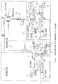
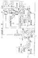
- FIG. 1 is a schematic diagram of a cellulose chemical modification / cleaning / drying / resin composite system.
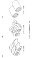
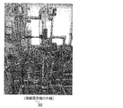
- FIG. It is a perspective view of the example of a screw for cellulose chemical modification. It is a perspective view of the example of the screw for compound of chemically modified cellulose and resin. It is a block diagram of the thin film evaporator used for drying of the cellulose which performed solvent washing
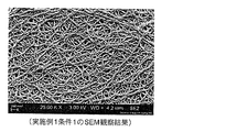
- 2 is a result of SEM observation of Example 1. It is a SEM observation result of Example 2. The analysis result of EDX of Example 1 is shown. It is a schematic diagram which shows the other form of FIG. It is explanatory drawing which shows the comparative example 1 with respect to this invention.
- the present invention makes a leap in the dispersibility and stability of cellulose fiber raw materials in thermoplastic resins, which are necessary when mixing composites of cellulose and thermoplastic resins in abundantly existing cellulose fiber raw materials.
- the present invention also provides a continuous production system for cellulose nanofiber composite separators for lithium ion batteries.
- FIG. 1 shows an outline of a system for producing cellulose chemical modification / cleaning / drying / cellulose nanofiber composite separator in the present invention.
- symbol 1 is a chemical modification process, and the hydrophobic material which hydrolyzes the cellulose raw material 6b and cellulose through the feeder 6 as the 1st mechanism 6a is provided in the hopper 5 of the screw type extruder 4.
- the surface of the cellulose molecule is chemically modified by supplying a chemical substance and kneading it with cellulose nanofibers (CeNF) while melting and kneading the chemically modified substance while being evacuated from the vacuum vent 8 using the vacuum pump 7.
- CeNF cellulose nanofibers
- a slurry (dispersion) 10 containing finely divided cellulose in a concentration of 1 to 60% by mass with respect to the dispersion is obtained. Is sent to the slurry transport pump 9.
- the slurry 10 sent from the slurry transport pump 9 is dried by a dryer 12 having a heater 11 which is a first device 12A of the drying step 2, and is passed through a weighing machine 13 by a stirrer 14 in the separator manufacturing step 3.
- the mixture is stirred together with the paraffin 17 from the paraffin tank 16 sent by the liquid feed pump 15, and a fixed amount is sent to the second screw extruder 19 via the liquid addition pump 18.
- a thermoplastic resin raw material 21 from a mechanism 20 (for example, a feeder) for introducing a thermoplastic resin raw material is simultaneously sent to the second screw extruder 19, and the paraffin and the chemically modified cellulose from the liquid pump 18 are supplied to the second screw extruder 19. It is configured so as to be kneaded by the second screw extruder 19 together with the liquid material 22 to be contained and sent to a T die 23 or a strand die 24 (not shown).
- (First step) The step of obtaining chemically modified cellulose and the apparatus used in this step
- a finely divided cellulose fiber raw material and a hydrophobic chemical substance are mixed and reacted.
- a certain amount of the cellulose fiber raw material and the hydrophobic chemical substance are introduced into the feeder (6) to obtain a mixture of the cellulose fiber raw material and the hydrophobic chemical substance.
- a mixture of the cellulose fiber raw material and the hydrophobic chemical substance is supplied from the feeder (6) to the hopper (5).
- This mixture is introduced into an apparatus (for example, a twin screw extruder, a single screw extruder, a kneader, etc.) having a function capable of melt kneading.
- the mixture is kneaded and the chemically modified cellulose raw material is conveyed to the front of the apparatus.
- the extruder used in this step has a temperature raising mechanism, a pressure raising mechanism, and a deaeration mechanism.
- the extruder is composed of a combination of at least two of a flight shape, a kneading shape, and a torpedo shape, and a screw piece whose L / D (extruder cylinder inner diameter: D, screw piece length: L) is adjusted. It is desirable to use a twin screw extruder that can adjust the kneading strength and residence time in the extruder.
- the reaction time is equal to the residence time. Therefore, according to the target of the residence time of the cellulose in an apparatus, various screw-shaped pieces are rearranged and reaction time and kneading
- the reaction temperature and pressure are adjusted according to the chemical modification state of cellulose.
- a fine powdery cellulose fiber raw material is used.
- the fine powdery cellulose fiber raw material preferably has an average particle diameter d of 1 nm or more and 150 ⁇ m or less.
- Such cellulosic fiber raw materials are commercially available, and examples thereof include Theola FD101 (Asahi Kasei Chemicals), Selish (Daicel), and KC Flock W400G (Nippon Paper Industries).
- the average particle size is specifically measured by the following method.
- the average particle size is determined by the dynamic light scattering method using fluctuations in light scattering intensity, the laser diffraction method using a diffraction scattering pattern, or a sample in which powder is immersed in a solvent and then precipitated using centrifugal force.
- a centrifugal sedimentation method that calculates the amount of transmitted light can be used.
- the average particle diameter was measured with a scanning electron microscope (SUPRA55VP manufactured by Carl Zeiss).
- SUPRA55VP scanning electron microscope
- the particle diameter is measured by scanning the surface of cellulose particles with an electron beam and obtaining an image formed by capturing secondary electrons generated at the irradiation position.
- each particle diameter was measured from the image acquired on the conditions of the acceleration voltage of 3 kV and the measurement magnification of 10000 times.
- the average particle size is calculated from about 200 or more fields obtained at random.
- an acid capable of reacting with a hydroxyl group of cellulose can be used, but a carboxylic acid compound is preferable.
- the carboxylic acid compound include a compound having one carboxyl group, a compound having two carboxyl groups, an acid anhydride of a compound having two carboxyl groups, or a derivative thereof.
- carboxylic acid compounds compounds having two carboxyl groups (dicarboxylic acid compounds) are preferable.
- Examples of the compound having one carboxyl group include formic acid, acetic acid, propionic acid, butyric acid, benzoic acid and the like.
- Compounds having two carboxyl groups include propanedioic acid (malonic acid), butanedioic acid (succinic acid), pentanedioic acid (glutaric acid), hexanedioic acid (adipic acid), 2-methylpropanedioic acid, 2 -Methylbutanedioic acid, 2-methylpentanedioic acid, 1,2-cyclohexanedicarboxylic acid, 2-butenedioic acid (maleic acid, flamic acid), 2-heptenedioic acid, 2,4-hexadienedioic acid, 2- Methyl-2-butenedioic acid, 2-methyl-2-pentenedioic acid, 2-methylidenebutanedioic acid (itaconic acid), benzene-1,2-dicarboxylic acid (phthalic acid), benzene-1,3-dicarboxylic acid (isophthalic acid) Acid), benzene-1,4
- acid anhydrides of compounds having two carboxyl groups include maleic anhydride, succinic anhydride, phthalic anhydride, glutaric anhydride, adipic anhydride, itaconic anhydride, pyromellitic anhydride, 1,2-cyclohexanedicarboxylic anhydride
- acid anhydride examples include dicarboxylic acid compounds such as acids and compounds containing a plurality of carboxyl groups.
- Examples of the acid anhydride derivative of the compound having two carboxyl groups include at least a part of the acid anhydride of the compound having a carboxyl group, such as dimethylmaleic acid anhydride, diethylmaleic acid anhydride, and diphenylmaleic acid anhydride.
- the hydrogen atom is substituted with a substituent (for example, an alkyl group, a phenyl group, etc.).
- maleic anhydride succinic anhydride, and phthalic anhydride are preferred because they are industrially applicable and easily gasified.
- the above hydrophobic chemical substances may be used in combination, and a pigment or the like may be used as necessary.
- the temperature of the apparatus is adjusted so that the reaction temperature is equal to or higher than the melting point of the above chemical modifier.
- the treatment temperature is 100 ° C. or higher, preferably 120 ° C. or higher, from the viewpoint of the reactivity between cellulose and the hydrophobic chemical substance.
- the thermal decomposition temperature of cellulose it is 250 ° C. or lower, preferably 200 ° C. or lower. Therefore, the treatment temperature is usually 100 ° C. or higher and 250 ° C., preferably 120 ° C. or higher and 250 ° C. or lower, and more preferably 120 ° C. or higher and 200 ° C. or lower.
- the addition amount of the hydrophobic chemical substance is not particularly limited, but is usually 0.5 parts by mass or more and 30 parts by mass or less, preferably 1.5 parts by mass or more and 20 parts by mass with respect to 100 parts by mass of the finely divided cellulose fiber raw material. Or less.
- the reaction apparatus may be subjected to various metal platings on the inner surface in order to withstand corrosion against these substances.
- the chemically modified cellulose obtained in the present invention can be sufficiently dispersed in a separator for a lithium ion battery even in a microfibril state (micron order powder before defibration), and easily It can be in a cellulose nanofiber state.
- Steps for washing and drying unreacted hydrophobic chemicals and equipment used in this step Cellulose chemically modified in the first step is discharged from the tip of the reaction device (first extruder 4 in FIG. 1) into an organic solvent.
- the resulting solution is a dispersion of chemically modified cellulose.
- the concentration of cellulose in the dispersion at this time is preferably 1% by mass to 60% by mass, and more preferably 2% by mass to 40% by mass.
- the organic solvent known solvents such as acetone, ethyl methyl ketone, pentane, hexane, heptane, cyclohexane, benzene and diethyl ether can be used, and acetone is preferred. Unreacted hydrophobic material moves to the organic solvent, and the chemically modified cellulose is washed.
- the dispersion liquid of cellulose after chemical modification is poured into a drying apparatus using a liquid feed pump or the like.
- a drying apparatus a medium fluidized dryer, a drum dryer, a thin film evaporator, a spray dryer, a single screw extruder, a twin screw extruder, or the like is preferable. Two or more of these may be used.
- an apparatus having a temperature raising mechanism for efficiently drying an organic solvent is preferable, and an apparatus having a vacuum mechanism is more preferable.
- the drying time is adjusted depending on the drying temperature, the concentration of cellulose in the dispersion, the amount of the dispersion, and the like, but is usually 1 to 30 minutes, preferably 1 to 15 minutes, more preferably 1 to 10 minutes, and still more preferably. Is 1 to 5 minutes, still more preferably 1 to 2 minutes.
- the chemically modified cellulose obtained by the above method moves to the stirrer (12) via the meter (13). Disperse in the liquid paraffin (17) sent from the paraffin tank (26) by the stirrer (14) to obtain a slurry (dispersion).
- the concentration of cellulose is preferably 0.1% by mass to 40% by mass, and more preferably 0.1% by mass to 30% by mass with respect to the liquid paraffin.
- the slurry is mixed with a thermoplastic resin to obtain a cellulose composite resin.
- a hopper (28) that can be introduced into a reactor for mixing slurry and thermoplastic resin, and a liquid addition pump, and is kneaded with powdered or microfibrillated cellulose that has been chemically modified by melting the thermoplastic resin.
- Kneaded using a device (second extruder (19)) for example, twin screw extruder, single screw extruder, kneader) that has the function of raising the temperature, raising the pressure, and degassing to a possible condition.
- a composite of thermoplastic resin and paraffin for example, twin screw extruder, single screw extruder, kneader
- the screw at least one of a flight shape, a kneading shape, and a gear shape is combined, and L / D is optimized.
- the gear shape is important for enhancing the effect of dispersing the cellulose raw material in the thermoplastic resin.
- the concentration of the thermoplastic resin is preferably 10% by mass to 50% by mass and more preferably 20% by mass to 40% by mass with respect to the slurry.
- thermoplastic resin that can be used in the present invention is not particularly limited as long as it can be used as a material for a lithium ion battery separator.
- polyolefins such as polyethylene and polypropylene, polyvinylidene fluoride, ethylene-vinyl alcohol copolymer, polyamide, polyether imide, polystyrene, polysulfone, polyvinyl alcohol, polyphenylene ether, polyphenylene sulfide, cellulose acetate, polyacrylonitrile, etc. Is mentioned.
- polyolefins are preferable.
- polymers obtained by polymerizing monomers such as ethylene, propylene, 1-butene, 4-methyl-1-pentene, 1-hexene, and 1-octene can be used alone or in combination of two or more.
- an attachment such as a T die used for sheet molding or a strand die for manufacturing pellets is attached to the tip of the apparatus to form a sheet forming apparatus for a wet separator manufacturing apparatus.
- the T-die is not limited to a single layer, but may be a multilayer type for lamination with different materials, and a feed block type or a manifold type can be used for resin lamination in the case of multiple layers.
- the mechanism which attaches another general purpose attachment may be sufficient.
- FIG. 1 shows an embodiment of a system composed of the aforementioned first to third steps.
- a separator for a lithium ion battery (LIB) was manufactured using the chemical modification / cleaning / drying / composite resin production system of cellulose in FIG.
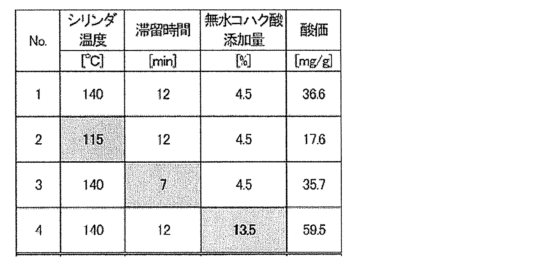
- the chemical modification shown in the first step was carried out with succinic anhydride under the following reaction conditions (Condition 1) to (Condition 4), and the difference in acid values for measuring the degree of chemical modification was determined.
- a separator was produced in which the dry state of cellulose after washing the unreacted hydrophobic chemical shown in the second step was changed to the conditions of 1-5.
- a twin-screw extruder shown in the first step of cellulose fiber raw material (Asahi Kasei Chemicals: Theolas FD101, average particle size 50 ⁇ m) and succinic anhydride (Tokyo Chemical Industry Co., Ltd.) at a ratio of 95.5: 4.5.
- Reaction was carried out in (Nippon Steel Works: TEX30, first extruder (4) in FIG. 1) to obtain chemically modified cellulose.
- the screw in the twin screw extruder at this time is constituted by a flight arrangement, a kneading shape, and a torpedo shape screw arrangement optimized for L / D as shown in FIG.
- the reaction temperature at this time is 100 ° C. to 150 ° C.
- the liquid feed pump is used for the thin film evaporator 30 shown in FIG. 4 (manufactured by Asahi Seisakusho, corresponding to the dryer 12 in FIG. 1) while stirring at a rotational speed of 180 rpm. Injected.
- the temperature of the evaporator was set to 120 ° C. so that the drying time was 2 minutes, and the rotation speed of the thin film forming wiper was adjusted.
- the dried cellulose was collected from the lower part of the apparatus, and the dry state of the cellulose was evaluated.
- acetone generated in the drying process was cooled in a condenser in which a refrigerant at ⁇ 10 ° C. was circulated and recovered in a liquid state.
- the obtained chemically modified cellulose powder was added to liquid paraffin (manufactured by Moresco: P-350P) (cellulose is 1% by mass with respect to liquid paraffin), and the liquid It is injected into a twin-screw extruder (second extruder 19) using an auxiliary pump, and the concentration of the resin with respect to a slurry of ultrahigh molecular weight polyethylene (manufactured by Mitsui Chemicals: Hi-Zex 030S, liquid paraffin and chemically modified cellulose is 30% by mass) and extruded from the T-die 23 to form a sheet.
- liquid paraffin manufactured by Moresco: P-350P
- the concentration of the resin with respect to a slurry of ultrahigh molecular weight polyethylene manufactured by Mitsui Chemicals: Hi-Zex 030S, liquid paraffin and chemically modified cellulose is 30% by mass
- the screw of the twin screw extruder (second extruder 19) has two screws having a combination including at least two of a flight shape, a kneading shape, and a gear shape in which L / D shown in FIG. 3 is optimally adjusted.
- a screw extruder was used. Sheets extruded from a T-die and cast-formed are stretched 6 times in the machine direction (M) and 7 times in the width direction (TD) by a table tenter device 31 (manufactured by Toyo Seiki Co., Ltd.), and have a thickness of 10 ⁇ m. Film was obtained. In order to remove the liquid paraffin in the film, as shown in FIG.
- the acid value which shows the chemical modification degree of the obtained chemically modified cellulose was performed by the acid value measuring method (JIS K2501) generally used.
- the acid value is defined as the number of mg of potassium hydroxide required to neutralize the acidic substance contained in 1 g of sample.
- the acid value indicates the amount of succinic anhydride added to the cellulose surface, and it can be determined that the higher the value, the more hydrophobic.
- 1 g of cellulose for evaluation was first weighed in a 100 ml beaker, 10 ml of distilled water and acetone were added, and the mixture was stirred with a magnetic stirrer at 400 rpm for 10 minutes. Next, the mixed solution was titrated with a 0.1N KOH-ethanol solution while stirring at 200 rpm, and the acid value was measured.
- each characteristic value of the separator was calculated by the following method and verified as a system by comparing with the separator characteristic manufactured by the batch system shown in Comparative Example 1.
- Thermal contraction rate The prepared sheet was cut into a 50 mm ⁇ 50 mm square, and then left in an oven at 100 ° C. and 120 ° C. After 1 hour, the sheet is taken out and the dimensional change before and after standing in the oven is measured.
- Tensile strength After the produced sheet was cut into a dumbbell shape, it was stretched using a tensile tester (manufactured by Shimadzu Corporation: AG100N) at a test speed of 50 mm / min until the sheet broke. The tensile strength was the maximum load until breakage.
- Air permeability After the produced film was cut into a 50 mm ⁇ 50 mm square, the time taken for 100 cc of air to pass was measured using a JISK-compliant air permeability meter (manufactured by TESTIMM MACHINES INC.). .
- Puncture strength The prepared film was cut into a 50 mm ⁇ 50 mm square, and then the strength until the film was broken was measured using a puncture strength meter (KES-G5, manufactured by Kato Tech Co.). The puncture strength was measured at 10 points with each sample, and the average value was obtained.
- Surface observation The produced sheet was subjected to platinum deposition with a thickness of 0.3 nm using a vacuum deposition apparatus (E-1045 manufactured by Hitachi High-Tech). The surface of this sheet was observed using FE-SEM (SUPRA55VP manufactured by Carl Zeiss).
- Dispersion state Since cellulose has oxygen in its molecular structure, the dispersion state of cellulose in the film was evaluated by oxygen mapping using EDX (Aztec Energy Oxford Instruments).
- Example 2 the system of Example 2 is characterized in that a secondary chemical modification / cleaning step 2A is added after the cleaning / drying step 2 of the system of FIG.
- a second dryer 12 ⁇ / b> A is provided between the mixer 13 and the stirrer 14, and a hexane tank 35 and a PO tank 36 are connected to the weighing machine 13 via a liquid feed pump 37.
- the secondary chemical modification / cleaning step 2A shown in FIG. 10 may be performed after the second step of the first embodiment shown in FIG.
- the cellulose raw material chemically treated with succinic anhydride is washed and dried, it is further chemically modified with propylene oxide (PO) to improve the dispersibility and stability of nanocellulose fibers in various resins. It is effective.
- the reaction vessel is equipped with a facility capable of adjusting the temperature and pressure so that the secondary chemical modification can be performed, and has a metering device and a valve capable of supplying a fixed amount of CeNF after the primary modification, and a PO in the reactor.
- FIG. 10 shows an example of a system having a mechanism that can supply the optimum amount of CeNF corresponding to the supply amount of CeNF. Table 1 also shows the physical properties when the separator was manufactured by this system.
- FIG. 11 shows a conventional CeNF composite separator manufacturing system. This system is divided into an upstream process 50 and a downstream process 51.
- the cellulose raw material and succinic anhydride in the state A) are placed in a chemical modification apparatus 52 having a pressure kneader at a weight ratio of 95.5: 45. And kneading at 125 ° C. for 20 minutes to obtain a cellulose raw material in the state of B). Thereafter, unreacted substances were removed with acetone to prepare an aqueous suspension containing 5% by mass of cellulose.
- Results Comparison Table 2 shows the acid values when the chemical modification conditions of Example 1 were changed to 1 to 4.
- the acid value is about 17 mg / g, and the hydrophobicity is low.
- the other conditions were 35 mg / g or more, and the composite state was equal to or higher than condition 1.
- the chemically modified cellulose raw material obtained under condition 3 in Table 2 is washed with acetone and then dried under conditions 1 to 5 in Table 3.
- the cellulose was in a well-dried state.
- Under condition 2 with a drying temperature of 100 ° C. and a drying time of 1 minute, wet cellulose was obtained.
- Under condition 3 with a drying temperature of 80 ° C. and a drying time of 5 minutes, dried cellulose was obtained.
- FIG. 7 and 8 show SEM images of the separator films produced in Condition 1 and Example 2 of Example 1.
- FIG. FIG. 9 shows the result of oxygen mapping of the Condition 1 film of Example 1 by EDX. From the analysis result of FIG. 9, it is inferred that cellulose present in the resin is uniformly dispersed because oxygen that is present in the cellulose molecules indicated by the bright spots and oxygen that is not present in the polyethylene molecules is dispersed without uneven distribution. .
- Table 1 above shows the measurement results of separator characteristics (air permeability, puncture strength, heat shrinkage rate) of Example 1, Example 2, and Comparative Example.
- the conditions of Example 1 are good, the dry state is indicated by a circle in Table 2 above, the separator obtained by combining the chemically modified cellulose and the thermoplastic resin obtained continuously, and the starburst shown in the comparative example It was confirmed that the composite separator of cellulose and resin made into nanofibers by the treatment has almost the same characteristics.
- a defibrating apparatus which has been performed in a conventional batch, a cellulose and a resin are once combined to create a pellet, and a process and apparatus using the pellet as a raw material Was able to be omitted, and the device could be completed by a series of systems for the chemical modification treatment in the extruder and the conversion of cellulose into nanofibers by defibration.
- the present invention continuously provides functions that can dramatically improve the dispersibility and stability of cellulose fiber raw materials in resins, which are required when mixing composites of cellulose and resins that are abundant in nature. It can be added, and cellulose defibration in the reactor can be combined with a thermoplastic resin.
Abstract
Description
このような背景もあり、プラスチック複合材は、軽量かつ強度特性に優れ、低コストで廃棄する際の環境負荷が小さいことが望まれている。これらの特徴を持ち合わせた強化繊維として、天然資源として豊富に存在し、強度特性に優れるセルロース繊維が注目されており、研究が盛んに行われている。 In recent years, fiber reinforced plastics in which fiber materials and thermoplastic resins are combined are used in various products. As an example, GFRP, CFRP, etc., in which glass fiber, carbon fiber, and the like are combined with a resin are widely used in fields such as automobile parts, sports goods, housing materials, and home appliances. A product in which these fibers are combined exhibits excellent strength characteristics. On the other hand, there is a difficulty in the disposal method when disposing of the product, and it is often difficult to recycle, and there is a problem that the environmental load is large.
Against such a background, it is desired that the plastic composite material is light in weight, excellent in strength properties, and low in environmental burden when discarded at low cost. Cellulosic fibers that are abundant as natural resources and have excellent strength properties are attracting attention as reinforcing fibers having these characteristics, and research is actively conducted.
このように、セルロースを複合材料として利用するために以下の例で示される特許文献1~3が公開されている。 In addition, many studies have been conducted on the composite of cellulose nanofibers and resins having a cellulose diameter of nano-order. Usually, the fiber diameter used for papermaking, filter membranes, etc. is about 10 μm to 50 μm. Cellulose nanofibers, on the other hand, have functions that reinforce between resin crystals different from the case of using normal fibers by reducing the fiber diameter to 1/100 to 1/10000, which is nano-order. Be expected. In this way, fiber reinforced plastics made by combining cellulose nanofibers and resin have a lower environmental impact than conventional fiber reinforced plastics, and have developed a function that has not been known so far. Expansion is expected.
Thus, in order to use cellulose as a composite material,
つまり、本発明は、微粉状セルロース繊維材料と疎水性化学物質とを反応させて得られる化学修飾セルロースを連続的に製造するための装置、及びその装置で用いられる方法を提供する。
また、本発明は、微粉状セルロース繊維原料からセルロース複合樹脂を連続的に製造するため装置、及びその装置で用いられる方法を提供する。
また、本発明は、微粉状セルロース繊維原料から連続的にリチウムイオン電池用セルロースナノファイバー複合セパレータ連続的に製造するための装置、及びその装置より製造されたリチウムイオン電池用セルロースナノファイバー複合セパレータを提供する。 The present invention has been made to solve the conventional problems as described above.
That is, the present invention provides an apparatus for continuously producing chemically modified cellulose obtained by reacting a finely divided cellulose fiber material with a hydrophobic chemical substance, and a method used in the apparatus.
Moreover, this invention provides the apparatus used in order to manufacture a cellulose composite resin continuously from a fine powdery cellulose fiber raw material, and the method used with the apparatus.
The present invention also provides a device for continuously producing a cellulose nanofiber composite separator for lithium ion batteries from a finely divided cellulose fiber raw material, and a cellulose nanofiber composite separator for lithium ion batteries produced from the device. provide.
微粉状セルロース繊維原料(6)と疎水性化学物質を搬送するための第1機構(6a)と、
前記セルロース繊維原料(6)と前記疎水性化学物質を導入するためのホッパー(5)及び昇温機構・昇圧機構・脱気機構を有し、かつ混練のためのスクリュピースを有する押出機(4)と、
前記押出機に接続された溶剤槽(25)、並びに
前記溶剤槽に接続された乾燥装置(12)を有する化学修飾セルロース連続製造装置を提供する。 Specifically, the present invention provides:
A first mechanism (6a) for conveying the finely divided cellulose fiber raw material (6) and the hydrophobic chemical substance;
Extruder (4) having a hopper (5) for introducing the cellulose fiber raw material (6) and the hydrophobic chemical substance, a temperature raising mechanism, a pressure raising mechanism, a deaeration mechanism, and a screw piece for kneading )When,
There is provided a chemically modified cellulose continuous production apparatus having a solvent tank (25) connected to the extruder and a drying apparatus (12) connected to the solvent tank.
微粉状セルロース繊維原料(6)及び疎水性化学物質を、昇温機構・昇圧機構・脱気機構を有し、かつ混練のためのスクリュピースを有する押出機に導入し、前記疎水性化学物質を溶融させ、前記疎水性化学物質と前記セルロースと混練し、さらにこれらを反応させて化学修飾セルロースを得る、第1工程、及び
前記押出機から化学修飾セルロースを吐出させて溶剤槽(25)に導入し、前記化学修飾セルロースを有機溶剤に分散させて分散液を得た後、前記溶剤槽に接続する乾燥装置(12)へ該分散液を注入して、分散液を乾燥させ有機溶剤と分離する、第2工程を含む、
化学修飾セルロース連続製造方法を提供する。 The present invention also provides:
The finely divided cellulose fiber raw material (6) and the hydrophobic chemical substance are introduced into an extruder having a temperature raising mechanism, a pressure raising mechanism, a degassing mechanism, and a screw piece for kneading, and the hydrophobic chemical substance is introduced into the extruder. Melting, kneading the hydrophobic chemical and the cellulose, and further reacting them to obtain chemically modified cellulose, the first step, and discharging the chemically modified cellulose from the extruder and introducing it into the solvent tank (25) Then, after dispersing the chemically modified cellulose in an organic solvent to obtain a dispersion, the dispersion is poured into a drying device (12) connected to the solvent tank, and the dispersion is dried and separated from the organic solvent. Including the second step,
A method for continuously producing chemically modified cellulose is provided.
微粉状セルロース繊維原料(6)と疎水性化学物質を搬送するための第1機構(6a)と、
前記セルロース繊維原料(6)と前記疎水性化学物質を導入するためのホッパー(5)及び昇温機構・昇圧機構・脱気機構を有し、かつ混練のためのスクリュピースを有する第1押出機と、
前記第1押出機に接続された溶剤槽(25)と、
前記溶剤槽に接続された乾燥装置(12)と、
パラフィンタンク(26)と
該パラフィンタンク(26)に接続され、かつ計量機(13)を介して乾燥機に接続された攪拌機(14)と、
該攪拌機(14)に接続され、かつ、熱可塑性樹脂を導入するためのホッパー(28)、及び昇温機構、昇圧機構、脱気機構を備え、混練のためのスクリュピースを有する第2押出機(19)と、
熱可塑性樹脂を前記第2押出機に導入する機構(20)と
を有するセルロース複合樹脂連続製造装置を提供する。 The present invention also provides:
A first mechanism (6a) for conveying the finely divided cellulose fiber raw material (6) and the hydrophobic chemical substance;
A first extruder having a hopper (5) for introducing the cellulose fiber raw material (6) and the hydrophobic chemical substance, a temperature raising mechanism, a pressure raising mechanism, a deaeration mechanism, and a screw piece for kneading. When,
A solvent tank (25) connected to the first extruder;
A drying device (12) connected to the solvent tank;
A paraffin tank (26) and a stirrer (14) connected to the paraffin tank (26) and connected to the dryer via a weighing machine (13);
A second extruder connected to the agitator (14) and provided with a hopper (28) for introducing a thermoplastic resin, a temperature raising mechanism, a pressure raising mechanism, and a deaeration mechanism, and having a screw piece for kneading (19)
There is provided a cellulose composite resin continuous production apparatus having a mechanism (20) for introducing a thermoplastic resin into the second extruder.
微粉状セルロース繊維原料(6)及び疎水性化学物質を、昇温機構・昇圧機構・脱気機構を有し、かつ混練のためのスクリュピースを有する第1押出機(4)に導入し、前記疎水性化学物質を溶融させ、前記疎水性化学物質と前記セルロースと混練し、さらにこれらを反応させて化学修飾セルロースを得る、第1工程、
前記第1押出機(4)から化学修飾セルロースを吐出させて溶剤槽(25)に導入し、前記化学修飾セルロースを有機溶剤に分散させて分散液を得た後、前記溶剤槽(25)に接続する乾燥装置(12)へ該分散液を注入して、分散液を乾燥させ有機溶剤と分離する、第2工程、及び
前記乾燥された化学修飾セルロースをパラフィンと混合し、その後、この混合物と熱可塑性樹脂を昇温機構、昇圧機構、脱気機構を備え、かつ混練のためのスクリュピースを持つ第2押出機に導入して、これらを混練する、第3工程を含む、
セルロース複合樹脂連続製造方法を提供する。 The present invention also provides:
The finely divided cellulose fiber raw material (6) and the hydrophobic chemical substance are introduced into a first extruder (4) having a temperature raising mechanism, a pressure raising mechanism, a deaeration mechanism, and a screw piece for kneading, and A first step of melting a hydrophobic chemical substance, kneading the hydrophobic chemical substance and the cellulose, and further reacting them to obtain a chemically modified cellulose;
After the chemically modified cellulose is discharged from the first extruder (4) and introduced into the solvent tank (25), the chemically modified cellulose is dispersed in an organic solvent to obtain a dispersion, and then into the solvent tank (25). Injecting the dispersion into a drying apparatus (12) to be connected, drying the dispersion and separating it from the organic solvent, and the second step, and mixing the dried chemically modified cellulose with paraffin; Introducing a thermoplastic resin into a second extruder having a temperature raising mechanism, a pressure raising mechanism, a deaeration mechanism, and having a screw piece for kneading, and kneading these, including a third step,
A method for continuously producing a cellulose composite resin is provided.
上記セルロース複合樹脂連続製造装置に接続されたTダイ又はストランドダイを有する、リチウムイオン電池用セルロースナノファイバー複合セパレータ連続製造装置、及び、該リチウムイオン電池用セルロースナノファイバー複合セパレータ連続製造装置を用いて製造されたリチウムイオン電池用セルロースナノファイバー複合セパレータを提供する。 Furthermore, the present invention provides
Using the cellulose nanofiber composite separator continuous production apparatus for lithium ion batteries, and the cellulose nanofiber composite separator continuous production apparatus for lithium ion batteries, having a T die or a strand die connected to the cellulose composite resin continuous production apparatus A produced cellulose nanofiber composite separator for a lithium ion battery is provided.
また、本発明では、自然界に豊富に存在するセルロース繊維原料中のセルロースと樹脂を混合してリチウムイオン電池用セルロースナノファイバー複合化セパレータを製造する時に必要な、セルロース繊維原料の樹脂中におけるミクロフィブリル化と分散性および安定性を飛躍的に向上できる機能を連続的に追加することができる。 As described above, according to the present invention, it is possible to continuously produce cellulose that has been chemically modified to improve the dispersion state in the thermoplastic resin, and further to remove and dry the unreacted hydrophobic compound. It is possible to carry out the process continuously and to achieve a combination of cellulose defibration and thermoplastic resin in the reactor.
Further, in the present invention, the microfibril in the cellulose fiber raw material resin, which is necessary when the cellulose nanofiber composite separator for a lithium ion battery is manufactured by mixing cellulose and the resin in the cellulose fiber raw material abundant in nature. Functions that can dramatically improve the efficiency and dispersibility and stability can be added continuously.
まず、本発明は、上記目的を達成するために、以下の3つの工程を実施できるシステム(装置:図1)でセルロースを化学修飾し、洗浄・乾燥し、解繊し樹脂と複合化する。
前述の第1工程~第3工程を説明する前に図1のセルロース化学修飾・洗浄・乾燥・セルロースナノファイバー複合セパレータ製造システムの概要について説明する。
図1は本発明におけるセルロース化学修飾・洗浄・乾燥・セルロースナノファイバー複合セパレータ製造システムの概要を示している。
図1において、符号1で示されるものは、化学修飾工程であり、スクリュ式押出機4のホッパー5には、第1機構6aとしてのフィーダ6を介してセルロース原料6bとセルロースを疎水化する疎水性化学物質が供給され、真空ポンプ7を用いて真空ベント8から真空引きが行われつつ化学修飾物質が溶融混練されながらセルロースナノファイバー(CeNF)と混練されることでセルロース分子表面が化学修飾される。その後、溶剤(例えばアセトン)を含む溶剤槽25で未反応疎水性化学物質が洗浄された後、微粉状セルロースが分散液に対して1~60質量%の濃度で含まれるスラリー(分散液)10がスラリー輸送ポンプ9に送られる。 Hereinafter, preferred embodiments of a method for continuously producing chemically modified cellulose and a continuous production system for cellulose nanofiber composite separators according to the present invention will be described with reference to the drawings.
First, in order to achieve the above object, in the present invention, cellulose is chemically modified by a system (apparatus: FIG. 1) capable of performing the following three steps, washed and dried, defibrated, and combined with a resin.
Before describing the first to third steps, the outline of the cellulose chemical modification / cleaning / drying / cellulose nanofiber composite separator manufacturing system of FIG. 1 will be described.
FIG. 1 shows an outline of a system for producing cellulose chemical modification / cleaning / drying / cellulose nanofiber composite separator in the present invention.
In FIG. 1, what is shown by the code |
前記第2スクリュ式押出機19には、熱可塑性樹脂原料を導入する機構20(例えばフィーダ)からの熱可塑性樹脂原料21が同時に送られて、前記液添ポンプ18からのパラフィンと化学修飾セルロースを含む液状原料22と共に前記第2スクリュ式押出機19にて混練されて、図示しないTダイ23又はストランドダイ24に送られるように構成されている。 The
A thermoplastic resin
化学修飾セルロースを得る工程とこの工程で使用する装置
第1工程では微粉状のセルロース繊維原料及び疎水性化学物質を混合し、反応させる。
最初に、一定量のセルロース繊維原料と疎水性化学物質をフィーダ(6)に導入し、セルロース繊維原料と疎水性化学物質の混合物を得る。
次に、セルロース繊維原料と疎水性化学物質の混合物をフィーダ(6)からホッパー(5)へ供給する。この混合物は溶融混練が可能な機能を有する装置(例えば、二軸押出機、単軸押出機、ニーダーなど)に導入される。この装置で混合物は混練されて、化学修飾されたセルロース原料が装置前方に搬送される。この工程で使用する押出機は昇温機構、昇圧機構及び脱気機構を有する。このとき押出機はフライト形状、ニーディング形状、トーピード形状のうち、少なくとも2つ以上の組み合わせからなり、そのL/D(押出機シリンダ内径:D,スクリュピース長:L)を調整したスクリュピースを持ち、押出機内の混練強度と滞留時間を調整できる二軸押出機が望ましい。搬送能力を有する装置を用いて反応処理を行う場合、反応時間は滞留時間と等しい。そのため、装置内におけるセルロースの滞留時間の目標に応じて各種スクリュ形状のピースを組み替えて、反応時間と混練強度を調節する。特にトーピードは、円筒内壁で弱いせん断応力を生じさせることから、混練し過ぎず、滞留時間を長くする上で、有効となる。また、セルロースの化学修飾状態により、反応温度・圧力を調整する。 (First step)
The step of obtaining chemically modified cellulose and the apparatus used in this step In the first step, a finely divided cellulose fiber raw material and a hydrophobic chemical substance are mixed and reacted.
First, a certain amount of the cellulose fiber raw material and the hydrophobic chemical substance are introduced into the feeder (6) to obtain a mixture of the cellulose fiber raw material and the hydrophobic chemical substance.
Next, a mixture of the cellulose fiber raw material and the hydrophobic chemical substance is supplied from the feeder (6) to the hopper (5). This mixture is introduced into an apparatus (for example, a twin screw extruder, a single screw extruder, a kneader, etc.) having a function capable of melt kneading. In this apparatus, the mixture is kneaded and the chemically modified cellulose raw material is conveyed to the front of the apparatus. The extruder used in this step has a temperature raising mechanism, a pressure raising mechanism, and a deaeration mechanism. At this time, the extruder is composed of a combination of at least two of a flight shape, a kneading shape, and a torpedo shape, and a screw piece whose L / D (extruder cylinder inner diameter: D, screw piece length: L) is adjusted. It is desirable to use a twin screw extruder that can adjust the kneading strength and residence time in the extruder. When the reaction process is performed using an apparatus having a conveyance capability, the reaction time is equal to the residence time. Therefore, according to the target of the residence time of the cellulose in an apparatus, various screw-shaped pieces are rearranged and reaction time and kneading | mixing intensity | strength are adjusted. In particular, the torpedo generates a weak shear stress on the inner wall of the cylinder, so that it is not excessively kneaded and is effective in extending the residence time. The reaction temperature and pressure are adjusted according to the chemical modification state of cellulose.
本発明では、上記の疎水性化学物質を組み合わせて用いてもよく、また必要に応じて、顔料などを用いてもよい。 Of these, maleic anhydride, succinic anhydride, and phthalic anhydride are preferred because they are industrially applicable and easily gasified.
In the present invention, the above hydrophobic chemical substances may be used in combination, and a pigment or the like may be used as necessary.
未反応疎水性化学物質の洗浄・乾燥する工程とこの工程で使用する装置
第1工程で化学修飾したセルロースを反応装置(図1では第1押出機4)の先端より吐出させて有機溶剤中に投入し、化学修飾セルロースの分散液を得る。このときの分散液におけるセルロースの濃度は1質量%~60質量%が好ましく、2質量%~40質量%が更に好ましい。
有機溶剤としては、アセトン、エチルメチルケトン、ペンタン、ヘキサン、ヘプタン、シクロヘキサン、ベンゼン、ジエチルエーテル等の公知の溶剤が使用でき、アセトンが好ましい。
未反応の疎水性物質は有機溶剤へ移行し、化学修飾セルロースが洗浄される。 (Second step)
Steps for washing and drying unreacted hydrophobic chemicals and equipment used in this step Cellulose chemically modified in the first step is discharged from the tip of the reaction device (
As the organic solvent, known solvents such as acetone, ethyl methyl ketone, pentane, hexane, heptane, cyclohexane, benzene and diethyl ether can be used, and acetone is preferred.
Unreacted hydrophobic material moves to the organic solvent, and the chemically modified cellulose is washed.
なお、乾燥時間は、乾燥温度、分散液におけるセルロースの濃度や分散液の量などで調製されるが、通常1~30分、好ましくは1~15分、より好ましくは1~10分、更に好ましくは1~5分、なお更に好ましくは1~2分である。 Next, the dispersion liquid of cellulose after chemical modification is poured into a drying apparatus using a liquid feed pump or the like. As the drying apparatus, a medium fluidized dryer, a drum dryer, a thin film evaporator, a spray dryer, a single screw extruder, a twin screw extruder, or the like is preferable. Two or more of these may be used. As the apparatus, an apparatus having a temperature raising mechanism for efficiently drying an organic solvent is preferable, and an apparatus having a vacuum mechanism is more preferable. Moreover, you may attach the distillation apparatus, the condensing apparatus, etc. which collect | recover the organic solvent which volatilized using these drying apparatuses. Furthermore, it is preferable that various parts used in the drying section of the apparatus have explosion-proof specifications. Further, when the organic solvent is volatilized, the unreacted hydrophobic chemical substance is also volatilized.
The drying time is adjusted depending on the drying temperature, the concentration of cellulose in the dispersion, the amount of the dispersion, and the like, but is usually 1 to 30 minutes, preferably 1 to 15 minutes, more preferably 1 to 10 minutes, and still more preferably. Is 1 to 5 minutes, still more preferably 1 to 2 minutes.
また、製造初期段階で乾燥機(12)に注入する量を調整する必要がある。そのため、溶剤槽(25)から送り出された分散液(スラリー)の一部を乾燥機(12)に到達する前に溶剤槽(25)に戻す。しかしながら、分散液は化学修飾セルロースを含んでいることからCeNFろ過フィルター(27)でろ過されて溶剤のみ溶剤槽(25)に戻る。このようにして、溶剤槽(25)の中の溶剤が空になることを防ぐ。 When secondary chemical modification is performed on cellulose, a plurality of reaction apparatuses and washing / drying apparatuses may be combined.
In addition, it is necessary to adjust the amount injected into the dryer (12) in the initial stage of production. Therefore, a part of the dispersion liquid (slurry) sent out from the solvent tank (25) is returned to the solvent tank (25) before reaching the dryer (12). However, since the dispersion contains chemically modified cellulose, it is filtered through a CeNF filter (27) and only the solvent returns to the solvent tank (25). In this way, the solvent in the solvent tank (25) is prevented from being emptied.
セルロースナノファイバー複合化セパレータ製造工程及びこの工程で使用する装置
次いで、上記の方法により得られた化学修飾セルロースは計量機(13)を介して撹拌機(12)に移動する。撹拌機(14)でパラフィンタンク(26)から送られる流動パラフィン(17)に分散させて、スラリー(分散液)を得る。このとき、セルロースの濃度は流動パラフィンに対して0.1質量%~40質量%が好ましく、0.1質量%~30質量%が更に好ましい。 (Third step)
Cellulose nanofiber composite separator manufacturing process and apparatus used in this process Next, the chemically modified cellulose obtained by the above method moves to the stirrer (12) via the meter (13). Disperse in the liquid paraffin (17) sent from the paraffin tank (26) by the stirrer (14) to obtain a slurry (dispersion). At this time, the concentration of cellulose is preferably 0.1% by mass to 40% by mass, and more preferably 0.1% by mass to 30% by mass with respect to the liquid paraffin.
このとき、熱可塑性樹脂の濃度はスラリーに対して、好ましくは10質量%~50質量%、より好ましくは20質量%~40質量%である。 The slurry is mixed with a thermoplastic resin to obtain a cellulose composite resin. Specifically, it has a hopper (28) that can be introduced into a reactor for mixing slurry and thermoplastic resin, and a liquid addition pump, and is kneaded with powdered or microfibrillated cellulose that has been chemically modified by melting the thermoplastic resin. Kneaded using a device (second extruder (19)) (for example, twin screw extruder, single screw extruder, kneader) that has the function of raising the temperature, raising the pressure, and degassing to a possible condition. And a composite of thermoplastic resin and paraffin. At this time, as the screw, at least one of a flight shape, a kneading shape, and a gear shape is combined, and L / D is optimized. In particular, the gear shape is important for enhancing the effect of dispersing the cellulose raw material in the thermoplastic resin.
At this time, the concentration of the thermoplastic resin is preferably 10% by mass to 50% by mass and more preferably 20% by mass to 40% by mass with respect to the slurry.
(実施例1)
前述の第1~第3工程からなるシステムの1実施例を図1に示している。図1のセルロースの化学修飾・洗浄乾燥・複合樹脂製造システムを用いて、リチウムイオン電池(LIB)用セパレータを製作した。なお、製作条件として、前記第1工程で示される化学修飾は無水コハク酸を以下の(条件1)~(条件4)の反応条件で行い、化学修飾度合いを測る酸価の違いを求めた。また、前記第2工程で示される未反応疎水性化学物質を洗浄した後のセルロースの乾燥状態を1~5の条件に変えたセパレータを製作した。 Hereinafter, embodiments of the present invention will be described with reference to the drawings.
Example 1
FIG. 1 shows an embodiment of a system composed of the aforementioned first to third steps. A separator for a lithium ion battery (LIB) was manufactured using the chemical modification / cleaning / drying / composite resin production system of cellulose in FIG. As production conditions, the chemical modification shown in the first step was carried out with succinic anhydride under the following reaction conditions (Condition 1) to (Condition 4), and the difference in acid values for measuring the degree of chemical modification was determined. In addition, a separator was produced in which the dry state of cellulose after washing the unreacted hydrophobic chemical shown in the second step was changed to the conditions of 1-5.
熱収縮率:作製したシートを50mm×50mm角に切出した後、100℃及び120℃のオーブン内に静置した。1時間後、シートを取り出し、オーブン内の静置前後での寸法変化を計測する。 Further, each characteristic value of the separator was calculated by the following method and verified as a system by comparing with the separator characteristic manufactured by the batch system shown in Comparative Example 1.
Thermal contraction rate: The prepared sheet was cut into a 50 mm × 50 mm square, and then left in an oven at 100 ° C. and 120 ° C. After 1 hour, the sheet is taken out and the dimensional change before and after standing in the oven is measured.
透気度 :作製したフィルムを50mm×50mm角に切出した後、JISKに準拠した透気度計を(TESTIMG MACHINES INC.社製)を用いて、100ccの空気が通過するまでの時間を測定した。
突刺強度:作製したフィルムを50mm×50mm角に切出した後、JISKに準拠した突刺強度計(カトーテック社製:KES-G5)を用いて、フィルムが破損するまでの強度を測定した。突刺強度は、各サンプル付き10箇所測定し、平均値を求めた。
表面観察:作製したシートを真空蒸着装置(日立ハイテク社製E-1045)で0.3nmの厚みの白金蒸着を施した。このシートをFE-SEM(カールツァイス社製SUPRA55VP)を使用して表面観察を行った。
分散状態:セルロースは酸素を分子構造中に持つため、EDX(Aztec Energy Oxford Instruments)を用いた酸素マッピングにより、フィルム中におけるセルロースの分散状態を評価した。 Tensile strength: After the produced sheet was cut into a dumbbell shape, it was stretched using a tensile tester (manufactured by Shimadzu Corporation: AG100N) at a test speed of 50 mm / min until the sheet broke. The tensile strength was the maximum load until breakage.
Air permeability: After the produced film was cut into a 50 mm × 50 mm square, the time taken for 100 cc of air to pass was measured using a JISK-compliant air permeability meter (manufactured by TESTIMM MACHINES INC.). .
Puncture strength: The prepared film was cut into a 50 mm × 50 mm square, and then the strength until the film was broken was measured using a puncture strength meter (KES-G5, manufactured by Kato Tech Co.). The puncture strength was measured at 10 points with each sample, and the average value was obtained.
Surface observation: The produced sheet was subjected to platinum deposition with a thickness of 0.3 nm using a vacuum deposition apparatus (E-1045 manufactured by Hitachi High-Tech). The surface of this sheet was observed using FE-SEM (SUPRA55VP manufactured by Carl Zeiss).
Dispersion state: Since cellulose has oxygen in its molecular structure, the dispersion state of cellulose in the film was evaluated by oxygen mapping using EDX (Aztec Energy Oxford Instruments).
実施例1の乾燥工程において、薄膜蒸発機内の温度を120℃として、乾燥を行った。その他の条件は、実施例1と同じである。
(条件2)
実施例1の乾燥工程において、薄膜蒸発機内の温度を100℃として、乾燥を行った。その他の条件は、実施例1と同じである。
(条件3)
実施例1の乾燥工程において、薄膜蒸発機内の温度を80℃として、乾燥時間を5分となるように乾燥を行った。その他の条件は、実施例1とおなじである。
(条件4)
実施例1の乾燥工程において、薄膜蒸発機内の温度を120℃として、乾燥時間を1分となるように乾燥を行った。その他の条件は、実施例1と同じである。
(条件5)
実施例1の乾燥工程において、薄膜蒸発機内の温度を130℃として、乾燥時間を1分となるように乾燥を行った。その他の条件は、実施例1と同じである。 (Condition 1)
In the drying process of Example 1, drying was performed at a temperature in the thin film evaporator of 120 ° C. Other conditions are the same as those in the first embodiment.
(Condition 2)
In the drying process of Example 1, drying was performed at a temperature in the thin film evaporator of 100 ° C. Other conditions are the same as those in the first embodiment.
(Condition 3)
In the drying process of Example 1, the temperature in the thin film evaporator was set to 80 ° C., and drying was performed so that the drying time was 5 minutes. Other conditions are the same as those in Example 1.
(Condition 4)
In the drying process of Example 1, the temperature in the thin film evaporator was 120 ° C., and drying was performed so that the drying time was 1 minute. Other conditions are the same as those in the first embodiment.
(Condition 5)
In the drying process of Example 1, the temperature in the thin film evaporator was 130 ° C., and drying was performed so that the drying time was 1 minute. Other conditions are the same as those in the first embodiment.
システムとしては、図1の実施例1の第2工程後に図10における2次的な化学修飾・洗浄工程2Aを行なってもよい。ここでは、無水コハク酸で化学修飾処理したセルロース原料を洗浄・乾燥した後に、さらに多様な樹脂中でのナノセルロース繊維の分散性と安定性を向上させるために、プロピレンオキシド(PO)で化学修飾すると効果的である。この2次化学修飾が行えるように温度・圧力が調節可能な設備を備えた反応容器とされに1次修飾後のCeNFを一定量供給できる計量機とバルブを有し、かつ反応器中にPOをCeNFの供給量に最適に対応して供給できる機構を有するシステム例を図10に示した。このシステムにてセパレータを製作したときの物性値を表1に併記した。 (Example 2)
As a system, the secondary chemical modification /

図11に従来のCeNF複合セパレータ製造システムを示した。このシステムは上流工程50と下流工程51に分けられ、上流工程50では加圧ニーダを有する化学修飾装置52内でA)の状態のセルロース原料と無水コハク酸を、95.5:45の重量比で混合し、125℃、20分間混練した後、B)の状態のセルロース原料を得る。その後、アセトンで未反応物を除去してセルロースを5質量%含む水懸濁液を調製した。次に、これを解繊装置53であるスターバースト(スギノマシン製:HJP25080)で超高圧対向衝突処理し、C)の状態のナノファイバー化した。その後、CeNF水懸濁液を超高分子量ポリエチレン(三井化学社製:ハイゼックスミリオン030S)とCeNF複合原料製造装置54である混練機(二軸押出機)55(TEX30)内で混練して、D)のセルロースナノファイバー複合化ペレットを作製した。これを実施例1のセパレータ製造工程3で示した下流工程でフィルム化した。このシステムにてセパレータを製作したときの物性値を前述の表1に併記した。 (Comparative example)
FIG. 11 shows a conventional CeNF composite separator manufacturing system. This system is divided into an
実施例1の化学修飾条件を1~4に変更した場合の酸価を表2に示す。シリンダ温度条件を変えた場合に酸価は約17mg/gとなり、疎水化が低い状態である。その他の条件は35mg/g以上であり、複合化状態は条件1と同等かそれ以上となった。次に、表2の条件3で得られた化学修飾セルロース原料をアセトンで洗浄後、条件1~5の条件で乾燥した状態を表3に示す。条件1ではセルロースが良好に乾燥した状態となった。乾燥温度100℃、乾燥時間1分の条件2では、湿った状態のセルロースが得られた。乾燥温度80℃、乾燥時間5分とした条件3では、乾燥したセルロースが得られた。乾燥温度120℃、乾燥時間1分とした条件4では、セルロースの乾燥状態が不十分であった。乾燥温度を130℃、乾燥時間1分とした条件5では、乾燥したセルロースが得られた。なお、乾燥温度60℃は、セルロースが乾燥しない温度であり、180℃はセルロースが黄色味を帯びると共に、無水コハク酸分解の可能性があるため、60℃~180℃を乾燥温度最適温度とした。 Results Comparison Table 2 shows the acid values when the chemical modification conditions of Example 1 were changed to 1 to 4. When the cylinder temperature condition is changed, the acid value is about 17 mg / g, and the hydrophobicity is low. The other conditions were 35 mg / g or more, and the composite state was equal to or higher than

実施例1の条件が良好で、前述の表2中に乾燥状態が○で示され、連続的に得られた化学修飾セルロースと熱可塑性樹脂を複合化したセパレータと、比較例で示したスターバースト処理により、ナノファイバー化したセルロースと樹脂の複合セパレータを比較すると、ほぼ同等の特性を有することが確認された。このことから、本発明における化学修飾セルロース連続製造システムを用いることにより、従来のバッチで行なっていた解繊装置とセルロースと樹脂を一旦複合化してペレットを作成し、それを原料とするプロセスと装置が省略でき、押出機内での化学修飾処理と解繊によるセルロースのナノファイバー化を、一連のシステムで完結することが可能である装置とすることができた。 Table 1 above shows the measurement results of separator characteristics (air permeability, puncture strength, heat shrinkage rate) of Example 1, Example 2, and Comparative Example.
The conditions of Example 1 are good, the dry state is indicated by a circle in Table 2 above, the separator obtained by combining the chemically modified cellulose and the thermoplastic resin obtained continuously, and the starburst shown in the comparative example It was confirmed that the composite separator of cellulose and resin made into nanofibers by the treatment has almost the same characteristics. From this, by using the chemically modified cellulose continuous production system in the present invention, a defibrating apparatus, which has been performed in a conventional batch, a cellulose and a resin are once combined to create a pellet, and a process and apparatus using the pellet as a raw material Was able to be omitted, and the device could be completed by a series of systems for the chemical modification treatment in the extruder and the conversion of cellulose into nanofibers by defibration.
2 洗浄・乾燥工程
2A 2次化学修飾・洗浄工程
3 セパレータ製造工程
4 第1押出機
4a 第1機構
5 ホッパー
6 セルロース
7 真空ポンプ
8 真空ベント
9 スラリー輸送ポンプ
10 スラリー
11 ヒータ
12 乾燥機(乾燥工程)
12A 第1装置
13 計量機
14 撹拌機
15 液送ポンプ
17 パラフィン
18 液添ポンプ
19 第2押出機
20 熱可塑性樹脂原料を導入する機構20(フィーダ)
21 熱可塑性樹脂原料
22 液状原料
23 Tダイ
24 ストランドダイ
25 溶剤槽
26 パラフィンタンク
27 CeNFろ過フィルター
28 ホッパー
30 薄膜蒸発機
31 テーブルテンター装置
35 ヘキサンタンク
36 POタンク
50 上流工程
51 下流工程
52 化学修飾装置
53 解繊装置
54 CeNF複合原料製造装置
55 混練機 DESCRIPTION OF
DESCRIPTION OF
Claims (22)
- 微粉状セルロース繊維原料(6)と疎水性化学物質を搬送するための第1機構(6a)と、
前記セルロース繊維原料(6)と前記疎水性化学物質を導入するためのホッパー(5)及び昇温機構・昇圧機構・脱気機構を有し、かつ混練のためのスクリュピースを有する押出機(4)と、
前記押出機に接続された溶剤槽(25)、並びに
前記溶剤槽に接続された乾燥装置(12)を有する化学修飾セルロース連続製造装置。 A first mechanism (6a) for conveying the finely divided cellulose fiber raw material (6) and the hydrophobic chemical substance;
Extruder (4) having a hopper (5) for introducing the cellulose fiber raw material (6) and the hydrophobic chemical substance, a temperature raising mechanism, a pressure raising mechanism, a deaeration mechanism, and a screw piece for kneading )When,
A chemically modified cellulose continuous production apparatus comprising a solvent tank (25) connected to the extruder and a drying apparatus (12) connected to the solvent tank. - 前記微粒状セルロース繊維原料(6)の平均粒子径dが1nm≦d≦150μmである、請求項1に記載の装置。 The apparatus according to claim 1, wherein an average particle diameter d of the finely divided cellulose fiber raw material (6) is 1 nm ≤ d ≤ 150 µm.
- 前記押出機がフライト形状、ニーディング形状、トーピード形状から選択される2種類以上を組み合わせたスクリュピースを有する、請求項1又は2に記載の化学修飾セルロース連続製造装置。 The chemical modified cellulose continuous production apparatus according to claim 1 or 2, wherein the extruder has a screw piece in which two or more types selected from a flight shape, a kneading shape, and a torpedo shape are combined.
- 前記乾燥装置(12)が、媒体流動乾燥機、ドラムドライヤ、薄膜蒸発機、スプレードライヤー、単軸押出機、又は二軸押出機から選択される1種又は2種以上である、請求項1~3のいずれかに記載の化学修飾セルロース連続製造装置。 The drying apparatus (12) is one or more selected from a medium fluidized dryer, a drum dryer, a thin film evaporator, a spray dryer, a single screw extruder, or a twin screw extruder. 4. The chemically modified cellulose continuous production apparatus according to any one of 3 above.
- 微粉状セルロース繊維原料(6)及び疎水性化学物質を、昇温機構・昇圧機構・脱気機構を有し、かつ混練のためのスクリュピースを有する押出機に導入し、前記疎水性化学物質を溶融させ、前記疎水性化学物質と前記セルロースと混練し、さらにこれらを反応させて化学修飾セルロースを得る、第1工程、及び
前記押出機から化学修飾セルロースを吐出させて溶剤槽(25)に導入し、前記化学修飾セルロースを有機溶剤に分散させて分散液を得た後、前記溶剤槽に接続する乾燥装置(12)へ該分散液を注入して、分散液を乾燥させ有機溶剤と分離する、第2工程を含む、
化学修飾セルロース連続製造方法。 The finely divided cellulose fiber raw material (6) and the hydrophobic chemical substance are introduced into an extruder having a temperature raising mechanism, a pressure raising mechanism, a degassing mechanism, and a screw piece for kneading, and the hydrophobic chemical substance is introduced into the extruder. Melting, kneading the hydrophobic chemical and the cellulose, and further reacting them to obtain chemically modified cellulose, the first step, and discharging the chemically modified cellulose from the extruder and introducing it into the solvent tank (25) Then, after dispersing the chemically modified cellulose in an organic solvent to obtain a dispersion, the dispersion is poured into a drying device (12) connected to the solvent tank, and the dispersion is dried and separated from the organic solvent. Including the second step,
Chemically modified cellulose continuous production method. - 前記微粒状セルロース繊維原料(6)の平均粒子径dが1nm≦d≦150μmである、請求項5に記載の化学修飾セルロース連続製造方法。 The method for continuously producing chemically modified cellulose according to claim 5, wherein an average particle diameter d of the finely divided cellulose fiber raw material (6) is 1 nm ≦ d ≦ 150 μm.
- 前記第1工程で、前記疎水性化学物質を前記セルロース繊維原料(6)100質量部に対して0.5質量部以上30質量部以下で含む混合物を混練する、請求項5又は6に記載の化学修飾セルロース連続製造方法。 The said 1st process knead | mixes the mixture which contains the said hydrophobic chemical substance in 0.5 mass part or more and 30 mass parts or less with respect to 100 mass parts of said cellulose fiber raw materials (6). Chemically modified cellulose continuous production method.
- 前記第1工程で、前記セルロース繊維原料(6)及び疎水性化学物質を100℃以上250℃以下で反応させる、請求項5~7のいずれかに記載の化学修飾セルロース連続製造方法。 The chemically modified cellulose continuous production method according to any one of claims 5 to 7, wherein in the first step, the cellulose fiber raw material (6) and the hydrophobic chemical substance are reacted at 100 ° C or higher and 250 ° C or lower.
- 前記第1工程で、前記セルロース繊維原料(6)及び前記疎水性化学物質が前記押出機に7分以上保持される、請求項5~8のいずれかに記載の化学修飾セルロース連続製造方法。 The method for continuously producing chemically modified cellulose according to any one of claims 5 to 8, wherein in the first step, the cellulose fiber raw material (6) and the hydrophobic chemical substance are held in the extruder for 7 minutes or more.
- 前記押出機がフライト形状、ニーディング形状、トーピード形状のうち2種類以上を組み合わせたスクリュピースを持つ、請求項5~9のいずれかに記載の化学修飾セルロース連続製造方法。 The method for continuously producing chemically modified cellulose according to any one of claims 5 to 9, wherein the extruder has a screw piece in which two or more types of a flight shape, a kneading shape, and a torpedo shape are combined.
- 前記疎水性化学物質が1つのカルボキシル基を有する化合物、2つのカルボキシル基を有する化合物、2つのカルボキシル基を有する化合物の酸無水物又はその誘導体から選択される1種又は2種以上のカルボン酸系化合物である、請求項5~10のいずれかに記載の化学修飾セルロース連続製造方法。 The hydrophobic chemical substance is a compound having one carboxyl group, a compound having two carboxyl groups, an acid anhydride of a compound having two carboxyl groups, or one or more carboxylic acid systems selected from derivatives thereof The method for continuously producing chemically modified cellulose according to any one of claims 5 to 10, which is a compound.
- 前記2つのカルボキシル基を有する化合物の酸無水物は、無水マレイン酸、無水コハク酸、無水フタル酸、無水グルタル酸、無水アジピン酸、無水イタコン酸、無水ピロメリット酸又は無水1,2-シクロヘキサンジカルボン酸から選択される1種又は2種以上の化合物である請求項11に記載の化学修飾セルロース連続製造方法。 The acid anhydride of the compound having two carboxyl groups is maleic anhydride, succinic anhydride, phthalic anhydride, glutaric anhydride, adipic anhydride, itaconic anhydride, pyromellitic anhydride or 1,2-cyclohexanedicarboxylic anhydride. The method for continuously producing chemically modified cellulose according to claim 11, wherein the compound is one or more compounds selected from acids.
- 前記2つのカルボキシル基を有する化合物の酸無水物の誘導体は、ジメチルマレイン酸無水物、ジエチルマレイン酸無水物又はジフェニルマレイン酸無水物から選択される化合物である、請求項11に記載の化学修飾セルロース連続製造方法。 The chemically modified cellulose according to claim 11, wherein the derivative of the acid anhydride of the compound having two carboxyl groups is a compound selected from dimethylmaleic anhydride, diethylmaleic anhydride or diphenylmaleic anhydride. Continuous manufacturing method.
- 前記化学修飾セルロースの酸価が30mg/g以上である、請求項5~13のいずれかに記載の化学修飾セルロース連続製造方法。 The method for continuously producing chemically modified cellulose according to any one of claims 5 to 13, wherein the acid value of the chemically modified cellulose is 30 mg / g or more.
- 前記第2工程において、分散液中のセルロース濃度を1質量%~60質量%とし、分散液を乾燥させる温度が60℃から180℃である、請求項5~14のいずれかに記載の化学修飾セルロース連続製造方法。 The chemical modification according to any one of claims 5 to 14, wherein in the second step, the cellulose concentration in the dispersion is 1% by mass to 60% by mass, and the temperature at which the dispersion is dried is 60 ° C to 180 ° C. Cellulose continuous production method.
- 微粉状セルロース繊維原料(6)と疎水性化学物質を搬送するための第1機構(6a)と、
前記セルロース繊維原料(6)と前記疎水性化学物質を導入するためのホッパー(5)及び昇温機構・昇圧機構・脱気機構を有し、かつ混練のためのスクリュピースを有する第1押出機と、
前記第1押出機に接続された溶剤槽(25)と、
前記溶剤槽に接続された乾燥装置(12)と、
パラフィンタンク(26)と
該パラフィンタンク(26)に接続され、かつ計量機(13)を介して乾燥機に接続された攪拌機(14)と、
該攪拌機(14)に接続され、かつ、熱可塑性樹脂を導入するためのホッパー(28)、及び昇温機構、昇圧機構、脱気機構を備え、混練のためのスクリュピースを有する第2押出機(19)と、
熱可塑性樹脂を前記第2押出機に導入する機構(20)と
を有するセルロース複合樹脂連続製造装置。 A first mechanism (6a) for conveying the finely divided cellulose fiber raw material (6) and the hydrophobic chemical substance;
A first extruder having a hopper (5) for introducing the cellulose fiber raw material (6) and the hydrophobic chemical substance, a temperature raising mechanism, a pressure raising mechanism, a deaeration mechanism, and a screw piece for kneading. When,
A solvent tank (25) connected to the first extruder;
A drying device (12) connected to the solvent tank;
A paraffin tank (26) and a stirrer (14) connected to the paraffin tank (26) and connected to the dryer via a weighing machine (13);
A second extruder connected to the agitator (14) and provided with a hopper (28) for introducing a thermoplastic resin, a temperature raising mechanism, a pressure raising mechanism, and a deaeration mechanism, and having a screw piece for kneading (19)
A cellulose composite resin continuous production apparatus having a mechanism (20) for introducing a thermoplastic resin into the second extruder. - 前記微粒状セルロース繊維原料(6)の平均粒子径dが1nm≦d≦150μmである、請求項16に記載のセルロース複合樹脂連続製造装置。 The cellulose composite resin continuous production apparatus according to claim 16, wherein an average particle diameter d of the finely divided cellulose fiber raw material (6) is 1 nm ≤ d ≤ 150 µm.
- 前記第2押出機がフライト形状、ニーディング形状、ギア形状から選択される2種類以上を組み合わせたスクリュピースを有する、請求項16または17に記載のセルロース複合樹脂連続製造装置。 The continuous production apparatus for cellulose composite resin according to claim 16 or 17, wherein the second extruder has a screw piece in which two or more types selected from a flight shape, a kneading shape, and a gear shape are combined.
- 微粉状セルロース繊維原料(6)及び疎水性化学物質を、昇温機構・昇圧機構・脱気機構を有し、かつ混練のためのスクリュピースを有する第1押出機(4)に導入し、前記疎水性化学物質を溶融させ、前記疎水性化学物質と前記セルロースと混練し、さらにこれらを反応させて化学修飾セルロースを得る、第1工程、
前記第1押出機(4)から化学修飾セルロースを吐出させて溶剤槽(25)に導入し、前記化学修飾セルロースを有機溶剤に分散させて分散液を得た後、前記溶剤槽(25)に接続する乾燥装置(12)へ該分散液を注入して、分散液を乾燥させ有機溶剤と分離する、第2工程、及び
前記乾燥された化学修飾セルロースをパラフィンと混合し、その後、この混合物と熱可塑性樹脂を昇温機構、昇圧機構、脱気機構を備え、かつ混練のためのスクリュピースを持つ第2押出機に導入して、これらを混練する、第3工程を含む、
セルロース複合樹脂連続製造方法。 The finely divided cellulose fiber raw material (6) and the hydrophobic chemical substance are introduced into a first extruder (4) having a temperature raising mechanism, a pressure raising mechanism, a deaeration mechanism, and a screw piece for kneading, and A first step of melting a hydrophobic chemical substance, kneading the hydrophobic chemical substance and the cellulose, and further reacting them to obtain a chemically modified cellulose;
After the chemically modified cellulose is discharged from the first extruder (4) and introduced into the solvent tank (25), the chemically modified cellulose is dispersed in an organic solvent to obtain a dispersion, and then into the solvent tank (25). Injecting the dispersion into a drying apparatus (12) to be connected, drying the dispersion and separating it from the organic solvent, and the second step, and mixing the dried chemically modified cellulose with paraffin; Introducing a thermoplastic resin into a second extruder having a temperature raising mechanism, a pressure raising mechanism, a deaeration mechanism, and having a screw piece for kneading, and kneading these, including a third step,
Cellulose composite resin continuous production method. - 前記微粒状セルロース繊維原料(6)の平均粒子径dが1nm≦d≦150μmである、請求項19に記載のセルロース複合樹脂連続製造方法。 20. The method for continuously producing a cellulose composite resin according to claim 19, wherein an average particle diameter d of the finely divided cellulose fiber raw material (6) is 1 nm ≦ d ≦ 150 μm.
- 請求項19または20に記載のセルロース複合樹脂連続製造装置に接続されたTダイ又はストランドダイを有する、リチウムイオン電池用セルロースナノファイバー複合セパレータ連続製造装置。 A cellulose nanofiber composite separator continuous production apparatus for a lithium ion battery, comprising a T die or a strand die connected to the cellulose composite resin continuous production apparatus according to claim 19 or 20.
- 請求項21に記載のリチウムイオン電池用セルロースナノファイバー複合セパレータ連続製造装置を用いて製造されたリチウムイオン電池用セルロースナノファイバー複合セパレータ。 A cellulose nanofiber composite separator for a lithium ion battery manufactured using the cellulose nanofiber composite separator continuous production apparatus for a lithium ion battery according to claim 21.
Priority Applications (5)
| Application Number | Priority Date | Filing Date | Title |
|---|---|---|---|
| EP16851868.6A EP3345930A4 (en) | 2015-09-30 | 2016-09-30 | Device for continuously producing chemically-modified cellulose and method used in same |
| KR1020187011213A KR20180063155A (en) | 2015-09-30 | 2016-09-30 | Continuous manufacturing equipment for chemical modification cellulosic and method for use in the device |
| JP2017543624A JP6872755B2 (en) | 2015-09-30 | 2016-09-30 | Chemically modified cellulose continuous production equipment and methods used in the equipment |
| CN201680058013.1A CN108137713A (en) | 2015-09-30 | 2016-09-30 | Chemical modification cellulose apparatus for continuously production and the method for the device |
| US15/762,256 US10494448B2 (en) | 2015-09-30 | 2016-09-30 | Apparatus for continuously producing chemically-modified cellulose and method used in same |
Applications Claiming Priority (2)
| Application Number | Priority Date | Filing Date | Title |
|---|---|---|---|
| JP2015-193280 | 2015-09-30 | ||
| JP2015193280 | 2015-09-30 |
Publications (1)
| Publication Number | Publication Date |
|---|---|
| WO2017057699A1 true WO2017057699A1 (en) | 2017-04-06 |
Family
ID=58423985
Family Applications (1)
| Application Number | Title | Priority Date | Filing Date |
|---|---|---|---|
| PCT/JP2016/079072 WO2017057699A1 (en) | 2015-09-30 | 2016-09-30 | Device for continuously producing chemically-modified cellulose and method used in same |
Country Status (6)
| Country | Link |
|---|---|
| US (1) | US10494448B2 (en) |
| EP (1) | EP3345930A4 (en) |
| JP (1) | JP6872755B2 (en) |
| KR (1) | KR20180063155A (en) |
| CN (1) | CN108137713A (en) |
| WO (1) | WO2017057699A1 (en) |
Cited By (5)
| Publication number | Priority date | Publication date | Assignee | Title |
|---|---|---|---|---|
| WO2019045076A1 (en) * | 2017-09-04 | 2019-03-07 | 株式会社日本製鋼所 | Cellulose nanofiber liquid dispersion, cellulose nanofiber composite resin, and methods for producing dispersion and resin |
| JP2019099627A (en) * | 2017-11-30 | 2019-06-24 | 株式会社日本製鋼所 | Method of producing cellulose-containing porous resin molded body |
| JP2019210331A (en) * | 2018-05-31 | 2019-12-12 | 大王製紙株式会社 | Fibrous cellulose composite resin and production method therefor |
| WO2020090313A1 (en) * | 2018-10-30 | 2020-05-07 | 株式会社日本製鋼所 | Method for producing porous film, and porous film |
| CN111164807A (en) * | 2017-09-29 | 2020-05-15 | Attaccato合同会社 | Binder for lithium ion battery, and electrode and separator using same |
Families Citing this family (3)
| Publication number | Priority date | Publication date | Assignee | Title |
|---|---|---|---|---|
| WO2018208517A1 (en) * | 2017-05-11 | 2018-11-15 | Lydall, Inc. | Multilayer battery separator and method of making same |
| CN109742294B (en) * | 2018-12-25 | 2022-03-04 | 江西省通瑞新能源科技发展有限公司 | Preparation method of cellulose diaphragm |
| CN111438907B (en) * | 2020-05-28 | 2020-10-30 | 常州都铂高分子有限公司 | Preparation process of hot melt adhesive |
Citations (4)
| Publication number | Priority date | Publication date | Assignee | Title |
|---|---|---|---|---|
| JP2009293167A (en) * | 2008-06-09 | 2009-12-17 | Nobuo Shiraishi | Method of producing nanofiber, nanofiber, mixed nanofiber, compositing method, composite material and molding |
| JP2013056958A (en) * | 2011-09-07 | 2013-03-28 | Japan Steel Works Ltd:The | Method for producing microporous stretched film of cellulose nanofiber-containing polyolefin, microporous stretched film of cellulose nanofiber-containing polyolefin, and separator for nonaqueous secondary battery |
| WO2014017335A1 (en) * | 2012-07-27 | 2014-01-30 | Dic株式会社 | Modified cellulose nanofiber-containing polyethylene microporous membrane, separator, and lithium cell using same |
| JP2014234472A (en) * | 2013-06-04 | 2014-12-15 | 株式会社日本製鋼所 | Method for manufacturing cellulose nanofiber-filled polyolefin microporous stretched film, cellulose nanofiber microporous composite film, and separator for non-aqueous secondary battery |
Family Cites Families (6)
| Publication number | Priority date | Publication date | Assignee | Title |
|---|---|---|---|---|
| JP2005194314A (en) | 2003-12-26 | 2005-07-21 | Agri Future Joetsu Co Ltd | Thermoplastic resin composition, composite material using the same and its production method |
| US20100136324A1 (en) * | 2007-05-01 | 2010-06-03 | Agri Future Joetsu Co., Ltd | Polymer composite material, apparatus for manufacturing the same and method of manufacturing the same |
| JP6003080B2 (en) | 2011-02-21 | 2016-10-05 | 三菱化学株式会社 | Cellulose fiber and method for producing cellulose fiber |
| WO2013122209A1 (en) * | 2012-02-17 | 2013-08-22 | Dic株式会社 | Fiber-reinforced resin composite body, and reinforced matrix resin for fiber-reinforced resin |
| CA2918313C (en) * | 2013-07-18 | 2021-07-13 | University Of Maine System Board Of Trustees | Nanofibril-polymer composites |
| JP5495457B1 (en) * | 2013-08-30 | 2014-05-21 | 東レバッテリーセパレータフィルム株式会社 | Battery separator and method for producing the battery separator |
-
2016
- 2016-09-30 EP EP16851868.6A patent/EP3345930A4/en active Pending
- 2016-09-30 US US15/762,256 patent/US10494448B2/en active Active
- 2016-09-30 WO PCT/JP2016/079072 patent/WO2017057699A1/en active Application Filing
- 2016-09-30 JP JP2017543624A patent/JP6872755B2/en active Active
- 2016-09-30 CN CN201680058013.1A patent/CN108137713A/en active Pending
- 2016-09-30 KR KR1020187011213A patent/KR20180063155A/en not_active Application Discontinuation
Patent Citations (4)
| Publication number | Priority date | Publication date | Assignee | Title |
|---|---|---|---|---|
| JP2009293167A (en) * | 2008-06-09 | 2009-12-17 | Nobuo Shiraishi | Method of producing nanofiber, nanofiber, mixed nanofiber, compositing method, composite material and molding |
| JP2013056958A (en) * | 2011-09-07 | 2013-03-28 | Japan Steel Works Ltd:The | Method for producing microporous stretched film of cellulose nanofiber-containing polyolefin, microporous stretched film of cellulose nanofiber-containing polyolefin, and separator for nonaqueous secondary battery |
| WO2014017335A1 (en) * | 2012-07-27 | 2014-01-30 | Dic株式会社 | Modified cellulose nanofiber-containing polyethylene microporous membrane, separator, and lithium cell using same |
| JP2014234472A (en) * | 2013-06-04 | 2014-12-15 | 株式会社日本製鋼所 | Method for manufacturing cellulose nanofiber-filled polyolefin microporous stretched film, cellulose nanofiber microporous composite film, and separator for non-aqueous secondary battery |
Non-Patent Citations (9)
| Title |
|---|
| MARIKO YOSHIOKA ET AL.: "Jisedai Lithium-Ion Denchi-yo Cellulose Nanofiber Hokyo Separator Film no Kaihatsu (II", ABSTRACTS OF THE ANNUAL MEETING OF THE JAPAN WOOD RESEARCH SOCIETY (KANZENBAN, vol. 65, 1 March 2015 (2015-03-01), pages J18 - 08-1530, XP009509131 * |
| MARIKO YOSHIOKA ET AL.: "Jisedai Lithium-Ion Denchi-yo Cellulose Nanofiber Hokyo Separator Film no Kaihatsu", ABSTRACTS OF THE ANNUAL MEETING OF THE JAPAN WOOD RESEARCH SOCIETY (KANZENBAN, vol. 63, 2013, pages J27 - 03-1645, XP009509145 * |
| RYO ISHIGURO ET AL.: "Development of the Polyethylene and Cellulose Nanofiber Composites Separator Film for LIB", JOURNAL OF THE JAPAN SOCIETY OF POLYMER PROCESSING, vol. 27, no. 2, 20 January 2015 (2015-01-20), pages 65 - 67, XP055520326, ISSN: 0915-4027 * |
| RYO ISHIGURO ET AL.: "LIB-yo Cellulose Nanofiber Fukugoka Polyethylene (PE) Separator no Kaihatsu", JOURNAL OF THE JAPAN SOCIETY OF POLYMER PROCESSING (NENJI TAIKAI, vol. 24, 14 May 2013 (2013-05-14), pages 87 - 88, XP009509135 * |
| RYO ISHIGURO ET AL.: "Practical Use Technology Development of the Innovative Separator for Next-Generation Lithium Ion Battery", JAPAN STEEL WORKS TECHNICAL REVIEW, vol. 66, October 2015 (2015-10-01), pages 63 - 72, XP009509142 * |
| RYO ISHIGURO ET AL.: "Practical Use Technology Development of the Innovative Separator for Next-Generation Lithium Ion Battery", SEIKEI KAKO SYMPOSIA [MOLDING PROCESSING SYMPOSIA]; NOVEMBER 2 - 3, 2015 FUKUOKA UNIVERSITY, 2 November 2015 (2015-11-02), pages 231 - 232, XP009510126 * |
| SATORU NAKAMURA ET AL.: "3E01: LIB-yo Cellulose Nanofiber Fukugoka Polyethylene (PE) Separator no Kaihatsu [Development of the polyethylene (PE) and cellulose nanofiber composites separator film for LIB ]", ABSTRACTS OF ANNUAL MEETING OF THE ELECTROCHEMICAL SOCIETY OF JAPAN; 25-31/03/2013, vol. 80, 29 March 2013 (2013-03-29), pages 151, XP009509611 * |
| SATORU NAKAMURA ET AL.: "Development of the production process for the lithium-ion battery separator", JAPAN STEEL WORKS TECHNICAL REVIEW, vol. 64, October 2013 (2013-10-01), pages 28 - 36, XP009509141 * |
| See also references of EP3345930A4 * |
Cited By (9)
| Publication number | Priority date | Publication date | Assignee | Title |
|---|---|---|---|---|
| WO2019045076A1 (en) * | 2017-09-04 | 2019-03-07 | 株式会社日本製鋼所 | Cellulose nanofiber liquid dispersion, cellulose nanofiber composite resin, and methods for producing dispersion and resin |
| JP2019044087A (en) * | 2017-09-04 | 2019-03-22 | 株式会社日本製鋼所 | Cellulose nanofiber dispersion liquid, and cellulose nanofiber composite resin |
| TWI825027B (en) * | 2017-09-04 | 2023-12-11 | 日商日本製鋼所股份有限公司 | Method for manufacturing separators for lithium-ion batteries |
| CN111164807A (en) * | 2017-09-29 | 2020-05-15 | Attaccato合同会社 | Binder for lithium ion battery, and electrode and separator using same |
| CN111164807B (en) * | 2017-09-29 | 2023-12-01 | Attaccato合同会社 | Binder for lithium ion battery, and electrode and separator using same |
| JP2019099627A (en) * | 2017-11-30 | 2019-06-24 | 株式会社日本製鋼所 | Method of producing cellulose-containing porous resin molded body |
| JP2019210331A (en) * | 2018-05-31 | 2019-12-12 | 大王製紙株式会社 | Fibrous cellulose composite resin and production method therefor |
| JP7139155B2 (en) | 2018-05-31 | 2022-09-20 | 大王製紙株式会社 | Fibrous cellulose composite resin and method for producing the same |
| WO2020090313A1 (en) * | 2018-10-30 | 2020-05-07 | 株式会社日本製鋼所 | Method for producing porous film, and porous film |
Also Published As
| Publication number | Publication date |
|---|---|
| US10494448B2 (en) | 2019-12-03 |
| CN108137713A (en) | 2018-06-08 |
| JPWO2017057699A1 (en) | 2018-08-02 |
| EP3345930A1 (en) | 2018-07-11 |
| KR20180063155A (en) | 2018-06-11 |
| US20180265599A1 (en) | 2018-09-20 |
| JP6872755B2 (en) | 2021-05-19 |
| EP3345930A4 (en) | 2019-07-31 |
Similar Documents
| Publication | Publication Date | Title |
|---|---|---|
| WO2017057699A1 (en) | Device for continuously producing chemically-modified cellulose and method used in same | |
| Igarashi et al. | Manufacturing process centered on dry-pulp direct kneading method opens a door for commercialization of cellulose nanofiber reinforced composites | |
| TWI586719B (en) | Fiber-reinforced resin composite, and reinforced matrix resin for fiber-reinforced resin | |
| WO2020050286A1 (en) | Composite particles and resin composition | |
| WO2015019679A1 (en) | Reinforcing material, reinforced matrix resin, fiber-reinforced resin complex, and method for producing reinforcing material | |
| JP6422540B1 (en) | Method for producing cellulose reinforced resin composition | |
| JP7411378B2 (en) | Cellulose resin composition | |
| WO2020090313A1 (en) | Method for producing porous film, and porous film | |
| JP2017066274A (en) | Fine fibrous cellulose-containing material | |
| JP2019043976A (en) | Method of producing cellulose-containing resin composition | |
| JP2021187885A (en) | Cellulose resin composition and method for producing the same | |
| JP2021169578A (en) | Method for producing dried cellulose fiber and method for producing resin composite | |
| JP6856176B1 (en) | Cellulose nanocrystal-containing resin composition | |
| JP7444669B2 (en) | Composite particles containing fine cellulose fibers and resin compositions containing composite particles | |
| JP6979933B2 (en) | Method for Producing Cellulose-Filled Resin Composition | |
| JP6937817B2 (en) | Cellulose composition | |
| JP7342142B2 (en) | Cellulose resin composition | |
| JP2019043978A (en) | Method of producing cellulose-filled resin composition | |
| Guru et al. | Functional Application for the Corn Leaf Fibre to Make Reinforced Polymer Composites Sheet | |
| JP6931341B2 (en) | Method for Producing Cellulose-Containing Resin Composition |
Legal Events
| Date | Code | Title | Description |
|---|---|---|---|
| 121 | Ep: the epo has been informed by wipo that ep was designated in this application |
Ref document number: 16851868 Country of ref document: EP Kind code of ref document: A1 |
|
| ENP | Entry into the national phase |
Ref document number: 2017543624 Country of ref document: JP Kind code of ref document: A |
|
| WWE | Wipo information: entry into national phase |
Ref document number: 2016851868 Country of ref document: EP Ref document number: 15762256 Country of ref document: US |
|
| NENP | Non-entry into the national phase |
Ref country code: DE |
|
| ENP | Entry into the national phase |
Ref document number: 20187011213 Country of ref document: KR Kind code of ref document: A |