WO2017057507A1 - Display device - Google Patents
Display device Download PDFInfo
- Publication number
- WO2017057507A1 WO2017057507A1 PCT/JP2016/078708 JP2016078708W WO2017057507A1 WO 2017057507 A1 WO2017057507 A1 WO 2017057507A1 JP 2016078708 W JP2016078708 W JP 2016078708W WO 2017057507 A1 WO2017057507 A1 WO 2017057507A1
- Authority
- WO
- WIPO (PCT)
- Prior art keywords
- icon
- icons
- display
- unit
- control unit
- Prior art date
Links
Images


Classifications
-
- G—PHYSICS
- G06—COMPUTING; CALCULATING OR COUNTING
- G06F—ELECTRIC DIGITAL DATA PROCESSING
- G06F3/00—Input arrangements for transferring data to be processed into a form capable of being handled by the computer; Output arrangements for transferring data from processing unit to output unit, e.g. interface arrangements
- G06F3/01—Input arrangements or combined input and output arrangements for interaction between user and computer
- G06F3/048—Interaction techniques based on graphical user interfaces [GUI]
- G06F3/0484—Interaction techniques based on graphical user interfaces [GUI] for the control of specific functions or operations, e.g. selecting or manipulating an object, an image or a displayed text element, setting a parameter value or selecting a range
- G06F3/04845—Interaction techniques based on graphical user interfaces [GUI] for the control of specific functions or operations, e.g. selecting or manipulating an object, an image or a displayed text element, setting a parameter value or selecting a range for image manipulation, e.g. dragging, rotation, expansion or change of colour
-
- G—PHYSICS
- G06—COMPUTING; CALCULATING OR COUNTING
- G06F—ELECTRIC DIGITAL DATA PROCESSING
- G06F3/00—Input arrangements for transferring data to be processed into a form capable of being handled by the computer; Output arrangements for transferring data from processing unit to output unit, e.g. interface arrangements
- G06F3/01—Input arrangements or combined input and output arrangements for interaction between user and computer
- G06F3/048—Interaction techniques based on graphical user interfaces [GUI]
- G06F3/0481—Interaction techniques based on graphical user interfaces [GUI] based on specific properties of the displayed interaction object or a metaphor-based environment, e.g. interaction with desktop elements like windows or icons, or assisted by a cursor's changing behaviour or appearance
- G06F3/04817—Interaction techniques based on graphical user interfaces [GUI] based on specific properties of the displayed interaction object or a metaphor-based environment, e.g. interaction with desktop elements like windows or icons, or assisted by a cursor's changing behaviour or appearance using icons
-
- G—PHYSICS
- G06—COMPUTING; CALCULATING OR COUNTING
- G06F—ELECTRIC DIGITAL DATA PROCESSING
- G06F3/00—Input arrangements for transferring data to be processed into a form capable of being handled by the computer; Output arrangements for transferring data from processing unit to output unit, e.g. interface arrangements
- G06F3/01—Input arrangements or combined input and output arrangements for interaction between user and computer
- G06F3/048—Interaction techniques based on graphical user interfaces [GUI]
- G06F3/0481—Interaction techniques based on graphical user interfaces [GUI] based on specific properties of the displayed interaction object or a metaphor-based environment, e.g. interaction with desktop elements like windows or icons, or assisted by a cursor's changing behaviour or appearance
- G06F3/0482—Interaction with lists of selectable items, e.g. menus
-
- G—PHYSICS
- G06—COMPUTING; CALCULATING OR COUNTING
- G06F—ELECTRIC DIGITAL DATA PROCESSING
- G06F3/00—Input arrangements for transferring data to be processed into a form capable of being handled by the computer; Output arrangements for transferring data from processing unit to output unit, e.g. interface arrangements
- G06F3/01—Input arrangements or combined input and output arrangements for interaction between user and computer
- G06F3/048—Interaction techniques based on graphical user interfaces [GUI]
- G06F3/0487—Interaction techniques based on graphical user interfaces [GUI] using specific features provided by the input device, e.g. functions controlled by the rotation of a mouse with dual sensing arrangements, or of the nature of the input device, e.g. tap gestures based on pressure sensed by a digitiser
- G06F3/0488—Interaction techniques based on graphical user interfaces [GUI] using specific features provided by the input device, e.g. functions controlled by the rotation of a mouse with dual sensing arrangements, or of the nature of the input device, e.g. tap gestures based on pressure sensed by a digitiser using a touch-screen or digitiser, e.g. input of commands through traced gestures
-
- G—PHYSICS
- G06—COMPUTING; CALCULATING OR COUNTING
- G06F—ELECTRIC DIGITAL DATA PROCESSING
- G06F2203/00—Indexing scheme relating to G06F3/00 - G06F3/048
- G06F2203/048—Indexing scheme relating to G06F3/048
- G06F2203/04804—Transparency, e.g. transparent or translucent windows
-
- G—PHYSICS
- G06—COMPUTING; CALCULATING OR COUNTING
- G06F—ELECTRIC DIGITAL DATA PROCESSING
- G06F2203/00—Indexing scheme relating to G06F3/00 - G06F3/048
- G06F2203/048—Indexing scheme relating to G06F3/048
- G06F2203/04808—Several contacts: gestures triggering a specific function, e.g. scrolling, zooming, right-click, when the user establishes several contacts with the surface simultaneously; e.g. using several fingers or a combination of fingers and pen
-
- G—PHYSICS
- G06—COMPUTING; CALCULATING OR COUNTING
- G06F—ELECTRIC DIGITAL DATA PROCESSING
- G06F3/00—Input arrangements for transferring data to be processed into a form capable of being handled by the computer; Output arrangements for transferring data from processing unit to output unit, e.g. interface arrangements
- G06F3/01—Input arrangements or combined input and output arrangements for interaction between user and computer
- G06F3/048—Interaction techniques based on graphical user interfaces [GUI]
- G06F3/0487—Interaction techniques based on graphical user interfaces [GUI] using specific features provided by the input device, e.g. functions controlled by the rotation of a mouse with dual sensing arrangements, or of the nature of the input device, e.g. tap gestures based on pressure sensed by a digitiser
- G06F3/0488—Interaction techniques based on graphical user interfaces [GUI] using specific features provided by the input device, e.g. functions controlled by the rotation of a mouse with dual sensing arrangements, or of the nature of the input device, e.g. tap gestures based on pressure sensed by a digitiser using a touch-screen or digitiser, e.g. input of commands through traced gestures
- G06F3/04883—Interaction techniques based on graphical user interfaces [GUI] using specific features provided by the input device, e.g. functions controlled by the rotation of a mouse with dual sensing arrangements, or of the nature of the input device, e.g. tap gestures based on pressure sensed by a digitiser using a touch-screen or digitiser, e.g. input of commands through traced gestures for inputting data by handwriting, e.g. gesture or text
Definitions
- the present invention relates to a display device, and more particularly to a technique for displaying an operation screen on which a plurality of icons are arranged.
- a display device such as a smartphone displays an operation screen on which substantially square icons associated with various functions are arranged.
- the user can cause the display device to execute a desired function by selecting a desired icon on the operation screen (see, for example, Patent Document 1 below).
- the user can change the position of the icon placed on the operation screen by dragging the icon.
- the icon arrangement position can be changed only within a range that does not overlap other icons. That is, a general display device does not assume a case where an icon arrangement position overlaps.
- the present invention has been made in view of the above circumstances, and an object of the present invention is to make it possible to accept an operation on an icon when an icon arrangement position is overlapped.
- a display device includes a display unit that displays an operation screen in which a plurality of icons that are associated with a predetermined function and on which an image indicating the associated function is displayed are arranged, and the display A display control unit that controls a display operation by the unit, a reception unit that receives an operation on the operation screen, and a processing unit that executes a process according to the operation received by the reception unit. i) When the reception unit receives a predetermined operation on the icon, the icon is enlarged, and (ii) When the arrangement position of at least two icons is overlapped due to the expansion of the icon, A first area where there is no overlap at the arrangement position and a second area where there is an overlap at the arrangement position, the at least 2 in the second area.
- an operation on the icon can be accepted.
- FIG. 1 is a perspective view illustrating an appearance of a display device according to Embodiment 1.
- FIG. 1 is a block diagram illustrating an internal configuration of a display device according to Embodiment 1.
- FIG. It is a figure which shows the pinch out operation input when enlarging an icon. It is a figure which shows the operation screen after pinch out operation. It is a figure which shows an example of the stepwise value previously memorize
- (A) is a diagram showing the interval between icons at the initial arrangement position
- (B) to (F) are the cases where the interval between icons changes as a result of the icon being enlarged by a pinch-out operation. It is a figure which shows a mode that a space
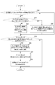
- FIG. 6 is a flowchart showing an operation flow in icon composition processing by the display device according to the first embodiment; 6 is a flowchart illustrating an operation flow in an instruction receiving process for an icon after composition by the display device according to the first embodiment; It is a figure which shows an example of the icon after a synthesis
- A) And (B) is a figure which shows an example of operation with respect to the icon after a synthesis
- 10 is a flowchart illustrating an operation flow in an instruction receiving process for an icon after composition by the display device according to the second embodiment
- 10 is a flowchart showing an operation flow in an instruction receiving process for an icon after composition by a display device according to a third embodiment
- (A) And (B) is a figure which shows an example of the execution screen displayed on a display part, when a mail function and a browser function are performed. It is a perspective view which shows the display apparatus concerning Embodiment 4.
- FIG. It is a figure which shows an example of the operation screen displayed on a display surface.
- FIG. 10 is a diagram illustrating an example of an operation screen displayed on a display surface in a display device according to a fifth embodiment.
- FIG. 1 is a perspective view showing an appearance of a display device according to Embodiment 1 of the present invention.
- FIG. 2 is a block diagram illustrating an internal configuration of the display device according to the first embodiment of the present invention.
- a display device 1 is, for example, a portable mobile device such as a smartphone, and includes a display unit 10, a touch panel unit 20, a communication unit 30, a tilt detection unit 40, and a storage unit 50.
- the control unit 100 is provided. Each of these components can transmit / receive data or signals to / from each other via a CPU bus.
- the display unit 10 includes a liquid crystal display (LCD: Liquid Crystal Display) and an organic EL (OLED: Organic Light-Emitting Diode). As shown in FIG. 1, the display unit 10 displays an operation screen D1 on which a plurality of icons A1 to A9 are arranged. Each of the icons A1 to A9 is associated with various predetermined functions provided in the display device 1, and an image showing the associated functions is drawn. For example, the icon A1 is associated with the mail function. The icon A2 is associated with the Internet browser function.
- LCD Liquid Crystal Display
- OLED Organic Light-Emitting Diode
- the touch panel unit 20 is a so-called resistive film type or capacitive type touch panel.
- the touch panel unit 20 is disposed on the front surface of the display unit 10 and detects contact by the user on the operation screen displayed by the display unit 10 together with the contact position.
- the touch panel unit 20 detects contact by the user, the touch panel unit 20 outputs a detection signal indicating the coordinate position of the contact point to a receiving unit 102 described later of the control unit 100.
- the touch panel unit 20 serves as an operation unit to which a user operation on the operation screen displayed on the display unit 10 is input.
- the touch panel unit 20 includes a touch panel that detects a finger or the like when a user's finger or the like approaches a certain distance from the operation screen without direct contact with the operation screen.
- the “contact” in the present embodiment substantially includes a state in which the function of the touch panel unit 20 detects that a finger or the like has approached the predetermined distance without touching the operation screen. Shall be included.
- the display device 1 may include a physical key in addition to the touch panel unit 20 as an operation unit to which a user operation is input.
- the physical keys include, for example, an arrow key, a page up key, and a page ⁇ ⁇ down key.
- the communication unit 30 is a communication interface including a communication module such as a LAN chip (not shown).
- the display device 1 is connected to another information processing device such as a PC (Personal Computer) via a network, and transmits / receives data to / from the PC connected by the communication unit 30.
- PC Personal Computer
- the tilt detection unit 40 is a so-called gyro sensor, and detects the tilt of the display unit 10. When the tilt detection unit 40 detects the tilt of the display unit 10, the tilt detection unit 40 outputs a detection signal indicating the detected tilt to the display control unit 103 described later of the control unit 100.
- the storage unit 50 is a large-capacity storage device such as an HDD (Hard Disk Drive).
- HDD Hard Disk Drive
- the control unit 100 includes a CPU (Central Processing Unit), a RAM (Random Access Memory), a ROM (Read Only Memory), and the like.
- the control unit 100 functions as the control unit 101, the reception unit 102, the display control unit 103, and the communication control unit 104 when the display control program stored in the ROM or the storage unit 50 is executed by the CPU. To do.
- each said structure of the control unit 100 may be comprised by a hard circuit, respectively, not based on the operation
- the control unit 101 controls the overall operation of the display device 1.
- the control unit 101 is connected to the display unit 10, the touch panel unit 20, the communication unit 30, the tilt detection unit 40, the storage unit 50, and the like. Sends or receives signals or data.
- the control unit 101 particularly serves as a processing unit that executes processing according to an operation received by the receiving unit 102 described below. For example, when an operation for selecting the icon A1 illustrated in FIG. 1 is input by the user using the touch panel function and the reception unit 102 receives a touch operation (also referred to as a selection operation) of the icon A1, the control unit 101 displays the icon The mail function associated with A1 is executed. Specifically, the control unit 101 executes a mail program stored in the storage unit 50 or the like.
- the reception unit 102 specifies a user operation input by the user based on the detection signal output from the touch panel unit 20.
- the receiving unit 102 receives the specified user operation and outputs a control signal corresponding to the user operation to the control unit 101, the display control unit 103, the communication control unit 104, and the like.
- user operations include touch operation, slide operation (including flick operation and swipe operation), drag operation, pinch-out operation, and pinch-in operation.
- touch panel unit 20 when the user makes a finger contact on the touch panel unit 20 and then releases the finger from the contact position, the touch panel unit 20 outputs a detection signal indicating the position where the contact is detected to the receiving unit 102.
- the receiving unit 102 receives the detection signal, specifies that the user operation input by the user is a touch operation, and receives the touch operation.
- the touch panel unit 20 detects each moving position from the initial position at which contact is first detected to the last position at which contact is finally detected. The signal is output to the receiving unit 102.
- the receiving unit 102 receives the detection signal, specifies that the user operation input by the user is a slide operation, and receives the slide operation.
- the communication control unit 104 has a function of controlling the communication operation by the communication unit 30.
- the display control unit 103 has a function of controlling the display operation by the display unit 10.
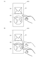
- the display control unit 103 performs a process of changing (enlarging or reducing) the shapes of the icons A1 to A9 arranged on the operation screen D1. Specifically, when the receiving unit 102 receives a pinch-out operation for any one of the icons A1 to A9, the display control unit 103 specifies the shape of the icon for which the pinch-out operation has been performed by the pinch-out operation. It expands to the size. In the example illustrated in FIG. 3, a pinch-out operation directed in the vertical direction on the paper surface is input to the icon A1.
- the display control unit 103 enlarges (extends) the icon A1 in the vertical direction on the paper surface, and causes the display unit 10 to display the enlarged icon A1.
- the display control unit 103 by enlarging the icon A1, the interval between the icon A1 and the icon A2 adjacent to the icon A1 is narrowed, and as a result, the arrangement position of the icon A1 and the arrangement position of the icon A2 are overlapped.
- the display control unit 103 generates a combined icon A10 by superimposing the icon A1 and the icon A2, and displays the combined icon A10 on the display unit 10.
- the storage unit 50 stores in advance a plurality of stepwise values indicating the intervals between adjacent icons that allow the icon arrangement.
- the display control unit 103 refers to the value stored in the storage unit 50 and determines the arrangement position of the enlarged icon. Specifically, when the interval between the enlarged icon and the adjacent icon changes, the display control unit 103 selects one from a plurality of step values stored in the storage unit 50 according to the changed interval. Select a value. Then, the display control unit 103 determines the arrangement position of the enlarged icon so that the interval between the enlarged icon and the adjacent icon becomes the value after selection. Further, the display control unit 103 adjusts the size of the enlarged icon so that the interval between the enlarged icon and the adjacent icon becomes the value after selection.
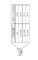
- FIG. 5 is a diagram illustrating an example of the stepwise values stored in advance in the storage unit 50.
- FIG. 6A is a diagram showing an interval between the icon A1 and the icon A2 at the initial arrangement position, and FIGS. 6B to 6F show that the icon A1 is enlarged by a pinch-out operation. It is a figure which shows a mode that the display control part 103 correct
- the upper row shows the interval between icons specified by the pinch-out operation, and the lower row shows after correction of the icons corrected by the display control unit 103. Indicates the interval.
- the storage unit 50 shows the range of the interval between icons corresponding to each of the above stepwise values.
- the display control unit 103 determines which range of the plurality of ranges the interval between icons specified by the pinch-out operation belongs. Then, the display control unit 103 selects a value associated with the determined range from a plurality of stepwise values stored in the storage unit 50.
- the pinch-out operation is input to the icon A1, and the icon A1 is enlarged.
- the interval between the icon A1 and the icon A2 is changed from L1 to L2.
- the display control unit 103 determines the arrangement position of the icon A1 so that the interval between the icon A1 and the icon A2 becomes the length N1 (see the lower part of FIG. 6B).
- the display control unit 103 adjusts the size of the enlarged icon so that the interval between the enlarged icon and the adjacent icon becomes the value after selection (see the lower part of FIG. 6B).
- the interval between the corrected icons is a length N2. Since the length N2 is a value smaller than 0, in this case, an overlap occurs in the icon arrangement position.
- the display control unit 103 generates a combined icon A10 by superimposing the icon A1 and the icon A2 (see the lower part of FIG. 6C).
- the interval between the icon A1 and the icon A2 is further reduced from L3 and changes to L4 and L5 (see the upper part of FIG. 6D and the upper part of FIG. 6E), the intervals L4 and L5 have the length M1. Since it is less than or equal to the length M2, the interval between the corrected icons is the length N2. As described above, even when the interval and the size of the icons specified by the pinch-out operation are different, the display is performed as shown in the lower part of each drawing in FIGS. 6C to 6E. As a result of correction by the control unit 103, the interval between icons and the size of the icons may be the same.
- the interval between the icon A1 and the icon A2 is further reduced from L5 to L6, the interval L6 is less than the length M2 and longer than the length M3. As shown in FIG. 4, the interval between the corrected icons is the length N3.
- the icons are overlapped to generate a combined icon. It becomes one of a plurality of predetermined step values.
- the overlapping state of the icons in the combined icons is allowed without limitation, the appearance of the operation screen on which the icons are arranged becomes complicated, and the visibility of the operation screen and the icons may be reduced.
- the display device according to the first embodiment of the present invention since the overlapping state of the combined icon is limited to a plurality of predetermined patterns, the appearance of the operation screen on which the combined icon is arranged is displayed. The visibility of the operation screen and icons can be made difficult to be reduced.
- the display control unit 103 determines which range of the plurality of ranges stored in the storage unit 50 the interval between icons belongs to, and corrects the value associated with the determined range. Although the case of selecting the interval between the icons has been described, the present invention is not necessarily limited to this case. The display control unit 103 may select a value closest to the changed icon interval among the plurality of stepwise values stored in the storage unit 50 as the corrected icon interval.
- the display control unit 103 performs a process of changing the arrangement position of the icons A1 to A9 from the start point position in the drag operation to the end point position in the drag operation. .
- the display control unit 103 performs a plurality of stepwise steps stored in the storage unit 50 according to the changed interval, as described above. One value is selected from the values, and the arrangement position of the icon after movement is determined so that the distance between the icon after movement and the adjacent icon becomes the value after selection.
- the display control unit 103 generates a combined icon by overlapping the icons.
- the display control unit 103 When the receiving unit 102 receives a pinch-in operation on any of the icons A1 to A9, the display control unit 103 further reduces the shape of the icon that has been subjected to the pinch-in operation to a size specified by the pinch-in operation.
- FIG. 7 is a diagram showing the icon A10 after synthesis.
- the combined icon A10 includes a first area S1 and a second area S2, which are areas in which the arrangement positions of the icons A1 and A2 do not overlap, and the icons A1 and A2.
- the third region S3 is an area where the arrangement positions overlap with each other.
- An image indicating a function associated with the icon A1 is displayed in the first area S1, and an image indicating a function associated with the icon A2 is displayed in the second area S2.
- a composite image generated in accordance with both the image indicating the function associated with the icon A1 and the image indicating the function associated with the icon A2 is displayed.
- the display control unit 103 converts the image indicated by the icon A1 into a translucent image, and the other icon, that is, the image indicated by the icon A2 is seen through the translucent image.
- Such an image is generated as the composite image.
- the user sees the image showing the function associated with the icon A1 through the image showing the function associated with the icon A1 (see the dotted line shown in FIG. 7).
- the display control unit 103 determines the overlapping order of icons when overlapping occurs at the icon arrangement position and a combined icon is generated.
- the display control unit 103 sets the overlapping order of the enlarged icons to the highest order when the icon arrangement position overlaps due to the expansion of the icons.
- the icon A1 is enlarged, and as a result, the icon A2 overlaps. Therefore, the overlapping order of the icons A1 is higher than the overlapping order of the icons A2.
- the display control unit 103 converts the image indicated by the icon A1 into a translucent image, and synthesizes an image in which the image indicated by the icon A2 is visible through the image of the translucent icon A1.
- the image is displayed on the display unit 10 as an image.
- the display control unit 103 converts the image indicated by the icon A2 into a translucent image, and the image indicated by the icon A1 is a translucent icon. An image that is visible through the A2 image is displayed on the display unit 10 as a composite image.
- the display control unit 103 sets the order of overlapping of the moved icons to the highest order.
- the control unit 101 executes a function associated with the icon indicated in the area. Specifically, when the receiving unit 102 receives a touch operation on the first area S1, the control unit 101 executes a mail function that is a function associated with the icon A1 shown in the first area S1. . Moreover, the control part 101 performs the browser function which is a function linked
- the control unit 101 when the reception unit 102 receives an operation of selecting the third region S3 where the icon A1 and the icon A2 overlap, the control unit 101 is associated with each icon superimposed on the third region S3.
- the function associated with the icon having the highest overlapping order is executed. That is, the control unit 101 executes a function associated with an icon indicated by an image displayed in a semi-transparent manner on the display unit 10. In the example shown in FIG. 8A, since the overlapping order of the icons A1 is higher than the overlapping order of the icons A2, the control unit 101 executes a mail function that is a function associated with the icon A1.
- the function executed by the control unit 101 changes depending on the direction in which the touched finger is slid thereafter.
- the user moves his / her finger to the second region S2 (slide operation) in a state where the user touches the third region S3.
- the control unit 101 executes a function associated with the icon A2, which is an icon shown at the end point in the slide operation, that is, a browser function.
- the finger is moved to the second region S2 while the user is in contact with the third region S3.
- the control unit 101 executes a function associated with the icon A1, which is an icon shown at the end point in the slide operation, that is, a mail function.
- a function associated with the icon A1 which is an icon shown at the end point in the slide operation, that is, a mail function.
- the receiving unit 102 receives a slide operation starting from one point of the third region S3 where the icons overlap in the combined icon A10, the control unit 101 overlaps the third region S3.
- the function associated with the icon indicated at the end point in the slide operation is executed.
- the display control unit 103 displays the icon A2 shown in the second area S2.
- the overlapping order is set to the highest order, and the display in the third region S3 is changed (see FIG. 9B).
- the display control unit 103 converts the image indicated by the icon A2 into a translucent image so that the image indicated by the icon A1 is visible through the image indicated by the translucent icon A2.
- the composite image is updated, and a composite icon including the composite image after the update is displayed on the display unit 10.
- the display control unit 103 displays the icon indicated as the end point in the slide operation.
- the overlapping order is changed to the highest order, the icons are superimposed according to the changed overlapping order to generate a combined icon, and the combined icon is displayed on the display unit 10.
- FIG. 10 is a flowchart showing the flow of operations in the icon composition processing by the display device 1.
- the reception unit 102 receives a pinch-out operation for an icon (YES in step S10)
- the display control unit 103 specifies the size of the enlarged icon specified by the pinch-out operation (step S11).
- the display control unit 103 calculates an interval between the enlarged icon and the adjacent icon (step S12).
- the display control unit 103 selects one value as a corrected icon interval from a plurality of stepwise values stored in the storage unit 50 based on the calculated icon interval (step S13). ). Then, the display control unit 103 performs a process for determining the arrangement position of the enlarged icon (step S14) and a process for adjusting the size of the enlarged icon (step S15) based on the selected value.
- step S14 and step S15 when the arrangement position of the enlarged icon and the adjacent icon is overlapped (YES in step S16), the display control unit 103 determines whether the enlarged icon is adjacent to the adjacent icon. The overlapping order is determined (step S17), and a combined icon is generated by superimposing the enlarged icon and the adjacent icon based on the determined overlapping order (step S18). Then, the display control unit 103 causes the display unit 10 to display an operation screen on which the generated combined icon is arranged (step S19).
- the display control unit 103 causes the display unit 10 to display an operation screen in which the enlarged icon is arranged ( Step S20).
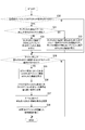
- FIG. 11 is a flowchart showing an operation flow in the instruction receiving process for the combined icon by the display device 1.
- the reception unit 102 receives a touch operation on the combined icon (YES in step S30) and the touched region is a region where the icons are not overlapped (NO in step S31)
- the control unit 101 performs the touch.
- the function associated with the icon shown in the designated area is executed (step S32).
- the control unit 101 determines that the overlapping of the functions associated with the icons superimposed on the touched area.
- the function associated with the icon having the highest order, that is, the icon displayed in a semi-transparent state is executed (step S33).
- step S34 When the accepting unit 102 accepts a slide operation starting from an area where the icons are superimposed on the combined icon (YES in step S34), the control unit 101 is associated with the icon indicated as the end point in the slide operation. The function is executed (step S35). Then, the display control unit 103 changes the overlapping order of the icons shown at the end point in the slide operation to the highest order (step S36), and displays the area where the icons are overlapped based on the changed overlapping order. Is changed (step S37). After the process of step S37, the display control unit 103 causes the display unit 10 to display an operation screen on which the changed icon is arranged (step S38).
- the display device 1 when an icon arrangement position is overlapped, it is possible to generate a combined icon and accept an operation on the combined icon from the user. It becomes. Moreover, the process which the display apparatus 1 performs among the several processes linked
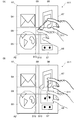
- the combined icon A11 includes the first region S4, the second region S5, the third region S6, the fourth region S7, and the icons that are not overlapped with each other.
- the region is composed of nine regions, namely, a fifth region S8, a sixth region S9, a seventh region S10, an eighth region S11, and a ninth region S12.
- the fifth area S8 is an area in which the icon A1 and the icon A2 are overlapped
- the sixth area S9 is an area in which the icon A1 and the icon A7 are overlapped
- the seventh area S10 is an icon.
- A8 is an area where the icon A8 is overlapped
- the eighth area S11 is an area where the icon A7 and the icon A8 are overlapped
- the ninth area S12 is an icon A1, the icon A2, and the icon A7. This is a region where the icon A8 is overlapped.
- the control unit 101 executes a function associated with the icon A7 that is an icon shown at the end point in the slide operation.
- the finger is moved to the third region S6 in a state where the user touches the eighth region S11. Also at this time, the control unit 101 executes a function associated with the icon A7 which is an icon shown at the end point in the slide operation.
- FIG. 14 is a flowchart illustrating an operation flow in an instruction receiving process for an icon after composition by the display device 1 according to the second embodiment. Note that processes having the same contents as those shown in the flowchart of FIG. 11 are denoted by the same reference numerals, and description thereof is omitted or simplified.
- step S30 When the reception unit 102 receives a touch operation on the combined icon (YES in step S30) and the touched region is a region where the icons are not overlapped (NO in step S31), the control unit 101 performs the touch.
- the function associated with the icon shown in the designated area is executed (step S32).
- control unit 101 executes each of the functions associated with each icon overlapped with the touched area. (Step S40). As shown in FIG. 8A, when the accepting unit 102 accepts a touch operation on the third region S3, the control unit 101 performs a mail function associated with the icon A1 superimposed on the third region S3. And the browser function associated with icon A2.
- step S34 When the receiving unit 102 receives a slide operation starting from an area where the icons are superimposed on the combined icon (YES in step S34), the display control unit 103 performs the process of step S35 described in the first embodiment. Without changing, the order of overlap of the icons shown at the end point in the slide operation is changed to the highest order (step S36), and the display of the region where the icons are overlapped is changed based on the changed order of overlap. (Step S37). After the process of step S37, the display control unit 103 causes the display unit 10 to display an operation screen on which the changed icon is arranged (step S38).
- each process associated with the icon superimposed on the third region S3 is performed by the touch operation on the third region S3 on which the icon is superimposed. 1 can be executed.
- FIG. 15 is a flowchart illustrating an operation flow in the instruction receiving process for the combined icon by the display device 1 according to the third embodiment. Note that processes having the same contents as those shown in the flowchart of FIG. 11 are denoted by the same reference numerals, and description thereof is omitted or simplified.
- step S30 When the reception unit 102 receives a touch operation on the combined icon (YES in step S30) and the touched region is a region where the icons are not overlapped (NO in step S31), the control unit 101 performs the touch.
- the function associated with the icon shown in the designated area is executed (step S32).
- the control unit 101 determines that the overlapping of the functions associated with the icons superimposed on the touched area.
- the function associated with the icon with the highest order is executed (step S50).
- the control part 101 performs the function linked
- the control unit 101 when the accepting unit 102 accepts a touch operation on the third region S3, the control unit 101 performs a mail function associated with the icon A1 superimposed on the third region S3. And the mail function associated with the icon A1, which is the icon with the highest overlapping order among the browser functions associated with the icon A2, is first executed. And the control part 101 performs the browser function linked
- the control unit 101 displays the size of a screen (window) displayed on the display unit 10 when a function with a low priority is executed, and is displayed on the display unit 10 when a function with a higher priority is executed. Make the size smaller than the screen size.
- the control unit 101 displays an execution screen D3 displayed on the display unit 10 when the browser function is executed, as shown in FIG.
- the size is smaller than the execution screen D2 displayed on the display unit 10 (size T2 ⁇ size T1).
- control unit 101 may execute a function with a higher priority in the foreground and a function with a lower priority than that in the background.
- control unit 101 may allocate a large processing capacity of the CPU when executing a function with a high priority, and may allocate a small processing capacity of the CPU when executing a function with a lower priority than that.
- step S ⁇ b> 34 when the accepting unit 102 accepts a slide operation starting from a region where the icons are superimposed on the combined icon (YES in step S ⁇ b> 34), the display control unit 103 performs the process of step S ⁇ b> 34.
- the priority is determined based on the slide operation received by the receiving unit 102 (step S52). Specifically, the display control unit 103 sets the priority of the function associated with the icon indicated at the end point in the slide operation to the priority of the function associated with another icon superimposed on the start point in the slide operation. Decide high.
- control unit 101 executes each function associated with each icon superimposed on the start point in the slide operation with the priority determined in the process of step S52 (step S53).
- the control unit 101 displays the mail function associated with the icon A1 superimposed on the third area S3 and the browser associated with the icon A2.
- the browser function associated with the icon A2 shown at the end point of the slide operation is executed with a higher priority than the mail function.
- step S53 the overlapping order of the icons shown at the end points in the slide operation is changed to the highest order (step S36), and based on the changed overlapping order.
- step S37 The display of the area where the icons are overlapped is changed (step S37).
- step S38 the display control unit 103 causes the display unit 10 to display an operation screen on which the changed icon is arranged (step S38).
- the display device 1 According to the display device 1 according to the third embodiment, among the plurality of processes associated with the icon superimposed on the third region S3 by the slide operation on the third region S3 on which the icon is superimposed. Therefore, it is possible to select a process to be executed with priority by the display device 1.
- the control unit 101 may determine the priority according to the slide speed in the slide operation.
- the control unit 101 sets a higher priority when executing the process than when the slide speed is low.
- the user can select not only the process that the display device 1 executes with priority, but also how much the process is prioritized.
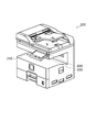
- FIG. 17 is a perspective view of the display device according to the fourth embodiment.
- a display device 210 according to the fourth embodiment is arranged on the front surface of an image forming apparatus 200 that is a multifunction machine having a plurality of functions such as a facsimile communication function, a copy function, a printer function, and a scanner function, with a rotation shaft 230 as a center. It is provided so as to be rotatable in the direction of the arrow in FIG. As the display device 210 rotates, the inclination of the display surface 220 with respect to the horizontal direction is changed.
- FIG. 18 is a diagram illustrating an example of an operation screen displayed on the display surface 220.
- a plurality of icons A21 to A28 are arranged on the operation screen D4.
- Each of the icons A21 to A28 has a substantially square shape in which the vertical length U1 and the horizontal length U2 are equal.
- FIG. 19A is a diagram showing an operation screen D4 visually recognized by the user when viewing the display surface 220 from the front.
- the icons A21 to A28 have an apparently square shape, and the original square shape is maintained.
- the apparent vertical length of the icon A21 is U3
- the apparent horizontal length is U4
- an operation screen D4 as shown in FIG. 19B is visually recognized by the user. Since the display surface 220 is inclined in the upward direction on the paper surface, the icons A21 to A28 are visually recognized by the user as if they contracted in the upward direction on the paper surface as shown in the figure. As a result, the icons A21 to A28 have an apparently rectangular shape whose vertical length is shorter than the horizontal length. That is, the apparent shapes of the icons A21 to A28 are broken from the original substantially square shape.
- the apparent vertical length of the icon A21 is U5, the apparent vertical length is U6, and the vertical length U5 is shorter than the horizontal length U6 (U5 ⁇ U6).
- the apparent shape of the icons A21 to A28 collapses from the substantially square shape, which is the original shape, so that the visibility of the icons A21 to A28 is lowered.
- the display control unit 103 causes the display device 210 to display each of the icons A21 to A28 in a display form expanded in the first direction (upward on the paper surface).
- the first direction is a direction on the operation screen that moves away from the user's line of sight when the inclination of the display surface 220 is changed in one direction.
- the display control unit 103 has two display modes, a normal display mode and a correction display mode, as display modes for displaying the icons A21 to A28.
- the normal display mode is a display mode in which the icons A21 to A28 included in the operation screen D4 are displayed on the display device 210 in a normal display form.
- the normal display form is a display form in which an image stored in the storage unit in advance as an image showing the icons A21 to A28 is displayed on the display device 210 as it is.
- the storage unit stores substantially square icons A21 to A28 having the same vertical length and horizontal length.
- the correction display mode is a display mode in which the icons A21 to A28 stored in the storage unit are expanded in the upward direction on the paper surface and the expanded icon is displayed on the display device 210.
- display mode the display control unit 103 displays an icon on the display device 210 is selectively determined according to a user operation input to a predetermined reception screen displayed on the display device 210.
- the display mode may transition from the normal display mode to the corrected display mode.
- the operation screen D4 As shown in FIG.
- the operation screen D4 is viewed from an oblique direction
- the operation screen D4 as shown in FIG. 19B is viewed by the user.
- an operation screen as shown in FIG. 20 is displayed on the display surface 220.
- icons A21 to A28 are arranged in which each of the icons extends in the upward direction on the paper surface.
- the icons A21 to A28 are substantially rectangular in which the vertical length is longer than the horizontal length.
- the vertical length of the icon A21 is U7 (U7> U1)
- the vertical length U7 is longer than the horizontal length U8 ( U7> U8).
- the operation screen D5 as shown in FIG. 21 is visually recognized by the user. Since the display surface 220 is inclined in the upward direction on the paper surface, the icons A21 to A28 are visually recognized by the user as if they contracted in the upward direction on the paper surface. As a result, the icons A21 to A28 have a shorter apparent vertical length. For example, the apparent vertical length of the icon A21 is U9, and the apparent vertical length is U10.
- the ratio between the apparent vertical length U5 and horizontal length U6 of the pre-extension icon A21 is compared with the ratio (aspect ratio) of the apparent vertical length U9 and the horizontal length U10 of the expanded icon A21 to the apparent aspect ratio of the expanded icon A21. Is closer to “1”. That is, the apparent shape of the icon A21 after expansion is closer to a substantially square shape than the apparent shape of the icon A21 before expansion.
- the apparent shapes of the icons A21 to A28 after expansion are not substantially square shapes, they are substantially square shapes that are the original shapes rather than the apparent shapes of the icons A21 to A28 before expansion.
- the shape is close to. For this reason, even when the user visually recognizes the operation screen displayed on the display surface 220 from an oblique direction by changing the inclination of the display surface 220, the visibility of the icons arranged on the operation screen is hardly lowered. be able to.
- the display control unit 103 when the display control unit 103 extends the icons A21 to A28, adjacent icons may overlap each other. In the example shown in FIG. 22, since the interval between icons arranged on the operation screen D7 is narrow, the icons are overlapped when the display control unit 103 extends the icons in the upward direction on the paper surface. In this case, as described in the first to third embodiments, the display control unit 103 superimposes icons to generate a composite icon. As a result, when there is an overlap in the arrangement position of the icons according to the tilt of the display surface 220, it is possible to generate a combined icon and accept an operation on the combined icon from the user. In addition, by performing a slide operation on an area where icons are superimposed, a process to be executed by the display device 210 can be selected from among a plurality of processes associated with the icon superimposed on the area.
- the display control unit 103 expands the icon included in the operation screen not only in the first direction but also in the second direction orthogonal to the first direction. Moreover, the display control part 103 lengthens the length extended toward a 2nd direction as it approaches a 1st direction side.
- FIG. 23 is a diagram illustrating a state in which the operation screen in which the icon is expanded is viewed from an oblique direction in the display device according to the fourth embodiment.
- the icon included in the operation screen is visually recognized small.
- the apparent upper side length U11 of the icon A21 is shorter than the apparent lower side length U12 of the icon A21. This is because the distance between the upper side of the icon A21 and the user's eyes is longer than the distance between the lower side of the icon A21 and the user's eyes. As a result, the icon A21 has a trapezoidal appearance. Similarly, the other icons A22 to A28 have a trapezoidal appearance. As described above, the icons A21 to A28 arranged on the operation screen D4 have a shape different from the substantially square which is the original shape, so that the visibility of the icons A21 to A28 is lowered.
- the display control unit 103 sets each of the icons A21 to A28 not only in the first direction (upward direction in the drawing) but also in the first direction orthogonal to the first direction. Extends in two directions (left and right on the page). Further, the display control unit 103 increases the length of extending the icon in the second direction as it approaches the first direction side (upward direction on the paper surface).
- FIG. 24 is a diagram illustrating an example of an operation screen displayed on the display surface 220 by the display control unit 103. In the example shown in this figure, on the operation screen D6, expanded icons A21 to A28 that are further expanded in the horizontal direction on the paper are arranged for the icons that are expanded in the upward direction on the paper.
- the icons A21 to A28 have an inverted trapezoidal shape whose upper side is longer than the lower side.
- the length of the upper side is U13
- the length of the lower side is U14
- the length U13 of the upper side is longer than the length U14 of the lower side (U13> U14).
- the apparent shape of the icon included in the operation screen is close to the original shape (substantially square) even when the user views the operation screen from an angle. can do.
- the display control unit 103 when the display control unit 103 extends the icons A21 to A28 in the first direction and the second direction so that adjacent icons overlap each other, the display control unit 103 As described in the first to third embodiments, the icons are overlapped to generate a composite icon.
- the display device according to each embodiment can be applied to a display device provided in a PC (Personal Computer), a television, or the like, in addition to a mobile terminal such as a smartphone or an image forming apparatus.
- a PC Personal Computer
- a television or the like
- a mobile terminal such as a smartphone or an image forming apparatus.
- the present invention is not necessarily limited to this case.
- the shape of the icon included in the operation screen is not particularly limited.
- the icon may be a substantially circular shape.
- the display control program described in the above embodiment may be recorded on a computer-readable non-transitory recording medium such as a hard disk, CD-ROM, DVD-ROM, or semiconductor memory.
- a computer-readable non-transitory recording medium that records the control program is an embodiment of the present invention.
Landscapes
- Engineering & Computer Science (AREA)
- General Engineering & Computer Science (AREA)
- Theoretical Computer Science (AREA)
- Human Computer Interaction (AREA)
- Physics & Mathematics (AREA)
- General Physics & Mathematics (AREA)
- User Interface Of Digital Computer (AREA)
Abstract
Description
図1は、本発明の実施形態1にかかる表示装置の外観を示す斜視図である。図2は、本発明の実施形態1にかかる表示装置の内部構成を示すブロック図である。 <
FIG. 1 is a perspective view showing an appearance of a display device according to
上記では、2つのアイコンの配置位置に重なりが生じ、表示制御部103が2つのアイコンを合成する場合を説明したが、本発明は必ずしもこの場合に限定されない。3以上のアイコンの配置位置に重なりが生じた場合には、表示制御部103は、当該3以上のアイコンを合成してもよい。 <Supplement>
In the above description, a case has been described in which the two icons are overlapped and the
実施形態2にかかる表示装置1では、合成後のアイコンにおいてアイコンが重なり合った領域の一点を選択する操作を受付部102が受け付けた場合、表示制御部103が当該領域に重ね合わされた各アイコンに関連付けられた各機能をそれぞれ実行する。 <Embodiment 2>
In the
実施形態3にかかる表示装置1では、合成後のアイコンにおいてアイコンが重なり合った領域の一点を始点としたスライド操作を受付部102が受け付けた場合、当該領域に重ね合わされた各アイコンに関連付けられた各機能のうち、スライド操作における終点に示される第1のアイコンに関連付けられた機能を実行し、第1のアイコン以外の第2のアイコンに関連付けられた機能を第1のアイコンに関連付けられた機能よりも低い優先度で実行する。 <Embodiment 3>
In the
上記の実施の形態では、受付部102がアイコンに対するピンチアウト操作を受け付けた場合に、表示制御部103がアイコンを拡大する場合を説明した。これに対して、実施形態4にかかる表示装置では、表示部の表示面の傾きに応じて、表示制御部103がアイコンのサイズを変更する。 <Embodiment 4>
In the above embodiment, a case has been described in which the
実施形態5にかかる表示装置では、表示制御部103が、第一方向だけでなく、当該第一方向に直交する第二方向に向けて、操作画面に含まれるアイコンを伸長する。また、表示制御部103は、第二方向に向けて伸長する長さを第一方向側に近づくにつれて長くする。 <Embodiment 5>
In the display device according to the fifth embodiment, the
Claims (15)
- 予め定められた機能が関連付けられるとともに当該関連付けられた機能を示す画像が示された複数のアイコンが配置された操作画面を表示する表示部と、
前記表示部による表示動作を制御する表示制御部と、
前記操作画面に対する操作を受け付ける受付部と、
前記受付部が受け付けた操作に応じた処理を実行する処理部とを備え、
前記表示制御部は、(i)前記アイコンに対する予め定められた操作を前記受付部が受け付けた場合に、前記アイコンを拡大し、(ii)当該アイコンの拡大により少なくとも2つのアイコンの配置位置に重なりが生じた場合に、当該配置位置に重なりが生じていない第1の領域と当該配置位置に重なりが生じた第2の領域とから構成され、当該第2の領域に前記少なくとも2つのアイコンに示される複数の画像に応じて生成した合成画像を示した合成アイコンを生成し、(iii)当該生成した合成アイコンを前記表示部に表示させ、
前記処理部は、(i)前記合成アイコンにおいて前記第1の領域の一点を選択する操作を前記受付部が受け付けた場合、前記第1の領域に示されるアイコンに関連付けられた機能を実行する処理を行い、(ii)前記合成アイコンにおいて前記第2の領域の一点を始点としたスライド操作を前記受付部が受け付けた場合、前記少なくとも2つのアイコンのそれぞれに関連付けられた各機能のうち、前記スライド操作における終点に示されるアイコンに関連付けられた機能を実行する、表示装置。 A display unit for displaying an operation screen in which a plurality of icons in which images indicating the associated functions are displayed and associated with a predetermined function are arranged;
A display control unit for controlling a display operation by the display unit;
A reception unit that receives an operation on the operation screen;
A processing unit that executes processing according to the operation received by the receiving unit,
The display control unit (i) enlarges the icon when the receiving unit accepts a predetermined operation on the icon, and (ii) overlaps an arrangement position of at least two icons by the enlargement of the icon. Is formed from a first area where the arrangement position does not overlap and a second area where the arrangement position overlaps, and the second area is indicated by the at least two icons. Generating a composite icon indicating a composite image generated according to a plurality of images, and (iii) displaying the generated composite icon on the display unit,
The processing unit (i) a process of executing a function associated with the icon indicated in the first area when the receiving unit receives an operation of selecting one point of the first area in the composite icon (Ii) When the reception unit receives a slide operation starting from one point of the second area in the composite icon, among the functions associated with each of the at least two icons, the slide A display device that performs a function associated with an icon indicated at an end point in an operation. - 前記表示制御部は、前記少なくとも2つのアイコンのうち、1つのアイコンに示される画像を半透明の画像に変換し、それ以外のアイコンに示される画像が前記半透明の画像を透過して視認される画像を前記合成画像として生成する、請求項1に記載の表示装置。 The display control unit converts an image indicated by one of the at least two icons into a translucent image, and images indicated by other icons are visually recognized through the translucent image. The display device according to claim 1, wherein an image to be generated is generated as the composite image.
- 前記処理部は、前記合成アイコンにおいて前記第2の領域の一点を選択する操作を前記受付部が受け付けた場合、前記少なくとも2つのアイコンのそれぞれに関連付けられた各機能のうち、前記半透明の画像が示すアイコンに関連付けられた機能を実行する、請求項2に記載の表示装置。 When the accepting unit accepts an operation of selecting one point of the second region in the composite icon, the processing unit includes the translucent image among the functions associated with each of the at least two icons. The display device according to claim 2, wherein the display device executes a function associated with the icon indicated by.
- 前記表示制御部は、前記合成アイコンにおいて前記第2の領域の一点を始点としたスライド操作を前記受付部が受け付けた場合、前記少なくとも2つのアイコンのうち、前記スライド操作における終点に示されるアイコンに示される画像を半透明の画像に変換し、それ以外のアイコンに示される画像が前記半透明の画像を透過して視認されるように前記合成画像を更新し、当該更新後の合成画像を前記第2の領域に示した合成アイコンを前記表示部に表示させる、請求項2に記載の表示装置。 When the receiving unit receives a slide operation starting from one point of the second area in the composite icon, the display control unit is changed to an icon indicated as an end point in the slide operation among the at least two icons. The displayed image is converted into a translucent image, and the composite image is updated so that the image indicated by the other icon is visible through the translucent image, and the updated composite image is The display device according to claim 2, wherein the composite icon shown in the second area is displayed on the display unit.
- 前記表示制御部は、アイコンの拡大により少なくとも2つのアイコンの配置位置に重なりが生じた場合に、当該少なくとも2つのアイコンのうち、前記拡大したアイコンに示される画像を前記半透明の画像に変換して前記合成画像を生成する、請求項2に記載の表示装置。 The display control unit converts an image indicated by the enlarged icon of the at least two icons into the translucent image when at least two icons are overlapped due to the enlargement of the icons. The display device according to claim 2, wherein the composite image is generated.
- 前記処理部は、前記合成アイコンにおいて前記第2の領域の一点を選択する操作を前記受付部が受け付けた場合、前記少なくとも2つのアイコンのそれぞれに関連付けられた各機能をそれぞれ実行する、請求項1に記載の表示装置。 2. The processing unit executes each function associated with each of the at least two icons when the receiving unit receives an operation of selecting one point of the second region in the composite icon. The display device described in 1.
- 前記処理部は、前記合成アイコンにおいて前記第2の領域の一点を始点としたスライド操作を前記受付部が受け付けた場合、前記少なくとも2つのアイコンのそれぞれに関連付けられた各機能のうち、前記スライド操作における終点に示されるアイコンに関連付けられた機能を実行することに加えて、更に、前記第1のアイコン以外の第2のアイコンに関連付けられた機能を前記第1のアイコンに関連付けられた機能よりも低い優先度で実行する、請求項1に記載の表示装置。 When the reception unit receives a slide operation starting from one point of the second area in the composite icon, the processing unit includes the slide operation among the functions associated with each of the at least two icons. In addition to executing the function associated with the icon indicated at the end point in the function, the function associated with the second icon other than the first icon is more than the function associated with the first icon. The display device according to claim 1, wherein the display device is executed with a low priority.
- 前記表示制御部は、前記少なくとも2つのアイコンのうち、1つのアイコンに示される画像を半透明の画像に変換し、それ以外のアイコンに示される画像が前記半透明の画像を透過して視認される画像を前記合成画像として生成し、
前記処理部は、前記合成のアイコンにおいて前記第2の領域の一点を選択する操作を前記受付部が受け付けた場合、前記少なくとも2つのアイコンのそれぞれに関連付けられた各機能のうち、前記半透明の画像が示すアイコンに関連付けられた機能を実行し、それ以外のアイコンに関連付けられた機能を前記半透明の画像が示すアイコンに関連付けられた機能よりも低い優先度で実行する、請求項7に記載の表示装置。 The display control unit converts an image indicated by one of the at least two icons into a translucent image, and images indicated by other icons are visually recognized through the translucent image. Image as the composite image,
When the accepting unit accepts an operation of selecting one point of the second region in the composite icon, the processing unit includes the semi-transparent of each function associated with each of the at least two icons. The function associated with the icon indicated by the image is executed, and the function associated with the other icon is executed with a lower priority than the function associated with the icon indicated by the translucent image. Display device. - 前記処理部は、前記第2のアイコンに関連付けられた機能を実行した際に前記表示部に表示されるウィンドウのサイズを、前記第1のアイコンに関連付けられた機能を実行した際に前記表示部に表示されるウィンドウのサイズよりも小さいサイズにすることを前記低い優先度での機能実行とする、請求項7に記載の表示装置。 The processing unit displays the size of the window displayed on the display unit when the function associated with the second icon is executed, and the display unit when the function associated with the first icon is executed. The display device according to claim 7, wherein the function execution at the low priority is to make the size smaller than the size of the window displayed on the screen.
- 前記処理部は、前記第1のアイコンに関連付けられた機能をフォアグラウンドで実行し、前記第2のアイコンに関連付けられた機能をバックグラウンドで実行することを前記低い優先度での機能実行とする、請求項7に記載の表示装置。 The processing unit executes the function associated with the first icon in the foreground, and executes the function associated with the second icon in the background as the function execution with the low priority. The display device according to claim 7.
- 前記アイコンの配置を許容する隣り合うアイコン同士の間隔を示す複数の段階的な値を予め記憶した記憶部を更に備え、
前記表示制御部は、前記アイコンを拡大することにより拡大後のアイコンと隣り合うアイコンの間隔が変化した場合に、変化後の間隔に応じて前記記憶部に記憶された複数の段階的な値から1つの値を選択し、前記拡大後のアイコンと隣り合うアイコンとの間隔が選択後の値になるように、前記拡大後のアイコンの配置位置を決定し、その結果、前記拡大後のアイコンと前記隣り合うアイコンとの配置位置に重なりが生じた場合に前記合成アイコンを生成する、請求項1に記載の表示装置。 A storage unit preliminarily storing a plurality of step values indicating an interval between adjacent icons allowing the icon arrangement;
When the interval between the icons adjacent to the enlarged icon is changed by enlarging the icon, the display control unit determines from the stepwise values stored in the storage unit according to the changed interval. One value is selected, and an arrangement position of the enlarged icon is determined so that an interval between the enlarged icon and an adjacent icon becomes a value after the selection, and as a result, The display device according to claim 1, wherein the composite icon is generated when an overlap occurs in an arrangement position with the adjacent icon. - 前記表示制御部は、前記記憶部に記憶された複数の段階的な値のうち、変化後の前記アイコンの間隔に最も近い1つの値を選択する、請求項11に記載の表示装置。 The display device according to claim 11, wherein the display control unit selects one value that is closest to the interval between the icons after the change from among a plurality of stepwise values stored in the storage unit.
- 前記受付部は、前記アイコンに対するピンチアウト操作を、前記予め定められた操作として受け付ける、請求項12に記載の表示装置。 The display device according to claim 12, wherein the reception unit receives a pinch-out operation for the icon as the predetermined operation.
- 前記表示部は、その表示面の傾きが変更可能に構成され、
前記表示制御部は、前記表示面の傾きが変更された際にユーザーの視線から遠ざかる前記操作画面上における第一方向に向けて前記アイコンを伸長することで前記アイコンを拡大し、前記アイコンの拡大によりアイコンの配置位置に重なりが生じた場合に、前記合成アイコンを生成する、請求項1に記載の表示装置。 The display unit is configured to change the inclination of the display surface,
The display control unit expands the icon by extending the icon in a first direction on the operation screen away from the user's line of sight when the inclination of the display surface is changed, and enlarges the icon The display device according to claim 1, wherein the composite icon is generated when an overlap occurs at an icon arrangement position. - 前記表示制御部は、更に、前記アイコンを前記第一方向に直交する第二方向に向けて伸長し、その伸長する長さを前記第一方向側に近づくにつれて大きくすることで、前記アイコンを拡大する、請求項14に記載の表示装置。 The display control unit further expands the icon by extending the icon in a second direction orthogonal to the first direction and increasing the extending length toward the first direction. The display device according to claim 14.
Priority Applications (4)
| Application Number | Priority Date | Filing Date | Title |
|---|---|---|---|
| JP2017543517A JP6477905B2 (en) | 2015-09-30 | 2016-09-28 | Display device |
| US15/761,560 US10705698B2 (en) | 2015-09-30 | 2016-09-28 | Executing functions associated with icons having overlapping areas |
| EP16851678.9A EP3358453B1 (en) | 2015-09-30 | 2016-09-28 | Display device |
| CN201680056193.XA CN108139847B (en) | 2015-09-30 | 2016-09-28 | Display device |
Applications Claiming Priority (8)
| Application Number | Priority Date | Filing Date | Title |
|---|---|---|---|
| JP2015194383 | 2015-09-30 | ||
| JP2015194380 | 2015-09-30 | ||
| JP2015194381 | 2015-09-30 | ||
| JP2015-194381 | 2015-09-30 | ||
| JP2015-194383 | 2015-09-30 | ||
| JP2015194382 | 2015-09-30 | ||
| JP2015-194380 | 2015-09-30 | ||
| JP2015-194382 | 2015-09-30 |
Publications (1)
| Publication Number | Publication Date |
|---|---|
| WO2017057507A1 true WO2017057507A1 (en) | 2017-04-06 |
Family
ID=58423969
Family Applications (1)
| Application Number | Title | Priority Date | Filing Date |
|---|---|---|---|
| PCT/JP2016/078708 WO2017057507A1 (en) | 2015-09-30 | 2016-09-28 | Display device |
Country Status (5)
| Country | Link |
|---|---|
| US (1) | US10705698B2 (en) |
| EP (1) | EP3358453B1 (en) |
| JP (1) | JP6477905B2 (en) |
| CN (1) | CN108139847B (en) |
| WO (1) | WO2017057507A1 (en) |
Cited By (1)
| Publication number | Priority date | Publication date | Assignee | Title |
|---|---|---|---|---|
| JP2018190171A (en) * | 2017-05-02 | 2018-11-29 | 京セラドキュメントソリューションズ株式会社 | Display |
Families Citing this family (3)
| Publication number | Priority date | Publication date | Assignee | Title |
|---|---|---|---|---|
| US11334243B2 (en) * | 2018-06-11 | 2022-05-17 | Mitsubishi Electric Corporation | Input control device |
| KR20200050042A (en) * | 2018-10-31 | 2020-05-11 | 엔에이치엔 주식회사 | A method for daptively magnifying graphic user interfaces and a mobile device for performing the same |
| CN111638823B (en) * | 2020-05-27 | 2022-06-10 | 维沃移动通信(杭州)有限公司 | Application icon display method and device and electronic equipment |
Citations (3)
| Publication number | Priority date | Publication date | Assignee | Title |
|---|---|---|---|---|
| WO2014041930A1 (en) * | 2012-09-13 | 2014-03-20 | 株式会社エヌ・ティ・ティ・ドコモ | User inteface device, search method, and program |
| JP2014529820A (en) * | 2011-09-01 | 2014-11-13 | マイクロソフト コーポレーション | Tile array |
| JP2015046042A (en) * | 2013-08-28 | 2015-03-12 | 京セラ株式会社 | Portable terminal, combination control program, and combination control method |
Family Cites Families (11)
| Publication number | Priority date | Publication date | Assignee | Title |
|---|---|---|---|---|
| JP2002261918A (en) * | 2001-03-02 | 2002-09-13 | Hitachi Ltd | Cellular phone |
| JP2003150296A (en) * | 2001-11-14 | 2003-05-23 | Nec Corp | Terminal and information display method and program therefor |
| JP2007060555A (en) * | 2005-08-26 | 2007-03-08 | Canon Inc | Television program display device, display control method, program, and storage medium |
| US20080165390A1 (en) * | 2007-01-08 | 2008-07-10 | Samsung Electronics Co., Ltd. | Image forming device and method to adjust images in document to be printed |
| US8745513B2 (en) * | 2007-11-29 | 2014-06-03 | Sony Corporation | Method and apparatus for use in accessing content |
| JP5264298B2 (en) | 2008-06-04 | 2013-08-14 | キヤノン株式会社 | Image processing apparatus and image processing method |
| US8775957B2 (en) * | 2008-12-01 | 2014-07-08 | Lg Electronics Inc. | Method for operating execution icon of mobile terminal |
| KR20110014040A (en) * | 2009-08-04 | 2011-02-10 | 엘지전자 주식회사 | Mobile terminal and icon collision controlling method thereof |
| KR101271539B1 (en) * | 2011-06-03 | 2013-06-05 | 엘지전자 주식회사 | Mobile terminal and control method thereof |
| US9256349B2 (en) * | 2012-05-09 | 2016-02-09 | Microsoft Technology Licensing, Llc | User-resizable icons |
| KR101598710B1 (en) * | 2014-09-11 | 2016-02-29 | 엘지전자 주식회사 | Mobile terminal and method for controlling the same |
-
2016
- 2016-09-28 EP EP16851678.9A patent/EP3358453B1/en active Active
- 2016-09-28 WO PCT/JP2016/078708 patent/WO2017057507A1/en active Application Filing
- 2016-09-28 JP JP2017543517A patent/JP6477905B2/en not_active Expired - Fee Related
- 2016-09-28 CN CN201680056193.XA patent/CN108139847B/en active Active
- 2016-09-28 US US15/761,560 patent/US10705698B2/en active Active
Patent Citations (3)
| Publication number | Priority date | Publication date | Assignee | Title |
|---|---|---|---|---|
| JP2014529820A (en) * | 2011-09-01 | 2014-11-13 | マイクロソフト コーポレーション | Tile array |
| WO2014041930A1 (en) * | 2012-09-13 | 2014-03-20 | 株式会社エヌ・ティ・ティ・ドコモ | User inteface device, search method, and program |
| JP2015046042A (en) * | 2013-08-28 | 2015-03-12 | 京セラ株式会社 | Portable terminal, combination control program, and combination control method |
Non-Patent Citations (1)
| Title |
|---|
| See also references of EP3358453A4 * |
Cited By (1)
| Publication number | Priority date | Publication date | Assignee | Title |
|---|---|---|---|---|
| JP2018190171A (en) * | 2017-05-02 | 2018-11-29 | 京セラドキュメントソリューションズ株式会社 | Display |
Also Published As
| Publication number | Publication date |
|---|---|
| US10705698B2 (en) | 2020-07-07 |
| CN108139847A (en) | 2018-06-08 |
| EP3358453A4 (en) | 2019-05-01 |
| JP6477905B2 (en) | 2019-03-06 |
| EP3358453B1 (en) | 2020-04-22 |
| CN108139847B (en) | 2021-03-12 |
| EP3358453A1 (en) | 2018-08-08 |
| JPWO2017057507A1 (en) | 2018-07-05 |
| US20180260104A1 (en) | 2018-09-13 |
Similar Documents
| Publication | Publication Date | Title |
|---|---|---|
| JP6477905B2 (en) | Display device | |
| US20120044173A1 (en) | Information processing device, computer program product, and display control method | |
| JP5925024B2 (en) | Display control apparatus, display control method, and program | |
| US20130154971A1 (en) | Display apparatus and method of changing screen mode using the same | |
| WO2009131089A1 (en) | Portable information terminal, computer readable program and recording medium | |
| KR101983290B1 (en) | Method and apparatus for displaying a ketpad using a variety of gestures | |
| KR101932718B1 (en) | Device and method for changing size of display window on screen | |
| KR20120135232A (en) | Multi-layer user interface with flexible parallel movement | |
| JP2010003307A (en) | Portable information terminal, computer readable program and recording medium | |
| WO2013080510A1 (en) | Information processing apparatus, method for controlling display, and program therefor | |
| KR20140137996A (en) | Method and apparatus for displaying picture on portable devices | |
| JP6575081B2 (en) | Display device, image processing device, and program | |
| JP6418108B2 (en) | Display device and display control program | |
| JP2013131190A (en) | Input system, input method and input program | |
| JP5557780B2 (en) | Mobile terminal and screen display change method | |
| WO2013047023A1 (en) | Display apparatus, display method, and program | |
| JP6089583B2 (en) | Portable input reception device and input reception program | |
| JP6406176B2 (en) | Display device and display control program | |
| JP5673781B2 (en) | Image forming apparatus and program | |
| JP6362110B2 (en) | Display control device, control method therefor, program, and recording medium | |
| JP6344337B2 (en) | Display device and display control program | |
| US20190146628A1 (en) | Touch panel display device, touch panel control method, and recording medium storing touch panel control program | |
| US9143588B2 (en) | Portable terminal device having an enlarged-display function, method for controlling enlarged display, and computer-read-enabled recording medium | |
| JP2011039602A (en) | Display controller, display control method, and program | |
| JP6834808B2 (en) | Display device and input control method |
Legal Events
| Date | Code | Title | Description |
|---|---|---|---|
| 121 | Ep: the epo has been informed by wipo that ep was designated in this application |
Ref document number: 16851678 Country of ref document: EP Kind code of ref document: A1 |
|
| ENP | Entry into the national phase |
Ref document number: 2017543517 Country of ref document: JP Kind code of ref document: A |
|
| WWE | Wipo information: entry into national phase |
Ref document number: 15761560 Country of ref document: US |
|
| NENP | Non-entry into the national phase |
Ref country code: DE |
|
| WWE | Wipo information: entry into national phase |
Ref document number: 2016851678 Country of ref document: EP |