WO2017056799A1 - Image-reading device and image-forming device - Google Patents
Image-reading device and image-forming device Download PDFInfo
- Publication number
- WO2017056799A1 WO2017056799A1 PCT/JP2016/074768 JP2016074768W WO2017056799A1 WO 2017056799 A1 WO2017056799 A1 WO 2017056799A1 JP 2016074768 W JP2016074768 W JP 2016074768W WO 2017056799 A1 WO2017056799 A1 WO 2017056799A1
- Authority
- WO
- WIPO (PCT)
- Prior art keywords
- image
- document
- unit
- resolution
- edge line
- Prior art date
Links
Images


Classifications
-
- H—ELECTRICITY
- H04—ELECTRIC COMMUNICATION TECHNIQUE
- H04N—PICTORIAL COMMUNICATION, e.g. TELEVISION
- H04N1/00—Scanning, transmission or reproduction of documents or the like, e.g. facsimile transmission; Details thereof
- H04N1/387—Composing, repositioning or otherwise geometrically modifying originals
- H04N1/393—Enlarging or reducing
- H04N1/3935—Enlarging or reducing with modification of image resolution, i.e. determining the values of picture elements at new relative positions
-
- G—PHYSICS
- G06—COMPUTING; CALCULATING OR COUNTING
- G06T—IMAGE DATA PROCESSING OR GENERATION, IN GENERAL
- G06T3/00—Geometric image transformation in the plane of the image
- G06T3/60—Rotation of a whole image or part thereof
-
- H—ELECTRICITY
- H04—ELECTRIC COMMUNICATION TECHNIQUE
- H04N—PICTORIAL COMMUNICATION, e.g. TELEVISION
- H04N1/00—Scanning, transmission or reproduction of documents or the like, e.g. facsimile transmission; Details thereof
- H04N1/00681—Detecting the presence, position or size of a sheet or correcting its position before scanning
- H04N1/00763—Action taken as a result of detection
- H04N1/00774—Adjusting or controlling
- H04N1/00779—Adjusting settings, e.g. mode, feeding rate or type of paper
-
- H—ELECTRICITY
- H04—ELECTRIC COMMUNICATION TECHNIQUE
- H04N—PICTORIAL COMMUNICATION, e.g. TELEVISION
- H04N1/00—Scanning, transmission or reproduction of documents or the like, e.g. facsimile transmission; Details thereof
- H04N1/04—Scanning arrangements, i.e. arrangements for the displacement of active reading or reproducing elements relative to the original or reproducing medium, or vice versa
-
- G—PHYSICS
- G06—COMPUTING; CALCULATING OR COUNTING
- G06T—IMAGE DATA PROCESSING OR GENERATION, IN GENERAL
- G06T1/00—General purpose image data processing
-
- H—ELECTRICITY
- H04—ELECTRIC COMMUNICATION TECHNIQUE
- H04N—PICTORIAL COMMUNICATION, e.g. TELEVISION
- H04N1/00—Scanning, transmission or reproduction of documents or the like, e.g. facsimile transmission; Details thereof
- H04N1/0035—User-machine interface; Control console
- H04N1/00405—Output means
- H04N1/00408—Display of information to the user, e.g. menus
- H04N1/00469—Display of information to the user, e.g. menus with enlargement of a selected area of the displayed information
-
- H—ELECTRICITY
- H04—ELECTRIC COMMUNICATION TECHNIQUE
- H04N—PICTORIAL COMMUNICATION, e.g. TELEVISION
- H04N1/00—Scanning, transmission or reproduction of documents or the like, e.g. facsimile transmission; Details thereof
- H04N1/387—Composing, repositioning or otherwise geometrically modifying originals
- H04N1/3877—Image rotation
- H04N1/3878—Skew detection or correction
Definitions
- the present invention relates to an image reading apparatus that acquires an image by reading a document, and an image forming apparatus that prints the image.
- Some image reading apparatuses that read an image of a document have a function (auto cropping) of automatically cutting out only a document image from the read image.
- Many auto-cropping functions detect the tilt of the document image when cropping, even if the document placed on the document table is tilted, and display or save it by correcting the tilt of the clipped document image.
- Japanese Patent Application Laid-Open No. 2004-228561 describes a method of cutting out a document image from an image read by an image reading apparatus, detecting the inclination thereof, and correcting the inclination of the document image in accordance with the detected inclination.
- Patent Document 2 describes a method of cutting out each original image and detecting its inclination when a plurality of originals are placed on an original table, and correcting the inclination of each original image according to the inclination.
- a character conversion function for example, optical character recognition, optical character recognition, etc.
- OCR Optical Character Recognition
- OCR Optical Character Recognition
- Patent Documents 1 and 2 do not describe the case of correcting the tilt by reducing the resolution of the read image, and do not consider maintaining the image quality when performing the character recognition process.
- the present invention has been made to solve the above-described problem, and while reducing the processing time of the inclination detection, the data amount is also reduced, and deterioration of the image quality of the original image after the inclination correction is suppressed as much as possible. With the goal.
- An image reading apparatus includes an image reading unit that acquires an image by reading a document at a predetermined resolution, and sets the resolution of the image acquired by the image reading unit from the predetermined resolution.
- a first resolution conversion unit for converting to a first resolution for low tilt detection, a tilt detection unit for detecting a tilt of an image of the document included in an image whose resolution is converted by the first resolution conversion unit, and the tilt
- a tilt correction unit that corrects the tilt of the image based on the tilt detected by the detection unit; a document image cutout unit that cuts out the image of the document from an image; and the resolution of the image is lower than the predetermined resolution
- a second resolution conversion unit for converting to a second resolution for reading image generation set higher than the first resolution, and a mode setting unit for setting either the image quality priority mode or the processing speed priority mode
- the tilt correction unit is configured to tilt the image acquired by the image reading unit at the predetermined resolution based on the tilt detected by the tilt detection unit.
- the document image cutout unit After correcting the image, the document image cutout unit cuts out the image of the document from the image with the tilt corrected, and the second resolution conversion unit changes the resolution of the cut out document image to the second resolution. And when the mode setting unit sets the processing speed priority mode, the document image cutout unit cuts out the document image from the image acquired at the predetermined resolution by the image reading unit.
- the second resolution conversion unit converts the resolution of the clipped document image into the second resolution
- the tilt correction unit converts the document image after conversion to the second resolution.
- the tilt detection unit is an image reading apparatus is corrected based on the inclination detected.
- An image forming apparatus is an image forming apparatus including the image reading device and an image forming unit that prints an image read by the image reading device on a sheet. .
- the present invention it is possible to reduce the amount of data while reducing the processing time of tilt detection, and to suppress degradation of the image quality of the original image after tilt correction as much as possible.
- FIG. 1 is a diagram schematically showing an internal configuration of an image reading apparatus according to the present invention.
- FIG. 3 is a plan view schematically showing a document placement table.
- FIG. 2 is a functional block diagram illustrating a main internal configuration of the image reading apparatus according to the first embodiment.
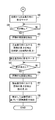
- 3 is a flowchart illustrating a flow of a cropping process of the image reading apparatus according to the first embodiment.
- 3 is a flowchart illustrating a flow of a cropping process of the image reading apparatus according to the first embodiment.
- 3 is a flowchart illustrating a flow of a cropping process of the image reading apparatus according to the first embodiment.
- FIG. 4 is a functional block diagram illustrating a main internal configuration of an image reading apparatus according to a second embodiment.
- FIG. 10 is a flowchart illustrating a flow of image data cutting processing of the image reading apparatus according to the second embodiment.
- A) And (B) is a figure which shows an example of the image data from which the 3rd edge line is detected in the image reading apparatus concerning Embodiment 2.
- FIG. (A) to (D) in the image reading apparatus according to the second embodiment the third edge line has an intersecting edge that intersects with another edge line, and the other edge line is outside the intersecting edge line. It is a figure which shows typically the process which determines whether it has protruded.
- (A) to (H) are diagrams illustrating an example of image data in which a third edge line is detected in the image reading apparatus according to the second embodiment.
- FIG. 6 is a functional block diagram illustrating a main internal configuration of an image reading apparatus according to a third embodiment.
- FIG. 9 is a diagram illustrating a state where an original is placed on an original placement glass in the image reading apparatus according to the third embodiment.
- (A) is a diagram showing a state where the document is in contact with the document guide on the back side, and (B) is an explanatory diagram for explaining a procedure for detecting a document area in that state.
- (A) is a diagram showing a state where a document is in contact with the left document guide, and (B) is an explanatory diagram for explaining a procedure for detecting a document area in that state.
- (A) is a diagram showing a state in which a document is in contact with the left and back document guides
- (B) is an explanatory diagram for explaining a procedure for detecting a document area in that state.
- It is. 10 is a flowchart illustrating an example of a processing operation performed by a control unit of the image reading apparatus according to the third embodiment.
- 10 is a flowchart illustrating an example of a processing operation performed by a control unit of the image reading apparatus according to the third embodiment.
- 10 is a flowchart illustrating an example of a processing operation performed by a control unit of the image reading apparatus according to the third embodiment.
- an image reading apparatus and an image forming apparatus according to an embodiment of the present invention will be described in detail with reference to the drawings.
- an image reading apparatus will be described as an example for the sake of simplicity.
- An image forming apparatus according to the present invention is obtained by combining an image reading apparatus described below with an image forming apparatus such as an electrophotographic system or an inkjet system.
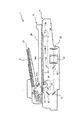
- FIG. 1 is a schematic cross-sectional view showing the overall configuration of the image reading apparatus 1.
- the image reading apparatus 1 in FIG. 1 includes a document transport unit 6 that is a document transport device (ADF: Auto Document Feeder), but may be omitted.
- the image reading apparatus 1 includes an image reading unit 5 and a document conveying unit 6.
- the image reading unit 5 includes a contact glass 161 for placing a document provided on the upper surface, a light source 26 for irradiating the document placed on the contact glass 161, and reflected light from the document to the second mirror 22.
- CCD Charge Coupled Device
- CMOS Complementary Metal Oxide Semiconductor
- the document conveyance unit 6 feeds the document bundle S placed on the document placement unit 61 one by one by the drive of the paper feed roller and the conveyance roller and conveys the document bundle S to a position facing the document reading slit 53. After being enabled to be read by the image reading unit 5 via 53, the document is discharged to the document discharge unit 66.
- FIG. 2 is a plan view schematically showing the contact glass 161 (original placement table).
- the contact glass 161 is for placing a document to be read, and document guides 162F, 162L, 162B, and 162R are arranged along each side of the contact glass 161.
- the manuscript guides 162L and 162B arranged on the left side and the back side have scales for measuring the size of the manuscript, and the operator can refer to the manuscript when placing the manuscript on the contact glass 161.
- the document conveying unit 6 is openable and closable with respect to the contact glass 161 on the upper surface of the image reading unit 5, and the document pressing plate is placed on the surface facing the upper surface of the contact glass 161 when the document conveying unit 6 is in the closed state. 162.
- the light source 26 emits light according to the control of the control unit 100 described later.
- Light passes through the contact glass 161 and is irradiated on the document.
- the reflected light of the document enters the first mirror 21 through the contact glass 161.
- the incident light passes through the second mirror 22, the third mirror 23, and the lens system 24 and then enters the image sensor 25.
- the image sensor 25 operates according to the control of the control unit 100 and converts incident light into an electrical signal.
- the image sensors 25 are arranged in the main scanning direction and obtain an output value for one line in the main scanning direction.
- the light source 26, the first mirror 21, the second mirror 22, and the third mirror 23 are moved at a constant speed in the sub-scanning direction (arrow Y direction) by a drive unit (not shown) such as a motor.
- a drive unit such as a motor.
- the image reading unit 5 can continuously acquire an output value for one line in the main scanning direction of the document in the sub-scanning direction, and as a result, can read the image of the entire document.
- FIG. 3 is a functional block diagram showing the main internal configuration of the image reading apparatus 1.
- the image reading apparatus 1 includes a control unit 100, a document conveying unit 6, an image reading unit 5, an image memory 3, a storage unit 4, an operation unit 7, an image processing unit 8, and a data transmission / reception unit 9.
- the same components as those in FIG. 1 are denoted by the same reference numerals and description thereof is omitted.
- the image memory 3 temporarily stores data read by the image reading unit 5, data received by the data transmission / reception unit 9 from an external device, and the like.
- the storage unit 4 stores programs and data necessary for the operation of the image reading apparatus 1.
- the operation unit 7 receives instructions from the user regarding various operations and processes that can be executed by the image reading apparatus 1.
- the operation unit 7 has a display screen configured with a numeric keypad, hard keys such as a start button and a reset button for executing and stopping various processes, an LCD (Liquid Crystal Display), and the like.
- the display screen displays operation methods, various messages, operation buttons, and the like. Generally, it is configured integrally with a touch panel, and the user can operate the image reading apparatus 1 by touching an operation button displayed on the display screen.
- the operation unit 7 in the present embodiment corresponds to a mode receiving unit in the claims.
- the image processing unit 8 performs image cropping (cropping), image tilt detection / tilt correction, resolution conversion, character conversion processing, image quality adjustment, enlargement / reduction, and the like on the print data stored in the image memory 3.
- a document image cutout unit 81, an inclination detection unit 82, an inclination correction unit 83, a resolution conversion unit 84, and a character conversion unit 85 are provided.
- the document image cutout unit 81 cuts out an image of an area corresponding to the image of the document from the image read by the image reading unit 5. Specifically, the document image cutout unit 81 detects the edge position in the image by performing Hough transform on the image read by the image reading unit 5. Then, the document image cutout unit 81 specifies the edge of the document from the detected edge position, and determines a region surrounded by the edge as a cutout region cut out from the image data.
- the inclination detection unit 82 detects the inclination of the document image included in the image read by the image reading unit 5.
- the tilt correction unit 83 corrects the tilt of the image based on the tilt detected by the tilt detection unit 82 (rotation processing).
- the resolution conversion unit 84 converts the image read by the image reading unit 5 into a predetermined resolution, and corresponds to the first resolution conversion unit and the second resolution conversion unit in the claims. .
- the character conversion unit 85 identifies characters included in the document image and converts them into character data that can be recognized by a computer or the like.
- the character conversion unit 85 performs the character data conversion using, for example, an OCR function.
- the document position detection unit 104 detects the document position from the document image converted to the first resolution.
- the data transmission / reception unit 9 includes an unillustrated encoding / decoding unit, modulation / demodulation unit, and NCU (Network Control Unit), and transmits a facsimile using a public telephone line network. Also, a network interface is provided, and various data are transmitted / received to / from an external device such as a personal computer in the local area or the Internet via a LAN connected to the data transmission / reception unit 9.
- NCU Network Control Unit
- the control unit 100 includes a CPU (Central Processing Unit), a RAM, a ROM, a dedicated hardware circuit, and the like, and governs overall operation control of the image reading apparatus 1.
- the control unit 100 includes a mode setting unit 101, a character size detection unit 102, and a document size detection unit 103.
- the mode setting unit 101 performs image quality priority mode in which resolution conversion is performed after tilt correction is performed on the image read by the image reading unit 5, and resolution conversion is performed after tilt correction of the image read by the image reading unit 5.
- One of the processing speed priority modes to be performed is set.
- the character size detection unit 102 detects the size of characters included in the image read by the image reading unit 5.
- the document size is detected from the document image converted to the first resolution.
- the character size detection unit 102 performs the character size detection by a known method.
- the document size detection unit 103 detects the size of the image read by the image reading unit 5.
- the document size detection unit 103 detects the size of the image by a known method.
- the image reading unit 5 When image processing is performed on an image read by the image reading unit 5 to obtain a read image, first, the image reading unit 5 reads an image with a predetermined resolution, and the resolution of the image is set before image processing. Processing is performed to reduce the image to the second resolution set in advance, perform image processing on the image at the second resolution, and leave the image after the image processing as a read image.
- the reason why the resolution of the image is lowered to the second resolution is to reduce the amount of data as the read image.
- the image reading unit 5 may read a document at a predetermined resolution of 600 dpi, and the resolution conversion unit 84 may reduce the resolution to 200 dpi as the second resolution before image processing. In this case, when the tilt correction unit 83 further performs tilt correction, the image quality after processing varies depending on the processing order of resolution conversion and tilt correction.
- the resolution converting unit 84 reduces the resolution of the image to 200 dpi after the tilt correcting unit 83 corrects the tilt of the 600 dpi image
- the resolution converting unit 84 reduces the resolution of the 600 dpi image.
- the method (1) can suppress image quality deterioration more than the method (2). This is because if the 600 dpi image with a large amount of image information is subjected to tilt correction, data loss after tilt processing can be reduced.
- correcting the tilt of the 200 dpi image requires less memory and less processing time than correcting the tilt of the 600 dpi image because the amount of image information to be processed is smaller. That is, the method (2) can use less memory and the processing time can be shortened than the method (1).
- the mode setting unit 101 sets the processing speed priority mode using the method (1) or the image quality priority mode using the method (2) according to various conditions described below.
- the mode setting unit 101 sets the image quality priority mode.
- the mode setting unit 101 sets the image quality priority mode in order to prevent the image quality from being deteriorated due to the inclination correction after the resolution conversion and the character being crushed and becoming unidentifiable. .
- the mode setting unit 101 sets the processing speed priority mode in order to shorten the processing time.
- the mode setting unit 101 sets either the processing speed priority mode or the image quality priority mode according to the content received by the operation unit 7.
- FIG. 4 to 6 are flowcharts showing the flow of the cropping process, and the conditions when the mode setting unit 101 sets the image quality priority mode or the processing speed priority mode are different.
- FIG. 4 shows a case where the mode setting unit 101 determines the mode depending on whether or not the character recognition process is performed after the cropping process.
- the image reading unit 5 reads a document image at, for example, a predetermined resolution of 600 dpi (step S11), and the resolution conversion unit 84 has a resolution lower than 600 dpi for detecting image information such as an inclination.
- the resolution is converted (for example, 75 dpi) (step S12).
- the reason for converting to a lower resolution is that, when detecting the position, size, inclination, etc. of the image of the document from the image read by the image reading unit 5, it is possible to reduce the processing time if it is detected from the image having a small amount of information. is there.
- the tilt detection unit 82 detects the tilt of the document image from the 75 dpi image (step S13).
- the document size detection unit 103 and the document position detection unit 104 also detect the size of the document image and the document position from the 75 dpi image, and hold the data.
- the mode setting unit 101 sets the image quality priority mode and proceeds with the procedure of the method (1) described above. . That is, using the inclination of the original image detected by the inclination detecting unit 82, the inclination correcting unit 83 corrects the inclination of the 600 dpi image read in step S11 (step S15).
- the original image cutout section 81 cuts out the original image from the image whose inclination is corrected in step S15 (step S16), and the resolution conversion section 84 sets the resolution of the original image to a second resolution lower than 600 dpi (for example, 200 dpi) (step S17).
- the character conversion unit 85 performs a character recognition process (step S21), and the process ends.
- the mode setting unit 101 sets the processing speed priority mode and proceeds with the procedure of the method (2) described above. That is, the document image cutout unit 81 cuts out the document image from the 600 dpi image read in step S11 (step S18).
- the resolution of the image cut out in step S18 is set to be lower than 600 dpi as the predetermined resolution by the resolution conversion unit 84 and higher than 75 dpi as the first resolution, and the second for generating the read image.
- the image is converted into a resolution (for example, 200 dpi), and the inclination correction unit 83 corrects the inclination of the image using the inclination of the original detected by the inclination detection unit 82 (step S20). Then, the process ends.
- FIG. 5 shows a case where the mode setting unit 101 determines the mode according to the size of characters included in the image.
- the processes with the same step numbers as those in FIG. 4 are the same processes, and thus description thereof is omitted.
- step S31 the character size detection unit 102 detects the size of characters included in the image, and the mode setting unit 101 enters the image quality priority mode when the character size is smaller than a predetermined value, and the processing speed priority mode when the character size is greater than the predetermined value.
- FIG. 6 shows a case where the mode setting unit 101 determines the mode according to the size of the image read by the image reading unit 5.
- the processes with the same step numbers as those in FIG. 4 are the same processes, and thus description thereof is omitted.
- step S41 the document size detection unit 103 detects the size of the image read by the image reading unit 5, and the mode setting unit 101 performs processing when the image size is smaller than a predetermined value, and processing when the image size is larger than the predetermined value.
- the mode setting unit 101 performs processing when the image size is smaller than a predetermined value, and processing when the image size is larger than the predetermined value.
- the mode setting unit 101 determines the mode according to each condition.
- the mode may be determined by combining a plurality of conditions.
- the resolution conversion unit 84 changes the resolution of the image.
- image quality degradation can be suppressed. For this reason, it is also possible to suppress a decrease in the character recognition rate when performing the character recognition process.
- the inclination correction unit 83 corrects the inclination of the image after the resolution conversion unit 84 reduces the resolution of the image read by the image reading unit 5 to the second resolution
- the memory usage amount at the time of inclination correction is set. The processing time can be shortened.
- the processing time required for this detection can be shortened.
- FIG. 7 is a functional block diagram of the main internal configuration of the image reading apparatus according to the second embodiment. The same constituent elements as those of the image reading apparatus according to the first embodiment shown in FIG.
- the image reading apparatus includes a width adjustment determination unit 105 as a configuration of the control unit 100.
- the width alignment determination unit 105 has a function of determining whether or not the document is positioned at the end of the reading range on the contact glass 161 when the image reading unit 5 reads an image.
- the edge alignment determination unit 105 determines whether or not the document is located at the end of the reading range on the contact glass 161. Then, the document image cutout unit 81 determines a cutout region to be cut out from the image data according to the result of the edge alignment determination by the edge alignment determination unit 105.
- FIG. 8 is a flowchart showing the flow of the image reading operation in the image reading apparatus 1.
- the image reading unit 5 reads a predetermined reading range on the contact glass 161 under the control of the control unit 100.
- An image is acquired (step S22).
- the edge adjustment determination unit 105 detects an edge point in the image by performing image analysis such as Hough transform on the image acquired in the process of step S22, and the detected edge point is determined in advance. A line that continues several times is detected as the first edge line (step S23).
- the edge alignment determination unit 105 extracts, as the second edge line, an edge line that is perpendicular or horizontal to the four sides constituting the image data from the first edge line (step S24).
- the edge alignment determination unit 105 not only detects edge lines that are strictly perpendicular or horizontal to the four sides constituting the image, but also edge lines that are shifted from the vertical or horizontal lines by an angle within a predetermined value. Extracted as the second edge line.
- the edge alignment determination unit 105 performs a process of rotating the extracted edge line by an angle shifted from the vertical or horizontal line after extracting the edge line, and uses the edge line after the rotation process as the second edge line. Use.
- the edge alignment determination unit 105 selects, as the third edge line, an edge line that is closest to each of the four sides constituting the image from the second edge line (step S25).
- the processing of step S25 is performed by applying the second edge line that is farthest from the center point of the image in the respective directions of the upper side, the lower side, the left side, and the right side of the image. Selected as an edge line.
- third edge lines e1, e2, e3, and e4 are detected in the image D1.
- the third edge line e1 is the second edge line that is farthest from the center point F on the left side
- the third edge line e2 is the position that is farthest from the center point F on the right side. Is the second edge line.
- the third edge line e5 is the second edge line that is farthest from the center point F to the left side and the right side, and the third edge line e6 is from the center point F to the upper side and the lower side. It is the 2nd edge line in the most distant position.
- the edge alignment determination unit 105 includes an intersecting edge line that intersects with another edge line in the third edge line, and the other edge line is more than the intersecting edge line. It is also determined whether or not the toner has protruded outside (step S26). When other edge lines protrude outside the intersecting edge line, it is conceivable that the edge of the document exists further outside the intersecting edge line.
- the third edge line e1 is an intersecting edge line
- the third edge lines e3 and e4 intersecting the third edge line e1 are the other edge lines.
- the third edge lines e3 and e4 protrude outside the first edge line e1, that is, on the left side of the image D1 (see the arrow in the figure). It is determined that the edge line protrudes outside the intersecting edge line.
- the third edge line e2 is an intersecting edge line
- the third edge lines e3 and e4 intersecting the third edge line e2 are the other edge lines.
- the edge alignment determination unit 105 It is determined that no other edge line protrudes outside the intersecting edge line.
- the edge determination unit 105 causes the other edge lines (third edge lines e1 and e2) to be more than the intersecting edge line (third edge line e3). Is determined to protrude outside.
- the edge determination unit 105 causes the other edge lines (third edge lines e1 and e2) to protrude beyond the intersecting edge line (third edge line e4). It is determined that it is not.
- the edge alignment determination unit 105 determines that the document is positioned at the end of the reading range (step S29). Specifically, the edge alignment determination unit 105 determines that the document is edge aligned on one side where other edge lines protrude.
- the edge alignment determination unit 105 determines that the document is within the reading range. It is determined that it is located at the end (step S29). In this case, the edge alignment determination unit 105 determines that the document is aligned on the two sides where the other edge lines protrude.
- the edge alignment determination unit 105 determines that the document is not located at the end of the reading range (step S31). .
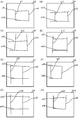
- FIGS. 11A to 11H are diagrams illustrating an example of an image in which the third edge line is detected.
- D3 to D10 indicate image data in each example
- e9 to e38 each indicate a third edge line.
- FIG. 11A corresponds to the above case (i)
- FIG. 11B corresponds to the above case (ii)
- FIG. 11C illustrates the above-mentioned “other edge lines on the outside. This corresponds to the case where there are two protruding intersection edge lines and the two edge lines are orthogonal to each other
- FIG. 11D corresponds to the case (ii) above.
- FIG. 11E corresponds to “a case where there are two intersecting edge lines with other edge lines protruding outside, and the two edge lines are orthogonal to each other”
- FIG. 11 (G) corresponds to the above (iii)
- FIG. 11 (H) corresponds to the above case “when there is only one intersecting edge line protruding from the other edge line”. This corresponds to the case of (ii).
- the document is aligned on the premise that the document does not come into contact with two opposite sides of the contact glass 161.
- the determination unit 105 determines that the document is not aligned.
- the document image cutout unit 81 uses the edge lines other than the intersecting edge lines of the third edge lines and the sides of the image located outside the intersecting edge lines.
- the enclosed area is determined as a cut-out area (step S30).
- an area surrounded by the third edge lines e2 and e4 and the upper side and the left side of the image D1 is determined as a cutout area.
- the document image cutout unit 81 determines an area surrounded by the first edge line located outside the third edge line as a cutout area (step S32).
- the first edge line located on the upper side of the image D4 with respect to the third edge line e13, and the first edge line located on the lower side of the image D4 with respect to the third edge line e14 are detected. Then, the area surrounded by the detected first edge line is determined as the cut-out area.
- step S30 or step S32 the document image cutout unit 81 cuts out the cutout area determined in step S30 or step S32 from the image to generate a main image (step S23).
- the tilt correction unit 83 performs tilt correction processing on the main image generated in step S33 (step S34), and stores the main image after tilt correction in the storage unit 4 (step S35).
- FIG. 12 is a functional block diagram illustrating the main internal configuration of the image reading apparatus according to the third embodiment. The same constituent elements as those of the image reading apparatus according to the first embodiment shown in FIG.
- the image reading apparatus includes a back side detection unit 811 and a left side detection unit 812 as the configuration of the document image cutout unit 81.
- the document image cutout unit 81 detects the contact of the document with the document guides 162L and 162B, and detects the document region.
- the back side detection unit 811 detects contact of the document with the document guide 162B because the shadow of the document guide 162B (document guide shadow) has disappeared based on the reduced image whose resolution has been lowered by the resolution conversion unit 84. To do.
- the left side detection unit 812 detects the contact of the document with the document guide 162L from the shadow generated on the left side of the contact glass 161 based on the reduced image whose resolution has been lowered by the resolution conversion unit 84.
- FIG. 13 is a view showing a state where the document M is placed on the contact glass 161.
- Original shadows SF and SL are generated on the front side and the left side, respectively, and halation portions HB and HR are generated on the back side and the right side, respectively.
- the halation is a phenomenon in which the light intensity increases along the document M and the image becomes white.
- the document shadows SF and SL are black portions, whereas the halation portions HB and HR are white portions.
- a shadow of the document guide 162B (document guide shadow SG) is generated along the back side of the contact glass 161.
- the locations where the document shadows SF and SL, the halation portions HB and HR, and the document guide shadow SG are generated vary depending on the configuration of the image reading apparatus 1 (specifically, the position and orientation of the light source that irradiates the document M). Then, document shadows SF and SL are generated on the near side of document M (lower side in FIG. 13) and the left side in FIG. 13, halation portions HB and HR are generated on the back side (upper side in FIG. 13) of document M and on the right side in FIG. A case where the document guide shadow SG is generated on the back side (upper side in FIG. 13) of the contact glass 161 will be described.
- “back” indicates the upper side in FIG. 13
- “front” indicates the lower side in FIG. 13
- “right” indicates the right side in FIG. 13
- “left” indicates the left side in FIG. 13 (FIGS. 14 to 16). The same in).
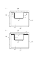
- FIG. 14A is a diagram showing a state in which the document M is in contact with the document guide 162B on the back side
- FIG. 14B illustrates a procedure for detecting an area of the document M in that state. It is explanatory drawing for doing.
- the document guide shadow SG is not generated at the contact portion with the document M.
- Second procedure The search for shadows in the sub-scanning direction (arrow 2 direction in FIG. 14B) is continued, and when a shadow (original guide shadow SG) is detected, the position where the shadow is generated is detected.
- the length of the original M is assumed to be the “left back corner”, and the length where the shadow disappears is estimated as the length of the original M (sub-scanning direction).
- Fourth procedure Search for shadows in the sub-scanning direction to the right (arrow 4 direction in FIG. 14B) and detect that the shadow (document shadow SF) has disappeared.
- M be the “right front corner”, and the length of the shadow is estimated as the length of the document M (sub-scanning direction).
- the detection accuracy can be improved by comparing with the length of the document estimated in the second procedure.
- search for shadows means that main scanning is performed on pixels having a predetermined value (for example, 256-value pixel values indicating black (from 0 to 50)) corresponding to shadows from image data. This is a process for detecting a predetermined number of images in the direction and the sub-scanning direction.
- a predetermined value for example, 256-value pixel values indicating black (from 0 to 50)
- This is a process for detecting a predetermined number of images in the direction and the sub-scanning direction.
- the numerical values of the pixel values shown here are merely examples, and are not limited to the numerical values.
- FIG. 15A is a diagram illustrating a state in which the document M is in contact with the left document guide 162L
- FIG. 15B illustrates a procedure for detecting an area of the document M in that state. It is explanatory drawing for.
- a shadow is generated on the left side of the contact glass 161 due to a shadow (document shadow SF) formed around the document.
- a shadow is searched from the left front corner in the figure in the main scanning direction, and when a shadow (original shadow SF) is detected, it is determined that the original M is in contact with the original guide 162L.
- the position where the shadow is generated is defined as the “left front corner” of the document M.
- Second procedure When searching for the shadow in the sub-scanning direction toward the right and detecting that the shadow (document shadow SF) has disappeared, the position where the shadow disappeared is set as the “right front corner” of the document M, and the length of the shadow The length is estimated as the length of the document M (sub-scanning direction).
- the “search for the halation part HR” means an image (for example, a value indicating white (240 to 255, etc.) indicating a pixel value of 256 values, which is determined in advance from the image data as corresponding to the halation part HR. This is a process for detecting an image in which a predetermined number of pixels are gathered in the main scanning direction and the sub-scanning direction.
- the numerical values of the pixel values shown here are merely examples, and are not limited to the numerical values.
- FIG. 16A is a diagram showing a state in which the document M is in contact with the left and back document guides 162L and 162B
- FIG. 16B is a diagram illustrating detection of an area of the document M in that state. It is explanatory drawing for demonstrating the procedure to perform.
- the document guide shadow SG is not generated at the left back of the contact glass 161.
- Second procedure The search for shadows in the sub-scanning direction is continued, and when the left corner is reached without detecting a shadow (document guide shadow SG), it is determined that the document M is also in contact with the document guide 162L.
- the left back corner of the contact glass 161 is defined as the “left back corner” of the document M, and the length where the shadow disappears is estimated as the length of the document M (sub-scanning direction).
- Fourth procedure When searching for a shadow to the right in the sub-scanning direction and detecting that the shadow (document shadow SF) has disappeared, the position where the shadow disappeared is set as the “right front corner” of the document M, and the length of the shadow The length is estimated as the length of the document M (sub-scanning direction). If the length of the document M estimated in the second procedure is compared, the detection accuracy can be improved.
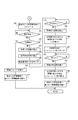
- control unit 100 causes the image reading unit 5 to read a document with the document cover closed (step S40), and stores the image data obtained by the reading by the image reading unit 5 in the image memory 3 (step S41). ).
- the resolution conversion unit 84 creates a reduced image of the document from the image data obtained by reading by the image reading unit 5 stored in the image memory 3 (step S42), and the resolution conversion unit 84 creates the reduced image created. Is stored in the storage unit 4 (step S43).
- the back side detection unit 811 Based on the reduced image data saved in the storage unit 4, the back side detection unit 811 starts from the right back corner in the drawings shown in FIGS. 13 to 16 (the reduced image data is stored).
- a shadow is searched for the position and direction corresponding to the sub-scanning direction from the right back corner (the same applies hereinafter) (step S44), and the back side detection unit 811 detects the shadow ( It is determined whether or not the document guide shadow SG) has disappeared (step S45), and if the back side detection unit 811 determines that the shadow has disappeared (YES in step S45), the back side detection unit 811 has lost the shadow. It is determined whether or not the position is the left back corner (step S46).
- the back side detection unit 811 determines that the position where the shadow disappears is not the left back corner (NO in step S46). If the back side detection unit 811 determines that the document M is in contact with the document guide 162B. The position where the shadow disappears is detected as the “right back corner” of the document M, and the search for the shadow in the sub-scanning direction is continued (steps S47, S48, S49).
- step S46 determines that the position where the shadow has disappeared is the left back corner (YES in step S46)
- the document guide shadow SG has not disappeared, and the document M contacts the document guide 162B.
- step S70 the left side detection unit 812 performs processing for determining whether or not the document M is in contact with the left document guide 162L.
- the back side detection unit 811 determines whether or not a shadow has occurred (step S50), and if the back side detection unit 811 determines that a shadow (original document shadow SG) has occurred (in step S50). YES), the back side detection unit 811 detects the position where the shadow is generated as the “left back corner” of the document M (step S51), and the back side detection unit 811 calculates the length of the shadow disappearing, The length obtained by the calculation is detected as the length of the document M (sub-scanning direction) (step S52), and then the back side detection unit 811 searches for shadows from the back to the front in the main scanning direction. (Step S53).
- step S54 it is determined whether or not it has reached (step S54), and if the back side detection unit 811 determines that it has reached the left back corner without generating a shadow (YES in step S54), the back side detection unit 811 In addition, it is determined that the document M is in contact with not only the back side but also the left side document guide 162L, and the left back corner of the contact glass 161 is detected as the “left back corner” of the document M (step S55, step S55). After that, the process proceeds to step S90 (FIG. 19). If the back side detection unit 811 determines that the left back corner has not been reached (NO in step S54), the process returns to step S50.
- the back side detection unit 811 determines whether or not the shadow has disappeared (step S57), and if the back side detection unit 811 determines that the shadow (document shadow SL) has disappeared (YES in step S57), The back side detection unit 811 detects the position where the shadow disappears as the “left front corner” of the document M (step S58), and the back side detection unit 811 calculates the length of the shadow and obtains it. The length is detected as the length of the document M (main scanning direction) (step S59).
- control unit 100 extracts the image of the document M from the image data stored in the image memory 3 based on the information indicating the area of the document M detected by the back side detection unit 811 (step S60). .
- the left detection unit 812 searches for a shadow in the main scanning direction from the left front corner based on the reduced image data stored in the storage unit 4 (step S70), and the left detection unit 812 If the left detection unit 812 determines that a shadow (original shadow SF or original guide shadow SG) has occurred (YES in step S71), the left detection unit 812 Then, it is determined whether or not the position where the shadow is generated is the left back corner (step S72).
- the left detection unit 812 determines that the position where the shadow is generated is not the left back corner (NO in step S72), since the generated shadow is the document shadow SF, the left detection unit 812 determines that the document M is the document guide 162L. Is detected as the “left front corner” of the document M, and then the shadow is searched for in the right direction in the sub-scanning direction (step S73, S73). Step S74, Step S75).
- the left detection unit 812 determines that the position where the shadow is generated is the left back corner (YES in step S72), the generated shadow is the document guide shadow SG, and the document M is also in the document guide 162L. Since the document M is not in contact with the document guide 162B, it is considered that the document M is not in contact with any of the document guides 162F, 162L, 162B, and 162R, and the control unit 100 performs the reduction stored in the storage unit 4. Based on the image data, the edge of the document M is extracted by a known method to detect the area of the document M (step S76), and the control unit 100 determines the image based on the information indicating the detected area of the document M. An image of the original M is extracted from the image data stored in the memory 3 (step S77). When the inclination of the document M is detected, the control unit 100 performs rotation correction on the document image.
- the left detection unit 812 determines whether or not the shadow has disappeared (step S78), and if the left detection unit 812 determines that the shadow (document shadow SF) has disappeared (YES in step S78), the left detection is performed.
- the unit 812 detects the position where the shadow disappears as the “right front corner” of the document M (step S79), and the left side detection unit 812 calculates the length of the shadow, and the length obtained by the calculation is the document. This is detected as the length of M (sub-scanning direction) (step S80), and then the left detection unit 812 searches the halation part HR toward the back in the main scanning direction (step S81).
- step S82 determines whether or not the halation unit HR has disappeared (step S82), and if the left detection unit 812 determines that the halation unit HR has disappeared (YES in step S82), the left detection unit 812 The position where the halation part HR disappears is detected as the “right back corner” of the document M (step S83), and the left side detection part 812 calculates the length of the halation part HR and calculates the length obtained by the calculation. It is detected as the length of the document M (main scanning direction) (step S84).
- control unit 100 extracts the image of the document M from the image data stored in the image memory 3 based on the information indicating the area of the document M detected by the left side detection unit 812 (step S85).
- step S90 of FIG. 19 the left side detection unit 812 searches for shadows in the main scanning direction from the left front corner based on the reduced image data stored in the storage unit 4 (step S90).
- step S91 determines whether or not a shadow has occurred (step S91), and if the left detection unit 812 determines that a shadow (document shadow SF) has occurred (YES in step S91), the left detection unit 812 detects the position where the shadow is generated as the “left front corner” of the document M (step S92), and the left detection unit 812 detects the “left front corner” and the “left back corner” of the document M (the left back corner of the contact glass 161). ) ”Is detected, and the length obtained by the calculation is detected as the length of the document M (main scanning direction) (step S93), and the left side detection unit 812 moves rightward in the sub-scanning direction.
- the shadow is searched for (step S94).
- the left side detection unit 812 determines whether or not the shadow has disappeared (step S95), and if the left side detection unit 812 determines that the shadow (document shadow SF) has disappeared (YES in step S95), left side detection is performed.
- the unit 812 detects the position where the shadow disappears as the “right front corner” of the document M (step S96), and the left side detection unit 812 calculates the length of the shadow, and the length obtained by the calculation is the document. It is detected as the length of M (sub scanning direction) (step S97).
- control unit 100 detects an area indicated by the information detected by the back side detection unit 811 and the left side detection unit 812 as an area of the document M, and is stored in the image memory 3 according to the detected area of the document M.
- An image corresponding to the area of the document M is extracted from the existing image data (step S98).
- the document guide shadow SG that should have occurred on the side of the contact glass 161 disappears, or the document shadow SF formed around the document M is generated on the side of the contact glass 161, so Since the contact of M with the document guides 162B and 162L is detected, the edge of the document M can be detected even if the edge of the document M cannot be directly extracted from the image data. Therefore, even if the document M is in contact with the document guides 162B and 162L, the area of the document M can be detected appropriately. Therefore, even if the document M is in contact with the document guides 162B and 162L, the area of the document M can be detected appropriately.
- the present invention is not limited to the configuration of the above embodiment, and various modifications can be made.
- the image reading apparatus according to an embodiment of the present invention has been described using a multifunction peripheral. However, this is only an example, and other electronic devices such as a copy function, a printer function, Other image reading apparatuses having a scanner function and a facsimile function may be used.
Abstract
An image-reading unit (5) reads the image of a document at 600 dpi, and a resolution conversion unit (84) converts the resolution of the image to 75 dpi. An inclination detection unit (82) detects the inclination of the image of the document. Then, when a character conversion unit (85) performs character recognition after cropping, a mode-setting unit (101) sets the mode to a picture quality priority mode. An inclination correction unit (83) corrects the inclination of the 600 dpi image using the inclination of the image of the document detected by the inclination detection unit (82). A document image cutout unit (81) cuts out the image of the document, and the resolution conversion unit (84) converts the resolution of the image of the document to 200 dpi. Thereafter, the character conversion unit (85) performs character recognition.
Description
本発明は、原稿を読み取って画像を取得する画像読取装置及び当該画像を印刷する画像形成装置に関するものである。
The present invention relates to an image reading apparatus that acquires an image by reading a document, and an image forming apparatus that prints the image.
原稿の画像を読み取る画像読取装置では、読み取った画像から原稿画像だけを自動的に切り出す機能(オートクロッピング)を備えているものがある。そして多くのオートクロッピング機能は、原稿台に置かれた原稿が斜めに傾いている場合でも、クロッピングを行う際に原稿画像の傾きを検出し、切り出した原稿画像の傾きを補正して表示又は保存まで行う。特許文献1には、画像読取装置が読み取った画像から原稿画像を切り出してその傾きを検出し、検出した傾きに応じて原稿画像の傾きを補正する方法について記載されている。また、特許文献2には、原稿台に複数の原稿が置かれた場合に各原稿画像を切り出してその傾きを検出し、その傾きに従って各原稿画像の傾きを補正する方法について記載されている。
Some image reading apparatuses that read an image of a document have a function (auto cropping) of automatically cutting out only a document image from the read image. Many auto-cropping functions detect the tilt of the document image when cropping, even if the document placed on the document table is tilted, and display or save it by correcting the tilt of the clipped document image. Do until. Japanese Patent Application Laid-Open No. 2004-228561 describes a method of cutting out a document image from an image read by an image reading apparatus, detecting the inclination thereof, and correcting the inclination of the document image in accordance with the detected inclination. Patent Document 2 describes a method of cutting out each original image and detecting its inclination when a plurality of originals are placed on an original table, and correcting the inclination of each original image according to the inclination.
昨今の画像読取装置には、原稿を読み取って原稿画像を取得し、その原稿画像に含まれる文字を特定してコンピューター等が認識可能な文字データに変換する文字変換機能(例えば、光学文字認識、OCR(Optical Character Recognition))を備えたものが多く普及している。OCR等を用いて原稿画像の文字認識を行う場合、原稿画像の画質が悪いと認識精度が悪化する。例えば、読み取った画像の解像度を落として原稿画像の傾き補正を行った後で文字認識処理(OCR)等の画像処理を行う場合、傾き補正で画質が悪化し、文字認識精度が落ちる原因となっていた。このため、傾き検出の処理時間を短縮しつつ、データ量も低減し、傾き補正後の原稿画像の画質の劣化を可能な限り抑えることが望まれる。特許文献1及び2には、読み取った画像の解像度を落として傾き補正する場合については記載されておらず、文字認識処理を行う場合の画質維持について考慮されていない。
In recent image reading apparatuses, a character conversion function (for example, optical character recognition, optical character recognition, etc.) that acquires a document image by reading a document, identifies characters included in the document image, and converts them into character data that can be recognized by a computer or the like. Many devices equipped with OCR (Optical Character Recognition) are widely used. When character recognition of a document image is performed using OCR or the like, the recognition accuracy deteriorates if the image quality of the document image is poor. For example, when image processing such as character recognition processing (OCR) is performed after reducing the resolution of the read image and correcting the inclination of the original image, the image quality deteriorates due to the inclination correction, which causes the character recognition accuracy to deteriorate. It was. For this reason, it is desirable to reduce the amount of data while reducing the processing time of the tilt detection, and to suppress degradation of the image quality of the document image after tilt correction as much as possible. Patent Documents 1 and 2 do not describe the case of correcting the tilt by reducing the resolution of the read image, and do not consider maintaining the image quality when performing the character recognition process.
本発明は、上記の問題を解決するためになされたもので、当該傾き検出の処理時間を短縮しつつ、データ量も低減し、傾き補正後の原稿画像の画質の劣化を可能な限り抑えることを目的とする。
The present invention has been made to solve the above-described problem, and while reducing the processing time of the inclination detection, the data amount is also reduced, and deterioration of the image quality of the original image after the inclination correction is suppressed as much as possible. With the goal.
本発明の一局面にかかる画像読取装置は、原稿を予め定められた解像度で読み取って画像を取得する画像読取部と、前記画像読取部が取得した画像の解像度を、前記予め定められた解像度より低い傾き検出用の第1解像度に変換する第1解像度変換部と、前記第1解像度変換部によって解像度が変換された画像に含まれる前記原稿の画像の傾きを検出する傾き検出部と、前記傾き検出部が検出した傾きに基づいて画像の傾きを補正する傾き補正部と、画像から前記原稿の画像を切り出す原稿画像切出部と、画像の解像度を、前記予め定められた解像度より低く、前記第1解像度よりも高く設定された、読取画像生成用の第2解像度に変換する第2解像度変換部と、画質優先モード又は処理速度優先モードの何れかを設定するモード設定部とを備え、前記モード設定部が前記画質優先モードに設定した場合、前記傾き検出部が検出した傾きに基づいて前記傾き補正部が前記画像読取部により前記予め定められた解像度で取得された画像の傾きを補正した後に、前記原稿画像切出部が当該傾きの補正された画像から前記原稿の画像を切り出して、前記第2解像度変換部が当該切り出された原稿の画像の解像度を前記第2解像度に変換し、前記モード設定部が前記処理速度優先モードに設定した場合、前記原稿画像切出部が前記画像読取部により前記予め定められた解像度で取得された画像から前記原稿の画像を切り出した後に、前記第2解像度変換部が当該切り出された原稿の画像の解像度を前記第2解像度に変換し、前記傾き補正部が当該前記第2解像度への変換後の原稿の画像の傾きを、前記傾き検出部が検出した傾きに基づいて補正する画像読取装置である。
An image reading apparatus according to an aspect of the present invention includes an image reading unit that acquires an image by reading a document at a predetermined resolution, and sets the resolution of the image acquired by the image reading unit from the predetermined resolution. A first resolution conversion unit for converting to a first resolution for low tilt detection, a tilt detection unit for detecting a tilt of an image of the document included in an image whose resolution is converted by the first resolution conversion unit, and the tilt A tilt correction unit that corrects the tilt of the image based on the tilt detected by the detection unit; a document image cutout unit that cuts out the image of the document from an image; and the resolution of the image is lower than the predetermined resolution, A second resolution conversion unit for converting to a second resolution for reading image generation set higher than the first resolution, and a mode setting unit for setting either the image quality priority mode or the processing speed priority mode And when the mode setting unit sets the image quality priority mode, the tilt correction unit is configured to tilt the image acquired by the image reading unit at the predetermined resolution based on the tilt detected by the tilt detection unit. After correcting the image, the document image cutout unit cuts out the image of the document from the image with the tilt corrected, and the second resolution conversion unit changes the resolution of the cut out document image to the second resolution. And when the mode setting unit sets the processing speed priority mode, the document image cutout unit cuts out the document image from the image acquired at the predetermined resolution by the image reading unit. The second resolution conversion unit converts the resolution of the clipped document image into the second resolution, and the tilt correction unit converts the document image after conversion to the second resolution. The can, the tilt detection unit is an image reading apparatus is corrected based on the inclination detected.
また、本発明の別の一局面にかかる画像形成装置は、上記の画像読取装置と、上記の画像読取装置が読み取った画像を用紙に印刷する画像形成部と、を備えた画像形成装置である。
An image forming apparatus according to another aspect of the present invention is an image forming apparatus including the image reading device and an image forming unit that prints an image read by the image reading device on a sheet. .
本発明によれば、傾き検出の処理時間を短縮しつつ、データ量も低減し、傾き補正後の原稿画像の画質の劣化を可能な限り抑えることができる。
According to the present invention, it is possible to reduce the amount of data while reducing the processing time of tilt detection, and to suppress degradation of the image quality of the original image after tilt correction as much as possible.
以下、本発明の実施形態に係る画像読取装置及び画像形成装置について、図面に基づき詳細に説明する。尚、本実施の形態では、説明を簡単にするために、画像読取装置を例に挙げて説明する。そして、本発明における画像形成装置は、以下で説明する画像読取装置に、電子写真方式やインクジェット方式等の画像形成装置を組み合わせたものである。
Hereinafter, an image reading apparatus and an image forming apparatus according to an embodiment of the present invention will be described in detail with reference to the drawings. In the present embodiment, an image reading apparatus will be described as an example for the sake of simplicity. An image forming apparatus according to the present invention is obtained by combining an image reading apparatus described below with an image forming apparatus such as an electrophotographic system or an inkjet system.
<実施形態1>
図1は、画像読取装置1の全体構成を示す概略断面図である。尚、図1の画像読取装置1は、原稿搬送装置(ADF:Auto Document Feeder)である原稿搬送部6を備えているが、なくてもよい。画像読取装置1は、画像読取部5及び原稿搬送部6を備えて構成されている。 <Embodiment 1>
FIG. 1 is a schematic cross-sectional view showing the overall configuration of theimage reading apparatus 1. Note that the image reading apparatus 1 in FIG. 1 includes a document transport unit 6 that is a document transport device (ADF: Auto Document Feeder), but may be omitted. The image reading apparatus 1 includes an image reading unit 5 and a document conveying unit 6.
図1は、画像読取装置1の全体構成を示す概略断面図である。尚、図1の画像読取装置1は、原稿搬送装置(ADF:Auto Document Feeder)である原稿搬送部6を備えているが、なくてもよい。画像読取装置1は、画像読取部5及び原稿搬送部6を備えて構成されている。 <
FIG. 1 is a schematic cross-sectional view showing the overall configuration of the
画像読取部5は、上面に設けられた原稿を載置するためのコンタクトガラス161、コンタクトガラス161に載置された原稿に光を照射する光源26、原稿からの反射光を第2ミラー22に反射する第1ミラー21、反射光をCCD(Charge Coupled Device)やCMOS(Complementary Metal Oxide Semiconductor)等のイメージセンサーで構成された撮像素子25へ導く第3ミラー23及びレンズ系24原稿読取スリット53を有する。
The image reading unit 5 includes a contact glass 161 for placing a document provided on the upper surface, a light source 26 for irradiating the document placed on the contact glass 161, and reflected light from the document to the second mirror 22. A first mirror 21 that reflects, a third mirror 23 that guides the reflected light to an image sensor 25 such as a CCD (Charge Coupled Device) or a CMOS (Complementary Metal Oxide Semiconductor), and a lens system 24 original reading slit 53 Have.
原稿搬送部6は、給紙ローラー及び搬送ローラーの駆動により、原稿載置部61に載置された原稿束Sを1枚ずつ繰り出して原稿読取スリット53に対向する位置へ搬送し、原稿読取スリット53を介して画像読取部5による読取を可能とした後、原稿排出部66へと排出する。
The document conveyance unit 6 feeds the document bundle S placed on the document placement unit 61 one by one by the drive of the paper feed roller and the conveyance roller and conveys the document bundle S to a position facing the document reading slit 53. After being enabled to be read by the image reading unit 5 via 53, the document is discharged to the document discharge unit 66.
図2は、コンタクトガラス161(原稿載置台)を模式的に示した平面図である。コンタクトガラス161は、読取対象となる原稿を載置するものであり、コンタクトガラス161の各辺に沿って、原稿ガイド162F,162L,162B,162Rが配置されている。
FIG. 2 is a plan view schematically showing the contact glass 161 (original placement table). The contact glass 161 is for placing a document to be read, and document guides 162F, 162L, 162B, and 162R are arranged along each side of the contact glass 161.
左側、奥側に配置される原稿ガイド162L、162Bには、原稿のサイズを測るための目盛りが記されており、操作者はコンタクトガラス161に原稿を載せる際の参考にすることができる。
The manuscript guides 162L and 162B arranged on the left side and the back side have scales for measuring the size of the manuscript, and the operator can refer to the manuscript when placing the manuscript on the contact glass 161.
また原稿搬送部6は、画像読取部5の上面にあるコンタクトガラス161に対して開閉自在であり、原稿搬送部6が閉状態にあるときにコンタクトガラス161の上面と対向する面に原稿押さえ板162を有する。
The document conveying unit 6 is openable and closable with respect to the contact glass 161 on the upper surface of the image reading unit 5, and the document pressing plate is placed on the surface facing the upper surface of the contact glass 161 when the document conveying unit 6 is in the closed state. 162.
まず、ユーザーがコンタクトガラス161上に原稿を置いて原稿搬送部6を閉状態にしてスタートボタン(不図示)を押下すると、後述する制御部100の制御に従って光源26が発光し、この光源26の光がコンタクトガラス161を透過して原稿に照射される。その結果、原稿の反射光がコンタクトガラス161を通して第1ミラー21に入射する。この入射光は、第2ミラー22、第3ミラー23及びレンズ系24を通過した後、撮像素子25へ入射する。
First, when a user places a document on the contact glass 161 and closes the document transport unit 6 and presses a start button (not shown), the light source 26 emits light according to the control of the control unit 100 described later. Light passes through the contact glass 161 and is irradiated on the document. As a result, the reflected light of the document enters the first mirror 21 through the contact glass 161. The incident light passes through the second mirror 22, the third mirror 23, and the lens system 24 and then enters the image sensor 25.
撮像素子25は、制御部100の制御に従って動作し、入射光を電気信号へ変換する。撮像素子25は、主走査方向に配列しており、主走査方向の1ライン分の出力値を得る。
The image sensor 25 operates according to the control of the control unit 100 and converts incident light into an electrical signal. The image sensors 25 are arranged in the main scanning direction and obtain an output value for one line in the main scanning direction.
更に、光源26、第1ミラー21、第2ミラー22及び第3ミラー23は、モーター等の駆動部(不図示)によって副走査方向(矢印Y方向)に一定速度で移動する。こうすることで、画像読取部5は原稿の主走査方向1ライン分の出力値を副走査方向に連続して取得し、結果として原稿全体の画像を読み取ることができる。
Furthermore, the light source 26, the first mirror 21, the second mirror 22, and the third mirror 23 are moved at a constant speed in the sub-scanning direction (arrow Y direction) by a drive unit (not shown) such as a motor. In this way, the image reading unit 5 can continuously acquire an output value for one line in the main scanning direction of the document in the sub-scanning direction, and as a result, can read the image of the entire document.
図3は、画像読取装置1の主要内部構成を示す機能ブロック図である。画像読取装置1は、制御部100、原稿搬送部6、画像読取部5、画像メモリー3、記憶部4、操作部7、画像処理部8及びデータ送受信部9を備えて構成される。図1と同じ構成要素には同じ番号を付し、説明を省略する。
FIG. 3 is a functional block diagram showing the main internal configuration of the image reading apparatus 1. The image reading apparatus 1 includes a control unit 100, a document conveying unit 6, an image reading unit 5, an image memory 3, a storage unit 4, an operation unit 7, an image processing unit 8, and a data transmission / reception unit 9. The same components as those in FIG. 1 are denoted by the same reference numerals and description thereof is omitted.
画像メモリー3は、画像読取部5が読み取ったデータやデータ送受信部9が外部装置から受信したデータ等を一時的に保存する。記憶部4は、画像読取装置1の動作に必要なプログラムやデータを記憶する。
The image memory 3 temporarily stores data read by the image reading unit 5, data received by the data transmission / reception unit 9 from an external device, and the like. The storage unit 4 stores programs and data necessary for the operation of the image reading apparatus 1.
操作部7は、画像読取装置1が実行可能な各種動作及び処理についてユーザーからの指示を受け付けるものである。例えば、操作部7は、テンキーや各種処理を実行、停止させるためのスタートボタン、リセットボタン等のハードキー、LCD(Liquid Crystal Display)等で構成された表示画面を有する。表示画面は操作方法や各種メッセージ、操作ボタン等を表示する。一般的にはタッチパネルと一体的に構成されており、表示画面に表示された操作ボタンをユーザーが触れることで画像読取装置1を操作することができる。尚、本実施の形態における操作部7は、請求の範囲におけるモード受付部に相当する。
The operation unit 7 receives instructions from the user regarding various operations and processes that can be executed by the image reading apparatus 1. For example, the operation unit 7 has a display screen configured with a numeric keypad, hard keys such as a start button and a reset button for executing and stopping various processes, an LCD (Liquid Crystal Display), and the like. The display screen displays operation methods, various messages, operation buttons, and the like. Generally, it is configured integrally with a touch panel, and the user can operate the image reading apparatus 1 by touching an operation button displayed on the display screen. The operation unit 7 in the present embodiment corresponds to a mode receiving unit in the claims.
画像処理部8は、画像メモリー3が記憶する印刷データに対して、原稿画像の切り出し(クロッピング)、画像の傾き検出・傾き補正、解像度変換、文字変換処理、画質調整、拡大・縮小等の画像処理を施すものであり、原稿画像切出部81、傾き検出部82、傾き補正部83、解像度変換部84、文字変換部85を有する。
The image processing unit 8 performs image cropping (cropping), image tilt detection / tilt correction, resolution conversion, character conversion processing, image quality adjustment, enlargement / reduction, and the like on the print data stored in the image memory 3. A document image cutout unit 81, an inclination detection unit 82, an inclination correction unit 83, a resolution conversion unit 84, and a character conversion unit 85 are provided.
原稿画像切出部81は、画像読取部5が読み取った画像から原稿の画像に相当する領域の画像を切り取る。具体的には、原稿画像切出部81は、画像読取部5が読み取った画像に対してハフ変換を行うことで画像におけるエッジ位置を検出する。そして原稿画像切出部81は、検出したエッジ位置から原稿の端辺を特定し、当該端辺に囲われた領域を画像データから切り出す切出領域として決定する。傾き検出部82は、画像読取部5が読み取った画像に含まれる原稿の画像の傾きを検出する。
The document image cutout unit 81 cuts out an image of an area corresponding to the image of the document from the image read by the image reading unit 5. Specifically, the document image cutout unit 81 detects the edge position in the image by performing Hough transform on the image read by the image reading unit 5. Then, the document image cutout unit 81 specifies the edge of the document from the detected edge position, and determines a region surrounded by the edge as a cutout region cut out from the image data. The inclination detection unit 82 detects the inclination of the document image included in the image read by the image reading unit 5.
傾き補正部83は、傾き検出部82が検出した傾きに基づいて画像の傾きを補正する(回転処理)。解像度変換部84は、画像読取部5が読み取った画像を予め定められた設定されている解像度に変換するものであり、特許請求の範囲における第1解像度変換部及び第2解像度変換部に相当する。
The tilt correction unit 83 corrects the tilt of the image based on the tilt detected by the tilt detection unit 82 (rotation processing). The resolution conversion unit 84 converts the image read by the image reading unit 5 into a predetermined resolution, and corresponds to the first resolution conversion unit and the second resolution conversion unit in the claims. .
文字変換部85は、原稿の画像に含まれる文字を特定してコンピューター等が認識可能な文字データに変換する。文字変換部85は、例えば、OCR機能により当該文字データ変換を行う。原稿位置検出部104は、第1の解像度に変換された原稿画像から原稿位置を検出する。
The character conversion unit 85 identifies characters included in the document image and converts them into character data that can be recognized by a computer or the like. The character conversion unit 85 performs the character data conversion using, for example, an OCR function. The document position detection unit 104 detects the document position from the document image converted to the first resolution.
データ送受信部9は、図略の符号化/復号化部、変復調部及びNCU(Network Control Unit)を備え、公衆電話回線網を用いてのファクシミリの送信を行うものである。また、ネットワークインターフェースも備え、データ送受信部9に接続されたLAN等を介して、ローカルエリア内又はインターネット上のパーソナルコンピューター等の外部装置と種々のデータの送受信を行う。
The data transmission / reception unit 9 includes an unillustrated encoding / decoding unit, modulation / demodulation unit, and NCU (Network Control Unit), and transmits a facsimile using a public telephone line network. Also, a network interface is provided, and various data are transmitted / received to / from an external device such as a personal computer in the local area or the Internet via a LAN connected to the data transmission / reception unit 9.
制御部100は、CPU(Central Processing Unit)、RAM、ROM及び専用のハードウェア回路等から構成され、画像読取装置1の全体的な動作制御を司る。制御部100は、モード設定部101、文字サイズ検出部102及び原稿サイズ検出部103を備える。
The control unit 100 includes a CPU (Central Processing Unit), a RAM, a ROM, a dedicated hardware circuit, and the like, and governs overall operation control of the image reading apparatus 1. The control unit 100 includes a mode setting unit 101, a character size detection unit 102, and a document size detection unit 103.
モード設定部101は、画像読取部5が読み取った画像に対して傾き補正を行った後に解像度変換を行う画質優先モードと、画像読取部5が読み取った画像の傾き補正を行った後に解像度変換を行う処理速度優先モードの何れかのモードに設定する。
The mode setting unit 101 performs image quality priority mode in which resolution conversion is performed after tilt correction is performed on the image read by the image reading unit 5, and resolution conversion is performed after tilt correction of the image read by the image reading unit 5. One of the processing speed priority modes to be performed is set.
文字サイズ検出部102は、画像読取部5が読み取った画像に含まれる文字のサイズを検出する。ここでは、第1の解像度に変換された原稿画像から原稿サイズを検出する。当該第1の解像度に変換された原稿画像から原稿サイズを検出すること以外については、文字サイズ検出部102は、既知の方法により当該文字サイズ検出を行う。
The character size detection unit 102 detects the size of characters included in the image read by the image reading unit 5. Here, the document size is detected from the document image converted to the first resolution. Except for detecting the document size from the document image converted to the first resolution, the character size detection unit 102 performs the character size detection by a known method.
原稿サイズ検出部103は、画像読取部5が読み取った画像のサイズを検出する。原稿サイズ検出部103は、既知の方法により当該画像のサイズ検出を行う。
The document size detection unit 103 detects the size of the image read by the image reading unit 5. The document size detection unit 103 detects the size of the image by a known method.
画像読取部5が読み取った画像に対して画像処理を施して読取画像を取得する場合、まず、画像読取部5が予め定められた解像度で画像を読み取り、画像処理の前にその画像の解像度を予め設定されている第2の解像度まで落とし、この第2解像度での画像に対して画像処理を行って、当該画像処理後の画像を、読取画像として残す処理が行われる。第2解像度まで画像の解像度を低くするのは、読取画像としてのデータ量を低減するためである。例えば画像読取部5が予め定められた解像度として600dpiの解像度で原稿を読み取り、画像処理の前に解像度変換部84が解像度を第2の解像度としての200dpiに落とす場合がある。この場合、更に傾き補正部83が傾き補正を行うとなると、解像度変換と傾き補正の処理順序によって処理後の画質が異なってくる。
When image processing is performed on an image read by the image reading unit 5 to obtain a read image, first, the image reading unit 5 reads an image with a predetermined resolution, and the resolution of the image is set before image processing. Processing is performed to reduce the image to the second resolution set in advance, perform image processing on the image at the second resolution, and leave the image after the image processing as a read image. The reason why the resolution of the image is lowered to the second resolution is to reduce the amount of data as the read image. For example, the image reading unit 5 may read a document at a predetermined resolution of 600 dpi, and the resolution conversion unit 84 may reduce the resolution to 200 dpi as the second resolution before image processing. In this case, when the tilt correction unit 83 further performs tilt correction, the image quality after processing varies depending on the processing order of resolution conversion and tilt correction.
具体的には、(1)傾き補正部83が600dpiの画像の傾きを補正した後で解像度変換部84がその画像の解像度を200dpiに落とす場合、(2)解像度変換部84が600dpiの画像の解像度を200dpiに落とした後で傾き補正部83がその画像の傾き補正をした場合を比べると、方法(1)の方が方法(2)よりも画質劣化を抑えることができる。それは、画像の情報量が多い600dpiの画像を傾き補正した方が、傾き処理後のデータの欠損が少なくて済むからである。
Specifically, (1) when the resolution converting unit 84 reduces the resolution of the image to 200 dpi after the tilt correcting unit 83 corrects the tilt of the 600 dpi image, (2) the resolution converting unit 84 reduces the resolution of the 600 dpi image. Compared with the case where the inclination correction unit 83 corrects the inclination of the image after the resolution is reduced to 200 dpi, the method (1) can suppress image quality deterioration more than the method (2). This is because if the 600 dpi image with a large amount of image information is subjected to tilt correction, data loss after tilt processing can be reduced.
一方、600dpiの画像の傾きを補正するより200dpiの画像の傾きを補正する方が処理する画像の情報量が少ないために使用するメモリーが少なくて済み、また処理時間も短くなる。つまり、方法(2)の方が方法(1)より使用メモリーを抑え、処理時間を短縮することができる。
On the other hand, correcting the tilt of the 200 dpi image requires less memory and less processing time than correcting the tilt of the 600 dpi image because the amount of image information to be processed is smaller. That is, the method (2) can use less memory and the processing time can be shortened than the method (1).
そこで、モード設定部101が以下で説明する各種条件に応じて方法(1)を用いる処理速度優先モード又は方法(2)を用いる画質優先モードを設定する。
Therefore, the mode setting unit 101 sets the processing speed priority mode using the method (1) or the image quality priority mode using the method (2) according to various conditions described below.
例えば、画像読取部5読み取った画像を解像度変換、傾き補正した後で文字変換部85が画像の文字認識処理を行う場合、画像の画質が悪いと認識精度が悪化し、画像読取装置1の信頼性の低下を招いてしまう。従って、文字変換部85が文字認識処理を行う場合、モード設定部101は画質優先モードに設定する。
For example, when the character conversion unit 85 performs character recognition processing of the image after resolution conversion and inclination correction of the image read by the image reading unit 5, the recognition accuracy deteriorates if the image quality is poor, and the image reading apparatus 1 is reliable. It will cause a decline in sex. Therefore, when the character conversion unit 85 performs character recognition processing, the mode setting unit 101 sets the image quality priority mode.
また、画像に含まれる文字が所定値より小さい場合、解像度変換後の傾き補正によって画質が悪化し、文字が潰れて識別不能になることを防ぐため、モード設定部101は画質優先モードに設定する。
In addition, when the character included in the image is smaller than the predetermined value, the mode setting unit 101 sets the image quality priority mode in order to prevent the image quality from being deteriorated due to the inclination correction after the resolution conversion and the character being crushed and becoming unidentifiable. .
そして、画像読取部5が読み取った画像のサイズが予め定められた値以上である場合、処理時間の短縮化を図るために、モード設定部101は処理速度優先モードに設定する。
When the size of the image read by the image reading unit 5 is equal to or larger than a predetermined value, the mode setting unit 101 sets the processing speed priority mode in order to shorten the processing time.
更に、ユーザーが操作部7を操作することで、処理速度優先モードか画質優先モードの何れかを任意に選択することもできる。モード設定部101は、操作部7が受け付けた内容に従って、処理速度優先モード又は画質優先モードの何れかに設定する。
Furthermore, the user can arbitrarily select either the processing speed priority mode or the image quality priority mode by operating the operation unit 7. The mode setting unit 101 sets either the processing speed priority mode or the image quality priority mode according to the content received by the operation unit 7.
図4~図6は、クロッピング処理の流れを示すフローチャートであり、それぞれモード設定部101が画質優先モード又は処理速度優先モードを設定する際の条件が異なる。図4は、クロッピング処理後に文字認識処理を行うか否かでモード設定部101がモードを決定する場合について示している。
4 to 6 are flowcharts showing the flow of the cropping process, and the conditions when the mode setting unit 101 sets the image quality priority mode or the processing speed priority mode are different. FIG. 4 shows a case where the mode setting unit 101 determines the mode depending on whether or not the character recognition process is performed after the cropping process.
まず画像読取部5は原稿の画像を例えば予め定められた解像度である600dpiで読み取り(ステップS11)、解像度変換部84がこの画像の解像度を600dpiより低い、傾き等の画像情報検出用の第1解像度(例えば75dpi)に変換する(ステップS12)。低い解像度に変換する理由は、画像読取部5が読み取った画像から原稿の画像の位置、サイズ、傾き等を検出する際に、情報量の少ない画像から検出した方が処理時間を短縮できるためである。
First, the image reading unit 5 reads a document image at, for example, a predetermined resolution of 600 dpi (step S11), and the resolution conversion unit 84 has a resolution lower than 600 dpi for detecting image information such as an inclination. The resolution is converted (for example, 75 dpi) (step S12). The reason for converting to a lower resolution is that, when detecting the position, size, inclination, etc. of the image of the document from the image read by the image reading unit 5, it is possible to reduce the processing time if it is detected from the image having a small amount of information. is there.
続いて、傾き検出部82が75dpiの画像から原稿の画像の傾きを検出する(ステップS13)。また、ステップS13では、原稿サイズ検出部103及び原稿位置検出部104も、当該75dpiの画像から、各々原稿画像のサイズ、及び原稿位置を検出し、そのデータを保持しておく。
Subsequently, the tilt detection unit 82 detects the tilt of the document image from the 75 dpi image (step S13). In step S13, the document size detection unit 103 and the document position detection unit 104 also detect the size of the document image and the document position from the 75 dpi image, and hold the data.
そして、クロッピングの後に文字変換部85が文字認識処理(OCR)を行う場合(ステップS14;YES)、モード設定部101は画質優先モードに設定し、上記した方法(1)の手順で処理を進める。つまり、傾き検出部82が検出した原稿の画像の傾きを用いて、傾き補正部83がステップS11で読み取った600dpiの画像の傾きを補正する(ステップS15)。
If the character conversion unit 85 performs character recognition processing (OCR) after cropping (step S14; YES), the mode setting unit 101 sets the image quality priority mode and proceeds with the procedure of the method (1) described above. . That is, using the inclination of the original image detected by the inclination detecting unit 82, the inclination correcting unit 83 corrects the inclination of the 600 dpi image read in step S11 (step S15).
そして、ステップS15で傾きの補正された画像から、原稿画像切出部81が原稿の画像を切り出し(ステップS16)、解像度変換部84がその原稿の画像の解像度を600dpiより低い第2解像度(例えば200dpi)に変換する(ステップS17)。その後、文字変換部85が文字認識処理を行って(ステップS21)、処理を終了する。
Then, the original image cutout section 81 cuts out the original image from the image whose inclination is corrected in step S15 (step S16), and the resolution conversion section 84 sets the resolution of the original image to a second resolution lower than 600 dpi (for example, 200 dpi) (step S17). Thereafter, the character conversion unit 85 performs a character recognition process (step S21), and the process ends.
一方、クロッピングの後に文字変換部85がOCRを行わない場合(ステップS14;NO)、モード設定部101は処理速度優先モードに設定し、上記した方法(2)の手順で処理を進める。つまり、ステップS11で読み取った600dpiの画像から原稿画像切出部81が原稿の画像を切り出す(ステップS18)。
On the other hand, if the character conversion unit 85 does not perform OCR after cropping (step S14; NO), the mode setting unit 101 sets the processing speed priority mode and proceeds with the procedure of the method (2) described above. That is, the document image cutout unit 81 cuts out the document image from the 600 dpi image read in step S11 (step S18).
そして、ステップS18で切り出された画像の解像度を、解像度変換部84が予め定められた解像度としての600dpiより低く、上記第1解像度としての75dpiよりも高く設定された、読取画像生成用の第2解像度(例えば200dpi)に変換し、傾き検出部82が検出した原稿の傾きを用いて傾き補正部83がこの画像の傾きを補正する(ステップS20)。そして処理を終了する。
Then, the resolution of the image cut out in step S18 is set to be lower than 600 dpi as the predetermined resolution by the resolution conversion unit 84 and higher than 75 dpi as the first resolution, and the second for generating the read image. The image is converted into a resolution (for example, 200 dpi), and the inclination correction unit 83 corrects the inclination of the image using the inclination of the original detected by the inclination detection unit 82 (step S20). Then, the process ends.
図5は、画像に含まれる文字のサイズによってモード設定部101がモードを決定する場合について示している。図4と同じステップ番号を付した処理は同じ処理であるため、説明を省略する。
FIG. 5 shows a case where the mode setting unit 101 determines the mode according to the size of characters included in the image. The processes with the same step numbers as those in FIG. 4 are the same processes, and thus description thereof is omitted.
ステップS31において、文字サイズ検出部102は画像に含まれる文字のサイズを検出し、モード設定部101は文字サイズが所定値より小さい場合は画質優先モード、所定値以上の場合は処理速度優先モードに設定する。
In step S31, the character size detection unit 102 detects the size of characters included in the image, and the mode setting unit 101 enters the image quality priority mode when the character size is smaller than a predetermined value, and the processing speed priority mode when the character size is greater than the predetermined value. Set.
図6は、画像読取部5が読み取った画像のサイズによってモード設定部101がモードを決定する場合について示している。図4と同じステップ番号を付した処理は同じ処理であるため、説明を省略する。
FIG. 6 shows a case where the mode setting unit 101 determines the mode according to the size of the image read by the image reading unit 5. The processes with the same step numbers as those in FIG. 4 are the same processes, and thus description thereof is omitted.
ステップS41において、原稿サイズ検出部103は画像読取部5が読み取った画像のサイズを検出し、モード設定部101は画像のサイズが所定値より小さい場合は画質優先モード、所定値以上の場合は処理速度優先モードに設定する。
In step S41, the document size detection unit 103 detects the size of the image read by the image reading unit 5, and the mode setting unit 101 performs processing when the image size is smaller than a predetermined value, and processing when the image size is larger than the predetermined value. Set to speed priority mode.
尚、上記の実施の形態では、モード設定部101のモードの決定の仕方として条件別にそれぞれ説明したが、複数の条件を組み合わせてモードを決定するようにしてもよい。
In the above embodiment, the mode setting unit 101 determines the mode according to each condition. However, the mode may be determined by combining a plurality of conditions.
以上、説明したように、実施形態1にかかる画像読取装置によれば、傾き補正部83が画像読取部5の読み取った画像の傾きを補正した後で、解像度変換部84がこの画像の解像度を第2解像度まで落とすことで、画質劣化を抑えることができる。このため、文字認識処理を行う際の文字認識率の低下を抑えることも可能になる。一方、解像度変換部84が画像読取部5の読み取った画像の解像度を上記第2解像度まで落とした後で傾き補正部83がこの画像の傾きを補正する場合は、傾き補正時のメモリー使用量を抑え、処理時間を短縮することができる。
As described above, according to the image reading apparatus of the first embodiment, after the inclination correction unit 83 corrects the inclination of the image read by the image reading unit 5, the resolution conversion unit 84 changes the resolution of the image. By degrading to the second resolution, image quality degradation can be suppressed. For this reason, it is also possible to suppress a decrease in the character recognition rate when performing the character recognition process. On the other hand, when the inclination correction unit 83 corrects the inclination of the image after the resolution conversion unit 84 reduces the resolution of the image read by the image reading unit 5 to the second resolution, the memory usage amount at the time of inclination correction is set. The processing time can be shortened.
また、画像読取部5が読み取った予め定められた解像度の画像を、解像度変換部84が傾き検出用の第1解像度に変換した後、当該画像を用いて、原稿の画像の位置、サイズ、傾き等を検出するため、この検出に要する処理時間を短縮することができる。
In addition, after the image having the predetermined resolution read by the image reading unit 5 is converted into the first resolution for tilt detection by the resolution conversion unit 84, the position, size, and tilt of the image of the document are used using the image. Therefore, the processing time required for this detection can be shortened.
<実施形態2>
図7は、実施形態2にかかる画像読取装置の主要内部構成を示す機能ブロック図である。図3に示した実施形態1にかかる画像読取装置の構成要素と同じ構成要素には同じ番号を付し、説明を省略する。 <Embodiment 2>
FIG. 7 is a functional block diagram of the main internal configuration of the image reading apparatus according to the second embodiment. The same constituent elements as those of the image reading apparatus according to the first embodiment shown in FIG.
図7は、実施形態2にかかる画像読取装置の主要内部構成を示す機能ブロック図である。図3に示した実施形態1にかかる画像読取装置の構成要素と同じ構成要素には同じ番号を付し、説明を省略する。 <
FIG. 7 is a functional block diagram of the main internal configuration of the image reading apparatus according to the second embodiment. The same constituent elements as those of the image reading apparatus according to the first embodiment shown in FIG.
図7に示すように、実施形態2にかかる画像読取装置は、制御部100の構成として幅寄せ判定部105を備えている。幅寄せ判定部105は、画像読取部5による画像の読み取りの際に原稿がコンタクトガラス161上の読み取り範囲の端に位置しているか否かを判定する機能を有する。
As shown in FIG. 7, the image reading apparatus according to the second embodiment includes a width adjustment determination unit 105 as a configuration of the control unit 100. The width alignment determination unit 105 has a function of determining whether or not the document is positioned at the end of the reading range on the contact glass 161 when the image reading unit 5 reads an image.
ここで、読み取り対象の原稿がコンタクトガラス161上の予め定められた読み取り範囲の端に位置している場合、ハフ変換による画像データにおけるエッジ位置の検出がうまくいかない場合がある。例えば、原稿がコンタクトガラス161の上辺、下辺、左辺、または右辺の少なくとも何れか1辺に接した状態でコンタクトガラス161上に載置された場合、ハフ変換によるエッジ位置の検出でコンタクトガラス161の一辺に接した原稿の端辺が検出できないときがある。この問題を解消するために、実施形態2にかかる画像読取装置では、端寄せ判定部105がコンタクトガラス161上の読み取り範囲の端に原稿が位置しているか否かを判定している。そして、原稿画像切出部81は、端寄せ判定部105による端寄せ判定結果に応じて、画像データから切り出す切出領域を決定する。
Here, when the document to be read is located at the end of the predetermined reading range on the contact glass 161, the detection of the edge position in the image data by the Hough transform may not be successful. For example, when the document is placed on the contact glass 161 in contact with at least one of the upper side, the lower side, the left side, or the right side of the contact glass 161, the edge position of the contact glass 161 is detected by the Hough transform. There are times when the edge of a document that touches one side cannot be detected. In order to solve this problem, in the image reading apparatus according to the second embodiment, the edge alignment determination unit 105 determines whether or not the document is located at the end of the reading range on the contact glass 161. Then, the document image cutout unit 81 determines a cutout region to be cut out from the image data according to the result of the edge alignment determination by the edge alignment determination unit 105.
以下、この端寄せ判定部105による端寄せ判定処理および原稿画像切出部81による画像データの切出処理の詳細、すなわち、実施形態1のステップS16およびステップS18に示した処理の詳細を図8を主に参照しながら、必要に応じて図9(A)乃至図11(H)を適宜参照して説明する。
Hereinafter, details of the edge alignment determination processing by the edge alignment determination unit 105 and image data extraction processing by the document image extraction unit 81, that is, details of the processing shown in steps S16 and S18 of the first embodiment will be described with reference to FIG. 9 (A) to FIG. 11 (H) will be described as needed with reference to FIGS.
図8は、画像読取装置1における画像読み取り動作の流れを示すフローチャートである。画像の読み取りを行うべき旨の画像読取指示を受け付けると(ステップS21においてYES)、制御部100による制御のもと、画像読取部5は、コンタクトガラス161上の予め定められた読み取り範囲を読み取って、画像を取得する(ステップS22)。
FIG. 8 is a flowchart showing the flow of the image reading operation in the image reading apparatus 1. When an image reading instruction indicating that the image should be read is received (YES in step S21), the image reading unit 5 reads a predetermined reading range on the contact glass 161 under the control of the control unit 100. An image is acquired (step S22).
その後、端寄せ判定部105は、ステップS22の処理で取得した画像に対してハフ変換などの画像解析を行うことにより、当該画像におけるエッジ点を検出し、当該検出したエッジ点が予め定められた数以上連続するものを第1のエッジ線として検出する(ステップS23)。
Thereafter, the edge adjustment determination unit 105 detects an edge point in the image by performing image analysis such as Hough transform on the image acquired in the process of step S22, and the detected edge point is determined in advance. A line that continues several times is detected as the first edge line (step S23).
ステップS23の処理後、端寄せ判定部105は、第1のエッジ線のうち画像データを構成する4辺に垂直または水平となるエッジ線を第2のエッジ線として抽出する(ステップS24)。
After the processing in step S23, the edge alignment determination unit 105 extracts, as the second edge line, an edge line that is perpendicular or horizontal to the four sides constituting the image data from the first edge line (step S24).
なお、端寄せ判定部105は、画像を構成する4辺と厳密に垂直または水平となるエッジ線のみならず、垂直または水平となる線から予め定められた値以内の角度だけずれたエッジ線も第2のエッジ線として抽出する。端寄せ判定部105は、当該エッジ線を抽出後、垂直または水平となる線からずれた角度だけ抽出したエッジ線を回転させる処理を行い、当該回転処理後のエッジ線を第2のエッジ線として用いる。
The edge alignment determination unit 105 not only detects edge lines that are strictly perpendicular or horizontal to the four sides constituting the image, but also edge lines that are shifted from the vertical or horizontal lines by an angle within a predetermined value. Extracted as the second edge line. The edge alignment determination unit 105 performs a process of rotating the extracted edge line by an angle shifted from the vertical or horizontal line after extracting the edge line, and uses the edge line after the rotation process as the second edge line. Use.
ステップS24の処理後、端寄せ判定部105は、第2のエッジ線のうち画像を構成する4辺のそれぞれに最も近い位置にあるエッジ線を第3のエッジ線として選択する(ステップS25)。このステップS25の処理は、換言すれば、画像の中心点から、画像の上辺側、下辺側、左辺側、右辺側のそれぞれの方向に最も離れた位置にある第2のエッジ線を第3のエッジ線として選択している。
After the processing in step S24, the edge alignment determination unit 105 selects, as the third edge line, an edge line that is closest to each of the four sides constituting the image from the second edge line (step S25). In other words, the processing of step S25 is performed by applying the second edge line that is farthest from the center point of the image in the respective directions of the upper side, the lower side, the left side, and the right side of the image. Selected as an edge line.
図9(A)に示す例では、画像D1内に4つの第3のエッジ線e1、e2、e3、およびe4が検出されている。例えば、第3のエッジ線e1は、中心点Fから左辺側に最も離れた位置にある第2のエッジ線であり、第3のエッジ線e2は、中心点Fから右辺側に最も離れた位置にある第2のエッジ線である。
In the example shown in FIG. 9A, four third edge lines e1, e2, e3, and e4 are detected in the image D1. For example, the third edge line e1 is the second edge line that is farthest from the center point F on the left side, and the third edge line e2 is the position that is farthest from the center point F on the right side. Is the second edge line.
また、図9(B)に示す例では、画像D2内に2つの第3のエッジ線e5およびe6が検出されている。第3のエッジ線e5は、中心点Fから左辺側および右辺側に最も離れた位置にある第2のエッジ線であり、第3のエッジ線e6は、中心点Fから上辺側および下辺側に最も離れた位置にある第2のエッジ線である。
In the example shown in FIG. 9B, two third edge lines e5 and e6 are detected in the image D2. The third edge line e5 is the second edge line that is farthest from the center point F to the left side and the right side, and the third edge line e6 is from the center point F to the upper side and the lower side. It is the 2nd edge line in the most distant position.
図8に戻って、ステップS25の処理後、端寄せ判定部105は、第3のエッジ線内に他のエッジ線と交差する交差エッジ線が存在し、当該他のエッジ線が交差エッジ線よりも外側にはみ出しているか否かを判定する(ステップS26)。他のエッジ線が交差エッジ線よりも外側にはみ出している場合、その交差エッジ線よりもさらに外側に原稿の端辺が存在することが考えられる。
Returning to FIG. 8, after the process of step S <b> 25, the edge alignment determination unit 105 includes an intersecting edge line that intersects with another edge line in the third edge line, and the other edge line is more than the intersecting edge line. It is also determined whether or not the toner has protruded outside (step S26). When other edge lines protrude outside the intersecting edge line, it is conceivable that the edge of the document exists further outside the intersecting edge line.
図10(A)に示す例では、第3のエッジ線e1が交差エッジ線となり、第3のエッジ線e1と交差する第3のエッジ線e3およびe4が上記の他のエッジ線となる。この場合、第3のエッジ線e3およびe4が、第1のエッジ線e1よりも外側、すなわち画像D1の左辺側にはみ出している(図中の矢印参照)ため、端寄せ判定部105は、他のエッジ線が交差エッジ線よりも外側にはみ出していると判定する。
In the example shown in FIG. 10A, the third edge line e1 is an intersecting edge line, and the third edge lines e3 and e4 intersecting the third edge line e1 are the other edge lines. In this case, the third edge lines e3 and e4 protrude outside the first edge line e1, that is, on the left side of the image D1 (see the arrow in the figure). It is determined that the edge line protrudes outside the intersecting edge line.
図10(B)に示す例では、第3のエッジ線e2が交差エッジ線となり、第3のエッジ線e2と交差する第3のエッジ線e3およびe4が上記の他のエッジ線となる。この場合、第3のエッジ線e3およびe4が、第3のエッジ線e2よりも外側、すなわち、画像D1の右辺側にはみ出していない(図中の矢印参照)ため、端寄せ判定部105は、他のエッジ線が交差エッジ線よりも外側にはみ出していないと判定する。
In the example shown in FIG. 10B, the third edge line e2 is an intersecting edge line, and the third edge lines e3 and e4 intersecting the third edge line e2 are the other edge lines. In this case, since the third edge lines e3 and e4 do not protrude beyond the third edge line e2, that is, on the right side of the image D1 (see the arrow in the drawing), the edge alignment determination unit 105 It is determined that no other edge line protrudes outside the intersecting edge line.
上記と同様にして、図10(C)に示す例では、端寄せ判定部105により、他のエッジ線(第3のエッジ線e1およびe2)が交差エッジ線(第3のエッジ線e3)よりも外側にはみ出していると判定される。また、図10(D)に示す例では、端寄せ判定部105により、他のエッジ線(第3のエッジ線e1およびe2)が交差エッジ線(第3のエッジ線e4)よりも外側にはみ出していないと判定される。
Similarly to the above, in the example shown in FIG. 10C, the edge determination unit 105 causes the other edge lines (third edge lines e1 and e2) to be more than the intersecting edge line (third edge line e3). Is determined to protrude outside. In the example shown in FIG. 10D, the edge determination unit 105 causes the other edge lines (third edge lines e1 and e2) to protrude beyond the intersecting edge line (third edge line e4). It is determined that it is not.
図8に戻って、ステップS26の処理での判定結果において、外側に他のエッジ線のはみ出している交差エッジ線が1つだけ存在する場合(ステップS27においてYES)、端寄せ判定部105は、原稿が読み取り範囲の端に位置していると判定する(ステップS29)。具体的には、端寄せ判定部105は、他のエッジ線がはみ出している1つの辺側に原稿が端寄せされていることを判定する。
Returning to FIG. 8, in the determination result in the process of step S <b> 26, when there is only one intersecting edge line protruding from the other edge line on the outside (YES in step S <b> 27), the edge alignment determination unit 105 It is determined that the document is positioned at the end of the reading range (step S29). Specifically, the edge alignment determination unit 105 determines that the document is edge aligned on one side where other edge lines protrude.
また、外側に他のエッジ線がはみ出している交差エッジ線が2つ存在し、その2つのエッジ線が互いに直交する場合(ステップS28においてYES)、端寄せ判定部105は、原稿が読み取り範囲の端に位置していると判定する(ステップS29)。この場合、端寄せ判定部105は、他のエッジ線がはみ出している2つの辺側に原稿が端寄せされていることを判定する。
Further, when there are two intersecting edge lines that protrude from the other edge lines and the two edge lines are orthogonal to each other (YES in step S28), the edge alignment determination unit 105 determines that the document is within the reading range. It is determined that it is located at the end (step S29). In this case, the edge alignment determination unit 105 determines that the document is aligned on the two sides where the other edge lines protrude.
一方、上記の2つ以外の場合、すなわち下記の(i)~(iii)の3つの場合、端寄せ判定部105は、原稿が読み取り範囲の端に位置していないと判定する(ステップS31)。
On the other hand, in cases other than the above two cases, that is, in the following three cases (i) to (iii), the edge alignment determination unit 105 determines that the document is not located at the end of the reading range (step S31). .
(i)外側に他のエッジ線がはみ出している交差エッジ線が1つも存在しない場合
(ii)外側に他のエッジ線がはみ出している交差エッジ線が2つ存在するが、その2つのエッジ線が互いに直交しない場合
(iii)外側に他のエッジ線がはみ出している交差エッジ線が3つ以上存在する場合 (I) When there is no crossing edge line protruding from the other edge line outside (ii) There are two crossing edge lines protruding from the other edge line, but the two edge lines (Iii) When there are three or more intersecting edge lines protruding from the other edge lines on the outside
図11(A)~図11(H)は、第3のエッジ線が検出される画像の一例を示す図である。これらの図において、D3~D10は、それぞれの例における画像データを示し、e9~e38はそれぞれ第3のエッジ線を示す。
FIGS. 11A to 11H are diagrams illustrating an example of an image in which the third edge line is detected. In these drawings, D3 to D10 indicate image data in each example, and e9 to e38 each indicate a third edge line.
図11(A)は上記の(i)の場合に該当し、図11(B)は上記の(ii)の場合に該当し、図11(C)は上記の「外側に他のエッジ線がはみ出している交差エッジ線が2つ存在し、その2つのエッジ線が互いに直交する場合」に該当し、図11(D)は上記の(ii)の場合に該当する。また、図11(E)は、「外側に他のエッジ線がはみ出している交差エッジ線が2つ存在し、その2つのエッジ線が互いに直交する場合」に該当し、図11(F)は、「外側に他のエッジ線のはみ出している交差エッジ線が1つだけ存在する場合」に該当し、図11(G)は、上記の(iii)に該当し、図11(H)は上記の(ii)の場合に該当する。
11A corresponds to the above case (i), FIG. 11B corresponds to the above case (ii), and FIG. 11C illustrates the above-mentioned “other edge lines on the outside. This corresponds to the case where there are two protruding intersection edge lines and the two edge lines are orthogonal to each other, and FIG. 11D corresponds to the case (ii) above. Further, FIG. 11E corresponds to “a case where there are two intersecting edge lines with other edge lines protruding outside, and the two edge lines are orthogonal to each other”, and FIG. 11 (G) corresponds to the above (iii), and FIG. 11 (H) corresponds to the above case “when there is only one intersecting edge line protruding from the other edge line”. This corresponds to the case of (ii).
なお上記の(ii)の場合、すなわち図11(B)や図11(D)の場合、原稿がコンタクトガラス161の対向する2辺にともに接触することがないという前提のもとに、端寄せ判定部105は、原稿が端寄せされていないと判定している。
In the case of the above (ii), that is, in the case of FIG. 11B or FIG. 11D, the document is aligned on the premise that the document does not come into contact with two opposite sides of the contact glass 161. The determination unit 105 determines that the document is not aligned.
図8に戻って、ステップS29の処理後、原稿画像切出部81は、第3のエッジ線のうちの交差エッジ線以外のエッジ線、および交差エッジ線よりも外側に位置する画像の辺により囲われた領域を切出領域として決定する(ステップS30)。図9(A)に示す例では、第3のエッジ線e2およびe4と、画像D1の上辺および左辺とにより囲われた領域が切出領域として決定される。
Returning to FIG. 8, after the process of step S <b> 29, the document image cutout unit 81 uses the edge lines other than the intersecting edge lines of the third edge lines and the sides of the image located outside the intersecting edge lines. The enclosed area is determined as a cut-out area (step S30). In the example shown in FIG. 9A, an area surrounded by the third edge lines e2 and e4 and the upper side and the left side of the image D1 is determined as a cutout area.
また、ステップS31の処理後、原稿画像切出部81は、第3のエッジ線よりも外側に位置する第1のエッジ線により囲われた領域を切出領域として決定する(ステップS32)。図11(B)に示す例では、第3のエッジ線e11よりも画像D4の左辺側に位置する第1のエッジ線、第3のエッジ線e12よりも画像D4の右辺側に位置する第1のエッジ線、第3のエッジ線e13よりも画像D4の上辺側に位置する第1のエッジ線、および第3のエッジ線e14よりも画像D4の下辺側に位置する第1のエッジ線が検出され、当該検出された第1のエッジ線に囲われた領域が切出領域として決定される。
Further, after the process of step S31, the document image cutout unit 81 determines an area surrounded by the first edge line located outside the third edge line as a cutout area (step S32). In the example shown in FIG. 11B, the first edge line located on the left side of the image D4 with respect to the third edge line e11 and the first edge line located on the right side of the image D4 with respect to the third edge line e12. , The first edge line located on the upper side of the image D4 with respect to the third edge line e13, and the first edge line located on the lower side of the image D4 with respect to the third edge line e14 are detected. Then, the area surrounded by the detected first edge line is determined as the cut-out area.
ステップS30またはステップS32の処理後、原稿画像切出部81は、ステップS30またはステップS32の処理で決定した切出領域を画像から切り出して、本画像を生成する(ステップS23)。
After step S30 or step S32, the document image cutout unit 81 cuts out the cutout area determined in step S30 or step S32 from the image to generate a main image (step S23).
その後傾き補正部83は、ステップS33の処理で生成した本画像に対して傾き補正処理を行い(ステップS34)、傾き補正後の本画像を記憶部4に記憶させる(ステップS35)。
Thereafter, the tilt correction unit 83 performs tilt correction processing on the main image generated in step S33 (step S34), and stores the main image after tilt correction in the storage unit 4 (step S35).
以上のように、上記の画像読取装置によれば、読み取り対象の原稿がコンタクトガラス161上の予め定められた読み取り範囲の端に位置する場合であっても、原稿の端辺を正確に検出することができる。
As described above, according to the above-described image reading apparatus, even when the original to be read is located at the end of the predetermined reading range on the contact glass 161, the edge of the original is accurately detected. be able to.
<実施形態3>
図12は、実施形態3にかかる画像読取装置の主要内部構成を示す機能ブロック図である。図3に示した実施形態1にかかる画像読取装置の構成要素と同じ構成要素には同じ番号を付し、説明を省略する。 <Embodiment 3>
FIG. 12 is a functional block diagram illustrating the main internal configuration of the image reading apparatus according to the third embodiment. The same constituent elements as those of the image reading apparatus according to the first embodiment shown in FIG.
図12は、実施形態3にかかる画像読取装置の主要内部構成を示す機能ブロック図である。図3に示した実施形態1にかかる画像読取装置の構成要素と同じ構成要素には同じ番号を付し、説明を省略する。 <
FIG. 12 is a functional block diagram illustrating the main internal configuration of the image reading apparatus according to the third embodiment. The same constituent elements as those of the image reading apparatus according to the first embodiment shown in FIG.
図12に示すように、実施形態3にかかる画像読取装置は、原稿画像切出部81の構成として、奥側検出部811と左側検出部812とを備える。
As shown in FIG. 12, the image reading apparatus according to the third embodiment includes a back side detection unit 811 and a left side detection unit 812 as the configuration of the document image cutout unit 81.
原稿画像切出部81は、原稿の原稿ガイド162L,162Bへの接触を検出し、原稿の領域を検出する。
The document image cutout unit 81 detects the contact of the document with the document guides 162L and 162B, and detects the document region.
奥側検出部811は、解像度変換部84により解像度が下げられた縮小画像に基づいて、原稿ガイド162Bの影(原稿ガイド影)が消えていることから、原稿ガイド162Bへの原稿の接触を検出する。
The back side detection unit 811 detects contact of the document with the document guide 162B because the shadow of the document guide 162B (document guide shadow) has disappeared based on the reduced image whose resolution has been lowered by the resolution conversion unit 84. To do.
左側検出部812は、解像度変換部84により解像度が下げられた縮小画像に基づいて、コンタクトガラス161の左側の辺に発生する影から、原稿ガイド162Lへの原稿の接触を検出する。
The left side detection unit 812 detects the contact of the document with the document guide 162L from the shadow generated on the left side of the contact glass 161 based on the reduced image whose resolution has been lowered by the resolution conversion unit 84.
ここで、上記の原稿ガイド影やコンタクトガラス161の左側の辺に発生する影について説明する。
Here, the document guide shadow and the shadow generated on the left side of the contact glass 161 will be described.
図13は、コンタクトガラス161に原稿Mが載置されている状態を示した図である。原稿Mの周囲には手前側、左側それぞれに原稿影SF,SLが生じ、奥側、右側それぞれにハレーション部HB,HRが生じている。ハレーションとは、原稿Mに沿って光強度が強くなり、画像が真っ白くなる現象であり、原稿影SF,SLが黒い部分であるのに対し、ハレーション部HB,HRは白い部分となる。
FIG. 13 is a view showing a state where the document M is placed on the contact glass 161. Around the original M, original shadows SF and SL are generated on the front side and the left side, respectively, and halation portions HB and HR are generated on the back side and the right side, respectively. The halation is a phenomenon in which the light intensity increases along the document M and the image becomes white. The document shadows SF and SL are black portions, whereas the halation portions HB and HR are white portions.
また、コンタクトガラス161の奥側の辺に沿って、原稿ガイド162Bの影(原稿ガイド影SG)が生じている。
Further, a shadow of the document guide 162B (document guide shadow SG) is generated along the back side of the contact glass 161.
原稿影SF,SL、ハレーション部HB,HR、及び原稿ガイド影SGの生じる場所は、画像読取装置1の構成(具体的には、原稿Mを照射する光源の位置や向き)によって変わるが、ここでは原稿Mの手前側(図13における下側)と図13における左側に原稿影SF,SL、原稿Mの奥側(図13における上側)と図13における右側にハレーション部HB,HRが生じ、コンタクトガラス161の奥側(図13における上側)の辺に原稿ガイド影SGが生じる場合について説明する。なお、以下には、「奥」は図13における上側、「手前」は図13における下側、「右」は図13における右側、「左」は図13における左側を示す(図14~図16において同様)。
The locations where the document shadows SF and SL, the halation portions HB and HR, and the document guide shadow SG are generated vary depending on the configuration of the image reading apparatus 1 (specifically, the position and orientation of the light source that irradiates the document M). Then, document shadows SF and SL are generated on the near side of document M (lower side in FIG. 13) and the left side in FIG. 13, halation portions HB and HR are generated on the back side (upper side in FIG. 13) of document M and on the right side in FIG. A case where the document guide shadow SG is generated on the back side (upper side in FIG. 13) of the contact glass 161 will be described. In the following, “back” indicates the upper side in FIG. 13, “front” indicates the lower side in FIG. 13, “right” indicates the right side in FIG. 13, and “left” indicates the left side in FIG. 13 (FIGS. 14 to 16). The same in).
図14(A)は、奥側の原稿ガイド162Bに原稿Mが接触している状態を示した図であり、図14(B)は、その状態での原稿Mの領域を検出する手順を説明するための説明図である。原稿ガイド162Bに原稿Mが接触している場合、原稿Mとの接触部分には原稿ガイド影SGは発生しない。
FIG. 14A is a diagram showing a state in which the document M is in contact with the document guide 162B on the back side, and FIG. 14B illustrates a procedure for detecting an area of the document M in that state. It is explanatory drawing for doing. When the document M is in contact with the document guide 162B, the document guide shadow SG is not generated at the contact portion with the document M.
すなわち、原稿ガイド影SGが発生するはずのコンタクトガラス161の奥側の辺に影が発生していない場合、原稿ガイド162Bに原稿Mが接触していると推定できる。
That is, when no shadow is generated on the back side of the contact glass 161 where the document guide shadow SG should be generated, it can be estimated that the document M is in contact with the document guide 162B.
原稿Mの領域を検出する手順の一例について、図14(B)を参照して説明する。
An example of a procedure for detecting the area of the document M will be described with reference to FIG.
第1手順:図中の右奥隅から副走査方向(図14(B)における矢印1方向)に影をサーチし、影(原稿ガイド影SG)が消えているのを検出すると、原稿Mが原稿ガイド162Bに接触していると判定し、影が消えた位置を原稿Mの「右奥隅」とする。
First procedure: When a shadow is searched from the right back corner in the figure in the sub-scanning direction (arrow 1 direction in FIG. 14B) and the shadow (original guide shadow SG) is detected to be disappeared, the original M is It is determined that the document guide 162B is in contact, and the position where the shadow disappears is defined as the “right back corner” of the document M.
第2手順:副走査方向(図14(B)における矢印2方向)への影のサーチを継続し、影(原稿ガイド影SG)が発生しているのを検出すると、影が発生した位置を原稿Mの「左奥隅」とし、影が消えている長さを原稿Mの長さ(副走査方向)と推定する。
Second procedure: The search for shadows in the sub-scanning direction (arrow 2 direction in FIG. 14B) is continued, and when a shadow (original guide shadow SG) is detected, the position where the shadow is generated is detected. The length of the original M is assumed to be the “left back corner”, and the length where the shadow disappears is estimated as the length of the original M (sub-scanning direction).
第3手順:奥から主走査方向に手前に向かって(図14(B)における矢印3方向)影をサーチし、影(原稿影SL)が消えているのを検出すると、影が消えた位置を原稿Mの「左前隅」とし、影の長さを原稿Mの長さ(主走査方向)と推定する。
Third procedure: When searching for a shadow from the back toward the front in the main scanning direction (in the direction of arrow 3 in FIG. 14B) and detecting that the shadow (document shadow SL) has disappeared, the position where the shadow disappeared Is the “left front corner” of the document M, and the length of the shadow is estimated as the length of the document M (main scanning direction).
第4手順:副走査方向に右に向かって(図14(B)における矢印4方向)影をサーチし、影(原稿影SF)が消えているのを検出すると、影が消えた位置を原稿Mの「右前隅」とし、影の長さを原稿Mの長さ(副走査方向)と推定する。また、第2手順で推定した原稿の長さと照合すれば、検出精度が高められる。
Fourth procedure: Search for shadows in the sub-scanning direction to the right (arrow 4 direction in FIG. 14B) and detect that the shadow (document shadow SF) has disappeared. Let M be the “right front corner”, and the length of the shadow is estimated as the length of the document M (sub-scanning direction). In addition, the detection accuracy can be improved by comparing with the length of the document estimated in the second procedure.
なお、「影をサーチ」とは、画像データから、影に相当するとして予め定められた画像(例えば、256値の画素値でいえば黒色を示す値(0~50等)の画素が主走査方向及び副走査方向に予め定められた数以上集合してなる画像)を検出する処理をいう。また、ここに示す画素値の数値は、あくまでも一例であり、当該数値に限定されるものではない。
Note that “search for shadows” means that main scanning is performed on pixels having a predetermined value (for example, 256-value pixel values indicating black (from 0 to 50)) corresponding to shadows from image data. This is a process for detecting a predetermined number of images in the direction and the sub-scanning direction. The numerical values of the pixel values shown here are merely examples, and are not limited to the numerical values.
図15(A)は、左側の原稿ガイド162Lに原稿Mが接触している状態を示した図であり、図15(B)は、その状態での原稿Mの領域を検出する手順を説明するための説明図である。原稿ガイド162Lに原稿Mが接触している場合、原稿の周囲にできる影(原稿影SF)によって、コンタクトガラス161の左側の辺に影が発生する。
FIG. 15A is a diagram illustrating a state in which the document M is in contact with the left document guide 162L, and FIG. 15B illustrates a procedure for detecting an area of the document M in that state. It is explanatory drawing for. When the document M is in contact with the document guide 162L, a shadow is generated on the left side of the contact glass 161 due to a shadow (document shadow SF) formed around the document.
すなわち、原稿影SLが発生するはずのコンタクトガラス161の左側の辺に原稿影SLが発生していない場合、原稿ガイド162Lに原稿Mが接触していると推定できる。
That is, when the document shadow SL is not generated on the left side of the contact glass 161 where the document shadow SL should be generated, it can be estimated that the document M is in contact with the document guide 162L.
原稿Mの領域を検出する手順の一例について、図15(B)を参照して説明する。
An example of a procedure for detecting the area of the document M will be described with reference to FIG.
第1手順:図中の左前隅から主走査方向に影をサーチし、影(原稿影SF)が発生しているのを検出すると、原稿Mが原稿ガイド162Lに接触していると判定し、影が発生した位置を原稿Mの「左前隅」とする。
First procedure: A shadow is searched from the left front corner in the figure in the main scanning direction, and when a shadow (original shadow SF) is detected, it is determined that the original M is in contact with the original guide 162L. The position where the shadow is generated is defined as the “left front corner” of the document M.
第2手順:副走査方向に右に向かって影をサーチし、影(原稿影SF)が消えているのを検出すると、影が消えた位置を原稿Mの「右前隅」とし、影の長さを原稿Mの長さ(副走査方向)と推定する。
Second procedure: When searching for the shadow in the sub-scanning direction toward the right and detecting that the shadow (document shadow SF) has disappeared, the position where the shadow disappeared is set as the “right front corner” of the document M, and the length of the shadow The length is estimated as the length of the document M (sub-scanning direction).
第3手順:主走査方向に奥に向かって真っ白い部分(ハレーション部HR)をサーチし、ハレーション部HRが消えているのを検出すると、ハレーション部HRが消えた位置を原稿Mの「右奥隅」とし、ハレーション部HRの長さを原稿Mの長さ(主走査方向)と推定する。
Third procedure: A white portion (halation portion HR) in the main scanning direction toward the back is searched, and when it is detected that the halation portion HR has disappeared, the position where the halation portion HR has disappeared is set to the “right back corner” of the document M. The length of the halation part HR is estimated as the length of the document M (main scanning direction).
なお、「ハレーション部HRをサーチ」とは、画像データから、ハレーション部HRに相当するとして予め定められた画像(例えば、256値の画素値でいえば白色を示す値(240~255等)の画素が主走査方向及び副走査方向に予め定められた数以上集合してなる画像)を検出する処理をいう。また、ここに示す画素値の数値は、あくまでも一例であり、当該数値に限定されるものではない。
The “search for the halation part HR” means an image (for example, a value indicating white (240 to 255, etc.) indicating a pixel value of 256 values, which is determined in advance from the image data as corresponding to the halation part HR. This is a process for detecting an image in which a predetermined number of pixels are gathered in the main scanning direction and the sub-scanning direction. The numerical values of the pixel values shown here are merely examples, and are not limited to the numerical values.
図16(A)は、左側、奥側の原稿ガイド162L,162Bに原稿Mが接触している状態を示した図であり、図16(B)は、その状態での原稿Mの領域を検出する手順を説明するための説明図である。原稿ガイド162L,162Bに原稿Mが接触している場合、コンタクトガラス161の左奥に原稿ガイド影SGは発生しない。
FIG. 16A is a diagram showing a state in which the document M is in contact with the left and back document guides 162L and 162B, and FIG. 16B is a diagram illustrating detection of an area of the document M in that state. It is explanatory drawing for demonstrating the procedure to perform. When the document M is in contact with the document guides 162L and 162B, the document guide shadow SG is not generated at the left back of the contact glass 161.
原稿Mの領域を検出する手順の一例について、図16(B)を参照して説明する。
An example of a procedure for detecting the area of the document M will be described with reference to FIG.
第1手順:図中の右奥隅から副走査方向に向かって影をサーチし、影(原稿ガイド影SG)が消えているのを検出すると、原稿Mが原稿ガイド162Bに接触していると判定し、影が消えた位置を原稿Mの「右奥隅」とする。
First procedure: When a shadow is searched from the right back corner in the figure toward the sub-scanning direction and it is detected that the shadow (document guide shadow SG) disappears, the document M is in contact with the document guide 162B. The position where the shadow disappears is determined as the “right back corner” of the document M.
第2手順:副走査方向への影のサーチを継続し、影(原稿ガイド影SG)を検出しないまま左奥隅に到達すると、原稿Mが原稿ガイド162Lにも接触していると判定し、コンタクトガラス161の左奥隅を原稿Mの「左奥隅」とし、影が消えている長さを原稿Mの長さ(副走査方向)と推定する。
Second procedure: The search for shadows in the sub-scanning direction is continued, and when the left corner is reached without detecting a shadow (document guide shadow SG), it is determined that the document M is also in contact with the document guide 162L. The left back corner of the contact glass 161 is defined as the “left back corner” of the document M, and the length where the shadow disappears is estimated as the length of the document M (sub-scanning direction).
第3手順:左前隅から主走査方向に影をサーチし、影(原稿影SF)が発生しているのを検出すると、影が発生した位置を原稿Mの「左前隅」とし、原稿Mの「左前隅」と「左奥隅」との長さを原稿Mの長さ(主走査方向)と推定する。
Third procedure: When a shadow is searched from the left front corner in the main scanning direction and a shadow (document shadow SF) is detected, the position where the shadow occurs is set as the “left front corner” of the document M, and the document M The length between the “left front corner” and the “left back corner” is estimated as the length of the document M (main scanning direction).
第4手順:副走査方向に右に向かって影をサーチし、影(原稿影SF)が消えているのを検出すると、影が消えた位置を原稿Mの「右前隅」とし、影の長さを原稿Mの長さ(副走査方向)と推定する。第2手順で推定した原稿Mの長さと照合すれば、検出精度が高められる。
Fourth procedure: When searching for a shadow to the right in the sub-scanning direction and detecting that the shadow (document shadow SF) has disappeared, the position where the shadow disappeared is set as the “right front corner” of the document M, and the length of the shadow The length is estimated as the length of the document M (sub-scanning direction). If the length of the document M estimated in the second procedure is compared, the detection accuracy can be improved.
次に、画像読取装置1の制御部100で行われる処理動作の一例について、図17~図19に示したフローチャートに基づいて説明する。なお、この処理動作は、原稿の読み取り時に行われる動作である。
Next, an example of processing operations performed by the control unit 100 of the image reading apparatus 1 will be described based on the flowcharts shown in FIGS. This processing operation is performed when reading a document.
まず、制御部100が、原稿カバーを閉じた状態で画像読取部5に原稿を読み取らせ(ステップS40)、画像読取部5による読み取りで得られた画像データを画像メモリー3に保存する(ステップS41)。
First, the control unit 100 causes the image reading unit 5 to read a document with the document cover closed (step S40), and stores the image data obtained by the reading by the image reading unit 5 in the image memory 3 (step S41). ).
解像度変換部84が、画像メモリー3に保存されている、画像読取部5による読み取りで得られた画像データから原稿の縮小画像を作成し(ステップS42)、解像度変換部84が、作成した縮小画像のデータを記憶部4に保存する(ステップS43)。
The resolution conversion unit 84 creates a reduced image of the document from the image data obtained by reading by the image reading unit 5 stored in the image memory 3 (step S42), and the resolution conversion unit 84 creates the reduced image created. Is stored in the storage unit 4 (step S43).
奥側検出部811が、記憶部4に保存されている縮小画像データに基づいて、図13~図16に示した図中の右奥隅から副走査方向(当該縮小画像データが記憶されているメモリー等の記憶領域において、当該右奥隅から副走査方向に相当する位置及び方向を意味する。以下、同様である)に影をサーチし(ステップS44)、奥側検出部811が、影(原稿ガイド影SG)が消えたか否かを判断し(ステップS45)、奥側検出部811が、影が消えたと判断すれば(ステップS45でYES)、奥側検出部811が、影が消えた位置が左奥隅であるか否かを判断する(ステップS46)。
Based on the reduced image data saved in the storage unit 4, the back side detection unit 811 starts from the right back corner in the drawings shown in FIGS. 13 to 16 (the reduced image data is stored). In a storage area such as a memory, a shadow is searched for the position and direction corresponding to the sub-scanning direction from the right back corner (the same applies hereinafter) (step S44), and the back side detection unit 811 detects the shadow ( It is determined whether or not the document guide shadow SG) has disappeared (step S45), and if the back side detection unit 811 determines that the shadow has disappeared (YES in step S45), the back side detection unit 811 has lost the shadow. It is determined whether or not the position is the left back corner (step S46).
奥側検出部811が、影が消えた位置が左奥隅でないと判断すれば(ステップS46でNO)、奥側検出部811が、原稿Mが原稿ガイド162Bに接触していると判定するとともに、影が消えた位置を原稿Mの「右奥隅」として検出し、副走査方向への影のサーチを継続する(ステップS47,S48,S49)。
If the back side detection unit 811 determines that the position where the shadow disappears is not the left back corner (NO in step S46), the back side detection unit 811 determines that the document M is in contact with the document guide 162B. The position where the shadow disappears is detected as the “right back corner” of the document M, and the search for the shadow in the sub-scanning direction is continued (steps S47, S48, S49).
一方、奥側検出部811が、影が消えた位置が左奥隅であると判断すれば(ステップS46でYES)、原稿ガイド影SGは消えておらず、原稿Mは原稿ガイド162Bに接触していないので、ステップS70(図18)へ進み、左側検出部812が、原稿Mが左側の原稿ガイド162Lに接触しているか否かを判断する処理を行う。
On the other hand, if the back side detection unit 811 determines that the position where the shadow has disappeared is the left back corner (YES in step S46), the document guide shadow SG has not disappeared, and the document M contacts the document guide 162B. In step S70 (FIG. 18), the left side detection unit 812 performs processing for determining whether or not the document M is in contact with the left document guide 162L.
次に、奥側検出部811が、影が発生したか否かを判断し(ステップS50)、奥側検出部811が、影(原稿ガイド影SG)が発生したと判断すれば(ステップS50でYES)、奥側検出部811が、影が発生した位置を原稿Mの「左奥隅」として検出し(ステップS51)、奥側検出部811が、影の消えている長さを算出し、算出することによって得られた長さを原稿Mの長さ(副走査方向)として検出し(ステップS52)、その後、奥側検出部811が、主走査方向に奥から手前に向かって影をサーチする(ステップS53)。
Next, the back side detection unit 811 determines whether or not a shadow has occurred (step S50), and if the back side detection unit 811 determines that a shadow (original document shadow SG) has occurred (in step S50). YES), the back side detection unit 811 detects the position where the shadow is generated as the “left back corner” of the document M (step S51), and the back side detection unit 811 calculates the length of the shadow disappearing, The length obtained by the calculation is detected as the length of the document M (sub-scanning direction) (step S52), and then the back side detection unit 811 searches for shadows from the back to the front in the main scanning direction. (Step S53).
一方、奥側検出部811が、影が発生していないと判断すれば(S50でNO)、奥側検出部811が、影が発生しないまま左奥隅(コンタクトガラス161の左奥隅)に到達したか否かを判断し(ステップS54)、奥側検出部811が、影が発生しないまま左奥隅に到達していると判断すれば(ステップS54でYES)、奥側検出部811が、原稿Mが奥側だけでなく、左側の原稿ガイド162Lにも接触していると判定するとともに、コンタクトガラス161の左奥隅を原稿Mの「左奥隅」として検出し(ステップS55,ステップS56)、その後、ステップS90(図19)へ進む。奥側検出部811が、左奥隅には到達していないと判断すれば(ステップS54でNO)、ステップS50へ戻る。
On the other hand, if the back side detection unit 811 determines that no shadow is generated (NO in S50), the back side detection unit 811 does not generate a shadow at the left back corner (the left back corner of the contact glass 161). It is determined whether or not it has reached (step S54), and if the back side detection unit 811 determines that it has reached the left back corner without generating a shadow (YES in step S54), the back side detection unit 811 In addition, it is determined that the document M is in contact with not only the back side but also the left side document guide 162L, and the left back corner of the contact glass 161 is detected as the “left back corner” of the document M (step S55, step S55). After that, the process proceeds to step S90 (FIG. 19). If the back side detection unit 811 determines that the left back corner has not been reached (NO in step S54), the process returns to step S50.
次に、奥側検出部811が、影が消えたか否かを判断し(ステップS57)、奥側検出部811が、影(原稿影SL)が消えたと判断すれば(ステップS57でYES)、奥側検出部811が、影が消えた位置を原稿Mの「左前隅」として検出し(ステップS58)、奥側検出部811が、影の長さを算出し、算出することによって得られた長さを原稿Mの長さ(主走査方向)として検出する(ステップS59)。
Next, the back side detection unit 811 determines whether or not the shadow has disappeared (step S57), and if the back side detection unit 811 determines that the shadow (document shadow SL) has disappeared (YES in step S57), The back side detection unit 811 detects the position where the shadow disappears as the “left front corner” of the document M (step S58), and the back side detection unit 811 calculates the length of the shadow and obtains it. The length is detected as the length of the document M (main scanning direction) (step S59).
その後、制御部100が、奥側検出部811により検出された、原稿Mの領域を示す情報に基づいて、画像メモリー3に保存されている画像データから原稿Mの画像を抽出する(ステップS60)。
Thereafter, the control unit 100 extracts the image of the document M from the image data stored in the image memory 3 based on the information indicating the area of the document M detected by the back side detection unit 811 (step S60). .
図18のS70において、左側検出部812が、記憶部4に保存されている縮小画像データに基づいて、左前隅から主走査方向に影をサーチし(ステップS70)、左側検出部812が、影が発生したか否かを判断し(ステップS71)、左側検出部812が、影(原稿影SF又は原稿ガイド影SG)が発生したと判断すれば(ステップS71でYES)、左側検出部812が、影が発生した位置が左奥隅であるか否かを判断する(ステップS72)。
In S70 of FIG. 18, the left detection unit 812 searches for a shadow in the main scanning direction from the left front corner based on the reduced image data stored in the storage unit 4 (step S70), and the left detection unit 812 If the left detection unit 812 determines that a shadow (original shadow SF or original guide shadow SG) has occurred (YES in step S71), the left detection unit 812 Then, it is determined whether or not the position where the shadow is generated is the left back corner (step S72).
左側検出部812が、影が発生した位置が左奥隅でないと判断すれば(ステップS72でNO)、発生した影は原稿影SFであるので、左側検出部812が、原稿Mが原稿ガイド162Lに接触していると判定するとともに、影(原稿影SF)が発生した位置を原稿Mの「左前隅」として検出し、その後、副走査方向に右に向かって影をサーチする(ステップS73,ステップS74,ステップS75)。
If the left detection unit 812 determines that the position where the shadow is generated is not the left back corner (NO in step S72), since the generated shadow is the document shadow SF, the left detection unit 812 determines that the document M is the document guide 162L. Is detected as the “left front corner” of the document M, and then the shadow is searched for in the right direction in the sub-scanning direction (step S73, S73). Step S74, Step S75).
一方、左側検出部812が、影が発生した位置が左奥隅であると判断すれば(ステップS72でYES)、発生した影は原稿ガイド影SGであり、原稿Mは原稿ガイド162Lにも、原稿ガイド162Bにも接触していないので、原稿Mは原稿ガイド162F,162L,162B,162Rのいずれにも接触していないと看做し、制御部100が、記憶部4に保存されている縮小画像データに基づいて、既知の方法により原稿Mのエッジを抽出して、原稿Mの領域を検出し(ステップS76)、制御部100が、検出した原稿Mの領域を示す情報に基づいて、画像メモリー3に保存されている画像データから原稿Mの画像を抽出する(ステップS77)。なお、原稿Mの傾きが検出された場合、制御部100は原稿画像に対して回転補正を行う。
On the other hand, if the left detection unit 812 determines that the position where the shadow is generated is the left back corner (YES in step S72), the generated shadow is the document guide shadow SG, and the document M is also in the document guide 162L. Since the document M is not in contact with the document guide 162B, it is considered that the document M is not in contact with any of the document guides 162F, 162L, 162B, and 162R, and the control unit 100 performs the reduction stored in the storage unit 4. Based on the image data, the edge of the document M is extracted by a known method to detect the area of the document M (step S76), and the control unit 100 determines the image based on the information indicating the detected area of the document M. An image of the original M is extracted from the image data stored in the memory 3 (step S77). When the inclination of the document M is detected, the control unit 100 performs rotation correction on the document image.
次に、左側検出部812が、影が消えたか否かを判断し(ステップS78)、左側検出部812が、影(原稿影SF)が消えたと判断すれば(ステップS78でYES)、左側検出部812が、影が消えた位置を原稿Mの「右前隅」として検出し(ステップS79)、左側検出部812が、影の長さを算出し、算出することによって得られた長さを原稿Mの長さ(副走査方向)として検出し(ステップS80)、その後、左側検出部812が、主走査方向に奥に向かってハレーション部HRをサーチする(ステップS81)。
Next, the left detection unit 812 determines whether or not the shadow has disappeared (step S78), and if the left detection unit 812 determines that the shadow (document shadow SF) has disappeared (YES in step S78), the left detection is performed. The unit 812 detects the position where the shadow disappears as the “right front corner” of the document M (step S79), and the left side detection unit 812 calculates the length of the shadow, and the length obtained by the calculation is the document. This is detected as the length of M (sub-scanning direction) (step S80), and then the left detection unit 812 searches the halation part HR toward the back in the main scanning direction (step S81).
左側検出部812が、ハレーション部HRが消えたか否かを判断し(ステップS82)、左側検出部812が、ハレーション部HRが消えたと判断すれば(ステップS82でYES)、左側検出部812が、ハレーション部HRが消えた位置を原稿Mの「右奥隅」として検出し(ステップS83)、左側検出部812が、ハレーション部HRの長さを算出し、算出することによって得られた長さを原稿Mの長さ(主走査方向)として検出する(ステップS84)。
If the left detection unit 812 determines whether or not the halation unit HR has disappeared (step S82), and if the left detection unit 812 determines that the halation unit HR has disappeared (YES in step S82), the left detection unit 812 The position where the halation part HR disappears is detected as the “right back corner” of the document M (step S83), and the left side detection part 812 calculates the length of the halation part HR and calculates the length obtained by the calculation. It is detected as the length of the document M (main scanning direction) (step S84).
その後、制御部100が、左側検出部812により検出された、原稿Mの領域を示す情報に基づいて、画像メモリー3に保存されている画像データから原稿Mの画像を抽出する(ステップS85)。
Thereafter, the control unit 100 extracts the image of the document M from the image data stored in the image memory 3 based on the information indicating the area of the document M detected by the left side detection unit 812 (step S85).
図19のステップS90において、左側検出部812が、記憶部4に保存されている縮小画像データに基づいて、左前隅から主走査方向に影をサーチする(ステップS90)。
In step S90 of FIG. 19, the left side detection unit 812 searches for shadows in the main scanning direction from the left front corner based on the reduced image data stored in the storage unit 4 (step S90).
左側検出部812が、影が発生したか否かを判断し(ステップS91)、左側検出部812が、影(原稿影SF)が発生したと判断すれば(ステップS91でYES)、左側検出部812が、影が発生した位置を原稿Mの「左前隅」として検出し(ステップS92)、左側検出部812が、原稿Mの「左前隅」と「左奥隅(コンタクトガラス161の左奥隅)」との長さを算出し、算出することによって得られた長さを原稿Mの長さ(主走査方向)として検出し(ステップS93)、左側検出部812が、副走査方向に右に向かって影をサーチする(ステップS94)。
If the left detection unit 812 determines whether or not a shadow has occurred (step S91), and if the left detection unit 812 determines that a shadow (document shadow SF) has occurred (YES in step S91), the left detection unit 812 detects the position where the shadow is generated as the “left front corner” of the document M (step S92), and the left detection unit 812 detects the “left front corner” and the “left back corner” of the document M (the left back corner of the contact glass 161). ) ”Is detected, and the length obtained by the calculation is detected as the length of the document M (main scanning direction) (step S93), and the left side detection unit 812 moves rightward in the sub-scanning direction. The shadow is searched for (step S94).
次に、左側検出部812が、影が消えたか否かを判断し(ステップS95)、左側検出部812が、影(原稿影SF)が消えたと判断すれば(ステップS95でYES)、左側検出部812が、影が消えた位置を原稿Mの「右前隅」として検出し(ステップS96)、左側検出部812が、影の長さを算出し、算出することによって得られた長さを原稿Mの長さ(副走査方向)として検出する(ステップS97)。
Next, the left side detection unit 812 determines whether or not the shadow has disappeared (step S95), and if the left side detection unit 812 determines that the shadow (document shadow SF) has disappeared (YES in step S95), left side detection is performed. The unit 812 detects the position where the shadow disappears as the “right front corner” of the document M (step S96), and the left side detection unit 812 calculates the length of the shadow, and the length obtained by the calculation is the document. It is detected as the length of M (sub scanning direction) (step S97).
その後、制御部100が、奥側検出部811及び左側検出部812により検出された情報が示す領域を原稿Mの領域として検出し、当該検出した原稿Mの領域に従って、画像メモリー3に保存されている画像データから原稿Mの領域に相当する画像を抽出する(ステップS98)。
Thereafter, the control unit 100 detects an area indicated by the information detected by the back side detection unit 811 and the left side detection unit 812 as an area of the document M, and is stored in the image memory 3 according to the detected area of the document M. An image corresponding to the area of the document M is extracted from the existing image data (step S98).
上記実施形態によれば、コンタクトガラス161の辺に生じるはずの原稿ガイド影SGが消えていること、又は原稿Mの周囲にできる原稿影SFがコンタクトガラス161の辺に生じていることから、原稿Mの原稿ガイド162B,162Lへの接触が検出されるので、原稿Mのエッジを画像データから直接抽出することができなかったとしても、原稿Mのエッジを検出することができる。従って、原稿Mが原稿ガイド162B,162Lに接触していたとしても、原稿Mの領域を適切に検出することができる。このため、原稿Mが原稿ガイド162B,162Lに接触していたとしても、原稿Mの領域を適切に検出することができる。
According to the above-described embodiment, the document guide shadow SG that should have occurred on the side of the contact glass 161 disappears, or the document shadow SF formed around the document M is generated on the side of the contact glass 161, so Since the contact of M with the document guides 162B and 162L is detected, the edge of the document M can be detected even if the edge of the document M cannot be directly extracted from the image data. Therefore, even if the document M is in contact with the document guides 162B and 162L, the area of the document M can be detected appropriately. Therefore, even if the document M is in contact with the document guides 162B and 162L, the area of the document M can be detected appropriately.
本発明は上記実施の形態の構成に限られず種々の変形が可能である。また、上記実施形態では、本発明に係る画像読取装置の一実施形態として複合機を用いて説明しているが、これは一例に過ぎず、他の電子機器、例えば、コピー機能、プリンター機能、スキャナー機能、ファクシミリ機能を有した他の画像読取装置でもよい。
The present invention is not limited to the configuration of the above embodiment, and various modifications can be made. In the above embodiment, the image reading apparatus according to an embodiment of the present invention has been described using a multifunction peripheral. However, this is only an example, and other electronic devices such as a copy function, a printer function, Other image reading apparatuses having a scanner function and a facsimile function may be used.
また、上記実施形態では、図1乃至図19を用いて上記実施形態により示した構成及び処理は、本発明の一実施形態に過ぎず、本発明を当該構成及び処理に限定する趣旨ではない。
In the above embodiment, the configuration and processing shown in the above embodiment using FIGS. 1 to 19 are only one embodiment of the present invention, and the present invention is not limited to the configuration and processing.
Claims (11)
- 原稿が載置される原稿載置台と、
前記原稿載置台に載置された原稿を予め定められた解像度で読み取って画像を取得する画像読取部と、
前記画像読取部が取得した画像の解像度を、前記予め定められた解像度より低い傾き検出用の第1解像度に変換する第1解像度変換部と、
前記第1解像度変換部によって解像度が変換された画像に含まれる前記原稿の画像の傾きを検出する傾き検出部と、
前記傾き検出部が検出した傾きに基づいて画像の傾きを補正する傾き補正部と、
画像から前記原稿の画像を切り出す原稿画像切出部と、
画像の解像度を、前記予め定められた解像度より低く、前記第1解像度よりも高く設定された、読取画像生成用の第2解像度に変換する第2解像度変換部と、
画質優先モード又は処理速度優先モードの何れかを設定するモード設定部とを備え、
前記モード設定部が前記画質優先モードに設定した場合、前記傾き検出部が検出した傾きに基づいて前記傾き補正部が前記画像読取部により前記予め定められた解像度で取得された画像の傾きを補正した後に、前記原稿画像切出部が当該傾きの補正された画像から前記原稿の画像を切り出して、前記第2解像度変換部が当該切り出された原稿の画像の解像度を前記第2解像度に変換し、
前記モード設定部が前記処理速度優先モードに設定した場合、前記原稿画像切出部が前記画像読取部により前記予め定められた解像度で取得された画像から前記原稿の画像を切り出した後に、前記第2解像度変換部が当該切り出された原稿の画像の解像度を前記第2解像度に変換し、前記傾き補正部が当該前記第2解像度への変換後の原稿の画像の傾きを、前記傾き検出部が検出した傾きに基づいて補正する画像読取装置。 An original table on which an original is placed;
An image reading unit for acquiring an image by reading a document placed on the document placing table at a predetermined resolution;
A first resolution conversion unit that converts the resolution of the image acquired by the image reading unit into a first resolution for tilt detection that is lower than the predetermined resolution;
An inclination detection unit that detects an inclination of an image of the document included in the image whose resolution is converted by the first resolution conversion unit;
An inclination correction unit that corrects the inclination of the image based on the inclination detected by the inclination detection unit;
A document image cutout unit for cutting out the image of the document from the image;
A second resolution conversion unit for converting the resolution of the image to a second resolution for generating a read image that is set lower than the predetermined resolution and higher than the first resolution;
A mode setting unit for setting either the image quality priority mode or the processing speed priority mode,
When the mode setting unit sets the image quality priority mode, the tilt correction unit corrects the tilt of the image acquired at the predetermined resolution by the image reading unit based on the tilt detected by the tilt detection unit. After that, the document image cutout unit cuts out the image of the document from the image whose tilt is corrected, and the second resolution conversion unit converts the resolution of the cut out document image into the second resolution. ,
When the mode setting unit sets the processing speed priority mode, the document image cutout unit cuts out the document image from the image acquired at the predetermined resolution by the image reading unit. The two-resolution conversion unit converts the resolution of the clipped document image to the second resolution, the tilt correction unit converts the tilt of the document image after the conversion to the second resolution, and the tilt detection unit An image reading device that performs correction based on the detected inclination. - 前記第1解像度変換部によって解像度が変換された画像から前記原稿のサイズを検出する原稿サイズ検出部と、
前記第1解像度変換部によって解像度が変換された画像から前記原稿の位置を検出する原稿位置検出部と、を備える請求項1に記載の画像読取装置。 A document size detection unit that detects the size of the document from an image whose resolution has been converted by the first resolution conversion unit;
The image reading apparatus according to claim 1, further comprising: a document position detection unit that detects a position of the document from an image whose resolution is converted by the first resolution conversion unit. - 画像に含まれる文字を認識して文字データに変換する文字変換部を更に備え、前記原稿の画像に含まれる文字を前記文字変換部が文字データに変換する場合、前記モード設定部は前記画質優先モードに設定する請求項1に記載の画像読取装置。 A character conversion unit that recognizes characters included in the image and converts them into character data; and when the character conversion unit converts characters included in the image of the document into character data, the mode setting unit performs the image quality priority The image reading apparatus according to claim 1, wherein the image reading apparatus is set to a mode.
- 前記原稿の画像に含まれる文字のサイズを検出する文字サイズ検出部を更に備え、前記原稿の画像に含まれる文字が予め定められたサイズ以上である場合、前記モード設定部は前記処理速度優先モードに設定し、前記予め定められたサイズより小さい場合、前記モード設定部は前記画質優先モードに設定する請求項1に記載の画像読取装置。 A character size detection unit for detecting a size of a character included in the image of the document; and when the character included in the image of the document is a predetermined size or more, the mode setting unit is configured to perform the processing speed priority mode. The image reading apparatus according to claim 1, wherein the mode setting unit sets the image quality priority mode when the image size is smaller than the predetermined size.
- 前記画像読取部が読み取った画像が予め定められたサイズ以上である場合、前記モード設定部は前記処理速度優先モードに設定し、前記予め定められたサイズより小さい場合、前記モード設定部は前記画質優先モードに設定する請求項2に記載の画像読取装置。 When the image read by the image reading unit is equal to or larger than a predetermined size, the mode setting unit sets the processing speed priority mode, and when smaller than the predetermined size, the mode setting unit sets the image quality. The image reading apparatus according to claim 2, wherein the image reading apparatus is set to a priority mode.
- ユーザーから前記画質優先モード又は前記処理速度優先モードの何れかの選択入力を受け付けるモード受付部を更に備え、
前記モード設定部は、前記モード受付部が受け付けた内容に従って、何れかのモードに設定する請求項1に記載の画像読取装置。 A mode receiving unit for receiving a selection input of either the image quality priority mode or the processing speed priority mode from a user;
The image reading apparatus according to claim 1, wherein the mode setting unit sets any mode according to the content received by the mode receiving unit. - 前記画像読取部が取得した前記画像を解析して、前記画像読取部による読み取りの際に前記原稿が前記読み取り範囲の端に位置しているか否かを判定する端寄せ判定部を更に備え、
前記端寄せ判定部は、(i)前記画像におけるエッジ点を検出し、当該検出したエッジ点が予め定められた数以上連続するものを第1のエッジ線として検出し、(ii)前記第1のエッジ線のうち矩形の前記画像において垂直または水平となる第2のエッジ線を抽出し、(iii)前記第2のエッジ線のうち矩形の前記画像を構成する4つの辺のそれぞれに最も近い第3のエッジ線を選択し、(iv)前記第3のエッジ線の1つのエッジ線が前記第3のエッジ線の他のエッジ線と交差しており、その交差する1つのエッジ線を交差エッジ線としたとき、当該他のエッジ線が前記交差エッジ線よりも前記交差エッジ線が最も近い前記画像を構成する辺側にはみ出しているか否かを判定し、(v)前記他のエッジ線が前記画像を構成する辺側にはみ出している前記交差エッジ線が1つ存在する場合、または、前記他のエッジ線が前記画像を構成する辺側にはみ出している前記交差エッジ線が2つ存在し、当該2つのエッジ線が互いに直交する場合に、前記原稿が前記読み取り範囲の端に位置していると判定し、(vi)前記他のエッジ線が前記画像を構成する辺側にはみ出している前記交差エッジ線が存在しない場合、または、前記他のエッジ線が前記画像を構成する辺側にはみ出している前記交差エッジ線が2つ存在するが、当該2つのエッジ線が互いに直交しない場合に、前記原稿が前記読み取り範囲の端に位置していないと判定し、
前記原稿画像切出部は、(i)前記端寄せ判定部が前記原稿が前記読み取り範囲の端に位置していると判定した場合には、前記第3のエッジ線のうちの前記交差エッジ線以外のエッジ線、および、前記交差エッジ線に最も近い前記画像データを構成する辺により囲われた領域を前記画像から切り出す領域である切出領域として決定し、(ii)前記端寄せ判定部が前記原稿が前記読み取り範囲の端に位置していないと判定した場合には、前記第3のエッジ線よりも前記第3のエッジ線が最も近い前記画像を構成する辺側に位置する前記第1のエッジ線により囲われた領域を前記切出領域として決定する、請求項1に記載の画像読取装置。 An edge determining unit that analyzes the image acquired by the image reading unit and determines whether the document is positioned at an end of the reading range when the image reading unit reads;
The edge alignment determination unit (i) detects an edge point in the image, detects a case where the detected edge points continue for a predetermined number or more as a first edge line, and (ii) the first A second edge line that is vertical or horizontal in the rectangular image is extracted, and (iii) the second edge line that is closest to each of the four sides constituting the rectangular image A third edge line is selected, and (iv) one edge line of the third edge line intersects another edge line of the third edge line, and intersects one intersecting edge line When the edge line is used, it is determined whether the other edge line protrudes to the side of the image that is closest to the intersecting edge line than the intersecting edge line, and (v) the other edge line Protrudes to the side of the image When there is one intersecting edge line, or when there are two intersecting edge lines where the other edge line protrudes to the side of the image, and the two edge lines are orthogonal to each other (Vi) when there is no intersecting edge line in which the other edge line protrudes to the side constituting the image, or When there are two intersecting edge lines in which the other edge line protrudes to the side of the image, but the two edge lines are not orthogonal to each other, the document is positioned at the end of the reading range. It is determined that
The document image cut-out section is configured to: (i) the crossing edge line of the third edge lines when the edge adjustment determination section determines that the document is located at an end of the reading range. And an area surrounded by the edge constituting the image data closest to the intersecting edge line is determined as a cut-out area that is a cut-out area from the image, and (ii) the edge adjustment determination unit If it is determined that the document is not located at the end of the reading range, the first edge located on the side of the image that is closest to the third edge line than the third edge line. The image reading apparatus according to claim 1, wherein an area surrounded by an edge line is determined as the cut-out area. - 前記端寄せ判定部は、矩形の前記画像において垂直または水平となる線から予め定められた値以内の角度だけずれた前記第1のエッジ線を第2のエッジ線として抽出する、請求項7に記載の画像読取装置。 The edge adjustment determining unit extracts the first edge line shifted by an angle within a predetermined value from a vertical or horizontal line in the rectangular image as a second edge line. The image reading apparatus described.
- 前記原稿載置台の辺に沿って配置される原稿ガイドを更に備え、
前記原稿画像切出部は、前記画像読取部による読み取りで得られた前記原稿の画像に基づいて、前記原稿の周囲にできる影を示す画像と、前記原稿の周囲にできるハレーションを示す画像とに基づいて、前記原稿のエッジを検出すると共に、前記原稿載置台の辺に相当する画像位置に生じる前記原稿ガイドの影がないことを示す画像の長さから、前記影を示す画像及び前記ハレーションを示す画像が存在しない部分における前記原稿の一辺の長さを検出すると共に、前記影を示す画像が前記原稿載置台の辺に相当する位置まで達していることをもって、前記原稿は当該一辺が前記原稿ガイドに接触する位置にあることを検出することで、前記画像から切り出す領域である切出領域を決定する、請求項1に記載の画像読取装置。 A document guide disposed along a side of the document table;
The document image cutout unit is configured to generate an image showing a shadow around the document and an image showing halation around the document based on the image of the document obtained by reading by the image reading unit. Based on the length of the image indicating that there is no shadow of the document guide generated at the image position corresponding to the side of the document table, the image indicating the shadow and the halation are detected. The length of one side of the document in a portion where the image to be shown does not exist, and the image showing the shadow has reached a position corresponding to the side of the document placement table, so that the one side of the document is the document The image reading apparatus according to claim 1, wherein a cut-out area that is a cut-out area from the image is determined by detecting that the position is in contact with the guide. - 前記原稿画像切出部は、前記第1解像度変換部によって解像度変換された縮小画像に基づいて、前記切出領域を決定する処理を行う、請求項9に記載の画像読取装置。 The image reading device according to claim 9, wherein the document image cutout unit performs a process of determining the cutout region based on the reduced image whose resolution is converted by the first resolution conversion unit.
- 請求項1に記載の画像読取装置と、
前記画像読取装置が読み取った画像を用紙に印刷する画像形成部と、
を備えた画像形成装置。 An image reading apparatus according to claim 1;
An image forming unit that prints an image read by the image reading device on paper;
An image forming apparatus.
Priority Applications (4)
| Application Number | Priority Date | Filing Date | Title |
|---|---|---|---|
| JP2017543021A JP6521084B2 (en) | 2015-09-29 | 2016-08-25 | Image reading apparatus and image forming apparatus |
| CN201680048886.4A CN107925709B (en) | 2015-09-29 | 2016-08-25 | Image reading apparatus and image forming apparatus |
| US15/754,441 US10321014B2 (en) | 2015-09-29 | 2016-08-25 | Image reading apparatus and image forming apparatus, comprising at least a mode reception and a selection of at least a quality first mode or a speed first mode |
| EP16850975.0A EP3358816B1 (en) | 2015-09-29 | 2016-08-25 | Image-reading device and image-forming device |
Applications Claiming Priority (6)
| Application Number | Priority Date | Filing Date | Title |
|---|---|---|---|
| JP2015-192110 | 2015-09-29 | ||
| JP2015192110 | 2015-09-29 | ||
| JP2015201058 | 2015-10-09 | ||
| JP2015-201058 | 2015-10-09 | ||
| JP2015232397 | 2015-11-27 | ||
| JP2015-232397 | 2015-11-27 |
Publications (1)
| Publication Number | Publication Date |
|---|---|
| WO2017056799A1 true WO2017056799A1 (en) | 2017-04-06 |
Family
ID=58423219
Family Applications (1)
| Application Number | Title | Priority Date | Filing Date |
|---|---|---|---|
| PCT/JP2016/074768 WO2017056799A1 (en) | 2015-09-29 | 2016-08-25 | Image-reading device and image-forming device |
Country Status (5)
| Country | Link |
|---|---|
| US (1) | US10321014B2 (en) |
| EP (1) | EP3358816B1 (en) |
| JP (1) | JP6521084B2 (en) |
| CN (1) | CN107925709B (en) |
| WO (1) | WO2017056799A1 (en) |
Cited By (1)
| Publication number | Priority date | Publication date | Assignee | Title |
|---|---|---|---|---|
| CN112464852A (en) * | 2020-12-09 | 2021-03-09 | 重庆大学 | Self-adaptive correction and identification method for vehicle driving license picture |
Families Citing this family (2)
| Publication number | Priority date | Publication date | Assignee | Title |
|---|---|---|---|---|
| JP2021158645A (en) * | 2020-03-30 | 2021-10-07 | セイコーエプソン株式会社 | Image reading device, image reading system, image reading method and program |
| JP2021190900A (en) * | 2020-06-01 | 2021-12-13 | キヤノン株式会社 | Image reading device |
Citations (3)
| Publication number | Priority date | Publication date | Assignee | Title |
|---|---|---|---|---|
| JP2000036908A (en) * | 1998-07-21 | 2000-02-02 | Minolta Co Ltd | Image recognition device |
| JP2004046632A (en) * | 2002-07-12 | 2004-02-12 | Minolta Co Ltd | Image processor |
| JP2004104435A (en) * | 2002-09-09 | 2004-04-02 | Ricoh Co Ltd | Picture reading method, picture reader and network system |
Family Cites Families (14)
| Publication number | Priority date | Publication date | Assignee | Title |
|---|---|---|---|---|
| JP2002142101A (en) * | 2000-11-06 | 2002-05-17 | Sharp Corp | Image processing device |
| JP3698136B2 (en) * | 2002-11-13 | 2005-09-21 | コニカミノルタビジネステクノロジーズ株式会社 | Image processing apparatus and image processing program |
| JP3903932B2 (en) | 2003-03-06 | 2007-04-11 | セイコーエプソン株式会社 | Image reading control device and program |
| JP4186747B2 (en) | 2003-08-06 | 2008-11-26 | 富士ゼロックス株式会社 | Image processing apparatus, image forming apparatus, image processing method, and program |
| JP4320658B2 (en) * | 2005-12-27 | 2009-08-26 | ソニー株式会社 | Imaging apparatus, control method, and program |
| JP4678861B2 (en) * | 2006-01-26 | 2011-04-27 | 株式会社リコー | Document reading apparatus and document reading control method of document reading apparatus |
| JP4388545B2 (en) | 2006-12-27 | 2009-12-24 | キヤノンソフトウェア株式会社 | Image processing apparatus and method, and program |
| JP4362538B2 (en) * | 2007-06-06 | 2009-11-11 | シャープ株式会社 | Image processing apparatus, image forming apparatus, image transmitting apparatus, image reading apparatus, image processing system, image processing method, image processing program, and recording medium thereof |
| JP4525787B2 (en) | 2008-04-09 | 2010-08-18 | 富士ゼロックス株式会社 | Image extraction apparatus and image extraction program |
| JP4929237B2 (en) * | 2008-06-23 | 2012-05-09 | キヤノン株式会社 | Image processing apparatus and image processing method |
| JP4937288B2 (en) | 2009-03-02 | 2012-05-23 | シャープ株式会社 | Image reading apparatus and image forming apparatus |
| JP2012010342A (en) * | 2010-06-28 | 2012-01-12 | Toshiba Corp | Image processing apparatus and method thereof |
| TWI395466B (en) * | 2010-08-13 | 2013-05-01 | Primax Electronics Ltd | Method for auto-cropping image |
| JP5813523B2 (en) * | 2012-01-31 | 2015-11-17 | シャープ株式会社 | Image processing apparatus, image forming apparatus, image processing method, program, and recording medium |
-
2016
- 2016-08-25 JP JP2017543021A patent/JP6521084B2/en not_active Expired - Fee Related
- 2016-08-25 WO PCT/JP2016/074768 patent/WO2017056799A1/en active Application Filing
- 2016-08-25 US US15/754,441 patent/US10321014B2/en not_active Expired - Fee Related
- 2016-08-25 EP EP16850975.0A patent/EP3358816B1/en active Active
- 2016-08-25 CN CN201680048886.4A patent/CN107925709B/en not_active Expired - Fee Related
Patent Citations (3)
| Publication number | Priority date | Publication date | Assignee | Title |
|---|---|---|---|---|
| JP2000036908A (en) * | 1998-07-21 | 2000-02-02 | Minolta Co Ltd | Image recognition device |
| JP2004046632A (en) * | 2002-07-12 | 2004-02-12 | Minolta Co Ltd | Image processor |
| JP2004104435A (en) * | 2002-09-09 | 2004-04-02 | Ricoh Co Ltd | Picture reading method, picture reader and network system |
Non-Patent Citations (1)
| Title |
|---|
| See also references of EP3358816A4 * |
Cited By (2)
| Publication number | Priority date | Publication date | Assignee | Title |
|---|---|---|---|---|
| CN112464852A (en) * | 2020-12-09 | 2021-03-09 | 重庆大学 | Self-adaptive correction and identification method for vehicle driving license picture |
| CN112464852B (en) * | 2020-12-09 | 2023-12-05 | 重庆大学 | Vehicle driving license picture self-adaptive correction and identification method |
Also Published As
| Publication number | Publication date |
|---|---|
| US20180262644A1 (en) | 2018-09-13 |
| CN107925709A (en) | 2018-04-17 |
| JPWO2017056799A1 (en) | 2018-06-07 |
| US10321014B2 (en) | 2019-06-11 |
| CN107925709B (en) | 2019-12-20 |
| EP3358816A4 (en) | 2019-04-03 |
| JP6521084B2 (en) | 2019-05-29 |
| EP3358816B1 (en) | 2020-03-04 |
| EP3358816A1 (en) | 2018-08-08 |
Similar Documents
| Publication | Publication Date | Title |
|---|---|---|
| US20100141991A1 (en) | Image processing apparatus, image forming apparatus, and image processing method | |
| US8406570B2 (en) | Image processing apparatus, image forming apparatus, image reading apparatus, image processing method, and recording medium | |
| US8335010B2 (en) | Image processing apparatus, image forming apparatus, image processing method, and recording medium | |
| US8363963B2 (en) | Apparatus, method and computer readable medium that associates a plurality of possible word recognition results with an image | |
| US20110310414A1 (en) | Image processing apparatus, image reading apparatus, image forming apparatus, image processing method, and recording medium | |
| US8976414B2 (en) | Image processing method, image processing apparatus and image forming apparatus including the same, image reading apparatus, and recording medium | |
| US8665497B2 (en) | Image processing apparatus, image processing method and program | |
| WO2017056799A1 (en) | Image-reading device and image-forming device | |
| JP2011010033A (en) | Image processing apparatus, image forming apparatus, image processing method, computer program and recording medium | |
| JP6607214B2 (en) | Image processing apparatus, image reading apparatus, and image forming apparatus | |
| US20090073463A1 (en) | Image processing apparatus, image processing method, and computer-readable recording medium | |
| JP3671682B2 (en) | Image recognition device | |
| JP2009181594A (en) | Image reader | |
| US10659639B2 (en) | Image reading apparatus | |
| JP5765169B2 (en) | Image processing apparatus, image reading apparatus, and image processing program | |
| JP2010011359A (en) | Image processing apparatus, image forming apparatus, method of controlling the image processing apparatus, control program, and recording medium | |
| JP5542380B2 (en) | Image processing apparatus, image forming apparatus, image processing method, image processing program, and recording medium | |
| JP6105134B2 (en) | Image processing apparatus, image forming apparatus, image processing method, image processing program, and recording medium | |
| JP5970582B2 (en) | Image processing apparatus, image forming apparatus, image processing method, image processing program, and recording medium | |
| JP2009194762A (en) | Image processing apparatus | |
| JP2007324648A (en) | Image reading system and control method thereof | |
| JP2023116052A (en) | Image reading apparatus | |
| JP6081874B2 (en) | Image reading device | |
| CN115379060A (en) | Image reading apparatus and image processing method | |
| JP5736068B2 (en) | Image processing apparatus, image forming apparatus, image processing method, image processing program, and recording medium |
Legal Events
| Date | Code | Title | Description |
|---|---|---|---|
| 121 | Ep: the epo has been informed by wipo that ep was designated in this application |
Ref document number: 16850975 Country of ref document: EP Kind code of ref document: A1 |
|
| ENP | Entry into the national phase |
Ref document number: 2017543021 Country of ref document: JP Kind code of ref document: A |
|
| WWE | Wipo information: entry into national phase |
Ref document number: 15754441 Country of ref document: US |
|
| NENP | Non-entry into the national phase |
Ref country code: DE |