WO2017051866A1 - Diagnostic device for link actuation device - Google Patents
Diagnostic device for link actuation device Download PDFInfo
- Publication number
- WO2017051866A1 WO2017051866A1 PCT/JP2016/078005 JP2016078005W WO2017051866A1 WO 2017051866 A1 WO2017051866 A1 WO 2017051866A1 JP 2016078005 W JP2016078005 W JP 2016078005W WO 2017051866 A1 WO2017051866 A1 WO 2017051866A1
- Authority
- WO
- WIPO (PCT)
- Prior art keywords
- link
- end side
- actuator
- hub
- torque
- Prior art date
Links
Images


Classifications
-
- B—PERFORMING OPERATIONS; TRANSPORTING
- B25—HAND TOOLS; PORTABLE POWER-DRIVEN TOOLS; MANIPULATORS
- B25J—MANIPULATORS; CHAMBERS PROVIDED WITH MANIPULATION DEVICES
- B25J9/00—Programme-controlled manipulators
- B25J9/16—Programme controls
- B25J9/1674—Programme controls characterised by safety, monitoring, diagnostic
-
- B—PERFORMING OPERATIONS; TRANSPORTING
- B25—HAND TOOLS; PORTABLE POWER-DRIVEN TOOLS; MANIPULATORS
- B25J—MANIPULATORS; CHAMBERS PROVIDED WITH MANIPULATION DEVICES
- B25J11/00—Manipulators not otherwise provided for
-
- B—PERFORMING OPERATIONS; TRANSPORTING
- B25—HAND TOOLS; PORTABLE POWER-DRIVEN TOOLS; MANIPULATORS
- B25J—MANIPULATORS; CHAMBERS PROVIDED WITH MANIPULATION DEVICES
- B25J13/00—Controls for manipulators
- B25J13/08—Controls for manipulators by means of sensing devices, e.g. viewing or touching devices
- B25J13/085—Force or torque sensors
-
- B—PERFORMING OPERATIONS; TRANSPORTING
- B25—HAND TOOLS; PORTABLE POWER-DRIVEN TOOLS; MANIPULATORS
- B25J—MANIPULATORS; CHAMBERS PROVIDED WITH MANIPULATION DEVICES
- B25J19/00—Accessories fitted to manipulators, e.g. for monitoring, for viewing; Safety devices combined with or specially adapted for use in connection with manipulators
- B25J19/0095—Means or methods for testing manipulators
-
- B—PERFORMING OPERATIONS; TRANSPORTING
- B25—HAND TOOLS; PORTABLE POWER-DRIVEN TOOLS; MANIPULATORS
- B25J—MANIPULATORS; CHAMBERS PROVIDED WITH MANIPULATION DEVICES
- B25J9/00—Programme-controlled manipulators
- B25J9/10—Programme-controlled manipulators characterised by positioning means for manipulator elements
- B25J9/108—Bearings specially adapted therefor
-
- B—PERFORMING OPERATIONS; TRANSPORTING
- B25—HAND TOOLS; PORTABLE POWER-DRIVEN TOOLS; MANIPULATORS
- B25J—MANIPULATORS; CHAMBERS PROVIDED WITH MANIPULATION DEVICES
- B25J9/00—Programme-controlled manipulators
- B25J9/16—Programme controls
- B25J9/1615—Programme controls characterised by special kind of manipulator, e.g. planar, scara, gantry, cantilever, space, closed chain, passive/active joints and tendon driven manipulators
- B25J9/1623—Parallel manipulator, Stewart platform, links are attached to a common base and to a common platform, plate which is moved parallel to the base
-
- B—PERFORMING OPERATIONS; TRANSPORTING
- B25—HAND TOOLS; PORTABLE POWER-DRIVEN TOOLS; MANIPULATORS
- B25J—MANIPULATORS; CHAMBERS PROVIDED WITH MANIPULATION DEVICES
- B25J9/00—Programme-controlled manipulators
- B25J9/16—Programme controls
- B25J9/1628—Programme controls characterised by the control loop
- B25J9/1633—Programme controls characterised by the control loop compliant, force, torque control, e.g. combined with position control
-
- F—MECHANICAL ENGINEERING; LIGHTING; HEATING; WEAPONS; BLASTING
- F16—ENGINEERING ELEMENTS AND UNITS; GENERAL MEASURES FOR PRODUCING AND MAINTAINING EFFECTIVE FUNCTIONING OF MACHINES OR INSTALLATIONS; THERMAL INSULATION IN GENERAL
- F16H—GEARING
- F16H21/00—Gearings comprising primarily only links or levers, with or without slides
- F16H21/46—Gearings comprising primarily only links or levers, with or without slides with movements in three dimensions
Definitions
- the present invention relates to a diagnostic device for a link operating device that can diagnose deterioration and damage of parts in a link operating device that requires a precise and wide operating range, such as medical equipment and industrial equipment, and has excellent maintainability.
- An object of the present invention is to eliminate the above-mentioned problem, and even if there is play such as backlash in the drive transmission system, the deterioration state of parts is accurately diagnosed before the device becomes unusable, such as damage. It is an object of the present invention to provide a diagnostic device for a link actuating device that can inform a user and improve maintainability.
- the distal end side link hub 15 is connected to the proximal end side link hub 14 via three or more sets of link mechanisms 11 to 13 so that the posture can be changed.
- Each of the link mechanisms 11 to 13 has proximal and distal end link members 11a, 12a, and 13a, one end of which is rotatably coupled to the proximal link hub 14 and the distal link hub 15, respectively.
- 11c, 12c, 13c, and central link members 11b, 12b whose both ends are rotatably connected to the other ends of the end link members 11a, 12a, 13a, 11c, 12c, 13c on the proximal end side and the distal end side, respectively.
- 13b, and the three or more sets of link mechanisms 11 to 13 have a distal end posture that is the posture of the distal end side link hub 15 with respect to the proximal end side link hub 14.
- the actuator 30 for attitude control to change the is in structure provided.
- the actuator 30 is driven to apply a preload to the link actuator 1, the torque detector 53 that detects the driving torque of the actuator 30, and the link actuator 1.
- a determination unit 54 that determines whether or not the driving torque of each actuator 30 when a predetermined operation is performed under a predetermined condition is within a predetermined range, and a determination result of the determination unit 54 in a notification content display unit 58
- a notification unit 56 for notification is included in the “posture” includes a position and a direction, but may be referred to as “position” in the following description.
- the link operating device 1 having the above-described configuration is positioned by the actuators 30 of the three or more sets of link mechanisms 11 to 13 moving in synchronization.
- the drive torque during the operation is measured and stored in advance under the predetermined condition, and the drive torque during the same operation under the same condition is compared with the stored normal torque.
- the determination unit 54 determines whether or not the value is within the predetermined range, and notifies the notification content display unit 58 of the determination result of the determination unit 54 by the notification unit 56.
- the notification unit 56 may notify only when it is not within the predetermined range.
- the link actuating device 1 composed of the three or more sets of link mechanisms 11 to 13 performs a complicated operation with a wide range of posture change, and backlash is not applied to gears, other rotating pairs, mechanism portions, and the like. There is backlash and the like, and the influence of backlash and backlash on the torque varies greatly depending on the posture of each link at the time of detection and before detection. For this reason, it is difficult to accurately determine the deterioration state of parts even if the motor torque is simply monitored.
- a preload applying portion 52 for applying a preload to the link operating device 1 is provided, and on that, the driving torque of each actuator 30 when the link operating device performs a predetermined operation under a predetermined condition is detected by torque detection. Detected by the unit 53.
- the determination unit 54 determines whether these driving torques are within a predetermined range. By applying the preload, it is possible to reduce the influence of backlash and rattling torque. Further, when there is an abnormality occurrence part in the link operating device 1, there is a strong tendency that a torque difference is simultaneously generated on a plurality of shafts as compared with a normal state. Since the determination is made in this way and the determination result is notified to the notification content display unit 58, the deterioration state of the components constituting the link operating device 1 can be detected with high accuracy.
- the deterioration state can be determined with higher accuracy. That is, this type of link actuating device 1 can be realized by two actuators 30, but if there are two actuators 30, even if the torque is detected, it is determined which part has deteriorated. Difficult to do. However, if the actuator 30 is provided for each of the link mechanisms 11 to 13, it can be determined that the component parts of the link mechanisms 11 to 13 provided with the actuator 30 are deteriorated. The deterioration state can be judged.
- the predetermined condition and the predetermined operation may be arbitrarily determined conditions and operations.
- the predetermined condition may be that the preload is applied, the tip of the link operating device 1
- the predetermined operation includes at least one of a load acting on the side end link member being within a predetermined range and a moving speed of the end link member being within a predetermined range.
- the link actuating device 1 may move along a predetermined route, or may move from a predetermined position to a position. Even when the link actuating device 1 is in operation, when the components are normal as described above, the link actuating device 1 is caused to perform a predetermined operation under a predetermined condition, and the driving torque during operation is measured and stored in advance. If the driving torque during execution of the same operation under the same conditions is compared with the normal torque, it can be correctly determined whether or not it is abnormal.
- the predetermined condition may be that the preload is applied
- the predetermined operation may be that the link operating device 1 is in a positioning state.
- the link operating device 1 having this configuration is positioned by synchronously moving the actuators 30 of the three or more sets of link mechanisms 11 to 13, but if pre-load is applied to the link operating device 1 in advance.
- wear or the like occurs in a bearing or the like
- the amount of preload decreases
- the torque of the motor 30a of the actuator 30 that moves the link mechanisms 11a to 11c decreases.
- the torque detector 53 detects the driving torque of each actuator 30 in the positioning state where the preload is applied.
- the diagnostic device of the present invention uses this fact to monitor the driving torque of the motor 30a and the like of the actuator 30, and when a torque drop or torque increase outside a predetermined range at the time of positioning is detected, for example, a touch panel or the like
- the notification content display unit 58 is notified of a warning such as torque reduction or torque increase.
- each actuator 30 may include an electric servo motor.
- each actuator 30 may be a rotary actuator including an electric servo motor and a speed reduction mechanism 31 that decelerates rotation output from the servo motor. If each actuator 30 is a rotary actuator having an electric servo motor, not only can the drive be performed with good controllability, but also the abnormality can be determined with high accuracy.
- the operation of applying the preload of the link operating device 1 by the preload applying unit 52 takes the link operating device 1 as an initial posture, and among the elements constituting the link operating device 1, the actuator 30 It is good also as operation
- the link actuator 1 is in the initial posture, and each pair of parts is given a force to move toward one side in its play and the drive torque is detected, the drive torque is always kept in the same state. It is possible to detect the deterioration state more accurately.
- the storage unit 55 stores the number of times the determination unit 54 determines that the predetermined range is out of the predetermined range, and the notification unit 56 determines whether the number of times determined to be out of the predetermined range is a threshold value. If the number exceeds, notification other than the notification may be performed. Even if the driving torque is detected by the torque detector 53, the torque may increase due to some temporary factor. However, when the detected torque frequently falls outside the predetermined range, there are many cases in which the component parts have deteriorated such as wear.
- a notification other than the notification for example, a notification notifying that it is time to replace the part, is made, so that it is not a mere temporary abnormality. It is possible to recognize with high reliability that the urgency of parts replacement is high. As a result, parts can be exchanged before the apparatus becomes unusable, and the maintainability is improved.
- the storage unit 55 stores a period determined to be outside the predetermined range with respect to the predetermined range by the determination unit 54, and the notification unit 56 determines that the period determined to be out of the predetermined range is a threshold value.
- a notification different from the notification may be performed.
- the torque detection unit 53 detects the drive torque
- the torque may increase due to some temporary factor.
- the component parts often deteriorate such as wear. Therefore, when the period determined to be out of the predetermined range is less than the threshold value, the notification is not a temporary abnormality by performing another notification, for example, a notification notifying that it is the time for parts replacement. Therefore, it is possible to recognize with high reliability that there is an urgent need for parts replacement. As a result, parts can be exchanged before the apparatus becomes unusable, and the maintainability is improved.
- the notification content display means 58 may be an operation panel 57 provided on an operation panel 59 for operating the link operating device 1. According to this configuration, since the notification of component deterioration is displayed on the operation panel 57 of the operation panel 59, the user using the link actuating device 1 is likely to notice the notification of component deterioration.
- the link actuating device diagnosis device 51 is a device for diagnosing the deterioration state and damage of the parts constituting the link actuating device 1.
- the link actuating device 1 to be diagnosed includes a parallel link mechanism 1A and a control device 50 that controls the parallel link mechanism 1A, and the parallel link mechanism 1A is a diagnosis target.
- a distal end side link hub 15 is connected to a proximal end side link hub 14 via three sets of link mechanisms 11, 12, and 13 so that the posture can be changed.
- Reference numerals 12 and 13 denote base end side and front end side end link members 11a, 12a, 13a, 11c, and 12c, respectively, one end of which is rotatably connected to the base end side link hub 14 and the front end side link hub 15.
- 13c, and central link members 11b, 12b, 13b whose both ends are rotatably connected to the other ends of the end link members 11a, 12a, 13a, 11c, 12c, 13c on the proximal end side and the distal end side, respectively.
- All of the three sets of link mechanisms 11, 12, and 13 are provided with electric actuators 30 that arbitrarily change the distal end posture of the distal end side link hub 15 relative to the proximal end side link hub 14. Yes.
- the actuator 30 is, for example, a rotary actuator, more specifically a servo motor including a motor 30 a and a speed reducer 30 b, and is fixed to the base 2 by a motor fixing member 32.
- the speed reduction mechanism 31 includes the speed reducer 30 b of the actuator 30 and a gear type speed reduction unit 33.
- the control device 50 controls the motor 30a of each actuator 30 of the parallel link mechanism 1A according to an instruction such as a position command from a host control means (not shown) or according to an input operation such as a position command from the operation panel 59. This is a device controlled by the unit 50a.
- the position command is, for example, a command indicating the coordinate value of the movement destination of the distal end side link hub 15 or the like.
- the controller 50a constitutes a servo mechanism for each axis (each actuator 30) having a position feedback function.
- the diagnostic device 51 will be described.
- the diagnostic device 51 is provided in the control device 50. A more specific configuration of the parallel link mechanism 1A will be described later.
- the diagnostic device 51 includes a preload application unit 52, a torque detection unit 53, a determination unit 54, and a notification unit 56.
- the preload applying section 52 is means for driving the motor 30a of each actuator 30 to position it in the initial posture and applying preload to the link operating device 1.
- the preload application command is given to the control unit 50a, which is executed by the control unit 50a.
- the initial posture may be determined arbitrarily, and may be determined by selecting a posture suitable for diagnosis of the link actuating device 1, for example, a posture in which the preload is easily applied.
- the link operating device 1 is set to the initial posture, and among the elements constituting the link operating device 1, the elements relatively move by driving the actuator 30 (for example, This is an operation of applying a force to move toward one side within the play of the pair of parts, such as a rotating pair of gears and bearings.
- the torque detector 53 is means for detecting the driving torque of the motor 30a of each actuator 30 in the positioning state where the preload is applied.
- the detection of the driving torque is performed, for example, by detecting a current value detected by an ammeter (not shown) provided in the driving circuit of each motor 30a.
- the determination unit 54 determines whether or not the torque detected by the torque detection unit 53 of the drive torque of each actuator 30 when the link actuating device 1 performs a predetermined operation under a predetermined condition is within a predetermined range. It is a means to judge.
- the predetermined range is appropriately determined by testing and design.
- the predetermined range is appropriately determined by design or the like. This predetermined range may be determined only by a threshold value indicating the upper limit.
- the determination unit 54 stores a combination of the predetermined operation, the predetermined condition, and the measurement result for a plurality of types, for example, the number of types of the operation when the link operating device 1 is operated in a predetermined form. In addition, when one or more operations are performed when performing abnormality determination by torque measurement, only that number may be stored. At the time of determination, the type of the corresponding operation is selected by an appropriate method, and the measured value of the operation is used for the determination.
- the predetermined condition and the predetermined operation may be arbitrarily determined conditions and operations.
- the predetermined condition may be that the preload is applied, the end of the link operating device 1 on the front end side. Including at least one of a load acting on the portion link members 11c, 12c, and 13c being within a predetermined range and a moving speed of the end link member being within a predetermined range,
- the operation may be that the link operating device 1 moves along a predetermined route. Even when the link actuating device 1 is in operation, as described above, when the component is normal, the link actuating device 1 is caused to perform a predetermined operation under a predetermined condition, and the driving torque during operation is measured and stored in advance. If the driving torque during execution of the same operation under the same conditions is compared with the normal torque, it can be correctly determined whether or not it is abnormal.
- “during a predetermined operation” includes a positioning operation.
- the predetermined condition may be that the preload is applied, and the predetermined operation may be that the link operating device 1 is in a positioning state.
- the notification unit 56 is a means for notifying the notification content display unit 58 of the determination result of the determination unit 54 and displaying it.
- the notification unit 56 includes not only a notification but also a function of determining whether to perform a notification in response to a condition and a command for initialization, as will be described later.
- the notification content display unit 58 includes, for example, an operation panel 57 in the operation panel 59 attached to the control device 50.
- the operation panel 57 may be a touch panel such as a liquid crystal display device, and may be capable of displaying an image and performing an input operation to the control unit 50a and the like.
- the diagnostic device 51 of the link actuating device having this configuration includes a storage unit 55, and stores the “number of times” determined by the determination unit 54 to be outside the predetermined range with respect to the predetermined range.
- the notification unit 56 may perform a notification different from the notification, for example, a notification for urging component replacement when the “number of times” determined to be out of the predetermined range exceeds a threshold value. .
- “cycle” may be used as a determination target. That is, the “cycle” determined by the determination unit 54 to be outside the predetermined range with respect to the predetermined range is stored in the storage unit 55, and the notification unit 56 has the “cycle” determined to be out of the predetermined range. When it becomes shorter than the threshold value, a notification different from the notification, for example, a notification for urging component replacement may be performed. In other words, the notification unit 56 may perform a notification different from the notification when the period determined to be out of the predetermined range is less than the threshold.
- the notification content display unit 58 may be provided at a position away from the control device 50 as shown in FIG. For example, it may be provided in a centralized management room or the like different from the room in which the link actuating device 1 is installed, or may be an image display device such as a computer connected via a wide-area communication network. .
- the link actuating device 1 if preload is applied to the link actuating device 1 in advance, an actuator that moves the link mechanisms 11 to 13 by reducing the preload amount when deterioration such as wear occurs in a gear or a bearing as a component.
- the torque of the 30 motors 30a is reduced. That is, since the link operating device 1 performs positioning by the three motors 30a moving in synchronization, if the component parts deteriorate, the motor torque decreases during positioning. In addition, when foreign matter enters the gear portion or the like, the torque increases during positioning.
- the diagnostic device 51 of the link operating device 1 monitors the torque of the motor 30a by the torque detection unit 53, and detects the torque decrease and the torque increase exceeding the predetermined range at the time of positioning by the determination unit 54. In this case, a notification such as a torque reduction warning or a torque increase warning is given to the notification content display unit 58 such as a touch panel. When torque reduction or increase occurs frequently, the notification content display unit 58 is notified of the time for parts replacement, as will be described later.
- the diagnostic device 51 of the link actuating device 1 performs an initialization process for setting a reference torque at the initial position before the link actuating device 1 is operated for the first time after assembly.
- the link hub 15 on the distal end side of the link actuating device 1 is positioned at a predetermined position so that the link hub 15 is pressed against a container, for example.
- the predetermined torque can be newly set again by performing initialization processing again.
- the motor servo of the control unit 50a is turned on (step R1) according to a command from the preload applying unit 52 in FIG. 1, and a predetermined operation is performed (step R2).
- the predetermined operation may be an operation in which the link hub 15 on the distal end side of the link operating device 1 moves in a predetermined section, or may be an operation in which the link hub 15 is positioned at a predetermined position.
- the torque of all the motors 30a is measured by the torque detection unit 53 ( Step 3R).
- the determination unit 54 determines whether or not the torque is out of the predetermined range for all the motors 30a (step R4), and the notification unit 56 determines that the torque is abnormal if the torque of any number of motors 30a is out of the predetermined range.
- a counter (not shown) that counts the number of times of detection increments the count value by 1 (step R5), notifies the torque abnormality and displays it on the notification content display section 58 (step R6). This is because there is a high possibility that normal operation of the link operating device 1 can still be performed at this stage.
- the motor torque determination step R4 when there are an arbitrary number or more of motors within the predetermined range, notification of torque abnormality is not performed (R7).
- FIG. 10 shows a flow in the case where the storage unit 55 of FIG. 2 is provided and the part replacement time is notified at the detection frequency.
- an initialization process is performed (step S2). This initialization process is to reset the torque that serves as a reference at the initial position.
- the torques of all the motors 30a are measured (step S3), and it is determined whether the torques of an arbitrary number of motors 30a are outside a predetermined range (step S4). If it is determined that the torque of any number of motors 30a is within the predetermined range, the torque abnormality notification is deleted (step S8).
- step S5 the count value of a counter (not shown) that counts the number of detected torque abnormalities is incremented by 1 (step S5). It is determined whether or not the incremented number of times of torque detection exceeds a specified number (step S6), and if not, a torque abnormality notification is displayed (step S9). If it is determined in the determination step S6 that a part has been exceeded, a part replacement time notification is displayed on the notification content display unit 58 (step S7).
- FIG. 11 shows a case where the part replacement time notification is determined based on the length of the torque abnormality cycle.
- initialization processing reset of a reference torque at the initial position
- measurement of an abnormal torque period is started (step T2)
- the motor servo by the control unit 50a is turned on (step T3).
- a predetermined operation (such as movement or positioning in a predetermined section) is performed (step T4).
- the torque of all the motors 30a is measured (step T5).
- step T6 it is determined whether or not the torque of any number or more of the motors 30a out of the predetermined range among all the motors 30a (step T6), and the torque of any number or more of the motors 30a is within the predetermined range. If this is the case, the measurement of the abnormal torque period is continued (step T11), and the process returns to the motor servo-on step T3.
- FIG. 17 is a graph showing an example of a change in torque of the motor 30a (motors 1 to 3) when there is the abnormality occurrence portion, along with a normal change in torque.
- a torque abnormality notification is displayed (step T7), the torque abnormality period is stored (step T8), and the torque abnormality period is less than the specified period thereafter. It is determined whether or not there is (step T9).
- the specified period is set to an appropriate value by design. If it is longer than the specified period, the measurement of the torque abnormality period is reset (step T12), and the process returns to step T1 of the initialization process. If it is less than the specified period, a notification of the parts replacement time is displayed (step T10).
- the link actuating device 1 changes the posture of a tip mounting member 4 (FIG. 4) to which a medical instrument or the like is attached to a base 2 via a link mechanism portion 3. It is connected as possible.
- the link mechanism section 3 includes a base end side link hub 14 fixed to the base 2 via a spacer 5, a front end side link hub 15 fixed to the front end mounting member 4, and these base end side link hubs. 14 and three link mechanisms 11, 12, and 13 (hereinafter sometimes referred to as “11 to 13”) that connect the link hub 15 to the distal end side link hub 15. In FIG. 4, only one set of link mechanisms 11 is displayed.
- FIG. 6 is a perspective view of the link mechanism unit 3 of the link operating device 1.
- Each of the link mechanisms 11, 12, and 13 constituting the link mechanism unit 3 includes end-side end link members 11a, 12a, and 13a (hereinafter referred to as “11a to 13a”), and center link members 11b and 12b. , 13b (hereinafter referred to as “11b to 13b”), and end link members 11c, 12c, and 13c (hereinafter referred to as “11c to 13c”) on the distal end side, and are composed of four rotating pairs. It forms a three-bar chain link mechanism.
- the end link members 11a to 13a and 11c to 13c on the base end side and the tip end side are L-shaped, and the base ends are rotatably connected to the link hub 14 on the base end side and the link hub 15 on the tip end side.
- the central link members 11b to 13b are rotatably connected to the distal ends of the end link members 11a to 13a and 11c to 13c on the proximal end side and the distal end side, respectively.
- the end link members 11a to 13a and 11c to 13c on the proximal end side and the distal end side have a spherical link structure, and the spherical link centers PA and PC (FIGS. 4 and 5) in the three sets of link mechanisms 11 to 13 coincide with each other.
- the distances from the spherical link centers PA and PC are also the same.
- the rotational couple axes that are the connecting portions of the end link members 11a to 13a, 11c to 13c and the central link members 11b to 13b may have a certain crossing angle or may be parallel to each other.
- the three sets of link mechanisms 11 to 13 have the same geometric shape.
- the geometrically identical shape means that a geometric model in which each link member 11a to 13a, 11b to 13b, 11c to 13c is expressed by a straight line is a proximal end portion and a distal end side with respect to the central portion of the central link members 11b to 13b. Says that the part is symmetrical.
- FIG. 7 is a diagram schematically representing one link mechanism 11 with a straight line.
- the link mechanisms 11 to 13 of this embodiment are of a rotationally symmetric type, and include a base end side link hub 14 and a base end side end link member 11a to 13a, a front end side link hub 15 and a front end side end link member.
- the positional relationship with 11c to 13c is a position configuration that is rotationally symmetric with respect to the central axis A (FIG. 6) of the central link members 11b to 13b.
- 4 shows a state in which the central axis B of the link hub 14 on the proximal end side and the central axis C of the link hub 15 on the distal end side are collinear
- FIG. 5 shows the central axis of the link hub 14 on the proximal end side.
- a state in which the central axis C of the link hub 15 on the distal end side has taken a predetermined operating angle with respect to B is shown. Even if the postures of the link mechanisms 11 to 13 are changed, the distance D between the spherical link centers PA and PC on the proximal end side and the distal end side does not change.
- the link hub 14 on the proximal end side and the link hub 15 on the distal end side are hexagonal columnar, and the proximal side of the three side faces 16 apart from every other one of the six side faces 16 (FIG. 6) constituting the outer peripheral surface.
- the end link members 11a to 13a and 11c to 13c on the front end side are rotatably connected to each other.
- FIG. 1 is a cross-sectional view showing a connecting portion between the base end side link hub 14 and the base end side end link members 11a to 13a
- FIG. 8 is a partially enlarged view thereof.
- a shaft portion 18 protrudes from a side surface 16 (FIG. 6) of the link hub 14 on the proximal end side, and an inner ring (not shown) of a double row bearing 17 (FIG. 6) is fitted on the shaft portion 18.
- An outer ring (not shown) of the bearing 17 is fitted into the end portion of the base end side link hub 11a to 13a on the base end side link hub side.
- the bearing 17 is a ball bearing such as a deep groove ball bearing or an angular ball bearing, for example, and is fixed by applying a predetermined amount of preload by tightening with a nut 19.
- a roller bearing or a sliding bearing may be used in addition to the ball bearings arranged in a double row as in the illustrated example.
- the connecting portion between the link hub 15 on the distal end side and the end link members 11c to 13c on the distal end side has the same structure.
- the connecting portions of the end link members 11a to 13a and the central link members 11b to 13b on the base end side are also rotatably connected to each other via the double row bearings 20. That is, the outer ring (not shown) of the bearing 20 is fitted into the end link members 11a to 13a on the base end side, and the inner ring (not shown) of the bearing 20 is fitted to the shaft portion 21 provided on the central link members 11b to 13b. Is fitted. In FIGS. 1 and 8, only the connecting portion between the end link member 11a on the base end side and the central link member 11b is shown.
- the bearing 20 is, for example, a ball bearing such as a deep groove ball bearing or an angular ball bearing, and is fixed by applying a predetermined amount of preload by tightening with a nut 22.
- a roller bearing or a sliding bearing may be used in addition to the ball bearings arranged in a double row as in the illustrated example.
- the connecting portions of the end-side end link members 11c to 13c and the central link members 11b to 13b have the same structure.
- the angle and length of the shaft portion 18 (FIG. 8) of the link hubs 14 and 15 on the proximal end side and the distal end side, and the end link members 11a to 13a and 11c to 13c are the same, and the central link members 11b to 13b also have the same relationship between the link hub 14 on the proximal end side and the link hub 14 on the distal end side.
- the end link members 11a to 13a and 11c are connected to the center link members 11b to 13b and the base end side and front end side link hubs 14 and 15 with respect to the symmetry plane of the center link members 11b to 13b. If the angular positional relationship with .about.13c is made the same between the base end side and the tip end side, the base end side link hub 14 and the base end side end link members 11a to 13a and the tip end side are considered from geometric symmetry. Move same as the end link members 11c ⁇ 13c of the link hub 15 and distal.
- the rotation shafts are provided coaxially with the central axes B and C on the link hubs 14 and 15 on the proximal end side and the distal end side, respectively, and the rotation is transmitted from the link hub 14 on the proximal end side to the link hub 15 on the distal end side.
- the link hub 14 on the proximal end side and the link hub 15 on the distal end side form a constant velocity universal joint that rotates at a constant speed at the same rotation angle.
- the plane of symmetry of the central link members 11b to 13b when rotating at the same speed is referred to as an equal speed bisector.
- the plurality of link mechanisms 11 to 13 are contradictory.
- the central link members 11b to 13b are limited to movements on the equally-divided bisection plane as a position where they can move without any problem, so that the link hub 14 on the proximal end side and the link hub 15 on the distal end side can take any operating angle. Fast rotation is obtained.
- the bearing portion has a coupling portion with the end link members 11c to 13c and two coupling portions of the end link members 11a to 13a, 11c to 13c on the base end side and the distal end side and the central link members 11b to 13b.
- the movable range of the link hub 15 on the distal end side with respect to the link hub 14 on the proximal end side can be widened.
- the maximum value (maximum bending angle) of the bending angle ⁇ between the central axis B (FIG. 6) of the link hub 14 on the proximal end side and the central axis C of the link hub 15 on the distal end side can be about ⁇ 90 °.
- the turning angle ⁇ of the distal end side link hub 15 relative to the proximal end side link hub 14 can be set in a range of 0 ° to 360 °.
- the bending angle ⁇ is a vertical angle at which the central axis C of the distal end side link hub 15 is inclined with respect to the central axis B of the proximal end side link hub 14, and the turning angle ⁇ is the proximal end side link hub.
- 14 is a horizontal angle at which the central axis C of the link hub 15 on the distal end side is inclined with respect to the central axis B of 14.
- All of the three sets of link mechanisms 11 to 13 are provided with an actuator 30 and a speed reduction mechanism 31.
- the actuator 30 and the speed reduction mechanism 31 provided in the link mechanism 11 will be described together with FIG. 1 and FIG. 8, but those provided in the link mechanisms 12 and 13 have the same configuration.
- the actuator 30 is a rotary actuator, more specifically, a servo motor 30a with a speed reducer 30b, and is fixed to the base 2 by a motor fixing member 32.
- the speed reduction mechanism 31 includes a speed reducer 30 b of the actuator 30 and a gear type speed reduction portion 33.
- the gear-type speed reducing portion 33 is connected to a small gear 36 connected to the output shaft 30 c of the actuator 30 via a coupling 35 so as to be able to transmit rotation, and a proximal end side end link member 11 a.
- the large gear 37 is fixed and meshed with the small gear 36.
- the small gear 36 and the large gear 37 are spur gears
- the large gear 37 is a sector gear in which teeth are formed only on the circumferential surface of the sector.
- the large gear 37 has a larger pitch circle radius than the small gear 36, and the rotation of the output shaft 30 c of the actuator 30 moves to the proximal end link member 11 a, and the proximal link hub 14 and the proximal end link It is decelerated and transmitted to the rotation of the member 11a around the rotation pair O1.
- the reduction ratio is 10 or more.
- the pitch circle radius of the large gear 37 is set to 1/2 or more of the arm length L of the end link member 11a on the base end side.
- the arm length L is determined from the axial center point P1 of the rotation pair shaft O1 of the base end side link hub 14 and the base end side end link member 11a from the base end side end link member 11a and the central link member 11b.
- the axial center point P2 of the rotation pair O2 is projected onto a plane passing through the axial center point P1 perpendicular to the rotation pair axis O1 of the link hub 14 on the base end side and the end link member 11a on the base end side. This is the distance to the point P3.
- the pitch circle radius of the large gear 37 is not less than the arm length L. Therefore, it is advantageous to obtain a high reduction ratio.
- the small gear 36 has shaft portions 36 b protruding on both sides of a tooth portion 36 a that meshes with the large gear 37, and both the shaft portions 36 b are arranged in a double row provided on a rotation support member 39 installed on the base 2.
- the bearings 40 are rotatably supported.
- the bearing 40 is a ball bearing such as a deep groove ball bearing or an angular ball bearing. In addition to arranging ball bearings in double rows as in the illustrated example, roller bearings or sliding bearings may be used.
- a shim (not shown) is provided between the outer rings (not shown) of the double row bearings 40, and a preload is applied to the bearing 40 by tightening a nut 41 screwed into the shaft portion 36b.
- the outer ring of the bearing 40 is press-fitted into the rotation support member 39.
- the large gear 37 is a separate member from the base end side end link member 11a, and is detachably attached to the base end side end link member 11a by a coupler 42 such as a bolt.
- the rotation axis O3 of the actuator 30 and the rotation axis O4 of the small gear 36 are located on the same axis. These rotation axes O3 and O4 are parallel to the rotation pair axis O1 of the base end side link hub 14 and the base end side end link member 11a and have the same height from the base 2.
- a control device 50 is of a numerical control type by a computer, and a control unit 50a in the control device 50 defines, for example, a bending angle ⁇ (FIG. 6) and a turning angle ⁇ (FIG. 6).
- the attitude of the link hub 15 on the distal end side is set.
- the rotation angle ⁇ n ( ⁇ 1, ⁇ 2 in FIG. 6) of the end-side end link members 11a to 13a is detected by, for example, an encoder (not shown). Or you may use the encoder (not shown) of the actuator 30 for the attitude
- the bending angle ⁇ , the turning angle ⁇ , and each rotation angle ⁇ n are mutually related, and the other value can be derived from one value.
- the proximal end side end is changed according to the posture (or coordinate position) of the distal end side link hub 15 set in the control unit 50a.
- the control target value of the rotation angle ⁇ n of the partial link members 11a to 13a is calculated.
- the rotation angle ⁇ n means the operating position of the actuator 30.
- the calculation of the rotation angle ⁇ n is performed by inversely transforming Equation 1 below. Inverse conversion is conversion in which the rotation angle ⁇ n of the end link members 11a to 13a on the base end side is calculated from the bending angle ⁇ and the turning angle ⁇ .
- ⁇ (FIG. 6) is the rotation pair O2 of the end link members 11a to 13a and the central link members 11b to 13b on the proximal end side, the end link members 11c to 13c on the distal end side, and the central link member 11b. This is the angle formed by the rotation pair O5 of ⁇ 13b.
- ⁇ n ( ⁇ 1, ⁇ 2, ⁇ 3 in FIG. 6) is a circumferential separation angle of each of the base end side end link members 11a to 13a with respect to the base end side end link member 11a.
- each actuator 30 is controlled so that the actual rotation angle ⁇ n becomes the control target value by feedback control using a signal from an attitude detection means (not shown). .
- the end link members 11a to 13a on the base end side of all the link mechanisms 11 to 13 are rotated by a predetermined rotation angle ⁇ n, and the link hub 15 on the distal end side is set to the posture set by the posture setting means 51. Be changed.
- FIG. 12 to 14 show another specific example of the parallel link mechanism 1A (FIG. 1) to be diagnosed by the diagnostic device 51.
- FIG. The parallel link mechanism 1B shown in the figure has the same basic configuration as the parallel link mechanism 1A described with reference to FIGS. That is, the link hub 15 on the distal end side is connected to the link hub 14 on the proximal end side through three or more sets of link mechanisms 11 to 13 so that the posture can be changed.
- a central link member 11b, 12b, 13b having both ends rotatably connected to the other end of the end link member on the side and the front end side, and the base end is included in all of the three or more sets of link mechanisms 11-13.
- the parallel link mechanism 1A shown in FIGS. 1 to 8 is the same.
- the link hub 15 on the distal end side has a flat plate-shaped distal end member 60 having a circular through hole 60 a at the center, and a circumferentially uniform distribution around the through hole 60 a of the distal end member 60.
- the three rotation shaft coupling members 64 are provided.
- the center of the through hole 60a is located on the link hub central axis QB on the distal end side.
- Each rotary shaft connecting member 64 is rotatably connected to a rotary shaft 72 whose axis intersects the link hub central axis QB.
- One end of each end link member 11c, 12c, 13c on the front end side is connected to the rotation shaft 72 of the link hub 15.
- a rotating shaft 75 that is rotatably connected to the other end of the central link member 11b is connected to the other ends of the end link members 11c, 12c, and 13c on the front end side.
- the rotation shaft 72 of the link hub 15 and the rotation shaft 75 of the central link member 11b rotate to the other ends of the rotation shaft connecting member 64 and the central link members 11b, 12b, and 13b via two bearings (not shown). It is connected freely.
- the parallel link mechanism 1B includes an end link member 11a fixed to one bending member 61 and the outer diameter side surface and the inner diameter side surface of both ends of the bending member 61, respectively. It is composed of four rotating shaft support members 62. The four rotating shaft support members 62 have the same shape.
- the central link member 11b is rotatably connected to the rotary shaft 75 supported by the two rotary shaft support members 62 at one end of the end link member 11a, and the rotary shaft is supported by the two rotary shaft support members 62 at the other end.
- the link hub 14 on the proximal end side is rotatably connected to 72.
- a bearing such as a rolling bearing is interposed in each of these rotatable connecting portions.
- the posture changing actuator 30 includes a motor 30a and a speed reducer 30b, and an output shaft 30c of the speed reducer 30b is a flat flange surface orthogonal to the central axis of the output shaft 30c. 63.
- the output shaft 30c is connected to the rotating shaft support member 62 on the outer diameter side of the end link member 11a on the proximal end side by a bolt via the spacer 65 via the spacer 65.
- FIG. 15 and 16 show still another specific example of the parallel link mechanism 1A (FIG. 1) to be diagnosed by the diagnostic device 51.
- FIG. The parallel link mechanism 1C shown in the figure has the same basic configuration as the parallel link mechanism 1A described with reference to FIGS. That is, the link hub 15 on the distal end side is connected to the link hub 14 on the proximal end side through three or more sets of link mechanisms 11 to 13 so that the posture can be changed.
- Central link members 11b, 12b, and 13b having both ends rotatably connected to the other ends of the end link members 11a, 12a, 13a, 11c, 12c, and 13c on the side and front end sides.
- All of the three or more sets of link mechanisms 11 to 13 are provided with electric actuators 30 for arbitrarily changing the distal end posture of the distal end side link hub 15 with respect to the proximal end side link hub 14.
- the configuration and the geometric model in which the link mechanisms 11, 12, and 13 are expressed by straight lines have a shape in which the proximal end portion and the distal end portion are symmetrical with respect to the central portion of the central link members 11b, 12b, and 13b.
- the configuration is the same. Except for the matters specifically described, the parallel link mechanism 1A shown in FIGS. 1 to 8 is the same.
- FIG. 16 shows the base end side link hub 14 and the base end side end link members 11a, 12a, 13a, and the base end side end link members 11a, 12a, 13a and the center link member 11b, It is sectional drawing which shows the rotation pair part of 12b, 13b.
- radial communication holes 81 communicating the axial through hole 95 and the outer peripheral side are formed at three locations in the circumferential direction, and two bearings provided in each communication hole 81 are provided.
- the shaft members 83 are rotatably supported by 82.
- the outer end portion of the shaft member 83 protrudes from the proximal-side link hub 14, and the proximal-side end link member 11 a is coupled to the protruding screw portion 83 a and is fastened and fixed by a nut 84.
- the bearing 82 is a rolling bearing such as a deep groove ball bearing, for example, and an outer ring (not shown) is fitted to the inner circumference of the communication hole 81, and an inner ring (not shown) is the outer circumference of the shaft member 83. Is fitted.
- the outer ring is retained by a retaining ring 85.
- a spacer 86 is interposed between the inner ring and the base end side end link member 11a, and the tightening force of the nut 84 is transmitted to the inner ring via the base end side end link member 11a and the spacer 86.
- a predetermined preload is applied to the bearing 82.
- the rotating pair of the end link member 11a and the center link member 11b on the base end side is provided with two bearings 89 in communication holes 88 formed at both ends of the center link member 11b.
- a shaft portion 90 at the tip of the end link member 11a is rotatably supported.
- the bearing 89 is fastened and fixed by a nut 92 via a spacer 91.
- the bearing 89 is a rolling bearing such as a deep groove ball bearing, for example, and an outer ring (not shown) is fitted to the inner circumference of the communication hole 88, and an inner ring (not shown) is the outer circumference of the shaft portion 90. Is fitted.
- the outer ring is retained by a retaining ring 93. The tightening force of the nut 92 screwed to the tip threaded portion 90 a of the shaft portion 90 is transmitted to the inner ring through the spacer 91, and a predetermined preload is applied to the bearing 89.
- the four rotating pairs of the link mechanisms 11, 12, and 13 that is, the rotating pairs of the proximal-side link hub 14 and the proximal-side end link members 11a, 12a, and 13a, Rotating pair of link hub 15 and distal end side end link members 11c, 12c, 13c, proximal end side link members 11a, 12a, 13a and central link members 11b, 12b, 13b and rotated pair, and tip
- the bearings 82 and 89 are provided at the rotational pair portions of the end link members 11c, 12c, and 13c on the side and the central link members 11b, 12b, and 13b, so that the frictional resistance at each rotational pair is suppressed and rotated. Resistance can be reduced, smooth power transmission can be ensured and durability can be improved.
- any of the parallel link mechanisms 1A to 1C shown in the above embodiment backlash and other play occur in the path for transmitting the drive of the actuator 30. Therefore, by diagnosing with the diagnostic device 51 of the above-mentioned embodiment, it is possible to accurately diagnose the deterioration state of the parts and inform the user before the device becomes unusable, such as breakage, improving the maintainability The advantage that it can be made effective is exhibited.
Abstract
A diagnostic device for a link actuation device is provided such that even when play such as backlash occurs in a drive train, deterioration of a component can be accurately detected and notified to a user before the link actuation device becomes unusable due, for example, to damage. The diagnostic device is applied to a link actuation device (1) in which a tip-end-side link hub (15) is linked to a base-end-side link hub (14) so as to be able to change the orientation thereof via three or more sets of link mechanisms (11-13), and an actuator (30) is provided on each of the link mechanisms (11-13), whereby a predetermined operation is performed under a predetermined condition by driving the respective actuators (30). In addition, the diagnostic device is provided with: a preloading unit (52) for preloading the link actuation device (1); a torque detection unit (53) for detecting the driving torque of each of the actuators (30) in the preloaded state; a determination unit (54) for determining whether or not the torque detected by the torque detection unit (53) is within a predetermined range; and a notification unit (56) for notifying the determination result.
Description
この出願は、2015年9月25日出願の特願2015-187735、2015年12月16日出願の特願2015-244948、および2016年9月21日出願の特願2016-184573の優先権を主張するものであり、その全体を参照によりこの出願の一部をなすものとして引用する。
This application has the priority of Japanese Patent Application No. 2015-187735 filed on September 25, 2015, Japanese Patent Application No. 2015-244948 filed on December 16, 2015, and Japanese Patent Application No. 2016-184573 filed on September 21, 2016. And is hereby incorporated by reference in its entirety as part of this application.
この発明は、医療機器や産業機器等の精密で広範な作動範囲を必要とするリンク作動装置等において、部品の劣化や損傷を診断でき、メンテナンス性に優れたリンク作動装置の診断装置に関する。
[Technical Field] The present invention relates to a diagnostic device for a link operating device that can diagnose deterioration and damage of parts in a link operating device that requires a precise and wide operating range, such as medical equipment and industrial equipment, and has excellent maintainability.
従来、医療機器や産業機器等に用いられる広範な動作が可能なリンク作動装置として、先端側と基端側のリンクハブを、3組以上のリンク機構を介して姿勢を変更可能に連結した装置が提案されている(例えば特許文献1~4)。
Conventionally, as a link actuating device that can be used in a wide range of operations used in medical equipment, industrial equipment, etc., a device in which the distal and proximal link hubs are connected via three or more sets of link mechanisms so that the posture can be changed. Have been proposed (for example, Patent Documents 1 to 4).
この種のリンク作動装置において、その制御方法が種々提案されている。しかし、リンク作動装置の構成部品である歯車や軸受等が劣化した場合に、その劣化状態を使用者に通知することについては、提案されるに至っていない。歯車や軸受等が劣化した場合、破損してしまうと、リンク作動装置が動作せず、メンテナンスに必要な時間が長くなる。そのため、破損するなど、装置が使用不可となる前に部品の劣化を診断し、使用者に通知することが望まれる。
In this type of link actuator, various control methods have been proposed. However, when a gear, a bearing, or the like, which is a component part of the link operating device, deteriorates, no notification has been made to notify the user of the deterioration state. If the gears or bearings are deteriorated and damaged, the link actuating device does not operate and the time required for maintenance becomes longer. For this reason, it is desirable to diagnose the deterioration of the parts and notify the user before the apparatus becomes unusable, such as damage.
この発明の目的は、上記課題を解消することであり、駆動伝達系にバックラッシ等の遊びがあっても、破損するなど、装置が使用不可となる前に、部品の劣化状態を精度良く診断して使用者に知らせることができ、メンテナンス性を向上させることができるリンク作動装置の診断装置を提供することである。
An object of the present invention is to eliminate the above-mentioned problem, and even if there is play such as backlash in the drive transmission system, the deterioration state of parts is accurately diagnosed before the device becomes unusable, such as damage. It is an object of the present invention to provide a diagnostic device for a link actuating device that can inform a user and improve maintainability.
この発明のリンク作動装置1の診断装置51は、基端側のリンクハブ14に対し先端側のリンクハブ15が、3組以上のリンク機構11~13を介して姿勢を変更可能に連結され、前記各リンク機構11~13は、それぞれ前記基端側のリンクハブ14および先端側のリンクハブ15に一端が回転可能に連結された基端側および先端側の端部リンク部材11a,12a,13a,11c,12c,13cと、これら基端側および先端側の端部リンク部材11a,12a,13a,11c,12c,13cの他端に両端がそれぞれ回転可能に連結された中央リンク部材11b,12b,13bとでなり、前記3組以上のリンク機構11~13の全てに前記基端側のリンクハブ14に対する前記先端側のリンクハブ15の姿勢である先端姿勢を任意に変更させる姿勢制御用のアクチュエータ30が設けられた構造になっている。
In the diagnostic device 51 of the link operating device 1 of the present invention, the distal end side link hub 15 is connected to the proximal end side link hub 14 via three or more sets of link mechanisms 11 to 13 so that the posture can be changed. Each of the link mechanisms 11 to 13 has proximal and distal end link members 11a, 12a, and 13a, one end of which is rotatably coupled to the proximal link hub 14 and the distal link hub 15, respectively. , 11c, 12c, 13c, and central link members 11b, 12b whose both ends are rotatably connected to the other ends of the end link members 11a, 12a, 13a, 11c, 12c, 13c on the proximal end side and the distal end side, respectively. 13b, and the three or more sets of link mechanisms 11 to 13 have a distal end posture that is the posture of the distal end side link hub 15 with respect to the proximal end side link hub 14. The actuator 30 for attitude control to change the will is in structure provided.
この構造において、前記各アクチュエータ30を駆動させて前記リンク作動装置1に予圧を付与する予圧付与部52と、前記各アクチュエータ30の駆動トルクを検知するトルク検知部53と、前記リンク作動装置1が所定の条件で所定の動作を行ったときの前記各アクチュエータ30の駆動トルクが所定範囲内であるか否かを判断する判断部54と、この判断部54の判断結果を通知内容表示部58に通知する通知部56とを備える。なお、前記「姿勢」は、位置と方向とを含むが、以下の説明で「位置」と称する場合がある。
In this structure, the actuator 30 is driven to apply a preload to the link actuator 1, the torque detector 53 that detects the driving torque of the actuator 30, and the link actuator 1. A determination unit 54 that determines whether or not the driving torque of each actuator 30 when a predetermined operation is performed under a predetermined condition is within a predetermined range, and a determination result of the determination unit 54 in a notification content display unit 58 A notification unit 56 for notification. The “posture” includes a position and a direction, but may be referred to as “position” in the following description.
前記構成のリンク作動装置1は、前記3組以上のリンク機構11~13のアクチュエータ30が同期して動くことで位置決めするが、例えば正常時(構成部品が正常な時)にリンク作動装置1に所定の条件で所定の動作をさせて動作中の駆動トルクを予め測定して記憶しておき、同条件で同じ動作を実行中の駆動トルクと記憶した正常時トルクとを比較し、その差が前記所定範囲内であるか否かを判断部54で判断し、この判断部54の判断結果を通知内容表示部58に通知部56で通知する。通知部56は、前記所定範囲内でない場合のみ通知するようにしても良い。
The link operating device 1 having the above-described configuration is positioned by the actuators 30 of the three or more sets of link mechanisms 11 to 13 moving in synchronization. The drive torque during the operation is measured and stored in advance under the predetermined condition, and the drive torque during the same operation under the same condition is compared with the stored normal torque. The determination unit 54 determines whether or not the value is within the predetermined range, and notifies the notification content display unit 58 of the determination result of the determination unit 54 by the notification unit 56. The notification unit 56 may notify only when it is not within the predetermined range.
前記3組以上のリンク機構11~13で構成されるリンク作動装置1にあっては、姿勢変更の範囲が広くて複雑な動作を行い、また歯車やその他の回転対偶、機構部等にはバックラッシやがたつき等があり、このバックラッシやがたつきのトルクへの影響は、検出時や検出前の各リンクの姿勢等によって大きく変動する。そのため、単にモータトルクを監視しても、部品の劣化状態を精度良く判定することが難しい。
The link actuating device 1 composed of the three or more sets of link mechanisms 11 to 13 performs a complicated operation with a wide range of posture change, and backlash is not applied to gears, other rotating pairs, mechanism portions, and the like. There is backlash and the like, and the influence of backlash and backlash on the torque varies greatly depending on the posture of each link at the time of detection and before detection. For this reason, it is difficult to accurately determine the deterioration state of parts even if the motor torque is simply monitored.
そこでこの発明では、リンク作動装置1に予圧を付与する予圧付与部52を設け、その上で前記リンク作動装置が所定の条件で所定の動作を行ったときの各アクチュエータ30の駆動トルクをトルク検知部53で検知する。これらの駆動トルクが所定範囲内であるか否かを判断部54で判断する。予圧を付与することでバックラッシやがたつきのトルクへの影響を低減できる。また、リンク作動装置1に異常発生部がある場合は、正常時と比較して複数の軸で同時にトルク差が発生する傾向が強い。このように判断し、その判断結果を通知内容表示部58へ通知するため、このリンク作動装置1を構成する部品の劣化状態を精度良く検知することができる。
Therefore, in the present invention, a preload applying portion 52 for applying a preload to the link operating device 1 is provided, and on that, the driving torque of each actuator 30 when the link operating device performs a predetermined operation under a predetermined condition is detected by torque detection. Detected by the unit 53. The determination unit 54 determines whether these driving torques are within a predetermined range. By applying the preload, it is possible to reduce the influence of backlash and rattling torque. Further, when there is an abnormality occurrence part in the link operating device 1, there is a strong tendency that a torque difference is simultaneously generated on a plurality of shafts as compared with a normal state. Since the determination is made in this way and the determination result is notified to the notification content display unit 58, the deterioration state of the components constituting the link operating device 1 can be detected with high accuracy.
また、全てのリンク機構11~13にアクチュエータ30を設けたリンク作動装置1において適用するため、より精度良く劣化状態の判断が行える。すなわち、この種のリンク作動装置1は、2つのアクチュエータ30によっても可能であるが、アクチュエータ30が2つであると、そのトルクを検出しても、どの部品に劣化が生じているのかを判断することが難しい。しかし、各リンク機構11~13毎にアクチュエータ30が設けられた構成であると、そのアクチュエータ30が設けられたリンク機構11~13の構成部品の劣化であると判断でき、より精度良く、簡単に劣化状態の判断が行える。
In addition, since it is applied to the link operating device 1 in which the actuators 30 are provided in all the link mechanisms 11 to 13, the deterioration state can be determined with higher accuracy. That is, this type of link actuating device 1 can be realized by two actuators 30, but if there are two actuators 30, even if the torque is detected, it is determined which part has deteriorated. Difficult to do. However, if the actuator 30 is provided for each of the link mechanisms 11 to 13, it can be determined that the component parts of the link mechanisms 11 to 13 provided with the actuator 30 are deteriorated. The deterioration state can be judged.
このように、駆動伝達系にバックラッシ等の遊びがあっても、破損するなど、装置が使用不可となる前に、部品の劣化状態を精度良く診断して使用者に知らせることができる。これにより、装置が使用不可となる前に部品を交換することができるようになり、メンテナンス性が向上する。
In this way, even if there is play such as backlash in the drive transmission system, the deterioration state of the parts can be accurately diagnosed and notified to the user before the device becomes unusable, such as breakage. As a result, parts can be exchanged before the apparatus becomes unusable, and the maintainability is improved.
この発明において、前記所定の条件および所定の動作は任意に定めた条件、動作であっても良いが、例えば前記所定の条件が、前記予圧が付与されていること、前記リンク作動装置1の先端側の端部リンク部材に作用する負荷が定められた範囲内であること、および同端部リンク部材の移動速度が定められた範囲内であることの少なくとも一つを含み、前記所定の動作が、前記リンク作動装置1が所定の経路を移動すること、もしくは、所定の位置から位置へ移動することであっても良い。前記リンク作動装置1が動作中であっても、上記のように構成部品が正常時にリンク作動装置1に所定の条件で所定の動作をさせて動作中の駆動トルクを予め測定して記憶しておき、同条件で同じ動作を実行中の駆動トルクと正常時トルクとを比較すれば、異常であるか否かの正しい判定が行える。
In the present invention, the predetermined condition and the predetermined operation may be arbitrarily determined conditions and operations. For example, the predetermined condition may be that the preload is applied, the tip of the link operating device 1 The predetermined operation includes at least one of a load acting on the side end link member being within a predetermined range and a moving speed of the end link member being within a predetermined range. The link actuating device 1 may move along a predetermined route, or may move from a predetermined position to a position. Even when the link actuating device 1 is in operation, when the components are normal as described above, the link actuating device 1 is caused to perform a predetermined operation under a predetermined condition, and the driving torque during operation is measured and stored in advance. If the driving torque during execution of the same operation under the same conditions is compared with the normal torque, it can be correctly determined whether or not it is abnormal.
この発明において、前記所定の条件が、前記予圧が付与されていることであり、前記所定の動作が、前記リンク作動装置1が位置決め状態とすることであっても良い。この構成のリンク作動装置1は、前記3組以上のリンク機構11~13のアクチュエータ30が同期して動くことで位置決めするが、予めリンク作動装置1に予圧を付与すると、構成部品である歯車や軸受などに摩耗等が発生した場合に、予圧量が低下してリンク機構11a~11cを動かすアクチュエータ30のモータ30a等のトルクが低下してしまう。
また、歯車部などに異物が入った際には位置決め時には前記とは逆にトルクが上昇する。前記予圧が付与された位置決めの状態で各アクチュエータ30の駆動トルクをトルク検知部53で検知する。そのため、常に同じ条件でトルクを検知することができる。この請求項の発明の診断装置は、このことを利用し、アクチュエータ30のモータ30a等の駆動トルクを監視し、位置決め時の所定範囲外のトルク低下やトルク増大を検出した場合に、例えばタッチパネルなどの通知内容表示部58にトルク低下またはトルク上昇等の警告等を通知する。 In the present invention, the predetermined condition may be that the preload is applied, and the predetermined operation may be that thelink operating device 1 is in a positioning state. The link operating device 1 having this configuration is positioned by synchronously moving the actuators 30 of the three or more sets of link mechanisms 11 to 13, but if pre-load is applied to the link operating device 1 in advance, When wear or the like occurs in a bearing or the like, the amount of preload decreases, and the torque of the motor 30a of the actuator 30 that moves the link mechanisms 11a to 11c decreases.
In addition, when a foreign object enters the gear portion or the like, the torque increases contrary to the above during positioning. Thetorque detector 53 detects the driving torque of each actuator 30 in the positioning state where the preload is applied. Therefore, torque can always be detected under the same conditions. The diagnostic device of the present invention uses this fact to monitor the driving torque of the motor 30a and the like of the actuator 30, and when a torque drop or torque increase outside a predetermined range at the time of positioning is detected, for example, a touch panel or the like The notification content display unit 58 is notified of a warning such as torque reduction or torque increase.
また、歯車部などに異物が入った際には位置決め時には前記とは逆にトルクが上昇する。前記予圧が付与された位置決めの状態で各アクチュエータ30の駆動トルクをトルク検知部53で検知する。そのため、常に同じ条件でトルクを検知することができる。この請求項の発明の診断装置は、このことを利用し、アクチュエータ30のモータ30a等の駆動トルクを監視し、位置決め時の所定範囲外のトルク低下やトルク増大を検出した場合に、例えばタッチパネルなどの通知内容表示部58にトルク低下またはトルク上昇等の警告等を通知する。 In the present invention, the predetermined condition may be that the preload is applied, and the predetermined operation may be that the
In addition, when a foreign object enters the gear portion or the like, the torque increases contrary to the above during positioning. The
この発明において、前記各アクチュエータ30が、電動のサーボモータを含んでいても良い。例えば、前記各アクチュエータ30は、電動のサーボモータとこのサーボモータの出力する回転を減速する減速機構31とでなるロータリアクチュエータであっても良い。各アクチュエータ30が電動のサーボモータを備えるロータリアクチュエータであると、駆動が制御性良く行えるだけでなく前記異常の判断も精度良く行える。
In the present invention, each actuator 30 may include an electric servo motor. For example, each actuator 30 may be a rotary actuator including an electric servo motor and a speed reduction mechanism 31 that decelerates rotation output from the servo motor. If each actuator 30 is a rotary actuator having an electric servo motor, not only can the drive be performed with good controllability, but also the abnormality can be determined with high accuracy.
この発明において、前記予圧付与部52により前記リンク作動装置1の前記予圧を付与する動作は、このリンク作動装置1を初期姿勢とし、このリンク作動装置1を構成する要素のうち、前記アクチュエータ30の駆動で相対的に動く要素で構成される各対偶部につき、この対偶部の遊び内で片側へ寄せようとする力を付与する動作としても良い。このように、リンク作動装置1を初期姿勢とし、各対偶部につき、その遊び内で片側へ寄せようとする力を付与し、駆動トルクを検知するようにすれば、常に同じ状態で駆動トルクを検知でき、劣化状態の診断をより精度良く行える。
In the present invention, the operation of applying the preload of the link operating device 1 by the preload applying unit 52 takes the link operating device 1 as an initial posture, and among the elements constituting the link operating device 1, the actuator 30 It is good also as operation | movement which provides the force which tries to approach to one side within the play of this pair part about each pair part comprised by the element which moves relatively by drive. In this way, if the link actuator 1 is in the initial posture, and each pair of parts is given a force to move toward one side in its play and the drive torque is detected, the drive torque is always kept in the same state. It is possible to detect the deterioration state more accurately.
この発明において、前記判断部54により前記所定範囲に対して所定範囲外と判断された回数を記憶する記憶部55を有し、前記通知部56は、前記所定範囲外と判断された回数が閾値を超えた場合に、前記通知とは別の通知を行うようにしても良い。前記トルク検知部53で駆動トルクを検知しても、何らかの一時的な要因でトルクが大きくなっている場合がある。しかし、検出したトルクが頻繁に所定範囲外になる場合は、構成部品に摩耗等の劣化が生じている場合が多い。そのため、所定範囲外と判断された回数が閾値を超えた場合に前記通知とは別の通知、例えば部品交換時期であることを知らせる通知を行うようにすることで、単なる一時的な異常ではなく、部品交換の緊急性が高いことを、高い信頼性で認識させることができる。これにより、装置が使用不可となる前に部品を交換することができるようになり、メンテナンス性が向上する。
In the present invention, the storage unit 55 stores the number of times the determination unit 54 determines that the predetermined range is out of the predetermined range, and the notification unit 56 determines whether the number of times determined to be out of the predetermined range is a threshold value. If the number exceeds, notification other than the notification may be performed. Even if the driving torque is detected by the torque detector 53, the torque may increase due to some temporary factor. However, when the detected torque frequently falls outside the predetermined range, there are many cases in which the component parts have deteriorated such as wear. For this reason, when the number of times determined to be outside the predetermined range exceeds the threshold, a notification other than the notification, for example, a notification notifying that it is time to replace the part, is made, so that it is not a mere temporary abnormality. It is possible to recognize with high reliability that the urgency of parts replacement is high. As a result, parts can be exchanged before the apparatus becomes unusable, and the maintainability is improved.
この発明において、前記判断部54により前記所定範囲に対して所定範囲外と判断された周期を記憶する記憶部55を有し、前記通知部56は、前記所定範囲外と判断された周期が閾値よりも短くなった場合に前記通知とは別の通知を行うようにしても良い。前述のように、前記トルク検知部53で駆動トルクを検知しても、何らかの一時的な要因でトルクが大きくなっている場合がある。しかし、検出したトルクが短い周期で所定範囲外になる場合は、構成部品に摩耗等の劣化が生じている場合が多い。そのため、所定範囲外と判断された周期が閾値未満となる場合に、前記通知は別の通知、例えば部品交換時期であることを知らせる通知を行うようにすることで、単なる一時的な異常ではなく、部品交換の緊急性があることを高い信頼性で認識させることができる。これにより、装置が使用不可となる前に部品を交換することができるようになり、メンテナンス性が向上する。
In the present invention, the storage unit 55 stores a period determined to be outside the predetermined range with respect to the predetermined range by the determination unit 54, and the notification unit 56 determines that the period determined to be out of the predetermined range is a threshold value. When the time is shorter, a notification different from the notification may be performed. As described above, even if the torque detection unit 53 detects the drive torque, the torque may increase due to some temporary factor. However, when the detected torque falls outside the predetermined range in a short cycle, the component parts often deteriorate such as wear. Therefore, when the period determined to be out of the predetermined range is less than the threshold value, the notification is not a temporary abnormality by performing another notification, for example, a notification notifying that it is the time for parts replacement. Therefore, it is possible to recognize with high reliability that there is an urgent need for parts replacement. As a result, parts can be exchanged before the apparatus becomes unusable, and the maintainability is improved.
この発明において、前記通知内容表示手段58は、前記リンク作動装置1を操作する操作盤59に備えられた操作パネル57であっても良い。この構成によると、部品の劣化の通知が操作盤59の操作パネル57に示されるので、このリンク作動装置1を使用する使用者が、部品劣化の通知に気づき易い。
In this invention, the notification content display means 58 may be an operation panel 57 provided on an operation panel 59 for operating the link operating device 1. According to this configuration, since the notification of component deterioration is displayed on the operation panel 57 of the operation panel 59, the user using the link actuating device 1 is likely to notice the notification of component deterioration.
請求の範囲および/または明細書および/または図面に開示された少なくとも2つの構成のどのような組合せも、この発明に含まれる。特に、請求の範囲の各請求項の2つ以上のどのような組合せも、この発明に含まれる。
Any combination of at least two configurations disclosed in the claims and / or the specification and / or the drawings is included in the present invention. In particular, any combination of two or more of each claim in the claims is included in the invention.
この発明は、添付の図面を参考にした以下の好適な実施形態の説明から、より明瞭に理解されるであろう。しかしながら、実施形態および図面は単なる図示および説明のためのものであり、この発明の範囲を定めるために利用されるべきものではない。この発明の範囲は添付の請求の範囲によって定まる。添付図面において、複数の図面における同一の符号は、同一または相当する部分を示す。
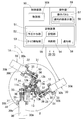
この発明の一実施形態に係るリンク作動装置の診断装置の概念構成のブロック図とリンク作動装置の水平断面とを示す説明図である。
同実施形態の一部を変更したリンク作動装置の診断装置の概念構成のブロック図とリンク作動装置の水平断面とを示す説明図である。
同実施形態の図2とは別の箇所を変更したリンク作動装置の診断装置の概念構成のブロック図とリンク作動装置の水平断面とを示す説明図である。
同リンク作動装置の一つのリンク機構のみを示す正面図である。
同リンク作動装置を図4とは異なる動作状態で示す正面図である。
同リンク作動装置のリンク機構部の斜視図である。
同リンク作動装置の一つのリンク機構を示す模式図である。
同リンク作動装置の部分拡大断面図である。
同リンク作動装置の診断装置が行う処理動作の流れ図である。
同リンク作動装置の診断装置におけるイニシャライズ処理後の処理動作の例を示す流れ図である。
同リンク作動装置の診断装置におけるイニシャライズ処理後の処理動作の他の例を示す流れ図である。
同診断装置の制御対象となるリンク作動装置の他の例を示す水平断面図である。
同リンク作動装置につき一つのリンク機構を示す正面図である。
同リンク作動装置の斜視図である。
同診断装置の制御対象となるパラレルリンク機構のさらに他の例を示す水平断面図である。
同パラレルリンク機構の部分拡大水平断面図である。
同リンク作動装置の異常発生部を含む場合の各軸のモータトルク変動を示すグラフである。
The present invention will be more clearly understood from the following description of preferred embodiments with reference to the accompanying drawings. However, the embodiments and drawings are for illustration and description only and should not be used to define the scope of the present invention. The scope of the invention is defined by the appended claims. In the accompanying drawings, the same reference numerals in a plurality of drawings indicate the same or corresponding parts.
It is explanatory drawing which shows the block diagram of the conceptual structure of the diagnostic apparatus of the link actuator which concerns on one Embodiment of this invention, and the horizontal cross section of a link actuator. It is explanatory drawing which shows the block diagram of the conceptual structure of the diagnostic apparatus of the link operating device which changed a part of same embodiment, and the horizontal cross section of a link operating device. It is explanatory drawing which shows the block diagram of the conceptual structure of the diagnostic apparatus of the link operating device which changed the location different from FIG. 2 of the embodiment, and the horizontal cross section of a link operating device. It is a front view showing only one link mechanism of the link actuating device. It is a front view which shows the same link action | operation apparatus in the operation state different from FIG. It is a perspective view of the link mechanism part of the link actuator. It is a mimetic diagram showing one link mechanism of the link actuating device. It is a partial expanded sectional view of the link actuating device. It is a flowchart of the processing operation which the diagnostic apparatus of the link operation device performs. It is a flowchart which shows the example of the processing operation after the initialization process in the diagnostic apparatus of the link actuating device. It is a flowchart which shows the other example of the processing operation after the initialization process in the diagnostic apparatus of the link actuating device. It is a horizontal sectional view showing other examples of a link actuating device used as a controlled object of the diagnostic device. It is a front view which shows one link mechanism per the link action | operation apparatus. It is a perspective view of the link actuating device. It is a horizontal sectional view showing still another example of a parallel link mechanism that is a control target of the diagnostic apparatus. It is a partial expanded horizontal sectional view of the parallel link mechanism. It is a graph which shows the motor torque fluctuation | variation of each axis | shaft in case the abnormality generation part of the same link actuator is included.
この発明の一実施形態を図1~図11と共に説明する。このリンク作動装置の診断装置51は、リンク作動装置1を構成する部品の劣化状態や損傷を診断する装置である。診断対象となるリンク作動装置1は、パラレルリンク機構1Aと、このパラレルリンク機構1Aを制御する制御装置50とを備え、前記パラレルリンク機構1Aが診断対象となる。
An embodiment of the present invention will be described with reference to FIGS. The link actuating device diagnosis device 51 is a device for diagnosing the deterioration state and damage of the parts constituting the link actuating device 1. The link actuating device 1 to be diagnosed includes a parallel link mechanism 1A and a control device 50 that controls the parallel link mechanism 1A, and the parallel link mechanism 1A is a diagnosis target.
パラレルリンク機構1Aは、基端側のリンクハブ14に対し先端側のリンクハブ15が、3組のリンク機構11,12,13を介して姿勢を変更可能に連結され、前記各リンク機構11,12,13は、それぞれ前記基端側のリンクハブ14および先端側のリンクハブ15に一端が回転可能に連結された基端側および先端側の端部リンク部材11a,12a,13a,11c,12c,13cと、これら基端側および先端側の端部リンク部材11a,12a,13a,11c,12c,13cの他端に両端がそれぞれ回転可能に連結された中央リンク部材11b,12b,13bとでなる。前記3組のリンク機構11,12,13の全てに前記基端側のリンクハブ14に対する前記先端側のリンクハブ15の姿勢である先端姿勢を任意に変更させる電動式のアクチュエータ30が設けられている。
In the parallel link mechanism 1A, a distal end side link hub 15 is connected to a proximal end side link hub 14 via three sets of link mechanisms 11, 12, and 13 so that the posture can be changed. Reference numerals 12 and 13 denote base end side and front end side end link members 11a, 12a, 13a, 11c, and 12c, respectively, one end of which is rotatably connected to the base end side link hub 14 and the front end side link hub 15. , 13c, and central link members 11b, 12b, 13b whose both ends are rotatably connected to the other ends of the end link members 11a, 12a, 13a, 11c, 12c, 13c on the proximal end side and the distal end side, respectively. Become. All of the three sets of link mechanisms 11, 12, and 13 are provided with electric actuators 30 that arbitrarily change the distal end posture of the distal end side link hub 15 relative to the proximal end side link hub 14. Yes.
図1において、前記アクチュエータ30は、例えばロータリアクチュエータ、より詳しくはモータ30aと減速機30bとで構成されるサーボモータであって、モータ固定部材32により基台2に固定されている。減速機構31は、アクチュエータ30の前記減速機30bと、歯車式の減速部33とでなる。
In FIG. 1, the actuator 30 is, for example, a rotary actuator, more specifically a servo motor including a motor 30 a and a speed reducer 30 b, and is fixed to the base 2 by a motor fixing member 32. The speed reduction mechanism 31 includes the speed reducer 30 b of the actuator 30 and a gear type speed reduction unit 33.
前記制御装置50は、上位制御手段(図示せず)からの位置指令等の指示により、または操作盤59からの位置指令等の入力操作に従ってパラレルリンク機構1Aの前記各アクチュエータ30のモータ30aを制御部50aで制御する装置である。前記位置指令は、例えば、先端側リンクハブ15の移動先の座標値等を示す指令である。前記制御部50aは、位置フィードバックの機能を備えた各軸(各アクチュエータ30)のサーボ機構を構成する。
The control device 50 controls the motor 30a of each actuator 30 of the parallel link mechanism 1A according to an instruction such as a position command from a host control means (not shown) or according to an input operation such as a position command from the operation panel 59. This is a device controlled by the unit 50a. The position command is, for example, a command indicating the coordinate value of the movement destination of the distal end side link hub 15 or the like. The controller 50a constitutes a servo mechanism for each axis (each actuator 30) having a position feedback function.
前記診断装置51につき説明する。この診断装置51は前記制御装置50に設けられている。なお、パラレルリンク機構1Aのより具体的な構成は、後に説明する。前記診断装置51は、予圧付与部52、トルク検知部53、判断部54、および通知部56によって構成される。
The diagnostic device 51 will be described. The diagnostic device 51 is provided in the control device 50. A more specific configuration of the parallel link mechanism 1A will be described later. The diagnostic device 51 includes a preload application unit 52, a torque detection unit 53, a determination unit 54, and a notification unit 56.
予圧付与部52は、前記各アクチュエータ30のモータ30aを駆動させて初期姿勢に位置決めし、前記リンク作動装置1に予圧を付与する手段である。この予圧付与の指令は前記制御部50aに与え、制御部50aが実行する。前記初期姿勢は任意に定めれば良く、リンク作動装置1の診断に適した姿勢、例えば前記予圧を与え易い姿勢等を選んで定められる。前記予圧付与部52により前記予圧を付与する動作は、このリンク作動装置1を前記初期姿勢とし、前記リンク作動装置1を構成する要素のうち、前記アクチュエータ30の駆動で相対的に動く要素(例えば歯車や軸受)により構成される各回転対偶等の対偶部につき、この対偶部の遊び内で片側へ寄せようとする力を付与する動作である。
The preload applying section 52 is means for driving the motor 30a of each actuator 30 to position it in the initial posture and applying preload to the link operating device 1. The preload application command is given to the control unit 50a, which is executed by the control unit 50a. The initial posture may be determined arbitrarily, and may be determined by selecting a posture suitable for diagnosis of the link actuating device 1, for example, a posture in which the preload is easily applied. In the operation of applying the preload by the preload applying unit 52, the link operating device 1 is set to the initial posture, and among the elements constituting the link operating device 1, the elements relatively move by driving the actuator 30 (for example, This is an operation of applying a force to move toward one side within the play of the pair of parts, such as a rotating pair of gears and bearings.
前記トルク検知部53は、前記予圧が付与された前記位置決めの状態で前記各アクチュエータ30のモータ30aの駆動トルクを検知する手段である。駆動トルクの検知は、例えば各モータ30aの駆動回路に設けられた電流計(図示せず)で検知された電流値を検出すること等で行われる。
The torque detector 53 is means for detecting the driving torque of the motor 30a of each actuator 30 in the positioning state where the preload is applied. The detection of the driving torque is performed, for example, by detecting a current value detected by an ammeter (not shown) provided in the driving circuit of each motor 30a.
前記判断部54は、前記リンク作動装置1が所定の条件で所定の動作を行ったときの前記各アクチュエータ30の駆動トルクを前記トルク検知部53で検出したトルクが所定範囲内であるか否かを判断する手段である。前記所定範囲は、試験や設計によって適宜定められる。前記所定範囲は、設計等により適宜定められる。この所定範囲は、上限を示す閾値だけで定めても良い。前記判断部54は、前記所定の動作、所定の条件、測定結果の組み合わせを、複数種、例えばこのリンク作動装置1が定まった形態で動作される場合はその動作の種類数だけ記憶していても良く、またトルク測定による異常判定を行う場合の動作が定められた一または複数である場合は、その数だけを記憶しても良い。判定時は、該当する動作の種類を適宜の方法で選定し、その動作の測定値を用いて判定に用いる。
The determination unit 54 determines whether or not the torque detected by the torque detection unit 53 of the drive torque of each actuator 30 when the link actuating device 1 performs a predetermined operation under a predetermined condition is within a predetermined range. It is a means to judge. The predetermined range is appropriately determined by testing and design. The predetermined range is appropriately determined by design or the like. This predetermined range may be determined only by a threshold value indicating the upper limit. The determination unit 54 stores a combination of the predetermined operation, the predetermined condition, and the measurement result for a plurality of types, for example, the number of types of the operation when the link operating device 1 is operated in a predetermined form. In addition, when one or more operations are performed when performing abnormality determination by torque measurement, only that number may be stored. At the time of determination, the type of the corresponding operation is selected by an appropriate method, and the measured value of the operation is used for the determination.
前記所定の条件および所定の動作は任意に定めた条件、動作であっても良いが、例えば、前記所定の条件は、前記予圧が付与されていること、前記リンク作動装置1の先端側の端部リンク部材11c,12c,13cに作用する負荷が定められた範囲内であること、および同端部リンク部材の移動速度が定められた範囲内であることの少なくとも一つを含み、前記所定の動作が、前記リンク作動装置1が所定の経路を移動することであっても良い。前記リンク作動装置1が動作中であっても、前記したように構成部品が正常時にリンク作動装置1に所定の条件で所定の動作をさせて動作中の駆動トルクを予め測定して記憶しておき、同条件で同じ動作を実行中の駆動トルクと正常時トルクとを比較すれば、異常であるか否かの正しい判定が行える。なお、ここで言う「所定の動作の動作中」は、位置決め動作を含む。
The predetermined condition and the predetermined operation may be arbitrarily determined conditions and operations. For example, the predetermined condition may be that the preload is applied, the end of the link operating device 1 on the front end side. Including at least one of a load acting on the portion link members 11c, 12c, and 13c being within a predetermined range and a moving speed of the end link member being within a predetermined range, The operation may be that the link operating device 1 moves along a predetermined route. Even when the link actuating device 1 is in operation, as described above, when the component is normal, the link actuating device 1 is caused to perform a predetermined operation under a predetermined condition, and the driving torque during operation is measured and stored in advance. If the driving torque during execution of the same operation under the same conditions is compared with the normal torque, it can be correctly determined whether or not it is abnormal. Here, “during a predetermined operation” includes a positioning operation.
また、前記所定の条件が、前記予圧が付与されていることであり、前記所定の動作が、前記リンク作動装置1が位置決め状態とすることであっても良い。
Further, the predetermined condition may be that the preload is applied, and the predetermined operation may be that the link operating device 1 is in a positioning state.
前記通知部56は、前記判断部54の判断結果を通知内容表示部58に通知し、表示させる手段である。前記通知部56は、単に通知だけでなく、後に説明するように、条件に対応して通知を行うか否かの判断や、イニシャライズ等の指令を行う機能を備える。通知内容表示部58は、例えば前記制御装置50に付属する操作盤59における操作パネル57等で構成される。前記操作パネル57は、液晶表示装置等のタッチパネル等からなり、画像の表示と制御部50a等への入力操作とが行えるものであっても良い。
The notification unit 56 is a means for notifying the notification content display unit 58 of the determination result of the determination unit 54 and displaying it. The notification unit 56 includes not only a notification but also a function of determining whether to perform a notification in response to a condition and a command for initialization, as will be described later. The notification content display unit 58 includes, for example, an operation panel 57 in the operation panel 59 attached to the control device 50. The operation panel 57 may be a touch panel such as a liquid crystal display device, and may be capable of displaying an image and performing an input operation to the control unit 50a and the like.
この構成のリンク作動装置の診断装置51において、図2に示すように、記憶部55を設け、前記判断部54により前記所定範囲に対して所定範囲外と判断された「回数」を前記記憶部55に記憶し、前記通知部56は、前記所定範囲外と判断された「回数」が閾値を超えた場合に、前記通知とは異なる通知、例えば部品交換を促す通知を行うようにしても良い。
As shown in FIG. 2, the diagnostic device 51 of the link actuating device having this configuration includes a storage unit 55, and stores the “number of times” determined by the determination unit 54 to be outside the predetermined range with respect to the predetermined range. 55, the notification unit 56 may perform a notification different from the notification, for example, a notification for urging component replacement when the “number of times” determined to be out of the predetermined range exceeds a threshold value. .
また、判断対象として、前記「回数」による他に、「周期」を判断対象に用いても良い。すなわち、前記判断部54により前記所定範囲に対して所定範囲外と判断された「周期」を前記記憶部55に記憶し、前記通知部56は、前記所定範囲外と判断された「周期」が閾値よりも短くなった場合に、前記通知とは異なる通知、例えば部品交換を促す通知を行うようにしてもよい。換言すれば、前記通知部56は、前記所定範囲外と判断された周期が閾値未満である場合に、前記通知とは異なる通知を行うようにしてもよい。
In addition to the “number of times”, “cycle” may be used as a determination target. That is, the “cycle” determined by the determination unit 54 to be outside the predetermined range with respect to the predetermined range is stored in the storage unit 55, and the notification unit 56 has the “cycle” determined to be out of the predetermined range. When it becomes shorter than the threshold value, a notification different from the notification, for example, a notification for urging component replacement may be performed. In other words, the notification unit 56 may perform a notification different from the notification when the period determined to be out of the predetermined range is less than the threshold.
前記通知内容表示部58は、図3に示すように、制御装置50とは離れた位置に設けられていても良い。例えば、このリンク作動装置1が設置された部屋とは別の集中管理室等に設けられていても良く、さらに広域の通信ネットワークを介して接続されたコンピュータ等の画像表示装置であっても良い。
The notification content display unit 58 may be provided at a position away from the control device 50 as shown in FIG. For example, it may be provided in a centralized management room or the like different from the room in which the link actuating device 1 is installed, or may be an image display device such as a computer connected via a wide-area communication network. .
前記構成の診断装置51の作用の概要を説明する。リンク作動装置1において、予めリンク作動装置1に予圧を付与すると、構成部品である歯車や軸受などに摩耗等の劣化が発生した場合に、予圧量が低下してリンク機構11~13を動かすアクチュエータ30のモータ30aのトルクが低下してしまう。すなわち、前記リンク作動装置1は3つのモータ30aが同期して動くことで位置決めを行っているため、構成部品が劣化すると、位置決め時にモータトルクが低下する。また、歯車部などに異物が入った際には位置決め時にトルクが上昇する。
The outline of the operation of the diagnostic apparatus 51 having the above-described configuration will be described. In the link actuating device 1, if preload is applied to the link actuating device 1 in advance, an actuator that moves the link mechanisms 11 to 13 by reducing the preload amount when deterioration such as wear occurs in a gear or a bearing as a component. The torque of the 30 motors 30a is reduced. That is, since the link operating device 1 performs positioning by the three motors 30a moving in synchronization, if the component parts deteriorate, the motor torque decreases during positioning. In addition, when foreign matter enters the gear portion or the like, the torque increases during positioning.
このことを利用し、このリンク作動装置1の診断装置51は、トルク検知部53でモータ30aのトルクを監視し、位置決め時の所定範囲を超えるトルク低下やトルクの増大を判断部54で検出した場合、タッチパネルなどの通知内容表示部58にトルク低下警告またはトルク増大警告等の通知を行う。トルク低下や増大が頻発した場合は、後述のように、前記通知内容表示部58に部品交換時期であることを通知する。
Utilizing this fact, the diagnostic device 51 of the link operating device 1 monitors the torque of the motor 30a by the torque detection unit 53, and detects the torque decrease and the torque increase exceeding the predetermined range at the time of positioning by the determination unit 54. In this case, a notification such as a torque reduction warning or a torque increase warning is given to the notification content display unit 58 such as a touch panel. When torque reduction or increase occurs frequently, the notification content display unit 58 is notified of the time for parts replacement, as will be described later.
このリンク作動装置1の診断装置51は、リンク作動装置1の組立後最初に動作させる前に、初期位置で基準となるトルクを設定するイニシャライズ処理を行う。例えばリンク作動装置1の先端側のリンクハブ15の姿勢が固定されるように、例えば器物への押し付け状態となるように、所定位置に位置決めする。その後の使用でモータ30aのトルクが前記所定範囲よりも上昇または低下した場合は、再度イニシャライズ処理を行うことで、新たに所定トルクを設定し直すことができる。
The diagnostic device 51 of the link actuating device 1 performs an initialization process for setting a reference torque at the initial position before the link actuating device 1 is operated for the first time after assembly. For example, the link hub 15 on the distal end side of the link actuating device 1 is positioned at a predetermined position so that the link hub 15 is pressed against a container, for example. When the torque of the motor 30a rises or falls below the predetermined range in subsequent use, the predetermined torque can be newly set again by performing initialization processing again.
所定の動作時間に対し、モータトルクの上昇/低下が頻発し、イニシャライズ処理を一定以上行った場合は、部品の劣化/異常と判断し、部品交換時であることの通知を行うことで、使用者に部品の交換を促す。歯車などが破損する前に使用者に部品交換時期であることを通知することで、装置が使用不可となる前に部品を交換することができるようになり、メンテナンス性が向上する。前記通知は、リンク作動装置1の操作盤59における操作パネル57に行うことで、使用者が気づきやすくなる。
When the motor torque frequently increases / decreases for a specified operating time and the initialization process is performed more than a certain level, it is judged that the part is deteriorated / abnormal, and it is used by notifying that the part is being replaced. Encourage people to replace parts. By notifying the user that it is time to replace the parts before the gears or the like are damaged, the parts can be replaced before the apparatus becomes unusable, improving the maintainability. The notification is given to the operation panel 57 of the operation panel 59 of the link operating device 1 so that the user can easily notice.
次に、前記構成の診断装置51の具体的な動作例を、図9~図11と共に説明する。図9において、図1の予圧付与部52からの指令により、制御部50aのモータサーボをオンにし(ステップR1)、所定の動作を実施する(ステップR2)。所定の動作は、定められた区間をリンク作動装置1の先端側のリンクハブ15が移動する動作であっても良く、また所定位置に位置決めする動作であっても良い。この所定の動作の完了、例えば前記定められた区間の終端まで移動したこと、または位置決めの完了が前記制御部50a等で検出されると、全モータ30aのトルクをトルク検知部53で測定する(ステップ3R)。
Next, a specific operation example of the diagnostic apparatus 51 having the above-described configuration will be described with reference to FIGS. In FIG. 9, the motor servo of the control unit 50a is turned on (step R1) according to a command from the preload applying unit 52 in FIG. 1, and a predetermined operation is performed (step R2). The predetermined operation may be an operation in which the link hub 15 on the distal end side of the link operating device 1 moves in a predetermined section, or may be an operation in which the link hub 15 is positioned at a predetermined position. When the completion of the predetermined operation, for example, the movement to the end of the predetermined section or the completion of positioning is detected by the control unit 50a or the like, the torque of all the motors 30a is measured by the torque detection unit 53 ( Step 3R).
判断部54は、全モータ30aにつき、トルクが所定範囲外であるかを判断し(ステップR4)、通知部56は、任意の数以上のモータ30aのトルクが所定範囲外であると、トルク異常の検知回数を計数するカウンタ(図示せず)がカウント値を1だけインクリメントし(ステップR5)、トルク異常の通知を行って通知内容表示部58に表示させる(ステップR6)。この段階ではリンク作動装置1の正常な動作がまだ行える可能性が高いからである。前記モータトルクの判定ステップR4で、所定範囲内のモータが任意の数以上あるときは、トルク異常の通知を行わない(R7)。
The determination unit 54 determines whether or not the torque is out of the predetermined range for all the motors 30a (step R4), and the notification unit 56 determines that the torque is abnormal if the torque of any number of motors 30a is out of the predetermined range. A counter (not shown) that counts the number of times of detection increments the count value by 1 (step R5), notifies the torque abnormality and displays it on the notification content display section 58 (step R6). This is because there is a high possibility that normal operation of the link operating device 1 can still be performed at this stage. In the motor torque determination step R4, when there are an arbitrary number or more of motors within the predetermined range, notification of torque abnormality is not performed (R7).
図10は、図2の記憶部55を備え、検知頻度で部品交換時期の通知を行う場合の流れを示す。トルク異常通知の表示中(ステップS1)に、イニシャライズ処理を行う(ステップS2)。このイニシャライズ処理は、初期位置での基準となるトルクの再設定である。全モータ30aのトルクを測定し(ステップS3)、任意の数以上のモータ30aのトルクが所定範囲外であるかを判断する(ステップS4)。任意の数以上のモータ30aのトルクが所定範囲内であると判断された場合はトルク異常通知を消去する(ステップS8)。
FIG. 10 shows a flow in the case where the storage unit 55 of FIG. 2 is provided and the part replacement time is notified at the detection frequency. While the torque abnormality notification is being displayed (step S1), an initialization process is performed (step S2). This initialization process is to reset the torque that serves as a reference at the initial position. The torques of all the motors 30a are measured (step S3), and it is determined whether the torques of an arbitrary number of motors 30a are outside a predetermined range (step S4). If it is determined that the torque of any number of motors 30a is within the predetermined range, the torque abnormality notification is deleted (step S8).
任意の数以上のモータ30aのトルクが所定範囲外であると判断された場合は、トルク異常の検知回数を計数するカウンタ(図示せず)のカウント値を1だけインクリメントする(ステップS5)。このインクリメントされたトルク検知回数が規定数を超えたか否かを判断し(ステップS6)、超えていない場合はトルク異常通知を表示する(ステップS9)。前記判断ステップS6で超えたと判断された場合は、部品交換時期通知を前記通知内容表示部58に表示する(ステップS7)。
If it is determined that the torque of an arbitrary number of motors 30a is out of the predetermined range, the count value of a counter (not shown) that counts the number of detected torque abnormalities is incremented by 1 (step S5). It is determined whether or not the incremented number of times of torque detection exceeds a specified number (step S6), and if not, a torque abnormality notification is displayed (step S9). If it is determined in the determination step S6 that a part has been exceeded, a part replacement time notification is displayed on the notification content display unit 58 (step S7).
このような一連の処理により、リンク作動装置1を構成する部品(歯車や軸受など)が部品交換時期にあるか否かを判断し、部品交換時期通知を適切に行うことができる。
By such a series of processes, it is possible to determine whether or not the parts (gears, bearings, etc.) constituting the link operating device 1 are in the part replacement time, and appropriately notify the part replacement time.
図11は、部品交換時期通知を、トルク異常周期の長さによって判断する場合を示す。まず、イニシャライズ処理(初期位置での基準となるトルクの再設定)を行う(ステップT1)。この後、トルク異常周期の計測を開始し(ステップT2)、制御部50aによるモータサーボをオンにする(ステップT3)。これにより所定の動作(所定区間の移動または位置決めなど)を実施し(ステップT4)、所定の動作が完了すると、全モータ30aのトルク測定を行う(ステップT5)。
FIG. 11 shows a case where the part replacement time notification is determined based on the length of the torque abnormality cycle. First, initialization processing (reset of a reference torque at the initial position) is performed (step T1). Thereafter, measurement of an abnormal torque period is started (step T2), and the motor servo by the control unit 50a is turned on (step T3). As a result, a predetermined operation (such as movement or positioning in a predetermined section) is performed (step T4). When the predetermined operation is completed, the torque of all the motors 30a is measured (step T5).
リンク作動装置1に異常発生部がある場合は、図9に試験例の3軸のトルク変動を示すように、正常時と比較して複数軸同時にトルク差が発生することが多い。そこで、前記全モータ30aのうち、任意の数以上のモータ30aのトルクが所定範囲外であるかを判断するようにしており(ステップT6)、任意の数以上のモータ30aのトルクが所定範囲内である場合は、トルク異常周期の計測を継続し(ステップT11)、前記モータサーボオンのステップT3に戻る。
When there is an abnormality occurrence part in the link actuating device 1, as shown in FIG. 9 showing torque fluctuations of the three axes in the test example, a torque difference often occurs at the same time for a plurality of axes compared to the normal state. Therefore, it is determined whether or not the torque of any number or more of the motors 30a out of the predetermined range among all the motors 30a (step T6), and the torque of any number or more of the motors 30a is within the predetermined range. If this is the case, the measurement of the abnormal torque period is continued (step T11), and the process returns to the motor servo-on step T3.
なお、図17は前記異常発生部がある場合のモータ30a(モータ1~3)のトルクの変化の一例を、正常なトルク変化と共に示すグラフである。
FIG. 17 is a graph showing an example of a change in torque of the motor 30a (motors 1 to 3) when there is the abnormality occurrence portion, along with a normal change in torque.
任意の数以上のモータ30aのトルクが所定範囲外である場合は、トルク異常通知を表示し(ステップT7)、トルク異常周期を記憶し(ステップT8)、その後にトルク異常周期が規定周期未満であるか否かを判断する(ステップT9)。前記規定周期は、設計により適宜の値に定めておく。規定周期以上である場合は、トルク異常周期の計測をリセットし(ステップT12)、イニシャライズ処理のステップT1に戻る。規定周期未満である場合は、部品交換時期の通知を表示する(ステップT10)。
When the torque of any number of motors 30a is out of the predetermined range, a torque abnormality notification is displayed (step T7), the torque abnormality period is stored (step T8), and the torque abnormality period is less than the specified period thereafter. It is determined whether or not there is (step T9). The specified period is set to an appropriate value by design. If it is longer than the specified period, the measurement of the torque abnormality period is reset (step T12), and the process returns to step T1 of the initialization process. If it is less than the specified period, a notification of the parts replacement time is displayed (step T10).
これら図10または図11に示した処理を行うようにした場合は、歯車や歯車のような部品などが破損する前に使用者に部品交換時期であることを高い信頼度で通知でき、これにより、装置が使用不可となる前に部品を交換することができるようになり、メンテナンス性がより一層向上する。
When the processing shown in FIG. 10 or FIG. 11 is performed, it is possible to notify the user that it is time to replace the parts with high reliability before the parts such as gears and gears are damaged. The parts can be replaced before the apparatus becomes unusable, and the maintainability is further improved.
次に、前記リンク作動装置1の具体的な構成例を説明する。図1および図4に示すように、このリンク作動装置1は、基台2に対して、リンク機構部3を介して、医療用器具等が取付けられる先端取付部材4(図4)を姿勢変更可能に連結したものである。リンク機構部3は、基台2にスペーサ5を介して固定された基端側のリンクハブ14と、先端取付部材4に固定された先端側のリンクハブ15と、これら基端側のリンクハブ14と先端側のリンクハブ15とを連結する3組のリンク機構11,12,13(以下、「11~13」と表記する場合がある)とを有する。なお、図4では、1組のリンク機構11のみを表示している。
Next, a specific configuration example of the link operating device 1 will be described. As shown in FIG. 1 and FIG. 4, the link actuating device 1 changes the posture of a tip mounting member 4 (FIG. 4) to which a medical instrument or the like is attached to a base 2 via a link mechanism portion 3. It is connected as possible. The link mechanism section 3 includes a base end side link hub 14 fixed to the base 2 via a spacer 5, a front end side link hub 15 fixed to the front end mounting member 4, and these base end side link hubs. 14 and three link mechanisms 11, 12, and 13 (hereinafter sometimes referred to as “11 to 13”) that connect the link hub 15 to the distal end side link hub 15. In FIG. 4, only one set of link mechanisms 11 is displayed.
図6は、リンク作動装置1のリンク機構部3の斜視図である。このリンク機構部3を構成する各リンク機構11,12,13は、基端側の端部リンク部材11a,12a,13a(以下、「11a~13a」と表記する)、中央リンク部材11b,12b,13b(以下、「11b~13b」と表記する)、および先端側の端部リンク部材11c,12c,13c(以下、「11c~13c」と表記する)で構成され、4つの回転対偶からなる3節連鎖のリンク機構をなす。基端側および先端側の端部リンク部材11a~13a,11c~13cはL字状をなし、基端がそれぞれの基端側のリンクハブ14および先端側のリンクハブ15に回転自在に連結されている。中央リンク部材11b~13bは、両端に基端側および先端側の端部リンク部材11a~13a,11c~13cの先端がそれぞれ回転自在に連結されている。
FIG. 6 is a perspective view of the link mechanism unit 3 of the link operating device 1. Each of the link mechanisms 11, 12, and 13 constituting the link mechanism unit 3 includes end-side end link members 11a, 12a, and 13a (hereinafter referred to as “11a to 13a”), and center link members 11b and 12b. , 13b (hereinafter referred to as “11b to 13b”), and end link members 11c, 12c, and 13c (hereinafter referred to as “11c to 13c”) on the distal end side, and are composed of four rotating pairs. It forms a three-bar chain link mechanism. The end link members 11a to 13a and 11c to 13c on the base end side and the tip end side are L-shaped, and the base ends are rotatably connected to the link hub 14 on the base end side and the link hub 15 on the tip end side. ing. The central link members 11b to 13b are rotatably connected to the distal ends of the end link members 11a to 13a and 11c to 13c on the proximal end side and the distal end side, respectively.
基端側および先端側の端部リンク部材11a~13a,11c~13cは球面リンク構造で、3組のリンク機構11~13における球面リンク中心PA,PC(図4、図5)は一致しており、また、その球面リンク中心PA,PCからの距離も同じである。端部リンク部材11a~13a,11c~13cと中央リンク部材11b~13bとの連結部となる回転対偶軸は、ある交差角をもっていてもよいし、平行であってもよい。
The end link members 11a to 13a and 11c to 13c on the proximal end side and the distal end side have a spherical link structure, and the spherical link centers PA and PC (FIGS. 4 and 5) in the three sets of link mechanisms 11 to 13 coincide with each other. The distances from the spherical link centers PA and PC are also the same. The rotational couple axes that are the connecting portions of the end link members 11a to 13a, 11c to 13c and the central link members 11b to 13b may have a certain crossing angle or may be parallel to each other.
つまり、3組のリンク機構11~13は、幾何学的に同一形状をなす。幾何学的に同一形状とは、各リンク部材11a~13a,11b~13b,11c~13cを直線で表現した幾何学モデルが、中央リンク部材11b~13bの中央部に対する基端側部分と先端側部分が対称を成す形状であることを言う。図7は、一つのリンク機構11を直線で模式的に表現した図である。
That is, the three sets of link mechanisms 11 to 13 have the same geometric shape. The geometrically identical shape means that a geometric model in which each link member 11a to 13a, 11b to 13b, 11c to 13c is expressed by a straight line is a proximal end portion and a distal end side with respect to the central portion of the central link members 11b to 13b. Says that the part is symmetrical. FIG. 7 is a diagram schematically representing one link mechanism 11 with a straight line.
この実施形態のリンク機構11~13は回転対称タイプで、基端側のリンクハブ14および基端側の端部リンク部材11a~13aと、先端側のリンクハブ15および先端側の端部リンク部材11c~13cとの位置関係が、中央リンク部材11b~13bの中心軸A(図6)に対して回転対称となる位置構成になっている。図4は、基端側のリンクハブ14の中心軸Bと先端側のリンクハブ15の中心軸Cとが同一線上にある状態を示し、図5は、基端側のリンクハブ14の中心軸Bに対して先端側のリンクハブ15の中心軸Cが所定の作動角をとった状態を示す。各リンク機構11~13の姿勢が変化しても、基端側と先端側の球面リンク中心PA,PC間の距離Dは変化しない。
The link mechanisms 11 to 13 of this embodiment are of a rotationally symmetric type, and include a base end side link hub 14 and a base end side end link member 11a to 13a, a front end side link hub 15 and a front end side end link member. The positional relationship with 11c to 13c is a position configuration that is rotationally symmetric with respect to the central axis A (FIG. 6) of the central link members 11b to 13b. 4 shows a state in which the central axis B of the link hub 14 on the proximal end side and the central axis C of the link hub 15 on the distal end side are collinear, and FIG. 5 shows the central axis of the link hub 14 on the proximal end side. A state in which the central axis C of the link hub 15 on the distal end side has taken a predetermined operating angle with respect to B is shown. Even if the postures of the link mechanisms 11 to 13 are changed, the distance D between the spherical link centers PA and PC on the proximal end side and the distal end side does not change.
基端側のリンクハブ14および先端側のリンクハブ15は六角柱状で、外周面を構成する6つの側面16(図6)のうちの1つ置きに離れた3つの側面16に、基端側および先端側の端部リンク部材11a~13a,11c~13cがそれぞれ回転自在に連結されている。
The link hub 14 on the proximal end side and the link hub 15 on the distal end side are hexagonal columnar, and the proximal side of the three side faces 16 apart from every other one of the six side faces 16 (FIG. 6) constituting the outer peripheral surface. The end link members 11a to 13a and 11c to 13c on the front end side are rotatably connected to each other.
図1の下部は、基端側のリンクハブ14と基端側の端部リンク部材11a~13aの連結部を示す横断面図、図8はその部分拡大図である。基端側のリンクハブ14の側面16(図6)から軸部18(図8)が突出し、この軸部18に複列の軸受17(図6)の内輪(図示せず)が外嵌し、基端側の端部リンク部材11a~13aの基端側のリンクハブ側の端部に軸受17の外輪(図示せず)が内嵌している。つまり、内輪は基端側のリンクハブ14に固定され、外輪が基端側の端部リンク部材11a~13aと共に回転する構造である。軸受17は、例えば深溝玉軸受、アンギュラ玉軸受等の玉軸受であって、ナット19による締付けでもって所定の予圧量を付与して固定されている。軸受17としては、図示例のように玉軸受を複列で配列する以外に、ローラ軸受や滑り軸受を用いてもよい。先端側のリンクハブ15と先端側の端部リンク部材11c~13cの連結部も、同様の構造である。
1 is a cross-sectional view showing a connecting portion between the base end side link hub 14 and the base end side end link members 11a to 13a, and FIG. 8 is a partially enlarged view thereof. A shaft portion 18 (FIG. 8) protrudes from a side surface 16 (FIG. 6) of the link hub 14 on the proximal end side, and an inner ring (not shown) of a double row bearing 17 (FIG. 6) is fitted on the shaft portion 18. An outer ring (not shown) of the bearing 17 is fitted into the end portion of the base end side link hub 11a to 13a on the base end side link hub side. That is, the inner ring is fixed to the link hub 14 on the base end side, and the outer ring rotates with the end link members 11a to 13a on the base end side. The bearing 17 is a ball bearing such as a deep groove ball bearing or an angular ball bearing, for example, and is fixed by applying a predetermined amount of preload by tightening with a nut 19. As the bearing 17, a roller bearing or a sliding bearing may be used in addition to the ball bearings arranged in a double row as in the illustrated example. The connecting portion between the link hub 15 on the distal end side and the end link members 11c to 13c on the distal end side has the same structure.
また、基端側の端部リンク部材11a~13aと中央リンク部材11b~13bの連結部も、複列の軸受20を介して互いに回転自在に連結されている。すなわち、基端側の端部リンク部材11a~13aに軸受20の外輪(図示せず)が内嵌し、中央リンク部材11b~13bに設けた軸部21に軸受20の内輪(図示せず)が外嵌している。なお、図1および図8では、基端側の端部リンク部材11aと中央リンク部材11bの連結部についてのみ図示されている。軸受20は、例えば深溝玉軸受、アンギュラ玉軸受等の玉軸受であって、ナット22による締付けでもって所定の予圧量を付与して固定されている。軸受20としては、図示例のように玉軸受を複列で配列する以外に、ローラ軸受や滑り軸受を用いてもよい。先端側の端部リンク部材11c~13cと中央リンク部材11b~13bの連結部も、同様の構造である。
Further, the connecting portions of the end link members 11a to 13a and the central link members 11b to 13b on the base end side are also rotatably connected to each other via the double row bearings 20. That is, the outer ring (not shown) of the bearing 20 is fitted into the end link members 11a to 13a on the base end side, and the inner ring (not shown) of the bearing 20 is fitted to the shaft portion 21 provided on the central link members 11b to 13b. Is fitted. In FIGS. 1 and 8, only the connecting portion between the end link member 11a on the base end side and the central link member 11b is shown. The bearing 20 is, for example, a ball bearing such as a deep groove ball bearing or an angular ball bearing, and is fixed by applying a predetermined amount of preload by tightening with a nut 22. As the bearing 20, a roller bearing or a sliding bearing may be used in addition to the ball bearings arranged in a double row as in the illustrated example. The connecting portions of the end-side end link members 11c to 13c and the central link members 11b to 13b have the same structure.
図6に示す前記リンク機構11~13において、基端側および先端側のリンクハブ14,15の軸部18(図8)の角度、長さ、および端部リンク部材11a~13a,11c~13cの幾何学的形状が基端側のリンクハブ14と先端側のリンクハブ15とで等しく、また、中央リンク部材11b~13bについても基端側のリンクハブ14と先端側のリンクハブ14とで形状が等しいとき、中央リンク部材11b~13bの対称面に対して中央リンク部材11b~13bと、基端側および先端側のリンクハブ14,15と連結される端部リンク部材11a~13a,11c~13cとの角度位置関係を基端側と先端側で同じにすれば、幾何学的対称性から基端側のリンクハブ14および基端側の端部リンク部材11a~13aと、先端側のリンクハブ15および先端側の端部リンク部材11c~13cとは同じに動く。例えば、基端側および先端側のリンクハブ14,15にそれぞれ中心軸B,Cと同軸に回転軸を設け、基端側のリンクハブ14から先端側のリンクハブ15へ回転伝達を行う場合、基端側のリンクハブ14と先端側のリンクハブ15は同じ回転角になって等速で回転する等速自在継手となる。この等速回転するときの中央リンク部材11b~13bの対称面を等速二等分面という。
In the link mechanisms 11 to 13 shown in FIG. 6, the angle and length of the shaft portion 18 (FIG. 8) of the link hubs 14 and 15 on the proximal end side and the distal end side, and the end link members 11a to 13a and 11c to 13c. The geometrical shapes of the link hub 14 on the proximal end side and the link hub 15 on the distal end side are the same, and the central link members 11b to 13b also have the same relationship between the link hub 14 on the proximal end side and the link hub 14 on the distal end side. When the shapes are equal, the end link members 11a to 13a and 11c are connected to the center link members 11b to 13b and the base end side and front end side link hubs 14 and 15 with respect to the symmetry plane of the center link members 11b to 13b. If the angular positional relationship with .about.13c is made the same between the base end side and the tip end side, the base end side link hub 14 and the base end side end link members 11a to 13a and the tip end side are considered from geometric symmetry. Move same as the end link members 11c ~ 13c of the link hub 15 and distal. For example, when the rotation shafts are provided coaxially with the central axes B and C on the link hubs 14 and 15 on the proximal end side and the distal end side, respectively, and the rotation is transmitted from the link hub 14 on the proximal end side to the link hub 15 on the distal end side. The link hub 14 on the proximal end side and the link hub 15 on the distal end side form a constant velocity universal joint that rotates at a constant speed at the same rotation angle. The plane of symmetry of the central link members 11b to 13b when rotating at the same speed is referred to as an equal speed bisector.
このため、基端側のリンクハブ14および先端側のリンクハブ15を共有する同じ幾何学形状のリンク機構11~13を円周上に複数配置させることにより、複数のリンク機構11~13が矛盾なく動ける位置として中央リンク部材11b~13bが等速二等分面上のみの動きに限定され、これにより基端側のリンクハブ14と先端側のリンクハブ15とは任意の作動角をとっても等速回転が得られる。
For this reason, by arranging a plurality of link mechanisms 11 to 13 having the same geometric shape sharing the proximal end side link hub 14 and the distal end side link hub 15 on the circumference, the plurality of link mechanisms 11 to 13 are contradictory. The central link members 11b to 13b are limited to movements on the equally-divided bisection plane as a position where they can move without any problem, so that the link hub 14 on the proximal end side and the link hub 15 on the distal end side can take any operating angle. Fast rotation is obtained.
各リンク機構11~13における4つの回転対偶の回転部、つまり、基端側のリンクハブ14と基端側の端部リンク部材11a~13aとの連結部分、先端側のリンクハブ15と先端側の端部リンク部材11c~13cとの連結部分、および基端側および先端側の端部リンク部材11a~13a,11c~13cと中央リンク部材11b~13bとの2つの連結部分を軸受構造とすることにより、その連結部分での摩擦抵抗を抑えて回転抵抗の軽減を図ることができ、滑らかな動力伝達を確保できると共に耐久性を向上できる。
The rotating parts of the four rotary pairs in each of the link mechanisms 11 to 13, that is, the connecting portion between the base end side link hub 14 and the base end side end link members 11a to 13a, the front end side link hub 15 and the front end side The bearing portion has a coupling portion with the end link members 11c to 13c and two coupling portions of the end link members 11a to 13a, 11c to 13c on the base end side and the distal end side and the central link members 11b to 13b. As a result, the frictional resistance at the connecting portion can be suppressed to reduce the rotational resistance, and smooth power transmission can be ensured and the durability can be improved.
このリンク機構部3の構成によれば、基端側のリンクハブ14に対する先端側のリンクハブ15の可動範囲を広くとれる。例えば、基端側のリンクハブ14の中心軸B(図6)と先端側のリンクハブ15の中心軸Cの折れ角θの最大値(最大折れ角)を約±90°とすることができる。また、基端側のリンクハブ14に対する先端側のリンクハブ15の旋回角φを0°~360°の範囲で設定できる。折れ角θは、基端側のリンクハブ14の中心軸Bに対して先端側のリンクハブ15の中心軸Cが傾斜した垂直角度のことであり、旋回角φは、基端側のリンクハブ14の中心軸Bに対して先端側のリンクハブ15の中心軸Cが傾斜した水平角度のことである。
According to the structure of the link mechanism section 3, the movable range of the link hub 15 on the distal end side with respect to the link hub 14 on the proximal end side can be widened. For example, the maximum value (maximum bending angle) of the bending angle θ between the central axis B (FIG. 6) of the link hub 14 on the proximal end side and the central axis C of the link hub 15 on the distal end side can be about ± 90 °. . Further, the turning angle φ of the distal end side link hub 15 relative to the proximal end side link hub 14 can be set in a range of 0 ° to 360 °. The bending angle θ is a vertical angle at which the central axis C of the distal end side link hub 15 is inclined with respect to the central axis B of the proximal end side link hub 14, and the turning angle φ is the proximal end side link hub. 14 is a horizontal angle at which the central axis C of the link hub 15 on the distal end side is inclined with respect to the central axis B of 14.
前記3組のリンク機構11~13の全てに、アクチュエータ30および減速機構31が設けられている。以下、図1および図8と共に、リンク機構11に設けられたアクチュエータ30および減速機構31について説明するが、リンク機構12,13に設けられたものについても同じ構成である。
All of the three sets of link mechanisms 11 to 13 are provided with an actuator 30 and a speed reduction mechanism 31. Hereinafter, the actuator 30 and the speed reduction mechanism 31 provided in the link mechanism 11 will be described together with FIG. 1 and FIG. 8, but those provided in the link mechanisms 12 and 13 have the same configuration.
図1に示すように、アクチュエータ30はロータリアクチュエータ、より詳しくは減速機30b付きのサーボモータ30aであって、モータ固定部材32により基台2に固定されている。減速機構31は、アクチュエータ30の減速機30bと、歯車式の減速部33とでなる。
As shown in FIG. 1, the actuator 30 is a rotary actuator, more specifically, a servo motor 30a with a speed reducer 30b, and is fixed to the base 2 by a motor fixing member 32. The speed reduction mechanism 31 includes a speed reducer 30 b of the actuator 30 and a gear type speed reduction portion 33.
図8に示すように、歯車式の減速部33は、アクチュエータ30の出力軸30cにカップリング35を介して回転伝達可能に連結された小歯車36と、基端側の端部リンク部材11aに固定され前記小歯車36と噛み合う大歯車37とで構成されている。図示例では、小歯車36および大歯車37は平歯車であり、大歯車37は、扇形の周面にのみ歯が形成された扇形歯車である。大歯車37は小歯車36よりもピッチ円半径が大きく、アクチュエータ30の出力軸30cの回転が基端側の端部リンク部材11aへ、基端側のリンクハブ14と基端側の端部リンク部材11aの回転対偶軸O1回りの回転に減速して伝達される。その減速比は10以上とされている。
As shown in FIG. 8, the gear-type speed reducing portion 33 is connected to a small gear 36 connected to the output shaft 30 c of the actuator 30 via a coupling 35 so as to be able to transmit rotation, and a proximal end side end link member 11 a. The large gear 37 is fixed and meshed with the small gear 36. In the illustrated example, the small gear 36 and the large gear 37 are spur gears, and the large gear 37 is a sector gear in which teeth are formed only on the circumferential surface of the sector. The large gear 37 has a larger pitch circle radius than the small gear 36, and the rotation of the output shaft 30 c of the actuator 30 moves to the proximal end link member 11 a, and the proximal link hub 14 and the proximal end link It is decelerated and transmitted to the rotation of the member 11a around the rotation pair O1. The reduction ratio is 10 or more.
大歯車37のピッチ円半径は、基端側の端部リンク部材11aのアーム長Lの1/2以上としてある。前記アーム長Lは、基端側のリンクハブ14と基端側の端部リンク部材11aの回転対偶軸O1の軸方向中心点P1から、基端側の端部リンク部材11aと中央リンク部材11bの回転対偶軸O2の軸方向中心点P2を基端側のリンクハブ14と基端側の端部リンク部材11aの回転対偶軸O1に直交してその軸方向中心点P1を通る平面に投影した点P3までの距離である。この実施形態の場合、大歯車37のピッチ円半径が前記アーム長L以上である。そのため、高い減速比を得るのに有利である。
The pitch circle radius of the large gear 37 is set to 1/2 or more of the arm length L of the end link member 11a on the base end side. The arm length L is determined from the axial center point P1 of the rotation pair shaft O1 of the base end side link hub 14 and the base end side end link member 11a from the base end side end link member 11a and the central link member 11b. The axial center point P2 of the rotation pair O2 is projected onto a plane passing through the axial center point P1 perpendicular to the rotation pair axis O1 of the link hub 14 on the base end side and the end link member 11a on the base end side. This is the distance to the point P3. In the case of this embodiment, the pitch circle radius of the large gear 37 is not less than the arm length L. Therefore, it is advantageous to obtain a high reduction ratio.
小歯車36は、大歯車37と噛み合う歯部36aの両側に突出する軸部36bを有し、これら両軸部36bが、基台2に設置された回転支持部材39に設けられた複列の軸受40によりそれぞれ回転自在に支持されている。軸受40は、例えば深溝玉軸受、アンギュラ玉軸受等の玉軸受である。図示例のように玉軸受を複列で配列する以外に、ローラ軸受や滑り軸受を用いてもよい。複列の軸受40の各外輪(図示せず)間にはシム(図示せず)を設け、軸部36bに螺合したナット41を締め付けることにより、軸受40に予圧を付与する構成としてある。軸受40の外輪は、回転支持部材39に圧入されている。
The small gear 36 has shaft portions 36 b protruding on both sides of a tooth portion 36 a that meshes with the large gear 37, and both the shaft portions 36 b are arranged in a double row provided on a rotation support member 39 installed on the base 2. The bearings 40 are rotatably supported. The bearing 40 is a ball bearing such as a deep groove ball bearing or an angular ball bearing. In addition to arranging ball bearings in double rows as in the illustrated example, roller bearings or sliding bearings may be used. A shim (not shown) is provided between the outer rings (not shown) of the double row bearings 40, and a preload is applied to the bearing 40 by tightening a nut 41 screwed into the shaft portion 36b. The outer ring of the bearing 40 is press-fitted into the rotation support member 39.
大歯車37は、基端側の端部リンク部材11aと別部材であり、基端側の端部リンク部材11aに対してボルト等の結合具42により着脱可能に取付けられている。
The large gear 37 is a separate member from the base end side end link member 11a, and is detachably attached to the base end side end link member 11a by a coupler 42 such as a bolt.
アクチュエータ30の回転軸心O3および小歯車36の回転軸心O4は同軸上に位置する。これら回転軸心O3,O4は、基端側のリンクハブ14と基端側の端部リンク部材11aの回転対偶軸O1と平行で、かつ基台2からの高さが同じとされている。
The rotation axis O3 of the actuator 30 and the rotation axis O4 of the small gear 36 are located on the same axis. These rotation axes O3 and O4 are parallel to the rotation pair axis O1 of the base end side link hub 14 and the base end side end link member 11a and have the same height from the base 2.
図1において、制御装置50は、コンピュータによる数値制御式のものであり、前記制御装置50における制御部50aは、例えば折れ角θ(図6)および旋回角φ(図6)を規定することで、先端側のリンクハブ15の姿勢を設定する。また、例えばエンコーダ(図示せず)等により基端側の端部リンク部材11a~13aの回転角βn(図6におけるβ1,β2)を検出する。あるいはアクチュエータ30のエンコーダ(図示せず)を先端側のリンクハブ15の姿勢検出に用いても良い。折れ角θおよび旋回角φと、各回転角βnとは相互関係があり、一方の値から他方の値を導くことができる。
In FIG. 1, a control device 50 is of a numerical control type by a computer, and a control unit 50a in the control device 50 defines, for example, a bending angle θ (FIG. 6) and a turning angle φ (FIG. 6). The attitude of the link hub 15 on the distal end side is set. Further, the rotation angle βn (β1, β2 in FIG. 6) of the end-side end link members 11a to 13a is detected by, for example, an encoder (not shown). Or you may use the encoder (not shown) of the actuator 30 for the attitude | position detection of the link hub 15 of the front end side. The bending angle θ, the turning angle φ, and each rotation angle βn are mutually related, and the other value can be derived from one value.
基端側のリンクハブ14に対し先端側のリンクハブ15を姿勢変更する場合、制御部50aに設定された先端側のリンクハブ15の姿勢(または座標位置)に応じて、基端側の端部リンク部材11a~13aの回転角βnの制御目標値を計算する。上記回転角βnは、アクチュエータ30の動作位置を意味する。回転角βnの計算は、下記の式1を逆変換することで行われる。逆変換とは、折れ角θおよび旋回角φから基端側の端部リンク部材11a~13aの回転角βnを算出する変換のことである。
cos(θ/2)sinβn-sin(θ/2)sin(φ+δn)cosβn+sin(γ/2)=0 …(式1)
ここで、γ(図6)は、基端側の端部リンク部材11a~13aと中央リンク部材11b~13bの回転対偶軸O2と、先端側の端部リンク部材11c~13cと中央リンク部材11b~13bの回転対偶軸O5とが成す角度である。δn(図6におけるδ1,δ2,δ3)は、基準となる基端側の端部リンク部材11aに対する各基端側の端部リンク部材11a~13aの円周方向の離間角である。 When the posture of the distal endside link hub 15 is changed with respect to the proximal end side link hub 14, the proximal end side end is changed according to the posture (or coordinate position) of the distal end side link hub 15 set in the control unit 50a. The control target value of the rotation angle βn of the partial link members 11a to 13a is calculated. The rotation angle βn means the operating position of the actuator 30. The calculation of the rotation angle βn is performed by inversely transforming Equation 1 below. Inverse conversion is conversion in which the rotation angle βn of the end link members 11a to 13a on the base end side is calculated from the bending angle θ and the turning angle φ.
cos (θ / 2) sinβn−sin (θ / 2) sin (φ + δn) cosβn + sin (γ / 2) = 0 (Formula 1)
Here, γ (FIG. 6) is the rotation pair O2 of theend link members 11a to 13a and the central link members 11b to 13b on the proximal end side, the end link members 11c to 13c on the distal end side, and the central link member 11b. This is the angle formed by the rotation pair O5 of ~ 13b. δn (δ1, δ2, δ3 in FIG. 6) is a circumferential separation angle of each of the base end side end link members 11a to 13a with respect to the base end side end link member 11a.
cos(θ/2)sinβn-sin(θ/2)sin(φ+δn)cosβn+sin(γ/2)=0 …(式1)
ここで、γ(図6)は、基端側の端部リンク部材11a~13aと中央リンク部材11b~13bの回転対偶軸O2と、先端側の端部リンク部材11c~13cと中央リンク部材11b~13bの回転対偶軸O5とが成す角度である。δn(図6におけるδ1,δ2,δ3)は、基準となる基端側の端部リンク部材11aに対する各基端側の端部リンク部材11a~13aの円周方向の離間角である。 When the posture of the distal end
cos (θ / 2) sinβn−sin (θ / 2) sin (φ + δn) cosβn + sin (γ / 2) = 0 (Formula 1)
Here, γ (FIG. 6) is the rotation pair O2 of the
回転角βnの制御目標値を計算したなら、姿勢検出手段(図示せず)の信号を利用したフィードバック制御により、実際の回転角βnが制御目標値となるように各アクチュエータ30の出力を制御する。それにより、全てのリンク機構11~13の基端側の端部リンク部材11a~13aが定められた回転角βnだけ回転し、先端側のリンクハブ15が姿勢設定手段51により設定された姿勢に変更される。
Once the control target value of the rotation angle βn is calculated, the output of each actuator 30 is controlled so that the actual rotation angle βn becomes the control target value by feedback control using a signal from an attitude detection means (not shown). . As a result, the end link members 11a to 13a on the base end side of all the link mechanisms 11 to 13 are rotated by a predetermined rotation angle βn, and the link hub 15 on the distal end side is set to the posture set by the posture setting means 51. Be changed.
図12~図14は、前記診断装置51の診断対象となるパラレルリンク機構1A(図1)の別の具体例を示す。同図のパラレルリンク機構1Bは、図1~図8と共に説明した前記パラレルリンク機構1Aとは、基本的な構成な構成は同じである。すなわち、基端側のリンクハブ14に対し先端側のリンクハブ15が、3組以上のリンク機構11~13を介して姿勢を変更可能に連結され、前記各リンク機構11~13は、それぞれ前記基端側のリンクハブ14および先端側のリンクハブ15に一端が回転可能に連結された基端側および先端側の端部リンク部材11a,11c,12a,12c,13a,13cと、これら基端側および先端側の端部リンク部材の他端に両端がそれぞれ回転可能に連結された中央リンク部材11b,12b,13bとでなり、前記3組以上のリンク機構11~13の全てに前記基端側のリンクハブ14に対する前記先端側のリンクハブ15の姿勢である先端姿勢を任意に変更させる電動式のアクチュエータ30が設けられたという構成、および前記リンク機構11,12,13を直線で表現した幾何学モデルが、前記中央リンク部材11b,12b,13bの中央部に対する基端側部分と先端側部分とが対称を成す形状であると言う構成については同じである。
なお、特に説明した事項の他は、図1~図8に示したパラレルリンク機構1Aと同様である。 12 to 14 show another specific example of theparallel link mechanism 1A (FIG. 1) to be diagnosed by the diagnostic device 51. FIG. The parallel link mechanism 1B shown in the figure has the same basic configuration as the parallel link mechanism 1A described with reference to FIGS. That is, the link hub 15 on the distal end side is connected to the link hub 14 on the proximal end side through three or more sets of link mechanisms 11 to 13 so that the posture can be changed. Proximal and distal end link members 11a, 11c, 12a, 12c, 13a and 13c, one end of which is rotatably connected to the proximal link hub 14 and the distal link hub 15, and these proximal ends A central link member 11b, 12b, 13b having both ends rotatably connected to the other end of the end link member on the side and the front end side, and the base end is included in all of the three or more sets of link mechanisms 11-13. A configuration in which an electric actuator 30 for arbitrarily changing a distal end posture, which is a posture of the distal end side link hub 15 with respect to the side link hub 14, is provided, and the link Regarding the configuration in which the geometric model expressing the structures 11, 12, and 13 in a straight line has a shape in which the proximal end portion and the distal end portion are symmetrical with respect to the central portion of the central link members 11b, 12b, and 13b. The same.
Except for the matters specifically described, theparallel link mechanism 1A shown in FIGS. 1 to 8 is the same.
なお、特に説明した事項の他は、図1~図8に示したパラレルリンク機構1Aと同様である。 12 to 14 show another specific example of the
Except for the matters specifically described, the
図14に示すように、先端側のリンクハブ15は、中央部に円形の貫通孔60aを有する平板状の先端部材60と、この先端部材60の貫通孔60aの周囲に円周方向等配で設けられた3個の回転軸連結部材64とで構成される。貫通孔60aの中心は、先端側のリンクハブ中心軸QB上に位置する。各回転軸連結部材64は、軸心がリンクハブ中心軸QBと交差する回転軸72が回転自在に連結されている。このリンクハブ15の回転軸72に、先端側の端部リンク部材11c,12c,13cの一端が連結される。先端側の端部リンク部材11c,12c,13cの他端には、中央リンク部材11bの他端に回転自在に連結された回転軸75が連結される。リンクハブ15の回転軸72および中央リンク部材11bの回転軸75は、2個の軸受(図示せず)を介して回転軸連結部材64および中央リンク部材11b,12b,13bの他端にそれぞれ回転自在に連結されている。
As shown in FIG. 14, the link hub 15 on the distal end side has a flat plate-shaped distal end member 60 having a circular through hole 60 a at the center, and a circumferentially uniform distribution around the through hole 60 a of the distal end member 60. The three rotation shaft coupling members 64 are provided. The center of the through hole 60a is located on the link hub central axis QB on the distal end side. Each rotary shaft connecting member 64 is rotatably connected to a rotary shaft 72 whose axis intersects the link hub central axis QB. One end of each end link member 11c, 12c, 13c on the front end side is connected to the rotation shaft 72 of the link hub 15. A rotating shaft 75 that is rotatably connected to the other end of the central link member 11b is connected to the other ends of the end link members 11c, 12c, and 13c on the front end side. The rotation shaft 72 of the link hub 15 and the rotation shaft 75 of the central link member 11b rotate to the other ends of the rotation shaft connecting member 64 and the central link members 11b, 12b, and 13b via two bearings (not shown). It is connected freely.
図12ないし図14と共に、端部リンク部材11a,12a,13a,11c,12c,13cの構成について説明する。基端側および先端側の端部リンク部材11a,12a,13a,11c,12c,13cは同じ構成であるので、ここでは例示として基端側の端部リンク部材11aについて説明する。図12に示すように、パラレルリンク機構1Bは、端部リンク部材11aが、1つの湾曲部材61と、この湾曲部材61の両端の外径側の側面と内径側の側面にそれぞれ固定された計4つの回転軸支持部材62とで構成される。4つの回転軸支持部材62は同一形状である。
The configuration of the end link members 11a, 12a, 13a, 11c, 12c, and 13c will be described with reference to FIGS. Since the end link members 11a, 12a, 13a, 11c, 12c, and 13c on the proximal end side and the distal end side have the same configuration, the end link member 11a on the proximal end side will be described here as an example. As shown in FIG. 12, the parallel link mechanism 1B includes an end link member 11a fixed to one bending member 61 and the outer diameter side surface and the inner diameter side surface of both ends of the bending member 61, respectively. It is composed of four rotating shaft support members 62. The four rotating shaft support members 62 have the same shape.
端部リンク部材11aの一端の2つの回転軸支持部材62に支持された回転軸75に中央リンク部材11bが回転自在に連結され、他端の2つの回転軸支持部材62に支持された回転軸72に、基端側のリンクハブ14が回転自在に連結される。これら各回転自在な連結部位には、それぞれ転がり軸受等の軸受が介在している。
The central link member 11b is rotatably connected to the rotary shaft 75 supported by the two rotary shaft support members 62 at one end of the end link member 11a, and the rotary shaft is supported by the two rotary shaft support members 62 at the other end. The link hub 14 on the proximal end side is rotatably connected to 72. A bearing such as a rolling bearing is interposed in each of these rotatable connecting portions.
姿勢変更用のアクチュエータ30は、前記実施形態と同様に、モータ30aと減速機30bとでなり、その減速機30bの出力軸30cは、この出力軸30cの中心軸と直交する平面状のフランジ面63を有している。出力軸30cは、スペーサ65を介して、前記フランジ面で基端側の端部リンク部材11aの外径側の回転軸支持部材62にボルトで接続されている。
As in the above embodiment, the posture changing actuator 30 includes a motor 30a and a speed reducer 30b, and an output shaft 30c of the speed reducer 30b is a flat flange surface orthogonal to the central axis of the output shaft 30c. 63. The output shaft 30c is connected to the rotating shaft support member 62 on the outer diameter side of the end link member 11a on the proximal end side by a bolt via the spacer 65 via the spacer 65.
図15および図16は、前記診断装置51の診断対象となるパラレルリンク機構1A(図1)のさらに別の具体例を示す。同図のパラレルリンク機構1Cは、図1~図8と共に説明した前記パラレルリンク機構1Aとは、基本的な構成な構成は同じである。すなわち、基端側のリンクハブ14に対し先端側のリンクハブ15が、3組以上のリンク機構11~13を介して姿勢を変更可能に連結され、前記各リンク機構11~13は、それぞれ前記基端側のリンクハブ14および先端側のリンクハブ15に一端が回転可能に連結された基端側および先端側の端部リンク部材11a,12a,13a,11c,12c,13cと、これら基端側および先端側の端部リンク部材11a,12a,13a,11c,12c,13cの他端に両端がそれぞれ回転可能に連結された中央リンク部材11b,12b,13bとでなる。前記3組以上のリンク機構11~13の全てに前記基端側のリンクハブ14に対する前記先端側のリンクハブ15の姿勢である先端姿勢を任意に変更させる電動式のアクチュエータ30が設けられたという構成、および前記リンク機構11,12,13を直線で表現した幾何学モデルが、前記中央リンク部材11b,12b,13bの中央部に対する基端側部分と先端側部分とが対称を成す形状であると言う構成については同じである。なお、特に説明した事項の他は、図1~図8に示したパラレルリンク機構1Aと同様である。
15 and 16 show still another specific example of the parallel link mechanism 1A (FIG. 1) to be diagnosed by the diagnostic device 51. FIG. The parallel link mechanism 1C shown in the figure has the same basic configuration as the parallel link mechanism 1A described with reference to FIGS. That is, the link hub 15 on the distal end side is connected to the link hub 14 on the proximal end side through three or more sets of link mechanisms 11 to 13 so that the posture can be changed. Proximal and distal end link members 11a, 12a, 13a, 11c, 12c and 13c, one end of which is rotatably connected to the proximal link hub 14 and the distal link hub 15, and these proximal ends Central link members 11b, 12b, and 13b having both ends rotatably connected to the other ends of the end link members 11a, 12a, 13a, 11c, 12c, and 13c on the side and front end sides. All of the three or more sets of link mechanisms 11 to 13 are provided with electric actuators 30 for arbitrarily changing the distal end posture of the distal end side link hub 15 with respect to the proximal end side link hub 14. The configuration and the geometric model in which the link mechanisms 11, 12, and 13 are expressed by straight lines have a shape in which the proximal end portion and the distal end portion are symmetrical with respect to the central portion of the central link members 11b, 12b, and 13b. The configuration is the same. Except for the matters specifically described, the parallel link mechanism 1A shown in FIGS. 1 to 8 is the same.
図16は、基端側のリンクハブ14と基端側の端部リンク部材11a,12a,13aの回転対偶部、および基端側の端部リンク部材11a,12a,13aと中央リンク部材11b,12b,13bの回転対偶部を示す断面図である。基端側のリンクハブ14は、前記軸方向の貫通孔95と外周側とを連通する半径方向の連通孔81が円周方向3箇所に形成され、各連通孔81内に設けた二つの軸受82により軸部材83がそれぞれ回転自在に支持されている。軸部材83の外側端部は基端側のリンクハブ14から突出し、その突出ねじ部83aに基端側の端部リンク部材11aが結合され、ナット84によって締付け固定されている。
FIG. 16 shows the base end side link hub 14 and the base end side end link members 11a, 12a, 13a, and the base end side end link members 11a, 12a, 13a and the center link member 11b, It is sectional drawing which shows the rotation pair part of 12b, 13b. In the link hub 14 on the proximal end side, radial communication holes 81 communicating the axial through hole 95 and the outer peripheral side are formed at three locations in the circumferential direction, and two bearings provided in each communication hole 81 are provided. The shaft members 83 are rotatably supported by 82. The outer end portion of the shaft member 83 protrudes from the proximal-side link hub 14, and the proximal-side end link member 11 a is coupled to the protruding screw portion 83 a and is fastened and fixed by a nut 84.
前記軸受82は、例えば深溝玉軸受等の転がり軸受であり、その外輪(図示せず)が前記連通孔81の内周に嵌合し、その内輪(図示せず)が前記軸部材83の外周に嵌合している。外輪は止め輪85によって抜け止めされている。また、内輪と基端側の端部リンク部材11aの間には間座86が介在し、ナット84の締付力が基端側の端部リンク部材11aおよび間座86を介して内輪に伝達されて、軸受82に所定の予圧を付与している。
The bearing 82 is a rolling bearing such as a deep groove ball bearing, for example, and an outer ring (not shown) is fitted to the inner circumference of the communication hole 81, and an inner ring (not shown) is the outer circumference of the shaft member 83. Is fitted. The outer ring is retained by a retaining ring 85. Further, a spacer 86 is interposed between the inner ring and the base end side end link member 11a, and the tightening force of the nut 84 is transmitted to the inner ring via the base end side end link member 11a and the spacer 86. Thus, a predetermined preload is applied to the bearing 82.
基端側の端部リンク部材11aと中央リンク部材11bの回転対偶部は、中央リンク部材11bの両端に形成された連通孔88に二つの軸受89が設けられ、これら軸受89により、基端側の端部リンク部材11aの先端の軸部90が回転自在に支持されている。軸受89は、間座91を介して、ナット92によって締付け固定されている。
The rotating pair of the end link member 11a and the center link member 11b on the base end side is provided with two bearings 89 in communication holes 88 formed at both ends of the center link member 11b. A shaft portion 90 at the tip of the end link member 11a is rotatably supported. The bearing 89 is fastened and fixed by a nut 92 via a spacer 91.
前記軸受89は、例えば深溝玉軸受等の転がり軸受であり、その外輪(図示せず)が前記連通孔88の内周に嵌合し、その内輪(図示せず)が前記軸部90の外周に嵌合している。外輪は止め輪93によって抜け止めされている。軸部90の先端ねじ部90aに螺着したナット92の締付力が間座91を介して内輪に伝達されて、軸受89に所定の予圧を付与している。
The bearing 89 is a rolling bearing such as a deep groove ball bearing, for example, and an outer ring (not shown) is fitted to the inner circumference of the communication hole 88, and an inner ring (not shown) is the outer circumference of the shaft portion 90. Is fitted. The outer ring is retained by a retaining ring 93. The tightening force of the nut 92 screwed to the tip threaded portion 90 a of the shaft portion 90 is transmitted to the inner ring through the spacer 91, and a predetermined preload is applied to the bearing 89.
以上、基端側のリンクハブ14と基端側の端部リンク部材11aの回転対偶部、および基端側の端部リンク部材11aと中央リンク部材11bの回転対偶部について説明したが、先端側のリンクハブ15と先端側の端部リンク部材11cの回転対偶部、および先端側の端部リンク部材11cと中央リンク部材11bの回転対偶部も同じ構成である(図示省略)。
As described above, the rotation pair of the base end side link hub 14 and the base end side end link member 11a and the rotation end of the base end side link member 11a and the central link member 11b have been described. The rotation pair of the link hub 15 and the end link member 11c on the distal end side, and the rotation pair of the end link member 11c and the central link member 11b on the distal end side have the same configuration (not shown).
このように、各リンク機構11,12,13における4つの回転対偶部、つまり、基端側のリンクハブ14と基端側の端部リンク部材11a,12a,13aの回転対偶部、先端側のリンクハブ15と先端側の端部リンク部材11c,12c,13cの回転対偶部、基端側の端部リンク部材11a,12a,13aと中央リンク部材11b,12b,13bと回転対偶部、および先端側の端部リンク部材11c,12c,13cと中央リンク部材11b、12b,13bの回転対偶部に、軸受82,89を設けた構造とすることにより、各回転対偶での摩擦抵抗を抑えて回転抵抗の軽減を図ることができ、滑らかな動力伝達を確保できると共に耐久性を向上できる。
As described above, the four rotating pairs of the link mechanisms 11, 12, and 13; that is, the rotating pairs of the proximal-side link hub 14 and the proximal-side end link members 11a, 12a, and 13a, Rotating pair of link hub 15 and distal end side end link members 11c, 12c, 13c, proximal end side link members 11a, 12a, 13a and central link members 11b, 12b, 13b and rotated pair, and tip The bearings 82 and 89 are provided at the rotational pair portions of the end link members 11c, 12c, and 13c on the side and the central link members 11b, 12b, and 13b, so that the frictional resistance at each rotational pair is suppressed and rotated. Resistance can be reduced, smooth power transmission can be ensured and durability can be improved.
アクチュエータ30は、回転駆動すると、その回転が一対のかさ歯車96,97(図15)を介して軸部材83に伝達されて、基端側のリンクハブ14に対する基端側の端部リンク部材11a,12a,13aの角度が変更する。それにより、基端側のリンクハブ14に対する先端側のリンクハブ15の姿勢(以下、「先端姿勢」とする)が決まる。
When the actuator 30 is driven to rotate, the rotation is transmitted to the shaft member 83 via a pair of bevel gears 96 and 97 (FIG. 15), and the proximal end side end link member 11a with respect to the proximal end side link hub 14 is transmitted. , 12a, 13a change. Thereby, the posture of the link hub 15 on the distal end side with respect to the link hub 14 on the proximal end side (hereinafter referred to as “tip posture”) is determined.
前記実施形態で示したパラレルリンク機構1A~1Cは、いずれも、アクチュエータ30の駆動を伝達する経路でバックラッシやその他の遊びが生じる。そのため、前記実施形態の診断装置51で診断することにより、破損するなど、装置が使用不可となる前に、部品の劣化状態を精度良く診断して使用者に知らせることができ、メンテナンス性を向上させることができると言う利点が効果的に発揮される。
In any of the parallel link mechanisms 1A to 1C shown in the above embodiment, backlash and other play occur in the path for transmitting the drive of the actuator 30. Therefore, by diagnosing with the diagnostic device 51 of the above-mentioned embodiment, it is possible to accurately diagnose the deterioration state of the parts and inform the user before the device becomes unusable, such as breakage, improving the maintainability The advantage that it can be made effective is exhibited.
以上のとおり、図面を参照しながら好適な実施形態を説明したが、当業者であれば、この明細書を見て、自明な範囲内で種々の変更および修正を容易に想定するであろう。したがって、そのような変更および修正は、請求の範囲から定まる発明の範囲内のものと解釈される。
As described above, the preferred embodiments have been described with reference to the drawings. However, those skilled in the art will readily consider various changes and modifications within the obvious range by referring to this specification. Accordingly, such changes and modifications are to be construed as within the scope of the invention as defined by the appended claims.
1…リンク作動装置
1A,1B,1C…パラレルリンク機構
11,12,13…リンク機構
11a,12a,13a…基端側の端部リンク部材
11b,12b,13b…中央リンク部材
11c,12c,13c…先端側の端部リンク部材
14…基端側のリンクハブ
15…先端側のリンクハブ
30…アクチュエータ
31…減速機構
50…制御装置
52…予圧付与部
53…トルク検知部
54…判断部
55…記憶部
56…通知部
57…操作パネル
59…操作盤 DESCRIPTION OFSYMBOLS 1 ... Link operation apparatus 1A, 1B, 1C ... Parallel link mechanism 11, 12, 13 ... Link mechanism 11a, 12a, 13a ... End part link member 11b, 12b, 13b ... Central link member 11c, 12c, 13c on the base end side The distal end side link member 14 The proximal end side link hub 15 The distal end side link hub 30 The actuator 31 The speed reduction mechanism 50 The control device 52 The preload applying unit 53 The torque detecting unit 54 The determining unit 55 Storage unit 56 ... notification unit 57 ... operation panel 59 ... operation panel
1A,1B,1C…パラレルリンク機構
11,12,13…リンク機構
11a,12a,13a…基端側の端部リンク部材
11b,12b,13b…中央リンク部材
11c,12c,13c…先端側の端部リンク部材
14…基端側のリンクハブ
15…先端側のリンクハブ
30…アクチュエータ
31…減速機構
50…制御装置
52…予圧付与部
53…トルク検知部
54…判断部
55…記憶部
56…通知部
57…操作パネル
59…操作盤 DESCRIPTION OF
Claims (8)
- 基端側のリンクハブに対し先端側のリンクハブが、3組以上のリンク機構を介して姿勢を変更可能に連結され、前記各リンク機構は、それぞれ前記基端側のリンクハブおよび先端側のリンクハブに一端が回転可能に連結された基端側および先端側の端部リンク部材と、これら基端側および先端側の端部リンク部材の他端に両端がそれぞれ回転可能に連結された中央リンク部材とでなり、前記3組以上のリンク機構の全てに前記基端側のリンクハブに対する前記先端側のリンクハブの姿勢である先端姿勢を任意に変更させる姿勢制御用のアクチュエータが設けられたリンク作動装置における診断装置であって、
前記各アクチュエータを駆動させて前記リンク作動装置に予圧を付与する予圧付与部と、前記各アクチュエータの駆動トルクを検知するトルク検知部と、前記リンク作動装置が所定の条件で所定の動作を行ったときの前記各アクチュエータの駆動トルクが所定範囲内であるか否かを判断する判断部と、この判断部の判断結果を通知内容表示部に通知する通知部とを備えるリンク作動装置の診断装置。 The link hub on the distal end side is connected to the link hub on the proximal end side through three or more sets of link mechanisms so that the posture can be changed, and each link mechanism includes the link hub on the proximal end side and the link hub on the distal end side. End link members on the base end side and the tip end side, one end of which is rotatably connected to the link hub, and a center on which both ends are rotatably connected to the other ends of the end link members on the base end side and the tip end side, respectively. Each of the three or more sets of link mechanisms is provided with an attitude control actuator that arbitrarily changes the distal end attitude of the distal end side link hub relative to the proximal end side link hub. A diagnostic device in a link actuating device,
A preload applying unit that drives each actuator to apply a preload to the link actuator, a torque detector that detects a driving torque of each actuator, and the link actuator performs a predetermined operation under a predetermined condition. A diagnostic device for a link operating device, comprising: a determination unit that determines whether or not the driving torque of each actuator at a time is within a predetermined range; and a notification unit that notifies the notification content display unit of a determination result of the determination unit. - 請求項1に記載のリンク作動装置の診断装置において、前記所定の条件が、前記予圧が付与されていること、前記リンク作動装置の先端側の端部リンク部材に作用する負荷が定められた範囲内であること、および同端部リンク部材の移動速度が定められた範囲内であることの少なくとも一つを含み、前記所定の動作が、前記リンク作動装置が所定の経路を移動することであるリンク作動装置の診断装置。 2. The diagnostic device for a link actuating device according to claim 1, wherein the predetermined condition is that the preload is applied and a load acting on an end link member on a distal end side of the link actuating device is defined. And the predetermined operation is that the link actuating device moves along a predetermined path, including at least one of being within the predetermined range. Link actuating device diagnostic device.
- 請求項1に記載のリンク作動装置の診断装置において、前記所定の条件が、前記予圧が付与されていることであり、前記所定の動作が、前記リンク作動装置が位置決め状態とすることであるリンク作動装置の診断装置。 2. The diagnosis device for a link actuation device according to claim 1, wherein the predetermined condition is that the preload is applied, and the predetermined operation is that the link actuation device is in a positioning state. Actuator diagnostic device.
- 請求項1ないし請求項3のいずれか1項に記載のリンク作動装置の診断装置において、前記各アクチュエータが、電動のサーボモータを含むリンク作動装置の診断装置。 4. The link actuation apparatus diagnostic device according to claim 1, wherein each actuator includes an electric servo motor.
- 請求項1ないし請求項4のいずれか1項に記載のリンク作動装置の診断装置において、
前記予圧付与部により前記リンク作動装置の前記予圧を付与する動作は、このリンク作動装置を初期姿勢とし、前記リンク作動装置を構成する要素のうち、前記アクチュエータの駆動で相対的に動く要素で構成される各対偶部につき、この対偶部の遊び内で片側へ寄せようとする力を付与する動作であるリンク作動装置の診断装置。 In the diagnostic device of the link operation device according to any one of claims 1 to 4,
The operation of applying the preload of the link operating device by the preload applying unit is configured by an element that moves relative to the link operating device by driving the actuator, with the link operating device as an initial posture. A diagnostic device for a link actuating device, which is an operation for applying a force to move toward one side within the play of the even-numbered portion for each of the even-numbered portion. - 請求項1ないし請求項5のいずれか1項に記載のリンク作動装置の診断装置において、前記判断部により前記所定範囲に対して所定範囲外と判断された回数を記憶する記憶部を有し、前記通知部は、前記所定範囲外と判断された回数が閾値を超えた場合に、前記通知とは別の通知を行うリンク作動装置の診断装置。 The link actuating apparatus diagnosis apparatus according to any one of claims 1 to 5, further comprising a storage unit that stores the number of times the determination unit determines that the predetermined range is out of a predetermined range, The said notification part is a diagnostic apparatus of the link actuating device which performs notification different from the said notification, when the frequency | count determined to be out of the said predetermined range exceeds a threshold value.
- 請求項1ないし請求項6のいずれか1項に記載のリンク作動装置の診断装置において、前記判断部により前記所定範囲に対して所定範囲外と判断された周期を記憶する記憶部を有し、前記通知部は、前記所定範囲外と判断された周期が閾値よりも短くなった場合に、前記通知とは別の通知を行うリンク作動装置の診断装置。 The link actuating apparatus diagnosis apparatus according to any one of claims 1 to 6, further comprising a storage unit that stores a cycle determined by the determination unit to be out of a predetermined range with respect to the predetermined range, The said notification part is a diagnosis apparatus of the link actuating device which performs notification different from the said notification when the period judged to be out of the said predetermined range becomes shorter than a threshold value.
- 請求項1ないし請求項7のいずれか1項に記載のリンク作動装置の診断装置において、前記通知内容表示手段は、前記リンク作動装置を操作する操作盤に備えられた操作パネルであるリンク作動装置の診断装置。 8. The link operating device diagnosis device according to claim 1, wherein the notification content display means is an operation panel provided on an operation panel for operating the link operating device. Diagnostic equipment.
Priority Applications (3)
| Application Number | Priority Date | Filing Date | Title |
|---|---|---|---|
| CN201680054817.4A CN108136587B (en) | 2015-09-25 | 2016-09-23 | Diagnostic device for link operating device |
| DE112016004329.5T DE112016004329T5 (en) | 2015-09-25 | 2016-09-23 | Diagnostic device for a link actuator |
| US15/934,236 US10828779B2 (en) | 2015-09-25 | 2018-03-23 | Diagnostic device for link actuation device |
Applications Claiming Priority (6)
| Application Number | Priority Date | Filing Date | Title |
|---|---|---|---|
| JP2015-187735 | 2015-09-25 | ||
| JP2015187735 | 2015-09-25 | ||
| JP2015244948 | 2015-12-16 | ||
| JP2015-244948 | 2015-12-16 | ||
| JP2016184573A JP6792390B2 (en) | 2015-09-25 | 2016-09-21 | Link activator diagnostic device |
| JP2016-184573 | 2016-09-21 |
Related Child Applications (1)
| Application Number | Title | Priority Date | Filing Date |
|---|---|---|---|
| US15/934,236 Continuation US10828779B2 (en) | 2015-09-25 | 2018-03-23 | Diagnostic device for link actuation device |
Publications (1)
| Publication Number | Publication Date |
|---|---|
| WO2017051866A1 true WO2017051866A1 (en) | 2017-03-30 |
Family
ID=58386033
Family Applications (1)
| Application Number | Title | Priority Date | Filing Date |
|---|---|---|---|
| PCT/JP2016/078005 WO2017051866A1 (en) | 2015-09-25 | 2016-09-23 | Diagnostic device for link actuation device |
Country Status (2)
| Country | Link |
|---|---|
| CN (1) | CN108136587B (en) |
| WO (1) | WO2017051866A1 (en) |
Cited By (1)
| Publication number | Priority date | Publication date | Assignee | Title |
|---|---|---|---|---|
| JP2020049613A (en) * | 2018-09-28 | 2020-04-02 | Ntn株式会社 | Link operation device |
Families Citing this family (2)
| Publication number | Priority date | Publication date | Assignee | Title |
|---|---|---|---|---|
| JP6648246B1 (en) * | 2018-11-29 | 2020-02-14 | Ntn株式会社 | Control device for link actuating device |
| JP7340196B2 (en) * | 2019-06-05 | 2023-09-11 | 国立大学法人九州工業大学 | link actuator |
Citations (3)
| Publication number | Priority date | Publication date | Assignee | Title |
|---|---|---|---|---|
| JP2005226777A (en) * | 2004-02-13 | 2005-08-25 | Ntn Corp | Link operating device |
| JP2007301680A (en) * | 2006-05-11 | 2007-11-22 | Nachi Fujikoshi Corp | Robot arm diagnosis device |
| JP2012061535A (en) * | 2010-09-15 | 2012-03-29 | Yaskawa Electric Corp | Method and device for determining failure of speed reducer, robot, and robot system |
Family Cites Families (2)
| Publication number | Priority date | Publication date | Assignee | Title |
|---|---|---|---|---|
| EP1927440A1 (en) * | 2006-11-30 | 2008-06-04 | Abb Research Ltd. | Method and device for monitoring the condition of an industrial robot |
| JP5951224B2 (en) * | 2011-11-02 | 2016-07-13 | Ntn株式会社 | Method for initial setting of origin position of link actuator and link actuator |
-
2016
- 2016-09-23 CN CN201680054817.4A patent/CN108136587B/en active Active
- 2016-09-23 WO PCT/JP2016/078005 patent/WO2017051866A1/en active Application Filing
Patent Citations (3)
| Publication number | Priority date | Publication date | Assignee | Title |
|---|---|---|---|---|
| JP2005226777A (en) * | 2004-02-13 | 2005-08-25 | Ntn Corp | Link operating device |
| JP2007301680A (en) * | 2006-05-11 | 2007-11-22 | Nachi Fujikoshi Corp | Robot arm diagnosis device |
| JP2012061535A (en) * | 2010-09-15 | 2012-03-29 | Yaskawa Electric Corp | Method and device for determining failure of speed reducer, robot, and robot system |
Cited By (3)
| Publication number | Priority date | Publication date | Assignee | Title |
|---|---|---|---|---|
| JP2020049613A (en) * | 2018-09-28 | 2020-04-02 | Ntn株式会社 | Link operation device |
| WO2020067060A1 (en) * | 2018-09-28 | 2020-04-02 | Ntn株式会社 | Link actuation apparatus |
| JP7274846B2 (en) | 2018-09-28 | 2023-05-17 | Ntn株式会社 | link actuator |
Also Published As
| Publication number | Publication date |
|---|---|
| CN108136587A (en) | 2018-06-08 |
| CN108136587B (en) | 2021-12-14 |
Similar Documents
| Publication | Publication Date | Title |
|---|---|---|
| US10661398B2 (en) | Link actuator to initially set position of origin | |
| EP2775169B1 (en) | Parallel link mechanism, constant velocity universal joint, and link actuator | |
| EP2778474B1 (en) | Link operation device | |
| WO2017051866A1 (en) | Diagnostic device for link actuation device | |
| JP6282764B2 (en) | Parallel link mechanism, constant velocity universal joint, and link actuator | |
| EP2759741A1 (en) | Link actuating device | |
| WO2016098633A1 (en) | Link actuation device | |
| JP5911697B2 (en) | Parallel link mechanism, constant velocity universal joint, and link actuator | |
| WO2019171939A1 (en) | Robot control device, abnormality diagnosing method, and abnormality diagnosing program | |
| JP2017110802A (en) | Diagnosis device of link operation device | |
| KR101715222B1 (en) | Robot coaxial articulation unit | |
| JP6858353B2 (en) | Robot control device, abnormality diagnosis method, and abnormality diagnosis program | |
| JP2014119069A (en) | Link actuation device | |
| WO2020067060A1 (en) | Link actuation apparatus | |
| JP6792687B2 (en) | Link actuator |
Legal Events
| Date | Code | Title | Description |
|---|---|---|---|
| 121 | Ep: the epo has been informed by wipo that ep was designated in this application |
Ref document number: 16848654 Country of ref document: EP Kind code of ref document: A1 |
|
| WWE | Wipo information: entry into national phase |
Ref document number: 112016004329 Country of ref document: DE |
|
| 122 | Ep: pct application non-entry in european phase |
Ref document number: 16848654 Country of ref document: EP Kind code of ref document: A1 |