WO2017051637A1 - 光照射装置 - Google Patents
光照射装置 Download PDFInfo
- Publication number
- WO2017051637A1 WO2017051637A1 PCT/JP2016/073991 JP2016073991W WO2017051637A1 WO 2017051637 A1 WO2017051637 A1 WO 2017051637A1 JP 2016073991 W JP2016073991 W JP 2016073991W WO 2017051637 A1 WO2017051637 A1 WO 2017051637A1
- Authority
- WO
- WIPO (PCT)
- Prior art keywords
- light
- light irradiation
- light source
- reference axis
- led
- Prior art date
- Legal status (The legal status is an assumption and is not a legal conclusion. Google has not performed a legal analysis and makes no representation as to the accuracy of the status listed.)
- Ceased
Links
Images




Classifications
-
- F—MECHANICAL ENGINEERING; LIGHTING; HEATING; WEAPONS; BLASTING
- F21—LIGHTING
- F21V—FUNCTIONAL FEATURES OR DETAILS OF LIGHTING DEVICES OR SYSTEMS THEREOF; STRUCTURAL COMBINATIONS OF LIGHTING DEVICES WITH OTHER ARTICLES, NOT OTHERWISE PROVIDED FOR
- F21V7/00—Reflectors for light sources
- F21V7/04—Optical design
- F21V7/09—Optical design with a combination of different curvatures
-
- H—ELECTRICITY
- H10—SEMICONDUCTOR DEVICES; ELECTRIC SOLID-STATE DEVICES NOT OTHERWISE PROVIDED FOR
- H10H—INORGANIC LIGHT-EMITTING SEMICONDUCTOR DEVICES HAVING POTENTIAL BARRIERS
- H10H20/00—Individual inorganic light-emitting semiconductor devices having potential barriers, e.g. light-emitting diodes [LED]
- H10H20/80—Constructional details
- H10H20/85—Packages
- H10H20/855—Optical field-shaping means, e.g. lenses
- H10H20/856—Reflecting means
Definitions
- the present invention relates to a light irradiation apparatus using a plurality of LEDs.
- an exposure technique using an ultraviolet lamp such as a metal halide lamp is used as a light source for photolithography.
- an ultraviolet lamp such as a metal halide lamp has a demerit that it is difficult to relight immediately after it is turned off, and energy loss is large.
- an object to be irradiated is undesirably heated by heat rays generated with ultraviolet rays.
- an exposure apparatus including a light irradiation apparatus using an LED as an alternative light source for an ultraviolet lamp has been actively developed.
- an ultraviolet lamp can obtain a high radiation amount from the bright spot of an arc formed between electrodes, but an LED has a small amount of light radiation per chip. For this reason, in order to use it as a light source for an exposure apparatus, a light source unit on which a large number of LEDs are mounted is required. However, the light emission output of each LED is likely to vary due to individual differences of LEDs, the influence of heat distribution, and the like. Furthermore, it is conceivable that some LEDs are not lit. For this reason, it is difficult to make the illuminance uniform on the light irradiation surface in a light irradiation device including a light source unit on which a large number of LEDs are mounted.
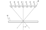
- the viewing angle indicates the spread width of the effective incident angle of light from an arbitrary position on the light irradiation surface LS, as shown in FIG. 6, and is the angle ⁇ in FIG.
- 30 is a light source part
- 31 is LED.
- FIG. 7A is a schematic diagram illustrating an outline of a configuration in an example of a conventional light irradiation apparatus using LEDs.
- a distance between the light source unit 30 in which the plurality of LEDs 31 are arranged on the same plane and the irradiation target W (actually, the light source unit 30 and the irradiation target). It is described that the distance between the masks 45 arranged between the objects W, the working distance (WD) is increased.
- the aperture array 40 is provided at a position close to the light source unit 30 as shown in FIG. 7B. As a result, the opening angle ⁇ of the light emitted from each LED 31 is reduced, and the spatial resolution of the light processing on the irradiated object W can be increased.
- FIG. 8 is a schematic diagram showing an outline of a configuration in still another example of a conventional light irradiation apparatus using LEDs. That is, it is described that the light source unit 30 is configured by arranging a plurality of segment light sources 30a each including a plurality of LEDs 31 and a light guide unit 35 arranged on the same substrate 32 in the surface direction of the substrate 32. ing. Thereby, it is supposed that the light emitted from each LED 31 is reflected by the inner surface of the light guide portion 35 and mixed so that the illuminance on the light irradiation surface LS can be made uniform.
- the number of LEDs 31 in each segment light source 30a is limited due to a structural reason for reflecting the light of each LED 31 a plurality of times. Accordingly, in order to avoid a decrease in illuminance on the light irradiation surface LS, a large number of segment light sources 30a are required. Furthermore, when there is illuminance variation for each segment light source 30a, it is necessary to provide a feedback control unit for each segment light source 30a, and it is difficult to make the illuminance uniform on the light irradiation surface LS (very complicated). ).
- the opening angle of the light emitted from the LED 31 is stored in the light guide 35. For this reason, the viewing angle on the light irradiation surface LS cannot be narrowed. Moreover, since the light emitted from the opening of the light guide part 35 is likely to spread before reaching the light irradiation surface LS, the illuminance on the light irradiation surface LS decreases. In order to prevent a decrease in illuminance on the light irradiation surface LS, as shown by a two-dot chain line in FIG. 8, it is considered that the distance from the opening end of the light guide 35 to the object to be processed W is reduced from WD1 to WD2. However, in such a case, it becomes a restriction on the device design, which is not preferable.
- the present invention has been made based on the above circumstances, and in a light irradiation apparatus including a plurality of LEDs, the viewing angle on the light irradiation surface can be reduced, and the illuminance on the light irradiation surface can be reduced. It aims at providing a highly uniform light irradiation apparatus.
- the light irradiation device of the present invention has a plurality of LEDs each having an optical axis extending in the z direction on the same plane extending in the x direction and the y direction when three directions orthogonal to each other are defined as an x direction, a y direction, and a z direction.
- a light irradiation apparatus comprising: a light source unit that is arranged side by side in the x direction and the y direction; and a reflection unit that reflects light from the light source unit.
- the reflection part has a form that spreads outward with respect to the reference axis as it goes forward in the light emitting direction, and the end position of the reflection part located on the light source part side and the light of the reflection part
- the inclination angle ( ⁇ 1 ) of the first imaginary line connecting the position of the emission side opening edge with respect to the z direction is 0 ° ⁇ 1 ⁇ 60 °, and the light emission of each LED on the reference axis
- the inclination angle ( ⁇ 2 ) with respect to the reference axis of the second imaginary line connecting the same z-direction level position as the plane on which the surface is located and the position of the light emitting side opening edge of the reflecting portion is 60 ° or less.
- the said light source part consists of several types from which a center light emission wavelength differs. Furthermore, in the light irradiation apparatus of this invention, it is preferable that the said reflection part has a light-diffusion reflective surface.
- the width of the LED arrangement region is sufficiently small with respect to the opening width of the reflection portion, and the light source portion is configured to have a plurality of LEDs densely arranged.
- the reflecting portion has a specific form, the emission angle of the light directly emitted from the LED through the opening of the reflecting portion and the emission angle of the reflected light reflected and emitted by the reflecting portion. Is regulated. For this reason, according to the light irradiation apparatus of the present invention, the viewing angle on the light irradiation surface can be suppressed to a small level, and the light mixing from each LED is increased, so that the illuminance uniformity on the light irradiation surface is improved. Can be high.
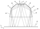
- FIG. 1A It is a perspective view which shows the outline of a structure in an example of the light irradiation apparatus of this invention. It is sectional drawing by the plane extended in the x direction and z direction in the light irradiation apparatus shown to FIG. 1A. It is a top view which shows the outline of a structure in an example of a light source part. It is sectional drawing by the plane extended in the x direction and the z direction which shows the outline of a structure of the reflection part in the light irradiation apparatus shown to FIG. 1A. It is a figure which shows schematically the structure in an example of the contact exposure apparatus to which the light irradiation apparatus of this invention was applied.
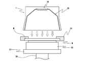
- FIG. 1 It is a figure which shows the state at the time of the exposure process in the contact exposure apparatus shown in FIG. It is a schematic diagram which shows the viewing angle in a light irradiation surface. It is a schematic diagram which shows the outline of a structure in an example of the conventional light irradiation apparatus using LED. It is a schematic diagram which shows the outline of the structure in the other example of the conventional light irradiation apparatus using LED. It is a schematic diagram which shows the outline of the structure in the further another example of the conventional light irradiation apparatus using LED.
- FIG. 1A is a perspective view showing an outline of a configuration in an example of a light irradiation apparatus of the present invention.
- 1B is a cross-sectional view taken along a plane extending in the x direction and the z direction in the light irradiation apparatus shown in FIG. 1A.
- FIG. 2 is a plan view illustrating the outline of the configuration of an example of the light source unit.
- the light irradiation device includes a light source unit 10 in which a plurality of LEDs 12 are arranged on the same plane, and a reflection unit 20 that reflects light from the light source unit 10.
- the light source unit 10 has a substrate 11 that is long in one direction (vertical direction in FIG. 2; hereinafter, this direction is referred to as “y direction”).
- y direction On the substrate 11, for example, a plurality of LED chips 12 are formed.
- the substrate 11 is arranged side by side in the y direction (longitudinal direction) and in a direction orthogonal to the y direction (left and right direction in FIG.
- the LEDs 12 adjacent to each other in the y direction are arranged so as to be shifted from each other in the x direction, so that the plurality of LEDs 12 are arranged in a staggered manner on the entire substrate 11.
- Each LED 12 is arranged in a posture in which the optical axis extends in a direction perpendicular to each of the x direction and the y direction (a direction perpendicular to the paper surface in FIG. 2; hereinafter, this direction is referred to as a “z direction”).
- the area indicated by the broken line is the LED arrangement area 15, and O indicates the center position thereof.
- the LED 12 may have the same central emission wavelength or different from each other, but it is preferable to use a plurality of types having different central emission wavelengths.
- the process with respect to a to-be-irradiated object can be performed with the light of several wavelengths instead of the light of a single wavelength.
- the vicinity of the surface can be cured with short-wavelength light, and the deep portion can be cured with long-wavelength light.
- high-resolution resist curing is possible.
- the reflection part 20 is comprised, for example by the cylindrical hollow body, and contains the axis
- the reflecting portion 20 has a symmetric structure with respect to a virtual plane including the reference axis C and extending in the y direction and the z direction.
- the reflection part 20 has a form which spreads outward with respect to the reference axis C as it goes forward in the light emission direction in the xz section or the yz section including the reference axis C, and the relationship (a) shown below To (c).
- (A) The inclination angle ( ⁇ 1 ) with respect to the z direction of the first imaginary line connecting the end position on the light source section side of the reflecting section 20 and the position of the light emitting side opening edge of the reflecting section 20 is 0 ° ⁇ 1 ⁇ 60 °.
- (B) The same z-direction level position (hereinafter referred to as “reference point”) as the plane on which the light emitting surface of each LED is located on the reference axis C, and the position of the light emitting side opening edge of the reflecting portion 20.
- the inclination angle ( ⁇ 2 ) of the second imaginary line connecting the two with respect to the reference axis C is 60 ° or less.
- (C) The ratio (Wa / Wb) between the width (Wa) of the LED arrangement region 15 in the light source unit 10 and the opening width (Wb) of the reflection unit 20 is 0.5 or less.
- the reflecting portion 20 in this example includes a pair of first mirror elements 21 that face each other in the x direction and a pair of second mirror elements 25 that face each other in the y direction.
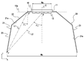
- the first mirror element 21 is continuous with a flat plate-like first inclined surface portion 22 extending at an inclination with respect to the z direction and a lower end of the first inclined surface portion 22 in the xz cross section including the reference axis C. And a flat plate-like second inclined surface portion 23 extending inclined with respect to the z direction.
- the inclination angles of the first inclined surface portion 22 and the second inclined surface portion 23 with respect to the z direction are set to different sizes in a state satisfying the above relationships (a) to (c).
- the inclination angle ⁇ 1 with respect to the z direction of the first virtual line L1 connecting the upper end position ⁇ of the first inclined surface portion 22 and the lower end position ⁇ of the second inclined surface portion 23 in the first mirror element 21 is 0 ° ⁇ 1 ⁇ 60 °.
- the inclination angle ⁇ 2 of the second virtual line L2 connecting the reference point ⁇ and the lower end position ⁇ of the second inclined surface portion 23 with respect to the reference axis C (z direction) is set to 60 ° or less.
- Wa of the LED arrangement region 15 in the light source unit 10 to the opening width Wb in the x direction of the reflection unit 20 is 0.5 or less.
- the magnitudes of the inclination angle ⁇ 1 and the inclination angle ⁇ 2 are such that the viewing angle on the light irradiation surface LS is 40 ° or less, more preferably 30 ° or less, within the range satisfying the relationships (a) to (c). It is preferable to set so as to be.
- the inner surface 21 a of the first mirror element 21, that is, the inner surface of the first inclined surface portion 22 and the inner surface of the second inclined surface portion 23 constitute a reflecting surface that reflects a part of light from the LED 12 (light with a large radiation angle).
- the inner surface of the first inclined surface portion 22 and the inner surface of the second inclined surface portion 23 are preferably diffuse reflection surfaces. Since the inner surface 21a of the first mirror element 21 is a diffuse reflection surface, even when the irradiation distance (work distance WD) is small, the uniformity of illuminance on the light irradiation surface LS can be improved. It becomes easy to maintain high illuminance.
- the diffuse reflection surface can be formed, for example, by providing a diffuser or by performing, for example, dimple processing on the inner surface 21a of the first mirror element 21.
- the second mirror element 25 is constituted by, for example, a planar mirror extending inclined with respect to the z direction. Similarly, the inner surface of the second mirror element 25 is preferably a diffuse reflection surface.
- the width Wa of the LED arrangement region 15 in the light source unit 10 is sufficiently smaller than the opening width Wb of the reflection unit 20 in the xz cross section including the reference axis C.
- the reflecting part 20 since the reflecting part 20 has a specific form, the reflected light emitted from the LED 12 through the opening of the reflecting part 20 and the reflection angle emitted by the reflecting part 20 is directly emitted.
- the emission angle is regulated. That is, the light directly emitted from the light source unit 10 to the light irradiation surface LS is largely restricted to a part of light having a small emission angle.
- the light from each LED 12 is superimposed on the light irradiation surface LS to compensate each other. Will fit.
- the uniformity of illuminance on the light irradiation surface LS can be increased, and light irradiation with high stability can be performed.
- the reflecting portion is not limited to the configuration according to the above-described embodiment as long as it satisfies the relationships (a) to (c).
- the first mirror element constituting the reflecting portion does not have to have a plurality of inclined surface portions having different inclination angles with respect to the z direction.
- the first mirror element may have a shape curved in an arc shape.
- the reflection part does not need to be arranged in a state where the end part on the light source part side is located at the same z-direction level position as the light source part, and may be arranged forward of the light emission direction from the light source part. Good.
- the light irradiation apparatus as described above can be suitably used as a light source for, for example, an exposure apparatus used for exposure of a semiconductor substrate or a liquid crystal substrate by photolithography and other fine processing.
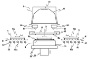
- FIG. 4 is a diagram schematically showing a configuration of an example of a contact exposure apparatus to which the light irradiation apparatus of the present invention is applied.
- This contact exposure apparatus (hereinafter simply referred to as “exposure apparatus”) uses, for example, ultraviolet light as exposure light, and the exposure light passes through a photomask M to an object to be irradiated (hereinafter also referred to as “work”) W. Irradiation.
- the exposure apparatus includes, for example, a light irradiation unit 1 configured by the light irradiation apparatus illustrated in FIG. 1, a mask stage 50 that holds a photomask M on which a pattern to be exposed (transferred) to the work W is formed, and a work W.
- the workpiece W include substrate materials such as a printed board, a semiconductor substrate, and a liquid crystal substrate.
- the mask stage 50 includes mask holding means (not shown) that holds the peripheral edge portion of the upper surface of the photomask M by, for example, vacuum suction.
- the mask stage 50 may be configured to be movable in the XY ⁇ direction within a horizontal plane along the work placement surface of the work stage 55 by an appropriate stage drive mechanism (not shown).
- the work stage 55 is provided with a work holding means (not shown) for holding the work W placed on a flat work placing surface by, for example, vacuum suction.
- the work stage 55 is configured to be movable in an XYZ ⁇ direction (a surface direction along the work placement surface, a height direction, and a rotation direction about an axis perpendicular to the work placement surface) by a stage driving mechanism 56.
- the stage drive mechanism 56 includes, for example, an XY ⁇ stage 57 and an elevating stage (Z stage) 58.
- the alignment mechanism 60 includes a mask / alignment mark Ma formed on the photomask M, an alignment mark detection unit 61 that simultaneously detects the workpiece / alignment mark Wa formed on the workpiece W, and the alignment mark detection unit 61 as a light irradiation unit. 1 and a moving mechanism (not shown) that is inserted into or retracted from the position between the mask stage 50 and the mask stage 50.
- the alignment mark detection means 61 for example, an imaging device such as a CCD camera can be used.
- the workpiece conveyance mechanism includes a carry-in conveyance mechanism 65a that carries in the workpiece W before the exposure processing, and a carry-out conveyance mechanism 65b that carries out the workpiece W after the exposure processing.
- the carry-in side transport mechanism 65a and the carry-out side transport mechanism 65b are configured by, for example, roller conveyors.
- the carry-in side transport mechanism 65a in this example includes a plurality of conveyor shafts 66 extending in parallel to each other in a horizontal plane and perpendicular to the transport direction of the workpiece W, and each of the conveyor shafts 66 includes a plurality of rollers 67. It is configured to be rotatable.
- the carry-out side transport mechanism 65b has the same configuration.
- the workpiece transfer mechanism includes a transfer-side transfer mechanism 70a that transfers the workpiece W on the conveyor in the transfer-side transfer mechanism 65a onto the workpiece stage 55, and the workpiece W after the exposure processing from the workpiece stage 55 to the discharge side.
- An unloading side transfer mechanism 70b for transferring on the conveyor of the transport mechanism 65b is provided.
- the carry-in transfer mechanism 70 a and the carry-out transfer mechanism 70 b include, for example, a transfer arm 71 that holds the workpiece W by suction, and the transfer arm 71 is positioned between the work stage 55 and the mask stage 50. It is provided so that it can be inserted and retracted.
- the exposure process for the workpiece W is performed as follows. First, the work W carried into the apparatus by the carry-in transport mechanism 65a is transferred onto the work stage 55 by the carry-in transfer mechanism 70a. That is, after the work W on the conveyor is sucked and held by the transfer arm 71, the transfer arm 71 is moved in the horizontal direction while holding the work W and is positioned above the work stage 55. In this state, the work W is placed on the work stage 55 by releasing the suction and holding of the work W by the transfer arm 71. Thereafter, the transfer arm 71 is retracted to a predetermined position. The work W placed on the work stage 55 is sucked and held, for example, by a work holding means provided on the work stage 55.
- the alignment mark detection means 61 detects the mask alignment mark Ma on the photomask M and the work alignment mark Wa on the work W. Thereby, the position information of the work W on the work stage 55 and the position information of the photomask M held on the mask stage 50 are acquired, and the work W and the photomask M on the work stage are acquired based on the position information. Is aligned. That is, the control unit sets alignment amounts in the X direction, the Y direction, and the ⁇ direction based on the detected position information, and, for example, the XY ⁇ stage 57 that configures the stage drive mechanism 56 is set according to the alignment amount. Move. Thereby, alignment with the workpiece
- the alignment of the workpiece W and the photomask M may be performed by moving one of the workpiece stage 55 and the mask stage 50 relative to the other, and accordingly, the alignment amount in which the mask stage 50 is set. May be driven according to
- the work stage 55 is raised by the elevating stage 58 constituting the stage driving mechanism 56 so that the surface of the work W adheres to the mask M as shown in FIG. State.
- exposure light for example, UV light, indicated by a white arrow in FIG. 5
- the light irradiation unit 1 is applied to the workpiece W on the workpiece stage 55 via the photomask M held on the mask stage 50. Irradiating the surface, the pattern formed on the photomask M is exposed (transferred) to the workpiece W.
- the workpiece stage 55 is lowered by the elevating stage 58 constituting the stage driving mechanism 56, and the workpiece W on the workpiece stage 55 is transferred to the conveyor in the unloading side transfer mechanism 65b by the unloading side transfer mechanism 70b. Reprinted on top. Then, the work W is carried out of the apparatus by the carry-out side conveyance mechanism 65b.
- the exposure processing of the workpiece W is processed. It can be performed with high resolution without causing unevenness.
- the light source unit is arranged so that about 2000 LEDs are arranged in the x direction and the y direction in an LED arrangement region in which the dimension (Wa) in the x direction is 20 mm and the dimension in the y direction is 360 mm. It is configured. Each LED has a light emission angle of 60 °.
- the reflecting portion includes a first imaginary line (L1) connecting the upper end position ( ⁇ ) of the first inclined surface portion and the lower end position ( ⁇ ) of the second inclined surface portion in the first mirror element.
- the inclination angle ⁇ 1 with respect to the z direction is 30.2 °.
- the inclination angle ⁇ 2 of the second imaginary line (L2) connecting the two with respect to the z direction is 41.2 °.
- the second mirror element has a planar shape, and the tilt angle with respect to the z direction is 26.7 ° in the yz section including the reference axis.
- a hammer pattern or a stucco pattern is provided on the inner surface of each of the first mirror element and the second mirror element to form a diffuse reflection surface.
- the light source unit is configured such that about 2000 LEDs are arranged in the x direction and the y direction in an LED arrangement region where the dimension (Wa) in the x direction is 287 mm and the dimension in the y direction is 360 mm. Each LED has a light emission angle of 60 °.
- the reflecting portion is composed of a pair of planar first mirror elements and a pair of planar second mirror elements that extend with an inclination angle of a certain size with respect to the z direction.
- the upper end of the reflecting portion is located at the same z-direction level position as the LED arrangement surface, and in the xz section including the reference axis, the inclination angle ⁇ 1 of the first mirror element with respect to the z-direction is 18.9 °.
- the inclination angle ⁇ 2 of the second imaginary line connecting ⁇ ) with respect to the z direction is 41.2 °.
- a hammer pattern or a stucco pattern is provided on the inner surface of each of the first mirror element and the second mirror element to form a diffuse reflection surface.
- the inclination angle ⁇ 2 of the second imaginary line connecting the position ( ⁇ ) of the opening edge with respect to the z direction is 16.3 °.
- the dimension in the z direction is 180 mm
- the reference point ( ⁇ ) and the lower end position ( ⁇ ) of the first mirror element are
- the inclination angle ⁇ 2 of the second virtual line to be connected with respect to the z direction is 66.2 °.
- a light irradiation device having the same specifications as in Example 2 was manufactured except that a light source unit and a reflection unit having the following structure were used.
- the light source unit is configured such that about 2000 LEDs are arranged in the x direction and the y direction in an LED arrangement region in which the dimension (Wa) in the x direction is 459 mm and the dimension in the y direction is 360 mm.
- the reflection portion has an inclination angle ⁇ 1 with respect to the z direction of the first mirror element of 6.4 °, and a ratio (Wa / Wb) between the width (Wa) of the LED arrangement region and the opening width (Wb) of the reflection portion.
- the dimension of the z direction is 328 mm
- the opening width (Wb) in the x direction is 574 mm
- the second imaginary line connecting the reference point ( ⁇ ) and the position ( ⁇ ) of the light emitting side opening edge of the reflecting portion is 41.2 °.
- Example 1 For each of the light irradiation devices according to Example 1, Example 2, and Comparative Examples 1 to 3, the viewing angle on the light irradiation surface disposed at a position 374 mm away from the light emitting side opening end surface of the reflecting portion in the z direction. And the illuminance uniformity on the light irradiation surface was examined. The results are shown in Table 1 below. [Viewing angle] The effective viewing angle was obtained from the half width at half maximum of the illuminance distribution on the light irradiation surface, and this value was used as the viewing angle on the light irradiation surface.
- the viewing angle on the light irradiation surface can be reduced, and high uniformity of illuminance can be obtained on the light irradiation surface.
Landscapes
- Engineering & Computer Science (AREA)
- General Engineering & Computer Science (AREA)
- Exposure And Positioning Against Photoresist Photosensitive Materials (AREA)
Abstract
本発明は、光照射面での視角が小さく抑制され、光照射面において高い照度の均一性の得られる光照射装置を提供することを目的とする。 この光照射装置は、複数のLEDがx方向およびy方向に並んで配置された光源部と、LED配置領域の中心位置を通るz方向に延びる基準軸を含むxz断面またはyz断面において、光射出方向前方に向かうに従って基準軸に対して外方に広がる形態を有する反射部とを備えており、反射部が以下の条件を満足する構造とされている。光源部側の端部位置と光出射側開口端縁位置とを結ぶ第一仮想線のz方向に対する傾斜角度θ1 、基準軸上における各々のLEDの光出射面と同じz方向レベル位置と光出射側開口端縁位置とを結ぶ第二仮想線の基準軸に対する傾斜角度θ2 およびLED配置領域の幅の、反射部の開口幅に対する比率が、特定の大きさとされている。
Description
本発明は、複数のLEDを用いた光照射装置に関する。
半導体や液晶の露光、その他の微細加工の分野においては、フォトリソグラフィの光源として、例えばメタルハライドランプ等の紫外線ランプを用いた露光技術が利用されている。
しかしながら、メタルハライドランプ等の紫外線ランプは、消灯後すぐに再点灯することが難しく、エネルギーロスが大きい、というデメリットがある。また、紫外線とともに発生する熱線により、被照射対象物が不所望に加熱されてしまう、という問題があった。
近年では、紫外線ランプの代替光源としてLEDを用いた光照射装置を備えた露光装置の開発が活発に行われている。
しかしながら、メタルハライドランプ等の紫外線ランプは、消灯後すぐに再点灯することが難しく、エネルギーロスが大きい、というデメリットがある。また、紫外線とともに発生する熱線により、被照射対象物が不所望に加熱されてしまう、という問題があった。
近年では、紫外線ランプの代替光源としてLEDを用いた光照射装置を備えた露光装置の開発が活発に行われている。
而して、紫外線ランプに代えてLEDを光源として用いる場合には、主に、以下に示す2つの問題がある。
第一に、紫外線ランプは、電極間に形成されるアークの輝点から高い放射量の光を得ることが可能であるが、LEDは一チップあたりの光放射量は小さい。このため、露光装置用の光源として用いるためには、多数のLEDを搭載した光源部が必要となる。しかしながら、各LEDの光放射出力には、LEDの個体差や、熱分布の影響などに起因するバラツキが生じやすい。さらには、一部のLEDが不点灯となることも考えられる。このような理由から、多数のLEDを搭載した光源部を備えた光照射装置においては、光照射面での照度を均一にすることが難しい。
第一に、紫外線ランプは、電極間に形成されるアークの輝点から高い放射量の光を得ることが可能であるが、LEDは一チップあたりの光放射量は小さい。このため、露光装置用の光源として用いるためには、多数のLEDを搭載した光源部が必要となる。しかしながら、各LEDの光放射出力には、LEDの個体差や、熱分布の影響などに起因するバラツキが生じやすい。さらには、一部のLEDが不点灯となることも考えられる。このような理由から、多数のLEDを搭載した光源部を備えた光照射装置においては、光照射面での照度を均一にすることが難しい。
また、第二に、同一平面上に複数のLEDが配置された光源部においては、各LEDからの光が光照射面へ出射される際、光照射面に対する視角が広がりやすい、という問題がある。視角が大きくなると、被照射対象物に対する光処理の空間分解能が低下して処理精度が悪化する要因となる。ここでいう「視角」とは、図6に示されるように、光照射面LSにおける任意の位置からの光の有効入射角の拡がり幅を示すもので、図6における角度αのことである。図6において、30は光源部、31はLEDである。
上記2つの課題に対して、例えば特許文献1には、以下のような対策が講じられることが記載されている。図7Aは、LEDを用いた従来の光照射装置の一例における構成の概略を示す模式図である。
まず、上記第一の課題に対しては、複数のLED31が同一平面上に配置されてなる光源部30と、被照射対象物Wとの間の距離(実際には光源部30と被照射対象物Wの間に配置されるマスク45との間の距離、ワーキングディスタンス)WDを大きくすることが記載されている。これにより、各LED31から放射される光が混ざり合うことで、個々のLED31の光放射出力のバラツキが緩和(補償)されて光照射面LSにおける照度の均一性を向上させることができるとされている。
また、上記第二の課題に対しては、図7Bに示すように、アパーチャーアレイ40を光源部30に近接した位置に設けることが記載されている。これにより、各LED31から放射される光の開き角θが小さくなり、被照射対象物Wに対する光処理の空間分解能を上げることができるとされている。
まず、上記第一の課題に対しては、複数のLED31が同一平面上に配置されてなる光源部30と、被照射対象物Wとの間の距離(実際には光源部30と被照射対象物Wの間に配置されるマスク45との間の距離、ワーキングディスタンス)WDを大きくすることが記載されている。これにより、各LED31から放射される光が混ざり合うことで、個々のLED31の光放射出力のバラツキが緩和(補償)されて光照射面LSにおける照度の均一性を向上させることができるとされている。
また、上記第二の課題に対しては、図7Bに示すように、アパーチャーアレイ40を光源部30に近接した位置に設けることが記載されている。これにより、各LED31から放射される光の開き角θが小さくなり、被照射対象物Wに対する光処理の空間分解能を上げることができるとされている。
一方、例えば特許文献2には、上記2つの課題に対して、以下のような対策が講じられることが記載されている。図8は、LEDを用いた従来の光照射装置のさらに他の例における構成の概略を示す模式図である。
すなわち、各々、同一の基板32上に配置された複数のLED31と導光部35とよりなる複数のセグメント光源30aを基板32の面方向に並べて配置して光源部30を構成することが記載されている。これにより、各々のLED31から放射される光が導光部35の内面によって反射されることで混合されて光照射面LSにおける照度を均一化することができるとされている。
すなわち、各々、同一の基板32上に配置された複数のLED31と導光部35とよりなる複数のセグメント光源30aを基板32の面方向に並べて配置して光源部30を構成することが記載されている。これにより、各々のLED31から放射される光が導光部35の内面によって反射されることで混合されて光照射面LSにおける照度を均一化することができるとされている。
しかしながら、特許文献1に記載の光照射装置においては、アパーチャーアレイ40等の光学部品を用いて開き角θを狭めると、各LED31の光は混ざり合いにくくなる(混光性が低い)。このため、光照射面LSでの視角を狭めることはできるが、光照射面LSにおける照度の均一性を悪化させてしまう。この場合、照度の均一性を確保するためには、ワーキングディスタンスWDを非常に大きくする必要があり、装置の大型化を招くと共に、光の利用効率も低くなる。
一方、特許文献2に記載の光照射装置においては、各LED31の光を複数回反射させる構造上の理由から、各セグメント光源30aにおけるLED31の数が限定されてしまう。従って、光照射面LSにおける照度の低下を回避するためには、多数のセグメント光源30aが必要となる。
さらにまた、セグメント光源30a毎に照度のバラツキがある場合には、それぞれセグメント光源30a毎にフィードバック制御部を設ける必要があり、光照射面LSにおける照度の均一化を図ることが困難(非常に煩雑化)となってしまう。
さらにまた、特許文献2に記載の光照射装置においては、LED31から放射される光の開き角は導光部35内で保存される。このため、光照射面LSでの視角を狭めることはできない。また、導光部35の開口から出射された光は、光照射面LSに達するまでの間に、広がりやすいため、光照射面LSにおける照度が低下してしまう。光照射面LSにおける照度の低下を防ぐためには、図8において二点鎖線で示すように、導光部35の開口端から被処理対象物Wまでの距離をWD1からWD2に小さくすることが考えられるが、このような場合には、装置設計上の制約となってしまい、好ましくない。
さらにまた、セグメント光源30a毎に照度のバラツキがある場合には、それぞれセグメント光源30a毎にフィードバック制御部を設ける必要があり、光照射面LSにおける照度の均一化を図ることが困難(非常に煩雑化)となってしまう。
さらにまた、特許文献2に記載の光照射装置においては、LED31から放射される光の開き角は導光部35内で保存される。このため、光照射面LSでの視角を狭めることはできない。また、導光部35の開口から出射された光は、光照射面LSに達するまでの間に、広がりやすいため、光照射面LSにおける照度が低下してしまう。光照射面LSにおける照度の低下を防ぐためには、図8において二点鎖線で示すように、導光部35の開口端から被処理対象物Wまでの距離をWD1からWD2に小さくすることが考えられるが、このような場合には、装置設計上の制約となってしまい、好ましくない。
本発明は、以上のような事情に基づいてなされたものであって、複数のLEDを備えた光照射装置において、光照射面での視角を小さく抑制することができ、光照射面における照度の均一性の高い光照射装置を提供することを目的とする。
本発明の光照射装置は、互いに直交する3つの方向をx方向、y方向およびz方向としたとき、x方向およびy方向に延びる同一平面上において、各々光軸がz方向に延びる複数のLEDがx方向およびy方向に並んで配置されてなる光源部と、当該光源部からの光を反射する反射部とを備えた光照射装置において、
前記光源部におけるLED配置領域の中心位置を含むz方向に延びる軸を基準軸としたとき、当該基準軸を含むxz断面またはyz断面において、
前記反射部は、光出射方向前方に向かうに従って当該基準軸に対して外方に広がる形態を有しており、当該反射部における前記光源部側に位置される端部位置と当該反射部の光出射側開口端縁の位置とを結ぶ第一仮想線の、z方向に対する傾斜角度(θ1)が0°<θ1<60°とされ、かつ、当該基準軸上における各々のLEDの光出射面が位置される平面と同じz方向レベル位置と当該反射部の光出射側開口端縁の位置とを結ぶ第二仮想線の、当該基準軸に対する傾斜角度(θ2)が60°以下とされており、
前記LED配置領域の幅(Wa)と前記反射部の開口幅(Wb)との比率(Wa/Wb)が0.5以下とされていることを特徴とする。
前記光源部におけるLED配置領域の中心位置を含むz方向に延びる軸を基準軸としたとき、当該基準軸を含むxz断面またはyz断面において、
前記反射部は、光出射方向前方に向かうに従って当該基準軸に対して外方に広がる形態を有しており、当該反射部における前記光源部側に位置される端部位置と当該反射部の光出射側開口端縁の位置とを結ぶ第一仮想線の、z方向に対する傾斜角度(θ1)が0°<θ1<60°とされ、かつ、当該基準軸上における各々のLEDの光出射面が位置される平面と同じz方向レベル位置と当該反射部の光出射側開口端縁の位置とを結ぶ第二仮想線の、当該基準軸に対する傾斜角度(θ2)が60°以下とされており、
前記LED配置領域の幅(Wa)と前記反射部の開口幅(Wb)との比率(Wa/Wb)が0.5以下とされていることを特徴とする。
本発明の光照射装置においては、前記光源部を構成する複数のLEDは、中心発光波長が異なる複数種類のものよりなることが好ましい。
さらにまた、本発明の光照射装置においては、前記反射部は、光拡散性反射面を有することが好ましい。
さらにまた、本発明の光照射装置においては、前記反射部は、光拡散性反射面を有することが好ましい。
本発明の光照射装置においては、LED配置領域の幅が反射部の開口幅に対して十分に小さく、光源部は複数のLEDが密に配置された構成とされている。しかも、反射部が特定の形態を有するものであることにより、LEDから反射部の開口を介して直接的に出射される光の出射角および反射部によって反射されて出射される反射光の出射角が規制される。このため、本発明の光照射装置によれば、光照射面での視角を小さく抑制することができると共に、各LEDからの光の混光性が高くなって光照射面における照度の均一性を高くすることができる。
以下、本発明の実施の形態について詳細に説明する。
図1Aは、本発明の光照射装置の一例における構成の概略を示す斜視図である。図1Bは、図1Aに示す光照射装置におけるx方向およびz方向に延びる平面による断面図である。図2は、光源部の一例における構成の概略を示す平面図である。
この光照射装置は、複数のLED12が同一平面上に配置されてなる光源部10と、光源部10からの光を反射する反射部20とを備えている。
図1Aは、本発明の光照射装置の一例における構成の概略を示す斜視図である。図1Bは、図1Aに示す光照射装置におけるx方向およびz方向に延びる平面による断面図である。図2は、光源部の一例における構成の概略を示す平面図である。
この光照射装置は、複数のLED12が同一平面上に配置されてなる光源部10と、光源部10からの光を反射する反射部20とを備えている。
光源部10は、一方向(図2において上下方向。以下、この方向を「y方向」という。)に長尺な基板11を有し、この基板11上に、例えばチップ状の複数のLED12が、基板11のy方向(長手方向)およびy方向に直交する方向(図2において左右方向。以下、この方向を「x方向」という。)に並んで配置されている。この例においては、y方向に隣接するLED12が互いにx方向にずれるように配置されることにより、基板11全体において、複数のLED12が千鳥状に配置されている。各々のLED12は、光軸がx方向およびy方向の各々に直交する方向(図2において紙面に垂直な方向。以下、この方向を「z方向」という。)に延びる姿勢で配置されている。図2において破線で示す領域はLED配置領域15であって、Oはその中心位置を示す。
LED12は、中心発光波長が互いに同一のものであっても、互いに異なるものであってもよいが、中心発光波長が異なる複数種のものが用いられることが好ましい。これにより、被照射対象物に対する処理を単一波長の光ではなく、複数の波長の光で行うことができる。例えば、厚膜レジストの硬化処理であれば、短波長の光で表面近傍を硬化させると共に、長波長の光で深部を硬化させることができ、結果として高分解能のレジスト硬化が可能となる。
反射部20は、例えば筒状の中空体により構成されており、光源部10におけるLED配置領域15の中心位置Oを含むz方向に延びる軸(以下、「基準軸」という。)Cを含む、x方向およびz方向に延びる仮想平面Fに関して対称な構造(図1Bにおいて左右対称)を有する。図示はしていないが、反射部20は、基準軸Cを含む、y方向およびz方向に延びる仮想平面に関しても対称な構造を有する。
また、反射部20は、基準軸Cを含むxz断面またはyz断面において、光射出方向前方に向かうに従って基準軸Cに対して外方に広がる形態を有しており、以下に示す関係(a)~(c)を満足する構成とされている。
(a)反射部20における光源部側の端部位置と反射部20の光出射側開口端縁の位置とを結ぶ第一仮想線の、z方向に対する傾斜角度(θ1)が0°<θ1<60°であること。
(b)基準軸C上における各々のLEDの光出射面が位置される平面と同じz方向レベル位置(以下、「基準点」という。)と反射部20の光出射側開口端縁の位置とを結ぶ第二仮想線の、基準軸Cに対する傾斜角度(θ2)が60°以下であること。
(c)光源部10におけるLED配置領域15の幅(Wa)と反射部20の開口幅(Wb)との比率(Wa/Wb)が0.5以下であること。
また、反射部20は、基準軸Cを含むxz断面またはyz断面において、光射出方向前方に向かうに従って基準軸Cに対して外方に広がる形態を有しており、以下に示す関係(a)~(c)を満足する構成とされている。
(a)反射部20における光源部側の端部位置と反射部20の光出射側開口端縁の位置とを結ぶ第一仮想線の、z方向に対する傾斜角度(θ1)が0°<θ1<60°であること。
(b)基準軸C上における各々のLEDの光出射面が位置される平面と同じz方向レベル位置(以下、「基準点」という。)と反射部20の光出射側開口端縁の位置とを結ぶ第二仮想線の、基準軸Cに対する傾斜角度(θ2)が60°以下であること。
(c)光源部10におけるLED配置領域15の幅(Wa)と反射部20の開口幅(Wb)との比率(Wa/Wb)が0.5以下であること。
この例における反射部20は、x方向において互いに対向する一対の第一ミラー素子21と、y方向において互いに対向する一対の第二ミラー素子25とにより構成されている。
第一ミラー素子21は、図3に示すように、基準軸Cを含むxz断面において、z方向に対して傾斜して延びる平板状の第一傾斜面部22および第一傾斜面部22の下端に連続してz方向に対して傾斜して延びる平板状の第二傾斜面部23を有する。そして、第一傾斜面部22および第二傾斜面部23の各々のz方向に対する傾斜角度は、上記関係(a)~(c)を満足する状態で、互いに異なる大きさに設定されている。
すなわち、この例においては、第一ミラー素子21における第一傾斜面部22の上端位置βと第二傾斜面部23の下端位置γとを結ぶ第一仮想線L1の、z方向に対する傾斜角度θ1 が0°<θ1<60°とされている。また、基準点δと第二傾斜面部23の下端位置γとを結ぶ第二仮想線L2の、基準軸C(z方向)に対する傾斜角度θ2 が60°以下とされている。
さらに、光源部10におけるLED配置領域15の幅(図3においてはx方向寸法)Waと、反射部20のx方向における開口幅Wbとの比率(Wa/Wb)が0.5以下の大きさとされている。
傾斜角度θ1 および傾斜角度θ2 の大きさは、上記(a)~(c)の関係を満足する範囲内において、光照射面LSでの視角が40°以下、より好ましくは30°以下となるよう、設定されることが好ましい。
すなわち、この例においては、第一ミラー素子21における第一傾斜面部22の上端位置βと第二傾斜面部23の下端位置γとを結ぶ第一仮想線L1の、z方向に対する傾斜角度θ1 が0°<θ1<60°とされている。また、基準点δと第二傾斜面部23の下端位置γとを結ぶ第二仮想線L2の、基準軸C(z方向)に対する傾斜角度θ2 が60°以下とされている。
さらに、光源部10におけるLED配置領域15の幅(図3においてはx方向寸法)Waと、反射部20のx方向における開口幅Wbとの比率(Wa/Wb)が0.5以下の大きさとされている。
傾斜角度θ1 および傾斜角度θ2 の大きさは、上記(a)~(c)の関係を満足する範囲内において、光照射面LSでの視角が40°以下、より好ましくは30°以下となるよう、設定されることが好ましい。
第一ミラー素子21の内面21a、すなわち第一傾斜面部22の内面および第二傾斜面部23の内面は、LED12からの光の一部(放射角の大きい光)を反射する反射面を構成するが、第一傾斜面部22の内面および第二傾斜面部23の内面は、拡散反射面とされていることが好ましい。第一ミラー素子21の内面21aが拡散反射面とされていることにより、照射距離(ワークディスタンスWD)が小さい場合であっても、光照射面LSにおける照度の均一性を向上させることができ、高い照度を維持しやすくなる。
拡散反射面は、例えば、拡散体を設けることや、第一ミラー素子21の内面21aに例えばデインプル加工を施すことなどにより形成することができる。
拡散反射面は、例えば、拡散体を設けることや、第一ミラー素子21の内面21aに例えばデインプル加工を施すことなどにより形成することができる。
第二ミラー素子25は、例えば、z方向に対して傾斜して延びる平面状ミラーにより構成されている。第二ミラー素子25の内面についても同様に、拡散反射面とされていることが好ましい。
而して、上記の光照射装置においては、基準軸Cを含むxz断面において、光源部10におけるLED配置領域15の幅Waが反射部20の開口幅Wbに対して十分に小さく、光源部10は複数のLED12が密に配置された構成とされている。しかも、反射部20が特定の形態を有するものであることにより、LED12から反射部20の開口を介して直接的に出射される光の出射角および反射部20によって反射されて出射される反射光の出射角が規制される。すなわち、光源部10から光照射面LSへ直接的に出射される光は、放射角が小さい一部の光に大きく規制されることになる。一方、LED12からの放射角が大きな光は、反射部20で反射されて間接的に光照射面LSに向かって出射される。然るに、第一ミラー素子21の内面21aによって、x方向における基準軸C方向に向かって反射されるため、反射光の出射角は小さく抑制されることとなる。
従って、上記の光照射装置によれば、後述する実施例の結果に示されるように、光照射面LSでの視角を小さく抑制することができる。また、上記の光照射装置によれば、各LED12からの光の混光性が高くなる。このため、LEDの光放射出力のバラツキや、任意のLEDの経時的な光量減少などといった不具合が生じた場合であっても、光照射面LSにおいて各LED12からの光が重畳されて互いに補償し合うこととなる。その結果、上記の光照射装置によれば、光照射面LSにおける照度の均一性を高くすることができると共に、安定性の高い光照射を行うことができる。
従って、上記の光照射装置によれば、後述する実施例の結果に示されるように、光照射面LSでの視角を小さく抑制することができる。また、上記の光照射装置によれば、各LED12からの光の混光性が高くなる。このため、LEDの光放射出力のバラツキや、任意のLEDの経時的な光量減少などといった不具合が生じた場合であっても、光照射面LSにおいて各LED12からの光が重畳されて互いに補償し合うこととなる。その結果、上記の光照射装置によれば、光照射面LSにおける照度の均一性を高くすることができると共に、安定性の高い光照射を行うことができる。
以上、本発明の実施形態について説明したが、本発明は上記の実施形態に限定されるものではなく、種々の変更を加えることができる。
例えば、反射部は、上記(a)~(c)の関係を満足するものであれば、上記実施の形態に係る構成のものに限定されない。例えば、反射部を構成する第一ミラー素子はz方向に対する傾斜角度が互いに異なる複数の傾斜面部を有する構成とされている必要はない。また、第一ミラー素子は、弧状に湾曲した形態を有するものであってもよい。
さらにまた、反射部は、光源部側の端部が光源部と同じz方向レベル位置に位置された状態で配置されている必要はなく、光源部より光出射方向前方側に配置されていてもよい。
例えば、反射部は、上記(a)~(c)の関係を満足するものであれば、上記実施の形態に係る構成のものに限定されない。例えば、反射部を構成する第一ミラー素子はz方向に対する傾斜角度が互いに異なる複数の傾斜面部を有する構成とされている必要はない。また、第一ミラー素子は、弧状に湾曲した形態を有するものであってもよい。
さらにまた、反射部は、光源部側の端部が光源部と同じz方向レベル位置に位置された状態で配置されている必要はなく、光源部より光出射方向前方側に配置されていてもよい。
以上のような光照射装置は、例えばフォトリソグラフィによる半導体基板や液晶基板の露光およびその他の微細加工に用いられる露光装置などの光源として好適に用いることができる。
図4は、本発明の光照射装置が適用されたコンタクト露光装置の一例における構成を概略的に示す図である。
このコンタクト露光装置(以下、単に「露光装置」という。)は、例えば紫外光を露光光とし、露光光をフォトマスクMを介して被照射対象物(以下、「ワーク」ともいう。)Wに照射するものである。この露光装置は、例えば図1に示す光照射装置により構成された光照射部1と、ワークWに露光(転写)するパターンが形成されたフォトマスクMを保持するマスクステージ50と、ワークWを保持するワークステージ55と、ワークステージ55に保持されたワークWとフォトマスクMとの位置合わせを行うためのアライメント機構60と、ワークWを搬送するワーク搬送機構と、装置の各動作を制御する制御部(不図示)とを備えている。ワークWとしては、例えばプリント基板、半導体基板、液晶基板といった基板材料を例示することができる。
このコンタクト露光装置(以下、単に「露光装置」という。)は、例えば紫外光を露光光とし、露光光をフォトマスクMを介して被照射対象物(以下、「ワーク」ともいう。)Wに照射するものである。この露光装置は、例えば図1に示す光照射装置により構成された光照射部1と、ワークWに露光(転写)するパターンが形成されたフォトマスクMを保持するマスクステージ50と、ワークWを保持するワークステージ55と、ワークステージ55に保持されたワークWとフォトマスクMとの位置合わせを行うためのアライメント機構60と、ワークWを搬送するワーク搬送機構と、装置の各動作を制御する制御部(不図示)とを備えている。ワークWとしては、例えばプリント基板、半導体基板、液晶基板といった基板材料を例示することができる。
マスクステージ50は、フォトマスクMの上面における周縁部を例えば真空吸着により保持するマスク保持手段(図示せず)を備えている。
なお、マスクステージ50は、適宜のステージ駆動機構(図示せず)によって、ワークステージ55のワーク載置面に沿った水平面内でXYθ方向に移動可能に構成されていてもよい。
なお、マスクステージ50は、適宜のステージ駆動機構(図示せず)によって、ワークステージ55のワーク載置面に沿った水平面内でXYθ方向に移動可能に構成されていてもよい。
ワークステージ55には、平坦なワーク載置面上に載置されたワークWを例えば真空吸着により保持するワーク保持手段(不図示)が設けられている。
ワークステージ55は、ステージ駆動機構56によって、XYZθ方向(ワーク載置面に沿った面方向、高さ方向およびワーク載置面に垂直な軸を中心とした回転方向)に移動可能に構成されている。ステージ駆動機構56は、例えばXYθステージ57と、昇降ステージ(Zステージ)58とを備えている。
ワークステージ55は、ステージ駆動機構56によって、XYZθ方向(ワーク載置面に沿った面方向、高さ方向およびワーク載置面に垂直な軸を中心とした回転方向)に移動可能に構成されている。ステージ駆動機構56は、例えばXYθステージ57と、昇降ステージ(Zステージ)58とを備えている。
アライメント機構60は、フォトマスクMに形成されたマスク・アライメントマークMaと、ワークWに形成されたワーク・アライメントマークWaを同時に検出するアライメントマーク検出手段61と、アライメントマーク検出手段61を光照射部1とマスクステージ50との間の位置に挿入または当該位置から退避させる移動機構(図示せず)とを備えている。アライメントマーク検出手段61としては、例えばCCDカメラのような撮像装置を用いることができる。
ワーク搬送機構は、露光処理前のワークWを搬入する搬入側搬送機構65aと、露光処理が終わったワークWを搬出する搬出側搬送機構65bとを備えている。搬入側搬送機構65aおよび搬出側搬送機構65bは、例えばローラコンベアにより構成されている。この例における搬入側搬送機構65aは、水平面内において互いに平行にワークWの搬送方向と直交する方向に延びる複数のコンベア軸66を備えており、各々のコンベア軸66に、複数個のローラ67が回転自在に設けられて構成されている。搬出側搬送機構65bについても同様の構成とされている。
また、ワーク搬送機構は、搬入側搬送機構65aにおけるコンベア上のワークWをワークステージ55上に移載する搬入側移載機構70a、および、露光処理後のワークWをワークステージ55上から搬出側搬送機構65bのコンベア上に移載する搬出側移載機構70bを備えている。搬入側移載機構70aおよび搬出側移載機構70bは、例えばワークWを吸着保持する移載アーム71を備えており、当該移載アーム71は、ワークステージ55とマスクステージ50との間の位置に挿入退避可能に設けられている。
また、ワーク搬送機構は、搬入側搬送機構65aにおけるコンベア上のワークWをワークステージ55上に移載する搬入側移載機構70a、および、露光処理後のワークWをワークステージ55上から搬出側搬送機構65bのコンベア上に移載する搬出側移載機構70bを備えている。搬入側移載機構70aおよび搬出側移載機構70bは、例えばワークWを吸着保持する移載アーム71を備えており、当該移載アーム71は、ワークステージ55とマスクステージ50との間の位置に挿入退避可能に設けられている。
上記の露光装置において、ワークWの露光処理は次のように行われる。
先ず、搬入側搬送機構65aによって装置内に搬入されたワークWが搬入側移載機構70aによってワークステージ55上に移載される。すなわち、コンベア上のワークWが移載アーム71よって吸着保持された後、移載アーム71がワークWを保持した状態で水平方向に移動されてワークステージ55の上方に位置される。この状態において、移載アーム71によるワークWの吸着保持が解除されることによりワークWがワークステージ55上に載置される。その後、移載アーム71は所定位置に退避される。ワークステージ55上に載置されたワークWは、ワークステージ55に設けられたワーク保持手段によって例えば吸着保持される。
先ず、搬入側搬送機構65aによって装置内に搬入されたワークWが搬入側移載機構70aによってワークステージ55上に移載される。すなわち、コンベア上のワークWが移載アーム71よって吸着保持された後、移載アーム71がワークWを保持した状態で水平方向に移動されてワークステージ55の上方に位置される。この状態において、移載アーム71によるワークWの吸着保持が解除されることによりワークWがワークステージ55上に載置される。その後、移載アーム71は所定位置に退避される。ワークステージ55上に載置されたワークWは、ワークステージ55に設けられたワーク保持手段によって例えば吸着保持される。
次いで、アライメントマーク検出手段61によって、フォトマスクMにおけるマスク・アライメントマークMaと、ワークWにおけるワーク・アライメントマークWaとが検出される。これにより、ワークステージ55上のワークWの位置情報と、マスクステージ50に保持されたフォトマスクMの位置情報とが取得され、当該位置情報に基づいて、ワークステージ上のワークWとフォトマスクMとの位置合わせが行われる。すなわち、制御部は、X方向、Y方向およびθ方向のアライメント量を、検出された位置情報に基づいて、設定し、当該アライメント量に応じて、例えばステージ駆動機構56を構成するXYθステージ57を移動させる。これにより、ワークWとフォトマスクMとの位置合わせが行われる。ここに、ワークWとフォトマスクMの位置合わせは、ワークステージ55およびマスクステージ50の一方が他方に対して相対的に移動されて行われればよく、従って、マスクステージ50が設定されたアライメント量に従って駆動されてもよい。
フォトマスクMとワークWとの位置合せが終了した後、図5に示すように、ステージ駆動機構56を構成する昇降ステージ58によってワークステージ55が上昇されてワークWの表面がマスクMに密着した状態とされる。この状態において、光照射部1からの露光光(例えばUV光、図5において白抜きの矢印で示す。)がマスクステージ50に保持されたフォトマスクMを介してワークステージ55上のワークWの表面に照射され、これにより、フォトマスクMに形成されたパターンがワークWに露光(転写)される。
ワークWに対する露光処理が終了すると、ステージ駆動機構56を構成する昇降ステージ58によってワークステージ55が下降され、搬出側移載機構70bによって、ワークステージ55上のワークWが搬出側搬送機構65bにおけるコンベア上に移載される。そして、搬出側搬送機構65bによって、ワークWが装置外部に搬出される。
ワークWに対する露光処理が終了すると、ステージ駆動機構56を構成する昇降ステージ58によってワークステージ55が下降され、搬出側移載機構70bによって、ワークステージ55上のワークWが搬出側搬送機構65bにおけるコンベア上に移載される。そして、搬出側搬送機構65bによって、ワークWが装置外部に搬出される。
而して、上記の露光装置によれば、光照射部1を構成する上記の光照射装置が、光照射面において照度の高い均一性が得られるものであるため、ワークWの露光処理を処理ムラを生じさせることなく、高い解像度で行うことができる。
以下、本発明の具体的な実施例について説明するが、本発明はこれらに限定されるものではない。
〈実施例1〉
図1Aおよび図1Bに示す構成に従い、下記の仕様の光照射装置を製作した。
[光源部]
光源部は、図2に示すように、x方向の寸法(Wa)が20mm、y方向の寸法が360mmのLED配置領域において、約2000個のLEDがx方向およびy方向に並ぶよう配置されて構成されている。各々のLEDは、光放射角が60°であるものである。
[反射部]
反射部は、基準軸を含むxz断面において、第一ミラー素子における第一傾斜面部の上端位置(β)と第二傾斜面部の下端位置(γ)とを結ぶ第一仮想線(L1)の、z方向に対する傾斜角度θ1 が30.2°であるものである。また、反射部のz方向の寸法は328mm、x方向における開口幅(Wb)は574mm(Wa/Wb=0.035)であり、基準点(δ)と第二傾斜面部の下端位置(β)とを結ぶ第二仮想線(L2)の、z方向に対する傾斜角度θ2 が41.2°である。
第二ミラー素子は平面状であって、基準軸を含むyz断面において、z方向に対する傾斜角度が26.7°である。
第一ミラー素子および第二ミラー素子の各々の内面には、ハンマーパターンあるいはスタッコパターンが設けられ、拡散反射面とされている。
図1Aおよび図1Bに示す構成に従い、下記の仕様の光照射装置を製作した。
[光源部]
光源部は、図2に示すように、x方向の寸法(Wa)が20mm、y方向の寸法が360mmのLED配置領域において、約2000個のLEDがx方向およびy方向に並ぶよう配置されて構成されている。各々のLEDは、光放射角が60°であるものである。
[反射部]
反射部は、基準軸を含むxz断面において、第一ミラー素子における第一傾斜面部の上端位置(β)と第二傾斜面部の下端位置(γ)とを結ぶ第一仮想線(L1)の、z方向に対する傾斜角度θ1 が30.2°であるものである。また、反射部のz方向の寸法は328mm、x方向における開口幅(Wb)は574mm(Wa/Wb=0.035)であり、基準点(δ)と第二傾斜面部の下端位置(β)とを結ぶ第二仮想線(L2)の、z方向に対する傾斜角度θ2 が41.2°である。
第二ミラー素子は平面状であって、基準軸を含むyz断面において、z方向に対する傾斜角度が26.7°である。
第一ミラー素子および第二ミラー素子の各々の内面には、ハンマーパターンあるいはスタッコパターンが設けられ、拡散反射面とされている。
〈実施例2〉
[光源部]
光源部は、x方向の寸法(Wa)が287mm、y方向の寸法が360mmのLED配置領域において、約2000個のLEDがx方向およびy方向に並ぶよう配置されて構成されている。各々のLEDは、光放射角が60°であるものである。
[反射部]
反射部は、一定の大きさの傾斜角度でz方向に対して傾斜して延びる一対の平面状の第一ミラー素子および一対の平面状の第二ミラー素子により構成されている。反射部の上端はLED配置面と同じz方向レベル位置に位置されており、基準軸を含むxz断面にいて、第一ミラー素子のz方向に対する傾斜角度θ1 が18.9°である。また、反射部のz方向における寸法は328mm、x方向における開口幅Wbが574mm(Wa/Wb=0.5)であり、基準点(δ)と反射部の光出射側開口端縁の位置(γ)とを結ぶ第二仮想線の、z方向に対する傾斜角度θ2 が41.2°である。
第一ミラー素子および第二ミラー素子の各々の内面には、ハンマーパターンあるいはスタッコパターンが設けられ、拡散反射面とされている。
[光源部]
光源部は、x方向の寸法(Wa)が287mm、y方向の寸法が360mmのLED配置領域において、約2000個のLEDがx方向およびy方向に並ぶよう配置されて構成されている。各々のLEDは、光放射角が60°であるものである。
[反射部]
反射部は、一定の大きさの傾斜角度でz方向に対して傾斜して延びる一対の平面状の第一ミラー素子および一対の平面状の第二ミラー素子により構成されている。反射部の上端はLED配置面と同じz方向レベル位置に位置されており、基準軸を含むxz断面にいて、第一ミラー素子のz方向に対する傾斜角度θ1 が18.9°である。また、反射部のz方向における寸法は328mm、x方向における開口幅Wbが574mm(Wa/Wb=0.5)であり、基準点(δ)と反射部の光出射側開口端縁の位置(γ)とを結ぶ第二仮想線の、z方向に対する傾斜角度θ2 が41.2°である。
第一ミラー素子および第二ミラー素子の各々の内面には、ハンマーパターンあるいはスタッコパターンが設けられ、拡散反射面とされている。
〈比較例1〉
反射部として、中心軸がz方向に延びる角筒状(第一ミラー素子のz方向に対する傾斜角度θ1 が0°)であって、以下の構造を有するものを用いたことの他は、実施例1と同様の仕様の光照射装置を製作した。
反射部のz方向の寸法が328mm、x方向における開口幅Wbが192mm(Wa/Wb=0.104)であり、基準軸を含むxz断面において、基準点(δ)と反射部の光出射側開口端縁の位置(γ)とを結ぶ第二仮想線の、z方向に対する傾斜角度θ2 は16.3°である。
反射部として、中心軸がz方向に延びる角筒状(第一ミラー素子のz方向に対する傾斜角度θ1 が0°)であって、以下の構造を有するものを用いたことの他は、実施例1と同様の仕様の光照射装置を製作した。
反射部のz方向の寸法が328mm、x方向における開口幅Wbが192mm(Wa/Wb=0.104)であり、基準軸を含むxz断面において、基準点(δ)と反射部の光出射側開口端縁の位置(γ)とを結ぶ第二仮想線の、z方向に対する傾斜角度θ2 は16.3°である。
〈比較例2〉
反射部として、基準軸を含むxz断面において、第一ミラー素子が弧状に湾曲した形態であって、以下の構造を有するものを用いたことの他は、実施例1と同様の仕様の光照射装置を製作した。
LED配置面と同じz方向レベル位置に位置される第一ミラー素子の上端位置(β)と第一ミラー素子の下端位置(γ)とを結ぶ第一仮想線の、z方向に対する傾斜角度θ1 が60°である。また、反射部のx方向における開口幅Wbが815mm(Wa/Wb=0.0245)、z方向の寸法が180mmであり、基準点(δ)と第一ミラー素子の下端位置(γ)とを結ぶ第二仮想線の、z方向に対する傾斜角度θ2 が66.2°である。
反射部として、基準軸を含むxz断面において、第一ミラー素子が弧状に湾曲した形態であって、以下の構造を有するものを用いたことの他は、実施例1と同様の仕様の光照射装置を製作した。
LED配置面と同じz方向レベル位置に位置される第一ミラー素子の上端位置(β)と第一ミラー素子の下端位置(γ)とを結ぶ第一仮想線の、z方向に対する傾斜角度θ1 が60°である。また、反射部のx方向における開口幅Wbが815mm(Wa/Wb=0.0245)、z方向の寸法が180mmであり、基準点(δ)と第一ミラー素子の下端位置(γ)とを結ぶ第二仮想線の、z方向に対する傾斜角度θ2 が66.2°である。
〈比較例3〉
光源部および反射部として以下の構造を有するものを用いたことの他は、実施例2と同様の仕様の光照射装置を製作した。
[光源部]
光源部は、x方向の寸法(Wa)が459mm、y方向の寸法が360mmのLED配置領域において、約2000個のLEDがx方向およびy方向に並ぶよう配置されて構成されている。
[反射部]
反射部は、第一ミラー素子のz方向に対する傾斜角度θ1 が6.4°であり、LED配置領域の幅(Wa)と反射部の開口幅(Wb)との比率(Wa/Wb)が0.8とされていることの他は、実施例2の光照射装置における反射部と同様の構成を有する。すなわち、z方向の寸法が328mm、x方向における開口幅(Wb)が574mmであり、基準点(δ)と反射部の光出射側開口端縁の位置(γ)とを結ぶ第二仮想線の、z方向に対する傾斜角度θ2 が41.2°である。
光源部および反射部として以下の構造を有するものを用いたことの他は、実施例2と同様の仕様の光照射装置を製作した。
[光源部]
光源部は、x方向の寸法(Wa)が459mm、y方向の寸法が360mmのLED配置領域において、約2000個のLEDがx方向およびy方向に並ぶよう配置されて構成されている。
[反射部]
反射部は、第一ミラー素子のz方向に対する傾斜角度θ1 が6.4°であり、LED配置領域の幅(Wa)と反射部の開口幅(Wb)との比率(Wa/Wb)が0.8とされていることの他は、実施例2の光照射装置における反射部と同様の構成を有する。すなわち、z方向の寸法が328mm、x方向における開口幅(Wb)が574mmであり、基準点(δ)と反射部の光出射側開口端縁の位置(γ)とを結ぶ第二仮想線の、z方向に対する傾斜角度θ2 が41.2°である。
実施例1、実施例2および比較例1~比較例3に係る光照射装置の各々について、反射部の光出射側開口端面からz方向に374mm離れた位置に配置された光照射面での視角を求めると共に、当該光照射面における照度均一性を調べた。結果を下記表1に示す。
[視角]
光照射面における照度分布の半値半幅から実効視角を求め、この値を光照射面での視角とした。
〔照度均一性〕
以下に定義される照度均一度が90%以上である場合を「◎」、照度均一度が90%未満~85%以上である場合を「○」、照度均一度が85%未満である場合を「×」として評価した。
『照度均一度』は、光照射面における複数の測定箇所において測定された照度の平均値をEa、複数の測定箇所の各々における照度分布幅をΔEとしたとき、(式)(Ea-ΔE)/Ea〔%〕により定義される。
[視角]
光照射面における照度分布の半値半幅から実効視角を求め、この値を光照射面での視角とした。
〔照度均一性〕
以下に定義される照度均一度が90%以上である場合を「◎」、照度均一度が90%未満~85%以上である場合を「○」、照度均一度が85%未満である場合を「×」として評価した。
『照度均一度』は、光照射面における複数の測定箇所において測定された照度の平均値をEa、複数の測定箇所の各々における照度分布幅をΔEとしたとき、(式)(Ea-ΔE)/Ea〔%〕により定義される。

この結果から明らかなように、実施例1および実施例2に係る光照射装置においては、光照射面での視角を小さく抑制することができ、光照射面において照度の高い均一性が得られることが確認された。
1 光照射部
10 光源部
10a LED配置面
11 基板
12 LED
15 LED配置領域
20 反射部
21 第一ミラー素子
21a 内面(反射面)
22 第一傾斜面部
23 第二傾斜面部
25 第二ミラー素子
30 光源部
30a セグメント光源
31 LED
32 基板
35 導光部
40 アパーチャーアレイ
45 マスク
50 マスクステージ
55 ワークステージ
56 ステージ駆動機構
57 XYθステージ
58 昇降ステージ
60 アライメント機構
61 アライメントマーク検出手段
65a 搬入側搬送機構
65b 搬出側搬送機構
66 コンベア軸
67 ローラ
70a 搬入側移載機構
70b 搬出側移載機構
71 移載アーム
C 基準軸
F 仮想平面
LS 光照射面
M フォトマスク
Ma マスク・アライメントマーク
O LED配置領域の中心位置
W 被照射対象物(ワーク)
Wa ワーク・アライメントマーク
10 光源部
10a LED配置面
11 基板
12 LED
15 LED配置領域
20 反射部
21 第一ミラー素子
21a 内面(反射面)
22 第一傾斜面部
23 第二傾斜面部
25 第二ミラー素子
30 光源部
30a セグメント光源
31 LED
32 基板
35 導光部
40 アパーチャーアレイ
45 マスク
50 マスクステージ
55 ワークステージ
56 ステージ駆動機構
57 XYθステージ
58 昇降ステージ
60 アライメント機構
61 アライメントマーク検出手段
65a 搬入側搬送機構
65b 搬出側搬送機構
66 コンベア軸
67 ローラ
70a 搬入側移載機構
70b 搬出側移載機構
71 移載アーム
C 基準軸
F 仮想平面
LS 光照射面
M フォトマスク
Ma マスク・アライメントマーク
O LED配置領域の中心位置
W 被照射対象物(ワーク)
Wa ワーク・アライメントマーク
Claims (3)
- 互いに直交する3つの方向をx方向、y方向およびz方向としたとき、x方向およびy方向に延びる同一平面上において、各々光軸がz方向に延びる複数のLEDがx方向およびy方向に並んで配置されてなる光源部と、当該光源部からの光を反射する反射部とを備えた光照射装置において、
前記光源部におけるLED配置領域の中心位置を含むz方向に延びる軸を基準軸としたとき、当該基準軸を含むxz断面またはyz断面において、
前記反射部は、光出射方向前方に向かうに従って当該基準軸に対して外方に広がる形態を有しており、当該反射部における前記光源部側に位置される端部位置と当該反射部の光出射側開口端縁の位置とを結ぶ第一仮想線の、z方向に対する傾斜角度(θ1)が0°<θ1<60°とされ、かつ、当該基準軸上における各々のLEDの光出射面が位置される平面と同じz方向レベル位置と当該反射部の光出射側開口端縁の位置とを結ぶ第二仮想線の、当該基準軸に対する傾斜角度(θ2)が60°以下とされており、
前記LED配置領域の幅(Wa)と前記反射部の開口幅(Wb)との比率(Wa/Wb)が0.5以下とされていることを特徴とする光照射装置。 - 前記光源部を構成する複数のLEDは、中心発光波長が異なる複数種類のものよりなることを特徴とする請求項1に記載の光照射装置。
- 前記反射部は、光拡散性反射面を有することを特徴とする請求項1または請求項2に記載の光照射装置。
Applications Claiming Priority (4)
| Application Number | Priority Date | Filing Date | Title |
|---|---|---|---|
| JP2015-187761 | 2015-09-25 | ||
| JP2015187761 | 2015-09-25 | ||
| JP2016-045730 | 2016-03-09 | ||
| JP2016045730A JP2017063175A (ja) | 2015-09-25 | 2016-03-09 | 光照射装置 |
Publications (1)
| Publication Number | Publication Date |
|---|---|
| WO2017051637A1 true WO2017051637A1 (ja) | 2017-03-30 |
Family
ID=58385921
Family Applications (1)
| Application Number | Title | Priority Date | Filing Date |
|---|---|---|---|
| PCT/JP2016/073991 Ceased WO2017051637A1 (ja) | 2015-09-25 | 2016-08-17 | 光照射装置 |
Country Status (1)
| Country | Link |
|---|---|
| WO (1) | WO2017051637A1 (ja) |
Citations (7)
| Publication number | Priority date | Publication date | Assignee | Title |
|---|---|---|---|---|
| JP2000269551A (ja) * | 1999-03-18 | 2000-09-29 | Rohm Co Ltd | チップ型発光装置 |
| JP2001168396A (ja) * | 1999-12-03 | 2001-06-22 | Matsushita Electronics Industry Corp | 発光表示装置および発光表示ユニット |
| JP2005123675A (ja) * | 2003-10-14 | 2005-05-12 | Mitsubishi Electric Corp | 画像読み取り装置照明光学系 |
| JP2007066659A (ja) * | 2005-08-30 | 2007-03-15 | Mirai:Kk | 照明ユニット及び照明装置 |
| JP2007134340A (ja) * | 2005-10-28 | 2007-05-31 | Philips Lumileds Lightng Co Llc | 多数の部品からなる反射角変成器 |
| JP2011146746A (ja) * | 2011-04-27 | 2011-07-28 | Ushio Inc | 光照射装置 |
| JP2014222708A (ja) * | 2013-05-13 | 2014-11-27 | 株式会社ソディック | 発光ダイオード式投光器 |
-
2016
- 2016-08-17 WO PCT/JP2016/073991 patent/WO2017051637A1/ja not_active Ceased
Patent Citations (7)
| Publication number | Priority date | Publication date | Assignee | Title |
|---|---|---|---|---|
| JP2000269551A (ja) * | 1999-03-18 | 2000-09-29 | Rohm Co Ltd | チップ型発光装置 |
| JP2001168396A (ja) * | 1999-12-03 | 2001-06-22 | Matsushita Electronics Industry Corp | 発光表示装置および発光表示ユニット |
| JP2005123675A (ja) * | 2003-10-14 | 2005-05-12 | Mitsubishi Electric Corp | 画像読み取り装置照明光学系 |
| JP2007066659A (ja) * | 2005-08-30 | 2007-03-15 | Mirai:Kk | 照明ユニット及び照明装置 |
| JP2007134340A (ja) * | 2005-10-28 | 2007-05-31 | Philips Lumileds Lightng Co Llc | 多数の部品からなる反射角変成器 |
| JP2011146746A (ja) * | 2011-04-27 | 2011-07-28 | Ushio Inc | 光照射装置 |
| JP2014222708A (ja) * | 2013-05-13 | 2014-11-27 | 株式会社ソディック | 発光ダイオード式投光器 |
Similar Documents
| Publication | Publication Date | Title |
|---|---|---|
| KR101672559B1 (ko) | 국소 노광 장치 및 국소 노광 방법 | |
| KR102333949B1 (ko) | 묘화 장치 | |
| TWI704431B (zh) | 投影曝光裝置、投影曝光方法、投影曝光控制程式、以及曝光用光罩 | |
| WO2011065380A1 (ja) | プリアライメント装置及びプリアライメント方法 | |
| CN102449552A (zh) | 曝光装置用光照射装置、曝光装置、曝光方法、基板制造方法、掩模和被曝光基板 | |
| CN102947760B (zh) | 光掩模和使用它的激光退火装置以及曝光装置 | |
| CN102483587B (zh) | 曝光装置用光照射装置、光照射装置的控制方法、曝光装置以及曝光方法 | |
| TW201107894A (en) | Exposure apparatus | |
| TW201809909A (zh) | 圓筒光罩 | |
| KR101899107B1 (ko) | 광 조사 장치 | |
| JP5935294B2 (ja) | 近接露光装置及び近接露光方法 | |
| JP5282941B2 (ja) | 近接露光装置 | |
| CN101943867B (zh) | 邻近曝光装置、其曝光光束形成方法及面板基板制造方法 | |
| KR100661980B1 (ko) | 박막 검사 센서어래이의 정렬용 조명장치 및 그를 이용한 센서어래이 정렬 방법 | |
| CN103257530A (zh) | 接近式曝光装置、曝光光形成方法、面板基板的制造方法 | |
| CN104471486B (zh) | 照明装置、处理装置及器件制造方法 | |
| WO2017051637A1 (ja) | 光照射装置 | |
| JP6953757B2 (ja) | 光照射装置 | |
| TW200825630A (en) | Pattern drawing device and pattern drawing method | |
| JP2017063175A (ja) | 光照射装置 | |
| JP6910226B2 (ja) | 光照射装置 | |
| KR101725542B1 (ko) | 노광 장치용 광 조사 장치 및 그 점등 제어 방법, 그리고 노광 장치 및 기판 | |
| WO2013191255A1 (ja) | 照明装置、処理装置、及びデバイス製造方法 | |
| JP2010271603A (ja) | 面位置検出装置、パターン形成装置、面位置検出方法、パターン形成方法及びデバイス製造方法 | |
| WO2007029561A1 (ja) | 露光装置 |
Legal Events
| Date | Code | Title | Description |
|---|---|---|---|
| 121 | Ep: the epo has been informed by wipo that ep was designated in this application |
Ref document number: 16848425 Country of ref document: EP Kind code of ref document: A1 |
|
| NENP | Non-entry into the national phase |
Ref country code: DE |
|
| 122 | Ep: pct application non-entry in european phase |
Ref document number: 16848425 Country of ref document: EP Kind code of ref document: A1 |