WO2017051553A1 - Lighting environment evaluation method - Google Patents
Lighting environment evaluation method Download PDFInfo
- Publication number
- WO2017051553A1 WO2017051553A1 PCT/JP2016/059430 JP2016059430W WO2017051553A1 WO 2017051553 A1 WO2017051553 A1 WO 2017051553A1 JP 2016059430 W JP2016059430 W JP 2016059430W WO 2017051553 A1 WO2017051553 A1 WO 2017051553A1
- Authority
- WO
- WIPO (PCT)
- Prior art keywords
- emitting surface
- light emitting
- luminance
- lighting
- solid angle
- Prior art date
Links
Images


Classifications
-
- F—MECHANICAL ENGINEERING; LIGHTING; HEATING; WEAPONS; BLASTING
- F21—LIGHTING
- F21S—NON-PORTABLE LIGHTING DEVICES; SYSTEMS THEREOF; VEHICLE LIGHTING DEVICES SPECIALLY ADAPTED FOR VEHICLE EXTERIORS
- F21S2/00—Systems of lighting devices, not provided for in main groups F21S4/00 - F21S10/00 or F21S19/00, e.g. of modular construction
Definitions
- Embodiment of this invention is related with the evaluation method of lighting environment.
- each large illuminating device constituting the lighting system provided in the stadium is designed so that the illuminance of the irradiation surface (for example, the area where the competition is performed in the stadium) is equal to or higher than a predetermined value based on a predetermined standard (for example, JISZ9127 “Sports Lighting Standard”).
- a predetermined standard for example, JISZ9127 “Sports Lighting Standard”.
- each large illuminating device has a light emitting surface at a position several tens of meters above the ground, so that the light emitting surface has a very high luminance in order to provide a predetermined illuminance on the irradiated surface.
- the method for measuring the influence of the strong light from the lighting fixture due to the light entering the eye is to measure and evaluate the observer's line-of-sight direction 2 ° below the horizontal.
- the lighting system installed in the stadium is desired to adjust the brightness of the light-emitting surface and the high-luminance surface of each large lighting device so that the athlete can comfortably compete. .
- An object of the present invention is to provide an illumination system that realizes lighting that allows a player to comfortably play a game, a lighting environment evaluation method that can evaluate easiness of playing on an irradiation surface by the lighting system, and a design based on the evaluation method Provided is a lighting device.
- the present invention is designed based on a lighting system that realizes lighting that allows a player to comfortably play a game, a lighting environment evaluation method that can evaluate the ease of playing on the irradiated surface by the lighting system, and the evaluation method.
- a lighting device can be provided.
- FIG. 1 is a figure showing the example of composition of the lighting system concerning an embodiment.
- FIG. 2 is a diagram illustrating a configuration example of a large-sized illumination device in the illumination system according to the embodiment.
- FIG. 3 is a diagram illustrating an external configuration of a projector (lighting device) that configures the lighting system according to the embodiment.
- FIG. 4 is a diagram illustrating a front view of a projector (illumination device) included in the illumination system according to the embodiment.
- FIG. 5 is a diagram for explaining conditions of the first experiment according to the embodiment.
- FIG. 6 is a diagram illustrating a result of the first experiment according to the embodiment.
- FIG. 7 is a diagram illustrating a result of the first experiment according to the embodiment.
- FIG. 1 is a figure showing the example of composition of the lighting system concerning an embodiment.
- FIG. 2 is a diagram illustrating a configuration example of a large-sized illumination device in the illumination system according to the embodiment.
- FIG. 3 is a diagram
- FIG. 8 is a diagram illustrating a result of the first experiment according to the embodiment.
- FIG. 9 is a diagram illustrating a configuration of an experimental apparatus and an experimental environment regarding the second experiment according to the embodiment.
- FIG. 10A is a diagram illustrating a configuration of the experimental illumination device used in the second experiment according to the embodiment.
- FIG. 10B is a diagram illustrating a configuration of the experimental illumination device used in the second experiment according to the embodiment.
- FIG. 11 is a diagram for explaining a procedure in which the second experiment according to the embodiment is performed on each subject.
- FIG. 12 is a diagram illustrating the contents of the second experiment according to the embodiment.
- FIG. 13A is a diagram illustrating a result of a second experiment according to the embodiment.
- FIG. 13B is a diagram illustrating a result of the second experiment according to the embodiment.
- FIG. 13C is a diagram illustrating a result of the second experiment according to the embodiment.
- FIG. 14 is a diagram illustrating a result of the second experiment according to the embodiment.
- FIG. 15 is a diagram for explaining the difficulty of seeing a ball by the high-luminance light emitting surface according to the embodiment.
- FIG. 16 is a diagram illustrating the size of the high-luminance light-emitting surface and the result of subjective evaluation in the first experiment according to the embodiment.
- FIG. 17 is a diagram illustrating an example of a lighting pattern of a high-luminance light emitting surface according to the embodiment.
- FIG. 18 is a diagram illustrating a first example of a specific pattern displayed by the large illuminating device according to the embodiment as a lighting pattern of a high-luminance light emitting surface.
- FIG. 19 is a diagram illustrating a second example of the specific pattern displayed by the large-sized lighting device according to the embodiment as the lighting pattern of the high-luminance light emitting surface.
- FIG. 20 is a block diagram illustrating a configuration example of the information processing apparatus according to the embodiment.
- FIG. 21 is a diagram illustrating a setting example of radar chart creation points in a stadium where the illumination system according to the embodiment is installed.
- FIG. 22 is a diagram illustrating an example of a radar chart created by the information processing apparatus according to the embodiment.
- FIG. 23A is a diagram illustrating an example of a radar chart created by the information processing apparatus according to the embodiment.
- FIG. 23B is a diagram illustrating an example of a radar chart created by the information processing apparatus according to the embodiment.
- FIG. 24 is a diagram illustrating a configuration example of a solid angle database provided in the setting memory of the information processing apparatus according to the embodiment.
- FIG. 25 is a flowchart for explaining processing for creating a radar chart indicating a solid angle of a light emitting surface with high luminance by the information processing apparatus according to the embodiment.
- FIG. 26 is a diagram for explaining the creation points of the radar chart set by the information processing apparatus according to the embodiment.
- FIG. 27 is a diagram illustrating a configuration example of a solid angle data table stored in the data memory of the information processing apparatus according to the embodiment.
- FIG. 28 is a diagram illustrating a display example of a radar chart by the information processing apparatus according to the embodiment.
- FIG. 29A is a diagram illustrating an example of a luminance distribution image of the light emitting surface by the illumination system according to the embodiment.
- FIG. 29B is a diagram illustrating an example of a luminance distribution image of the light emitting surface by the illumination system according to the embodiment.
- FIG. 30A is a diagram illustrating an example in which each pixel of the luminance distribution image illustrated in FIG. 29A is converted into a glare value.
- FIG. 29A is a diagram illustrating a configuration example of a solid angle data table stored in the data memory of the information processing apparatus according to the embodiment.
- FIG. 28 is a diagram illustrating a display example of a radar chart by the information processing apparatus according to the embodiment.
- FIG. 29A is
- FIG. 30B is a diagram illustrating an example in which each pixel of the luminance distribution image illustrated in FIG. 29B is converted into a glare value.
- FIG. 31 is a diagram illustrating a configuration example of a glare value database provided in the setting memory of the information processing apparatus according to the embodiment.
- FIG. 32 is a flowchart for explaining processing for creating a radar chart indicating glare evaluation values by the information processing apparatus according to the embodiment.
- FIG. 33 is a diagram illustrating a configuration example of a data table stored in the data memory of the information processing apparatus according to the embodiment.
- FIG. 34 is a diagram showing a display example of a glare value radar chart by the information processing apparatus according to the embodiment.
- the lighting system (S) includes a plurality of lighting devices (2) with the inside of the stadium as an irradiation surface.
- the plurality of lighting devices (2) have a light emitting surface that emits light from the light source (21).
- the plurality of lighting devices (2) has a solid angle of a high-luminance light emitting surface that is equal to or higher than a predetermined luminance, less than a predetermined solid angle. Placed in.
- the plurality of lighting devices (2) of the lighting system (S) includes a reflector (22) that reflects light from the light source (21).
- the solid angle of the high-luminance light emitting surface is less than the predetermined solid angle within the range of the effective visual field of the person. Be placed.
- the predetermined solid angle is set with reference to the solid angle of the sun.
- the illumination system (S) has a predetermined time during which the visual target in which the predetermined solid angle moves at a specific speed becomes invisible due to a surface having a high luminance equal to or higher than the predetermined luminance.
- the solid angle is less than time.
- the plurality of illumination devices (2) of the illumination system (S) when a light emitting surface is observed from a plurality of observation positions on the irradiation surface toward a plurality of directions,
- the solid angle of the high-luminance light emitting surface that is equal to or higher than the predetermined luminance in all directions is arranged to be less than the predetermined solid angle.
- a lighting environment evaluation method (first evaluation method) is a method of evaluating a lighting environment by a lighting system (S) in which a plurality of lighting devices (2) having a light emitting surface are arranged.
- a solid angle of a high-luminance light-emitting surface that is equal to or higher than a predetermined luminance when the light-emitting surface of the lighting device is observed from a certain observation position on the irradiation surface toward a plurality of directions is set to each of the plurality of directions.
- the direction is calculated, and information indicating the solid angle of the high-luminance light emitting surface for each calculated direction is displayed.
- the solid angle of the high-luminance light emitting surface is calculated within the range of the effective visual field.
- the solid angle of the high-luminance light-emitting surface, the solid angle of the high-luminance light-emitting surface in each lighting device, a plurality of vertical angles, and a plurality of It calculates with reference to the database (64a) shown for every horizontal angle.
- the first evaluation method displays a radar chart graph (L1) indicating the solid angle of the high-luminance light emitting surface for each direction.
- a lighting environment evaluation method (second evaluation method) is a method of evaluating a lighting environment by a lighting system (S) in which a plurality of lighting devices (2) having light emitting surfaces are arranged. .
- the luminance of each pixel in the luminance distribution image when the light emitting surface of the lighting device is observed from a certain observation position toward a certain direction is based on an evaluation function indicating the relationship between the luminance and the glare value.
- the glare value is converted into a glare value, and the glare evaluation value in the azimuth is calculated from the observation position based on the glare value of each pixel within the range to be evaluated in the luminance distribution image.
- the range of the evaluation target is an effective visual field range.
- the second evaluation method is a database in which the glare value stores a plurality of vertical angles and a plurality of horizontal angle glare values on the light emitting surface of each lighting device ( 64b), it is determined for each light emitting surface of each lighting device within the range of the evaluation target in the azimuth, and the glare evaluation value is the light emission of each lighting device within the determined range of the evaluation target Calculated based on the glare value of the surface.
- the glare is evaluated on the light emitting surface in the plurality of directions when the light emitting surface of the lighting apparatus is observed from the observation position toward the plurality of directions.
- Each value is calculated, and a radar chart graph (L2) indicating glare evaluation values in the plurality of directions from the observation position is displayed.
- the illuminating device (1) which concerns on embodiment described below comprises the illuminating device (2) designed based on evaluation of at least any one of the said 1st evaluation method or the said 2nd evaluation method. To do.
- FIG. 1 is a diagram illustrating a configuration example of a lighting system S according to the embodiment.
- the illumination system S includes a plurality of large illuminating devices (hereinafter also referred to as illumination columns) 1 (1a, 1b, 1c, 1d, 1e, 1f).
- illumination columns 1 (1a, 1b, 1c, 1d, 1e, 1f.
- each large illuminating device 1 is arrange
- Each large illuminating device 1 has a light emitting surface for irradiating an irradiation surface, and the light emitting surface is installed in the stadium.
- the illumination system S is designed so that a competition area where a competition is performed in a stadium is an irradiation surface, and the entire irradiation surface has a predetermined illuminance.
- the lighting system S is assumed to be installed in a stadium where a competition is held in which there is a possibility that the athlete may directly look at the light emitting surface.
- a stadium where a target to be viewed during the competition is a ball, such as baseball, soccer, rugby, tennis, and the like is assumed.
- the stadium where the lighting system S is installed is not limited to a stadium where a specific competition is performed.
- the stadium where the lighting system S is installed may be indoors. The embodiment described below will be described mainly assuming a stadium where baseball is played as a game.
- the illumination system S emits light with a luminance equal to or higher than a predetermined threshold when an observer (competitor) directly looks at the light emitting surface formed by each projector of each large illuminating device from a location within the competition area.
- the size of the surface is set to be equal to or less than a predetermined threshold. That is, each large illuminating device that constitutes the illumination system S is based on the premise that the entire irradiation surface has a predetermined illuminance or higher, and is high when observing an arbitrary direction from an arbitrary point (observation position) in the competition area.
- the luminance light emitting surface is designed or adjusted so that the size of the light emitting surface is a predetermined threshold value or less.
- the high-luminance light-emitting surface is a light-emitting part that feels so dazzling that the ball to be viewed disappears during the competition.
- the high-luminance light-emitting surface increases, the impact on the game increases, and the longer the period during which the ball appears to disappear, the more likely the player will lose sight of the ball. Therefore, it is considered that an illumination environment is desired in which the light-emitting part (the high-luminance light-emitting surface) that feels dazzling so that the ball appears to disappear does not greatly affect the competition.
- the glare that makes the ball appear to disappear is called glare.
- a high-luminance light-emitting surface is determined by a predetermined threshold value (high-luminance determination threshold value).
- the predetermined threshold value is a threshold value for determining a light emitting surface with high brightness, and an observer (athlete) does not visually recognize a visual target (or it is difficult for a player to compete). Is a value set based on the luminance to be evaluated. For example, for the lighting system S installed in a stadium where baseball is played, a threshold for high brightness determination is set based on the brightness that the player evaluates when the ball appears to disappear during competition in the stadium. .
- the threshold for high brightness determination is a value set based on subjective evaluations of humans such as athletes, and various values such as competition contents, visual objects, lighting system installation conditions, stadium environment, etc. It may change depending on various factors. For this reason, the threshold value for high brightness determination is set in consideration of an actual operation mode, design conditions, and the like based on an experiment or the like described later.
- the high-luminance light-emitting surface is designed so that the influence on the competition performed in the stadium is as small as possible. That is, the high-luminance light-emitting surface is designed to have a size that is allowed as a period during which the player cannot visually recognize the visual target because the visual target is not visible (the ball appears to disappear).
- the size of the light emitting surface is represented by a solid angle.
- the threshold for the size of the high luminance light emitting surface is within a range that does not hinder the player from actually playing the game (or , A range to be allowed) and a solid angle to be evaluated.
- the threshold for the solid angle is set.
- the solid angle threshold is a value that is set based on the subjective evaluation of humans such as athletes, and includes the content of the competition, the shape of the visual target, the movement of the visual target, the installation conditions of the lighting system, the stadium, It may change depending on various factors such as the environment and required illuminance. For this reason, the threshold value of the solid angle is set in consideration of an actual operation mode, design conditions, and the like based on an experiment or the like to be described later.
- FIG. 2 is a diagram illustrating a configuration example of each large-sized lighting device 1 configuring the lighting system S according to the embodiment.
- the large illuminating device 1 is an illuminating device having a plurality of projectors (illuminating devices) 2 (2a, 2b,...), A pedestal 3, a support column (pole) 4, and the like.
- the plurality of projectors 2 are luminaires that emit light from one or more light sources.
- Each projector 2 is, for example, an LED projector having an instrument luminous flux of 10,000 lumens or more using an LED as a light source.
- the gantry 3 is to which a plurality of projectors 2 are attached, and is installed on the support pillar 4.
- the support column 4 supports the gantry 3 to which the plurality of projectors 2 are attached at a predetermined height.
- the plurality of projectors 2 are arranged so as to form a light emitting surface toward the irradiation surface.
- Each projector 2 is attached to the gantry 3 in a state where the installation angle and the like are adjusted.
- the gantry 3 to which the plurality of projectors 2 are attached is attached to the support column 4 and installed such that the light emitting surface formed by the plurality of projectors 2 has a predetermined height.
- the plurality of projectors 2 are installed in a state of being arranged as shown in FIG.
- each projector 2 is attached so that each angle can be adjusted, and an angle etc. can be adjusted according to the parameter
- the large illuminating device 1 which comprises the illumination system S is not limited to the structure shown in FIG.
- the large illuminating device 1 is not limited to a specific configuration in terms of the number and arrangement of the projectors 2.
- the illumination system S should just be what arrange
- the lighting system S may arrange a plurality of projectors 2 around the competition area.
- FIG. 3 is an external view of each projector 2 used in the illumination system S according to the first embodiment.
- FIG. 4 is a front view of each projector 2.
- each projector 2 includes a base portion 12, a leg portion 13, a heat radiating portion 14, and a light emitting portion 15.
- the base unit 12 is a support that supports the light emitting unit 15.
- the base unit 12 includes a surface on which the light emitting unit 15 is provided and a surface on which the heat radiating unit 14 is provided.
- the surface on which the light emitting unit 15 is provided and the surface on which the heat radiating unit 14 is provided are provided at positions facing each other.
- the base portion 12 is connected to the leg portion 13 by a connecting member such as a hinge.
- the base unit 12 includes a circuit that supplies power to the light emitting unit 15.
- the leg portion 13 is a support that supports the base portion 12.
- the leg portion 13 includes an attachment portion for attachment to the gantry 3 of the large-sized lighting device 1 and a hinge portion that is connected to the base portion 12 and can change the angle of the base portion 12.
- the leg part 13 can change the direction of the light emitting surface of the lighting device formed by the light emitting part 15 by rotating the base part 12 around the axis of the hinge part.
- the heat radiating portion 14 includes a plurality of heat radiating fins.
- the heat radiating part 14 radiates the heat of the base part 12.
- the heat radiating part 14 is provided on the surface of the base part 12 opposite to the surface on which the light emitting part 15 is provided.
- the heat radiating fin of the heat radiating portion 14 is formed of a lightweight member having excellent heat radiating properties, such as aluminum or aluminum die casting.
- the light emitting unit 15 includes a plurality of light emitting modules 20. 3 and 4, the light emitting unit 15 includes seven light emitting modules 20 (20a, 20b, 20c, 20d, 20e, 20f, and 20g).
- Each light emitting module 20 includes a light source 21 and a reflection plate 22.
- the light source 21 emits light by power supplied from the lighting circuit.
- the light source 21 is configured by a light emitting element such as an LED, for example.
- the LED as the light emitting element of the light source 21 is, for example, an SMD type or a COB type. However, the light emitting element of the light source 21 is not limited to a specific type of LED.
- the reflector 22 is a reflector that reflects the light emitted from the light source 21.
- the reflector as the reflection plate 22 has a function of emitting light emitted from the light source 21 as light with little leakage light.
- the projector 2 is not limited to the LED lighting device alone, but in the embodiment, the projector 2 will be mainly described on the assumption that the LED lighting device has high directivity and less leakage light. Shall. In addition, all the projectors 2 can acquire information indicating an installation position and aiming (vertical angle and horizontal angle) as design information by an information processing apparatus described later.
- FIG. 5 is a diagram for explaining the conditions of the first experiment conducted.
- the first experiment described below is an experiment intended to evaluate the luminance and solid angle of the light emitting surface of a large illuminating device that the player feels difficult to play (the ball becomes invisible).
- the first experiment is an experiment in which the subject (athlete) subjectively evaluates the appearance of the ball (baseball ball) in the background with a lighting column (illumination device) having a high-luminance light-emitting surface. It was conducted at night.
- the inventors conducted the same experiment at two different stadiums as the first experiment.
- One stadium where the first experiment was conducted was a stadium where a plurality of large lighting devices having LED (Light Emitting Diode) floodlights were installed, and the other stadium was an HID (High Intensity Discharge) floodlight. This is a stadium where multiple large lighting devices are installed.
- LED Light Emitting Diode
- HID High Intensity Discharge
- FIG. 6 shows the relationship between the solid angle of the light emitting surface having a luminance of 300,000 cd / m ⁇ 2 or more and the number of times the ball was seen to disappear as a subjective evaluation by the subject.
- FIG. 7 shows the relationship between the solid angle of the light emitting surface having a luminance of 1 million cd / m ⁇ 2 or more and the number of times the ball was seen to disappear as a subjective evaluation by the subject.
- the horizontal axis represents the solid angle of the light emitting part (high luminance light emitting surface) that is equal to or higher than the threshold for high luminance determination
- the vertical axis represents the number of times the ball appears to disappear. Therefore, the subjective evaluation means that the more the number of vertical axes, the more difficult the competition is (the competition is difficult).
- the size of the high-luminance light-emitting surface is increased, the number of times the ball has disappeared and changed is increased. From this result, it is considered that as the high-luminance light-emitting surface becomes larger, it becomes difficult to see the ball because the ball becomes difficult to see.
- FIG. 6 shows that the correlation coefficient R is 0.76 when the threshold for high brightness determination is set to 300,000 cd / m ⁇ 2.
- FIG. 7 shows that the correlation coefficient R is 0.48 when the threshold for high brightness determination is set to 1 million cd / m ⁇ 2.
- the correlation coefficient R is the absolute value of the correlation coefficient between the number of times the ball has disappeared and the solid angle of the light emitting surface having a luminance equal to or higher than a set threshold.
- the threshold for high brightness determination is a value other than 300,000 cd / m ⁇ 2 and 1,000,000 cd / m ⁇ 2. Also implemented when set to.
- FIG. 8 summarizes the experimental results of the first experiment as shown in FIGS. 6 and 7, and shows the change of the correlation coefficient R with respect to various high-luminance determination thresholds.
- the horizontal axis represents the luminance of the threshold for high luminance determination
- the vertical axis represents the correlation function R (correlation coefficient with subjective evaluation).
- the correlation coefficient R has a high threshold value for high brightness determination with a value from about 100,000 cd / m ⁇ 2 to about 300,000 cd / m ⁇ 2, resulting in high brightness.
- the value decreases as the threshold for determination becomes larger than about 300,000 cd / m ⁇ 2.
- the optimum threshold value for the light emitting surface with high luminance is considered to be around 300,000 cd / m ⁇ 2.
- the threshold for high brightness determination is set based on various experimental results. From the experimental results of the first experiment, it is assumed that the threshold for high brightness determination is 20,000 cd / m 2 to 2 million cd / m 2.
- the luminance of the light emitting surface of fluorescent lamps and straight tube LED lamps installed in a general indoor lighting environment is approximately 20,000 cd / m ⁇ 2, so that the luminance is more than 20,000 cd / m ⁇ 2.
- the brightness may be high.
- the threshold for high luminance determination is about 20,000 cd / m ⁇ 2.
- the threshold for high brightness determination is set to a value larger than 2 million cd / m ⁇ 2. Therefore, it is assumed that the threshold for high brightness determination is 20,000 cd / m 2 to 2 million cd / m 2.
- the correlation coefficient R decreases in the range of 200,000 to 500,000 cd / m ⁇ 2.
- the threshold for high brightness determination may be set in the range of 200,000 to 500,000 cd / m ⁇ 2.
- the second experiment is an experiment in which a plurality of subjects evaluate the appearance of the ball under a plurality of conditions in order to examine the luminance of the light emitting surface where the ball appears to disappear.
- the second experiment is one of experiments for setting the luminance of the light emitting surface where the ball disappears, that is, a predetermined luminance as a threshold value for setting the light emitting surface with high luminance.
- FIG. 9 is a diagram illustrating a configuration of an experimental apparatus and an experimental environment regarding the second experiment.
- 10A and 10B are front views of an experimental illumination device as an experimental device.
- FIG. 10A shows a state in which the experimental illumination device is viewed from the line-of-sight direction when the shutter 76, which will be described later, is closed
- FIG. 10B shows the experimental illumination unit from the line-of-sight direction when the shutter 76 is open. Indicates the state.
- the experimental illumination device 70 includes a light source 71, a light emitting surface 72, a diffusion plate 73, a Fresnel lens 74, a mask 75, a shutter 76, a visual target 77, an installation table (desk) 78, a motor 79, and the like.
- the light source 71, the light emitting surface 72, the diffusing plate 73, the Fresnel lens 74, and the mask 75 are sequentially arranged on the installation table 78 with respect to the line-of-sight direction.
- the shutter 76 is disposed in front of the mask 75 and the visual target 77 in the line-of-sight direction, and is attached to the shaft of the motor 79 installed on the installation table 78. In addition, the shutter 76 is disposed so that the visual target 77 and the light emitting surface 90 are hidden from the line-of-sight direction in the closed state.
- the light source 71 is constituted by an LED. By using an LED as the light source 71, the experimental illumination device 70 can be downsized and the brightness can be easily adjusted. However, the light source 71 only needs to be capable of adjusting the luminance.
- the light source 71 is connected to a control device such as a PC, and emits light with luminance according to an instruction from the control device.
- the light emitting surface 72 is a surface that emits light by light from the light source 71.
- the diffusion plate 73 diffuses the light emitted from the light emitting surface 72.
- the Fresnel lens 74 irradiates light from the light emitting surface 72 through the diffusion plate 73 in the visual line direction.
- the mask 75 defines the size of the light emitting surface 90 observed from the viewing direction.
- the mask 75 was designed such that the size of the light emitting surface 90 in the line-of-sight direction was about 0.00006 sr assuming the solid angle of the sun.
- the visual target 77 is assumed to have a size that assumes the size of the ball that is the actual observation target.
- the visual target 77 was assumed to be 0.0000036 sr, assuming the size of a baseball ball about 30 m away.
- the shutter 76 is installed to be openable and closable in front of the light emitting surface 90 whose size is defined by the mask 75 in the viewing direction.
- the shutter 76 is attached to a shaft driven by a motor 79 and is opened and closed by the driving of the motor 79.
- the shutter 76 completely covers and hides the entire light emitting surface 90 so that the light emitting surface 90 is completely invisible in the viewing direction in the closed state, and the entire light emitting surface 90 is visible from the viewing direction in the opened state.
- the motor 79 is connected to a control device such as a PC, and opens and closes the shutter 76 by being driven in accordance with an instruction from the control device. In the second experiment, the control device performs control to open the shutter 76 for a predetermined time (1 second) by driving the motor 79.
- the average luminance of the light emitting surface 90 (light emitting surface set by the mask 75) observed from the line of sight is 10,000, 30,000, 60,000, 100,000, 300,000, 1 million cd / m ⁇ . 2 is configured so that it can be set to six conditions (brightness conditions). Further, the experimental illumination device 70 has a uniform luminance distribution (average luminance / maximum luminance of about 0.9) regardless of the luminance condition of the light emitting surface 90 set by the mask 75 observed from the line-of-sight direction. Designed to be The experimental illumination device 70 is controlled by a control device such as a PC. The experimental illumination device 70 causes the light emitting surface to emit light under a luminance condition instructed by the control device, and opens and closes the shutter 76 at a timing instructed by the control device.
- a control device such as a PC.
- the subject 80 is adjusted so that the line-of-sight position is in the line-of-sight direction shown in FIG.
- the distance a between the eye of the subject 80 and the visual target 77 was 7.0 m
- the eye height b of the subject 80 was 1.2 m.
- the illuminance on the floor surface 81 was about 1500 lx
- the illuminance in front of the subject was about 1000 lx.
- a background 82 is provided from the subject 80 to the back side of the experimental illumination device 70 in the line-of-sight direction.
- the background 82 was black in order to reproduce that the back of the illumination was dark.
- each base lighting fixture 83 was a fluorescent lamp, and the height c from the floor 81 was set to 2.6 m.
- the base lighting fixture in the vicinity of the subject 80 is turned on, and the base lighting fixture on the experimental lighting device 70 side is turned off.
- the three base lighting fixtures 83a to 83c on the subject side are turned on, and the five base lighting fixtures 83d to 83h on the experimental lighting device 70 side are turned off. This reproduces that the subject 80 is bright and the illumination is dark.
- FIG. 11 is a diagram showing an experimental procedure for individual subjects.
- FIG. 12 is a diagram showing the contents of an experiment conducted on each subject. The second experiment was performed on 20 subjects. Each subject 80 is accustomed to the experimental environment in the first 5 minutes, as shown in FIG. After adapting to the experimental environment in 5 minutes, the experimental illumination device 70 presents the light emitting surface 90 and the visual target 77 that have been emitted under six luminance conditions for 1 second with a 3-minute break. That is, the experimental illumination device 70 opens the shutter 76 for only one second every three minutes in a state where the light source 71 emits light under one of the six luminance conditions.
- the time (one second) for presenting the visual target 77 and the light emitting surface 90 is controlled by a control device such as a PC connected to a motor 79 that drives the shutter 76.
- the test subject alternatively evaluates whether the visual target 77 is visible or not as an observation result in one second under each luminance condition.
- light emission under six luminance conditions is presented in any order for each subject.
- the light emitting surface 90 and the visual target 77 that were made to emit light under each of the six luminance conditions were presented to each subject in the order shown in FIG.
- the order of presentation of the light emitting surface 90 and the visual target 77 under each luminance condition was determined by counter-balancing in order to eliminate the order effect as much as possible.
- each subject was evaluated only once for each luminance condition.
- FIG. 13A, FIG. 13B, and FIG. 13C are diagrams showing evaluation results (experimental results) of how a subject is seen by each subject in the second experiment.
- FIG. 14 summarizes the experimental results shown in FIGS. 13A, 13B, and 13C, and the probability that the visual target (ball) appears to disappear with respect to the luminance of the light-emitting surface (the number of times the number of times it appeared to appear). It is a figure which shows (value divided by). According to FIG. 14, when the luminance of the light emitting surface is 10,000 cd / m ⁇ 2, the ball does not disappear (visible), but when it reaches 30,000 cd / m ⁇ 2, the probability that it gradually disappears increases.
- the experimental result showed that it seemed to disappear with a probability of 100% at 10,000 cd / m ⁇ 2. From the experimental results of the second experiment, it can be said that the ball appears to disappear surely when the light emitting surface having a luminance of 300,000 cd / m ⁇ 2 or more is used as the background.
- the threshold for the luminance of the light emitting surface that the ball appears to disappear should be in the range of 30,000 cd / m ⁇ 2 to 1 million cd / m ⁇ 2, particularly 300,000 cd / m.
- a value of m ⁇ 2 or more is considered as a threshold value that makes the ball appear to disappear reliably.
- the predetermined luminance (threshold for determining high luminance) as the threshold value for the high luminance light emitting surface is not less than 30,000 cd / m ⁇ 2 and not more than one million cd / m ⁇ 2. It is conceivable to set to From the second experimental result, in particular, in the case where the state where the ball appears to disappear reliably is a high-luminance light-emitting surface, the threshold value for the high-luminance light-emitting surface is about 300,000 cd / m ⁇ 2. Is considered reasonable.
- the threshold value for determining the high luminance that is defined as the high luminance light emitting surface is 30,000 cd / m. It is thought that it should be 2 or more and 1 million cd / m 2 or less.
- the light emitting surface having a luminance of about 300,000 cd / m ⁇ 2 or more is such that most people see the ball disappear. For this reason, in order to make the light-emitting surface where most people can see the ball disappear, the light-emitting surface having a high luminance can be set to about 300,000 cd / m ⁇ 2. Assumed from the first and second experiments.
- the threshold for high brightness determination may be set according to the color temperature of the light emitting surface.
- the first experiment and the second experiment described above are performed under the condition that the color temperature is constant. However, even when the luminance is the same, if the appearance of the object to be viewed varies depending on the color temperature, the color temperature depends on the color temperature.
- the threshold value of brightness may be set. Of course, in the case of a visual target whose appearance does not vary depending on the color temperature, it is not necessary to set a threshold value for high brightness determination according to the color temperature. Further, the threshold for high brightness determination may be set according to the background of the light emitting surface. The first experiment and the second experiment described above are performed under the condition that the background is constant.
- the threshold for high brightness determination may be set according to the background of the light emitting surface and the environment of the entire playing field. In the following description, it is assumed that the threshold for high brightness determination is 300,000 cd / m ⁇ 2.
- the relationship between the size of the high-luminance light emitting surface formed by each projector in the illumination system S and the appearance of the ball will be described.
- the light emitting surface with high luminance high luminance light emitting surface
- the high-luminance light-emitting surface is deeply related to the invisibility of the ball, and the ball becomes difficult to see as the high-luminance light-emitting surface increases.
- the fact that the ball is difficult to see can be said to be difficult to play in a game using the ball. From such knowledge, it can be concluded that the longer the period during which the high-luminance light-emitting surface enters the player's field of view, the harder it is to compete.
- FIG. 15 is a diagram schematically showing the relationship between the high-luminance light-emitting surface and how the ball looks.
- the luminous part that feels dazzling increases, the effect on the competition increases, and the longer the period during which the ball appears to disappear, the more the ball is lost. The possibility increases. Therefore, if the light-emitting part that feels dazzling is a high-luminance light-emitting surface, an illumination environment in which the high-luminance light-emitting surface has a size that does not significantly affect the competition is desired.
- the size (solid angle) of the high-luminance light emitting surface formed by each projector in the illumination system S will be described.
- the size of the light emitting surface is represented by a solid angle.
- the solid angle is an index representing the size, and is a value obtained by dividing the area by the square of the distance.
- the unit of the solid angle is sr (steradian).
- the size of the light-emitting surface with high luminance may be defined using an index other than the solid angle.
- the large illuminating device 1 is set such that the high-luminance light emitting surface has a predetermined solid angle or less.
- FIG. 16 is a diagram illustrating a solid angle of a light emitting surface (high luminance light emitting surface) of 300,000 cd / m ⁇ 2 or more and a result of subjective evaluation.
- FIG. 16 shows that the solid angle of the light emitting surface of 300,000 cd / m 2 or more is larger than that in the case where the first experiment shown in FIG. 5 is performed in the first illumination environment and the first illumination environment (6 .62) shows the result of the same experiment performed in the second illumination environment.
- the experimental results of the first experiment shown in FIG. 16 it is clear that if the solid angle of the high-luminance light-emitting surface is increased, it is difficult to see the ball, that is, it is difficult to play.
- the inventors have also obtained the result in the representative result shown in FIG. 6 that it is difficult to play a game when a light-emitting surface with a high luminance enters the field of view.
- the lighting system S has a size (a high luminance level) in which the solid angle of the high-luminance light-emitting surface that makes it difficult to compete such as a portion where the ball appears to disappear does not significantly affect the competition. It is adjusted (designed) to be equal to or less than the threshold for solid angle.
- the threshold for a solid angle with a high luminance is a size that allows the ball as a visual target to be visually recognized within a range that does not hinder the player from actually playing the game (or a range that should be allowed). Can be defined.
- the threshold of the solid angle may be set in consideration of various conditions according to the stadium environment such as the installation condition of the lighting system, the competition event, or the required illuminance.
- the threshold of the solid angle is a size corresponding to the movement of the visual target (eg, ball) during the game, a size based on the daytime lighting environment (eg, the size of the sun), or other It is designed based on the size based on the lighting environment by the (conventional) lighting system.
- the solid angle of the high-luminance light-emitting surface has a predetermined time during which a moving ball appears to disappear during a game (a time when a moving body moving at a specific speed cannot be seen by the high-luminance light-emitting surface) You may set so that it may be less than time.
- the distance that the ball moves in 1 second is 4.9 m. If the distance that the ball moves in one second is 4.9 m, the maximum area that the ball moves in one second is considered to be 4.9 m ⁇ 4.9 m. In a large stadium, it is considered that the distance between the athlete in the competition area (competition area) and the light emitting surface is at least 100 m.
- the solid angle that is 4.9 m ⁇ 4.9 m on the light emitting surface is 0.00024 sr.
- the solid angle of the high-luminance light-emitting surface should be less than 0.00024 sr so that the time when the ball cannot be visually recognized is within 1 second.
- the player can use the high-luminance light-emitting surface for 1 second or longer. During this time, it can be prevented from becoming invisible.
- the large illuminating device 1 can provide illumination that can be played comfortably by preventing the ball from becoming invisible for a predetermined time or less by reducing the high-luminance light emitting surface that makes the ball invisible.
- the solid angle of the high-luminance light emitting surface may be set based on the solid angle of the sun, which is a representative of high luminance as a light source in a daytime outdoor lighting environment.
- the solid angle of the high-luminance light emitting surface may be set to be less than the solid angle of the sun (for example, 0.000068 to 0.000070 sr).
- the lighting system S having the large lighting device 1 in which the projectors 2 are adjusted to be less than a predetermined solid angle with respect to the solid angle of the sun is as comfortable as or better than when playing in the sun. Can provide lighting that can be used in competitions.
- the solid angle of the high-luminance light-emitting surface may be smaller than the solid angle of the high-luminance light-emitting surface in the existing illumination system.
- the illumination system S has a solid angle of the light-emitting surface having a high brightness. You may make it become smaller than the solid angle of the high-intensity light emission surface in an illumination system.
- the illumination system S has the solid angle of the high-luminance light-emitting surface in the illumination environment of the existing illumination system. You may make it adjust (design) each projector 2 so that it may become less. According to such an illumination system, it is possible to provide an illumination environment in which a game can be performed with a comfort equal to or higher than that of an existing system to be compared.
- the illumination system S may be adjusted (designed) so that the high-luminance light-emitting surface has a predetermined solid angle or less within the effective visual field of the person in the competition area.
- the effective visual field is a range in which a person gazes at information only by eye movement and can instantly receive specific information from within the noise.
- the effective visual field is a visual field within about 15 degrees left and right, about 8 degrees above, and about 12 degrees below.
- each projector 2 is adjusted so that the solid angle of the high-luminance light-emitting surface is less than a predetermined threshold value (solid angle threshold value) within the effective visual field.
- the lighting system is configured such that when a person in a competition area directly observes a light emitting surface formed by a plurality of projectors, a high-luminance light emitting surface is within a predetermined three-dimensional range within the effective visual field of the person. Below the corner.
- the lighting system S can provide an illumination environment in which the athlete can comfortably compete.
- the lighting pattern on the light-emitting surface having a high luminance has an influence on the appearance of the visual target. If the trajectory along which the visual target (ball) moves is not always constant, it is difficult to deterministically determine the optimal lighting pattern of the light emitting surface according to the visual target trajectory. However, in practice, depending on the content of the game, the observation position, or the observation direction, the tendency of the trajectory along which the visual target moves may be predicted. In such a case, a lighting pattern on the light emitting surface with high luminance may be designed according to the trajectory along which the visual target moves.
- FIG. 17 is a diagram illustrating an example of a lighting pattern of a high-luminance light emitting surface.
- the lighting patterns 101a and 101b shown in FIG. 17 are effective lighting patterns when the flyballs to be viewed tend to have relatively the same trajectory.
- a time when the ball and the high-luminance light-emitting surface overlap with each other with respect to the flyball having a large vertical movement with respect to the light-emitting surface shown in the drawing is reduced. For this reason, when the ball tends to move greatly in the vertical direction with respect to the light emitting surface, it is considered that the lighting patterns 101a and 10b are easy to visually recognize the ball as a visual target.
- the lighting patterns 101c, 101d, and 101e shown in FIG. 17 are effective lighting patterns when the flyballs as the objects to be viewed tend to have relatively the same trajectory.
- the time when the ball and the high-luminance light-emitting surface overlap with each other with respect to the flyball having a large lateral movement with respect to the light-emitting surface shown in the drawing is reduced. For this reason, when the ball tends to move largely in the lateral direction with respect to the light emitting surface, it is considered that the lighting patterns 101c, 101d, and 101e are easy to visually recognize the ball as a visual target.
- the lighting patterns 101f, 101g, and 101h shown in FIG. 17 are effective lighting patterns when there is no specific tendency in the trajectory of the flyball as a visual target (when the trajectory is random).
- the time in which the balls in the random trajectory overlap with the high-luminance light emitting surface is reduced on average. For this reason, when there is no specific tendency in the trajectory of the ball with respect to the light emitting surface, it is considered that the lighting patterns 101f, 101g, and 101h can easily recognize the ball as the visual target.
- an illumination device as a plurality of projectors constituting an illumination system uses an LED as a light source, and a reflector of each light source is a reflector. Since the reflector has a function of cutting out leakage light, each projector can be said to be a lighting apparatus with little leakage light.
- An illumination system configured by a large illuminating device in which a plurality of projectors with little leakage light are arranged easily adjusts the size of a high-luminance light emitting surface by adjusting each projector.
- an illumination system using a plurality of projectors with small leakage light can adjust the luminance of the light emitting surface at various places in the competition area by adjusting the direction of each projector, and the like. It can be adjusted to a predetermined solid angle or less.
- an illumination system using a plurality of projectors with small leakage light can finely adjust the luminance of the light emitting surface with high luminance in consideration of the player's effective visual field.
- lighting systems that use multiple projectors with low leakage light turn on a light-emitting surface with high brightness so that the visual target can be easily seen in consideration of the tendency of the visual target's movement (ball trajectory) during the competition. It is also possible to design a pattern.
- the light projector with a reflector may have a secondary light emission surface among light emission areas.
- the lighting pattern of the high-luminance light emitting surface may be adjusted so that it can be observed as a specific pattern (specific information).
- the large lighting device 1 displays a specific pattern on the high-luminance light-emitting surface by adjusting the lighting pattern on the high-luminance light-emitting surface as long as it is within a range in which the visibility of the visual target is ensured. May be.
- FIG. 18 is a diagram illustrating a first example of a specific pattern displayed by the large-sized lighting device 1 as a lighting pattern of a high-luminance light-emitting surface.
- FIG. 19 is a figure which shows the 2nd example of the specific pattern which the large illuminating device 1 displays as a lighting pattern of the high-intensity light emission surface.
- the high-luminance light-emitting surface has a predetermined three-dimensional shape.
- the angle is equal to or less than the angle (that is, within a range in which visibility of a visual target is ensured). That is, in the configuration examples shown in FIG. 18 and FIG. 19, the light emitting surface satisfies the above-described conditions by adjusting the plurality of lighting devices 2 in the large illuminating device 1, and the light emitting surface having a high luminance within the conditions. A specific pattern is formed.
- the specific pattern indicated by the distribution of the high-luminance light emitting surface may be any pattern that can be observed at a specific position (for example, a position in front of the light emitting surface).
- the specific pattern indicated by the distribution of the high-luminance light emitting surface is not limited to one that can be observed from within the competition area, but may be one that can be observed from outside the competition area (for example, from the audience seats or from outside the competition field). .
- the specific pattern shown by the lighting pattern of the high-intensity light emission surface may be arbitrary shapes.
- the specific pattern may be a shape representing a character or a symbol, or a shape representing a logo mark or a figure.
- the first example shown in FIG. 18 is an example in which a shape (pattern) in which the distribution of light emitting surfaces with high luminance is “one” is displayed.
- the second example shown in FIG. 19 is an example in which the distribution of the high-luminance light emitting surface displays a round shape (pattern).
- the large illuminating device may be adjusted so that the high-luminance light-emitting surface can be observed as a specific pattern. That is, the large illuminating device can display symbols, characters, logo marks, figures, and the like by the distribution of the light emitting surface with high luminance on the light emitting surface. As a result, the large lighting device not only provides a lighting environment that allows athletes to comfortably compete, but also presents information in a specific pattern to the athlete or other person on the high-luminance light-emitting surface. Is also possible. (Evaluation method of lighting environment) Next, a lighting environment evaluation method for evaluating the lighting environment by the lighting system S according to the embodiment will be described.
- each projector in each large lighting device 1 is designed (adjusted) so that the competition can be performed comfortably.
- the first evaluation method for evaluating the size of the solid angle and the second evaluation method for evaluating glare are used. provide.
- the illumination system S is designed so that the solid angle size and the glare evaluation value are less than the target values in any direction at any observation position on the irradiation surface (competition area). It is. For this reason, the designer or the user needs to evaluate the state of the illumination environment at various places on the irradiation surface. For example, the designer desires to grasp the state of the lighting environment at various places on the irradiation surface by the new lighting system as easily and as fast as possible. In addition, the user often desires to simply or clearly evaluate how the lighting environment of the lighting system differs from other (existing) lighting systems.
- FIG. 20 is a block diagram illustrating a configuration example of the information processing apparatus 50.
- the information processing device (evaluation device) 50 performs information processing for evaluating the lighting environment.
- the information processing apparatus 50 is an evaluation apparatus for realizing the first evaluation method and the second evaluation method.
- the information processing apparatus 50 performs information processing for evaluating the solid angle of the light emitting surface with high luminance as a first evaluation method for evaluating the illumination environment by the illumination system S. In addition, the information processing apparatus 50 performs information processing for evaluating glare as a second evaluation method for evaluating the lighting environment by the lighting system.
- the image input device 40 supplies the information processing device 50 with a luminance distribution image indicating the luminance on the light emitting surface of the large illuminating device 1 in units of pixels.
- the image input device 40 may be a luminance image measurement device that captures (measures) the light emitting surface of the large illuminating device 1 as a luminance distribution image, or is an electronic computer that generates a luminance distribution image of the light emitting surface by simulation. Also good.
- the information processing apparatus 50 is realized by an electronic computer such as a personal computer, for example.
- the information processing device 50 generates information for evaluating the lighting environment and outputs the generated information to a display device or the like.
- the information processing apparatus 50 according to the present embodiment emits light with high luminance when observing the light emitting surface formed by each projector 2 from an arbitrary observation position toward an arbitrary direction as information processing for evaluating the illumination environment. It has a function of calculating the solid angle of the surface. Further, the information processing apparatus 50 according to the present embodiment creates a radar chart as information indicating glare evaluation values for each azimuth when the light emitting surface is observed from a given observation position toward a plurality of azimuths. It has a function.
- the information processing apparatus 50 includes a control unit 51, a display unit 52, and an operation unit 53.
- the control unit 51 functions as a processing unit that executes information processing.
- the display unit 52 is a display device that displays a processing result by the control unit 51 and the like. For example, the display unit 52 displays a radar chart described later.
- the operation unit 53 is an operation device that receives an operation input.
- the control unit 51 includes a processor 61, a RAM 62, a ROM 63, a setting memory 64, a data memory 65, an I / F 66, an I / F 67, an I / F 68, a communication unit 69, and the like.
- the processor 61 is a processing unit such as a CPU.
- the processor 61 implements various processes by executing a program.
- the RAM 62 is a volatile memory that functions as a working memory or a buffer memory.
- the ROM 63 is a nonvolatile memory.
- the ROM 63 stores, for example, a program that controls basic operations of the information processing apparatus 50 and control data.
- the setting memory 64 stores setting information.
- the setting memory 64 is configured by a rewritable nonvolatile memory.
- the setting memory 64 stores a threshold value (predetermined luminance) for high luminance determination as setting information.
- the setting memory 64 has a solid angle database 64a indicating solid angles of a high-luminance light emitting surface for each of various angles (vertical angle and horizontal angle) with respect to one projector in order to realize the first evaluation method. .
- the solid angle database 64a will be described in detail later.
- the setting memory 64 has a glare value database 64b indicating glare values (described later) at various angles (vertical angle and horizontal angle) with respect to one projector in order to realize the second evaluation method.
- the glare value database 64b will be described in detail later.
- the data memory 65 is a memory for storing data such as image data.
- the data memory 65 is constituted by a rewritable nonvolatile memory such as a hard disk drive (HDD) or a solid state drive (SSD).
- the data memory 65 may store a program executed by the processor 61.
- the setting memory 64 and the data memory 65 may be realized by dividing the storage area in one storage device (for example, HDD or SSD).
- the processor 61 implements various processes by executing a program stored in a memory such as the ROM 63 or the data memory 65. That is, in the control unit 51 of the information processing apparatus 50, the processor 61 functions as various processing units by executing programs stored in the ROM 63 or the data memory 65.
- the I / F 66 is an interface that acquires a luminance image from the image input device 40.
- the I / F 66 acquires a luminance image (luminance distribution image of the light emitting surface) indicating the luminance distribution on the light emitting surface formed by the projector 2 constituting the illumination system S. Further, the I / F 66 may acquire information for the information processing apparatus 50 to generate a luminance distribution image. Further, the I / F 66 is a luminance distribution image of a light emitting surface (a luminance distribution image for comparison) by an illumination device of another lighting system for comparison with a luminance distribution image of the light emitting surface formed by the projector 2 constituting the present lighting system. ) May be obtained.
- the I / F 67 is an interface connected to the display unit 52.
- the display unit 52 is a display device such as a liquid crystal display.
- the display unit 52 displays an image according to control by the processor 61.
- the processor 61 controls the display unit 52 via the I / F 67 to cause the display unit 52 to display radar charts L1 and L2 described later as information for evaluating the lighting environment by the lighting system S.
- the I / F 68 is an interface connected to the operation unit 53.
- the operation unit 53 is an operation device such as a keyboard, a pointing device, or a touch panel.
- the operation unit 53 is a device for inputting operation instructions or setting information.
- the processor 61 acquires a signal indicating an operation instruction or the like input to the operation unit 53 via the I / F 68.
- the communication unit 69 is an interface for outputting data to an external device.
- the processor 61 may output radar charts L1 and L2, which will be described later, to the external device as information for evaluating the lighting environment by the lighting system.
- the information processing apparatus 50 has a function of providing information for evaluating a solid angle of a light emitting surface with high luminance as a first evaluation method for evaluating an illumination environment for the illumination system S.
- the information processing apparatus 50 generates the radar chart L1 as information for evaluating the solid angle of the light emitting surface with high luminance as a first evaluation method for evaluating the illumination environment by the illumination system S according to the embodiment.
- the radar chart L1 is a diagram showing solid angles of a light emitting surface with high brightness in all directions from the observation position of the stadium where the illumination system S is installed.
- the information processing apparatus 50 creates a radar chart L1 indicating the solid angle of the high-luminance light emitting surface in all directions at a plurality of observation positions.
- FIG. 21 is a diagram illustrating a setting example of a plurality of observation positions (radar chart creation points) where the radar chart L1 is created in the stadium where the illumination system S is installed.
- FIG. 22 is a diagram illustrating an example of the radar chart L1.
- the information processing apparatus 50 creates a plurality of radar charts L1 at a plurality of observation positions including a competition area (irradiation surface).
- the observation position (creation point) for creating the radar chart L1 may be set at an arbitrary position.
- the information processing apparatus 50 may create a plurality of radar charts L1 with a plurality of points as a plurality of observation positions when a region including a competition region is divided at a predetermined interval. Also, the information processing apparatus 50.
- the radar chart L1 is created with a lot of creation points (preparation points with a fine interval) in an area to be finely adjusted, and the radar chart L1 is created with a few creation points (creation points with a coarse interval) in a region where rough adjustment is sufficient. You may create it. Further, the information processing apparatus 50 may create the radar chart L1 at an arbitrary position set in advance.
- the radar chart L1 displays a chart graph L1a indicating the size of the solid angle of the high-luminance light emitting surface in each direction from the observation position with the observation position in the competition area as the center.
- the distance from the center represents the size of the solid angle.
- the chart graph L1a is a curve obtained by connecting the solid angles of the high-luminance light emitting surface in each direction.
- the size of the solid angle of the high luminance light emitting surface in each direction displayed as the chart graph L1a may be calculated by integrating the solid angle of the high luminance light emitting surface by each projector 2 in the illumination system S. You may produce
- the solid angle of the high-luminance light emitting surface for each projector 2 may be calculated based on information stored in a solid angle database 64a described later and design information indicating the installation position and aiming of each projector 2. Also in this case, the solid angle of the high-luminance light-emitting surface with respect to each projector 2 may be calculated in the range of the effective visual field of the person for each direction. A method for creating the radar chart L1 using the solid angle database 64a will be described in detail later.
- the radar chart L1 shown in FIG. 22 displays a threshold curve L1b together with the chart graph L1a.
- the threshold curve L1b is a threshold with respect to the size of the solid angle of the high-luminance light emitting surface (threshold for high-luminance solid angle), and is a preset value.
- the threshold for the high-intensity solid angle shown as the threshold curve L1b may be set based on the solid angle of the sun (for example, 0.00068 to 0.00070 sr). It may be set assuming a moving distance. Further, the threshold value for the high-intensity solid angle shown as the threshold curve L1b may not be a constant value for all directions.
- FIG. 23A and FIG. 23B are diagrams illustrating examples of radar charts L1 ′ and L1 ′′ in the case where thresholds for high-intensity solid angles that differ for each direction are set.
- the threshold curve L1b ′ is a circle whose center is different from the observation position.
- a threshold curve L1b ′ shown in FIG. 23A is a circle whose center is behind the observation position in the a direction.
- the threshold curve L1b ′ shown in FIG. 23A is obtained by reducing the threshold for a high-intensity solid angle in the a direction and increasing the threshold for a high-intensity solid angle in the direction opposite to the a direction. It is.
- the threshold is set as shown in FIG. 23A. Can be adjusted to make the lighting environment easy to wear.
- the threshold curve L1b ′′ is composed of a semicircle centering on a certain direction (for example, a direction) and a semicircle centering on the opposite direction. . Adjustment that allows the solid angle of the high-luminance light-emitting surface to be small in the a direction even with such a threshold, and allows the solid angle of the high-luminance light-emitting surface to be large in the direction opposite to the a direction. Can support. If a threshold value such as the threshold curve L1b ′ in FIG. 23A or the threshold curve L1b ′′ in FIG.
- the threshold value for the high-intensity solid angle can be set to an arbitrary value for each direction, and the resulting threshold curve Lb may have an arbitrary shape.
- the threshold curve Lb may be an ellipse or a polygon such as a triangle or a rectangle.
- FIG. 24 is a diagram illustrating a configuration example of the solid angle database 64a.
- the solid angle database 64a stores information indicating the solid angle of the high-luminance light emitting surface for each of various angles (vertical angle and horizontal angle) in one projector viewed from a certain distance.
- the solid angle database 64a indicates the solid angle of the light emitting surface with high luminance when the vertical angle is set to every 10 degrees and the horizontal angle is set to every 10 degrees.
- the solid angle of a high-luminance light emitting surface in a certain projector can be determined from the solid angle database 64a by the horizontal angle and the vertical angle with respect to the projector.
- the processor 61 calculates a horizontal angle and a vertical angle with respect to the projector based on a relationship between an installation position and an installation direction of one projector and an observation position, and a high brightness is obtained from the solid angle database 64a using the calculated horizontal angle and vertical angle.
- the solid angle of the light emitting surface is calculated.
- the solid angle database is corrected by the distance between the viewpoint and the projector.
- the installation position and aiming (vertical angle and horizontal angle) of each projector 2 can be acquired as design information.
- the design information related to each projector 2 may be stored in advance in the setting memory 64 or the data memory 65, may be acquired via the communication unit 69, or may be input via the operation unit 53.
- the setting memory 64 may be provided with a solid angle database for each type of projector.
- FIG. 25 is a flowchart for explaining a process of creating the radar chart L1 indicating the solid angle of the high-luminance light emitting surface by the information processing apparatus 50.
- the processor 61 executes a radar chart L1 creation process by executing a radar chart creation process program stored in a program memory such as the ROM 63 or the data memory 65.
- the processor 61 first sets information (conditions) for creating the radar chart L1 (step S111).
- Information (conditions) for creating the radar chart L1 may be information stored in the setting memory 64, information input from an external device through the communication unit 96, or the like. Information based on information input by the unit 53 may be used.
- the information (conditions) for creating the radar chart L1 includes, for example, a set value of a creation point (observation position) of the radar chart L1, an angle pitch for calculating a solid angle of a high-luminance light emitting surface, and a viewpoint at the observation position. Information such as the height, the elevation angle of the line of sight, the distance between the viewpoint and the illumination column or the projector.
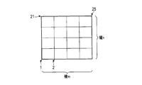
- the set values of the creation points of the radar chart L1 are set values n and m (divided with the vertical axis being n and the horizontal axis being m) for dividing the evaluation area (game surface) at equal intervals.
- the creation point of the radar chart L1 is not limited to the set value for dividing the region at equal intervals, and can be arbitrarily set.
- the processor 61 acquires information of the solid angle database 64a indicating the solid angle of the light emitting surface with high luminance (300,000 cd / m ⁇ 2 or more) in one projector. (Step S112). Further, the processor 61 acquires information (design information of each projector) such as an installation position and aiming (vertical angle and horizontal angle) related to each projector used for the illumination design of the lighting system to be evaluated (step S113). The processor 61 may read the design information of the projector from the setting memory 64, acquire it from an external device via the communication unit 69, or acquire a value input to the operation unit 53. Also good.
- the processor 61 sets the creation points (total number X) of the radar chart L1 based on the set values of the creation points of the radar chart L1 (step S114). When it is set to divide the area to be evaluated into n vertical axes and m horizontal axes, the processor 61 calculates each creation point from the size of the entire area to be evaluated.
- FIG. 26 is a diagram illustrating an example in which an area to be evaluated is divided into five vertical axes and five horizontal axes. In the example shown in FIG. 26, the area to be evaluated is divided at equal intervals by five vertical axes and five horizontal axes.
- the processor 61 performs processing for calculating data for generating the chart graph L1a (solid angle of the high-luminance light-emitting surface in each direction) for the x-th creation point (step S117).
- the processor 61 calculates the solid angle of the high-luminance light emitting surface with respect to the aiming of each projector based on the positional relationship between each projector 2 and the creation point in each set azimuth, and the high-intensity by all the calculated projectors 2.
- the solid angle of the light emitting surface is integrated.
- the processor 61 sequentially increases the brightness (30 in each projector 2 from the azimuth angle 0 °.
- the solid angle of the light emitting surface of 10,000 cd / m ⁇ 2 or more) is calculated, and the solid angle of the light emitting surface having a high luminance of 2 minutes for all projectors is integrated. Further, the processor 61 may calculate the solid angle of the light emitting surface with high brightness within the range of the effective visual field of the person for each direction.
- the processor 61 creates a data table 65a for storing the solid angle for each creation point and azimuth in the data memory 65, and the calculation result (high luminance light-emitting surface The value obtained by integrating the solid angle) is stored in the data table 65a (step S18).
- the data table 65a for storing the solid angle for each creation point and orientation may be created in a memory such as the RAM 62.
- FIG. 27 is an example of the data table 65a.
- the processor 61 calculates the solid angle of the high-luminance light-emitting surface in each direction for each set angle pitch for each creation point, and stores the calculated solid angle in the data table 65a.
- the data table 65a stores the solid angle of the high-luminance light emitting surface in each azimuth every 30 ° with respect to 25 creation points.
- the processor 61 can create a radar chart L1 for each creation point based on the information stored in the data table 65a.
- the processor 61 creates a radar chart L1 for each creation point (step S120).
- the processor 61 creates a radar chart L1 at each creation point based on the data stored in the data table 65a.
- the processor 61 creates the chart graph L1a at each creation point based on the data of each orientation at each creation point stored in the data table 65a, and sets the threshold value for the high-intensity solid angle at each creation point. Based on this, a threshold curve L1b is created.
- the processor 61 displays the created radar chart L1 on the display unit 52 (step S121). Further, the processor 61 may output the created radar chart L1 to the external device through the communication unit 69. Note that the processor 61 may not only display the radar chart L1 in the illumination system S but also display it in comparison with the radar chart L1 in another system such as an existing illumination system.
- FIG. 28 is a diagram showing a display example of the created radar chart L1.
- FIG. 28 is a display example in which the radar chart L1 indicating the lighting environment by the lighting system to be evaluated is compared with the radar chart of the lighting environment by another lighting system.
- the radar chart L1 in the illumination system S to be evaluated and the radar chart in the conventional system are displayed side by side.
- not only the radar chart L1 but also the luminance distribution image in the direction in which the solid angle of the high-luminance light emitting surface reaches a peak is binarized with a threshold for high-luminance determination. The binarized image is displayed.
- the evaluator intuitively recognizes how the size of the high-luminance light-emitting surface in all directions of the illumination system to be evaluated has changed compared to the conventional system by using the radar chart L1. it can. Further, according to the display example shown in FIG. 28, it is also possible to specifically visually recognize the distribution of the high-luminance light emitting surface in the direction in which the size of the high-luminance light emitting surface reaches a peak by the binary image. As a result, it is possible to provide an evaluation tool that can accurately support lighting design and adjustment work.
- the conventional system is an illumination system (HID environment) in which a projector of an HID lamp is arranged
- the system to be evaluated is an illumination system in which an LED projector whose reflector is a reflector is arranged.
- the brightness of the LED environment is high (300,000 cd / m ⁇ ) regardless of the position on the surface where the competition is performed. It is possible to specifically show that the solid angle of the light emitting surface (2 or more) is small and can be played comfortably.
- the threshold curve L1b is set to the solid angle of the sun (for example, 0.000068 to 0.000070 sr)
- the chart graph in the radar chart L1 By indicating that L1a is within the threshold curve L1b, it is possible to clearly indicate that the solid angle of the high-luminance light-emitting surface is smaller than the solid angle of the sun in any direction, and the competition is more than equivalent to the daytime competition. It can be shown that the lighting environment can be.
- the solid angle of the high-luminance light emitting surface in all directions is Adjustment (design) is made so as to be less than a predetermined solid angle.
- the lighting system which concerns on embodiment can provide the lighting environment which can perform a game
- the illumination system is designed or adjusted so that the solid angle of the high-luminance light emitting surface is less than a predetermined solid angle within the effective field of view in all directions.
- the lighting system which concerns on embodiment can provide the lighting environment which can compete comfortably in the visual field of the person in a competition area.
- the illumination system is configured such that each projector is an LED projector, and the threshold for a high-intensity solid angle is a solid angle of a high-luminance light emitting surface when each projector is an HID projector, and high-intensity light emission in each direction It is designed or adjusted so that the solid angle of the surface is less than the solid angle of the light emitting surface with high luminance when the HID projector is used.
- the illumination system configured with the LED projector can make the solid angle of the light emitting surface with high brightness in each direction smaller than the illumination system configured with the HID projector, and is more comfortable than the illumination system configured with the HID projector.
- a lighting environment that can be used for competitions can be provided.
- the lighting system is designed so that the threshold for the high-intensity solid angle is the solid angle of the sun, which is a representative of high-intensity, and the solid angle of the high-luminance light emitting surface in each direction is less than the solid angle of the sun. Or adjusted. Accordingly, it is possible to provide a lighting environment in which a game can be performed with a comfort equal to or higher than that in a case where the game is performed under the sun.
- information processing apparatus is toward several directions from arbitrary positions in the irradiation surface as a competition area.
- the solid angle of the high-luminance light-emitting surface which is equal to or higher than the predetermined luminance when the light-emitting surface of the lighting device is observed, is calculated for each direction of the plurality of directions, and the high-intensity at each direction from the arbitrary position based on the calculation result
- the information indicating the solid angle of the light emitting surface is displayed on the display unit or output to an external device.
- the evaluator who evaluates the lighting environment can present the information as information for easily recognizing the solid angle of the high-luminance light emitting surface in each direction, and the lighting environment can be easily designed and adjusted.
- the information processing apparatus calculates the solid angle of the light emitting surface with high brightness within the range of the effective visual field for each of the directions. Thereby, the information processing apparatus can present the solid angle of the high-luminance light emitting surface in the field of view of the person in the competition area. As a result, it is possible to evaluate a lighting environment in which a player can enjoy a game while paying attention to a person's visual field, and lighting design and adjustment based on the evaluation of such a lighting environment can be performed.
- the information processing apparatus refers to a data table indicating the solid angle of a high-luminance light-emitting surface in one lighting device for each of a plurality of vertical angles and a plurality of horizontal angles. The solid angle is calculated. Thereby, the information processing apparatus according to the embodiment can calculate the solid angle of the light emitting surface with high brightness in each direction at high speed. As a result, even when evaluating the solid angle of the high-luminance light-emitting surface at a plurality of positions, the solid angle of the high-luminance light-emitting surface in each direction at each position can be presented at high speed. The lighting environment can be evaluated and design and adjustment based on the evaluation can be performed quickly.
- the information processing apparatus displays the solid angle of the high-luminance light emitting surface in each direction using a radar chart graph.
- the information processing apparatus according to the embodiment can present the solid angle of the high-luminance light emitting surface in each direction as information that can be intuitively recognized.
- the evaluator can easily evaluate the solid angle of the high-luminance light-emitting surface, and can support design and adjustment based on such evaluation.
- the information processing apparatus 50 according to the present embodiment has a function of providing information for evaluating glare as a second evaluation method for evaluating the lighting environment for the lighting system S.
- the information processing apparatus 50 calculates the evaluation value of glare as a second evaluation method for evaluating the illumination environment by the illumination system S according to the embodiment.
- the evaluation value of glare is not an evaluation value that depends only on the size of the high-luminance light-emitting surface determined by one threshold (predetermined threshold), but the appearance of the visual target (ball) according to the luminance of each pixel. It is calculated as an index indicating the difficulty.
- FIG. 29A is an example of a first luminance distribution image
- FIG. 29B is an example of a second luminance distribution image.
- the first and second luminance distribution images are each represented by a total of 9 pixels of 3 ⁇ 3, and the luminance of the center pixel is 300,000 cd / m ⁇ 2.
- the first luminance distribution image and the second luminance distribution image are different in luminance of each pixel other than the center.
- the threshold for high luminance determination is 300,000 cd / m ⁇ 2
- only the central pixel portion is determined to be a high luminance light emitting surface. That is, if the evaluation is performed only with the threshold value for determining the high luminance, the first luminance distribution image and the second luminance distribution image are evaluated in the same manner.
- the experimental results shown in FIG. 14 indicate that the ball may be evaluated to appear to disappear even with a luminance of less than 30 cd / m ⁇ 2.
- the experimental results shown in FIG. 14 vary depending on individual differences that the ball appears to disappear with a probability of 10% to less than 100% at a luminance of 30,000 cd / m 2 or more and less than 300,000 cd / m 2.
- a certain glare evaluation result is obtained.
- the experimental result shown in FIG. 14 (relation between luminance and glare evaluation) can be expressed by the following relational expression (1) indicating an approximate curve.
- the above equation (1) is an S-shaped function that mathematically represents the approximate curve obtained from the experimental results shown in FIG.
- x is the luminance
- f (x) is the glare evaluation value (glare value).
- An expression indicating the relationship between the luminance and the glare evaluation value is referred to as a glare evaluation function.
- the glare evaluation function of the above formula (1) is a function in which the maximum value of f (x) is “1” and the minimum value is “0”. As “x” as luminance increases, f (x) as a glare value increases. x) increases.
- the glare value (f (x)) is “about 0.3” when the luminance is “50,000 cd / m 2”, and the luminance “100,000 cd / "approx. 0.7” for m ⁇ 2; “approx. 0.9” for luminance "200,000 cd / m ⁇ 2"; “approx. 1” for luminance "300,000 cd / m ⁇ 2" .
- the information processing apparatus 50 converts the luminance of each pixel in the luminance distribution image of the light emitting surface into a glare evaluation value based on the glare evaluation function, and calculates a value obtained by integrating the glare evaluation values. It is calculated as the glare value of the entire surface (glare evaluation value for the entire light emitting surface).
- FIG. 30A is an example of the glare value obtained from the first luminance distribution image shown in FIG. 29A.
- FIG. 30B is an example of the glare value obtained from the second luminance distribution image shown in FIG. 29B.
- the information processing apparatus 50 converts the luminance of each pixel in the first luminance distribution image shown in FIG. 29A into a glare evaluation value as shown in FIG. 30A using the glare evaluation function.
- the information processing apparatus 50 integrates the glare evaluation values of each pixel.
- the information processing apparatus 50 converts the luminance of each pixel in the second luminance distribution image shown in FIG. 29B into a glare evaluation value as shown in FIG. 30B using the glare evaluation function.
- the information processing apparatus 50 integrates the glare evaluation values of each pixel.
- the light emitting surface (light emitting surface evaluated to be difficult to play) having a high probability of hindering the appearance of the ball is more than the light emitting surface that is the second luminance distribution image shown in FIG. 29B.
- FIG. 29A is also a light emitting surface that becomes the first luminance distribution image shown in FIG. 29A.
- the glare evaluation function (S-shaped function) shown in the above formula (1) is obtained from one experimental result, and the glare evaluation function is not limited to the formula (1). That is, the glare evaluation function may be obtained from various experimental results and conditions.
- the glare evaluation value for evaluating the entire light emitting surface is a value obtained by integrating the glare values of each pixel obtained by the glare evaluation function, but is the number of pixels obtained by integrating the values obtained by integrating the glare values of each pixel. It is good also as the value which remove
- the value obtained by dividing the glare value of each pixel by the number of pixels is used as the glare evaluation value, for example, in the first luminance distribution image shown in FIG. 29A, the glare evaluation value is “0.87”.
- the second luminance distribution image shown in FIG. 29B has the glare evaluation value “0.64”.
- the information processing apparatus 50 has a function of displaying the above-described glare evaluation value on the radar chart L2 in the second evaluation method.
- the radar chart L2 is a diagram showing glare evaluation values in all directions from an arbitrary observation position in a stadium where the lighting system S is installed. That is, as the second evaluation method, the information processing apparatus 50 creates a radar chart L2 that indicates glare evaluation values in all directions at a plurality of observation positions.
- the radar chart L2 indicating the glare evaluation value is generated in the same manner as the radar chart L1 shown in FIGS. 21, 22, 23A, or 23B described in the first evaluation method.
- FIG. 21 shows an example of setting the creation points of the radar chart L2
- FIG. 22 shows an example of the radar chart L2. That is, the information processing apparatus 50 creates a plurality of radar charts L at a plurality of observation positions including a competition area (irradiation surface) as shown in FIG.
- the creation point of the radar chart L2 may be set at an arbitrary position similarly to the creation point of the radar chart L1 described above.
- Each radar chart L2 displays a chart graph L2a indicating the evaluation value of glare in each direction from the observation position with the observation position in the competition area as the center, as shown in FIG.
- the distance from the center represents the magnitude of the glare evaluation value.
- the chart graph L2a is a curve obtained by connecting evaluation values of glare in each direction.
- the evaluation value of the glare in each direction displayed as the chart graph L2a is obtained by converting each pixel of the luminance distribution image of the light emitting surface formed by each projector 2 in each direction into a glare value, and for each pixel in the range to be evaluated. Calculate based on the glare value. Further, the glare evaluation value in each direction may be calculated within the range of the effective visual field of the person toward each direction.
- the evaluation value of glare in each direction may be calculated based on the glare value by the light emitting surface of each projector 2 in each direction.
- the glare value due to the light emitting surface of each projector 2 may be determined based on information stored in a later-described glare value database 64b and design information indicating the installation position and aiming of each projector 2.
- the glare evaluation value in each direction may be calculated based on the glare value by the light emitting surface of each projector 2 that is within the range of the effective visual field of the person for each direction. A method for creating the radar chart L2 using the glare value database 64b will be described in detail later.
- the radar chart L2 displays a target value curve L2b together with the chart graph L2a.
- the target value curve L2b is a target value for the glare evaluation value, and is a value set in advance according to the experimental results, design conditions, and the like.
- the target value for the glare evaluation value indicated by the target value curve L2b may be set based on the daytime environment using the sun as a light source, or may be compared with other (conventional) lighting systems or the like.
- the target value may be set based on the glare evaluation value in the lighting environment.
- the target value for the glare evaluation value shown as the target value curve L2b may not be a constant value for all directions.
- the target value for the evaluation value of glare may be set to be different for each direction as in the radar charts L2 ′ and L2 ′′ shown in FIGS. 23 (a) and 23 (b).
- the target value curve L2b ′ shown in FIG. 23A decreases the target value for the glare evaluation value in the a direction, and increases the target value for the glare evaluation value in the direction opposite to the a direction as well as in the a direction. This is an example. Accordingly, it is possible to support a design or adjustment that reduces the glare evaluation value in the a direction and allows the glare evaluation value to increase in the direction opposite to the a direction.
- the target value curve L2b ′′ shown in FIG. 23 (b) is composed of a semicircle centering on a certain direction (for example, a direction) and a semicircle centering on the opposite direction. Even with such a target value, it is possible to support a design or adjustment that allows the target value for the glare evaluation value to be small in the a direction and allows the glare evaluation value to be large in the direction opposite to the a direction. . If a target value as shown by the target value curve L2b ′ in FIG. 23 (a) or the target value curve L2b ′′ in FIG. 23 (b) is set, the flyball flies from the a direction (or around the a direction).
- the target value for the glare evaluation value can be set to an arbitrary value for each direction, and the target value curve L2b as a result may be an arbitrary shape.
- the target value curve L2b may be an ellipse or a polygon such as a triangle or a rectangle.
- FIG. 31 is a diagram illustrating a configuration example of the glare value database 64b.
- the glare value database 64b stores information indicating the glare value of the light emitting surface for each of various angles (vertical angle and horizontal angle) in one projector viewed from a certain distance.
- the glare value database 64b indicates the glare value when the angle in the vertical direction is every 10 degrees and the angle in the horizontal direction is every 10 degrees.
- the glare value on the light emitting surface of a certain projector can be determined from the glare value database 64b based on the horizontal angle and the vertical angle with respect to the projector.
- the processor 61 calculates the horizontal angle and the vertical angle with respect to the projector based on the relationship between the installation position and installation direction of one projector and the observation position, and the light emitting surface from the glare value database 64b based on the calculated horizontal angle and vertical angle.
- the glare value is calculated.
- the glare value database is corrected by the distance between the viewpoint and the projector.
- the installation position and aiming (vertical angle and horizontal angle) of each projector 2 can be acquired as design information.
- the design information related to each projector 2 may be stored in advance in the setting memory 64 or the data memory 65, may be acquired via the communication unit 69, or may be input via the operation unit 53.
- the setting memory 64 may be provided with a database of glare values for each type of projector.
- FIG. 32 is a flowchart for explaining a radar chart L2 creation process by the information processing apparatus 50.
- the processor 61 executes a radar chart L2 creation process by executing a radar chart creation process program stored in a program memory such as the ROM 63 or the data memory 65.
- the processor 61 first sets information (conditions) for creating the radar chart L2 (step S211).
- Information (conditions) for creating the radar chart L2 may be information stored in the setting memory 64, information input from an external device through the communication unit 96, or the like. Information based on information input by the unit 53 may be used.
- the information (conditions) for creating the radar chart L2 includes, for example, the setting value of the creation point (observation position) of the radar chart L2, the angle pitch with respect to the direction in which the glare evaluation value is calculated, and the viewpoint height at the observation position. It is information such as the elevation angle of the line of sight, the distance between the viewpoint and the illumination column or the projector.
- the set values of the creation points of the radar chart L2 are set values n and m (divided with n on the vertical axis and m on the horizontal axis) for dividing the evaluation area (the competition surface) at equal intervals.
- the creation point of the radar chart L2 is not limited to the set value for dividing the region at equal intervals, and can be set arbitrarily.
- the processor 61 acquires information on the glare value database 64b indicating the glare value of the light emitting surface of one projector (step S212). Further, the processor 61 acquires information (design information of each projector) such as an installation position and aiming (vertical angle and horizontal angle) related to each projector used for illuminance design of the lighting system to be evaluated (step 213). The processor 61 may read the design information of the projector from the setting memory 64, acquire it from an external device via the communication unit 69, or acquire a value input to the operation unit 53. Also good.
- the processor 61 sets the creation points (total number X) of the radar chart L2 based on the set values of the creation points of the radar chart L2 (step S214).
- the processor 61 calculates each creation point from the size of the entire area to be evaluated.
- the area to be evaluated may be an area divided by 5 vertical axes and 5 horizontal axes as shown in FIG.
- the processor 61 creates 25 points at which the vertical axis and the horizontal axis intersect at the creation points of the radar chart L2.
- the processor 61 When the variable x is incremented, the processor 61 performs a process of calculating data (glare value in each direction) for generating the chart graph L2a for the x-th creation point (step S217).
- the processor 61 calculates the glare value by the light emitting surface of each projector according to aiming based on the positional relationship between each projector 2 and the creation point in each set azimuth, and glare by the light emitting surfaces of all the calculated projectors 2 Accumulate values.
- the processor 61 calculates the glare value in each projector 2 in order from the azimuth angle 0 °. Then, the glare evaluation values in all directions are calculated by integrating the glare values of all the projectors 2. The processor 61 may calculate the glare evaluation value in each azimuth by integrating the glare values in the range of the effective visual field of the person for each azimuth.
- the processor 61 When the evaluation value of the glare in each azimuth is calculated, the processor 61 creates a data table 65a for storing the glare value for each creation point and azimuth in the data memory 65, and the calculation result (calculation result of the glare value) is stored in the data table 65a. (Step S218).
- the data table 65a for storing glare evaluation values for each creation point and orientation may be created in a memory such as the RAM 62.
- FIG. 33 is an example of the data table 65b.
- the processor 61 calculates an evaluation value of glare in each azimuth for each set point for each created point, and stores the calculated evaluation value of glare in the data table 65b.
- the data table 65b stores glare evaluation values in each direction every 30 ° with respect to 25 created points.
- the processor 61 can create a radar chart L2 for each creation point based on the information stored in the data table 65b.
- the processor 61 creates a radar chart L2 for each creation point (step S220).
- the processor 61 creates a radar chart L2 at each creation point based on the data stored in the data table 65b.
- the processor 61 creates a chart graph L2a at each creation point based on the data of each orientation at each creation point stored in the data table 65b, and sets the target value based on the target value for the glare evaluation value at each creation point.
- a curve L2b is created.
- the processor 61 displays the created radar chart L2 on the display unit 52 (step S221). Further, the processor 61 may output the created radar chart L2 to an external device through the communication unit 69. The processor 61 may not only display the radar chart L2 in the lighting system S but also display it in comparison with a radar chart in another system such as an existing lighting system.
- FIG. 34 is a diagram showing a display example of the created radar chart L2.
- FIG. 34 is a display example in which the radar chart L2 indicating the lighting environment by the lighting system to be evaluated is compared with the radar chart of the lighting environment by another lighting system.
- the radar chart L2 in the illumination system S to be evaluated and the radar chart in the conventional system are displayed side by side.
- the information processing apparatus 50 has not only a radar chart indicating the glare evaluation value in each direction but also a peak (maximum solid angle of the high-luminance light emitting surface) peak (maximum). ) Is displayed on the display device in a color image in which each pixel of the luminance distribution image in the direction of () is displayed in a color corresponding to the evaluation value of glare.
- the evaluator can intuitively determine how the glare evaluation value in all directions of the lighting system to be evaluated has changed compared to another system (or a conventional system) using a radar chart. Can be recognized.
- the distribution of glare evaluation values can be intuitively recognized by a color image. As a result, it is possible to provide an evaluation tool that can accurately support lighting design and adjustment work.
- the conventional system is an illumination system (HID environment) in which a projector of an HID lamp is arranged
- the system to be evaluated is an illumination system in which an LED projector whose reflector is a reflector is arranged.
- LED environment Assume that (LED environment).
- the radar charts of both it is concretely that the glare evaluation value is small and it can be played comfortably no matter which position on the surface where the LED environment is playing, the light emitting surface of the projector is small. Can be presented.
- the chart graph L2a is the target value in the radar chart L2.
- the information processing apparatus evaluates the lighting environment by the lighting system in which a plurality of lighting devices are arranged, and therefore the light emitting surface of the lighting device from any observation position on the irradiation surface as a competition area.
- the glare evaluation value is calculated by integrating the glare values of each pixel in the luminance distribution image of the light emitting surface when the light emission surface is observed, and the calculated glare evaluation value is glare when the light emitting surface of the lighting device is observed from the observation position. Is displayed as a value to be evaluated on the display unit or output to an external device. Thereby, the evaluator who evaluates the illumination environment can recognize the glare at the observation position by an objective numerical value, and as a result, the design and adjustment of the illumination environment are facilitated.
- the information processing apparatus evaluates an illumination environment by an illumination system in which a plurality of illumination devices are arranged, and the illumination device is directed from a plurality of observation positions on an irradiation surface as a competition area toward a plurality of directions.
- the evaluator who evaluates the lighting environment can recognize the evaluation value of the glare in each direction as an objective numerical value, and the design and adjustment of the lighting environment are facilitated.
- the information processing device calculates the evaluation value of the glare on the light emitting surface within the range of the effective visual field for the light emitting surface in each direction.
- the information processing apparatus can present the evaluation value of the glare of the light emitting surface in the field of view of the person in the competition area.
- the information processing apparatus calculates a glare evaluation value in each direction with reference to a database indicating the glare value of the light emitting surface in one lighting device for each of a plurality of vertical angles and a plurality of horizontal angles.
- the information processing apparatus can calculate the evaluation value of the glare in each direction at high speed.
- glare evaluation values in each orientation at each observation position can be presented at high speed, and the illumination environment at multiple observation positions can be evaluated and evaluated. The design and adjustment based on can be done quickly.
- the information processing apparatus displays the glare value of the light emitting surface in each direction using a radar chart graph.
- the information processing apparatus can present the glare value of the light emitting surface in each direction as information that can be intuitively recognized.
- the evaluator can easily evaluate the glare value of the light emitting surface in the stadium (irradiated surface), and can support design and adjustment based on such evaluation.
Abstract
Provided is a lighting system capable of achieving lighting whereunder competitions can be performed comfortably. According to an embodiment of this invention, the surface to be illuminated for the lighting system is the interior of a competition venue. The lighting system is equipped with a plurality of lighting instruments. Each of the plurality of lighting instruments has a light-emitting surface that emits the light from a light source. The plurality of lighting instruments are disposed in such a manner that, when the light-emitting surface is observed from an arbitrary position on the surface to be illuminated, the solid angle of a light emitting surface having a high brightness of a predetermined brightness or greater is smaller than a predetermined solid angle.
Description
本発明の実施形態は、照明環境の評価方法に関する。
Embodiment of this invention is related with the evaluation method of lighting environment.
夜間に競技が可能な大型の競技場などには、複数の大型照明装置を配置した照明システムが設置される。競技場に設ける照明システムを構成する各大型照明装置は、照射面(例えば、競技場における競技を行う領域)の照度を所定の規格に基づく所定の値以上になるように設計される(例えば、JISZ9127「スポーツ照明基準」)。例えば、屋外の大型の競技場においては、各大型照明装置は、発光面が地上数十メートルの位置となるので、照射面を所定の照度するために、発光面が非常に高い輝度となる。
In large stadiums that can compete at night, a lighting system with multiple large lighting devices will be installed. Each large illuminating device constituting the lighting system provided in the stadium is designed so that the illuminance of the irradiation surface (for example, the area where the competition is performed in the stadium) is equal to or higher than a predetermined value based on a predetermined standard (for example, JISZ9127 “Sports Lighting Standard”). For example, in a large outdoor stadium, each large illuminating device has a light emitting surface at a position several tens of meters above the ground, so that the light emitting surface has a very high luminance in order to provide a predetermined illuminance on the irradiated surface.
しかしながら、各大型照明装置の発光面の輝度が高いと、競技場で行われる競技の妨げになることがある。従来、上述の規格によれば、照明器具からの強い光が眼に入る光による影響を測定する方法は、観測者の視線方向は水平より2°下方を向き、測定評価することとされているが、各大型照明装置の発光面を直接観察(直視)する場合については、規格などで定められた一般的な指標が無く、詳細には検討されていない。このため、競技場に設置する照明システムは、競技者が快適に競技を行えるように各大型照明装置の発光面の輝度や高輝度の面の大きさなどが調整されることが望まれている。
However, if the brightness of the light emitting surface of each large illuminating device is high, it may interfere with the competition held at the stadium. Conventionally, according to the above-mentioned standard, the method for measuring the influence of the strong light from the lighting fixture due to the light entering the eye is to measure and evaluate the observer's line-of-sight direction 2 ° below the horizontal. However, in the case of directly observing (directly viewing) the light emitting surface of each large illuminating device, there is no general index defined by standards or the like, and it has not been studied in detail. For this reason, the lighting system installed in the stadium is desired to adjust the brightness of the light-emitting surface and the high-luminance surface of each large lighting device so that the athlete can comfortably compete. .
本発明の目的は、競技者が快適に競技を行える照明を実現する照明システム、照明システムによる照射面における競技のし易さを評価できる照明環境の評価方法、および、その評価方法に基づいて設計された照明装置を提供することである。
An object of the present invention is to provide an illumination system that realizes lighting that allows a player to comfortably play a game, a lighting environment evaluation method that can evaluate easiness of playing on an irradiation surface by the lighting system, and a design based on the evaluation method Provided is a lighting device.
本発明は、競技者が快適に競技を行える照明を実現する照明システム、照明システムによる照射面における競技のし易さを評価できる照明環境の評価方法、および、その評価方法に基づいて設計された照明装置を提供することができる。
The present invention is designed based on a lighting system that realizes lighting that allows a player to comfortably play a game, a lighting environment evaluation method that can evaluate the ease of playing on the irradiated surface by the lighting system, and the evaluation method. A lighting device can be provided.
以下で説明する実施形態に係る照明システム(S)は、競技場内を照射面とし、複数の照明機器(2)を具備する。前記複数の照明機器(2)は、光源(21)からの光を放射する発光面を有する。前記複数の照明機器(2)は、前記照射面における任意の観察位置から発光面が観察された場合に、所定輝度以上となる高輝度の発光面の立体角が所定の立体角未満となるように配置される。
The lighting system (S) according to the embodiment described below includes a plurality of lighting devices (2) with the inside of the stadium as an irradiation surface. The plurality of lighting devices (2) have a light emitting surface that emits light from the light source (21). When the light emitting surface is observed from an arbitrary observation position on the irradiation surface, the plurality of lighting devices (2) has a solid angle of a high-luminance light emitting surface that is equal to or higher than a predetermined luminance, less than a predetermined solid angle. Placed in.
また、以下で説明する実施形態に係る照明システム(S)の前記複数の照明機器(2)は、前記光源(21)からの光を反射するリフレクター(22)を有する。
Further, the plurality of lighting devices (2) of the lighting system (S) according to the embodiment described below includes a reflector (22) that reflects light from the light source (21).
また、以下で説明する実施形態に係る照明システムの前記複数の照明機器(2)は、人物の有効視野の範囲内において高輝度の発光面の立体角が前記所定の立体角未満となるように配置される。
Further, in the plurality of lighting devices (2) of the lighting system according to the embodiment described below, the solid angle of the high-luminance light emitting surface is less than the predetermined solid angle within the range of the effective visual field of the person. Be placed.
また、以下で説明する実施形態に係る照明システム(S)は、前記所定の立体角が太陽の立体角を基準に設定される。
In the illumination system (S) according to the embodiment described below, the predetermined solid angle is set with reference to the solid angle of the sun.
また、以下で説明する実施形態に係る照明システム(S)は、前記所定の立体角が特定の速度で移動する視対象が前記所定の輝度以上の高輝度となる面によって視認できなくなる時間が所定時間未満となる立体角である。
In addition, the illumination system (S) according to the embodiment described below has a predetermined time during which the visual target in which the predetermined solid angle moves at a specific speed becomes invisible due to a surface having a high luminance equal to or higher than the predetermined luminance. The solid angle is less than time.
また、以下で説明する実施形態に係る照明システム(S)の前記複数の照明機器(2)は、前記照射面における任意の観察位置から複数の方位に向かって発光面が観察された場合に、全ての方位において所定輝度以上となる高輝度の発光面の立体角が所定の立体角未満となるように配置される。
In addition, the plurality of illumination devices (2) of the illumination system (S) according to the embodiment described below, when a light emitting surface is observed from a plurality of observation positions on the irradiation surface toward a plurality of directions, The solid angle of the high-luminance light emitting surface that is equal to or higher than the predetermined luminance in all directions is arranged to be less than the predetermined solid angle.
以下で説明する実施形態に係る照明環境の評価方法(第1の評価方法)は、発光面を有する複数の照明機器(2)を配置した照明システム(S)による照明環境を評価する方法である。第1の評価方法は、照射面におけるある観察位置から複数の方位に向かって照明機器の発光面を観察した場合に所定輝度以上となる高輝度の発光面の立体角を前記複数の方位の各方位について算出し、算出した各方位についての高輝度の発光面の立体角を示す情報を表示する。
A lighting environment evaluation method (first evaluation method) according to an embodiment described below is a method of evaluating a lighting environment by a lighting system (S) in which a plurality of lighting devices (2) having a light emitting surface are arranged. . In the first evaluation method, a solid angle of a high-luminance light-emitting surface that is equal to or higher than a predetermined luminance when the light-emitting surface of the lighting device is observed from a certain observation position on the irradiation surface toward a plurality of directions is set to each of the plurality of directions. The direction is calculated, and information indicating the solid angle of the high-luminance light emitting surface for each calculated direction is displayed.
また、以下で説明する実施形態に係る第1の評価方法は、前記高輝度の発光面の立体角を有効視野の範囲内で算出する。
Also, in the first evaluation method according to the embodiment described below, the solid angle of the high-luminance light emitting surface is calculated within the range of the effective visual field.
また、以下で説明する実施形態に係る第1の評価方法は、前記高輝度の発光面の立体角を、個々の照明機器における高輝度の発光面の立体角を複数の鉛直角、及び、複数の水平角毎に示すデータベース(64a)を参照して算出する。
Further, in the first evaluation method according to the embodiment described below, the solid angle of the high-luminance light-emitting surface, the solid angle of the high-luminance light-emitting surface in each lighting device, a plurality of vertical angles, and a plurality of It calculates with reference to the database (64a) shown for every horizontal angle.
また、以下で説明する実施形態に係る第1の評価方法は、各方位についての高輝度の発光面の立体角を示すレーダーチャートグラフ(L1)を表示する。
In addition, the first evaluation method according to the embodiment described below displays a radar chart graph (L1) indicating the solid angle of the high-luminance light emitting surface for each direction.
以下で説明する実施形態に係る照明環境の評価方法(第2の評価方法)は、発光面を有する複数の照明機器(2)を配置した照明システム(S)による照明環境を評価する方法である。第2の評価方法は、ある観察位置からある方位に向かって照明機器の発光面を観察した場合の輝度分布画像における各画素の輝度を、輝度とグレア値との関係を示す評価関数に基づいて、グレア値に変換し、前記輝度分布画像における評価対象の範囲内にある各画素のグレア値に基づいて前記観察位置から前記方位におけるグレアの評価値を算出する。
A lighting environment evaluation method (second evaluation method) according to an embodiment described below is a method of evaluating a lighting environment by a lighting system (S) in which a plurality of lighting devices (2) having light emitting surfaces are arranged. . In the second evaluation method, the luminance of each pixel in the luminance distribution image when the light emitting surface of the lighting device is observed from a certain observation position toward a certain direction is based on an evaluation function indicating the relationship between the luminance and the glare value. The glare value is converted into a glare value, and the glare evaluation value in the azimuth is calculated from the observation position based on the glare value of each pixel within the range to be evaluated in the luminance distribution image.
また、以下で説明する実施形態に係る第2の評価方法は、前記評価対象の範囲が有効視野の範囲である。
Further, in the second evaluation method according to the embodiment described below, the range of the evaluation target is an effective visual field range.
また、以下で説明する実施形態に係る第2の評価方法は、前記グレア値が、個々の照明機器の発光面における複数の鉛直角、及び、複数の水平角毎のグレア値を格納したデータベース(64b)を参照して、前記方位における評価対象の範囲内にある各照明機器の発光面ごとに判定され、前記グレアの評価値が、前記判定した評価対象の範囲内にある各照明機器の発光面のグレア値に基づいて算出される。
The second evaluation method according to the embodiment described below is a database in which the glare value stores a plurality of vertical angles and a plurality of horizontal angle glare values on the light emitting surface of each lighting device ( 64b), it is determined for each light emitting surface of each lighting device within the range of the evaluation target in the azimuth, and the glare evaluation value is the light emission of each lighting device within the determined range of the evaluation target Calculated based on the glare value of the surface.
また、以下で説明する実施形態に係る第2の評価方法は、さらに、前記観察位置から複数の方位に向かって照明機器の発光面を観察した場合における前記複数の方位における発光面に対するグレアの評価値をそれぞれ算出し、前記観察位置から前記複数の方位におけるグレアの評価値を示すレーダーチャートグラフ(L2)を表示する。
Further, in the second evaluation method according to the embodiment described below, the glare is evaluated on the light emitting surface in the plurality of directions when the light emitting surface of the lighting apparatus is observed from the observation position toward the plurality of directions. Each value is calculated, and a radar chart graph (L2) indicating glare evaluation values in the plurality of directions from the observation position is displayed.
また、以下で説明する実施形態に係る照明装置(1)は、前記第1の評価方法又は前記第2の評価方法の少なくとも何れか一方の評価に基づいて設計された照明機器(2)を具備する。
Moreover, the illuminating device (1) which concerns on embodiment described below comprises the illuminating device (2) designed based on evaluation of at least any one of the said 1st evaluation method or the said 2nd evaluation method. To do.
以下、図面を参照しながら、実施形態について詳細に説明する。
本実施形態においては、競技場などに設けた照明システムによる照明環境を評価する評価方法について説明する。
図1は、実施形態に係る照明システムSの構成例を示す図である。
照明システムSは、複数の大型照明装置(以下、照明柱とも称する)1(1a、1b、1c、1d、1e、1f)により構成される。図1に示す照明システムSにおいて、各大型照明装置1は、競技場を取り囲むように配置される。各大型照明装置1は、照射面を照射するための発光面を有し、発光面が競技場内に向けて設置される。照明システムSは、競技場において競技が実施される競技領域を照射面とし、照射面全体が所定の照度となるように設計される。 Hereinafter, embodiments will be described in detail with reference to the drawings.
In the present embodiment, an evaluation method for evaluating a lighting environment by a lighting system provided in a stadium or the like will be described.
FIG. 1 is a diagram illustrating a configuration example of a lighting system S according to the embodiment.
The illumination system S includes a plurality of large illuminating devices (hereinafter also referred to as illumination columns) 1 (1a, 1b, 1c, 1d, 1e, 1f). In the illumination system S shown in FIG. 1, each large illuminatingdevice 1 is arrange | positioned so that a competition field may be surrounded. Each large illuminating device 1 has a light emitting surface for irradiating an irradiation surface, and the light emitting surface is installed in the stadium. The illumination system S is designed so that a competition area where a competition is performed in a stadium is an irradiation surface, and the entire irradiation surface has a predetermined illuminance.
本実施形態においては、競技場などに設けた照明システムによる照明環境を評価する評価方法について説明する。
図1は、実施形態に係る照明システムSの構成例を示す図である。
照明システムSは、複数の大型照明装置(以下、照明柱とも称する)1(1a、1b、1c、1d、1e、1f)により構成される。図1に示す照明システムSにおいて、各大型照明装置1は、競技場を取り囲むように配置される。各大型照明装置1は、照射面を照射するための発光面を有し、発光面が競技場内に向けて設置される。照明システムSは、競技場において競技が実施される競技領域を照射面とし、照射面全体が所定の照度となるように設計される。 Hereinafter, embodiments will be described in detail with reference to the drawings.
In the present embodiment, an evaluation method for evaluating a lighting environment by a lighting system provided in a stadium or the like will be described.
FIG. 1 is a diagram illustrating a configuration example of a lighting system S according to the embodiment.
The illumination system S includes a plurality of large illuminating devices (hereinafter also referred to as illumination columns) 1 (1a, 1b, 1c, 1d, 1e, 1f). In the illumination system S shown in FIG. 1, each large illuminating
照明システムSは、競技者が発光面を直視する可能性がある競技が行われる競技場に設置されるものを想定する。照明システムSが設置される競技場は、例えば、競技中の視対象がボールである、野球、サッカー、ラグビー、テニスなどの競技を行う競技場が想定される。照明システムSが設置される競技場は、特定の競技を行う競技場に限定されるものではない。また、照明システムSが設置される競技場は、屋内であっても良い。以下に説明する実施形態は、主に、競技として野球を行う競技場を想定して説明する。
The lighting system S is assumed to be installed in a stadium where a competition is held in which there is a possibility that the athlete may directly look at the light emitting surface. As the stadium where the lighting system S is installed, for example, a stadium where a target to be viewed during the competition is a ball, such as baseball, soccer, rugby, tennis, and the like is assumed. The stadium where the lighting system S is installed is not limited to a stadium where a specific competition is performed. The stadium where the lighting system S is installed may be indoors. The embodiment described below will be described mainly assuming a stadium where baseball is played as a game.
本実施形態に係る照明システムSは、競技領域内にある箇所から観察者(競技者)が各大型照明装置の各投光器が形成する発光面を直視した場合に、輝度が所定の閾値以上の発光面(高輝度の発光面)の大きさが所定の閾値以下となるように設定される。すなわち、照明システムSを構成する各大型照明装置は、照射面全体を所定の照度以上とすることを前提とし、競技領域内における任意の点(観察位置)から任意の方向を観察した場合の高輝度の発光面の大きさが所定の閾値以下となるように設計又は調整される。
The illumination system S according to the present embodiment emits light with a luminance equal to or higher than a predetermined threshold when an observer (competitor) directly looks at the light emitting surface formed by each projector of each large illuminating device from a location within the competition area. The size of the surface (high luminance light emitting surface) is set to be equal to or less than a predetermined threshold. That is, each large illuminating device that constitutes the illumination system S is based on the premise that the entire irradiation surface has a predetermined illuminance or higher, and is high when observing an arbitrary direction from an arbitrary point (observation position) in the competition area. The luminance light emitting surface is designed or adjusted so that the size of the light emitting surface is a predetermined threshold value or less.
高輝度の発光面は、競技中に視対象となるボールが消えて見える程度に眩しく感じる発光部分である。高輝度の発光面が大きくなると、競技に与える影響が大きくなり、ボールが消えて見える期間が長くなればなるほど、競技者がボールを見失ってしまう可能性が高くなる。従って、ボールが消えて見えるような眩しく感じる発光部分(高輝度の発光面)が競技に大きな影響を与えない程度の大きさ以下とする照明環境が望まれると考えられる。ここでは、ボールが消えて見える程度に眩しく感じることをグレアと称する。
The high-luminance light-emitting surface is a light-emitting part that feels so dazzling that the ball to be viewed disappears during the competition. As the high-luminance light-emitting surface increases, the impact on the game increases, and the longer the period during which the ball appears to disappear, the more likely the player will lose sight of the ball. Therefore, it is considered that an illumination environment is desired in which the light-emitting part (the high-luminance light-emitting surface) that feels dazzling so that the ball appears to disappear does not greatly affect the competition. Here, the glare that makes the ball appear to disappear is called glare.
高輝度の発光面(グレアを生じる発光面)は、所定の閾値(高輝度判定用の閾値)により判定される。所定の閾値(高輝度判定用の閾値)は、高輝度の発光面と判定するための閾値であって、観察者(競技者)が視対象を視認でない(又は競技者が競技をし難い)と評価する輝度に基づいて設定される値である。例えば、野球を行う競技場に設置される照明システムSに対しては、競技場内において競技中にボールが消えて見えると競技者が評価する輝度に基づいて高輝度判定用の閾値が設定される。つまり、高輝度判定用の閾値は、競技者などの人間の主観的な評価に基づいて設定される値であって、競技内容、視対象、照明システムの設置条件、競技場の環境などの様々な要素によって変化する可能性がある。このため、高輝度判定用の閾値は、後述するような実験等に基づいて、実際の運用形態および設計条件などを考慮しつつ設定される。
A high-luminance light-emitting surface (light-emitting surface that produces glare) is determined by a predetermined threshold value (high-luminance determination threshold value). The predetermined threshold value (threshold value for high brightness determination) is a threshold value for determining a light emitting surface with high brightness, and an observer (athlete) does not visually recognize a visual target (or it is difficult for a player to compete). Is a value set based on the luminance to be evaluated. For example, for the lighting system S installed in a stadium where baseball is played, a threshold for high brightness determination is set based on the brightness that the player evaluates when the ball appears to disappear during competition in the stadium. . In other words, the threshold for high brightness determination is a value set based on subjective evaluations of humans such as athletes, and various values such as competition contents, visual objects, lighting system installation conditions, stadium environment, etc. It may change depending on various factors. For this reason, the threshold value for high brightness determination is set in consideration of an actual operation mode, design conditions, and the like based on an experiment or the like described later.
また、高輝度の発光面は、競技場内で行われる競技に与える影響ができるだけ小さくなるように設計される。すなわち、高輝度の発光面は、視対象が視認できなくなる(ボールが消えて見える)部分であるため、競技者が視対象を視認できなくなる期間として許容される範囲の大きさに設計される。本実施形態では、発光面の大きさを立体角で表すものとする。発光面の大きさを立体角で表すと、高輝度の発光面の大きさに対する閾値(高輝度の立体角用の閾値)は、競技者が実際に競技を行うのに支障がない範囲(或いは、許容されるべき範囲)と評価する立体角に基づいて設定される。例えば、野球を行う競技場に設置される照明システムSに対しては、競技中にボールが消えて見える部分が競技する上で許容できると評価される大きさ(立体角)に基づいて高輝度の立体角用の閾値(以下、単に、立体角の閾値とも称する)が設定される。つまり、立体角の閾値は、競技者などの人間の主観的な評価に基づいて設定される値であって、競技内容、視対象の形状、視対象の動き、照明システムの設置条件、競技場の環境、要求される照度などの様々な要素によって変化する可能性がある。このため、立体角の閾値は、後述するような実験等に基づいて、実際の運用形態および設計条件などを考慮しつつ設定される。
In addition, the high-luminance light-emitting surface is designed so that the influence on the competition performed in the stadium is as small as possible. That is, the high-luminance light-emitting surface is designed to have a size that is allowed as a period during which the player cannot visually recognize the visual target because the visual target is not visible (the ball appears to disappear). In the present embodiment, the size of the light emitting surface is represented by a solid angle. When the size of the light emitting surface is represented by a solid angle, the threshold for the size of the high luminance light emitting surface (threshold for the high luminance solid angle) is within a range that does not hinder the player from actually playing the game (or , A range to be allowed) and a solid angle to be evaluated. For example, for the lighting system S installed in a stadium where baseball is played, the brightness is high based on the size (solid angle) that is evaluated as acceptable for playing the part where the ball appears to disappear during the game. The threshold for the solid angle (hereinafter also simply referred to as the solid angle threshold) is set. In other words, the solid angle threshold is a value that is set based on the subjective evaluation of humans such as athletes, and includes the content of the competition, the shape of the visual target, the movement of the visual target, the installation conditions of the lighting system, the stadium, It may change depending on various factors such as the environment and required illuminance. For this reason, the threshold value of the solid angle is set in consideration of an actual operation mode, design conditions, and the like based on an experiment or the like to be described later.
図2は、実施形態に係る照明システムSを構成する各大型照明装置1の構成例を示す図である。
大型照明装置1は、複数の投光器(照明機器)2(2a、2b、…)、架台3、および支持柱(ポール)4などを有する照明装置である。複数の投光器2は、1又は複数の光源からの光を放射する照明器具である。各投光器2は、例えば、光源にLEDを用いた器具光束10000ルーメン以上のLED投光器である。架台3は、複数の投光器2が取り付けられるものであり、支持柱4に設置される。支持柱4は、複数の投光器2が取り付けられた架台3を所定の高さで支持する。 FIG. 2 is a diagram illustrating a configuration example of each large-sized lighting device 1 configuring the lighting system S according to the embodiment.
The large illuminatingdevice 1 is an illuminating device having a plurality of projectors (illuminating devices) 2 (2a, 2b,...), A pedestal 3, a support column (pole) 4, and the like. The plurality of projectors 2 are luminaires that emit light from one or more light sources. Each projector 2 is, for example, an LED projector having an instrument luminous flux of 10,000 lumens or more using an LED as a light source. The gantry 3 is to which a plurality of projectors 2 are attached, and is installed on the support pillar 4. The support column 4 supports the gantry 3 to which the plurality of projectors 2 are attached at a predetermined height.
大型照明装置1は、複数の投光器(照明機器)2(2a、2b、…)、架台3、および支持柱(ポール)4などを有する照明装置である。複数の投光器2は、1又は複数の光源からの光を放射する照明器具である。各投光器2は、例えば、光源にLEDを用いた器具光束10000ルーメン以上のLED投光器である。架台3は、複数の投光器2が取り付けられるものであり、支持柱4に設置される。支持柱4は、複数の投光器2が取り付けられた架台3を所定の高さで支持する。 FIG. 2 is a diagram illustrating a configuration example of each large-
The large illuminating
複数の投光器2は、照射面に向けて発光面を形成するように配置される。各投光器2は、それぞれ設置角度等が調整された状態で架台3に取り付けられる。複数の投光器2が取り付けられた架台3は、支持柱4に取り付けられ、複数の投光器2が形成する発光面が所定の高さとなるように設置される。例えば、複数の投光器2は、図2に示すように並べた状態で設置される。また、各投光器2は、それぞれの角度が調整できるように取り付けられており、後述する指標などに応じて角度などが調整可能である。
The plurality of projectors 2 are arranged so as to form a light emitting surface toward the irradiation surface. Each projector 2 is attached to the gantry 3 in a state where the installation angle and the like are adjusted. The gantry 3 to which the plurality of projectors 2 are attached is attached to the support column 4 and installed such that the light emitting surface formed by the plurality of projectors 2 has a predetermined height. For example, the plurality of projectors 2 are installed in a state of being arranged as shown in FIG. Moreover, each projector 2 is attached so that each angle can be adjusted, and an angle etc. can be adjusted according to the parameter | index etc. which are mentioned later.
なお、照明システムSを構成する大型照明装置1は、図2に示す構成に限定されるものではない。例えば、大型照明装置1は、投光器2の個数や配置などが特定の構成に限定されるものでは無い。さらには、照明システムSは、複数の投光器2を競技場に配置するものであれば良く、架台及び支持柱を有する大型照明装置に複数の投光器2を搭載する構成でなくても良い。例えば、照明システムSは、競技領域の周囲に複数の投光器2を配置するものであっても良い。
In addition, the large illuminating device 1 which comprises the illumination system S is not limited to the structure shown in FIG. For example, the large illuminating device 1 is not limited to a specific configuration in terms of the number and arrangement of the projectors 2. Furthermore, the illumination system S should just be what arrange | positions the some projector 2 in a playing field, and may not be the structure which mounts the some projector 2 in the large illuminating device which has a mount frame and a support pillar. For example, the lighting system S may arrange a plurality of projectors 2 around the competition area.
次に、各投光器2の構成について説明する。
図3は、第1の実施形態に係る照明システムSに用いられる各投光器2の外観図である。また、図4は、各投光器2の正面図である。
図3及び図4に示す構成例において、各投光器2は、ベース部12、脚部13、放熱部14、および発光部15を備える。
ベース部12は、発光部15を支持する支持体である。ベース部12は、発光部15が設けられた面と放熱部14が設けられた面とを備える。発光部15が設けられた面と放熱部14が設けられた面とは、互いに対向する位置に設けられている。また、ベース部12は、脚部13とヒンジなどの連結部材により連結されている。また、ベース部12は、発光部15に電力を供給する回路などを備える。 Next, the configuration of eachprojector 2 will be described.
FIG. 3 is an external view of eachprojector 2 used in the illumination system S according to the first embodiment. FIG. 4 is a front view of each projector 2.
In the configuration example shown in FIGS. 3 and 4, eachprojector 2 includes a base portion 12, a leg portion 13, a heat radiating portion 14, and a light emitting portion 15.
Thebase unit 12 is a support that supports the light emitting unit 15. The base unit 12 includes a surface on which the light emitting unit 15 is provided and a surface on which the heat radiating unit 14 is provided. The surface on which the light emitting unit 15 is provided and the surface on which the heat radiating unit 14 is provided are provided at positions facing each other. Further, the base portion 12 is connected to the leg portion 13 by a connecting member such as a hinge. The base unit 12 includes a circuit that supplies power to the light emitting unit 15.
図3は、第1の実施形態に係る照明システムSに用いられる各投光器2の外観図である。また、図4は、各投光器2の正面図である。
図3及び図4に示す構成例において、各投光器2は、ベース部12、脚部13、放熱部14、および発光部15を備える。
ベース部12は、発光部15を支持する支持体である。ベース部12は、発光部15が設けられた面と放熱部14が設けられた面とを備える。発光部15が設けられた面と放熱部14が設けられた面とは、互いに対向する位置に設けられている。また、ベース部12は、脚部13とヒンジなどの連結部材により連結されている。また、ベース部12は、発光部15に電力を供給する回路などを備える。 Next, the configuration of each
FIG. 3 is an external view of each
In the configuration example shown in FIGS. 3 and 4, each
The
脚部13は、ベース部12を支持する支持体である。脚部13は、大型照明装置1の架台3などに取り付けるための取り付け部とベース部12と連結され且つベース部12の角度を変更可能なヒンジ部とを備える。脚部13は、ヒンジ部の軸を中心としてベース部12を回動させることにより、発光部15が形成する当該照明機器の発光面の向きを変えることができる。
放熱部14は、複数の放熱フィンを備える。放熱部14は、ベース部12の熱を放熱する。放熱部14は、ベース部12の発光部15が設けられた面とは逆側の面に設けられている。放熱部14の放熱フィンは、例えばアルミニウム、あるいはアルミダイカストなどの、放熱性に優れた軽量の部材によって形成されている。 Theleg portion 13 is a support that supports the base portion 12. The leg portion 13 includes an attachment portion for attachment to the gantry 3 of the large-sized lighting device 1 and a hinge portion that is connected to the base portion 12 and can change the angle of the base portion 12. The leg part 13 can change the direction of the light emitting surface of the lighting device formed by the light emitting part 15 by rotating the base part 12 around the axis of the hinge part.
Theheat radiating portion 14 includes a plurality of heat radiating fins. The heat radiating part 14 radiates the heat of the base part 12. The heat radiating part 14 is provided on the surface of the base part 12 opposite to the surface on which the light emitting part 15 is provided. The heat radiating fin of the heat radiating portion 14 is formed of a lightweight member having excellent heat radiating properties, such as aluminum or aluminum die casting.
放熱部14は、複数の放熱フィンを備える。放熱部14は、ベース部12の熱を放熱する。放熱部14は、ベース部12の発光部15が設けられた面とは逆側の面に設けられている。放熱部14の放熱フィンは、例えばアルミニウム、あるいはアルミダイカストなどの、放熱性に優れた軽量の部材によって形成されている。 The
The
発光部15は、複数の発光モジュール20を備える。図3及び図4に示す構成例において、発光部15は、7つの発光モジュール20(20a、20b、20c、20d、20e、20f、20g)を有する。各発光モジュール20は、光源21と反射板22とを有する。
光源21は、点灯回路から供給される電力により発光する。光源21は、例えば、LEDなどの発光素子により構成される。光源21の発光素子としてのLEDは、例えば、SMD型又はCOB型がある。ただし、光源21の発光素子は、特定の種類のLEDに限定されるものではない。反射板22は、光源21が発光する光を反射するリフレクターである。反射板22としてのリフレクターは、光源21が発光する光を漏れ光の少ない光として放射させる機能を有する。 Thelight emitting unit 15 includes a plurality of light emitting modules 20. 3 and 4, the light emitting unit 15 includes seven light emitting modules 20 (20a, 20b, 20c, 20d, 20e, 20f, and 20g). Each light emitting module 20 includes a light source 21 and a reflection plate 22.
Thelight source 21 emits light by power supplied from the lighting circuit. The light source 21 is configured by a light emitting element such as an LED, for example. The LED as the light emitting element of the light source 21 is, for example, an SMD type or a COB type. However, the light emitting element of the light source 21 is not limited to a specific type of LED. The reflector 22 is a reflector that reflects the light emitted from the light source 21. The reflector as the reflection plate 22 has a function of emitting light emitted from the light source 21 as light with little leakage light.
光源21は、点灯回路から供給される電力により発光する。光源21は、例えば、LEDなどの発光素子により構成される。光源21の発光素子としてのLEDは、例えば、SMD型又はCOB型がある。ただし、光源21の発光素子は、特定の種類のLEDに限定されるものではない。反射板22は、光源21が発光する光を反射するリフレクターである。反射板22としてのリフレクターは、光源21が発光する光を漏れ光の少ない光として放射させる機能を有する。 The
The
なお、投光器2は、LED照明機器のみに限定されるものではないが、実施形態においては、主として、投光器2は、指向性が高く漏れ光が少ないLED照明機器であることを想定して説明するものとする。また、全ての投光器2は、設置位置およびエイミング(鉛直角及び水平角)などを示す情報を設計情報として後述する情報処理装置が取得できるものとする。
Note that the projector 2 is not limited to the LED lighting device alone, but in the embodiment, the projector 2 will be mainly described on the assumption that the LED lighting device has high directivity and less leakage light. Shall. In addition, all the projectors 2 can acquire information indicating an installation position and aiming (vertical angle and horizontal angle) as design information by an information processing apparatus described later.
次に、競技場の競技領域(照射面)において実施した第1の実験について説明する。
図5は、実施した第1の実験の条件を説明するための図である。
以下に説明する第1の実験は、競技者が競技しにくいと感じる(ボールが見えなくなる)大型照明装置の発光面の輝度と立体角とを評価することを意図した実験である。
第1の実験は、高輝度な発光面がある照明柱(照明装置)を背景にした状態でボール(野球のボール)の見え方を被験者(競技者)に主観的に評価させる実験であり、夜間に実施したものである。また、発明者らは、第1の実験として、同様な実験を異なる2つの競技場で実施した。第1の実験を実施した1つの競技場は、LED(Light Emitting Diode)投光器を有する大型照明装置が複数設置された競技場であり、もう1つの競技場は、HID(High Intensity Discharge)投光器を有する大型照明装置が複数設置された競技場である。 Next, the first experiment conducted in the competition area (irradiation surface) of the stadium will be described.
FIG. 5 is a diagram for explaining the conditions of the first experiment conducted.
The first experiment described below is an experiment intended to evaluate the luminance and solid angle of the light emitting surface of a large illuminating device that the player feels difficult to play (the ball becomes invisible).
The first experiment is an experiment in which the subject (athlete) subjectively evaluates the appearance of the ball (baseball ball) in the background with a lighting column (illumination device) having a high-luminance light-emitting surface. It was conducted at night. In addition, the inventors conducted the same experiment at two different stadiums as the first experiment. One stadium where the first experiment was conducted was a stadium where a plurality of large lighting devices having LED (Light Emitting Diode) floodlights were installed, and the other stadium was an HID (High Intensity Discharge) floodlight. This is a stadium where multiple large lighting devices are installed.
第1の実験の被験者は、野球の競技者が5名である。各被験者は、過去にナイターで競技(野球)を経験した事のある者とした。被験者による主観的な評価は、照明装置を背景とした状態でフライボールを見た場合に、ボールが消えたかどうかを被験者が2択で評価するものとした。
図5に示すように、評価位置P1乃至P6は、競技する領域全体に点在する複数の位置とし、基準位置P01乃至P06は、評価位置P1乃至P6に対応する6箇所とした。また、フライボールは、図5に示す基準位置P01乃至P06から各評価位置P1乃至P6の方向に向けて打ち上げられるものとし、基準位置P01乃至P06は、各評価位置P1乃至P6から見て照明装置が背景となる位置とした。
評価回数は、各評価位置P1乃至P6において、各被験者が4回(5名×4回=計20回)実施した。 There are five baseball players in the first experiment. Each subject was a person who had experienced a game (baseball) in the night. In the subjective evaluation by the test subject, when the flyball is viewed with the lighting device in the background, the test subject evaluates whether or not the ball has disappeared with two choices.
As shown in FIG. 5, the evaluation positions P1 to P6 are a plurality of positions scattered throughout the competition area, and the reference positions P01 to P06 are six positions corresponding to the evaluation positions P1 to P6. Further, the flyball is launched from the reference positions P01 to P06 shown in FIG. 5 toward the respective evaluation positions P1 to P6, and the reference positions P01 to P06 are viewed from the respective evaluation positions P1 to P6. Was the background position.
The number of evaluations was performed by each subject four times (5 persons × 4 times = 20 times in total) at each of the evaluation positions P1 to P6.
実際の第1の実験では、各評価位置P1乃至P6から照明装置の発光面全体を含む画像を撮影し、照明装置の発光面全体における輝度を示す画像を得た。この結果、各評価位置P1乃至P6から見た高輝度部分の発光面の大きさは異なるものとなり、各評価位置P1乃至P6から見た照明装置の発光面において輝度が30万cd/m^2以上となる高輝度の発光面の立体角もそれぞれ異なる。なお、本実施形態においては、高輝度判定用の閾値(例えば、30万cd/m^2)以上の輝度を高輝度と称するものとする。
In the actual first experiment, an image including the entire light emitting surface of the lighting device was taken from each of the evaluation positions P1 to P6, and an image indicating the luminance of the entire light emitting surface of the lighting device was obtained. As a result, the size of the light emitting surface of the high-luminance portion viewed from each of the evaluation positions P1 to P6 is different, and the luminance is 300,000 cd / m ^ 2 on the light emitting surface of the lighting device viewed from each of the evaluation positions P1 to P6. The solid angles of the high-luminance light emitting surface are different from each other. In the present embodiment, luminance that is equal to or higher than a threshold for determining high luminance (for example, 300,000 cd / m ^ 2) is referred to as high luminance.
次に、上述した第1の実験の結果について説明する。
図6、図7及び図8は、上述した第1の実験の結果をまとめたグラフである。
図6は、輝度が30万cd/m^2以上の発光面の立体角と被験者による主観評価としてのボールが消えて見えた回数との関係を表す。また、図7は、輝度が100万cd/m^2以上の発光面の立体角と被験者による主観評価としてのボールが消えて見えた回数との関係を表す。図6及び図7において、横軸は高輝度判定用の閾値以上の発光部(高輝度の発光面)の立体角を表し、縦軸はボールが消えて見えた回数を表す。従って、主観評価としては、縦軸の回数が多い方が競技を妨げる(競技がし難い)という意味になる。
図6及び図7に示す第1の実験の実験結果によれば、高輝度の発光面の大きさが大きくなるにつれ、ボールが消えて見えた回数が多くなる方向に変化している。この結果から、高輝度の発光面が大きくなるにつれ、ボールが見えにくくなるため、競技がしにくくなると考えられる。 Next, the result of the first experiment described above will be described.
6, 7 and 8 are graphs summarizing the results of the first experiment described above.
FIG. 6 shows the relationship between the solid angle of the light emitting surface having a luminance of 300,000 cd / m ^ 2 or more and the number of times the ball was seen to disappear as a subjective evaluation by the subject. FIG. 7 shows the relationship between the solid angle of the light emitting surface having a luminance of 1 million cd / m ^ 2 or more and the number of times the ball was seen to disappear as a subjective evaluation by the subject. 6 and 7, the horizontal axis represents the solid angle of the light emitting part (high luminance light emitting surface) that is equal to or higher than the threshold for high luminance determination, and the vertical axis represents the number of times the ball appears to disappear. Therefore, the subjective evaluation means that the more the number of vertical axes, the more difficult the competition is (the competition is difficult).
According to the experimental results of the first experiment shown in FIGS. 6 and 7, as the size of the high-luminance light-emitting surface is increased, the number of times the ball has disappeared and changed is increased. From this result, it is considered that as the high-luminance light-emitting surface becomes larger, it becomes difficult to see the ball because the ball becomes difficult to see.
また、図6は、高輝度判定用の閾値を30万cd/m^2に設定した場合の相関係数Rが0.76であったことを示す。図7は、高輝度判定用の閾値を100万cd/m^2に設定した場合の相関係数Rが0.48であったことを示す。ここで、相関係数Rは、ボールが消えた回数と設定した閾値以上の輝度となる発光面の立体角との相関係数の絶対値である。さらに、図6及び図7に示すような相関係数Rが得られる第1の実験は、高輝度判定用の閾値を30万cd/m^2、及び100万cd/m^2以外の値に設定した場合にも実施した。
FIG. 6 shows that the correlation coefficient R is 0.76 when the threshold for high brightness determination is set to 300,000 cd / m ^ 2. FIG. 7 shows that the correlation coefficient R is 0.48 when the threshold for high brightness determination is set to 1 million cd / m ^ 2. Here, the correlation coefficient R is the absolute value of the correlation coefficient between the number of times the ball has disappeared and the solid angle of the light emitting surface having a luminance equal to or higher than a set threshold. Further, in the first experiment in which the correlation coefficient R as shown in FIGS. 6 and 7 is obtained, the threshold for high brightness determination is a value other than 300,000 cd / m ^ 2 and 1,000,000 cd / m ^ 2. Also implemented when set to.
図8は、図6及び図7に示すような第1の実験の実験結果をまとめたものであり、各種の高輝度判定用の閾値に対する相関係数Rの変化を示す。図8は、横軸が高輝度判定用の閾値の輝度を表し、縦軸が相関関数R(主観評価との相関係数)を表す。図8に示す実験結果によれば、相関係数Rは、高輝度判定用の閾値が約10万cd/m^2から約30万cd/m^2までの値で高い値となり、高輝度判定用の閾値が約30万cd/m^2よりも大きくなるにつれて値が低くなっている。以上のような第1の実験の実験結果によれば、高輝度の発光面とする閾値は、約30万cd/m^2付近が最適値と考えられる。
FIG. 8 summarizes the experimental results of the first experiment as shown in FIGS. 6 and 7, and shows the change of the correlation coefficient R with respect to various high-luminance determination thresholds. In FIG. 8, the horizontal axis represents the luminance of the threshold for high luminance determination, and the vertical axis represents the correlation function R (correlation coefficient with subjective evaluation). According to the experimental results shown in FIG. 8, the correlation coefficient R has a high threshold value for high brightness determination with a value from about 100,000 cd / m ^ 2 to about 300,000 cd / m ^ 2, resulting in high brightness. The value decreases as the threshold for determination becomes larger than about 300,000 cd / m ^ 2. According to the experimental results of the first experiment as described above, the optimum threshold value for the light emitting surface with high luminance is considered to be around 300,000 cd / m ^ 2.
ただし、高輝度判定用の閾値は、様々な実験結果等により設定されるものである。第1の実験の実験結果からは、高輝度判定用の閾値は2万cd/m^2~200万cd/m^2であるものと想定される。一般的な屋内の照明環境に設置されている蛍光ランプや直管形LEDランプの発光面の輝度は、およそ2万cd/m^2であることから、2万cd/m^2以上の輝度を高輝度としても良い。蛍光ランプや直管形LEDランプの発光面の輝度以上の発光面を高輝度の発光面とする場合には高輝度判定用の閾値が2万cd/m^2程度となる。また、一般に、高輝度判定用の閾値は200万cd/m^2より大きい値に設定されることは考えにくい。従って、高輝度判定用の閾値は、2万cd/m^2~200万cd/m^2であるものと想定される。
However, the threshold for high brightness determination is set based on various experimental results. From the experimental results of the first experiment, it is assumed that the threshold for high brightness determination is 20,000 cd / m 2 to 2 million cd / m 2. The luminance of the light emitting surface of fluorescent lamps and straight tube LED lamps installed in a general indoor lighting environment is approximately 20,000 cd / m ^ 2, so that the luminance is more than 20,000 cd / m ^ 2. The brightness may be high. When a light emitting surface equal to or higher than the luminance of the light emitting surface of a fluorescent lamp or straight tube LED lamp is used as a high luminance light emitting surface, the threshold for high luminance determination is about 20,000 cd / m ^ 2. In general, it is unlikely that the threshold for high brightness determination is set to a value larger than 2 million cd / m ^ 2. Therefore, it is assumed that the threshold for high brightness determination is 20,000 cd / m 2 to 2 million cd / m 2.
また、図8に示す実験結果によれば、相関係数Rが低下するのは、20万~50万cd/m^2の範囲である。このような実験の分析結果に基づいて、高輝度判定用の閾値は20万~50万cd/m^2の範囲内に設定しても良い。
Further, according to the experimental results shown in FIG. 8, the correlation coefficient R decreases in the range of 200,000 to 500,000 cd / m ^ 2. Based on the analysis result of such an experiment, the threshold for high brightness determination may be set in the range of 200,000 to 500,000 cd / m ^ 2.
次に、第2の実験について説明する。
第2の実験は、ボールが消えて見える発光面の輝度を調べるために、複数の被験者に複数の条件でボールの見え方を評価させる実験である。第2の実験は、ボールが消えて見える発光面の輝度、つまり、高輝度の発光面とする閾値としての所定の輝度を設定するための実験の1つである。
図9は、第2の実験に関する実験装置の構成と実験環境とを示す図である。また、図10A及び図10Bは、実験装置としての実験用照明装置の正面図である。図10Aは、後述するシャッタ76が閉じた状態において、視線方向から実験用照明装置を見た状態を示し、図10Bは、シャッタ76が開放した状態において、視線方向から実験用照明装置を見た状態を示す。 Next, the second experiment will be described.
The second experiment is an experiment in which a plurality of subjects evaluate the appearance of the ball under a plurality of conditions in order to examine the luminance of the light emitting surface where the ball appears to disappear. The second experiment is one of experiments for setting the luminance of the light emitting surface where the ball disappears, that is, a predetermined luminance as a threshold value for setting the light emitting surface with high luminance.
FIG. 9 is a diagram illustrating a configuration of an experimental apparatus and an experimental environment regarding the second experiment. 10A and 10B are front views of an experimental illumination device as an experimental device. FIG. 10A shows a state in which the experimental illumination device is viewed from the line-of-sight direction when theshutter 76, which will be described later, is closed, and FIG. 10B shows the experimental illumination unit from the line-of-sight direction when the shutter 76 is open. Indicates the state.
第2の実験は、ボールが消えて見える発光面の輝度を調べるために、複数の被験者に複数の条件でボールの見え方を評価させる実験である。第2の実験は、ボールが消えて見える発光面の輝度、つまり、高輝度の発光面とする閾値としての所定の輝度を設定するための実験の1つである。
図9は、第2の実験に関する実験装置の構成と実験環境とを示す図である。また、図10A及び図10Bは、実験装置としての実験用照明装置の正面図である。図10Aは、後述するシャッタ76が閉じた状態において、視線方向から実験用照明装置を見た状態を示し、図10Bは、シャッタ76が開放した状態において、視線方向から実験用照明装置を見た状態を示す。 Next, the second experiment will be described.
The second experiment is an experiment in which a plurality of subjects evaluate the appearance of the ball under a plurality of conditions in order to examine the luminance of the light emitting surface where the ball appears to disappear. The second experiment is one of experiments for setting the luminance of the light emitting surface where the ball disappears, that is, a predetermined luminance as a threshold value for setting the light emitting surface with high luminance.
FIG. 9 is a diagram illustrating a configuration of an experimental apparatus and an experimental environment regarding the second experiment. 10A and 10B are front views of an experimental illumination device as an experimental device. FIG. 10A shows a state in which the experimental illumination device is viewed from the line-of-sight direction when the
まず、第2の実験の実験装置として用いる実験用照明装置の構成について説明する。
実験用照明装置70は、光源71、発光面72、拡散板73、フレネルレンズ74、マスク75、シャッタ76、視対象77、設置台(机)78、およびモータ79などを有する。光源71、発光面72、拡散板73、フレネルレンズ74、およびマスク75は、視線方向に対して、設置台78上に順に配置される。シャッタ76は、視線方向においてマスク75及び視対象77の手前に配置され、設置台78に設置されるモータ79の軸に取り付けられる。また、シャッタ76は、閉じられた状態で視線方向からは視対象77及び発光面90が隠れるように配置される。 First, the configuration of the experimental illumination device used as the experimental device for the second experiment will be described.
Theexperimental illumination device 70 includes a light source 71, a light emitting surface 72, a diffusion plate 73, a Fresnel lens 74, a mask 75, a shutter 76, a visual target 77, an installation table (desk) 78, a motor 79, and the like. The light source 71, the light emitting surface 72, the diffusing plate 73, the Fresnel lens 74, and the mask 75 are sequentially arranged on the installation table 78 with respect to the line-of-sight direction. The shutter 76 is disposed in front of the mask 75 and the visual target 77 in the line-of-sight direction, and is attached to the shaft of the motor 79 installed on the installation table 78. In addition, the shutter 76 is disposed so that the visual target 77 and the light emitting surface 90 are hidden from the line-of-sight direction in the closed state.
実験用照明装置70は、光源71、発光面72、拡散板73、フレネルレンズ74、マスク75、シャッタ76、視対象77、設置台(机)78、およびモータ79などを有する。光源71、発光面72、拡散板73、フレネルレンズ74、およびマスク75は、視線方向に対して、設置台78上に順に配置される。シャッタ76は、視線方向においてマスク75及び視対象77の手前に配置され、設置台78に設置されるモータ79の軸に取り付けられる。また、シャッタ76は、閉じられた状態で視線方向からは視対象77及び発光面90が隠れるように配置される。 First, the configuration of the experimental illumination device used as the experimental device for the second experiment will be described.
The
光源71は、LEDにより構成される。光源71はLEDを用いることにより、実験用照明装置70の小型化が図れ、輝度の調整が容易になる。ただし、光源71は、輝度の調整が可能なものであれば良い。また、光源71は、PCなどの制御装置に接続され、制御装置からの指示に応じた輝度で発光する。発光面72は、光源71からの光により発光する面である。拡散板73は、発光面72で発光する光を拡散させる。フレネルレンズ74は、発光面72からの拡散板73を介した光を視線方向に照射する。
The light source 71 is constituted by an LED. By using an LED as the light source 71, the experimental illumination device 70 can be downsized and the brightness can be easily adjusted. However, the light source 71 only needs to be capable of adjusting the luminance. The light source 71 is connected to a control device such as a PC, and emits light with luminance according to an instruction from the control device. The light emitting surface 72 is a surface that emits light by light from the light source 71. The diffusion plate 73 diffuses the light emitted from the light emitting surface 72. The Fresnel lens 74 irradiates light from the light emitting surface 72 through the diffusion plate 73 in the visual line direction.
マスク75は、視線方向から観察される発光面90の大きさを規定する。本第2の実験において、マスク75は、視線方向における発光面90の大きさが、太陽の立体角を想定した約0.00006srとなるように設計した。視対象77は、実際の観察対象となるボールの大きさを想定した大きさとする。第2の実験において、視対象77は、約30m先の野球用のボールの大きさを想定し、0.0000036srとした。
The mask 75 defines the size of the light emitting surface 90 observed from the viewing direction. In the second experiment, the mask 75 was designed such that the size of the light emitting surface 90 in the line-of-sight direction was about 0.00006 sr assuming the solid angle of the sun. The visual target 77 is assumed to have a size that assumes the size of the ball that is the actual observation target. In the second experiment, the visual target 77 was assumed to be 0.0000036 sr, assuming the size of a baseball ball about 30 m away.
シャッタ76は、視線方向において、マスク75により大きさが規定された発光面90の手前に開閉自在に設置される。シャッタ76は、モータ79により駆動する軸に取り付けられ、モータ79の駆動により開閉される。シャッタ76は、閉じた状態において視線方向からは発光面90が完全に見えなくなるように発光面90全体を完全に覆い隠し、開放した状態において発光面90全体が視線方向から視認できる状態とする。モータ79は、PCなどの制御装置に接続され、制御装置からの指示に応じて駆動することによりシャッタ76を開閉させる。第2の実験において、制御装置は、モータ79を駆動させることによりシャッタ76を所定時間(1秒間)だけ開放させる制御を行う。
The shutter 76 is installed to be openable and closable in front of the light emitting surface 90 whose size is defined by the mask 75 in the viewing direction. The shutter 76 is attached to a shaft driven by a motor 79 and is opened and closed by the driving of the motor 79. The shutter 76 completely covers and hides the entire light emitting surface 90 so that the light emitting surface 90 is completely invisible in the viewing direction in the closed state, and the entire light emitting surface 90 is visible from the viewing direction in the opened state. The motor 79 is connected to a control device such as a PC, and opens and closes the shutter 76 by being driven in accordance with an instruction from the control device. In the second experiment, the control device performs control to open the shutter 76 for a predetermined time (1 second) by driving the motor 79.
実験用照明装置70は、視線方向から観察する発光面(マスク75で設定される発光面)90の平均輝度が1万、3万、6万、10万、30万、100万 cd/m^2の6つの条件(輝度条件)に設定できるように構成される。また、実験用照明装置70は、視線方向から観察するマスク75で設定される発光面90がいずれの輝度条件の場合であっても均一な輝度分布(平均輝度/最大輝度が0.9程度)となるように設計される。実験用照明装置70は、PCなどの制御装置により制御される。実験用照明装置70は、制御装置が指示する輝度条件で発光面を発光させ、制御装置が指示するタイミングでシャッタ76を開閉する。
In the experimental illumination device 70, the average luminance of the light emitting surface 90 (light emitting surface set by the mask 75) observed from the line of sight is 10,000, 30,000, 60,000, 100,000, 300,000, 1 million cd / m ^. 2 is configured so that it can be set to six conditions (brightness conditions). Further, the experimental illumination device 70 has a uniform luminance distribution (average luminance / maximum luminance of about 0.9) regardless of the luminance condition of the light emitting surface 90 set by the mask 75 observed from the line-of-sight direction. Designed to be The experimental illumination device 70 is controlled by a control device such as a PC. The experimental illumination device 70 causes the light emitting surface to emit light under a luminance condition instructed by the control device, and opens and closes the shutter 76 at a timing instructed by the control device.
次に、第2の実験の実験環境について説明する。
被験者80は、視線位置が図9に示す視線方向となるように調整される。第2の実験において、被験者80の目と視対象77との距離aは7.0mとし、被験者80の目の高さbは1.2mとした。床面81における照度は約1500lxとし、被験者の眼前照度は約1000lxとした。また、視線方向において、被験者80から実験用照明装置70の奥側には背景82を設ける。背景82は、照明の後方が暗い状態であることと再現するために黒色とした。 Next, the experimental environment of the second experiment will be described.
The subject 80 is adjusted so that the line-of-sight position is in the line-of-sight direction shown in FIG. In the second experiment, the distance a between the eye of the subject 80 and thevisual target 77 was 7.0 m, and the eye height b of the subject 80 was 1.2 m. The illuminance on the floor surface 81 was about 1500 lx, and the illuminance in front of the subject was about 1000 lx. In addition, a background 82 is provided from the subject 80 to the back side of the experimental illumination device 70 in the line-of-sight direction. The background 82 was black in order to reproduce that the back of the illumination was dark.
被験者80は、視線位置が図9に示す視線方向となるように調整される。第2の実験において、被験者80の目と視対象77との距離aは7.0mとし、被験者80の目の高さbは1.2mとした。床面81における照度は約1500lxとし、被験者の眼前照度は約1000lxとした。また、視線方向において、被験者80から実験用照明装置70の奥側には背景82を設ける。背景82は、照明の後方が暗い状態であることと再現するために黒色とした。 Next, the experimental environment of the second experiment will be described.
The subject 80 is adjusted so that the line-of-sight position is in the line-of-sight direction shown in FIG. In the second experiment, the distance a between the eye of the subject 80 and the
また、視線方向よりも上方には、複数のベース照明器具83(83a、83b、…、83h)が設置される。第2の実験において、各ベース照明器具83は、蛍光ランプとし、床面81からの高さcが2.6mに設置した。被験者80の近傍のベース照明器具は点灯させ、実験用照明装置70側のベース照明器具は消灯する。図9に示す例では、被験者側の3つのベース照明器具83a-83cを点灯させ、実験用照明装置70側の5つのベース照明器具83d-83hを消灯させている。これは、被験者80の周囲が明るく、照明の周辺が暗い状態であることを再現するものである。
Also, a plurality of base lighting fixtures 83 (83a, 83b,..., 83h) are installed above the line-of-sight direction. In the second experiment, each base lighting fixture 83 was a fluorescent lamp, and the height c from the floor 81 was set to 2.6 m. The base lighting fixture in the vicinity of the subject 80 is turned on, and the base lighting fixture on the experimental lighting device 70 side is turned off. In the example shown in FIG. 9, the three base lighting fixtures 83a to 83c on the subject side are turned on, and the five base lighting fixtures 83d to 83h on the experimental lighting device 70 side are turned off. This reproduces that the subject 80 is bright and the illumination is dark.
次に、第2の実験として実施した実験手順について説明する。
図11は、個々の被験者に対する実験手順を示す図である。図12は、各被験者に対して実施した実験内容を示す図である。
第2の実験は、20名の被験者に対して実施した。各被験者80は、図11に示すように、最初の5分間で実験環境に慣れさせる。5分間で実験環境に順応した後、実験用照明装置70は、3分間の休憩を挟んで、6つの輝度条件で発光させた発光面90及び視対象77を1秒間ずつ提示する。つまり、実験用照明装置70は、3分ごとに、6つの輝度条件のうち1つの輝度条件で光源71を発光させた状態で1秒間だけシャッタ76を開放する。視対象77および発光面90を提示する時間(1秒間)は、シャッタ76を駆動させるモータ79に接続したPCなどの制御装置によりコントロールされる。被験者は、各輝度条件における1秒間での観察結果として、視対象77が見えないか見えるかを二者択一で評価する。 Next, an experimental procedure performed as the second experiment will be described.
FIG. 11 is a diagram showing an experimental procedure for individual subjects. FIG. 12 is a diagram showing the contents of an experiment conducted on each subject.
The second experiment was performed on 20 subjects. Each subject 80 is accustomed to the experimental environment in the first 5 minutes, as shown in FIG. After adapting to the experimental environment in 5 minutes, theexperimental illumination device 70 presents the light emitting surface 90 and the visual target 77 that have been emitted under six luminance conditions for 1 second with a 3-minute break. That is, the experimental illumination device 70 opens the shutter 76 for only one second every three minutes in a state where the light source 71 emits light under one of the six luminance conditions. The time (one second) for presenting the visual target 77 and the light emitting surface 90 is controlled by a control device such as a PC connected to a motor 79 that drives the shutter 76. The test subject alternatively evaluates whether the visual target 77 is visible or not as an observation result in one second under each luminance condition.
図11は、個々の被験者に対する実験手順を示す図である。図12は、各被験者に対して実施した実験内容を示す図である。
第2の実験は、20名の被験者に対して実施した。各被験者80は、図11に示すように、最初の5分間で実験環境に慣れさせる。5分間で実験環境に順応した後、実験用照明装置70は、3分間の休憩を挟んで、6つの輝度条件で発光させた発光面90及び視対象77を1秒間ずつ提示する。つまり、実験用照明装置70は、3分ごとに、6つの輝度条件のうち1つの輝度条件で光源71を発光させた状態で1秒間だけシャッタ76を開放する。視対象77および発光面90を提示する時間(1秒間)は、シャッタ76を駆動させるモータ79に接続したPCなどの制御装置によりコントロールされる。被験者は、各輝度条件における1秒間での観察結果として、視対象77が見えないか見えるかを二者択一で評価する。 Next, an experimental procedure performed as the second experiment will be described.
FIG. 11 is a diagram showing an experimental procedure for individual subjects. FIG. 12 is a diagram showing the contents of an experiment conducted on each subject.
The second experiment was performed on 20 subjects. Each subject 80 is accustomed to the experimental environment in the first 5 minutes, as shown in FIG. After adapting to the experimental environment in 5 minutes, the
また、6つの輝度条件での発光は、被験者毎に任意の順序で提示する。第2の実験では、各被験者に対して、図12に示すような順序で、6つの各輝度条件で発光させた発光面90と視対象77とを提示した。各輝度条件での発光面90及び視対象77の提示順序は、順序効果をできるだけなくすために、カウンターバランスをとり、順序を決めた。また、各被験者は、各輝度条件につき1回だけ評価を行うものとした。
Also, light emission under six luminance conditions is presented in any order for each subject. In the second experiment, the light emitting surface 90 and the visual target 77 that were made to emit light under each of the six luminance conditions were presented to each subject in the order shown in FIG. The order of presentation of the light emitting surface 90 and the visual target 77 under each luminance condition was determined by counter-balancing in order to eliminate the order effect as much as possible. In addition, each subject was evaluated only once for each luminance condition.
次に、第2の実験の実験結果について説明する。
図13A、図13B及び図13Cは、第2の実験における各被験者による視対象の見え方の評価結果(実験結果)を示す図である。また、図14は、図13A、図13B及び図13Cに示す実験結果をまとめたものであり、発光面の輝度に対する視対象(ボール)が消えて見える確率(消えて見えた回数を提示した回数で除した値)を示す図である。図14によれば、発光面の輝度が1万cd/m^2の場合はボールが消えない(見える)が、3万cd/m^2になると徐々に消えて見える確率が高くなり、30万cd/m^2になると100%の確率で消えて見えるという実験結果となった。このような第2の実験の実験結果からは、30万cd/m^2以上の輝度の発光面を背景にするとボールは確実に消えて見えるといえる。 Next, the experimental results of the second experiment will be described.
FIG. 13A, FIG. 13B, and FIG. 13C are diagrams showing evaluation results (experimental results) of how a subject is seen by each subject in the second experiment. FIG. 14 summarizes the experimental results shown in FIGS. 13A, 13B, and 13C, and the probability that the visual target (ball) appears to disappear with respect to the luminance of the light-emitting surface (the number of times the number of times it appeared to appear). It is a figure which shows (value divided by). According to FIG. 14, when the luminance of the light emitting surface is 10,000 cd / m ^ 2, the ball does not disappear (visible), but when it reaches 30,000 cd / m ^ 2, the probability that it gradually disappears increases. The experimental result showed that it seemed to disappear with a probability of 100% at 10,000 cd / m ^ 2. From the experimental results of the second experiment, it can be said that the ball appears to disappear surely when the light emitting surface having a luminance of 300,000 cd / m ^ 2 or more is used as the background.
また、3万cd/m^2以上30万cd/m^2未満の輝度を背景にした場合は10%から100%未満の確率でボールが消えて見えるといえる。これらの知見から、ボールが消えて見えるとする発光面の輝度に対する閾値は、3万cd/m^2以上100万cd/m^2以下の範囲にすべきものと考えられ、特に30万cd/m^2以上の値は、確実にボールが消えて見える閾値と考えられる。
従って、第2の実験結果によれば、高輝度の発光面とする閾値としての所定の輝度(高輝度判定用の閾値)は、3万cd/m^2以上100万cd/m^2以下に設定することが考えられる。特に、ボールが確実に消えて見える状態を高輝度の発光面とする場合には、高輝度の発光面とする閾値は、30万cd/m^2程度とすることが第2の実験結果からは妥当であると考えられる。 In addition, when a luminance of 30,000 cd / m ^ 2 or more and less than 300,000 cd / m ^ 2 is used as a background, it can be said that the ball appears to disappear with a probability of 10% to less than 100%. From these findings, it is considered that the threshold for the luminance of the light emitting surface that the ball appears to disappear should be in the range of 30,000 cd / m ^ 2 to 1 million cd / m ^ 2, particularly 300,000 cd / m. A value of m ^ 2 or more is considered as a threshold value that makes the ball appear to disappear reliably.
Therefore, according to the second experimental result, the predetermined luminance (threshold for determining high luminance) as the threshold value for the high luminance light emitting surface is not less than 30,000 cd / m ^ 2 and not more than one million cd / m ^ 2. It is conceivable to set to From the second experimental result, in particular, in the case where the state where the ball appears to disappear reliably is a high-luminance light-emitting surface, the threshold value for the high-luminance light-emitting surface is about 300,000 cd / m ^ 2. Is considered reasonable.
なお、上述した第2の実験は、図9及び図10に示すように、視対象77を発光面72から移動させずにシャッタ76を開閉して、ボールの見え方を評価させる実験を行った。ただし、ボールが消えて見える発光面の輝度を設定するための実験としての複数の被験者に複数の条件でボールの見え方を評価させる実験は、発光面を背景として移動する視対象の見え方を評価するような実験であっても構わない。例えば、ボールの見え方を評価させる実験は、シャッタ76を設けずに(又はシャッタ76を開放したままとして)視対象77を発光面72の前を通過させて、複数の被験者にボールの見え方を評価させるような実験としても良い。
In the second experiment described above, as shown in FIGS. 9 and 10, an experiment was performed in which the appearance of the ball was evaluated by opening and closing the shutter 76 without moving the visual target 77 from the light emitting surface 72. . However, as an experiment for setting the brightness of the light emitting surface where the ball appears to disappear, an experiment in which multiple subjects evaluate the appearance of the ball under a plurality of conditions, It may be an experiment to evaluate. For example, in an experiment for evaluating the appearance of the ball, the visual object 77 is passed in front of the light emitting surface 72 without providing the shutter 76 (or the shutter 76 is left open), and a plurality of subjects can see the ball. It may be an experiment that evaluates
さらに、上述した第1の実験と第2の実験とを合わせて評価すると、高輝度の発光面(ボールが消えてみえる発光面)と定義する高輝度判定用の閾値は、3万cd/m^2以上100万cd/m^2以下にすべきと考えられる。また、第1及び第2の実験によれば、ほとんどの人がボールが消えて見える状態となるのが30万cd/m^2程度以上の輝度の発光面である。このため、ほとんどの人がボールが消えて見える状態となる発光面を高輝度の発光面とするには、高輝度の発光面とする閾値を30万cd/m^2程度に設定することが第1及び第2の実験から想定される。
Furthermore, when the first experiment and the second experiment described above are evaluated together, the threshold value for determining the high luminance that is defined as the high luminance light emitting surface (the light emitting surface where the ball disappears) is 30,000 cd / m. It is thought that it should be 2 or more and 1 million cd / m 2 or less. Further, according to the first and second experiments, the light emitting surface having a luminance of about 300,000 cd / m ^ 2 or more is such that most people see the ball disappear. For this reason, in order to make the light-emitting surface where most people can see the ball disappear, the light-emitting surface having a high luminance can be set to about 300,000 cd / m ^ 2. Assumed from the first and second experiments.
なお、高輝度判定用の閾値は、発光面の色温度に応じて設定しても良い。上述した第1の実験及び第2の実験は色温度が一定である条件で実施しているが、輝度が同じであっても色温度によって視対象の見え方が異なる場合には色温度に応じて輝度の閾値を設定しても良い。もちろん、色温度によって見え方にばらつきがない視対象の場合には高輝度判定用の閾値を色温度に応じて設定する必要はない。
また、高輝度判定用の閾値は、発光面の背景に応じて設定しても良い。上述した第1の実験及び第2の実験は背景が一定である条件で実施しているが、人の視覚能力は、背景の輝度や色によって変化する可能性があり、照明環境の変化にも瞬時に対応できないこともある。このため、高輝度判定用の閾値は、発光面の背景や競技場全体の環境に応じて設定するようにしても良い。
以下、高輝度判定用の閾値が30万cd/m^2であることを想定して説明するものとする。 Note that the threshold for high brightness determination may be set according to the color temperature of the light emitting surface. The first experiment and the second experiment described above are performed under the condition that the color temperature is constant. However, even when the luminance is the same, if the appearance of the object to be viewed varies depending on the color temperature, the color temperature depends on the color temperature. The threshold value of brightness may be set. Of course, in the case of a visual target whose appearance does not vary depending on the color temperature, it is not necessary to set a threshold value for high brightness determination according to the color temperature.
Further, the threshold for high brightness determination may be set according to the background of the light emitting surface. The first experiment and the second experiment described above are performed under the condition that the background is constant. However, the human visual ability may change depending on the brightness and color of the background. It may not be possible to respond instantly. For this reason, the threshold for high brightness determination may be set according to the background of the light emitting surface and the environment of the entire playing field.
In the following description, it is assumed that the threshold for high brightness determination is 300,000 cd / m ^ 2.
次に、照明システムSにおける各投光器が形成する発光面における高輝度の発光面の大きさとボールの見え方との関係について説明する。
図8に示す実験結果によれば、輝度が高い発光面(高輝度の発光面)の方がボールの見えにくさとの相関が高いと考えられる。すなわち、上述した実験結果を鑑みると、高輝度の発光面は、ボールの見えにくさに関係が深いと考えることができ、高輝度の発光面が大きくなるにつれ、ボールが見えにくくなる。ボールが見えにくくなるという事は、ボールを使用する競技においては、競技がしにくくなると言える。このような知見から、上述の実験では、競技者の視界に高輝度の発光面が入る期間が長くなればなるほど、競技がしにくくなるという結論が得られる。 Next, the relationship between the size of the high-luminance light emitting surface formed by each projector in the illumination system S and the appearance of the ball will be described.
According to the experimental results shown in FIG. 8, it is considered that the light emitting surface with high luminance (high luminance light emitting surface) has a higher correlation with the difficulty of seeing the ball. That is, in view of the experimental results described above, it can be considered that the high-luminance light-emitting surface is deeply related to the invisibility of the ball, and the ball becomes difficult to see as the high-luminance light-emitting surface increases. The fact that the ball is difficult to see can be said to be difficult to play in a game using the ball. From such knowledge, it can be concluded that the longer the period during which the high-luminance light-emitting surface enters the player's field of view, the harder it is to compete.
図15は、高輝度の発光面とボールの見え方との関係を模式的に示す図である。
図15に示すように、眩しく感じる発光部分(ボールが消えて見える部分:グレア)が大きくなると、競技に与える影響が大きくなり、ボールが消えて見える期間が長くなればなるほど、ボールを見失ってしまう可能性が高くなる。従って、眩しく感じる発光部分が高輝度の発光面であるとすれば、高輝度の発光面が競技に大きな影響を与えない程度の大きさ以下とする照明環境が望まれると考えられる。 FIG. 15 is a diagram schematically showing the relationship between the high-luminance light-emitting surface and how the ball looks.
As shown in FIG. 15, when the luminous part that feels dazzling (the part where the ball appears to disappear: glare) increases, the effect on the competition increases, and the longer the period during which the ball appears to disappear, the more the ball is lost. The possibility increases. Therefore, if the light-emitting part that feels dazzling is a high-luminance light-emitting surface, an illumination environment in which the high-luminance light-emitting surface has a size that does not significantly affect the competition is desired.
ここで、照明システムSにおける各投光器が形成する高輝度の発光面の大きさ(立体角)について説明する。
本実施形態においては、発光面の大きさは立体角で表すものとしている。一般に、立体角は、大きさを表す指標であり、面積を距離の二乗で除した値である。また、立体角の単位は、sr(ステラジアン)である。なお、高輝度の発光面の大きさは立体角以外の指標を用いて規定しても良い。大型照明装置1は、高輝度の発光面が所定の立体角以下となるように設定される。 Here, the size (solid angle) of the high-luminance light emitting surface formed by each projector in the illumination system S will be described.
In the present embodiment, the size of the light emitting surface is represented by a solid angle. In general, the solid angle is an index representing the size, and is a value obtained by dividing the area by the square of the distance. The unit of the solid angle is sr (steradian). Note that the size of the light-emitting surface with high luminance may be defined using an index other than the solid angle. The large illuminatingdevice 1 is set such that the high-luminance light emitting surface has a predetermined solid angle or less.
本実施形態においては、発光面の大きさは立体角で表すものとしている。一般に、立体角は、大きさを表す指標であり、面積を距離の二乗で除した値である。また、立体角の単位は、sr(ステラジアン)である。なお、高輝度の発光面の大きさは立体角以外の指標を用いて規定しても良い。大型照明装置1は、高輝度の発光面が所定の立体角以下となるように設定される。 Here, the size (solid angle) of the high-luminance light emitting surface formed by each projector in the illumination system S will be described.
In the present embodiment, the size of the light emitting surface is represented by a solid angle. In general, the solid angle is an index representing the size, and is a value obtained by dividing the area by the square of the distance. The unit of the solid angle is sr (steradian). Note that the size of the light-emitting surface with high luminance may be defined using an index other than the solid angle. The large illuminating
図16は、30万cd/m^2以上の発光面(高輝度の発光面)の立体角と主観評価の結果とを示す図である。
図16は、上述した図5に示す第1の実験を第1の照明環境で実施した場合と第1の照明環境よりも30万cd/m^2以上の発光面の立体角が大きい(6.62倍)第2の照明環境で同様の行った実験の結果を示すものである。図16に示す第1の実験の実験結果によれば、高輝度の発光面の立体角が大きくなれば、ボールが見えにくい、つまり競技がし難くなることが明らかである。また、発明者らは、図6で示す代表的な結果においても、視界に高輝度の発光面が入ると、競技がしにくくなると結果を得ている。 FIG. 16 is a diagram illustrating a solid angle of a light emitting surface (high luminance light emitting surface) of 300,000 cd / m ^ 2 or more and a result of subjective evaluation.
FIG. 16 shows that the solid angle of the light emitting surface of 300,000 cd /m 2 or more is larger than that in the case where the first experiment shown in FIG. 5 is performed in the first illumination environment and the first illumination environment (6 .62) shows the result of the same experiment performed in the second illumination environment. According to the experimental results of the first experiment shown in FIG. 16, it is clear that if the solid angle of the high-luminance light-emitting surface is increased, it is difficult to see the ball, that is, it is difficult to play. In addition, the inventors have also obtained the result in the representative result shown in FIG. 6 that it is difficult to play a game when a light-emitting surface with a high luminance enters the field of view.
図16は、上述した図5に示す第1の実験を第1の照明環境で実施した場合と第1の照明環境よりも30万cd/m^2以上の発光面の立体角が大きい(6.62倍)第2の照明環境で同様の行った実験の結果を示すものである。図16に示す第1の実験の実験結果によれば、高輝度の発光面の立体角が大きくなれば、ボールが見えにくい、つまり競技がし難くなることが明らかである。また、発明者らは、図6で示す代表的な結果においても、視界に高輝度の発光面が入ると、競技がしにくくなると結果を得ている。 FIG. 16 is a diagram illustrating a solid angle of a light emitting surface (high luminance light emitting surface) of 300,000 cd / m ^ 2 or more and a result of subjective evaluation.
FIG. 16 shows that the solid angle of the light emitting surface of 300,000 cd /
従って、本実施形態に係る照明システムSは、ボールが消えて見える部分のような競技がしにくくなる高輝度の発光面の立体角が競技に大きな影響を与えない程度の大きさ(高輝度の立体角用の閾値)以下になるように調整(設計)される。高輝度の立体角用の閾値(立体角の閾値)は、競技者が実際に競技を行うのに支障がない範囲(或いは、許容されるべき範囲)で視対象としてのボールが視認できる大きさと定義できる。実際には、立体角の閾値は、照明システムの設置条件などの競技場の環境、競技の種目、或いは、求められる照度などに応じた様々な条件を考慮した設定が考えられる。例えば、立体角の閾値は、競技中の視対象(例えば、ボール)の動きに応じた大きさ、日中の照明環境(例えば、太陽の大きさ)を基準とした大きさ、或いは、他の(従来の)照明システムによる照明環境を基準とした大きさ、などに基づいて設計される。
Therefore, the lighting system S according to the present embodiment has a size (a high luminance level) in which the solid angle of the high-luminance light-emitting surface that makes it difficult to compete such as a portion where the ball appears to disappear does not significantly affect the competition. It is adjusted (designed) to be equal to or less than the threshold for solid angle. The threshold for a solid angle with a high luminance (solid angle threshold) is a size that allows the ball as a visual target to be visually recognized within a range that does not hinder the player from actually playing the game (or a range that should be allowed). Can be defined. In practice, the threshold of the solid angle may be set in consideration of various conditions according to the stadium environment such as the installation condition of the lighting system, the competition event, or the required illuminance. For example, the threshold of the solid angle is a size corresponding to the movement of the visual target (eg, ball) during the game, a size based on the daytime lighting environment (eg, the size of the sun), or other It is designed based on the size based on the lighting environment by the (conventional) lighting system.
第1の例として、高輝度の発光面の立体角は、競技中に移動するボールが消えて見える時間(特定の速度で移動する移動体が高輝度の発光面によって視認できなくなる時間)が所定時間未満となるように設定しても良い。具体例としては、ボール(移動体)が自由落下する速度を考慮して、ボールが1秒間(所定時間)に移動する距離が4.9mであると想定する。1秒間にボールが移動する距離が4.9mであるとすると、1秒間にボールが移動する最大の面積は4.9m×4.9mと考えられる。大型の競技場においては、競技する領域(競技領域)にいる競技者と発光面との距離は少なくとも100m以上あると考えられる。
As a first example, the solid angle of the high-luminance light-emitting surface has a predetermined time during which a moving ball appears to disappear during a game (a time when a moving body moving at a specific speed cannot be seen by the high-luminance light-emitting surface) You may set so that it may be less than time. As a specific example, considering the speed at which the ball (moving body) freely falls, it is assumed that the distance that the ball moves in 1 second (predetermined time) is 4.9 m. If the distance that the ball moves in one second is 4.9 m, the maximum area that the ball moves in one second is considered to be 4.9 m × 4.9 m. In a large stadium, it is considered that the distance between the athlete in the competition area (competition area) and the light emitting surface is at least 100 m.
競技者と発光面との距離が100mであれば、発光面において4.9m×4.9mの面積となる立体角は、0.00024srとなる。この場合、ボールが視認できなくなる時間を1秒以内にするには、高輝度の発光面の立体角を0.00024sr未満とするのが良いと考えられる。このような条件(高輝度の発光面の立体角が0.00024sr未満)となるように各投光器2を調整した大型照明装置1では、競技者が高輝度の発光面によってボールが1秒間以上の間、視認できなくなることを防げる。この結果、大型照明装置1は、ボールが視認不可となる高輝度の発光面を小さくすることにより、所定時間以上ボールが見えなくなる事を防止して快適に競技を行える照明を提供できる。
If the distance between the competitor and the light emitting surface is 100 m, the solid angle that is 4.9 m × 4.9 m on the light emitting surface is 0.00024 sr. In this case, it is considered that the solid angle of the high-luminance light-emitting surface should be less than 0.00024 sr so that the time when the ball cannot be visually recognized is within 1 second. In the large illuminating device 1 in which each projector 2 is adjusted so as to satisfy such a condition (the solid angle of the high-luminance light-emitting surface is less than 0.00024 sr), the player can use the high-luminance light-emitting surface for 1 second or longer. During this time, it can be prevented from becoming invisible. As a result, the large illuminating device 1 can provide illumination that can be played comfortably by preventing the ball from becoming invisible for a predetermined time or less by reducing the high-luminance light emitting surface that makes the ball invisible.
また、第2の例として、高輝度の発光面の立体角は、日中の野外における照明環境における光源としての高輝度の代表格である太陽の立体角に基づいて設定しても良い。この場合、高輝度の発光面の立体角は、太陽の立体角(例えば、0.000068~0.000070sr)未満となるように設定して良い。太陽の立体角を基準とした所定の立体角未満となるように各投光器2を調整した大型照明装置1を有する照明システムSは、太陽が出ている下で競技する場合と同等以上の快適さで競技を行える照明を提供できる。
Further, as a second example, the solid angle of the high-luminance light emitting surface may be set based on the solid angle of the sun, which is a representative of high luminance as a light source in a daytime outdoor lighting environment. In this case, the solid angle of the high-luminance light emitting surface may be set to be less than the solid angle of the sun (for example, 0.000068 to 0.000070 sr). The lighting system S having the large lighting device 1 in which the projectors 2 are adjusted to be less than a predetermined solid angle with respect to the solid angle of the sun is as comfortable as or better than when playing in the sun. Can provide lighting that can be used in competitions.
また、第3の例として、高輝度の発光面の立体角は、既存の照明システムにおける高輝度の発光面の立体角よりも小さくなるようにしても良い。既存の照明システムにおける別の構成の投光器(例えば、光源がHIDランプの照明機器)を本実施形態に係る投光器2に変更する場合、照明システムSは、高輝度の発光面の立体角が既存の照明システムにおける高輝度の発光面の立体角よりも小さくなるようにして良い。すなわち、既存の照明システムにおける高輝度の発光面の立体角がわかれば、照明システムSは、高輝度の発光面の立体角が既存の照明システムによる照明環境での高輝度の発光面の立体角未満となるように各投光器2を調整(設計)するようにしても良い。このような照明システムによれば、少なくとも比較対象とする既存のシステムより同等以上の快適さで競技を行える照明環境を提供できる。
As a third example, the solid angle of the high-luminance light-emitting surface may be smaller than the solid angle of the high-luminance light-emitting surface in the existing illumination system. When the projector having another configuration in the existing illumination system (for example, the illumination device having a HID lamp as the light source) is changed to the projector 2 according to the present embodiment, the illumination system S has a solid angle of the light-emitting surface having a high brightness. You may make it become smaller than the solid angle of the high-intensity light emission surface in an illumination system. That is, if the solid angle of the high-luminance light-emitting surface in the existing illumination system is known, the illumination system S has the solid angle of the high-luminance light-emitting surface in the illumination environment of the existing illumination system. You may make it adjust (design) each projector 2 so that it may become less. According to such an illumination system, it is possible to provide an illumination environment in which a game can be performed with a comfort equal to or higher than that of an existing system to be compared.
また、実際の競技者は、有効視野内で競技に関する情報を視認する。このため、照明システムSは、競技領域にいる人物の有効視野内において、高輝度の発光面が所定の立体角以下となるように調整(設計)しても良い。ここで、有効視野は、人物が眼球運動だけで情報を注視し、瞬時に特定情報を雑音内より受容できる範囲である。一般に有効視野は、左右約15度、上約8度、下約12度以内の視野とされる。
上記のように、照明システムは、有効視野内において高輝度の発光面の立体角が所定の閾値(立体角の閾値)未満となるように各投光器2が調整される。このような調整がなされた照明システムは、複数の投光器により形成する発光面を競技領域にいる人物が直接観察した場合に、当該人物の有効視野の範囲内において高輝度の発光面が所定の立体角以下となる。これにより、照明システムSは、競技者が快適に競技を行える照明環境を提供できる。 In addition, the actual athlete visually recognizes information related to the competition within the effective field of view. For this reason, the illumination system S may be adjusted (designed) so that the high-luminance light-emitting surface has a predetermined solid angle or less within the effective visual field of the person in the competition area. Here, the effective visual field is a range in which a person gazes at information only by eye movement and can instantly receive specific information from within the noise. In general, the effective visual field is a visual field within about 15 degrees left and right, about 8 degrees above, and about 12 degrees below.
As described above, in the illumination system, eachprojector 2 is adjusted so that the solid angle of the high-luminance light-emitting surface is less than a predetermined threshold value (solid angle threshold value) within the effective visual field. In such an adjustment, the lighting system is configured such that when a person in a competition area directly observes a light emitting surface formed by a plurality of projectors, a high-luminance light emitting surface is within a predetermined three-dimensional range within the effective visual field of the person. Below the corner. Thereby, the lighting system S can provide an illumination environment in which the athlete can comfortably compete.
上記のように、照明システムは、有効視野内において高輝度の発光面の立体角が所定の閾値(立体角の閾値)未満となるように各投光器2が調整される。このような調整がなされた照明システムは、複数の投光器により形成する発光面を競技領域にいる人物が直接観察した場合に、当該人物の有効視野の範囲内において高輝度の発光面が所定の立体角以下となる。これにより、照明システムSは、競技者が快適に競技を行える照明環境を提供できる。 In addition, the actual athlete visually recognizes information related to the competition within the effective field of view. For this reason, the illumination system S may be adjusted (designed) so that the high-luminance light-emitting surface has a predetermined solid angle or less within the effective visual field of the person in the competition area. Here, the effective visual field is a range in which a person gazes at information only by eye movement and can instantly receive specific information from within the noise. In general, the effective visual field is a visual field within about 15 degrees left and right, about 8 degrees above, and about 12 degrees below.
As described above, in the illumination system, each
また、高輝度の発光面の点灯パターンによって視対象の見え方に影響があると考えられる。
視対象(ボール)が移動する軌道が常に一定でなければ、視対象の軌道に応じた最適な高輝度の発光面の点灯パターンを確定的に決めることは難しい。しかしながら、実際には競技内容、観察位置、或いは観察方向によっては、視対象が移動する軌道の傾向が予測できる場合もある。このような場合、視対象が移動する軌道に応じて高輝度の発光面の点灯パターンを設計しても良い。 In addition, it is considered that the lighting pattern on the light-emitting surface having a high luminance has an influence on the appearance of the visual target.
If the trajectory along which the visual target (ball) moves is not always constant, it is difficult to deterministically determine the optimal lighting pattern of the light emitting surface according to the visual target trajectory. However, in practice, depending on the content of the game, the observation position, or the observation direction, the tendency of the trajectory along which the visual target moves may be predicted. In such a case, a lighting pattern on the light emitting surface with high luminance may be designed according to the trajectory along which the visual target moves.
図17は、高輝度の発光面の点灯パターンの例を示す図である。
図17に示す点灯パターン101a及び101bは、視対象としてのフライボールが比較的同一の軌道となる傾向がある場合に有効な点灯パターンである。点灯パターン101a及び101bは、図に示す発光面に対して縦方向の動きが大きいフライボールに対して、ボールと高輝度の発光面が重なる時間が少なくなる。このため、発光面に対してボールが縦方向に大きく移動する傾向ある場合には、点灯パターン101a及び10bは、視対象としてのボールが視認し易いと考えられる。 FIG. 17 is a diagram illustrating an example of a lighting pattern of a high-luminance light emitting surface.
The lighting patterns 101a and 101b shown in FIG. 17 are effective lighting patterns when the flyballs to be viewed tend to have relatively the same trajectory. In the lighting patterns 101a and 101b, a time when the ball and the high-luminance light-emitting surface overlap with each other with respect to the flyball having a large vertical movement with respect to the light-emitting surface shown in the drawing is reduced. For this reason, when the ball tends to move greatly in the vertical direction with respect to the light emitting surface, it is considered that the lighting patterns 101a and 10b are easy to visually recognize the ball as a visual target.
図17に示す点灯パターン101a及び101bは、視対象としてのフライボールが比較的同一の軌道となる傾向がある場合に有効な点灯パターンである。点灯パターン101a及び101bは、図に示す発光面に対して縦方向の動きが大きいフライボールに対して、ボールと高輝度の発光面が重なる時間が少なくなる。このため、発光面に対してボールが縦方向に大きく移動する傾向ある場合には、点灯パターン101a及び10bは、視対象としてのボールが視認し易いと考えられる。 FIG. 17 is a diagram illustrating an example of a lighting pattern of a high-luminance light emitting surface.
The
図17に示す点灯パターン101c、101d及び101eは、視対象としてのフライボールが比較的同一の軌道となる傾向が場合に有効な点灯パターンである。点灯パターン101c、101d及び101eは、図に示す発光面に対して横方向の動きが大きいフライボールに対して、ボールと高輝度の発光面が重なる時間が少なくなる。このため、発光面に対してボールが横方向に大きく移動する傾向ある場合には、点灯パターン101c、101d及び101eは視対象としてのボールが視認し易いと考えられる。
The lighting patterns 101c, 101d, and 101e shown in FIG. 17 are effective lighting patterns when the flyballs as the objects to be viewed tend to have relatively the same trajectory. In the lighting patterns 101c, 101d, and 101e, the time when the ball and the high-luminance light-emitting surface overlap with each other with respect to the flyball having a large lateral movement with respect to the light-emitting surface shown in the drawing is reduced. For this reason, when the ball tends to move largely in the lateral direction with respect to the light emitting surface, it is considered that the lighting patterns 101c, 101d, and 101e are easy to visually recognize the ball as a visual target.
図17に示す点灯パターン101f、101g及び101hは、視対象としてのフライボールの軌道に特定の傾向がない場合(軌道がランダムな場合)に有効な点灯パターンである。点灯パターン101f、101g及び101hは、ランダムな軌道のボールと高輝度の発光面とが重なる時間が平均的に少なくなる。このため、発光面に対してボールの軌道に特定の傾向がない場合には、点灯パターン101f、101g及び101hは、視対象としてのボールが視認し易いと考えられる。
The lighting patterns 101f, 101g, and 101h shown in FIG. 17 are effective lighting patterns when there is no specific tendency in the trajectory of the flyball as a visual target (when the trajectory is random). In the lighting patterns 101f, 101g, and 101h, the time in which the balls in the random trajectory overlap with the high-luminance light emitting surface is reduced on average. For this reason, when there is no specific tendency in the trajectory of the ball with respect to the light emitting surface, it is considered that the lighting patterns 101f, 101g, and 101h can easily recognize the ball as the visual target.
上述したように、照明システムを構成する複数の投光器としての照明機器は、LEDを光源とし、各光源の反射板がリフレクターである。リフレクターは漏れ光をカットする機能を有するため、各投光器は、漏れ光の少ない照明器具と言える。漏れ光が少ない投光器を複数配置する大型照明装置により構成する照明システムは、各投光器の調整によって高輝度の発光面の大きさを調整しやすい。
As described above, an illumination device as a plurality of projectors constituting an illumination system uses an LED as a light source, and a reflector of each light source is a reflector. Since the reflector has a function of cutting out leakage light, each projector can be said to be a lighting apparatus with little leakage light. An illumination system configured by a large illuminating device in which a plurality of projectors with little leakage light are arranged easily adjusts the size of a high-luminance light emitting surface by adjusting each projector.
すなわち、漏れ光の小さい複数の投光器を用いた照明システムは、各投光器の向き等の調整によって競技領域における各所での発光面の輝度を調整でき、所定の輝度以上となる高輝度の発光面を所定の立体角以下に調整できる。また、漏れ光の小さい複数の投光器を用いた照明システムは、競技者の有効視野などを考慮して細かく高輝度の発光面の輝度を調整することも可能となる。さらに、漏れ光の小さい複数の投光器を用いた照明システムは、競技中における視対象の動き(ボールの軌道)の傾向などを考慮して視対象が見え易くなるように高輝度の発光面の点灯パターンを設計することも可能となる。
なお、リフレクター付き投光器は、発光面積のうち2次発光面を有していても構わない。 In other words, an illumination system using a plurality of projectors with small leakage light can adjust the luminance of the light emitting surface at various places in the competition area by adjusting the direction of each projector, and the like. It can be adjusted to a predetermined solid angle or less. In addition, an illumination system using a plurality of projectors with small leakage light can finely adjust the luminance of the light emitting surface with high luminance in consideration of the player's effective visual field. In addition, lighting systems that use multiple projectors with low leakage light turn on a light-emitting surface with high brightness so that the visual target can be easily seen in consideration of the tendency of the visual target's movement (ball trajectory) during the competition. It is also possible to design a pattern.
In addition, the light projector with a reflector may have a secondary light emission surface among light emission areas.
次に、大型照明装置1の発光面における高輝度の発光面の点灯パターンの他の例について説明する。
高輝度の発光面の点灯パターンは、特定のパターン(特定の情報)として観察できるように調整しても良い。すなわち、大型照明装置1は、視対象の見易さを確保した範囲内であれば、高輝度の発光面の点灯パターンを調整することにより高輝度の発光面で特定のパターンを表示するようにしても良い。 Next, another example of the lighting pattern of the high-luminance light emitting surface on the light emitting surface of the large illuminatingdevice 1 will be described.
The lighting pattern of the high-luminance light emitting surface may be adjusted so that it can be observed as a specific pattern (specific information). In other words, thelarge lighting device 1 displays a specific pattern on the high-luminance light-emitting surface by adjusting the lighting pattern on the high-luminance light-emitting surface as long as it is within a range in which the visibility of the visual target is ensured. May be.
高輝度の発光面の点灯パターンは、特定のパターン(特定の情報)として観察できるように調整しても良い。すなわち、大型照明装置1は、視対象の見易さを確保した範囲内であれば、高輝度の発光面の点灯パターンを調整することにより高輝度の発光面で特定のパターンを表示するようにしても良い。 Next, another example of the lighting pattern of the high-luminance light emitting surface on the light emitting surface of the large illuminating
The lighting pattern of the high-luminance light emitting surface may be adjusted so that it can be observed as a specific pattern (specific information). In other words, the
図18は、大型照明装置1が高輝度の発光面の点灯パターンとして表示する特定パターンの第1の例を示す図である。また、図19は、大型照明装置1が高輝度の発光面の点灯パターンとして表示する特定パターンの第2の例を示す図である。
ただし、大型照明装置1が高輝度の発光面の点灯パターンによって特定のパターンを表示する場合にも、発光面を競技領域の任意の位置から直接観察した場合に高輝度の発光面が所定の立体角以下となること(つまり、視対象の見易さを確保した範囲内であること)が前提である。すなわち、図18及び図19に示す構成例は、大型照明装置1における複数の照明機器2を調整することにより、発光面が上述の条件を満たし、かつ、その条件内で高輝度の発光面が特定のパターンを形成するものである。 FIG. 18 is a diagram illustrating a first example of a specific pattern displayed by the large-sized lighting device 1 as a lighting pattern of a high-luminance light-emitting surface. Moreover, FIG. 19 is a figure which shows the 2nd example of the specific pattern which the large illuminating device 1 displays as a lighting pattern of the high-intensity light emission surface.
However, even when thelarge lighting device 1 displays a specific pattern by the lighting pattern of the high-luminance light-emitting surface, when the light-emitting surface is directly observed from an arbitrary position in the competition area, the high-luminance light-emitting surface has a predetermined three-dimensional shape. It is assumed that the angle is equal to or less than the angle (that is, within a range in which visibility of a visual target is ensured). That is, in the configuration examples shown in FIG. 18 and FIG. 19, the light emitting surface satisfies the above-described conditions by adjusting the plurality of lighting devices 2 in the large illuminating device 1, and the light emitting surface having a high luminance within the conditions. A specific pattern is formed.
ただし、大型照明装置1が高輝度の発光面の点灯パターンによって特定のパターンを表示する場合にも、発光面を競技領域の任意の位置から直接観察した場合に高輝度の発光面が所定の立体角以下となること(つまり、視対象の見易さを確保した範囲内であること)が前提である。すなわち、図18及び図19に示す構成例は、大型照明装置1における複数の照明機器2を調整することにより、発光面が上述の条件を満たし、かつ、その条件内で高輝度の発光面が特定のパターンを形成するものである。 FIG. 18 is a diagram illustrating a first example of a specific pattern displayed by the large-
However, even when the
高輝度の発光面の分布が示す特定のパターンは、特定の位置(例えば、発光面の正面となる位置)で観察できるものであれば良い。また、高輝度の発光面の分布が示す特定のパターンは、競技領域内から観察できるものに限らず、競技領域外(例えば、観客席、或いは、競技場外)から観察できるものであっても良い。
The specific pattern indicated by the distribution of the high-luminance light emitting surface may be any pattern that can be observed at a specific position (for example, a position in front of the light emitting surface). In addition, the specific pattern indicated by the distribution of the high-luminance light emitting surface is not limited to one that can be observed from within the competition area, but may be one that can be observed from outside the competition area (for example, from the audience seats or from outside the competition field). .
また、高輝度の発光面の点灯パターンで示す特定のパターンは、任意の形状で良い。具体例として、特定パターンは、文字或いは記号を表す形状であっても良いし、ロゴマーク或いは図形などを表す形状であっても良い。
図18に示す第1の例は、高輝度の発光面の分布が「一」という形状(パターン)を表示するようにした例である。また、図19に示す第2の例は、高輝度の発光面の分布が丸型の形状(パターン)を表示するようにした例である。 Moreover, the specific pattern shown by the lighting pattern of the high-intensity light emission surface may be arbitrary shapes. As a specific example, the specific pattern may be a shape representing a character or a symbol, or a shape representing a logo mark or a figure.
The first example shown in FIG. 18 is an example in which a shape (pattern) in which the distribution of light emitting surfaces with high luminance is “one” is displayed. In addition, the second example shown in FIG. 19 is an example in which the distribution of the high-luminance light emitting surface displays a round shape (pattern).
以上のように、大型照明装置は、高輝度の発光面が特定のパターンとして観察できるように調整しても良い。すなわち、大型照明装置は、発光面における高輝度の発光面の分布によって、記号、文字、ロゴマーク、図形などを表示できる。この結果として、大型照明装置は、競技者が快適に競技を行える照明環境を提供するだけでなく、高輝度の発光面で特定のパターンによる情報を競技者や競技者以外の人物に提示することも可能となる。
(照明環境の評価方法)
次に、実施形態に係る照明システムSによる照明環境を評価する照明環境の評価方法について説明する。
上述したように、照明システムSは、競技を快適に行えるように各大型照明装置1における各投光器がそれぞれ設計(調整)される。照明システムSは、人が実際の構造物を一見して、立体角の大きさ、および、グレアなどの照明環境を評価するは難しい。このため、本実施形態においては、照明システムSにおける照明環境を評価するための評価方法として、立体角の大きさを評価する第1の評価方法とグレアを評価するための第2の評価方法を提供する。 As described above, the large illuminating device may be adjusted so that the high-luminance light-emitting surface can be observed as a specific pattern. That is, the large illuminating device can display symbols, characters, logo marks, figures, and the like by the distribution of the light emitting surface with high luminance on the light emitting surface. As a result, the large lighting device not only provides a lighting environment that allows athletes to comfortably compete, but also presents information in a specific pattern to the athlete or other person on the high-luminance light-emitting surface. Is also possible.
(Evaluation method of lighting environment)
Next, a lighting environment evaluation method for evaluating the lighting environment by the lighting system S according to the embodiment will be described.
As described above, in the lighting system S, each projector in eachlarge lighting device 1 is designed (adjusted) so that the competition can be performed comfortably. In the lighting system S, it is difficult for a person to look at an actual structure and evaluate the lighting environment such as the size of a solid angle and glare. For this reason, in this embodiment, as an evaluation method for evaluating the illumination environment in the illumination system S, the first evaluation method for evaluating the size of the solid angle and the second evaluation method for evaluating glare are used. provide.
(照明環境の評価方法)
次に、実施形態に係る照明システムSによる照明環境を評価する照明環境の評価方法について説明する。
上述したように、照明システムSは、競技を快適に行えるように各大型照明装置1における各投光器がそれぞれ設計(調整)される。照明システムSは、人が実際の構造物を一見して、立体角の大きさ、および、グレアなどの照明環境を評価するは難しい。このため、本実施形態においては、照明システムSにおける照明環境を評価するための評価方法として、立体角の大きさを評価する第1の評価方法とグレアを評価するための第2の評価方法を提供する。 As described above, the large illuminating device may be adjusted so that the high-luminance light-emitting surface can be observed as a specific pattern. That is, the large illuminating device can display symbols, characters, logo marks, figures, and the like by the distribution of the light emitting surface with high luminance on the light emitting surface. As a result, the large lighting device not only provides a lighting environment that allows athletes to comfortably compete, but also presents information in a specific pattern to the athlete or other person on the high-luminance light-emitting surface. Is also possible.
(Evaluation method of lighting environment)
Next, a lighting environment evaluation method for evaluating the lighting environment by the lighting system S according to the embodiment will be described.
As described above, in the lighting system S, each projector in each
例えば、照明システムSは、照射面(競技領域)の任意の観察位置で任意の方向について、立体角の大きさ、および、グレアの評価値が目標値未満となるように設計されることが望まれる。このため、設計者或いはユーザは、照射面の各所における照明環境の状態を評価する必要がある。例えば、設計者は、新たな照明システムによる照射面の各所における照明環境の状態をできるだけ容易かつ高速に把握することを要望する。また、ユーザは、照明システムによる照明環境が他の(既存の)照明システムに対して、どのように異なるのかを簡単又は明確に評価したいと要望することが多い。このため、実施形態では、照射面の各所における照明システムによる照明環境を評価するための情報を分かり易く提示する評価方法について説明する。
(評価装置の構成)
次に、本実施形態に係る照明システムによる照明環境の評価を実現するための情報処理装置(評価装置)50について説明する。
図20は、情報処理装置50の構成例を示すブロック図である。
情報処理装置(評価装置)50は、照明環境を評価する情報処理を行う。情報処理装置50は、第1の評価方法および第2の評価方法を実現するための評価装置である。例えば、情報処理装置50は、照明システムSによる照明環境を評価する第1の評価方法として、高輝度の発光面の立体角を評価するための情報処理を実行する。また、情報処理装置50は、照明システムによる照明環境を評価する第2の評価方法として、グレアを評価するための情報処理を実行する。 For example, it is desirable that the illumination system S is designed so that the solid angle size and the glare evaluation value are less than the target values in any direction at any observation position on the irradiation surface (competition area). It is. For this reason, the designer or the user needs to evaluate the state of the illumination environment at various places on the irradiation surface. For example, the designer desires to grasp the state of the lighting environment at various places on the irradiation surface by the new lighting system as easily and as fast as possible. In addition, the user often desires to simply or clearly evaluate how the lighting environment of the lighting system differs from other (existing) lighting systems. For this reason, in the embodiment, an evaluation method for easily presenting information for evaluating the illumination environment by the illumination system at various places on the irradiation surface will be described.
(Configuration of evaluation device)
Next, the information processing apparatus (evaluation apparatus) 50 for realizing the evaluation of the illumination environment by the illumination system according to the present embodiment will be described.
FIG. 20 is a block diagram illustrating a configuration example of theinformation processing apparatus 50.
The information processing device (evaluation device) 50 performs information processing for evaluating the lighting environment. Theinformation processing apparatus 50 is an evaluation apparatus for realizing the first evaluation method and the second evaluation method. For example, the information processing apparatus 50 performs information processing for evaluating the solid angle of the light emitting surface with high luminance as a first evaluation method for evaluating the illumination environment by the illumination system S. In addition, the information processing apparatus 50 performs information processing for evaluating glare as a second evaluation method for evaluating the lighting environment by the lighting system.
(評価装置の構成)
次に、本実施形態に係る照明システムによる照明環境の評価を実現するための情報処理装置(評価装置)50について説明する。
図20は、情報処理装置50の構成例を示すブロック図である。
情報処理装置(評価装置)50は、照明環境を評価する情報処理を行う。情報処理装置50は、第1の評価方法および第2の評価方法を実現するための評価装置である。例えば、情報処理装置50は、照明システムSによる照明環境を評価する第1の評価方法として、高輝度の発光面の立体角を評価するための情報処理を実行する。また、情報処理装置50は、照明システムによる照明環境を評価する第2の評価方法として、グレアを評価するための情報処理を実行する。 For example, it is desirable that the illumination system S is designed so that the solid angle size and the glare evaluation value are less than the target values in any direction at any observation position on the irradiation surface (competition area). It is. For this reason, the designer or the user needs to evaluate the state of the illumination environment at various places on the irradiation surface. For example, the designer desires to grasp the state of the lighting environment at various places on the irradiation surface by the new lighting system as easily and as fast as possible. In addition, the user often desires to simply or clearly evaluate how the lighting environment of the lighting system differs from other (existing) lighting systems. For this reason, in the embodiment, an evaluation method for easily presenting information for evaluating the illumination environment by the illumination system at various places on the irradiation surface will be described.
(Configuration of evaluation device)
Next, the information processing apparatus (evaluation apparatus) 50 for realizing the evaluation of the illumination environment by the illumination system according to the present embodiment will be described.
FIG. 20 is a block diagram illustrating a configuration example of the
The information processing device (evaluation device) 50 performs information processing for evaluating the lighting environment. The
画像入力装置40は、大型照明装置1の発光面における輝度を画素単位で示す輝度分布画像を情報処理装置50へ供給する。画像入力装置40は、大型照明装置1の発光面を輝度分布画像として撮影(計測)する輝度画像測定装置であっても良いし、シミュレーションによって発光面の輝度分布画像を生成する電子計算機であっても良い。
The image input device 40 supplies the information processing device 50 with a luminance distribution image indicating the luminance on the light emitting surface of the large illuminating device 1 in units of pixels. The image input device 40 may be a luminance image measurement device that captures (measures) the light emitting surface of the large illuminating device 1 as a luminance distribution image, or is an electronic computer that generates a luminance distribution image of the light emitting surface by simulation. Also good.
情報処理装置50は、例えば、パーソナルコンピュータなどの電子計算機で実現される。情報処理装置50は、照明環境を評価するための情報を生成し、生成した情報を表示装置などに出力する。本実施形態に係る情報処理装置50は、照明環境を評価するための情報処理として、任意の観察位置から任意の方位に向かって各投光器2が形成する発光面を観察する場合における高輝度の発光面の立体角を算出する機能を有する。また、本実施形態に係る情報処理装置50は、任意の観察位置から複数の方位に向かって発光面を観察した場合において、各方位についてのグレアの評価値を示す情報としてのレーダーチャートを作成する機能を有する。
The information processing apparatus 50 is realized by an electronic computer such as a personal computer, for example. The information processing device 50 generates information for evaluating the lighting environment and outputs the generated information to a display device or the like. The information processing apparatus 50 according to the present embodiment emits light with high luminance when observing the light emitting surface formed by each projector 2 from an arbitrary observation position toward an arbitrary direction as information processing for evaluating the illumination environment. It has a function of calculating the solid angle of the surface. Further, the information processing apparatus 50 according to the present embodiment creates a radar chart as information indicating glare evaluation values for each azimuth when the light emitting surface is observed from a given observation position toward a plurality of azimuths. It has a function.
図20に示すように、情報処理装置50は、制御部51、表示部52、及び操作部53を有する。制御部51は、情報処理を実行する処理部として機能する。表示部52は、制御部51による処理結果などを表示する表示装置である。例えば、表示部52は、後述するレーダーチャートを表示する。操作部53は、操作入力を受け付ける操作装置である。また、図20に示す構成例において、制御部51は、プロセッサ61、RAM62、ROM63、設定メモリ64、データメモリ65、I/F66、I/F67、I/F68、及び通信部69などを有する。
As illustrated in FIG. 20, the information processing apparatus 50 includes a control unit 51, a display unit 52, and an operation unit 53. The control unit 51 functions as a processing unit that executes information processing. The display unit 52 is a display device that displays a processing result by the control unit 51 and the like. For example, the display unit 52 displays a radar chart described later. The operation unit 53 is an operation device that receives an operation input. 20, the control unit 51 includes a processor 61, a RAM 62, a ROM 63, a setting memory 64, a data memory 65, an I / F 66, an I / F 67, an I / F 68, a communication unit 69, and the like.
プロセッサ61は、例えば、CPUなどの処理部である。プロセッサ61は、プログラムを実行することにより種々の処理を実現する。RAM62は、ワーキングメモリ或いはバッファメモリとして機能する揮発性のメモリである。ROM63は、不揮発性のメモリである。ROM63は、例えば、情報処理装置50の基本的な動作を司るプログラムおよび制御データなどを記憶する。
The processor 61 is a processing unit such as a CPU. The processor 61 implements various processes by executing a program. The RAM 62 is a volatile memory that functions as a working memory or a buffer memory. The ROM 63 is a nonvolatile memory. The ROM 63 stores, for example, a program that controls basic operations of the information processing apparatus 50 and control data.
設定メモリ64は、設定情報を記憶する。設定メモリ64は、書換え可能な不揮発性メモリにより構成される。設定メモリ64は、例えば、高輝度判定用の閾値(所定輝度)を設定情報として記憶する。また、設定メモリ64は、第1の評価方法を実現するため、1台の投光器に対する各種の角度(鉛直角及び水平角)毎における高輝度の発光面の立体角を示す立体角データベース64aを有する。立体角データベース64aについては、後で詳細に説明する。また、設定メモリ64は、第2の評価方法を実現するため、1台の投光器に対する各種の角度(鉛直角及び水平角)毎におけるグレア値(後述する)を示すグレア値データベース64bを有する。グレア値データベース64bについては、後で詳細に説明する。
The setting memory 64 stores setting information. The setting memory 64 is configured by a rewritable nonvolatile memory. For example, the setting memory 64 stores a threshold value (predetermined luminance) for high luminance determination as setting information. Further, the setting memory 64 has a solid angle database 64a indicating solid angles of a high-luminance light emitting surface for each of various angles (vertical angle and horizontal angle) with respect to one projector in order to realize the first evaluation method. . The solid angle database 64a will be described in detail later. The setting memory 64 has a glare value database 64b indicating glare values (described later) at various angles (vertical angle and horizontal angle) with respect to one projector in order to realize the second evaluation method. The glare value database 64b will be described in detail later.
データメモリ65は、画像データなどのデータを記憶するメモリである。データメモリ65は、例えば、ハードディスクドライブ(HDD)或いはソリッドステートドライブ(SSD)などの書換え可能な不揮発性のメモリにより構成する。また、データメモリ65は、プロセッサ61が実行するプログラムを記憶しても良い。なお、設定メモリ64及びデータメモリ65は、1つの記憶装置(例えば、HDD或いはSSD)における記憶領域を分けたものとして実現しても良い。
The data memory 65 is a memory for storing data such as image data. The data memory 65 is constituted by a rewritable nonvolatile memory such as a hard disk drive (HDD) or a solid state drive (SSD). The data memory 65 may store a program executed by the processor 61. The setting memory 64 and the data memory 65 may be realized by dividing the storage area in one storage device (for example, HDD or SSD).
プロセッサ61は、ROM63或いはデータメモリ65などのメモリに記憶されたプログラムを実行することにより各種の処理を実現する。すなわち、情報処理装置50の制御部51において、プロセッサ61は、ROM63或いはデータメモリ65に記憶されたプログラムを実行することにより、各種の処理部として機能する。
The processor 61 implements various processes by executing a program stored in a memory such as the ROM 63 or the data memory 65. That is, in the control unit 51 of the information processing apparatus 50, the processor 61 functions as various processing units by executing programs stored in the ROM 63 or the data memory 65.
I/F66は、画像入力装置40から輝度画像を取得するインターフェースである。I/F66は、照明システムSを構成する投光器2が形成する発光面における輝度分布を示す輝度画像(発光面の輝度分布画像)を取得する。また、I/F66は、情報処理装置50が輝度分布画像を生成するための情報を取得するものであっても良い。また、I/F66は、本照明システムを構成する投光器2が形成する発光面の輝度分布画像と比較するための別の照明システムの照明装置による発光面の輝度分布画像(比較用の輝度分布画像)を取得しても良い。
The I / F 66 is an interface that acquires a luminance image from the image input device 40. The I / F 66 acquires a luminance image (luminance distribution image of the light emitting surface) indicating the luminance distribution on the light emitting surface formed by the projector 2 constituting the illumination system S. Further, the I / F 66 may acquire information for the information processing apparatus 50 to generate a luminance distribution image. Further, the I / F 66 is a luminance distribution image of a light emitting surface (a luminance distribution image for comparison) by an illumination device of another lighting system for comparison with a luminance distribution image of the light emitting surface formed by the projector 2 constituting the present lighting system. ) May be obtained.
I/F67は、表示部52に接続するインターフェースである。表示部52は、液晶表示器などの表示装置である。表示部52は、プロセッサ61による制御に応じて画像を表示する。例えば、プロセッサ61は、I/F67を介して表示部52を制御することにより、照明システムSによる照明環境を評価するための情報として後述するレーダーチャートL1、L2を表示部52に表示させる。
The I / F 67 is an interface connected to the display unit 52. The display unit 52 is a display device such as a liquid crystal display. The display unit 52 displays an image according to control by the processor 61. For example, the processor 61 controls the display unit 52 via the I / F 67 to cause the display unit 52 to display radar charts L1 and L2 described later as information for evaluating the lighting environment by the lighting system S.
I/F68は、操作部53に接続するインターフェースである。操作部53は、例えば、キーボード、ポインティングデバイス、タッチパネルなどの操作装置である。操作部53は、操作指示あるいは設定情報などを入力するためのデバイスである。例えば、プロセッサ61は、I/F68を介して操作部53に入力された操作指示などを示す信号を取得する。
通信部69は、外部装置へデータを出力するためのインターフェースである。例えば、プロセッサ61は、照明システムによる照明環境を評価するための情報として、後述するレーダーチャートL1、L2を外部装置へ出力するようにしても良い。
(第1の評価方法)
本実施形態に係る情報処理装置50は、照明システムSに対する照明環境を評価する第1の評価方法として、高輝度の発光面の立体角を評価する情報を提供する機能を有する。情報処理装置50は、実施形態に係る照明システムSによる照明環境を評価する第1の評価方法として、高輝度の発光面の立体角を評価するための情報としてのレーダーチャートL1を生成する。レーダーチャートL1は、照明システムSが設置される競技場の観察位置からの全方位における高輝度の発光面の立体角を示す図である。情報処理装置50は、複数の観察位置での全方位における高輝度の発光面の立体角を示すレーダーチャートL1を作成する。 The I /F 68 is an interface connected to the operation unit 53. The operation unit 53 is an operation device such as a keyboard, a pointing device, or a touch panel. The operation unit 53 is a device for inputting operation instructions or setting information. For example, the processor 61 acquires a signal indicating an operation instruction or the like input to the operation unit 53 via the I / F 68.
Thecommunication unit 69 is an interface for outputting data to an external device. For example, the processor 61 may output radar charts L1 and L2, which will be described later, to the external device as information for evaluating the lighting environment by the lighting system.
(First evaluation method)
Theinformation processing apparatus 50 according to the present embodiment has a function of providing information for evaluating a solid angle of a light emitting surface with high luminance as a first evaluation method for evaluating an illumination environment for the illumination system S. The information processing apparatus 50 generates the radar chart L1 as information for evaluating the solid angle of the light emitting surface with high luminance as a first evaluation method for evaluating the illumination environment by the illumination system S according to the embodiment. The radar chart L1 is a diagram showing solid angles of a light emitting surface with high brightness in all directions from the observation position of the stadium where the illumination system S is installed. The information processing apparatus 50 creates a radar chart L1 indicating the solid angle of the high-luminance light emitting surface in all directions at a plurality of observation positions.
通信部69は、外部装置へデータを出力するためのインターフェースである。例えば、プロセッサ61は、照明システムによる照明環境を評価するための情報として、後述するレーダーチャートL1、L2を外部装置へ出力するようにしても良い。
(第1の評価方法)
本実施形態に係る情報処理装置50は、照明システムSに対する照明環境を評価する第1の評価方法として、高輝度の発光面の立体角を評価する情報を提供する機能を有する。情報処理装置50は、実施形態に係る照明システムSによる照明環境を評価する第1の評価方法として、高輝度の発光面の立体角を評価するための情報としてのレーダーチャートL1を生成する。レーダーチャートL1は、照明システムSが設置される競技場の観察位置からの全方位における高輝度の発光面の立体角を示す図である。情報処理装置50は、複数の観察位置での全方位における高輝度の発光面の立体角を示すレーダーチャートL1を作成する。 The I /
The
(First evaluation method)
The
図21は、照明システムSが設置される競技場においてレーダーチャートL1が作成される複数の観察位置(レーダーチャートの作成点)の設定例を示す図である。また、図22は、レーダーチャートL1の例を示す図である。
情報処理装置50は、図21に示すように、競技領域(照射面)を含む複数の観察位置における複数のレーダーチャートL1を作成する。レーダーチャートL1を作成する観察位置(作成点)は、任意の位置に設定して良い。例えば、情報処理装置50は、競技領域を含む領域を所定の間隔で分割した場合の複数の点を複数の観察位置として複数のレーダーチャートL1を作成するようにしても良い。また、情報処理装置50は。細かく調整したい領域においては多くの作成点(密な間隔の作成点)でレーダーチャートL1を作成し、大まかな調整で良い領域においては少ない作成点(粗な間隔の作成点)でレーダーチャートL1を作成しても良い。また、情報処理装置50は、予め設定した任意の位置でのレーダーチャートL1を作成するようにしても良い。 FIG. 21 is a diagram illustrating a setting example of a plurality of observation positions (radar chart creation points) where the radar chart L1 is created in the stadium where the illumination system S is installed. FIG. 22 is a diagram illustrating an example of the radar chart L1.
As illustrated in FIG. 21, theinformation processing apparatus 50 creates a plurality of radar charts L1 at a plurality of observation positions including a competition area (irradiation surface). The observation position (creation point) for creating the radar chart L1 may be set at an arbitrary position. For example, the information processing apparatus 50 may create a plurality of radar charts L1 with a plurality of points as a plurality of observation positions when a region including a competition region is divided at a predetermined interval. Also, the information processing apparatus 50. The radar chart L1 is created with a lot of creation points (preparation points with a fine interval) in an area to be finely adjusted, and the radar chart L1 is created with a few creation points (creation points with a coarse interval) in a region where rough adjustment is sufficient. You may create it. Further, the information processing apparatus 50 may create the radar chart L1 at an arbitrary position set in advance.
情報処理装置50は、図21に示すように、競技領域(照射面)を含む複数の観察位置における複数のレーダーチャートL1を作成する。レーダーチャートL1を作成する観察位置(作成点)は、任意の位置に設定して良い。例えば、情報処理装置50は、競技領域を含む領域を所定の間隔で分割した場合の複数の点を複数の観察位置として複数のレーダーチャートL1を作成するようにしても良い。また、情報処理装置50は。細かく調整したい領域においては多くの作成点(密な間隔の作成点)でレーダーチャートL1を作成し、大まかな調整で良い領域においては少ない作成点(粗な間隔の作成点)でレーダーチャートL1を作成しても良い。また、情報処理装置50は、予め設定した任意の位置でのレーダーチャートL1を作成するようにしても良い。 FIG. 21 is a diagram illustrating a setting example of a plurality of observation positions (radar chart creation points) where the radar chart L1 is created in the stadium where the illumination system S is installed. FIG. 22 is a diagram illustrating an example of the radar chart L1.
As illustrated in FIG. 21, the
図22に示すように、レーダーチャートL1は、競技領域における観察位置を中心とし、観察位置からの各方向における高輝度の発光面の立体角の大きさを示すチャートグラフL1aを表示する。チャートグラフL1aは、中心からの距離が立体角の大きさを表している。チャートグラフL1aは、各方向における高輝度の発光面の立体角の大きさを連結させた曲線である。チャートグラフL1aとして表示する各方向における高輝度の発光面の立体角の大きさは、照明システムSにおける各投光器2による高輝度の発光面の立体角を積算して算出しても良いし、各投光器2が形成する発光面に対する輝度分布画像から生成しても良い。また、各方向における高輝度の発光面の立体角は、各方位に向かって人物の有効視野の範囲で高輝度の発光面の立体角を算出して良い。
As shown in FIG. 22, the radar chart L1 displays a chart graph L1a indicating the size of the solid angle of the high-luminance light emitting surface in each direction from the observation position with the observation position in the competition area as the center. In the chart graph L1a, the distance from the center represents the size of the solid angle. The chart graph L1a is a curve obtained by connecting the solid angles of the high-luminance light emitting surface in each direction. The size of the solid angle of the high luminance light emitting surface in each direction displayed as the chart graph L1a may be calculated by integrating the solid angle of the high luminance light emitting surface by each projector 2 in the illumination system S. You may produce | generate from the luminance distribution image with respect to the light emission surface which the light projector 2 forms. Further, the solid angle of the high-luminance light emitting surface in each direction may be calculated in the range of the effective visual field of the person toward each direction.
また、個々の投光器2に対する高輝度の発光面の立体角は、後述する立体角データベース64aに記憶した情報と各投光器2の設置位置及びエイミングなどを示す設計情報とに基づいて算出して良い。この場合も、各投光器2に対する高輝度の発光面の立体角は、各方位について人物の有効視野の範囲で高輝度の発光面の立体角を算出して良い。なお、立体角データベース64aを用いたレーダーチャートL1の作成方法については、後で詳細に説明する。
Also, the solid angle of the high-luminance light emitting surface for each projector 2 may be calculated based on information stored in a solid angle database 64a described later and design information indicating the installation position and aiming of each projector 2. Also in this case, the solid angle of the high-luminance light-emitting surface with respect to each projector 2 may be calculated in the range of the effective visual field of the person for each direction. A method for creating the radar chart L1 using the solid angle database 64a will be described in detail later.
図22に示すレーダーチャートL1は、チャートグラフL1aと共に、閾値曲線L1bを表示する。閾値曲線L1bは、高輝度の発光面の立体角の大きさに対する閾値(高輝度の立体角用の閾値)であり、予め設定される値である。閾値曲線L1bとして示す高輝度の立体角用の閾値は、上述したように、太陽の立体角(例えば、0.00068~0.00070sr)を基準に設定しても良いし、競技中におけるボールの移動距離を想定して設定しても良い。また、閾値曲線L1bとして示す高輝度の立体角用の閾値は、全方位に対して一定値でなくても良い。
The radar chart L1 shown in FIG. 22 displays a threshold curve L1b together with the chart graph L1a. The threshold curve L1b is a threshold with respect to the size of the solid angle of the high-luminance light emitting surface (threshold for high-luminance solid angle), and is a preset value. As described above, the threshold for the high-intensity solid angle shown as the threshold curve L1b may be set based on the solid angle of the sun (for example, 0.00068 to 0.00070 sr). It may be set assuming a moving distance. Further, the threshold value for the high-intensity solid angle shown as the threshold curve L1b may not be a constant value for all directions.
図23A及び図23Bは、方位ごとに異なる高輝度の立体角用の閾値を設定した場合のレーダーチャートL1´、L1´´の例を示す図である。
図23Aに示すレーダーチャートL1´の例では、閾値曲線L1b´は、中心が観察位置とは異なる位置の円である。図23Aに示す閾値曲線L1b´は、円の中心がa方向に対して観察位置よりも後方になる円である。図23Aに示す閾値曲線L1b´は、a方向には高輝度の立体角用の閾値を小さくし、a方向とは逆の方向ではa方向によりも高輝度の立体角用の閾値を大きくしたものである。これにより、a方向では高輝度の発光面の立体角が小さくなるように調整し、a方向とは逆の方向には高輝度の発光面の立体角が大きくなること許容する調整を支援できる。例えば、a方向からフライボールが飛んでくることが多く、かつ、a方向とは逆の方向からフライボールが飛んでくることが少ない観察位置では、図23Aのような閾値を設定することにより競技がし易い照明環境となる調整が行える。 FIG. 23A and FIG. 23B are diagrams illustrating examples of radar charts L1 ′ and L1 ″ in the case where thresholds for high-intensity solid angles that differ for each direction are set.
In the example of the radar chart L1 ′ illustrated in FIG. 23A, the threshold curve L1b ′ is a circle whose center is different from the observation position. A threshold curve L1b ′ shown in FIG. 23A is a circle whose center is behind the observation position in the a direction. The threshold curve L1b ′ shown in FIG. 23A is obtained by reducing the threshold for a high-intensity solid angle in the a direction and increasing the threshold for a high-intensity solid angle in the direction opposite to the a direction. It is. Thereby, it is possible to support the adjustment that allows the solid angle of the light emitting surface with high luminance to be small in the a direction, and allows the solid angle of the light emitting surface with high luminance to be large in the direction opposite to the a direction. For example, at an observation position where flyballs often fly from the a direction and flyballs rarely fly from the direction opposite to the a direction, the threshold is set as shown in FIG. 23A. Can be adjusted to make the lighting environment easy to wear.
また、図23Bに示すレーダーチャートL1´´の例では、閾値曲線L1b´´は、ある方向(例えば、a方向)を中心する半円とその逆方向を中心とする半円とからなっている。このような閾値によっても、a方向では高輝度の発光面の立体角が小さくなるように調整し、a方向とは逆の方向には高輝度の発光面の立体角が大きくなること許容する調整を支援できる。
図23Aの閾値曲線L1b´又は図29Bの閾値曲線L1b´´で示すような閾値を設定すれば、a方向(又は、a方向の周辺)からフライボールが飛んでくることが多く、かつ、a方向とは逆の方向からフライボールが飛んでくることが少ない観察位置では競技がし易い照明環境となる調整が行える。
なお、高輝度の立体角用の閾値は各方位に対して任意の値を設定でき、その結果としての閾値曲線Lbも任意の形状として良い。例えば、閾値曲線Lbは、楕円であっても良いし、三角形や長方形などの多角形であっても良い。 In the example of the radar chart L1 ″ shown in FIG. 23B, the threshold curve L1b ″ is composed of a semicircle centering on a certain direction (for example, a direction) and a semicircle centering on the opposite direction. . Adjustment that allows the solid angle of the high-luminance light-emitting surface to be small in the a direction even with such a threshold, and allows the solid angle of the high-luminance light-emitting surface to be large in the direction opposite to the a direction. Can support.
If a threshold value such as the threshold curve L1b ′ in FIG. 23A or the threshold curve L1b ″ in FIG. 29B is set, the flyball often flies from the a direction (or around the a direction), and a It is possible to adjust the lighting environment so that the game is easy to play at the observation position where the flyball is less likely to fly from the opposite direction.
Note that the threshold value for the high-intensity solid angle can be set to an arbitrary value for each direction, and the resulting threshold curve Lb may have an arbitrary shape. For example, the threshold curve Lb may be an ellipse or a polygon such as a triangle or a rectangle.
次に、立体角データベース64aについて説明する。
図24は、立体角データベース64aの構成例を示す図である。
立体角データベース64aは、ある距離から見た1台の投光器における各種の角度(鉛直角及び水平角)毎での高輝度の発光面の立体角を示す情報を記憶する。図24に示す構成例では、立体角データベース64aは、鉛直方向の角度を10度毎とし、水平方向の角度を10度毎とした場合における、高輝度の発光面の立体角を示す。ある1つの投光器における高輝度の発光面の立体角は、当該投光器に対する水平角と鉛直角とにより立体角データベース64aから判定できる。例えば、プロセッサ61は、1つの投光器の設置位置及び設置方向と観察位置との関係により投光器に対する水平角と鉛直角とを算出し、算出した水平角と鉛直角とにより立体角データベース64aから高輝度の発光面の立体角を算出する。なお、立体角のデータベースは、視点と投光器との距離によって補正される。 Next, thesolid angle database 64a will be described.
FIG. 24 is a diagram illustrating a configuration example of thesolid angle database 64a.
Thesolid angle database 64a stores information indicating the solid angle of the high-luminance light emitting surface for each of various angles (vertical angle and horizontal angle) in one projector viewed from a certain distance. In the configuration example shown in FIG. 24, the solid angle database 64a indicates the solid angle of the light emitting surface with high luminance when the vertical angle is set to every 10 degrees and the horizontal angle is set to every 10 degrees. The solid angle of a high-luminance light emitting surface in a certain projector can be determined from the solid angle database 64a by the horizontal angle and the vertical angle with respect to the projector. For example, the processor 61 calculates a horizontal angle and a vertical angle with respect to the projector based on a relationship between an installation position and an installation direction of one projector and an observation position, and a high brightness is obtained from the solid angle database 64a using the calculated horizontal angle and vertical angle. The solid angle of the light emitting surface is calculated. The solid angle database is corrected by the distance between the viewpoint and the projector.
図24は、立体角データベース64aの構成例を示す図である。
立体角データベース64aは、ある距離から見た1台の投光器における各種の角度(鉛直角及び水平角)毎での高輝度の発光面の立体角を示す情報を記憶する。図24に示す構成例では、立体角データベース64aは、鉛直方向の角度を10度毎とし、水平方向の角度を10度毎とした場合における、高輝度の発光面の立体角を示す。ある1つの投光器における高輝度の発光面の立体角は、当該投光器に対する水平角と鉛直角とにより立体角データベース64aから判定できる。例えば、プロセッサ61は、1つの投光器の設置位置及び設置方向と観察位置との関係により投光器に対する水平角と鉛直角とを算出し、算出した水平角と鉛直角とにより立体角データベース64aから高輝度の発光面の立体角を算出する。なお、立体角のデータベースは、視点と投光器との距離によって補正される。 Next, the
FIG. 24 is a diagram illustrating a configuration example of the
The
また、照明システムSにおいては、各投光器2の設置位置とエイミング(鉛直角及び水平角)とが設計情報として取得できるものとする。各投光器2に関する設計情報は、予め設定メモリ64或いはデータメモリ65に記憶しても良いし、通信部69を介して取得しても良いし、操作部53により入力しても良い。
なお、照明システムが複数種類の投光器を有する場合、設定メモリ64は、投光器の種類毎に立体角データベースを設ければ良い。 In the illumination system S, it is assumed that the installation position and aiming (vertical angle and horizontal angle) of eachprojector 2 can be acquired as design information. The design information related to each projector 2 may be stored in advance in the setting memory 64 or the data memory 65, may be acquired via the communication unit 69, or may be input via the operation unit 53.
When the illumination system has a plurality of types of projectors, the settingmemory 64 may be provided with a solid angle database for each type of projector.
なお、照明システムが複数種類の投光器を有する場合、設定メモリ64は、投光器の種類毎に立体角データベースを設ければ良い。 In the illumination system S, it is assumed that the installation position and aiming (vertical angle and horizontal angle) of each
When the illumination system has a plurality of types of projectors, the setting
次に、本実施形態に係る照明システムにおける高輝度の発光面の立体角を示すレーダーチャートL1の作成処理について説明する。
図25は、情報処理装置50による高輝度の発光面の立体角を示すレーダーチャートL1の作成処理を説明するためのフローチャートである。
情報処理装置50の制御部51において、プロセッサ61は、ROM63或いはデータメモリ65などのプログラムメモリに記憶されているレーダーチャート作成処理用のプログラムを実行することによりレーダーチャートL1の作成処理を実行する。
レーダーチャートL1の作成処理において、プロセッサ61は、まず、レーダーチャートL1を作成するための情報(条件)を設定する(ステップS111)。レーダーチャートL1を作成するための情報(条件)は、設定メモリ64に記憶されている情報であっても良いし、通信部96等により外部装置から入力される情報であっても良いし、操作部53により入力される情報に基づく情報であっても良い。 Next, a process for creating the radar chart L1 indicating the solid angle of the high-luminance light emitting surface in the illumination system according to the present embodiment will be described.
FIG. 25 is a flowchart for explaining a process of creating the radar chart L1 indicating the solid angle of the high-luminance light emitting surface by theinformation processing apparatus 50.
In thecontrol unit 51 of the information processing apparatus 50, the processor 61 executes a radar chart L1 creation process by executing a radar chart creation process program stored in a program memory such as the ROM 63 or the data memory 65.
In the process of creating the radar chart L1, theprocessor 61 first sets information (conditions) for creating the radar chart L1 (step S111). Information (conditions) for creating the radar chart L1 may be information stored in the setting memory 64, information input from an external device through the communication unit 96, or the like. Information based on information input by the unit 53 may be used.
図25は、情報処理装置50による高輝度の発光面の立体角を示すレーダーチャートL1の作成処理を説明するためのフローチャートである。
情報処理装置50の制御部51において、プロセッサ61は、ROM63或いはデータメモリ65などのプログラムメモリに記憶されているレーダーチャート作成処理用のプログラムを実行することによりレーダーチャートL1の作成処理を実行する。
レーダーチャートL1の作成処理において、プロセッサ61は、まず、レーダーチャートL1を作成するための情報(条件)を設定する(ステップS111)。レーダーチャートL1を作成するための情報(条件)は、設定メモリ64に記憶されている情報であっても良いし、通信部96等により外部装置から入力される情報であっても良いし、操作部53により入力される情報に基づく情報であっても良い。 Next, a process for creating the radar chart L1 indicating the solid angle of the high-luminance light emitting surface in the illumination system according to the present embodiment will be described.
FIG. 25 is a flowchart for explaining a process of creating the radar chart L1 indicating the solid angle of the high-luminance light emitting surface by the
In the
In the process of creating the radar chart L1, the
また、レーダーチャートL1を作成するための情報(条件)は、例えば、レーダーチャートL1の作成点(観察位置)の設定値、高輝度の発光面の立体角を算出する角度ピッチ、観察位置における視点の高さ、視線の仰角、視点と照明柱若しくは投光器との距離等の情報である。ここでは、レーダーチャートL1の作成点の設定値は、評価を行う領域(競技面)を等間隔で分割するための設定値n、m(縦軸をn個、横軸をm個として分割)であるものとする。ただし、レーダーチャートL1の作成点は、領域を等間隔で分割する設定値に限定されるものではなく、任意の設定が可能である。
The information (conditions) for creating the radar chart L1 includes, for example, a set value of a creation point (observation position) of the radar chart L1, an angle pitch for calculating a solid angle of a high-luminance light emitting surface, and a viewpoint at the observation position. Information such as the height, the elevation angle of the line of sight, the distance between the viewpoint and the illumination column or the projector. Here, the set values of the creation points of the radar chart L1 are set values n and m (divided with the vertical axis being n and the horizontal axis being m) for dividing the evaluation area (game surface) at equal intervals. Suppose that However, the creation point of the radar chart L1 is not limited to the set value for dividing the region at equal intervals, and can be arbitrarily set.
レーダーチャートL1を作成するための情報を設定すると、プロセッサ61は、投光器1台における高輝度(30万cd/m^2以上)の発光面の立体角を示す立体角データベース64aの情報を取得する(ステップS112)。
また、プロセッサ61は、評価する照明システムの照度設計に使用した各投光器に関する設置位置及びエイミング(鉛直角及び水平角)などの情報(各投光器の設計情報)を取得する(ステップS113)。プロセッサ61は、投光器の設計情報を設定メモリ64から読み込むようにしても良いし、通信部69を介して外部装置から取得しても良いし、操作部53に入力する値を取得するようにしても良い。 When the information for creating the radar chart L1 is set, theprocessor 61 acquires information of the solid angle database 64a indicating the solid angle of the light emitting surface with high luminance (300,000 cd / m ^ 2 or more) in one projector. (Step S112).
Further, theprocessor 61 acquires information (design information of each projector) such as an installation position and aiming (vertical angle and horizontal angle) related to each projector used for the illumination design of the lighting system to be evaluated (step S113). The processor 61 may read the design information of the projector from the setting memory 64, acquire it from an external device via the communication unit 69, or acquire a value input to the operation unit 53. Also good.
また、プロセッサ61は、評価する照明システムの照度設計に使用した各投光器に関する設置位置及びエイミング(鉛直角及び水平角)などの情報(各投光器の設計情報)を取得する(ステップS113)。プロセッサ61は、投光器の設計情報を設定メモリ64から読み込むようにしても良いし、通信部69を介して外部装置から取得しても良いし、操作部53に入力する値を取得するようにしても良い。 When the information for creating the radar chart L1 is set, the
Further, the
さらに、プロセッサ61は、レーダーチャートL1の作成点の設定値に基づいてレーダーチャートL1の作成点(総数X個)を設定する(ステップS114)。評価を行う領域を縦軸n個、横軸m個で分割することが設定されている場合、プロセッサ61は、評価を行う領域全体の大きさなどから各作成点を算出する。
図26は、評価を行う領域を縦軸5個と横軸5個とで分割する例を示す図である。図26に示す例では、評価を行う領域が5個の縦軸と5個の横軸とにより等間隔により分割されている。この場合、縦軸と横軸とが交差する点が5×5=25となり、プロセッサ61は、縦軸と横軸とが交差する25個の各点をレーダーチャートL1の作成点として設定し、レーダーチャートL1の作成点の総数を25個(X=25)に設定する。 Further, theprocessor 61 sets the creation points (total number X) of the radar chart L1 based on the set values of the creation points of the radar chart L1 (step S114). When it is set to divide the area to be evaluated into n vertical axes and m horizontal axes, the processor 61 calculates each creation point from the size of the entire area to be evaluated.
FIG. 26 is a diagram illustrating an example in which an area to be evaluated is divided into five vertical axes and five horizontal axes. In the example shown in FIG. 26, the area to be evaluated is divided at equal intervals by five vertical axes and five horizontal axes. In this case, the point where the vertical axis and the horizontal axis intersect is 5 × 5 = 25, and theprocessor 61 sets 25 points where the vertical axis and the horizontal axis intersect as the creation points of the radar chart L1, The total number of creation points of the radar chart L1 is set to 25 (X = 25).
図26は、評価を行う領域を縦軸5個と横軸5個とで分割する例を示す図である。図26に示す例では、評価を行う領域が5個の縦軸と5個の横軸とにより等間隔により分割されている。この場合、縦軸と横軸とが交差する点が5×5=25となり、プロセッサ61は、縦軸と横軸とが交差する25個の各点をレーダーチャートL1の作成点として設定し、レーダーチャートL1の作成点の総数を25個(X=25)に設定する。 Further, the
FIG. 26 is a diagram illustrating an example in which an area to be evaluated is divided into five vertical axes and five horizontal axes. In the example shown in FIG. 26, the area to be evaluated is divided at equal intervals by five vertical axes and five horizontal axes. In this case, the point where the vertical axis and the horizontal axis intersect is 5 × 5 = 25, and the
レーダーチャートL1の作成点を設定した後、プロセッサ61は、各作成点について順番にレーダーチャートL1を作成する処理を実行する。例えば、プロセッサ61は、作成点を特定するための変数xを定義し、変数xを初期化(x=0)する(ステップS115)。変数xを初期化した後、プロセッサ61は、変数xをインクリメント(x=x+1)する(ステップS116)。
After setting the creation points of the radar chart L1, the processor 61 executes processing for creating the radar chart L1 in order for each creation point. For example, the processor 61 defines a variable x for specifying a creation point, and initializes the variable x (x = 0) (step S115). After initializing the variable x, the processor 61 increments the variable x (x = x + 1) (step S116).
変数xをインクリメントすると、プロセッサ61は、x番目の作成点について、チャートグラフL1aを生成するためのデータ(各方位における高輝度の発光面の立体角)を算出する処理を行う(ステップS117)。プロセッサ61は、設定された各方位において、各投光器2と作成点との位置関係に基づく各投光器のエイミングに対する高輝度の発光面の立体角を算出し、算出した全ての投光器2による高輝度の発光面の立体角を積算する。例えば、方位の角度ピッチが30°(方位角、0°、30°、60°、…、330°)である場合、プロセッサ61は、方位角0°から順に、各投光器2における高輝度(30万cd/m^2以上)の発光面の立体角を算出し、全投光器2分の高輝度の発光面の立体角を積算する。また、プロセッサ61は、各方位について人物の有効視野の範囲で高輝度の発光面の立体角を算出するようにしても良い。
When the variable x is incremented, the processor 61 performs processing for calculating data for generating the chart graph L1a (solid angle of the high-luminance light-emitting surface in each direction) for the x-th creation point (step S117). The processor 61 calculates the solid angle of the high-luminance light emitting surface with respect to the aiming of each projector based on the positional relationship between each projector 2 and the creation point in each set azimuth, and the high-intensity by all the calculated projectors 2. The solid angle of the light emitting surface is integrated. For example, when the angular pitch of the azimuth is 30 ° (azimuth, 0 °, 30 °, 60 °,..., 330 °), the processor 61 sequentially increases the brightness (30 in each projector 2 from the azimuth angle 0 °. The solid angle of the light emitting surface of 10,000 cd / m ^ 2 or more) is calculated, and the solid angle of the light emitting surface having a high luminance of 2 minutes for all projectors is integrated. Further, the processor 61 may calculate the solid angle of the light emitting surface with high brightness within the range of the effective visual field of the person for each direction.
各方位における高輝度の発光面の立体角を積算すると、プロセッサ61は、作成点及び方位ごとに立体角を記憶するデータテーブル65aをデータメモリ65に作成し、計算結果(高輝度の発光面の立体角を積算した値)をデータテーブル65aに記憶する(ステップS18)。なお、作成点及び方位ごとに立体角を記憶するためのデータテーブル65aは、RAM62などのメモリに作成しても良い。
When the solid angle of the high-luminance light emitting surface in each azimuth is integrated, the processor 61 creates a data table 65a for storing the solid angle for each creation point and azimuth in the data memory 65, and the calculation result (high luminance light-emitting surface The value obtained by integrating the solid angle) is stored in the data table 65a (step S18). The data table 65a for storing the solid angle for each creation point and orientation may be created in a memory such as the RAM 62.
図27は、データテーブル65aの例である。プロセッサ61は、各作成点について、設定した角度ピッチごとに各方位における高輝度の発光面の立体角を算出し、算出した立体角をデータテーブル65aに記憶する。図27に示す例では、データテーブル65aは、25個の作成点について、30°ごとの各方位における高輝度の発光面の立体角を記憶する。プロセッサ61は、データテーブル65aに記憶された情報により作成点ごとのレーダーチャートL1が作成可能となる。
FIG. 27 is an example of the data table 65a. The processor 61 calculates the solid angle of the high-luminance light-emitting surface in each direction for each set angle pitch for each creation point, and stores the calculated solid angle in the data table 65a. In the example shown in FIG. 27, the data table 65a stores the solid angle of the high-luminance light emitting surface in each azimuth every 30 ° with respect to 25 creation points. The processor 61 can create a radar chart L1 for each creation point based on the information stored in the data table 65a.
データテーブル65aにx番目の作成点について各方位での高輝度の発光面の立体角を記憶すると、プロセッサ61は、全ての作成点について立体角を算出する計算処理が完了(x=X)かを判断する(ステップS119)。全作成点について立体角を算出する計算処理が完了していなければ、プロセッサ61は、ステップS116へ戻り、ステップS116-119の処理を実行する。
When the solid angle of the high-luminance light emitting surface in each direction is stored in the data table 65a for the xth creation point, the processor 61 has completed calculation processing for calculating the solid angle for all creation points (x = X). Is determined (step S119). If the calculation process for calculating the solid angle has not been completed for all the created points, the processor 61 returns to step S116 and executes the processes of steps S116-119.
また、全作成点について立体角を算出する計算処理が完了したと判断した場合(ステップS119、YES)、プロセッサ61は、各作成点のレーダーチャートL1を作成する(ステップS120)。プロセッサ61は、データテーブル65aに記憶したデータにより、各作成点でのレーダーチャートL1を作成する。プロセッサ61は、データテーブル65aに記憶した各作成点における各方位のデータに基づいて、各作成点でのチャートグラフL1aを作成し、各作成点における高輝度の立体角用の閾値の設定値に基づいて閾値曲線L1bを作成する。
Further, when it is determined that the calculation process for calculating the solid angle is completed for all the creation points (step S119, YES), the processor 61 creates a radar chart L1 for each creation point (step S120). The processor 61 creates a radar chart L1 at each creation point based on the data stored in the data table 65a. The processor 61 creates the chart graph L1a at each creation point based on the data of each orientation at each creation point stored in the data table 65a, and sets the threshold value for the high-intensity solid angle at each creation point. Based on this, a threshold curve L1b is created.
レーダーチャートL1を作成すると、プロセッサ61は、作成したレーダーチャートL1を表示部52に表示する(ステップS121)。また、プロセッサ61は、作成したレーダーチャートL1を通信部69により外部装置へ出力するようにしても良い。
なお、プロセッサ61は、単に照明システムSにおけるレーダーチャートL1を表示するだけでなく、既存の照明システムなどの別のシステムにおけるレーダーチャートL1と比較表示しても良い。 When the radar chart L1 is created, theprocessor 61 displays the created radar chart L1 on the display unit 52 (step S121). Further, the processor 61 may output the created radar chart L1 to the external device through the communication unit 69.
Note that theprocessor 61 may not only display the radar chart L1 in the illumination system S but also display it in comparison with the radar chart L1 in another system such as an existing illumination system.
なお、プロセッサ61は、単に照明システムSにおけるレーダーチャートL1を表示するだけでなく、既存の照明システムなどの別のシステムにおけるレーダーチャートL1と比較表示しても良い。 When the radar chart L1 is created, the
Note that the
図28は、作成したレーダーチャートL1の表示例を示す図である。
図28は、評価対象とする照明システムによる照明環境を示すレーダーチャートL1と別の照明システムによる照明環境のレーダーチャートとを比較表示する表示例である。図28に示す表示例では、評価対象とする照明システムSにおけるレーダーチャートL1と従来システムにおけるレーダーチャートとが並べて表示されている。さらに、図28に示す表示例では、レーダーチャートL1だけでなく、高輝度の発光面の立体角の大きさがピークとなる方向における輝度分布画像に対して高輝度判定用の閾値で2値化した2値化画像が表示されている。 FIG. 28 is a diagram showing a display example of the created radar chart L1.
FIG. 28 is a display example in which the radar chart L1 indicating the lighting environment by the lighting system to be evaluated is compared with the radar chart of the lighting environment by another lighting system. In the display example shown in FIG. 28, the radar chart L1 in the illumination system S to be evaluated and the radar chart in the conventional system are displayed side by side. Furthermore, in the display example shown in FIG. 28, not only the radar chart L1, but also the luminance distribution image in the direction in which the solid angle of the high-luminance light emitting surface reaches a peak is binarized with a threshold for high-luminance determination. The binarized image is displayed.
このような表示によれば、評価者は、評価対象とする照明システムの全方向における高輝度の発光面の大きさが従来システムに比べて如何に変化したかをレーダーチャートL1により直観的に認識できる。また、図28に示す表示例によれば、2値画像によって高輝度の発光面の大きさがピークとなる方向における高輝度の発光面の分布を具体的に視認するとも可能となる。この結果として、照明設計および調整作業を的確に支援できる評価ツールを提供できる。
According to such a display, the evaluator intuitively recognizes how the size of the high-luminance light-emitting surface in all directions of the illumination system to be evaluated has changed compared to the conventional system by using the radar chart L1. it can. Further, according to the display example shown in FIG. 28, it is also possible to specifically visually recognize the distribution of the high-luminance light emitting surface in the direction in which the size of the high-luminance light emitting surface reaches a peak by the binary image. As a result, it is possible to provide an evaluation tool that can accurately support lighting design and adjustment work.
例えば、図28に示す表示例において、従来システムがHIDランプの投光器が配置された照明システム(HID環境)であり、評価対象となるシステムが反射板がリフレクターであるLED投光器が配置された照明システム(LED環境)である場合、両者のレーダーチャートを比較表示することにより、LED環境の方が競技を行う面のどの位置から投光器の発光面を見ても、高輝度(30万cd/m^2以上)の発光面の立体角が小さく快適に競技できることを具体的に提示することができる。
さらに、評価対象となるシステム(LED環境)のレーダーチャートL1において、閾値曲線L1bが太陽の立体角(例えば、0.000068~0.000070sr)に設定されている場合、レーダーチャートL1において、チャートグラフL1aが閾値曲線L1b内であることを示すことにより、どの方位においても高輝度の発光面の立体角が太陽の立体角よりも小さいことを明示でき、昼間に実施する競技と同等以上に競技ができる照明環境であることを提示できる。 For example, in the display example shown in FIG. 28, the conventional system is an illumination system (HID environment) in which a projector of an HID lamp is arranged, and the system to be evaluated is an illumination system in which an LED projector whose reflector is a reflector is arranged. In the case of (LED environment), by comparing and displaying both radar charts, the brightness of the LED environment is high (300,000 cd / m ^) regardless of the position on the surface where the competition is performed. It is possible to specifically show that the solid angle of the light emitting surface (2 or more) is small and can be played comfortably.
Further, in the radar chart L1 of the system to be evaluated (LED environment), when the threshold curve L1b is set to the solid angle of the sun (for example, 0.000068 to 0.000070 sr), the chart graph in the radar chart L1 By indicating that L1a is within the threshold curve L1b, it is possible to clearly indicate that the solid angle of the high-luminance light-emitting surface is smaller than the solid angle of the sun in any direction, and the competition is more than equivalent to the daytime competition. It can be shown that the lighting environment can be.
上記の実施形態によれば、照明システムは、競技領域における任意の位置で特定の角度ピッチで全方位に向かって発光面を観察した場合に、全ての方位において高輝度の発光面の立体角が所定の立体角未満となるように調整(設計)される。これにより、実施形態に係る照明システムは、競技領域においてどの方位を向いても、快適に競技を行える照明環境を提供できる。
また、照明システムは、全ての方位において有効視野の範囲内における高輝度の発光面の立体角が所定の立体角未満となるように設計又は調整される。これにより、実施形態に係る照明システムは、競技領域にいる人物の視野において快適に競技を行える照明環境を提供できる。 According to the above embodiment, when the lighting system is observed in all directions at a specific angle pitch at an arbitrary position in the competition area, the solid angle of the high-luminance light emitting surface in all directions is Adjustment (design) is made so as to be less than a predetermined solid angle. Thereby, the lighting system which concerns on embodiment can provide the lighting environment which can perform a game | comfort comfortably irrespective of which direction in a competition area | region.
In addition, the illumination system is designed or adjusted so that the solid angle of the high-luminance light emitting surface is less than a predetermined solid angle within the effective field of view in all directions. Thereby, the lighting system which concerns on embodiment can provide the lighting environment which can compete comfortably in the visual field of the person in a competition area.
また、照明システムは、各投光器をLED投光器で構成し、高輝度の立体角用の閾値を各投光器がHID投光器である場合の高輝度の発光面の立体角とし、各方位における高輝度の発光面の立体角がHID投光器である場合の高輝度の発光面の立体角未満となるように設計又は調整される。これにより、LED投光器で構成する照明システムは、各方位において高輝度の発光面の立体角をHID投光器で構成した照明システムよりも小さくすることができ、HID投光器で構成した照明システムよりも快適に競技を行える照明環境を提供できる。
また、照明システムは、高輝度の立体角用の閾値を高輝度の代表格である太陽の立体角とし、各方位における高輝度の発光面の立体角が太陽の立体角未満となるように設計又は調整される。これにより、太陽が出ている下で競技する場合と同等以上の快適さで競技を行える照明環境を提供できる。 In addition, the illumination system is configured such that each projector is an LED projector, and the threshold for a high-intensity solid angle is a solid angle of a high-luminance light emitting surface when each projector is an HID projector, and high-intensity light emission in each direction It is designed or adjusted so that the solid angle of the surface is less than the solid angle of the light emitting surface with high luminance when the HID projector is used. As a result, the illumination system configured with the LED projector can make the solid angle of the light emitting surface with high brightness in each direction smaller than the illumination system configured with the HID projector, and is more comfortable than the illumination system configured with the HID projector. A lighting environment that can be used for competitions can be provided.
In addition, the lighting system is designed so that the threshold for the high-intensity solid angle is the solid angle of the sun, which is a representative of high-intensity, and the solid angle of the high-luminance light emitting surface in each direction is less than the solid angle of the sun. Or adjusted. Accordingly, it is possible to provide a lighting environment in which a game can be performed with a comfort equal to or higher than that in a case where the game is performed under the sun.
さらに、上記の実施形態によれば、情報処理装置は、複数の照明機器を配置した照明システムによる照明環境を評価するために、競技領域としての照射面における任意の位置から複数の方位に向かって照明機器の発光面を観察した場合に所定輝度以上となる高輝度の発光面の立体角を前記複数の方位の各方位について算出し、算出結果に基づいて前記任意の位置から各方位における高輝度の発光面の立体角を示す情報を表示部に表示又は外部装置へ出力する。これにより、照明環境を評価する評価者は、各方位における高輝度の発光面の立体角を容易に認識する情報として提示でき、照明環境の設計及び調整が容易になる。
Furthermore, according to said embodiment, in order to evaluate the lighting environment by the illumination system which has arrange | positioned several lighting equipment, information processing apparatus is toward several directions from arbitrary positions in the irradiation surface as a competition area. The solid angle of the high-luminance light-emitting surface, which is equal to or higher than the predetermined luminance when the light-emitting surface of the lighting device is observed, is calculated for each direction of the plurality of directions, and the high-intensity at each direction from the arbitrary position based on the calculation result The information indicating the solid angle of the light emitting surface is displayed on the display unit or output to an external device. Thereby, the evaluator who evaluates the lighting environment can present the information as information for easily recognizing the solid angle of the high-luminance light emitting surface in each direction, and the lighting environment can be easily designed and adjusted.
さらに、情報処理装置は、前記各方位について有効視野の範囲内で高輝度の発光面の立体角を算出する。これにより、情報処理装置は、競技領域内における人物の視野での高輝度の発光面の立体角を提示することできる。この結果として、人物の視野に着目して快適に競技を行えるような照明環境を評価でき、そのような照明環境の評価に基づく照明設計及び調整が可能となる。
Furthermore, the information processing apparatus calculates the solid angle of the light emitting surface with high brightness within the range of the effective visual field for each of the directions. Thereby, the information processing apparatus can present the solid angle of the high-luminance light emitting surface in the field of view of the person in the competition area. As a result, it is possible to evaluate a lighting environment in which a player can enjoy a game while paying attention to a person's visual field, and lighting design and adjustment based on the evaluation of such a lighting environment can be performed.
さらに、情報処理装置は、1台の照明機器における高輝度の発光面の立体角を複数の鉛直角、及び複数の水平角毎に示すデータテーブルを参照して各方位における高輝度の発光面の立体角を算出する。これにより、実施形態に係る情報処理装置は、各方位における高輝度の発光面の立体角を高速に算出することができる。この結果として、複数の位置において高輝度の発光面の立体角を評価する場合であっても、各位置での各方位における高輝度の発光面の立体角を高速に提示でき、複数の位置での照明環境の評価および評価に基づく設計や調整を迅速に行える。
さらに、情報処理装置は、各方位における高輝度の発光面の立体角をレーダーチャートグラフにより表示する。これにより、実施形態に係る情報処理装置は、各方位における高輝度の発光面の立体角を直観的に認識しやすい情報として提示することができる。この結果として、評価者が高輝度の発光面の立体角を評価しやすく、そのような評価に基づく設計や調整を支援できる。
(第2の評価方法)
本実施形態に係る情報処理装置50は、照明システムSに対する照明環境を評価する第2の評価方法として、グレアを評価する情報を提供する機能を有する。情報処理装置50は、実施形態に係る照明システムSによる照明環境を評価する第2の評価方法として、グレアの評価値を算出する。グレアの評価値は、1つの閾値(所定の閾値)で判定される高輝度の発光面の大きさだけに依存する評価値ではなく、各画素の輝度に応じた視対象(ボール)の見えにくさを示す指標として算出される。 Further, the information processing apparatus refers to a data table indicating the solid angle of a high-luminance light-emitting surface in one lighting device for each of a plurality of vertical angles and a plurality of horizontal angles. The solid angle is calculated. Thereby, the information processing apparatus according to the embodiment can calculate the solid angle of the light emitting surface with high brightness in each direction at high speed. As a result, even when evaluating the solid angle of the high-luminance light-emitting surface at a plurality of positions, the solid angle of the high-luminance light-emitting surface in each direction at each position can be presented at high speed. The lighting environment can be evaluated and design and adjustment based on the evaluation can be performed quickly.
Furthermore, the information processing apparatus displays the solid angle of the high-luminance light emitting surface in each direction using a radar chart graph. Thereby, the information processing apparatus according to the embodiment can present the solid angle of the high-luminance light emitting surface in each direction as information that can be intuitively recognized. As a result, the evaluator can easily evaluate the solid angle of the high-luminance light-emitting surface, and can support design and adjustment based on such evaluation.
(Second evaluation method)
Theinformation processing apparatus 50 according to the present embodiment has a function of providing information for evaluating glare as a second evaluation method for evaluating the lighting environment for the lighting system S. The information processing apparatus 50 calculates the evaluation value of glare as a second evaluation method for evaluating the illumination environment by the illumination system S according to the embodiment. The evaluation value of glare is not an evaluation value that depends only on the size of the high-luminance light-emitting surface determined by one threshold (predetermined threshold), but the appearance of the visual target (ball) according to the luminance of each pixel. It is calculated as an index indicating the difficulty.
さらに、情報処理装置は、各方位における高輝度の発光面の立体角をレーダーチャートグラフにより表示する。これにより、実施形態に係る情報処理装置は、各方位における高輝度の発光面の立体角を直観的に認識しやすい情報として提示することができる。この結果として、評価者が高輝度の発光面の立体角を評価しやすく、そのような評価に基づく設計や調整を支援できる。
(第2の評価方法)
本実施形態に係る情報処理装置50は、照明システムSに対する照明環境を評価する第2の評価方法として、グレアを評価する情報を提供する機能を有する。情報処理装置50は、実施形態に係る照明システムSによる照明環境を評価する第2の評価方法として、グレアの評価値を算出する。グレアの評価値は、1つの閾値(所定の閾値)で判定される高輝度の発光面の大きさだけに依存する評価値ではなく、各画素の輝度に応じた視対象(ボール)の見えにくさを示す指標として算出される。 Further, the information processing apparatus refers to a data table indicating the solid angle of a high-luminance light-emitting surface in one lighting device for each of a plurality of vertical angles and a plurality of horizontal angles. The solid angle is calculated. Thereby, the information processing apparatus according to the embodiment can calculate the solid angle of the light emitting surface with high brightness in each direction at high speed. As a result, even when evaluating the solid angle of the high-luminance light-emitting surface at a plurality of positions, the solid angle of the high-luminance light-emitting surface in each direction at each position can be presented at high speed. The lighting environment can be evaluated and design and adjustment based on the evaluation can be performed quickly.
Furthermore, the information processing apparatus displays the solid angle of the high-luminance light emitting surface in each direction using a radar chart graph. Thereby, the information processing apparatus according to the embodiment can present the solid angle of the high-luminance light emitting surface in each direction as information that can be intuitively recognized. As a result, the evaluator can easily evaluate the solid angle of the high-luminance light-emitting surface, and can support design and adjustment based on such evaluation.
(Second evaluation method)
The
以下、発光面の輝度分布画像から発光面全体に対するグレアの評価値を算出する方法について説明する。
ここでは、一例として、輝度とグレアの評価との関係を示す関数(グレア評価関数)を用いて発光面のグレアの評価値(発光面全体のグレア値)を算出する方法について説明する。
図29Aは、第1の輝度分布画像の例であり、図29Bは、第2の輝度分布画像の例である。第1及び第2の輝度分布画像は、それぞれ3×3の計9個の画素で表され、中央の画素の輝度が30万cd/m^2である。第1の輝度分布画像と第2の輝度分布画像とは、中央以外の各画素の輝度が異なっている。第1の輝度分布画像と第2の輝度分布画像とは、高輝度判定用の閾値が30万cd/m^2であれば、中央の画素部分のみが高輝度の発光面と判定される。つまり、高輝度判定用の閾値のみで評価すると、第1の輝度分布画像と第2の輝度分布画像とは同じ評価となる。 Hereinafter, a method of calculating the glare evaluation value for the entire light emitting surface from the luminance distribution image of the light emitting surface will be described.
Here, as an example, a method for calculating the glare evaluation value of the light emitting surface (glare value of the entire light emitting surface) using a function (glare evaluation function) indicating the relationship between luminance and glare evaluation will be described.
FIG. 29A is an example of a first luminance distribution image, and FIG. 29B is an example of a second luminance distribution image. The first and second luminance distribution images are each represented by a total of 9 pixels of 3 × 3, and the luminance of the center pixel is 300,000 cd / m ^ 2. The first luminance distribution image and the second luminance distribution image are different in luminance of each pixel other than the center. In the first luminance distribution image and the second luminance distribution image, if the threshold for high luminance determination is 300,000 cd / m ^ 2, only the central pixel portion is determined to be a high luminance light emitting surface. That is, if the evaluation is performed only with the threshold value for determining the high luminance, the first luminance distribution image and the second luminance distribution image are evaluated in the same manner.
しかしながら、図14に示すように、視対象としてのボールの見え方には個人差がある。図14に示す実験結果では、30cd/m^2未満の輝度であってもボールが消えて見えると評価される場合があることを示している。例えば、図14に示す実験結果は、3万cd/m^2以上30万cd/m^2未満の輝度では、10%から100%未満の確率でボールが消えて見えるという個人差によってばらつきがあるグレアの評価結果が得られている。このような個人差のあるグレアの評価結果を反映するためには、1つの値の高輝度判定用の閾値だけでなく、各種の輝度とグレアの評価との関係性に基づいた評価を行う必要がある。
However, as shown in FIG. 14, there are individual differences in how the ball as the visual target is seen. The experimental results shown in FIG. 14 indicate that the ball may be evaluated to appear to disappear even with a luminance of less than 30 cd / m ^ 2. For example, the experimental results shown in FIG. 14 vary depending on individual differences that the ball appears to disappear with a probability of 10% to less than 100% at a luminance of 30,000 cd / m 2 or more and less than 300,000 cd / m 2. A certain glare evaluation result is obtained. In order to reflect such glare evaluation results with individual differences, it is necessary to perform an evaluation based on the relationship between various luminances and glare evaluations, as well as a single threshold value for high luminance determination. There is.
例えば、図14に示す実験結果(輝度とグレアの評価との関係)は、近似曲線を示す以下の関係式(1)によって表せる。
For example, the experimental result shown in FIG. 14 (relation between luminance and glare evaluation) can be expressed by the following relational expression (1) indicating an approximate curve.

上記式(1)は、図14に示す実験結果から得られた近似曲線を数学的に表したS字関数である。式(1)において、xは輝度であり、f(x)はグレアの評価値(グレア値)である。このような輝度とグレアの評価値との関係を示す式をグレア評価関数と称するものとする。上記式(1)のグレア評価関数は、f(x)の最大値が「1」、最小値が「0」となる関数であり、輝度としての「x」が大きくなるほどグレア値としてのf(x)が大きくなる。また、上記式(1)のグレア評価関数によれば、グレア値(f(x))は、輝度「5万cd/m^2」のとき「約0.3」、輝度「10万cd/m^2」のとき「約0.7」、輝度「20万cd/m^2」のとき「約0.9」、輝度「30万cd/m^2」のとき「約1」となる。
The above equation (1) is an S-shaped function that mathematically represents the approximate curve obtained from the experimental results shown in FIG. In Expression (1), x is the luminance, and f (x) is the glare evaluation value (glare value). An expression indicating the relationship between the luminance and the glare evaluation value is referred to as a glare evaluation function. The glare evaluation function of the above formula (1) is a function in which the maximum value of f (x) is “1” and the minimum value is “0”. As “x” as luminance increases, f (x) as a glare value increases. x) increases. Further, according to the glare evaluation function of the above formula (1), the glare value (f (x)) is “about 0.3” when the luminance is “50,000 cd / m 2”, and the luminance “100,000 cd / "approx. 0.7" for m ^ 2; "approx. 0.9" for luminance "200,000 cd / m ^ 2"; "approx. 1" for luminance "300,000 cd / m ^ 2" .
本実施形態において、情報処理装置50は、発光面の輝度分布画像における各画素の輝度をグレア評価関数に基づいてグレアの評価値に変換し、それらのグレアの評価値を積算した値を当該発光面全体のグレア値(発光面全体に対するグレアの評価値)として算出する。
例えば、図30Aは、図29Aに示す第1の輝度分布画像から得られるグレア値の例である。図30Bは、図29Bに示す第2の輝度分布画像から得られるグレア値の例である。 In the present embodiment, theinformation processing apparatus 50 converts the luminance of each pixel in the luminance distribution image of the light emitting surface into a glare evaluation value based on the glare evaluation function, and calculates a value obtained by integrating the glare evaluation values. It is calculated as the glare value of the entire surface (glare evaluation value for the entire light emitting surface).
For example, FIG. 30A is an example of the glare value obtained from the first luminance distribution image shown in FIG. 29A. FIG. 30B is an example of the glare value obtained from the second luminance distribution image shown in FIG. 29B.
例えば、図30Aは、図29Aに示す第1の輝度分布画像から得られるグレア値の例である。図30Bは、図29Bに示す第2の輝度分布画像から得られるグレア値の例である。 In the present embodiment, the
For example, FIG. 30A is an example of the glare value obtained from the first luminance distribution image shown in FIG. 29A. FIG. 30B is an example of the glare value obtained from the second luminance distribution image shown in FIG. 29B.
すなわち、情報処理装置50は、グレア評価関数を用いて、図29Aに示す第1の輝度分布画像における各画素の輝度を図30Aに示すようなグレアの評価値に変換する。第1の輝度分布画像における各画素のグレアの評価値が得られると、情報処理装置50は、各画素のグレアの評価値を積算する。図30Aに示す例では、情報処理装置50は、0.9×6+0.7×2+1=7.8により、第1の輝度分布画像(第1の輝度分布画像となる発光面)全体のグレア値を「7.8」と算出する。
That is, the information processing apparatus 50 converts the luminance of each pixel in the first luminance distribution image shown in FIG. 29A into a glare evaluation value as shown in FIG. 30A using the glare evaluation function. When the glare evaluation value of each pixel in the first luminance distribution image is obtained, the information processing apparatus 50 integrates the glare evaluation values of each pixel. In the example illustrated in FIG. 30A, the information processing apparatus 50 uses 0.9 × 6 + 0.7 × 2 + 1 = 7.8, so that the glare value of the entire first luminance distribution image (the light emitting surface serving as the first luminance distribution image) is obtained. Is calculated as “7.8”.
また、情報処理装置50は、グレア評価関数を用いて、図29Bに示す第2の輝度分布画像における各画素の輝度を図30Bに示すようなグレアの評価値に変換する。第2の輝度分布画像における各画素のグレアの評価値が得られると、情報処理装置50は、各画素のグレアの評価値を積算する。図30Bに示す例では、情報処理装置50は、0.7×6+0.3×2+1=5.8により、第2の輝度分布画像(第2の輝度分布画像となる発光面)全体のグレア値を「5.8」と算出する。
Further, the information processing apparatus 50 converts the luminance of each pixel in the second luminance distribution image shown in FIG. 29B into a glare evaluation value as shown in FIG. 30B using the glare evaluation function. When the glare evaluation value of each pixel in the second luminance distribution image is obtained, the information processing apparatus 50 integrates the glare evaluation values of each pixel. In the example illustrated in FIG. 30B, the information processing apparatus 50 uses the 0.7 × 6 + 0.3 × 2 + 1 = 5.8, so that the glare value of the entire second luminance distribution image (the light emitting surface serving as the second luminance distribution image) is obtained. Is calculated as “5.8”.
これらのグレア値の算出結果からすると、ボールの見え方を妨げる確率の高い発光面(競技がしにくいと評価される発光面)は、図29Bに示す第2の輝度分布画像となる発光面よりも図29Aに示す第1の輝度分布画像となる発光面である。このようなグレア値を算出することにより、高輝度判定用の閾値だけでなく、各輝度に対する個人差を含む評価結果に基づく、複数の照明装置を配置した照明システムによる照明環境を評価することが可能になる。
From the calculation results of these glare values, the light emitting surface (light emitting surface evaluated to be difficult to play) having a high probability of hindering the appearance of the ball is more than the light emitting surface that is the second luminance distribution image shown in FIG. 29B. FIG. 29A is also a light emitting surface that becomes the first luminance distribution image shown in FIG. 29A. By calculating such a glare value, it is possible to evaluate an illumination environment by an illumination system in which a plurality of illumination devices are arranged based on an evaluation result including individual differences with respect to each luminance as well as a threshold for determining high luminance. It becomes possible.
なお、上記式(1)に示すグレア評価関数(S字関数)は、あくまでも1つの実験結果から得られたものであって、グレア評価関数は式(1)に限定されるものではない。すなわち、グレア評価関数は、様々な実験結果や条件などから得られるものであって良い。
また、発光面全体を評価するためのグレアの評価値は、グレア評価関数により得られる各画素のグレア値を積算した値としたが、各画素のグレア値を積算した値を積算した画素数で除した値としても良い。各画素のグレア値を積算した値を画素数で除した値をグレアの評価値とする場合、例えば、図29Aに示す第1の輝度分布画像は、グレアの評価値が「0.87」となり、図29Bに示す第2の輝度分布画像は、グレアの評価値が「0.64」となる。 The glare evaluation function (S-shaped function) shown in the above formula (1) is obtained from one experimental result, and the glare evaluation function is not limited to the formula (1). That is, the glare evaluation function may be obtained from various experimental results and conditions.
The glare evaluation value for evaluating the entire light emitting surface is a value obtained by integrating the glare values of each pixel obtained by the glare evaluation function, but is the number of pixels obtained by integrating the values obtained by integrating the glare values of each pixel. It is good also as the value which remove | divided. When the value obtained by dividing the glare value of each pixel by the number of pixels is used as the glare evaluation value, for example, in the first luminance distribution image shown in FIG. 29A, the glare evaluation value is “0.87”. The second luminance distribution image shown in FIG. 29B has the glare evaluation value “0.64”.
次に、第2の評価方法において、上述したグレアの評価値を提示するためのレーダーチャートL2について説明する。
本実施形態に係る情報処理装置50は、第2の評価方法において、上述したグレアの評価値をレーダーチャートL2で表示する機能を有する。レーダーチャートL2は、照明システムSが設置される競技場における任意の観察位置からの全方位におけるグレアの評価値を示す図である。つまり、第2の評価方法として、情報処理装置50は、複数の観察位置において全方位におけるグレアの評価値を示すレーダーチャートL2を作成する。 Next, a radar chart L2 for presenting the above-described glare evaluation value in the second evaluation method will be described.
Theinformation processing apparatus 50 according to the present embodiment has a function of displaying the above-described glare evaluation value on the radar chart L2 in the second evaluation method. The radar chart L2 is a diagram showing glare evaluation values in all directions from an arbitrary observation position in a stadium where the lighting system S is installed. That is, as the second evaluation method, the information processing apparatus 50 creates a radar chart L2 that indicates glare evaluation values in all directions at a plurality of observation positions.
本実施形態に係る情報処理装置50は、第2の評価方法において、上述したグレアの評価値をレーダーチャートL2で表示する機能を有する。レーダーチャートL2は、照明システムSが設置される競技場における任意の観察位置からの全方位におけるグレアの評価値を示す図である。つまり、第2の評価方法として、情報処理装置50は、複数の観察位置において全方位におけるグレアの評価値を示すレーダーチャートL2を作成する。 Next, a radar chart L2 for presenting the above-described glare evaluation value in the second evaluation method will be described.
The
グレアの評価値を示すレーダーチャートL2は、第1の評価方法で説明した図21、22、図23A又は図23Bに示すレーダーチャートL1と同様に生成される。ここでは、図21は、レーダーチャートL2の作成点の設定例を示し、図22は、レーダーチャートL2の例を示すものとする。
すなわち、情報処理装置50は、図21に示すように、競技領域(照射面)を含む複数の観察位置における複数のレーダーチャートLを作成する。レーダーチャートL2の作成点は、上述したレーダーチャートL1の作成点と同様に任意の位置に設定して良い。 The radar chart L2 indicating the glare evaluation value is generated in the same manner as the radar chart L1 shown in FIGS. 21, 22, 23A, or 23B described in the first evaluation method. Here, FIG. 21 shows an example of setting the creation points of the radar chart L2, and FIG. 22 shows an example of the radar chart L2.
That is, theinformation processing apparatus 50 creates a plurality of radar charts L at a plurality of observation positions including a competition area (irradiation surface) as shown in FIG. The creation point of the radar chart L2 may be set at an arbitrary position similarly to the creation point of the radar chart L1 described above.
すなわち、情報処理装置50は、図21に示すように、競技領域(照射面)を含む複数の観察位置における複数のレーダーチャートLを作成する。レーダーチャートL2の作成点は、上述したレーダーチャートL1の作成点と同様に任意の位置に設定して良い。 The radar chart L2 indicating the glare evaluation value is generated in the same manner as the radar chart L1 shown in FIGS. 21, 22, 23A, or 23B described in the first evaluation method. Here, FIG. 21 shows an example of setting the creation points of the radar chart L2, and FIG. 22 shows an example of the radar chart L2.
That is, the
各レーダーチャートL2は、図22に示すように、競技領域における観察位置を中心とし、観察位置からの各方位におけるグレアの評価値を示すチャートグラフL2aを表示する。チャートグラフL2aは、中心からの距離がグレアの評価値の大きさを表している。チャートグラフL2aは、各方位におけるグレアの評価値を連結させた曲線である。チャートグラフL2aとして表示する各方位におけるグレアの評価値は、各方位における各投光器2が形成する発光面の輝度分布画像の各画素をグレア値に変換し、評価対象とする範囲内の各画素のグレア値に基づいて算出する。また、各方位におけるグレアの評価値は、各方位に向かって人物の有効視野の範囲内でグレアの評価値を算出しても良い。
Each radar chart L2 displays a chart graph L2a indicating the evaluation value of glare in each direction from the observation position with the observation position in the competition area as the center, as shown in FIG. In the chart graph L2a, the distance from the center represents the magnitude of the glare evaluation value. The chart graph L2a is a curve obtained by connecting evaluation values of glare in each direction. The evaluation value of the glare in each direction displayed as the chart graph L2a is obtained by converting each pixel of the luminance distribution image of the light emitting surface formed by each projector 2 in each direction into a glare value, and for each pixel in the range to be evaluated. Calculate based on the glare value. Further, the glare evaluation value in each direction may be calculated within the range of the effective visual field of the person toward each direction.
また、各方位におけるグレアの評価値は、各方位における個々の投光器2の発光面によるグレア値に基づいて算出しても良い。個々の投光器2の発光面によるグレア値は、後述するグレア値データベース64bに記憶した情報と各投光器2の設置位置及びエイミングなどを示す設計情報とに基づいて判定して良い。この場合も、各方位におけるグレアの評価値は、各方位について人物の有効視野の範囲内にある各投光器2の発光面によるグレア値に基づいて算出して良い。なお、グレア値データベース64bを用いたレーダーチャートL2の作成方法については、後で詳細に説明する。
Also, the evaluation value of glare in each direction may be calculated based on the glare value by the light emitting surface of each projector 2 in each direction. The glare value due to the light emitting surface of each projector 2 may be determined based on information stored in a later-described glare value database 64b and design information indicating the installation position and aiming of each projector 2. Also in this case, the glare evaluation value in each direction may be calculated based on the glare value by the light emitting surface of each projector 2 that is within the range of the effective visual field of the person for each direction. A method for creating the radar chart L2 using the glare value database 64b will be described in detail later.
また、レーダーチャートL2は、チャートグラフL2aと共に、目標値曲線L2bを表示する。目標値曲線L2bは、グレアの評価値に対する目標値であり、実験結果や設計条件などに応じて予め設定される値である。例えば、目標値曲線L2bで示すグレアの評価値に対する目標値は、太陽を光源とする昼間の環境を基準に目標値を設定しても良いし、他の(従来の)照明システムなどの比較対象とする照明環境でのグレアの評価値を基準に目標値を設定しても良い。
また、目標値曲線L2bとして示すグレアの評価値に対する目標値は、全方位に対して一定値でなくても良い。例えば、グレアの評価値に対する目標値は、図23(a)及び図23(b)に示すレーダーチャートL2´、L2´´のように、方位ごとに異なるを設定しても良い。
図23(a)に示す目標値曲線L2b´は、a方向にはグレアの評価値に対する目標値を小さくし、a方向とは逆の方向ではa方向によりもグレアの評価値に対する目標値を大きくした例である。これにより、a方向ではグレアの評価値が小さくなるようにし、a方向とは逆の方向にはグレアの評価値が大きくなることを許容する設計や調整を支援できる。 The radar chart L2 displays a target value curve L2b together with the chart graph L2a. The target value curve L2b is a target value for the glare evaluation value, and is a value set in advance according to the experimental results, design conditions, and the like. For example, the target value for the glare evaluation value indicated by the target value curve L2b may be set based on the daytime environment using the sun as a light source, or may be compared with other (conventional) lighting systems or the like. The target value may be set based on the glare evaluation value in the lighting environment.
Further, the target value for the glare evaluation value shown as the target value curve L2b may not be a constant value for all directions. For example, the target value for the evaluation value of glare may be set to be different for each direction as in the radar charts L2 ′ and L2 ″ shown in FIGS. 23 (a) and 23 (b).
The target value curve L2b ′ shown in FIG. 23A decreases the target value for the glare evaluation value in the a direction, and increases the target value for the glare evaluation value in the direction opposite to the a direction as well as in the a direction. This is an example. Accordingly, it is possible to support a design or adjustment that reduces the glare evaluation value in the a direction and allows the glare evaluation value to increase in the direction opposite to the a direction.
また、図23(b)に示す目標値曲線L2b´´は、ある方向(例えば、a方向)を中心する半円とその逆方向を中心とする半円とからなっている。このような目標値によっても、a方向ではグレアの評価値に対する目標値が小さくなるようにし、a方向とは逆の方向にはグレアの評価値が大きくなることを許容する設計や調整を支援できる。
図23(a)の目標値曲線L2b´又は図23(b)の目標値曲線L2b´´で示すような目標値を設定すれば、a方向(又は、a方向の周辺)からフライボールが飛んでくることが多く、かつ、a方向とは逆の方向からフライボールが飛んでくることが少ない競技位置では競技がし易い照明環境となる調整が行える。
なお、グレアの評価値に対する目標値は各方位に対して任意の値を設定でき、その結果としての目標値曲線L2bも任意の形状として良い。例えば、目標値曲線L2bは、楕円であっても良いし、三角形や長方形などの多角形であっても良い。 Further, the target value curve L2b ″ shown in FIG. 23 (b) is composed of a semicircle centering on a certain direction (for example, a direction) and a semicircle centering on the opposite direction. Even with such a target value, it is possible to support a design or adjustment that allows the target value for the glare evaluation value to be small in the a direction and allows the glare evaluation value to be large in the direction opposite to the a direction. .
If a target value as shown by the target value curve L2b ′ in FIG. 23 (a) or the target value curve L2b ″ in FIG. 23 (b) is set, the flyball flies from the a direction (or around the a direction). It is possible to adjust the lighting environment so that it is easy to play at the competition position where the flyball is often flying from the direction opposite to the direction a and where the flyball is rarely flying.
Note that the target value for the glare evaluation value can be set to an arbitrary value for each direction, and the target value curve L2b as a result may be an arbitrary shape. For example, the target value curve L2b may be an ellipse or a polygon such as a triangle or a rectangle.
次に、グレア値データベース64bについて説明する。
図31は、グレア値データベース64bの構成例を示す図である。
グレア値データベース64bは、ある距離から見た1台の投光器における各種の角度(鉛直角及び水平角)毎での発光面のグレア値を示す情報を記憶する。図31に示す構成例では、グレア値データベース64bは、鉛直方向の角度を10度毎とし、水平方向の角度を10度毎とした場合におけるグレア値を示す。ある1つの投光器の発光面におけるグレア値は、当該投光器に対する水平角と鉛直角とによりグレア値データベース64bから判定できる。例えば、プロセッサ61は、1つの投光器の設置位置及び設置方向と観察位置との関係により投光器に対する水平角と鉛直角とを算出し、算出した水平角と鉛直角とによりグレア値データベース64bから発光面のグレア値を算出する。なお、グレア値のデータベースは、視点と投光器との距離によって補正される。 Next, theglare value database 64b will be described.
FIG. 31 is a diagram illustrating a configuration example of theglare value database 64b.
Theglare value database 64b stores information indicating the glare value of the light emitting surface for each of various angles (vertical angle and horizontal angle) in one projector viewed from a certain distance. In the configuration example shown in FIG. 31, the glare value database 64b indicates the glare value when the angle in the vertical direction is every 10 degrees and the angle in the horizontal direction is every 10 degrees. The glare value on the light emitting surface of a certain projector can be determined from the glare value database 64b based on the horizontal angle and the vertical angle with respect to the projector. For example, the processor 61 calculates the horizontal angle and the vertical angle with respect to the projector based on the relationship between the installation position and installation direction of one projector and the observation position, and the light emitting surface from the glare value database 64b based on the calculated horizontal angle and vertical angle. The glare value is calculated. The glare value database is corrected by the distance between the viewpoint and the projector.
図31は、グレア値データベース64bの構成例を示す図である。
グレア値データベース64bは、ある距離から見た1台の投光器における各種の角度(鉛直角及び水平角)毎での発光面のグレア値を示す情報を記憶する。図31に示す構成例では、グレア値データベース64bは、鉛直方向の角度を10度毎とし、水平方向の角度を10度毎とした場合におけるグレア値を示す。ある1つの投光器の発光面におけるグレア値は、当該投光器に対する水平角と鉛直角とによりグレア値データベース64bから判定できる。例えば、プロセッサ61は、1つの投光器の設置位置及び設置方向と観察位置との関係により投光器に対する水平角と鉛直角とを算出し、算出した水平角と鉛直角とによりグレア値データベース64bから発光面のグレア値を算出する。なお、グレア値のデータベースは、視点と投光器との距離によって補正される。 Next, the
FIG. 31 is a diagram illustrating a configuration example of the
The
また、照明システムSにおいては、各投光器2の設置位置とエイミング(鉛直角及び水平角)とが設計情報として取得できるものとする。各投光器2に関する設計情報は、予め設定メモリ64或いはデータメモリ65に記憶しても良いし、通信部69を介して取得しても良いし、操作部53により入力しても良い。
なお、照明システムが複数種類の投光器を有する場合、設定メモリ64は、投光器の種類毎にグレア値のデータベースを設ければ良い。 In the illumination system S, it is assumed that the installation position and aiming (vertical angle and horizontal angle) of eachprojector 2 can be acquired as design information. The design information related to each projector 2 may be stored in advance in the setting memory 64 or the data memory 65, may be acquired via the communication unit 69, or may be input via the operation unit 53.
When the illumination system has a plurality of types of projectors, the settingmemory 64 may be provided with a database of glare values for each type of projector.
なお、照明システムが複数種類の投光器を有する場合、設定メモリ64は、投光器の種類毎にグレア値のデータベースを設ければ良い。 In the illumination system S, it is assumed that the installation position and aiming (vertical angle and horizontal angle) of each
When the illumination system has a plurality of types of projectors, the setting
次に、本実施形態に係る照明システムSによる照明環境におけるグレアを評価するためのレーダーチャートL2の作成処理について説明する。
図32は、情報処理装置50によるレーダーチャートL2の作成処理を説明するためのフローチャートである。
情報処理装置50の制御部51において、プロセッサ61は、ROM63或いはデータメモリ65などのプログラムメモリに記憶されているレーダーチャート作成処理用のプログラムを実行することによりレーダーチャートL2の作成処理を実行する。
レーダーチャートL2の作成処理において、プロセッサ61は、まず、レーダーチャートL2を作成するための情報(条件)を設定する(ステップS211)。レーダーチャートL2を作成するための情報(条件)は、設定メモリ64に記憶されている情報であっても良いし、通信部96等により外部装置から入力される情報であっても良いし、操作部53により入力される情報に基づく情報であっても良い。 Next, a creation process of the radar chart L2 for evaluating glare in the illumination environment by the illumination system S according to the present embodiment will be described.
FIG. 32 is a flowchart for explaining a radar chart L2 creation process by theinformation processing apparatus 50.
In thecontrol unit 51 of the information processing apparatus 50, the processor 61 executes a radar chart L2 creation process by executing a radar chart creation process program stored in a program memory such as the ROM 63 or the data memory 65.
In the process of creating the radar chart L2, theprocessor 61 first sets information (conditions) for creating the radar chart L2 (step S211). Information (conditions) for creating the radar chart L2 may be information stored in the setting memory 64, information input from an external device through the communication unit 96, or the like. Information based on information input by the unit 53 may be used.
図32は、情報処理装置50によるレーダーチャートL2の作成処理を説明するためのフローチャートである。
情報処理装置50の制御部51において、プロセッサ61は、ROM63或いはデータメモリ65などのプログラムメモリに記憶されているレーダーチャート作成処理用のプログラムを実行することによりレーダーチャートL2の作成処理を実行する。
レーダーチャートL2の作成処理において、プロセッサ61は、まず、レーダーチャートL2を作成するための情報(条件)を設定する(ステップS211)。レーダーチャートL2を作成するための情報(条件)は、設定メモリ64に記憶されている情報であっても良いし、通信部96等により外部装置から入力される情報であっても良いし、操作部53により入力される情報に基づく情報であっても良い。 Next, a creation process of the radar chart L2 for evaluating glare in the illumination environment by the illumination system S according to the present embodiment will be described.
FIG. 32 is a flowchart for explaining a radar chart L2 creation process by the
In the
In the process of creating the radar chart L2, the
また、レーダーチャートL2を作成するための情報(条件)は、例えば、レーダーチャートL2の作成点(観察位置)の設定値、グレアの評価値を算出する方位に対する角度ピッチ、観察位置における視点の高さ、視線の仰角、視点と照明柱若しくは投光器との距離等の情報である。ここでは、レーダーチャートL2の作成点の設定値は、評価を行う領域(競技面)を等間隔で分割するための設定値n、m(縦軸をn個、横軸をm個として分割)であるものとする。ただし、レーダーチャートL2の作成点は、領域を等間隔で分割する設定値に限定されるものではなく、任意の設定が可能である。
The information (conditions) for creating the radar chart L2 includes, for example, the setting value of the creation point (observation position) of the radar chart L2, the angle pitch with respect to the direction in which the glare evaluation value is calculated, and the viewpoint height at the observation position. It is information such as the elevation angle of the line of sight, the distance between the viewpoint and the illumination column or the projector. Here, the set values of the creation points of the radar chart L2 are set values n and m (divided with n on the vertical axis and m on the horizontal axis) for dividing the evaluation area (the competition surface) at equal intervals. Suppose that However, the creation point of the radar chart L2 is not limited to the set value for dividing the region at equal intervals, and can be set arbitrarily.
レーダーチャートL2を作成するための情報を設定すると、プロセッサ61は、投光器1台の発光面のグレア値を示すグレア値データベース64bの情報を取得する(ステップS212)。
また、プロセッサ61は、評価する照明システムの照度設計に使用した各投光器に関する設置位置及びエイミング(鉛直角及び水平角)などの情報(各投光器の設計情報)を取得する(ステップ213)。プロセッサ61は、投光器の設計情報を設定メモリ64から読み込むようにしても良いし、通信部69を介して外部装置から取得しても良いし、操作部53に入力する値を取得するようにしても良い。 When the information for creating the radar chart L2 is set, theprocessor 61 acquires information on the glare value database 64b indicating the glare value of the light emitting surface of one projector (step S212).
Further, theprocessor 61 acquires information (design information of each projector) such as an installation position and aiming (vertical angle and horizontal angle) related to each projector used for illuminance design of the lighting system to be evaluated (step 213). The processor 61 may read the design information of the projector from the setting memory 64, acquire it from an external device via the communication unit 69, or acquire a value input to the operation unit 53. Also good.
また、プロセッサ61は、評価する照明システムの照度設計に使用した各投光器に関する設置位置及びエイミング(鉛直角及び水平角)などの情報(各投光器の設計情報)を取得する(ステップ213)。プロセッサ61は、投光器の設計情報を設定メモリ64から読み込むようにしても良いし、通信部69を介して外部装置から取得しても良いし、操作部53に入力する値を取得するようにしても良い。 When the information for creating the radar chart L2 is set, the
Further, the
さらに、プロセッサ61は、レーダーチャートL2の作成点の設定値に基づいてレーダーチャートL2の作成点(総数X個)を設定する(ステップS214)。評価を行う領域を縦軸n個、横軸m個で分割することが設定されている場合、プロセッサ61は、評価を行う領域全体の大きさなどから各作成点を算出する。
例えば、評価を行う領域は、図26に示すように、縦軸5個と横軸5個とで分割した領域であっても良い。図26に示す例では、縦軸と横軸とが交差する点が5×5=25となり、プロセッサ61は、縦軸と横軸とが交差する25個の各点をレーダーチャートL2の作成点として設定し、レーダーチャートL2の作成点の総数を25個(X=25)に設定する。 Further, theprocessor 61 sets the creation points (total number X) of the radar chart L2 based on the set values of the creation points of the radar chart L2 (step S214). When it is set to divide the area to be evaluated into n vertical axes and m horizontal axes, the processor 61 calculates each creation point from the size of the entire area to be evaluated.
For example, the area to be evaluated may be an area divided by 5 vertical axes and 5 horizontal axes as shown in FIG. In the example shown in FIG. 26, the point at which the vertical axis and the horizontal axis intersect is 5 × 5 = 25, and theprocessor 61 creates 25 points at which the vertical axis and the horizontal axis intersect at the creation points of the radar chart L2. And the total number of creation points of the radar chart L2 is set to 25 (X = 25).
例えば、評価を行う領域は、図26に示すように、縦軸5個と横軸5個とで分割した領域であっても良い。図26に示す例では、縦軸と横軸とが交差する点が5×5=25となり、プロセッサ61は、縦軸と横軸とが交差する25個の各点をレーダーチャートL2の作成点として設定し、レーダーチャートL2の作成点の総数を25個(X=25)に設定する。 Further, the
For example, the area to be evaluated may be an area divided by 5 vertical axes and 5 horizontal axes as shown in FIG. In the example shown in FIG. 26, the point at which the vertical axis and the horizontal axis intersect is 5 × 5 = 25, and the
レーダーチャートL2の作成点を設定した後、プロセッサ61は、各作成点について順番にレーダーチャートL2を作成する処理を実行する。例えば、プロセッサ61は、作成点を特定するための変数xを定義し、変数xを初期化(x=0)する(ステップS215)。変数xを初期化した後、プロセッサ61は、変数xをインクリメント(x=x+1)する(ステップS216)。
After setting the creation points of the radar chart L2, the processor 61 executes processing for creating the radar chart L2 in order for each creation point. For example, the processor 61 defines a variable x for specifying a creation point, and initializes the variable x (x = 0) (step S215). After initializing the variable x, the processor 61 increments the variable x (x = x + 1) (step S216).
変数xをインクリメントすると、プロセッサ61は、x番目の作成点について、チャートグラフL2aを生成するためのデータ(各方位におけるグレア値)を算出する処理を行う(ステップS217)。プロセッサ61は、設定された各方位において、各投光器2と作成点との位置関係に基づくエイミングに応じた各投光器の発光面によるグレア値を算出し、算出した全ての投光器2の発光面によるグレア値を積算する。例えば、方位の角度ピッチが30°(方位角、0°、30°、60°、…、330°)である場合、プロセッサ61は、方位角0°から順に、各投光器2におけるグレア値を算出し、全ての投光器2のグレア値を積算することにより各方位におけるグレアの評価値を算出する。また、プロセッサ61は、各方位について人物の有効視野の範囲でグレア値を積算することにより各方位におけるグレアの評価値を算出するようにしても良い。
When the variable x is incremented, the processor 61 performs a process of calculating data (glare value in each direction) for generating the chart graph L2a for the x-th creation point (step S217). The processor 61 calculates the glare value by the light emitting surface of each projector according to aiming based on the positional relationship between each projector 2 and the creation point in each set azimuth, and glare by the light emitting surfaces of all the calculated projectors 2 Accumulate values. For example, when the azimuth angle pitch is 30 ° (azimuth, 0 °, 30 °, 60 °,..., 330 °), the processor 61 calculates the glare value in each projector 2 in order from the azimuth angle 0 °. Then, the glare evaluation values in all directions are calculated by integrating the glare values of all the projectors 2. The processor 61 may calculate the glare evaluation value in each azimuth by integrating the glare values in the range of the effective visual field of the person for each azimuth.
各方位におけるグレアの評価値を算出すると、プロセッサ61は、作成点及び方位ごとにグレア値を記憶するデータテーブル65aをデータメモリ65に作成し、計算結果(グレア値の計算結果)をデータテーブル65aに記憶する(ステップS218)。なお、作成点及び方位ごとにグレアの評価値を記憶するためのデータテーブル65aは、RAM62などのメモリに作成しても良い。
When the evaluation value of the glare in each azimuth is calculated, the processor 61 creates a data table 65a for storing the glare value for each creation point and azimuth in the data memory 65, and the calculation result (calculation result of the glare value) is stored in the data table 65a. (Step S218). The data table 65a for storing glare evaluation values for each creation point and orientation may be created in a memory such as the RAM 62.
図33は、データテーブル65bの例である。プロセッサ61は、各作成点について、設定した角度ピッチごとに各方位におけるグレアの評価値を算出し、算出したグレアの評価値をデータテーブル65bに記憶する。図33に示す例では、データテーブル65bは、25個の作成点について、30°ごとの各方位におけるグレアの評価値を記憶する。プロセッサ61は、データテーブル65bに記憶された情報により作成点ごとのレーダーチャートL2が作成可能となる。
FIG. 33 is an example of the data table 65b. The processor 61 calculates an evaluation value of glare in each azimuth for each set point for each created point, and stores the calculated evaluation value of glare in the data table 65b. In the example shown in FIG. 33, the data table 65b stores glare evaluation values in each direction every 30 ° with respect to 25 created points. The processor 61 can create a radar chart L2 for each creation point based on the information stored in the data table 65b.
データテーブル65bにx番目の作成点について各方位におけるグレアの評価値を記憶すると、プロセッサ61は、全ての作成点についてグレアの評価値を算出する計算処理が完了(x=X)かを判断する(ステップS219)。全作成点についてグレアの評価値を算出する計算処理が完了していなければ、プロセッサ61は、ステップS216へ戻り、ステップS216-219の処理を実行する。
When the glare evaluation values at the respective orientations are stored for the xth creation point in the data table 65b, the processor 61 determines whether the calculation processing for calculating the glare evaluation values for all the creation points is completed (x = X). (Step S219). If the calculation process for calculating the glare evaluation values for all the creation points has not been completed, the processor 61 returns to step S216 and executes the processes of steps S216-219.
また、全作成点についてグレアの評価値を算出する計算処理が完了したと判断した場合(ステップS219、YES)、プロセッサ61は、各作成点のレーダーチャートL2を作成する(ステップS220)。プロセッサ61は、データテーブル65bに記憶したデータにより、各作成点でのレーダーチャートL2を作成する。プロセッサ61は、データテーブル65bに記憶した各作成点における各方位のデータに基づいて、各作成点でのチャートグラフL2aを作成し、各作成点におけるグレアの評価値に対する目標値に基づいて目標値曲線L2bを作成する。
Further, when it is determined that the calculation processing for calculating the glare evaluation values for all the creation points has been completed (step S219, YES), the processor 61 creates a radar chart L2 for each creation point (step S220). The processor 61 creates a radar chart L2 at each creation point based on the data stored in the data table 65b. The processor 61 creates a chart graph L2a at each creation point based on the data of each orientation at each creation point stored in the data table 65b, and sets the target value based on the target value for the glare evaluation value at each creation point. A curve L2b is created.
レーダーチャートL2を作成すると、プロセッサ61は、作成したレーダーチャートL2を表示部52に表示する(ステップS221)。また、プロセッサ61は、作成したレーダーチャートL2を通信部69により外部装置へ出力するようにしても良い。
なお、プロセッサ61は、単に照明システムSにおけるレーダーチャートL2を表示するだけでなく、既存の照明システムなどの別のシステムにおけるレーダーチャートと比較表示しても良い。 When the radar chart L2 is created, theprocessor 61 displays the created radar chart L2 on the display unit 52 (step S221). Further, the processor 61 may output the created radar chart L2 to an external device through the communication unit 69.
Theprocessor 61 may not only display the radar chart L2 in the lighting system S but also display it in comparison with a radar chart in another system such as an existing lighting system.
なお、プロセッサ61は、単に照明システムSにおけるレーダーチャートL2を表示するだけでなく、既存の照明システムなどの別のシステムにおけるレーダーチャートと比較表示しても良い。 When the radar chart L2 is created, the
The
図34は、作成したレーダーチャートL2の表示例を示す図である。
図34は、評価対象とする照明システムによる照明環境を示すレーダーチャートL2と別の照明システムによる照明環境のレーダーチャートと比較表示する表示例である。図34に示す表示例では、評価対象とする照明システムSにおけるレーダーチャートL2と従来システムにおけるレーダーチャートとが並べて表示されている。さらに、図34に示す表示例では、情報処理装置50は、各方向におけるグレアの評価値を示すレーダーチャートだけでなく、グレアの評価値(又は高輝度の発光面の立体角)がピーク(最大)となる方向における輝度分布画像の各画素をグレアの評価値に応じた色で表示したカラー画像を表示装置に表示する。 FIG. 34 is a diagram showing a display example of the created radar chart L2.
FIG. 34 is a display example in which the radar chart L2 indicating the lighting environment by the lighting system to be evaluated is compared with the radar chart of the lighting environment by another lighting system. In the display example shown in FIG. 34, the radar chart L2 in the illumination system S to be evaluated and the radar chart in the conventional system are displayed side by side. Further, in the display example shown in FIG. 34, theinformation processing apparatus 50 has not only a radar chart indicating the glare evaluation value in each direction but also a peak (maximum solid angle of the high-luminance light emitting surface) peak (maximum). ) Is displayed on the display device in a color image in which each pixel of the luminance distribution image in the direction of () is displayed in a color corresponding to the evaluation value of glare.
図34は、評価対象とする照明システムによる照明環境を示すレーダーチャートL2と別の照明システムによる照明環境のレーダーチャートと比較表示する表示例である。図34に示す表示例では、評価対象とする照明システムSにおけるレーダーチャートL2と従来システムにおけるレーダーチャートとが並べて表示されている。さらに、図34に示す表示例では、情報処理装置50は、各方向におけるグレアの評価値を示すレーダーチャートだけでなく、グレアの評価値(又は高輝度の発光面の立体角)がピーク(最大)となる方向における輝度分布画像の各画素をグレアの評価値に応じた色で表示したカラー画像を表示装置に表示する。 FIG. 34 is a diagram showing a display example of the created radar chart L2.
FIG. 34 is a display example in which the radar chart L2 indicating the lighting environment by the lighting system to be evaluated is compared with the radar chart of the lighting environment by another lighting system. In the display example shown in FIG. 34, the radar chart L2 in the illumination system S to be evaluated and the radar chart in the conventional system are displayed side by side. Further, in the display example shown in FIG. 34, the
このような表示によれば、評価者は、評価対象とする照明システムの全方向におけるグレアの評価値が別のシステム(又は従来システム)に比べて如何に変化したかをレーダーチャートにより直観的に認識できる。また、図34に示す表示例によれば、カラー画像によってグレアの評価値の分布を直観的に視認できる。この結果として、照明設計および調整作業を的確に支援できる評価ツールを提供できる。
According to such a display, the evaluator can intuitively determine how the glare evaluation value in all directions of the lighting system to be evaluated has changed compared to another system (or a conventional system) using a radar chart. Can be recognized. In addition, according to the display example shown in FIG. 34, the distribution of glare evaluation values can be intuitively recognized by a color image. As a result, it is possible to provide an evaluation tool that can accurately support lighting design and adjustment work.
例えば、図34に示す表示例において、従来システムはHIDランプの投光器が配置された照明システム(HID環境)であり、評価対象となるシステムは反射板がリフレクターであるLED投光器が配置された照明システム(LED環境)であることを想定する。この場合、両者のレーダーチャートを比較表示することにより、LED環境の方が競技を行う面のどの位置から投光器の発光面を見ても、グレアの評価値が小さく快適に競技できることを具体的に提示することができる。
さらに、評価対象となるシステム(LED環境)のレーダーチャートL2において、目標値曲線L2bが太陽を光源とする昼間の環境を基準に設定されている場合、レーダーチャートL2において、チャートグラフL2aが目標値曲線L2b内であることを示すことにより、どの方位においてもグレアの評価値が昼間の環境よりも小さいことを明示でき、昼間に実施する競技と同等以上に競技ができる照明環境であることを提示できる。 For example, in the display example shown in FIG. 34, the conventional system is an illumination system (HID environment) in which a projector of an HID lamp is arranged, and the system to be evaluated is an illumination system in which an LED projector whose reflector is a reflector is arranged. Assume that (LED environment). In this case, by comparing and displaying the radar charts of both, it is concretely that the glare evaluation value is small and it can be played comfortably no matter which position on the surface where the LED environment is playing, the light emitting surface of the projector is small. Can be presented.
Further, in the radar chart L2 of the system to be evaluated (LED environment), when the target value curve L2b is set based on the daytime environment using the sun as a light source, the chart graph L2a is the target value in the radar chart L2. By indicating that it is within the curve L2b, it is possible to clearly indicate that the glare evaluation value is smaller than the daytime environment in any direction, and that it is a lighting environment that can compete at least as much as the daytime competition it can.
上記のように、実施形態によれば、情報処理装置は、複数の照明機器を配置した照明システムによる照明環境を評価するため、競技領域としての照射面における任意の観察位置から照明機器の発光面を観察した場合における発光面の輝度分布画像における各画素のグレア値を積算したグレアの評価値を算出し、算出したグレアの評価値を前記観察位置から照明機器の発光面を観察した場合のグレアを評価する値として表示部に表示又は外部装置へ出力する。これにより、照明環境を評価する評価者は、前記観察位置におけるグレアを客観的な数値によって認識でき、その結果として照明環境の設計及び調整が容易になる。
As described above, according to the embodiment, the information processing apparatus evaluates the lighting environment by the lighting system in which a plurality of lighting devices are arranged, and therefore the light emitting surface of the lighting device from any observation position on the irradiation surface as a competition area. The glare evaluation value is calculated by integrating the glare values of each pixel in the luminance distribution image of the light emitting surface when the light emission surface is observed, and the calculated glare evaluation value is glare when the light emitting surface of the lighting device is observed from the observation position. Is displayed as a value to be evaluated on the display unit or output to an external device. Thereby, the evaluator who evaluates the illumination environment can recognize the glare at the observation position by an objective numerical value, and as a result, the design and adjustment of the illumination environment are facilitated.
さらに、実施形態によれば、情報処理装置は、複数の照明機器を配置した照明システムによる照明環境を評価するため、競技領域としての照射面における任意の観察位置から複数の方位に向かって照明機器の発光面を観察した場合における各方位の発光面に対するグレアの評価値をそれぞれ算出し、それらの算出結果に基づいて前記観察位置から各方位における発光面のグレアの評価値を表示部に表示又は外部装置へ出力する。これにより、照明環境を評価する評価者は、各方位におけるグレアの評価値を客観的な数値として認識でき、照明環境の設計及び調整が容易になる。
Furthermore, according to the embodiment, the information processing apparatus evaluates an illumination environment by an illumination system in which a plurality of illumination devices are arranged, and the illumination device is directed from a plurality of observation positions on an irradiation surface as a competition area toward a plurality of directions. When calculating the glare evaluation value for the light emitting surface in each direction when observing the light emitting surface, and displaying the evaluation value of the glare of the light emitting surface in each direction from the observation position based on the calculation results or Output to external device. Thereby, the evaluator who evaluates the lighting environment can recognize the evaluation value of the glare in each direction as an objective numerical value, and the design and adjustment of the lighting environment are facilitated.
さらに、情報処理装置は、前記各方位の発光面について有効視野の範囲内で発光面のグレアの評価値を算出する。これにより、情報処理装置は、競技領域内における人物の視野での発光面のグレアの評価値を提示することできる。この結果として、人物の視野に着目して快適に競技を行えるような照明環境を評価でき、そのような照明環境の評価に基づく照明設計及び調整が可能となる。
Furthermore, the information processing device calculates the evaluation value of the glare on the light emitting surface within the range of the effective visual field for the light emitting surface in each direction. Thereby, the information processing apparatus can present the evaluation value of the glare of the light emitting surface in the field of view of the person in the competition area. As a result, it is possible to evaluate a lighting environment in which a player can enjoy a game while paying attention to a person's visual field, and lighting design and adjustment based on the evaluation of such a lighting environment can be performed.
さらに、情報処理装置は、1台の照明機器における発光面のグレア値を複数の鉛直角、及び複数の水平角毎に示すデータベースを参照して各方位におけるグレアの評価値を算出する。これにより、実施形態に係る情報処理装置は、各方位におけるグレアの評価値を高速に算出することができる。この結果として、複数の観察位置でのグレアを評価する場合であっても、各観察位置での各方位におけるグレアの評価値を高速に提示でき、複数の観察位置での照明環境の評価および評価に基づく設計や調整を迅速に行える。
さらに、情報処理装置は、各方位における発光面のグレア値をレーダーチャートグラフにより表示する。これにより、実施形態に係る情報処理装置は、各方位における発光面のグレア値を直観的に認識しやすい情報として提示することができる。この結果として、評価者が競技場内(照射面)における発光面のグレア値を評価しやすく、そのような評価に基づく設計や調整を支援できる。 Further, the information processing apparatus calculates a glare evaluation value in each direction with reference to a database indicating the glare value of the light emitting surface in one lighting device for each of a plurality of vertical angles and a plurality of horizontal angles. Thereby, the information processing apparatus according to the embodiment can calculate the evaluation value of the glare in each direction at high speed. As a result, even when glare at multiple observation positions is evaluated, glare evaluation values in each orientation at each observation position can be presented at high speed, and the illumination environment at multiple observation positions can be evaluated and evaluated. The design and adjustment based on can be done quickly.
Furthermore, the information processing apparatus displays the glare value of the light emitting surface in each direction using a radar chart graph. Thereby, the information processing apparatus according to the embodiment can present the glare value of the light emitting surface in each direction as information that can be intuitively recognized. As a result, the evaluator can easily evaluate the glare value of the light emitting surface in the stadium (irradiated surface), and can support design and adjustment based on such evaluation.
本発明のいくつかの実施形態を説明したが、これらの実施形態は、例として提示したものであり、発明の範囲を限定することは意図していない。これら新規な実施形態は、その他の様々な形態で実施されることが可能であり、発明の要旨を逸脱しない範囲で、種々の省略、置き換え、変更を行うことができる。これら実施形態やその変形は、発明の範囲や要旨に含まれるとともに、特許請求の範囲に記載された発明とその均等の範囲に含まれる。
Although several embodiments of the present invention have been described, these embodiments are presented as examples and are not intended to limit the scope of the invention. These novel embodiments can be implemented in various other forms, and various omissions, replacements, and changes can be made without departing from the scope of the invention. These embodiments and modifications thereof are included in the scope and gist of the invention, and are included in the invention described in the claims and the equivalents thereof.
Claims (15)
- 競技場内を照射面とする照明システムであって、
光源からの光を放射する発光面を有する複数の照明機器を具備し、
前記複数の照明機器は、前記照射面における任意の観察位置から発光面が観察された場合に、所定輝度以上となる高輝度の発光面の立体角が所定の立体角未満となるように配置される、
照明システム。 A lighting system with an illuminating surface in the stadium,
A plurality of lighting devices having a light emitting surface that emits light from a light source;
The plurality of lighting devices are arranged such that when the light emitting surface is observed from an arbitrary observation position on the irradiation surface, the solid angle of the high luminance light emitting surface that is equal to or higher than the predetermined luminance is less than the predetermined solid angle. The
Lighting system. - 前記複数の照明機器は、前記光源からの光を反射するリフレクターを有する、
請求項1に記載の照明システム。 The plurality of lighting devices include a reflector that reflects light from the light source,
The lighting system according to claim 1. - 前記複数の照明機器は、人物の有効視野の範囲内において高輝度の発光面の立体角が前記所定の立体角未満となるように配置される、
請求項1又は2の何れかに記載の照明システム。 The plurality of lighting devices are arranged such that a solid angle of a light emitting surface with high luminance is less than the predetermined solid angle within a range of an effective visual field of a person.
The illumination system according to claim 1. - 前記所定の立体角は、太陽の立体角を基準に設定される、
請求項1乃至3の何れか1項に記載の照明システム。 The predetermined solid angle is set based on the solid angle of the sun,
The illumination system according to any one of claims 1 to 3. - 前記所定の立体角は、特定の速度で移動する視対象が前記所定の輝度以上の高輝度となる面によって視認できなくなる時間が所定時間未満となる立体角である、
請求項1乃至3の何れか1項に記載の照明システム。 The predetermined solid angle is a solid angle at which a time during which a visual target moving at a specific speed cannot be visually recognized by a surface having a high luminance equal to or higher than the predetermined luminance is less than a predetermined time.
The illumination system according to any one of claims 1 to 3. - 前記複数の照明機器は、前記照射面における任意の観察位置から複数の方位に向かって発光面が観察された場合に、全ての方位において所定輝度以上となる高輝度の発光面の立体角が所定の立体角未満となるように配置される、
請求項1乃至5の何れか1項に記載の照明システム。 In the plurality of lighting devices, when the light emitting surface is observed from any observation position on the irradiation surface toward a plurality of directions, the solid angle of the high-luminance light emitting surface that is equal to or higher than the predetermined luminance in all directions is predetermined. It is arranged to be less than the solid angle of
The illumination system according to any one of claims 1 to 5. - 発光面を有する複数の照明機器を配置した照明システムによる照明環境を評価する照明環境の評価方法であって、
照射面におけるある観察位置から複数の方位に向かって照明機器の発光面を観察した場合に所定輝度以上となる高輝度の発光面の立体角を前記複数の方位の各方位について算出し、
算出した各方位についての高輝度の発光面の立体角を示す情報を表示する、
照明環境の評価方法。 A lighting environment evaluation method for evaluating a lighting environment by a lighting system in which a plurality of lighting devices having a light emitting surface is arranged,
When the light emitting surface of the lighting device is observed from a certain observation position on the irradiation surface toward a plurality of directions, a solid angle of the light emitting surface having a high luminance that is equal to or higher than a predetermined luminance is calculated for each of the plurality of directions.
Display information indicating the solid angle of the high-luminance light-emitting surface for each calculated orientation,
Evaluation method of lighting environment. - 前記高輝度の発光面の立体角は、有効視野の範囲内で算出する、
請求項7に記載の照明環境の評価方法。 The solid angle of the high-luminance light emitting surface is calculated within the range of the effective visual field.
The lighting environment evaluation method according to claim 7. - 前記高輝度の発光面の立体角は、個々の照明機器における高輝度の発光面の立体角を複数の鉛直角、及び、複数の水平角毎に示すデータベースを参照して算出する、
請求項7又は8の何れかに記載の照明環境の評価方法。 The solid angle of the high-luminance light-emitting surface is calculated with reference to a database indicating the solid angle of the high-luminance light-emitting surface in each lighting device for each of a plurality of vertical angles and a plurality of horizontal angles.
The lighting environment evaluation method according to claim 7. - 前記表示は、各方位についての高輝度の発光面の立体角を示すレーダーチャートグラフを表示する、
請求項7乃至9の何れか1項に記載の照明環境の評価方法。 The display displays a radar chart graph showing the solid angle of the light emitting surface with high brightness for each direction.
The lighting environment evaluation method according to any one of claims 7 to 9. - 発光面を有する複数の照明機器を配置した照明システムによる照明環境を評価する照明環境の評価方法であって、
ある観察位置からある方位に向かって照明機器の発光面を観察した場合の輝度分布画像における各画素の輝度を、輝度とグレア値との関係を示す評価関数に基づいて、グレア値に変換し、
前記輝度分布画像における評価対象の範囲内にある各画素のグレア値に基づいて前記観察位置から前記方位におけるグレアの評価値を算出する、
照明環境の評価方法。 A lighting environment evaluation method for evaluating a lighting environment by a lighting system in which a plurality of lighting devices having a light emitting surface is arranged,
The luminance of each pixel in the luminance distribution image when the light emitting surface of the lighting device is observed from a certain observation position toward a certain direction is converted into a glare value based on an evaluation function indicating the relationship between the luminance and the glare value,
Calculating an evaluation value of glare in the azimuth from the observation position based on a glare value of each pixel within the range of the evaluation target in the luminance distribution image;
Evaluation method of lighting environment. - 前記評価対象の範囲は、有効視野の範囲である、
請求項11に記載の照明環境の評価方法。 The range to be evaluated is an effective visual field range,
The lighting environment evaluation method according to claim 11. - 前記グレア値は、個々の照明機器の発光面における複数の鉛直角、及び、複数の水平角毎のグレア値を格納したデータベースを参照して、前記方位における評価対象の範囲内にある各照明機器の発光面ごとに判定され、
前記グレアの評価値は、前記判定した評価対象の範囲内にある各照明機器の発光面のグレア値に基づいて算出される、
請求項11又は12の何れかに記載の照明環境の評価方法。 The glare value refers to a database storing a plurality of vertical angles and a plurality of horizontal angle glare values on the light emitting surface of each lighting device, and each lighting device within the range to be evaluated in the azimuth direction. Is determined for each light emitting surface,
The evaluation value of the glare is calculated based on the glare value of the light emitting surface of each lighting device within the determined evaluation target range,
The lighting environment evaluation method according to claim 11. - さらに、前記観察位置から複数の方位に向かって照明機器の発光面を観察した場合における前記複数の方位における発光面に対するグレアの評価値をそれぞれ算出し、
前記観察位置から前記複数の方位におけるグレアの評価値を示すレーダーチャートグラフを表示する、
請求項11乃至13の何れか1項に記載の照明環境の評価方法。 Further, the glare evaluation values for the light emitting surfaces in the plurality of directions when the light emitting surface of the lighting device is observed from the observation position toward the plurality of directions, respectively,
Displaying a radar chart graph showing evaluation values of glare in the plurality of directions from the observation position;
The lighting environment evaluation method according to claim 11. - 前記請求項7乃至15の何れか1項に記載の照明環境の評価方法による評価に基づいて設計された照明機器を具備する照明装置。 A lighting device comprising a lighting device designed based on the evaluation by the lighting environment evaluation method according to any one of claims 7 to 15.
Applications Claiming Priority (8)
| Application Number | Priority Date | Filing Date | Title |
|---|---|---|---|
| JP2015186893A JP6886234B2 (en) | 2015-09-24 | 2015-09-24 | Lighting method |
| JP2015-186893 | 2015-09-24 | ||
| JP2015225104 | 2015-11-17 | ||
| JP2015-225104 | 2015-11-17 | ||
| JP2016-006449 | 2016-01-15 | ||
| JP2016006449A JP6693138B2 (en) | 2015-11-17 | 2016-01-15 | Lighting system and method for evaluating lighting environment |
| JP2016-042409 | 2016-03-04 | ||
| JP2016042409A JP6776560B2 (en) | 2016-03-04 | 2016-03-04 | Lighting environment evaluation method |
Publications (1)
| Publication Number | Publication Date |
|---|---|
| WO2017051553A1 true WO2017051553A1 (en) | 2017-03-30 |
Family
ID=58385972
Family Applications (1)
| Application Number | Title | Priority Date | Filing Date |
|---|---|---|---|
| PCT/JP2016/059430 WO2017051553A1 (en) | 2015-09-24 | 2016-03-24 | Lighting environment evaluation method |
Country Status (1)
| Country | Link |
|---|---|
| WO (1) | WO2017051553A1 (en) |
Cited By (1)
| Publication number | Priority date | Publication date | Assignee | Title |
|---|---|---|---|---|
| JP2020042964A (en) * | 2018-09-10 | 2020-03-19 | パナソニックIpマネジメント株式会社 | Lighting system for stadium |
Citations (6)
| Publication number | Priority date | Publication date | Assignee | Title |
|---|---|---|---|---|
| JPH04138605A (en) * | 1990-09-29 | 1992-05-13 | Toshiba Lighting & Technol Corp | Method for forecasting range of deteriorated glare |
| JPH0684403A (en) * | 1992-09-03 | 1994-03-25 | Matsushita Electric Ind Co Ltd | Lighting system for baseball ground |
| WO2006132014A1 (en) * | 2005-06-06 | 2006-12-14 | Tokyo Institute Of Technology | Image conversion device and image conversion program |
| JP2007292665A (en) * | 2006-04-26 | 2007-11-08 | Tokyo Institute Of Technology | Glare evaluation device and program |
| JP2012134115A (en) * | 2010-11-30 | 2012-07-12 | Toshiba Corp | Lighting fixture |
| JP2013217688A (en) * | 2012-04-05 | 2013-10-24 | Iwasaki Electric Co Ltd | Glare measurement system |
-
2016
- 2016-03-24 WO PCT/JP2016/059430 patent/WO2017051553A1/en active Application Filing
Patent Citations (6)
| Publication number | Priority date | Publication date | Assignee | Title |
|---|---|---|---|---|
| JPH04138605A (en) * | 1990-09-29 | 1992-05-13 | Toshiba Lighting & Technol Corp | Method for forecasting range of deteriorated glare |
| JPH0684403A (en) * | 1992-09-03 | 1994-03-25 | Matsushita Electric Ind Co Ltd | Lighting system for baseball ground |
| WO2006132014A1 (en) * | 2005-06-06 | 2006-12-14 | Tokyo Institute Of Technology | Image conversion device and image conversion program |
| JP2007292665A (en) * | 2006-04-26 | 2007-11-08 | Tokyo Institute Of Technology | Glare evaluation device and program |
| JP2012134115A (en) * | 2010-11-30 | 2012-07-12 | Toshiba Corp | Lighting fixture |
| JP2013217688A (en) * | 2012-04-05 | 2013-10-24 | Iwasaki Electric Co Ltd | Glare measurement system |
Cited By (2)
| Publication number | Priority date | Publication date | Assignee | Title |
|---|---|---|---|---|
| JP2020042964A (en) * | 2018-09-10 | 2020-03-19 | パナソニックIpマネジメント株式会社 | Lighting system for stadium |
| JP7018595B2 (en) | 2018-09-10 | 2022-02-14 | パナソニックIpマネジメント株式会社 | Lighting system for stadium |
Similar Documents
| Publication | Publication Date | Title |
|---|---|---|
| US11849252B2 (en) | Method and system for filming | |
| US11442339B2 (en) | Method and system for filming | |
| KR20160010551A (en) | Apparatus, system and method for glare reduction and uplighting for golf course, sports field and large area lighting | |
| JP6776560B2 (en) | Lighting environment evaluation method | |
| JP7116526B2 (en) | Lighting environment measurement system | |
| CN110291326B (en) | Moon appearance generation system | |
| US8998449B1 (en) | Light emitting diode (LED) sports lighting luminaire assembly | |
| US9786251B1 (en) | Apparatus, method, and system for visually indicating perceived glare thresholds | |
| JP6693138B2 (en) | Lighting system and method for evaluating lighting environment | |
| JP7050749B2 (en) | Adaptive lighting based on skill level | |
| CN109996989B (en) | Moving head light fixture with illuminating spherical head and yoke | |
| WO2017051553A1 (en) | Lighting environment evaluation method | |
| JP6886234B2 (en) | Lighting method | |
| CN109315052B (en) | Illumination of a field | |
| JP7018595B2 (en) | Lighting system for stadium | |
| KR20160050526A (en) | Anti glare lighting apparatus using led reflector | |
| JP2017083396A (en) | Lighting environment evaluation method | |
| KR101585536B1 (en) | Shooting apparatus having laser module holder | |
| US9651719B2 (en) | Aperture for night vision goggles for use in aircraft simulator or other simulators | |
| JP2021500601A (en) | Display devices and display methods using means for providing visual cues | |
| US20160146406A1 (en) | LED Tennis Court Fixture | |
| JP7141200B2 (en) | Information processing system | |
| WO2024018203A1 (en) | Training system and method of use thereof | |
| AU2015202403B2 (en) | Method and System for Filming | |
| JP2021179353A (en) | Glare evaluation device, and glare evaluation system |
Legal Events
| Date | Code | Title | Description |
|---|---|---|---|
| 121 | Ep: the epo has been informed by wipo that ep was designated in this application |
Ref document number: 16848344 Country of ref document: EP Kind code of ref document: A1 |
|
| NENP | Non-entry into the national phase |
Ref country code: DE |
|
| 122 | Ep: pct application non-entry in european phase |
Ref document number: 16848344 Country of ref document: EP Kind code of ref document: A1 |