WO2017047656A1 - Metal support type electrochemical element, and method for manufacturing solid oxide type fuel cell and metal support type electrochemical element - Google Patents
Metal support type electrochemical element, and method for manufacturing solid oxide type fuel cell and metal support type electrochemical element Download PDFInfo
- Publication number
- WO2017047656A1 WO2017047656A1 PCT/JP2016/077146 JP2016077146W WO2017047656A1 WO 2017047656 A1 WO2017047656 A1 WO 2017047656A1 JP 2016077146 W JP2016077146 W JP 2016077146W WO 2017047656 A1 WO2017047656 A1 WO 2017047656A1
- Authority
- WO
- WIPO (PCT)
- Prior art keywords
- layer
- metal
- electrode layer
- electrolyte layer
- metal substrate
- Prior art date
Links
- 229910052751 metal Inorganic materials 0.000 title claims abstract description 119
- 239000002184 metal Substances 0.000 title claims abstract description 119
- 239000000446 fuel Substances 0.000 title claims description 27
- 239000007787 solid Substances 0.000 title claims description 18
- 238000004519 manufacturing process Methods 0.000 title claims description 14
- 238000000034 method Methods 0.000 title description 71
- 239000003792 electrolyte Substances 0.000 claims abstract description 171
- 239000000758 substrate Substances 0.000 claims abstract description 106
- 238000006243 chemical reaction Methods 0.000 claims description 31
- 238000009792 diffusion process Methods 0.000 claims description 17
- 229910044991 metal oxide Inorganic materials 0.000 claims description 11
- 150000004706 metal oxides Chemical group 0.000 claims description 11
- 229910002076 stabilized zirconia Inorganic materials 0.000 claims description 5
- 239000013025 ceria-based material Substances 0.000 claims description 3
- 230000004888 barrier function Effects 0.000 abstract description 19
- 230000003139 buffering effect Effects 0.000 abstract description 4
- 239000007789 gas Substances 0.000 description 38
- 239000000463 material Substances 0.000 description 32
- 238000010304 firing Methods 0.000 description 25
- 238000000151 deposition Methods 0.000 description 21
- 239000000443 aerosol Substances 0.000 description 18
- 229910021526 gadolinium-doped ceria Inorganic materials 0.000 description 17
- 229910001233 yttria-stabilized zirconia Inorganic materials 0.000 description 14
- 230000008569 process Effects 0.000 description 12
- 239000000843 powder Substances 0.000 description 11
- 230000001629 suppression Effects 0.000 description 11
- 238000007751 thermal spraying Methods 0.000 description 11
- 239000010409 thin film Substances 0.000 description 11
- 230000015572 biosynthetic process Effects 0.000 description 10
- 230000006866 deterioration Effects 0.000 description 9
- 239000001301 oxygen Substances 0.000 description 8
- 229910052760 oxygen Inorganic materials 0.000 description 8
- UFHFLCQGNIYNRP-UHFFFAOYSA-N Hydrogen Chemical compound [H][H] UFHFLCQGNIYNRP-UHFFFAOYSA-N 0.000 description 7
- CETPSERCERDGAM-UHFFFAOYSA-N ceric oxide Chemical compound O=[Ce]=O CETPSERCERDGAM-UHFFFAOYSA-N 0.000 description 7
- 229910000422 cerium(IV) oxide Inorganic materials 0.000 description 7
- MCMNRKCIXSYSNV-UHFFFAOYSA-N Zirconium dioxide Chemical compound O=[Zr]=O MCMNRKCIXSYSNV-UHFFFAOYSA-N 0.000 description 6
- 230000006378 damage Effects 0.000 description 6
- 238000001514 detection method Methods 0.000 description 6
- 238000007650 screen-printing Methods 0.000 description 6
- 238000004544 sputter deposition Methods 0.000 description 6
- 239000011195 cermet Substances 0.000 description 5
- 230000000694 effects Effects 0.000 description 5
- -1 oxygen ion Chemical class 0.000 description 5
- 239000011230 binding agent Substances 0.000 description 4
- 239000000919 ceramic Substances 0.000 description 4
- 239000011651 chromium Substances 0.000 description 4
- 238000000635 electron micrograph Methods 0.000 description 4
- 239000002737 fuel gas Substances 0.000 description 4
- 239000003960 organic solvent Substances 0.000 description 4
- 239000002994 raw material Substances 0.000 description 4
- QVGXLLKOCUKJST-UHFFFAOYSA-N atomic oxygen Chemical compound [O] QVGXLLKOCUKJST-UHFFFAOYSA-N 0.000 description 3
- 239000000470 constituent Substances 0.000 description 3
- 238000010438 heat treatment Methods 0.000 description 3
- 239000001257 hydrogen Substances 0.000 description 3
- 229910052739 hydrogen Inorganic materials 0.000 description 3
- 230000007774 longterm Effects 0.000 description 3
- 229910002119 nickel–yttria stabilized zirconia Inorganic materials 0.000 description 3
- 238000010248 power generation Methods 0.000 description 3
- 230000035939 shock Effects 0.000 description 3
- 238000005245 sintering Methods 0.000 description 3
- 229910001220 stainless steel Inorganic materials 0.000 description 3
- VYZAMTAEIAYCRO-UHFFFAOYSA-N Chromium Chemical compound [Cr] VYZAMTAEIAYCRO-UHFFFAOYSA-N 0.000 description 2
- 229910052772 Samarium Inorganic materials 0.000 description 2
- WGLPBDUCMAPZCE-UHFFFAOYSA-N Trioxochromium Chemical compound O=[Cr](=O)=O WGLPBDUCMAPZCE-UHFFFAOYSA-N 0.000 description 2
- 230000003197 catalytic effect Effects 0.000 description 2
- 229910052804 chromium Inorganic materials 0.000 description 2
- 229910000423 chromium oxide Inorganic materials 0.000 description 2
- 239000002131 composite material Substances 0.000 description 2
- 229910052802 copper Inorganic materials 0.000 description 2
- 230000001747 exhibiting effect Effects 0.000 description 2
- 239000010408 film Substances 0.000 description 2
- 150000002500 ions Chemical class 0.000 description 2
- 238000005259 measurement Methods 0.000 description 2
- 229910052759 nickel Inorganic materials 0.000 description 2
- PXHVJJICTQNCMI-UHFFFAOYSA-N nickel Substances [Ni] PXHVJJICTQNCMI-UHFFFAOYSA-N 0.000 description 2
- 230000035699 permeability Effects 0.000 description 2
- 239000011148 porous material Substances 0.000 description 2
- 230000002265 prevention Effects 0.000 description 2
- 238000007639 printing Methods 0.000 description 2
- 230000002040 relaxant effect Effects 0.000 description 2
- 230000000452 restraining effect Effects 0.000 description 2
- KZUNJOHGWZRPMI-UHFFFAOYSA-N samarium atom Chemical compound [Sm] KZUNJOHGWZRPMI-UHFFFAOYSA-N 0.000 description 2
- 229910052706 scandium Inorganic materials 0.000 description 2
- SIXSYDAISGFNSX-UHFFFAOYSA-N scandium atom Chemical compound [Sc] SIXSYDAISGFNSX-UHFFFAOYSA-N 0.000 description 2
- 239000002904 solvent Substances 0.000 description 2
- 239000007921 spray Substances 0.000 description 2
- 238000005507 spraying Methods 0.000 description 2
- 229910052727 yttrium Inorganic materials 0.000 description 2
- VWQVUPCCIRVNHF-UHFFFAOYSA-N yttrium atom Chemical compound [Y] VWQVUPCCIRVNHF-UHFFFAOYSA-N 0.000 description 2
- 239000004215 Carbon black (E152) Substances 0.000 description 1
- 229910020203 CeO Inorganic materials 0.000 description 1
- 229910000990 Ni alloy Inorganic materials 0.000 description 1
- 238000000560 X-ray reflectometry Methods 0.000 description 1
- 230000002411 adverse Effects 0.000 description 1
- 229910045601 alloy Inorganic materials 0.000 description 1
- 239000000956 alloy Substances 0.000 description 1
- 229910000963 austenitic stainless steel Inorganic materials 0.000 description 1
- 239000012159 carrier gas Substances 0.000 description 1
- 229910021525 ceramic electrolyte Inorganic materials 0.000 description 1
- 230000008859 change Effects 0.000 description 1
- 229910052729 chemical element Inorganic materials 0.000 description 1
- 230000007797 corrosion Effects 0.000 description 1
- 238000005260 corrosion Methods 0.000 description 1
- 230000007547 defect Effects 0.000 description 1
- 238000003487 electrochemical reaction Methods 0.000 description 1
- 229930195733 hydrocarbon Natural products 0.000 description 1
- 150000002430 hydrocarbons Chemical class 0.000 description 1
- 150000002431 hydrogen Chemical class 0.000 description 1
- 230000006872 improvement Effects 0.000 description 1
- 238000005304 joining Methods 0.000 description 1
- 238000010030 laminating Methods 0.000 description 1
- 239000000203 mixture Substances 0.000 description 1
- 230000003647 oxidation Effects 0.000 description 1
- 238000007254 oxidation reaction Methods 0.000 description 1
- AHKZTVQIVOEVFO-UHFFFAOYSA-N oxide(2-) Chemical compound [O-2] AHKZTVQIVOEVFO-UHFFFAOYSA-N 0.000 description 1
- 238000012856 packing Methods 0.000 description 1
- 239000002245 particle Substances 0.000 description 1
- 238000004549 pulsed laser deposition Methods 0.000 description 1
- 238000002407 reforming Methods 0.000 description 1
- 238000007789 sealing Methods 0.000 description 1
- 238000000629 steam reforming Methods 0.000 description 1
- XLYOFNOQVPJJNP-UHFFFAOYSA-N water Substances O XLYOFNOQVPJJNP-UHFFFAOYSA-N 0.000 description 1
Images


Classifications
-
- H—ELECTRICITY
- H01—ELECTRIC ELEMENTS
- H01M—PROCESSES OR MEANS, e.g. BATTERIES, FOR THE DIRECT CONVERSION OF CHEMICAL ENERGY INTO ELECTRICAL ENERGY
- H01M4/00—Electrodes
- H01M4/86—Inert electrodes with catalytic activity, e.g. for fuel cells
- H01M4/8605—Porous electrodes
-
- H—ELECTRICITY
- H01—ELECTRIC ELEMENTS
- H01M—PROCESSES OR MEANS, e.g. BATTERIES, FOR THE DIRECT CONVERSION OF CHEMICAL ENERGY INTO ELECTRICAL ENERGY
- H01M8/00—Fuel cells; Manufacture thereof
- H01M8/02—Details
- H01M8/0271—Sealing or supporting means around electrodes, matrices or membranes
-
- H—ELECTRICITY
- H01—ELECTRIC ELEMENTS
- H01M—PROCESSES OR MEANS, e.g. BATTERIES, FOR THE DIRECT CONVERSION OF CHEMICAL ENERGY INTO ELECTRICAL ENERGY
- H01M4/00—Electrodes
- H01M4/86—Inert electrodes with catalytic activity, e.g. for fuel cells
- H01M4/8636—Inert electrodes with catalytic activity, e.g. for fuel cells with a gradient in another property than porosity
-
- H—ELECTRICITY
- H01—ELECTRIC ELEMENTS
- H01M—PROCESSES OR MEANS, e.g. BATTERIES, FOR THE DIRECT CONVERSION OF CHEMICAL ENERGY INTO ELECTRICAL ENERGY
- H01M4/00—Electrodes
- H01M4/86—Inert electrodes with catalytic activity, e.g. for fuel cells
- H01M4/8647—Inert electrodes with catalytic activity, e.g. for fuel cells consisting of more than one material, e.g. consisting of composites
- H01M4/8657—Inert electrodes with catalytic activity, e.g. for fuel cells consisting of more than one material, e.g. consisting of composites layered
-
- H—ELECTRICITY
- H01—ELECTRIC ELEMENTS
- H01M—PROCESSES OR MEANS, e.g. BATTERIES, FOR THE DIRECT CONVERSION OF CHEMICAL ENERGY INTO ELECTRICAL ENERGY
- H01M4/00—Electrodes
- H01M4/86—Inert electrodes with catalytic activity, e.g. for fuel cells
- H01M4/88—Processes of manufacture
-
- H—ELECTRICITY
- H01—ELECTRIC ELEMENTS
- H01M—PROCESSES OR MEANS, e.g. BATTERIES, FOR THE DIRECT CONVERSION OF CHEMICAL ENERGY INTO ELECTRICAL ENERGY
- H01M4/00—Electrodes
- H01M4/86—Inert electrodes with catalytic activity, e.g. for fuel cells
- H01M4/88—Processes of manufacture
- H01M4/8878—Treatment steps after deposition of the catalytic active composition or after shaping of the electrode being free-standing body
- H01M4/8882—Heat treatment, e.g. drying, baking
- H01M4/8885—Sintering or firing
-
- H—ELECTRICITY
- H01—ELECTRIC ELEMENTS
- H01M—PROCESSES OR MEANS, e.g. BATTERIES, FOR THE DIRECT CONVERSION OF CHEMICAL ENERGY INTO ELECTRICAL ENERGY
- H01M8/00—Fuel cells; Manufacture thereof
- H01M8/02—Details
-
- H—ELECTRICITY
- H01—ELECTRIC ELEMENTS
- H01M—PROCESSES OR MEANS, e.g. BATTERIES, FOR THE DIRECT CONVERSION OF CHEMICAL ENERGY INTO ELECTRICAL ENERGY
- H01M8/00—Fuel cells; Manufacture thereof
- H01M8/02—Details
- H01M8/0202—Collectors; Separators, e.g. bipolar separators; Interconnectors
- H01M8/023—Porous and characterised by the material
- H01M8/0232—Metals or alloys
-
- H—ELECTRICITY
- H01—ELECTRIC ELEMENTS
- H01M—PROCESSES OR MEANS, e.g. BATTERIES, FOR THE DIRECT CONVERSION OF CHEMICAL ENERGY INTO ELECTRICAL ENERGY
- H01M8/00—Fuel cells; Manufacture thereof
- H01M8/10—Fuel cells with solid electrolytes
- H01M8/1097—Fuel cells applied on a support, e.g. miniature fuel cells deposited on silica supports
-
- H—ELECTRICITY
- H01—ELECTRIC ELEMENTS
- H01M—PROCESSES OR MEANS, e.g. BATTERIES, FOR THE DIRECT CONVERSION OF CHEMICAL ENERGY INTO ELECTRICAL ENERGY
- H01M8/00—Fuel cells; Manufacture thereof
- H01M8/10—Fuel cells with solid electrolytes
- H01M8/12—Fuel cells with solid electrolytes operating at high temperature, e.g. with stabilised ZrO2 electrolyte
- H01M8/1213—Fuel cells with solid electrolytes operating at high temperature, e.g. with stabilised ZrO2 electrolyte characterised by the electrode/electrolyte combination or the supporting material
- H01M8/1226—Fuel cells with solid electrolytes operating at high temperature, e.g. with stabilised ZrO2 electrolyte characterised by the electrode/electrolyte combination or the supporting material characterised by the supporting layer
-
- H—ELECTRICITY
- H01—ELECTRIC ELEMENTS
- H01M—PROCESSES OR MEANS, e.g. BATTERIES, FOR THE DIRECT CONVERSION OF CHEMICAL ENERGY INTO ELECTRICAL ENERGY
- H01M8/00—Fuel cells; Manufacture thereof
- H01M8/10—Fuel cells with solid electrolytes
- H01M8/12—Fuel cells with solid electrolytes operating at high temperature, e.g. with stabilised ZrO2 electrolyte
- H01M8/124—Fuel cells with solid electrolytes operating at high temperature, e.g. with stabilised ZrO2 electrolyte characterised by the process of manufacturing or by the material of the electrolyte
- H01M8/1246—Fuel cells with solid electrolytes operating at high temperature, e.g. with stabilised ZrO2 electrolyte characterised by the process of manufacturing or by the material of the electrolyte the electrolyte consisting of oxides
- H01M8/1253—Fuel cells with solid electrolytes operating at high temperature, e.g. with stabilised ZrO2 electrolyte characterised by the process of manufacturing or by the material of the electrolyte the electrolyte consisting of oxides the electrolyte containing zirconium oxide
-
- H—ELECTRICITY
- H01—ELECTRIC ELEMENTS
- H01M—PROCESSES OR MEANS, e.g. BATTERIES, FOR THE DIRECT CONVERSION OF CHEMICAL ENERGY INTO ELECTRICAL ENERGY
- H01M8/00—Fuel cells; Manufacture thereof
- H01M8/10—Fuel cells with solid electrolytes
- H01M8/12—Fuel cells with solid electrolytes operating at high temperature, e.g. with stabilised ZrO2 electrolyte
- H01M8/124—Fuel cells with solid electrolytes operating at high temperature, e.g. with stabilised ZrO2 electrolyte characterised by the process of manufacturing or by the material of the electrolyte
- H01M8/1246—Fuel cells with solid electrolytes operating at high temperature, e.g. with stabilised ZrO2 electrolyte characterised by the process of manufacturing or by the material of the electrolyte the electrolyte consisting of oxides
- H01M8/126—Fuel cells with solid electrolytes operating at high temperature, e.g. with stabilised ZrO2 electrolyte characterised by the process of manufacturing or by the material of the electrolyte the electrolyte consisting of oxides the electrolyte containing cerium oxide
-
- H—ELECTRICITY
- H01—ELECTRIC ELEMENTS
- H01M—PROCESSES OR MEANS, e.g. BATTERIES, FOR THE DIRECT CONVERSION OF CHEMICAL ENERGY INTO ELECTRICAL ENERGY
- H01M8/00—Fuel cells; Manufacture thereof
- H01M8/10—Fuel cells with solid electrolytes
- H01M8/12—Fuel cells with solid electrolytes operating at high temperature, e.g. with stabilised ZrO2 electrolyte
- H01M2008/1293—Fuel cells with solid oxide electrolytes
-
- H—ELECTRICITY
- H01—ELECTRIC ELEMENTS
- H01M—PROCESSES OR MEANS, e.g. BATTERIES, FOR THE DIRECT CONVERSION OF CHEMICAL ENERGY INTO ELECTRICAL ENERGY
- H01M4/00—Electrodes
- H01M4/86—Inert electrodes with catalytic activity, e.g. for fuel cells
- H01M4/90—Selection of catalytic material
- H01M4/9016—Oxides, hydroxides or oxygenated metallic salts
- H01M4/9025—Oxides specially used in fuel cell operating at high temperature, e.g. SOFC
-
- Y—GENERAL TAGGING OF NEW TECHNOLOGICAL DEVELOPMENTS; GENERAL TAGGING OF CROSS-SECTIONAL TECHNOLOGIES SPANNING OVER SEVERAL SECTIONS OF THE IPC; TECHNICAL SUBJECTS COVERED BY FORMER USPC CROSS-REFERENCE ART COLLECTIONS [XRACs] AND DIGESTS
- Y02—TECHNOLOGIES OR APPLICATIONS FOR MITIGATION OR ADAPTATION AGAINST CLIMATE CHANGE
- Y02E—REDUCTION OF GREENHOUSE GAS [GHG] EMISSIONS, RELATED TO ENERGY GENERATION, TRANSMISSION OR DISTRIBUTION
- Y02E60/00—Enabling technologies; Technologies with a potential or indirect contribution to GHG emissions mitigation
- Y02E60/30—Hydrogen technology
- Y02E60/50—Fuel cells
-
- Y—GENERAL TAGGING OF NEW TECHNOLOGICAL DEVELOPMENTS; GENERAL TAGGING OF CROSS-SECTIONAL TECHNOLOGIES SPANNING OVER SEVERAL SECTIONS OF THE IPC; TECHNICAL SUBJECTS COVERED BY FORMER USPC CROSS-REFERENCE ART COLLECTIONS [XRACs] AND DIGESTS
- Y02—TECHNOLOGIES OR APPLICATIONS FOR MITIGATION OR ADAPTATION AGAINST CLIMATE CHANGE
- Y02P—CLIMATE CHANGE MITIGATION TECHNOLOGIES IN THE PRODUCTION OR PROCESSING OF GOODS
- Y02P70/00—Climate change mitigation technologies in the production process for final industrial or consumer products
- Y02P70/50—Manufacturing or production processes characterised by the final manufactured product
Definitions
- the present invention includes a metal substrate as a support, an electrode layer formed on the metal substrate, a buffer layer formed on the electrode layer, and an electrolyte layer formed on the buffer layer.
- the present invention relates to a metal-supported electrochemical device and a solid oxide fuel cell having at least the above, and a method for producing the metal-supported electrochemical device.
- SOFC electrolyte-supported solid oxide fuel cell
- electrode-supported SOFC a high temperature (for example, 1400 ° C.) is used in order to obtain a dense, airtight and high gas barrier electrolyte layer. ) Is performed.
- a metal-supported SOFC that supports a fuel electrode, an air electrode, and an electrolyte layer on a metal substrate has been developed to improve robustness.
- Patent Document 1 discloses a metal-supported SOFC in which a thin-film fuel electrode layer, an electrolyte layer, and an air electrode layer are laminated in this order on a porous metal substrate.
- the material of the electrolyte layer is applied and dried on the fuel electrode layer, and then pressed. Sintering is then performed to form a dense electrolyte layer.
- a metal-supported SOFC that has a porous electrode layer with excellent performance, reliability, and stability, and a dense electrolyte layer with high gas tightness and gas barrier properties on the metal substrate suppresses damage to the metal substrate.
- a zirconia-based material such as YSZ, which has a high temperature range necessary for sintering, as an electrolyte. .
- the present invention has been made in view of the above-described problems, and its purpose is to provide performance, reliability, and stability having a porous electrode layer and a dense, airtight and gas barrier property electrolyte layer on a metal substrate.
- the object is to realize a metal-supported electrochemical device having excellent properties.
- the metal-supported electrochemical device includes a metal substrate as a support, an electrode layer formed on the metal substrate, and formed on the electrode layer. And at least an electrolyte layer formed on the buffer layer, the electrode layer is porous, the electrolyte layer is dense, and the density of the buffer layer is the electrode layer The density is higher than the density of the electrolyte layer and smaller than the density of the electrolyte layer.
- the inventors can stably form a porous electrode layer and a dense electrolyte layer on a metal substrate by providing a buffer layer between the porous electrode layer and the dense electrolyte layer. Furthermore, it has been found that by introducing a buffer layer between the electrode layer and the electrolyte layer, various stresses caused by heat shock or the like can be relaxed, and an element having excellent reliability and stability can be formed. That is, according to the above-described characteristic configuration, the density of the buffer layer is larger than the density of the electrode layer and smaller than the density of the electrolyte layer. It can be formed stably.
- the porous electrode layer that does not impair the gas diffusibility required for the electrode layer, and the dense electrolyte layer that has the ion conductivity and gas barrier properties required for the electrolyte layer are provided on the metal substrate. It becomes possible to form stably on top.
- the fine density is the ratio of the material constituting the layer to the space, and can be expressed as (1-porosity), and is equivalent to the relative density.
- the buffer layer includes a ceria-based material.
- the buffer layer since the buffer layer includes the ceria-based material, the buffer layer has mixed conductivity. Thereby, an element with high electrochemical performance can be realized.
- Another characteristic configuration of the metal-supported electrochemical device according to the present invention is that the electrolyte layer contains stabilized zirconia.
- the electrolyte layer contains stabilized zirconia, an element capable of exhibiting high electrochemical performance even in a relatively high temperature range of, for example, 600 ° C. or higher, preferably 650 ° C. or higher can be realized.
- the buffer layer has a thickness of 4 ⁇ m or more.
- a buffer layer having high mechanical strength can be stably obtained even by an inexpensive method such as screen printing.
- the buffer layer has a thickness of 10 ⁇ m or less.
- Another characteristic configuration of the metal-supported electrochemical device according to the present invention is that the density of the buffer layer is 50% or more and less than 98%.
- the buffer layer has a density of 50% or more and less than 98%, it can be stably formed even by an inexpensive method such as screen printing. In addition, an element with high mechanical strength that can relieve various stresses including heat shock can be realized, and an element that can exhibit high electrochemical characteristics can be obtained.
- the density of the buffer layer is too high, the density between the electrode layer and the buffer layer is greatly different, and thus it is difficult to obtain the effect of relaxing the stress between the electrode layer and the buffer layer.
- the density of the buffer layer is too small, the density between the buffer layer and the electrolyte layer is greatly different, and thus it is difficult to obtain the effect of relaxing the stress between the buffer layer and the electrolyte layer.
- the density of the buffer layer is 80% or more because the stress relaxation effect between the buffer layer and the electrolyte layer can be further increased. It is more preferable that the density of the buffer layer is less than 96% because the stress relaxation effect between the buffer layer and the electrode layer can be further increased.
- Another characteristic configuration of the metal-supported electrochemical device according to the present invention is that a part of the electrolyte layer includes a dense electrolyte layer having a density of 98% or more.
- the electrolyte layer by including the dense electrolytic layer in a part of the electrolyte layer, even when there are some defects in the electrolyte layer, the electrolyte layer as a whole has a high airtightness and gas barrier property. can do.
- Such an electrolyte layer can be formed by an inexpensive method even in a temperature range (for example, 1100 ° C. or lower) where damage to the metal substrate can be suppressed, and it is easy to form an electrolyte layer that can exhibit high electrochemical performance. That is, such an electrolyte layer is suitable for a metal-supported electrochemical element.
- Another characteristic configuration of the metal-supported electrochemical device according to the present invention is that it has a diffusion suppression layer that suppresses the diffusion of Cr from the metal substrate to the electrode layer.
- the diffusion suppression layer is a metal oxide layer formed on the surface of the metal substrate.
- the process for forming the diffusion suppression layer can be simplified, and the device can be manufactured at low cost.
- Another characteristic configuration of the metal-supported electrochemical device according to the present invention is that the metal substrate has a plurality of through holes.
- gas can be supplied to the electrode layer through a plurality of through holes, so that the performance of the element can be further improved with a simple configuration.
- Another characteristic configuration of the metal-supported electrochemical device according to the present invention is that the through hole is formed inside a region of the metal substrate where the electrolyte layer is formed.
- the region where the through hole is formed is covered with a dense electrolyte layer having high gas tightness and gas barrier properties. Therefore, it is necessary to separately prevent leakage of gas to other places such as packing and sealing. This structure becomes unnecessary. That is, an increase in the manufacturing cost of the element can be suppressed.
- Another characteristic configuration of the metal-supported electrochemical device according to the present invention is that the through hole is formed inside a region of the metal substrate where the electrode layer is formed.
- the gas supplied through the through hole can be efficiently supplied to the electrode layer, which is preferable as the configuration of the electrochemical element.
- Another characteristic configuration of the metal-supported electrochemical device according to the present invention is that a counter electrode layer serving as a counter electrode of the electrode layer is provided on the electrolyte layer.
- a porous electrode layer, a buffer layer having a density higher than that of the electrode layer and lower than that of the electrolyte layer, and a dense, airtight and high gas barrier property on the metal substrate a porous electrode layer, a buffer layer having a density higher than that of the electrode layer and lower than that of the electrolyte layer, and a dense, airtight and high gas barrier property on the metal substrate.
- An electrochemical element that has an electrolyte layer and a counter electrode layer and can be used as an electrochemical element can be realized by the electrode layer and the counter electrode layer. That is, it is possible to realize a metal-supported electrochemical device capable of performing the anode reaction and the cathode reaction integrally, which is high performance and excellent in stability and reliability.
- Another characteristic configuration of the metal-supported electrochemical device according to the present invention is that it has a reaction preventing layer formed between the electrolyte layer and the counter electrode layer.
- the solid oxide fuel cell according to the present invention has the above-described metal-supported electrochemical element and can be operated in a temperature range of 600 ° C. or higher and 750 ° C. or lower during rated operation. Is in the point to be.
- the performance of the fuel cell is suppressed while suppressing deterioration of the metal-supported electrochemical element while exhibiting high power generation performance. Can be maintained for a long time.
- the method for producing a metal-supported electrochemical device includes an electrode layer forming step of forming a porous electrode layer on a metal substrate as a support, and the electrode A buffer layer forming step for forming a buffer layer on the layer; and an electrolyte layer forming step for forming a dense electrolyte layer on the buffer layer,
- the density of the buffer layer is greater than the electrode layer and less than the density of the electrolyte layer;
- the electrode layer forming step, the buffer layer forming step, and the electrolyte layer forming step are performed at 1100 ° C. or less.
- the metal substrate has a porous electrode layer, a buffer layer formed on the electrode layer, and an electrolyte layer formed on the buffer layer, and the buffer layer
- the density of the electrode By making the density of the electrode larger than that of the electrode layer and smaller than the density of the electrolyte layer, a porous electrode layer and a dense electrolyte layer with high gas tightness and gas barrier properties can be stabilized on the metal substrate. Can be formed.
- the electrode layer forming step, the buffer layer forming step, and the electrolyte forming step are performed at 1100 ° C. or lower, it is possible to obtain a high-quality element while suppressing deterioration of the metal substrate.
- the manufacturing process of the metal-supported electrochemical device includes a counter electrode layer forming step for forming a counter electrode layer, a reaction preventing layer forming step for forming a reaction preventing layer, and the like. It is preferable that the step is performed at 1100 ° C. or lower. By doing so, it is possible to obtain a high-quality element while suppressing deterioration of the metal substrate.
- the metal-supported electrochemical element E is used, for example, as a constituent element of a solid oxide fuel cell that generates electric power by receiving supply of a fuel gas containing hydrogen and air.
- the side of the electrolyte layer 4 as viewed from the buffer layer 3 may be referred to as “upper” or “upper”, and the side of the electrode layer 2 may be referred to as “lower” or “lower”. is there.
- the surface of the metal substrate 1 on which the electrode layer 2 is formed may be referred to as “front side”, and the opposite surface may be referred to as “back side”.
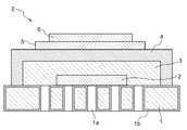
- the metal-supported electrochemical element E includes a metal substrate 1 as a support, an electrode layer 2 formed on the metal substrate 1, and a buffer layer formed on the electrode layer 2. 3 and an electrolyte layer 4 formed on the buffer layer 3.
- the metal-supported electrochemical element E further includes a reaction preventing layer 5 formed on the electrolyte layer 4 and a counter electrode layer 6 formed on the reaction preventing layer 5.
- the counter electrode layer 6 is formed on the electrolyte layer 4, and the reaction preventing layer 5 is formed between the electrolyte layer 4 and the counter electrode layer 6.
- the electrode layer 2 is porous, and the electrolyte layer 4 is dense.
- the density of the buffer layer 3 is larger than the density of the electrode layer 2 and smaller than the density of the electrolyte layer 4.
- the fine density is a ratio of the material constituting the layer to the space, and can be expressed as (1-porosity). Moreover, it is equivalent to the relative density.
- the metal substrate 1 plays a role as a support that supports the electrode layer 2, the buffer layer 3, the electrolyte layer 4, and the like and maintains the strength of the metal-supported electrochemical element E.
- a material excellent in electronic conductivity, heat resistance, oxidation resistance and corrosion resistance is used.
- ferritic stainless steel, austenitic stainless steel, nickel alloy or the like is used.
- an alloy containing chromium is preferably used.
- the metal substrate 1 has a plurality of through holes 1a provided through the front surface and the back surface.
- the through-hole 1a can be provided in the metal substrate 1 by laser processing or the like.
- the through hole 1a has a function of allowing gas to pass from the back surface of the metal substrate 1 to the front surface.
- a porous metal can be used.
- a metal oxide layer 1 b as a diffusion suppression layer is provided on the surface of the metal substrate 1. That is, a diffusion suppression layer is formed between the metal substrate 1 and an electrode layer 2 described later.
- the metal oxide layer 1b is provided not only on the surface exposed to the outside of the metal substrate 1, but also on the contact surface (interface) with the electrode layer 2 and the inner surface of the through hole 1a.
- element interdiffusion between the metal substrate 1 and the electrode layer 2 can be suppressed.
- the metal oxide layer 1b is mainly composed of chromium oxide.
- the metal oxide layer 1b which has a chromium oxide as a main component suppresses that the chromium atom etc.
- the thickness of the metal oxide layer 1b is preferably in the submicron order.
- the average thickness is preferably about 0.3 ⁇ m or more and 0.7 ⁇ m or less.
- the minimum thickness is preferably about 0.1 ⁇ m or more.
- the maximum thickness is preferably about 1.1 ⁇ m or less.
- YSZ yttria stabilized zirconia
- GDC also referred to as gadolinium doped ceria, CGO
- a metal-supported electrochemical element E having excellent long-term durability can be realized.
- the electrode layer 2 is provided in a thin film state on a surface on the front side of the metal substrate 1 and larger than a region where the through hole 1 a is provided.
- the entire region where the through hole 1 a is provided is covered with the electrode layer 2. That is, the through hole 1a is formed inside the region of the metal substrate 1 where the electrode layer 2 is formed. In other words, all the through holes 1 a are provided facing the electrode layer 2.
- a cermet material such as NiO—GDC, Ni—GDC, NiO—YSZ, Ni—YSZ, CuO—CeO 2 , and Cu—CeO 2 can be used.
- GDC, YSZ, and CeO 2 can be referred to as cermet aggregates.
- the electrode layer 2 is preferably formed by a low-temperature baking method (for example, a wet method using a baking process in a low temperature range in which a baking process in a high temperature range higher than 1100 ° C. is not performed), an aerosol deposition method, a thermal spraying method, or the like. .
- a good electrode layer 2 can be obtained without using firing in a high temperature range higher than 1100 ° C., for example. Therefore, it is preferable because the interdiffusion between the metal substrate 1 and the electrode layer 2 can be suppressed without damaging the metal substrate 1 and an electrochemical element having excellent durability can be realized. Furthermore, it is more preferable to use a low-temperature firing method because handling of raw materials becomes easy.
- the electrode layer 2 has a plurality of pores inside and on the surface in order to impart gas permeability. That is, the electrode layer 2 is formed as a porous layer.
- the electrode layer 2 is formed, for example, so that the density thereof is 30% or more and less than 80%.
- As the size of the pores a size suitable for a smooth reaction to proceed during the electrochemical reaction can be appropriately selected.
- the buffer layer 3 is formed in a thin film state on the electrode layer 2 while covering the electrode layer 2.
- the material of the buffer layer 3 include YSZ (yttria stabilized zirconia), SSZ (scandium stabilized zirconia), GDC (gadolinium doped ceria), YDC (yttrium doped ceria), SDC (samarium doped Ceria) or the like can be used.
- ceria-based ceramics are preferably used.
- the buffer layer 3 is preferably formed by a low-temperature baking method (for example, a wet method using a baking process in a low temperature range in which a baking process in a high temperature range higher than 1100 ° C. is not performed), an aerosol deposition method, a thermal spraying method, or the like.
- a low-temperature baking method for example, a wet method using a baking process in a low temperature range in which a baking process in a high temperature range higher than 1100 ° C. is not performed
- an aerosol deposition method for example, an aerosol deposition method, a thermal spraying method, or the like.
- the buffer layer 3 has the following configuration and characteristics.
- the buffer layer 3 is formed so that its density is larger than that of the electrode layer 2 and smaller than that of the electrolyte layer 4.
- the buffer layer 3 has a density of 30% or more and less than 80%
- the buffer layer 3 has a density of 50% or more and less than 98%
- the electrolyte layer 4 has a density of 96% or more.
- Each layer is formed so that the density thereof is larger than that of the electrode layer 2 and smaller than that of the electrolyte layer 4.
- the respective densities (relative densities) of the buffer layer 3, the electrolyte layer 4, and the electrode layer 2 are determined by the respective materials, conditions at the time of formation, and the like.
- the density of the buffer layer 3, the electrolyte layer 4, and the electrode layer 2 to be formed varies depending on various formation conditions such as the particle size, shape and composition of the material powder, and the temperature during firing. That is, by appropriately adjusting these conditions, the density of the buffer layer 3, the electrolyte layer 4, and the electrode layer 2 can be adjusted.
- the buffer layer 3 is formed so that the thickness thereof is within a predetermined range by appropriately setting the form of the material, conditions at the time of formation, and the like. Specifically, the buffer layer 3 is preferably formed to have a thickness of 4 ⁇ m or more, and is preferably formed to have a thickness of 10 ⁇ m or less.
- the buffer layer 3 is continuously connected to alleviate various stresses applied during the manufacture of the device and the operation of the device. As a layer having a buffering effect, it is disposed between the two. Therefore, the buffer layer 3 is formed so that the density is lower than that of the electrolyte layer 4. In addition, the buffer layer 3 is formed so as to have a higher density than the electrode layer 2. As a result, even if the porous electrode layer 2 and the dense electrolyte layer 4 are formed on the metal substrate, the buffer layer 3 absorbs and relaxes various stresses between the layers, thereby supporting the metal support type. It also has the effect of improving the performance, reliability and stability of the electrochemical element E.
- the buffer layer 3 preferably has oxygen ion (oxide ion) conductivity. Further, it is more preferable to have mixed conductivity of oxygen ions (oxide ions) and electrons.
- the buffer layer 3 having these properties is suitable for application to the metal-supported electrochemical device E.
- the buffer layer 3 preferably does not contain a catalytic metal component such as Ni or Cu. This is because when a catalytic metal component such as Ni or Cu is included, it is difficult to obtain the desired buffer layer 3.
- the electrolyte layer 4 is formed in a thin film state on the buffer layer 3 while covering the electrode layer 2 and the buffer layer 3.
- the electrolyte layer 4 is provided over the buffer layer 3 and the metal substrate 1 as shown in FIG. By comprising in this way and joining the electrolyte layer 4 to the metal substrate 1, the whole electrochemical element can be excellent in robustness.
- the electrolyte layer 4 is provided in a region on the front side surface of the metal substrate 1 which is larger than the region in which the through hole 1 a is provided. That is, the through hole 1a is formed inside the region of the metal substrate 1 where the electrolyte layer 4 is formed.
- gas leakage from the electrode layer 2 and the buffer layer 3 can be suppressed around the electrolyte layer 4.
- gas is supplied from the back side of the metal substrate 1 to the electrode layer 2 through the through hole 1a when the SOFC is operated.
- gas leakage can be suppressed without providing another member such as a gasket.
- the entire periphery of the electrode layer 2 is covered with the electrolyte layer 4, but the electrolyte layer 4 may be provided above the electrode layer 2 and the buffer layer 3, and a gasket or the like may be provided around the electrode layer 2.
- Examples of the material of the electrolyte layer 4 include YSZ (yttria stabilized zirconia), SSZ (scandium stabilized zirconia), GDC (gadolinium doped ceria), YDC (yttrium doped ceria), SDC (samarium doped ceria). Etc. can be used. In particular, zirconia ceramics are preferably used. When the electrolyte layer 4 is made of zirconia ceramics, the operating temperature of the SOFC using the metal-supported electrochemical element E can be made higher than that of ceria ceramics.
- the material of the electrolyte layer 4 is a material that can exhibit high electrolyte performance even in a high temperature range of about 650 ° C. or higher, such as YSZ.
- a hydrocarbon-based raw fuel such as LPG
- the heat generated in the SOFC cell stack is highly efficient for reforming the raw fuel gas.
- a SOFC system can be constructed.
- the electrolyte layer 4 is formed by a low-temperature firing method (for example, a wet method using a firing process in a low temperature range in which a firing process is not performed in a high temperature range of 1100 ° C. or higher), an aerosol deposition method, a thermal spraying method, a sputtering method, or a pulse laser deposition method. It is preferable to form by such as.
- a low-temperature firing method for example, a wet method using a firing process in a low temperature range in which a firing process is not performed in a high temperature range of 1100 ° C. or higher
- an aerosol deposition method for example, a wet method using a firing process in a low temperature range in which a firing process is not performed in a high temperature range of 1100 ° C. or higher
- a thermal spraying method for example, a sputtering method, or a pulse laser deposition method.
- a pulse laser deposition method for example, a pulse laser
- a metal-supported electrochemical element E excellent in performance and durability can be realized.
- a low-temperature baking method, an aerosol deposition method, a thermal spraying method, or the like because a low-cost element can be realized.
- the aerosol deposition method because a dense electrolyte layer having a high gas tightness and gas barrier property can be easily obtained in a low temperature range.
- Electrolyte layer 4 is densely configured to shield gas leakage of anode gas and cathode gas and to exhibit high ionic conductivity.
- the density of the electrolyte layer 4 is desirably 96% or more, and more desirably 98% or more.
- the density thereof is preferably 96% or more, and more preferably 98% or more.
- the electrolyte layer 4 is configured in a plurality of layers, it is preferable that at least a part thereof includes a layer (dense electrolyte layer) having a density of 98% or more, and 99% It is more preferable that the above layer (dense electrolyte layer) is included.
- the reaction preventing layer 5 is a layer formed in a thin film shape on the electrolyte layer 4.
- the reaction preventing layer 5 may be made of any material that can prevent the reaction between the components of the electrolyte layer 4 and the counter electrode layer 6.
- a ceria material or the like is used.
- a metal-supported electrochemical element E having excellent performance and durability can be realized.
- a wet method such as printing or spraying, an aerosol deposition method, a thermal spraying method, a sputtering method, a pulse laser deposition method, or the like can be used as appropriate.
- a low-temperature baking method such as printing or spraying, an aerosol deposition method, a thermal spraying method, a sputtering method, a pulse laser deposition method, or the like
- it is more preferable to use a low-temperature firing method because handling of raw materials becomes easy.
- the counter electrode layer 6 is a layer formed in a thin film on the electrolyte layer 4 or the reaction preventing layer 5.
- a material of the counter electrode layer 6 for example, a complex oxide such as LSCF, LSM, or the like can be used.
- the counter electrode layer 6 is formed by appropriately using a method that can be formed at a processing temperature of 1100 ° C. or less, and damage to the metal substrate 1 is suppressed, and element mutual diffusion between the metal substrate 1 and the electrode layer 2 is suppressed. Can be suppressed, and a metal-supported electrochemical element E excellent in performance and durability can be realized.
- a wet method such as printing or spraying, an aerosol deposition method, a thermal spraying method, a sputtering method, a pulse laser deposition method, or the like can be used as appropriate.
- a low-temperature baking method such as printing or spraying, an aerosol deposition method, a thermal spraying method, a sputtering method, a pulse laser deposition method, or the like
- a low-temperature baking method, an aerosol deposition method, a thermal spraying method, or the like because a low-cost element can be realized.
- it is more preferable to use a low-temperature firing method because handling of raw materials becomes easy.
- the metal-supported electrochemical element E can be used as a power generation cell of a solid oxide fuel cell.
- a fuel gas containing hydrogen is supplied from the back surface of the metal substrate 1 to the electrode layer 2 through the through-hole 1a, and air is supplied to the counter electrode layer 6 which is the counter electrode of the electrode layer 2, for example, 600 ° C. or more and 750 Operate at a temperature below °C.
- oxygen O 2 contained in the air reacts with electrons e ⁇ in the counter electrode layer 6 to generate oxygen ions O 2 ⁇ .
- the oxygen ions O 2 ⁇ move through the electrolyte layer 4 to the electrode layer 2.
- the electrode layer 2 hydrogen H 2 contained in the supplied fuel gas reacts with oxygen ions O 2 ⁇ to generate water H 2 O and electrons e ⁇ . Due to the above reaction, an electromotive force is generated between the electrode layer 2 and the counter electrode layer 6.
- the electrode layer 2 functions as an SOFC fuel electrode (anode)
- the counter electrode layer 6 functions as an air electrode (cathode).
- the electrode layer 2 is formed in a thin film state in a region wider than a region where the through hole 1a on the front side surface of the metal substrate 1 is provided.
- the through hole of the metal substrate 1 can be provided by laser processing or the like.
- the electrode layer 2 can be formed by a method such as a low temperature firing method (a wet method in which a firing treatment is performed in a low temperature region of 1100 ° C. or lower), an aerosol deposition method, or a thermal spray method. Regardless of which method is used, it is desirable to carry out at a temperature of 1100 ° C. or lower in order to suppress the deterioration of the metal substrate 1.
- the electrode layer forming step is performed by a low temperature firing method, specifically, it is performed as in the following example.
- a material paste is prepared by mixing the material powder of the electrode layer 2 and a solvent, applied to the front side surface of the metal substrate 1, and baked at 800 ° C to 1100 ° C.
- the metal oxide layer 1b (diffusion suppression layer) is formed on the surface of the metal substrate 1.
- the firing step includes a firing step in which the firing atmosphere is an atmospheric condition with a low oxygen partial pressure, a high-quality metal oxide layer 1b (diffusion restraint) that has a high element interdiffusion suppression effect and a low resistance value. Layer) is preferable.
- a separate diffusion suppression layer forming step may be included, including the case where the electrode layer forming step is a method without firing (for example, an aerosol deposition method). In any case, it is desirable to carry out at a processing temperature of 1100 ° C. or less that can suppress damage to the metal substrate 1.
- the buffer layer 3 is formed in a thin film state on the electrode layer 2 so as to cover the electrode layer 2.
- the buffer layer 3 can be formed by a method such as a low temperature firing method (wet method in which a firing treatment is performed in a low temperature region of 1100 ° C. or lower), an aerosol deposition method, or a thermal spray method. Regardless of which method is used, it is desirable to carry out at a temperature of 1100 ° C. or lower in order to suppress the deterioration of the metal substrate 1.
- the buffer layer forming step is performed by a low temperature baking method, specifically, it is performed as in the following example.
- the material powder of the buffer layer 3 and the solvent are mixed to prepare a material paste, which is applied onto the electrode layer 2 and baked at 800 ° C. to 1100 ° C.
- the electrolyte layer 4 is formed on the buffer layer 3 in a thin film state while covering the electrode layer 2 and the buffer layer 3.
- the electrolyte layer 4 is formed by a low temperature firing method (wet method in which a firing process is performed at a low temperature of 1100 ° C. or lower), an aerosol deposition method, a thermal spraying method, a sputtering method, a pulse laser deposition method, or the like. The method can be used. Regardless of which method is used, it is desirable to carry out at a temperature of 1100 ° C. or lower in order to suppress the deterioration of the metal substrate 1.
- the electrolyte layer formation step by an aerosol deposition method.
- the material powder of the electrolyte layer 4 is aerosolized with a carrier gas, and the aerosol is sprayed toward the buffer layer 3 of the metal substrate 1 to form the electrolyte layer 4.
- reaction prevention layer formation step the reaction preventing layer 5 is formed on the electrolyte layer 4 in a thin film state.
- the reaction preventing layer 5 can be formed by a method such as a low temperature baking method, an aerosol deposition method, a thermal spraying method, a sputtering method, or a pulse laser deposition method. Regardless of which method is used, it is desirable to carry out at a temperature of 1100 ° C. or lower in order to suppress the deterioration of the metal substrate 1.
- the counter electrode layer 6 is formed on the reaction preventing layer 5 in a thin film state.
- the counter electrode layer 6 can be formed by a method such as a low-temperature baking method, an aerosol deposition method, a thermal spraying method, a sputtering method, or a pulsed laser deposition method. Regardless of which method is used, it is desirable to carry out at a temperature of 1100 ° C. or lower in order to suppress the deterioration of the metal substrate 1.
- the metal-supported electrochemical element E can be manufactured. It is possible to omit the reaction preventing layer forming step, to add another layer forming step, or to stack a plurality of the same type of layers. It is desirable to carry out at the following temperature.
- both the electrode layer 2 and the electrolyte layer 4 are provided in a region that is a surface on the front side of the metal substrate 1 and that is larger than the region in which the through hole 1 a is provided. .
- the entire region where the through hole 1 a is provided is covered with the electrode layer 2 and the electrolyte layer 4. That is, the through hole 1a is formed inside the region where the electrode layer 2 is formed on the metal substrate 1 and inside the region where the electrolyte layer 4 is formed. In other words, all the through holes 1 a are provided facing the electrode layer 2. It is also possible to change this to the configuration shown in FIG.
- the electrode layer 2 is provided in a region smaller than the region in which the through hole 1a is provided.
- the buffer layer 3 and the electrolyte layer 4 are provided in a region larger than the region where the through hole 1a is provided.
- the entire region where the through hole 1 a is provided is covered with the buffer layer 3 and the electrolyte layer 4. That is, the through-hole 1a is provided inside and outside the region where the electrode layer 2 is formed.
- the through hole 1a is provided inside the region where the electrolyte layer 4 is formed. In other words, the through hole 1 a is provided so as to face both the electrode layer 2 and the buffer layer 3.
- the configuration shown in FIG. 3 is also possible.
- the electrode layer 2 and the buffer layer 3 are provided in a region smaller than the region in which the through hole 1a is provided.
- the electrolyte layer 4 is provided in a larger area than the area where the through hole 1a is provided.
- the entire region where the through hole 1 a is provided is covered with the electrolyte layer 4. That is, the through-hole 1a is provided inside and outside the region where the electrode layer 2 is formed.
- the through hole 1a is provided inside and outside the region where the buffer layer 3 is formed.
- the through hole 1a is provided inside the region where the electrolyte layer 4 is formed. In other words, the through hole 1 a is provided facing the electrode layer 2, the buffer layer 3, and the electrolyte layer 4.
- the configuration shown in FIG. 4 is also possible.
- the electrode layer 2 and the buffer layer 3 are provided in a region smaller than the region in which the through hole 1a is provided.
- the buffer layer 3 is provided in a region where the electrode layer 2 is provided.
- the electrolyte layer 4 is provided in a larger area than the area where the through hole 1a is provided.
- the entire region where the through hole 1 a is provided is covered with the electrolyte layer 4. That is, the through-hole 1a is provided inside and outside the region where the electrode layer 2 is formed.
- the through hole 1a is provided inside the region where the electrolyte layer 4 is formed. In other words, the through hole 1 a is provided facing the electrode layer 2 and the electrolyte layer 4.
- the metal-supported electrochemical element E is used in a solid oxide fuel cell, but the metal-supported electrochemical element E is a solid oxide electrolytic cell or an oxygen sensor using a solid oxide. Etc. can also be used.
- a cermet material such as NiO—GDC, Ni—GDC, NiO—YSZ, Ni—YSZ, CuO—CeO 2 , Cu—CeO 2 is used as the material of the electrode layer 2 , and the counter electrode layer 6
- a composite oxide such as LSCF or LSM was used as the material.
- hydrogen gas was supplied to the electrode layer 2 as a fuel electrode
- air was supplied to the counter electrode layer 6 as an air electrode
- the metal-supported electrochemical element E was used as a solid oxide fuel cell.
- the metal-supported electrochemical element E can be configured such that the electrode layer 2 can be an air electrode and the counter electrode layer 6 can be a fuel electrode.
- a composite oxide such as LSCF or LSM is used as the material of the electrode layer 2
- NiO—GDC, Ni—GDC, NiO—YSZ, Ni—YSZ, CuO—CeO 2 , Cu is used as the material of the counter electrode layer 6, for example.
- a cermet material such as CeO 2 .
- air is supplied to the electrode layer 2 to form an air electrode
- hydrogen gas is supplied to the counter electrode layer 6 to form a fuel electrode
- the metal-supported electrochemical element is formed.
- E can be used as a solid oxide fuel cell.
- a metal substrate 1 was prepared by providing a plurality of through-holes 1a by laser processing in a region having a radius of 2.5 mm from the center of a circular craft 22APU metal plate having a thickness of 0.3 mm and a diameter of 25 mm. At this time, the through hole was provided by laser processing so that the diameter of the through hole 1a on the surface of the metal substrate 1 was about 10 to 15 ⁇ m.
- the electrode layer 2 was laminated in a region having a radius of 3 mm from the center of the metal substrate 1.
- the electrode layer 2 was formed by screen printing.
- the metal substrate 1 on which the electrode layer 2 was laminated was baked at 850 ° C. (electrode layer formation step, diffusion suppression layer formation step).
- the amount of He leak of the metal substrate 1 in a state where the electrode layer 2 was laminated was an amount exceeding 50 mL / min ⁇ cm 2 under a pressure of 0.2 MPa. From this, it can be seen that the electrode layer 2 is formed as a porous layer having a low density and a low gas barrier property.
- the buffer layer 3 was laminated
- the metal substrate 1 on which the buffer layer 3 was laminated was baked at 1050 ° C. (buffer layer forming step).
- the thickness of the electrode layer 2 obtained by the above steps was about 10 ⁇ m, and the thickness of the buffer layer 3 was about 8 ⁇ m. Further, the amount of He leak of the metal substrate 1 in the state where the electrode layer 2 and the buffer layer 3 were laminated in this way was 13.5 mL / min ⁇ cm 2 under a pressure of 0.2 MPa.
- 8YSZ (yttria stabilized zirconia) powder having a mode diameter of about 0.7 ⁇ m was aerosolized with dry air at a flow rate of 6 L / min. Aerosol was introduced into a chamber having a pressure of 190 Pa, and sprayed on the buffer layer 3 of the metal substrate 1 in a range of 15 mm ⁇ 15 mm so as to cover the buffer layer 3, thereby laminating the electrolyte layer 4. At that time, the metal substrate 1 was not heated and sprayed at room temperature (electrolyte layer forming step). Thus, a metal-supported electrochemical element E was formed.
- the thickness of the electrolyte layer 4 obtained by the above steps was about 5 ⁇ m.
- the amount of He leak of the metal substrate 1 in the state where the electrode layer 2, the buffer layer 3 and the electrolyte layer 4 were laminated was measured under a pressure of 0.2 MPa, the amount of He leak was a detection lower limit (1.0 mL / Min.cm 2 ). That is, the amount of He leak in the state where the electrolyte layer 4 is laminated is significantly smaller than the amount of He leak in the state where up to the buffer layer 3 is laminated, which is below the detection limit. Therefore, it was confirmed that the formed electrolyte layer 4 was dense and high in quality with high gas barrier performance.
- a reaction preventing layer 5 was formed on the electrolyte layer 4 of the metal-supported electrochemical device E by screen printing.
- reaction preventing layer forming step After the metal-supported electrochemical element E on which the reaction preventing layer 5 was formed was baked at 1000 ° C. (reaction preventing layer forming step).
- the metal-supported electrochemical element E on which the counter electrode layer 6 was formed was fired at 900 ° C. (counter electrode layer forming step) to obtain the metal-supported electrochemical element E.
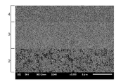
- FIG. 5 shows an electron micrograph of a cross section of the metal-supported electrochemical element E thus obtained.
- the electrode layer 2 has a large number of black voids / holes and has a relatively small density. From the image processing data of FIG. 5, it is estimated that the density of the electrode layer 2 is about 68%.
- the electrolyte layer 4 is very dense with almost no black voids or holes. From the image processing data of FIG. 5, it is estimated that the density of the electrolyte layer 4 is about 99% or more.
- the density of the buffer layer 3 is smaller than that of the electrolyte layer 4 and larger than that of the electrode layer 2.
- the density of the buffer layer 3 is estimated to be about 92%. Moreover, when the density of the buffer layer 3 obtained as described above was calculated from the result of measuring the X-ray reflectivity, it was calculated to be 92%. That is, from the above results, it was confirmed that the density of the buffer layer 3 is larger than the density of the electrode layer 2 and smaller than the density of the electrolyte layer 4.
- the firing temperature in the buffer layer forming step was changed to 1000 ° C., and the other steps were the same as in prototype 1 to obtain metal-supported electrochemical element E.
- the thickness of the electrode layer 2 of the obtained sample was about 10 ⁇ m
- the thickness of the buffer layer 3 was about 7 ⁇ m
- the thickness of the electrolyte layer 4 was about 4 ⁇ m.
- the amount of He leak of the metal substrate 1 in a state where the buffer layer 3 was laminated was 7.5 mL / min ⁇ cm 2 under a pressure of 0.2 MPa. Further, the He leak amount of the metal substrate 1 in the state where the electrolyte layer 4 was laminated was less than the detection limit of 1.0 mL / min ⁇ cm 2 under a pressure of 0.2 MPa. Similar to prototype 1, the amount of He leak in the state where the electrolyte layer 4 is laminated is significantly smaller than the amount of He leak in the state where the buffer layer 3 is laminated, which is below the detection limit. . Therefore, it was confirmed that the formed electrolyte layer 4 was dense and high in quality with high gas barrier performance.
- FIG. 6 shows an electron micrograph of a cross section of the metal-supported electrochemical element E thus obtained.
- the electrode layer 2 has a large number of black voids / holes and has a relatively small density. From the image processing data of FIG. 6, the density of the electrode layer 2 is estimated to be about 79%.
- the electrolyte layer 4 is very dense with almost no black voids or holes. From the image processing data of FIG. 6, it is estimated that the density of the electrolyte layer 4 is about 97% or more.
- the density of the buffer layer 3 is slightly reduced. From the image processing data of FIG. 6, it is estimated that the density of the buffer layer 3 is about 95%. That is, from the above results, it was confirmed that the density of the buffer layer 3 is larger than the density of the electrode layer 2 and smaller than the density of the electrolyte layer 4.
- the firing temperature in the buffer layer forming step was changed to 950 ° C., and the other steps were the same as in prototype 1 to obtain metal-supported electrochemical element E.
- the thickness of the electrode layer 2 of the obtained sample was about 13 ⁇ m
- the thickness of the buffer layer 3 was about 7 ⁇ m
- the thickness of the electrolyte layer 4 was about 4 ⁇ m.
- the amount of He leak of the metal substrate 1 in a state where the buffer layer 3 was laminated was 26.5 mL / min ⁇ cm 2 under a pressure of 0.2 MPa. Further, the He leak amount of the metal substrate 1 in the state where the electrolyte layer 4 was laminated was less than the detection limit of 1.0 mL / min ⁇ cm 2 under a pressure of 0.2 MPa. Similar to prototype 1, the amount of He leak in the state where the electrolyte layer 4 is laminated is significantly smaller than the amount of He leak in the state where the buffer layer 3 is laminated, which is below the detection limit. . Therefore, it was confirmed that the formed electrolyte layer 4 was dense and high in quality with high gas barrier performance.
- Metal substrate 1a Through hole 1b: Metal oxide layer (diffusion suppression layer) 2: Electrode layer 3: Buffer layer 4: Electrolyte layer 5: Reaction prevention layer 6: Counter electrode layer E: Metal-supported electrochemical device
Abstract
Description
前記緩衝層の緻密度が前記電極層よりも大きく、かつ前記電解質層の緻密度よりも小さく、
前記電極層形成ステップと前記緩衝層形成ステップと前記電解質層形成ステップとが1100℃以下で行われる点にある。 In order to achieve the above object, the method for producing a metal-supported electrochemical device according to the present invention includes an electrode layer forming step of forming a porous electrode layer on a metal substrate as a support, and the electrode A buffer layer forming step for forming a buffer layer on the layer; and an electrolyte layer forming step for forming a dense electrolyte layer on the buffer layer,
The density of the buffer layer is greater than the electrode layer and less than the density of the electrolyte layer;
The electrode layer forming step, the buffer layer forming step, and the electrolyte layer forming step are performed at 1100 ° C. or less.
以下、図1および図2を参照しながら、金属支持型電気化学素子E、固体酸化物形燃料電池(Solid Oxide Fuel Cell:SOFC)、および金属支持型電気化学素子Eの製造方法について説明する。金属支持型電気化学素子Eは、例えば、水素を含む燃料ガスと空気の供給を受けて発電する固体酸化物形燃料電池の構成要素として用いられる。なお以下、層の位置関係などを表す際、例えば緩衝層3から見て電解質層4の側を「上」または「上側」、電極層2の側を「下」または「下側」という場合がある。また、金属基板1における電極層2が形成されている側の面を「表側」、反対側の面を「裏側」という場合がある。 (First embodiment)
Hereinafter, with reference to FIG. 1 and FIG. 2, a method for producing a metal-supported electrochemical element E, a solid oxide fuel cell (SOFC), and a metal-supported electrochemical element E will be described. The metal-supported electrochemical element E is used, for example, as a constituent element of a solid oxide fuel cell that generates electric power by receiving supply of a fuel gas containing hydrogen and air. Hereinafter, when expressing the positional relationship of the layers, for example, the side of the electrolyte layer 4 as viewed from the
金属支持型電気化学素子Eは、図1に示される通り、支持体としての金属基板1と、金属基板1の上に形成された電極層2と、電極層2の上に形成された緩衝層3と、緩衝層3の上に形成された電解質層4とを少なくとも有する。そして金属支持型電気化学素子Eは、更に、電解質層4の上に形成された反応防止層5と、反応防止層5の上に形成された対極電極層6とを有する。対極電極層6は電解質層4の上に形成され、反応防止層5は電解質層4と対極電極層6との間に形成されている。電極層2は多孔質であり、電解質層4は緻密である。そして緩衝層3の緻密度は、電極層2の緻密度よりも大きく、電解質層4の緻密度よりも小さい。なお緻密度とは、層を構成する材料の空間に占める割合であり、(1-空孔率)と表すことができる。また、相対密度と同等である。 (Metal-supported electrochemical device)
As shown in FIG. 1, the metal-supported electrochemical element E includes a
金属基板1は、電極層2、緩衝層3および電解質層4等を支持して金属支持型電気化学素子Eの強度を保つ、支持体としての役割を担う。金属基板1の材料としては、電子伝導性、耐熱性、耐酸化性および耐腐食性に優れた材料が用いられる。例えば、フェライト系ステンレス、オーステナイト系ステンレス、ニッケル合金などが用いられる。特に、クロムを含む合金が好適に用いられる。 (Metal substrate)
The
また、最大厚さが約1.1μm以下であることが好ましい。 A
The maximum thickness is preferably about 1.1 μm or less.
電極層2は、図1に示すように、金属基板1の表側の面であって貫通孔1aが設けられた領域より大きな領域に、薄膜の状態で設けられる。貫通孔1aが設けられた領域の全体が、電極層2に覆われている。つまり、貫通孔1aは金属基板1における電極層2が形成された領域の内側に形成されている。換言すれば、全ての貫通孔1aが電極層2に面して設けられている。 (Electrode layer)
As shown in FIG. 1, the
すなわち電極層2は、多孔質な層として形成される。電極層2は、例えば、その緻密度が30%以上80%未満となるように形成される。細孔のサイズは、電気化学反応を行う際に円滑な反応が進行するのに適したサイズを適宜選ぶことができる。 The
That is, the
緩衝層3は、図1に示すように、電極層2を覆った状態で、電極層2の上に薄膜の状態で形成される。緩衝層3の材料としては、例えば、YSZ(イットリア安定化ジルコニア)、SSZ(スカンジウム安定化ジルコニア)やGDC(ガドリウム・ドープ・セリア)、YDC(イットリウム・ドープ・セリア)、SDC(サマリウム・ドープ・セリア)等を用いることができる。特にセリア系のセラミックスが好適に用いられる。 (Buffer layer)
As shown in FIG. 1, the
電解質層4は、図1に示すように、電極層2および緩衝層3を覆った状態で、緩衝層3の上に薄膜の状態で形成される。詳しくは電解質層4は、図1に示すように、緩衝層3の上と金属基板1の上とにわたって(跨って)設けられる。このように構成し、電解質層4を金属基板1に接合することで、電気化学素子全体として堅牢性に優れたものとすることができる。 (Electrolyte layer)
As shown in FIG. 1, the electrolyte layer 4 is formed in a thin film state on the
反応防止層5は、電解質層4の上に薄膜状に形成された層である。反応防止層5の材料としては、電解質層4の成分と対極電極層6の成分との間の反応を防止できる材料であれば良い。例えばセリア系材料等が用いられる。反応防止層5を電解質層4と対極電極層6との間に導入することにより、対極電極層6の構成材料と電解質層4の構成材料との反応が効果的に抑制され、金属支持型電気化学素子Eの性能の長期安定性を向上できる。反応防止層5の形成は、1100℃以下の処理温度で形成できる方法を適宜用いて行うと、金属基板1の損傷を抑制し、また、金属基板1と電極層2との元素相互拡散を抑制でき、性能・耐久性に優れた金属支持型電気化学素子Eを実現できるので好ましい。例えば、印刷やスプレー等による湿式法(低温焼成法)、エアロゾルデポジション法、溶射法、スパッタリング法、パルスレーザーデポジション法などを適宜用いて行うことができる。特に、低温焼成法やエアロゾルデポジション法や溶射法などを用いると低コストな素子が実現できるので好ましい。更に、低温焼成法を用いると、原材料のハンドリングが容易になるので更に好ましい。 (Anti-reaction layer)
The
対極電極層6は、電解質層4もしくは反応防止層5の上に薄膜状に形成された層である。対極電極層6の材料としては、例えば、LSCF、LSM等の複合酸化物を用いることができる。なお、対極電極層6の形成は、1100℃以下の処理温度で形成できる方法を適宜用いて行うと、金属基板1の損傷を抑制し、また、金属基板1と電極層2との元素相互拡散を抑制でき、性能・耐久性に優れた金属支持型電気化学素子Eを実現できるので好ましい。例えば、印刷やスプレー等による湿式法(低温焼成法)、エアロゾルデポジション法、溶射法、スパッタリング法、パルスレーザーデポジション法などを適宜用いて行うことができる。特に、低温焼成法やエアロゾルデポジション法や溶射法などを用いると低コストな素子が実現できるので好ましい。更に、低温焼成法を用いると、原材料のハンドリングが容易になるので更に好ましい。 (Counter electrode layer)
The counter electrode layer 6 is a layer formed in a thin film on the electrolyte layer 4 or the
以上のように金属支持型電気化学素子Eを構成することで、金属支持型電気化学素子Eを固体酸化物形燃料電池の発電セルとして用いることができる。例えば、金属基板1の裏側の面から貫通孔1aを通じて水素を含む燃料ガスを電極層2へ供給し、電極層2の対極となる対極電極層6へ空気を供給し、例えば、600℃以上750℃以下の温度で作動させる。そうすると、対極電極層6において空気に含まれる酸素O2が電子e-と反応して酸素イオンO2-が生成される。その酸素イオンO2-が電解質層4を通って電極層2へ移動する。電極層2においては、供給された燃料ガスに含まれる水素H2が酸素イオンO2-と反応し、水H2Oと電子e-が生成される。以上の反応により、電極層2と対極電極層6との間に起電力が発生する。この場合、電極層2はSOFCの燃料極(アノード)として機能し、対極電極層6は空気極(カソード)として機能する。 (Solid oxide fuel cell)
By configuring the metal-supported electrochemical element E as described above, the metal-supported electrochemical element E can be used as a power generation cell of a solid oxide fuel cell. For example, a fuel gas containing hydrogen is supplied from the back surface of the
次に、金属支持型電気化学素子Eの製造方法について説明する。 (Method for producing metal-supported electrochemical device)
Next, the manufacturing method of the metal support type electrochemical element E is demonstrated.
電極層形成ステップでは、金属基板1の表側の面の貫通孔1aが設けられた領域より広い領域に電極層2が薄膜の状態で形成される。金属基板1の貫通孔はレーザー加工等によって設けることができる。電極層2の形成は、上述したように、低温焼成法(1100℃以下の低温域での焼成処理を行う湿式法)、エアロゾルデポジション法、溶射法などの方法を用いることができる。いずれの方法を用いる場合であっても、金属基板1の劣化を抑制するため、1100℃以下の温度で行うことが望ましい。 (Electrode layer forming step)
In the electrode layer forming step, the
まず電極層2の材料粉末と溶媒とを混合して材料ペーストを作成し、金属基板1の表側の面に塗布し、800℃~1100℃で焼成する。 When the electrode layer forming step is performed by a low temperature firing method, specifically, it is performed as in the following example.
First, a material paste is prepared by mixing the material powder of the
上述した電極層形成ステップにおける焼成工程時に、金属基板1の表面に金属酸化物層1b(拡散抑制層)が形成される。なお、上記焼成工程に、焼成雰囲気を酸素分圧が低い雰囲気条件とする焼成工程が含まれていると元素の相互拡散抑制効果が高く、抵抗値の低い良質な金属酸化物層1b(拡散抑制層)が形成されるので好ましい。電極層形成ステップを、焼成を行わない方法(例えば、エアロゾルデポジション法など)とする場合を含め、別途の拡散抑制層形成ステップを含めても良い。いずれにおいても、金属基板1の損傷を抑制可能な1100℃以下の処理温度で実施することが望ましい。 (Diffusion suppression layer formation step)
During the firing process in the electrode layer forming step described above, the
緩衝層形成ステップでは、電極層2を覆う形態で、電極層2の上に緩衝層3が薄膜の状態で形成される。緩衝層3の形成は、上述したように、低温焼成法(1100℃以下の低温域での焼成処理を行う湿式法)、エアロゾルデポジション法、溶射法などの方法を用いることができる。いずれの方法を用いる場合であっても、金属基板1の劣化を抑制するため、1100℃以下の温度で行うことが望ましい。 (Buffer layer formation step)
In the buffer layer forming step, the
まず緩衝層3の材料粉末と溶媒とを混合して材料ペーストを作成し、電極層2の上に塗布し、800℃~1100℃で焼成する。 When the buffer layer forming step is performed by a low temperature baking method, specifically, it is performed as in the following example.
First, the material powder of the
電解質層形成ステップでは、電極層2および緩衝層3を覆った状態で、電解質層4が緩衝層3の上に薄膜の状態で形成される。電解質層4の形成は、上述したように、低温焼成法(1100℃以下の低温域での焼成処理を行う湿式法)、エアロゾルデポジション法、溶射法、スパッタリング法、パルスレーザーデポジション法などの方法を用いることができる。いずれの方法を用いる場合であっても、金属基板1の劣化を抑制するため、1100℃以下の温度で行うことが望ましい。 (Electrolyte layer forming step)
In the electrolyte layer forming step, the electrolyte layer 4 is formed on the
反応防止層形成ステップでは、反応防止層5が電解質層4の上に薄膜の状態で形成される。反応防止層5の形成は、上述したように、低温焼成法、エアロゾルデポジション法、溶射法、スパッタリング法、パルスレーザーデポジション法などの方法を用いることができる。いずれの方法を用いる場合であっても、金属基板1の劣化を抑制するため、1100℃以下の温度で行うことが望ましい。 (Reaction prevention layer formation step)
In the reaction preventing layer forming step, the
対極電極層形成ステップでは、対極電極層6が反応防止層5の上に薄膜の状態で形成される。対極電極層6の形成は、上述したように、低温焼成法、エアロゾルデポジション法、溶射法、スパッタリング法、パルスレーザーデポジション法などの方法を用いることができる。いずれの方法を用いる場合であっても、金属基板1の劣化を抑制するため、1100℃以下の温度で行うことが望ましい。 (Counter electrode layer formation step)
In the counter electrode layer forming step, the counter electrode layer 6 is formed on the
上述した第1実施形態では、図1に示すように、電極層2および電解質層4の両方が、金属基板1の表側の面であって貫通孔1aが設けられた領域より大きな領域に設けられる。
貫通孔1aが設けられた領域の全体が、電極層2および電解質層4によって覆われている。
つまり貫通孔1aは、金属基板1における電極層2が形成された領域の内側であって、かつ電解質層4が形成された領域の内側に形成される。換言すれば、全ての貫通孔1aが電極層2に面して設けられている。これを変更して、図2に示す構成とすることも可能である。 (Second Embodiment)
In the first embodiment described above, as shown in FIG. 1, both the
The entire region where the through
That is, the through
また図3に示す構成も可能である。図3に示す構成では、電極層2および緩衝層3が、貫通孔1aが設けられた領域より小さな領域に設けられる。電解質層4が、貫通孔1aが設けられた領域より大きな領域に設けられる。貫通孔1aが設けられた領域の全体が、電解質層4によって覆われている。つまり貫通孔1aは、電極層2が形成された領域の内側と外側とに設けられる。貫通孔1aは、緩衝層3が形成された領域の内側と外側とに設けられる。また貫通孔1aは電解質層4が形成された領域の内側に設けられる。換言すれば、貫通孔1aは電極層2と緩衝層3と電解質層4とに面して設けられている。 (Third embodiment)
The configuration shown in FIG. 3 is also possible. In the configuration shown in FIG. 3, the
つまり貫通孔1aは、電極層2が形成された領域の内側と外側とに設けられる。また貫通孔1aは電解質層4が形成された領域の内側に設けられる。換言すれば、貫通孔1aは電極層2と電解質層4とに面して設けられている。 The configuration shown in FIG. 4 is also possible. In the configuration shown in FIG. 4, the
That is, the through-
上記の実施形態では、金属支持型電気化学素子Eを固体酸化物形燃料電池に用いたが、金属支持型電気化学素子Eは、固体酸化物形電解セルや、固体酸化物を利用した酸素センサ等に利用することもできる。 (Fourth embodiment)
In the above embodiment, the metal-supported electrochemical element E is used in a solid oxide fuel cell, but the metal-supported electrochemical element E is a solid oxide electrolytic cell or an oxygen sensor using a solid oxide. Etc. can also be used.
上記の実施形態では、電極層2の材料として例えばNiO-GDC、Ni-GDC、NiO-YSZ、Ni-YSZ、CuO-CeO2、Cu-CeO2などのサーメット材を用い、対極電極層6の材料として例えばLSCF、LSM等の複合酸化物を用いた。そして電極層2に水素ガスを供給して燃料極とし、対極電極層6に空気を供給して空気極とし、金属支持型電気化学素子Eを固体酸化物型燃料電池セルとして用いた。これを変更して、電極層2を空気極とし、対極電極層6を燃料極とすることが可能なように、金属支持型電気化学素子Eを構成することも可能である。すなわち、電極層2の材料として例えばLSCF、LSM等の複合酸化物を用い、対極電極層6の材料として例えばNiO-GDC、Ni-GDC、NiO-YSZ、Ni-YSZ、CuO-CeO2、Cu-CeO2などのサーメット材を用いる。このように構成した金属支持型電気化学素子Eであれば、電極層2に空気を供給して空気極とし、対極電極層6に水素ガスを供給して燃料極とし、金属支持型電気化学素子Eを固体酸化物型燃料電池セルとして用いることができる。 (Fifth embodiment)
In the above embodiment, a cermet material such as NiO—GDC, Ni—GDC, NiO—YSZ, Ni—YSZ, CuO—CeO 2 , Cu—CeO 2 is used as the material of the electrode layer 2 , and the counter electrode layer 6 For example, a composite oxide such as LSCF or LSM was used as the material. Then, hydrogen gas was supplied to the
(試作品1:実施例)
厚さ0.3mm、直径25mmの円形のcrofer22APUの金属板に対して、中心から半径2.5mmの領域にレーザー加工により貫通孔1aを複数設けて、金属基板1を作成した。なお、この時、金属基板1の表面の貫通孔1aの直径が10~15μm程度となるようにレーザー加工により貫通孔を設けた。 Hereinafter, the results of making various prototypes of the metal-supported electrochemical element E under various conditions and performing various measurements will be described.
(Prototype 1: Example)
A
緩衝層形成ステップでの焼成温度を1000℃に変更し、その他は試作品1と同様のステップにて金属支持型電気化学素子Eを得た。得られたサンプルの電極層2の厚さは約10μmであり、緩衝層3の厚さは約7μmであり、電解質層4の厚さは約4μmであった。 (Prototype 2: Example)
The firing temperature in the buffer layer forming step was changed to 1000 ° C., and the other steps were the same as in
緩衝層形成ステップでの焼成温度を950℃に変更し、その他は試作品1と同様のステップにて金属支持型電気化学素子Eを得た。得られたサンプルの電極層2の厚さは約13μmであり、緩衝層3の厚さは約7μmであり、電解質層4の厚さは約4μmであった。 (Prototype 3: Example)
The firing temperature in the buffer layer forming step was changed to 950 ° C., and the other steps were the same as in
1a :貫通孔
1b :金属酸化物層(拡散抑制層)
2 :電極層
3 :緩衝層
4 :電解質層
5 :反応防止層
6 :対極電極層
E :金属支持型電気化学素子 1:
2: Electrode layer 3: Buffer layer 4: Electrolyte layer 5: Reaction prevention layer 6: Counter electrode layer E: Metal-supported electrochemical device
Claims (16)
- 支持体としての金属基板と、前記金属基板の上に形成された電極層と、前記電極層の上に形成された緩衝層と、前記緩衝層の上に形成された電解質層とを少なくとも有し、前記電極層が多孔質であり、前記電解質層が緻密であり、前記緩衝層の緻密度が前記電極層の緻密度よりも大きく、かつ前記電解質層の緻密度よりも小さい金属支持型電気化学素子。 At least a metal substrate as a support, an electrode layer formed on the metal substrate, a buffer layer formed on the electrode layer, and an electrolyte layer formed on the buffer layer The electrode layer is porous, the electrolyte layer is dense, the density of the buffer layer is larger than the density of the electrode layer, and smaller than the density of the electrolyte layer. element.
- 前記緩衝層がセリア系材料を含む請求項1に記載の金属支持型電気化学素子。 The metal-supported electrochemical device according to claim 1, wherein the buffer layer contains a ceria-based material.
- 前記電解質層が安定化ジルコニアを含む請求項1または2に記載の金属支持型電気化学素子。 The metal-supported electrochemical device according to claim 1 or 2, wherein the electrolyte layer contains stabilized zirconia.
- 前記緩衝層の厚さが4μm以上である請求項1~3のいずれか一項に記載の金属支持型電気化学素子。 The metal-supported electrochemical device according to any one of claims 1 to 3, wherein the buffer layer has a thickness of 4 µm or more.
- 前記緩衝層の厚さが10μm以下である請求項1~3のいずれか一項に記載の金属支持型電気化学素子。 The metal-supported electrochemical element according to any one of claims 1 to 3, wherein the buffer layer has a thickness of 10 µm or less.
- 前記緩衝層の緻密度が50%以上98%未満である請求項1~5のいずれか一項に記載の金属支持型電気化学素子。 The metal-supported electrochemical device according to any one of claims 1 to 5, wherein the density of the buffer layer is 50% or more and less than 98%.
- 前記電解質層の一部に、緻密度が98%以上である緻密電解質層が含まれている請求項1~6のいずれか一項に記載の金属支持型電気化学素子。 The metal-supported electrochemical device according to any one of claims 1 to 6, wherein a dense electrolyte layer having a density of 98% or more is included in a part of the electrolyte layer.
- 前記金属基板から前記電極層へのCrの拡散を抑制する拡散抑制層を有する請求項1~7のいずれか一項に記載の金属支持型電気化学素子。 The metal-supported electrochemical device according to any one of claims 1 to 7, further comprising a diffusion suppressing layer that suppresses diffusion of Cr from the metal substrate to the electrode layer.
- 前記拡散抑制層が、前記金属基板の表面に形成された金属酸化物層である請求項8に記載の金属支持型電気化学素子。 The metal-supported electrochemical device according to claim 8, wherein the diffusion suppressing layer is a metal oxide layer formed on a surface of the metal substrate.
- 前記金属基板が複数の貫通孔を有する請求項1~9のいずれか一項に記載の金属支持型電気化学素子。 The metal-supported electrochemical element according to any one of claims 1 to 9, wherein the metal substrate has a plurality of through holes.
- 前記貫通孔は前記金属基板における前記電解質層が形成された領域の内側に形成されている請求項10に記載の金属支持型電気化学素子。 The metal-supported electrochemical device according to claim 10, wherein the through hole is formed inside a region of the metal substrate where the electrolyte layer is formed.
- 前記貫通孔は前記金属基板における前記電極層が形成された領域の内側に形成されている請求項10または11に記載の金属支持型電気化学素子。 12. The metal-supported electrochemical device according to claim 10, wherein the through hole is formed inside a region of the metal substrate where the electrode layer is formed.
- 前記電解質層の上に形成された、前記電極層の対極となる対極電極層を有する請求項1~12のいずれか一項に記載の金属支持型電気化学素子。 The metal-supported electrochemical device according to any one of claims 1 to 12, further comprising a counter electrode layer formed on the electrolyte layer and serving as a counter electrode of the electrode layer.
- 前記電解質層と前記対極電極層との間に形成された反応防止層を有する請求項13に記載の金属支持型電気化学素子。 The metal-supported electrochemical device according to claim 13, further comprising a reaction preventing layer formed between the electrolyte layer and the counter electrode layer.
- 請求項1~14のいずれか一項に記載の金属支持型電気化学素子を有し、定格運転時に600℃以上750℃以下の温度域で運転可能な固体酸化物形燃料電池。 A solid oxide fuel cell comprising the metal-supported electrochemical device according to any one of claims 1 to 14, and capable of operating in a temperature range of 600 ° C or higher and 750 ° C or lower during rated operation.
- 金属支持型電気化学素子の製造方法であって、支持体としての金属基板の上に多孔質な電極層を形成する電極層形成ステップと、前記電極層の上に緩衝層を形成する緩衝層形成ステップと、前記緩衝層の上に緻密な電解質層を形成する電解質層形成ステップとを有し、
前記緩衝層の緻密度が前記電極層よりも大きく、かつ前記電解質層の緻密度よりも小さく、
前記電極層形成ステップと前記緩衝層形成ステップと前記電解質層形成ステップとが1100℃以下で行われる金属支持型電気化学素子の製造方法。 A method for producing a metal-supported electrochemical device, comprising: an electrode layer forming step for forming a porous electrode layer on a metal substrate as a support; and a buffer layer forming for forming a buffer layer on the electrode layer And an electrolyte layer forming step of forming a dense electrolyte layer on the buffer layer,
The density of the buffer layer is greater than the electrode layer and less than the density of the electrolyte layer;
A method for producing a metal-supported electrochemical device, wherein the electrode layer forming step, the buffer layer forming step, and the electrolyte layer forming step are performed at 1100 ° C. or lower.
Priority Applications (9)
| Application Number | Priority Date | Filing Date | Title |
|---|---|---|---|
| KR1020187010852A KR102634325B1 (en) | 2015-09-18 | 2016-09-14 | Metal-supported electrochemical device, solid oxide fuel cell, and manufacturing method of metal-supported electrochemical device |
| KR1020247003918A KR20240019866A (en) | 2015-09-18 | 2016-09-14 | Metal-supported electrochemical element, solid oxide fuel cell and method of manufacturing such metal-supported electrochemical element |
| CN202211545141.2A CN115621488A (en) | 2015-09-18 | 2016-09-14 | Metal-supported electrochemical element, solid oxide fuel cell, and method for manufacturing metal-supported electrochemical element |
| CA2998834A CA2998834A1 (en) | 2015-09-18 | 2016-09-14 | Metal-supported electrochemical element, solid oxide fuel cell and method of manufacturing such metal-supported electrochemical element |
| EP16846527.6A EP3352274A4 (en) | 2015-09-18 | 2016-09-14 | Metal support type electrochemical element, and method for manufacturing solid oxide type fuel cell and metal support type electrochemical element |
| CN201680053954.6A CN108028410A (en) | 2015-09-18 | 2016-09-14 | The manufacture method of metal support type electrochemical element, solid oxide fuel cell and metal support type electrochemical element |
| US15/760,786 US10892493B2 (en) | 2015-09-18 | 2016-09-14 | Metal-supported electrochemical element, solid oxide fuel cell and method of manufacturing such metal-supported electrochemical element |
| US16/910,246 US11189839B2 (en) | 2015-09-18 | 2020-06-24 | Metal-supported electrochemical element, solid oxide fuel cell and method of manufacturing such metal-supported electrochemical element |
| US16/910,161 US11189838B2 (en) | 2015-09-18 | 2020-06-24 | Metal-supported electrochemical element, solid oxide fuel cell and method of manufacturing such metal-supported electrochemical element |
Applications Claiming Priority (2)
| Application Number | Priority Date | Filing Date | Title |
|---|---|---|---|
| JP2015186049A JP6667238B2 (en) | 2015-09-18 | 2015-09-18 | Metal-supported electrochemical device, solid oxide fuel cell, and method of manufacturing metal-supported electrochemical device |
| JP2015-186049 | 2015-09-18 |
Related Child Applications (3)
| Application Number | Title | Priority Date | Filing Date |
|---|---|---|---|
| US15/760,786 A-371-Of-International US10892493B2 (en) | 2015-09-18 | 2016-09-14 | Metal-supported electrochemical element, solid oxide fuel cell and method of manufacturing such metal-supported electrochemical element |
| US16/910,246 Continuation US11189839B2 (en) | 2015-09-18 | 2020-06-24 | Metal-supported electrochemical element, solid oxide fuel cell and method of manufacturing such metal-supported electrochemical element |
| US16/910,161 Continuation US11189838B2 (en) | 2015-09-18 | 2020-06-24 | Metal-supported electrochemical element, solid oxide fuel cell and method of manufacturing such metal-supported electrochemical element |
Publications (1)
| Publication Number | Publication Date |
|---|---|
| WO2017047656A1 true WO2017047656A1 (en) | 2017-03-23 |
Family
ID=58288918
Family Applications (1)
| Application Number | Title | Priority Date | Filing Date |
|---|---|---|---|
| PCT/JP2016/077146 WO2017047656A1 (en) | 2015-09-18 | 2016-09-14 | Metal support type electrochemical element, and method for manufacturing solid oxide type fuel cell and metal support type electrochemical element |
Country Status (8)
| Country | Link |
|---|---|
| US (3) | US10892493B2 (en) |
| EP (1) | EP3352274A4 (en) |
| JP (1) | JP6667238B2 (en) |
| KR (2) | KR20240019866A (en) |
| CN (2) | CN115621488A (en) |
| CA (1) | CA2998834A1 (en) |
| TW (1) | TWI709277B (en) |
| WO (1) | WO2017047656A1 (en) |
Families Citing this family (14)
| Publication number | Priority date | Publication date | Assignee | Title |
|---|---|---|---|---|
| JP7202060B2 (en) * | 2017-03-31 | 2023-01-11 | 大阪瓦斯株式会社 | Electrochemical elements, electrochemical modules, electrochemical devices, energy systems, and solid oxide fuel cells |
| JP7202061B2 (en) * | 2017-03-31 | 2023-01-11 | 大阪瓦斯株式会社 | Electrochemical elements, electrochemical modules, electrochemical devices, energy systems, and solid oxide fuel cells |
| JP7097735B2 (en) | 2018-03-30 | 2022-07-08 | 大阪瓦斯株式会社 | Manufacturing methods for metal plates, electrochemical elements, electrochemical modules, electrochemical devices, energy systems, solid oxide fuel cells, and metal plates |
| JP7018807B2 (en) * | 2018-03-30 | 2022-02-14 | 大阪瓦斯株式会社 | Manufacturing method of metal plate, electrochemical element, electrochemical module, electrochemical device, energy system, solid oxide fuel cell and metal plate |
| WO2019189914A1 (en) * | 2018-03-30 | 2019-10-03 | 大阪瓦斯株式会社 | Method for producing metal plate, metal plate, electrochemical element, electrochemical module, electrochemical apparatus, energy system, solid oxide fuel cell, and solid oxide electrolysis cell |
| DE102018216101A1 (en) * | 2018-09-21 | 2020-03-26 | Robert Bosch Gmbh | Method for producing a metal-based fuel cell and / or electrolyzer unit |
| DE102019212833A1 (en) * | 2019-08-27 | 2021-03-04 | Robert Bosch Gmbh | Method for producing a support for a supported fuel cell and / or electrolyzer unit |
| EP4195338A1 (en) * | 2020-08-07 | 2023-06-14 | Mitsui Mining & Smelting Co., Ltd. | Solid electrolyte assembly and electrochemical element comprising same |
| CN113241461A (en) * | 2021-07-13 | 2021-08-10 | 北京思伟特新能源科技有限公司 | Corrosion-resistant metal support monomer, preparation method thereof and solid oxide battery |
| US20230035943A1 (en) * | 2021-07-29 | 2023-02-02 | Nissan North America, Inc. | Metal-supported anode for solid oxide fuel cell |
| CN113355643A (en) * | 2021-08-10 | 2021-09-07 | 北京思伟特新能源科技有限公司 | Method for preparing metal support monomer by magnetron sputtering method |
| CN113373419A (en) * | 2021-08-12 | 2021-09-10 | 北京思伟特新能源科技有限公司 | Preparation method of electrolyte film of solid oxide fuel cell |
| WO2024005210A1 (en) * | 2022-06-30 | 2024-01-04 | 京セラ株式会社 | Electrochemical cell, electrochemical cell device, module, and module accommodating device |
| CN115458765B (en) * | 2022-11-09 | 2023-01-31 | 武汉氢能与燃料电池产业技术研究院有限公司 | Metal hollow support type solid oxide fuel cell stack and power generation module |
Citations (11)
| Publication number | Priority date | Publication date | Assignee | Title |
|---|---|---|---|---|
| JPH0467564A (en) * | 1990-07-07 | 1992-03-03 | Ngk Insulators Ltd | Solid electrolytic fuel cell and porous electrode body using the same |
| JP2004119108A (en) * | 2002-09-25 | 2004-04-15 | Nissan Motor Co Ltd | Unit cell for solid oxide fuel cell, and its manufacturing method |
| JP2007165143A (en) * | 2005-12-14 | 2007-06-28 | Ngk Spark Plug Co Ltd | Solid electrolyte fuel cell, solid electrolyte fuel cell stack, and manufacturing method of the solid electrolyte fuel cell |
| JP2008004422A (en) * | 2006-06-23 | 2008-01-10 | Japan Fine Ceramics Center | Electrode for solid oxide fuel cell, solid oxide fuel cell, and its manufacturing method |
| JP2008243723A (en) * | 2007-03-28 | 2008-10-09 | Dainippon Printing Co Ltd | Solid oxide fuel cell and its manufacturing method |
| JP2011014461A (en) * | 2009-07-03 | 2011-01-20 | Nissan Motor Co Ltd | Fuel electrode for solid electrolyte fuel cell, and solid electrolyte fuel cell |
| JP2011249186A (en) * | 2010-05-28 | 2011-12-08 | Nippon Telegr & Teleph Corp <Ntt> | Unit cell for solid oxide fuel battery |
| JP2013511795A (en) * | 2009-11-18 | 2013-04-04 | フォルシュングスツェントルム・ユーリッヒ・ゲゼルシャフト・ミット・ベシュレンクテル・ハフツング | Anode for high temperature fuel cell and its manufacture |
| JP2013077409A (en) * | 2011-09-30 | 2013-04-25 | Kikusui Chemical Industries Co Ltd | Fuel battery single cell |
| WO2014191173A1 (en) * | 2013-05-31 | 2014-12-04 | Topsøe Fuel Cell A/S | Metal-supported solid oxide cell |
| WO2015033103A1 (en) * | 2013-09-04 | 2015-03-12 | Ceres Intellectual Property Company Limited | Process for forming a metal supported solid oxide fuel cell |
Family Cites Families (9)
| Publication number | Priority date | Publication date | Assignee | Title |
|---|---|---|---|---|
| JP2005078951A (en) | 2003-09-01 | 2005-03-24 | Nissan Motor Co Ltd | Single cell for solid oxide fuel battery and its manufacturing method |
| US7637967B2 (en) | 2005-12-08 | 2009-12-29 | Siemens Energy, Inc. | Stepped gradient fuel electrode and method for making the same |
| JP2008234927A (en) | 2007-03-19 | 2008-10-02 | Dainippon Printing Co Ltd | Manufacturing method of solid oxide fuel cell |
| CN101183716B (en) * | 2007-12-07 | 2010-10-13 | 华中科技大学 | Method of producing three-in-one electrode of solid oxide fuel battery |
| KR101041934B1 (en) * | 2009-03-19 | 2011-06-16 | 한국과학기술연구원 | Oxide fuel cell having pore-gradient structure for forming thin film electrolyte and the fabrication method thereof |
| US20130108943A1 (en) * | 2010-05-04 | 2013-05-02 | Jean Yamanis | Two-layer coatings on metal substrates and dense electrolyte for high specific power metal-supported sofc |
| TWI411154B (en) | 2010-07-23 | 2013-10-01 | Iner Aec Executive Yuan | Structure of double anode layers on a metal substrate for a solid oxide fuel cell and the production method thereof |
| TWI487183B (en) | 2012-08-16 | 2015-06-01 | Atomic Energy Council | Metal-supported solid oxide fuel cell structure |
| CN103928693B (en) * | 2014-03-21 | 2016-09-28 | 上海交通大学 | The metal of SOFC supports half-cell and preparation method thereof |
-
2015
- 2015-09-18 JP JP2015186049A patent/JP6667238B2/en active Active
-
2016
- 2016-09-14 EP EP16846527.6A patent/EP3352274A4/en active Pending
- 2016-09-14 CN CN202211545141.2A patent/CN115621488A/en active Pending
- 2016-09-14 CN CN201680053954.6A patent/CN108028410A/en active Pending
- 2016-09-14 TW TW105130039A patent/TWI709277B/en active
- 2016-09-14 CA CA2998834A patent/CA2998834A1/en active Pending
- 2016-09-14 US US15/760,786 patent/US10892493B2/en active Active
- 2016-09-14 WO PCT/JP2016/077146 patent/WO2017047656A1/en active Application Filing
- 2016-09-14 KR KR1020247003918A patent/KR20240019866A/en not_active Application Discontinuation
- 2016-09-14 KR KR1020187010852A patent/KR102634325B1/en active IP Right Grant
-
2020
- 2020-06-24 US US16/910,161 patent/US11189838B2/en active Active
- 2020-06-24 US US16/910,246 patent/US11189839B2/en active Active
Patent Citations (11)
| Publication number | Priority date | Publication date | Assignee | Title |
|---|---|---|---|---|
| JPH0467564A (en) * | 1990-07-07 | 1992-03-03 | Ngk Insulators Ltd | Solid electrolytic fuel cell and porous electrode body using the same |
| JP2004119108A (en) * | 2002-09-25 | 2004-04-15 | Nissan Motor Co Ltd | Unit cell for solid oxide fuel cell, and its manufacturing method |
| JP2007165143A (en) * | 2005-12-14 | 2007-06-28 | Ngk Spark Plug Co Ltd | Solid electrolyte fuel cell, solid electrolyte fuel cell stack, and manufacturing method of the solid electrolyte fuel cell |
| JP2008004422A (en) * | 2006-06-23 | 2008-01-10 | Japan Fine Ceramics Center | Electrode for solid oxide fuel cell, solid oxide fuel cell, and its manufacturing method |
| JP2008243723A (en) * | 2007-03-28 | 2008-10-09 | Dainippon Printing Co Ltd | Solid oxide fuel cell and its manufacturing method |
| JP2011014461A (en) * | 2009-07-03 | 2011-01-20 | Nissan Motor Co Ltd | Fuel electrode for solid electrolyte fuel cell, and solid electrolyte fuel cell |
| JP2013511795A (en) * | 2009-11-18 | 2013-04-04 | フォルシュングスツェントルム・ユーリッヒ・ゲゼルシャフト・ミット・ベシュレンクテル・ハフツング | Anode for high temperature fuel cell and its manufacture |
| JP2011249186A (en) * | 2010-05-28 | 2011-12-08 | Nippon Telegr & Teleph Corp <Ntt> | Unit cell for solid oxide fuel battery |
| JP2013077409A (en) * | 2011-09-30 | 2013-04-25 | Kikusui Chemical Industries Co Ltd | Fuel battery single cell |
| WO2014191173A1 (en) * | 2013-05-31 | 2014-12-04 | Topsøe Fuel Cell A/S | Metal-supported solid oxide cell |
| WO2015033103A1 (en) * | 2013-09-04 | 2015-03-12 | Ceres Intellectual Property Company Limited | Process for forming a metal supported solid oxide fuel cell |
Non-Patent Citations (1)
| Title |
|---|
| See also references of EP3352274A4 * |
Also Published As
| Publication number | Publication date |
|---|---|
| JP2017059504A (en) | 2017-03-23 |
| US20200328429A1 (en) | 2020-10-15 |
| JP6667238B2 (en) | 2020-03-18 |
| KR20180069821A (en) | 2018-06-25 |
| CN108028410A (en) | 2018-05-11 |
| US11189838B2 (en) | 2021-11-30 |
| CA2998834A1 (en) | 2017-03-23 |
| US20200321620A1 (en) | 2020-10-08 |
| TW201725777A (en) | 2017-07-16 |
| EP3352274A4 (en) | 2019-03-27 |
| US11189839B2 (en) | 2021-11-30 |
| EP3352274A1 (en) | 2018-07-25 |
| CN115621488A (en) | 2023-01-17 |
| KR20240019866A (en) | 2024-02-14 |
| KR102634325B1 (en) | 2024-02-05 |
| US10892493B2 (en) | 2021-01-12 |
| TWI709277B (en) | 2020-11-01 |
| US20180269489A1 (en) | 2018-09-20 |
Similar Documents
| Publication | Publication Date | Title |
|---|---|---|
| WO2017047656A1 (en) | Metal support type electrochemical element, and method for manufacturing solid oxide type fuel cell and metal support type electrochemical element | |
| JP6800297B2 (en) | Electrochemical devices, solid oxide fuel cell cells, and methods for manufacturing them | |
| JP6671132B2 (en) | Electrochemical element, solid oxide fuel cell, and method for producing these | |
| JP6910179B2 (en) | Manufacturing methods for electrochemical elements, electrochemical modules, electrochemical devices, energy systems, solid oxide fuel cells, and electrochemical elements | |
| US20230147978A1 (en) | Manufacturing Method for Electrochemical Element and Electrochemical Element | |
| JP6779351B2 (en) | Method for manufacturing metal-supported electrochemical element, solid oxide fuel cell and metal-supported electrochemical element | |
| WO2018174167A1 (en) | Substrate with electrode layer for metal support type electrochemical element, electrochemical element, electrochemical module, solid oxide fuel cell, and manufacturing method | |
| JP6779352B2 (en) | Method for manufacturing metal-supported electrochemical element, solid oxide fuel cell and metal-supported electrochemical element | |
| JP2018174116A (en) | Electrochemical element, electrochemical module, electrochemical device, energy system, solid oxide fuel cell, and manufacturing method of electrochemical element | |
| WO2018181924A1 (en) | Electrochemical element, electrochemical module, solid oxide fuel cell and production method |
Legal Events
| Date | Code | Title | Description |
|---|---|---|---|
| 121 | Ep: the epo has been informed by wipo that ep was designated in this application |
Ref document number: 16846527 Country of ref document: EP Kind code of ref document: A1 |
|
| ENP | Entry into the national phase |
Ref document number: 2998834 Country of ref document: CA |
|
| WWE | Wipo information: entry into national phase |
Ref document number: 15760786 Country of ref document: US |
|
| NENP | Non-entry into the national phase |
Ref country code: DE |
|
| ENP | Entry into the national phase |
Ref document number: 20187010852 Country of ref document: KR Kind code of ref document: A |
|
| WWE | Wipo information: entry into national phase |
Ref document number: 2016846527 Country of ref document: EP |