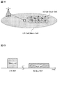
図1は、将来の無線通信システムの導入形態の一例を示す図である。図1Aに示すように、5Gなどの将来の無線通信システムは、既存のLTEシステムに重畳(オーバーレイ)するように導入されることが想定される。
FIG. 1 is a diagram showing an example of a form of introduction of a future wireless communication system. As shown in FIG. 1A, it is assumed that future wireless communication systems such as 5G will be introduced so as to be superimposed (overlaid) on the existing LTE system.
例えば、図1Aでは、既存のLTEシステムの無線アクセス方式(LTE RAT)のセル(LTEセル)内に、将来の無線通信システムの無線アクセス方式(5G New RAT)の多数のセル(5Gセル)が配置される。図1Aに示すように、LTEセルは、相対的に大きいカバレッジを有するマクロセルであり、5GセルはLTEセルよりも小さいカバレッジを有するスモールセルであってもよい。
For example, in FIG. 1A, a number of cells (5G New RAT) of a radio access system (5G New RAT) of a future radio communication system are included in a cell (LTE cell) of a radio access system (LTE RAT) of an existing LTE system. Be placed. As shown in FIG. 1A, the LTE cell may be a macro cell having a relatively large coverage, and the 5G cell may be a small cell having a smaller coverage than the LTE cell.
また、図1Bに示すように、5G New RATのセル(例えば、スモールセル)では、LTE RATのセル(例えば、マクロセル)よりも高い周波数帯を利用することも想定される。
Also, as shown in FIG. 1B, it is assumed that a 5G New RAT cell (for example, a small cell) uses a higher frequency band than an LTE RAT cell (for example, a macro cell).
図2は、5G New RATの一例を示す図である。図2Aに示すように、5G New RATでは、周波数パラメータ(例えば、サブキャリア間隔や帯域幅など)をLTE RATのN倍とし、時間パラメータ(例えば、シンボル長)を1/N倍にすることが想定される。この場合、複数のシンボルで構成されるTTIをLTE RATの1msよりも短くできるので、低遅延を実現し易くなる。
FIG. 2 is a diagram illustrating an example of a 5G New RAT. As shown in FIG. 2A, in 5G New RAT, frequency parameters (for example, subcarrier spacing and bandwidth) are set to N times that of LTE RAT, and time parameters (for example, symbol length) are set to 1 / N times. is assumed. In this case, since the TTI composed of a plurality of symbols can be shorter than 1 ms of LTE RAT, it is easy to realize low delay.
或いは、5G New RATでは、周波数パラメータ(例えば、サブキャリア間隔や帯域幅など)をLTE RATの1/N倍とし、時間パラメータ(例えば、シンボル長)をN倍にすることが想定される。この場合、シンボル長が長くなるので、フェージングに対する耐性を向上させることができる(フェージングに対してロバストになる)。
Alternatively, in the 5G New RAT, it is assumed that the frequency parameter (for example, subcarrier interval and bandwidth) is 1 / N times that of LTE RAT, and the time parameter (for example, symbol length) is N times. In this case, since the symbol length becomes long, the resistance to fading can be improved (becomes robust against fading).
以上のような5G New RATでは、DLとULとのトラフィックの変動に柔軟に対応して無線リソースの利用効率を向上させるとともに、低遅延化を図ることが求められる。このため、5G New RATでは、TDDにおいて、DLとULとをTTI毎に動的に切り替え可能とすることが望まれる。この場合、ユーザ端末が、どのように各TTIがDL用又はUL用のいずれのTTIであるかを瞬時に判断し、DLとULとのTTI毎の切り替えに対応するかが問題となる。
In the 5G New RAT as described above, it is required to flexibly cope with fluctuations in traffic between DL and UL to improve utilization efficiency of radio resources and to reduce delay. For this reason, in 5G New RAT, it is desired that DL and UL can be dynamically switched for each TTI in TDD. In this case, it becomes a problem whether the user terminal instantaneously determines whether each TTI is a TTI for DL or UL, and corresponds to switching for each TTI between DL and UL.
例えば、ユーザ端末に対してDL受信又はUL送信の割り当てがあるTTIにおいては、ユーザ端末は、DL受信が割り当てられたTTIがDL用のTTIであること、UL送信が割り当てられたTTIがUL用のTTIであることを認識できる。
For example, in a TTI in which DL reception or UL transmission is assigned to a user terminal, the user terminal indicates that the TTI to which DL reception is assigned is a TTI for DL, and the TTI to which UL transmission is assigned is for UL. Can be recognized.
一方、ユーザ端末に対してDL受信又はUL送信の割り当てがないTTIにおいては、DLとULとがTTI毎に切り替えられると、ユーザ端末が、各TTIがDL用又はUL用のいずれのTTIであるかを認識できないことが想定される。
On the other hand, in a TTI in which DL reception or UL transmission is not allocated to a user terminal, when the DL and UL are switched for each TTI, the user terminal is either a TTI for each DL or UL. It is assumed that it cannot be recognized.
ところで、既存のLTEシステムのTDD(Rel.12 eIMTA:enhanced Interference Mitigation & Traffic Adaptation)では、無線フレーム内のDLサブフレームとULサブフレームとの構成を示すDL/UL構成(TDD DL/UL configuration)内のULサブフレームをDLサブフレームに動的に置き換えること、すなわち、無線フレーム(10ms)単位でDLとULとを動的に切り替えることが許容されている。
By the way, in the TDD (Rel.12 eIMTA: enhanced Interference Mitigation & Traffic Adaptation) of the existing LTE system, a DL / UL configuration (TDD DL / UL configuration) indicating a configuration of DL subframes and UL subframes in a radio frame Is dynamically replaced with a DL subframe, that is, it is allowed to dynamically switch between DL and UL in units of radio frames (10 ms).
図3は、eIMTAの一例を示す図である。図3に示すように、LTE TDDでは、予め定められた複数のDL/UL構成の中から準静的(semi-static)にDL/UL構成(図3では、DL/UL構成3)が選択される。eIMTAでは、選択されたDL/UL構成の一部のULサブフレームをDLサブフレームに動的(dynamic)に置き換えることができ、10ms毎に下り制御情報(DCI:Downlink Control Information)によってユーザ端末に通知される。
FIG. 3 is a diagram illustrating an example of eIMTA. As shown in FIG. 3, in LTE TDD, a DL / UL configuration (DL / UL configuration 3 in FIG. 3) is selected semi-statically from a plurality of predetermined DL / UL configurations. Is done. In eIMTA, some UL subframes of the selected DL / UL configuration can be dynamically replaced with DL subframes, and are transmitted to the user terminal by downlink control information (DCI: Downlink Control Information) every 10 ms. Be notified.
このように、DL/UL構成内の一部のULサブフレームだけをDLサブフレームに動的に切り替える場合、eIMTA対応のユーザ端末は、受信したDCIによって、ULサブフレームがDLサブフレームに置き換えられたことを認識できる。
As described above, when only some UL subframes in the DL / UL configuration are dynamically switched to the DL subframe, the eIMTA-compatible user terminal replaces the UL subframe with the DL subframe by the received DCI. I can recognize that.
また、DL/UL構成内のULサブフレームだけをDLサブフレームに動的に切り替える場合、eIMTA非対応のユーザ端末に対するバックワードコンパチビリティを確保できる。具体的には、eIMTA非対応のユーザ端末は、ULサブフレームでは、DLのチャネル状態の測定動作等を行わず、UL送信の割り当てがなければ原則としてUL送信も行わない。このため、ULサブフレームをDLサブフレームに置き換えても、eIMTA非対応のユーザ端末に影響はない。
In addition, when only the UL subframe in the DL / UL configuration is dynamically switched to the DL subframe, backward compatibility for a user terminal that does not support eIMTA can be ensured. Specifically, a user terminal that does not support eIMTA does not perform a DL channel state measurement operation or the like in a UL subframe, and does not perform UL transmission in principle unless UL transmission is assigned. For this reason, even if the UL subframe is replaced with the DL subframe, there is no influence on the user terminal that does not support eIMTA.
一方、5G RATでは、LTEシステムのeIMTAのように、eIMTAに非対応のユーザ端末に対するバックワードコンパチビリティを考慮する必要はない。このため、5G RATでは、eIMTAのようにDLとULとの切り替えに制約を設ける必要はなく、より柔軟にDLとULとを切り替えること、すなわち、TTI毎にDLとULとを動的に切り替え可能とすることが想定される。
On the other hand, in 5G RAT, it is not necessary to consider backward compatibility for user terminals that do not support eIMTA, like eIMTA of the LTE system. For this reason, in 5G RAT, there is no need to set restrictions on switching between DL and UL as in eIMTA, and switching between DL and UL more flexibly, that is, dynamically switching between DL and UL for each TTI. It is assumed to be possible.
しかしながら、DLとULとをTTI毎に切り替え可能とする場合、DL受信又はUL送信の割り当てがないTTIにおいては、ユーザ端末が、各TTIがDL用又はUL用のいずれのTTIであるかを認識できない恐れがある。
However, when switching between DL and UL for each TTI is possible, in a TTI without DL reception or UL transmission allocation, the user terminal recognizes which TTI is for each DL or UL. There is a fear that it cannot be done.
そこで、本発明者らは、DL用のTTIとUL用のTTIとの信号構成に基づいて、ユーザ端末が各TTIがDL用又はUL用のいずれのTTIであるかを識別可能とすることを着想し、本発明に至った。
Accordingly, the present inventors have made it possible for the user terminal to identify whether each TTI is a DL or UL TTI based on the signal configuration of the DL TTI and the UL TTI. Invented and led to the present invention.
本発明の一態様において、DL又はULをTTI毎に切り替え可能な無線通信システムで用いられるユーザ端末は、DL用のTTIでDL信号を受信する。当該ユーザ端末は、各TTIの信号構成に基づいてDL用のTTIであるか否かを判断して、上記DL信号の受信を制御する。
In one aspect of the present invention, a user terminal used in a wireless communication system capable of switching DL or UL for each TTI receives a DL signal using a DL TTI. The user terminal determines whether it is a TTI for DL based on the signal configuration of each TTI, and controls reception of the DL signal.
以下、本発明の一実施形態に係る無線通信方法について説明する。
Hereinafter, a wireless communication method according to an embodiment of the present invention will be described.
(第1の態様)
第1の態様では、ユーザ端末がDL用のTTIであるか否かを判断するための信号構成について説明する。DL用のTTIには、ユーザ端末がDL用のTTIであるか否かを判断するためのプリアンブルが含まれる。ユーザ端末は、各TTIにおけるプリアンブルの検出有無に応じてDL用のTTIであるか否かを判断する。
(First aspect)
In the first aspect, a signal configuration for determining whether or not a user terminal is a TTI for DL will be described. The DL TTI includes a preamble for determining whether or not the user terminal is a DL TTI. The user terminal determines whether or not it is a DL TTI depending on whether or not a preamble is detected in each TTI.
ここで、プリアンブルとは、無線基地局及びユーザ端末において既知の系列であり、セル固有(セルIDに基づいて生成)であってもよいし、送信ポイント固有(バーチャルIDに基づいて生成)であってもよいし、ビームパターン固有(ビームパターンの識別情報に基づいて生成)であってもよい。また、プリアンブルは、同期、セル認識、受信信号電力測定、チャネル状態情報推定などのいずれかに用いられるような参照信号の一種であってもよい。
Here, the preamble is a known sequence in the radio base station and the user terminal, and may be cell-specific (generated based on the cell ID) or transmission point-specific (generated based on the virtual ID). Alternatively, it may be unique to the beam pattern (generated based on the identification information of the beam pattern). The preamble may be a kind of reference signal used for any of synchronization, cell recognition, received signal power measurement, channel state information estimation, and the like.
図4は、第1の態様に係るDL用のTTIの構成の一例を示す図である。図4Aに示すように、DL用のTTIは、プリアンブルが割り当てられるシンボル(プリアンブルシンボル)と、下り制御チャネルが割り当てられるシンボル(制御シンボル)と、下りデータチャネルが割り当てられるシンボルとを含む。
FIG. 4 is a diagram illustrating an example of a configuration of a DL TTI according to the first aspect. As shown in FIG. 4A, the DL TTI includes a symbol to which a preamble is assigned (preamble symbol), a symbol to which a downlink control channel is assigned (control symbol), and a symbol to which a downlink data channel is assigned.
また、図4Aに示すように、プリアンブルシンボルは、TTI内の先頭に配置される。また、TTI内に分散されるように複数のプリアンブルシンボルが配置されてもよい。例えば、図4Aでは、TTI内の先頭のシンボルと5番目のシンボルとにプリアンブルシンボルが配置される。TTI内の先頭のシンボルにプリアンブルシンボルを配置することにより、ユーザ端末は、当該TTIがDL用のTTIであるか否かの判断を迅速に行うことができる。
Further, as shown in FIG. 4A, the preamble symbol is arranged at the head in the TTI. Also, a plurality of preamble symbols may be arranged so as to be distributed within the TTI. For example, in FIG. 4A, preamble symbols are arranged at the first symbol and the fifth symbol in the TTI. By arranging the preamble symbol at the head symbol in the TTI, the user terminal can quickly determine whether or not the TTI is a DL TTI.
また、TTI内のプリアンブルシンボルは、データシンボル及び/又は制御シンボルとシンボル長、サブキャリア間隔、サイクリックプリフィクス(CP)長の少なくともいずれかが異なっていてもよい。
Also, the preamble symbol in the TTI may be different from the data symbol and / or control symbol in at least one of the symbol length, subcarrier interval, and cyclic prefix (CP) length.
例えば、図4Aに示すように、プリアンブルシンボルのシンボル長は、データシンボル及び制御シンボルのシンボル長よりも短くてもよい。具体的には、図4Bに示すように、プリアンブルシンボルのサブキャリア間隔は、データシンボル(及び/又は、制御シンボル)のサブキャリア間隔のN倍であり、プリアンブルシンボルのシンボル長は、データシンボルのシンボル長の1/N倍であってもよい(Nは、正の整数、ここでは、N=3)。この場合、プリアンブルシンボルの検出時間を短くでき、低遅延を実現しやすくなる。
For example, as shown in FIG. 4A, the symbol length of the preamble symbol may be shorter than the symbol length of the data symbol and the control symbol. Specifically, as shown in FIG. 4B, the subcarrier interval of the preamble symbol is N times the subcarrier interval of the data symbol (and / or control symbol), and the symbol length of the preamble symbol is It may be 1 / N times the symbol length (N is a positive integer, here N = 3). In this case, the detection time of the preamble symbol can be shortened, and a low delay can be easily realized.
また、図示しないが、プリアンブルシンボルのサブキャリア間隔は、データシンボル及び/又は制御シンボルの1/N倍(Nは、正の整数)であり、プリアンブルシンボルのシンボル長は、データシンボルのシンボル長のN倍であってもよい。この場合、プリアンブルシンボルのフェージング耐性を向上させることができる。
Although not shown, the subcarrier interval of the preamble symbol is 1 / N times the data symbol and / or control symbol (N is a positive integer), and the symbol length of the preamble symbol is equal to the symbol length of the data symbol. N times may be sufficient. In this case, fading resistance of the preamble symbol can be improved.
また、図4Cに示すように、プリアンブルシンボルのCP長は、データシンボル(及び/又は、制御シンボル)のCP長と異なってもよく、例えば短くてもよい。
Also, as shown in FIG. 4C, the CP length of the preamble symbol may be different from the CP length of the data symbol (and / or control symbol), for example, may be shorter.
なお、ユーザ端末は、以上のようなプリアンブルシンボルに基づいて、DL用のTTDであるか否かの判断だけでなく、他の動作を行ってもよい。例えば、ユーザ端末は、プリアンブルシンボルに基づいて、チャネル推定及び/又は時間周波数オフセットの補正を行ってもよい。この場合、図4Aに示すように、DL内のTTI内に複数のプリアンブルシンボルが設けることで、チャネル推定精度を向上させたり、時間周波数オフセットの補正精度を向上させたりすることができる。
Note that the user terminal may perform other operations based on the preamble symbol as described above, in addition to determining whether or not it is a TTD for DL. For example, the user terminal may perform channel estimation and / or time frequency offset correction based on the preamble symbol. In this case, as shown in FIG. 4A, by providing a plurality of preamble symbols in the TTI in the DL, it is possible to improve channel estimation accuracy and improve time-frequency offset correction accuracy.
(第2の態様)
第2の態様では、ユーザ端末におけるDL用のTTIであるか否かの判断動作について詳細に説明する。
(Second aspect)
In the second mode, the operation for determining whether or not the user terminal is a TTI for DL will be described in detail.
図5は、第2の態様に係るユーザ端末におけるTTIの判断(認識)動作例を示すフローチャートである。ユーザ端末は、TTI毎に図5に示す判断動作を行う。なお、図5は、例示にすぎず、ユーザ端末の判断動作は、これに限られない。
FIG. 5 is a flowchart showing an example of TTI determination (recognition) operation in the user terminal according to the second aspect. The user terminal performs the determination operation shown in FIG. 5 for each TTI. Note that FIG. 5 is merely an example, and the determination operation of the user terminal is not limited to this.
図5に示すように、ユーザ端末は、無線基地局からの指示情報(例えば、ULグラント)によりUL送信が指示されたTTIであるか否かを判断する(ステップS101)。指示情報によりUL送信が指示されたTTIである場合(ステップS101;YES)、ユーザ端末は、ステップS102以降のTTIの判断動作を省略し、当該TTIがUL用のTTIであると判断し(ステップS105)、当該TTIでUL送信を行う。
As shown in FIG. 5, the user terminal determines whether or not the TTI is instructed to transmit UL by instruction information (for example, UL grant) from the radio base station (step S101). If the TTI is instructed to be transmitted by the instruction information (step S101; YES), the user terminal omits the TTI determination operation after step S102 and determines that the TTI is a UL TTI (step S101). S105), UL transmission is performed with the TTI.
一方、UL送信が指示されたTTIでない場合(ステップS101;NO)、ユーザ端末は、当該TTIにおいてプリアンブルが含まれるか否かを判断する(ステップS102)。TTI内にプリアンブルが検出される場合(ステップS102;YES)、ユーザ端末は、当該TTIがDL用のTTIであると判断する(ステップS103)。ユーザ端末は、当該DL用のTTIに含まれる参照信号を用いて、時間周波数同期、AGC(Automatic Gain Control)、チャネル推定、下り制御チャネルの復調の少なくとも一つを行うことができる(ステップS104)。
On the other hand, when the TTI is not instructed to transmit UL (step S101; NO), the user terminal determines whether or not a preamble is included in the TTI (step S102). When the preamble is detected in the TTI (step S102; YES), the user terminal determines that the TTI is a DL TTI (step S103). The user terminal can perform at least one of time-frequency synchronization, AGC (Automatic Gain Control), channel estimation, and downlink control channel demodulation using the reference signal included in the DL TTI (step S104). .
一方、ユーザ端末は、TTI内にプリアンブルが検出されない場合(ステップS102;NO)、ユーザ端末は、当該TTIがUL用のTTIである(DL用のTTIではない)と判断する(ステップS105)。この場合、ユーザ端末は、DL用のTTIであると判断する場合に行う動作(上述の時間周波数同期、AGC、チャネル推定、下り制御チャネルの復調の少なくとも一つ)を行わない。
On the other hand, when the preamble is not detected in the TTI (step S102; NO), the user terminal determines that the TTI is a UL TTI (not a DL TTI) (step S105). In this case, the user terminal does not perform the operation (at least one of the above-described time-frequency synchronization, AGC, channel estimation, and downlink control channel demodulation) performed when determining that it is a DL TTI.
なお、図5では、無線基地局からの送信指示情報(例えば、ULグラント)によりUL送信が指示されたTTIである場合(ステップS101;YES)、ユーザ端末は、ステップS102以降の動作を省略するが、省略しなくともよい。UL送信が指示されるTTIであるにも関わらず、当該TTIでプリアンブルが検出され、当該TTIがDL用のTTIであると判断される場合、ユーザ端末は、当該UL送信を中止(ドロップ)してもよい。
In FIG. 5, in the case of a TTI in which UL transmission is instructed by transmission instruction information (for example, UL grant) from the radio base station (step S <b> 101; YES), the user terminal omits the operations after step S <b> 102. However, it may not be omitted. When the preamble is detected in the TTI even though the UL transmission is instructed, and the TTI is determined to be a DL TTI, the user terminal stops (drops) the UL transmission. May be.
また、ユーザ端末は、間欠受信(DRX:Discontinuous Reception)状態である場合、上記TTIの判断動作を省略してもよい。
In addition, when the user terminal is in a discontinuous reception (DRX) state, the TTI determination operation may be omitted.
また、ユーザ端末は、Deactivated状態のSecondaryセル(SCell、セカンダリセル)に対しては、上記TTIの判断動作を省略してもよい。
In addition, the user terminal may omit the above-described TTI determination operation for the secondary cell (SCell, secondary cell) in the deactivated state.
また、ユーザ端末は、無線基地局(ネットワーク)からのリソース情報に基づいて、上記TTIの判断動作を省略してもよい。具体的には、ユーザ端末は、無線基地局から、上記TTIの判断動作を省略可能なリソースを指示するリソース情報(例えば、周期、オフセットなど)を上位レイヤシグナリング(例えば、RRC(Radio Resource Control)シグナリング)や報知情報により受信し、当該リソース情報に基づいて上記TTIの判断動作を省略する。
Also, the user terminal may omit the TTI determination operation based on the resource information from the radio base station (network). Specifically, the user terminal sends resource information (for example, period, offset, etc.) indicating a resource that can omit the TTI determination operation from the radio base station to higher layer signaling (for example, RRC (Radio Resource Control)). Signaling) or broadcast information, and the TTI determination operation is omitted based on the resource information.
例えば、長周期のDL専用のTTIが設定され、当該DL専用のTTIにおいて、同期信号やセル認識又は/及び測定用信号を送信することが想定される。この場合、無線基地局は、当該DL専用のTTIの周期及びオフセットを示すリソース情報をユーザ端末に送信する。ユーザ端末は、リソース情報が示す周期及びオフセットによって特定されるDL専用のTTIにおいて、上記TTIの判断動作を省略して(プリアンブルの検出有無に関わらず)、DL用のTTIであると判断する。
For example, it is assumed that a long-period DL-dedicated TTI is set and a synchronization signal, cell recognition, and / or measurement signal is transmitted in the DL-dedicated TTI. In this case, the radio base station transmits resource information indicating the period and offset of the DL dedicated TTI to the user terminal. The user terminal omits the TTI determination operation (regardless of whether or not the preamble is detected) in the DL-dedicated TTI specified by the period and offset indicated by the resource information, and determines that it is a DL TTI.
以上、本実施形態に係る無線通信方法によれば、DL用のTTIには、ユーザ端末がDL用のTTIであるか否かを判断するためのプリアンブルシンボルが含まれる。このため、DL又はULをTTI毎に切り替え可能とする場合であっても、ユーザ端末は、各TTIにおけるプリアンブルの検出有無に応じてDL用のTTIであるか否かを判断できる。
As described above, according to the radio communication method according to the present embodiment, the DL TTI includes a preamble symbol for determining whether or not the user terminal is a DL TTI. For this reason, even when DL or UL can be switched for each TTI, the user terminal can determine whether or not the TTI is for DL depending on whether or not the preamble is detected in each TTI.
また、本実施形態に係る無線通信方法によれば、ユーザ端末は、既存のLTEシステム(eIMTA)のように、下り制御チャネルのブラインド復号してDCIを取得せずとも、各TTIにおける信号構成(例えば、プリアンブルの検出有無)によりDL用のTTIであるか否かを判断できる。この結果、低遅延化を図ることもできる。
Also, according to the radio communication method according to the present embodiment, the user terminal can perform signal configuration in each TTI (blind decoding of the downlink control channel without acquiring DCI as in the existing LTE system (eIMTA)). For example, whether or not the TTI is for DL can be determined based on whether or not a preamble is detected. As a result, it is possible to reduce the delay.
なお、本実施形態に係る無線通信方法では、DL用のTTI長とUL用のTTI長とを異ならせることもできる。例えば、UL用のTTI長は、DL用のTTI長の1/N倍(Nは、正の整数)であってもよい。また、DL用のTTIには、DL信号に対するフィードバック信号(例えば、HARQ-ACK:Hybrid Automatic Repeat reQuest-ACKnowledgement)を送信するためのシンボルが含まれてもよい。
In the wireless communication method according to the present embodiment, the DL TTI length and the UL TTI length may be different. For example, the UL TTI length may be 1 / N times the DL TTI length (N is a positive integer). Also, the DL TTI may include a symbol for transmitting a feedback signal for the DL signal (for example, HARQ-ACK: Hybrid Automatic Repeat reQuest-ACKnowledgement).
(無線通信システム)
以下、本発明の一実施形態に係る無線通信システムの構成について説明する。この無線通信システムでは、上記無線通信方法が適用される。なお、上記各態様に係る無線通信方法は、単独で適用されてもよいし、組み合わせて適用されてもよい。
(Wireless communication system)
Hereinafter, the configuration of a wireless communication system according to an embodiment of the present invention will be described. In this wireless communication system, the above wireless communication method is applied. In addition, the radio | wireless communication method which concerns on each said aspect may be applied independently, and may be applied in combination.
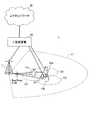
図6は、本発明の一実施形態に係る無線通信システムの概略構成の一例を示す図である。無線通信システム1では、LTEシステムのシステム帯域幅(例えば、20MHz)を1単位とする複数の基本周波数ブロック(コンポーネントキャリア)を一体としたキャリアアグリゲーション(CA)及び/又はデュアルコネクティビティ(DC)を適用することができる。なお、無線通信システム1は、SUPER 3G、LTE-A(LTE-Advanced)、IMT-Advanced、4G、5G、FRA(Future Radio Access)などと呼ばれても良い。また、無線通信システム1では、TDDが適用され、ULとDLとをTTI毎に切り替え可能である。
FIG. 6 is a diagram illustrating an example of a schematic configuration of a wireless communication system according to an embodiment of the present invention. In the radio communication system 1, carrier aggregation (CA) and / or dual connectivity (DC) in which a plurality of basic frequency blocks (component carriers) each having a system bandwidth (for example, 20 MHz) of the LTE system as one unit are applied. can do. The wireless communication system 1 may be referred to as SUPER 3G, LTE-A (LTE-Advanced), IMT-Advanced, 4G, 5G, FRA (Future Radio Access), or the like. Further, in the wireless communication system 1, TDD is applied, and UL and DL can be switched for each TTI.
図6に示す無線通信システム1は、マクロセルC1を形成する無線基地局11と、マクロセルC1内に配置され、マクロセルC1よりも狭いスモールセルC2を形成する無線基地局12a~12cとを備えている。また、マクロセルC1及び各スモールセルC2には、ユーザ端末20が配置されている。
The radio communication system 1 shown in FIG. 6 includes a radio base station 11 that forms a macro cell C1, and radio base stations 12a to 12c that are arranged in the macro cell C1 and form a small cell C2 that is narrower than the macro cell C1. . Moreover, the user terminal 20 is arrange | positioned at the macrocell C1 and each small cell C2.
ユーザ端末20は、無線基地局11及び無線基地局12の双方に接続することができる。ユーザ端末20は、異なる周波数を用いるマクロセルC1とスモールセルC2を、CA又はDCにより同時に使用することが想定される。また、ユーザ端末20は、複数のセル(CC)(例えば、6個以上のCC)を用いてCA又はDCを適用することができる。
The user terminal 20 can be connected to both the radio base station 11 and the radio base station 12. It is assumed that the user terminal 20 uses the macro cell C1 and the small cell C2 that use different frequencies simultaneously by CA or DC. In addition, the user terminal 20 can apply CA or DC using a plurality of cells (CC) (for example, six or more CCs).
ユーザ端末20と無線基地局11との間は、相対的に低い周波数帯域(例えば、2GHz)で帯域幅が狭いキャリア(既存キャリア、Legacy carrierなどと呼ばれる)を用いて通信を行うことができる。一方、ユーザ端末20と無線基地局12との間は、相対的に高い周波数帯域(例えば、3.5GHz、5GHzなど)で帯域幅が広いキャリアが用いられてもよいし、無線基地局11との間と同じキャリアが用いられてもよい。なお、各無線基地局が利用する周波数帯域の構成はこれに限られない。
Communication between the user terminal 20 and the radio base station 11 can be performed using a carrier having a relatively low frequency band (for example, 2 GHz) and a narrow bandwidth (referred to as an existing carrier or a legacy carrier). On the other hand, a carrier having a relatively high frequency band (for example, 3.5 GHz, 5 GHz, etc.) and a wide bandwidth may be used between the user terminal 20 and the radio base station 12, or The same carrier may be used. The configuration of the frequency band used by each radio base station is not limited to this.
無線基地局11と無線基地局12との間(又は、2つの無線基地局12間)は、有線接続(例えば、CPRI(Common Public Radio Interface)に準拠した光ファイバ、X2インターフェースなど)又は無線接続する構成とすることができる。
Between the wireless base station 11 and the wireless base station 12 (or between the two wireless base stations 12), a wired connection (for example, an optical fiber compliant with CPRI (Common Public Radio Interface), an X2 interface, etc.) or a wireless connection It can be set as the structure to do.
無線基地局11及び各無線基地局12は、それぞれ上位局装置30に接続され、上位局装置30を介してコアネットワーク40に接続される。なお、上位局装置30には、例えば、アクセスゲートウェイ装置、無線ネットワークコントローラ(RNC)、モビリティマネジメントエンティティ(MME)などが含まれるが、これに限定されるものではない。また、各無線基地局12は、無線基地局11を介して上位局装置30に接続されてもよい。
The radio base station 11 and each radio base station 12 are connected to the higher station apparatus 30 and connected to the core network 40 via the higher station apparatus 30. The upper station device 30 includes, for example, an access gateway device, a radio network controller (RNC), a mobility management entity (MME), and the like, but is not limited thereto. Each radio base station 12 may be connected to the higher station apparatus 30 via the radio base station 11.
なお、無線基地局11は、相対的に広いカバレッジを有する無線基地局であり、マクロ基地局、集約ノード、eNB(eNodeB)、送受信ポイント、などと呼ばれてもよい。また、無線基地局12は、局所的なカバレッジを有する無線基地局であり、スモール基地局、マイクロ基地局、ピコ基地局、フェムト基地局、HeNB(Home eNodeB)、RRH(Remote Radio Head)、送受信ポイントなどと呼ばれてもよい。以下、無線基地局11及び12を区別しない場合は、無線基地局10と総称する。
The radio base station 11 is a radio base station having a relatively wide coverage, and may be called a macro base station, an aggregation node, an eNB (eNodeB), a transmission / reception point, or the like. The radio base station 12 is a radio base station having local coverage, and includes a small base station, a micro base station, a pico base station, a femto base station, a HeNB (Home eNodeB), an RRH (Remote Radio Head), and transmission / reception. It may be called a point. Hereinafter, when the radio base stations 11 and 12 are not distinguished, they are collectively referred to as a radio base station 10.
各ユーザ端末20は、LTE、LTE-Aなどの各種通信方式に対応した端末であり、移動通信端末だけでなく固定通信端末を含んでもよい。
Each user terminal 20 is a terminal compatible with various communication methods such as LTE and LTE-A, and may include not only a mobile communication terminal but also a fixed communication terminal.
無線通信システム1においては、無線アクセス方式として、下りリンク(DL)にOFDMA(直交周波数分割多元接続)が適用され、上りリンク(UL)にSC-FDMA(シングルキャリア-周波数分割多元接続)が適用される。OFDMAは、周波数帯域を複数の狭い周波数帯域(サブキャリア)に分割し、各サブキャリアにデータをマッピングして通信を行うマルチキャリア伝送方式である。SC-FDMAは、システム帯域幅を端末毎に1つ又は連続したリソースブロックからなる帯域に分割し、複数の端末が互いに異なる帯域を用いることで、端末間の干渉を低減するシングルキャリア伝送方式である。なお、DL及びULの無線アクセス方式は、これらの組み合わせに限られず、ULでOFDMAが用いられてもよい。また、DL及び/又はULで、NOMA(非直交多元接続)(電力多元接続ともいう)が適用されてもよい。
In the wireless communication system 1, OFDMA (Orthogonal Frequency Division Multiple Access) is applied to the downlink (DL) and SC-FDMA (Single Carrier-Frequency Division Multiple Access) is applied to the uplink (UL) as the radio access scheme. Is done. OFDMA is a multi-carrier transmission scheme that performs communication by dividing a frequency band into a plurality of narrow frequency bands (subcarriers) and mapping data to each subcarrier. SC-FDMA is a single-carrier transmission scheme that reduces interference between terminals by dividing the system bandwidth into bands consisting of one or continuous resource blocks for each terminal and using a plurality of terminals with mutually different bands. is there. The DL and UL radio access schemes are not limited to these combinations, and OFDMA may be used in the UL. In addition, NOMA (non-orthogonal multiple access) (also referred to as power multiple access) may be applied in DL and / or UL.
無線通信システム1では、下りリンクのチャネルとして、各ユーザ端末20で共有される下りデータチャネル(PDSCH:Physical Downlink Shared Channel)、報知チャネル(PBCH:Physical Broadcast Channel)、L1/L2制御チャネル(L1/L2制御信号)などが用いられる。PDSCHにより、ユーザデータや上位レイヤ制御情報、SIB(System Information Block)などが伝送される。また、PBCHにより、MIB(Master Information Block)が伝送される。
In the wireless communication system 1, as downlink channels, a downlink data channel (PDSCH: Physical Downlink Shared Channel) shared by each user terminal 20, a broadcast channel (PBCH: Physical Broadcast Channel), an L1 / L2 control channel (L1 / L2 control signal) or the like is used. User data, higher layer control information, SIB (System Information Block), etc. are transmitted by PDSCH. Also, MIB (Master Information Block) is transmitted by PBCH.
L1/L2制御チャネルは、下り制御チャネル(PDCCH(Physical Downlink Control Channel)、EPDCCH(Enhanced Physical Downlink Control Channel))、PCFICH(Physical Control Format Indicator Channel)、PHICH(Physical Hybrid-ARQ Indicator Channel)などを含む。PDCCHにより、PDSCH及びPUSCHのスケジューリング情報を含む下り制御情報(DCI:Downlink Control Information)などが伝送される。PCFICHにより、PDCCHに用いるOFDMシンボル数が伝送される。PHICHにより、PUSCHに対するHARQの送達確認情報(ACK/NACK)が伝送される。EPDCCHは、PDSCH(下りデータチャネル)と周波数分割多重され、PDCCHと同様にDCIなどの伝送に用いられる。
L1 / L2 control channels include downlink control channels (PDCCH (Physical Downlink Control Channel), EPDCCH (Enhanced Physical Downlink Control Channel)), PCFICH (Physical Control Format Indicator Channel), PHICH (Physical Hybrid-ARQ Indicator Channel), etc. . Downlink control information (DCI: Downlink Control Information) including scheduling information of PDSCH and PUSCH is transmitted by PDCCH. The number of OFDM symbols used for PDCCH is transmitted by PCFICH. The HAICH transmission confirmation information (ACK / NACK) for PUSCH is transmitted by PHICH. EPDCCH is frequency-division multiplexed with PDSCH (downlink data channel), and is used for transmission of DCI and the like in the same way as PDCCH.
無線通信システム1では、上りリンクのチャネルとして、各ユーザ端末20で共有される上りデータチャネル(PUSCH:Physical Uplink Shared Channel)、上り制御チャネル(PUCCH:Physical Uplink Control Channel)、ランダムアクセスチャネル(PRACH:Physical Random Access Channel)などが用いられる。上りデータチャネルにより、ユーザデータ、上位レイヤ制御情報が伝送される。送達確認情報(ACK/NACK)や無線品質情報(CQI)などの少なくも一つを含む上り制御情報(UCI:Uplink Control Information)は、上りデータチャネル又は上り制御チャネルにより、伝送される。ランダムアクセスチャネルにより、セルとの接続確立のためのランダムアクセスプリアンブルが伝送される。
In the wireless communication system 1, as an uplink channel, an uplink data channel (PUSCH) shared by each user terminal 20, an uplink control channel (PUCCH: Physical Uplink Control Channel), a random access channel (PRACH: Physical Random Access Channel) is used. User data and higher layer control information are transmitted through the uplink data channel. Uplink control information (UCI) including at least one of acknowledgment information (ACK / NACK) and radio quality information (CQI) is transmitted by an uplink data channel or an uplink control channel. A random access preamble for establishing connection with the cell is transmitted by the random access channel.
<無線基地局>
図7は、本発明の一実施形態に係る無線基地局の全体構成の一例を示す図である。無線基地局10は、複数の送受信アンテナ101と、アンプ部102と、送受信部103と、ベースバンド信号処理部104と、呼処理部105と、伝送路インターフェース106とを備えている。なお、送受信アンテナ101、アンプ部102、送受信部103は、それぞれ1つ以上を含むように構成されてもよい。
<Wireless base station>
FIG. 7 is a diagram illustrating an example of an overall configuration of a radio base station according to an embodiment of the present invention. The radio base station 10 includes a plurality of transmission / reception antennas 101, an amplifier unit 102, a transmission / reception unit 103, a baseband signal processing unit 104, a call processing unit 105, and a transmission path interface 106. Note that each of the transmission / reception antenna 101, the amplifier unit 102, and the transmission / reception unit 103 may be configured to include one or more.
下りリンクにより無線基地局10からユーザ端末20に送信されるユーザデータは、上位局装置30から伝送路インターフェース106を介してベースバンド信号処理部104に入力される。
User data transmitted from the radio base station 10 to the user terminal 20 via the downlink is input from the higher station apparatus 30 to the baseband signal processing unit 104 via the transmission path interface 106.
ベースバンド信号処理部104では、ユーザデータに関して、PDCP(Packet Data Convergence Protocol)レイヤの処理、ユーザデータの分割・結合、RLC(Radio Link Control)再送制御などのRLCレイヤの送信処理、MAC(Medium Access Control)再送制御(例えば、HARQ(Hybrid Automatic Repeat reQuest)の送信処理)、スケジューリング、伝送フォーマット選択、チャネル符号化、逆高速フーリエ変換(IFFT:Inverse Fast Fourier Transform)処理、プリコーディング処理などの送信処理が行われて送受信部103に転送される。また、DL制御信号に関しても、チャネル符号化や逆高速フーリエ変換などの送信処理が行われて、送受信部103に転送される。
In the baseband signal processing unit 104, with respect to user data, PDCP (Packet Data Convergence Protocol) layer processing, user data division / combination, RLC (Radio Link Control) retransmission control and other RLC layer transmission processing, MAC (Medium Access) Control) Retransmission control (for example, HARQ (Hybrid Automatic Repeat reQuest) transmission processing), scheduling, transmission format selection, channel coding, inverse fast Fourier transform (IFFT) processing, precoding processing, and other transmission processing Is transferred to the transmission / reception unit 103. The DL control signal is also subjected to transmission processing such as channel coding and inverse fast Fourier transform, and is transferred to the transmission / reception unit 103.
送受信部103は、ベースバンド信号処理部104からアンテナ毎にプリコーディングして出力されたベースバンド信号を無線周波数帯に変換して送信する。送受信部103で周波数変換された無線周波数信号は、アンプ部102により増幅され、送受信アンテナ101から送信される。
The transmission / reception unit 103 converts the baseband signal output by precoding for each antenna from the baseband signal processing unit 104 to a radio frequency band and transmits the converted signal. The radio frequency signal frequency-converted by the transmission / reception unit 103 is amplified by the amplifier unit 102 and transmitted from the transmission / reception antenna 101.
また、送受信部103は、ユーザ端末20に対するUL送信又はDL受信を指示する指示情報(例えば、ULグラントやDLアサインメント)を下り制御チャネルにより送信する。また、送受信部103は、TTIの判断動作を省略可能なリソースを指示するリソース情報(例えば、周期、オフセットなど)を上位レイヤシグナリングにより送信してもよい。
Further, the transmission / reception unit 103 transmits instruction information (for example, UL grant or DL assignment) instructing UL transmission or DL reception to the user terminal 20 through the downlink control channel. Further, the transmission / reception unit 103 may transmit resource information (for example, a period, an offset, etc.) indicating a resource that can omit the TTI determination operation by higher layer signaling.
本発明に係る技術分野での共通認識に基づいて説明されるトランスミッター/レシーバー、送受信回路又は送受信装置から構成することができる。なお、送受信部103は、一体の送受信部として構成されてもよいし、送信部及び受信部から構成されてもよい。
The transmitter / receiver, the transmission / reception circuit, or the transmission / reception device can be configured based on common recognition in the technical field according to the present invention. In addition, the transmission / reception part 103 may be comprised as an integral transmission / reception part, and may be comprised from a transmission part and a receiving part.
一方、UL信号については、送受信アンテナ101で受信された無線周波数信号がアンプ部102で増幅される。送受信部103はアンプ部102で増幅されたUL信号を受信する。送受信部103は、受信信号をベースバンド信号に周波数変換して、ベースバンド信号処理部104に出力する。
On the other hand, for the UL signal, the radio frequency signal received by the transmission / reception antenna 101 is amplified by the amplifier unit 102. The transmission / reception unit 103 receives the UL signal amplified by the amplifier unit 102. The transmission / reception unit 103 converts the frequency of the received signal into a baseband signal and outputs it to the baseband signal processing unit 104.
ベースバンド信号処理部104では、入力されたUL信号に含まれるユーザデータに対して、高速フーリエ変換(FFT:Fast Fourier Transform)処理、逆離散フーリエ変換(IDFT:Inverse Discrete Fourier Transform)処理、誤り訂正復号、MAC再送制御の受信処理、RLCレイヤ及びPDCPレイヤの受信処理がなされ、伝送路インターフェース106を介して上位局装置30に転送される。呼処理部105は、通信チャネルの設定や解放などの呼処理や、無線基地局10の状態管理や、無線リソースの管理を行う。
The baseband signal processing unit 104 performs Fast Fourier Transform (FFT) processing, Inverse Discrete Fourier Transform (IDFT) processing, and error correction on user data included in the input UL signal. Decoding, MAC retransmission control reception processing, RLC layer and PDCP layer reception processing are performed and transferred to the upper station apparatus 30 via the transmission path interface 106. The call processing unit 105 performs call processing such as communication channel setting and release, state management of the radio base station 10, and radio resource management.
伝送路インターフェース106は、所定のインターフェースを介して、上位局装置30と信号を送受信する。また、伝送路インターフェース106は、基地局間インターフェース(例えば、CPRI(Common Public Radio Interface)に準拠した光ファイバ、X2インターフェース)を介して隣接無線基地局10と信号を送受信(バックホールシグナリング)してもよい。
The transmission path interface 106 transmits and receives signals to and from the higher station apparatus 30 via a predetermined interface. The transmission path interface 106 transmits and receives (backhaul signaling) signals to and from the adjacent radio base station 10 via an interface between base stations (for example, an optical fiber compliant with CPRI (Common Public Radio Interface), X2 interface). Also good.
図8は、本実施形態に係る無線基地局の機能構成の一例を示す図である。なお、図8は、本実施形態における特徴部分の機能ブロックを主に示しており、無線基地局10は、無線通信に必要な他の機能ブロックも有しているものとする。図8に示すように、ベースバンド信号処理部104は、制御部301と、送信信号生成部302と、マッピング部303と、受信信号処理部304と、測定部305と、を備えている。
FIG. 8 is a diagram illustrating an example of a functional configuration of the radio base station according to the present embodiment. FIG. 8 mainly shows functional blocks of characteristic portions in the present embodiment, and the wireless base station 10 also has other functional blocks necessary for wireless communication. As illustrated in FIG. 8, the baseband signal processing unit 104 includes a control unit 301, a transmission signal generation unit 302, a mapping unit 303, a reception signal processing unit 304, and a measurement unit 305.
制御部301は、無線基地局10全体の制御を実施する。制御部301は、例えば、送信信号生成部302によるDL信号の生成や、マッピング部303による信号のマッピング、受信信号処理部304による信号の受信処理を制御する。
The control unit 301 controls the entire radio base station 10. The control unit 301 controls, for example, DL signal generation by the transmission signal generation unit 302, signal mapping by the mapping unit 303, and signal reception processing by the reception signal processing unit 304.
具体的には、制御部301は、DL用のTTIとUL用のTTIとの切り替えを制御する。例えば、制御部301は、DL及び/又はULのトラヒック量に基づいて、DL用のTTIとUL用のTTIとをTTI毎に切り替えてもよい。
Specifically, the control unit 301 controls switching between the DL TTI and the UL TTI. For example, the control unit 301 may switch between the DL TTI and the UL TTI for each TTI based on the DL and / or UL traffic volume.
また、制御部301は、DL用のTTIに、プリアンブルが割り当てられるプリアンブルシンボルを含めるように、送信信号生成部302及びマッピング部303を制御する。また、制御部301は、DL用のTTIに複数のプリアンブルシンボルを含めるように制御してもよい。
Also, the control unit 301 controls the transmission signal generation unit 302 and the mapping unit 303 so that a preamble symbol to which a preamble is assigned is included in the DL TTI. In addition, the control unit 301 may perform control so that a plurality of preamble symbols are included in the DL TTI.
また、制御部301は、プリアンブルシンボルを、データチャネル及び/又は制御チャネルが割当てられるシンボルとシンボル長、サブキャリア間隔、CP長の少なくともいずれかが異なるように、送信信号生成部302及びマッピング部302を制御してもよい(図4)。
Also, the control unit 301 transmits the preamble symbol to the transmission signal generation unit 302 and the mapping unit 302 so that at least one of the symbol length, the subcarrier interval, and the CP length is different from the symbol to which the data channel and / or control channel is allocated. May be controlled (FIG. 4).
また、制御部301は、下りデータチャネル、上りデータチャネルに対する無線リソースの割り当て(スケジューリング)を制御する。制御部301は、割り当てられた無線リソースにおけるUL送信又はDL受信を指示する指示情報を下り制御チャネルにより送信するように制御する。
Also, the control unit 301 controls radio resource allocation (scheduling) for the downlink data channel and the uplink data channel. The control unit 301 performs control so that instruction information instructing UL transmission or DL reception in the assigned radio resource is transmitted using the downlink control channel.
また、制御部301は、TTIの判断動作を省略可能なリソース(例えば、長周期のDL専用のTTI)を決定し、当該リソースを指示するリソース情報(例えば、周期、オフセットなど)を上位レイヤシグナリングにより送信するように制御してもよい。
Further, the control unit 301 determines a resource (for example, a long-period DL-dedicated TTI) that can omit the TTI determination operation, and transmits resource information (for example, a period, an offset, etc.) indicating the resource to higher layer signaling. It may be controlled so as to transmit.
制御部301は、本発明に係る技術分野での共通認識に基づいて説明されるコントローラ、制御回路又は制御装置から構成することができる。
The control unit 301 can be configured by a controller, a control circuit, or a control device described based on common recognition in the technical field according to the present invention.
送信信号生成部302は、制御部301からの指示に基づいて、DL信号(下りデータチャネル、下り制御チャネル(L1制御信号)、下り参照信号を含む)を生成して、マッピング部303に出力する。
The transmission signal generation unit 302 generates a DL signal (including a downlink data channel, a downlink control channel (L1 control signal), and a downlink reference signal) based on an instruction from the control unit 301, and outputs the DL signal to the mapping unit 303. .
具体的には、送信信号生成部302は、制御部301からの指示に基づいて、プリアンブルシンボルにマッピングされるプリアンブルを生成し、マッピング部303に出力する。ここで、プリアンブルは、無線基地局10及びユーザ端末20で既知の系列であり、セル固有、送信ポイント固有、又は、ビームパターン固有いずれかであってもよい。
Specifically, the transmission signal generation unit 302 generates a preamble that is mapped to the preamble symbol based on an instruction from the control unit 301, and outputs the preamble to the mapping unit 303. Here, the preamble is a sequence known by the radio base station 10 and the user terminal 20, and may be cell specific, transmission point specific, or beam pattern specific.
例えば、送信信号生成部302は、セルID、バーチャルセルID、又は、ビームパターンの識別情報のいずれかに基づいて、プリアンブルを生成してもよい。なお、プリアンブルの生成に用いられる情報(例えば、セルID、バーチャルセルID、又は、ビームパターンの識別情報など)は、ユーザ端末20に上位レイヤシグナリングにより通知されてもよい。
For example, the transmission signal generation unit 302 may generate a preamble based on any of cell ID, virtual cell ID, or beam pattern identification information. Information (for example, cell ID, virtual cell ID, or beam pattern identification information) used to generate the preamble may be notified to the user terminal 20 by higher layer signaling.
送信信号生成部302は、本発明に係る技術分野での共通認識に基づいて説明される信号生成器、信号生成回路又は信号生成装置とすることができる。
The transmission signal generation unit 302 can be a signal generator, a signal generation circuit, or a signal generation device described based on common recognition in the technical field according to the present invention.
マッピング部303は、制御部301からの指示に基づいて、送信信号生成部302で生成されたDL信号を、所定の無線リソースにマッピングして、送受信部103に出力する。
The mapping unit 303 maps the DL signal generated by the transmission signal generation unit 302 to a predetermined radio resource based on an instruction from the control unit 301, and outputs the DL signal to the transmission / reception unit 103.
具体的には、マッピング部303は、制御部301からの指示に基づいて、送信信号生成部302で生成されたDL信号を、プリアンブルシンボルにマッピングして、送受信部103に出力する。
Specifically, the mapping unit 303 maps the DL signal generated by the transmission signal generation unit 302 to a preamble symbol based on an instruction from the control unit 301, and outputs the DL symbol to the transmission / reception unit 103.
マッピング部303は、本発明に係る技術分野での共通認識に基づいて説明されるマッパー、マッピング回路又はマッピング装置とすることができる。
The mapping unit 303 can be a mapper, a mapping circuit, or a mapping device described based on common recognition in the technical field according to the present invention.
受信信号処理部304は、ユーザ端末20から送信されるUL信号(上りデータチャネル、上り制御チャネル、上り参照信号を含む)に対して、受信処理(例えば、デマッピング、復調、復号など)を行う。処理結果は、制御部301に出力される。
The reception signal processing unit 304 performs reception processing (for example, demapping, demodulation, decoding, etc.) on the UL signal (including the uplink data channel, the uplink control channel, and the uplink reference signal) transmitted from the user terminal 20. . The processing result is output to the control unit 301.
受信信号処理部304は、本発明に係る技術分野での共通認識に基づいて説明される信号処理器、信号処理回路又は信号処理装置、並びに、測定器、測定回路又は測定装置から構成することができる。
The reception signal processing unit 304 may be configured by a signal processor, a signal processing circuit or a signal processing device, and a measuring device, a measurement circuit or a measuring device, which are described based on common recognition in the technical field according to the present invention. it can.
測定部305は、ユーザ端末20からの上り参照信号を用いた測定を行い、測定結果を制御部301に出力する。測定部305は、本発明に係る技術分野での共通認識に基づいて説明される信号処理器、信号処理回路又は信号処理装置、並びに、測定器、測定回路又は測定装置から構成することができる。
The measurement unit 305 performs measurement using the uplink reference signal from the user terminal 20 and outputs the measurement result to the control unit 301. The measurement unit 305 can be configured by a signal processor, a signal processing circuit or a signal processing device, and a measurement device, a measurement circuit or a measurement device which are described based on common recognition in the technical field according to the present invention.
<ユーザ端末>
図9は、本発明の一実施形態に係るに係るユーザ端末の全体構成の一例を示す図である。ユーザ端末20は、MIMO伝送のための複数の送受信アンテナ201と、アンプ部202と、送受信部203と、ベースバンド信号処理部204と、アプリケーション部205と、を備えている。
<User terminal>
FIG. 9 is a diagram illustrating an example of an overall configuration of a user terminal according to an embodiment of the present invention. The user terminal 20 includes a plurality of transmission / reception antennas 201 for MIMO transmission, an amplifier unit 202, a transmission / reception unit 203, a baseband signal processing unit 204, and an application unit 205.
複数の送受信アンテナ201で受信された無線周波数信号は、それぞれアンプ部202で増幅される。各送受信部203はアンプ部202で増幅されたDL信号を受信する。送受信部203は、受信信号をベースバンド信号に周波数変換して、ベースバンド信号処理部204に出力する。
The radio frequency signals received by the plurality of transmission / reception antennas 201 are each amplified by the amplifier unit 202. Each transmitting / receiving unit 203 receives the DL signal amplified by the amplifier unit 202. The transmission / reception unit 203 converts the frequency of the received signal into a baseband signal and outputs it to the baseband signal processing unit 204.
ベースバンド信号処理部204は、入力されたベースバンド信号に対して、FFT処理や、誤り訂正復号、再送制御の受信処理などを行う。下りリンクのユーザデータは、アプリケーション部205に転送される。アプリケーション部205は、物理レイヤやMACレイヤより上位のレイヤに関する処理などを行う。また、下りリンクのデータのうち、報知情報もアプリケーション部205に転送される。
The baseband signal processing unit 204 performs FFT processing, error correction decoding, retransmission control reception processing, and the like on the input baseband signal. The downlink user data is transferred to the application unit 205. The application unit 205 performs processing related to layers higher than the physical layer and the MAC layer. In addition, broadcast information in the downlink data is also transferred to the application unit 205.
一方、上りリンクのユーザデータについては、アプリケーション部205からベースバンド信号処理部204に入力される。ベースバンド信号処理部204では、再送制御の送信処理(例えば、HARQの送信処理)や、チャネル符号化、プリコーディング、離散フーリエ変換(DFT:Discrete Fourier Transform)処理、IFFT処理などが行われて各送受信部203に転送される。送受信部203は、ベースバンド信号処理部204から出力されたベースバンド信号を無線周波数帯に変換して送信する。送受信部203で周波数変換された無線周波数信号は、アンプ部202により増幅され、送受信アンテナ201から送信される。
On the other hand, uplink user data is input from the application unit 205 to the baseband signal processing unit 204. The baseband signal processing unit 204 performs retransmission control transmission processing (for example, HARQ transmission processing), channel coding, precoding, discrete Fourier transform (DFT) processing, IFFT processing, and the like. It is transferred to the transmission / reception unit 203. The transmission / reception unit 203 converts the baseband signal output from the baseband signal processing unit 204 into a radio frequency band and transmits it. The radio frequency signal frequency-converted by the transmission / reception unit 203 is amplified by the amplifier unit 202 and transmitted from the transmission / reception antenna 201.
なお、送受信部203は、ユーザ端末20に対するUL送信又はDL受信を指示する指示情報(例えば、ULグラントやDLアサインメント)を下り制御チャネルにより受信する。また、送受信部203は、TTIの判断動作を省略可能なリソースを指示するリソース情報(例えば、周期、オフセットなど)を上位レイヤシグナリングにより受信してもよい。
The transmission / reception unit 203 receives instruction information (for example, UL grant or DL assignment) instructing UL transmission or DL reception to the user terminal 20 through the downlink control channel. Further, the transmission / reception unit 203 may receive resource information (for example, a period, an offset, etc.) indicating a resource that can omit the TTI determination operation by higher layer signaling.
送受信部203は、本発明に係る技術分野での共通認識に基づいて説明されるトランスミッター/レシーバー、送受信回路又は送受信装置とすることができる。また、送受信部203は、一体の送受信部として構成されてもよいし、送信部及び受信部から構成されてもよい。
The transmission / reception unit 203 can be a transmitter / receiver, a transmission / reception circuit, or a transmission / reception device described based on common recognition in the technical field according to the present invention. Further, the transmission / reception unit 203 may be configured as an integral transmission / reception unit, or may be configured from a transmission unit and a reception unit.
図10は、本実施形態に係るユーザ端末の機能構成の一例を示す図である。なお、図10においては、本実施形態における特徴部分の機能ブロックを主に示しており、ユーザ端末20は、無線通信に必要な他の機能ブロックも有しているものとする。図10に示すように、ユーザ端末20が有するベースバンド信号処理部204は、制御部401と、送信信号生成部402と、マッピング部403と、受信信号処理部404と、測定部405と、を備えている。
FIG. 10 is a diagram illustrating an example of a functional configuration of the user terminal according to the present embodiment. Note that FIG. 10 mainly shows functional blocks of characteristic portions in the present embodiment, and the user terminal 20 also has other functional blocks necessary for wireless communication. As shown in FIG. 10, the baseband signal processing unit 204 included in the user terminal 20 includes a control unit 401, a transmission signal generation unit 402, a mapping unit 403, a reception signal processing unit 404, and a measurement unit 405. I have.
制御部401は、ユーザ端末20全体の制御を実施する。制御部401は、例えば、送信信号生成部402による信号の生成や、マッピング部403による信号のマッピング、受信信号処理部404による信号の受信処理を制御する。
The control unit 401 controls the entire user terminal 20. The control unit 401 controls, for example, signal generation by the transmission signal generation unit 402, signal mapping by the mapping unit 403, and signal reception processing by the reception signal processing unit 404.
また、制御部401は、TTIの信号構成に基づいて各TTIがDL用のTTIであるか否かを判断して、DL信号の受信を制御する。また、制御部401は、各TTIにおいてプリアンブルの検出有無に応じてDL用のTTIであるか否かを判断してもよい。
Also, the control unit 401 determines whether each TTI is a DL TTI based on the TTI signal configuration, and controls the reception of the DL signal. In addition, the control unit 401 may determine whether or not the TTI is for DL depending on whether or not the preamble is detected in each TTI.
例えば、制御部401は、TTI内にプリアンブルが検出される場合、当該TTIをDL用のTTIであると判断してもよい。この場合、制御部401は、当該DL用のTTIに含まれる参照信号を用いて、時間周波数同期、AGC(Automatic Gain Control)、チャネル推定、下り制御チャネルの復調の少なくとも一つを行うように制御してもよい。
For example, when the preamble is detected in the TTI, the control unit 401 may determine that the TTI is a DL TTI. In this case, the control unit 401 performs control so as to perform at least one of time-frequency synchronization, AGC (Automatic Gain Control), channel estimation, and demodulation of the downlink control channel using the reference signal included in the DL TTI. May be.
或いは、制御部401は、TTI内にプリアンブルが検出されない場合、当該TTIをUL用のTTIであると判断してもよい。この場合、制御部401は、DL用のTTIと判断される場合に行われる上記処理を行わないように制御してもよい。
Alternatively, when the preamble is not detected in the TTI, the control unit 401 may determine that the TTI is a UL TTI. In this case, the control unit 401 may perform control so as not to perform the above-described processing that is performed when it is determined that the TTI is for DL.
また、制御部401は、無線基地局10から通知された所定のTTI(例えば、長周期のDL専用のTTI)について、プリアンブルの検出有無に関わらずDL用のTTIと判断してもよい。なお、所定のTTIは、無線基地局から上位レイヤシグナリングにより通知されるリソース情報(例えば、周期、オフセットなど)に基づいて決定されてもよい。
Further, the control unit 401 may determine that a predetermined TTI notified from the radio base station 10 (for example, a long-period DL-dedicated TTI) is a DL TTI regardless of whether or not a preamble is detected. The predetermined TTI may be determined based on resource information (for example, period, offset, etc.) notified from the radio base station through higher layer signaling.
また、制御部401は、無線基地局10からのUL送信の指示情報(例えば、ULグラント)に基づいてUL信号の送信を制御してもよい。具体的には、制御部401は、上記指示情報によりUL送信が指示されるTTIにおいて、DL用のTTIであるか否かの判断動作を中止してもよい。又は、制御部401は、上記指示情報によりUL送信が指示されるTTIにおいて、DL用のTTIであるか否かの判断動作を行い、当該TTIがDL用のTTIであると判断される場合、上記UL信号の送信を中止してもよい。
Further, the control unit 401 may control transmission of UL signals based on UL transmission instruction information (for example, UL grant) from the radio base station 10. Specifically, the control unit 401 may stop the operation of determining whether or not the TTI is for DL in the TTI in which UL transmission is instructed by the instruction information. Alternatively, the control unit 401 performs an operation of determining whether or not the TTI is a DL TTI in the TTI in which UL transmission is instructed by the instruction information, and when the TTI is determined to be a DL TTI, The transmission of the UL signal may be stopped.
また、制御部401は、TTI内のプリアンブルを用いてチャネル推定を行うように測定部405を制御してもよい。また、制御部401は、TTI内のプリアンブルを用いて、時間周波数オフセットの補正を行ってもよい。
Also, the control unit 401 may control the measurement unit 405 so as to perform channel estimation using a preamble in the TTI. Further, the control unit 401 may correct the time frequency offset using a preamble in the TTI.
制御部401は、本発明に係る技術分野での共通認識に基づいて説明されるコントローラ、制御回路又は制御装置から構成することができる。
The control unit 401 can be configured by a controller, a control circuit, or a control device described based on common recognition in the technical field according to the present invention.
送信信号生成部402は、制御部401からの指示に基づいて、UL信号(上りデータチャネル、上り制御チャネル、上り参照信号を含む)を生成して、マッピング部403に出力する。例えば、送信信号生成部402は、UCIを含む上り制御チャネルを生成する。また、送信信号生成部402は、上りユーザデータを含む上りデータチャネルを生成する。
The transmission signal generation unit 402 generates a UL signal (including an uplink data channel, an uplink control channel, and an uplink reference signal) based on an instruction from the control unit 401 and outputs the UL signal to the mapping unit 403. For example, the transmission signal generation unit 402 generates an uplink control channel including UCI. Also, the transmission signal generation unit 402 generates an uplink data channel including uplink user data.
送信信号生成部402は、本発明に係る技術分野での共通認識に基づいて説明される信号生成器、信号生成回路又は信号生成装置とすることができる。
The transmission signal generation unit 402 can be a signal generator, a signal generation circuit, or a signal generation device described based on common recognition in the technical field according to the present invention.
マッピング部403は、制御部401からの指示に基づいて、送信信号生成部402で生成されたUL信号(上り制御チャネル、上りデータチャネル、上り参照信号など)を無線リソースにマッピングして、送受信部203へ出力する。マッピング部403は、本発明に係る技術分野での共通認識に基づいて説明されるマッパー、マッピング回路又はマッピング装置とすることができる。
Based on an instruction from the control unit 401, the mapping unit 403 maps the UL signal (uplink control channel, uplink data channel, uplink reference signal, etc.) generated by the transmission signal generation unit 402 to a radio resource, and transmits and receives It outputs to 203. The mapping unit 403 may be a mapper, a mapping circuit, or a mapping device described based on common recognition in the technical field according to the present invention.
受信信号処理部404は、DL信号(下り制御チャネル(L1制御信号)、下りデータチャネルを含む)に対して、受信処理(例えば、デマッピング、復調、復号など)を行う。受信信号処理部404は、無線基地局10から受信した情報を、制御部401に出力する。受信信号処理部404は、例えば、報知情報、システム情報、RRCシグナリングなどの上位レイヤシグナリングによる制御情報、DCIなどを、制御部401に出力する。
The reception signal processing unit 404 performs reception processing (for example, demapping, demodulation, decoding, etc.) on the DL signal (including the downlink control channel (L1 control signal) and the downlink data channel). The reception signal processing unit 404 outputs information received from the radio base station 10 to the control unit 401. The received signal processing unit 404 outputs, for example, broadcast information, system information, control information by higher layer signaling such as RRC signaling, DCI, and the like to the control unit 401.
受信信号処理部404は、本発明に係る技術分野での共通認識に基づいて説明される信号処理器、信号処理回路又は信号処理装置から構成することができる。また、受信信号処理部404は、本発明に係る受信部を構成することができる。
The received signal processing unit 404 can be configured by a signal processor, a signal processing circuit, or a signal processing device described based on common recognition in the technical field according to the present invention. Further, the reception signal processing unit 404 can constitute a reception unit according to the present invention.
測定部405は、無線基地局10からの下り参照信号(例えば、CRS、CSI-RS)に基づいて、チャネル状態を測定(推定)し、測定結果を制御部401に出力する。また、測定部405は、TTI内のプリアンブルシンボルに割り当てられるプリアンブルに基づいて、チャネル状態を推定してもよい。
The measurement unit 405 measures (estimates) the channel state based on the downlink reference signal (for example, CRS, CSI-RS) from the radio base station 10 and outputs the measurement result to the control unit 401. Moreover, the measurement part 405 may estimate a channel state based on the preamble allocated to the preamble symbol in TTI.
測定部405は、本発明に係る技術分野での共通認識に基づいて説明される信号処理器、信号処理回路又は信号処理装置、並びに、測定器、測定回路又は測定装置から構成することができる。
The measuring unit 405 can be composed of a signal processor, a signal processing circuit or a signal processing device, and a measuring device, a measurement circuit or a measuring device which are explained based on common recognition in the technical field according to the present invention.
なお、上記実施形態の説明に用いたブロック図は、機能単位のブロックを示している。これらの機能ブロック(構成部)は、ハードウェア及びソフトウェアの任意の組み合わせによって実現される。また、各機能ブロックの実現手段は特に限定されない。すなわち、各機能ブロックは、物理的に結合した1つの装置により実現されてもよいし、物理的に分離した2つ以上の装置を有線又は無線で接続し、これら複数の装置により実現されてもよい。
In addition, the block diagram used for description of the said embodiment has shown the block of the functional unit. These functional blocks (components) are realized by any combination of hardware and software. Further, the means for realizing each functional block is not particularly limited. That is, each functional block may be realized by one physically coupled device, or may be realized by two or more physically separated devices connected by wire or wirelessly and by a plurality of these devices. Good.
例えば、無線基地局10やユーザ端末20の各機能の一部又は全ては、ASIC(Application Specific Integrated Circuit)、PLD(Programmable Logic Device)、FPGA(Field Programmable Gate Array)などのハードウェアを用いて実現されても良い。また、無線基地局10やユーザ端末20は、プロセッサ(CPU:Central Processing Unit)と、ネットワーク接続用の通信インターフェースと、メモリと、プログラムを保持したコンピュータ読み取り可能な記憶媒体と、を含むコンピュータ装置によって実現されてもよい。つまり、本発明の一実施形態に係る無線基地局、ユーザ端末などは、本発明に係る無線通信方法の処理を行うコンピュータとして機能してもよい。
For example, some or all of the functions of the radio base station 10 and the user terminal 20 are realized using hardware such as ASIC (Application Specific Integrated Circuit), PLD (Programmable Logic Device), and FPGA (Field Programmable Gate Array). May be. The radio base station 10 and the user terminal 20 are each a computer device including a processor (CPU: Central Processing Unit), a communication interface for network connection, a memory, and a computer-readable storage medium holding a program. It may be realized. That is, the radio base station, user terminal, and the like according to an embodiment of the present invention may function as a computer that performs processing of the radio communication method according to the present invention.
ここで、プロセッサやメモリなどは情報を通信するためのバスで接続される。また、コンピュータ読み取り可能な記録媒体は、例えば、フレキシブルディスク、光磁気ディスク、ROM(Read Only Memory)、EPROM(Erasable Programmable ROM)、CD-ROM(Compact Disc-ROM)、RAM(Random Access Memory)、ハードディスクなどの記憶媒体である。また、プログラムは、電気通信回線を介してネットワークから送信されても良い。また、無線基地局10やユーザ端末20は、入力キーなどの入力装置や、ディスプレイなどの出力装置を含んでいてもよい。
Here, the processor and memory are connected by a bus for communicating information. Computer-readable recording media include, for example, flexible disks, magneto-optical disks, ROM (Read Only Memory), EPROM (Erasable Programmable ROM), CD-ROM (Compact Disc-ROM), RAM (Random Access Memory), A storage medium such as a hard disk. In addition, the program may be transmitted from a network via a telecommunication line. The radio base station 10 and the user terminal 20 may include an input device such as an input key and an output device such as a display.
無線基地局10及びユーザ端末20の機能構成は、上述のハードウェアによって実現されてもよいし、プロセッサによって実行されるソフトウェアモジュールによって実現されてもよいし、両者の組み合わせによって実現されてもよい。プロセッサは、オペレーティングシステムを動作させてユーザ端末の全体を制御する。また、プロセッサは、記憶媒体からプログラム、ソフトウェアモジュールやデータをメモリに読み出し、これらに従って各種の処理を実行する。
The functional configurations of the radio base station 10 and the user terminal 20 may be realized by the hardware described above, may be realized by a software module executed by a processor, or may be realized by a combination of both. The processor controls the entire user terminal by operating an operating system. Further, the processor reads programs, software modules and data from the storage medium into the memory, and executes various processes according to these.
ここで、当該プログラムは、上記の各実施形態で説明した各動作を、コンピュータに実行させるプログラムであれば良い。例えば、ユーザ端末20の制御部401は、メモリに格納され、プロセッサで動作する制御プログラムによって実現されてもよく、他の機能ブロックについても同様に実現されてもよい。
Here, the program may be a program that causes a computer to execute the operations described in the above embodiments. For example, the control unit 401 of the user terminal 20 may be realized by a control program stored in a memory and operated by a processor, and may be realized similarly for other functional blocks.
また、ソフトウェア、命令などは、伝送媒体を介して送受信されてもよい。例えば、ソフトウェアが、同軸ケーブル、光ファイバケーブル、ツイストペア及びデジタル加入者回線(DSL)などの有線技術及び/又は赤外線、無線及びマイクロ波などの無線技術を使用してウェブサイト、サーバ、又は他のリモートソースから送信される場合、これらの有線技術及び/又は無線技術は、伝送媒体の定義内に含まれる。
Further, software, instructions, etc. may be transmitted / received via a transmission medium. For example, software may use websites, servers, or other devices using wired technology such as coaxial cable, fiber optic cable, twisted pair and digital subscriber line (DSL) and / or wireless technology such as infrared, wireless and microwave. When transmitted from a remote source, these wired and / or wireless technologies are included within the definition of transmission media.
なお、本明細書で説明した用語及び/又は本明細書の理解に必要な用語については、同一の又は類似する意味を有する用語と置き換えてもよい。例えば、チャネル及び/又はシンボルは信号(シグナリング)であってもよい。また、信号はメッセージであってもよい。また、コンポーネントキャリア(CC)は、キャリア周波数、セルなどと呼ばれてもよい。
Note that the terms described in this specification and / or terms necessary for understanding this specification may be replaced with terms having the same or similar meaning. For example, the channel and / or symbol may be a signal (signaling). The signal may be a message. Further, the component carrier (CC) may be called a carrier frequency, a cell, or the like.
また、本明細書で説明した情報、パラメータなどは、絶対値で表されてもよいし、所定の値からの相対値で表されてもよいし、対応する別の情報で表されてもよい。例えば、無線リソースはインデックスで指示されるものであってもよい。
In addition, information, parameters, and the like described in this specification may be represented by absolute values, may be represented by relative values from a predetermined value, or may be represented by other corresponding information. . For example, the radio resource may be indicated by an index.
本明細書で説明した情報、信号などは、様々な異なる技術のいずれかを使用して表されてもよい。例えば、上記の説明全体に渡って言及され得るデータ、命令、コマンド、情報、信号、ビット、シンボル、チップなどは、電圧、電流、電磁波、磁界若しくは磁性粒子、光場若しくは光子、又はこれらの任意の組み合わせによって表されてもよい。
The information, signals, etc. described herein may be represented using any of a variety of different technologies. For example, data, commands, commands, information, signals, bits, symbols, chips, etc. that may be referred to throughout the above description are voltages, currents, electromagnetic waves, magnetic fields or magnetic particles, light fields or photons, or any of these May be represented by a combination of
本明細書で説明した各態様/実施形態は単独で用いてもよいし、組み合わせて用いてもよいし、実行に伴って切り替えて用いてもよい。また、所定の情報の通知(例えば、「Xであること」の通知)は、明示的に行うものに限られず、暗黙的に(例えば、当該所定の情報の通知を行わないことによって)行われてもよい。
Each aspect / embodiment described in this specification may be used alone, in combination, or may be switched according to execution. In addition, notification of predetermined information (for example, notification of being “X”) is not limited to explicitly performed, but is performed implicitly (for example, by not performing notification of the predetermined information). May be.
情報の通知は、本明細書で説明した態様/実施形態に限られず、他の方法で行われてもよい。例えば、情報の通知は、物理レイヤシグナリング(例えば、DCI(Downlink Control Information)、UCI(Uplink Control Information))、上位レイヤシグナリング(例えば、RRC(Radio Resource Control)シグナリング、MAC(Medium Access Control)シグナリング、報知情報(MIB(Master Information Block)、SIB(System Information Block)))、その他の信号又はこれらの組み合わせによって実施されてもよい。また、RRCシグナリングは、RRCメッセージと呼ばれてもよく、例えば、RRC接続セットアップ(RRCConnectionSetup)メッセージ、RRC接続再構成(RRCConnectionReconfiguration)メッセージなどであってもよい。
The notification of information is not limited to the aspect / embodiment described in this specification, and may be performed by other methods. For example, notification of information includes physical layer signaling (for example, DCI (Downlink Control Information), UCI (Uplink Control Information)), upper layer signaling (for example, RRC (Radio Resource Control) signaling, MAC (Medium Access Control) signaling), It may be implemented by broadcast information (MIB (Master Information Block), SIB (System Information Block)), other signals, or a combination thereof. Further, the RRC signaling may be referred to as an RRC message, and may be, for example, an RRC connection setup (RRCConnectionSetup) message, an RRC connection reconfiguration (RRCConnectionReconfiguration) message, or the like.
本明細書で説明した各態様/実施形態は、LTE(Long Term Evolution)、LTE-A(LTE-Advanced)、SUPER 3G、IMT-Advanced、4G、5G、FRA(Future Radio Access)、CDMA2000、UMB(Ultra Mobile Broadband)、IEEE 802.11(Wi-Fi)、IEEE 802.16(WiMAX)、IEEE 802.20、UWB(Ultra-WideBand)、Bluetooth(登録商標)、その他の適切なシステムを利用するシステム及び/又はこれらに基づいて拡張された次世代システムに適用されてもよい。
Each aspect / embodiment described in this specification includes LTE (Long Term Evolution), LTE-A (LTE-Advanced), SUPER 3G, IMT-Advanced, 4G, 5G, FRA (Future Radio Access), CDMA2000, UMB (Ultra Mobile Broadband), IEEE 802.11 (Wi-Fi), IEEE 802.16 (WiMAX), IEEE 802.20, UWB (Ultra-WideBand), Bluetooth (registered trademark), and other appropriate systems The present invention may be applied to a system and / or a next generation system extended based on these systems.
本明細書で説明した各態様/実施形態の処理手順、シーケンス、フローチャートなどは、矛盾の無い限り、順序を入れ替えてもよい。例えば、本明細書で説明した方法については、例示的な順序で様々なステップの要素を提示しており、提示した特定の順序に限定されない。
The processing procedures, sequences, flowcharts and the like of each aspect / embodiment described in this specification may be switched in order as long as there is no contradiction. For example, the methods described herein present the elements of the various steps in an exemplary order and are not limited to the specific order presented.
以上、本発明について詳細に説明したが、当業者にとっては、本発明が本明細書中に説明した実施形態に限定されるものではないということは明らかである。本発明は、特許請求の範囲の記載により定まる本発明の趣旨及び範囲を逸脱することなく修正及び変更態様として実施することができる。したがって、本明細書の記載は、例示説明を目的とするものであり、本発明に対して何ら制限的な意味を有するものではない。
Although the present invention has been described in detail above, it will be apparent to those skilled in the art that the present invention is not limited to the embodiments described herein. The present invention can be implemented as modified and changed modes without departing from the spirit and scope of the present invention defined by the description of the scope of claims. Therefore, the description of the present specification is for illustrative purposes and does not have any limiting meaning to the present invention.
本出願は、2015年9月1日出願の特願2015-172357に基づく。この内容は、全てここに含めておく。
This application is based on Japanese Patent Application No. 2015-172357 filed on September 1, 2015. All this content is included here.