WO2017038659A1 - Motion detection device and three-dimensional shape measurement device using same - Google Patents
Motion detection device and three-dimensional shape measurement device using same Download PDFInfo
- Publication number
- WO2017038659A1 WO2017038659A1 PCT/JP2016/074907 JP2016074907W WO2017038659A1 WO 2017038659 A1 WO2017038659 A1 WO 2017038659A1 JP 2016074907 W JP2016074907 W JP 2016074907W WO 2017038659 A1 WO2017038659 A1 WO 2017038659A1
- Authority
- WO
- WIPO (PCT)
- Prior art keywords
- motion
- laser beam
- speed
- distance
- laser
- Prior art date
Links
- 238000001514 detection method Methods 0.000 title claims abstract description 89
- 238000005259 measurement Methods 0.000 title description 18
- 238000000034 method Methods 0.000 description 22
- 239000011159 matrix material Substances 0.000 description 9
- 238000013519 translation Methods 0.000 description 7
- 230000008901 benefit Effects 0.000 description 5
- 230000008859 change Effects 0.000 description 4
- 238000006243 chemical reaction Methods 0.000 description 3
- 230000009466 transformation Effects 0.000 description 3
- 230000000694 effects Effects 0.000 description 2
- 230000006870 function Effects 0.000 description 2
- 230000003993 interaction Effects 0.000 description 2
- 230000001133 acceleration Effects 0.000 description 1
- 238000007796 conventional method Methods 0.000 description 1
- 238000012937 correction Methods 0.000 description 1
- 230000005484 gravity Effects 0.000 description 1
- 238000009434 installation Methods 0.000 description 1
- 238000000691 measurement method Methods 0.000 description 1
- 238000012986 modification Methods 0.000 description 1
- 230000004048 modification Effects 0.000 description 1
- 230000003287 optical effect Effects 0.000 description 1
- 230000009467 reduction Effects 0.000 description 1
Images


Classifications
-
- G—PHYSICS
- G01—MEASURING; TESTING
- G01B—MEASURING LENGTH, THICKNESS OR SIMILAR LINEAR DIMENSIONS; MEASURING ANGLES; MEASURING AREAS; MEASURING IRREGULARITIES OF SURFACES OR CONTOURS
- G01B11/00—Measuring arrangements characterised by the use of optical techniques
- G01B11/24—Measuring arrangements characterised by the use of optical techniques for measuring contours or curvatures
-
- G—PHYSICS
- G01—MEASURING; TESTING
- G01S—RADIO DIRECTION-FINDING; RADIO NAVIGATION; DETERMINING DISTANCE OR VELOCITY BY USE OF RADIO WAVES; LOCATING OR PRESENCE-DETECTING BY USE OF THE REFLECTION OR RERADIATION OF RADIO WAVES; ANALOGOUS ARRANGEMENTS USING OTHER WAVES
- G01S17/00—Systems using the reflection or reradiation of electromagnetic waves other than radio waves, e.g. lidar systems
- G01S17/02—Systems using the reflection of electromagnetic waves other than radio waves
- G01S17/50—Systems of measurement based on relative movement of target
- G01S17/58—Velocity or trajectory determination systems; Sense-of-movement determination systems
-
- G—PHYSICS
- G01—MEASURING; TESTING
- G01B—MEASURING LENGTH, THICKNESS OR SIMILAR LINEAR DIMENSIONS; MEASURING ANGLES; MEASURING AREAS; MEASURING IRREGULARITIES OF SURFACES OR CONTOURS
- G01B21/00—Measuring arrangements or details thereof, where the measuring technique is not covered by the other groups of this subclass, unspecified or not relevant
-
- G—PHYSICS
- G01—MEASURING; TESTING
- G01C—MEASURING DISTANCES, LEVELS OR BEARINGS; SURVEYING; NAVIGATION; GYROSCOPIC INSTRUMENTS; PHOTOGRAMMETRY OR VIDEOGRAMMETRY
- G01C3/00—Measuring distances in line of sight; Optical rangefinders
- G01C3/02—Details
- G01C3/06—Use of electric means to obtain final indication
-
- G—PHYSICS
- G01—MEASURING; TESTING
- G01P—MEASURING LINEAR OR ANGULAR SPEED, ACCELERATION, DECELERATION, OR SHOCK; INDICATING PRESENCE, ABSENCE, OR DIRECTION, OF MOVEMENT
- G01P3/00—Measuring linear or angular speed; Measuring differences of linear or angular speeds
- G01P3/36—Devices characterised by the use of optical means, e.g. using infrared, visible, or ultraviolet light
-
- G—PHYSICS
- G01—MEASURING; TESTING
- G01S—RADIO DIRECTION-FINDING; RADIO NAVIGATION; DETERMINING DISTANCE OR VELOCITY BY USE OF RADIO WAVES; LOCATING OR PRESENCE-DETECTING BY USE OF THE REFLECTION OR RERADIATION OF RADIO WAVES; ANALOGOUS ARRANGEMENTS USING OTHER WAVES
- G01S17/00—Systems using the reflection or reradiation of electromagnetic waves other than radio waves, e.g. lidar systems
- G01S17/87—Combinations of systems using electromagnetic waves other than radio waves
-
- G—PHYSICS
- G01—MEASURING; TESTING
- G01S—RADIO DIRECTION-FINDING; RADIO NAVIGATION; DETERMINING DISTANCE OR VELOCITY BY USE OF RADIO WAVES; LOCATING OR PRESENCE-DETECTING BY USE OF THE REFLECTION OR RERADIATION OF RADIO WAVES; ANALOGOUS ARRANGEMENTS USING OTHER WAVES
- G01S17/00—Systems using the reflection or reradiation of electromagnetic waves other than radio waves, e.g. lidar systems
- G01S17/88—Lidar systems specially adapted for specific applications
- G01S17/89—Lidar systems specially adapted for specific applications for mapping or imaging
-
- G—PHYSICS
- G01—MEASURING; TESTING
- G01S—RADIO DIRECTION-FINDING; RADIO NAVIGATION; DETERMINING DISTANCE OR VELOCITY BY USE OF RADIO WAVES; LOCATING OR PRESENCE-DETECTING BY USE OF THE REFLECTION OR RERADIATION OF RADIO WAVES; ANALOGOUS ARRANGEMENTS USING OTHER WAVES
- G01S7/00—Details of systems according to groups G01S13/00, G01S15/00, G01S17/00
- G01S7/48—Details of systems according to groups G01S13/00, G01S15/00, G01S17/00 of systems according to group G01S17/00
- G01S7/481—Constructional features, e.g. arrangements of optical elements
- G01S7/4811—Constructional features, e.g. arrangements of optical elements common to transmitter and receiver
- G01S7/4812—Constructional features, e.g. arrangements of optical elements common to transmitter and receiver transmitted and received beams following a coaxial path
Definitions
- the present invention relates to a technique for detecting a motion of an object and a technique for measuring a three-dimensional shape of the object using the detected motion.
- Non-Patent Document 1 proposes a technique for detecting the motion of an unknown object and using it as an input device.
- a contact sensor is known as a technique for detecting the motion of an unknown object.
- an acceleration sensor, a GPS, a gyro sensor, a geomagnetic sensor, and the like are built in a smartphone or a game controller, and sensed motion information is used for interaction between the user and the system.
- a motion detection system using markers, ultrasonic waves, and magnets has also been developed (Non-patent Documents 2 and 3 below).
- these contact-type sensors have a limitation that they must be attached to an object in advance, and there is a problem that they are difficult to use for detecting motion of an unspecified object.
- Non-Patent Documents 4 and 5 a change in position and posture of an object with time is obtained by using various invariant feature amounts.
- Non-Patent Documents 6 and 7 the technique which estimates the motion of a target object using a depth camera is also proposed (the following nonpatent literatures 6 and 7).
- such a motion detection method using a camera requires calculation of feature point detection and corresponding point search using image information. Since the calculation cost for that is generally considerably large, it is difficult to realize motion detection in real time using such a technique.
- sensors using the TOF (Time-of-flight) method and the Doppler effect can perform non-contact and physical motion detection even for unknown objects.
- a sensor such as a laser range finder using a laser (hereinafter referred to as “LRF” in this specification) or a laser Doppler velocimeter (hereinafter referred to as “LDV” in this specification) is high. With directivity and long working distance. For this reason, these sensors are effective when selectively measuring a moving object. However, measurement using these sensors can only acquire fragmentary and low-dimensional motion information such as distance and speed in the laser direction, and acquiring the three-dimensional rotation and translational motion of the target is not possible. Can not.
- the present invention has been made in view of the above situation.
- One of the main objects of the present invention is to provide a technique for detecting the movement of an object at high speed and relatively high accuracy without contact.
- Another object of the present invention is to provide a technique capable of estimating the three-dimensional shape of an object using detected motion information.
- the speed detector is configured to irradiate the first laser beam toward the object and detect the speed of the object using the first laser light reflected on the object.
- the distance detection unit is configured to irradiate the target with the second laser light and detect the distance to the target using the second laser light reflected on the target.
- the second laser light is configured to be irradiated at substantially the same timing and the same position as the first laser light,
- the motion calculation unit is configured to calculate motion about the object using information about the directions of the first and second laser beams, the speed, and the distance. Motion detection device.
- the motion calculation unit calculates an irradiation position p of the first and second laser beams on the object using information on the directions of the first and second laser beams and the distance, and the irradiation Item 6.
- Item 7 The motion detection device according to any one of Items 1 to 6, wherein the first laser beam and the second laser beam have different wavelengths.
- (Item 8) Comprising the motion detection device according to any one of items 1 to 7, a shape detection unit, and a three-dimensional shape calculation unit;
- the shape detection unit is configured to detect the shape of the target object at a specific time point in time series,
- the three-dimensional shape calculation unit is configured to calculate a three-dimensional shape of the object using information about the shape and the motion detected in the time series.
- a motion detection method comprising: calculating a motion of the object using information about an orientation in the first laser beam and the second laser beam, the speed, and the distance.
- the present invention it is possible to detect the movement of an object in a non-contact manner at high speed and with relatively high accuracy. Also. According to the present invention, it is possible to estimate the three-dimensional shape of an object using the detected motion information.
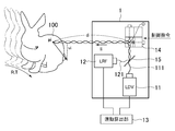
- the motion detection device 1 includes a speed detection unit 11, a distance detection unit 12, and a motion calculation unit 13 as main components (see FIG. 1). Furthermore, the motion detection apparatus 1 of the present embodiment additionally includes a direction control unit 14 and a dichroic mirror 15.
- the speed detection unit 11 is configured to irradiate the object 100 with the first laser beam 111. Further, the speed detection unit 11 is configured to receive the first laser beam 111 reflected from the object 100 and detect the speed of the object 100 using this. Specifically, a laser Doppler velocimeter (LDV) for detecting the moving speed of the object using the Doppler effect is used as the speed detection unit 11 of the present embodiment. When LDV is used, the moving speed of the object in the laser traveling direction is detected.
- LDV laser Doppler velocimeter
- the first laser beam 111 in the speed detector 11 has a wavelength that passes through the dichroic mirror 15.
- the distance detection unit 12 is configured to irradiate the second laser light 121 toward the object and detect the distance to the object 100 using the second laser light 121 reflected by the object 100. ing. Specifically, a laser range finder (LRF) that measures the flight time until the reflected light returns and measures the distance to the object is used as the distance detection unit 12 of the present embodiment.
- LRF laser range finder
- the second laser beam 121 in the distance detection unit 12 has a wavelength reflected by the dichroic mirror 15, and thereby the first laser beam 111 and the second laser beam 121 are substantially coaxial and coaxial with the object 100. Can be irradiated.
- the second laser beam 121 can be irradiated to the same position as the first laser beam 111 regardless of the position of the object 100. ing.
- first laser beam 111 and the second laser beam 121 have different wavelengths so that the wavelength can be separated by the dichroic mirror 15.
- the direction control unit 14 is configured to control the directions of the first laser beam 111 and the second laser beam 121.
- a so-called galvano scanner is used as the direction control unit 14 of the present embodiment.
- a galvano scanner is a device that can change the direction of light rays at high speed by changing the mirror angle.
- the direction control unit 14 according to the present embodiment can control the direction of the laser light by rotating the galvano mirror based on a control command from a control unit (not shown). As such a galvano scanner, since an existing one can be used, a detailed description thereof will be omitted.
- the direction control unit 14 of the present embodiment reflects the first laser beam 111 and the second laser beam 121 that are coaxial with each other by a mirror so that the angles of these laser beams coincide with each other.
- the laser beam can be irradiated toward the object 100.
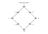
- the direction control section 14 of the present embodiment by changing the mirror angle at a high speed, the extent in the short time interval almost negligible movement of the object 100, so that it can irradiate a laser beam to a plurality of points p i It has become.
- FIG. 14 An example of the scanning pattern in the direction control unit 14 of this embodiment is shown in FIG.
- the direction control unit 14 of the present embodiment can irradiate a plurality of points p i for one cycle with laser light within a minute time interval.
- the moving speed between adjacent positions p i is increased while the moving speed of the laser at each position is temporarily set to 0 or low (that is, the laser beam irradiation time at that point is reduced). By increasing the length, the measurement accuracy can be improved.
- the motion calculation unit 13 detects the direction l i of the first laser beam 111 and the second laser beam 121 from the direction control unit 14 to the object 100, the speed v i obtained by the speed detection unit 11, and the distance detection.
- the information about the distance d i obtained by the unit 12 is used to calculate the motion about the object 100.
- the motion calculation unit 13 is configured to calculate a motion using information on the speed v i and the distance d i at a plurality of points p i on the object 100.
- the motion calculation unit 13 of the present embodiment is configured to calculate the rotation R and translation T of the object as motion.
- the motion calculation unit 13 of the present embodiment uses the information about the orientation l i of the first and second laser beams and the distance d i to perform the first and second lasers on the object 100.
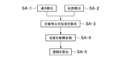
- Step SA-1 in FIG. 2 The object 100 is irradiated with the first laser beam 111 of the speed detection unit 11 via the dichroic mirror 15 and the direction control unit 14.
- the position and shape of the object 100 need not be known.
- the speed detector 11 can detect the speed of the object 100 by receiving the reflected light.
- the speed v i at the plurality of positions p i can be acquired by scanning the direction of the first laser light 111 based on the control signal to the direction control unit 14.
- the direction l i of the laser beam corresponding to the position p i or the speed v i is obtained by detecting the angle of the mirror in the direction control unit 14 or using the control instruction value to the direction control unit 14. Is possible.
- Step SA-2 in FIG. 2 On the other hand, the object 100 is irradiated with the second laser light 121 of the distance detection unit 12 via the dichroic mirror 15 and the direction control unit 14.
- the second laser beam 121 is overlapped with the first laser beam 111 by the dichroic mirror 15 to be coaxial. For this reason, according to this embodiment, even if the position and shape of the target object 100 are unknown, the first laser light 111 and the second laser light 121 are placed at the same position on the target object 100 at the same time. There is an advantage that it can be irradiated.
- the distance detection unit 12 can detect the distance from the distance detection unit 12 to the object 100 by receiving the reflected light.
- the distance from the direction control unit 14 specifically, the galvano mirror
- the distance from the direction control unit 14 is calculated by making the distance from the distance detection unit 12 to the direction control unit 14 known.
- the direction controller 14 scans the direction of the second laser beam 121 coaxially with the first laser beam 111, thereby obtaining the distance d i at the plurality of positions p i .
- the direction l i of the laser beam corresponding to the position p i is the same as in the case of the corresponding speed v i .
- Steps SA-3 and SA-4 in FIG. 2 the motion calculation unit 13 calculates a position p i on the object.
- the position p i irradiated with the laser beam can be calculated as the following formula (1) using the distance d i measured by the distance detection unit 12 and the known light direction l i .
- this position p i is converted into a position (position in a different coordinate system) q i based on the center of gravity of the measurement point p i for one cycle, as shown in the following formula (2).
- this q i is used to calculate exercise information.
- u i is a minute correction amount for correcting the offset accompanying the rotation of the galvanometer mirror.
- Step SA-5 in FIG. 2 The position q ′ of the measurement point a minute time ⁇ t after a certain measurement time satisfies the following equations (3) and (4). Therefore, the following equation (5) can be obtained by eliminating q ′ from both equations.
- R is a rotation matrix corresponding to the rotation of the object during the minute time ⁇ t
- T is a translation vector corresponding to translation.
- the rotation matrix R is expressed by the following equation (6) using the rotation angles ⁇ , ⁇ , and ⁇ corresponding to roll, bitch, and yaw. Can be approximated as follows.
- the motion x to be obtained can be expressed as a solution of the matrix equation of the following equation (7).
- a + is a pseudo inverse matrix of a coefficient matrix described later.
- the number n of unknowns is 6, it is assumed that the number of measurement points m is 6 or more.
- the present invention is not limited to this.
- the number of measurement points m can also be 5 or less. It is generally necessary that the number of measurement points when the position and shape of the object are unknown is larger than the number of unknowns. In general, increasing the number of measurement points increases the calculation cost, but increases the measurement accuracy. Below, the specific example of the solution of Formula (7) is demonstrated.
- Equation (7) is an inverse problem that reconstructs the three-dimensional motion of the entire object from the fragmentary motion information of each measurement point, it may be an inappropriate problem in which the stability of the solution cannot be obtained. There is sex.
- Tikhonov regularization is often used to take measures to stabilize the solution numerically.
- the solution x obtained in this example includes an angle parameter and a distance parameter in its elements. Then, in Tikhonov regularization using a single regularization parameter, it is difficult to properly regularize these two physical quantities.
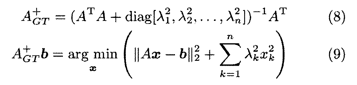
- Equation (8) shows a pseudo inverse matrix A + GT using generalized Tikhonov regularization.
- Equation (7) by solving Equation (7) using this A + GT , the rotation and translational motion of the object is calculated from the detection values v i and d i at the speed detection unit 11 and the distance detection unit 12. It can be performed.
- the motion calculation unit 13 of the present embodiment can calculate the motion of the object 100, specifically the rotation R and translation T thereof, by obtaining the solution x in the above selection.
- the three-dimensional motion (rotation and translation) of the object 100 can be detected without depending on the shape or pattern of the object. Therefore, the motion of an unknown object can be detected. Further, according to the apparatus of the present embodiment, even if the object is unintentionally huge, it is possible to detect the movement.
- the motion can be calculated using a calculation with low calculation cost, so that motion detection can be performed at high speed or in real time.
- the regularization parameter ⁇ k described above an optimum value can be obtained experimentally according to the system to be used.
- diag [6.0, 4.0, 4.0, 0.05, 0.05, 0.0] can be adopted as the minimum value that stabilizes the solution when the target is stationary while taking into account the difference in physical quantities, but is not limited to this.
- the wavelengths of the laser beams used by the distance detection unit 12 and the speed detection unit 11 can be set to, for example, 875 and 633 [nm], respectively.
- the angle ⁇ is about 10 °, for example, but is not limited thereto.
- the motion detection device of this embodiment can be used for tracking an object. That is, it is possible to continue measuring the movement of the object while detecting the movement of the object and tracking the object in the movement direction by the direction control unit 14.
- the motion detection device of this embodiment can be loaded on a moving body, and the relative motion of the environment relative to this device can be detected while moving.
- a moving body for example, an automobile or a train
- the shape of the tunnel wall surface and ceiling can be continuously inspected with high accuracy while moving in the tunnel by the moving body.
- the speed v i and the distance d i at the plurality of points p i are obtained by changing the direction of the laser beam at high speed using the direction control unit 14.
- the direction control unit 14 is omitted, and a plurality of detection units 17 are used instead.
- Each unit 17 includes a speed detector 11, a distance detector 12, and a dichroic mirror 15 (see FIG. 4).
- the number of units 17 corresponding to the number of measurement points (for example, 6) is used.
- This three-dimensional shape measurement apparatus further includes a shape detection unit 2 and a three-dimensional shape calculation unit 3 in addition to the motion detection device 1 described in the first embodiment.
- the shape detection unit 2 includes a line laser 21 and a camera 22.
- the line laser 21 is configured to irradiate the object 100 with laser light having a certain width.
- a line laser an existing one can be used, and a detailed description thereof will be omitted.
- the camera 22 can detect the shape of the line-shaped laser light projected on the surface of the object 100 in time series by photographing the object 100 at predetermined time intervals. Thereby, the shape detection part 2 of this embodiment becomes a structure which detects the shape in the specific time of the target object 100 in time series.
- the three-dimensional shape calculation unit 3 uses the information about the shape of the target object detected in time series (specifically, the shape of the photographed line) and the motion detected by the motion detection device 1. The three-dimensional shape of the object 100 is calculated. Detailed operation of the three-dimensional shape calculation unit 3 will be described later.
- the camera 22 captures the reflected light (having a line shape) of the laser light emitted from the line laser 21 onto the object 100, thereby obtaining the three-dimensional shape of the object 100 at the line position. Can be calculated based on the principle of triangulation. Such a method is also called a light cutting method.
- the method using a line laser has the advantage that the mounting is simple and cost reduction can be expected.
- the shape of the entire object is acquired by scanning a line laser.
- the target object 100 can be moved relatively with respect to a line laser by the target object 100 moving.
- a three-dimensional coordinate system with the optical center of the camera as the origin is considered, and the coordinate system is called a camera coordinate system.
- u t [u, v] T on the camera image at time t.
- x t [X, Y, Z] T be the position of this point in the camera coordinate system.
- the internal parameter P of the camera is set as follows.
- [o x , o y ] is the image center
- f is the focal length
- [k x , k y ] is the effective size of the image.
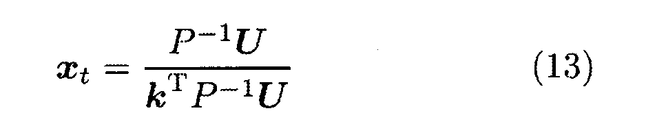
- xt is determined by the following equation according to the equations (11) and (12).
- the shape of the target object irradiated with the line laser light can be obtained as a three-dimensional point group by performing conversion to the same three-dimensional coordinates.
- the three-dimensional shape calculation unit 3 combines the three-dimensional point group (for example, a curve in the three-dimensional space) at a specific time obtained in this way with the motion information of the object by the alignment method described later, A three-dimensional shape can be calculated.
- the three-dimensional point ⁇ x t ⁇ c obtained in the camera coordinate system is converted into a three-dimensional point ⁇ x in the galvano coordinate system (a coordinate system having the origin near the mirror rotation center of the galvanometer mirror in the direction control unit 14).
- t ⁇ Convert to g .
- R cg and T cg obtained by calibration of camera coordinates and galvano coordinates
- the transformation of the coordinate system is expressed by the following equation (14).
- R cg is a rotation matrix from camera coordinates to galvano coordinates
- T cg is a translation vector from the origin of galvano coordinates to the origin of camera coordinates.
- the three-dimensional point ⁇ x t ⁇ g converted to the galvano coordinate system is expressed as x t for simplicity.
- the three-dimensional point group obtained at each time is aligned based on the position and orientation of the object at time 0.
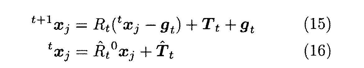
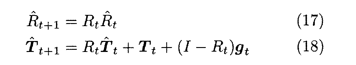
- the motion detection by the motion detection device 1 and the shape measurement frame rate by the shape detection unit 2 are assumed to be the same, and the rotational motion between time t and t +1 obtained by motion detection at time t,
- the translational and rotational centers are represented by R t , T t , and g t .
- the change in the object position and orientation from time 0 (see FIG. 6 (a)) to time t (see FIGS. 6 (b) and 6 (c)) is expressed by rotation and translation with the origin as the center of rotation.
- t hat, T t hat are aligned with reference to the position and orientation of an object in a three-dimensional point x t1 obtained at time t 1 at time t 2 and t2 x t1.
- a three-dimensional point 0 x t (see FIG. 6) based on the three-dimensional point t x t obtained at time t (see FIG. 6 (c)) based on the position and orientation of the object at time 0 (see FIG. 6 (a)). 6) (see (d)).
- First, using motion information R i , T i , g i (i 0, 1, ..., t -1) obtained from motion detection between time 0 and t – 1, time 0 to t Changes in the position and orientation of the target until R t hat and T t hat are calculated. Based on the R t hat and T t hat, the three-dimensional point t x t is aligned with 0 x t .
- the three-dimensional shape calculation unit 3 of the present embodiment can calculate the three-dimensional shape of the object 100 by performing the above-described calculation.
- the obtained three-dimensional shape can be output by an appropriate method.
- a display, a printer, a memory, another system, or the like can be appropriately set as necessary.
- the first laser beam and the second laser beam are separated by wavelength.
- both can be separated by time.
- the installation of the dichroic mirror 15 can be omitted.
- the wavelengths of the first laser beam and the second laser beam can be made the same.
- the position p i on the object is coordinate-transformed to q i in another coordinate system, which is the outer product (p i ⁇ l i ) T in equation (6).
- This is to avoid the calculation of the zero vector. That is, when the vector p i becomes parallel to the vector l i , their outer product becomes a zero vector, which hinders calculation. Therefore, any transformation may be used as long as it can avoid becoming a zero vector.
- the laser beam irradiation pattern described above is merely an example, and is not limited thereto. It is also possible to dynamically change the irradiation pattern according to the properties of the object.
- the components such as the motion calculation unit and the three-dimensional shape calculation unit described above may exist as function blocks, and may not exist as independent hardware.
- a mounting method hardware or computer software may be used.
- one functional element in the present invention may be realized by a set of a plurality of functional elements, and a plurality of functional elements in the present invention may be realized by one functional element.
- the functional elements may be arranged at physically separated positions.
- the functional elements may be connected by a network. It is also possible to realize functions or configure functional elements by grid computing or cloud computing.
Landscapes
- Physics & Mathematics (AREA)
- Engineering & Computer Science (AREA)
- General Physics & Mathematics (AREA)
- Electromagnetism (AREA)
- Radar, Positioning & Navigation (AREA)
- Remote Sensing (AREA)
- Computer Networks & Wireless Communication (AREA)
- Power Engineering (AREA)
- Length Measuring Devices By Optical Means (AREA)
- Measurement Of Optical Distance (AREA)
- Optical Radar Systems And Details Thereof (AREA)
Abstract
Description
速さ検出部と、距離検出部と、運動算出部とを備えており、
前記速さ検出部は、第1レーザ光を対象物に向けて照射し、かつ、前記対象物において反射された前記第1レーザ光を用いて、前記対象物の速さを検出する構成となっており、
前記距離検出部は、第2レーザ光を前記対象物に向けて照射し、かつ、前記対象物において反射された前記第2レーザ光を用いて、前記対象物までの距離を検出する構成となっており、
前記第2レーザ光は、前記第1レーザ光と実質的に同じタイミングでかつ同じ位置に照射される構成となっており、
前記運動算出部は、前記第1及び第2レーザ光の向きと、前記速さと、前記距離とについての情報を用いて、前記対象物についての運動を算出する構成となっている
ことを特徴とする運動検出装置。 (Item 1)
It has a speed detector, a distance detector, and a motion calculator,
The speed detector is configured to irradiate the first laser beam toward the object and detect the speed of the object using the first laser light reflected on the object. And
The distance detection unit is configured to irradiate the target with the second laser light and detect the distance to the target using the second laser light reflected on the target. And
The second laser light is configured to be irradiated at substantially the same timing and the same position as the first laser light,
The motion calculation unit is configured to calculate motion about the object using information about the directions of the first and second laser beams, the speed, and the distance. Motion detection device.
前記第1レーザ光と前記第2レーザ光とは、実質的に同軸で前記対象物に照射されている
項目1に記載の運動検出装置。 (Item 2)
The motion detection device according to
前記運動算出部は、前記対象物上での複数の点における前記速さ及び前記距離の情報を用いて前記運動を算出する構成となっている
項目1又は2に記載の運動検出装置。 (Item 3)
The motion detection device according to
前記対象物についての運動は、前記対象物の回転及び並進の運動である
項目1~3のいずれか1項に記載の運動検出装置。 (Item 4)
The motion detection device according to any one of
さらに方向制御部を備えており
前記方向制御部は、前記第1レーザ光及び前記第2レーザ光の向きを制御する構成となっている
項目1~4のいずれか1項に記載の運動検出装置。 (Item 5)
The motion detection device according to any one of
前記運動算出部は、前記第1及び第2レーザ光の向きと、前記距離とについての情報を用いて、前記対象物における前記第1及び第2レーザ光の照射位置pを算出し、前記照射位置pを、別の座標系における位置qに変換し、前記位置qと前記速さとを用いて前記対象物についての運動を算出する構成となっている
項目1~5のいずれか1項に記載の運動検出装置。 (Item 6)
The motion calculation unit calculates an irradiation position p of the first and second laser beams on the object using information on the directions of the first and second laser beams and the distance, and the
前記第1レーザ光と前記第2レーザ光とは、異なる波長とされている
項目1~6のいずれか1項に記載の運動検出装置。 (Item 7)
項目1~7のいずれか1項に記載の運動検出装置と、形状検出部と、三次元形状算出部とを備えており、
前記形状検出部は、前記対象物の特定時点における形状を時系列で検出する構成となっており、
前記三次元形状算出部は、前記時系列で検出された前記形状と前記運動とについての情報を用いて、前記対象物の三次元形状を算出する構成となっている
三次元形状測定装置。 (Item 8)
Comprising the motion detection device according to any one of
The shape detection unit is configured to detect the shape of the target object at a specific time point in time series,
The three-dimensional shape calculation unit is configured to calculate a three-dimensional shape of the object using information about the shape and the motion detected in the time series.
対象物に照射された第1レーザ光の反射光を用いて前記対象物の速さを検出するステップと、
前記対象物に照射された第2レーザ光の反射光を用いて前記対象物までの距離を検出するステップと、
前記第1レーザ光と前記第2レーザ光とにおける向きと、前記速さと、前記距離とについての情報を用いて、前記対象物についての運動を算出するステップと
を備える運動検出方法。 (Item 9)
Detecting the speed of the object using the reflected light of the first laser light applied to the object;
Detecting a distance to the object using a reflected light of the second laser light applied to the object;
A motion detection method comprising: calculating a motion of the object using information about an orientation in the first laser beam and the second laser beam, the speed, and the distance.
以下、本発明の第1実施形態に係る運動検出装置を、添付の図面を参照しながら説明する。 (First embodiment)
Hereinafter, a motion detection device according to a first embodiment of the present invention will be described with reference to the accompanying drawings.
本発明の第1実施形態に係る運動検出装置1は、速さ検出部11と、距離検出部12と、運動算出部13とを主要な構成として備えている(図1参照)。さらに、本実施形態の運動検出装置1は、方向制御部14とダイクロイックミラー15とを追加的に備えている。 (Configuration of the first embodiment)
The
速さ検出部11は、第1レーザ光111を対象物100に向けて照射する構成となっている。また、速さ検出部11は、対象物100において反射された第1レーザ光111を受光し、これを用いて対象物100の速さを検出する構成となっている。具体的には、本実施形態の速さ検出部11としては、ドップラ効果を用いて対象物の移動速度を検出するためのレーザドップラ速度計(LDV)が用いられている。LDVを用いるときは、レーザの進行方向における対象物の移動速度を検出していることになる。 (Speed detector)
The
距離検出部12は、第2レーザ光121を対象物に向けて照射し、かつ、対象物100において反射された第2レーザ光121を用いて、対象物100までの距離を検出する構成となっている。具体的には、本実施形態の距離検出部12としては、反射光が返ってくるまでの飛行時間を測定し、物体までの距離計測を行うレーザレンジファインダ(LRF)が用いられている。 (Distance detection unit)
The
方向制御部14は、第1レーザ光111及び第2レーザ光121の向きを制御する構成となっている。具体的には、本実施形態の方向制御部14としては、いわゆるガルバノスキャナが用いられている。ガルバノスキャナとは、ミラー角度を変更することで光線の方向を高速で変更することが可能な機器である。本実施形態の方向制御部14は、制御部(図示せず)からの制御指令に基づいてガルバノミラーを回動させることによって、レーザ光の方向を制御できるようになっている。このようなガルバノスキャナとしては、既存のものを利用可能なので、これについてのこれ以上詳しい説明は省略する。 (Direction control unit)
The
運動算出部13は、方向制御部14から対象物100への第1レーザ光111及び第2レーザ光121の向きliと、速さ検出部11で得られた速さviと、距離検出部12で得られた距離diという情報を用いて、対象物100についての運動を算出する構成となっている。ここで、運動算出部13は、対象物100上での複数の点piにおける速さvi及び距離diの情報を用いて運動を算出する構成となっている。 (Exercise calculation unit)
The
次に、前記した運動検出装置を用いた運動検出方法を、図3をさらに参照しながら説明する。 (Operation of the first embodiment)
Next, a motion detection method using the motion detection apparatus described above will be described with further reference to FIG.
速さ検出部11の第1レーザ光111を、ダイクロイックミラー15、方向制御部14を介して対象物100に照射する。なお、ここで、対象物100の位置や形状が既知である必要はない。 (Step SA-1 in FIG. 2)
The
一方、距離検出部12の第2レーザ光121を、ダイクロイックミラー15、方向制御部14を介して対象物100に照射する。第2レーザ光121は、ダイクロイックミラー15により、第1レーザ光111と重ね合わされて同軸とされる。このため、本実施形態によれば、対象物100の位置や形状が未知の場合であっても、第1レーザ光111と第2レーザ光121とを、対象物100における同じ位置に同時刻に照射することができるという利点がある。 (Step SA-2 in FIG. 2)
On the other hand, the
ついで、運動算出部13は、対象物上の位置piを算出する。ここで、レーザ光が照射された位置piは、距離検出部12により計測された距離di、既知の光線方向liを用いて、下記式(1)のように算出することができる。本実施形態では、この位置piを、下記式(2)に示すように、一周期分の計測点piの重心を基準とした位置(異なる座標系における位置)qiに変換する。本実施形態では、このqiを運動情報の算出に用いる。 (Steps SA-3 and SA-4 in FIG. 2)
Next, the

ある計測時刻から微小時間δt後の計測点の位置q'は、下記式(3)(4)を満たす。そこで、両式からq'を消去することで下記式(5)を得ることができる。ただし、Rは、微小時間δt間での対象物の回転に対応する回転行列、Tは、並進に対応する並進ベクトルである。 (Step SA-5 in FIG. 2)
The position q ′ of the measurement point a minute time δt after a certain measurement time satisfies the following equations (3) and (4). Therefore, the following equation (5) can be obtained by eliminating q ′ from both equations. Here, R is a rotation matrix corresponding to the rotation of the object during the minute time δt, and T is a translation vector corresponding to translation.

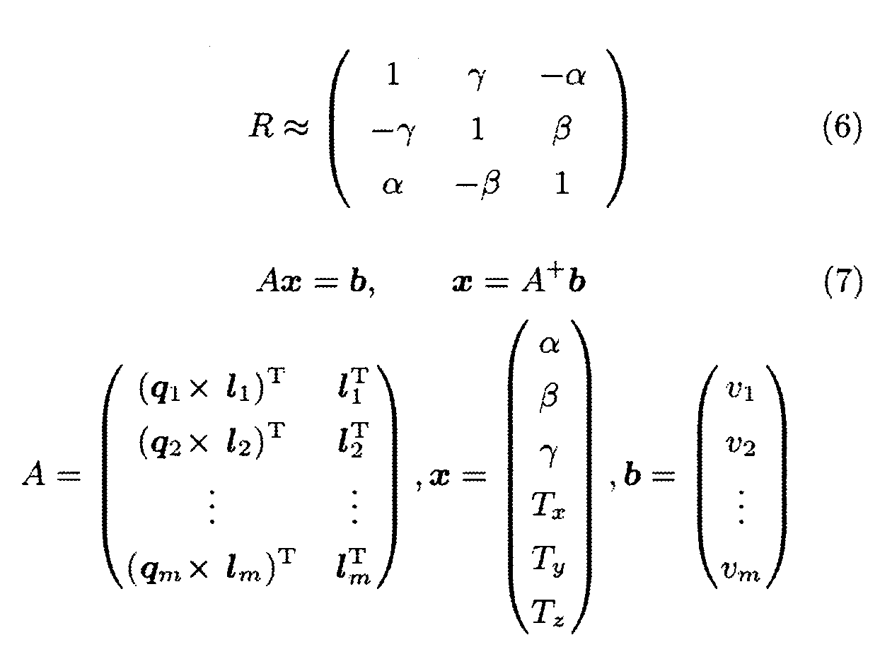
行列方程式Ax=bの解は一般的にMoore-Penroseの擬似逆行列を用いて表される。しかしながら、式(7)は、各計測点の断片的な運動情報から、対象全体の三次元運動を再構成する逆問題であるため、解の安定性が得られない非適切な問題となる可能性がある。このような問題に対しては、Tikhonovの正則化を用いて、解を数値的に安定化する対策がしばしば行われる。しかし、本例で求める解xは、その要素に角度のパラメータと距離のパラメータとを含んでいる。すると、単一の正則化パラメータを用いるTikhonov正則化では、これら二つの物理量を適切に正則化することは難しい。そこで、複数の物理量を含む問題に対応できるように拡張を行った一般化Tikhonov正則化を導入する。下記式(8)に、一般化Tikhonov正則化を用いた擬似逆行列A+ GTを示す。A+ GTはベクトルxの各要素に対応する正則化パラメータλk (k = 1, 2, .., n) を持っており、式(9)に示す重み付けユークリッド距離の意昧で最適なベクトルxを求めることができる。 本実施形態では、この A+ GTを用いて式(7)を解くことにより、速さ検出部11及び距離検出部12での検出値vi、diから対象物の回転及び並進運動の算出を行うことができる。 (Use of generalized Tikhonov regularization solution)
The solution of the matrix equation Ax = b is generally expressed using a Moore-Penrose pseudo-inverse matrix. However, since Equation (7) is an inverse problem that reconstructs the three-dimensional motion of the entire object from the fragmentary motion information of each measurement point, it may be an inappropriate problem in which the stability of the solution cannot be obtained. There is sex. For such problems, Tikhonov regularization is often used to take measures to stabilize the solution numerically. However, the solution x obtained in this example includes an angle parameter and a distance parameter in its elements. Then, in Tikhonov regularization using a single regularization parameter, it is difficult to properly regularize these two physical quantities. Therefore, we introduce generalized Tikhonov regularization that has been extended to deal with problems involving multiple physical quantities. The following equation (8) shows a pseudo inverse matrix A + GT using generalized Tikhonov regularization. A + GT has a regularization parameter λ k (k = 1, 2, .., n) corresponding to each element of the vector x, and is an optimal vector with the meaning of the weighted Euclidean distance shown in Equation (9). x can be obtained. In the present embodiment, by solving Equation (7) using this A + GT , the rotation and translational motion of the object is calculated from the detection values v i and d i at the
次に、図4をさらに参照して、本発明の第2実施形態に係る運動検出装置を説明する。なお、この第2実施形態の説明においては、前記した第1実施形態と基本的に共通する構成要素について、同一符号を付することにより、説明の煩雑を避ける。 (Motion detection device of the second embodiment)
Next, with reference further to FIG. 4, a motion detection apparatus according to a second embodiment of the present invention will be described. In the description of the second embodiment, components that are basically the same as those of the first embodiment described above are denoted by the same reference numerals, thereby avoiding complicated description.
次に、本発明の第3実施形態に係る三次元形状測定装置を、図5をさらに参照しながら説明する。なお、この第3実施形態の説明においては、前記した第1実施形態と基本的に共通する構成要素について、同一符号を付することにより、説明の煩雑を避ける。 (Third embodiment)
Next, a three-dimensional shape measuring apparatus according to a third embodiment of the present invention will be described with further reference to FIG. In the description of the third embodiment, components that are basically the same as those of the first embodiment described above are denoted by the same reference numerals, thereby avoiding complicated description.
形状検出部2は、ラインレーザ21と、カメラ22とを備えている。ラインレーザ21は、対象物100に対して、ある程度の幅を持つレーザ光を照射する構成となっている。このようなラインレーザとしては既存のものを利用可能なので、これについての詳しい説明は省略する。 (Configuration of Third Embodiment)
The
以下、第3実施形態に係る三次元形状測定装置を用いた測定方法について説明する。第3実施形態では、ラインレーザ21から対象物100に照射されたレーザ光の反射光(ライン状をなしている)をカメラ22によって撮影することで、ライン位置における対象物100の三次元形状を、三角測量の原理に基づいて計算することができる。このような手法は、光切断法とも呼ばれる。ラインレーザを用いる手法は、実装が簡易でありコスト低減が期待できるという利点がある。 (Operation of Third Embodiment)
Hereinafter, a measurement method using the three-dimensional shape measurement apparatus according to the third embodiment will be described. In the third embodiment, the
以下では、カメラの光学中心を原点とする三次元座標系を考え、その座標系をカメラ座標系とよぶ。今、ラインレーザ21から照射されたレーザ光(「ラインレーザ光」と称することがある)が照射された対象上の1点が時刻tのカメラ画像上で ut = [u, v]Tとして観測されたとする。この点のカメラ座標系での位置を xt = [X, Y, Z] Tとする。また、カメラの内部パラメータPを以下のように設定する。 (Principle of three-dimensional shape measurement)
In the following, a three-dimensional coordinate system with the optical center of the camera as the origin is considered, and the coordinate system is called a camera coordinate system. Now, one point on the target irradiated with the laser beam irradiated from the line laser 21 (sometimes referred to as “line laser beam”) is represented by u t = [u, v] T on the camera image at time t. Suppose that it was observed. Let x t = [X, Y, Z] T be the position of this point in the camera coordinate system. The internal parameter P of the camera is set as follows.


最初に、カメラ座標系において得られた三次元点 {xt}c をガルバノ座標系(方向制御部14におけるガルバノミラーのミラー回動中心付近を原点とした座標系)での三次元点 {xt}g に変換する。カメラ座標とガルバノ座標のキャリブレーションによって得られた Rcg, Tcg を用いて、座標系の変換は下記式(14)のように表される。ここでRcg は、カメラ座標からガルバノ座標への回転行列、Tcg は、ガルバノ座標の原点からカメラ座標の原点までの並進ベクトルである。 (Alignment method)
First, the three-dimensional point {x t } c obtained in the camera coordinate system is converted into a three-dimensional point {x in the galvano coordinate system (a coordinate system having the origin near the mirror rotation center of the galvanometer mirror in the


11 速さ検出部
111 第1レーザ光
12 距離検出部
121 第2レーザ光
13 運動算出部
14 方向制御部
15 ダイクロイックミラー
17 検出ユニット
2 形状検出部
21 ラインレーザ
22 カメラ
3 三次元形状算出部
100 対象物
di 距離
vi 速さ
li レーザ光の向き
pi レーザ光の照射位置
q pの座標変換により得た位置 DESCRIPTION OF
Claims (9)
- 速さ検出部と、距離検出部と、運動算出部とを備えており、
前記速さ検出部は、第1レーザ光を対象物に向けて照射し、かつ、前記対象物において反射された前記第1レーザ光を用いて、前記対象物の速さを検出する構成となっており、
前記距離検出部は、第2レーザ光を前記対象物に向けて照射し、かつ、前記対象物において反射された前記第2レーザ光を用いて、前記対象物までの距離を検出する構成となっており、
前記第2レーザ光は、前記第1レーザ光と実質的に同じタイミングでかつ同じ位置に照射される構成となっており、
前記運動算出部は、前記第1及び第2レーザ光の向きと、前記速さと、前記距離とについての情報を用いて、前記対象物についての運動を算出する構成となっている
ことを特徴とする運動検出装置。 It has a speed detector, a distance detector, and a motion calculator,
The speed detector is configured to irradiate the first laser beam toward the object and detect the speed of the object using the first laser light reflected on the object. And
The distance detection unit is configured to irradiate the target with the second laser light and detect the distance to the target using the second laser light reflected on the target. And
The second laser light is configured to be irradiated at substantially the same timing and the same position as the first laser light,
The motion calculation unit is configured to calculate motion about the object using information about the directions of the first and second laser beams, the speed, and the distance. Motion detection device. - 前記第1レーザ光と前記第2レーザ光とは、実質的に同軸で前記対象物に照射されている
請求項1に記載の運動検出装置。 The motion detection device according to claim 1, wherein the first laser beam and the second laser beam are substantially coaxially irradiated on the object. - 前記運動算出部は、前記対象物上での複数の点における前記速さ及び前記距離の情報を用いて前記運動を算出する構成となっている
請求項1又は2に記載の運動検出装置。 The motion detection device according to claim 1, wherein the motion calculation unit is configured to calculate the motion using information on the speed and the distance at a plurality of points on the object. - 前記対象物についての運動は、前記対象物の回転及び並進の運動である
請求項1~3のいずれか1項に記載の運動検出装置。 The motion detection device according to any one of claims 1 to 3, wherein the motion of the object is a rotational and translational motion of the object. - さらに方向制御部を備えており
前記方向制御部は、前記第1レーザ光及び前記第2レーザ光の向きを制御する構成となっている
請求項1~4のいずれか1項に記載の運動検出装置。 The motion detection according to any one of claims 1 to 4, further comprising a direction control unit, wherein the direction control unit is configured to control directions of the first laser beam and the second laser beam. apparatus. - 前記運動算出部は、前記第1及び第2レーザ光の向きと、前記距離とについての情報を用いて、前記対象物における前記第1及び第2レーザ光の照射位置pを算出し、前記照射位置pを、別の座標系における位置qに変換し、前記位置qと前記速さとを用いて前記対象物についての運動を算出する構成となっている
請求項1~5のいずれか1項に記載の運動検出装置。 The motion calculation unit calculates an irradiation position p of the first and second laser beams on the object using information on the directions of the first and second laser beams and the distance, and the irradiation 6. The structure according to claim 1, wherein the position p is converted into a position q in another coordinate system, and a motion about the object is calculated using the position q and the speed. The motion detection device described. - 前記第1レーザ光と前記第2レーザ光とは、異なる波長とされている
請求項1~6のいずれか1項に記載の運動検出装置。 The motion detection device according to any one of claims 1 to 6, wherein the first laser beam and the second laser beam have different wavelengths. - 請求項1~7のいずれか1項に記載の運動検出装置と、形状検出部と、三次元形状算出部とを備えており、
前記形状検出部は、前記対象物の特定時点における形状を時系列で検出する構成となっており、
前記三次元形状算出部は、前記時系列で検出された前記形状と前記運動とについての情報を用いて、前記対象物の三次元形状を算出する構成となっている
三次元形状測定装置。 A motion detection device according to any one of claims 1 to 7, a shape detection unit, and a three-dimensional shape calculation unit,
The shape detection unit is configured to detect the shape of the target object at a specific time point in time series,
The three-dimensional shape calculation unit is configured to calculate a three-dimensional shape of the object using information about the shape and the motion detected in the time series. - 対象物に照射された第1レーザ光の反射光を用いて前記対象物の速さを検出するステップと、
前記対象物に照射された第2レーザ光の反射光を用いて前記対象物までの距離を検出するステップと、
前記第1レーザ光と前記第2レーザ光とにおける向きと、前記速さと、前記距離とについての情報を用いて、前記対象物についての運動を算出するステップと
を備える運動検出方法。 Detecting the speed of the object using the reflected light of the first laser light applied to the object;
Detecting a distance to the object using a reflected light of the second laser light applied to the object;
A motion detection method comprising: calculating a motion of the object using information about an orientation in the first laser beam and the second laser beam, the speed, and the distance.
Priority Applications (4)
| Application Number | Priority Date | Filing Date | Title |
|---|---|---|---|
| CN201680050228.9A CN108027440A (en) | 2015-09-01 | 2016-08-26 | Motion detection apparatus and use its 3 d shape measuring apparatus |
| US15/756,959 US20180283851A1 (en) | 2015-09-01 | 2016-08-26 | Motion detection device and three-dimensional shape measurement device using same |
| EP16841691.5A EP3346287A4 (en) | 2015-09-01 | 2016-08-26 | Motion detection device and three-dimensional shape measurement device using same |
| JP2017537821A JPWO2017038659A1 (en) | 2015-09-01 | 2016-08-26 | Motion detection device and three-dimensional shape measurement device using the same |
Applications Claiming Priority (2)
| Application Number | Priority Date | Filing Date | Title |
|---|---|---|---|
| JP2015171785 | 2015-09-01 | ||
| JP2015-171785 | 2015-09-01 |
Publications (1)
| Publication Number | Publication Date |
|---|---|
| WO2017038659A1 true WO2017038659A1 (en) | 2017-03-09 |
Family
ID=58188835
Family Applications (1)
| Application Number | Title | Priority Date | Filing Date |
|---|---|---|---|
| PCT/JP2016/074907 WO2017038659A1 (en) | 2015-09-01 | 2016-08-26 | Motion detection device and three-dimensional shape measurement device using same |
Country Status (5)
| Country | Link |
|---|---|
| US (1) | US20180283851A1 (en) |
| EP (1) | EP3346287A4 (en) |
| JP (1) | JPWO2017038659A1 (en) |
| CN (1) | CN108027440A (en) |
| WO (1) | WO2017038659A1 (en) |
Families Citing this family (5)
| Publication number | Priority date | Publication date | Assignee | Title |
|---|---|---|---|---|
| CN110574357B (en) * | 2017-03-31 | 2021-10-22 | 索尼半导体解决方案公司 | Imaging control apparatus, method for controlling imaging control apparatus, and moving body |
| JP6968568B2 (en) * | 2017-04-20 | 2021-11-17 | 株式会社日立製作所 | Shape measurement system and shape measurement method |
| CN109171616A (en) * | 2018-08-07 | 2019-01-11 | 重庆金山医疗器械有限公司 | Obtain the system and method for 3D shape inside measured object |
| JP7078127B2 (en) * | 2018-10-18 | 2022-05-31 | 富士通株式会社 | Calculation method, calculation program and information processing equipment |
| US20210156881A1 (en) * | 2019-11-26 | 2021-05-27 | Faro Technologies, Inc. | Dynamic machine vision sensor (dmvs) that performs integrated 3d tracking |
Citations (8)
| Publication number | Priority date | Publication date | Assignee | Title |
|---|---|---|---|---|
| US4822164A (en) * | 1987-09-30 | 1989-04-18 | Eaton Corporation | Optical inspection device and method |
| JPH0592216A (en) * | 1991-09-30 | 1993-04-16 | Kawasaki Steel Corp | Coiling/uncoiling device |
| JP2000266851A (en) * | 1999-03-19 | 2000-09-29 | Minolta Co Ltd | Distance-measuring apparatus |
| JP2005502053A (en) * | 2001-09-04 | 2005-01-20 | ローズマウント エアロスペース インコーポレイテッド | System and method for measuring flow velocity in three axes |
| JP2008514967A (en) * | 2004-09-30 | 2008-05-08 | ファロ テクノロジーズ インコーポレーテッド | Absolute rangefinder to measure moving retroreflectors |
| JP2008516246A (en) * | 2004-10-13 | 2008-05-15 | ライカ・ゲオジステームス・アクチェンゲゼルシャフト | Method and apparatus for measuring absolute distance values |
| JP2009014701A (en) * | 2007-06-06 | 2009-01-22 | Yamatake Corp | Distance/speed meter, and distance/speed measuring method |
| JP2012518793A (en) * | 2009-02-20 | 2012-08-16 | デジタル・シグナル・コーポレーション | 3D image generation system and method using rider and video measurement |
Family Cites Families (8)
| Publication number | Priority date | Publication date | Assignee | Title |
|---|---|---|---|---|
| CN1021784C (en) * | 1990-06-28 | 1993-08-11 | 清华大学 | Measuring method for athletic posture and apparatus thereof |
| JP4142532B2 (en) * | 2003-09-02 | 2008-09-03 | シャープ株式会社 | Optical speedometer, displacement information measuring device, and conveyance processing device |
| CN1303433C (en) * | 2004-05-27 | 2007-03-07 | 中国科学院长春光学精密机械与物理研究所 | Double light path laser Doppler velocimeter capable of measuring speed for moving object of different distances |
| JP4888127B2 (en) * | 2007-01-17 | 2012-02-29 | コニカミノルタセンシング株式会社 | Three-dimensional measuring device and portable measuring instrument |
| JP5530069B2 (en) * | 2007-04-03 | 2014-06-25 | アズビル株式会社 | Distance / speed meter and distance / speed measurement method |
| KR20110018298A (en) * | 2008-04-30 | 2011-02-23 | 옵티칼 에어 데이터 시스템즈, 엘엘씨 | Laser doppler velocimeter |
| JP5633719B2 (en) * | 2009-09-18 | 2014-12-03 | 学校法人福岡工業大学 | 3D information measuring apparatus and 3D information measuring method |
| JP5114514B2 (en) * | 2010-02-25 | 2013-01-09 | 株式会社日立製作所 | Position estimation device |
-
2016
- 2016-08-26 JP JP2017537821A patent/JPWO2017038659A1/en active Pending
- 2016-08-26 US US15/756,959 patent/US20180283851A1/en not_active Abandoned
- 2016-08-26 WO PCT/JP2016/074907 patent/WO2017038659A1/en active Application Filing
- 2016-08-26 CN CN201680050228.9A patent/CN108027440A/en active Pending
- 2016-08-26 EP EP16841691.5A patent/EP3346287A4/en not_active Withdrawn
Patent Citations (8)
| Publication number | Priority date | Publication date | Assignee | Title |
|---|---|---|---|---|
| US4822164A (en) * | 1987-09-30 | 1989-04-18 | Eaton Corporation | Optical inspection device and method |
| JPH0592216A (en) * | 1991-09-30 | 1993-04-16 | Kawasaki Steel Corp | Coiling/uncoiling device |
| JP2000266851A (en) * | 1999-03-19 | 2000-09-29 | Minolta Co Ltd | Distance-measuring apparatus |
| JP2005502053A (en) * | 2001-09-04 | 2005-01-20 | ローズマウント エアロスペース インコーポレイテッド | System and method for measuring flow velocity in three axes |
| JP2008514967A (en) * | 2004-09-30 | 2008-05-08 | ファロ テクノロジーズ インコーポレーテッド | Absolute rangefinder to measure moving retroreflectors |
| JP2008516246A (en) * | 2004-10-13 | 2008-05-15 | ライカ・ゲオジステームス・アクチェンゲゼルシャフト | Method and apparatus for measuring absolute distance values |
| JP2009014701A (en) * | 2007-06-06 | 2009-01-22 | Yamatake Corp | Distance/speed meter, and distance/speed measuring method |
| JP2012518793A (en) * | 2009-02-20 | 2012-08-16 | デジタル・シグナル・コーポレーション | 3D image generation system and method using rider and video measurement |
Non-Patent Citations (1)
| Title |
|---|
| See also references of EP3346287A4 * |
Also Published As
| Publication number | Publication date |
|---|---|
| EP3346287A4 (en) | 2019-02-27 |
| US20180283851A1 (en) | 2018-10-04 |
| EP3346287A1 (en) | 2018-07-11 |
| JPWO2017038659A1 (en) | 2018-06-14 |
| CN108027440A (en) | 2018-05-11 |
Similar Documents
| Publication | Publication Date | Title |
|---|---|---|
| WO2017038659A1 (en) | Motion detection device and three-dimensional shape measurement device using same | |
| TWI624170B (en) | Image scanning system and method thereof | |
| EP3653989B1 (en) | Imaging device and monitoring device | |
| JP5587137B2 (en) | Measuring apparatus and measuring method | |
| JP6192853B2 (en) | Optical flow imaging system and method using ultrasonic depth detection | |
| JP5567908B2 (en) | Three-dimensional measuring apparatus, measuring method and program | |
| JP2016516196A (en) | Structured optical scanner correction tracked in 6 degrees of freedom | |
| JP6782903B2 (en) | Self-motion estimation system, control method and program of self-motion estimation system | |
| JP2011027623A (en) | Method and device of measuring position and posture | |
| JP2010530086A (en) | Imaging model and image processing apparatus | |
| JP6333396B2 (en) | Method and apparatus for measuring displacement of mobile platform | |
| JP2020042819A (en) | Method and apparatus for determining motion vector field, device, computer-readable storage medium, and vehicle | |
| WO2021174507A1 (en) | Parameter calibration method, device, and system, and storage medium | |
| US11729367B2 (en) | Wide viewing angle stereo camera apparatus and depth image processing method using the same | |
| Yang et al. | Accurate calibration approach for non-overlapping multi-camera system | |
| JP6410231B2 (en) | Alignment apparatus, alignment method, and computer program for alignment | |
| JP6042146B2 (en) | Object detection apparatus and object detection method | |
| Portugal-Zambrano et al. | Robust range finder through a laser pointer and a webcam | |
| CN108564626A (en) | Method and apparatus for determining the relative attitude angle being installed between the camera of acquisition entity | |
| KR102325121B1 (en) | Real-time robot position estimation metod through map information and image matching and the robot | |
| KR102106890B1 (en) | Mini Integrated-control device | |
| Shojaeipour et al. | Robot path obstacle locator using webcam and laser emitter | |
| KR102106889B1 (en) | Mini Integrated-control device | |
| KR101436097B1 (en) | Non-Contacting Method for Measuring 6-DOF Motion Based on Laser Sensor | |
| JP6237117B2 (en) | Image processing apparatus, robot system, image processing method, and image processing program |
Legal Events
| Date | Code | Title | Description |
|---|---|---|---|
| 121 | Ep: the epo has been informed by wipo that ep was designated in this application |
Ref document number: 16841691 Country of ref document: EP Kind code of ref document: A1 |
|
| ENP | Entry into the national phase |
Ref document number: 2017537821 Country of ref document: JP Kind code of ref document: A |
|
| WWE | Wipo information: entry into national phase |
Ref document number: 15756959 Country of ref document: US |
|
| NENP | Non-entry into the national phase |
Ref country code: DE |
|
| WWE | Wipo information: entry into national phase |
Ref document number: 2016841691 Country of ref document: EP |