WO2017033457A1 - Heat cooking device - Google Patents
Heat cooking device Download PDFInfo
- Publication number
- WO2017033457A1 WO2017033457A1 PCT/JP2016/003816 JP2016003816W WO2017033457A1 WO 2017033457 A1 WO2017033457 A1 WO 2017033457A1 JP 2016003816 W JP2016003816 W JP 2016003816W WO 2017033457 A1 WO2017033457 A1 WO 2017033457A1
- Authority
- WO
- WIPO (PCT)
- Prior art keywords
- memory card
- heating
- card
- mounting mechanism
- machine room
- Prior art date
Links
Images


Classifications
-
- H—ELECTRICITY
- H05—ELECTRIC TECHNIQUES NOT OTHERWISE PROVIDED FOR
- H05B—ELECTRIC HEATING; ELECTRIC LIGHT SOURCES NOT OTHERWISE PROVIDED FOR; CIRCUIT ARRANGEMENTS FOR ELECTRIC LIGHT SOURCES, IN GENERAL
- H05B6/00—Heating by electric, magnetic or electromagnetic fields
- H05B6/64—Heating using microwaves
- H05B6/6435—Aspects relating to the user interface of the microwave heating apparatus
- H05B6/6441—Aspects relating to the user interface of the microwave heating apparatus allowing the input of coded operation instructions, e.g. bar code reader
-
- F—MECHANICAL ENGINEERING; LIGHTING; HEATING; WEAPONS; BLASTING
- F24—HEATING; RANGES; VENTILATING
- F24C—DOMESTIC STOVES OR RANGES ; DETAILS OF DOMESTIC STOVES OR RANGES, OF GENERAL APPLICATION
- F24C7/00—Stoves or ranges heated by electric energy
- F24C7/08—Arrangement or mounting of control or safety devices
- F24C7/082—Arrangement or mounting of control or safety devices on ranges, e.g. control panels, illumination
- F24C7/085—Arrangement or mounting of control or safety devices on ranges, e.g. control panels, illumination on baking ovens
-
- H—ELECTRICITY
- H05—ELECTRIC TECHNIQUES NOT OTHERWISE PROVIDED FOR
- H05B—ELECTRIC HEATING; ELECTRIC LIGHT SOURCES NOT OTHERWISE PROVIDED FOR; CIRCUIT ARRANGEMENTS FOR ELECTRIC LIGHT SOURCES, IN GENERAL
- H05B6/00—Heating by electric, magnetic or electromagnetic fields
- H05B6/64—Heating using microwaves
- H05B6/6426—Aspects relating to the exterior of the microwave heating apparatus, e.g. metal casing, power cord
-
- H—ELECTRICITY
- H05—ELECTRIC TECHNIQUES NOT OTHERWISE PROVIDED FOR
- H05B—ELECTRIC HEATING; ELECTRIC LIGHT SOURCES NOT OTHERWISE PROVIDED FOR; CIRCUIT ARRANGEMENTS FOR ELECTRIC LIGHT SOURCES, IN GENERAL
- H05B6/00—Heating by electric, magnetic or electromagnetic fields
- H05B6/64—Heating using microwaves
- H05B6/6435—Aspects relating to the user interface of the microwave heating apparatus
-
- F—MECHANICAL ENGINEERING; LIGHTING; HEATING; WEAPONS; BLASTING
- F24—HEATING; RANGES; VENTILATING
- F24C—DOMESTIC STOVES OR RANGES ; DETAILS OF DOMESTIC STOVES OR RANGES, OF GENERAL APPLICATION
- F24C15/00—Details
- F24C15/006—Arrangements for circulation of cooling air
Definitions
- the present disclosure relates to a heating cooker that performs microwave heating by microwave irradiation on an object to be heated, and in particular, a commercial heating cooker used as a heating cooker in a commercial facility such as a convenience store or a fast food store. About.
- the following configurations are used so as to be compatible with various menus. That is, in addition to the microwave heating mode in which the object to be heated is cooked by microwave irradiation, the grill mode in which the object to be heated is cooked by radiant heating using a heater, and the air heated by the heater is used using a fan.
- a configuration having a convection mode in which an object to be heated is cooked by convection in a heating chamber is used.
- the processing conditions in each heating process are preset, and the set processing conditions are configured to be stored in a storage medium provided in the commercial heating cooker. Therefore, in each store, it is possible to perform cooking using exactly the same processing conditions for the same menu according to the customer's order by using a commercial cooking device equipped with a storage medium. Become.
- the commercial cooking device is provided with a storage medium that stores the processing conditions of each cooking so as to be compatible with various menus.
- a storage medium that stores the processing conditions of each cooking so as to be compatible with various menus.
- an exchangeable memory card is used as a storage medium because it is necessary to change the processing conditions in each heating step each time the menu changes. Therefore, by changing the memory card, it is possible to easily cope with menu changes and the like (for example, see Patent Document 1).
- the commercial heating cooker is always activated so that it can respond quickly to customer orders, so the cooling fan is operating and the heating chamber is preheated.
- the commercial heating cooker is installed near water such as a kitchen in a store or the like, it is assumed that the entire device is splashed with water during cooking and cleaning, and waterproofing measures are also required.
- a structure that does not allow foreign matters such as dust to enter and a heat insulating structure that is not exposed to high temperatures is required. For this reason, in the conventional cooker for business use, in order to provide the mounting mechanism for mounting the memory card, a special member is required, and it is necessary to secure a large space.
- the card insertion slot for inserting the memory card is provided on the front side of the commercial heating cooker, it is necessary to provide an exterior plate for covering the card insertion slot.
- an exterior plate is provided to cover the card slot, a mark is required to clearly indicate that the card slot is covered, and the customer may be injured if they touch the exterior plate. It was necessary to process the edge of the exterior plate smoothly so that there was no problem. As a result, the conventional cooking device for business use has a problem that the number of work steps in parts production increases and the manufacturing cost becomes high.
- the memory card is a configuration that can be exchanged for a user who is an employee of a store or the like, and a configuration that cannot be easily accessed by a third party. It is also essential in terms of information leakage.
- the mechanism to which the memory card is attached has a configuration that cannot be easily visually recognized in appearance, and a configuration that cannot be easily accessed by a third party. Yes.
- the memory card can be installed in a mechanism that prevents dust and other foreign matter from entering it and is not exposed to high temperatures, and does not require special waterproofing measures.
- a heating cooker includes a main body having a heating chamber for storing and heating an object to be heated, and a microwave disposed in the lower side of the main body for microwave heating in the heating chamber.
- a machine room provided with a mechanism for forming and transmitting, a front grille panel detachably attached to the front surface of the machine room, a door configured to be openable and closable with respect to the heating chamber, and a main body
- a memory card mounting mechanism for mounting the memory card.
- the memory card mounting mechanism has a card insertion slot for inserting a memory card on the lower surface of the main body, and is configured to insert the memory card vertically above the card insertion slot.
- the card insertion slot is configured not to appear on the appearance of the cooking device by a front grille panel mounted in the machine room.
- the memory card mounting mechanism has a configuration that cannot be easily visually recognized in appearance, and cannot be easily accessed by a third party. Therefore, it is possible to provide a highly reliable commercial cooking device that does not require special waterproofing measures.
- Drawing 1 is a perspective view showing the state where the door of the cooking-by-heating machine concerning an embodiment of this indication was closed.
- Drawing 2 is a perspective view showing the state where the door of the cooking-by-heating machine concerning an embodiment of this indication opened.
- FIG. 3 is a cross-sectional view illustrating a state where the right side surface of the heating cooker according to the embodiment of the present disclosure is removed.
- Drawing 4 is a perspective view which looked at a cooking-by-heating machine concerning an embodiment of this indication from diagonally right above.
- Drawing 5 is a perspective view which looked at a cooking-by-heating machine concerning an embodiment of this indication from the right slanting lower part.
- FIG. 7 is an enlarged view of the memory card mounting mechanism in the cooking device shown in FIG.
- FIG. 8 is a diagram illustrating a state in which a memory card is mounted on the memory card mounting mechanism illustrated in FIG.
- FIG. 9 is a side cross-sectional view of the memory card mounting mechanism in the cooking device according to the embodiment of the present disclosure.
- FIG. 10 is a side cross-sectional view of the memory card mounting mechanism in the cooking device according to the embodiment of the present disclosure.
- a heating cooker includes a main body having a heating chamber for storing and heating an object to be heated, a micro that is disposed on the lower side of the main body, and is used for microwave heating in the heating chamber.
- a machine room provided with a mechanism for forming and transmitting a wave; a front grille panel detachably attached to the front surface of the machine room; and a door configured to be openable and closable with respect to the heating room;
- a memory card mounting mechanism for mounting the memory card on the main body.
- the memory card mounting mechanism has a card insertion slot for inserting a memory card on the lower surface of the main body, and is configured to insert the memory card vertically above the card insertion slot.
- the card insertion slot is configured not to appear on the appearance of the cooking device by a front grille panel mounted in the machine room.
- the heating cooker according to the first aspect of the present disclosure configured as described above has a configuration in which the memory card mounting mechanism cannot be easily visually recognized in appearance and cannot be easily accessed by a third party. Furthermore, it is possible to provide a highly reliable commercial cooking device that does not require any special waterproofing measures.
- the card insertion slot of the memory card mounting mechanism according to the first aspect is provided on the lower surface of the operation unit provided on the front surface of the main body, and is mounted on the memory card mounting mechanism.
- the configured memory card is configured to be accommodated inside the operation unit.
- the operation unit itself has a structure insulated from the heating chamber, and there are also parts that generate high heat inside the operation unit. not exist. Furthermore, since the inside of the operation unit is not a ventilation path by a cooling fan or the like, the contamination of foreign matters such as dust is greatly reduced. For this reason, in the configuration of the heating cooker according to the second aspect of the present disclosure, it is not necessary to provide a special heat insulating structure in the memory card mounting mechanism, and a special structure for preventing contamination such as dust There is no need to provide. Furthermore, in the configuration of the heating cooker according to the second aspect of the present disclosure, the wiring path between the memory card mounting mechanism and the electric circuit board in the operation unit is shortened, and the influence of noise in the wiring path is greatly reduced. can do.
- a card cover that covers the card insertion slot in the second aspect from the lower side is provided rotatably.
- a heating cooker according to a fourth aspect of the present disclosure is an electric circuit in which a flat surface of a memory card attached to a memory card attachment mechanism is provided inside the operation unit in the operation unit according to the third aspect. It is comprised so that it may become parallel with the mounting surface of a board
- the configuration in the operation unit can be simplified, and the necessary space in the operation unit is reduced.
- a heating cooker includes a cooling fan for cooling the mechanism in the machine room according to the fourth aspect, through an outside air inlet formed in the front surface of the machine room through the front grille panel.
- the outside air is configured to be sucked into the machine room.
- the memory card mounting mechanism is arranged off the outside air inflow path by the cooling fan.
- the memory card mounting mechanism is removed from the outside air inflow path and is not present in the path through which air flows. For this reason, possibility that foreign materials, such as dust, will enter will be reduced greatly, and it will become a reliable cooking device.
- a microwave oven as a microwave heating apparatus capable of executing the microwave heating, the grill mode, and the convection mode is used as an embodiment according to the cooking device of the present disclosure.
- a cooking device that is a commercial microwave oven used in stores, particularly convenience stores and fast food stores will be described with reference to the accompanying drawings. Note that the cooking device of the present disclosure is not limited to the configuration of the commercial microwave oven described in the following embodiment, but the technical idea equivalent to the technical idea described in the following embodiment. The structure of the heating cooker based on is included.
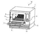
- FIG. 1 is a perspective view showing an appearance of a heating cooker 10 according to an embodiment of the present disclosure, and shows a state where a door formed on the front surface of the heating cooker 10 is closed.
- FIG. 2 shows a state in which the door in the heating cooker 10 shown in FIG. 1 is opened and the heating chamber formed inside the heating cooker 10 is opened.
- the heating cooker 10 is a microwave oven for business use particularly in stores such as convenience stores and fast food restaurants, and has a configuration capable of switching outputs in a plurality of stages with a maximum output of 1200 W to 1300 W. Have.
- the heating cooker 10 includes a main body 1 constituting an outer box of the heating chamber, and a machine room 2 provided below the main body 1 so as to support the main body 1. And a door 3 attached to the front side of the main body 1.
- a removable front grille panel 12 is provided on the front side of the machine room 2.
- a heating chamber 4 is formed inside the main body 1.
- the heating chamber 4 is a substantially rectangular parallelepiped space having an opening on the front side (door side) in order to accommodate an object to be heated therein.
- the side on which the opening of the heating chamber 4 is formed is defined as the front side of the heating cooker 10
- the back side of the heating chamber 4 is defined as the rear side of the heating cooker 10
- the heating cooker 10 is defined as the front side.
- the right side of the heating cooker 10 viewed from the right is simply referred to as the right side
- the left side of the heating cooker 10 viewed from the front is simply referred to as the left side.
- the door 3 is attached to the front side of the main body 1 so as to be openable and closable by vertically opening so as to close the opening in front of the heating chamber 4.
- a user grips a handle 5 provided on the door 3 so that the door 3 can be opened and closed.
- the inside of the heating chamber 4 is a sealed space in which a heat treatment using microwaves or the like is performed on the object to be heated.
- the door 3 shown in FIG. 2 is opened, the user puts an object to be heated into and out of the heating chamber 4.
- an operation unit 6 is provided on the front right side of the main body 1, and the operation unit 6 is used to set and operate the cooking conditions for the heating cooker 10. Buttons and display screens are provided.
- a ceramic (specifically, cordierite) tray 7 and a stainless steel wire rack 8 are disposed inside the heating chamber 4 so as to be accommodated.
- the wire rack 8 is a placement portion made of a net-like member for placing an object to be heated.
- the tray 7 is provided below the wire rack 8 and is disposed so as to receive a fat or the like dripping from an object to be heated on the wire rack 8.
- the machine room 2 below the heating chamber 4 is provided with a magnetron that is a microwave generation unit.
- the microwave from the magnetron is configured to be radiated from the microwave radiation hole formed in the waveguide and the opening formed on the bottom surface side of the heating chamber 4 through the waveguide.
- emitted in the inside of the heating chamber 4 from the microwave radiation hole of a waveguide and the opening formed in the bottom face of the heating chamber 4 is stirred with a stirrer (stirrer).
- the object to be heated accommodated in the heating chamber 4 is heated by the microwave by the heating cooker configured as described above.
- the grill heater comprised with the sheathed heater is provided in the ceiling side of the heating chamber 4, and the inside of the heating chamber 4 is heated with the radiant heat from a grill heater. The object is directly heated and the grill mode is executed.
- a convection device for supplying hot air to the inside of the heating chamber 4 is provided behind the back wall of the heating chamber 4.
- the convection device has a function of sucking air inside the heating chamber 4, heating the sucked air, and blowing it out as hot air into the heating chamber 4.
- a circulating flow by the hot air is generated inside the heating chamber 4.
- the convection device sucks in from the central region of the heating chamber 4, heats the sucked air, blows it out from the front side of the bottom surface or / and the front side of the ceiling into the heating chamber 4, and circulates hot air.
- the heating by the microwave from the magnetron which is the microwave generating unit, the heating by the radiation using the grill heater on the upper side of the heating chamber 4, and the convection device It is the structure which can be performed separately or simultaneously with the heating by the circulating flow of hot air using.
- the heating cooker 10 has a configuration in which a heater that is a large heat source is not disposed below an object to be heated housed in a heating chamber. For this reason, it becomes a highly safe cooking device in which liquids such as oils dripping from the object to be heated do not come into contact with the heater and smoke or ignition does not occur.
- a magnetron as a microwave generation unit for generating a microwave
- an inverter device for driving the magnetron
- a cooling fan for cooling the magnetron and the inverter device, and the like.
- the total output is 1200 W to 1300 W.
- the microwaves output from the two magnetrons are transmitted through the two waveguides, and the microwave radiation openings formed in the respective waveguides and the openings formed in the bottom surface of the heating chamber 4 are transmitted. And then radiated into the heating chamber, stirred by the stirrer and radiated into the heating chamber 4.
- the inverter device drives a magnetron, and two inverter devices are provided in the machine room to drive two magnetrons.
- a plurality of cooling fans for cooling each of the magnetron and the inverter device are disposed in the machine room 2.
- four cooling fans are provided, and each cooling fan sucks outside air from the front grill panel 12 provided on the front surface of the machine room 2 and sends the sucked outside air to the rear.
- the inverter devices and magnetrons arranged in a row are cooled in order.
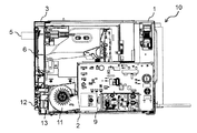
- FIG. 3 is a cross-sectional view showing a state where the right side surface of the heating cooker 10 according to the present embodiment is removed.
- a cooling fan 11 is disposed on the front side of the machine room 2, and when the cooling fan 11 is activated, air is sucked from a front grill panel 12 provided on the front surface of the machine room 2, thereby cooling the fan.
- the power supply circuit board 9 disposed behind 11 is cooled. The magnetron, the inverter device, the waveguide, and the like provided in the machine room 2 are hidden by the power supply circuit board 9 and the cooling fan 11 shown in FIG.
- the four cooling fans arranged in parallel for cooling the heat generating portions such as the inverter device and the magnetron, and the cooling fan 11 for cooling the power supply circuit board are constituted by a multiblade fan or the like. .
- These cooling fans are installed so that the respective rotating shafts are arranged in a straight line, and take in air from the axial direction of the rotating shaft and send out air toward the rear of the machine chamber 2 in the outer peripheral direction.
- the air that flows backward in the machine room 2 passes through the exhaust duct disposed on the back surface of the main body 1, passes between the ceiling wall of the heating chamber 4 and the top wall of the main body 1, and is discharged from the front side of the main body 1. It has a structure. In this way, by flowing the air from the cooling fan, the upper surface wall of the back wall of the main body 1 is prevented from becoming hot.
- the commercial cooking device configured as described above is provided with a memory card mounting mechanism for mounting a small memory card, for example, an SD card, which stores various cooking conditions.
- a memory card mounting mechanism for mounting a small memory card, for example, an SD card, which stores various cooking conditions.
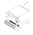
- FIG. 4 and FIG. 5 are perspective views showing the commercial cooking device 10 of the present embodiment, and show a state where the front grill panel 12 provided on the front side of the machine room 2 is removed.
- 4 is a perspective view seen from the upper right
- FIG. 5 is a perspective view seen from the lower right.
- the front grille panel 12 constituting the front side lower appearance of the heating cooker 10 is configured to be detachable from the machine room 2.
- On the front surface of the front grille panel 12 a plurality of plate members that are inclined downward so as to take in the outside air from below are arranged vertically with a predetermined gap.
- An outside air suction port 13 having a plurality of punching holes is formed in the front surface of the machine room 2 from which the front grille panel 12 is removed.
- four cooling fans for cooling the inverter device, the magnetron and the like, and a cooling fan 11 for cooling the power supply circuit board are arranged in parallel on the rear side of the outside air inlet 13. ing.
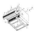
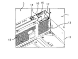
- FIG. 6 is a view of the state where the front grill panel 12 is removed from the heating cooker 10 as viewed obliquely from below.
- a memory card mounting mechanism 15 is provided below the operation unit 6 on the right front surface of the main body 1.
- the front grill panel 12 is disposed immediately below the operation unit 6 and the door 3, so that the memory card mounting mechanism 15 appears on the appearance of the heating cooker. It cannot be put out and cannot be visually recognized.
- the memory card loading mechanism 15 is loaded with an SD card 14 which is a small memory card.
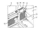
- FIG. 7 is an enlarged view of the memory card mounting mechanism 15 shown in FIG. FIG. 7 shows a state immediately before the SD card 14 is inserted into the card insertion slot 16 of the memory card mounting mechanism 15.
- the memory card mounting mechanism 15 is provided with a card insertion slot 16 for inserting the SD card 14 upward, and the card insertion slot 16 is provided on the lower surface of the operation unit 6.
- FIG. 8 shows a state in which the SD card 14 is installed in the card insertion slot 16 of the memory card installation mechanism 15.
- the SD card 14 is inserted by slightly protruding from the card insertion slot 16, but since the periphery of the card insertion slot 16 is formed with a recess, the protruding part of the SD card 14 is It is surrounded by a recess. Therefore, when the SD card 14 is mounted on the memory card mounting mechanism 15, the SD card 14 does not substantially protrude from the lower surface of the operation unit 6.
- the memory card mounting mechanism 15 in the present embodiment is provided with a card cover 17 that is mounted so as to cover the SD card 14 after the SD card 14 is mounted.
- the card cover 17 is fixed to the memory card mounting mechanism 15 by a fixing means that can be easily attached and detached, for example, a screw 18, and covers the card insertion slot 16 into which the SD card 14 is mounted from the lower side, and is securely sealed. Therefore, the SD card 14 is prevented from being easily accessed and removed, and the card insertion slot 16 is reliably prevented from being mixed with foreign matter such as dust.
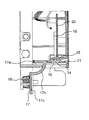
- FIG. 9 is a side cross-sectional view of the memory card mounting mechanism 15 in the present embodiment, and is a view of the SD card 14 mounted on the memory card mounting mechanism 15 as viewed from the left side.
- the state shown in FIG. 9 is a state before the SD card 14 is attached to the memory card attachment mechanism 15 and the card cover 17 is attached.
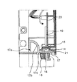
- the state shown in the side sectional view of FIG. 10 shows a state in which the card cover 17 is attached to the memory card mounting mechanism 15 from the state of FIG.
- the card cover 17 in the present embodiment is configured to be rotatable about a hinge 17a.
- the card cover 17 has a curved portion 17b formed so as to bypass a part of the casing at the lower end (lower surface) of the operation portion 6, and a fixing portion 17c that covers and seals the card insertion slot 16 from below. is doing.
- the fixing portion 17c of the card cover 17 is provided with a screw 18 that is a fixing means, and the fixing portion 17c is configured to securely cover the card insertion slot 16 of the memory card mounting mechanism 15.
- the memory card mounting mechanism 15 in the present embodiment includes a bottom wall 21 of the operation unit 6 in which a card insertion slot 16 is formed, and an SD card connector 19 into which the SD card 14 is inserted and electrically connected to a control circuit. And a base 20 for holding the SD card connector 19 in the internal space of the operation unit 6.
- the card cover 17 is attached to the lower surface wall 21 of the operation unit 6 in which the card insertion slot 16 is formed, and constitutes a substantial lower surface of the operation unit 6.
- the mounting surface of the base 20 to which the SD card connector 19 is fixed is such that the insertion direction of the SD card connector 19 is vertically upward. In the internal space of 6, it is a vertical surface. Further, the SD card connector 19 is arranged so that the flat surface of the mounted SD card 14 is parallel to the mounting surface (flat surface) of the electric circuit board (control circuit board) disposed inside the operation unit 6.
- the configuration is fixed to the base 20. Therefore, the SD card connector 19 can be disposed in the operation unit 6 using the base 20 in the same manner as other electric circuit boards, and no special disposing member is required. Can be used effectively. Furthermore, in the commercial cooking device of the present embodiment, the space for providing the memory card mounting mechanism 15 can be reduced, and the configuration contributes to downsizing of the entire apparatus.
- the internal space of the operation unit 6 has a predetermined space with respect to the heating chamber 4 and is disposed via a heat insulating member, and is not provided with a member that generates heat at a high temperature. 19 is not exposed to high temperatures. Further, since there is no member that generates large noise in the internal space of the operation unit 6 and the wiring distance from the SD card connector 19 to the control circuit is short, information acquisition from the SD card 14 mounted on the memory card mounting mechanism 15 is obtained. In this configuration, there is less fear of malfunction.
- the front grill panel 12 in which the memory card mounting mechanism having the card insertion slot 16 into which the memory card is mounted is detachably attached to the front side of the machine room 2. It is the structure which cannot be visually recognized from the external appearance of a cooking-by-heating machine. Therefore, when replacing the memory card, it is necessary to remove the front grille panel 12, remove the card cover 17 provided on the lower surface side of the operation unit 6, and open the card insertion slot 16.
- the card insertion slot 16 is provided on the lower surface of the operation unit 6, and is configured to insert a memory card vertically upward from the card insertion slot 16 and to attach the memory card to the memory card insertion mechanism. Accordingly, the card insertion slot 16 is surrounded by a recess in the lower surface wall 21 of the operation unit 6 and is disposed downward, and thus has a structure that prevents moisture from entering through the card insertion slot 16.
- the card insertion slot 16 and the memory card connector (SD card connector 19) do not require a waterproof structure.
- the card insertion slot is not provided so as to be exposed to the front side as in the conventional commercial heating cooker. There is no need to provide an exterior plate for covering, and naturally there is no processing of the exterior plate, so there is no problem of increasing the number of work steps in parts production.
- the memory card mounting mechanism has an external configuration that does not appear and is not visible in the external appearance, and has a structure that a third party cannot easily access. Have.
- the commercial cooking device of the present embodiment has a configuration in which foreign matters such as dust are difficult to enter and are not exposed to high temperatures.
- the commercial heating cooker according to the present embodiment has a configuration that does not require any special waterproofing measures, and has a simple configuration and high reliability.
- the present disclosure is a configuration applicable to a heating cooker that heats and cooks an object to be heated, and is particularly useful in a heating cooker such as a commercial microwave oven used in a convenience store or a fast food store. It is.
Landscapes
- Engineering & Computer Science (AREA)
- Physics & Mathematics (AREA)
- Electromagnetism (AREA)
- Human Computer Interaction (AREA)
- Chemical & Material Sciences (AREA)
- Combustion & Propulsion (AREA)
- Mechanical Engineering (AREA)
- General Engineering & Computer Science (AREA)
- Electric Ovens (AREA)
Abstract
Description
上記のように構成された業務用の加熱調理器においては、各種加熱調理の処理条件を記憶した小型のメモリーカード、例えばSDカードを装着するためのメモリーカード装着機構が設けられている。 [Memory card loading mechanism]
The commercial cooking device configured as described above is provided with a memory card mounting mechanism for mounting a small memory card, for example, an SD card, which stores various cooking conditions.
2 機械室
3 扉
4 加熱室
5 把手
6 操作部
7 トレイ
8 ワイヤラック
9 電源回路基板
10 加熱調理器
11 冷却ファン
12 フロントグリルパネル
13 外気吸込口
14 SDカード
15 メモリーカード装着機構
16 カード挿入口
17 カードカバー
18 固定手段(ネジ)
19 SDカードコネクタ
20 基台 DESCRIPTION OF
19
Claims (5)
- 被加熱物を収容して加熱するための加熱室を有する本体と、
前記本体の下側に配設され、前記加熱室においてマイクロ波加熱するためのマイクロ波を形成して伝送するための機構が設けられた機械室と、
前記機械室の前面に対して脱着可能に配設されたフロントグリルパネルと、
前記加熱室に対して開閉可能に構成された扉と、
前記本体にメモリーカードを装着するためのメモリーカード装着機構と、
を備えた加熱調理器において、
前記メモリーカード装着機構は、前記本体の下面に前記メモリーカードを挿入するためのカード挿入口を有し、前記メモリーカードを前記カード挿入口に対して鉛直上方に挿入するように構成され、
前記カード挿入口は、前記機械室に装着された前記フロントグリルパネルにより、当該加熱調理器の外観に表出しないよう構成された加熱調理器。 A main body having a heating chamber for containing and heating an object to be heated;
A machine room provided on the lower side of the main body and provided with a mechanism for forming and transmitting a microwave for microwave heating in the heating chamber;
A front grille panel detachably disposed on the front surface of the machine room;
A door configured to be openable and closable with respect to the heating chamber;
A memory card mounting mechanism for mounting a memory card on the main body;
In a heating cooker equipped with
The memory card mounting mechanism has a card insertion slot for inserting the memory card on the lower surface of the main body, and is configured to insert the memory card vertically above the card insertion slot,
The said card insertion opening is a heating cooker comprised so that it may not appear on the external appearance of the said heating cooker by the said front grille panel with which the said machine room was mounted | worn. - 前記メモリーカード装着機構の前記カード挿入口は、前記本体における前面に設けられた操作部の下面に設けられ、前記メモリーカード装着機構に装着されたメモリーカードが前記操作部の内部に収容されるよう構成された請求項1に記載の加熱調理器。 The card insertion slot of the memory card mounting mechanism is provided on the lower surface of the operation unit provided on the front surface of the main body so that the memory card mounted on the memory card mounting mechanism is accommodated in the operation unit. The cooker according to claim 1 configured.
- 前記カード挿入口を下側から覆うカードカバーが回動可能に設けられた請求項2に記載の加熱調理器。 The heating cooker according to claim 2, wherein a card cover that covers the card insertion slot from below is rotatably provided.
- 前記操作部の内部において、前記メモリーカード装着機構に装着された前記メモリーカードの平坦面が、前記操作部の内部に設けられた電気回路基板の実装面と平行となるよう構成された請求項3に記載の加熱調理器。 4. The flat surface of the memory card mounted on the memory card mounting mechanism inside the operation unit is configured to be parallel to a mounting surface of an electric circuit board provided in the operation unit. The heating cooker described in 1.
- 前記機械室内に配設された発熱部品を冷却するための冷却ファンにより、前記フロントグリルパネルを通して前記機械室の前面に形成された外気吸込口を介して外気が機械室内に吸い込まれるよう構成されており、前記メモリーカード装着機構が前記冷却ファンによる外気流入経路から外れて配置された請求項4に記載の加熱調理器。 The cooling fan for cooling the heat generating components disposed in the machine room is configured such that the outside air is sucked into the machine room through the front grille panel and the outside air inlet formed in the front surface of the machine room. The cooking device according to claim 4, wherein the memory card mounting mechanism is disposed out of an outside air inflow path by the cooling fan.
Priority Applications (6)
| Application Number | Priority Date | Filing Date | Title |
|---|---|---|---|
| CN201680041826.XA CN107850312B (en) | 2015-08-26 | 2016-08-23 | Heating device |
| CA2987557A CA2987557C (en) | 2015-08-26 | 2016-08-23 | Heat cooking device |
| US15/569,581 US10212765B2 (en) | 2015-08-26 | 2016-08-23 | Heat cooking device |
| EP16838807.2A EP3343109B1 (en) | 2015-08-26 | 2016-08-23 | Heat cooking device |
| JP2017536616A JP6667082B2 (en) | 2015-08-26 | 2016-08-23 | Cooker |
| HK18106270.8A HK1246847B (en) | 2015-08-26 | 2018-05-15 | Heat cooking device |
Applications Claiming Priority (2)
| Application Number | Priority Date | Filing Date | Title |
|---|---|---|---|
| JP2015-166742 | 2015-08-26 | ||
| JP2015166742 | 2015-08-26 |
Publications (1)
| Publication Number | Publication Date |
|---|---|
| WO2017033457A1 true WO2017033457A1 (en) | 2017-03-02 |
Family
ID=58101190
Family Applications (1)
| Application Number | Title | Priority Date | Filing Date |
|---|---|---|---|
| PCT/JP2016/003816 WO2017033457A1 (en) | 2015-08-26 | 2016-08-23 | Heat cooking device |
Country Status (7)
| Country | Link |
|---|---|
| US (1) | US10212765B2 (en) |
| EP (1) | EP3343109B1 (en) |
| JP (1) | JP6667082B2 (en) |
| CN (1) | CN107850312B (en) |
| CA (1) | CA2987557C (en) |
| HK (1) | HK1246847B (en) |
| WO (1) | WO2017033457A1 (en) |
Families Citing this family (6)
| Publication number | Priority date | Publication date | Assignee | Title |
|---|---|---|---|---|
| CN109546450A (en) * | 2017-09-21 | 2019-03-29 | 富士康(昆山)电脑接插件有限公司 | Electric connector combination and its fixing seat |
| JP1599562S (en) * | 2017-09-28 | 2018-03-12 | ||
| KR102126485B1 (en) * | 2018-10-23 | 2020-06-24 | 엘지전자 주식회사 | Electronic cooking device with a steam generating apparatus |
| USD995518S1 (en) | 2021-09-29 | 2023-08-15 | Weber-Stephen Products Llc | Dongle |
| JP2023054383A (en) | 2021-10-04 | 2023-04-14 | パナソニックIpマネジメント株式会社 | heating cooker |
| USD1028607S1 (en) * | 2022-09-07 | 2024-05-28 | Shenzhen Typhur Technology Co., Ltd | Cooking oven |
Citations (4)
| Publication number | Priority date | Publication date | Assignee | Title |
|---|---|---|---|---|
| JPS5616267U (en) * | 1979-07-17 | 1981-02-12 | ||
| JPH05126339A (en) * | 1991-09-13 | 1993-05-21 | Toshiba Corp | Heating and cooking device |
| JP2002349863A (en) * | 2001-05-30 | 2002-12-04 | Matsushita Electric Ind Co Ltd | Heating cooker |
| JP2008121988A (en) * | 2006-11-13 | 2008-05-29 | Toshiba Corp | Cooker |
Family Cites Families (12)
| Publication number | Priority date | Publication date | Assignee | Title |
|---|---|---|---|---|
| US4345132A (en) * | 1978-12-01 | 1982-08-17 | Mitsubishi Denki Kabushiki Kaisha | Cooking apparatus |
| JPS55139310U (en) * | 1979-03-26 | 1980-10-04 | ||
| JPS56935A (en) * | 1979-06-15 | 1981-01-08 | Matsushita Electric Ind Co Ltd | High-frequency heating device |
| US4841125A (en) * | 1985-07-18 | 1989-06-20 | Sharp Kabushiki Kaisha | Control unit for a heating system with memory means |
| US5967021A (en) * | 1994-11-29 | 1999-10-19 | Yung; Simon K. C. | Food appliance and a coding system therefor |
| CN1334422A (en) * | 2000-07-17 | 2002-02-06 | 海尔集团公司 | IC card type microwave oven |
| JP2003074869A (en) * | 2001-09-04 | 2003-03-12 | Matsushita Electric Ind Co Ltd | Cooking appliance |
| JP2004212014A (en) | 2003-01-08 | 2004-07-29 | Matsushita Electric Ind Co Ltd | High frequency heating apparatus |
| DE102007021940B4 (en) * | 2007-05-10 | 2020-10-29 | BSH Hausgeräte GmbH | Home appliances with a user interface |
| TR201011022A1 (en) * | 2010-12-28 | 2012-07-23 | Arçeli̇k Anoni̇m Şi̇rketi̇ | An oven with a portable memory port. |
| CN104132382A (en) * | 2013-05-03 | 2014-11-05 | 杨淞 | Music baking microwave oven |
| CN103336454A (en) * | 2013-06-24 | 2013-10-02 | 李文庆 | Conditioner capable of quickly updating menu |
-
2016
- 2016-08-23 WO PCT/JP2016/003816 patent/WO2017033457A1/en active Application Filing
- 2016-08-23 US US15/569,581 patent/US10212765B2/en active Active
- 2016-08-23 CN CN201680041826.XA patent/CN107850312B/en active Active
- 2016-08-23 JP JP2017536616A patent/JP6667082B2/en active Active
- 2016-08-23 EP EP16838807.2A patent/EP3343109B1/en active Active
- 2016-08-23 CA CA2987557A patent/CA2987557C/en active Active
-
2018
- 2018-05-15 HK HK18106270.8A patent/HK1246847B/en unknown
Patent Citations (4)
| Publication number | Priority date | Publication date | Assignee | Title |
|---|---|---|---|---|
| JPS5616267U (en) * | 1979-07-17 | 1981-02-12 | ||
| JPH05126339A (en) * | 1991-09-13 | 1993-05-21 | Toshiba Corp | Heating and cooking device |
| JP2002349863A (en) * | 2001-05-30 | 2002-12-04 | Matsushita Electric Ind Co Ltd | Heating cooker |
| JP2008121988A (en) * | 2006-11-13 | 2008-05-29 | Toshiba Corp | Cooker |
Also Published As
| Publication number | Publication date |
|---|---|
| EP3343109B1 (en) | 2019-02-27 |
| JP6667082B2 (en) | 2020-03-18 |
| CA2987557C (en) | 2019-10-01 |
| CN107850312B (en) | 2019-09-03 |
| JPWO2017033457A1 (en) | 2018-06-14 |
| US20180098389A1 (en) | 2018-04-05 |
| HK1246847B (en) | 2020-06-05 |
| CN107850312A (en) | 2018-03-27 |
| EP3343109A4 (en) | 2018-09-12 |
| US10212765B2 (en) | 2019-02-19 |
| CA2987557A1 (en) | 2017-03-02 |
| EP3343109A1 (en) | 2018-07-04 |
Similar Documents
| Publication | Publication Date | Title |
|---|---|---|
| WO2017033457A1 (en) | Heat cooking device | |
| KR20120054847A (en) | Complex microwave range | |
| JP6782400B2 (en) | Cooker | |
| EP1640666A1 (en) | Heating cooker capable of being used for buit-in application | |
| KR100395559B1 (en) | Microwave oven having a heater | |
| JP2005155998A (en) | Cooker | |
| US6956191B2 (en) | Microwave oven having a projection door which extends a cooking chamber of the microwave oven | |
| KR100633173B1 (en) | Structure of machine room for Electric oven | |
| JP4576296B2 (en) | Cooker | |
| KR20090017299A (en) | Electric oven with convection cover formed with air-guide | |
| JP2001311519A (en) | Heating cooking device | |
| JP2011080710A (en) | Heating device | |
| JP5542563B2 (en) | Cooker | |
| KR100596247B1 (en) | Cooling system of machine room for Electric oven | |
| JP2016217584A (en) | Heating cooker | |
| JP2023028543A (en) | heating cooker | |
| KR200349518Y1 (en) | A structure of chamber cover in Electric oven | |
| JP2000171046A (en) | Heating cooker | |
| CN114207358A (en) | Drawer type heating cooker | |
| JP2020197351A (en) | Heating cooker | |
| JP2015203518A (en) | heating cooker | |
| JP2011058674A (en) | Cooker | |
| KR20050081353A (en) | A structure of heater chamber in electric oven | |
| JP2010067388A (en) | Induction cooking device | |
| KR20060064112A (en) | The wiring structure of power-code for electric hob |
Legal Events
| Date | Code | Title | Description |
|---|---|---|---|
| 121 | Ep: the epo has been informed by wipo that ep was designated in this application |
Ref document number: 16838807 Country of ref document: EP Kind code of ref document: A1 |
|
| ENP | Entry into the national phase |
Ref document number: 2017536616 Country of ref document: JP Kind code of ref document: A |
|
| WWE | Wipo information: entry into national phase |
Ref document number: 15569581 Country of ref document: US |
|
| ENP | Entry into the national phase |
Ref document number: 2987557 Country of ref document: CA |
|
| NENP | Non-entry into the national phase |
Ref country code: DE |
|
| WWE | Wipo information: entry into national phase |
Ref document number: 2016838807 Country of ref document: EP |