WO2017026860A1 - Channel state information feedback method and apparatus - Google Patents
Channel state information feedback method and apparatus Download PDFInfo
- Publication number
- WO2017026860A1 WO2017026860A1 PCT/KR2016/008933 KR2016008933W WO2017026860A1 WO 2017026860 A1 WO2017026860 A1 WO 2017026860A1 KR 2016008933 W KR2016008933 W KR 2016008933W WO 2017026860 A1 WO2017026860 A1 WO 2017026860A1
- Authority
- WO
- WIPO (PCT)
- Prior art keywords
- csi
- terminal
- base station
- cqi
- information
- Prior art date
Links
Images


Classifications
-
- H—ELECTRICITY
- H04—ELECTRIC COMMUNICATION TECHNIQUE
- H04B—TRANSMISSION
- H04B7/00—Radio transmission systems, i.e. using radiation field
- H04B7/02—Diversity systems; Multi-antenna system, i.e. transmission or reception using multiple antennas
- H04B7/04—Diversity systems; Multi-antenna system, i.e. transmission or reception using multiple antennas using two or more spaced independent antennas
- H04B7/0413—MIMO systems
- H04B7/0417—Feedback systems
-
- H—ELECTRICITY
- H04—ELECTRIC COMMUNICATION TECHNIQUE
- H04B—TRANSMISSION
- H04B7/00—Radio transmission systems, i.e. using radiation field
- H04B7/02—Diversity systems; Multi-antenna system, i.e. transmission or reception using multiple antennas
- H04B7/04—Diversity systems; Multi-antenna system, i.e. transmission or reception using multiple antennas using two or more spaced independent antennas
- H04B7/06—Diversity systems; Multi-antenna system, i.e. transmission or reception using multiple antennas using two or more spaced independent antennas at the transmitting station
- H04B7/0613—Diversity systems; Multi-antenna system, i.e. transmission or reception using multiple antennas using two or more spaced independent antennas at the transmitting station using simultaneous transmission
- H04B7/0615—Diversity systems; Multi-antenna system, i.e. transmission or reception using multiple antennas using two or more spaced independent antennas at the transmitting station using simultaneous transmission of weighted versions of same signal
- H04B7/0619—Diversity systems; Multi-antenna system, i.e. transmission or reception using multiple antennas using two or more spaced independent antennas at the transmitting station using simultaneous transmission of weighted versions of same signal using feedback from receiving side
-
- H—ELECTRICITY
- H04—ELECTRIC COMMUNICATION TECHNIQUE
- H04B—TRANSMISSION
- H04B17/00—Monitoring; Testing
- H04B17/30—Monitoring; Testing of propagation channels
- H04B17/309—Measuring or estimating channel quality parameters
-
- H—ELECTRICITY
- H04—ELECTRIC COMMUNICATION TECHNIQUE
- H04B—TRANSMISSION
- H04B7/00—Radio transmission systems, i.e. using radiation field
- H04B7/02—Diversity systems; Multi-antenna system, i.e. transmission or reception using multiple antennas
- H04B7/022—Site diversity; Macro-diversity
- H04B7/024—Co-operative use of antennas of several sites, e.g. in co-ordinated multipoint or co-operative multiple-input multiple-output [MIMO] systems
-
- H—ELECTRICITY
- H04—ELECTRIC COMMUNICATION TECHNIQUE
- H04B—TRANSMISSION
- H04B7/00—Radio transmission systems, i.e. using radiation field
- H04B7/02—Diversity systems; Multi-antenna system, i.e. transmission or reception using multiple antennas
- H04B7/04—Diversity systems; Multi-antenna system, i.e. transmission or reception using multiple antennas using two or more spaced independent antennas
- H04B7/0413—MIMO systems
- H04B7/0456—Selection of precoding matrices or codebooks, e.g. using matrices antenna weighting
-
- H—ELECTRICITY
- H04—ELECTRIC COMMUNICATION TECHNIQUE
- H04B—TRANSMISSION
- H04B7/00—Radio transmission systems, i.e. using radiation field
- H04B7/02—Diversity systems; Multi-antenna system, i.e. transmission or reception using multiple antennas
- H04B7/04—Diversity systems; Multi-antenna system, i.e. transmission or reception using multiple antennas using two or more spaced independent antennas
- H04B7/06—Diversity systems; Multi-antenna system, i.e. transmission or reception using multiple antennas using two or more spaced independent antennas at the transmitting station
- H04B7/0613—Diversity systems; Multi-antenna system, i.e. transmission or reception using multiple antennas using two or more spaced independent antennas at the transmitting station using simultaneous transmission
- H04B7/0615—Diversity systems; Multi-antenna system, i.e. transmission or reception using multiple antennas using two or more spaced independent antennas at the transmitting station using simultaneous transmission of weighted versions of same signal
- H04B7/0617—Diversity systems; Multi-antenna system, i.e. transmission or reception using multiple antennas using two or more spaced independent antennas at the transmitting station using simultaneous transmission of weighted versions of same signal for beam forming
-
- H—ELECTRICITY
- H04—ELECTRIC COMMUNICATION TECHNIQUE
- H04B—TRANSMISSION
- H04B7/00—Radio transmission systems, i.e. using radiation field
- H04B7/02—Diversity systems; Multi-antenna system, i.e. transmission or reception using multiple antennas
- H04B7/04—Diversity systems; Multi-antenna system, i.e. transmission or reception using multiple antennas using two or more spaced independent antennas
- H04B7/06—Diversity systems; Multi-antenna system, i.e. transmission or reception using multiple antennas using two or more spaced independent antennas at the transmitting station
- H04B7/0613—Diversity systems; Multi-antenna system, i.e. transmission or reception using multiple antennas using two or more spaced independent antennas at the transmitting station using simultaneous transmission
- H04B7/0615—Diversity systems; Multi-antenna system, i.e. transmission or reception using multiple antennas using two or more spaced independent antennas at the transmitting station using simultaneous transmission of weighted versions of same signal
- H04B7/0619—Diversity systems; Multi-antenna system, i.e. transmission or reception using multiple antennas using two or more spaced independent antennas at the transmitting station using simultaneous transmission of weighted versions of same signal using feedback from receiving side
- H04B7/0621—Feedback content
- H04B7/0626—Channel coefficients, e.g. channel state information [CSI]
-
- H—ELECTRICITY
- H04—ELECTRIC COMMUNICATION TECHNIQUE
- H04B—TRANSMISSION
- H04B7/00—Radio transmission systems, i.e. using radiation field
- H04B7/02—Diversity systems; Multi-antenna system, i.e. transmission or reception using multiple antennas
- H04B7/04—Diversity systems; Multi-antenna system, i.e. transmission or reception using multiple antennas using two or more spaced independent antennas
- H04B7/06—Diversity systems; Multi-antenna system, i.e. transmission or reception using multiple antennas using two or more spaced independent antennas at the transmitting station
- H04B7/0613—Diversity systems; Multi-antenna system, i.e. transmission or reception using multiple antennas using two or more spaced independent antennas at the transmitting station using simultaneous transmission
- H04B7/0615—Diversity systems; Multi-antenna system, i.e. transmission or reception using multiple antennas using two or more spaced independent antennas at the transmitting station using simultaneous transmission of weighted versions of same signal
- H04B7/0619—Diversity systems; Multi-antenna system, i.e. transmission or reception using multiple antennas using two or more spaced independent antennas at the transmitting station using simultaneous transmission of weighted versions of same signal using feedback from receiving side
- H04B7/0621—Feedback content
- H04B7/063—Parameters other than those covered in groups H04B7/0623 - H04B7/0634, e.g. channel matrix rank or transmit mode selection
-
- H—ELECTRICITY
- H04—ELECTRIC COMMUNICATION TECHNIQUE
- H04B—TRANSMISSION
- H04B7/00—Radio transmission systems, i.e. using radiation field
- H04B7/02—Diversity systems; Multi-antenna system, i.e. transmission or reception using multiple antennas
- H04B7/04—Diversity systems; Multi-antenna system, i.e. transmission or reception using multiple antennas using two or more spaced independent antennas
- H04B7/06—Diversity systems; Multi-antenna system, i.e. transmission or reception using multiple antennas using two or more spaced independent antennas at the transmitting station
- H04B7/0613—Diversity systems; Multi-antenna system, i.e. transmission or reception using multiple antennas using two or more spaced independent antennas at the transmitting station using simultaneous transmission
- H04B7/0615—Diversity systems; Multi-antenna system, i.e. transmission or reception using multiple antennas using two or more spaced independent antennas at the transmitting station using simultaneous transmission of weighted versions of same signal
- H04B7/0619—Diversity systems; Multi-antenna system, i.e. transmission or reception using multiple antennas using two or more spaced independent antennas at the transmitting station using simultaneous transmission of weighted versions of same signal using feedback from receiving side
- H04B7/0621—Feedback content
- H04B7/0632—Channel quality parameters, e.g. channel quality indicator [CQI]
-
- H—ELECTRICITY
- H04—ELECTRIC COMMUNICATION TECHNIQUE
- H04L—TRANSMISSION OF DIGITAL INFORMATION, e.g. TELEGRAPHIC COMMUNICATION
- H04L5/00—Arrangements affording multiple use of the transmission path
- H04L5/003—Arrangements for allocating sub-channels of the transmission path
- H04L5/0048—Allocation of pilot signals, i.e. of signals known to the receiver
-
- H—ELECTRICITY
- H04—ELECTRIC COMMUNICATION TECHNIQUE
- H04B—TRANSMISSION
- H04B7/00—Radio transmission systems, i.e. using radiation field
- H04B7/02—Diversity systems; Multi-antenna system, i.e. transmission or reception using multiple antennas
- H04B7/04—Diversity systems; Multi-antenna system, i.e. transmission or reception using multiple antennas using two or more spaced independent antennas
- H04B7/0413—MIMO systems
-
- H—ELECTRICITY
- H04—ELECTRIC COMMUNICATION TECHNIQUE
- H04L—TRANSMISSION OF DIGITAL INFORMATION, e.g. TELEGRAPHIC COMMUNICATION
- H04L5/00—Arrangements affording multiple use of the transmission path
- H04L5/003—Arrangements for allocating sub-channels of the transmission path
- H04L5/0048—Allocation of pilot signals, i.e. of signals known to the receiver
- H04L5/005—Allocation of pilot signals, i.e. of signals known to the receiver of common pilots, i.e. pilots destined for multiple users or terminals
Definitions
- the present invention relates to a method and apparatus for effective channel information feedback in a wireless communication system.
- a 5G communication system or a pre-5G communication system is called a system of a Beyond 4G network or a post LTE system.
- 5G communication systems are being considered for implementation in the ultra-high frequency (mmWave) band (e.g., 60 gigabyte (60 GHz) band).
- mmWave ultra-high frequency
- MIMO massive array multiple input multiple output
- 5G communication systems have advanced small cells, advanced small cells, cloud radio access network (cloud RAN), ultra-dense network (ultra-dense network) Device to device communication (D2D), wireless backhaul, moving network, cooperative communication, coordinated multi-points, and interference cancellation
- cloud RAN cloud radio access network
- ultra-dense network ultra-dense network
- D2D Device to device communication
- wireless backhaul moving network
- cooperative communication coordinated multi-points
- interference cancellation interference cancellation
- ACM advanced coding modulation
- SWM hybrid FSK and QAM modulation
- SWSC sliding window superposition coding
- FBMC filter bank multi carrier
- SAP NOMA Non-orthogonal multiple access
- SCMA sparse code multiple access
- a common reference signal ie, a common reference signal (CRS)
- CRS common reference signal
- the CRS can be used for measuring downlink channel quality for scheduling, that is, channel quality indicator (CQI), and also for downlink channel state (mobility measurement during cell search and handover). Can be used for estimation.
- CQI channel quality indicator
- CQI channel quality indicator
- mobility measurement during cell search and handover mobility measurement during cell search and handover
- CSI-RS channel state information reference signal dedicated to the CQI measurement.
- the CSI-RS supports CQI measurement for a plurality of cells and may be used to realize transmission of data channel signals by the plurality of cells.
- the CSI-RS may be used for CQI measurement of neighbor cells, unlike the CRS used for CQI measurement of a serving cell.
- the terminal determines a channel state for calculating the CQI to be reported on the uplink based on the CSI-RS, and feeds the CQI into the CSI to feed back to the network.
- the CSI may include at least one of the following information in order to provide the network state information to the network.
- CQI Channel Quality Indicator
- PMI Precoding matrix indicator
- the main purpose of CSI is to estimate the channel quality and to recommend to the network an appropriate precoding matrix (i.e. precoder) to be used for the actual transmission.
- precoding matrix i.e. precoder
- sets of various precoding matrices that is, codebooks, can be used in different transmission environments.
- codebooks are used only for CSI calculation at the user terminal and are not used for actual transmission.
- the present invention provides a method and apparatus for reporting CSI feedback in a wireless communication system.
- the present invention provides a method and apparatus for transmitting and receiving beamforming based CSI-RS.
- the present invention provides a method and apparatus for performing non-codebook based CSI reporting.
- a method for receiving channel state information comprising: transmitting a signaling message including first information indicating at least one precoding matrix applicable to a symbol vector to be transmitted to a terminal, and channel state information for the terminal; Transmitting a channel state information reference signal (CSI-RS) to the terminal and a channel quality indicator (CQI) calculated using a precoding matrix selected based on the second information from the terminal.
- CSI-RS channel state information reference signal
- CQI channel quality indicator
- a method for transmitting channel state information comprising: receiving a signaling message from the base station, the signaling message including first information indicating at least one precoding matrix applicable to a symbol vector to be transmitted by a base station; Receiving a state information-reference signal (CSI-RS) from the base station and channel state information including a channel quality indicator (CQI) calculated using a precoding matrix selected based on the second information. Including the process of transmission.
- CSI-RS state information-reference signal
- CQI channel quality indicator
- An apparatus in a base station for receiving channel state information comprising: transmitting a signaling message including a first information indicating at least one precoding matrix applicable to a symbol vector to be transmitted to a terminal, the channel state information for the terminal;
- a communication unit which transmits a reference signal (CSI-RS) to the terminal and receives channel state information including a channel quality indicator (CQI) calculated from the terminal using a precoding matrix selected based on the second information;
- CSI-RS reference signal
- CQI channel quality indicator
- An apparatus in a terminal for transmitting channel state information comprising: receiving a signaling message from the base station, the signaling message including first information indicating at least one precoding matrix applicable to a symbol vector to be transmitted by the base station; A channel quality indicator calculated using a communication unit for receiving a channel state information-reference signal (CSI-RS) from the base station and transmitting channel state information to the base station, and a precoding matrix selected based on the second information; And a controller for generating the channel state information including the CQI.
- CSI-RS channel state information-reference signal
- FIG. 1 is a diagram illustrating a scenario of operating a reference signal to which beamforming is applied in a wireless communication system according to an embodiment of the present invention.
- Figure 2 illustrates in more detail the process of the primary beamforming adjustment 114 of the base station 102 according to an embodiment of the present invention.
- FIG 3 illustrates the process of the secondary beamforming adjustment 122 of the base station 102 according to an embodiment of the present invention in more detail.
- FIG. 4 illustrates the CSI calculation 118 process of the UE 104 according to an embodiment of the present invention in more detail.
- FIG. 5 is a flowchart illustrating an operation of a base station operating a beamformed reference signal according to an embodiment of the present invention.
- FIG. 6 is a flowchart illustrating an operation of a base station operating a reference signal based on a long period CSI-RS according to an embodiment of the present invention.
- FIG. 7 is a flowchart illustrating the operation of a terminal for receiving a reference signal to which beamforming is applied in a communication system according to an embodiment of the present invention.
- FIG. 8 is a flowchart illustrating a transmission procedure of a CSI-RS to which beamforming is applied according to an embodiment of the present invention.
- FIG. 9 is a diagram illustrating an example of a port configuration that a base station uses when transmitting a reference signal to which beamforming is applied according to an embodiment of the present invention.
- FIG. 10 illustrates an example of a port configuration for a reference signal without considering antenna polarization according to an embodiment of the present invention.
- 11 is a flowchart illustrating a procedure of transmitting feedback information of a terminal according to an embodiment of the present invention.
- FIG. 12 illustrates mapping of rank-by-rank CSI-RS ports according to an embodiment of the present invention.
- FIG. 13 illustrates a scenario of performing non-codebook based CSI reporting in a wireless communication system according to an embodiment of the present invention.
- FIG. 14 illustrates a primary beamforming adjustment process of a base station including antenna virtualization according to an embodiment of the present invention.
- FIG. 15 is a diagram illustrating an internal configuration of a base station operating a reference signal to which beamforming is applied in a communication system according to an embodiment of the present invention.
- 16 is an apparatus diagram illustrating an internal configuration of a terminal for performing non-codebook based CSI reporting in a communication system according to an embodiment of the present invention.
- each block of the flowchart illustrations and combinations of flowchart illustrations may be performed by computer program instructions. Since these computer program instructions may be mounted on a processor of a general purpose computer, special purpose computer, or other programmable data processing equipment, those instructions executed through the processor of the computer or other programmable data processing equipment may be described in flow chart block (s). It creates a means to perform the functions. These computer program instructions may be stored in a computer usable or computer readable memory that can be directed to a computer or other programmable data processing equipment to implement functionality in a particular manner, and thus the computer usable or computer readable memory. It is also possible for the instructions stored in to produce an article of manufacture containing instruction means for performing the functions described in the flowchart block (s).
- Computer program instructions may also be mounted on a computer or other programmable data processing equipment, such that a series of operating steps may be performed on the computer or other programmable data processing equipment to create a computer-implemented process to create a computer or other programmable data. Instructions for performing the processing equipment may also provide steps for performing the functions described in the flowchart block (s).
- each block may represent a portion of a module, segment, or code that includes one or more executable instructions for executing a specified logical function (s).
- logical function e.g., a module, segment, or code that includes one or more executable instructions for executing a specified logical function (s).
- the functions noted in the blocks may occur out of order.
- the two blocks shown in succession may in fact be executed substantially concurrently, or the blocks may sometimes be executed in the reverse order, depending on the corresponding function.
- the term ' ⁇ part' used in the present embodiment refers to software or a hardware component such as a field-programmable gate array (FPGA) or an application specific integrated circuit (ASIC). Perform them.
- ' ⁇ ' is not meant to be limited to software or hardware.
- ' ⁇ Portion' may be configured to be in an addressable storage medium or may be configured to play one or more processors.
- ' ⁇ ' means components such as software components, object-oriented software components, class components, and task components, and processes, functions, properties, procedures, and the like. Subroutines, segments of program code, drivers, firmware, microcode, circuits, data, databases, data structures, tables, arrays, and variables.
- the functionality provided within the components and the 'parts' may be combined into a smaller number of components and the 'parts' or further separated into additional components and the 'parts'.
- the components and ' ⁇ ' may be implemented to play one or more CPUs in the device or secure multimedia card.
- the main subject will be an OFDM-based wireless communication system, but the main subject matter claimed in this specification is the scope disclosed in other communication systems and services having a similar technical background. It can be applied in a range that does not deviate significantly, which will be possible in the judgment of a person skilled in the art.
- the terminal is an uplink sounding reference signal (SRS) used for channel estimation to support uplink channel-dependent scheduling and link adaptation by a base station. ) Can be sent.
- SRS may also be used to support downlink beamforming.
- TDD time division duplexing
- a base station determines UE-specific beamforming suitable for data transmission based on channel estimation for SRS received from a terminal, and performs frequency division duplexing.
- FDD division duplexing
- a base station determines beamforming for each terminal based on channel state information transmitted from the terminal.
- the base station uses the feedback information on the SRS transmitted from the UE or the channel state information-reference signal (CSI-RS) transmitted in a long-term.
- the secondary beamforming information is generated and an additional reference signal to which the primary beamforming information is applied is transmitted.
- the CSI-RS means a reference signal transmitted for CSI calculation.
- the base station may generate more accurate secondary beamforming information by using channel state information transmitted with respect to the additional reference signal.
- the secondary beamforming information may be applied to data transmission.
- FIG. 1 is a diagram illustrating a scenario of operating a reference signal to which beamforming is applied in a wireless communication system according to an embodiment of the present invention.
- the illustrated scenario includes communication between an evolved node B (eNB) 102 and a user equipment (UE) 104.
- eNB evolved node B
- UE user equipment
- the base station 102 transmits an SRS grant to the terminal 104 for allocating resources required for SRS transmission, and in step 112, the terminal 104 uses the allocated resources.
- the SRS is transmitted to the base station 102, and in step 114, the base station 100 determines primary beamforming information for performing precoding for each terminal based on channel estimation for the received SRS.
- processes 110 and 112 of FIG. 1 transmit a long period of the CSI-RS to the terminal 104 by the base station 102, and channel state. It may be replaced by the operation of receiving information from the terminal 104.
- the base station 102 transmits the CSI-RS to which the beamforming for each antenna port is applied, that is, the BF-CSI-RS (beformed CSI-RS), to the terminal 104 according to the primary beamforming information.
- the primary beamforming information may include a precoding matrix appropriately selected for the terminal 104.
- the precoding matrix is UE-specific and is applied to transmission of UE-specific BF-CSI-RS.
- the terminal 104 calculates a CSI based on the received BF-CSI-RS.
- the terminal according to the pre-stored information or the signaling information previously received from the base station, based on the channel estimation for the BF-CSI-RS based on the precoding matrix index (PMI) and rank index (rank index): RI) and calculates a channel quality indicator (CQI) based on the selected PMI and RI.
- PMI precoding matrix index
- rank index rank index
- the terminal 104 reports the CSI including at least one of the PMI, RI, and CQI to the base station 102.
- the base station 102 includes an RI to be applied to downlink transmission based on the CSI; Secondary beamforming information is determined by compensating CQI and performing precoding adjustment.
- the base station 102 transmits a data signal to which beamforming for each transmission port is applied to the terminal 104 through a PDSCH (physical downlink shared channel) according to the secondary beamforming information.
- PDSCH physical downlink shared channel
- the secondary beamforming information is transmission parameters to be applied to the transmission of the data signal, and includes, for example, at least one of a precoding matrix, a rank, a modulation and coding scheme (MCS), a data rate, and a transmission data size. can do.
- Figure 2 illustrates in more detail the process of the primary beamforming adjustment 114 of the base station 102 according to an embodiment of the present invention.
- the base station 102 performs channel estimation on the SRS received from the terminal 104 and determines primary beamforming information, for example, a precoding matrix, based on the channel estimation.
- the base station 102 generates a reference signal mapped to the primary beamforming information, that is, a BF-CSI-RS.
- FIG 3 illustrates the process of the secondary beamforming adjustment 122 of the base station 102 according to an embodiment of the present invention in more detail.
- the base station 102 adjusts PMI, RI, and CQI to be used for data transmission on the downlink based on the CSI reported from the terminal 104.
- the base station 102 determines secondary beamforming information including transmission parameters for downlink transmission based on the adjusted PMI, RI, and CQI, and generates a data signal on a PDSCH based on the transmission parameters. To transmit.
- FIG. 4 illustrates the CSI calculation 118 process of the UE 104 according to an embodiment of the present invention in more detail.
- the terminal 104 detects a BF-CSI-RS received from the base station 102 and performs channel estimation on the detected BF-CSI-RS.
- the terminal 104 determines the PMI, RI, and CQI to be fed back based on the channel estimation, generates a CSI including at least one of the PMI, RI, and CQI and feeds it back to the base station 102.
- the feedback information ie, CSI
- CSI may be configured by the base station 102.
- FIG. 5 is a flowchart illustrating an operation of a base station operating a beamformed reference signal according to an embodiment of the present invention.
- the base station transmits control information on the configuration of the reference signal and feedback information to the terminal.
- the control information may indicate a type of information to be included in the feedback information or a codebook index used to generate the feedback information.
- the base station transmits an SRS grant (or SRS trigger) to the terminal, allocates resources necessary for SRS transmission, and waits for receiving the SRS transmitted from the terminal in step 515.
- step 520 the base station determines whether the SRS is received. If the SRS is not received, the base station returns to step 515 to continue waiting for reception of the SRS. If the SRS is received as a result of the check in step 520, the base station proceeds to step 525 to determine the primary beamforming information based on the received SRS. The primary beamforming information defines precoding for each terminal based on the received SRS information. In step 530, the base station transmits the BF-CSI-RS to which the beamforming is applied to the terminal based on the first beamforming information.
- step 535 the base station waits for reception of feedback information, for example, a CSI report, from the terminal, and checks whether the CSI report is received in step 540. If the CSI report is not received as a result of the test, the base station proceeds to step 535 and continues to receive the CSI report. On the other hand, if the CSI report is received, the base station proceeds to step 545 to determine the secondary beamforming information based on the received CSI report.
- the secondary beamforming information may be generated by compensating for RI and CQI based on the CSI report and performing precoding adjustment.
- step 550 the base station transmits a data signal to which the beamforming is applied based on the secondary beamforming information to the terminal.
- FIG. 6 is a flowchart illustrating an operation of a base station operating a reference signal based on a long period CSI-RS according to an embodiment of the present invention.
- the base station transmits control information on the configuration of the reference signal and feedback information to the terminal.
- the control information may indicate a type of information to be included in the feedback information, a PMI to be included in the feedback information, a codebook used to select an RI, and the like.
- the base station transmits a long period of CSI-RS to the terminal and waits for reception of feedback information transmitted from the terminal in step 615.
- step 620 the base station checks whether the feedback information is received. If the feedback information is not received as a result of the check, the base station proceeds to step 615 and continues to receive the feedback information. On the other hand, if the feedback information is received, the base station proceeds to step 625 to determine the primary beamforming information based on the received feedback information. In step 630, the base station transmits the BF-CSI-RS to which the beamforming is applied to the terminal based on the first beamforming information.
- step 635 the base station waits to receive the CSI report based on the feedback information, for example, the BF-CSI-RS transmitted from the terminal, and checks whether the CSI report is received in step 640. If the CSI report is not received as a result of the check, the base station proceeds to step 635 and continues waiting for reception of the CSI report. On the other hand, if the CSI report is received, the base station proceeds to step 645 to determine the secondary beamforming information based on the received CSI report.
- the secondary beamforming information may be generated by compensating RI and CQI based on the CSI report and performing precoding adjustment.
- step 650 the base station transmits a data signal to which the beamforming is applied to the terminal based on the secondary beamforming information.
- FIG. 7 is a flowchart illustrating the operation of a terminal for receiving a reference signal to which beamforming is applied in a communication system according to an embodiment of the present invention.
- the terminal receives control information on the configuration of the reference signal and feedback information from the base station.
- the UE receives a beamforming reference signal transmitted from a base station, that is, a BF-CSI-RS.
- the UE estimates a channel based on the received BF-CSI-RS.
- Feedback information for, for example, configures the CSI.
- the terminal may configure the CSI using the codebook related information obtained from the control information received in step 705.
- step 720 the terminal transmits the configured CSI to the base station, and in step 725 receives a data signal transmitted from the base station.
- the data signal is beamforming based on the transmitted CSI.
- a base station receives an SRS from a terminal and determines beamforming for each terminal suitable for data transmission. In order to determine an appropriate data rate of the PDSCH, channel quality between the base station and the terminal is required. For this purpose, the base station uses the CQI from the terminal. In the following description, a procedure for calculating and feeding back a CQI by a terminal and an additional procedure for calculating and feeding back an RI will be described.
- Embodiments described below can be applied not only to SRS-based transmission but also to a system for collecting long period feedback information from a terminal using a long period CSI-RS.
- the format of downlink control information (DCI) to be received by the UE In the LTE system, the format of downlink control information (DCI) to be received by the UE, the type of resource space to search for DCI, the number of antenna ports used, transmission diversity, transmission diversity, and closure
- DCI downlink control information
- MIMO multi-user multiple input multiple output
- MBSFN multicast-broadcast single-frequency network
- dual layer transmission and the number of transport layers
- the UE may be configured to perform non-codebook based CSI reporting.
- the terminal since the terminal cannot know the precoding information to be used by the base station, the terminal measures the transmit diversity CQI and feeds back to the base station.
- the base station may control the terminal to measure the transmit diversity CQI by disabling the pmi-RI-Report parameter among control signals transmitted to the terminal.
- CQI for non-codebook based CSI reporting is defined as follows.
- the base station transmits the pmi-RI-Report parameter through the upper layer for the terminal configured in transmission mode 9.
- the parameter may be provided to the terminal through a radio resource control (RRC) signaling message.
- RRC radio resource control
- the terminal Upon receiving the parameter, the terminal assumes non-zero power for the CSI-RS and derives channel measurements for calculating the CQI value to be reported in a specific uplink subframe based on the CSI-RS. do. If the terminal in transmission mode 9 does not receive the parameter from a higher layer or the terminal is configured with one of transmission modes 1-8, the terminal derives a channel measurement value for the CQI based on the CRS.
- the UE configured in transmission mode 10 receives a channel measurement value for calculating a CQI value to be reported in an uplink subframe corresponding to the CSI process, and a non-zero power CSI received through a CSI-RS resource configured for the CSI process. Derive based on -RS
- Table 1 below illustrates CQI reporting configuration information that may be transmitted to a terminal through a higher layer by a base station.
- each CQI report configuration information may include a pmi-RI-Report parameter. If the parameter is present in the CQI reporting configuration information, the UE determines to perform PMI and / or RI (hereinafter referred to as PMI / RI) reporting.
- PMI / RI RI
- Table 2 below describes a hypothesized PDSCH transmission scheme for CSI reference resources.
- Transmission mode Transmission scheme of PDSCH 9 If the UE is configured without PMI / RI reporting: if the number of PBCH antenna ports is one, single-antenna port, port 0; otherwise transmit diversity If the UE is configured with PMI / RI reporting: if the number of CSI-RS ports is one, single-antenna port, port 7; otherwise up to 8 layer transmission, ports 7-14 (see subclause 7.1.5B) 10 If a CSI process of the UE is configured without PMI / RI reporting: if the number of CSI-RS ports is one, single-antenna port, port 7; otherwise transmit diversity If a CSI process of the UE is configured with PMI / RI reporting: if the number of CSI-RS ports is one, single-antenna port, port 7; otherwise up to 8 layer transmission, ports 7-14 (see subclause 7.1.5B)
- PBCH physical broadcast channel
- the UE In transmission mode 10, the UE is configured not to perform PMI / RI reporting for a specific CSI process, and when the number of CSI-RS ports is 1, a single antenna port, that is, port 7, is used. Otherwise, transmit diversity Use When configured to perform PMI / RI reporting and the number of CSI-RS ports is one, a single antenna port, that is, port 7, may be used. Otherwise, up to eight layer transmissions, that is, ports 7-14, may be used. .
- the following describes non-codebook based aperiodic CSI reporting.
- the reporting modes supported on the PUSCH for each transmission mode are as follows.
- Transmission Mode 8 Modes 1-2, 2-2, 3-1, 3-2 when the UE is configured to perform PMI / RI reporting, Mode 2 when the UE is configured not to perform PMI / RI reporting 0, 3-0.
- Transmission Mode 9 When the terminal is configured to perform PMI / RI reporting and the number of CSI-RS ports exceeds one, the mode is 1-2, 2-2, 3-1, 3-2, and the terminal is PMI Mode 2-0, 3-0 if configured to not perform / RI reporting or if the number of CSI-RS ports is one.
- Transmission Mode 10 When the terminal is configured to perform PMI / RI reporting and the number of CSI-RS ports exceeds one, the mode is 1-2, 2-2, 3-1, 3-2, and the terminal is PMI Mode 2-0, 3-0 if configured to not perform / RI reporting or if the number of CSI-RS ports is one.
- the subband feedback configured by the higher layer will be described below.
- the UE assumes transmission on a set of S subbands, reports a calculated wideband CQI, and reports a subband CQI for each subband.
- the subband CQI value is calculated assuming transmission on the corresponding subband. Even if the RI is greater than 1, the wideband CQI and the subband CQI indicate the channel quality for the first codeword.
- transmission mode 3 the reported CQI value is calculated under the condition of the reported RI, and in other transmission modes, the CQI values are reported under the condition of rank 1.
- the UE selects a set of M preferred subbands of size k having a size k among a set of subbands for each system bandwidth, and selects M set subbands through M selected subbands.
- One CQI value reflecting the transmission is reported to the base station. Even if RI is greater than 1, the CQI indicates channel quality for the first codeword. Additionally, the terminal may assume transmission on the set of subbands and report the calculated one wideband CQI value. Even if RI is greater than 1, the wideband CQI indicates channel quality for the first codeword.
- transmission mode 3 the reported CQI value is calculated under the condition of the reported RI, and in other transmission modes, the CQI values are reported under the condition of rank 1.
- the following describes non-codebook based periodic CSI reporting.
- the reporting modes of periodic CSI supported on the PUCCH for each transmission mode are as follows.
- Transmission mode 3 mode 1-0, 2-0
- Transmission mode 4 mode 1-1, 2-1
- Transmission Mode 8 Modes 1-1 and 2-1 when the UE is configured to perform PMI / RI reporting, and Modes 1-0 and 2-0 when the UE is configured to not perform PMI / RI reporting
- UE is configured to perform PMI / RI reporting, and when the number of CSI-RS ports exceeds 1, Modes 1-1, 2-1, so that the UE does not perform PMI / RI reporting 1-0, 2-0 when the number of CSI-RS ports is 1
- the terminal is configured to perform PMI / RI reporting, and when the number of CSI-RS ports exceeds one, modes 1-1, 2-1, and the terminal is configured not to perform PMI / RI reporting 1-0, 2-0 when the number of CSI-RS ports is 1 or more.
- the UE In a subframe in which to report the RI for transmission mode 3, the UE assumes transmission for a set of S subbands, determines the RI, and transmits a report including one RI to the base station.
- the terminal In the subframe to report the CQI, the terminal assumes transmission for the set of S subbands and transmits a report including the calculated one wideband CQI value to the base station. Even if RI is greater than 1, the wideband CQI indicates channel quality for the first codeword.
- the CQI is calculated for the last reported periodic RI.
- CQI is calculated assuming transmission of rank 1.
- the UE assumes transmission on a set of S subbands in a subframe in which to report an RI for transmission mode 3, and determines an RI, and transmits a report including one RI to a base station.
- a subframe to report a wideband CQI the UE assumes transmission for a set of S subbands for each reporting opportunity and transmits a report including the calculated one wideband CQI to the base station. Even if RI is greater than 1, the wideband CQI indicates channel quality for the first codeword.
- transmission mode 3 the CQI is calculated for the last reported periodic RI. For other transmission modes, CQI is calculated assuming transmission of rank 1.
- the UE selects preferred subbands and transmits a report including one CQI value reflecting transmission for some subbands determined in the preferred subbands to the base station. Each report is sent in order within each report opportunity. Even if RI is greater than 1, the CQI indicates channel quality for the first codeword.
- transmission mode 3 the selection of the preferred subband and CQI values are calculated assuming the condition of the last reported periodic RI. In other transmission modes, rank 1 may be assumed and calculated.
- the information fed back by the terminal may include an incorrect CQI value.
- the CQI calculated by the UE in the non-codebook based CSI reporting mode does not reflect the effect of applying the beamforming. This causes an inaccurate CQI to be fed back to the base station, thus degrading the scheduling performance of the base station.
- FIG. 8 is a flowchart illustrating a transmission procedure of a CSI-RS to which beamforming is applied according to an embodiment of the present invention.
- the base station receives an SRS from the terminal, and in step 815, the base station may calculate beamforming information suitable for data transmission of the terminal based on the channel estimation of the received SRS.
- the base station transmits the CSI-RS, that is, the BF-CSI-RS to which the beamforming information is applied, to the terminal.
- the base station may apply various schemes to configure the reference signal port, and in one embodiment, the base station uses antenna polarization by antenna polarization to utilize the characteristics of the cross polarization antenna.
- BF-CSI-RS can be configured.
- the BF-CSI-RS corresponding to each polarization may be configured in pairs.
- FIG. 9 is a diagram illustrating an example of a port configuration that a base station uses when transmitting a reference signal to which beamforming is applied according to an embodiment of the present invention.
- the base station configures a total of eight reference signal ports 905 including four pairs of (A1, B1), (A2, B2), (A3, B3), and (A4, B4).
- BF-CSI-RS can be transmitted through each port.
- Beamforming information applied to the BF-CSI-RS transmitted through each port for example, beamforming weights determines that a signal transmission in a dominant direction is formed in consideration of a radio environment channel between the base station and the terminal. do.
- the base station may configure the BF-CSI-RS without considering antenna polarization.
- FIG. 10 illustrates an example of a port configuration for a reference signal without considering antenna polarization according to an embodiment of the present invention.
- the base station configures a total of four BF CSI-RS ports 1005 of P15, P16, P17, and P18, and may transmit BF-CSI-RS through each port.
- Beamforming weights to be applied to the BF CSI-RS transmitted through each port are determined to form a signal transmission in a dominant direction in consideration of a radio environment channel between the base station and the terminal.
- the base station may configure beamforming weights using eigen value decomposition or singular value decomposition (SVD). For example, when a total of P BF-CSI-RS ports are configured, and the beamforming weight used for port i is f (i) , the channel values and the beamforming weight are expressed as Equation 1 below. .
- H channel matrix
- U stands for unitary matrix
- ⁇ stands for diagonal matrix of singular values
- V * stands for elements of v (i).
- Branch is a unitary matrix.
- Beamforming weights to be applied to the BF-CSI-RS may be applied to the CSI-RS ports in order from the first eigenvector.
- a suitable RI capable of maximizing the transmission rate based on the channel estimation of the BF-CSI-RS received by the UE Select and calculate the CQI corresponding to the selected RI.
- 11 is a flowchart illustrating a procedure of transmitting feedback information of a terminal according to an embodiment of the present invention.
- the terminal receives control information about the configuration of the reference signal and feedback information from the base station.
- the UE receives a reference signal to which the beamforming is applied, that is, the BF-CSI-RS, and estimates a channel based on the received BF-CSI-RS in step 1115 to the BF-CSI-RS.
- Feedback information for example, configures CSI.
- the UE selects an appropriate RI based on the channel estimation of the BF-CSI-RS, and calculates a CQI to be fed back based on the selected RI.
- the UE feeds back the CSI including the calculated CQI to the base station.
- the following describes a procedure for determining RI using BF-CSI-RS.
- the UE when determining the RI, the UE may calculate the RI by assuming a CSI-RS port transmitted for each rank. For example, suppose signal transmission on port 15 for rank 1, simultaneous transmission on ports 15 and 16 for rank 2, and higher ranks may assume signal transmission per rank by applying the same principle. .
- FIG. 12 illustrates mapping of rank-by-rank CSI-RS ports according to an embodiment of the present invention.
- the base station configures a total of four BF CSI-RS ports 1005 of P15, P16, P17, and P18, and may transmit BF-CSI-RS through each port.
- the terminal assumes signal transmission on port 15 for rank 1, assumes signal transmission on ports 15 and 16 for rank 2, and assumes signal transmission on ports 15, 16 and 17 for rank 3, Calculate RI, assuming signal transmission over ports 15, 16, 17, 18 for rank 4.
- the UE After determining the RI to feed back, the UE calculates a CQI to feed back based on the determined RI. Considering the limited transmission power of the base station, the higher the rank, the smaller the transmission power for each data stream. Therefore, it is necessary to calculate the CQI in consideration of the change in the transmission power.
- the terminal In the case of codebook-based feedback, since transmission power normalization is already applied to the codebook, the terminal may reflect a decrease in transmission power only by selecting the codebook. On the other hand, in the case of non-codebook-based feedback, the terminal should directly reflect the above-mentioned reduction in transmission power.
- the UE when calculating the CQI assuming rank 1, when calculating the CQI assuming rank 2, the UE calculates the CQI for each data stream assuming that the transmission power of the base station is reduced by 3dB. Even if the rank is larger, the UE may calculate the CQI assuming transmission power normalization for each data stream.
- Equation 2 shows the calculation of the CQI described above.
- CQI i means a calculated CQI assuming rank i
- F ranki and F portj is a precoding matrix obtained assuming transmission through rank i and port j, respectively
- tilde_H means the estimated channel matrix F means a predetermined function.
- the base station and the terminal may calculate the RI and the CQI based on a previously promised codebook.
- the codebook is not fed back to the base station by the terminal, but is known in advance by the base station and the terminal for calculation of RI.
- the codebook may be provided in advance by the base station to the terminal through a signaling message of a higher layer.
- the codebook may be configured as shown in Table 3 below.
- the codebook includes precoders for 1-8 layers of non-codebook based CSI reporting using antenna ports 15-22.
- the UE may operate as follows to assume the generation of the PDSCH signal when calculating the CQI.
- the PDSCH signals on the antenna ports ⁇ 7 ... 6 + ⁇ for the ⁇ layers are the same as the corresponding symbols transmitted on the antenna ports ⁇ 15 ... 14 + ⁇ . Is given together.
- x (i) is a vector of symbols to be transmitted obtained through layer mapping
- y (i) is an output vector obtained by applying the precoder W (i) to x (i)
- P ⁇ ⁇ 1,2,4 , 8 ⁇ is the number of CSI-RS ports configured for the terminal. If one CSI-RS port is configured, W (i), which means the precoder assumed by the terminal, is 1, otherwise W (i) is the RI to be reported (or to be reported) applicable to x (i). ) Is a precoding matrix corresponding to
- the base station and the terminal may calculate the RI and the CQI based on a pre-arranged precoding matrix. For example, suppose that W rank1 is a precoding matrix that uses 1-layer transmission and W rank2 is a precoding matrix that uses 2-layer transmission.
- the UE determines RI by assuming W rank1 and W rank2 .
- the base station may transmit a data signal assuming W rank1 and W rank2 known in advance when applying the RI fed back from the terminal to the transmission of the signal of the data. The same method may be applied to transmitting two or more layers.
- Table 4 below shows another example of precoding matrices promised between the base station and the terminal.
- the UE may operate as follows to assume the generation of the PDSCH signal when calculating the CQI.
- the PDSCH signals on the antenna ports ⁇ 7 ... 6 + ⁇ for ⁇ layers are the same as the corresponding symbols transmitted on the antenna ports ⁇ 15 ... 14 + ⁇ . Is given as
- W (i) is 1, and if two CSI-RS ports are configured and reported RI is 1, W (i) is W rank1,2Tx and two CSI-RSs and if the RI is reported which port is configured 2 W (i) W is rank2,2Tx and, if the RI is four CSI-RS port is configured and report 1 W (i) W is rank1,4Tx, 4 If the CSI-RS port is configured and reported RI is 2, W (i) is W rank2,4Tx ; if four CSI-RS ports are configured and reported RI is 3, W (i) is W rank3,4Tx , If four CSI-RS ports are configured and the reported RI is 4, W (i) is W rank4,4Tx .
- a codebook previously promised between a base station and a terminal to perform non-codebook based CSI reporting may be a codebook previously used in the LTE standard.
- a 2Tx codebook defined in LTE Rel-8 or a 4Tx codebook defined in LTE Rel-8 may be used.
- a specific codeword may be extended from a codebook previously used in the LTE standard and applied to non-codebook based CSI reporting. Then, the UE may operate as follows to assume generation of the PDSCH signal when calculating the CQI.
- the PDSCH signals on the antenna ports ⁇ 7 ... 6 + ⁇ for ⁇ layers are the same as the corresponding symbols transmitted on the antenna ports ⁇ 15 ... 14 + P ⁇ . Is given as
- W (i) is one.
- W (i) corresponds to codebook index A for all layers given in the LTE standard when two CSI-RS ports are configured, and W (i) corresponds to all layers given in the LTE standard when four CSI-RS ports are configured.
- the codebook index B corresponds to the codebook index B for each of the two CSI-RS ports and W (i) corresponds to the given codebook index C for each corresponding layer number.
- the values of A, B, and C may be 0 or any other value.
- C may also have two values.
- values of A, B, and C may be differently designated for each layer.
- the UE may operate as follows to assume generation of the PDSCH signal when calculating the CQI.
- the PDSCH signals on the antenna ports ⁇ 7 ... 6 + ⁇ for ⁇ layers are the same as the corresponding symbols transmitted on the antenna ports ⁇ 15 ... 14 + ⁇ . Is given as
- the above embodiment is equally expandable when 8 ports are used. Also, the values of A1, A2, B1, B2, B3, and B4 may be different from each other.
- a base station and a terminal select RI and CQI based on pre-promised precoding matrices, wherein the pre-promised precoding matrices are configured through higher layer signaling such as RRC signaling. Can be.
- FIG. 13 illustrates a scenario of performing non-codebook based CSI reporting in a wireless communication system according to an embodiment of the present invention.
- the illustrated scenario includes communication between a base station (eNB) 1302 and a user terminal (UE) 1304.
- eNB base station
- UE user terminal
- the base station 102 transmits an RRC configuration message including various configuration information necessary for wireless communication of the terminal 1104 to the terminal 1104.
- the RRC configuration message may include information indicating a codebook including precoding matrices available to the UE 1104.
- the terminal 1304 transmits an SRS to the base station 1302, and in step 1314, the base station 1300 performs primary beamforming information for performing terminal-specific precoding based on channel estimation for the received SRS. Determine.
- the base station 1302 transmits the long period CSI-RS to the terminal 1304 and transmits channel state information to the terminal 1304. May be replaced by the operation received from.
- the base station 1302 transmits the BF-CSI-RS to the terminal 1304 according to the primary beamforming information.
- the primary beamforming information may include a precoding matrix appropriately selected for the terminal 1304.
- the terminal 1304 calculates the CSI based on the measurement result for the received BF-CSI-RS.
- the terminal may determine the RI and CQI for feedback based on the codebook indicated by the RRC configuration message.
- the terminal 1304 reports the CSI including the RI and the CQI to the base station 1302.
- the base station 1302 is indicated by the RRC configuration message and the terminal determines the RI and the CQI. Based on the used codebook and the reported CSI, the second beamforming information is determined by compensating RI and CQI to be applied to downlink transmission and performing precoding adjustment.
- the base station 1302 transmits a data signal to which beamforming for each transmission port is applied to the terminal 104 through the PDSCH according to the secondary beamforming information.
- the RRC configuration message may include configuration information as follows.
- codebook-no-pmi-Report-r1x ENUMERATED ⁇ setup ⁇ or BIT STRING OPTIONAL
- the codebook-no-pmi-Report parameter included in the CQI-ABC information is a precoding matrix used for calculating RI and CQI in the UE when non-codebook based CSI reporting is used and the number of CSI-RS antenna ports is 2 or more. Specifies an index (precoding matrix index (PMI)).
- PMI precoding matrix index
- the UE may operate as follows to assume generation of a PDSCH signal when calculating a CQI.
- W (i) is 1; otherwise, W (i) means a precoding matrix selected by the base station through higher layer signaling.
- W (i) is a precoding matrix corresponding to RI to be reported (or ⁇ to be reported) applicable to x (i), and is applied to higher layer signaling.
- the following describes a channel feedback technique for reporting PMI together.
- the terminal may select a precoding matrix corresponding to an optimal codeword among codebooks previously promised between the base station and the terminal, and transmit the PMI for the selected precoding matrix along with the CQI and RI to the base station.
- the codebook may be configured as shown in Table 5 as an example.
- the following higher layer signaling may be used.
- the alternativeCodebookEnabledForABC parameter included in the AntennaInfo-ABC information indicates that when a non-codebook based CSI report is used, a previously promised codebook, for example, a codebook as shown in Table 5 is used.
- the base station may transmit the following higher layer signaling to the terminal to instruct the terminal of the use of non-codebook based CSI reporting.
- the RI-CQI-Report parameter included in the CQI-ReportXYZ indicates to the UE the use of non-codebook based CSI reporting for feeding back the RI and the CQI.
- the terminal when the parameter is included in the RRC signaling transmitted from the base station to the terminal, the terminal is configured not to perform the report of the PMI.
- the terminal may assume a PDSCH transmission scheme based on a transmission mode configured for the terminal for calculating the CQI.
- Table 6 below describes an example of a PDSCH transmission scheme assumed for CSI reference resources.
- Transmission mode Transmission scheme of PDSCH 9 If the UE is configured without PMI / RI reporting: if the number of PBCH antenna ports is one, single-antenna port, port 0; otherwise transmit diversityIf the UE is configured with RI / CQI reporting: if the number of PBCH antenna ports is one, single-antenna port, port 0, otherwise up to 8 layer transmission, port 7-14; If the UE is configured with PMI / RI reporting: if the number of CSI-RS ports is one, single-antenna port, port 7; otherwise up to 8 layer transmission, ports 7-14 10 If a CSI process of the UE is configured without PMI / RI reporting: if the number of CSI-RS ports is one, single-antenna port, port 7; otherwise transmit diversity If a CSI process of the UE is configured with RI / CQI reporting: if the number of CSI-RS ports is one, single-antenna port, port 0, otherwise * up to 8 layer transmission, port
- Table 7 below describes another example of a PDSCH transmission scheme assumed for CSI reference resources.
- Transmission mode Transmission scheme of PDSCH 9 If the UE is configured without PMI / RI reporting: if the number of PBCH antenna ports is one, single-antenna port, port 0; otherwise transmit diversity If the UE is configured with RI / CQI reporting or PMI / RI reporting: if the number of PBCH antenna ports is one, single-antenna port, port 0, otherwise up to 8 layer transmission, port 7-14; 10 If a CSI process of the UE is configured without PMI / RI reporting: if the number of CSI-RS ports is one, single-antenna port, port 7; otherwise transmit diversity if a CSI process of the UE is configured with RI / CQI reporting or PMI / RI reporting: if the number of CSI-RS ports is one, single-antenna port, port 0, otherwise * up to 8 layer transmission, port 7-14;
- the terminal may operate as follows to calculate channel information for CSI reporting.
- the CQI values to be reported for transmission mode 3 are calculated based on the RI to be reported.
- transmission modes 9 and 10 when a parameter indicating non-codebook based CSI reporting through higher layer signaling, for example, RI-CQI-Report information is configured to the UE, CQI values to be reported are calculated based on the RI to be reported. . Otherwise, the CQI values to be reported are calculated based on rank 1.
- modes 1-0 and 2-0 for periodic CSI reporting in a subframe to report an RI, the UE assumes transmission for a set of S subbands and determines an RI, and reports a report including one RI to a base station. To send.
- transmission mode 3 in the subframe to report (broadband) CQI the CQI is calculated for the last reported periodic RI.
- (Broadband) for transmission modes 9 and 10 in a subframe to report CQI a parameter indicating non-codebook based CSI reporting through higher layer signaling, for example, when RI-CQI-Report information is configured in the UE, CQI is the last It is calculated for the reported periodic RI, and for other transmission modes, the CQI is calculated assuming rank 1.
- transmission mode 3 in the subframe in which the CQI for the selected subband is to be reported, the selection of the preferred subband and the CQI values are calculated based on the last reported periodic RI.
- a parameter indicating non-codebook based CSI reporting through higher layer signaling for example, when the RI-CQI-Report information is configured in the UE, the CQI Is calculated for the last reported periodic RI, and for other transmission modes, CQI is calculated assuming rank 1.
- the base station may combine the CSI report class and the higher layer signaling indicating the measurement of the transmit diversity CQI to instruct the UE to use the non-codebook CSI report. To this end, the base station may transmit the following higher layer signaling to the terminal.
- the csi-reporting-class parameter included in the CSI-Process information designates the CSI reporting class to the terminal.
- class X, Y, Z and class B can be used.
- the pmi-RI-Report parameter included in the CQI-ReportABC information is used to instruct the terminal to configure the PMI / RI report. If the parameter is present in the CQI report configuration information, the terminal determines to perform the PMI / RI report. If the parameter does not exist, the terminal determines that the PMI / RI report is not set.
- the base station may set the parameter when the transmission mode 8, 9 or 10 is configured. When the transmission mode 10 is configured for the serving cell on the current carrier frequency, the terminal may ignore the parameter.
- the terminal determines to perform non-codebook based CSI reporting.
- the UE may operate as shown in Table 8 below to assume generation of a PDSCH signal when calculating a CQI.
- Transmission mode Transmission scheme of PDSCH 9 If the UE is configured without PMI / RI reporting: if the number of PBCH antenna ports is one, single-antenna port, port 0; if the UE is configured with Class X CSI reporting, up to 8 layer transmission, port 7-14; otherwise transmit diversity 10 If a CSI process of the UE is configured without PMI / RI reporting: if the number of CSI-RS ports is one, single-antenna port, port 7; if a CSI process with Class X CSI reporting of the UE is configured, up to 8 layer transmission, port 7-14; otherwise transmit diversity
- the UE assumes the following to determine the CQI index and, if necessary, PMI and RI.
- the CSI reporting for transmission mode 9 operates as follows.
- the terminal specific reference signal overhead is more than one CSI- It matches the most recently reported rank for the RS port and matches for rank 1 transmission for one CSI-RS port.
- the PDSCH signals on the antenna ports ⁇ 7 ... 6 + ⁇ for ⁇ layers are the same as the corresponding symbols transmitted on the antenna ports ⁇ 15 ... 14 + ⁇ , as described above. Is given by
- W (i) is one. Otherwise, W (i) is codebook index A for all layers if two CSI-RS ports are configured, codebook index B for all layers if four CSI-RS ports are configured, and eight CSI-RS ports. If is configured, the codebook index C for the corresponding number of layers is given.
- the corresponding PDSCH signals transmitted on the antenna ports ⁇ 15 ... 14 + P ⁇ have a ratio of CSI-RS EPRE to energy per resource element (EPRE) equal to a given value.
- the CSI reporting for transmission mode 10 operates as follows.
- CRS resource elements are non-multicast -broadcast single-frequency network) subframes, where the CRS overhead is considered equal to the CRS overhead corresponding to the number of CRS antenna ports of the serving cell.
- the UE specific reference signal overhead is consistent with the most recently reported rank for more than one CSI-RS port and with rank 1 transmission for one CSI-RS port. For one CSI-RS port, this coincides with rank 1 transmission.
- the PDSCH signals on the antenna ports ⁇ 7 ... 6 + ⁇ for ⁇ layers are the same as the corresponding symbols transmitted on the antenna ports ⁇ 15 ... 14 + ⁇ , as described above. Is given by
- W (i) is codebook index A for all layers if two CSI-RS ports are configured, codebook index B for all layers if four CSI-RS ports are configured, and eight CSI-RS ports. If is configured, the codebook index C for the corresponding number of layers is given.
- the corresponding PDSCH signals transmitted on the antenna ports ⁇ 15 ... 14 + P ⁇ have a ratio of CSI-RS EPRE to energy per resource element (EPRE) equal to a given value.
- Codebook indices used in the above-described embodiments may indicate precoders and / or predefined precoders given by higher layer signaling.
- a codebook subset restriction may be applied to the predefined precoder to limit the number of codewords that the terminal can calculate.
- the UE assumes the following to determine the CQI index and, if necessary, PMI and RI.
- the CSI reporting for transmission mode 9 operates as follows.
- the UE-specific reference signal overhead is most recent for more than one CSI-RS port. It is consistent with the reported rank and with the rank 1 transmission for one CSI-RS port.
- the PDSCH signals on the antenna ports ⁇ 7 ... 6 + ⁇ for ⁇ layers are the same as the corresponding symbols transmitted on the antenna ports ⁇ 15 ... 14 + ⁇ , as described above. Is given by
- W (i) is one. Otherwise W (i) is a precoding matrix corresponding to the PMI constructed by higher layer signaling (e.g., codebook subset constraints).
- the corresponding PDSCH signals transmitted on the antenna ports ⁇ 15 ... 14 + P ⁇ have a ratio of CSI-RS EPRE to energy per resource element (EPRE) equal to a given value.
- the CSI reporting for transmission mode 10 operates as follows.
- CRS REs are present in non-MBSFN subframes, and CRS over The head is considered equal to the CRS overhead corresponding to the number of CRS antenna ports of the serving cell.
- the UE specific reference signal overhead is consistent with the most recently reported rank for more than one CSI-RS port and with rank 1 transmission for one CSI-RS port. For one CSI-RS port, this coincides with rank 1 transmission.
- the PDSCH signals on the antenna ports ⁇ 7 ... 6 + ⁇ for ⁇ layers are the same as the corresponding symbols transmitted on the antenna ports ⁇ 15 ... 14 + ⁇ , as described above. Is given by
- W (i) is 1. Otherwise W (i) is a precoding matrix corresponding to the PMI constructed by higher layer signaling (e.g., codebook subset constraints).
- Corresponding PDSCH signals transmitted on antenna ports ⁇ 15 ... 14 + P ⁇ have a ratio of CSI-RS EPRE to EPRE equal to a given value.
- modes 3-0 and 2-0 for aperiodic CSI reporting if the UE is configured with transmission mode 9 or with transmission mode 9 or 10 with class X for CSI reporting, the CQI values to be reported are reported. Calculated based on RI. Otherwise, the CQI values to be reported are calculated based on rank 1.
- modes 1-0 and 2-0 for periodic CSI reporting in a subframe to report an RI, the UE assumes transmission for a set of S subbands and determines an RI, and reports a report including one RI to a base station. To send.
- transmission mode 3 or transmission mode 9 or 10 with class X for CSI reporting in a subframe to report (broadband) CQI the selection of preferred subbands and CQI values are calculated based on the last reported periodic RI . Otherwise the CQI values to be reported are calculated assuming rank 1.
- the base station may apply additional antenna virtualization after beamforming.
- FIG. 14 illustrates a primary beamforming adjustment process of a base station including antenna virtualization according to an embodiment of the present invention.
- the base station determines primary beamforming information, for example, a precoding matrix, based on feedback information on an SRS or a long period CSI-RS received from the terminal.
- the base station applies additional antenna virtualization to the primary beamforming information.
- the base station generates a reference signal mapped to the primary beamforming information to which the antenna virtualization is applied, that is, a BF-CSI-RS.
- the antenna virtualization by the base station is as follows.
- H denotes a channel matrix
- F denotes a precoding matrix for BF-CSI-RS
- W denotes an assumed precoder
- V denotes an antenna virtualization matrix at a base station.
- Equation 4 the effective channel matrix of the terminal including the antenna virtualization
- the base station may use W as a precoding matrix of one of the conventional codebooks, and a matrix V for corresponding antenna virtualization may be used as a unitary matrix of the corresponding codebook.
- W a precoding matrix of one of the conventional codebooks
- V for corresponding antenna virtualization may be used as a unitary matrix of the corresponding codebook.
- an effective channel matrix can be obtained as shown in Equation 5 below.
- W may be a precoding matrix determined by any one of the above-described embodiments, or may be a precoding matrix fed back from a terminal among codebooks of the conventional standard.
- the base station may limit the operation of the terminal to use only one codeword (ie, precoding matrix) per rank by using a codebook subset limitation function, in which case, the matrix V may be a unitary matrix of the limited precoding matrix. Can be.
- FIG. 15 is a diagram illustrating an internal configuration of a base station operating a reference signal to which beamforming is applied in a communication system according to an embodiment of the present invention.
- the base station includes a control unit 1505, a communication unit 1510, and a storage unit 1515, and the control unit 1505 generates beamforming information, RI / CQI / PMI adjustment, and beamforming information as described above. And so on.
- the controller 1505 performs the overall operation according to at least one of the embodiments of the present invention. That is, the controller 1505 generates beamforming information for each terminal, compensates for RI and CQI based on the CSI received from the terminal, performs precoding adjustment, and transmits the CSI-RS and / or data transmitted to the terminal. Performs an operation of applying beamforming.
- the communication unit 1510 includes a transceiver for transmitting and receiving signaling, a signal, and a message according to at least one of the embodiments of the present invention under the control of the controller 1505.
- the storage unit 1515 stores various data, information, and parameters generated by the controller 1505 and the communication unit 1510.
- 16 is an apparatus diagram illustrating an internal configuration of a terminal for performing non-codebook based CSI reporting in a communication system according to an embodiment of the present invention.
- the terminal includes a control unit 1605, a communication unit 1610, and a storage unit 1, and the control unit 1605 performs the functions of the above-described reference signal detection and feedback information generation.
- the controller 1605 performs CSI reporting according to at least one of the embodiments of the present invention. That is, the controller 1605 detects a reference signal received from the base station and generates feedback information on the reference signal.
- the communication unit 1610 includes a transceiver for transmitting and receiving signaling, a signal, and a message according to at least one of the embodiments of the present invention under the control of the controller 1605.
- the storage unit 1615 stores various data and information parameters generated by the controller 1605 and the communication unit 1610.
- a computer readable recording medium is any data storage device capable of storing data that can be read by a computer system.
- Examples of computer readable media include read only memory (ROM), random access memory (RAM), and compact disk-read only memory.
- ROM read only memory
- RAM random access memory
- CD-ROMs compact disk-read only memory
- memory CD-ROMs, magnetic tapes, floppy disks, optical data storage devices, and carrier waves (such as data transmission over the Internet) It may include.
- Computer readable recording media can also be distributed over network coupled computer systems so that computer readable code is stored and executed in a distributed fashion.
- functional programs, code, and code segments for achieving various embodiments of the present invention may be readily interpreted by those skilled in the art to which the present invention is applied.
- Such software may be, for example, volatile or nonvolatile storage devices such as storage devices such as ROM, whether erasable or rewritable, or memories such as, for example, RAM, memory chips, devices or integrated circuits, or For example, it may be stored in a storage medium that is optically or magnetically readable, such as a compact disk (CD), a DVD, a magnetic disk, or a magnetic tape, and may be read by a machine (eg, a computer).
- a machine eg, a computer
- the method according to various embodiments of the present invention may be implemented by a computer or a portable terminal including a control unit and a memory, the memory being used to store a program or programs containing instructions for implementing the embodiments of the present invention. It will be appreciated that this is an example of a suitable machine-readable storage medium.
- the present invention includes a program comprising code for implementing the apparatus or method described in the claims herein and a storage medium readable by a machine (such as a computer) storing such a program.
- a machine such as a computer
- such a program can be transferred electronically through any medium, such as a communication signal transmitted over a wired or wireless connection, and the invention suitably includes equivalents thereof.
- the apparatus may receive and store a program from a program providing apparatus connected by wire or wirelessly.
- the program providing apparatus may include a program including instructions for causing the program processing apparatus to perform a preset content protection method, a memory for storing information necessary for the content protection method, and the like, and for performing wired or wireless communication with the graphic processing apparatus. It may include a communication unit and a control unit for automatically transmitting the program or the corresponding program to the transmission and reception device request.
Abstract
The present disclosure relates to a 5G or pre-5G communication system for supporting a higher data transfer rate beyond a 4G communication system such as LTE. A method and an apparatus for transmitting and receiving channel state information are disclosed. The method comprises: a step of transmitting, to a terminal, a signaling message including first information indicating at least one precoding matrix which is applicable to a symbol vector to be transmitted; a step of transmitting, to the terminal, a channel status information-reference signal (CSI-RS) for the terminal; and a step of receiving channel state information including a channel quality indicator (CQI) which is calculated using the selected precoding matrix on the basis of second information from the terminal.
Description
본 발명은 무선 통신 시스템에서 효과적인 채널 정보 피드백을 위한 방법 및 장치에 관한 것이다.The present invention relates to a method and apparatus for effective channel information feedback in a wireless communication system.
4G (4th-Generation) 통신 시스템 상용화 이후 증가 추세에 있는 무선 데이터 트래픽 수요를 충족시키기 위해, 개선된 5G (5th-Generation) 통신 시스템 또는 pre-5G 통신 시스템을 개발하기 위한 노력이 이루어지고 있다. 이러한 이유로, 5G 통신 시스템 또는 pre-5G 통신 시스템은 4G 네트워크 이후 (beyond 4G network) 통신 시스템 또는 LTE 시스템 이후 (post LTE)의 시스템이라 불리고 있다.Efforts are being made to develop improved 5G (5 th- Generation) or pre-5G communication systems to meet the increasing demand for wireless data traffic since the commercialization of 4G (4 th- Generation) communication systems. . For this reason, a 5G communication system or a pre-5G communication system is called a system of a Beyond 4G network or a post LTE system.
높은 데이터 전송률을 달성하기 위해, 5G 통신 시스템은 초고주파 (mmWave) 대역 (예를 들어, 60기가 (60GHz) 대역과 같은)에서의 구현이 고려되고 있다. 초고주파 대역에서 전파의 경로 손실 완화 및 전파의 전달 거리를 증가시키기 위해, 5G 통신 시스템에서는 빔포밍 (beamforming), 거대 배열 다중 입출력 (massive MIMO (multiple input multiple output)), 전차원 다중입출력 (full dimensional MIMO: FD-MIMO), 어레이 안테나 (array antenna), 아날로그 빔형성 (analog beam-forming), 및 대규모 안테나 (large scale antenna) 기술들이 논의되고 있다.In order to achieve high data rates, 5G communication systems are being considered for implementation in the ultra-high frequency (mmWave) band (e.g., 60 gigabyte (60 GHz) band). In order to mitigate the path loss of radio waves and increase the propagation distance of radio waves in the ultra-high frequency band, beamforming, massive array multiple input multiple output (MIMO), full dimensional in a 5G communication system MIMO: FD-MIMO, array antenna, analog beam-forming, and large scale antenna techniques are discussed.
또한 시스템의 네트워크 개선을 위해, 5G 통신 시스템에서는 진화된 소형 셀, 개선된 소형 셀 (advanced small cell), 클라우드 무선 액세스 네트워크 (cloud radio access network: cloud RAN), 초고밀도 네트워크 (ultra-dense network), 기기 간 통신 (device to device communication: D2D), 무선 백홀 (wireless backhaul), 이동 네트워크 (moving network), 협력 통신 (cooperative communication), CoMP (coordinated multi-points), 및 수신 간섭제거 (interference cancellation) 등의 기술 개발이 이루어지고 있다. In addition, in order to improve the network of the system, 5G communication systems have advanced small cells, advanced small cells, cloud radio access network (cloud RAN), ultra-dense network (ultra-dense network) Device to device communication (D2D), wireless backhaul, moving network, cooperative communication, coordinated multi-points, and interference cancellation The development of such technology is being done.
이 밖에도, 5G 시스템에서는 진보된 코딩 변조 (advanced coding modulation: ACM) 방식인 FQAM (hybrid FSK and QAM modulation) 및 SWSC (sliding window superposition coding)과, 진보된 접속 기술인 FBMC (filter bank multi carrier), NOMA (non-orthogonal multiple access), 및 SCMA (sparse code multiple access) 등이 개발되고 있다.In addition, in 5G systems, advanced coding modulation (ACM), hybrid FSK and QAM modulation (SWM) and sliding window superposition coding (SWSC), and advanced access technology, FBMC (filter bank multi carrier) and NOMA Non-orthogonal multiple access (SAP), and sparse code multiple access (SCMA) are being developed.
LTE 기반 시스템의 다운링크에서는 셀들 간에 공통인 기준 신호, 즉 공통 기준 신호(common reference signal: CRS)를 정의한다. CRS는 데이터 채널 신호들의 복조와 더불어, 스케줄링을 위한 하향링크 채널 품질, 즉 채널 품질 지시자(channel quality indicator: CQI)의 측정에 사용될 수 있으며, 또한 셀 탐색 및 핸드오버시 하향링크 채널 상태(이동성 측정)의 추정에 사용될 수 있다.In the downlink of the LTE-based system, a common reference signal, ie, a common reference signal (CRS), is defined between cells. In addition to demodulation of the data channel signals, the CRS can be used for measuring downlink channel quality for scheduling, that is, channel quality indicator (CQI), and also for downlink channel state (mobility measurement during cell search and handover). Can be used for estimation.
진화된 LTE(LTE-advanced: LTE-A) 시스템에서는 상기와 같은 CRS와 더불어, CQI 측정을 위해 전용적으로 사용(dedicated use)되는 채널 상태 정보-기준 신호(channel state information reference signal: CSI-RS)를 추가적으로 정의한다. CSI-RS는 복수의 셀들에 대한 CQI 측정을 지원하며, 복수의 셀들에 의한 데이터 채널 신호들의 전송을 실현하기 위해 사용될 수 있다. CSI-RS는, 서빙 셀의 CQI 측정을 위해 사용되는 CRS와는 달리, 인접 셀들의 CQI 측정을 위해 사용될 수 있다. In the LTE-advanced LTE-A (LTE-A) system, in addition to the above-described CRS, a channel state information reference signal (CSI-RS) dedicated to the CQI measurement is used. ) Is further defined. The CSI-RS supports CQI measurement for a plurality of cells and may be used to realize transmission of data channel signals by the plurality of cells. The CSI-RS may be used for CQI measurement of neighbor cells, unlike the CRS used for CQI measurement of a serving cell.
단말은 CSI-RS에 근거하여 업링크 상에서 보고될 CQI를 계산하기 위한 채널 상태를 결정하며, 상기 CQI를 CSI에 포함하여 네트워크로 피드백한다. CSI는 채널 상태에 대한 정보를 네트워크로 제공하기 위하여 하기와 같은 정보들 중 적어도 하나를 포함할 수 있다.The terminal determines a channel state for calculating the CQI to be reported on the uplink based on the CSI-RS, and feeds the CQI into the CSI to feed back to the network. The CSI may include at least one of the following information in order to provide the network state information to the network.
- 채널 품질 지시자(CQI)Channel Quality Indicator (CQI)
- 프리코딩 행렬 지시자(precoding matrix indicator: PMI)Precoding matrix indicator (PMI)
- 프리코딩 타입 지시자(precoding type indicator: PTI)Precoding type indicator (PTI)
- 랭크 지시자(rank indication: RI)Rank indication (RI)
사용자 단말(user equipment: UE)에게 있어서 CSI의 주요한 목적은 채널 품질을 추정하고 실제 전송에 사용될 적절한 프리코딩 행렬(즉 프리코더)을 네트워크로 추천(recommend)하기 위한 것이다. LTE에서는 프리코딩 행렬을 보고하기 위해, 서로 다른 전송 환경에서 사용될 수 있는 다양한 프리코딩 행렬들의 세트들, 즉 코드북들을 정의하고 있다. 코드북 기반 프리코딩(code based precoding)과는 달리, 비-코드북 기반 CSI 보고(non-codebook based CSI reporting)에서 코드북들은 사용자 단말에서 CSI 계산을 위해서만 사용되며, 실제 전송을 위해서 사용되지는 않는다.For user equipment (UE), the main purpose of CSI is to estimate the channel quality and to recommend to the network an appropriate precoding matrix (i.e. precoder) to be used for the actual transmission. In LTE, to report the precoding matrix, sets of various precoding matrices, that is, codebooks, can be used in different transmission environments. Unlike codebook precoding, in non-codebook based CSI reporting, codebooks are used only for CSI calculation at the user terminal and are not used for actual transmission.
본 발명은 무선 통신 시스템에서 CSI 피드백을 보고하기 위한 방법 및 장치를 제공한다. The present invention provides a method and apparatus for reporting CSI feedback in a wireless communication system.
본 발명은 빔포밍 기반 CSI-RS를 송신하고 수신하는 방법 및 장치를 제공한다.The present invention provides a method and apparatus for transmitting and receiving beamforming based CSI-RS.
본 발명은 비-코드북 기반 CSI 보고를 수행하기 위한 방법 및 장치를 제공한다.The present invention provides a method and apparatus for performing non-codebook based CSI reporting.
본 발명의 일 실시예에 따른 방법은; 채널 상태 정보를 수신하는 방법에 있어서, 전송될 심볼 벡터에 적용 가능한 적어도 하나의 프리코딩 행렬을 지시하는 제1 정보를 포함하는 시그널링 메시지를 단말에게 전송하는 과정과, 상기 단말을 위한 채널 상태 정보-기준 신호(channel state information reference signal: CSI-RS)를 상기 단말에게 전송하는 과정과, 상기 단말로부터 상기 제2 정보에 근거하여 선택된 프리코딩 행렬을 이용하여 계산된 채널 품질 지시자(channel quality indicator: CQI)를 포함하는 채널 상태 정보를 수신하는 과정을 포함한다.Method according to an embodiment of the present invention; A method for receiving channel state information, the method comprising: transmitting a signaling message including first information indicating at least one precoding matrix applicable to a symbol vector to be transmitted to a terminal, and channel state information for the terminal; Transmitting a channel state information reference signal (CSI-RS) to the terminal and a channel quality indicator (CQI) calculated using a precoding matrix selected based on the second information from the terminal. Receiving channel state information including a).
본 발명의 일 실시예에 따른 방법은; 채널 상태 정보를 전송하는 방법에 있어서, 기지국에 의해 전송될 심볼 벡터에 적용 가능한 적어도 하나의 프리코딩 행렬을 지시하는 제1 정보를 포함하는 시그널링 메시지를 상기 기지국으로부터 수신하는 과정과, 단말을 위한 채널 상태 정보-기준 신호(CSI-RS)를 상기 기지국으로부터 수신하는 과정과, 상기 제2 정보에 근거하여 선택된 프리코딩 행렬을 이용하여 계산된 채널 품질 지시자(CQI)를 포함하는 채널 상태 정보를 상기 기지국으로 전송하는 과정을 포함한다.Method according to an embodiment of the present invention; A method for transmitting channel state information, the method comprising: receiving a signaling message from the base station, the signaling message including first information indicating at least one precoding matrix applicable to a symbol vector to be transmitted by a base station; Receiving a state information-reference signal (CSI-RS) from the base station and channel state information including a channel quality indicator (CQI) calculated using a precoding matrix selected based on the second information. Including the process of transmission.
본 발명의 일 실시예에 따른 장치는; 채널 상태 정보를 수신하는 기지국 내의 장치에 있어서, 전송될 심볼 벡터에 적용 가능한 적어도 하나의 프리코딩 행렬을 지시하는 제1 정보를 포함하는 시그널링 메시지를 단말에게 전송하고, 상기 단말을 위한 채널 상태 정보-기준 신호(CSI-RS)를 상기 단말에게 전송하며, 상기 단말로부터 상기 제2 정보에 근거하여 선택된 프리코딩 행렬을 이용하여 계산된 채널 품질 지시자(CQI)를 포함하는 채널 상태 정보를 수신하는 통신부와, 상기 채널 상태 정보를 이용하여 데이터 전송을 위한 빔포밍 정보를 결정하는 제어부를 포함한다.Apparatus according to an embodiment of the present invention; An apparatus in a base station for receiving channel state information, the apparatus comprising: transmitting a signaling message including a first information indicating at least one precoding matrix applicable to a symbol vector to be transmitted to a terminal, the channel state information for the terminal; A communication unit which transmits a reference signal (CSI-RS) to the terminal and receives channel state information including a channel quality indicator (CQI) calculated from the terminal using a precoding matrix selected based on the second information; And a control unit for determining beamforming information for data transmission using the channel state information.
본 발명의 일 실시예에 따른 장치는; 채널 상태 정보를 전송하는 단말 내의 장치에 있어서, 기지국에 의해 전송될 심볼 벡터에 적용 가능한 적어도 하나의 프리코딩 행렬을 지시하는 제1 정보를 포함하는 시그널링 메시지를 상기 기지국으로부터 수신하고, 상기 단말을 위한 채널 상태 정보-기준 신호(CSI-RS)를 상기 기지국으로부터 수신하며, 채널 상태 정보를 상기 기지국으로 전송하는 통신부와, 상기 제2 정보에 근거하여 선택된 프리코딩 행렬을 이용하여 계산된 채널 품질 지시자(CQI)를 포함하는 상기 채널 상태 정보를 생성하는 제어부를 포함한다.Apparatus according to an embodiment of the present invention; An apparatus in a terminal for transmitting channel state information, the apparatus comprising: receiving a signaling message from the base station, the signaling message including first information indicating at least one precoding matrix applicable to a symbol vector to be transmitted by the base station; A channel quality indicator calculated using a communication unit for receiving a channel state information-reference signal (CSI-RS) from the base station and transmitting channel state information to the base station, and a precoding matrix selected based on the second information; And a controller for generating the channel state information including the CQI.
본 발명의 특정한 바람직한 실시예들의 상기에서 설명한 바와 같은 또한 다른 측면들과, 특징들 및 이득들은 첨부 도면들과 함께 처리되는 하기의 설명으로부터 보다 명백하게 될 것이다.Further aspects, features and benefits as described above of certain preferred embodiments of the present invention will become more apparent from the following description taken in conjunction with the accompanying drawings.
도 1은 본 발명의 일 실시예에 따른 무선 통신 시스템에서 빔포밍이 적용된 기준 신호를 운용하는 시나리오를 나타낸 도면이다.1 is a diagram illustrating a scenario of operating a reference signal to which beamforming is applied in a wireless communication system according to an embodiment of the present invention.
도 2는 본 발명의 일 실시예에 따른 기지국(102)의 1차 빔포밍 조정(114) 과정을 보다 상세히 나타낸 것이다.Figure 2 illustrates in more detail the process of the primary beamforming adjustment 114 of the base station 102 according to an embodiment of the present invention.
도 3은 본 발명의 일 실시예에 따른 기지국(102)의 2차 빔포밍 조정(122) 과정을 보다 상세히 나타낸 것이다.3 illustrates the process of the secondary beamforming adjustment 122 of the base station 102 according to an embodiment of the present invention in more detail.
도 4는 본 발명의 일 실시예에 따른 단말(104)의 CSI 계산(118) 과정을 보다 상세히 나타낸 것이다.4 illustrates the CSI calculation 118 process of the UE 104 according to an embodiment of the present invention in more detail.
도 5는 본 발명의 일 실시예에 따라 빔포밍된 기준 신호를 운용하는 기지국의 동작을 나타낸 흐름도이다.5 is a flowchart illustrating an operation of a base station operating a beamformed reference signal according to an embodiment of the present invention.
도 6는 본 발명의 일 실시예에 따른 긴 주기의 CSI-RS를 기반으로 하는 기준 신호를 운용하는 기지국의 동작을 나타낸 흐름도이다6 is a flowchart illustrating an operation of a base station operating a reference signal based on a long period CSI-RS according to an embodiment of the present invention.
도 7은 본 발명의 일 실시예에 따른 통신 시스템에서 빔포밍이 적용된 기준 신호를 수신하는 단말의 도작을 나타낸 흐름도이다.7 is a flowchart illustrating the operation of a terminal for receiving a reference signal to which beamforming is applied in a communication system according to an embodiment of the present invention.
도 8은 본 발명의 일 실시예에 따른 빔포밍이 적용된 CSI-RS의 전송 절차를 도시한 흐름도이다.8 is a flowchart illustrating a transmission procedure of a CSI-RS to which beamforming is applied according to an embodiment of the present invention.
도 9는 본 발명의 일 실시예에 따라, 기지국이 빔포밍이 적용된 기준신호의 전송 시 사용하는 포트 구성의 예를 나타낸 도면이다.9 is a diagram illustrating an example of a port configuration that a base station uses when transmitting a reference signal to which beamforming is applied according to an embodiment of the present invention.
도 10은 본 발명의 일 실시예에 따라 안테나 편파를 고려하지 않은 기준 신호를 위한 포트 구성의 예를 나타낸 도면이다.10 illustrates an example of a port configuration for a reference signal without considering antenna polarization according to an embodiment of the present invention.
도 11은 본 발명의 일 실시예에 따른 단말의 피드백 정보의 송신 절차를 나타낸 흐름도이다.11 is a flowchart illustrating a procedure of transmitting feedback information of a terminal according to an embodiment of the present invention.
도 12는 본 발명의 일 실시예에 따른 랭크별 CSI-RS 포트들의 매핑을 예시한 것이다.12 illustrates mapping of rank-by-rank CSI-RS ports according to an embodiment of the present invention.
도 13은 본 발명의 일 실시예에 따른 무선 통신 시스템에서 비-코드북 기반 CSI 보고를 수행하는 시나리오를 나타낸 도면이다.FIG. 13 illustrates a scenario of performing non-codebook based CSI reporting in a wireless communication system according to an embodiment of the present invention.
도 14는 본 발명의 일 실시예에 따라 안테나 가상화를 포함하는 기지국의 1차 빔포밍 조정 과정을 나타낸 것이다.14 illustrates a primary beamforming adjustment process of a base station including antenna virtualization according to an embodiment of the present invention.
도 15는 본 발명의 일 실시예에 따른 통신 시스템에서 빔포밍이 적용된 기준 신호를 운용하는 기지국의 내부 구성을 도시한 장치도이다.FIG. 15 is a diagram illustrating an internal configuration of a base station operating a reference signal to which beamforming is applied in a communication system according to an embodiment of the present invention.
도 16은 본 발명의 일 실시예에 따른 통신 시스템에서 비-코드북 기반 CSI 보고를 수행하는 단말의 내부 구성을 도시한 장치도이다.16 is an apparatus diagram illustrating an internal configuration of a terminal for performing non-codebook based CSI reporting in a communication system according to an embodiment of the present invention.
상기 도면들을 통해, 유사 참조 번호들은 동일한 혹은 유사한 엘리먼트들과, 특징들 및 구조들을 도시하기 위해 사용된다는 것에 유의해야만 한다.Throughout the drawings, it should be noted that like reference numerals are used to depict the same or similar elements, features and structures.
이하, 본 발명의 실시예를 첨부된 도면을 참조하여 상세하게 설명한다.Hereinafter, exemplary embodiments of the present invention will be described in detail with reference to the accompanying drawings.
실시예를 설명함에 있어서 본 발명이 속하는 기술 분야에 익히 알려져 있고 본 발명과 직접적으로 관련이 없는 기술 내용에 대해서는 설명을 생략한다. 이는 불필요한 설명을 생략함으로써 본 발명의 요지를 흐리지 않고 더욱 명확히 전달하기 위함이다.In describing the embodiments, descriptions of technical contents which are well known in the technical field to which the present invention belongs and are not directly related to the present invention will be omitted. This is to more clearly communicate without obscure the subject matter of the present invention by omitting unnecessary description.
마찬가지 이유로 첨부 도면에 있어서 일부 구성요소는 과장되거나 생략되거나 개략적으로 도시되었다. 또한, 각 구성요소의 크기는 실제 크기를 전적으로 반영하는 것이 아니다. 각 도면에서 동일한 또는 대응하는 구성요소에는 동일한 참조 번호를 부여하였다.For the same reason, in the accompanying drawings, some components are exaggerated, omitted or schematically illustrated. In addition, the size of each component does not fully reflect the actual size. The same or corresponding components in each drawing are given the same reference numerals.
본 발명의 이점 및 특징, 그리고 그것들을 달성하는 방법은 첨부되는 도면과 함께 상세하게 후술되어 있는 실시 예들을 참조하면 명확해질 것이다. 그러나 본 발명은 이하에서 개시되는 실시 예들에 한정되는 것이 아니라 서로 다른 다양한 형태로 구현될 수 있으며, 단지 본 실시 예들은 본 발명의 개시가 완전하도록 하고, 본 발명이 속하는 기술분야에서 통상의 지식을 가진 자에게 발명의 범주를 완전하게 알려주기 위해 제공되는 것이며, 본 발명은 청구항의 범주에 의해 정의될 뿐이다. 명세서 전체에 걸쳐 동일 참조 부호는 동일 구성 요소를 지칭한다.Advantages and features of the present invention, and methods for achieving them will be apparent with reference to the embodiments described below in detail in conjunction with the accompanying drawings. However, the present invention is not limited to the embodiments disclosed below, but may be implemented in various forms, and only the embodiments of the present invention make the disclosure of the present invention complete and the general knowledge in the technical field to which the present invention belongs. It is provided to fully convey the scope of the invention to those skilled in the art, and the present invention is defined only by the scope of the claims. Like reference numerals refer to like elements throughout.
이때, 처리 흐름도 도면들의 각 블록과 흐름도 도면들의 조합들은 컴퓨터 프로그램 인스트럭션들에 의해 수행될 수 있음을 이해할 수 있을 것이다. 이들 컴퓨터 프로그램 인스트럭션들은 범용 컴퓨터, 특수용 컴퓨터 또는 기타 프로그램 가능한 데이터 프로세싱 장비의 프로세서에 탑재될 수 있으므로, 컴퓨터 또는 기타 프로그램 가능한 데이터 프로세싱 장비의 프로세서를 통해 수행되는 그 인스트럭션들이 흐름도 블록(들)에서 설명된 기능들을 수행하는 수단을 생성하게 된다. 이들 컴퓨터 프로그램 인스트럭션들은 특정 방식으로 기능을 구현하기 위해 컴퓨터 또는 기타 프로그램 가능한 데이터 프로세싱 장비를 지향할 수 있는 컴퓨터 이용 가능 또는 컴퓨터 판독 가능 메모리에 저장되는 것도 가능하므로, 그 컴퓨터 이용가능 또는 컴퓨터 판독 가능 메모리에 저장된 인스트럭션들은 흐름도 블록(들)에서 설명된 기능을 수행하는 인스트럭션 수단을 내포하는 제조 품목을 생산하는 것도 가능하다. 컴퓨터 프로그램 인스트럭션들은 컴퓨터 또는 기타 프로그램 가능한 데이터 프로세싱 장비 상에 탑재되는 것도 가능하므로, 컴퓨터 또는 기타 프로그램 가능한 데이터 프로세싱 장비 상에서 일련의 동작 단계들이 수행되어 컴퓨터로 실행되는 프로세스를 생성해서 컴퓨터 또는 기타 프로그램 가능한 데이터 프로세싱 장비를 수행하는 인스트럭션들은 흐름도 블록(들)에서 설명된 기능들을 실행하기 위한 단계들을 제공하는 것도 가능하다.At this point, it will be appreciated that each block of the flowchart illustrations and combinations of flowchart illustrations may be performed by computer program instructions. Since these computer program instructions may be mounted on a processor of a general purpose computer, special purpose computer, or other programmable data processing equipment, those instructions executed through the processor of the computer or other programmable data processing equipment may be described in flow chart block (s). It creates a means to perform the functions. These computer program instructions may be stored in a computer usable or computer readable memory that can be directed to a computer or other programmable data processing equipment to implement functionality in a particular manner, and thus the computer usable or computer readable memory. It is also possible for the instructions stored in to produce an article of manufacture containing instruction means for performing the functions described in the flowchart block (s). Computer program instructions may also be mounted on a computer or other programmable data processing equipment, such that a series of operating steps may be performed on the computer or other programmable data processing equipment to create a computer-implemented process to create a computer or other programmable data. Instructions for performing the processing equipment may also provide steps for performing the functions described in the flowchart block (s).
또한, 각 블록은 특정된 논리적 기능(들)을 실행하기 위한 하나 이상의 실행 가능한 인스트럭션들을 포함하는 모듈, 세그먼트 또는 코드의 일부를 나타낼 수 있다. 또, 몇 가지 대체 실행 예들에서는 블록들에서 언급된 기능들이 순서를 벗어나서 발생하는 것도 가능함을 주목해야 한다. 예컨대, 잇달아 도시되어 있는 두 개의 블록들은 사실 실질적으로 동시에 수행되는 것도 가능하고 또는 그 블록들이 때때로 해당하는 기능에 따라 역순으로 수행되는 것도 가능하다.In addition, each block may represent a portion of a module, segment, or code that includes one or more executable instructions for executing a specified logical function (s). It should also be noted that in some alternative implementations, the functions noted in the blocks may occur out of order. For example, the two blocks shown in succession may in fact be executed substantially concurrently, or the blocks may sometimes be executed in the reverse order, depending on the corresponding function.
이 때, 본 실시 예에서 사용되는 '~부'라는 용어는 소프트웨어 또는 FPGA(field-Programmable Gate Array) 또는 ASIC(Application Specific Integrated Circuit)과 같은 하드웨어 구성요소를 의미하며, '~부'는 어떤 역할들을 수행한다. 그렇지만 '~부'는 소프트웨어 또는 하드웨어에 한정되는 의미는 아니다. '~부'는 어드레싱할 수 있는 저장 매체에 있도록 구성될 수도 있고 하나 또는 그 이상의 프로세서들을 재생시키도록 구성될 수도 있다. 따라서, 일 예로서 '~부'는 소프트웨어 구성요소들, 객체지향 소프트웨어 구성요소들, 클래스 구성요소들 및 태스크 구성요소들과 같은 구성요소들과, 프로세스들, 함수들, 속성들, 프로시저들, 서브루틴들, 프로그램 코드의 세그먼트들, 드라이버들, 펌웨어, 마이크로코드, 회로, 데이터, 데이터베이스, 데이터 구조들, 테이블들, 어레이들, 및 변수들을 포함한다. 구성요소들과 '~부'들 안에서 제공되는 기능은 더 작은 수의 구성요소들 및 '~부'들로 결합되거나 추가적인 구성요소들과 '~부'들로 더 분리될 수 있다. 뿐만 아니라, 구성요소들 및 '~부'들은 디바이스 또는 보안 멀티미디어카드 내의 하나 또는 그 이상의 CPU들을 재생시키도록 구현될 수도 있다.In this case, the term '~ part' used in the present embodiment refers to software or a hardware component such as a field-programmable gate array (FPGA) or an application specific integrated circuit (ASIC). Perform them. However, '~' is not meant to be limited to software or hardware. '~ Portion' may be configured to be in an addressable storage medium or may be configured to play one or more processors. Thus, as an example, '~' means components such as software components, object-oriented software components, class components, and task components, and processes, functions, properties, procedures, and the like. Subroutines, segments of program code, drivers, firmware, microcode, circuits, data, databases, data structures, tables, arrays, and variables. The functionality provided within the components and the 'parts' may be combined into a smaller number of components and the 'parts' or further separated into additional components and the 'parts'. In addition, the components and '~' may be implemented to play one or more CPUs in the device or secure multimedia card.
본 개시의 실시예들을 구체적으로 설명함에 있어서, OFDM 기반 무선통신 시스템을 주된 대상으로 할 것이지만, 본 명세서에서 청구하고자 하는 주요한 요지는 유사한 기술적 배경을 가지는 여타의 통신 시스템 및 서비스에도 본 명세서에 개시된 범위를 크게 벗어나지 아니하는 범위에서 적용 가능하며, 이는 당해 기술분야에서 숙련된 기술적 지식을 가진 자의 판단으로 가능할 것이다. In describing the embodiments of the present disclosure in detail, the main subject will be an OFDM-based wireless communication system, but the main subject matter claimed in this specification is the scope disclosed in other communication systems and services having a similar technical background. It can be applied in a range that does not deviate significantly, which will be possible in the judgment of a person skilled in the art.
무선 통신 시스템에서, 단말은 기지국에 의한 업링크 채널 의존 스케줄링(uplink channel-dependent scheduling) 및 링크 적응화(link adaptation)을 지원하기 위하여 채널 추정에 사용되는 업링크 사운딩 기준 신호(sounding reference signal: SRS)를 전송할 수 있다. SRS는 또한 하향링크 빔포밍을 지원하기 위해 사용될 수 있다. 주로 시간 분할 이중(time division duplexing: TDD) 시스템에서 기지국은 단말로부터 수신된 SRS에 대한 채널 추정을 기반으로 데이터 전송에 적합한 단말 별 빔포밍(UE-specific beamforming)을 결정하며, 주파수 분할 이중(frequency division duplexing: FDD) 시스템에서 기지국은 단말로부터 전송되는 채널 상태 정보를 기반으로 단말 별 빔포밍을 결정한다.In a wireless communication system, the terminal is an uplink sounding reference signal (SRS) used for channel estimation to support uplink channel-dependent scheduling and link adaptation by a base station. ) Can be sent. SRS may also be used to support downlink beamforming. In a time division duplexing (TDD) system, a base station determines UE-specific beamforming suitable for data transmission based on channel estimation for SRS received from a terminal, and performs frequency division duplexing. In a division duplexing (FDD) system, a base station determines beamforming for each terminal based on channel state information transmitted from the terminal.
FD-MIMO 시스템에서는 빔포밍의 정확도를 높이기 위해, 기지국이 단말로부터 전송되는 SRS 또는 긴 주기(long-term)로 전송되는 채널 상태 정보-기준 신호(CSI-RS)에 대한 피드백 정보를 이용하여 1차 빔포밍 정보를 생성하고, 상기 1차 빔포밍 정보를 적용한 추가적인 기준 신호를 전송한다. 여기서 CSI-RS라 함은 CSI 계산을 위해 전송되는 기준 신호를 의미한다. 이후 기지국은 상기 추가적인 기준 신호에 대하여 전송되는 채널 상태 정보를 이용하여 좀더 정확한 2차 빔포밍 정보를 생성할 수 있다. 상기 2차 빔포밍 정보는 데이터 전송에 적용될 수 있다.In the FD-MIMO system, in order to increase the accuracy of beamforming, the base station uses the feedback information on the SRS transmitted from the UE or the channel state information-reference signal (CSI-RS) transmitted in a long-term. The secondary beamforming information is generated and an additional reference signal to which the primary beamforming information is applied is transmitted. Here, the CSI-RS means a reference signal transmitted for CSI calculation. Thereafter, the base station may generate more accurate secondary beamforming information by using channel state information transmitted with respect to the additional reference signal. The secondary beamforming information may be applied to data transmission.
도 1은 본 발명의 일 실시예에 따른 무선 통신 시스템에서 빔포밍이 적용된 기준 신호를 운용하는 시나리오를 나타낸 도면이다. 도시된 시나리오는 기지국(evolved node B: eNB)(102)과 사용자 단말(user equipment: UE)(104) 간의 통신을 포함한다.1 is a diagram illustrating a scenario of operating a reference signal to which beamforming is applied in a wireless communication system according to an embodiment of the present invention. The illustrated scenario includes communication between an evolved node B (eNB) 102 and a user equipment (UE) 104.
도 1을 참조하면, 과정 110에서 기지국(102)은 SRS 전송에 필요한 자원을 할당하는 SRS 그랜트(grant)를 단말(104)에게 전송하며, 과정 112에서 단말(104)은 상기 할당된 자원을 이용하여 기지국(102)에 SRS를 전송하고, 과정 114에서 기지국(100)은 상기 수신된 SRS에 대한 채널 추정을 기반으로 단말 별 프리코딩을 수행하기 위한 1차 빔포밍 정보를 결정한다. 도시하지 않을 것이나, SRS 대신 긴 주기로 전송되는 CSI-RS가 이용되는 경우에는, 도 1의 과정 110 및 112는 기지국(102)이 긴 주기의 CSI-RS를 단말(104)에게 전송하고, 채널 상태 정보를 단말(104)으로부터 수신하는 동작으로 대체될 수 있다.Referring to FIG. 1, in step 110, the base station 102 transmits an SRS grant to the terminal 104 for allocating resources required for SRS transmission, and in step 112, the terminal 104 uses the allocated resources. The SRS is transmitted to the base station 102, and in step 114, the base station 100 determines primary beamforming information for performing precoding for each terminal based on channel estimation for the received SRS. Although not shown, when the CSI-RS transmitted in a long period instead of the SRS is used, processes 110 and 112 of FIG. 1 transmit a long period of the CSI-RS to the terminal 104 by the base station 102, and channel state. It may be replaced by the operation of receiving information from the terminal 104.
과정 116에서 기지국(102)은 상기 1차 빔포밍 정보에 따라 안테나 포트 별 빔포밍이 적용된 CSI-RS, 즉 BF-CSI-RS(beformed CSI-RS)를 단말(104)에게 전송한다. 상기 1차 빔포밍 정보는 단말(104)에 대해 적합하게 선택된 프리코딩 행렬을 포함할 수 있다. 상기 프리코딩 행렬은 단말-특정적이며, 단말-특정 BF-CSI-RS의 전송에 적용된다. 상기 BF-CSI-RS는 프리코딩에 의해 하나 혹은 그 이상의 CSI-RS 포트를 통해 전송될 수 있다. 이때 CSI-RS 안테나 포트들에 대한 포트 번호(p)는 p=15, p=15~16, p=15~18, 및 p=15~22에 매핑(mapping)될 수 있다.In step 116, the base station 102 transmits the CSI-RS to which the beamforming for each antenna port is applied, that is, the BF-CSI-RS (beformed CSI-RS), to the terminal 104 according to the primary beamforming information. The primary beamforming information may include a precoding matrix appropriately selected for the terminal 104. The precoding matrix is UE-specific and is applied to transmission of UE-specific BF-CSI-RS. The BF-CSI-RS may be transmitted through one or more CSI-RS ports by precoding. At this time, the port number p for the CSI-RS antenna ports may be mapped to p = 15, p = 15-16, p = 15-18, and p = 15-22.
과정 118에서 단말(104)은 상기 수신된 BF-CSI-RS를 기반으로 CSI를 계산한다. 여기서 단말은 미리 저장하고 있는 정보 혹은 기지국으로부터 기 수신한 시그널링 정보에 따라, 상기 BF-CSI-RS에 대한 채널 추정을 기반으로 프리코딩 행렬 인덱스(precoding matrix index: PMI)와 랭크 인덱스(rank index: RI)를 선택하고, 상기 선택된 PMI 및 RI를 기반으로 채널 품질 지시자(CQI)를 계산한다.In step 118, the terminal 104 calculates a CSI based on the received BF-CSI-RS. Here, the terminal according to the pre-stored information or the signaling information previously received from the base station, based on the channel estimation for the BF-CSI-RS based on the precoding matrix index (PMI) and rank index (rank index): RI) and calculates a channel quality indicator (CQI) based on the selected PMI and RI.
과정 120에서 단말(104)은 상기 PMI, RI, CQI 중 적어도 하나를 포함하는 CSI를 기지국(102)에게 보고하며, 과정 122에서 기지국(102)은 상기 CSI를 기반으로 다운링크 전송에 적용될 RI 및 CQI를 보상하고 프리코딩 조정을 수행하여 2차 빔포밍 정보를 결정한다. 과정 124에서 기지국(102)은 상기 2차 빔포밍 정보에 따라 전송 포트 별 빔포밍이 적용된 데이터 신호를 PDSCH(physical downlink shared channel)를 통해 단말(104)에게 전송한다. 상기 2차 빔포밍 정보는 데이터 신호의 전송에 적용될 전송 파라미터들로서, 일 예로 프리코딩 행렬, 랭크, 및 변조 및 코딩 방식(modulation and coding scheme: MCS), 데이터 전송률, 전송 데이터 크기 중 적어도 하나를 포함할 수 있다.In step 120, the terminal 104 reports the CSI including at least one of the PMI, RI, and CQI to the base station 102. In step 122, the base station 102 includes an RI to be applied to downlink transmission based on the CSI; Secondary beamforming information is determined by compensating CQI and performing precoding adjustment. In step 124, the base station 102 transmits a data signal to which beamforming for each transmission port is applied to the terminal 104 through a PDSCH (physical downlink shared channel) according to the secondary beamforming information. The secondary beamforming information is transmission parameters to be applied to the transmission of the data signal, and includes, for example, at least one of a precoding matrix, a rank, a modulation and coding scheme (MCS), a data rate, and a transmission data size. can do.
도 2는 본 발명의 일 실시예에 따른 기지국(102)의 1차 빔포밍 조정(114) 과정을 보다 상세히 나타낸 것이다.Figure 2 illustrates in more detail the process of the primary beamforming adjustment 114 of the base station 102 according to an embodiment of the present invention.
도 2를 참조하면, 과정 205에서 기지국(102)은 단말(104)로부터 수신된 SRS에 대한 채널 추정을 수행하고 상기 채널 추정을 기반으로 1차 빔포밍 정보, 일 예로 프리코딩 행렬을 결정한다. 과정 210에서 기지국(102)은 상기 1차 빔포밍 정보에 매핑되는 기준신호, 즉 BF-CSI-RS를 생성한다.Referring to FIG. 2, in step 205, the base station 102 performs channel estimation on the SRS received from the terminal 104 and determines primary beamforming information, for example, a precoding matrix, based on the channel estimation. In step 210, the base station 102 generates a reference signal mapped to the primary beamforming information, that is, a BF-CSI-RS.
도 3은 본 발명의 일 실시예에 따른 기지국(102)의 2차 빔포밍 조정(122) 과정을 보다 상세히 나타낸 것이다.3 illustrates the process of the secondary beamforming adjustment 122 of the base station 102 according to an embodiment of the present invention in more detail.
도 3을 참조하면, 과정 305에서 기지국(102)은 단말(104)로부터 보고된 CSI 를 기반으로, 다운링크의 데이터 전송에 사용되기 위한 PMI, RI, CQI를 조정한다. 과정 310에서 기지국(102)은 상기 조정된 PMI, RI, CQI를 기반으로 다운링크 전송을 위한 전송 파라미터들을 포함하는 2차 빔포밍 정보를 결정하고, 상기 전송 파라미터들을 기반으로 PDSCH 상의 데이터 신호를 생성하여 전송한다.Referring to FIG. 3, in step 305, the base station 102 adjusts PMI, RI, and CQI to be used for data transmission on the downlink based on the CSI reported from the terminal 104. In step 310, the base station 102 determines secondary beamforming information including transmission parameters for downlink transmission based on the adjusted PMI, RI, and CQI, and generates a data signal on a PDSCH based on the transmission parameters. To transmit.
도 4는 본 발명의 일 실시예에 따른 단말(104)의 CSI 계산(118) 과정을 보다 상세히 나타낸 것이다.4 illustrates the CSI calculation 118 process of the UE 104 according to an embodiment of the present invention in more detail.
도 4를 참조하면, 과정 405에서 단말(104)은 기지국(102)으로부터 수신한 BF-CSI-RS을 검출하고, 상기 검출된 BF-CSI-RS에 대한 채널 추정을 수행한다. 과정 410에서 단말(104)은 상기 채널 추정을 기반으로 피드백될 PMI, RI, CQI를 결정하고, 상기 PMI, RI, CQI 중 적어도 하나를 포함하는 CSI를 생성하여 기지국(102)으로 피드백한다. 일 실시예로서, 상기 피드백되는 정보(즉 CSI)는 기지국(102)에 의해 구성(configure)될 수 있다.Referring to FIG. 4, in step 405, the terminal 104 detects a BF-CSI-RS received from the base station 102 and performs channel estimation on the detected BF-CSI-RS. In step 410, the terminal 104 determines the PMI, RI, and CQI to be fed back based on the channel estimation, generates a CSI including at least one of the PMI, RI, and CQI and feeds it back to the base station 102. In one embodiment, the feedback information (ie, CSI) may be configured by the base station 102.
도 5는 본 발명의 일 실시예에 따라 빔포밍된 기준 신호를 운용하는 기지국의 동작을 나타낸 흐름도이다.5 is a flowchart illustrating an operation of a base station operating a beamformed reference signal according to an embodiment of the present invention.
도 5를 참조하면, 과정 505에서 기지국은 기준 신호 및 피드백 정보의 구성에 대한 제어 정보를 단말에게 전송한다. 일 예로서 상기 제어 정보는 피드백 정보에 포함될 정보의 종류 혹은 피드백 정보의 생성에 사용되는 코드북 인덱스 등을 지시할 수 있다. 과정 510에서 기지국은 SRS 그랜트(혹은 SRS 트리거)를 단말에게 전송하여 SRS 전송에 필요한 자원을 할당하고, 과정 515에서 단말로부터 전송되는 SRS 수신을 대기한다.Referring to FIG. 5, in step 505, the base station transmits control information on the configuration of the reference signal and feedback information to the terminal. For example, the control information may indicate a type of information to be included in the feedback information or a codebook index used to generate the feedback information. In step 510, the base station transmits an SRS grant (or SRS trigger) to the terminal, allocates resources necessary for SRS transmission, and waits for receiving the SRS transmitted from the terminal in step 515.
과정 520에서 기지국은 SRS가 수신되는지 여부를 검사하고, SRS가 수신되지 않으면 과정 515로 복귀하여 SRS의 수신을 계속하여 대기한다. 과정 520의 검사 결과 SRS가 수신되면, 기지국은 과정 525로 진행하여 상기 수신된 SRS에 근거하여 1차 빔포밍 정보를 결정한다. 상기 1차 빔포밍 정보는 상기 수신된 SRS 정보를 기반으로 하는 단말 별 프리코딩을 정의한다. 과정 530에서 기지국은 상기 1차 빔포밍 정보를 기반으로 빔포밍이 적용된 BF-CSI-RS를 단말에게 전송한다.In step 520, the base station determines whether the SRS is received. If the SRS is not received, the base station returns to step 515 to continue waiting for reception of the SRS. If the SRS is received as a result of the check in step 520, the base station proceeds to step 525 to determine the primary beamforming information based on the received SRS. The primary beamforming information defines precoding for each terminal based on the received SRS information. In step 530, the base station transmits the BF-CSI-RS to which the beamforming is applied to the terminal based on the first beamforming information.
과정 535에서 기지국은 단말로부터의 피드백 정보, 일례로 CSI 보고의 수신을 대기하고, 과정 540에서 CSI 보고가 수신되는지를 검사한다. 상기 검사 결과 CSI 보고가 수신되지 않으면 기지국은 과정 535로 진행하여 CSI 보고의 수신을 계속하여 대기한다. 반면, 상기 CSI 보고가 수신되었으면, 기지국은 과정 545로 진행하여 상기 수신된 CSI 보고에 근거하여 2차 빔포밍 정보를 결정한다. 상기 2차 빔포밍 정보는 상기 CSI 보고를 기반으로 RI 및 CQI를 보상하고, 프리코딩 조정을 수행함으로써 생성될 수 있다.In step 535, the base station waits for reception of feedback information, for example, a CSI report, from the terminal, and checks whether the CSI report is received in step 540. If the CSI report is not received as a result of the test, the base station proceeds to step 535 and continues to receive the CSI report. On the other hand, if the CSI report is received, the base station proceeds to step 545 to determine the secondary beamforming information based on the received CSI report. The secondary beamforming information may be generated by compensating for RI and CQI based on the CSI report and performing precoding adjustment.
과정 550에서 기지국은 상기 2차 빔포밍 정보를 기반으로 빔포밍이 적용된 데이터 신호를 단말에게 전송한다.In step 550, the base station transmits a data signal to which the beamforming is applied based on the secondary beamforming information to the terminal.
도 6는 본 발명의 일 실시예에 따른 긴 주기의 CSI-RS를 기반으로 하는 기준 신호를 운용하는 기지국의 동작을 나타낸 흐름도이다6 is a flowchart illustrating an operation of a base station operating a reference signal based on a long period CSI-RS according to an embodiment of the present invention.
도 6을 참조하면, 과정 605에서 기지국은 기준 신호 및 피드백 정보의 구성에 대한 제어 정보를 단말에게 전송한다. 일 예로서 상기 제어 정보는 피드백 정보에 포함될 정보의 종류, 피드백 정보에 포함될 PMI, RI의 선택에 사용되는 코드북 등을 지시할 수 있다. 과정 610에서 기지국은 긴 주기의 CSI-RS를 단말에게 전송하고, 과정 615에서 단말로부터 전송되는 피드백 정보의 수신을 대기한다.Referring to FIG. 6, in step 605, the base station transmits control information on the configuration of the reference signal and feedback information to the terminal. For example, the control information may indicate a type of information to be included in the feedback information, a PMI to be included in the feedback information, a codebook used to select an RI, and the like. In step 610, the base station transmits a long period of CSI-RS to the terminal and waits for reception of feedback information transmitted from the terminal in step 615.
과정 620에서 기지국은 피드백 정보가 수신되는지를 검사하고, 상기 검사 결과 피드백 정보가 수신되지 않으면 기지국은 과정 615로 진행하여 피드백 정보의 수신을 계속하여 대기한다. 반면, 상기 피드백 정보가 수신되었으면, 기지국은 과정 625로 진행하여 상기 수신된 피드백 정보에 근거하여 1차 빔포밍 정보를 결정한다. 과정 630에서 기지국은 상기 1차 빔포밍 정보를 기반으로 빔포밍이 적용된 BF-CSI-RS를 단말에게 전송한다.In step 620, the base station checks whether the feedback information is received. If the feedback information is not received as a result of the check, the base station proceeds to step 615 and continues to receive the feedback information. On the other hand, if the feedback information is received, the base station proceeds to step 625 to determine the primary beamforming information based on the received feedback information. In step 630, the base station transmits the BF-CSI-RS to which the beamforming is applied to the terminal based on the first beamforming information.
과정 635에서 기지국은 단말로부터의 피드백 정보, 일 예로 상기 전송한 BF-CSI-RS에 근거한 CSI 보고의 수신을 대기하고, 과정 640에서 CSI 보고가 수신되는지를 검사한다. 상기 검사 결과 CSI 보고가 수신되지 않으면 기지국은 과정 635로 진행하여 CSI 보고의 수신을 계속하여 대기한다. 반면 상기 CSI 보고가 수신되었으면, 기지국은 과정 645로 진행하여 상기 수신된 CSI 보고에 근거하여 2차 빔포밍 정보를 결정한다. 상기 2차 빔포밍 정보는, 상기 CSI 보고를 기반으로 RI 및 CQI를 보상하고, 프리코딩 조정을 수행함으로써 생성될 수 있다.In step 635, the base station waits to receive the CSI report based on the feedback information, for example, the BF-CSI-RS transmitted from the terminal, and checks whether the CSI report is received in step 640. If the CSI report is not received as a result of the check, the base station proceeds to step 635 and continues waiting for reception of the CSI report. On the other hand, if the CSI report is received, the base station proceeds to step 645 to determine the secondary beamforming information based on the received CSI report. The secondary beamforming information may be generated by compensating RI and CQI based on the CSI report and performing precoding adjustment.
과정 650에서 기지국은 상기 2차 빔포밍 정보를 기반으로 빔포밍이 적용된 데이터 신호를 단말에게 전송한다.In step 650, the base station transmits a data signal to which the beamforming is applied to the terminal based on the secondary beamforming information.
도 7은 본 발명의 일 실시예에 따른 통신 시스템에서 빔포밍이 적용된 기준 신호를 수신하는 단말의 도작을 나타낸 흐름도이다.7 is a flowchart illustrating the operation of a terminal for receiving a reference signal to which beamforming is applied in a communication system according to an embodiment of the present invention.
도 7을 참조하면, 과정 705에서 단말은 기지국으로부터 기준 신호 및 피드백 정보의 구성에 대한 제어 정보를 수신한다. 과정 710에서 단말은 기지국으로부터 전송되는 빔포밍이 적용된 기준 신호, 즉 BF-CSI-RS를 수신하고, 과정 715에서 상기 수신된 BF-CSI-RS를 기반으로 채널을 추정하여 상기 BF-CSI-RS에 대한 피드백 정보, 일 예로 CSI를 구성한다. 이때 단말은 과정 705에서 수신한 제어 정보로부터 획득한 코드북 관련 정보를 이용하여 상기 CSI를 구성할 수 있다.Referring to FIG. 7, in step 705, the terminal receives control information on the configuration of the reference signal and feedback information from the base station. In step 710, the UE receives a beamforming reference signal transmitted from a base station, that is, a BF-CSI-RS. In step 715, the UE estimates a channel based on the received BF-CSI-RS. Feedback information for, for example, configures the CSI. In this case, the terminal may configure the CSI using the codebook related information obtained from the control information received in step 705.
과정 720에서 단말은 상기 구성된 CSI를 기지국에게 전송하고, 과정 725에서 기지국으로부터 전송되는 데이터 신호를 수신한다. 상기 데이터 신호는 상기 전송한 CSI를 기반으로 빔포밍이 적용되어 있다.In step 720, the terminal transmits the configured CSI to the base station, and in step 725 receives a data signal transmitted from the base station. The data signal is beamforming based on the transmitted CSI.
주로 TDD 시스템에서 기지국은 단말로부터 SRS을 수신하여, 데이터 전송에 적합한 단말 별 빔포밍을 결정한다. PDSCH의 적절한 전송률을 결정하기 위해서는 기지국과 단말 사이의 채널 품질(channel quality)이 필요한데, 이를 위해 기지국은 단말로부터의 CQI를 사용한다. 하기에서는 단말이 CQI를 계산 및 피드백하는 절차, 및 추가적으로 RI를 계산 및 피드백하는 절차를 설명한다.In a TDD system, a base station receives an SRS from a terminal and determines beamforming for each terminal suitable for data transmission. In order to determine an appropriate data rate of the PDSCH, channel quality between the base station and the terminal is required. For this purpose, the base station uses the CQI from the terminal. In the following description, a procedure for calculating and feeding back a CQI by a terminal and an additional procedure for calculating and feeding back an RI will be described.
후술되는 실시예들은 SRS 기반 전송 뿐만 아니라, 긴 주기의 CSI-RS를 이용하여 단말로부터 긴 주기의 피드백 정보를 수집하는 시스템에서도 적용할 수 있음은 물론이다.Embodiments described below can be applied not only to SRS-based transmission but also to a system for collecting long period feedback information from a terminal using a long period CSI-RS.
하기에서 전송 다이버시티(transmit diversity)에 의한 CQI를 피드백하는 비-코드북 기반 CSI 보고를 설명한다.In the following, non-codebook based CSI reporting for feeding back CQI due to transmit diversity is described.
LTE 시스템에서는 단말이 수신할 다운링크 제어 정보(downlink control information: DCI)의 포맷, DCI를 탐색할 자원 영역(resource space)의 타입, 사용되는 안테나 포트의 개수, 전송 다이버시티, 전송 다이버시티, 폐루프 공간 다중화(closed-loop spatial multiplexing), 다중 사용자 MIMO(multiple input multiple output), MBSFN(multicast-broadcast single-frequency network) 서브프레임의 사용, 이중 전송(dual layer transmission), 전송 레이어의 개수와 같은 다양한 전송 파라미터들을 정의하는 전송 모드들을 제공한다. In the LTE system, the format of downlink control information (DCI) to be received by the UE, the type of resource space to search for DCI, the number of antenna ports used, transmission diversity, transmission diversity, and closure Such as closed-loop spatial multiplexing, multi-user multiple input multiple output (MIMO), use of multicast-broadcast single-frequency network (MBSFN) subframes, dual layer transmission, and the number of transport layers Provides transmission modes that define various transmission parameters.
특히 LTE 시스템의 전송 모드 9 및 10에서 단말은 비-코드북 기반 CSI 보고를 수행하도록 구성될 수 있다. 이와 같이 비-코드북 기반 CSI 보고가 사용되는 경우, 단말은 기지국이 사용할 프리코딩 정보를 알 수 없기 때문에, 단말은 전송 다이버시티 CQI를 측정하여 기지국으로 피드백 한다. 구체적으로는 기지국은 단말에게 전달되는 제어 신호 중, pmi-RI-Report 파라미터를 디세이블 함으로써, 단말이 전송 다이버시티 CQI를 측정하도록 제어할 수 있다. In particular, in transmission modes 9 and 10 of the LTE system, the UE may be configured to perform non-codebook based CSI reporting. When the non-codebook based CSI report is used as described above, since the terminal cannot know the precoding information to be used by the base station, the terminal measures the transmit diversity CQI and feeds back to the base station. Specifically, the base station may control the terminal to measure the transmit diversity CQI by disabling the pmi-RI-Report parameter among control signals transmitted to the terminal.
비-코드북 기반 CSI 보고를 위한 CQI는 하기와 같이 정의된다. CQI for non-codebook based CSI reporting is defined as follows.
전송 모드 9로 구성된 단말에 대해 기지국은 상위 계층을 통해 pmi-RI-Report 파라미터를 전송한다. 상기 파라미터는 일 예로 무선 자원 제어(radio resource control: RRC) 시그널링 메시지를 통해 단말로 제공될 수 있다. 단말은 상기 파라미터를 수신하면, CSI-RS에 대해 넌-제로 전력을 가정하고, 특정 업링크 서브프레임에서 보고될 CQI 값을 계산하기 위한 채널 측정값들을 상기 CSI-RS를 기반으로 유도(derive)한다. 전송 모드 9의 단말이 상위 계층으로부터 상기 파라미터를 수신하지 못하였거나, 단말이 전송 모드 1-8 중 하나로 구성된 경우, 단말은 CRS에 기반하여 CQI에 대한 채널 측정값을 유도한다.The base station transmits the pmi-RI-Report parameter through the upper layer for the terminal configured in transmission mode 9. For example, the parameter may be provided to the terminal through a radio resource control (RRC) signaling message. Upon receiving the parameter, the terminal assumes non-zero power for the CSI-RS and derives channel measurements for calculating the CQI value to be reported in a specific uplink subframe based on the CSI-RS. do. If the terminal in transmission mode 9 does not receive the parameter from a higher layer or the terminal is configured with one of transmission modes 1-8, the terminal derives a channel measurement value for the CQI based on the CRS.
전송 모드 10으로 구성된 단말은 CSI 프로세스에 대응하는 업링크 서브프레임에서 보고될 CQI 값을 계산하기 위한 채널 측정값을, 상기 CSI 프로세스에 대하여 구성된 CSI-RS 자원을 통해 수신되는 넌-제로 전력의 CSI-RS에 기반하여 유도한다. The UE configured in transmission mode 10 receives a channel measurement value for calculating a CQI value to be reported in an uplink subframe corresponding to the CSI process, and a non-zero power CSI received through a CSI-RS resource configured for the CSI process. Derive based on -RS
하기의 <표 1>은 기지국에 의해 상위 계층을 통해 단말에게 전송될 수 있는 CQI 보고 구성 정보들을 예시한 것이다.Table 1 below illustrates CQI reporting configuration information that may be transmitted to a terminal through a higher layer by a base station.

상기 <표 1>에 나타낸 바와 같이, 각 CQI 보고 구성 정보는 pmi-RI-Report 파라미터를 포함할 수 있다. 상기 파라미터가 상기 CQI 보고 구성 정보 내에 존재하는 경우, 단말은 PMI 및/또는 RI(이하 PMI/RI라 칭함) 보고를 수행할 것으로 결정한다.As shown in Table 1, each CQI report configuration information may include a pmi-RI-Report parameter. If the parameter is present in the CQI reporting configuration information, the UE determines to perform PMI and / or RI (hereinafter referred to as PMI / RI) reporting.
하기의 <표 2>는 CSI 기준 자원을 위해 가정된 PDSCH 전송 방식을 설명하는 것이다.Table 2 below describes a hypothesized PDSCH transmission scheme for CSI reference resources.
| TransmissionTransmission modemode | Transmission scheme of PDSCHTransmission scheme of PDSCH |
| 99 | If the UE is configured without PMI/RI reporting: if the number of PBCH antenna ports is one, single-antenna port, port 0; otherwise transmit diversity If the UE is configured with PMI/RI reporting: if the number of CSI-RS ports is one, single-antenna port, port 7; otherwise up to 8 layer transmission, ports 7-14 (see subclause 7.1.5B) If the UE is configured without PMI / RI reporting: if the number of PBCH antenna ports is one, single-antenna port, port 0; otherwise transmit diversity If the UE is configured with PMI / RI reporting: if the number of CSI-RS ports is one, single-antenna port, port 7; otherwise up to 8 layer transmission, ports 7-14 (see subclause 7.1.5B) |
| 1010 | If a CSI process of the UE is configured without PMI/RI reporting: if the number of CSI-RS ports is one, single-antenna port, port7; otherwise transmit diversityIf a CSI process of the UE is configured with PMI/RI reporting: if the number of CSI-RS ports is one, single-antenna port, port 7; otherwise up to 8 layer transmission, ports 7-14 (see subclause 7.1.5B) If a CSI process of the UE is configured without PMI / RI reporting: if the number of CSI-RS ports is one, single-antenna port, port 7; otherwise transmit diversity If a CSI process of the UE is configured with PMI / RI reporting: if the number of CSI-RS ports is one, single-antenna port, port 7; otherwise up to 8 layer transmission, ports 7-14 (see subclause 7.1.5B) |
상기 <표 2>를 참조하면, 전송 모드 9에서 단말은 PMI/RI 보고를 수행하지 않도록 구성되고 물리 방송 채널(physical broadcast channel: PBCH) 안테나 포트의 개수가 1개인 경우, 단일 안테나 포트, 즉 포트 0을 사용하며, 그렇지 않은 경우 전송 다이버시티, 즉 1개 이상의 안테나 포트를 사용한다.Referring to Table 2, in transmission mode 9, when the UE is configured not to perform PMI / RI reporting and the number of physical broadcast channel (PBCH) antenna ports is 1, a single antenna port, that is, a port 0 is used, otherwise transmit diversity, i.e. one or more antenna ports.
전송 모드 10에서 단말은 특정 CSI 프로세스에 대해 PMI/RI 보고를 수행하지 않도록 구성되고, CSI-RS 포트의 개수가 1개인 경우, 단일 안테나 포트, 즉 포트 7을 사용하며, 그렇지 않은 경우 전송 다이버시티를 사용한다. PMI/RI 보고를 수행하도록 구성되고, CSI-RS 포트의 개수가 1개인 경우, 단일 안테나 포트, 즉 포트 7을 사용하며, 그렇지 않은 경우 최대 8개의 레이어 전송, 즉 포트 7-14를 사용할 수 있다.In transmission mode 10, the UE is configured not to perform PMI / RI reporting for a specific CSI process, and when the number of CSI-RS ports is 1, a single antenna port, that is, port 7, is used. Otherwise, transmit diversity Use When configured to perform PMI / RI reporting and the number of CSI-RS ports is one, a single antenna port, that is, port 7, may be used. Otherwise, up to eight layer transmissions, that is, ports 7-14, may be used. .
하기에서 비-코드북 기반 비주기적 CSI 보고를 설명한다.The following describes non-codebook based aperiodic CSI reporting.
각 전송 모드에 대해 PUSCH 상에서 지원되는 보고 모드들(reporting modes)은 하기와 같다.The reporting modes supported on the PUSCH for each transmission mode are as follows.
- 전송 모드 8 : 단말이 PMI/RI 보고를 수행하도록 구성된 경우 모드 1-2, 2-2, 3-1, 3-2이고, 단말이 PMI/RI 보고를 수행하지 않도록 구성된 경우, 모드 2-0, 3-0.Transmission Mode 8: Modes 1-2, 2-2, 3-1, 3-2 when the UE is configured to perform PMI / RI reporting, Mode 2 when the UE is configured not to perform PMI / RI reporting 0, 3-0.
- 전송 모드 9 : 단말이 PMI/RI 보고를 수행하도록 구성되고 CSI-RS 포트의 개수가 1개를 초과하는 경우 모드 1-2, 2-2, 3-1, 3-2이고, 단말이 PMI/RI 보고를 수행하지 않도록 구성되거나, CSI-RS 포트의 개수가 1개인 경우, 모드 2-0, 3-0. Transmission Mode 9: When the terminal is configured to perform PMI / RI reporting and the number of CSI-RS ports exceeds one, the mode is 1-2, 2-2, 3-1, 3-2, and the terminal is PMI Mode 2-0, 3-0 if configured to not perform / RI reporting or if the number of CSI-RS ports is one.
- 전송 모드 10 : 단말이 PMI/RI 보고를 수행하도록 구성되고 CSI-RS 포트의 개수가 1개를 초과하는 경우 모드 1-2, 2-2, 3-1, 3-2이고, 단말이 PMI/RI 보고를 수행하지 않도록 구성되거나, CSI-RS 포트의 개수가 1개인 경우 모드 2-0, 3-0.Transmission Mode 10: When the terminal is configured to perform PMI / RI reporting and the number of CSI-RS ports exceeds one, the mode is 1-2, 2-2, 3-1, 3-2, and the terminal is PMI Mode 2-0, 3-0 if configured to not perform / RI reporting or if the number of CSI-RS ports is one.
상위 계층에 의해 구성된 서브밴드 피드백을 설명하면 하기와 같다.The subband feedback configured by the higher layer will be described below.
모드 3-0에서 단말은 S개의 서브밴드들의 세트에 대한 전송을 가정하고 계산된 광대역 CQI(wideband CQI)를 보고하며, 또한 각 서브밴드에 대한 서브밴드 CQI를 보고한다. 상기 서브밴드 CQI 값은 해당 서브밴드에 대한 전송을 가정하여 계산된다. RI가 1보다 큰 경우라도, 상기 광대역 CQI 및 서브밴드 CQI는 첫번째 코드워드에 대한 채널 품질을 나타낸다. 전송 모드 3에서, 보고되는 CQI 값은 보고되는 RI의 조건 하에서 계산되며, 다른 전송 모드들에서 CQI 값들은 랭크 1의 조건 하에서 보고된다.In mode 3-0, the UE assumes transmission on a set of S subbands, reports a calculated wideband CQI, and reports a subband CQI for each subband. The subband CQI value is calculated assuming transmission on the corresponding subband. Even if the RI is greater than 1, the wideband CQI and the subband CQI indicate the channel quality for the first codeword. In transmission mode 3, the reported CQI value is calculated under the condition of the reported RI, and in other transmission modes, the CQI values are reported under the condition of rank 1.
단말 선택 서브밴드 피드백을 설명하면 하기와 같다.UE selection subband feedback is described below.
모드 2-0에서 단말은 각 시스템 대역폭에 대해 서브밴드들의 세트 중에서 사이즈 k를 가지는 M개의 선호 서브밴드들의 세트(a set of M preferred subbands of size k)을 선택하며, M개의 선택된 서브밴드들을 통한 전송을 반영한 하나의 CQI 값을 기지국으로 보고한다. RI가 1보다 큰 경우라도, 상기 CQI는 제1 코드워드에 대한 채널 품질을 나타낸다. 추가적으로 단말은 서브밴드들의 세트 상에서의 전송을 가정하고 계산된 하나의 광대역 CQI 값을 보고할 수 있다. RI가 1보다 큰 경우라도, 상기 광대역 CQI는 첫번째 코드워드에 대한 채널 품질을 나타낸다. 전송 모드 3에서, 보고되는 CQI 값은 보고되는 RI의 조건 하에서 계산되며, 다른 전송 모드들에서 CQI 값들은 랭크 1의 조건 하에서 보고된다.In mode 2-0, the UE selects a set of M preferred subbands of size k having a size k among a set of subbands for each system bandwidth, and selects M set subbands through M selected subbands. One CQI value reflecting the transmission is reported to the base station. Even if RI is greater than 1, the CQI indicates channel quality for the first codeword. Additionally, the terminal may assume transmission on the set of subbands and report the calculated one wideband CQI value. Even if RI is greater than 1, the wideband CQI indicates channel quality for the first codeword. In transmission mode 3, the reported CQI value is calculated under the condition of the reported RI, and in other transmission modes, the CQI values are reported under the condition of rank 1.
하기에서 비-코드북 기반 주기적 CSI 보고를 설명한다.The following describes non-codebook based periodic CSI reporting.
각 전송 모드에 대해 PUCCH 상에서 지원되는 주기적 CSI의 보고 모드들은 하기와 같다.The reporting modes of periodic CSI supported on the PUCCH for each transmission mode are as follows.
- 전송 모드 1 : 모드 1-0, 2-0-Transmission mode 1: mode 1-0, 2-0
- 전송 모드 2 : 모드 1-0, 2-0-Transmission mode 2: mode 1-0, 2-0
- 전송 모드 3 : 모드 1-0, 2-0Transmission mode 3: mode 1-0, 2-0
- 전송 모드 4 : 모드 1-1, 2-1Transmission mode 4: mode 1-1, 2-1
- 전송 모드 5 : 모드 1-1, 2-1-Transmission mode 5: mode 1-1, 2-1
- 전송 모드 6 : 모드 1-1, 2-1-Transmission Mode 6: Modes 1-1, 2-1
- 전송 모드 7 : 모드 1-0, 2-0-Transmission mode 7: mode 1-0, 2-0
- 전송 모드 8 : 단말이 PMI/RI 보고를 수행하도록 구성된 경우 모드 1-1, 2-1이고, 단말이 PMI/RI 보고를 수행하지 않도록 구성된 경우 모드 1-0, 2-0 Transmission Mode 8: Modes 1-1 and 2-1 when the UE is configured to perform PMI / RI reporting, and Modes 1-0 and 2-0 when the UE is configured to not perform PMI / RI reporting
- 전송 모드 9 : 단말이 PMI/RI 보고를 수행하도록 구성되고 CSI-RS 포트의 개수가 1개를 초과할 경우에 모드 1-1, 2-1, 단말이 PMI/RI 보고를 수행하지 않도록 구성되거나, CSI-RS 포트의 개수가 1개인 경우에 모드 1-0, 2-0-Transmission Mode 9: UE is configured to perform PMI / RI reporting, and when the number of CSI-RS ports exceeds 1, Modes 1-1, 2-1, so that the UE does not perform PMI / RI reporting 1-0, 2-0 when the number of CSI-RS ports is 1
- 전송 모드 10 : 단말이 PMI/RI 보고를 수행하도록 구성되고 CSI-RS 포트의 개수가 1개를 초과할 경우에 모드 1-1, 2-1, 단말이 PMI/RI 보고를 수행하지 않도록 구성되거나 CSI-RS 포트의 개수가 1개인 경우에 모드 1-0, 2-0.Transmission Mode 10: The terminal is configured to perform PMI / RI reporting, and when the number of CSI-RS ports exceeds one, modes 1-1, 2-1, and the terminal is configured not to perform PMI / RI reporting 1-0, 2-0 when the number of CSI-RS ports is 1 or more.
광대역 피드백을 위한 모드 1-0을 설명하면 하기와 같다. Mode 1-0 for wideband feedback is described as follows.
전송 모드 3에 대해 RI를 보고할 서브프레임에서 단말은 S개의 서브밴드들의 세트에 대한 전송을 가정하고 RI를 결정하며, 하나의 RI를 포함하는 보고를 기지국으로 전송한다. CQI를 보고할 서브프레임에서, 단말은 S개의 서브밴드들의 세트에 대한 전송을 가정하고 계산된 하나의 광대역 CQI 값을 포함하는 보고를 기지국으로 전송한다. RI가 1보다 큰 경우라도, 상기 광대역 CQI는 첫번째 코드워드에 대한 채널 품질을 나타낸다. 전송 모드 3에 대해 CQI는 마지막 보고된 주기적 RI에 대해 계산된다. 다른 전송 모드들의 경우 CQI는 랭크 1의 전송을 가정하고 계산된다.In a subframe in which to report the RI for transmission mode 3, the UE assumes transmission for a set of S subbands, determines the RI, and transmits a report including one RI to the base station. In the subframe to report the CQI, the terminal assumes transmission for the set of S subbands and transmits a report including the calculated one wideband CQI value to the base station. Even if RI is greater than 1, the wideband CQI indicates channel quality for the first codeword. For transmission mode 3, the CQI is calculated for the last reported periodic RI. For other transmission modes, CQI is calculated assuming transmission of rank 1.
단말 선택 서브밴드 피드백을 설명하면 하기와 같다.UE selection subband feedback is described below.
모드 2-0에서 단말은 전송 모드 3에 대해 RI를 보고할 서브프레임에서 S개의 서브밴드들의 세트에 대한 전송을 가정하고 RI를 결정하며, 하나의 RI를 포함하는 보고를 기지국으로 전송한다. 광대역 CQI를 보고할 서브프레임에서 단말은 각 보고 기회(reporting opportunity) 마다 S개의 서브밴드들의 세트에 대한 전송을 가정하고 계산된 하나의 광대역 CQI를 포함하는 보고를 기지국으로 전송한다. RI가 1보다 큰 경우라도, 상기 광대역 CQI는 첫번째 코드워드에 대한 채널 품질을 나타낸다. 전송 모드 3에서, CQI는 마지막 보고된 주기적 RI에 대해 계산된다. 다른 전송 모드들의 경우 CQI는 랭크 1의 전송을 가정하고 계산된다. 선택된 서브밴드들을 보고할 서브프레임에서 단말은 선호 서브밴드들을 선택하고, 상기 선호 서브밴드들 내에서 결정된 일부 서브밴드에 대한 전송을 반영한 하나의 CQI 값을 포함하는 보고를 기지국으로 전송한다. 각 보고는 각 보고 기회 내에서 순서대로 전송된다. RI가 1보다 큰 경우라도, 상기 CQI는 제1 코드워드에 대한 채널 품질을 나타낸다. 전송 모드 3에 대해 상기 선호 서브밴드의 선택 및 CQI 값들은 마지막 보고된 주기적 RI의 조건을 가정하고 계산된다. 다른 전송 모드들에서는 랭크 1을 가정하고 계산될 수 있다.In mode 2-0, the UE assumes transmission on a set of S subbands in a subframe in which to report an RI for transmission mode 3, and determines an RI, and transmits a report including one RI to a base station. In a subframe to report a wideband CQI, the UE assumes transmission for a set of S subbands for each reporting opportunity and transmits a report including the calculated one wideband CQI to the base station. Even if RI is greater than 1, the wideband CQI indicates channel quality for the first codeword. In transmission mode 3, the CQI is calculated for the last reported periodic RI. For other transmission modes, CQI is calculated assuming transmission of rank 1. In a subframe to report the selected subbands, the UE selects preferred subbands and transmits a report including one CQI value reflecting transmission for some subbands determined in the preferred subbands to the base station. Each report is sent in order within each report opportunity. Even if RI is greater than 1, the CQI indicates channel quality for the first codeword. For transmission mode 3 the selection of the preferred subband and CQI values are calculated assuming the condition of the last reported periodic RI. In other transmission modes, rank 1 may be assumed and calculated.
이상과 같이 단말에 의해 피드백되는 정보는 부정확한 CQI 값을 포함할 수 있다. 실제 전송될 데이터 신호에는 빔포밍이 적용되어야 하지만, 비-코드북 기반 CSI 보고 모드에서 단말이 계산한 CQI는 빔포밍을 적용한 효과를 반영하지 못한다. 이로 인해 부정확한 CQI가 기지국에 피드백되고, 따라서 기지국의 스케줄링 성능을 저하시키는 요인이 된다.As described above, the information fed back by the terminal may include an incorrect CQI value. Although beamforming should be applied to the data signal to be actually transmitted, the CQI calculated by the UE in the non-codebook based CSI reporting mode does not reflect the effect of applying the beamforming. This causes an inaccurate CQI to be fed back to the base station, thus degrading the scheduling performance of the base station.
이하에서 RI를 피드백하지 않은 비-코드북 기반 CSI 보고를 설명한다.Hereinafter, non-codebook based CSI reporting without feedback of RI will be described.
비-코드북 기반 CSI 보고가 사용되는 경우, 단말은 기지국이 데이터 전송에 사용할 랭크를 알 수 없기 때문에, RI=1을 가정하고 CSI 보고를 수행한다. 즉, 기지국으로부터 수신한 CSI 보고 구성 정보 내에 pmi-RI-Report 파라미터가 디세이블되어 있는 경우, 단말은 RI=1을 가정하고 CSI 보고를 수행한다. 아래는 36.213 문서 내 해당 내용이다. When the non-codebook based CSI reporting is used, since the UE does not know the rank to use for data transmission, the UE assumes RI = 1 and performs CSI reporting. That is, when the pmi-RI-Report parameter is disabled in the CSI report configuration information received from the base station, the terminal assumes RI = 1 and performs CSI report. Below is the equivalent of the 36.213 document.
MIMO 전송을 통해 전송 속도를 높이기 위해서는 기지국과 단말 사이의 채널에 적절한 랭크를 아는 것, 즉 복수의 코드워드 신호들을 동시 전송해도 적합한지를 판단하는 것이 매우 중요하다. 단말이 적절한 RI를 계산하기 위해서는 기지국이 단말에 적용할 프리코딩 정보가 필요하지만, 비-코드북 기반 CSI 보고 모드에서 단말은 상기 프리코딩 정보를 정확히 알 수 없기 때문에 RI=1로 가정하고 CSI 보고에 포함시킬 CQI를 계산한다. 따라서 기지국은 적절한 랭크를 결정할 수 없고, 이는 스케줄링 성능을 저하시키는 요인이 된다. In order to increase the transmission rate through MIMO transmission, it is very important to know the appropriate rank for the channel between the base station and the terminal, that is, determine whether it is appropriate to simultaneously transmit a plurality of codeword signals. In order to calculate the appropriate RI, the UE needs precoding information to be applied to the UE. However, in the non-codebook-based CSI reporting mode, the UE does not know the precoding information accurately, and therefore assumes RI = 1 and applies to the CSI report. Calculate the CQI to include. Therefore, the base station cannot determine the appropriate rank, which is a factor that degrades the scheduling performance.
도 8은 본 발명의 일 실시예에 따른 빔포밍이 적용된 CSI-RS의 전송 절차를 도시한 흐름도이다.8 is a flowchart illustrating a transmission procedure of a CSI-RS to which beamforming is applied according to an embodiment of the present invention.
도 8을 참조하면, 과정 810에서 기지국은 단말로부터 SRS를 수신하며, 과정 815에서 상기 수신한 SRS의 채널 추정에 근거하여 단말의 데이터 전송에 적절한 빔포밍 정보를 계산할 수 있다. 과정 820에서 기지국은 상기 빔포밍 정보를 적용한 CSI-RS, 즉 BF-CSI-RS를 단말에게 전송한다.Referring to FIG. 8, in step 810, the base station receives an SRS from the terminal, and in step 815, the base station may calculate beamforming information suitable for data transmission of the terminal based on the channel estimation of the received SRS. In step 820, the base station transmits the CSI-RS, that is, the BF-CSI-RS to which the beamforming information is applied, to the terminal.
BF-CSI-RS를 전송할 때, 기지국은 기준신호 포트를 구성하기 위해 다양한 방식들을 적용할 수 있으며, 그 하나의 실시예로 기지국은 교차 편파(cross polarization) 안테나의 특성을 활용하기 위해 안테나 편파 별로 BF-CSI-RS를 구성할 수 있다. 이때 각 편파에 대응하는 BF-CSI-RS는 쌍(pair)으로 구성될 수 있다.When transmitting the BF-CSI-RS, the base station may apply various schemes to configure the reference signal port, and in one embodiment, the base station uses antenna polarization by antenna polarization to utilize the characteristics of the cross polarization antenna. BF-CSI-RS can be configured. In this case, the BF-CSI-RS corresponding to each polarization may be configured in pairs.
도 9는 본 발명의 일 실시예에 따라, 기지국이 빔포밍이 적용된 기준신호의 전송 시 사용하는 포트 구성의 예를 나타낸 도면이다.9 is a diagram illustrating an example of a port configuration that a base station uses when transmitting a reference signal to which beamforming is applied according to an embodiment of the present invention.
도 9를 참조하면, 기지국은 (A1, B1), (A2, B2), (A3, B3), (A4, B4)의 4쌍으로 구성된 총 8개의 기준신호 포트들(905)을 구성하며, 각 포트를 통해 BF-CSI-RS를 전송할 수 있다.Referring to FIG. 9, the base station configures a total of eight reference signal ports 905 including four pairs of (A1, B1), (A2, B2), (A3, B3), and (A4, B4). BF-CSI-RS can be transmitted through each port.
각 포트를 통해 전송되는 BF-CSI-RS에 적용되는 빔포밍 정보, 일례로 빔포밍 가중치(weights)는 기지국과 단말 간의 무선 환경 채널을 고려하여 우세한(dominant) 방향으로의 신호 전송이 형성되도록 결정된다.Beamforming information applied to the BF-CSI-RS transmitted through each port, for example, beamforming weights determines that a signal transmission in a dominant direction is formed in consideration of a radio environment channel between the base station and the terminal. do.
또 하나의 실시예로 기지국은 안테나 편파를 고려하지 않고 BF-CSI-RS를 구성할 수 있다. In another embodiment, the base station may configure the BF-CSI-RS without considering antenna polarization.
도 10은 본 발명의 일 실시예에 따라 안테나 편파를 고려하지 않은 기준 신호를 위한 포트 구성의 예를 나타낸 도면이다.10 illustrates an example of a port configuration for a reference signal without considering antenna polarization according to an embodiment of the present invention.
도 10을 참조하면, 기지국은 P15, P16, P17, P18의 총 4개의 BF CSI-RS 포트들(1005)를 구성하며, 각 포트를 통해 BF-CSI-RS를 전송할 수 있다.Referring to FIG. 10, the base station configures a total of four BF CSI-RS ports 1005 of P15, P16, P17, and P18, and may transmit BF-CSI-RS through each port.
각 포트를 통해 전송되는 BF CSI-RS에 적용할 빔포밍 가중치들은 기지국과 단말 사이의 무선 환경 채널을 고려하여 우세한(dominant) 방향으로의 신호 전송이 형성되도록 결정된다. 구체적으로 기지국은 채널 값의 고유값 분해(eigen value decomposition) 또는 특이값 분해(singular value decomposition: SVD)을 활용하여 빔포밍 가중치들을 구성할 수 있다. 예를 들어 총 P개의 BF-CSI-RS 포트들이 구성되고, 포트 i에 사용되는 빔포밍 가중치를 f(i) 라고 할 때, 채널 값들과 빔포밍 가중치는 하기 <수학식 1>과 같이 표현된다.Beamforming weights to be applied to the BF CSI-RS transmitted through each port are determined to form a signal transmission in a dominant direction in consideration of a radio environment channel between the base station and the terminal. In more detail, the base station may configure beamforming weights using eigen value decomposition or singular value decomposition (SVD). For example, when a total of P BF-CSI-RS ports are configured, and the beamforming weight used for port i is f (i) , the channel values and the beamforming weight are expressed as Equation 1 below. .

여기서 H는 채널 행렬을 의미하고, U는 유니터리 행렬(unitary matrix)를 의미하며, Σ는 특이값들로 구성되는 대각 행렬(diagonal matrix)를 의미하며, V*는 v(i)의 원소들을 가지는 유니터리 행렬이다. Where H stands for channel matrix, U stands for unitary matrix, Σ stands for diagonal matrix of singular values, and V * stands for elements of v (i). Branch is a unitary matrix.
BF-CSI-RS에 적용할 빔포밍 가중치들은 첫번째 고유벡터부터 순서대로 CSI-RS 포트들에 적용될 수 있다.Beamforming weights to be applied to the BF-CSI-RS may be applied to the CSI-RS ports in order from the first eigenvector.
이하에서는 BF-CSI-RS를 이용한 RI 및 CQI의 측정과, 비-코드북 기반 CSI 보고를 설명한다.Hereinafter, measurement of RI and CQI using BF-CSI-RS and non-codebook based CSI reporting will be described.
후술되는 실시예에서는 RI를 피드백 하지 않고, RI=1을 가정하고 피드백을 위한 CQI를 계산하는 대신, 단말이 수신한 BF-CSI-RS의 채널 추정을 기반으로 전송 속도를 최대화 할 수 있는 적합한 RI를 선택하고, 상기 선택한 RI에 해당하는 CQI를 계산한다. In an embodiment to be described later, instead of feeding back the RI and assuming RI = 1 and calculating the CQI for the feedback, a suitable RI capable of maximizing the transmission rate based on the channel estimation of the BF-CSI-RS received by the UE Select and calculate the CQI corresponding to the selected RI.
도 11은 본 발명의 일 실시예에 따른 단말의 피드백 정보의 송신 절차를 나타낸 흐름도이다.11 is a flowchart illustrating a procedure of transmitting feedback information of a terminal according to an embodiment of the present invention.
도 11을 참조하면, 과정 1105에서 단말은 기지국으로부터 기준 신호 및 피드백 정보의 구성에 대한 제어 정보를 수신한다. 과정 1110에서 단말은 기지국으로부터 빔포밍이 적용된 기준 신호, 즉 BF-CSI-RS를 수신하고, 과정 1115에서 상기 수신된 BF-CSI-RS를 기반으로 채널을 추정하여 상기 BF-CSI-RS에 대한 피드백 정보, 일 예로 CSI를 구성한다. 이때 단말은 BF-CSI-RS의 채널 추정을 기반으로 적절한 RI를 선택하고, 선택한 RI를 기반으로 피드백될 CQI를 계산한다. 과정 1120에서 단말은 상기 계산된 CQI를 포함하는 CSI를 기지국으로 피드백한다.Referring to FIG. 11, in step 1105, the terminal receives control information about the configuration of the reference signal and feedback information from the base station. In step 1110, the UE receives a reference signal to which the beamforming is applied, that is, the BF-CSI-RS, and estimates a channel based on the received BF-CSI-RS in step 1115 to the BF-CSI-RS. Feedback information, for example, configures CSI. At this time, the UE selects an appropriate RI based on the channel estimation of the BF-CSI-RS, and calculates a CQI to be fed back based on the selected RI. In step 1120, the UE feeds back the CSI including the calculated CQI to the base station.
하기에서는 BF-CSI-RS를 이용하여 RI를 결정하기 위한 절차를 설명한다.The following describes a procedure for determining RI using BF-CSI-RS.
RI=1을 가정하여 채널 정보를 계산하던 방식에 대비하여, 단말이 정확한 RI를 계산할 필요가 있다. 일 실시예로, 단말은 RI를 결정할 때, 랭크 별로 전송되는 CSI-RS 포트를 가정하여 RI를 계산할 수 있다. 예를 들어 랭크 1에 대해 포트 15 상의 신호 전송을 가정하고, 랭크 2에 대해 포트들 15, 16 상의 동시 전송을 가정하며, 그 이상의 랭크도 동일한 원칙을 적용하여 랭크 별 신호 전송을 가정할 수 있다. In preparation for a method of calculating channel information assuming RI = 1, the UE needs to calculate an accurate RI. In an embodiment, when determining the RI, the UE may calculate the RI by assuming a CSI-RS port transmitted for each rank. For example, suppose signal transmission on port 15 for rank 1, simultaneous transmission on ports 15 and 16 for rank 2, and higher ranks may assume signal transmission per rank by applying the same principle. .
도 12는 본 발명의 일 실시예에 따른 랭크별 CSI-RS 포트들의 매핑을 예시한 것이다.12 illustrates mapping of rank-by-rank CSI-RS ports according to an embodiment of the present invention.
도 12를 참조하면, 기지국은 P15, P16, P17, P18의 총 4개의 BF CSI-RS 포트들(1005)를 구성하며, 각 포트를 통해 BF-CSI-RS를 전송할 수 있다.Referring to FIG. 12, the base station configures a total of four BF CSI-RS ports 1005 of P15, P16, P17, and P18, and may transmit BF-CSI-RS through each port.
단말은 랭크 1에 대해 포트 15를 통한 신호 전송을 가정하며, 랭크 2에 대해 포트 15,16을 통한 신호 전송을 가정하고, 랭크 3에 대해 포트 15,16,17을 통한 신호 전송을 가정하고, 랭크 4에 대해 포트 15,16,17,18을 통한 신호 전송을 가정하여, RI를 계산한다.The terminal assumes signal transmission on port 15 for rank 1, assumes signal transmission on ports 15 and 16 for rank 2, and assumes signal transmission on ports 15, 16 and 17 for rank 3, Calculate RI, assuming signal transmission over ports 15, 16, 17, 18 for rank 4.
피드백할 RI를 결정하고 나면, 단말은 상기 결정된 RI를 기반으로 피드백할 CQI를 계산한다. 제한된 기지국의 송신 파워를 고려하면, 랭크가 높아질 경우 데이터 스트림 별 송신 전력이 작아지게 되며, 따라서 이러한 송신 전력의 변화를 고려한 CQI 계산이 필요하다. 코드북 기반 피드백의 경우 코드북에 송신 전력 정규화가 이미 적용되어 있으므로, 단말은 코드북의 선택 만으로 송신 전력의 감소를 반영할 수 있다. 반면 비-코드북 기반 피드백의 경우 상기한 송신 전력의 감소를 단말이 직접적으로 반영하여야 한다. After determining the RI to feed back, the UE calculates a CQI to feed back based on the determined RI. Considering the limited transmission power of the base station, the higher the rank, the smaller the transmission power for each data stream. Therefore, it is necessary to calculate the CQI in consideration of the change in the transmission power. In the case of codebook-based feedback, since transmission power normalization is already applied to the codebook, the terminal may reflect a decrease in transmission power only by selecting the codebook. On the other hand, in the case of non-codebook-based feedback, the terminal should directly reflect the above-mentioned reduction in transmission power.
예를 들어 랭크 1을 가정하는 CQI의 계산시에 대비, 랭크 2를 가정하는 CQI의 계산시, 단말은 기지국의 송신 전력이 3dB만큼 감소됨을 가정하여 데이터 스트림 별 CQI를 계산한다. 랭크가 더 큰 경우에도 단말은 데이터 스트림 별 송신 전력 정규화를 가정하여 CQI를 계산할 수 있다. For example, when calculating the CQI assuming rank 1, when calculating the CQI assuming rank 2, the UE calculates the CQI for each data stream assuming that the transmission power of the base station is reduced by 3dB. Even if the rank is larger, the UE may calculate the CQI assuming transmission power normalization for each data stream.
하기 <수학식 2>는 앞서 설명한 CQI의 계산을 나타낸 것이다. Equation 2 below shows the calculation of the CQI described above.
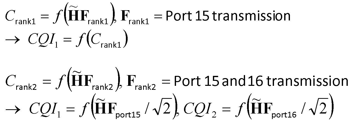
여기서 CQIi는 랭크 i을 가정하고 계산된 CQI를 의미하며, Franki 및 Fportj는 각각 랭크 i과 포트 j를 통한 전송을 가정하고 구해진 프리코딩 행렬을 의미하고, tilde_H는 추정된 채널 행렬을 의미하며, f는 미리 정해지는 함수를 의미한다. Here, CQI i means a calculated CQI assuming rank i, F ranki and F portj is a precoding matrix obtained assuming transmission through rank i and port j, respectively, tilde_H means the estimated channel matrix F means a predetermined function.
본 발명의 일 실시예로서, 비-코드북 기반 CSI 보고를 수행하기 위해, 기지국과 단말은 미리 약속된 코드북을 기반으로 RI 및 CQI를 계산할 수 있다. 상기 코드북은 단말에 의해 기지국으로 피드백되지 않지만 RI의 계산을 위해 기지국과 단말이 미리 알고 있는 것이다. 일 실시예로서 상기 코드북은 기지국이 상위 계층의 시그널링 메시지를 통해 단말에게 사전에 제공할 수 있다.As an embodiment of the present invention, in order to perform a non-codebook based CSI report, the base station and the terminal may calculate the RI and the CQI based on a previously promised codebook. The codebook is not fed back to the base station by the terminal, but is known in advance by the base station and the terminal for calculation of RI. In one embodiment, the codebook may be provided in advance by the base station to the terminal through a signaling message of a higher layer.
일 예로서 상기 코드북은 하기의 <표 3>과 같이 구성될 수 있다. 하기 예에서 코드북은 안테나 포트들 15 내지 22를 사용하는 1 내지 8 계층의 비-코드북 기반 CSI 보고를 위한 프리코더들을 포함한다.As an example, the codebook may be configured as shown in Table 3 below. In the following example the codebook includes precoders for 1-8 layers of non-codebook based CSI reporting using antenna ports 15-22.


일 실시예로서, 단말이 CQI의 계산 시 PDSCH 신호의 생성을 가정하기 위해 하기와 같이 동작할 수 있다.As an embodiment, the UE may operate as follows to assume the generation of the PDSCH signal when calculating the CQI.
υ 개의 레이어들을 위한 안테나 포트들 {7 ... 6+υ} 상의 PDSCH 신호들은 안테나 포트들 {15 ... 14+υ} 상에서 전송되는 해당 심볼들과 동일하며, 하기 <수학식 3>과 같이 주어진다.The PDSCH signals on the antenna ports {7 ... 6 + υ} for the υ layers are the same as the corresponding symbols transmitted on the antenna ports {15 ... 14 + υ}. Is given together.

여기서 x(i)는 레이어 매핑을 통해 얻어진 전송될 심볼들의 벡터이며, y(i)는 x(i)에 프리코더 W(i)를 적용하여 얻은 출력 벡터이고, P∈{1,2,4,8}는 단말에 대해 구성된 CSI-RS 포트들의 개수이다. 하나의 CSI-RS 포트가 구성된 경우 단말에 의해 가정된 프리코더를 의미하는 W(i)는 1이며, 그렇지 않은 경우 W(i)는 x(i)에 적용 가능한 보고될 RI(혹은 보고될 υ)에 대응하는 프리코딩 행렬이 된다.Where x (i) is a vector of symbols to be transmitted obtained through layer mapping, y (i) is an output vector obtained by applying the precoder W (i) to x (i), and P∈ {1,2,4 , 8} is the number of CSI-RS ports configured for the terminal. If one CSI-RS port is configured, W (i), which means the precoder assumed by the terminal, is 1, otherwise W (i) is the RI to be reported (or to be reported) applicable to x (i). ) Is a precoding matrix corresponding to
비-코드북 기반 CSI 보고를 수행하기 위해, 기지국과 단말은 미리 약속된 프리코딩 행렬을 기반으로 RI 및 CQI를 계산할 수 있다. 예를 들어 Wrank1을 1-레이어 전송을 위해 사용하는 프리코딩 행렬이라 하고, Wrank2를 2-레이어 전송을 위해 사용하는 프리코딩 행렬이라고 하면, 단말은 Wrank1과 Wrank2를 가정하여 RI를 결정하며, 기지국 또한 단말로부터 피드백 받은 RI를 데이터의 신호의 전송에 적용할 때 미리 알고 있는 Wrank1과 Wrank2를 가정하여 데이터 신호를 전송할 수 있다. 2개 이상의 레이어 전송을 위해서도 동일한 방법이 적용될 수 있다. In order to perform non-codebook based CSI reporting, the base station and the terminal may calculate the RI and the CQI based on a pre-arranged precoding matrix. For example, suppose that W rank1 is a precoding matrix that uses 1-layer transmission and W rank2 is a precoding matrix that uses 2-layer transmission. The UE determines RI by assuming W rank1 and W rank2 . In addition, the base station may transmit a data signal assuming W rank1 and W rank2 known in advance when applying the RI fed back from the terminal to the transmission of the signal of the data. The same method may be applied to transmitting two or more layers.
하기의 <표 4>는 기지국과 단말 사이에 미리 약속된 프리코딩 행렬들의 다른 예를 나타낸 것이다.Table 4 below shows another example of precoding matrices promised between the base station and the terminal.

일 실시예로서, 단말이 CQI의 계산 시 PDSCH 신호의 생성을 가정하기 위해 하기와 같이 동작할 수 있다.As an embodiment, the UE may operate as follows to assume the generation of the PDSCH signal when calculating the CQI.
υ 개의 레이어들을 위한 안테나 포트들 {7 ... 6+υ} 상의 PDSCH 신호들은 안테나 포트들 {15 ... 14+υ} 상에서 전송되는 해당 심볼들과 동일하며, 앞서 언급한 <수학식 3>과 같이 주어진다.The PDSCH signals on the antenna ports {7 ... 6 + υ} for υ layers are the same as the corresponding symbols transmitted on the antenna ports {15 ... 14 + υ}. Is given as
여기서 하나의 CSI-RS 포트가 구성된 경우 W(i)는 1이며, 2개의 CSI-RS 포트가 구성되고 보고되는 RI가 1인 경우 W(i)는 Wrank1,2Tx이고, 2개의 CSI-RS 포트가 구성되고 보고되는 RI가 2인 경우 W(i)는 Wrank2,2Tx이고, 4개의 CSI-RS 포트가 구성되고 보고되는 RI가 1이면 W(i)는 Wrank1,4Tx이고, 4개의 CSI-RS 포트가 구성되고 보고되는 RI가 2이면 W(i)는 Wrank2,4Tx이고, 4개의 CSI-RS 포트가 구성되고 보고되는 RI가 3이면 W(i)는 Wrank3,4Tx이고, 4개의 CSI-RS 포트가 구성되고 보고되는 RI가 4이면 W(i)는 Wrank4,4Tx이다. Here, if one CSI-RS port is configured, W (i) is 1, and if two CSI-RS ports are configured and reported RI is 1, W (i) is W rank1,2Tx and two CSI-RSs and if the RI is reported which port is configured 2 W (i) W is rank2,2Tx and, if the RI is four CSI-RS port is configured and report 1 W (i) W is rank1,4Tx, 4 If the CSI-RS port is configured and reported RI is 2, W (i) is W rank2,4Tx ; if four CSI-RS ports are configured and reported RI is 3, W (i) is W rank3,4Tx , If four CSI-RS ports are configured and the reported RI is 4, W (i) is W rank4,4Tx .
일 실시예로서 비-코드북 기반 CSI 보고를 수행하기 위해 기지국과 단말 사이에 미리 약속되는 코드북은, LTE 표준에서 기 사용되던 코드북이 될 수 있다. 일 예로, LTE Rel-8에 정의된 2Tx 코드북 혹은 LTE Rel-8에 정의된 4Tx 코드북이 사용될 수 있다. 다른 실시예로서, LTE 표준에서 기 사용되던 코드북에서 특정 코드워드를 확장하여 비-코드북 기반 CSI 보고를 위해 적용할 수 있다. 그러면, 단말은 CQI 계산 시 PDSCH 신호의 생성을 가정하기 위해 아래와 같이 동작할 수 있다.According to an embodiment, a codebook previously promised between a base station and a terminal to perform non-codebook based CSI reporting may be a codebook previously used in the LTE standard. For example, a 2Tx codebook defined in LTE Rel-8 or a 4Tx codebook defined in LTE Rel-8 may be used. In another embodiment, a specific codeword may be extended from a codebook previously used in the LTE standard and applied to non-codebook based CSI reporting. Then, the UE may operate as follows to assume generation of the PDSCH signal when calculating the CQI.
υ 개의 레이어들을 위한 안테나 포트들 {7 ... 6+υ} 상의 PDSCH 신호들은 안테나 포트들 {15 ... 14+P} 상에서 전송되는 해당 심볼들과 동일하며, 앞서 언급한 <수학식 3>과 같이 주어진다.The PDSCH signals on the antenna ports {7 ... 6 + υ} for υ layers are the same as the corresponding symbols transmitted on the antenna ports {15 ... 14 + P}. Is given as
여기서 하나의 CSI-RS 포트가 구성된 경우 W(i)는 1이다.Here, if one CSI-RS port is configured, W (i) is one.
2개의 CSI-RS 포트가 구성된 경우 W(i)는 LTE 표준에 주어진 모든 레이어들에 대한 코드북 인덱스 A에 대응하며, 4개의 CSI-RS 포트가 구성된 경우 W(i)는 LTE 표준에 주어진 모든 레이어들에 대한 코드북 인덱스 B에 대응하며, 8개의 CSI-RS 포트가 구성된 경우 W(i)는 각 해당 레이어 개수에 대해 주어진 코드북 인덱스 C에 대응한다.W (i) corresponds to codebook index A for all layers given in the LTE standard when two CSI-RS ports are configured, and W (i) corresponds to all layers given in the LTE standard when four CSI-RS ports are configured. The codebook index B corresponds to the codebook index B for each of the two CSI-RS ports and W (i) corresponds to the given codebook index C for each corresponding layer number.
여기서 A, B, C의 값들은 0이 될 수도 있고, 또는 그 외의 임의의 값이 될 수도 있다. 또한, C는 2개의 값을 가질 수 있다. 예를 들어 C는 i1=0, i2=0의 값을 가질 수도 있고, 또는 그 외의 임의의 2개의 값이 사용될 수도 있다. Here, the values of A, B, and C may be 0 or any other value. C may also have two values. For example, C may have values of i1 = 0, i2 = 0, or any other two values may be used.
일 실시예에서 레이어 별로 A, B, C의 값들이 다르게 지정될 수 있다. 이 경우, 단말이 CQI 계산 시 PDSCH 신호의 생성을 가정하기 위해 하기와 같이 동작할 수 있다.In an embodiment, values of A, B, and C may be differently designated for each layer. In this case, the UE may operate as follows to assume generation of the PDSCH signal when calculating the CQI.
υ 개의 레이어들을 위한 안테나 포트들 {7 ... 6+υ} 상의 PDSCH 신호들은 안테나 포트들 {15 ... 14+υ} 상에서 전송되는 해당 심볼들과 동일하며, 앞서 언급한 <수학식 3>과 같이 주어진다.The PDSCH signals on the antenna ports {7 ... 6 + υ} for υ layers are the same as the corresponding symbols transmitted on the antenna ports {15 ... 14 + υ}. Is given as
여기서 하나의 CSI-RS 포트가 구성된 경우 W(i)는 1이며, 2개의 CSI-RS 포트들이 구성되고 보고되는 RI가 1인 경우 W(i)는 υ=1을 가지는 코드북 인덱스 A1이며, 2개의 CSI-RS 포트들이 구성되고 보고되는 RI가 2인 경우 W(i)는 υ=2를 가지는 코드북 인덱스 A2이며, 4개의 CSI-RS 포트들이 구성되고 보고되는 RI가 1인 경우 W(i)는 υ=1를 가지는 코드북 인덱스 B1이며, 4개의 CSI-RS 포트들이 구성되고 보고되는 RI가 2인 경우 W(i)는 υ=2를 가지는 코드북 인덱스 B2이며, 4개의 CSI-RS 포트들이 구성되고 보고되는 RI가 3인 경우 W(i)는 υ=3를 가지는 코드북 인덱스 B3이며, 4개의 CSI-RS 포트들이 구성되고 보고되는 RI가 4인 경우 W(i)는 υ=4를 가지는 코드북 인덱스 B4이다.Here, when one CSI-RS port is configured, W (i) is 1, and when two CSI-RS ports are configured and reported RI is 1, W (i) is a codebook index A1 having υ = 1, 2 W (i) is 2 if the CSI-RS ports are configured and reported, and W (i) is a codebook index A2 with υ = 2. Is a codebook index B1 with υ = 1, four CSI-RS ports are configured and if the reported RI is 2, W (i) is a codebook index B2 with υ = 2 and four CSI-RS ports are configured. And if the reported RI is 3, W (i) is a codebook index B3 with υ = 3, and four CSI-RS ports are configured and if the reported RI is 4, W (i) is a codebook with υ = 4. Index B4.
상기 실시예는 8 포트들이 사용되는 경우도 동일하게 확장이 가능하다. 또한 A1, A2, B1, B2, B3, B4의 값들은 서로 다를 수 있다.The above embodiment is equally expandable when 8 ports are used. Also, the values of A1, A2, B1, B2, B3, and B4 may be different from each other.
이하에서는 비-코드북 기반 CSI 보고를 위해 사용될 수 있는 미리 정의된 프리코딩 행렬들을 상위 계층 시그널링을 통해 설정하는 실시예를 설명한다.Hereinafter, an embodiment of setting predefined precoding matrices that can be used for non-codebook based CSI reporting through higher layer signaling will be described.
비-코드북 기반 CSI 보고를 수행함에 있어서, 기지국과 단말은 미리 약속된 프리코딩 행렬들을 기반으로 RI 및 CQI를 선택하며, 여기서 상기 미리 약속된 프리코딩 행렬들은 RRC 시그널링과 같은 상위 계층 시그널링을 통해 설정될 수 있다. In performing non-codebook based CSI reporting, a base station and a terminal select RI and CQI based on pre-promised precoding matrices, wherein the pre-promised precoding matrices are configured through higher layer signaling such as RRC signaling. Can be.
도 13은 본 발명의 일 실시예에 따른 무선 통신 시스템에서 비-코드북 기반 CSI 보고를 수행하는 시나리오를 나타낸 도면이다. 도시된 시나리오는 기지국(eNB)(1302)과 사용자 단말(UE)(1304) 간의 통신을 포함한다.FIG. 13 illustrates a scenario of performing non-codebook based CSI reporting in a wireless communication system according to an embodiment of the present invention. The illustrated scenario includes communication between a base station (eNB) 1302 and a user terminal (UE) 1304.
도 13을 참조하면, 과정 1310에서 기지국(102)은 단말(1104)의 무선 통신에 필요한 각종 구성 정보를 포함하는 RRC 구성 메시지를 단말(1104)에게 전송한다. 일 예로서 상기 RRC 구성 메시지는 단말(1104)이 사용할 수 있는 프리코딩 행렬들을 포함하는 코드북을 지시하는 정보를 포함할 수 있다.Referring to FIG. 13, in step 1310, the base station 102 transmits an RRC configuration message including various configuration information necessary for wireless communication of the terminal 1104 to the terminal 1104. As an example, the RRC configuration message may include information indicating a codebook including precoding matrices available to the UE 1104.
과정 1312에서 단말(1304)은 기지국(1302)에 SRS를 전송하고, 과정 1314에서 기지국(1300)은 상기 수신된 SRS에 대한 채널 추정을 기반으로 단말 별 프리코딩을 수행하기 위한 1차 빔포밍 정보를 결정한다. 도시하지 않을 것이나, SRS 대신 긴 주기로 전송되는 CSI-RS가 이용되는 경우, 과정 1312는 기지국(1302)은 긴 주기의 CSI-RS를 단말(1304)에게 전송하고, 채널 상태 정보를 단말(1304)로부터 수신하는 동작으로 대체될 수 있다.In step 1312, the terminal 1304 transmits an SRS to the base station 1302, and in step 1314, the base station 1300 performs primary beamforming information for performing terminal-specific precoding based on channel estimation for the received SRS. Determine. Although not shown, when the CSI-RS transmitted in a long period instead of the SRS is used, in step 1312, the base station 1302 transmits the long period CSI-RS to the terminal 1304 and transmits channel state information to the terminal 1304. May be replaced by the operation received from.
과정 1316에서 기지국(1302)은 상기 1차 빔포밍 정보에 따라 BF-CSI-RS를 단말(1304)에게 전송한다. 상기 1차 빔포밍 정보는 단말(1304)에 대해 적합하게 선택된 프리코딩 행렬을 포함할 수 있다. 과정 1318에서 단말(1304)은 상기 수신된 BF-CSI-RS에 대한 측정 결과를 기반으로 CSI를 계산한다. 단말이 PMI 보고를 수행하지 않도록 구성된 경우, 단말은 상기 RRC 구성 메시지에 의해 지시된 코드북을 기반으로 피드백을 위한 RI 및 CQI를 결정할 수 있다.In step 1316, the base station 1302 transmits the BF-CSI-RS to the terminal 1304 according to the primary beamforming information. The primary beamforming information may include a precoding matrix appropriately selected for the terminal 1304. In step 1318, the terminal 1304 calculates the CSI based on the measurement result for the received BF-CSI-RS. When the terminal is configured not to perform the PMI report, the terminal may determine the RI and CQI for feedback based on the codebook indicated by the RRC configuration message.
과정 1320에서 단말(1304)은 상기 RI 및 CQI를 포함하는 CSI를 기지국(1302)에게 보고하며, 과정 1322에서 기지국(1302)은 상기 RRC 구성 메시지에 의해 지시되고 단말이 RI 및 CQI를 결정하기 위해 사용한 코드북과, 상기 보고된 CSI를 기반으로 다운링크 전송에 적용될 RI 및 CQI를 보상하고 프리코딩 조정을 수행하여 2차 빔포밍 정보를 결정한다. 과정 1324에서 기지국(1302)은 상기 2차 빔포밍 정보에 따라 전송 포트 별 빔포밍이 적용된 데이터 신호를 PDSCH를 통해 단말(104)에게 전송한다. In step 1320, the terminal 1304 reports the CSI including the RI and the CQI to the base station 1302. In step 1322, the base station 1302 is indicated by the RRC configuration message and the terminal determines the RI and the CQI. Based on the used codebook and the reported CSI, the second beamforming information is determined by compensating RI and CQI to be applied to downlink transmission and performing precoding adjustment. In step 1324, the base station 1302 transmits a data signal to which beamforming for each transmission port is applied to the terminal 104 through the PDSCH according to the secondary beamforming information.
일 실시예로서 상기 RRC 구성 메시지는 하기와 같은 구성 정보를 포함할 수 있다.As an embodiment, the RRC configuration message may include configuration information as follows.
CQI-ABC-r1x ::= SEQUENCE {CQI-ABC-r1x :: = SEQUENCE {
codebook-no-pmi-Report-r1x ENUMERATED {setup} or BIT STRING OPTIONAL codebook-no-pmi-Report-r1x ENUMERATED {setup} or BIT STRING OPTIONAL
}}
상기 CQI-ABC 정보에 포함되는 codebook-no-pmi-Report 파라미터는 비-코드북 기반 CSI 보고가 사용되고 CSI-RS 안테나 포트 개수가 2 이상인 경우, 단말에서 RI 및 CQI의 계산을 위해 사용되는 프리코딩 행렬 인덱스(precoding matrix index: PMI)를 지정한다.The codebook-no-pmi-Report parameter included in the CQI-ABC information is a precoding matrix used for calculating RI and CQI in the UE when non-codebook based CSI reporting is used and the number of CSI-RS antenna ports is 2 or more. Specifies an index (precoding matrix index (PMI)).
일 실시예로서, 단말은 CQI의 계산 시 PDSCH 신호의 생성을 가정하기 위해 하기와 같이 동작할 수 있다.As an embodiment, the UE may operate as follows to assume generation of a PDSCH signal when calculating a CQI.
υ 개의 레이어들을 위한 안테나 포트들 {7 ... 6+υ} 상의 PDSCH 신호들은 안테나 포트들 {15 ... 14+υ} 상에서 전송되는 해당 심볼들과 동일하며, 앞서 언급한 <수학식 3>과 같이 주어진다. 여기서 하나의 CSI-RS 포트가 구성된 경우 W(i)는 1이며, 그렇지 않은 경우 W(i)는 상위 계층 시그널링을 통해 기지국에 의해 선택된 프리코딩 행렬을 의미한다.The PDSCH signals on the antenna ports {7 ... 6 + υ} for υ layers are the same as the corresponding symbols transmitted on the antenna ports {15 ... 14 + υ}. Is given as Here, if one CSI-RS port is configured, W (i) is 1; otherwise, W (i) means a precoding matrix selected by the base station through higher layer signaling.
다른 실시예로서 구성된 CSI-RS 포트의 개수가 2개 이상인 경우, W(i)는 x(i)에 적용 가능한 보고될 RI(혹은 보고될 υ)에 대응하는 프리코딩 행렬로서, 상위 계층 시그널링에 의해 주어질 수 있다.In another embodiment, when the number of CSI-RS ports configured is two or more, W (i) is a precoding matrix corresponding to RI to be reported (or υ to be reported) applicable to x (i), and is applied to higher layer signaling. Can be given by
하기에서는 PMI를 함께 보고하는 채널 피드백 기법을 설명한다.The following describes a channel feedback technique for reporting PMI together.
단말은 기지국과 단말 사이에 미리 약속된 코드북 중 최적의 코드워드에 대응하는 프리코딩 행렬을 선택하여, 기지국에게 CQI 및 RI와 함께 상기 선택된 프리코딩 행렬에 대한 PMI를 전달할 수 있다. 상기 코드북은 일 예로서 하기 <표 5>와 같이 구성될 수 있다. The terminal may select a precoding matrix corresponding to an optimal codeword among codebooks previously promised between the base station and the terminal, and transmit the PMI for the selected precoding matrix along with the CQI and RI to the base station. The codebook may be configured as shown in Table 5 as an example.

상기 코드북을 지시하기 위해, 하기와 같은 상위 계층 시그널링이 사용될 수 있다.In order to indicate the codebook, the following higher layer signaling may be used.
AntennaInfo-ABC-r1x ::= SEQUENCE {AntennaInfo-ABC-r1x :: = SEQUENCE {
alternativeCodebookEnabledForABC-r1x BOOLEAN or ENUMERATED or BIT STRING alternativeCodebookEnabledForABC-r1x BOOLEAN or ENUMERATED or BIT STRING
}}
상기 AntennaInfo-ABC 정보에 포함되는 alternativeCodebookEnabledForABC 파라미터는 비-코드북 기반 CSI 보고가 사용되는 경우, 미리 약속된 코드북, 일 예로서 <표 5>와 같은 코드북이 사용됨을 지시한다.The alternativeCodebookEnabledForABC parameter included in the AntennaInfo-ABC information indicates that when a non-codebook based CSI report is used, a previously promised codebook, for example, a codebook as shown in Table 5 is used.
일 실시예로서, 기지국은 비-코드북 기반 CSI 보고의 사용을 단말에게 지시하기 위해 하기와 같은 상위 계층 시그널링을 단말에게 전송할 수 있다. In one embodiment, the base station may transmit the following higher layer signaling to the terminal to instruct the terminal of the use of non-codebook based CSI reporting.
CQI-ReportXYZ-r1y ::= SEQUENCE {CQI-ReportXYZ-r1y :: = SEQUENCE {
RI-CQI-Report-r1y ENUMERATED {setup}RI-CQI-Report-r1y ENUMERATED {setup}
}}
즉 상기 CQI-ReportXYZ에 포함되는 RI-CQI-Report 파라미터는 RI와 CQI를 피드백하는 비-코드북 기반 CSI 보고의 사용을 단말에게 지시한다. 다시 말해서 기지국으로부터 단말로 전송되는 RRC 시그널링에 상기 파라미터가 포함되어 있는 경우, 상기 단말은 PMI의 보고를 수행하지 않도록 구성된다.That is, the RI-CQI-Report parameter included in the CQI-ReportXYZ indicates to the UE the use of non-codebook based CSI reporting for feeding back the RI and the CQI. In other words, when the parameter is included in the RRC signaling transmitted from the base station to the terminal, the terminal is configured not to perform the report of the PMI.
이 경우, 단말은 CQI의 계산을 위해 단말에 대해 구성된 전송 모드에 기반하여 PDSCH 전송 방식을 가정할 수 있다.In this case, the terminal may assume a PDSCH transmission scheme based on a transmission mode configured for the terminal for calculating the CQI.
하기의 <표 6>은 CSI 기준 자원을 위해 가정된 PDSCH 전송 방식의 일 예를 설명하는 것이다.Table 6 below describes an example of a PDSCH transmission scheme assumed for CSI reference resources.
| Transmission modeTransmission mode | Transmission scheme of PDSCHTransmission scheme of PDSCH |
| 99 | If the UE is configured without PMI/RI reporting: if the number of PBCH antenna ports is one, single-antenna port, port 0; otherwise transmit diversityIf the UE is configured with RI/CQI reporting: if the number of PBCH antenna ports is one, single-antenna port, port 0, otherwise up to 8 layer transmission, port 7-14;If the UE is configured with PMI/RI reporting: if the number of CSI-RS ports is one, single-antenna port, port 7; otherwise up to 8 layer transmission, ports 7-14If the UE is configured without PMI / RI reporting: if the number of PBCH antenna ports is one, single-antenna port, port 0; otherwise transmit diversityIf the UE is configured with RI / CQI reporting: if the number of PBCH antenna ports is one, single-antenna port, port 0, otherwise up to 8 layer transmission, port 7-14; If the UE is configured with PMI / RI reporting: if the number of CSI-RS ports is one, single-antenna port, port 7; otherwise up to 8 layer transmission, ports 7-14 |
| 1010 | If a CSI process of the UE is configured without PMI/RI reporting: if the number of CSI-RS ports is one, single-antenna port, port7; otherwise transmit diversityIf a CSI process of the UE is configured with RI/CQI reporting: if the number of CSI-RS ports is one, single-antenna port, port 0, otherwise* up to 8 layer transmission, port 7-14; If a CSI process of the UE is configured with PMI/RI reporting: if the number of CSI-RS ports is one, single-antenna port, port 7; otherwise up to 8 layer transmission, ports 7-14If a CSI process of the UE is configured without PMI / RI reporting: if the number of CSI-RS ports is one, single-antenna port, port 7; otherwise transmit diversity If a CSI process of the UE is configured with RI / CQI reporting: if the number of CSI-RS ports is one, single-antenna port, port 0, otherwise * up to 8 layer transmission, port 7-14; If a CSI process of the UE is configured with PMI / RI reporting: if the number of CSI-RS ports is one, single-antenna port, port 7; otherwise up to 8 layer transmission, ports 7-14 |
하기의 <표 7>은 CSI 기준 자원을 위해 가정된 PDSCH 전송 방식의 다른 예를 설명하는 것이다.Table 7 below describes another example of a PDSCH transmission scheme assumed for CSI reference resources.
| Transmission modeTransmission mode | Transmission scheme of PDSCHTransmission scheme of PDSCH |
| 99 | If the UE is configured without PMI/RI reporting: if the number of PBCH antenna ports is one, single-antenna port, port 0; otherwise transmit diversityIf the UE is configured with RI/CQI reporting or PMI/RI reporting: if the number of PBCH antenna ports is one, single-antenna port, port 0, otherwise up to 8 layer transmission, port 7-14; If the UE is configured without PMI / RI reporting: if the number of PBCH antenna ports is one, single-antenna port, port 0; otherwise transmit diversity If the UE is configured with RI / CQI reporting or PMI / RI reporting: if the number of PBCH antenna ports is one, single-antenna port, port 0, otherwise up to 8 layer transmission, port 7-14; |
| 1010 | If a CSI process of the UE is configured without PMI/RI reporting: if the number of CSI-RS ports is one, single-antenna port, port7; otherwise transmit diversityIf a CSI process of the UE is configured with RI/CQI reporting or PMI/RI reporting: if the number of CSI-RS ports is one, single-antenna port, port 0, otherwise* up to 8 layer transmission, port 7-14; If a CSI process of the UE is configured without PMI / RI reporting: if the number of CSI-RS ports is one, single-antenna port, port 7; otherwise transmit diversity if a CSI process of the UE is configured with RI / CQI reporting or PMI / RI reporting: if the number of CSI-RS ports is one, single-antenna port, port 0, otherwise * up to 8 layer transmission, port 7-14; |
일 실시예로서, 단말은 CSI 보고를 위한 채널 정보를 계산하기 위해 아래와 같이 동작할 수 있다.As an embodiment, the terminal may operate as follows to calculate channel information for CSI reporting.
비주기적 CSI 보고를 위한 모드 3-0 및 2-0에서, 전송 모드 3에 대해 보고될 CQI 값들은 보고될 RI에 기반하여 계산된다. 전송 모드 9 및 10에서, 상위 계층 시그널링을 통해 비-코드북 기반 CSI 보고를 지시하는 파라미터, 일 예로 RI-CQI-Report 정보가 단말에게 구성된 경우, 보고될 CQI 값들은 보고될 RI에 기반하여 계산된다. 그렇지 않은 경우, 보고될 CQI 값들은 랭크 1에 기반하여 계산된다.In modes 3-0 and 2-0 for aperiodic CSI reporting, the CQI values to be reported for transmission mode 3 are calculated based on the RI to be reported. In transmission modes 9 and 10, when a parameter indicating non-codebook based CSI reporting through higher layer signaling, for example, RI-CQI-Report information is configured to the UE, CQI values to be reported are calculated based on the RI to be reported. . Otherwise, the CQI values to be reported are calculated based on rank 1.
주기적 CSI 보고를 위한 모드 1-0 및 2-0에서, RI를 보고할 서브프레임에서 단말은 S개의 서브밴드들의 세트에 대한 전송을 가정하고 RI를 결정하며, 하나의 RI를 포함하는 보고를 기지국으로 전송한다. (광대역) CQI를 보고할 서브프레임에서 전송 모드 3인 경우 CQI는 마지막 보고된 주기적 RI에 대해 계산된다. (광대역) CQI를 보고할 서브프레임에서 전송 모드 9 및 10에 대해, 상위 계층 시그널링을 통해 비-코드북 기반 CSI 보고를 지시하는 파라미터, 일 예로 RI-CQI-Report 정보가 단말에게 구성된 경우 CQI는 마지막 보고된 주기적 RI에 대해 계산되며, 다른 전송 모드들에 대해 CQI는 랭크 1을 가정하고 계산된다. 선택된 서브밴드에 대한 CQI를 보고할 서브프레임에서 전송 모드 3인 경우 선호 서브밴드의 선택 및 CQI 값들은 마지막 보고된 주기적 RI를 기반으로 계산된다. 선택된 서브밴드에 대한 CQI를 보고할 서브프레임에서 전송 모드 9 및 10에 대해, 상위 계층 시그널링을 통해 비-코드북 기반 CSI 보고를 지시하는 파라미터, 일 예로 RI-CQI-Report 정보가 단말에게 구성된 경우 CQI는 마지막 보고된 주기적 RI에 대해 계산되며, 다른 전송 모드들에 대해 CQI는 랭크 1을 가정하고 계산된다.In modes 1-0 and 2-0 for periodic CSI reporting, in a subframe to report an RI, the UE assumes transmission for a set of S subbands and determines an RI, and reports a report including one RI to a base station. To send. In transmission mode 3 in the subframe to report (broadband) CQI, the CQI is calculated for the last reported periodic RI. (Broadband) for transmission modes 9 and 10 in a subframe to report CQI, a parameter indicating non-codebook based CSI reporting through higher layer signaling, for example, when RI-CQI-Report information is configured in the UE, CQI is the last It is calculated for the reported periodic RI, and for other transmission modes, the CQI is calculated assuming rank 1. In transmission mode 3 in the subframe in which the CQI for the selected subband is to be reported, the selection of the preferred subband and the CQI values are calculated based on the last reported periodic RI. For transmission modes 9 and 10 in a subframe in which the CQI for the selected subband is to be reported, a parameter indicating non-codebook based CSI reporting through higher layer signaling, for example, when the RI-CQI-Report information is configured in the UE, the CQI Is calculated for the last reported periodic RI, and for other transmission modes, CQI is calculated assuming rank 1.
다른 실시예로서 기지국은 CSI 보고 클래스와 전송 다이버시티 CQI의 측정을 지시하는 상위 계층 시그널링을 조합하여, 비-코드북 CSI 보고의 사용을 단말에게 지시할 수 있다. 이를 위해 기지국은 하기와 같은 상위 계층 시그널링을 단말에게 전송할 수 있다.In another embodiment, the base station may combine the CSI report class and the higher layer signaling indicating the measurement of the transmit diversity CQI to instruct the UE to use the non-codebook CSI report. To this end, the base station may transmit the following higher layer signaling to the terminal.
CSI-Process-r1y ::= SEQUENCE {CSI-Process-r1y :: = SEQUENCE {
csi-reporting-class ENUMERATED {class X, class Y, class Z},csi-reporting-class ENUMERATED {class X, class Y, class Z},
}}
CQI-ReportABC-r1x ::= SEQUENCE {CQI-ReportABC-r1x :: = SEQUENCE {
pmi-RI-Report-r1x ENUMERATED {setup} OPTIONAL -- Need ORpmi-RI-Report-r1x ENUMERATED {setup} OPTIONAL-Need OR
}}
여기서 CSI-Process 정보에 포함되는 csi-reporting-class 파라미터는 단말에게 CSI 보고 클래스를 지정한다. 여기서 클래스 X, Y, Z 및 클래스 B가 사용될 수 있다.Here, the csi-reporting-class parameter included in the CSI-Process information designates the CSI reporting class to the terminal. Here class X, Y, Z and class B can be used.
또한 CQI-ReportABC 정보에 포함되는 pmi-RI-Report 파라미터는 PMI/RI 보고를 단말에게 구성할 것을 지시하기 위해 사용된다. 상기 파라미터가 상기 CQI 보고 구성 정보 내에 존재하는 경우, 단말은 PMI/RI 보고를 수행할 것으로 결정한다. 상기 파라미터가 존재하지 않는 경우 단말은 PMI/RI 보고가 설정되지 않은 것으로 판단한다. 기지국은 전송 모드 8, 9 or 10이 구성된 경우에 상기 파라미터를 설정할 수 있다. 단말은 현재 반송파 주파수 상의 서빙 셀에 대해 전송 모드 10이 구성된 경우, 상기 파라미터를 무시할 수 있다.In addition, the pmi-RI-Report parameter included in the CQI-ReportABC information is used to instruct the terminal to configure the PMI / RI report. If the parameter is present in the CQI report configuration information, the terminal determines to perform the PMI / RI report. If the parameter does not exist, the terminal determines that the PMI / RI report is not set. The base station may set the parameter when the transmission mode 8, 9 or 10 is configured. When the transmission mode 10 is configured for the serving cell on the current carrier frequency, the terminal may ignore the parameter.
기지국에 의해 CSI 보고 클래스와 pmi-RI-report 파라미터가 설정되지 않은 경우, 단말은 비-코드북 기반 CSI 보고를 수행할 것으로 결정한다. 단말이 CQI 계산 시 PDSCH 신호의 생성을 가정하기 위해 하기의 <표 8>과 같이 동작할 수 있다.If the CSI reporting class and the pmi-RI-report parameter are not set by the base station, the terminal determines to perform non-codebook based CSI reporting. The UE may operate as shown in Table 8 below to assume generation of a PDSCH signal when calculating a CQI.
| Transmission modeTransmission mode | Transmission scheme of PDSCHTransmission scheme of PDSCH |
| 99 | If the UE is configured without PMI/RI reporting: if the number of PBCH antenna ports is one, single-antenna port, port 0; if the UE is configured with Class X CSI reporting, up to 8 layer transmission, port 7-14; otherwise transmit diversityIf the UE is configured without PMI / RI reporting: if the number of PBCH antenna ports is one, single-antenna port, port 0; if the UE is configured with Class X CSI reporting, up to 8 layer transmission, port 7-14; otherwise transmit diversity |
| 1010 | If a CSI process of the UE is configured without PMI/RI reporting: if the number of CSI-RS ports is one, single-antenna port, port7; if a CSI process with Class X CSI reporting of the UE is configured, up to 8 layer transmission, port 7-14; otherwise transmit diversityIf a CSI process of the UE is configured without PMI / RI reporting: if the number of CSI-RS ports is one, single-antenna port, port 7; if a CSI process with Class X CSI reporting of the UE is configured, up to 8 layer transmission, port 7-14; otherwise transmit diversity |
CSI 기준 자원에서 단말은 CQI 인덱스 및 필요한 경우 PMI와 RI를 결정하기 위해 하기와 같이 가정한다. In the CSI reference resource, the UE assumes the following to determine the CQI index and, if necessary, PMI and RI.
전송 모드 9에 대한 CSI 보고는 하기와 같이 동작한다.The CSI reporting for transmission mode 9 operates as follows.
단말이 PMI 보고를 수행하지 않도록 구성되고(혹은 PMI/RI 보고를 수행하지 않도록 구성되고) CSI 보고를 위한 클래스 X (혹은 클래스 B)로 구성된 경우, 단말 특정 기준 신호 오버헤드는 하나보다 많은 CSI-RS 포트에 대해서는 가장 최근 보고된 랭크와 일치하며, 하나의 CSI-RS 포트에 대해서는 랭크 1 전송시와 일치한다. υ 개의 레이어들을 위한 안테나 포트들 {7 ... 6+υ} 상의 PDSCH 신호들은 안테나 포트들 {15 ... 14+υ} 상에서 전송되는 해당 심볼들과 동일하며, 앞서 설명한 <수학식 3>과 같이 주어진다.If the terminal is configured not to perform PMI reporting (or is configured not to perform PMI / RI reporting) and is configured with class X (or class B) for CSI reporting, the terminal specific reference signal overhead is more than one CSI- It matches the most recently reported rank for the RS port and matches for rank 1 transmission for one CSI-RS port. The PDSCH signals on the antenna ports {7 ... 6 + υ} for υ layers are the same as the corresponding symbols transmitted on the antenna ports {15 ... 14 + υ}, as described above. Is given by
여기서 하나의 CSI-RS 포트가 구성된 경우 W(i)는 1이다. 그렇지 않은 경우 W(i)는 2개의 CSI-RS 포트가 구성된 경우 모든 레이어에 대해 코드북 인덱스 A이며, 4개의 CSI-RS 포트가 구성된 경우 모든 레이어에 대해 코드북 인덱스 B이고, 8개의 CSI-RS 포트가 구성된 경우 해당하는 개수의 레이어들에 대해 코드북 인덱스 C로 주어진다. 안테나 포트들 {15 ... 14+P} 상에서 전송되는 해당 PDSCH 신호들은 주어진 값과 동일한 EPRE(energy per resource element) 대비 CSI-RS EPRE의 비율을 가진다.Here, if one CSI-RS port is configured, W (i) is one. Otherwise, W (i) is codebook index A for all layers if two CSI-RS ports are configured, codebook index B for all layers if four CSI-RS ports are configured, and eight CSI-RS ports. If is configured, the codebook index C for the corresponding number of layers is given. The corresponding PDSCH signals transmitted on the antenna ports {15 ... 14 + P} have a ratio of CSI-RS EPRE to energy per resource element (EPRE) equal to a given value.
CSI 프로세스가 PMI/RI 보고를 수행하지 않도록 구성된 경우 전송 모드 10에 대한 CSI 보고는 하기와 같이 동작한다.If the CSI process is configured not to perform PMI / RI reporting, the CSI reporting for transmission mode 10 operates as follows.
관련 CSI-RS 자원에 대해 하나보다 많은 CSI-RS 포트가 구성되고, 단말이 CSI 보고를 위한 클래스 X(혹은 클래스 B)로 구성된 경우, CRS 자원 요소(resource elements: REs)는 비-MBSFN(multicast-broadcast single-frequency network) 서브프레임들 내에 존재하며, CRS 오버헤드는 서빙 셀의 CRS 안테나 포트 개수에 대응하는 CRS 오버헤드와 동일한 것으로 간주된다. UE 특정 기준 신호 오버헤드는 하나보다 많은 CSI-RS 포트에 대해서는 가장 최근 보고된 랭크와 일치하며, 하나의 CSI-RS 포트에 대해서는 랭크 1 전송시와 일치한다. 하나의 CSI-RS 포트에 대해서는 랭크 1 전송시와 일치한다. υ 개의 레이어들을 위한 안테나 포트들 {7 ... 6+υ} 상의 PDSCH 신호들은 안테나 포트들 {15 ... 14+υ} 상에서 전송되는 해당 심볼들과 동일하며, 앞서 설명한 <수학식 3>과 같이 주어진다.If more than one CSI-RS port is configured for the relevant CSI-RS resources, and the UE is configured with Class X (or Class B) for CSI reporting, CRS resource elements (REs) are non-multicast -broadcast single-frequency network) subframes, where the CRS overhead is considered equal to the CRS overhead corresponding to the number of CRS antenna ports of the serving cell. The UE specific reference signal overhead is consistent with the most recently reported rank for more than one CSI-RS port and with rank 1 transmission for one CSI-RS port. For one CSI-RS port, this coincides with rank 1 transmission. The PDSCH signals on the antenna ports {7 ... 6 + υ} for υ layers are the same as the corresponding symbols transmitted on the antenna ports {15 ... 14 + υ}, as described above. Is given by
여기서 P=1이면 W(i)는 1이다. 그렇지 않은 경우 W(i)는 2개의 CSI-RS 포트가 구성된 경우 모든 레이어에 대해 코드북 인덱스 A이며, 4개의 CSI-RS 포트가 구성된 경우 모든 레이어에 대해 코드북 인덱스 B이고, 8개의 CSI-RS 포트가 구성된 경우 해당하는 개수의 레이어들에 대해 코드북 인덱스 C로 주어진다. 안테나 포트들 {15 ... 14+P} 상에서 전송되는 해당 PDSCH 신호들은 주어진 값과 동일한 EPRE(energy per resource element) 대비 CSI-RS EPRE의 비율을 가진다.If P = 1, W (i) is 1. Otherwise, W (i) is codebook index A for all layers if two CSI-RS ports are configured, codebook index B for all layers if four CSI-RS ports are configured, and eight CSI-RS ports. If is configured, the codebook index C for the corresponding number of layers is given. The corresponding PDSCH signals transmitted on the antenna ports {15 ... 14 + P} have a ratio of CSI-RS EPRE to energy per resource element (EPRE) equal to a given value.
CSI-RS 및 넌-제로 CSI-RS에 대해서는 RE들이 할당되지 않는 것으로 가정한다.It is assumed that REs are not assigned for CSI-RS and non-zero CSI-RS.
앞서 설명한 실시예들에서 사용한 코드북 인덱스들은 상위 계층 시그널링에 의해 주어지는 프리코더 및/혹은 미리 정의되는 프리코더들을 지시할 수 있다.Codebook indices used in the above-described embodiments may indicate precoders and / or predefined precoders given by higher layer signaling.
다른 실시예로서, 상기 미리 정의되는 프리코더에 코드북 서브셋 제한(codebook subset restriction)을 적용하여, 단말이 계산할 수 있는 코드워드 수를 제한할 수 있다. In another embodiment, a codebook subset restriction may be applied to the predefined precoder to limit the number of codewords that the terminal can calculate.
CSI 기준 자원에서 단말은 CQI 인덱스 및 필요한 경우 PMI와 RI를 결정하기 위해 하기와 같이 가정한다.In the CSI reference resource, the UE assumes the following to determine the CQI index and, if necessary, PMI and RI.
전송 모드 9에 대한 CSI 보고는 하기와 같이 동작한다.The CSI reporting for transmission mode 9 operates as follows.
단말이 PMI/RI 보고(혹은 PMI 보고)를 수행하지 않도록 구성되고 CSI 보고를 위한 클래스 X (혹은 클래스 B)로 구성된 경우, 단말 특정 기준 신호 오버헤드는 하나보다 많은 CSI-RS 포트에 대해서는 가장 최근 보고된 랭크와 일치하며, 하나의 CSI-RS 포트에 대해서는 랭크 1 전송시와 일치한다. υ 개의 레이어들을 위한 안테나 포트들 {7 ... 6+υ} 상의 PDSCH 신호들은 안테나 포트들 {15 ... 14+υ} 상에서 전송되는 해당 심볼들과 동일하며, 앞서 설명한 <수학식 3>과 같이 주어진다.If the UE is configured not to perform PMI / RI reporting (or PMI reporting) and is configured with Class X (or Class B) for CSI reporting, the UE-specific reference signal overhead is most recent for more than one CSI-RS port. It is consistent with the reported rank and with the rank 1 transmission for one CSI-RS port. The PDSCH signals on the antenna ports {7 ... 6 + υ} for υ layers are the same as the corresponding symbols transmitted on the antenna ports {15 ... 14 + υ}, as described above. Is given by
여기서 하나의 CSI-RS 포트가 구성된 경우 W(i)는 1이다. 그렇지 않은 경우 W(i)는 상위 계층 시그널링(예를 들어 코드북 서브셋 제한)에 의해 구성되는 PMI에 대응하는 프리코딩 행렬이다. 안테나 포트들 {15 ... 14+P} 상에서 전송되는 해당 PDSCH 신호들은 주어진 값과 동일한 EPRE(energy per resource element) 대비 CSI-RS EPRE의 비율을 가진다.Here, if one CSI-RS port is configured, W (i) is one. Otherwise W (i) is a precoding matrix corresponding to the PMI constructed by higher layer signaling (e.g., codebook subset constraints). The corresponding PDSCH signals transmitted on the antenna ports {15 ... 14 + P} have a ratio of CSI-RS EPRE to energy per resource element (EPRE) equal to a given value.
CSI 프로세스가 PMI/RI 보고(혹은 PMI 보고)를 수행하지 않도록 구성된 경우 전송 모드 10에 대한 CSI 보고는 하기와 같이 동작한다.If the CSI process is configured not to perform PMI / RI reporting (or PMI reporting), the CSI reporting for transmission mode 10 operates as follows.
관련 CSI-RS 자원에 대해 하나보다 많은 CSI-RS 포트가 구성되고, 단말이 CSI 보고를 위한 클래스 X(혹은 클래스 B)로 구성된 경우, CRS RE들은 비-MBSFN 서브프레임들 내에 존재하며, CRS 오버헤드는 서빙 셀의 CRS 안테나 포트 개수에 대응하는 CRS 오버헤드와 동일한 것으로 간주된다. UE 특정 기준 신호 오버헤드는 하나보다 많은 CSI-RS 포트에 대해서는 가장 최근 보고된 랭크와 일치하며, 하나의 CSI-RS 포트에 대해서는 랭크 1 전송시와 일치한다. 하나의 CSI-RS 포트에 대해서는 랭크 1 전송시와 일치한다. υ 개의 레이어들을 위한 안테나 포트들 {7 ... 6+υ} 상의 PDSCH 신호들은 안테나 포트들 {15 ... 14+υ} 상에서 전송되는 해당 심볼들과 동일하며, 앞서 설명한 <수학식 3>과 같이 주어진다.If more than one CSI-RS port is configured for the associated CSI-RS resource, and the UE is configured with class X (or class B) for CSI reporting, CRS REs are present in non-MBSFN subframes, and CRS over The head is considered equal to the CRS overhead corresponding to the number of CRS antenna ports of the serving cell. The UE specific reference signal overhead is consistent with the most recently reported rank for more than one CSI-RS port and with rank 1 transmission for one CSI-RS port. For one CSI-RS port, this coincides with rank 1 transmission. The PDSCH signals on the antenna ports {7 ... 6 + υ} for υ layers are the same as the corresponding symbols transmitted on the antenna ports {15 ... 14 + υ}, as described above. Is given by
여기서 P=1이면 W(i)는 1이다. 그렇지 않은 경우 W(i)는 상위 계층 시그널링(예를 들어 코드북 서브셋 제한)에 의해 구성되는 PMI에 대응하는 프리코딩 행렬이다. 안테나 포트들 {15 ... 14+P} 상에서 전송되는 해당 PDSCH 신호들은 주어진 값과 동일한 EPRE 대비 CSI-RS EPRE의 비율을 가진다.If P = 1, W (i) is 1. Otherwise W (i) is a precoding matrix corresponding to the PMI constructed by higher layer signaling (e.g., codebook subset constraints). Corresponding PDSCH signals transmitted on antenna ports {15 ... 14 + P} have a ratio of CSI-RS EPRE to EPRE equal to a given value.
CSI-RS 및 넌-제로 CSI-RS에 대해서는 RE들이 할당되지 않는 것으로 가정한다.It is assumed that REs are not assigned for CSI-RS and non-zero CSI-RS.
비주기적 CSI 보고를 위한 모드 3-0 및 2-0에서, 단말이 전송 모드 9으로 구성되거나, 혹은 CSI 보고를 위한 클래스 X를 가지는 전송 모드 9 혹은 10으로 구성된 경우, 보고될 CQI 값들은 보고될 RI에 기반하여 계산된다. 그렇지 않은 경우, 보고될 CQI 값들은 랭크 1에 기반하여 계산된다.In modes 3-0 and 2-0 for aperiodic CSI reporting, if the UE is configured with transmission mode 9 or with transmission mode 9 or 10 with class X for CSI reporting, the CQI values to be reported are reported. Calculated based on RI. Otherwise, the CQI values to be reported are calculated based on rank 1.
주기적 CSI 보고를 위한 모드 1-0 및 2-0에서, RI를 보고할 서브프레임에서 단말은 S개의 서브밴드들의 세트에 대한 전송을 가정하고 RI를 결정하며, 하나의 RI를 포함하는 보고를 기지국으로 전송한다. (광대역) CQI를 보고할 서브프레임에서 전송 모드 3이거나 CSI 보고를 위한 클래스 X를 가지는 전송 모드 9 혹은 10으로 구성된 경우, 선호 서브밴드의 선택 및 CQI 값들은 마지막 보고된 주기적 RI를 기반으로 계산된다. 그렇지 않은 경우 보고될 CQI 값들은 랭크 1을 가정하고 계산된다.In modes 1-0 and 2-0 for periodic CSI reporting, in a subframe to report an RI, the UE assumes transmission for a set of S subbands and determines an RI, and reports a report including one RI to a base station. To send. When configured with transmission mode 3 or transmission mode 9 or 10 with class X for CSI reporting in a subframe to report (broadband) CQI, the selection of preferred subbands and CQI values are calculated based on the last reported periodic RI . Otherwise the CQI values to be reported are calculated assuming rank 1.
CSI 보고에 사용되는 프리코딩 타입에 따라, 기지국은 빔포밍 이후에 추가적인 안테나 가상화를 적용할 수 있다. Depending on the precoding type used for CSI reporting, the base station may apply additional antenna virtualization after beamforming.
도 14는 본 발명의 일 실시예에 따라 안테나 가상화를 포함하는 기지국의 1차 빔포밍 조정 과정을 나타낸 것이다.14 illustrates a primary beamforming adjustment process of a base station including antenna virtualization according to an embodiment of the present invention.
도 14를 참조하면, 과정 1405에서 기지국은 단말로부터 수신된 SRS 혹은 긴 주기의 CSI-RS에 대한 피드백 정보를 기반으로 1차 빔포밍 정보, 일 예로 프리코딩 행렬을 결정한다. 과정 1410에서 기지국은 상기 1차 빔포밍 정보에 대해 추가적인 안테나 가상화를 적용한다. 과정 1415에서 기지국은 상기 안테나 가상화가 적용된 1차 빔포밍 정보에 매핑되는 기준신호, 즉 BF-CSI-RS를 생성한다.Referring to FIG. 14, in step 1405, the base station determines primary beamforming information, for example, a precoding matrix, based on feedback information on an SRS or a long period CSI-RS received from the terminal. In step 1410, the base station applies additional antenna virtualization to the primary beamforming information. In step 1415, the base station generates a reference signal mapped to the primary beamforming information to which the antenna virtualization is applied, that is, a BF-CSI-RS.
기지국에 의한 안테나 가상화를 설명하면 하기와 같다.The antenna virtualization by the base station is as follows.
하기에서 H는 채널 행렬, F는 BF-CSI-RS를 위한 프리코딩 행렬, W는 가정된 프리코더(assumed precoder), V는 기지국에서의 안테나 가상화 행렬을 지시한다.In the following, H denotes a channel matrix, F denotes a precoding matrix for BF-CSI-RS, W denotes an assumed precoder, and V denotes an antenna virtualization matrix at a base station.
이 경우, 안테나 가상화를 포함한 단말의 유효 채널 행렬(effective channel)은 아래의 <수학식 4>와 같다.In this case, the effective channel matrix of the terminal including the antenna virtualization is shown in Equation 4 below.
여기서 기지국은 W는 종래 표준의 코드북 중 하나의 프리코딩 행렬로 사용하고, 상응하는 안테나 가상화를 위한 행렬 V는 해당 코드북의 유니터리 행렬로 사용할 수 있다. 이 경우, 2개의 안테나 포트를 가정할 때, 아래의 <수학식 5>와 같은 유효 채널 행렬을 얻을 수 있다.Here, the base station may use W as a precoding matrix of one of the conventional codebooks, and a matrix V for corresponding antenna virtualization may be used as a unitary matrix of the corresponding codebook. In this case, assuming two antenna ports, an effective channel matrix can be obtained as shown in Equation 5 below.

여기서 W는 앞서 언급한 실시예들 중 어느 하나에 의해 정해지는 프리코딩 행렬이 되거나, 종래 표준의 코드북들 중 단말로부터 피드백된 프리코딩 행렬이 될 수 있다. 이때 기지국은 코드북 서브셋 제한 기능을 사용하여 랭크 별로 1개의 코드워드(즉 프리코딩 행렬) 만을 사용하도록 단말의 동작을 제한할 수 있고, 이 경우 행렬 V는 상기 제한된 프리코딩 행렬의 유니터리 행렬이 될 수 있다.Here, W may be a precoding matrix determined by any one of the above-described embodiments, or may be a precoding matrix fed back from a terminal among codebooks of the conventional standard. In this case, the base station may limit the operation of the terminal to use only one codeword (ie, precoding matrix) per rank by using a codebook subset limitation function, in which case, the matrix V may be a unitary matrix of the limited precoding matrix. Can be.
도 15는 본 발명의 일 실시예에 따른 통신 시스템에서 빔포밍이 적용된 기준 신호를 운용하는 기지국의 내부 구성을 도시한 장치도이다.FIG. 15 is a diagram illustrating an internal configuration of a base station operating a reference signal to which beamforming is applied in a communication system according to an embodiment of the present invention.
도 15를 참조하면, 기지국은 제어부(1505), 통신부(1510), 저장부(1515)를 포함하고, 제어부(1505)은 앞서 설명한 빔포밍 정보 생성, RI/CQI/PMI 조정, 빔포밍 정보 적용 등의 기능들을 수행한다. 특히 제어부(1505)는 본 발명의 실시예들 중 적어도 하나에 따른 전반적인 동작을 수행한다. 즉, 제어부(1505)는 단말 별 빔포밍 정보를 생성하고, 단말로부터 수신된 CSI를 기반으로 RI 및 CQI를 보상하고, 프리코딩 조정을 수행하며, 단말로 전송되는 CSI-RS 및/또는 데이터에 빔포밍을 적용하는 동작을 수행한다. Referring to FIG. 15, the base station includes a control unit 1505, a communication unit 1510, and a storage unit 1515, and the control unit 1505 generates beamforming information, RI / CQI / PMI adjustment, and beamforming information as described above. And so on. In particular, the controller 1505 performs the overall operation according to at least one of the embodiments of the present invention. That is, the controller 1505 generates beamforming information for each terminal, compensates for RI and CQI based on the CSI received from the terminal, performs precoding adjustment, and transmits the CSI-RS and / or data transmitted to the terminal. Performs an operation of applying beamforming.
통신부(1510)는 제어부(1505)의 제어에 따라 본 발명의 실시예들 중 적어도 하나에 따른 시그널링, 신호, 및 메시지를 송수신하기 위한 송수신기를 포함한다. 저장부(1515)은 제어부(1505) 및 통신부(1510) 에서 발생되는 각종 데이터, 정보, 파라미터들을 저장한다. The communication unit 1510 includes a transceiver for transmitting and receiving signaling, a signal, and a message according to at least one of the embodiments of the present invention under the control of the controller 1505. The storage unit 1515 stores various data, information, and parameters generated by the controller 1505 and the communication unit 1510.
도 16은 본 발명의 일 실시예에 따른 통신 시스템에서 비-코드북 기반 CSI 보고를 수행하는 단말의 내부 구성을 도시한 장치도이다.16 is an apparatus diagram illustrating an internal configuration of a terminal for performing non-codebook based CSI reporting in a communication system according to an embodiment of the present invention.
도 16을 참조하면, 단말은 제어부(1605), 통신부(1610), 저장부(1)를 포함하고, 제어부(1605)은 앞서 설명한 기준신호 검출, 피드백 정보 생성 등의 기능들을 수행한다. 특히 제어부(1605)는 본 발명의 실시예들 중 적어도 하나에 따른 CSI 보고를 수행한다. 즉, 제어부(1605)는 기지국으로부터 수신되는 기준 신호를 검출하고, 상기 기준 신호에 대한 피드백 정보를 생성한다.Referring to FIG. 16, the terminal includes a control unit 1605, a communication unit 1610, and a storage unit 1, and the control unit 1605 performs the functions of the above-described reference signal detection and feedback information generation. In particular, the controller 1605 performs CSI reporting according to at least one of the embodiments of the present invention. That is, the controller 1605 detects a reference signal received from the base station and generates feedback information on the reference signal.
통신부(1610)는 제어부(1605)의 제어에 따라 본 발명의 실시예들 중 적어도 하나에 따른 시그널링, 신호, 및 메시지를 송수신하기 위한 송수신기를 포함한다. 저장부(1615)은 제어부(1605) 및 통신부(1610)에서 발생되는 각종 데이터, 정보 파라미터들을 저장한다. The communication unit 1610 includes a transceiver for transmitting and receiving signaling, a signal, and a message according to at least one of the embodiments of the present invention under the control of the controller 1605. The storage unit 1615 stores various data and information parameters generated by the controller 1605 and the communication unit 1610.
본 발명의 다양한 실시예들은 특정 관점에서 컴퓨터 리드 가능 기록 매체(computer readable recording medium)에서 컴퓨터 리드 가능 코드(computer readable code)로서 구현될 수 있다. 컴퓨터 리드 가능 기록 매체는 컴퓨터 시스템에 의해 리드될 수 있는 데이터를 저장할 수 있는 임의의 데이터 저장 디바이스이다. 컴퓨터 리드 가능 기록 매체의 예들은 읽기 전용 메모리(read only memory: ROM: ROM)와, 랜덤-접속 메모리(random access memory: RAM: 'RAM)와, 컴팩트 디스크- 리드 온니 메모리(compact disk-read only memory: CD-ROM)들과, 마그네틱 테이프(magnetic tape)들과, 플로피 디스크(floppy disk)들과, 광 데이터 저장 디바이스들, 및 캐리어 웨이브(carrier wave)들(인터넷을 통한 데이터 송신 등)을 포함할 수 있다. 컴퓨터 리드 가능 기록 매체는 또한 네트워크 연결된 컴퓨터 시스템들을 통해 분산될 수 있고, 따라서 컴퓨터 리드 가능 코드는 분산 방식으로 저장 및 실행된다. 또한, 본 발명의 다양한 실시예들을 성취하기 위한 기능적 프로그램들, 코드, 및 코드 세그먼트(segment)들은 본 발명이 적용되는 분야에서 숙련된 프로그래머들에 의해 쉽게 해석될 수 있다.Various embodiments of the invention may be embodied as computer readable code on a computer readable recording medium in a particular aspect. A computer readable recording medium is any data storage device capable of storing data that can be read by a computer system. Examples of computer readable media include read only memory (ROM), random access memory (RAM), and compact disk-read only memory. memory: CD-ROMs, magnetic tapes, floppy disks, optical data storage devices, and carrier waves (such as data transmission over the Internet) It may include. Computer readable recording media can also be distributed over network coupled computer systems so that computer readable code is stored and executed in a distributed fashion. In addition, functional programs, code, and code segments for achieving various embodiments of the present invention may be readily interpreted by those skilled in the art to which the present invention is applied.
또한 본 발명의 다양한 실시예들에 따른 장치 및 방법은 하드웨어, 소프트웨어 또는 하드웨어 및 소프트웨어의 조합의 형태로 실현 가능하다는 것을 알 수 있을 것이다. 이러한 소프트웨어는 예를 들어, 삭제 가능 또는 재기록 가능 여부와 상관없이, ROM 등의 저장 장치와 같은 휘발성 또는 비휘발성 저장 장치, 또는 예를 들어, RAM, 메모리 칩, 장치 또는 집적 회로와 같은 메모리, 또는 예를 들어 콤팩트 디스크(compact disk: CD), DVD, 자기 디스크 또는 자기 테이프 등과 같은 광학 또는 자기적으로 기록 가능함과 동시에 기계(예를 들어, 컴퓨터)로 읽을 수 있는 저장 매체에 저장될 수 있다. 본 발명의 다양한 실시예들에 따른 방법은 제어부 및 메모리를 포함하는 컴퓨터 또는 휴대 단말에 의해 구현될 수 있고, 이러한 메모리는 본 발명의 실시예들을 구현하는 명령들을 포함하는 프로그램 또는 프로그램들을 저장하기에 적합한 기계로 읽을 수 있는 저장 매체의 한 예임을 알 수 있을 것이다. It will also be appreciated that the apparatus and method according to various embodiments of the present invention may be implemented in the form of hardware, software or a combination of hardware and software. Such software may be, for example, volatile or nonvolatile storage devices such as storage devices such as ROM, whether erasable or rewritable, or memories such as, for example, RAM, memory chips, devices or integrated circuits, or For example, it may be stored in a storage medium that is optically or magnetically readable, such as a compact disk (CD), a DVD, a magnetic disk, or a magnetic tape, and may be read by a machine (eg, a computer). The method according to various embodiments of the present invention may be implemented by a computer or a portable terminal including a control unit and a memory, the memory being used to store a program or programs containing instructions for implementing the embodiments of the present invention. It will be appreciated that this is an example of a suitable machine-readable storage medium.
따라서, 본 발명은 본 명세서의 청구항에 기재된 장치 또는 방법을 구현하기 위한 코드를 포함하는 프로그램 및 이러한 프로그램을 저장하는 기계(컴퓨터 등)로 읽을 수 있는 저장 매체를 포함한다. 또한, 이러한 프로그램은 유선 또는 무선 연결을 통해 전달되는 통신 신호와 같은 임의의 매체를 통해 전자적으로 이송될 수 있고, 본 발명은 이와 균등한 것을 적절하게 포함한다Accordingly, the present invention includes a program comprising code for implementing the apparatus or method described in the claims herein and a storage medium readable by a machine (such as a computer) storing such a program. In addition, such a program can be transferred electronically through any medium, such as a communication signal transmitted over a wired or wireless connection, and the invention suitably includes equivalents thereof.
또한 본 발명의 다양한 실시예들에 따른 장치는 유선 또는 무선으로 연결되는 프로그램 제공 장치로부터 프로그램을 수신하여 저장할 수 있다. 프로그램 제공 장치는 프로그램 처리 장치가 기 설정된 컨텐츠 보호 방법을 수행하도록 하는 지시들을 포함하는 프로그램, 컨텐츠 보호 방법에 필요한 정보 등을 저장하기 위한 메모리와, 그래픽 처리 장치와의 유선 또는 무선 통신을 수행하기 위한 통신부와, 그래픽 처리 장치의 요청 또는 자동으로 해당 프로그램을 송수신 장치로 전송하는 제어부를 포함할 수 있다. In addition, the apparatus according to various embodiments of the present invention may receive and store a program from a program providing apparatus connected by wire or wirelessly. The program providing apparatus may include a program including instructions for causing the program processing apparatus to perform a preset content protection method, a memory for storing information necessary for the content protection method, and the like, and for performing wired or wireless communication with the graphic processing apparatus. It may include a communication unit and a control unit for automatically transmitting the program or the corresponding program to the transmission and reception device request.
본 명세서와 도면에 개시된 본 발명의 실시 예들은 본 발명의 기술 내용을 쉽게 설명하고, 본 발명의 이해를 돕기 위해 특정 예를 제시한 것일 뿐이며, 본 발명의 범위를 한정하고자 하는 것은 아니다. 또한 앞서 설명된 본 발명에 따른 실시예들은 예시적인 것에 불과하며, 당해 분야에서 통상의 지식을 가진 자라면 이로부터 다양한 변형 및 균등한 범위의 실시예가 가능하다는 점을 이해할 것이다. 따라서, 본 발명의 진정한 기술적 보호 범위는 다음의 특허청구범위에 의해서 정해져야 할 것이다.Embodiments of the present invention disclosed in the specification and drawings are merely illustrative of the technical contents of the present invention, and only specific examples are provided to aid the understanding of the present invention, and are not intended to limit the scope of the present invention. In addition, the embodiments according to the present invention described above are merely exemplary, and those skilled in the art will understand that various modifications and equivalent ranges of embodiments are possible therefrom. Therefore, the true technical protection scope of the present invention will be defined by the following claims.
Claims (14)
- 채널 상태 정보를 수신하는 방법에 있어서,In the method for receiving channel state information,전송될 심볼 벡터에 적용 가능한 적어도 하나의 프리코딩 행렬을 지시하는 제1 정보를 포함하는 시그널링 메시지를 단말에게 전송하는 과정과,Transmitting, to the UE, a signaling message including first information indicating at least one precoding matrix applicable to a symbol vector to be transmitted;상기 단말을 위한 채널 상태 정보-기준 신호(channel state information reference signal: CSI-RS)를 상기 단말에게 전송하는 과정과,Transmitting a channel state information reference signal (CSI-RS) for the terminal to the terminal;상기 단말로부터 상기 제2 정보에 근거하여 선택된 프리코딩 행렬을 이용하여 계산된 채널 품질 지시자(channel quality indicator: CQI)를 포함하는 채널 상태 정보를 수신하는 과정을 포함하는 것을 특징으로 하는 채널 상태 정보 수신 방법.And receiving channel state information including a channel quality indicator (CQI) calculated by using a precoding matrix selected based on the second information from the terminal. Way.
- 제 1 항에 있어서, 상기 시그널링 메시지는,The method of claim 1, wherein the signaling message,프리코딩 행렬 지시자의 보고를 수행하지 않을 것을 지시하는 제2 정보를 더 포함하는 것을 특징으로 하는 채널 상태 정보 수신 방법.And receiving second information indicating not to report the precoding matrix indicator.
- 제 1 항에 있어서, 상기 채널 상태 정보는The method of claim 1, wherein the channel state information is프리코딩 행렬 지시자 없이 랭크 지시자 및 상기 CQI를 포함하는 것을 특징으로 하는 채널 상태 정보 수신 방법.And a rank indicator and the CQI without a precoding matrix indicator.
- 제 1 항에 있어서, 상기 채널 상태 정보에 포함되는 CQI는,The method of claim 1, wherein the CQI included in the channel state information,상기 제2 정보에 의해 지시된 적어도 하나의 프리코딩 행렬 중 선택된 프리코딩 행렬을 이용하여 계산됨을 특징으로 하는 채널 상태 정보 수신 방법.And calculating the state using the selected precoding matrix among the at least one precoding matrix indicated by the second information.
- 제 1 항에 있어서, 상기 CSI-RS는,The method of claim 1, wherein the CSI-RS,상기 단말로부터 수신된 업링크 신호에 근거하여 빔포밍되는 것을 특징으로 하는 채널 상태 정보 수신 방법.And beamforming based on the uplink signal received from the terminal.
- 제 1 항에 있어서, 상기 채널 상태 정보에 포함되는 CQI는,The method of claim 1, wherein the CQI included in the channel state information,기지국의 코드북 서브셋 제한 기능에 의해 랭크 별로 선택된 프리코딩 행렬과, 상기 선택된 프리코딩 행렬의 유니터리 행렬에 근거하여 계산됨을 특징으로 하는 채널 상태 정보 수신 방법.And calculating based on the precoding matrix selected for each rank by the codebook subset limitation function of the base station and the unitary matrix of the selected precoding matrix.
- 채널 상태 정보를 전송하는 방법에 있어서,In the method for transmitting channel state information,기지국에 의해 전송될 심볼 벡터에 적용 가능한 적어도 하나의 프리코딩 행렬을 지시하는 제1 정보를 포함하는 시그널링 메시지를 상기 기지국으로부터 수신하는 과정과,Receiving a signaling message from the base station, the signaling message including first information indicating at least one precoding matrix applicable to a symbol vector to be transmitted by the base station;단말을 위한 채널 상태 정보-기준 신호(channel state information reference signal: CSI-RS)를 상기 기지국으로부터 수신하는 과정과,Receiving a channel state information reference signal (CSI-RS) for the terminal from the base station;상기 제2 정보에 근거하여 선택된 프리코딩 행렬을 이용하여 계산된 채널 품질 지시자(channel quality indicator: CQI)를 포함하는 채널 상태 정보를 상기 기지국으로 전송하는 과정을 포함하는 것을 특징으로 하는 채널 상태 정보 전송 방법.And transmitting channel state information including a channel quality indicator (CQI) calculated using the precoding matrix selected based on the second information to the base station. Way.
- 제 7 항에 있어서, 상기 시그널링 메시지는,The method of claim 7, wherein the signaling message,프리코딩 행렬 지시자의 보고를 수행하지 않을 것을 지시하는 제2 정보를 더 포함하는 것을 특징으로 하는 채널 상태 정보 전송 방법.And transmitting second information indicating not to report the precoding matrix indicator.
- 제 7 항에 있어서, 상기 채널 상태 정보는8. The method of claim 7, wherein the channel state information is프리코딩 행렬 지시자 없이 랭크 지시자 및 상기 CQI를 포함하는 것을 특징으로 하는 채널 상태 정보 전송 방법.And a rank indicator and the CQI without a precoding matrix indicator.
- 제 7 항에 있어서, 상기 채널 상태 정보에 포함되는 CQI는,The method of claim 7, wherein the CQI included in the channel state information,상기 제2 정보에 의해 지시된 적어도 하나의 프리코딩 행렬 중 선택된 프리코딩 행렬을 이용하여 계산됨을 특징으로 하는 채널 상태 정보 전송 방법.And calculating using the selected precoding matrix among the at least one precoding matrix indicated by the second information.
- 제 7 항에 있어서, 상기 CSI-RS는,The method of claim 7, wherein the CSI-RS,상기 단말로부터 수신된 업링크 신호에 근거하여 빔포밍되는 것을 특징으로 하는 채널 상태 정보 전송 방법.And beamforming based on the uplink signal received from the terminal.
- 제 7 항에 있어서, 상기 채널 상태 정보에 포함되는 CQI는,The method of claim 7, wherein the CQI included in the channel state information,기지국의 코드북 서브셋 제한 기능에 의해 랭크 별로 선택된 프리코딩 행렬과, 상기 선택된 프리코딩 행렬의 유니터리 행렬에 근거하여 계산됨을 특징으로 하는 채널 상태 정보 전송 방법.And calculating based on the precoding matrix selected for each rank by the codebook subset limitation function of the base station and the unitary matrix of the selected precoding matrix.
- 채널 상태 정보를 수신하는 기지국 내의 장치에 있어서, 제 1 항 내지 제 6 항 중 어느 한 항의 방법을 수행하도록 구성되는 장치.An apparatus in a base station for receiving channel state information, the apparatus being configured to perform the method of any one of claims 1 to 6.
- 채널 상태 정보를 전송하는 단말 내의 장치에 있어서, 제 7 항 내지 제 12 항 중 어느 한 항의 방법을 수행하도록 구성되는 장치.An apparatus in a terminal for transmitting channel state information, the apparatus being configured to perform the method of any one of claims 7 to 12.
Priority Applications (2)
| Application Number | Priority Date | Filing Date | Title |
|---|---|---|---|
| US15/752,106 US10374678B2 (en) | 2015-08-13 | 2016-08-12 | Channel state information feedback method and apparatus |
| EP16835500.6A EP3337054A4 (en) | 2015-08-13 | 2016-08-12 | Channel state information feedback method and apparatus |
Applications Claiming Priority (6)
| Application Number | Priority Date | Filing Date | Title |
|---|---|---|---|
| US201562204582P | 2015-08-13 | 2015-08-13 | |
| US62/204,582 | 2015-08-13 | ||
| US201562219364P | 2015-09-16 | 2015-09-16 | |
| US62/219,364 | 2015-09-16 | ||
| US201562256323P | 2015-11-17 | 2015-11-17 | |
| US62/256,323 | 2015-11-17 |
Publications (1)
| Publication Number | Publication Date |
|---|---|
| WO2017026860A1 true WO2017026860A1 (en) | 2017-02-16 |
Family
ID=57983376
Family Applications (1)
| Application Number | Title | Priority Date | Filing Date |
|---|---|---|---|
| PCT/KR2016/008933 WO2017026860A1 (en) | 2015-08-13 | 2016-08-12 | Channel state information feedback method and apparatus |
Country Status (4)
| Country | Link |
|---|---|
| US (1) | US10374678B2 (en) |
| EP (1) | EP3337054A4 (en) |
| KR (1) | KR20170020287A (en) |
| WO (1) | WO2017026860A1 (en) |
Cited By (3)
| Publication number | Priority date | Publication date | Assignee | Title |
|---|---|---|---|---|
| US10492212B1 (en) | 2018-06-22 | 2019-11-26 | At&T Intellectual Property I, L.P. | Scheduling ultra-reliable low latency communications in wireless communication systems |
| CN111052624A (en) * | 2017-09-01 | 2020-04-21 | 瑞典爱立信有限公司 | Beam management in a cell |
| US10715275B2 (en) | 2018-05-11 | 2020-07-14 | At&T Intellectual Property I, L.P. | Configuring channel quality indicator for communication service categories in wireless communication systems |
Families Citing this family (18)
| Publication number | Priority date | Publication date | Assignee | Title |
|---|---|---|---|---|
| WO2017039414A1 (en) * | 2015-09-04 | 2017-03-09 | 엘지전자 주식회사 | Method and device for performing pucch feedback on basis of beamformed csi rs resource in wireless communication system |
| US20170111094A1 (en) * | 2015-10-14 | 2017-04-20 | Futurewei Technologies, Inc. | Method and apparatus for providing user equipment access to millimeter wave stations through a microwave station |
| WO2017171485A1 (en) * | 2016-03-31 | 2017-10-05 | 엘지전자 주식회사 | Method for transmitting feedback information for dm-rs-based downlink transmission in wireless communication system and apparatus therefor |
| US10505597B2 (en) * | 2016-05-09 | 2019-12-10 | Qualcomm Incorporated | Reference signals and link adaptation for massive MIMO |
| WO2018151635A1 (en) * | 2017-02-15 | 2018-08-23 | Telefonaktiebolaget Lm Ericsson (Publ) | Managing communication in a wireless communication network |
| KR20180097302A (en) * | 2017-02-23 | 2018-08-31 | 삼성전자주식회사 | Electronic apparatus and method for scheduling |
| KR102080605B1 (en) * | 2017-03-15 | 2020-02-24 | 한국전자통신연구원 | Method for transmitting and receiving feedback information in communication system and apparatus for the same |
| CN108923896B (en) | 2017-04-19 | 2021-03-26 | 上海朗帛通信技术有限公司 | Method and device used in paging user equipment and base station |
| US11025326B2 (en) * | 2017-06-16 | 2021-06-01 | Apple Inc. | Channel state information concatenation and antenna port measurement |
| US11025388B2 (en) * | 2017-10-10 | 2021-06-01 | Futurewei Technologies, Inc. | System and method for control signaling |
| US11290172B2 (en) | 2018-11-27 | 2022-03-29 | XCOM Labs, Inc. | Non-coherent cooperative multiple-input multiple-output communications |
| US20220123805A1 (en) * | 2019-01-11 | 2022-04-21 | Lg Electronics Inc. | Method for reporting channel state information in wireless communication system, and apparatus therefor |
| US20230146581A1 (en) | 2019-10-18 | 2023-05-11 | Telefonaktiebolaget Lm Ericsson (Publ) | Network Node, Terminal Device and Methods Therein for Data Transmission using Beamforming |
| WO2021260603A1 (en) * | 2020-06-26 | 2021-12-30 | Lenovo (Singapore) Pte. Ltd. | Determining channel state information reference signals |
| US11641224B2 (en) * | 2020-12-23 | 2023-05-02 | Samsung Electronics Co., Ltd. | Method and apparatus for robust MIMO transmission |
| KR20230035971A (en) * | 2021-09-06 | 2023-03-14 | 삼성전자주식회사 | Signal transmission method using port virtualization matrix and electronic device performing the method |
| WO2023105266A1 (en) * | 2021-12-07 | 2023-06-15 | Telefonaktiebolaget Lm Ericsson (Publ) | Ue-assisted precoder selection in active antenna system (aas) |
| US20230291457A1 (en) * | 2022-03-10 | 2023-09-14 | Samsung Electronics Co., Ltd. | Wireless communication device transmitting and receiving data using channel state information feedback and operating method thereof |
Citations (3)
| Publication number | Priority date | Publication date | Assignee | Title |
|---|---|---|---|---|
| US20130308715A1 (en) * | 2012-05-18 | 2013-11-21 | Samsung Electronics Co., Ltd | Apparatus and method for channel state information codeword construction for a cellular wireless communication system |
| US20130343300A1 (en) * | 2012-06-21 | 2013-12-26 | Lg Electronics Inc. | Method and apparatus for transmitting and receiving data |
| US20140219326A1 (en) * | 2011-09-28 | 2014-08-07 | Lg Electronics Inc. | Method and device for reporting channel state information in wireless communication system |
Family Cites Families (5)
| Publication number | Priority date | Publication date | Assignee | Title |
|---|---|---|---|---|
| US9236916B2 (en) | 2012-03-15 | 2016-01-12 | Telefonaktiebolaget Lm Ericsson | Node and method for generating beamformed for downlink communications |
| US20130343299A1 (en) * | 2012-06-21 | 2013-12-26 | Samsung Electronics Co., Ltd | Method for cqi feedback without spatial feedback (pmi/ri) for tdd coordinated multi-point and carrier aggregation scenarios |
| US9312945B2 (en) | 2013-02-28 | 2016-04-12 | Lg Electronics Inc. | Method for reporting downlink channel state and apparatus therefor |
| WO2016010354A1 (en) * | 2014-07-16 | 2016-01-21 | 엘지전자(주) | Method for transmitting/receiving channel state information in wireless communication system and device therefor |
| WO2016161919A1 (en) * | 2015-04-10 | 2016-10-13 | 华为技术有限公司 | Csi measurement and feedback method and device |
-
2016
- 2016-08-12 US US15/752,106 patent/US10374678B2/en active Active
- 2016-08-12 WO PCT/KR2016/008933 patent/WO2017026860A1/en active Application Filing
- 2016-08-12 EP EP16835500.6A patent/EP3337054A4/en active Pending
- 2016-08-12 KR KR1020160103244A patent/KR20170020287A/en not_active IP Right Cessation
Patent Citations (3)
| Publication number | Priority date | Publication date | Assignee | Title |
|---|---|---|---|---|
| US20140219326A1 (en) * | 2011-09-28 | 2014-08-07 | Lg Electronics Inc. | Method and device for reporting channel state information in wireless communication system |
| US20130308715A1 (en) * | 2012-05-18 | 2013-11-21 | Samsung Electronics Co., Ltd | Apparatus and method for channel state information codeword construction for a cellular wireless communication system |
| US20130343300A1 (en) * | 2012-06-21 | 2013-12-26 | Lg Electronics Inc. | Method and apparatus for transmitting and receiving data |
Non-Patent Citations (3)
| Title |
|---|
| SAMSUNG: "Discussion on CQI for Rel.13 TDD FD-MIMO", R1-153390, 3GPP TSG RAN WG1 MEETING #81, 18 May 2015 (2015-05-18), Fuxuoka, Japan, XP050976510 * |
| See also references of EP3337054A4 * |
| ZTE: "Enhanced CSI Schemes for TDD EBF/FD-MIMO System", R1-152984, 3GPP TSG RAN WG1 MEETING #81, 16 May 2015 (2015-05-16), Fukuoka, Japan, XP050973538 * |
Cited By (6)
| Publication number | Priority date | Publication date | Assignee | Title |
|---|---|---|---|---|
| CN111052624A (en) * | 2017-09-01 | 2020-04-21 | 瑞典爱立信有限公司 | Beam management in a cell |
| CN111052624B (en) * | 2017-09-01 | 2022-03-15 | 瑞典爱立信有限公司 | Beam management in a cell |
| US10715275B2 (en) | 2018-05-11 | 2020-07-14 | At&T Intellectual Property I, L.P. | Configuring channel quality indicator for communication service categories in wireless communication systems |
| US11218245B2 (en) | 2018-05-11 | 2022-01-04 | At&T Intellectual Property I, L.P. | Configuring channel quality indicator for communication service categories in wireless communication systems |
| US10492212B1 (en) | 2018-06-22 | 2019-11-26 | At&T Intellectual Property I, L.P. | Scheduling ultra-reliable low latency communications in wireless communication systems |
| US11191089B2 (en) | 2018-06-22 | 2021-11-30 | At&T Intellectual Property I, L.P. | Scheduling ultra-reliable low latency communications in wireless communication systems |
Also Published As
| Publication number | Publication date |
|---|---|
| US20180241454A1 (en) | 2018-08-23 |
| EP3337054A1 (en) | 2018-06-20 |
| KR20170020287A (en) | 2017-02-22 |
| US10374678B2 (en) | 2019-08-06 |
| EP3337054A4 (en) | 2018-08-01 |
Similar Documents
| Publication | Publication Date | Title |
|---|---|---|
| WO2017026860A1 (en) | Channel state information feedback method and apparatus | |
| AU2017320303C1 (en) | Method and apparatus for downlink and uplink channel state information acquisition | |
| WO2018026241A1 (en) | Method and apparatus for coordinating multi-point transmission in advanced wireless systems | |
| WO2017086753A1 (en) | Method and device for transmitting and receiving channel state information in wireless communication system using multiple antennas | |
| WO2016195335A1 (en) | Method and apparatus for operating mimo measurement reference signals and feedback | |
| WO2016089124A1 (en) | Method and apparatus of downlink signaling for partially precoded csi-rs and csi feedback | |
| WO2016114635A1 (en) | Method and apparatus for reduced feedback fd-mimo | |
| WO2018030811A1 (en) | Method and apparatus for beam measurement and management in wireless systems | |
| WO2016028111A1 (en) | Method and device for transmitting training symbol for estimating analog beam in wireless access system which supports hybrid beamforming | |
| WO2014069821A1 (en) | Device and method for transmitting reference signal in multi-antenna system | |
| WO2016076614A1 (en) | 2d active antenna array operation for wireless communication systems | |
| WO2012002753A2 (en) | Method, terminal, and base station for transmitting and receiving channel information | |
| WO2017026865A1 (en) | Method and apparatus for operating beamformed reference signal in communication system | |
| WO2013191503A1 (en) | Method for cqi feedback without spatial feedback (pmi/ri) for tdd coordinated multi-point and carrier aggregation scenarios | |
| WO2011162532A2 (en) | Method for transmitting channel information, device thereof, base station, and method for transmitting for base station thereof | |
| WO2016068628A1 (en) | Codebook design and structure for advanced wireless communication systems | |
| WO2015156578A1 (en) | Method and apparatus for reporting channel state information in wireless communication systems | |
| WO2012044080A1 (en) | Method and apparatus for feedback in multi-user multiple-input multiple-output (mu-mimo) communication system | |
| WO2016085312A1 (en) | Channel estimation method and apparatus in wireless communication system | |
| WO2012093742A1 (en) | Terminal and base station, method thereof in wireless communication system | |
| EP3278464A1 (en) | Method and apparatus for codebook design and signaling | |
| WO2016080776A1 (en) | Method and apparatus for transmitting and receiving reference signal and for scheduling | |
| WO2011014012A2 (en) | Method and apparatus for closed-loop transformed codebook based antenna beamforming | |
| WO2016200135A1 (en) | Apparatus and method for transmitting and receiving transmission beam information and channel quality information in communication system supporting multi-user multi-input multi-output scheme | |
| WO2016024788A1 (en) | Hybrid beamforming-based broadcast channel transmitting method and device in wireless connection system |
Legal Events
| Date | Code | Title | Description |
|---|---|---|---|
| 121 | Ep: the epo has been informed by wipo that ep was designated in this application |
Ref document number: 16835500 Country of ref document: EP Kind code of ref document: A1 |
|
| WWE | Wipo information: entry into national phase |
Ref document number: 15752106 Country of ref document: US |
|
| NENP | Non-entry into the national phase |
Ref country code: DE |
|
| WWE | Wipo information: entry into national phase |
Ref document number: 2016835500 Country of ref document: EP |