WO2017022326A1 - Suture device - Google Patents
Suture device Download PDFInfo
- Publication number
- WO2017022326A1 WO2017022326A1 PCT/JP2016/066870 JP2016066870W WO2017022326A1 WO 2017022326 A1 WO2017022326 A1 WO 2017022326A1 JP 2016066870 W JP2016066870 W JP 2016066870W WO 2017022326 A1 WO2017022326 A1 WO 2017022326A1
- Authority
- WO
- WIPO (PCT)
- Prior art keywords
- suture
- anchor
- pipe
- suturing device
- driver
- Prior art date
Links
Images


Classifications
-
- A—HUMAN NECESSITIES
- A61—MEDICAL OR VETERINARY SCIENCE; HYGIENE
- A61B—DIAGNOSIS; SURGERY; IDENTIFICATION
- A61B17/00—Surgical instruments, devices or methods, e.g. tourniquets
- A61B17/04—Surgical instruments, devices or methods, e.g. tourniquets for suturing wounds; Holders or packages for needles or suture materials
- A61B17/0469—Suturing instruments for use in minimally invasive surgery, e.g. endoscopic surgery
-
- A—HUMAN NECESSITIES
- A61—MEDICAL OR VETERINARY SCIENCE; HYGIENE
- A61B—DIAGNOSIS; SURGERY; IDENTIFICATION
- A61B17/00—Surgical instruments, devices or methods, e.g. tourniquets
- A61B17/04—Surgical instruments, devices or methods, e.g. tourniquets for suturing wounds; Holders or packages for needles or suture materials
- A61B17/0487—Suture clamps, clips or locks, e.g. for replacing suture knots; Instruments for applying or removing suture clamps, clips or locks
-
- A—HUMAN NECESSITIES
- A61—MEDICAL OR VETERINARY SCIENCE; HYGIENE
- A61B—DIAGNOSIS; SURGERY; IDENTIFICATION
- A61B17/00—Surgical instruments, devices or methods, e.g. tourniquets
- A61B17/04—Surgical instruments, devices or methods, e.g. tourniquets for suturing wounds; Holders or packages for needles or suture materials
- A61B17/0401—Suture anchors, buttons or pledgets, i.e. means for attaching sutures to bone, cartilage or soft tissue; Instruments for applying or removing suture anchors
-
- A—HUMAN NECESSITIES
- A61—MEDICAL OR VETERINARY SCIENCE; HYGIENE
- A61B—DIAGNOSIS; SURGERY; IDENTIFICATION
- A61B17/00—Surgical instruments, devices or methods, e.g. tourniquets
- A61B17/04—Surgical instruments, devices or methods, e.g. tourniquets for suturing wounds; Holders or packages for needles or suture materials
- A61B17/0485—Devices or means, e.g. loops, for capturing the suture thread and threading it through an opening of a suturing instrument or needle eyelet
-
- A—HUMAN NECESSITIES
- A61—MEDICAL OR VETERINARY SCIENCE; HYGIENE
- A61B—DIAGNOSIS; SURGERY; IDENTIFICATION
- A61B17/00—Surgical instruments, devices or methods, e.g. tourniquets
- A61B17/04—Surgical instruments, devices or methods, e.g. tourniquets for suturing wounds; Holders or packages for needles or suture materials
- A61B17/0482—Needle or suture guides
-
- A—HUMAN NECESSITIES
- A61—MEDICAL OR VETERINARY SCIENCE; HYGIENE
- A61B—DIAGNOSIS; SURGERY; IDENTIFICATION
- A61B17/00—Surgical instruments, devices or methods, e.g. tourniquets
- A61B17/00234—Surgical instruments, devices or methods, e.g. tourniquets for minimally invasive surgery
- A61B2017/00349—Needle-like instruments having hook or barb-like gripping means, e.g. for grasping suture or tissue
-
- A—HUMAN NECESSITIES
- A61—MEDICAL OR VETERINARY SCIENCE; HYGIENE
- A61B—DIAGNOSIS; SURGERY; IDENTIFICATION
- A61B17/00—Surgical instruments, devices or methods, e.g. tourniquets
- A61B17/0057—Implements for plugging an opening in the wall of a hollow or tubular organ, e.g. for sealing a vessel puncture or closing a cardiac septal defect
- A61B2017/00646—Type of implements
- A61B2017/00663—Type of implements the implement being a suture
-
- A—HUMAN NECESSITIES
- A61—MEDICAL OR VETERINARY SCIENCE; HYGIENE
- A61B—DIAGNOSIS; SURGERY; IDENTIFICATION
- A61B17/00—Surgical instruments, devices or methods, e.g. tourniquets
- A61B17/04—Surgical instruments, devices or methods, e.g. tourniquets for suturing wounds; Holders or packages for needles or suture materials
- A61B17/0487—Suture clamps, clips or locks, e.g. for replacing suture knots; Instruments for applying or removing suture clamps, clips or locks
- A61B2017/0488—Instruments for applying suture clamps, clips or locks
-
- A—HUMAN NECESSITIES
- A61—MEDICAL OR VETERINARY SCIENCE; HYGIENE
- A61B—DIAGNOSIS; SURGERY; IDENTIFICATION
- A61B17/00—Surgical instruments, devices or methods, e.g. tourniquets
- A61B17/04—Surgical instruments, devices or methods, e.g. tourniquets for suturing wounds; Holders or packages for needles or suture materials
- A61B2017/0496—Surgical instruments, devices or methods, e.g. tourniquets for suturing wounds; Holders or packages for needles or suture materials for tensioning sutures
Definitions
- the present invention relates to a medical suturing device.
- This application claims priority based on Japanese Patent Application No. 2015-153844 filed in Japan on August 4, 2015, the contents of which are incorporated herein by reference.
- suturing One of the difficult treatments is suturing using sutures.
- a series of procedures called suturing includes an operation of applying a suture to the tissue and an operation of forming a knot on the suture so that the suture applied to the tissue keeps applying a predetermined tension to the tissue. The latter is more difficult, and it is not easy to perform using a treatment instrument.
- Patent Document 1 the medical suturing device described in Patent Document 1 is fixed to the suture by advancing the pressing member and pressing the thread fixing member. This is not a problem with the structure described in Patent Document 1 including a hard insertion portion, but various circumstances are involved in a flexible treatment instrument including a flexible insertion portion that is inserted through a flexible endoscope. Is not realistic.
- an object of the present invention is to provide a suturing apparatus that can easily perform suturing while having a structure including a soft insertion portion.
- the present invention provides a tubular insertion portion having flexibility, a suture portion provided at a distal end portion of the insertion portion and holding a tubular anchor through which a suture thread can be inserted, and a proximal end portion of the insertion portion.
- An operation portion provided; and a thread gripping portion that is inserted into the insertion portion and configured to be able to pass through the anchor.
- the stitching portion presses the anchor and an installation surface on which the anchor is held.
- a pressing member that has a convex portion, and is arranged so that the convex portion faces the installation surface; and a driver that is connected to the operation unit and operates the pressing member.
- the suturing device is configured such that when driven, the anchor is sandwiched and pressed between the installation surface and the convex portion and deformed into a substantially V-shape.
- the convex portion may extend in one direction and have a longitudinal dimension larger than the outer diameter of the anchor, and the installation surface may have a concave portion into which the convex portion can enter.
- the driver may have an operation member connected to the operation unit, and may be driven by being pulled by the operation unit.
- the pressing member has a penetrating portion through which the thread gripping portion can be inserted, and is configured so that the lumen of the anchor and the penetrating portion are aligned on the same straight line in an initial state before the driver is driven. May be.
- suturing device of each aspect described above it is possible to easily perform suturing while having a configuration including a soft insertion portion.
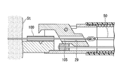
- FIG. 1 It is a perspective view showing the whole suture device composition concerning a first embodiment of the present invention. It is sectional drawing which shows the stitching
- FIG. 1 is a perspective view showing the overall configuration of the suturing device 1 of the present embodiment.
- the suturing device 1 includes a long insertion portion 10 having flexibility, a suturing portion 20 provided at a distal end portion of the insertion portion 10, an operation portion 40 provided at a proximal end portion of the insertion portion 10, and an insertion. Gripping forceps (thread gripping portion) 50 inserted through the portion 10.
- the insertion portion 10 is formed in a tubular shape with a coil, resin, or the like, and is inserted into the channel of the flexible endoscope.
- the insertion portion 10 has flexibility enough to follow a change in the shape of the channel when the flexible endoscope is used. A force that compresses in the axial direction acts on the insertion portion 10 when the stitching portion 20 is driven (described later). Therefore, it is preferable that the insertion part 20 has a structure excellent in compression resistance using a coil or the like made of a metal wire.
- FIG. 2 is a cross-sectional view of the stitched portion 20.
- the stitching portion 20 includes a tubular base body 21, a pressing base 22 attached to the base body 21, a crimping member (pressing member) 25 that is rotatably supported by the base body 21, and a driver for driving the crimping member 25. 30.
- the pressing table 22 has an installation surface 23 on which a pipe (anchor) 100 that is fixed to the suture in a state where the suture is inserted is installed.
- the caulking member 25 has a convex portion 26 provided at the distal end portion, a through hole 27 provided in the intermediate portion, and a drive projection 28 provided on the proximal end side.
- the caulking member 25 is supported so as to be rotatable relative to the base 21 and the pressing base 22 by inserting a rotation shaft 21 a provided on the base 21 through the through hole 27.
- the convex portion 26 has a ridge line 26a extending in one direction.
- a shaft hole (through portion) 29 extending in a direction perpendicular to the through hole 27 is provided on the opposite side of the convex portion 26 across the through hole 27.
- the shaft hole 29 is open at both ends and has an inner diameter through which the grasping forceps 50 can be inserted.
- the drive protrusion 28 protrudes at a position farther from the through hole 27 than the shaft hole 29.
- the driver 30 has a hard main body 31 and a wire (operation member) 32 for driving the main body 31.
- the main body 31 has such a rigidity that the caulking member 25 can be rotated when the drive protrusion 28 is overcome (described later).
- the wire 32 extends through the insertion unit 10 to the operation unit 40.
- the operation unit 40 includes a handle 41 for driving the driver 30 and a forceps port 42 into which the grasping forceps 50 are inserted.
- a wire 32 is connected to the handle 41, and the main body 31 of the driver 30 can be moved in a direction approaching the operation unit 40 by grasping the handle 42.
- the gripping forceps 50 includes a gripping part 51 composed of a pair of jaws and a slider 52 for opening and closing the gripping part 51.
- the basic structure of the grasping forceps 50 is the same as that of a general grasping forceps that is used by being inserted into a flexible endoscope.
- the grasping forceps 50 has a size that can be inserted into the forceps opening 42, the shaft hole 29 of the caulking member 25, and the pipe 100, and is formed smaller than a general grasping forceps.
- the operator introduces a flexible endoscope into the patient's luminal organ, and uses a suture unit in which a suture needle is attached to one end of the suture thread. Thread the thread. Threading can be performed using a known suture instrument that is inserted into a flexible endoscope.
- known suture devices include a suture device having a structure in which a suture needle is transferred between a pair of jaws, and a suture device having a structure for driving a curved needle.
- the pipe 100 is installed on the installation surface 23 of the pressing table 22.
- the pipe 100 preferably has a radial dimension shorter than that of the ridge line 26 a and the V groove 24.
- a material of the pipe 100 a plastically deformable material such as a metal or a resin can be used, and a material having high biocompatibility such as titanium or stainless steel is preferable.
- the pipe 100 is preferably installed so that the axial direction of the pipe 100 and the extending direction of the V-groove 24 are orthogonal to each other.
- the operator After installing the pipe 100, the operator inserts the suturing device 1 into the channel of the flexible endoscope. Subsequently, the grasping forceps 50 is inserted into the forceps opening 42. The grasping forceps 50 may be inserted into the forceps opening 42 before the suturing device 1 is inserted into the flexible endoscope.
- the shaft hole 29 of the caulking member 25 and the lumen of the pipe 100 are coaxial (substantially coaxial, including the same hereinafter). They are in a positional relationship and are aligned in the same straight line. Therefore, the grasping forceps 50 inserted into the forceps opening 42 can easily pass through the shaft hole 29 and the pipe 100 and cause the grasping portion 51 to protrude from the pipe 100.
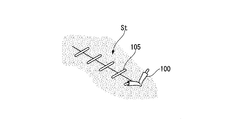
- the surgeon brings the suturing device 1 in a state in which the grasping portion 51 protrudes from the pipe 100 close to the target tissue St, and as shown in FIG. 3, the end portion of the suture 105 hung on the target tissue St is grasped. Grip with Subsequently, the grasping forceps 50 are pulled toward the proximal side, and the grasping forceps 50 are removed from the pipe 100 and the shaft hole 29. By this operation, the suture thread 105 is inserted into the pipe 100 and the shaft hole 29 as shown in FIG.
- the surgeon pulls the grasping forceps 50 that grasps the suture thread 105 to the proximal side while pressing the distal end of the suturing device 1 against the target tissue St.
- the opening of the target tissue St to be closed is closed by suturing, and the tension applied to the target tissue St by the suture thread 105 is adjusted to a desired size.
- the operator holds the handle 41 while holding the tension and drives the driver 30.
- the handle 41 is gripped, the wire 32 is pulled toward the hand side, and the main body 31 moves in a direction approaching the operation unit 40 and first contacts the drive protrusion 28 of the caulking member 25.
- the main body 31 pushes the drive protrusion 28.
- the caulking member 25 rotates about the rotation shaft 21a, and the convex portion 26 facing the installation surface 23 approaches the pipe 100 and comes into contact therewith.
- the pipe 100 is sandwiched between the convex portion 26 and the installation surface 23.
- a pressing force is applied to the pipe 100 from the ridge line 26a, and the pipe 100 is bent with a portion where the ridge line 26a contacts as a fold line as shown in FIG. A part of the bent pipe 100 enters the V groove 24, and the pipe 100 is deformed.
- the pipe 100 is caulked so that the suture thread 105 inserted through the pipe 100 contacts the inner surface of the pipe 100, and the pipe 100 is fixed to the suture thread 105.
- Fig. 6 shows a deformed pipe 100.
- the straight pipe 100 is sandwiched between the pressing table 22 and the caulking member 25 and is subjected to a force from the convex portion 26, so that the ridge line 26a is in contact with the fold line 101 on the tip side.
- the axis X1 of the one region 102 and the axis X2 of the second region 103 on the base end side with respect to the fold line 101 form an angle and are caulked and deformed into a non-parallel substantially V shape.
- the pipe 100 fixed to the suture thread 105 does not enter the target tissue St as shown in FIG. 8, it is hung on the target tissue St in the same manner as the last knot formed in a general surgical knot.
- the loosened suture 105 is prevented from loosening.
- the state in which the suture 105 applies a desired tension to the target tissue St is preferably held.
- the axis X1 of the first region 102 and the axis X2 of the second region 103 on the proximal end side of the pipe 100 through which the suture thread 105 is inserted are not parallel.
- the suture 105 and the pipe 100 are fixed by caulking so as to be deformed into a substantially V shape. Therefore, the suture thread 105 is bent in a substantially V shape along the axis line X1 and the axis line X2 in the pipe 100, and is pressed against a portion of the inner surface of the pipe 100 that protrudes inward at the bent portion.
- the pressing base 22 and the caulking member 25 that are caulked and deformed with the pipe 100 interposed therebetween are respectively formed with corresponding V grooves 24 and convex portions 26. For this reason, it can deform
- FIG. since the length of the V groove 24 and the convex part 26 is longer than the outer diameter of the pipe 100, the pipe 100 can be pressed over the radial direction, and can be suitably bent and deformed into a substantially V shape.
- the driver 30 for driving the caulking member 25 is driven by pulling the wire 32 connected to the operation unit 40.
- an operation member such as a wire used for transmitting an operation force amount is likely to buckle when being pushed in, and it is not easy to suitably transmit the force amount by a pressing operation.
- the amount of power can be transmitted suitably. Therefore, even if the insertion portion 10 has a soft structure, a sufficient amount of force can be generated to drive the caulking member 25 and sewing can be performed easily. This effect becomes more remarkable by increasing the compression resistance of the insertion portion 10.
- the grasping forceps 50 can be inserted into the pipe 100 or the suture thread 105 can be inserted into the pipe 100 simply by moving the grasping forceps 50 forward and backward. Can be performed easily.
- the caulking member 25 has the shaft hole 29 and the pipe 100 and the shaft hole 29 are in the same linear relationship in the initial state, the gripping forceps 50 inserted into the insertion portion 10 is merely advanced. Thus, the shaft hole 29 and the pipe 100 can be easily inserted.
- the aspect of holding the pipe 100 on the installation surface 23 is not particularly limited.
- the pipe 100 may be held between the caulking member 25 and the pressing base 22, or the pipe 100 may be temporarily fixed on the installation surface 23 with an adhesive or the like. May be held.
- the position on the installation surface 23 of the pipe 100 may be stabilized by providing a shallow groove orthogonal to the V-groove 24 on the installation surface 23 and disposing it in this groove.
- the form of the penetrating part may be a bowl shape in which the inner surface is not continuous in the circumferential direction in addition to the shape like the shaft hole 29 described above.
- FIG. 9 The difference between the suturing device 151 of the present embodiment and the suturing device 1 of the first embodiment is the configuration of the suturing portion.
- components that are the same as those already described are assigned the same reference numerals and redundant description is omitted.
- FIG. 9 is a cross-sectional view showing the suturing portion 160 of the suturing device 151.
- a part of the inner surface of the tubular base body 161 is formed flat and serves as an installation surface 161a.
- a screw shaft 162 having a thread groove formed in the outer peripheral surface thereof is disposed in the base body 161 so as to pass therethrough.
- Pulleys 163 are fixed to both ends of the screw shaft 162 protruding on the outer peripheral surface of the base body 161, and an annularly connected wire 164 is wound around each pulley 163.
- the wire 164 extends along the insertion portion 10 and is attached to an operation pulley (not shown) provided in an operation portion (not shown).
- a rod-shaped guide 165 is attached in parallel with the screw shaft 162.
- the crimping member 166 has the convex part 26 similarly to 1st embodiment.
- a first through hole 167 in which a thread groove is cut and a second through hole 168 having no screw groove are provided on the base end side from the convex portion 26.
- the caulking member 166 is disposed in the base body 161 such that the screw shaft 162 is inserted into the first through hole 167 and the guide 165 is inserted into the second through hole 168.
- the screw shaft 162, the pulley 163, the wire 164, and the guide 165 cooperate to function as the driver 169.
- the pipe 100 is temporarily fixed to the installation surface 161a by adhesion or the like, and the suture 105 is inserted into the pipe 100 using the grasping forceps 50 (not shown) by the same operation as in the first embodiment.
- the operator pulls the wire 164 by turning the operation pulley in a predetermined direction.
- the pulley 163 and the screw shaft 162 rotate.
- the guide 165 is inserted into the caulking member 166, the screw shaft 162 and the caulking member 166 do not rotate integrally but rotate relative to each other.
- the caulking member 166 moves upward by screw fitting and approaches the installation surface 161a.
- the convex portion 26 comes into contact with the pipe 100, and the pipe 100 is pressed and caulked and deformed into a substantially V shape.
- the caulking member 166 moves downward when the operation pulley is rotated in the opposite direction.
- the suturing device 151 is retracted in this state, the pipe 100 is detached from the installation surface 161a.
- the caulking member 165 is driven by pulling the wire 164, even if the insertion portion has a soft structure, it is simple as in the suturing device 1 of the first embodiment. Can be sutured.
- FIG. 10 shows a modification of this embodiment.
- FIG. 10 is a cross-sectional view showing a suturing portion 180 of a suturing apparatus 171 according to a modification.
- a pressing table 172 having an inclined surface 172a is attached inside the tubular base body 161.
- the slope 172a that functions as an installation surface faces the distal end side of the stitching portion 180, and the pipe 100 is held on the slope 172a by adhesion or locking.
- the caulking member 173 having the convex portion 174 is disposed on the tip side of the pressing base 172 with the convex portion 174 facing the slope 172a.
- a screw shaft 176 is inserted into a through hole 175 provided in the caulking member 173, and the caulking member 173 and the screw shaft 176 are screw-fitted.
- the screw shaft 176 extends in parallel with the axis of the base body 161.
- the proximal end portion of the screw shaft 176 is connected to the distal end portion of the coil shaft 177 in the insertion portion 10 close to the base body 161.
- the coil shaft 177 extends through the insertion portion 10 to an operation portion (not shown).
- the screw shaft 176 is rotated around the axis.
- the caulking member 173 moves relative to the screw shaft 176, and the convex portion 174 approaches the pipe 100 held by the pressing table 172.
- the convex part 174 contacts the pipe 100 and presses the pipe 100, and the pipe 100 is caulked and deformed into a substantially V shape. Since the coil shaft 177 has flexibility, the coil shaft 177 can suitably follow the bending and meandering of the insertion portion 10.
- the suturing device 171 of this embodiment similarly to the other embodiments, it is possible to simply perform suturing even if the insertion portion has a soft structure.
- the screw shaft 176 and the coil shaft 177 that function as the driver 178 are arranged in the insertion portion 10 along the longitudinal direction of the insertion portion 10, the diameter of the suture portion can be made smaller than that of the suturing device 151 described above. It is.
- a concave portion may be provided on the inclined surface 172a of the suturing device 171 of the modified example, or the concave portion may be omitted in other embodiments.
- a groove having a bottom portion formed in a curved surface may be used instead of the V groove having the deepest portion extending linearly.
Abstract
This suture device is provided with: a flexible tubular insertion section; a suture section provided at the front end of the insertion section and holding a tubular anchor into which a suture thread is insertable; an operating section provided at the base end of the insertion section; and a thread gripping section inserted through the insertion section and configured to be insertable into the anchor. The suture section has: a mounting surface on which the anchor is held; a pressing member having a protrusion for pressing the anchor and disposed so that the protrusion will face the mounting surface; and a driver connected to the operating section and actuating the pressing member. The suture device is configured so that driving the driver will cause the anchor to be gripped between the mounting surface and the protrusion and pressed, thereby deforming the anchor into a substantially V-shape.
Description
本発明は、医療用の縫合装置に関する。
本願は、2015年8月4日に、日本に出願された特願2015-153844号に基づき優先権を主張し、その内容をここに援用する。 The present invention relates to a medical suturing device.
This application claims priority based on Japanese Patent Application No. 2015-153844 filed in Japan on August 4, 2015, the contents of which are incorporated herein by reference.
従来、消化管等の管腔臓器に挿入した軟性内視鏡を用いて、様々な処置が行われている。一般にこれらの処置は、内視鏡挿入部に設けられたチャンネルに内視鏡用処置具を挿通し、処置具の先端を内視鏡挿入部の先端から突出させて行われる。
Conventionally, various treatments have been performed using a flexible endoscope inserted into a luminal organ such as the digestive tract. In general, these treatments are performed by inserting an endoscope treatment tool through a channel provided in the endoscope insertion portion and projecting the distal end of the treatment tool from the distal end of the endoscope insertion portion.
難度が高い処置の一つとして、縫合糸を用いた縫合がある。縫合という一連の手技は、組織に縫合糸を掛ける動作と、組織に掛けた縫合糸が、組織に所定のテンションを掛け続けるように縫合糸に結び目を形成する動作とを含む。より難度が高いのは後者であり、処置具を用いて行うことは容易ではない。
One of the difficult treatments is suturing using sutures. A series of procedures called suturing includes an operation of applying a suture to the tissue and an operation of forming a knot on the suture so that the suture applied to the tissue keeps applying a predetermined tension to the tissue. The latter is more difficult, and it is not easy to perform using a treatment instrument.
そこで結び目を形成するのに代えて、縫合糸とは別の糸止め部材を縫合糸に固定することにより結び目と同等の機能を発揮させることが提案されている。このような縫合装置として、特許文献1に記載の医療用縫合器が知られている。
Therefore, instead of forming a knot, it has been proposed to exhibit a function equivalent to that of a knot by fixing a thread fixing member different from the suture to the suture. As such a suturing device, a medical suturing device described in Patent Document 1 is known.
しかしながら、特許文献1に記載の医療用縫合器は、押圧部材を前進させて糸止め部材を押圧することにより縫合糸に固定している。これは、硬質な挿入部を備える特許文献1に記載のような構造では問題ないが、軟性内視鏡に挿通される、可撓性の挿入部を備えた軟性の処置具においては諸々の事情により現実的ではない。
However, the medical suturing device described in Patent Document 1 is fixed to the suture by advancing the pressing member and pressing the thread fixing member. This is not a problem with the structure described in Patent Document 1 including a hard insertion portion, but various circumstances are involved in a flexible treatment instrument including a flexible insertion portion that is inserted through a flexible endoscope. Is not realistic.
上記事情を踏まえ、本発明は、軟性の挿入部を備えた構成でありながら、縫合を簡便に行うことができる縫合装置を提供することを目的とする。
In view of the above circumstances, an object of the present invention is to provide a suturing apparatus that can easily perform suturing while having a structure including a soft insertion portion.
本発明は、可撓性を有する管状の挿入部と、前記挿入部の先端部に設けられ、縫合糸を挿通可能な管状のアンカーが保持される縫合部と、前記挿入部の基端部に設けられた操作部と、前記挿入部に挿通され、前記アンカーに挿通可能に構成された糸把持部とを備え、前記縫合部は、前記アンカーが保持される設置面と、前記アンカーを押圧する凸部を有し、前記凸部が前記設置面に対向するように配置された押圧部材と、前記操作部と接続され、前記押圧部材を作動させるためのドライバと、を有し、前記ドライバを駆動することにより、前記アンカーが、前記設置面と前記凸部との間に挟まれて押圧され、略V字状に変形されるように構成されている縫合装置である。
The present invention provides a tubular insertion portion having flexibility, a suture portion provided at a distal end portion of the insertion portion and holding a tubular anchor through which a suture thread can be inserted, and a proximal end portion of the insertion portion. An operation portion provided; and a thread gripping portion that is inserted into the insertion portion and configured to be able to pass through the anchor. The stitching portion presses the anchor and an installation surface on which the anchor is held. A pressing member that has a convex portion, and is arranged so that the convex portion faces the installation surface; and a driver that is connected to the operation unit and operates the pressing member. The suturing device is configured such that when driven, the anchor is sandwiched and pressed between the installation surface and the convex portion and deformed into a substantially V-shape.
前記凸部は、一方向に延び、かつ長手方向の寸法が前記アンカーの外径よりも大きく、前記設置面は、前記凸部が進入可能な凹部を有してもよい。
The convex portion may extend in one direction and have a longitudinal dimension larger than the outer diameter of the anchor, and the installation surface may have a concave portion into which the convex portion can enter.
前記ドライバは、前記操作部と接続される操作部材を有し、前記操作部で前記操作部材が牽引されることにより駆動する構成であってもよい。
The driver may have an operation member connected to the operation unit, and may be driven by being pulled by the operation unit.
前記押圧部材は、前記糸把持部を挿通可能な貫通部を有し、前記ドライバが駆動される前の初期状態において、前記アンカーの内腔と前記貫通部とが同一直線上に並ぶように構成されてもよい。
The pressing member has a penetrating portion through which the thread gripping portion can be inserted, and is configured so that the lumen of the anchor and the penetrating portion are aligned on the same straight line in an initial state before the driver is driven. May be.
上記各態様の縫合装置によれば、軟性の挿入部を備えた構成でありながら、縫合を簡便に行うことができる。
According to the suturing device of each aspect described above, it is possible to easily perform suturing while having a configuration including a soft insertion portion.
本発明の第一実施形態について、図1から図8を参照して説明する。図1は、本実施形態の縫合装置1の全体構成を示す斜視図である。縫合装置1は、可撓性を有する長尺の挿入部10と、挿入部10の先端部に設けられた縫合部20と、挿入部10の基端部に設けられた操作部40と、挿入部10に挿通される把持鉗子(糸把持部)50とを備えている。
A first embodiment of the present invention will be described with reference to FIGS. FIG. 1 is a perspective view showing the overall configuration of the suturing device 1 of the present embodiment. The suturing device 1 includes a long insertion portion 10 having flexibility, a suturing portion 20 provided at a distal end portion of the insertion portion 10, an operation portion 40 provided at a proximal end portion of the insertion portion 10, and an insertion. Gripping forceps (thread gripping portion) 50 inserted through the portion 10.
挿入部10は、コイルや樹脂等で管状に形成され、軟性内視鏡のチャンネルに挿通される。挿入部10は、軟性内視鏡の使用時におけるチャンネルの形状変化に追従できる程度の可撓性を有する。挿入部10には、縫合部20の駆動時(後述)に、軸線方向に圧縮する力が作用する。そのため、挿入部20は、金属素線からなるコイル等を用いて耐圧縮性に優れた構造を有するのが好ましい。
The insertion portion 10 is formed in a tubular shape with a coil, resin, or the like, and is inserted into the channel of the flexible endoscope. The insertion portion 10 has flexibility enough to follow a change in the shape of the channel when the flexible endoscope is used. A force that compresses in the axial direction acts on the insertion portion 10 when the stitching portion 20 is driven (described later). Therefore, it is preferable that the insertion part 20 has a structure excellent in compression resistance using a coil or the like made of a metal wire.
図2は、縫合部20の断面図である。縫合部20は、管状の基体21と、基体21に取り付けられた押し付け台22と、基体21に回動可能に支持されたカシメ部材(押圧部材)25と、カシメ部材25を駆動するためのドライバ30とを備えている。
FIG. 2 is a cross-sectional view of the stitched portion 20. The stitching portion 20 includes a tubular base body 21, a pressing base 22 attached to the base body 21, a crimping member (pressing member) 25 that is rotatably supported by the base body 21, and a driver for driving the crimping member 25. 30.
押し付け台22は、縫合糸が挿通された状態で縫合糸に固定されるパイプ(アンカー)100が設置される設置面23を有する。設置面23には、基体21の軸線方向と直角をなす方向に延びるV溝(凹部)24が形成されている。
The pressing table 22 has an installation surface 23 on which a pipe (anchor) 100 that is fixed to the suture in a state where the suture is inserted is installed. A V-groove (concave portion) 24 extending in a direction perpendicular to the axial direction of the base body 21 is formed on the installation surface 23.
カシメ部材25は、先端部に設けられた凸部26と、中間部に設けられた貫通孔27と、基端側に設けられた駆動突起28とを有する。カシメ部材25は、基体21に設けられた回動軸21aが貫通孔27に挿通されることにより、基体21および押し付け台22に対して相対回動可能に支持されている。凸部26は、一方向に延びる稜線26aを有する。カシメ部材25を回動軸21aを中心に回動させて凸部26をV溝24に接近させると、稜線26aの延びる方向とV溝24の延びる方向とが略一致し、稜線26aをV溝24内に進入させることができる。
カシメ部材25において、貫通孔27を挟んで凸部26と反対側には、貫通孔27と直角をなす方向に延びる軸孔(貫通部)29が設けられている。軸孔29は、両端が開口しており、把持鉗子50を挿通することができる内径を有する。駆動突起28は、軸孔29よりも貫通孔27から離れた位置に突出している。 Thecaulking member 25 has a convex portion 26 provided at the distal end portion, a through hole 27 provided in the intermediate portion, and a drive projection 28 provided on the proximal end side. The caulking member 25 is supported so as to be rotatable relative to the base 21 and the pressing base 22 by inserting a rotation shaft 21 a provided on the base 21 through the through hole 27. The convex portion 26 has a ridge line 26a extending in one direction. When the caulking member 25 is rotated about the rotation shaft 21a and the convex portion 26 is brought close to the V-groove 24, the extending direction of the ridge line 26a and the extending direction of the V-groove 24 substantially coincide with each other. 24 can be entered.
In thecaulking member 25, a shaft hole (through portion) 29 extending in a direction perpendicular to the through hole 27 is provided on the opposite side of the convex portion 26 across the through hole 27. The shaft hole 29 is open at both ends and has an inner diameter through which the grasping forceps 50 can be inserted. The drive protrusion 28 protrudes at a position farther from the through hole 27 than the shaft hole 29.
カシメ部材25において、貫通孔27を挟んで凸部26と反対側には、貫通孔27と直角をなす方向に延びる軸孔(貫通部)29が設けられている。軸孔29は、両端が開口しており、把持鉗子50を挿通することができる内径を有する。駆動突起28は、軸孔29よりも貫通孔27から離れた位置に突出している。 The
In the
ドライバ30は、硬質の本体31と、本体31を駆動するためのワイヤ(操作部材)32とを有する。本体31は、駆動突起28を乗り越える(後述)際にカシメ部材25を回動させることができる程度の剛性を有する。ワイヤ32は、挿入部10内を通って操作部40まで延びている。
The driver 30 has a hard main body 31 and a wire (operation member) 32 for driving the main body 31. The main body 31 has such a rigidity that the caulking member 25 can be rotated when the drive protrusion 28 is overcome (described later). The wire 32 extends through the insertion unit 10 to the operation unit 40.
操作部40は、図1に示すように、ドライバ30を駆動するためのハンドル41と、把持鉗子50が挿入される鉗子口42とを有する。ハンドル41にはワイヤ32が接続されており、ハンドル42を握ることで、ドライバ30の本体31を操作部40に接近する方向に移動させることができる。
1, the operation unit 40 includes a handle 41 for driving the driver 30 and a forceps port 42 into which the grasping forceps 50 are inserted. A wire 32 is connected to the handle 41, and the main body 31 of the driver 30 can be moved in a direction approaching the operation unit 40 by grasping the handle 42.
把持鉗子50は、一対のジョーからなる把持部51と、把持部51を開閉するためのスライダ52とを備えている。把持鉗子50の基本構造は、軟性内視鏡に挿通して使用する一般的な把持鉗子と同一であり、公知である。把持鉗子50は、鉗子口42、カシメ部材25の軸孔29、およびパイプ100に挿通可能な寸法を有しており、一般的な把持鉗子よりも小さく形成されている。
The gripping forceps 50 includes a gripping part 51 composed of a pair of jaws and a slider 52 for opening and closing the gripping part 51. The basic structure of the grasping forceps 50 is the same as that of a general grasping forceps that is used by being inserted into a flexible endoscope. The grasping forceps 50 has a size that can be inserted into the forceps opening 42, the shaft hole 29 of the caulking member 25, and the pipe 100, and is formed smaller than a general grasping forceps.
上記のように構成された本実施形態の縫合装置1の使用時の動作について説明する。まず術者は、軟性内視鏡を患者の管腔臓器内に導入し、縫合糸の一端に縫合針が取り付けられた縫合ユニットを用いて、縫合針を対象組織に通して縫合糸を対象組織に掛ける糸掛けを行う。糸掛けは、軟性内視鏡に挿通して使用する公知の縫合器を用いて行うことができる。公知の縫合器としては、一対のジョー間で縫合針を受け渡す構造の縫合器や、曲針を駆動する構造の縫合器などを例示することができる。
The operation at the time of use of the suturing device 1 of the present embodiment configured as described above will be described. First, the operator introduces a flexible endoscope into the patient's luminal organ, and uses a suture unit in which a suture needle is attached to one end of the suture thread. Thread the thread. Threading can be performed using a known suture instrument that is inserted into a flexible endoscope. Examples of known suture devices include a suture device having a structure in which a suture needle is transferred between a pair of jaws, and a suture device having a structure for driving a curved needle.
糸掛けが終了したら、術者は縫合針を縫合糸から切り離し、糸掛けに用いた縫合器を軟性内視鏡から抜去する。次に、押し付け台22の設置面23上にパイプ100を設置する。パイプ100としては、径方向の寸法が稜線26aおよびV溝24よりも短いものが好ましい。パイプ100の材質としては、金属や樹脂などの塑性変形可能なものを用いることができ、チタンやステンレス鋼など、生体適合性の高いものが好ましい。パイプ100は、パイプ100の軸線方向とV溝24の延びる方向とが直交するように設置するのが好ましい。
パイプ100を設置した後、術者は縫合装置1を軟性内視鏡のチャンネル内に挿入する。続いて、把持鉗子50を鉗子口42に挿入する。把持鉗子50は、縫合装置1を軟性内視鏡に挿入する前に鉗子口42に挿入しておいてもよい。 When the threading is completed, the operator cuts the suture needle from the suture, and removes the suture instrument used for threading from the flexible endoscope. Next, thepipe 100 is installed on the installation surface 23 of the pressing table 22. The pipe 100 preferably has a radial dimension shorter than that of the ridge line 26 a and the V groove 24. As a material of the pipe 100, a plastically deformable material such as a metal or a resin can be used, and a material having high biocompatibility such as titanium or stainless steel is preferable. The pipe 100 is preferably installed so that the axial direction of the pipe 100 and the extending direction of the V-groove 24 are orthogonal to each other.
After installing thepipe 100, the operator inserts the suturing device 1 into the channel of the flexible endoscope. Subsequently, the grasping forceps 50 is inserted into the forceps opening 42. The grasping forceps 50 may be inserted into the forceps opening 42 before the suturing device 1 is inserted into the flexible endoscope.
パイプ100を設置した後、術者は縫合装置1を軟性内視鏡のチャンネル内に挿入する。続いて、把持鉗子50を鉗子口42に挿入する。把持鉗子50は、縫合装置1を軟性内視鏡に挿入する前に鉗子口42に挿入しておいてもよい。 When the threading is completed, the operator cuts the suture needle from the suture, and removes the suture instrument used for threading from the flexible endoscope. Next, the
After installing the
縫合装置1において、ドライバ30を駆動する前の初期状態では、図2に示すように、カシメ部材25の軸孔29とパイプ100の内腔とが同軸(略同軸を含む。以下同様。)な位置関係にあり、同一直線状に並んでいる。したがって、鉗子口42に挿入した把持鉗子50は、軸孔29およびパイプ100を容易に通過させてパイプ100から把持部51を突出させることができる。
In the initial state before the driver 30 is driven in the suturing device 1, as shown in FIG. 2, the shaft hole 29 of the caulking member 25 and the lumen of the pipe 100 are coaxial (substantially coaxial, including the same hereinafter). They are in a positional relationship and are aligned in the same straight line. Therefore, the grasping forceps 50 inserted into the forceps opening 42 can easily pass through the shaft hole 29 and the pipe 100 and cause the grasping portion 51 to protrude from the pipe 100.
術者は、把持部51がパイプ100から突出した状態の縫合装置1を対象組織Stに接近させ、図3に示すように、対象組織Stに掛けられた縫合糸105の端部を把持部51で把持する。続いて、把持鉗子50を手元側に引き寄せ、パイプ100および軸孔29から把持鉗子50を抜去する。この操作により、図4に示すように、縫合糸105がパイプ100および軸孔29に挿通される。
The surgeon brings the suturing device 1 in a state in which the grasping portion 51 protrudes from the pipe 100 close to the target tissue St, and as shown in FIG. 3, the end portion of the suture 105 hung on the target tissue St is grasped. Grip with Subsequently, the grasping forceps 50 are pulled toward the proximal side, and the grasping forceps 50 are removed from the pipe 100 and the shaft hole 29. By this operation, the suture thread 105 is inserted into the pipe 100 and the shaft hole 29 as shown in FIG.
次に、術者は、縫合装置1の先端を対象組織Stに押し当てつつ縫合糸105を把持した把持鉗子50を手元側に牽引する。この操作により、縫合によって閉じるべき対象組織Stの開口を閉じるとともに、縫合糸105が対象組織Stにかけるテンションを所望の大きさに調節する。
続いて術者は、テンションを保持しつつハンドル41を握り、ドライバ30を駆動する。ハンドル41が握られるとワイヤ32が手元側に牽引され、本体31が操作部40に接近する方向に移動して、まずカシメ部材25の駆動突起28に接触する。ワイヤ32がさらに牽引されると、本体31が駆動突起28を押す。その結果、カシメ部材25は、回動軸21aを中心に回動し、設置面23に対向する凸部26がパイプ100に接近して接触する。この動作により、パイプ100は、凸部26と設置面23との間に挟まれる。さらに、稜線26aからパイプ100に押圧力が加えられ、パイプ100は、図5に示すように、稜線26aが接触した部位を折り線として折り曲げられる。折り曲げられたパイプ100の一部は、V溝24内に進入し、パイプ100が変形される。
その結果、パイプ100に挿通された縫合糸105がパイプ100の内面と接触するようにパイプ100がかしめられ、パイプ100が縫合糸105に対して固定される。 Next, the surgeon pulls the graspingforceps 50 that grasps the suture thread 105 to the proximal side while pressing the distal end of the suturing device 1 against the target tissue St. By this operation, the opening of the target tissue St to be closed is closed by suturing, and the tension applied to the target tissue St by the suture thread 105 is adjusted to a desired size.
Subsequently, the operator holds thehandle 41 while holding the tension and drives the driver 30. When the handle 41 is gripped, the wire 32 is pulled toward the hand side, and the main body 31 moves in a direction approaching the operation unit 40 and first contacts the drive protrusion 28 of the caulking member 25. When the wire 32 is further pulled, the main body 31 pushes the drive protrusion 28. As a result, the caulking member 25 rotates about the rotation shaft 21a, and the convex portion 26 facing the installation surface 23 approaches the pipe 100 and comes into contact therewith. By this operation, the pipe 100 is sandwiched between the convex portion 26 and the installation surface 23. Further, a pressing force is applied to the pipe 100 from the ridge line 26a, and the pipe 100 is bent with a portion where the ridge line 26a contacts as a fold line as shown in FIG. A part of the bent pipe 100 enters the V groove 24, and the pipe 100 is deformed.
As a result, thepipe 100 is caulked so that the suture thread 105 inserted through the pipe 100 contacts the inner surface of the pipe 100, and the pipe 100 is fixed to the suture thread 105.
続いて術者は、テンションを保持しつつハンドル41を握り、ドライバ30を駆動する。ハンドル41が握られるとワイヤ32が手元側に牽引され、本体31が操作部40に接近する方向に移動して、まずカシメ部材25の駆動突起28に接触する。ワイヤ32がさらに牽引されると、本体31が駆動突起28を押す。その結果、カシメ部材25は、回動軸21aを中心に回動し、設置面23に対向する凸部26がパイプ100に接近して接触する。この動作により、パイプ100は、凸部26と設置面23との間に挟まれる。さらに、稜線26aからパイプ100に押圧力が加えられ、パイプ100は、図5に示すように、稜線26aが接触した部位を折り線として折り曲げられる。折り曲げられたパイプ100の一部は、V溝24内に進入し、パイプ100が変形される。
その結果、パイプ100に挿通された縫合糸105がパイプ100の内面と接触するようにパイプ100がかしめられ、パイプ100が縫合糸105に対して固定される。 Next, the surgeon pulls the grasping
Subsequently, the operator holds the
As a result, the
図6に変形したパイプ100を示す。直線状であったパイプ100は、押し付け台22とカシメ部材25との間に挟まれて凸部26から力が加えられることにより、稜線26aが接触していた折り曲げ線101よりも先端側の第一領域102の軸線X1と、折り曲げ線101よりも基端側の第二領域103の軸線X2とが角度をなし、非平行な略V字状にかしめ変形される。
Fig. 6 shows a deformed pipe 100. The straight pipe 100 is sandwiched between the pressing table 22 and the caulking member 25 and is subjected to a force from the convex portion 26, so that the ridge line 26a is in contact with the fold line 101 on the tip side. The axis X1 of the one region 102 and the axis X2 of the second region 103 on the base end side with respect to the fold line 101 form an angle and are caulked and deformed into a non-parallel substantially V shape.
ワイヤ32がさらに牽引されると、本体31は、図7に示すように、カシメ部材25の回動により移動した駆動突起28を乗り越えて、駆動突起28よりも操作部40寄りの位置に移動する。この状態では、カシメ部材25の回動はドライバ30により規制されないため、縫合装置1を対象組織Stから後退させると、パイプ100が縫合糸105とともに縫合部20から外れる。最後にパイプ100から突出した余分な縫合糸を切り取ると、一連の処置が終了する。
When the wire 32 is further pulled, as shown in FIG. 7, the main body 31 moves over the drive protrusion 28 moved by the rotation of the caulking member 25 and moves to a position closer to the operation unit 40 than the drive protrusion 28. . In this state, the rotation of the caulking member 25 is not restricted by the driver 30, and therefore, when the suturing device 1 is retracted from the target tissue St, the pipe 100 is detached from the suturing portion 20 together with the suture thread 105. Finally, when the excess suture protruding from the pipe 100 is cut off, a series of treatments is completed.
縫合糸105に固定されたパイプ100は、図8に示すように、対象組織Stの内部には入らないため、一般的な外科結びにおいて最後に形成される結び目と同様に、対象組織Stに掛けられた縫合糸105が緩むのを防止する。その結果、縫合糸105が対象組織Stに所望のテンションを付与した状態が好適に保持される。
Since the pipe 100 fixed to the suture thread 105 does not enter the target tissue St as shown in FIG. 8, it is hung on the target tissue St in the same manner as the last knot formed in a general surgical knot. The loosened suture 105 is prevented from loosening. As a result, the state in which the suture 105 applies a desired tension to the target tissue St is preferably held.
以上説明したように、本実施形態の縫合装置1によれば、縫合糸105を挿通したパイプ100を第一領域102の軸線X1と、基端側の第二領域103の軸線X2とが非平行な略V字状に変形するようにかしめて縫合糸105とパイプ100とを固定する。このため、縫合糸105は、パイプ100内で軸線X1および軸線X2にならって略V字状に曲げられ、パイプ100の内面のうち、折り曲げ部位で内方に突出する部分に押し付けられる。その結果、縫合糸105とパイプ100との間に大きな摩擦が発生し、パイプの直線状形状を保ちつつ施すような一般的なかしめよりも確実に縫合糸105とパイプ100との固定を行うことができる。
したがって、縫合装置1によれば、術者が高度な技術を身につけなくても、縫合処置における結び目形成に相当する工程を簡便かつ確実に行うことができる。 As described above, according to thesuturing device 1 of the present embodiment, the axis X1 of the first region 102 and the axis X2 of the second region 103 on the proximal end side of the pipe 100 through which the suture thread 105 is inserted are not parallel. The suture 105 and the pipe 100 are fixed by caulking so as to be deformed into a substantially V shape. Therefore, the suture thread 105 is bent in a substantially V shape along the axis line X1 and the axis line X2 in the pipe 100, and is pressed against a portion of the inner surface of the pipe 100 that protrudes inward at the bent portion. As a result, a large friction is generated between the suture thread 105 and the pipe 100, and the suture thread 105 and the pipe 100 are fixed more securely than general caulking that is performed while maintaining the straight shape of the pipe. Can do.
Therefore, according to thesuturing apparatus 1, even if an operator does not acquire advanced techniques, a process corresponding to knot formation in the suturing treatment can be performed easily and reliably.
したがって、縫合装置1によれば、術者が高度な技術を身につけなくても、縫合処置における結び目形成に相当する工程を簡便かつ確実に行うことができる。 As described above, according to the
Therefore, according to the
また、パイプ100を挟んでかしめ変形させる押し付け台22およびカシメ部材25には、それぞれ対応するV溝24および凸部26が形成されている。このため、凸部26に押圧されたパイプ100の一部がV溝24内に落ち込むように変形することで、好適に略V字状に変形させることができる。
さらに、V溝24および凸部26の長さがパイプ100の外径よりも長いため、パイプ100を径方向にわたって押圧することができ、好適に折り曲げて略V字状に変形させることができる。 Further, thepressing base 22 and the caulking member 25 that are caulked and deformed with the pipe 100 interposed therebetween are respectively formed with corresponding V grooves 24 and convex portions 26. For this reason, it can deform | transform suitably in a substantially V shape by deform | transforming so that a part of pipe 100 pressed by the convex part 26 may fall in the V groove 24. FIG.
Furthermore, since the length of theV groove 24 and the convex part 26 is longer than the outer diameter of the pipe 100, the pipe 100 can be pressed over the radial direction, and can be suitably bent and deformed into a substantially V shape.
さらに、V溝24および凸部26の長さがパイプ100の外径よりも長いため、パイプ100を径方向にわたって押圧することができ、好適に折り曲げて略V字状に変形させることができる。 Further, the
Furthermore, since the length of the
さらに、カシメ部材25を駆動するためのドライバ30は、操作部40に接続されたワイヤ32が牽引されることにより駆動される。軟性の処置具において、操作力量を伝達するために用いられるワイヤ等の操作部材は、押し込む際に座屈等を生じやすく、押圧操作で好適に力量を伝達することは容易でないが、牽引操作では好適に力量を伝達することができる。
したがって、挿入部10が軟性の構造であっても、カシメ部材25の駆動に十分な力量を発生させて簡便に縫合を行うことができる。この効果は、挿入部10の耐圧縮性を高めることでさらに顕著となる。 Furthermore, thedriver 30 for driving the caulking member 25 is driven by pulling the wire 32 connected to the operation unit 40. In a flexible treatment instrument, an operation member such as a wire used for transmitting an operation force amount is likely to buckle when being pushed in, and it is not easy to suitably transmit the force amount by a pressing operation. The amount of power can be transmitted suitably.
Therefore, even if theinsertion portion 10 has a soft structure, a sufficient amount of force can be generated to drive the caulking member 25 and sewing can be performed easily. This effect becomes more remarkable by increasing the compression resistance of the insertion portion 10.
したがって、挿入部10が軟性の構造であっても、カシメ部材25の駆動に十分な力量を発生させて簡便に縫合を行うことができる。この効果は、挿入部10の耐圧縮性を高めることでさらに顕著となる。 Furthermore, the
Therefore, even if the
加えて、パイプ100は、縫合装置1の長手方向と平行に配置されるため、把持鉗子50を進退させるだけで、パイプ100への把持鉗子50の挿通や、パイプ100への縫合糸105の挿通を簡便に行うことができる。
さらに、カシメ部材25が軸孔29を有し、かつ初期状態において、パイプ100と軸孔29とが同一直線状に並ぶ位置関係にあるため、挿入部10に挿入した把持鉗子50を前進させるだけで、軸孔29およびパイプ100に容易に挿通することができる。 In addition, since thepipe 100 is arranged in parallel with the longitudinal direction of the suturing device 1, the grasping forceps 50 can be inserted into the pipe 100 or the suture thread 105 can be inserted into the pipe 100 simply by moving the grasping forceps 50 forward and backward. Can be performed easily.
Further, since thecaulking member 25 has the shaft hole 29 and the pipe 100 and the shaft hole 29 are in the same linear relationship in the initial state, the gripping forceps 50 inserted into the insertion portion 10 is merely advanced. Thus, the shaft hole 29 and the pipe 100 can be easily inserted.
さらに、カシメ部材25が軸孔29を有し、かつ初期状態において、パイプ100と軸孔29とが同一直線状に並ぶ位置関係にあるため、挿入部10に挿入した把持鉗子50を前進させるだけで、軸孔29およびパイプ100に容易に挿通することができる。 In addition, since the
Further, since the
本実施形態において、パイプ100を設置面23上に保持する態様は特に限定されない。例えば、ドライバ30を軽く手元側に引くことにより、カシメ部材25と押し付け台22とでパイプ100を軽く挟んで保持してもよいし、パイプ100を粘着剤等により設置面23上に仮止めして保持してもよい。また、設置面23にV溝24と直交する浅い溝を設け、この溝内に配置することにより、パイプ100の設置面23上における位置を安定させてもよい。
In the present embodiment, the aspect of holding the pipe 100 on the installation surface 23 is not particularly limited. For example, by pulling the driver 30 lightly toward the hand side, the pipe 100 may be held between the caulking member 25 and the pressing base 22, or the pipe 100 may be temporarily fixed on the installation surface 23 with an adhesive or the like. May be held. Moreover, the position on the installation surface 23 of the pipe 100 may be stabilized by providing a shallow groove orthogonal to the V-groove 24 on the installation surface 23 and disposing it in this groove.
貫通部の態様は、上述した軸孔29のような形状の他、内面が周方向に連続しない樋状であってもよい。
The form of the penetrating part may be a bowl shape in which the inner surface is not continuous in the circumferential direction in addition to the shape like the shaft hole 29 described above.
次に、本発明の第二実施形態について、図9および図10を参照して説明する。本実施形態の縫合装置151と、第一実施形態の縫合装置1との異なるところは、縫合部の構成である。なお、以降の説明において、既に説明したものと共通する構成については、同一の符号を付して重複する説明を省略する。
Next, a second embodiment of the present invention will be described with reference to FIG. 9 and FIG. The difference between the suturing device 151 of the present embodiment and the suturing device 1 of the first embodiment is the configuration of the suturing portion. In the following description, components that are the same as those already described are assigned the same reference numerals and redundant description is omitted.
図9は、縫合装置151の縫合部160を示す断面図である。縫合部160においては、管状の基体161の内面の一部が平坦に形成され、設置面161aとなっている。基体161には、外周面にネジ溝が切られたネジ軸162が貫通するように配置されている。基体161の外周面上に突出したネジ軸162の両端部には、プーリ163が固定されており、各プーリ163には、環状に接続されたワイヤ164が巻き付けられている。ワイヤ164は、挿入部10に沿って延び操作部(不図示)に設けられた図示しない操作プーリに取り付けられている。
基体161の内部には、棒状のガイド165が、ネジ軸162と平行に取り付けられている。 FIG. 9 is a cross-sectional view showing thesuturing portion 160 of the suturing device 151. In the stitching portion 160, a part of the inner surface of the tubular base body 161 is formed flat and serves as an installation surface 161a. A screw shaft 162 having a thread groove formed in the outer peripheral surface thereof is disposed in the base body 161 so as to pass therethrough. Pulleys 163 are fixed to both ends of the screw shaft 162 protruding on the outer peripheral surface of the base body 161, and an annularly connected wire 164 is wound around each pulley 163. The wire 164 extends along the insertion portion 10 and is attached to an operation pulley (not shown) provided in an operation portion (not shown).
Inside thebase body 161, a rod-shaped guide 165 is attached in parallel with the screw shaft 162.
基体161の内部には、棒状のガイド165が、ネジ軸162と平行に取り付けられている。 FIG. 9 is a cross-sectional view showing the
Inside the
カシメ部材166は、第一実施形態と同様に凸部26を有する。凸部26より基端側には、ネジ溝が切られた第一貫通孔167と、ネジ溝を有さない第二貫通孔168とが設けられている。カシメ部材166は、ネジ軸162が第一貫通孔167とネジ嵌合するように挿通され、かつ第二貫通孔168にガイド165が挿通されるように基体161内に配置されている。
縫合部160においては、ネジ軸162、プーリ163、ワイヤ164、およびガイド165が協働してドライバ169として機能する。 The crimpingmember 166 has the convex part 26 similarly to 1st embodiment. A first through hole 167 in which a thread groove is cut and a second through hole 168 having no screw groove are provided on the base end side from the convex portion 26. The caulking member 166 is disposed in the base body 161 such that the screw shaft 162 is inserted into the first through hole 167 and the guide 165 is inserted into the second through hole 168.
In thestitching portion 160, the screw shaft 162, the pulley 163, the wire 164, and the guide 165 cooperate to function as the driver 169.
縫合部160においては、ネジ軸162、プーリ163、ワイヤ164、およびガイド165が協働してドライバ169として機能する。 The crimping
In the
縫合装置151の使用時は、パイプ100を粘着等により設置面161aに仮止めし、第一実施形態と同様の操作で、把持鉗子50(不図示)を用いて縫合糸105をパイプ100に挿通する。
次に術者は、操作プーリを所定の方向に回してワイヤ164を牽引する。これによりプーリ163およびネジ軸162が回転する。このとき、カシメ部材166にはガイド165が挿通されているため、ネジ軸162とカシメ部材166とは一体に回転せず、相対回転する。その結果、カシメ部材166は、ネジ嵌合により上方に移動して設置面161aに接近する。やがて、凸部26がパイプ100と接触してパイプ100が押圧され、略V字状にかしめ変形される。
パイプ100が変形されて縫合糸105に対して固定されたら、操作プーリを逆方向に回転すると、カシメ部材166が下方に移動する。この状態で縫合装置151を後退させると、パイプ100が設置面161aから外れる。 When thesuturing device 151 is used, the pipe 100 is temporarily fixed to the installation surface 161a by adhesion or the like, and the suture 105 is inserted into the pipe 100 using the grasping forceps 50 (not shown) by the same operation as in the first embodiment. To do.
Next, the operator pulls thewire 164 by turning the operation pulley in a predetermined direction. As a result, the pulley 163 and the screw shaft 162 rotate. At this time, since the guide 165 is inserted into the caulking member 166, the screw shaft 162 and the caulking member 166 do not rotate integrally but rotate relative to each other. As a result, the caulking member 166 moves upward by screw fitting and approaches the installation surface 161a. Eventually, the convex portion 26 comes into contact with the pipe 100, and the pipe 100 is pressed and caulked and deformed into a substantially V shape.
When thepipe 100 is deformed and fixed to the suture thread 105, the caulking member 166 moves downward when the operation pulley is rotated in the opposite direction. When the suturing device 151 is retracted in this state, the pipe 100 is detached from the installation surface 161a.
次に術者は、操作プーリを所定の方向に回してワイヤ164を牽引する。これによりプーリ163およびネジ軸162が回転する。このとき、カシメ部材166にはガイド165が挿通されているため、ネジ軸162とカシメ部材166とは一体に回転せず、相対回転する。その結果、カシメ部材166は、ネジ嵌合により上方に移動して設置面161aに接近する。やがて、凸部26がパイプ100と接触してパイプ100が押圧され、略V字状にかしめ変形される。
パイプ100が変形されて縫合糸105に対して固定されたら、操作プーリを逆方向に回転すると、カシメ部材166が下方に移動する。この状態で縫合装置151を後退させると、パイプ100が設置面161aから外れる。 When the
Next, the operator pulls the
When the
本実施形態の縫合装置151においても、ワイヤ164を牽引することによりカシメ部材165を駆動させる構成のため、第一実施形態の縫合装置1と同様、挿入部が軟性の構造であっても、簡便に縫合を行うことができる。
Also in the suturing device 151 of the present embodiment, since the caulking member 165 is driven by pulling the wire 164, even if the insertion portion has a soft structure, it is simple as in the suturing device 1 of the first embodiment. Can be sutured.
図10に、本実施形態の変形例を示す。図10は、変形例の縫合装置171の縫合部180を示す断面図である。管状の基体161の内部には、斜面172aを有する押し付け台172が取り付けられている。設置面として機能する斜面172aは縫合部180の先端側に向いており、パイプ100が粘着や係止等により斜面172a上に保持される。
FIG. 10 shows a modification of this embodiment. FIG. 10 is a cross-sectional view showing a suturing portion 180 of a suturing apparatus 171 according to a modification. A pressing table 172 having an inclined surface 172a is attached inside the tubular base body 161. The slope 172a that functions as an installation surface faces the distal end side of the stitching portion 180, and the pipe 100 is held on the slope 172a by adhesion or locking.
凸部174を有するカシメ部材173は、凸部174を斜面172a側に向けた状態で、押し付け台172よりも先端側に配置されている。カシメ部材173に設けられた貫通孔175には、ネジ軸176が挿通され、カシメ部材173とネジ軸176とがネジ嵌合している。
The caulking member 173 having the convex portion 174 is disposed on the tip side of the pressing base 172 with the convex portion 174 facing the slope 172a. A screw shaft 176 is inserted into a through hole 175 provided in the caulking member 173, and the caulking member 173 and the screw shaft 176 are screw-fitted.
ネジ軸176は基体161の軸線と平行に延びている。ネジ軸176の基端部は、基体161に近い挿入部10内でコイルシャフト177の先端部に接続されている。コイルシャフト177は、挿入部10内を通って操作部(不図示)まで延びている。
The screw shaft 176 extends in parallel with the axis of the base body 161. The proximal end portion of the screw shaft 176 is connected to the distal end portion of the coil shaft 177 in the insertion portion 10 close to the base body 161. The coil shaft 177 extends through the insertion portion 10 to an operation portion (not shown).
変形例の縫合装置171においては、操作部においてコイルシャフト177を軸線まわりの所定方向に回転させると、ネジ軸176が軸線まわりに回転する。その結果、カシメ部材173がネジ軸176に対して相対移動し、凸部174が押し付け台172に保持されたパイプ100に接近する。その後、凸部174がパイプ100と接触してパイプ100を押圧し、パイプ100が略V字状にかしめ変形される。
コイルシャフト177は、可撓性を有するため、挿入部10の湾曲や蛇行に好適に追従することができる。 In thesuturing device 171 of the modified example, when the coil shaft 177 is rotated in a predetermined direction around the axis in the operation portion, the screw shaft 176 is rotated around the axis. As a result, the caulking member 173 moves relative to the screw shaft 176, and the convex portion 174 approaches the pipe 100 held by the pressing table 172. Then, the convex part 174 contacts the pipe 100 and presses the pipe 100, and the pipe 100 is caulked and deformed into a substantially V shape.
Since thecoil shaft 177 has flexibility, the coil shaft 177 can suitably follow the bending and meandering of the insertion portion 10.
コイルシャフト177は、可撓性を有するため、挿入部10の湾曲や蛇行に好適に追従することができる。 In the
Since the
本実施形態の縫合装置171においても、他の実施形態と同様に、挿入部が軟性の構造であっても簡便に縫合を行うことができる。
また、ドライバ178として機能するネジ軸176およびコイルシャフト177が、挿入部10の長手方向に沿って挿入部10内に配置されているため、上述した縫合装置151よりも縫合部の小径化が容易である。 Also in thesuturing device 171 of this embodiment, similarly to the other embodiments, it is possible to simply perform suturing even if the insertion portion has a soft structure.
In addition, since thescrew shaft 176 and the coil shaft 177 that function as the driver 178 are arranged in the insertion portion 10 along the longitudinal direction of the insertion portion 10, the diameter of the suture portion can be made smaller than that of the suturing device 151 described above. It is.
また、ドライバ178として機能するネジ軸176およびコイルシャフト177が、挿入部10の長手方向に沿って挿入部10内に配置されているため、上述した縫合装置151よりも縫合部の小径化が容易である。 Also in the
In addition, since the
以上、本発明の各実施形態について説明したが、本発明の技術範囲は上記実施形態に限定されるものではなく、本発明の趣旨を逸脱しない範囲において構成要素の組み合わせを変えたり、各構成要素に種々の変更を加えたり、削除したりすることが可能である。
The embodiments of the present invention have been described above. However, the technical scope of the present invention is not limited to the above-described embodiments, and combinations of components or components may be changed without departing from the spirit of the present invention. It is possible to make various changes to or delete them.
例えば、変形例の縫合装置171の斜面172aに凹部を設けたり、他の実施形態において凹部を省略したりしてもよい。
また、凹部の態様についても、最深部が線状に延びるV溝に代えて、底部が曲面状に形成された溝であってもよい。 For example, a concave portion may be provided on theinclined surface 172a of the suturing device 171 of the modified example, or the concave portion may be omitted in other embodiments.
Also, with respect to the shape of the concave portion, a groove having a bottom portion formed in a curved surface may be used instead of the V groove having the deepest portion extending linearly.
また、凹部の態様についても、最深部が線状に延びるV溝に代えて、底部が曲面状に形成された溝であってもよい。 For example, a concave portion may be provided on the
Also, with respect to the shape of the concave portion, a groove having a bottom portion formed in a curved surface may be used instead of the V groove having the deepest portion extending linearly.
上記各実施形態の縫合装置によれば、軟性の挿入部を備えた構成でありながら、縫合を簡便に行うことができる。
According to the suturing device of each of the above embodiments, it is possible to easily perform suturing while having a configuration including a soft insertion portion.
1、151、171 縫合装置
10 挿入部
20、160、180 縫合部
23、161a、172a 設置面
24 V溝(凹部)
25、166、173 カシメ部材(押圧部材)
26、174 凸部
29 軸孔(貫通部)
30、169、178 ドライバ
32、164 ワイヤ(操作部材)
40 操作部
50 把持鉗子(糸把持部)
100 パイプ(アンカー)
105 縫合糸 1, 151, 171Suture device 10 Insertion section 20, 160, 180 Suture section 23, 161a, 172a Installation surface 24 V groove (recess)
25, 166, 173 Caulking member (pressing member)
26, 174Convex 29 Shaft hole (through)
30, 169, 178 Driver 32, 164 Wire (operation member)
40operation unit 50 grasping forceps (thread grasping unit)
100 pipe (anchor)
105 suture
10 挿入部
20、160、180 縫合部
23、161a、172a 設置面
24 V溝(凹部)
25、166、173 カシメ部材(押圧部材)
26、174 凸部
29 軸孔(貫通部)
30、169、178 ドライバ
32、164 ワイヤ(操作部材)
40 操作部
50 把持鉗子(糸把持部)
100 パイプ(アンカー)
105 縫合糸 1, 151, 171
25, 166, 173 Caulking member (pressing member)
26, 174
30, 169, 178
40
100 pipe (anchor)
105 suture
Claims (4)
- 可撓性を有する管状の挿入部と、
前記挿入部の先端部に設けられ、縫合糸を挿通可能な管状のアンカーが保持される縫合部と、
前記挿入部の基端部に設けられた操作部と、
前記挿入部に挿通され、前記アンカーに挿通可能に構成された糸把持部と、
を備え、
前記縫合部は、
前記アンカーが保持される設置面と、
前記アンカーを押圧する凸部を有し、前記凸部が前記設置面に対向するように配置された押圧部材と、
前記操作部と接続され、前記押圧部材を作動させるためのドライバと、を有し、
前記ドライバを駆動することにより、前記アンカーが、前記設置面と前記凸部との間に挟まれて押圧され、略V字状に変形されるように構成されている、縫合装置。 A tubular insert having flexibility;
A suture part provided at the distal end of the insertion part and holding a tubular anchor through which a suture thread can be inserted; and
An operation portion provided at a proximal end portion of the insertion portion;
A thread gripping part that is inserted through the insertion part and configured to be inserted through the anchor;
With
The suture portion is
An installation surface on which the anchor is held;
A pressing member that has a convex portion that presses the anchor, and is arranged so that the convex portion faces the installation surface;
A driver connected to the operation unit and operating the pressing member;
The suturing device is configured such that by driving the driver, the anchor is sandwiched and pressed between the installation surface and the convex portion and deformed into a substantially V shape. - 前記凸部は、一方向に延び、かつ長手方向の寸法が前記アンカーの外径よりも大きく、
前記設置面は、前記凸部が進入可能な凹部を有する、
請求項1に記載の縫合装置。 The convex portion extends in one direction, and the longitudinal dimension is larger than the outer diameter of the anchor,
The installation surface has a concave part into which the convex part can enter,
The suturing device according to claim 1. - 前記ドライバは、前記操作部と接続される操作部材を有し、前記操作部で前記操作部材が牽引されることにより駆動する、請求項1に記載の縫合装置。 The suturing device according to claim 1, wherein the driver has an operation member connected to the operation unit, and is driven by the operation unit being pulled by the operation unit.
- 前記押圧部材は、前記糸把持部を挿通可能な貫通部を有し、前記ドライバが駆動される前の初期状態において、前記アンカーの内腔と前記貫通部とが同一直線上に並ぶように構成されている、請求項1に記載の縫合装置。 The pressing member has a penetrating portion through which the thread gripping portion can be inserted, and is configured so that the lumen of the anchor and the penetrating portion are aligned on the same straight line in an initial state before the driver is driven. The suturing device according to claim 1, wherein
Priority Applications (4)
| Application Number | Priority Date | Filing Date | Title |
|---|---|---|---|
| JP2017526614A JP6180694B2 (en) | 2015-08-04 | 2016-06-07 | Suture device |
| CN201680045231.1A CN107920814A (en) | 2015-08-04 | 2016-06-07 | Stitching devices |
| EP16832605.6A EP3332714A4 (en) | 2015-08-04 | 2016-06-07 | Suture device |
| US15/886,348 US10792030B2 (en) | 2015-08-04 | 2018-02-01 | Suturing device |
Applications Claiming Priority (2)
| Application Number | Priority Date | Filing Date | Title |
|---|---|---|---|
| JP2015-153844 | 2015-08-04 | ||
| JP2015153844 | 2015-08-04 |
Related Child Applications (1)
| Application Number | Title | Priority Date | Filing Date |
|---|---|---|---|
| US15/886,348 Continuation US10792030B2 (en) | 2015-08-04 | 2018-02-01 | Suturing device |
Publications (1)
| Publication Number | Publication Date |
|---|---|
| WO2017022326A1 true WO2017022326A1 (en) | 2017-02-09 |
Family
ID=57943832
Family Applications (1)
| Application Number | Title | Priority Date | Filing Date |
|---|---|---|---|
| PCT/JP2016/066870 WO2017022326A1 (en) | 2015-08-04 | 2016-06-07 | Suture device |
Country Status (5)
| Country | Link |
|---|---|
| US (1) | US10792030B2 (en) |
| EP (1) | EP3332714A4 (en) |
| JP (1) | JP6180694B2 (en) |
| CN (1) | CN107920814A (en) |
| WO (1) | WO2017022326A1 (en) |
Families Citing this family (2)
| Publication number | Priority date | Publication date | Assignee | Title |
|---|---|---|---|---|
| US11304691B2 (en) | 2016-11-13 | 2022-04-19 | Anchora Medical Ltd. | Minimally-invasive tissue suturing device |
| EP4122403A4 (en) * | 2020-03-20 | 2023-08-16 | Hangzhou Valgen Medtech Co., Ltd. | Forward-pushing release type suture line locking device |
Citations (5)
| Publication number | Priority date | Publication date | Assignee | Title |
|---|---|---|---|---|
| JP2002540834A (en) * | 1999-04-05 | 2002-12-03 | スタリオン・インストゥルメンツ・コーポレイション | Suture welding equipment |
| US20050119671A1 (en) * | 2003-11-13 | 2005-06-02 | Usgi Medical Inc. | Apparatus and methods for endoscopic suturing |
| WO2006098155A1 (en) * | 2005-03-17 | 2006-09-21 | Olympus Corporation | Suture apparatus |
| JP2012024607A (en) * | 2005-09-28 | 2012-02-09 | Olympus Medical Systems Corp | Suture device |
| US20150142021A1 (en) * | 2013-11-18 | 2015-05-21 | Syntheon Cardiology, Llc | Multiple-Firing Crimp Device and Methods for Using and Manufacturing Same |
Family Cites Families (10)
| Publication number | Priority date | Publication date | Assignee | Title |
|---|---|---|---|---|
| JPH0998976A (en) | 1995-10-06 | 1997-04-15 | Olympus Optical Co Ltd | Suturing instrument for medical use |
| US6997931B2 (en) * | 2001-02-02 | 2006-02-14 | Lsi Solutions, Inc. | System for endoscopic suturing |
| US7235086B2 (en) * | 2001-02-02 | 2007-06-26 | Lsi Solutions, Inc. | Crimping instrument with motion limiting feature |
| US8308765B2 (en) * | 2004-05-07 | 2012-11-13 | Usgi Medical, Inc. | Apparatus and methods for positioning and securing anchors |
| US7390329B2 (en) * | 2004-05-07 | 2008-06-24 | Usgi Medical, Inc. | Methods for grasping and cinching tissue anchors |
| US7875041B2 (en) | 2005-09-28 | 2011-01-25 | Olympus Medical Systems Corp. | Suturing method for penetrating hole |
| US8262675B2 (en) * | 2008-10-29 | 2012-09-11 | Ethicon Endo-Surgery, Inc. | Methods and devices for applying multiple suture anchors |
| US8398680B2 (en) * | 2010-04-07 | 2013-03-19 | Lsi Solutions, Inc. | Bioabsorbable magnesium knots for securing surgical suture |
| US9017347B2 (en) * | 2011-12-22 | 2015-04-28 | Edwards Lifesciences Corporation | Suture clip deployment devices |
| JPWO2014030544A1 (en) * | 2012-08-24 | 2016-07-28 | オリンパスメディカルシステムズ株式会社 | Suture device |
-
2016
- 2016-06-07 EP EP16832605.6A patent/EP3332714A4/en not_active Withdrawn
- 2016-06-07 CN CN201680045231.1A patent/CN107920814A/en active Pending
- 2016-06-07 JP JP2017526614A patent/JP6180694B2/en active Active
- 2016-06-07 WO PCT/JP2016/066870 patent/WO2017022326A1/en active Application Filing
-
2018
- 2018-02-01 US US15/886,348 patent/US10792030B2/en active Active
Patent Citations (5)
| Publication number | Priority date | Publication date | Assignee | Title |
|---|---|---|---|---|
| JP2002540834A (en) * | 1999-04-05 | 2002-12-03 | スタリオン・インストゥルメンツ・コーポレイション | Suture welding equipment |
| US20050119671A1 (en) * | 2003-11-13 | 2005-06-02 | Usgi Medical Inc. | Apparatus and methods for endoscopic suturing |
| WO2006098155A1 (en) * | 2005-03-17 | 2006-09-21 | Olympus Corporation | Suture apparatus |
| JP2012024607A (en) * | 2005-09-28 | 2012-02-09 | Olympus Medical Systems Corp | Suture device |
| US20150142021A1 (en) * | 2013-11-18 | 2015-05-21 | Syntheon Cardiology, Llc | Multiple-Firing Crimp Device and Methods for Using and Manufacturing Same |
Non-Patent Citations (1)
| Title |
|---|
| See also references of EP3332714A4 * |
Also Published As
| Publication number | Publication date |
|---|---|
| JP6180694B2 (en) | 2017-08-16 |
| EP3332714A4 (en) | 2019-05-15 |
| US20180153539A1 (en) | 2018-06-07 |
| EP3332714A1 (en) | 2018-06-13 |
| CN107920814A (en) | 2018-04-17 |
| JPWO2017022326A1 (en) | 2017-08-10 |
| US10792030B2 (en) | 2020-10-06 |
Similar Documents
| Publication | Publication Date | Title |
|---|---|---|
| US6332889B1 (en) | Surgical suturing instrument and method of use | |
| JP5073333B2 (en) | Surgical fasteners and surgical instruments | |
| US7037315B2 (en) | Surgical suturing instrument and method of use | |
| US7131978B2 (en) | Surgical suturing instrument and method of use | |
| JP5420802B2 (en) | Medical equipment | |
| US7131980B1 (en) | Surgical suturing instrument and method of use | |
| US7011668B2 (en) | Surgical suturing instrument and method of use | |
| CN105769275B (en) | Medical treatment device with detachable pivotable jaws | |
| US6786913B1 (en) | Surgical suturing instrument and method of use | |
| JP2008206972A (en) | Suturing device | |
| WO2016185965A1 (en) | Clip device | |
| CN110573094A (en) | Tissue fastening instrument retention system | |
| JP6180694B2 (en) | Suture device | |
| US20210290244A1 (en) | Cartridge, clip system, and method of mounting clip | |
| JP6996000B2 (en) | Endoscope system | |
| WO2021145289A1 (en) | Surgical suture ligator for endoscopes and ligating device | |
| JP2011067650A (en) | Hood for endoscope | |
| JP2003531652A (en) | Surgical suturing instrument and method of use |
Legal Events
| Date | Code | Title | Description |
|---|---|---|---|
| 121 | Ep: the epo has been informed by wipo that ep was designated in this application |
Ref document number: 16832605 Country of ref document: EP Kind code of ref document: A1 |
|
| ENP | Entry into the national phase |
Ref document number: 2017526614 Country of ref document: JP Kind code of ref document: A |
|
| NENP | Non-entry into the national phase |
Ref country code: DE |
|
| WWE | Wipo information: entry into national phase |
Ref document number: 2016832605 Country of ref document: EP |