WO2017018484A1 - Liquid discharge head and recording device using same - Google Patents
Liquid discharge head and recording device using same Download PDFInfo
- Publication number
- WO2017018484A1 WO2017018484A1 PCT/JP2016/072168 JP2016072168W WO2017018484A1 WO 2017018484 A1 WO2017018484 A1 WO 2017018484A1 JP 2016072168 W JP2016072168 W JP 2016072168W WO 2017018484 A1 WO2017018484 A1 WO 2017018484A1
- Authority
- WO
- WIPO (PCT)
- Prior art keywords
- flow path
- plate
- liquid
- liquid discharge
- discharge head
- Prior art date
Links
Images


Classifications
-
- B—PERFORMING OPERATIONS; TRANSPORTING
- B41—PRINTING; LINING MACHINES; TYPEWRITERS; STAMPS
- B41J—TYPEWRITERS; SELECTIVE PRINTING MECHANISMS, i.e. MECHANISMS PRINTING OTHERWISE THAN FROM A FORME; CORRECTION OF TYPOGRAPHICAL ERRORS
- B41J2/00—Typewriters or selective printing mechanisms characterised by the printing or marking process for which they are designed
- B41J2/005—Typewriters or selective printing mechanisms characterised by the printing or marking process for which they are designed characterised by bringing liquid or particles selectively into contact with a printing material
- B41J2/01—Ink jet
- B41J2/135—Nozzles
- B41J2/14—Structure thereof only for on-demand ink jet heads
- B41J2/1433—Structure of nozzle plates
-
- B—PERFORMING OPERATIONS; TRANSPORTING
- B41—PRINTING; LINING MACHINES; TYPEWRITERS; STAMPS
- B41J—TYPEWRITERS; SELECTIVE PRINTING MECHANISMS, i.e. MECHANISMS PRINTING OTHERWISE THAN FROM A FORME; CORRECTION OF TYPOGRAPHICAL ERRORS
- B41J2/00—Typewriters or selective printing mechanisms characterised by the printing or marking process for which they are designed
- B41J2/005—Typewriters or selective printing mechanisms characterised by the printing or marking process for which they are designed characterised by bringing liquid or particles selectively into contact with a printing material
- B41J2/01—Ink jet
- B41J2/135—Nozzles
- B41J2/14—Structure thereof only for on-demand ink jet heads
- B41J2/14201—Structure of print heads with piezoelectric elements
- B41J2/14209—Structure of print heads with piezoelectric elements of finger type, chamber walls consisting integrally of piezoelectric material
-
- B—PERFORMING OPERATIONS; TRANSPORTING
- B41—PRINTING; LINING MACHINES; TYPEWRITERS; STAMPS
- B41J—TYPEWRITERS; SELECTIVE PRINTING MECHANISMS, i.e. MECHANISMS PRINTING OTHERWISE THAN FROM A FORME; CORRECTION OF TYPOGRAPHICAL ERRORS
- B41J2/00—Typewriters or selective printing mechanisms characterised by the printing or marking process for which they are designed
- B41J2/005—Typewriters or selective printing mechanisms characterised by the printing or marking process for which they are designed characterised by bringing liquid or particles selectively into contact with a printing material
- B41J2/01—Ink jet
- B41J2/135—Nozzles
- B41J2/14—Structure thereof only for on-demand ink jet heads
- B41J2/14201—Structure of print heads with piezoelectric elements
- B41J2/14233—Structure of print heads with piezoelectric elements of film type, deformed by bending and disposed on a diaphragm
-
- B—PERFORMING OPERATIONS; TRANSPORTING
- B41—PRINTING; LINING MACHINES; TYPEWRITERS; STAMPS
- B41J—TYPEWRITERS; SELECTIVE PRINTING MECHANISMS, i.e. MECHANISMS PRINTING OTHERWISE THAN FROM A FORME; CORRECTION OF TYPOGRAPHICAL ERRORS
- B41J2/00—Typewriters or selective printing mechanisms characterised by the printing or marking process for which they are designed
- B41J2/005—Typewriters or selective printing mechanisms characterised by the printing or marking process for which they are designed characterised by bringing liquid or particles selectively into contact with a printing material
- B41J2/01—Ink jet
- B41J2/135—Nozzles
- B41J2/145—Arrangement thereof
- B41J2/155—Arrangement thereof for line printing
-
- B—PERFORMING OPERATIONS; TRANSPORTING
- B41—PRINTING; LINING MACHINES; TYPEWRITERS; STAMPS
- B41J—TYPEWRITERS; SELECTIVE PRINTING MECHANISMS, i.e. MECHANISMS PRINTING OTHERWISE THAN FROM A FORME; CORRECTION OF TYPOGRAPHICAL ERRORS
- B41J2/00—Typewriters or selective printing mechanisms characterised by the printing or marking process for which they are designed
- B41J2/005—Typewriters or selective printing mechanisms characterised by the printing or marking process for which they are designed characterised by bringing liquid or particles selectively into contact with a printing material
- B41J2/01—Ink jet
- B41J2/135—Nozzles
- B41J2/14—Structure thereof only for on-demand ink jet heads
- B41J2/14201—Structure of print heads with piezoelectric elements
- B41J2/14209—Structure of print heads with piezoelectric elements of finger type, chamber walls consisting integrally of piezoelectric material
- B41J2002/14217—Multi layer finger type piezoelectric element
-
- B—PERFORMING OPERATIONS; TRANSPORTING
- B41—PRINTING; LINING MACHINES; TYPEWRITERS; STAMPS
- B41J—TYPEWRITERS; SELECTIVE PRINTING MECHANISMS, i.e. MECHANISMS PRINTING OTHERWISE THAN FROM A FORME; CORRECTION OF TYPOGRAPHICAL ERRORS
- B41J2/00—Typewriters or selective printing mechanisms characterised by the printing or marking process for which they are designed
- B41J2/005—Typewriters or selective printing mechanisms characterised by the printing or marking process for which they are designed characterised by bringing liquid or particles selectively into contact with a printing material
- B41J2/01—Ink jet
- B41J2/135—Nozzles
- B41J2/14—Structure thereof only for on-demand ink jet heads
- B41J2/14201—Structure of print heads with piezoelectric elements
- B41J2/14209—Structure of print heads with piezoelectric elements of finger type, chamber walls consisting integrally of piezoelectric material
- B41J2002/14225—Finger type piezoelectric element on only one side of the chamber
-
- B—PERFORMING OPERATIONS; TRANSPORTING
- B41—PRINTING; LINING MACHINES; TYPEWRITERS; STAMPS
- B41J—TYPEWRITERS; SELECTIVE PRINTING MECHANISMS, i.e. MECHANISMS PRINTING OTHERWISE THAN FROM A FORME; CORRECTION OF TYPOGRAPHICAL ERRORS
- B41J2/00—Typewriters or selective printing mechanisms characterised by the printing or marking process for which they are designed
- B41J2/005—Typewriters or selective printing mechanisms characterised by the printing or marking process for which they are designed characterised by bringing liquid or particles selectively into contact with a printing material
- B41J2/01—Ink jet
- B41J2/135—Nozzles
- B41J2/14—Structure thereof only for on-demand ink jet heads
- B41J2/14201—Structure of print heads with piezoelectric elements
- B41J2002/14306—Flow passage between manifold and chamber
-
- B—PERFORMING OPERATIONS; TRANSPORTING
- B41—PRINTING; LINING MACHINES; TYPEWRITERS; STAMPS
- B41J—TYPEWRITERS; SELECTIVE PRINTING MECHANISMS, i.e. MECHANISMS PRINTING OTHERWISE THAN FROM A FORME; CORRECTION OF TYPOGRAPHICAL ERRORS
- B41J2/00—Typewriters or selective printing mechanisms characterised by the printing or marking process for which they are designed
- B41J2/005—Typewriters or selective printing mechanisms characterised by the printing or marking process for which they are designed characterised by bringing liquid or particles selectively into contact with a printing material
- B41J2/01—Ink jet
- B41J2/135—Nozzles
- B41J2/14—Structure thereof only for on-demand ink jet heads
- B41J2002/14419—Manifold
-
- B—PERFORMING OPERATIONS; TRANSPORTING
- B41—PRINTING; LINING MACHINES; TYPEWRITERS; STAMPS
- B41J—TYPEWRITERS; SELECTIVE PRINTING MECHANISMS, i.e. MECHANISMS PRINTING OTHERWISE THAN FROM A FORME; CORRECTION OF TYPOGRAPHICAL ERRORS
- B41J2/00—Typewriters or selective printing mechanisms characterised by the printing or marking process for which they are designed
- B41J2/005—Typewriters or selective printing mechanisms characterised by the printing or marking process for which they are designed characterised by bringing liquid or particles selectively into contact with a printing material
- B41J2/01—Ink jet
- B41J2/135—Nozzles
- B41J2/14—Structure thereof only for on-demand ink jet heads
- B41J2002/14459—Matrix arrangement of the pressure chambers
-
- B—PERFORMING OPERATIONS; TRANSPORTING
- B41—PRINTING; LINING MACHINES; TYPEWRITERS; STAMPS
- B41J—TYPEWRITERS; SELECTIVE PRINTING MECHANISMS, i.e. MECHANISMS PRINTING OTHERWISE THAN FROM A FORME; CORRECTION OF TYPOGRAPHICAL ERRORS
- B41J2202/00—Embodiments of or processes related to ink-jet or thermal heads
- B41J2202/01—Embodiments of or processes related to ink-jet heads
- B41J2202/11—Embodiments of or processes related to ink-jet heads characterised by specific geometrical characteristics
-
- B—PERFORMING OPERATIONS; TRANSPORTING
- B41—PRINTING; LINING MACHINES; TYPEWRITERS; STAMPS
- B41J—TYPEWRITERS; SELECTIVE PRINTING MECHANISMS, i.e. MECHANISMS PRINTING OTHERWISE THAN FROM A FORME; CORRECTION OF TYPOGRAPHICAL ERRORS
- B41J2202/00—Embodiments of or processes related to ink-jet or thermal heads
- B41J2202/01—Embodiments of or processes related to ink-jet heads
- B41J2202/12—Embodiments of or processes related to ink-jet heads with ink circulating through the whole print head
-
- B—PERFORMING OPERATIONS; TRANSPORTING
- B41—PRINTING; LINING MACHINES; TYPEWRITERS; STAMPS
- B41J—TYPEWRITERS; SELECTIVE PRINTING MECHANISMS, i.e. MECHANISMS PRINTING OTHERWISE THAN FROM A FORME; CORRECTION OF TYPOGRAPHICAL ERRORS
- B41J2202/00—Embodiments of or processes related to ink-jet or thermal heads
- B41J2202/01—Embodiments of or processes related to ink-jet heads
- B41J2202/21—Line printing
Definitions
- the present disclosure relates to a liquid discharge head and a recording apparatus using the same.
- a print head for example, a liquid discharge head that performs printing by discharging a liquid onto a recording medium is known.
- a liquid ejection head for example, a plurality of ejection holes for ejecting liquid and a plurality of ejection holes provided corresponding to each of the plurality of ejection holes to pressurize the liquid so that the liquid is ejected from the ejection holes.
- What is provided with the pressurization chamber and the common flow path which supplies a liquid to a some pressurization chamber is known (for example, refer patent document 1).
- the liquid discharge head includes a flow path member and a plurality of pressure units.
- the flow path member has a plurality of discharge holes, a common flow path, a damper chamber, and a damper.
- the plurality of discharge holes are holes for discharging a liquid.
- the common channel is connected to the plurality of discharge holes.
- the damper chamber is configured by a space arranged outside the common flow path.
- the damper is constituted by a wall that partitions the common flow path and the damper chamber.
- the plurality of pressurizing units pressurize the liquid.
- the flow path member is composed of a plurality of stacked flat plates.
- the plurality of plates include a first plate having the plurality of discharge holes and a second plate adjacent to the first plate.
- the second plate has a first portion sandwiched between the first plate and the damper chamber.
- the first portion has a first surface located on the opposite side of the first plate.
- the liquid discharge head includes a coating layer provided nonuniform
- FIG. 1A is a side view of the recording apparatus including the liquid ejection head according to the first embodiment
- FIG. 1B is a plan view of the recording apparatus including the liquid ejection head according to the first embodiment.
- 2A is a plan view of a head body which is a main part of the liquid discharge head of FIG. 1
- FIG. 2B is a plan view of FIG. 2A excluding the second flow path member.
- FIG. 3 is an enlarged plan view of a part of FIG.
- FIG. 4 is an enlarged plan view of a part of FIG.
- FIG. 5 is a partial longitudinal sectional view taken along line VV in FIG.
- FIG. 6 is a partial longitudinal sectional view of the head body of FIG. FIG.
- FIG. 7 is a schematic plan view showing a state in which a part of the second plate 4k constituting the liquid ejection head according to the first embodiment is viewed from the side opposite to the first plate 4m.
- FIG. 8 is a schematic plan view showing a state similar to FIG. 7 in the liquid ejection head of the second embodiment.
- FIG. 9 is a schematic plan view showing a state similar to FIG. 7 in the liquid ejection head of the third embodiment.
- FIG. 10 is a schematic partial cross-sectional view showing the same state as that of FIG. 5 in the liquid ejection head of the third embodiment.
- FIG. 11 is a schematic plan view showing a state similar to FIG. 9 in the liquid ejection head of the fourth embodiment.
- FIG. 12 is a schematic plan view showing a state similar to FIG. 9 in the liquid ejection head of the fifth embodiment.
- the liquid discharge head of the present disclosure can reduce the occurrence of large vibrations on the surface where the discharge holes are formed.
- the liquid ejection head of the present disclosure and the recording apparatus using the same will be described in detail.
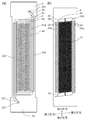
- FIG. 1A is a schematic side view of a color inkjet printer 1 (hereinafter sometimes simply referred to as a printer), which is a recording apparatus including a liquid ejection head 2 according to the first embodiment, and FIG. ) Is a schematic plan view.
- the printer 1 moves the printing paper P relative to the liquid ejection head 2 by conveying the printing paper P, which is a recording medium, from the paper feed roller 80 ⁇ / b> A to the collection roller 80 ⁇ / b> B.
- the control unit 88 controls the liquid ejection head 2 based on image and character data to eject liquid toward the printing paper P, land droplets on the printing paper P, and print on the printing paper P. Record such as.
- the liquid discharge head 2 is fixed to the printer 1 and the printer 1 is a so-called line printer, but is not limited to this.
- the printer 1 is a so-called line printer, but is not limited to this.
- a so-called serial printer in which the liquid ejection head 2 is moved by reciprocating in the direction intersecting the transport direction of the printing paper P, for example, in a substantially orthogonal direction, and the transport of the printing paper P alternately. I do not care.
- the printer 1 has a flat head mounting frame 70 (hereinafter sometimes simply referred to as a frame) fixed so as to be substantially parallel to the printing paper P.
- the frame 70 is provided with 20 holes (not shown), and the 20 liquid discharge heads 2 are mounted in the respective hole portions, and the portion of the liquid discharge head 2 that discharges the liquid is the printing paper P. It has come to face.
- the distance between the liquid ejection head 2 and the printing paper P is, for example, about 0.5 to 20 mm.
- the five liquid ejection heads 2 constitute one head group 72, and the printer 1 has four head groups 72.
- the liquid discharge head 2 has a long and narrow shape in the direction from the front to the back in FIG. 1A and in the vertical direction in FIG. This long direction is sometimes called the longitudinal direction.
- the three liquid ejection heads 2 are arranged along a direction that intersects the transport direction of the printing paper P, for example, a direction that is substantially orthogonal.
- the other two liquid discharge heads 2 are arranged one by one between the three liquid discharge heads 2 at positions shifted along the transport direction.
- the liquid discharge heads 2 are arranged so that the printable range of each liquid discharge head 2 is connected in the width direction of the print paper P (in the direction intersecting the conveyance direction of the print paper P) or the ends overlap. Thus, printing without gaps in the width direction of the printing paper P is possible.
- the four head groups 72 are arranged along the conveyance direction of the printing paper P.
- a liquid, for example, ink is supplied to each liquid ejection head 2 from a liquid tank (not shown).
- the liquid discharge heads 2 belonging to one head group 72 are supplied with the same color ink, and the four head groups 72 can print four color inks.
- the colors of ink ejected from each head group 72 are, for example, magenta (M), yellow (Y), cyan (C), and black (K).
- M magenta
- Y yellow
- C cyan
- K black
- a color image can be printed by printing such ink under the control of the control unit 88.
- the number of liquid discharge heads 2 mounted on the printer 1 may be one if it is a single color and the range that can be printed by one liquid discharge head 2 is printed.
- the number of liquid ejection heads 2 included in the head group 72 and the number of head groups 72 can be changed as appropriate according to the printing target and printing conditions. For example, the number of head groups 72 may be increased in order to perform multicolor printing. Also, if a plurality of head groups 72 that print in the same color are arranged and printed alternately in the transport direction, the transport speed can be increased even if the liquid ejection heads 2 having the same performance are used. Thereby, the printing area per time can be increased. Alternatively, a plurality of head groups 72 for printing in the same color may be prepared and arranged so as to be shifted in a direction crossing the transport direction, so that the resolution in the width direction of the print paper P may be increased.
- a liquid such as a coating agent may be printed for surface treatment of the printing paper P.
- the printer 1 performs printing on the printing paper P that is a recording medium.
- the printing paper P is wound around the paper feed roller 80A, passes between the two guide rollers 82A, passes through the lower side of the liquid ejection head 2 mounted on the frame 70, and thereafter It passes between the two conveying rollers 82B and is finally collected by the collecting roller 80B.
- the printing paper P is transported at a constant speed by rotating the transport roller 82 ⁇ / b> B and printed by the liquid ejection head 2.
- the collection roller 80B winds up the printing paper P sent out from the conveyance roller 82B.
- the paper feed roller 80A, the guide roller 82A, the transport roller 82B, and the collection roller 80B constitute a transport unit that transports the printing paper P to the liquid ejection head 2.
- the conveyance speed is, for example, 50 m / min.
- Each roller may be controlled by the controller 88 or may be manually operated by a person.
- the recording medium may be a roll-like cloth other than the printing paper P. Further, instead of directly transporting the printing paper P, the printer 1 may transport the transport belt directly and transport the recording medium placed on the transport belt. By doing so, sheets, cut cloth, wood, tiles and the like can be used as the recording medium. Furthermore, a wiring pattern of an electronic device may be printed by discharging a liquid containing conductive particles from the liquid discharge head 2. Still further, the chemical may be produced by discharging a predetermined amount of liquid chemical agent or liquid containing the chemical agent from the liquid discharge head 2 toward the reaction container or the like and reacting.
- FIG. 2A is a plan view showing a head main body 2a which is a main part of the liquid ejection head 2 shown in FIG.
- FIG. 2B is a plan view showing a state in which the second flow path member 6 is removed from the head main body 2a.
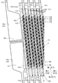
- FIG. 5 is a longitudinal sectional view taken along line VV in FIG.
- FIG. 6 is a partial longitudinal sectional view along the first common flow path 20 in the vicinity of the opening 20a of the first common flow path 20 of the head body 2a.
- FIG. 7 is a schematic plan view showing a state in which a part of the second plate 4k constituting the liquid ejection head 2 according to the first embodiment is viewed from the side opposite to the first plate 4m.
- FIGS. 2 to 4 the flow path and the like that should be drawn with a broken line below other objects are drawn with a solid line.
- FIG. 2A the flow paths in the first flow path member 4 are almost omitted, and only the arrangement of the individual electrodes 44 is shown.
- the liquid discharge head 2 may include a metal casing, a driver IC, a wiring board and the like in addition to the head main body 2a.
- the head body 2 a includes a first flow path member 4, a second flow path member 6 that supplies a liquid to the first flow path member 4, and a piezoelectric actuator substrate 40 having a pressurizing unit 50.
- the head body 2a has a flat plate shape that is long in one direction, and this direction is sometimes referred to as a longitudinal direction.
- the second flow path member 6 serves as a support member, and the head body 2 a is fixed to the frame 70 at both ends in the longitudinal direction of the second flow path member 6.
- the first flow path member 4 constituting the head body 2a has a flat plate shape and a thickness of about 0.5 to 2 mm.
- a number of pressurizing chambers 10 are arranged side by side in the plane direction.
- the discharge hole surface 4-2 which is the second main surface of the first flow path member 4 and on the opposite side of the pressurizing chamber surface 4-1, the discharge holes 8 for discharging the liquid are arranged in the plane direction. Many are arranged side by side. Each discharge hole 8 is connected to the pressurizing chamber 10. In the following description, it is assumed that the pressurizing chamber surface 4-1 is located above the discharge hole surface 4-2.
- first common flow paths 20 and a plurality of second common flow paths 24 are arranged so as to extend along the first direction. Moreover, the 1st common flow path 20 and the 2nd common flow path 24 are located in a line in the 2nd direction which is a direction which cross
- the second direction is the same direction as the longitudinal direction of the head body 2a.
- the pressurizing chambers 10 are arranged along both sides of the first common flow path 20 and constitute one pressurization chamber row 11A, one row on each side.
- the first common flow path 20 and the pressurizing chambers 10 arranged on both sides of the first common flow path 20 are connected via a first individual flow path 12.
- the pressurizing chambers 10 are arranged along both sides of the second common flow path 24, and the pressurizing chamber row 11A is constituted by one row on each side for a total of two rows.
- the second common flow path 24 and the pressurizing chambers 10 arranged on both sides thereof are connected via the second individual flow path 14.
- the first common channel 20 and the second common channel 24 may be collectively referred to as a common channel.
- the pressurizing chambers 10 are arranged side by side on a virtual line, the first common flow path 20 extends along one side of the virtual line, and along the other side of the virtual line.
- the second common flow path 24 extends.
- the virtual line in which the pressurizing chambers 10 are arranged is a straight line, but may be a curved line or a broken line.
- first common flow channel 20 and the second common flow channel 24 are outside the range where the pressurizing chambers are connected in the first direction, and the first connection flow channel 25A and the second connection flow channel 25B (both are connected to each other). In some cases, these are simply connected via a connection channel).
- a plurality of first individual channels 12 are connected to the first common channel 20 within a certain range in the first direction, and are connected to the plurality of pressurizing chambers 10 via the plurality of first individual channels 12. ing. This range is called an individual flow path connection region.
- the first common channel 20 is connected to the second common channel 24 adjacent in the second direction and one first connection channel 25A outside the individual channel connection region in the first direction. .
- connection channel 25B the second common channel 24 and one second adjacent to each other in the second direction outside the third direction (direction opposite to the first direction) of the individual channel connection region of the first common channel 20. It is connected via the connection channel 25B. That is, the first common flow path 20 is connected to the two first connection flow paths 25A on the outer side in the first direction of the individual flow path connection area, and the two on the outer side in the third direction of the individual flow path connection area.
- the second connection channel 25B is connected, and a total of four connection channels are connected.
- the liquid supplied to the second common flow path 24 flows into the pressurizing chambers 10 arranged along the second common flow path 24.
- a part of the liquid is discharged from the discharge hole 8, and the other part of the liquid is supplied to the first common flow path 20 located on the opposite side of the second common flow path 24 with respect to the pressurizing chamber 10. It flows in and is discharged out of the first flow path member 4. Further, a part of the liquid flows from the second common channel 24 into the first common channel 20 via the connection channel without passing through any of the pressurizing chambers 10.
- the channel resistance of the connection channel is larger than that of the first common channel 20 and the second common channel 24. For this reason, the main flow of the liquid is a flow through each pressurizing chamber 10. That is, the total flow rate of the liquid passing through the connection flow channel is less than half of the flow rate flowing through the portion having the highest flow rate in the first common flow channel 20. By doing in this way, the difference of the pressure added to the meniscus of each discharge hole 8 (it may only be called the pressure difference of a meniscus below) can be made small.
- the second common flow path 24 is disposed on both sides of the first common flow path 20, and the first common flow path 20 is disposed on both sides of the second common flow path 24. Accordingly, one first common flow path 20 and one second common flow path 24 are connected to one pressurization chamber row 11A, and another first pressurization chamber row 11A is connected to another first pressurization chamber row 11A. Compared with the case where one common flow path 20 and another second common flow path 24 are connected, the number of first common flow paths 20 and second common flow paths 24 can be halved. Since the number of first common channels 20 and second common channels 24 is small, the number of pressurizing chambers 10 is increased to increase the resolution, or the first common channel 20 and the second common channel 24 are thickened. Thus, the difference in ejection characteristics from the ejection holes 8 can be reduced, and the size of the head body 2a in the planar direction can be reduced.
- the pressure applied to the portion of the first individual flow path 12 on the first common flow path 20 side connected to the first common flow path 20 is affected by the pressure loss, so that the first individual flow path 12 is added to the first common flow path 20. Varies depending on the position where the two are connected (mainly the position in the first direction).
- the pressure applied to the portion of the second individual flow path 14 on the second common flow path 24 side connected to the second common flow path 24 is affected by the pressure loss, and the second individual flow path 14 is added to the second common flow path 24. Varies depending on the position where the two are connected (mainly the position in the first direction).
- each first The pressure difference due to the arrangement of the individual flow paths 12 and the second individual flow paths 14 is canceled out, and the pressure difference applied to the discharge holes 8 can be reduced. Note that both the opening 20a of the first common channel 20 and the opening 24a of the second common channel 24 open to the pressurizing chamber surface 4-1.
- the liquid meniscus is held in the discharge hole 8 in a state where the liquid is not discharged. Since the pressure of the liquid is a negative pressure (a state in which the liquid is about to be drawn into the first flow path member 4) in the discharge hole 8, the meniscus can be held in balance with the surface tension of the liquid. Since the surface tension of the liquid tries to reduce the surface area of the liquid, the meniscus can be held if the pressure is small even if it is a positive pressure. If the positive pressure increases, the liquid overflows, and if the negative pressure increases, the liquid is drawn into the first flow path member 4, and the liquid cannot be discharged. Therefore, it is necessary to prevent the meniscus pressure difference from becoming excessively large when the liquid flows from the second common channel 24 to the first common channel 20.
- the wall surface on the discharge hole surface 4-2 side of the first common flow path 20 is a first damper 28A.
- One surface of the first damper 28 ⁇ / b> A faces the first common flow path 20, and the other surface faces the damper chamber 29. Due to the presence of the damper chamber 29, the first damper 28A can be deformed, and the volume of the first common flow path 20 can be changed by the deformation.
- the liquid in the pressurizing chamber 10 is pressurized to discharge the liquid, part of the pressure is transmitted to the first common flow path 20 through the liquid.
- the liquid in the first common flow path 20 vibrates, and the vibration is transmitted to the original pressurizing chamber 10 and the other pressurizing chambers 10 to generate fluid crosstalk that fluctuates the discharge characteristics of the liquid.
- the first damper 28A When the first damper 28A exists, the first damper 28A vibrates due to the vibration of the liquid transmitted to the first common flow path 20, and the vibration of the liquid attenuates, so that the vibration of the liquid in the first common flow path 20 is attenuated. Since it becomes difficult to sustain, the influence of fluid crosstalk can be reduced. That is, it is possible to reduce the deterioration of discharge characteristics due to pressure transmission through the first common flow path 20.
- the first damper 28A also serves to stabilize the supply and discharge of the liquid.
- the wall surface on the pressure chamber surface 4-1 side of the second common flow path 24 is a second damper 28B.
- One surface of the second damper 28 ⁇ / b> B faces the second common flow path 24, and the other surface faces the damper chamber 29.
- the second damper 28B can reduce the influence of fluid crosstalk. That is, it is possible to reduce the deterioration of the discharge characteristics due to the pressure transmission through the second common flow path 24.
- the second damper 28B also serves to stabilize the supply and discharge of the liquid.
- the pressurizing chamber 10 is disposed so as to face the pressurizing chamber surface 4-1, and the pressurizing chamber main body 10a that receives the pressure from the pressurizing unit 50 and the discharge hole surface 4 from below the pressurizing chamber main body 10a.
- -2 is a hollow region including a descender 10b which is a partial flow path connected to the discharge hole 8 opened at -2.
- the pressurizing chamber body 10a has a right circular cylinder shape, and the planar shape is a circular shape. Since the planar shape is circular, the amount of displacement when the pressure unit 50 is deformed with the same force and the volume change of the pressure chamber 10 caused by the displacement can be increased.
- the descender 10b has a right circular cylinder shape whose diameter is smaller than that of the pressurizing chamber body 10a, and has a circular cross section. Further, the descender 10b is disposed at a position where it fits in the pressurizing chamber body 10a when viewed from the pressurizing chamber surface 4-1.
- the plurality of pressurizing chambers 10 are arranged in a staggered manner on the pressurizing chamber surface 4-1.
- the plurality of pressurizing chambers 10 constitute a plurality of pressurizing chamber rows 11A along the first direction.
- the pressurizing chambers 10 are arranged at substantially equal intervals.
- the pressurizing chambers 10 belonging to the adjacent pressurizing chamber row 11A are arranged in the first direction so as to be shifted by about half of the interval.
- the pressurizing chamber 10 belonging to a certain pressurizing chamber row 11A is in the first direction with respect to two consecutive pressurizing chambers 10 belonging to the pressurizing chamber row 11A located adjacent to the pressurizing chamber row 11A. It is located at the center.
- pressurizing chambers 10 belonging to every other pressurizing chamber row 11A are arranged along the second direction and constitute the pressurizing chamber row 11B.
- the first common flow path 20 is 51
- the second common flow path 24 is 50
- the pressurizing chamber row 11A is 100 rows.
- a dummy pressurizing chamber row 11D composed of only a dummy pressurizing chamber 10D described later is not included in the number of the pressurizing chamber rows 11A.
- the second common flow paths 24 that are directly connected to only the dummy pressurizing chamber 10D are not included in the number of the second common flow paths 24 described above.
- Each pressurizing chamber row 11A includes 16 pressurizing chambers 10.
- the pressurizing chamber row 11A located at the end in the second direction includes eight pressurizing chambers 10 and eight dummy pressurizing chambers 10D. As described above, since the pressurizing chambers 10 are arranged in a staggered manner, the number of pressurizing chamber rows 11B is 32.
- the plurality of pressurizing chambers 10 are arranged in a lattice shape along the first direction and the second direction on the discharge hole surface 4-2.
- the plurality of discharge holes 8 constitute a plurality of discharge hole arrays 9A along the first direction.
- the discharge hole row 9A and the pressurizing chamber row 11A are arranged at substantially the same position.
- the area center of gravity of the pressurizing chamber 10 and the discharge hole 8 connected to the pressurizing chamber 10 are shifted in the first direction.
- the shifted direction is the same direction, and in the adjacent pressurizing chamber row 11A, the shifted direction is the reverse direction.
- the discharge holes 8 connected to the pressurization chambers 10 belonging to the two pressurization chamber rows 11B constitute one discharge hole row 9B arranged along the second direction.
- the discharge hole column 9A has 100 columns, and the discharge hole row 9B has 16 rows.
- the area center of gravity of the pressurizing chamber body 10a and the discharge hole 8 connected from the pressurizing chamber body 10a are substantially displaced in the first direction.
- the descender 10b is disposed at a position shifted in the direction of the discharge hole 8 with respect to the pressurizing chamber body 10a.
- the side wall of the pressurizing chamber body 10a and the side wall of the descender 10b are disposed so as to be in contact with each other, thereby making it difficult for liquid to stay in the pressurizing chamber body 10a.
- the discharge hole 8 is arranged at the center of the descender 10b.
- the central portion is a region in a circle that is half the diameter of the descender 10b, centered on the center of gravity of the area of the descender 10b.
- the connecting portion between the first individual flow path 12 and the pressurizing chamber body 10a is disposed on the opposite side of the descender 10b with respect to the center of gravity of the area of the pressurizing chamber body 10a.
- the second individual flow path 14 is drawn in a planar direction from the surface on the discharge hole surface 4-2 side of the descender 10b and connected to the second common flow path 24.
- the drawing direction is the same as the direction in which the descender 10b is displaced with respect to the pressurizing chamber body 10a.
- the angle formed by the first direction and the second direction is deviated from a right angle. For this reason, the ejection holes 8 belonging to the ejection hole array 9A arranged along the first direction are displaced in the second direction by an angle shifted from the right angle. And since the discharge hole row
- discharge holes 8 belonging to one discharge hole row 9A are arranged in a straight line along the first direction, printing can be performed so as to fill the predetermined range as described above.
- a deviation between the direction perpendicular to the second direction and the transport direction that occurs when the liquid ejection head 2 is installed in the printer 1 has a great influence on the printing accuracy.
- the discharge holes 8 are replaced and arranged between the adjacent discharge hole rows 9A from the arrangement of the discharge holes 8 on the straight line described above.
- the arrangement of the discharge holes 8 is as follows.
- 32 discharge holes 8 are projected in the range of the virtual straight line R, and the discharge holes 8 are arranged at intervals of 360 dpi in the virtual straight line R. .
- the ejection holes 8 projected in the virtual straight line R belong to all (16) ejection holes 8 belonging to one ejection hole array 9A and to two ejection hole arrays 9A located on both sides of the ejection hole array 9A.
- Half of the discharge holes 8 (eight).
- the first common flow path 20 and the second common flow path 24 are straight in the range where the discharge holes 8 are arranged in a straight line, and are shifted in parallel between the discharge holes 8 where the straight lines are shifted.
- the flow path resistance is small. Further, since the portion that is shifted in parallel is arranged at a position that does not overlap with the pressurizing chamber 10, it is possible to reduce the variation in discharge characteristics for each pressurizing chamber 10.
- the pressurizing chamber row 11A of one row (that is, two rows in total) at both ends in the second direction includes the normal pressurizing chamber 10 and the dummy pressurizing chamber 10D (therefore, this pressurizing chamber 10D).
- the chamber row 11A may be referred to as a dummy pressurizing chamber row 11D).
- one row of dummy pressurizing chamber rows 11D in which only the dummy pressurizing chambers 10D are arranged (that is, two rows in total at both ends) is arranged.
- the flow paths, one at each end in the second direction (that is, two in total), have the same shape as the normal first common flow path 20, but directly with the pressurizing chamber 10 It is not connected and is connected only to the dummy pressurizing chamber 10D.
- the first flow path member 4 is located on the outer side in the second direction of the common flow path group including the first common flow path 20 and the second common flow path 24 and extends in the first direction. It has a path 30.
- the end channel 30 is aligned with the pressurizing chamber surface 4-1, and the opening 30c disposed further outside the opening 20a of the first common channel 20 aligned with the pressurizing chamber surface 4-1. This is a flow path that connects the opening 30 d that is disposed further outside the opening 24 a of the second common flow path 24.
- the head body 2a In order to stabilize the liquid ejection characteristics, the head body 2a is controlled to keep the temperature constant. Moreover, since the discharge and the circulation of the liquid become more stable when the viscosity of the liquid is lowered, the temperature is basically set to room temperature or higher. Therefore, basically, the head main body 2a is heated, but when the environmental temperature is high, the head main body 2a may be cooled.
- a heater is provided in the liquid discharge head 2 or the temperature of the liquid to be supplied is adjusted.
- heat dissipation from the end in the longitudinal direction (second direction) of the head main body 2a increases, and therefore, it is located at the center in the second direction.
- the temperature of the pressurizing chamber 10 located at both ends in the second direction tends to be lower than the temperature of the liquid in the pressurizing chamber 10.
- the end channel 30 is a channel that connects the first integrated channel 22 and the second integrated channel 26.
- the channel resistance of the end channel 30 is preferably smaller than the channel resistance of the first common channel 20 and the second common channel 24. By doing so, the amount of liquid flowing in the end channel 30 is increased, and the temperature drop inside the end channel 30 can be further reduced.
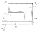
- the end channel 30 is provided with a wide portion 30a having a wider channel width than the common channel, and a damper is provided on the pressurizing chamber surface 4-1 side of the wide portion 30a. Yes.
- This damper has one surface facing the wide portion 30a and the other surface facing the damper chamber so that it can be deformed.
- the damping capacity of the damper is greatly influenced by the narrowest part where the deformable region is passed. Therefore, by providing the damper facing the wide portion 30a, a damper having a high damping capability can be obtained.
- the width of the wide portion 30a is preferably at least twice the width of the common channel, particularly at least three times. If the flow path resistance becomes too low by providing the wide part 30a, the narrowed part 30b may be provided to adjust the flow path resistance.
- the second flow path member 6 is joined to the pressurizing chamber surface 4-1 of the first flow path member 4.
- the second flow path member 6 includes a second integrated flow path 26 that supplies the liquid to the second common flow path 24 and a first integrated flow path 22 that recovers the liquid in the first common flow path 20. .
- the thickness of the second flow path member 6 is thicker than that of the first flow path member 4 and is about 5 to 30 mm.
- the first integrated channel 22 and the second integrated channel 26 may be collectively referred to as an integrated channel.
- the second flow path member 6 is joined in a region where the piezoelectric actuator substrate 40 of the pressure chamber surface 4-1 of the first flow path member 4 is not connected. More specifically, the piezoelectric actuator substrate 40 is joined so as to surround it. By doing in this way, it can reduce that a part of discharged liquid adheres to the piezoelectric actuator board
- the first flow path member 4 is fixed on the outer periphery, it is possible to reduce the occurrence of resonance or the like due to the vibration of the first flow path member 4 as the pressurizing unit 50 is driven.
- the through-hole 6c penetrates up and down at the center of the second flow path member 6.
- Wiring members such as FPC (Flexible ⁇ ⁇ PrintedFCircuit) for transmitting a drive signal for driving the piezoelectric actuator substrate 40 are passed through the through hole 6c.
- the 1st flow-path member 4 side of the through-hole 6c becomes the widening part 6ca where the width
- the wiring member extending from the piezoelectric actuator substrate 40 to both sides in the short direction is bent at the widened portion 6ca and goes upward, and passes through the through hole 6c.
- the convex part of the part which spreads in the wide part 6ca may damage a wiring member, it is good to make it R shape.
- the cross-sectional area of the first integrated flow path 22 is increased. Accordingly, a difference in pressure loss due to a difference in position where the first integrated flow path 22 and the first common flow path 20 are connected can be reduced.
- the flow resistance of the first integrated flow path 22 (more precisely, the flow resistance of the first integrated flow path 22 that is connected to the first common flow path 20) is It should be 1/100 or less.
- the cross-sectional area of the second integrated flow path 26 is increased. Accordingly, the difference in pressure loss due to the difference in the position where the second integrated channel 26 and the second common channel 24 are connected can be reduced.
- the flow resistance of the second integrated flow path 26 (more precisely, the flow resistance of the second integrated flow path 26 that is connected to the first integrated flow path 22) is that of the second common flow path 24. It should be 1/100 or less.
- the first integrated flow path 22 is located at one end of the second flow path member 6 in the short direction
- the second integrated flow path 26 is located at the other end of the second flow path member 6 in the short direction.
- both the 1st integrated flow path 22 and the 2nd integrated flow path 26 are arrange
- the cross-sectional areas of the first integrated flow path 22 and the second integrated flow path 26 can be increased (that is, the flow path resistance can be decreased), and the second flow path member 6 can
- the outer periphery can be fixed to increase the rigidity, and a through hole 6c through which the wiring member passes can be provided.
- the second flow path member 6 is configured by laminating plates 6a and 6b of the second flow path member.
- a first groove serving as a first integrated channel body 22a which is a portion of the first integrated channel 22 extending in the second direction and having a low channel resistance
- a second integrated channel 26 are provided on the upper surface of the plate 6b.
- a second groove serving as a second integrated flow path body 26a which is a portion having a low flow resistance extending in the second direction, is disposed.
- the lower side (the direction of the first flow path member 4) of the first groove serving as the first integrated flow path main body 22a is mostly blocked by the pressurization chamber surface 4-1, and a part thereof is a pressurization chamber. It is connected to the opening 20a of the first common flow path 20 opened on the surface 4-1.
- the lower side of the second groove serving as the second integrated flow path body 26a is mostly blocked by the pressurizing chamber surface 4-1, and a part thereof is opened on the pressurizing chamber surface 4-1. It is connected to the opening 24 a of the second common flow path 24.
- the plate 6 a is provided with an opening 22 c at the end in the second direction of the first integrated flow path 22.
- the plate 6a is provided with an opening 26c at the end of the second integrated channel 26 in the fourth direction opposite to the second direction.
- the liquid is supplied from the opening 26c of the second integrated flow path 26 and recovered from the opening 22c of the first integrated flow path 22.
- the present invention is not limited to this, and supply and recovery may be reversed.
- a damper may be provided in the first integrated flow path 22 and the second integrated flow path 26 so that the supply or discharge of the liquid is stabilized against fluctuations in the discharge amount of the liquid. Further, by providing a filter in the first integrated flow path 22 and the second integrated flow path 26, foreign substances and bubbles may be difficult to enter the first flow path member 4.
- a piezoelectric actuator substrate 40 including a pressurizing unit 50 is bonded to the pressurizing chamber surface 4-1 that is the upper surface of the first flow path member 4, and each pressurizing unit 50 is positioned on the pressurizing chamber 10.
- the piezoelectric actuator substrate 40 occupies a region having substantially the same shape as the pressurizing chamber group formed by the pressurizing chamber 10. Further, the opening of each pressurizing chamber 10 is closed by bonding the piezoelectric actuator substrate 40 to the pressurizing chamber surface 4-1 of the first flow path member 4.
- the piezoelectric actuator substrate 40 has a rectangular shape that is long in the same direction as the head body 2a.
- the piezoelectric actuator substrate 40 is connected to a signal transmission unit such as an FPC for supplying a signal to each pressing unit 50.
- the second flow path member 6 has a through hole 6c penetrating vertically at the center, and the signal transmission unit is electrically connected to the control unit 88 through the through hole 6c.
- the signal transmission unit has a shape extending in the short direction from one long side end of the piezoelectric actuator substrate 40 toward the other long side end, and the wiring disposed in the signal transmission unit extends along the short direction. If they are stretched and arranged in the longitudinal direction, the distance between the wirings can be easily taken.
- Individual electrodes 44 are respectively arranged at positions facing the pressurizing chambers 10 on the upper surface of the piezoelectric actuator substrate 40.
- the first flow path member 4 has a laminated structure in which a plurality of plates are laminated. Twelve plates from the plate 4a to the plate 4m are laminated in order from the pressurizing chamber surface 4-1 side of the first flow path member 4. Many holes and grooves are formed in these plates. These plates can be formed using, for example, various metals or resins. The holes and grooves can be formed by etching, for example. Moreover, adjacent plates can be joined using an adhesive etc., for example. Since the thickness of each plate is about 10 to 300 ⁇ m, the formation accuracy of the holes and grooves to be formed can be increased. Each plate is aligned and laminated so that these holes and grooves communicate with each other to form a flow path such as the first common flow path 20.
- the pressurizing chamber main body 10a is opened on the pressurizing chamber surface 4-1 of the flat plate-like first flow path member 4, and the piezoelectric actuator substrate 40 is joined thereto. Further, an opening 24 a for supplying a liquid to the second common flow path 24 and an opening 20 a for collecting the liquid from the first common flow path 20 are opened on the pressurizing chamber surface 4-1.
- a discharge hole 8 is opened in a discharge hole surface 4-2 on the opposite side of the pressurizing chamber surface 4-1, of the first flow path member 4.
- a plate may be further laminated on the pressurizing chamber surface 4-1, to close the opening of the pressurizing chamber main body 10a, and the piezoelectric actuator substrate 40 may be bonded thereon. By doing so, it is possible to reduce the possibility that the liquid to be discharged comes into contact with the piezoelectric actuator substrate 40, and the reliability can be further increased.
- the pressurizing chamber 10 includes a pressurizing chamber main body 10a facing the pressurizing unit 50 and a descender 10b having a smaller sectional area than the pressurizing chamber main body 10a.
- the pressurizing chamber main body 10a is formed in the plate 4a, and the descender 10b is overlapped with holes formed in the plates 4b to 4k, and is further blocked by the first plate 4m (parts other than the discharge holes 8). It is made up of.
- the first individual channel 12 is connected to the pressurizing chamber body 10 a, and the first individual channel 12 is connected to the first common channel 20.
- the first individual flow path 12 includes a circular hole that penetrates the plate 4b, a through groove that extends in the planar direction in the plate 4c, and a circular hole that penetrates the plate 4d.
- the first common flow path 20 is formed by overlapping holes formed in the plates 4f to 4i, and further closed by the plate 4e on the upper side and the plate 4j on the lower side.
- the descender 10 b is connected to the second individual flow path 14, and the second individual flow path 14 is connected to the second common flow path 24.
- the second individual flow path 14 is a through groove extending in the plane direction in the plate 4j.
- the second common flow path 24 is formed by overlapping holes formed in the plates 4f to 4i, and further closed by the plate 4e on the upper side and the plate 4j on the lower side.
- the liquid supplied to the second integrated flow path 26 enters the pressurizing chamber 10 through the second common flow path 24 and the second individual flow path 14 in order, and a part of the liquid flows. It is discharged from the discharge hole 8.
- the liquid that has not been discharged passes through the first individual flow path 12, enters the first common flow path 20, enters the first integrated flow path 22, and is discharged outside the head body 2.
- the piezoelectric actuator substrate 40 has a laminated structure composed of two piezoelectric ceramic layers 40a and 40b that are piezoelectric bodies. Each of these piezoelectric ceramic layers 40a and 40b has a thickness of about 20 ⁇ m. That is, the thickness from the upper surface of the piezoelectric ceramic layer 40a of the piezoelectric actuator substrate 40 to the lower surface of the piezoelectric ceramic layer 40b is about 40 ⁇ m.
- the thickness ratio between the piezoelectric ceramic layer 40a and the piezoelectric ceramic layer 40b is set to 3: 7 to 7: 3, preferably 4: 6 to 6: 4. Both of the piezoelectric ceramic layers 40 a and 40 b extend so as to straddle the plurality of pressure chambers 10.
- the piezoelectric ceramic layers 40a, 40b may, for example, strength with a dielectric, lead zirconate titanate (PZT), NaNbO 3 system, BaTiO 3 system, (BiNa) NbO 3 system, such as BiNaNb 5 O 15 system Made of ceramic material.
- PZT lead zirconate titanate
- NaNbO 3 system NaNbO 3 system
- BaTiO 3 system BaTiO 3 system
- BiNa NbO 3 system such as BiNaNb 5 O 15 system Made of ceramic material.
- the piezoelectric actuator substrate 40 has a common electrode 42 made of a metal material such as Ag—Pd and an individual electrode 44 made of a metal material such as Au.
- the common electrode 42 has a thickness of about 2 ⁇ m, and the individual electrode 44 has a thickness of about 1 ⁇ m.
- the individual electrodes 44 are disposed at positions facing the pressurizing chambers 10 on the upper surface of the piezoelectric actuator substrate 40, respectively.
- the individual electrode 44 has a planar shape slightly smaller than that of the pressurizing chamber main body 10a and has a shape substantially similar to the pressurizing chamber main body 10a, and an extraction electrode drawn from the individual electrode main body 44a. 44b.
- a connection electrode 46 is formed at a portion of one end of the extraction electrode 44 b that is extracted outside the region facing the pressurizing chamber 10.
- the connection electrode 46 is a conductive resin containing conductive particles such as silver particles, and is formed with a thickness of about 5 to 200 ⁇ m.
- the connection electrode 46 is electrically joined to an electrode provided in the signal transmission unit.
- a common electrode surface electrode (not shown) is formed on the upper surface of the piezoelectric actuator substrate 40.
- the common electrode surface electrode and the common electrode 42 are electrically connected through a through conductor (not shown) disposed in the piezoelectric ceramic layer 40a.
- a drive signal is supplied to the individual electrode 44 from the control unit 88 through the signal transmission unit.
- the drive signal is supplied in a constant cycle in synchronization with the conveyance speed of the printing paper P.
- the common electrode 42 is formed over substantially the entire surface in the region between the piezoelectric ceramic layer 40a and the piezoelectric ceramic layer 40b. That is, the common electrode 42 extends so as to cover all the pressurizing chambers 10 in the region facing the piezoelectric actuator substrate 40.
- the common electrode 42 is connected to the common electrode surface electrode formed on the piezoelectric ceramic layer 40a so as to avoid the electrode group composed of the individual electrodes 44 through via holes formed through the piezoelectric ceramic layer 40a. Are grounded and held at the ground potential.
- the common electrode surface electrode is directly or indirectly connected to the control unit 88 in the same manner as the plurality of individual electrodes 44.
- the portion sandwiched between the individual electrode 44 and the common electrode 42 of the piezoelectric ceramic layer 40a is polarized in the thickness direction, and is a unimorph-type displacement element that is displaced when a voltage is applied to the individual electrode 44. . More specifically, when an electric field is applied in the polarization direction to the piezoelectric ceramic layer 40a by setting the individual electrode 44 to a potential different from that of the common electrode 42, an active portion where the electric field is applied is distorted by the piezoelectric effect. Work as.
- a pressurizing unit 50 is configured.
- the pressurizing unit 50 is driven (displaced) by a drive signal supplied to the individual electrode 44 through a driver IC or the like under the control of the control unit 88.
- liquid can be ejected by various driving signals.
- strike driving method will be described.
- the individual electrode 44 is set to a potential higher than the common electrode 42 (hereinafter referred to as a high potential) in advance, and the individual electrode 44 is once set to the same potential as the common electrode 42 (hereinafter referred to as a low potential) every time there is a discharge request. Thereafter, the potential is set again at a predetermined timing. Thereby, at the timing when the individual electrode 44 becomes low potential, the piezoelectric ceramic layers 40a and 40b return to the original (flat) shape (begin), and the volume of the pressurizing chamber 10 is in the initial state (the potentials of both electrodes are different). Increase compared to the state). As a result, a negative pressure is applied to the liquid in the pressurizing chamber 10.
- the liquid in the pressurizing chamber 10 starts to vibrate with the natural vibration period. Specifically, first, the volume of the pressurizing chamber 10 begins to increase, and the negative pressure gradually decreases. Next, the volume of the pressurizing chamber 10 becomes maximum and the pressure becomes almost zero. Next, the volume of the pressurizing chamber 10 begins to decrease, and the pressure increases. Thereafter, the individual electrode 44 is set to a high potential at a timing at which the pressure becomes substantially maximum. Then, the first applied vibration overlaps with the next applied vibration, and a larger pressure is applied to the liquid. This pressure propagates through the descender and discharges the liquid from the discharge hole 8.
- a droplet can be ejected by supplying to the individual electrode 44 a pulse driving signal that is set to a low potential for a certain period of time with reference to a high potential.
- this pulse width is AL (Acoustic Length), which is half of the natural vibration period of the liquid in the pressurizing chamber 10, in principle, the liquid discharge speed and amount can be maximized.
- AL Acoustic Length
- the natural vibration period of the liquid in the pressurizing chamber 10 is greatly influenced by the physical properties of the liquid and the shape of the pressurizing chamber 10, but besides that, the physical properties of the piezoelectric actuator substrate 40 and the flow path connected to the pressurizing chamber 10 Also affected by the characteristics of.
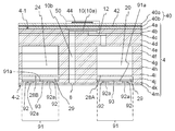
- FIG. 5 is a longitudinal sectional view taken along line VV in FIG.
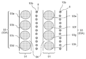
- FIG. 7 is a schematic plan view showing a state in which a part of the second plate 4k constituting the first flow path member 4 is viewed from the side opposite to the first plate 4m.
- the discharge hole surface 4-2 side of the first flow path member 4 is configured by arranging the first plate 4m, the second plate 4k, and the plate 4j in this order from the discharge hole surface 4-2 side.
- the surface of the plate 4j opposite to the discharge hole surface 4-2 is in contact with a plurality of common channels (the first common channel 20 and the second common channel 24) extending along the first direction, and the plate 4j On the opposite side (second plate 4k side) of the portion in contact with the common flow path (20, 24) in FIG.
- the recessed part is each formed also in the part which faces the recessed part formed in the plate 4j in the surface at the side of the plate 4j of the 2nd plate 4k.
- a plurality of common flow paths (20, 20) are formed by a space in which the plurality of recesses formed in the plate 4j and the plurality of recesses formed in the second plate 4k are arranged to face each other.
- the first damper 28A is configured by a wall that partitions the first common flow path 20 and the damper chamber 29, and the second damper 28B is configured by the wall that partitions the second common flow path 24 and the damper chamber 29.
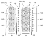
- the second plate 4k has a plurality of first portions 91 that are sandwiched between the damper chamber 29 and the first plate 4m. And the coating layer 93 is provided in the 1st surface 91a which is the surface on the opposite side to the 1st plate 4m in the 1st part 91 unevenly.
- the covering layer 93 can be configured using various known materials such as metals and resins.
- the cover layer 93 can be formed by bonding a separately formed plate-shaped cover layer 93 to the first surface 91a of the first portion 91 of the second plate 4k by a bonding member such as an adhesive.
- resin as a material which comprises the coating layer 93
- the coating layer 93 can be formed.
- the covering layer 93 may be a laminate of a plurality of layers, and the first plate 4m and the second plate 4k may be a composite of a plurality of members.
- the covering layer needs to be provided non-uniformly on the first surface 91a of the first portion 91.
- the state of “unevenly provided” is a state that is not a state of “the coating layer 93 is provided with the same thickness over the entire first surface 91a of the first portion 91”. That is, “the first surface 91 a of the first portion 91 has a portion where the covering layer 93 is provided and a portion where the covering layer 93 is not provided” or “the first portion 91 of the first portion 91 is first.
- the coating layer 93 is provided over the entire surface 91a, the thickness of the coating layer 93 varies depending on the location. "
- the first surface 91a of the first portion 91 has a portion where the covering layer 93 is provided and a portion where the covering layer 93 is not provided.
- the covering layer 93 is provided over the entire first surface 91a in 91, the thickness of the covering layer 93 varies depending on the location. In that case, it is desirable that the difference in thickness is large, and the thickness of the large thick part having a large thickness should be 1.5 times or more than the thickness of the small thick part having a small thickness. desirable. Note that it is desirable that the difference in thickness between the large thickness portion and the small thickness portion is larger, and it is more desirable that the thickness of the large thickness portion is twice or more the thickness of the small thickness portion. It is further desirable that the number is twice or more.
- the liquid ejection head 2 includes the plurality of pressurizing units 50 that pressurize the liquid and the first flow path member 4.
- the first flow path member 4 is disposed outside the plurality of discharge holes 8 for discharging liquid, the common flow path (20, 24) connected to the plurality of discharge holes 8, and the common flow path (20, 24).
- a damper chamber 29 configured by a wall that partitions the common flow path (20, 24) and the damper chamber 29 from each other.
- the first flow path member 4 is configured by laminating a plurality of flat plates (4a to 4m), and the plurality of plates (4a to 4m) is a first plate having a plurality of discharge holes 8. 4m and a second plate 4k adjacent to the first plate 4m.
- the second plate 4k has a first portion 91 sandwiched between the first plate 4m and the damper chamber 29, and the coating layer 93 is provided unevenly on the first surface 91a of the first portion 91. .
- the liquid discharge head 2 of this embodiment having such a configuration can reduce the occurrence of large vibrations on the surface (discharge hole surface 4-2) where the discharge holes 8 are formed, as described below. it can.
- the coating layer 93 is provided unevenly on the first surface 91a of the first portion 91.
- the planar shape of the first region 93A where the covering layer 93 is formed is desirably a shape having low symmetry. That is, the planar shape of the first region 93A is desirably a shape that does not have symmetry such as line symmetry or rotational symmetry.
- the plurality of ejection holes 8 are arranged to form a plurality of rows, and the first portions 91 are located between the rows and in a direction along the rows. It has a long shape in a certain first direction.
- the covering layer 93 has a shape in which wide portions and narrow portions alternately exist along the first direction.
- the widths of the adjacent narrow portions are different from each other. That is, as shown in FIG. 7, when the width of each narrow portion is W1, W2, W3, W4, W5, and W6, W1 and W2 are different, W2 and W3 are different, and W4 And W5 are different, and it is desirable that W5 and W6 be different. Thereby, since the structural symmetry can be further lowered, the effect of reducing a large vibration at a specific frequency can be further enhanced.
- the linear expansion coefficient of the material constituting the first plate 4m and the linear expansion coefficient of the material constituting the covering layer 93 are set larger than the linear expansion coefficient of the material constituting the second plate 4k. Also good. Thereby, when the adhesive which joins the 1st plate 4m and the 2nd plate 4k is hardened by heating and it returns to normal temperature, the 1st plate 4m and the coating layer 93 contract more largely than the 2nd plate 4k. . Accordingly, the portion adjacent to the damper chamber 29 on the discharge hole surface 4-2 can be deformed so as to be slightly recessed, and the amount of depression in the recessed portion can be prevented from becoming excessively large.
- the thickness of the covering layer 93 is made smaller than the thickness of the first plate 4m, it is possible to easily prevent the portion adjacent to the damper chamber 29 on the discharge hole surface 4-2 from being deformed so as to be convex. Can do.
- the non-formation region of the covering layer 93 exists in the peripheral portion of the first portion 91 so that the covering layer 93 is unevenly distributed in the central portion of the first portion 91. Good. As a result, it is possible to enhance the effect of preventing the amount of depression in the portion adjacent to the damper chamber 29 on the discharge hole surface 4-2 from becoming excessively large.
- the condition of the linear expansion coefficient is set. It can be appropriately selected from a variety of known materials so as to satisfy. For example, as an example, stainless steel is selected as the material of the plates 4a to 4k including the second plate 4k, nickel is selected as the material of the first plate 4m, and epoxy resin is selected as the material of the covering layer 93. can do.
- a stainless alloy is selected as the material of the plates 4a to 4k including the second plate 4k
- a polyimide resin is selected as the material of the first plate 4m
- an epoxy resin is used as the material of the covering layer 93.
- a metal having a small linear expansion coefficient such as carbon steel can be selected, and as a material of the first plate 4m, for example, tin is used.
- a metal having a large linear expansion coefficient can be selected, and a metal having a large linear expansion coefficient and a low melting point such as tin or lead can be selected as the material of the covering layer 93.
- the paste is applied to the first surface 91a in the first portion 91.
- the coating layer 93 is formed by disposing a metal in the form of a powder, powder, or particles, melting the metal by heating when the adhesive for bonding the first plate 4m and the second plate 4k is cured, and then returning the metal to room temperature. Can be formed.
- the plate-like covering layer 93 is attached to the first surface 91a of the first portion 91 via an adhesive
- the adhesive for bonding the first plate 4m and the second plate 4k is heated and cured, the coating layer 93 can be formed by simultaneously curing the adhesive.
- FIG. 8 is a schematic plan view showing a state similar to FIG. 7 in the liquid ejection head of the second embodiment.
- differences from the above-described first embodiment will be described, and the same components are denoted by the same reference numerals, and redundant description will be omitted.
- the covering layer 93 is divided into a plurality of regions. That is, as shown in FIG. 8, the first region 93A provided with the covering layer 93 is divided into a plurality of regions (93a, 93b, 93c, 93d, 93e, 93f, 93g, 93h). Even with such a structure, it is possible to reduce the vibration of the portion sandwiched between the discharge hole surface 4-2 and the damper chamber 29 at a specific frequency.
- the area of the region 93a and the area of the region 93b are different, the area of the region 93b and the area of the region 93c are different, the area of the region 93c and the area of the region 93d are different, and the region 93e
- the area of the region 93f is different from the area of the region 93f
- the area of the region 93f is different from the area of the region 93g
- the area of the region 93g is different from the area of the region 93h.
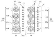
- FIG. 9 is a schematic plan view showing a state similar to FIG. 7 in the liquid ejection head of the third embodiment.
- FIG. 10 is a schematic partial cross-sectional view showing the same state as that of FIG. 5 in the liquid ejection head of the third embodiment.
- differences from the above-described first embodiment will be described, and the same components are denoted by the same reference numerals, and redundant description will be omitted.
- a plurality of through holes 92 are provided in the first portion 91 of the second plate 4k, and a filler 92a is provided inside the plurality of through holes 92.
- the material constituting 92a is made different from the material constituting the second plate 4k.
- the material constituting the filler 92a various known materials such as metal, resin, and glass can be used.
- the filler 92a can be formed by filling the through-hole 92 with an uncured resin to be the filler 92a and heating and curing the resin. it can.
- the thickness for applying the adhesive for joining the first plate 4m and the second plate 4k is made thicker than usual, and the pressure applied after the first plate 4m and the second plate 4k are bonded is adjusted.
- the low-viscosity adhesive may be filled in the through-hole 92, and the filler 92a may be configured by curing the adhesive.
- the thickness of applying the adhesive that joins the first plate 4m and the second plate 4k is set to be 1/2 or more of the thickness of the second plate 4k, and the first plate 4m and the second plate 4k.
- the adhesive with reduced viscosity is filled inside the through-hole 92 and oozes out to the surface of the second plate 4k on the plate 4j side, which is cured.
- the covering layer 93 may be configured together with the filler 92a.
- the plurality of through holes 92 are non-uniformly arranged in the first portion 91.
- the structural symmetry can be lowered, so that a large vibration caused by a resonance phenomenon occurs in a portion sandwiched between the discharge hole surface 4-2 and the damper chamber 29, and the discharge characteristics deteriorate. Can be reduced.
- the through-holes 92 are unevenly arranged means that the existence density of the through-holes 92 in the first portion 91 is not constant, that is, a portion where the through-holes 92 are densely arranged This means that there are portions where the holes 92 are sparsely arranged.
- the plurality of discharge holes 8 are arranged in a plurality of rows.
- the first portions 91 are located between the rows and have a shape that is long in the first direction, which is the direction along the rows.
- a plurality of through-hole groups each having a plurality of through-holes 92 arranged close to each other are arranged at intervals along the first direction. With such a configuration, it is possible to reduce a large vibration caused by the resonance phenomenon over the entire first portion 91 that is long in the first direction.
- one through hole group is configured by the four through holes 92, and the through hole group configured in this way is the length of the first portion 91.
- a plurality of elements are arranged at intervals along the first direction.
- the linear expansion coefficient of the material forming the first plate 4m is larger than the linear expansion coefficient of the material forming the second plate 4k, and the linear expansion coefficient of the material forming the filler 92a is higher.
- the linear expansion coefficient of the material constituting the second plate 4k may be larger.
- the specific material constituting the filler 92a can be appropriately selected from various known materials so as to satisfy the linear expansion coefficient.
- the material of the filler 92a is a metal such as nickel, tin, lead, polyimide, epoxy resin, etc. These resins can be suitably used.
- the through-hole 92 has a powdery or granular metal.
- the filler 92a is formed by melting the powdered or granular metal by heating when curing the adhesive for joining the first plate 4m and the second plate 4k, and then returning to normal temperature. can do.
- the part located in the center of the through-hole 92 is planarly dented to the 1st plate 4m side when planarly viewed. It is desirable to do. As a result, a stress is generated in the second plate 4k along the surface of the filler 92a opposite to the first plate 4m, and the stress is generated in the second plate 4k. The effect of preventing the amount of dents in adjacent portions from becoming excessively large can be enhanced.
- FIG. 11 is a schematic plan view showing a state similar to FIG. 9 in the liquid ejection head of the fourth embodiment.
- differences from the above-described third embodiment will be described, and the same components are denoted by the same reference numerals, and redundant description will be omitted.
- the covering layer 93 is divided into a plurality of regions. That is, as shown in FIG. 11, the first region 93A provided with the covering layer 93 is divided into a plurality of regions (93a, 93b, 93c, 93d, 93e, 93f, 93g, 93h).
- the liquid discharge head of this embodiment having such a structure also has the coating layer 93 and the through-holes 92 that are provided non-uniformly, as in the third embodiment described above. 2 and the damper chamber 29 can be reduced from greatly vibrating at a specific frequency.
- the area 93a and the area 93b are different, the area 93b and the area 93c are different, the area 93c and the area 93d are different, and the area 93e.
- the area of the region 93f is different from the area of the region 93f, the area of the region 93f is different from the area of the region 93g, and the area of the region 93g is different from the area of the region 93h.
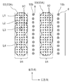
- FIG. 12 is a schematic plan view showing a state similar to FIG. 9 in the liquid ejection head of the fifth embodiment.
- differences from the above-described third embodiment will be described, and the same components are denoted by the same reference numerals, and redundant description will be omitted.
- the plurality of through holes 92 do not form a through hole group, and the through holes 92 larger than the through holes 92 in the third embodiment are arranged along the first direction. That is, assuming that two directions orthogonal to each other are a B direction (first direction) and a C direction, the dimension of the first portion 91 in the B direction is the dimension of the first portion 91 in the C direction (indicated by L2 in FIG. 12).
- the plurality of through holes 92 are arranged along the B direction. Even with such a structure, it is possible to reduce the vibration of the portion sandwiched between the discharge hole surface 4-2 and the damper chamber 29 at a specific frequency.
- the through hole 92 makes the rigidity and mass distribution in the composite of the first portion 91 and the covering layer 93 non-uniform, thereby reducing the structural symmetry of the composite.
- the resonance frequency can be dispersed by solving the degeneration of the resonance mode, the complex of the first portion 91 and the covering layer 93 can be reduced from greatly vibrating at a specific frequency.
- the through hole 92 is preferably large to some extent, and the asymmetry in the shape of the through hole 92 is preferably large.
- the dimension of the first portion 91 in the C direction (the length of the portion indicated by L2 in FIG. 12) is D
- the dimension of the through hole 92 in the C direction is the length of the portion indicated by L1 in FIG. 12.
- Is E it is better to satisfy E / D ⁇ 0.22, and it is even better to satisfy E / D ⁇ 0.25 or E / D ⁇ 0.30.
- the dimension in the B direction of the through hole 92 (the length of the portion indicated by L3 in FIG. 12) is F, and the interval between the adjacent through holes 92 in the B direction (the portion indicated by L4 in FIG. 12).
- G G
- F / G ⁇ 0.79 it is preferable to satisfy F / G ⁇ 0.88 or F / G ⁇ 1.06.
- the dimension of the through hole 92 in the B direction (the length of the portion indicated by L3 in FIG. 12) is H
- the dimension of the through hole 92 in the C direction is the length of the portion indicated by L1 in FIG. 12.
- each through hole 92 has a shape in which a circle is extended in the B direction, and a plurality of through holes 92 having the same shape and size are formed in the first portion 91.
- the shapes and sizes of the plurality of through-holes 92 may be different from each other, the plurality of through-holes 92 may be arranged to be shifted from the center in the B direction in the first portion 91, and the interval between the adjacent through-holes 92 is set. It may vary depending on the location. Further, the desirable relationship between the dimensions related to the through-holes 92 described above does not necessarily require that all the through-holes 92 satisfy the relationship.
- Partial flow path DESCRIPTION OF SYMBOLS 10D ... Dummy pressurization chamber 11A ... Pressurization chamber row
Abstract
A liquid discharge head has a first flow path member 4 and a plurality of pressurizing units 50. The first flow path member 4 has a plurality of discharge holes 8, common flow paths (20, 24), damper chambers 29, and dampers (28A, 28B). The first flow path member 4 is composed of a plurality of plates (4a-4m) including a first plate 4m having the plurality of discharge holes 8 and an adjacent second plate 4k. The second plate 4k has first parts 91 which are sandwiched by the damper chambers 29 and the first plate 4m, and covering layers 93 are provided non-uniformly to first surfaces 91a in the first parts 91.
Description
本開示は、液体吐出ヘッドおよびそれを用いた記録装置に関する。
The present disclosure relates to a liquid discharge head and a recording apparatus using the same.
従来、印刷用ヘッドとして、例えば、液体を記録媒体上に吐出することによって印刷を行なう液体吐出ヘッドが知られている。このような液体吐出ヘッドとしては、例えば、液体を吐出する複数の吐出孔と、複数の吐出孔の各々に対応して設けられて吐出孔から液体が吐出されるように液体を加圧する複数の加圧室と、複数の加圧室に液体を供給する共通流路と、を備えたものが知られている(例えば、特許文献1を参照。)。
Conventionally, as a print head, for example, a liquid discharge head that performs printing by discharging a liquid onto a recording medium is known. As such a liquid ejection head, for example, a plurality of ejection holes for ejecting liquid and a plurality of ejection holes provided corresponding to each of the plurality of ejection holes to pressurize the liquid so that the liquid is ejected from the ejection holes. What is provided with the pressurization chamber and the common flow path which supplies a liquid to a some pressurization chamber is known (for example, refer patent document 1).
本開示の液体吐出ヘッドは、流路部材と、複数の加圧部と、を有している。前記流路部材は、複数の吐出孔と、共通流路と、ダンパー室と、ダンパーと、を有している。前記複数の吐出孔は、液体を吐出する孔である。前記共通流路は、前記複数の吐出孔と繋がっている。前記ダンパー室は、前記共通流路の外側に配置された空間で構成されている。前記ダンパーは、前記共通流路と前記ダンパー室とを仕切る壁によって構成されている。前記複数の加圧部は、前記液体を加圧する。前記流路部材は、積層された複数の平板状のプレートで構成されている。該複数のプレートは、前記複数の吐出孔を有する第1プレートと、該第1プレートに隣り合う第2プレートと、を有している。該第2プレートは、前記第1プレートと前記ダンパー室とで挟まれた第1部分を有している。該第1部分は、前記第1プレートと反対側に位置する第1表面を有している。前記液体吐出ヘッドは、前記第1部分における前記第1表面に不均一に設けられた被覆層を有している。
The liquid discharge head according to the present disclosure includes a flow path member and a plurality of pressure units. The flow path member has a plurality of discharge holes, a common flow path, a damper chamber, and a damper. The plurality of discharge holes are holes for discharging a liquid. The common channel is connected to the plurality of discharge holes. The damper chamber is configured by a space arranged outside the common flow path. The damper is constituted by a wall that partitions the common flow path and the damper chamber. The plurality of pressurizing units pressurize the liquid. The flow path member is composed of a plurality of stacked flat plates. The plurality of plates include a first plate having the plurality of discharge holes and a second plate adjacent to the first plate. The second plate has a first portion sandwiched between the first plate and the damper chamber. The first portion has a first surface located on the opposite side of the first plate. The liquid discharge head includes a coating layer provided nonuniformly on the first surface of the first portion.
発明者らは、特許文献1に記載されているような液体吐出ヘッドが駆動しているときに、吐出孔が形成された表面に、振幅が2~3μm程度の微小な振動が発生することを確認した。このような振動が液体の吐出特性を悪化させている可能性があり、また、このような振動が大きくなると、液体の吐出特性を更に悪化させることが推測される。
The inventors have found that when the liquid discharge head as described in Patent Document 1 is driven, minute vibrations having an amplitude of about 2 to 3 μm are generated on the surface where the discharge holes are formed. confirmed. There is a possibility that such vibrations are deteriorating the liquid ejection characteristics, and when such vibrations are increased, it is presumed that the liquid ejection characteristics are further deteriorated.
本開示の液体吐出ヘッドは、吐出孔が形成された表面において大きな振動が発生するのを低減することができる。以下、本開示の液体吐出ヘッドおよびそれを用いた記録装置について、詳細に説明する。
The liquid discharge head of the present disclosure can reduce the occurrence of large vibrations on the surface where the discharge holes are formed. Hereinafter, the liquid ejection head of the present disclosure and the recording apparatus using the same will be described in detail.
(第1実施形態)
図1(a)は、第1実施形態に係る液体吐出ヘッド2を含む記録装置であるカラーインクジェットプリンタ1(以下で単にプリンタと言うことがある)の概略の側面図であり、図1(b)は、概略の平面図である。プリンタ1は、記録媒体である印刷用紙Pを給紙ローラ80Aから回収ローラ80Bへと搬送することにより、印刷用紙Pを液体吐出ヘッド2に対して相対的に移動させる。制御部88は、画像や文字のデータに基づいて、液体吐出ヘッド2を制御して、印刷用紙Pに向けて液体を吐出させ、印刷用紙Pに液滴を着弾させて、印刷用紙Pに印刷などの記録を行なう。 (First embodiment)
FIG. 1A is a schematic side view of a color inkjet printer 1 (hereinafter sometimes simply referred to as a printer), which is a recording apparatus including aliquid ejection head 2 according to the first embodiment, and FIG. ) Is a schematic plan view. The printer 1 moves the printing paper P relative to the liquid ejection head 2 by conveying the printing paper P, which is a recording medium, from the paper feed roller 80 </ b> A to the collection roller 80 </ b> B. The control unit 88 controls the liquid ejection head 2 based on image and character data to eject liquid toward the printing paper P, land droplets on the printing paper P, and print on the printing paper P. Record such as.
図1(a)は、第1実施形態に係る液体吐出ヘッド2を含む記録装置であるカラーインクジェットプリンタ1(以下で単にプリンタと言うことがある)の概略の側面図であり、図1(b)は、概略の平面図である。プリンタ1は、記録媒体である印刷用紙Pを給紙ローラ80Aから回収ローラ80Bへと搬送することにより、印刷用紙Pを液体吐出ヘッド2に対して相対的に移動させる。制御部88は、画像や文字のデータに基づいて、液体吐出ヘッド2を制御して、印刷用紙Pに向けて液体を吐出させ、印刷用紙Pに液滴を着弾させて、印刷用紙Pに印刷などの記録を行なう。 (First embodiment)
FIG. 1A is a schematic side view of a color inkjet printer 1 (hereinafter sometimes simply referred to as a printer), which is a recording apparatus including a
本実施形態では、液体吐出ヘッド2はプリンタ1に対して固定されており、プリンタ1はいわゆるラインプリンタとなっているが、これに限定されるものではない。例えば、液体吐出ヘッド2を、印刷用紙Pの搬送方向に交差する方向、例えば、ほぼ直交する方向に往復させるなどして移動させる動作と、印刷用紙Pの搬送を交互に行なう、いわゆるシリアルプリンタでも構わない。
In this embodiment, the liquid discharge head 2 is fixed to the printer 1 and the printer 1 is a so-called line printer, but is not limited to this. For example, even a so-called serial printer in which the liquid ejection head 2 is moved by reciprocating in the direction intersecting the transport direction of the printing paper P, for example, in a substantially orthogonal direction, and the transport of the printing paper P alternately. I do not care.
プリンタ1には、印刷用紙Pとほぼ平行となるように平板状のヘッド搭載フレーム70(以下で単にフレームと言うことがある)が固定されている。フレーム70には図示しない20個の孔が設けられており、20個の液体吐出ヘッド2がそれぞれの孔の部分に搭載されていて、液体吐出ヘッド2の、液体を吐出する部位が印刷用紙Pに面するようになっている。液体吐出ヘッド2と印刷用紙Pとの間の距離は、例えば0.5~20mm程度とされる。5つの液体吐出ヘッド2は、1つのヘッド群72を構成しており、プリンタ1は、4つのヘッド群72を有している。
The printer 1 has a flat head mounting frame 70 (hereinafter sometimes simply referred to as a frame) fixed so as to be substantially parallel to the printing paper P. The frame 70 is provided with 20 holes (not shown), and the 20 liquid discharge heads 2 are mounted in the respective hole portions, and the portion of the liquid discharge head 2 that discharges the liquid is the printing paper P. It has come to face. The distance between the liquid ejection head 2 and the printing paper P is, for example, about 0.5 to 20 mm. The five liquid ejection heads 2 constitute one head group 72, and the printer 1 has four head groups 72.
液体吐出ヘッド2は、図1(a)の手前から奥へ向かう方向、図1(b)の上下方向に細長い長尺形状を有している。この長い方向を長手方向と呼ぶことがある。1つのヘッド群72内において、3つの液体吐出ヘッド2は、印刷用紙Pの搬送方向に交差する方向、例えば、ほぼ直交する方向に沿って並んでいる。他の2つの液体吐出ヘッド2は、搬送方向に沿ってずれた位置で、3つの液体吐出ヘッド2の間にそれぞれ一つずつ並んでいる。液体吐出ヘッド2は、各液体吐出ヘッド2で印刷可能な範囲が、印刷用紙Pの幅方向に(印刷用紙Pの搬送方向に交差する方向に)繋がるように、あるいは端が重複するように配置されており、印刷用紙Pの幅方向に隙間のない印刷が可能になっている。
The liquid discharge head 2 has a long and narrow shape in the direction from the front to the back in FIG. 1A and in the vertical direction in FIG. This long direction is sometimes called the longitudinal direction. In one head group 72, the three liquid ejection heads 2 are arranged along a direction that intersects the transport direction of the printing paper P, for example, a direction that is substantially orthogonal. The other two liquid discharge heads 2 are arranged one by one between the three liquid discharge heads 2 at positions shifted along the transport direction. The liquid discharge heads 2 are arranged so that the printable range of each liquid discharge head 2 is connected in the width direction of the print paper P (in the direction intersecting the conveyance direction of the print paper P) or the ends overlap. Thus, printing without gaps in the width direction of the printing paper P is possible.
4つのヘッド群72は、印刷用紙Pの搬送方向に沿って配置されている。各液体吐出ヘッド2には、図示しない液体タンクから液体、例えば、インクが供給される。1つのヘッド群72に属する液体吐出ヘッド2には、同じ色のインクが供給されるようになっており、4つのヘッド群72で4色のインクが印刷できる。各ヘッド群72から吐出されるインクの色は、例えば、マゼンタ(M)、イエロー(Y)、シアン(C)およびブラック(K)である。このようなインクを、制御部88で制御して印刷すれば、カラー画像が印刷できる。
The four head groups 72 are arranged along the conveyance direction of the printing paper P. A liquid, for example, ink is supplied to each liquid ejection head 2 from a liquid tank (not shown). The liquid discharge heads 2 belonging to one head group 72 are supplied with the same color ink, and the four head groups 72 can print four color inks. The colors of ink ejected from each head group 72 are, for example, magenta (M), yellow (Y), cyan (C), and black (K). A color image can be printed by printing such ink under the control of the control unit 88.
プリンタ1に搭載されている液体吐出ヘッド2の個数は、単色で、1つの液体吐出ヘッド2で印刷可能な範囲を印刷するのなら1つでもよい。ヘッド群72に含まれる液体吐出ヘッド2の個数や、ヘッド群72の個数は、印刷する対象や印刷条件により適宜変更できる。例えば、さらに多色の印刷をするためにヘッド群72の個数を増やしてもよい。また、同色で印刷するヘッド群72を複数配置して、搬送方向に交互に印刷すれば、同じ性能の液体吐出ヘッド2を使用しても搬送速度を速くできる。これにより、時間当たりの印刷面積を大きくすることができる。また、同色で印刷するヘッド群72を複数準備して、搬送方向と交差する方向にずらして配置して、印刷用紙Pの幅方向の解像度を高くしてもよい。
The number of liquid discharge heads 2 mounted on the printer 1 may be one if it is a single color and the range that can be printed by one liquid discharge head 2 is printed. The number of liquid ejection heads 2 included in the head group 72 and the number of head groups 72 can be changed as appropriate according to the printing target and printing conditions. For example, the number of head groups 72 may be increased in order to perform multicolor printing. Also, if a plurality of head groups 72 that print in the same color are arranged and printed alternately in the transport direction, the transport speed can be increased even if the liquid ejection heads 2 having the same performance are used. Thereby, the printing area per time can be increased. Alternatively, a plurality of head groups 72 for printing in the same color may be prepared and arranged so as to be shifted in a direction crossing the transport direction, so that the resolution in the width direction of the print paper P may be increased.
さらに、色の付いたインクを印刷する以外に、印刷用紙Pの表面処理をするために、コーティング剤などの液体を印刷してもよい。
Furthermore, in addition to printing colored inks, a liquid such as a coating agent may be printed for surface treatment of the printing paper P.
プリンタ1は、記録媒体である印刷用紙Pに印刷を行なう。印刷用紙Pは、給紙ローラ80Aに巻き取られた状態になっており、2つのガイドローラ82Aの間を通った後、フレーム70に搭載されている液体吐出ヘッド2の下側を通り、その後2つの搬送ローラ82Bの間を通り、最終的に回収ローラ80Bに回収される。印刷する際には、搬送ローラ82Bを回転させることで印刷用紙Pは、一定速度で搬送され、液体吐出ヘッド2によって印刷される。回収ローラ80Bは、搬送ローラ82Bから送り出された印刷用紙Pを巻き取る。このように、給紙ローラ80A、ガイドローラ82A、搬送ローラ82B、回収ローラ80Bによって、印刷用紙Pを液体吐出ヘッド2に対して搬送する搬送部が構成されている。搬送速度は、例えば、50m/分とされる。各ローラは、制御部88によって制御されてもよいし、人によって手動で操作されてもよい。
The printer 1 performs printing on the printing paper P that is a recording medium. The printing paper P is wound around the paper feed roller 80A, passes between the two guide rollers 82A, passes through the lower side of the liquid ejection head 2 mounted on the frame 70, and thereafter It passes between the two conveying rollers 82B and is finally collected by the collecting roller 80B. When printing, the printing paper P is transported at a constant speed by rotating the transport roller 82 </ b> B and printed by the liquid ejection head 2. The collection roller 80B winds up the printing paper P sent out from the conveyance roller 82B. As described above, the paper feed roller 80A, the guide roller 82A, the transport roller 82B, and the collection roller 80B constitute a transport unit that transports the printing paper P to the liquid ejection head 2. The conveyance speed is, for example, 50 m / min. Each roller may be controlled by the controller 88 or may be manually operated by a person.
記録媒体は、印刷用紙P以外に、ロール状の布などでもよい。また、プリンタ1は、印刷用紙Pを直接搬送する代わりに、搬送ベルトを直接搬送して、記録媒体を搬送ベルトに置いて搬送してもよい。そのようにすれば、枚葉紙や裁断された布、木材、タイルなどを記録媒体にできる。さらに、液体吐出ヘッド2から導電性の粒子を含む液体を吐出するようにして、電子機器の配線パターンなどを印刷してもよい。またさらに、液体吐出ヘッド2から反応容器などに向けて所定量の液体の化学薬剤や化学薬剤を含んだ液体を吐出させて、反応させるなどして、化学薬品を作製してもよい。
The recording medium may be a roll-like cloth other than the printing paper P. Further, instead of directly transporting the printing paper P, the printer 1 may transport the transport belt directly and transport the recording medium placed on the transport belt. By doing so, sheets, cut cloth, wood, tiles and the like can be used as the recording medium. Furthermore, a wiring pattern of an electronic device may be printed by discharging a liquid containing conductive particles from the liquid discharge head 2. Still further, the chemical may be produced by discharging a predetermined amount of liquid chemical agent or liquid containing the chemical agent from the liquid discharge head 2 toward the reaction container or the like and reacting.
次に、第1実施形態の液体吐出ヘッド2について説明する。図2(a)は、図1に示された液体吐出ヘッド2の要部であるヘッド本体2aを示す平面図である。図2(b)は、ヘッド本体2aから第2流路部材6を除いた状態の平面図である。図3および図4は、図2(b)の拡大平面図である。図5は、図4のV-V線に沿った縦断面図である。図6は、ヘッド本体2aの第1共通流路20の開口20a付近における、第1共通流路20に沿った部分縦断面図である。図7は、第1実施形態に係る液体吐出ヘッド2を構成する第2プレート4kの一部分を、第1プレート4mと反対側から見た状態を示す模式的な平面図である。
Next, the liquid discharge head 2 of the first embodiment will be described. FIG. 2A is a plan view showing a head main body 2a which is a main part of the liquid ejection head 2 shown in FIG. FIG. 2B is a plan view showing a state in which the second flow path member 6 is removed from the head main body 2a. 3 and 4 are enlarged plan views of FIG. 2 (b). FIG. 5 is a longitudinal sectional view taken along line VV in FIG. FIG. 6 is a partial longitudinal sectional view along the first common flow path 20 in the vicinity of the opening 20a of the first common flow path 20 of the head body 2a. FIG. 7 is a schematic plan view showing a state in which a part of the second plate 4k constituting the liquid ejection head 2 according to the first embodiment is viewed from the side opposite to the first plate 4m.
各図は、図面を分かり易くするために次のように描いている。図2~4では、他のものの下方にあって破線で描くべき流路などを実線で描いている。図2(a)では、第1流路部材4内の流路については、ほとんど省略し、個別電極44の配置のみを示している。
Each figure is drawn as follows to make it easy to understand. In FIGS. 2 to 4, the flow path and the like that should be drawn with a broken line below other objects are drawn with a solid line. In FIG. 2A, the flow paths in the first flow path member 4 are almost omitted, and only the arrangement of the individual electrodes 44 is shown.
液体吐出ヘッド2は、ヘッド本体2a以外に、金属製の筐体や、ドライバIC、配線基板などを含んでいてもよい。また、ヘッド本体2aは、第1流路部材4と、第1流路部材4に液体を供給する第2流路部材6と、加圧部50を有する圧電アクチュエータ基板40とを含んでいる。ヘッド本体2aは、一方方向に長い平板形状を有しており、その方向を長手方向と言うことがある。また、第2流路部材6は、支持部材の役割を果たしており、ヘッド本体2aは、第2流路部材6の長手方向の両端部のそれぞれでフレーム70に固定される。
The liquid discharge head 2 may include a metal casing, a driver IC, a wiring board and the like in addition to the head main body 2a. The head body 2 a includes a first flow path member 4, a second flow path member 6 that supplies a liquid to the first flow path member 4, and a piezoelectric actuator substrate 40 having a pressurizing unit 50. The head body 2a has a flat plate shape that is long in one direction, and this direction is sometimes referred to as a longitudinal direction. Further, the second flow path member 6 serves as a support member, and the head body 2 a is fixed to the frame 70 at both ends in the longitudinal direction of the second flow path member 6.
ヘッド本体2aを構成する第1流路部材4は、平板状の形状を有しており、その厚さは0.5~2mm程度である。第1流路部材4の第1の主面である加圧室面4-1には、加圧室10が平面方向に多数並んで配置されている。第1流路部材4の第2の主面であり、加圧室面4-1の反対側の面である吐出孔面4-2には、液体が吐出される吐出孔8が平面方向に多数並んで配置されている。吐出孔8は、それぞれ加圧室10と繋がっている。以下において、加圧室面4-1は、吐出孔面4-2に対して、上方に位置しているものとして説明をする。
The first flow path member 4 constituting the head body 2a has a flat plate shape and a thickness of about 0.5 to 2 mm. On the pressurizing chamber surface 4-1, which is the first main surface of the first flow path member 4, a number of pressurizing chambers 10 are arranged side by side in the plane direction. On the discharge hole surface 4-2, which is the second main surface of the first flow path member 4 and on the opposite side of the pressurizing chamber surface 4-1, the discharge holes 8 for discharging the liquid are arranged in the plane direction. Many are arranged side by side. Each discharge hole 8 is connected to the pressurizing chamber 10. In the following description, it is assumed that the pressurizing chamber surface 4-1 is located above the discharge hole surface 4-2.
第1流路部材4には、複数の第1共通流路20および複数の第2共通流路24が、第1方向に沿って伸びるように配置されている。また、第1共通流路20と第2共通流路24とは、第1方向と交差する方向である第2方向に交互に並んでいる。なお、第2方向は、ヘッド本体2aの長手方向と同じ方向である。
In the first flow path member 4, a plurality of first common flow paths 20 and a plurality of second common flow paths 24 are arranged so as to extend along the first direction. Moreover, the 1st common flow path 20 and the 2nd common flow path 24 are located in a line in the 2nd direction which is a direction which cross | intersects a 1st direction alternately. The second direction is the same direction as the longitudinal direction of the head body 2a.
第1共通流路20の両側に沿って加圧室10が並んでおり、片側1列ずつ、合計2列の加圧室列11Aを構成している。第1共通流路20とその両側に並んでいる加圧室10とは、第1個別流路12を介して繋がっている。
The pressurizing chambers 10 are arranged along both sides of the first common flow path 20 and constitute one pressurization chamber row 11A, one row on each side. The first common flow path 20 and the pressurizing chambers 10 arranged on both sides of the first common flow path 20 are connected via a first individual flow path 12.
第2共通流路24の両側に沿って加圧室10が並んでおり、片側1列ずつ、合計2列の加圧室列11Aを構成している。第2共通流路24とその両側に並んでいる加圧室10とは、第2個別流路14を介して繋がっている。なお、以下で、第1共通流路20と第2共通流路24とを合わせて、共通流路と言うことがある。
The pressurizing chambers 10 are arranged along both sides of the second common flow path 24, and the pressurizing chamber row 11A is constituted by one row on each side for a total of two rows. The second common flow path 24 and the pressurizing chambers 10 arranged on both sides thereof are connected via the second individual flow path 14. Hereinafter, the first common channel 20 and the second common channel 24 may be collectively referred to as a common channel.
別の表現をすれば、加圧室10は仮想線上に並んで配置されており、仮想線の一方の側に沿って第1共通流路20が伸びており、仮想線の他方の側に沿って第2共通流路24が伸びている。本実施形態では、加圧室10が並んでいる仮想線は直線状であるが、曲線状や折れ線状であってもよい。
In other words, the pressurizing chambers 10 are arranged side by side on a virtual line, the first common flow path 20 extends along one side of the virtual line, and along the other side of the virtual line. The second common flow path 24 extends. In the present embodiment, the virtual line in which the pressurizing chambers 10 are arranged is a straight line, but may be a curved line or a broken line.
また、第1共通流路20と第2共通流路24とは、第1方向における加圧室が繋がっている範囲の外側で、第1接続流路25Aおよび第2接続流路25B(両者を合わせて単に接続流路と呼ぶことがある)を介して繋がっている。第1共通流路20には、第1方向の一定範囲で、複数の第1個別流路12が接続されており、複数の第1個別流路12を介して複数の加圧室10と繋がっている。その範囲を個別流路接続領域と呼ぶ。第1共通流路20は、個別流路接続領域の第1方向の外側で、第2方向に隣り合っている第2共通流路24と1つの第1接続流路25Aを介して繋がっている。さらに、第1共通流路20の個別流路接続領域の第3方向(第1方向と反対の方向)の外側で、第2方向に隣り合っている第2共通流路24と1つの第2接続流路25Bを介して繋がっている。すなわち、第1共通流路20には、個別流路接続領域の第1方向の外側に2つの第1接続流路25Aが繋がっており、個別流路接続領域の第3方向の外側に2つの第2接続流路25Bが繋がっており、合計で4本の接続流路が繋がっている。
Further, the first common flow channel 20 and the second common flow channel 24 are outside the range where the pressurizing chambers are connected in the first direction, and the first connection flow channel 25A and the second connection flow channel 25B (both are connected to each other). In some cases, these are simply connected via a connection channel). A plurality of first individual channels 12 are connected to the first common channel 20 within a certain range in the first direction, and are connected to the plurality of pressurizing chambers 10 via the plurality of first individual channels 12. ing. This range is called an individual flow path connection region. The first common channel 20 is connected to the second common channel 24 adjacent in the second direction and one first connection channel 25A outside the individual channel connection region in the first direction. . Furthermore, the second common channel 24 and one second adjacent to each other in the second direction outside the third direction (direction opposite to the first direction) of the individual channel connection region of the first common channel 20. It is connected via the connection channel 25B. That is, the first common flow path 20 is connected to the two first connection flow paths 25A on the outer side in the first direction of the individual flow path connection area, and the two on the outer side in the third direction of the individual flow path connection area. The second connection channel 25B is connected, and a total of four connection channels are connected.
以上のような構成を有する第1流路部材4において、第2共通流路24に供給された液体は、第2共通流路24に沿って並んでいる加圧室10に流れ込む。そして、一部の液体は吐出孔8から吐出され、他の一部の液体は、加圧室10に対して第2共通流路24と反対側に位置している第1共通流路20に流れ込み、第1流路部材4の外に排出される。また、一部の液体は、いずれの加圧室10も通らずに、第2共通流路24から接続流路を介して第1共通流路20に流れ込む。
In the first flow path member 4 having the above-described configuration, the liquid supplied to the second common flow path 24 flows into the pressurizing chambers 10 arranged along the second common flow path 24. A part of the liquid is discharged from the discharge hole 8, and the other part of the liquid is supplied to the first common flow path 20 located on the opposite side of the second common flow path 24 with respect to the pressurizing chamber 10. It flows in and is discharged out of the first flow path member 4. Further, a part of the liquid flows from the second common channel 24 into the first common channel 20 via the connection channel without passing through any of the pressurizing chambers 10.
接続流路の流路抵抗は、第1共通流路20および第2共通流路24よりも大きくなっている。このため、液体の主な流れは、各加圧室10を通る流れになっている。すなわち、第1共通流路20においてもっとも流量の大きい部位に流れる流量に対して、接続流路を通ってくる液体の流量の合計は、半分以下である。このようにすることで、各吐出孔8のメニスカスに加わる圧力の差(以下で単にメニスカスの圧力差と言うことがある)を小さくできる。
The channel resistance of the connection channel is larger than that of the first common channel 20 and the second common channel 24. For this reason, the main flow of the liquid is a flow through each pressurizing chamber 10. That is, the total flow rate of the liquid passing through the connection flow channel is less than half of the flow rate flowing through the portion having the highest flow rate in the first common flow channel 20. By doing in this way, the difference of the pressure added to the meniscus of each discharge hole 8 (it may only be called the pressure difference of a meniscus below) can be made small.
第1共通流路20の両側に第2共通流路24が配置されており、第2共通流路24の両側に第1共通流路20が配置されている。これにより、1つの加圧室列11Aに対して、1つの第1共通流路20および1つの第2共通流路24が繋がっており、別の加圧室列11Aに対して、別の第1共通流路20および別の第2共通流路24が繋がっている場合と比較して、第1共通流路20および第2共通流路24の数を約半分にできる。第1共通流路20および第2共通流路24の数が少なくて済む分、加圧室10の数を増やして高解像度化したり、第1共通流路20や第2共通流路24を太くして、吐出孔8からの吐出特性の差を小さくしたり、ヘッド本体2aの平面方向の大きさを小さくすることができる。
The second common flow path 24 is disposed on both sides of the first common flow path 20, and the first common flow path 20 is disposed on both sides of the second common flow path 24. Accordingly, one first common flow path 20 and one second common flow path 24 are connected to one pressurization chamber row 11A, and another first pressurization chamber row 11A is connected to another first pressurization chamber row 11A. Compared with the case where one common flow path 20 and another second common flow path 24 are connected, the number of first common flow paths 20 and second common flow paths 24 can be halved. Since the number of first common channels 20 and second common channels 24 is small, the number of pressurizing chambers 10 is increased to increase the resolution, or the first common channel 20 and the second common channel 24 are thickened. Thus, the difference in ejection characteristics from the ejection holes 8 can be reduced, and the size of the head body 2a in the planar direction can be reduced.
第1共通流路20に繋がっている第1個別流路12の第1共通流路20側の部分に加わる圧力は、圧力損失の影響で、第1共通流路20に第1個別流路12が繋がっている位置(主に第1方向における位置)により変わる。第2共通流路24に繋がっている第2個別流路14の第2共通流路24側の部分に加わる圧力は、圧力損失の影響で、第2共通流路24に第2個別流路14が繋がっている位置(主に第1方向における位置)により変わる。第1共通流路20の外部への開口20aを第1方向の端部に配置し、第2共通流路24の外部への開口24aを第3方向の端部に配置すれば、各第1個別流路12および各第2個別流路14の配置による圧力の差が打ち消されるように作用し、各吐出孔8に加わる圧力の差を小さくできる。なお、第1共通流路20の開口20a、および第2共通流路24の開口24aはともに、加圧室面4-1に開口している。
The pressure applied to the portion of the first individual flow path 12 on the first common flow path 20 side connected to the first common flow path 20 is affected by the pressure loss, so that the first individual flow path 12 is added to the first common flow path 20. Varies depending on the position where the two are connected (mainly the position in the first direction). The pressure applied to the portion of the second individual flow path 14 on the second common flow path 24 side connected to the second common flow path 24 is affected by the pressure loss, and the second individual flow path 14 is added to the second common flow path 24. Varies depending on the position where the two are connected (mainly the position in the first direction). If the opening 20a to the outside of the first common channel 20 is arranged at the end in the first direction and the opening 24a to the outside of the second common channel 24 is arranged at the end in the third direction, each first The pressure difference due to the arrangement of the individual flow paths 12 and the second individual flow paths 14 is canceled out, and the pressure difference applied to the discharge holes 8 can be reduced. Note that both the opening 20a of the first common channel 20 and the opening 24a of the second common channel 24 open to the pressurizing chamber surface 4-1.
吐出しない状態では、吐出孔8には液体のメニスカスが保持されている。吐出孔8において液体の圧力が負圧(液体を第1流路部材4に引き込もうとする状態)になっていることで、液体の表面張力とつり合ってメニスカスを保持できる。液体の表面張力は、液体の表面積を小さくしようとするので、正圧であっても圧力が小さければ、メニスカスを保持できる。正圧が大きくなれば、液体はあふれ出し、負圧が大きくなれば、液体は第1流路部材4内に引き込まれてしまい、液体が吐出可能な状態を維持できない。そのため、第2共通流路24から第1共通流路20に液体を流した際における、メニスカスの圧力差が大きくなり過ぎないようにする必要がある。
The liquid meniscus is held in the discharge hole 8 in a state where the liquid is not discharged. Since the pressure of the liquid is a negative pressure (a state in which the liquid is about to be drawn into the first flow path member 4) in the discharge hole 8, the meniscus can be held in balance with the surface tension of the liquid. Since the surface tension of the liquid tries to reduce the surface area of the liquid, the meniscus can be held if the pressure is small even if it is a positive pressure. If the positive pressure increases, the liquid overflows, and if the negative pressure increases, the liquid is drawn into the first flow path member 4, and the liquid cannot be discharged. Therefore, it is necessary to prevent the meniscus pressure difference from becoming excessively large when the liquid flows from the second common channel 24 to the first common channel 20.
第1共通流路20の吐出孔面4-2側の壁面は、第1ダンパー28Aとなっている。第1ダンパー28Aの一方の面は、第1共通流路20に面しており、他方の面はダンパー室29に面している。ダンパー室29があることにより、第1ダンパー28Aは変形可能になっており、変形することで第1共通流路20の体積を変えることができる。液体を吐出させるために加圧室10内の液体が加圧されると、その圧力の一部は、液体を通じて第1共通流路20に伝わってくる。これにより、第1共通流路20内の液体が振動し、その振動が、元の加圧室10や、他の加圧室10に伝わって、液体の吐出特性を変動させる流体クロストークが生じることがある。第1ダンパー28Aが存在すると、第1共通流路20に伝わってきた液体の振動で第1ダンパー28Aが振動し、液体の振動が減衰することで、第1共通流路20内の液体の振動は持続され難くなるので、流体クロストークの影響を小さくできる。すなわち、第1共通流路20を介した圧力伝達による吐出特性の悪化を低減することができる。また、第1ダンパー28Aは、液体の供給および排出を安定化させる役目も果たす。
The wall surface on the discharge hole surface 4-2 side of the first common flow path 20 is a first damper 28A. One surface of the first damper 28 </ b> A faces the first common flow path 20, and the other surface faces the damper chamber 29. Due to the presence of the damper chamber 29, the first damper 28A can be deformed, and the volume of the first common flow path 20 can be changed by the deformation. When the liquid in the pressurizing chamber 10 is pressurized to discharge the liquid, part of the pressure is transmitted to the first common flow path 20 through the liquid. As a result, the liquid in the first common flow path 20 vibrates, and the vibration is transmitted to the original pressurizing chamber 10 and the other pressurizing chambers 10 to generate fluid crosstalk that fluctuates the discharge characteristics of the liquid. Sometimes. When the first damper 28A exists, the first damper 28A vibrates due to the vibration of the liquid transmitted to the first common flow path 20, and the vibration of the liquid attenuates, so that the vibration of the liquid in the first common flow path 20 is attenuated. Since it becomes difficult to sustain, the influence of fluid crosstalk can be reduced. That is, it is possible to reduce the deterioration of discharge characteristics due to pressure transmission through the first common flow path 20. The first damper 28A also serves to stabilize the supply and discharge of the liquid.
第2共通流路24の加圧室面4-1側の壁面は、第2ダンパー28Bとなっている。第2ダンパー28Bの一方の面は、第2共通流路24に面しており、他方の面はダンパー室29に面している。第2ダンパー28Bも、第1ダンパー28Aと同様に、流体クロストークの影響を小さくできる。すなわち、第2共通流路24を介した圧力伝達による吐出特性の悪化を低減することができる。また、第2ダンパー28Bは、液体の供給および排出を安定化させる役目も果たす。
The wall surface on the pressure chamber surface 4-1 side of the second common flow path 24 is a second damper 28B. One surface of the second damper 28 </ b> B faces the second common flow path 24, and the other surface faces the damper chamber 29. Similarly to the first damper 28A, the second damper 28B can reduce the influence of fluid crosstalk. That is, it is possible to reduce the deterioration of the discharge characteristics due to the pressure transmission through the second common flow path 24. The second damper 28B also serves to stabilize the supply and discharge of the liquid.
加圧室10は、加圧室面4-1に面して配置されており、加圧部50からの圧力を受ける加圧室本体10aと、加圧室本体10aの下から吐出孔面4-2に開口している吐出孔8に繋がる部分流路であるディセンダ10bとを含んだ中空の領域である。加圧室本体10aは、直円柱形状であり、平面形状は円形状である。平面形状が円形状であることにより加圧部50が同じ力で変形させた場合の変位量、および変位により生じる加圧室10の体積変化を大きくできる。ディセンダ10bは、直径が加圧室本体10aより小さい、直円柱形状であり、断面形状は円形状である。また、ディセンダ10bは、加圧室面4-1から見たときに、加圧室本体10a内に納まる位置に配置されている。
The pressurizing chamber 10 is disposed so as to face the pressurizing chamber surface 4-1, and the pressurizing chamber main body 10a that receives the pressure from the pressurizing unit 50 and the discharge hole surface 4 from below the pressurizing chamber main body 10a. -2 is a hollow region including a descender 10b which is a partial flow path connected to the discharge hole 8 opened at -2. The pressurizing chamber body 10a has a right circular cylinder shape, and the planar shape is a circular shape. Since the planar shape is circular, the amount of displacement when the pressure unit 50 is deformed with the same force and the volume change of the pressure chamber 10 caused by the displacement can be increased. The descender 10b has a right circular cylinder shape whose diameter is smaller than that of the pressurizing chamber body 10a, and has a circular cross section. Further, the descender 10b is disposed at a position where it fits in the pressurizing chamber body 10a when viewed from the pressurizing chamber surface 4-1.
複数ある加圧室10は、加圧室面4-1において、千鳥状に配置されている。複数ある加圧室10は、第1方向に沿った複数の加圧室列11Aを構成している。各加圧室列11Aでは、加圧室10が、ほぼ等間隔で配置されている。隣り合っている加圧室列11Aに属する加圧室10は、第1方向に前記間隔の約半分ずれて配置されている。別の表現をすれば、ある加圧室列11Aに属する加圧室10は、その隣に位置する加圧室列11Aに属する、連続する2つの加圧室10に対して、第1方向のほぼ中央に位置している。
The plurality of pressurizing chambers 10 are arranged in a staggered manner on the pressurizing chamber surface 4-1. The plurality of pressurizing chambers 10 constitute a plurality of pressurizing chamber rows 11A along the first direction. In each pressurizing chamber row 11A, the pressurizing chambers 10 are arranged at substantially equal intervals. The pressurizing chambers 10 belonging to the adjacent pressurizing chamber row 11A are arranged in the first direction so as to be shifted by about half of the interval. In other words, the pressurizing chamber 10 belonging to a certain pressurizing chamber row 11A is in the first direction with respect to two consecutive pressurizing chambers 10 belonging to the pressurizing chamber row 11A located adjacent to the pressurizing chamber row 11A. It is located at the center.
これにより、1つ置きの加圧室列11Aに属している加圧室10は、第2方向に沿って配置されることになり、加圧室行11Bを構成している。
Thus, the pressurizing chambers 10 belonging to every other pressurizing chamber row 11A are arranged along the second direction and constitute the pressurizing chamber row 11B.
本実施形態では、第1共通流路20は51本、第2共通流路24は50本であり、加圧室列11Aは100列である。なお、ここでは、後述のダミー加圧室10Dのみで構成されているダミー加圧室列11Dは、上述の加圧室列11Aの数に含めていない。また、直接的に繋がっているのがダミー加圧室10Dだけである第2共通流路24は、上述の第2共通流路24の数に含めていない。また、各加圧室列11Aには16個の加圧室10が含まれている。ただし、第2方向の端に位置する加圧室列11Aには、8個の加圧室10および8個のダミー加圧室10Dが含まれている。上述のように、加圧室10は千鳥状に配置されているため、加圧室行11Bの行数は、32行である。
In this embodiment, the first common flow path 20 is 51, the second common flow path 24 is 50, and the pressurizing chamber row 11A is 100 rows. Here, a dummy pressurizing chamber row 11D composed of only a dummy pressurizing chamber 10D described later is not included in the number of the pressurizing chamber rows 11A. Further, the second common flow paths 24 that are directly connected to only the dummy pressurizing chamber 10D are not included in the number of the second common flow paths 24 described above. Each pressurizing chamber row 11A includes 16 pressurizing chambers 10. However, the pressurizing chamber row 11A located at the end in the second direction includes eight pressurizing chambers 10 and eight dummy pressurizing chambers 10D. As described above, since the pressurizing chambers 10 are arranged in a staggered manner, the number of pressurizing chamber rows 11B is 32.
複数ある加圧室10は、吐出孔面4-2において、第1方向および第2方向に沿った格子状に配置されている。複数ある吐出孔8は、第1方向に沿った複数の吐出孔列9Aを構成している。吐出孔列9Aと加圧室列11Aとは、ほぼ同じ位置に配置されている。
The plurality of pressurizing chambers 10 are arranged in a lattice shape along the first direction and the second direction on the discharge hole surface 4-2. The plurality of discharge holes 8 constitute a plurality of discharge hole arrays 9A along the first direction. The discharge hole row 9A and the pressurizing chamber row 11A are arranged at substantially the same position.
加圧室10の面積重心と、加圧室10と繋がっている吐出孔8とは第1方向にずらされて配置されている。1つの加圧室列11A内では、ずらされる方向は同じ方向であり、隣り合う加圧室列11Aでは、ずらされる方向は逆方向になっている。これにより、2行の加圧室行11Bに属する加圧室10に繋がっている吐出孔8は、第2方向に沿って配置された1行の吐出孔行9Bを構成している。
The area center of gravity of the pressurizing chamber 10 and the discharge hole 8 connected to the pressurizing chamber 10 are shifted in the first direction. In one pressurizing chamber row 11A, the shifted direction is the same direction, and in the adjacent pressurizing chamber row 11A, the shifted direction is the reverse direction. Thus, the discharge holes 8 connected to the pressurization chambers 10 belonging to the two pressurization chamber rows 11B constitute one discharge hole row 9B arranged along the second direction.
したがって、本実施形態では、吐出孔列9Aは100列であり、吐出孔行9Bは16行である。
Therefore, in this embodiment, the discharge hole column 9A has 100 columns, and the discharge hole row 9B has 16 rows.
加圧室本体10aの面積重心と、加圧室本体10aから繋がっている吐出孔8とは、ほぼ第1方向に位置がずれている。ディセンダ10bは、加圧室本体10aに対して、吐出孔8の方向にずれた位置に配置されている。加圧室本体10aの側壁と、ディセンダ10bの側壁とは接するように配置されており、これにより加圧室本体10a内での液体の滞留を起き難くすることができる。
The area center of gravity of the pressurizing chamber body 10a and the discharge hole 8 connected from the pressurizing chamber body 10a are substantially displaced in the first direction. The descender 10b is disposed at a position shifted in the direction of the discharge hole 8 with respect to the pressurizing chamber body 10a. The side wall of the pressurizing chamber body 10a and the side wall of the descender 10b are disposed so as to be in contact with each other, thereby making it difficult for liquid to stay in the pressurizing chamber body 10a.
吐出孔8は、ディセンダ10bの中央部に配置されている。ここで中央部とは、ディセンダ10bの面積重心を中心とする、ディセンダ10bの直径の半分の円内の領域のことである。
The discharge hole 8 is arranged at the center of the descender 10b. Here, the central portion is a region in a circle that is half the diameter of the descender 10b, centered on the center of gravity of the area of the descender 10b.
第1個別流路12と加圧室本体10aとの接続部は、加圧室本体10aの面積重心に対して、ディセンダ10bとは反対側に配置されている。これにより、第2個別流路14を介してディセンダ10bから流れ込んだ液体は、加圧室本体10a全体に広がった後、第1個別流路12に向かうように流れるため、加圧室本体10a内に液体の滞留が生じ難い。
The connecting portion between the first individual flow path 12 and the pressurizing chamber body 10a is disposed on the opposite side of the descender 10b with respect to the center of gravity of the area of the pressurizing chamber body 10a. As a result, the liquid flowing from the descender 10b through the second individual flow channel 14 spreads over the entire pressure chamber main body 10a and then flows toward the first individual flow channel 12, so that the inside of the pressure chamber main body 10a It is difficult for liquid to stay in the tank.
第2個別流路14は、ディセンダ10bの吐出孔面4-2側の面から、平面方向に引き出されて第2共通流路24と繋がっている。引き出される方向は、加圧室本体10aに対して、ディセンダ10bがずらされる方向と同じである。
The second individual flow path 14 is drawn in a planar direction from the surface on the discharge hole surface 4-2 side of the descender 10b and connected to the second common flow path 24. The drawing direction is the same as the direction in which the descender 10b is displaced with respect to the pressurizing chamber body 10a.
第1方向と第2方向とが成す角度は直角からずれている。このため、第1方向に沿って配置されている吐出孔列9Aに属する吐出孔8同士は、その直角からのずれた角度の分、第2方向にずれて配置される。そして、吐出孔列9Aが第2方向に並んで配置されるので、異なる吐出孔列9Aに属する吐出孔8は、その分、第2方向にずれて配置される。これらが合わさって、第1流路部材4の吐出孔8は、第2方向に一定間隔で並んで配置されており、これにより、吐出した液体により形成される画素で所定の範囲を埋めるように印刷ができる。
The angle formed by the first direction and the second direction is deviated from a right angle. For this reason, the ejection holes 8 belonging to the ejection hole array 9A arranged along the first direction are displaced in the second direction by an angle shifted from the right angle. And since the discharge hole row | line 9A is arrange | positioned along with the 2nd direction, the discharge hole 8 which belongs to the different discharge hole row | line | column 9A is shifted | deviated and arranged in the 2nd direction by that amount. Together, the discharge holes 8 of the first flow path member 4 are arranged at regular intervals in the second direction, so that a predetermined range is filled with pixels formed by the discharged liquid. Can print.
1つの吐出孔列9Aに属する吐出孔8の配置は、第1方向に沿って完全に一直線上に配置すれば、上述のように所定範囲を埋め尽くすように印刷が可能である。ただし、そのように配置した場合に、プリンタ1に液体吐出ヘッド2を設置する際に生じる第2方向に直交する方向と搬送方向とのずれが、印刷精度に与える影響が大きくなる。そのため、上述の一直線上の吐出孔8の配置から、隣り合う吐出孔列9Aの間で、吐出孔8を入れ替えて配置すると良い。
If the discharge holes 8 belonging to one discharge hole row 9A are arranged in a straight line along the first direction, printing can be performed so as to fill the predetermined range as described above. However, in such an arrangement, a deviation between the direction perpendicular to the second direction and the transport direction that occurs when the liquid ejection head 2 is installed in the printer 1 has a great influence on the printing accuracy. For this reason, it is preferable that the discharge holes 8 are replaced and arranged between the adjacent discharge hole rows 9A from the arrangement of the discharge holes 8 on the straight line described above.
本実施形態では、吐出孔8の配置は次のようになっている。図3において、吐出孔8を第2方向と直交する方向に投影すると、仮想直線Rの範囲に32個の吐出孔8が投影され、仮想直線R内で各吐出孔8は360dpiの間隔に並ぶ。これにより、仮想直線Rに直交する方向に印刷用紙Pを搬送して印刷すれば、360dpiの解像度で印刷できる。仮想直線R内に投影される吐出孔8は、1列の吐出孔列9Aに属する吐出孔8すべて(16個)と、その吐出孔列9Aの両隣に位置する2つの吐出孔列9Aに属する吐出孔8の半分(8個)ずつである。このような構成にするために、各吐出孔行9Bでは、吐出孔8は、22.5dpiの間隔で並んでいる。これは、360/16=22.5であるからである。
In this embodiment, the arrangement of the discharge holes 8 is as follows. In FIG. 3, when the discharge holes 8 are projected in a direction orthogonal to the second direction, 32 discharge holes 8 are projected in the range of the virtual straight line R, and the discharge holes 8 are arranged at intervals of 360 dpi in the virtual straight line R. . Accordingly, if the printing paper P is conveyed and printed in a direction orthogonal to the virtual straight line R, printing can be performed with a resolution of 360 dpi. The ejection holes 8 projected in the virtual straight line R belong to all (16) ejection holes 8 belonging to one ejection hole array 9A and to two ejection hole arrays 9A located on both sides of the ejection hole array 9A. Half of the discharge holes 8 (eight). In order to obtain such a configuration, the discharge holes 8 are arranged at intervals of 22.5 dpi in each discharge hole row 9B. This is because 360/16 = 22.5.
第1共通流路20および第2共通流路24は、吐出孔8が直線状に並んでいる範囲では、直線になっており、直線がずれる吐出孔8の間で平行にずれている。第1共通流路20および第2共通流路24において、このずれる箇所が少ないので、流路抵抗が小さくなっている。また、この平行にずれる部分は、加圧室10と重ならない位置に配置されているので、加圧室10毎に吐出特性の変動を小さくできる。
The first common flow path 20 and the second common flow path 24 are straight in the range where the discharge holes 8 are arranged in a straight line, and are shifted in parallel between the discharge holes 8 where the straight lines are shifted. In the first common flow path 20 and the second common flow path 24, since there are few shift portions, the flow path resistance is small. Further, since the portion that is shifted in parallel is arranged at a position that does not overlap with the pressurizing chamber 10, it is possible to reduce the variation in discharge characteristics for each pressurizing chamber 10.
第2方向の両方の端の1列(すなわち合わせて2列)の加圧室列11Aには、通常の加圧室10とダミー加圧室10Dとが含まれている(そのため、この加圧室列11Aをダミー加圧室列11Dと言うことがある)。また、ダミー加圧室列11Dのさらに外側には、ダミー加圧室10Dのみが並んでいる1列(すなわち、両端で合わせて2列)のダミー加圧室列11Dが配置されている。第2方向の両方の端に1本ずつ(すなわち合わせて2本)ある流路は、通常の第1共通流路20と同じ形状をしているが、直接的には加圧室10とは繋がっておらず、ダミー加圧室10Dとしか繋がっていない。
The pressurizing chamber row 11A of one row (that is, two rows in total) at both ends in the second direction includes the normal pressurizing chamber 10 and the dummy pressurizing chamber 10D (therefore, this pressurizing chamber 10D). The chamber row 11A may be referred to as a dummy pressurizing chamber row 11D). Further, on the further outer side of the dummy pressurizing chamber row 11D, one row of dummy pressurizing chamber rows 11D in which only the dummy pressurizing chambers 10D are arranged (that is, two rows in total at both ends) is arranged. The flow paths, one at each end in the second direction (that is, two in total), have the same shape as the normal first common flow path 20, but directly with the pressurizing chamber 10 It is not connected and is connected only to the dummy pressurizing chamber 10D.
第1流路部材4は、第1共通流路20および第2共通流路24からなる共通流路群の第2方向の外側に位置していて、第1方向に伸びている、端部流路30を有している。端部流路30は、加圧室面4-1に並んでいる第1共通流路20の開口20aのさらに外側に配置されている開口30cと、加圧室面4-1に並んでいる第2共通流路24の開口24aのさらに外側に配置されている開口30dとを繋いでいる流路である。
The first flow path member 4 is located on the outer side in the second direction of the common flow path group including the first common flow path 20 and the second common flow path 24 and extends in the first direction. It has a path 30. The end channel 30 is aligned with the pressurizing chamber surface 4-1, and the opening 30c disposed further outside the opening 20a of the first common channel 20 aligned with the pressurizing chamber surface 4-1. This is a flow path that connects the opening 30 d that is disposed further outside the opening 24 a of the second common flow path 24.
液体の吐出特性を安定させるために、ヘッド本体2aは、温度を一定にするようコントロールされる。また、液体の粘度が低くなる方が、吐出や液体の循環が安定するため、温度は、基本的には常温以上にされる。そのため、基本的にはヘッド本体2aを加熱することになるが、環境温度が高い場合は、ヘッド本体2aを冷却することもある。
In order to stabilize the liquid ejection characteristics, the head body 2a is controlled to keep the temperature constant. Moreover, since the discharge and the circulation of the liquid become more stable when the viscosity of the liquid is lowered, the temperature is basically set to room temperature or higher. Therefore, basically, the head main body 2a is heated, but when the environmental temperature is high, the head main body 2a may be cooled.
温度を一定に保つためには、液体吐出ヘッド2にヒータを設けたり、供給する液体を温度調節したものにする。いずれにしても、環境温度と、目標とする温度に差がある場合、ヘッド本体2aの長手方向(第2方向)の端部からの放熱が多くなるため、第2方向の中央部に位置する加圧室10の中の液体の温度に対して、第2方向の両方の端に位置する加圧室10の温度は低くなりやすい。端部流路30を設けることにより、第2方向の両方の端に位置する加圧室10の温度が下がり難くなり、各加圧室10から吐出される液体の吐出特性のばらつきを小さくでき、印刷精度を向上させることができる。
In order to keep the temperature constant, a heater is provided in the liquid discharge head 2 or the temperature of the liquid to be supplied is adjusted. In any case, when there is a difference between the environmental temperature and the target temperature, heat dissipation from the end in the longitudinal direction (second direction) of the head main body 2a increases, and therefore, it is located at the center in the second direction. The temperature of the pressurizing chamber 10 located at both ends in the second direction tends to be lower than the temperature of the liquid in the pressurizing chamber 10. By providing the end channel 30, it is difficult for the temperature of the pressurizing chambers 10 located at both ends in the second direction to decrease, and variations in the ejection characteristics of the liquid ejected from each pressurizing chamber 10 can be reduced. Printing accuracy can be improved.
端部流路30は、第1統合流路22と第2統合流路26とを繋いでいる流路である。端部流路30の流路抵抗は、第1共通流路20および第2共通流路24の流路抵抗よりも小さくすると良い。そのようにすれば、端部流路30に流れる液体の量が多くなり、端部流路30より内側での温度低下をより低減できる。
The end channel 30 is a channel that connects the first integrated channel 22 and the second integrated channel 26. The channel resistance of the end channel 30 is preferably smaller than the channel resistance of the first common channel 20 and the second common channel 24. By doing so, the amount of liquid flowing in the end channel 30 is increased, and the temperature drop inside the end channel 30 can be further reduced.
端部流路30には、流路の幅が、共通流路の幅よりも広い幅広部30aが設けられており、幅広部30aの加圧室面4-1側にはダンパーが設けられている。このダンパーは、一方の面が幅広部30aに面しており、他方の面がダンパー室に面していて変形可能になっている。ダンパーのダンピング能力は、変形可能な領域の差し渡しが一番狭い部分の影響が大きい。そのため、幅広部30aに面してダンパーを設けることで、ダンピング能力の高いダンパーとすることができる。幅広部30aの幅は、共通流路の幅の2倍以上、特に3倍以上にすると良い。幅広部30aを設けることで、流路抵抗が低くなり過ぎるようであれば、狭窄部30bを設けて、流路抵抗を調性してもよい。
The end channel 30 is provided with a wide portion 30a having a wider channel width than the common channel, and a damper is provided on the pressurizing chamber surface 4-1 side of the wide portion 30a. Yes. This damper has one surface facing the wide portion 30a and the other surface facing the damper chamber so that it can be deformed. The damping capacity of the damper is greatly influenced by the narrowest part where the deformable region is passed. Therefore, by providing the damper facing the wide portion 30a, a damper having a high damping capability can be obtained. The width of the wide portion 30a is preferably at least twice the width of the common channel, particularly at least three times. If the flow path resistance becomes too low by providing the wide part 30a, the narrowed part 30b may be provided to adjust the flow path resistance.
第2流路部材6は、第1流路部材4の加圧室面4-1に接合されている。第2流路部材6は、第2共通流路24に液体を供給する第2統合流路26と、第1共通流路20の液体を回収する第1統合流路22とを有している。第2流路部材6の厚さは、第1流路部材4よりも厚く、5~30mm程度である。なお、第1統合流路22と第2統合流路26とを合わせて統合流路と呼ぶことがある。
The second flow path member 6 is joined to the pressurizing chamber surface 4-1 of the first flow path member 4. The second flow path member 6 includes a second integrated flow path 26 that supplies the liquid to the second common flow path 24 and a first integrated flow path 22 that recovers the liquid in the first common flow path 20. . The thickness of the second flow path member 6 is thicker than that of the first flow path member 4 and is about 5 to 30 mm. The first integrated channel 22 and the second integrated channel 26 may be collectively referred to as an integrated channel.
第2流路部材6は、第1流路部材4の加圧室面4-1の圧電アクチュエータ基板40が接続されていない領域で接合されている。より具体的には、圧電アクチュエータ基板40を囲むように接合されている。このようにすることで、圧電アクチュエータ基板40に、吐出した液体の一部がミストとなって付着するのを低減できる。また、第1流路部材4を外周で固定することになるので、第1流路部材4が加圧部50の駆動に伴って振動して、共振などが生じることを低減できる。
The second flow path member 6 is joined in a region where the piezoelectric actuator substrate 40 of the pressure chamber surface 4-1 of the first flow path member 4 is not connected. More specifically, the piezoelectric actuator substrate 40 is joined so as to surround it. By doing in this way, it can reduce that a part of discharged liquid adheres to the piezoelectric actuator board | substrate 40 as mist. In addition, since the first flow path member 4 is fixed on the outer periphery, it is possible to reduce the occurrence of resonance or the like due to the vibration of the first flow path member 4 as the pressurizing unit 50 is driven.
また、第2流路部材6の中央部で、貫通孔6cが上下に貫通している。貫通孔6cは、圧電アクチュエータ基板40を駆動する駆動信号を伝達するFPC(Flexible Printed Circuit)などの配線部材が通される。なお、貫通孔6cの第1流路部材4側は、短手方向の幅が広くなっている拡幅部6caとなっている。圧電アクチュエータ基板40から短手方向の両側に伸びる配線部材は、拡幅部6caで曲げられて上方に向かい、貫通孔6cを抜ける。なお、拡幅部6caに広がる部分の凸部は、配線部材を傷つけるおそれがあるので、R形状にしておくと良い。
Moreover, the through-hole 6c penetrates up and down at the center of the second flow path member 6. Wiring members such as FPC (Flexible 部 材 PrintedFCircuit) for transmitting a drive signal for driving the piezoelectric actuator substrate 40 are passed through the through hole 6c. In addition, the 1st flow-path member 4 side of the through-hole 6c becomes the widening part 6ca where the width | variety of a transversal direction is wide. The wiring member extending from the piezoelectric actuator substrate 40 to both sides in the short direction is bent at the widened portion 6ca and goes upward, and passes through the through hole 6c. In addition, since the convex part of the part which spreads in the wide part 6ca may damage a wiring member, it is good to make it R shape.
第1統合流路22を、第1流路部材4とは別の、第1流路部材4より厚い第2流路部材6に配置することで、第1統合流路22の断面積を大きくすることができ、それにより第1統合流路22と第1共通流路20とが繋がっている位置の差による圧力損失の差を小さくできる。第1統合流路22の流路抵抗(より正確には第1統合流路22のうちで、第1共通流路20と繋がっている範囲の流路抵抗)は、第1共通流路20の1/100以下にすると良い。
By disposing the first integrated flow path 22 in the second flow path member 6 which is different from the first flow path member 4 and is thicker than the first flow path member 4, the cross-sectional area of the first integrated flow path 22 is increased. Accordingly, a difference in pressure loss due to a difference in position where the first integrated flow path 22 and the first common flow path 20 are connected can be reduced. The flow resistance of the first integrated flow path 22 (more precisely, the flow resistance of the first integrated flow path 22 that is connected to the first common flow path 20) is It should be 1/100 or less.
第2統合流路26を、第1流路部材4とは別の、第1流路部材4より厚い第2流路部材6に配置することで、第2統合流路26の断面積を大きくすることができ、それにより第2統合流路26と第2共通流路24とが繋がっている位置の差による圧力損失の差を小さくできる。第2統合流路26の流路抵抗(より正確には第2統合流路26のうちで、第1統合流路22と繋がっている範囲の流路抵抗)は、第2共通流路24の1/100以下にすると良い。
By disposing the second integrated flow path 26 in the second flow path member 6 that is different from the first flow path member 4 and is thicker than the first flow path member 4, the cross-sectional area of the second integrated flow path 26 is increased. Accordingly, the difference in pressure loss due to the difference in the position where the second integrated channel 26 and the second common channel 24 are connected can be reduced. The flow resistance of the second integrated flow path 26 (more precisely, the flow resistance of the second integrated flow path 26 that is connected to the first integrated flow path 22) is that of the second common flow path 24. It should be 1/100 or less.
第1統合流路22は、第2流路部材6の短手方向の一方の端に位置し、第2統合流路26は、第2流路部材6の短手方向の他方の端に位置する。そして、第1統合流路22および第2統合流路26の両方は、第1流路部材4に面するように配置されており、それぞれ第1共通流路20および第2共通流路24と繋がっている。このような構成により、第1統合流路22および第2統合流路26の断面積を大きく(つまり流路抵抗を小さく)できるともに、第2流路部材6で、第1流路部材4の外周を固定して剛性を高くし、さらに、配線部材の通る貫通孔6cを設けることができる。
The first integrated flow path 22 is located at one end of the second flow path member 6 in the short direction, and the second integrated flow path 26 is located at the other end of the second flow path member 6 in the short direction. To do. And both the 1st integrated flow path 22 and the 2nd integrated flow path 26 are arrange | positioned so that the 1st flow path member 4 may be faced, respectively, the 1st common flow path 20 and the 2nd common flow path 24, and It is connected. With such a configuration, the cross-sectional areas of the first integrated flow path 22 and the second integrated flow path 26 can be increased (that is, the flow path resistance can be decreased), and the second flow path member 6 can The outer periphery can be fixed to increase the rigidity, and a through hole 6c through which the wiring member passes can be provided.
第2流路部材6は、第2流路部材のプレート6aと6bとが積層されて構成されている。プレート6bの上面には、第1統合流路22のうち第2方向に伸びている流路抵抗の低い部分である第1統合流路本体22aとなる第1溝と、第2統合流路26のうち第2方向に伸びている流路抵抗の低い部分である第2統合流路本体26aとなる第2溝が配置されている。
The second flow path member 6 is configured by laminating plates 6a and 6b of the second flow path member. On the upper surface of the plate 6b, a first groove serving as a first integrated channel body 22a, which is a portion of the first integrated channel 22 extending in the second direction and having a low channel resistance, and a second integrated channel 26 are provided. A second groove serving as a second integrated flow path body 26a, which is a portion having a low flow resistance extending in the second direction, is disposed.
第1統合流路本体22aとなる第1溝の下側(第1流路部材4の方向)は、加圧室面4-1によって大部分が塞がれており、一部は加圧室面4-1上に開口している第1共通流路20の開口20aに繋がっている。
The lower side (the direction of the first flow path member 4) of the first groove serving as the first integrated flow path main body 22a is mostly blocked by the pressurization chamber surface 4-1, and a part thereof is a pressurization chamber. It is connected to the opening 20a of the first common flow path 20 opened on the surface 4-1.
第2統合流路本体26aとなる第2溝の下側は、加圧室面4-1によって大部分が塞がれており、一部は加圧室面4-1上に開口している第2共通流路24の開口24aに繋がっている。
The lower side of the second groove serving as the second integrated flow path body 26a is mostly blocked by the pressurizing chamber surface 4-1, and a part thereof is opened on the pressurizing chamber surface 4-1. It is connected to the opening 24 a of the second common flow path 24.
プレート6aには、第1統合流路22の第2方向の端部に開口22cが設けられている。プレート6aには、第2統合流路26の、第2方向と反対方向の第4方向の端部に開口26cが設けられている。液体は、第2統合流路26の開口26cから供給され、第1統合流路22の開口22cから回収されるが、これに限らず供給と回収を逆にしてもよい。
The plate 6 a is provided with an opening 22 c at the end in the second direction of the first integrated flow path 22. The plate 6a is provided with an opening 26c at the end of the second integrated channel 26 in the fourth direction opposite to the second direction. The liquid is supplied from the opening 26c of the second integrated flow path 26 and recovered from the opening 22c of the first integrated flow path 22. However, the present invention is not limited to this, and supply and recovery may be reversed.
第1統合流路22および第2統合流路26には、ダンパーを設けて、液体の吐出量の変動に対して液体の供給、あるいは排出が安定するようにしてもよい。また、第1統合流路22および第2統合流路26内に、フィルタを設けることにより、異物や気泡が、第1流路部材4に入り込み難くしてもよい。
A damper may be provided in the first integrated flow path 22 and the second integrated flow path 26 so that the supply or discharge of the liquid is stabilized against fluctuations in the discharge amount of the liquid. Further, by providing a filter in the first integrated flow path 22 and the second integrated flow path 26, foreign substances and bubbles may be difficult to enter the first flow path member 4.
第1流路部材4の上面である加圧室面4-1には、加圧部50を含む圧電アクチュエータ基板40が接合されており、各加圧部50が加圧室10上に位置するように配置されている。圧電アクチュエータ基板40は、加圧室10によって形成された加圧室群とほぼ同一の形状の領域を占有している。また、各加圧室10の開口は、第1流路部材4の加圧室面4-1に圧電アクチュエータ基板40が接合されることで閉塞される。圧電アクチュエータ基板40は、ヘッド本体2aと同じ方向に長い長方形状である。また、圧電アクチュエータ基板40には、各加圧部50に信号を供給するためのFPCなどの信号伝達部が接続されている。第2流路部材6には、中央で、上下に貫通している貫通孔6cがあり、信号伝達部は貫通孔6cを通って制御部88と電気的に繋がれる。信号伝達部は、圧電アクチュエータ基板40の一方の長辺の端から他方の長辺の端に向かうように短手方向に伸びる形状にし、信号伝達部に配置される配線が短手方向に沿って伸び、長手方向に並ぶようにすれば、配線間の距離をとりやすくなるので良い。
A piezoelectric actuator substrate 40 including a pressurizing unit 50 is bonded to the pressurizing chamber surface 4-1 that is the upper surface of the first flow path member 4, and each pressurizing unit 50 is positioned on the pressurizing chamber 10. Are arranged as follows. The piezoelectric actuator substrate 40 occupies a region having substantially the same shape as the pressurizing chamber group formed by the pressurizing chamber 10. Further, the opening of each pressurizing chamber 10 is closed by bonding the piezoelectric actuator substrate 40 to the pressurizing chamber surface 4-1 of the first flow path member 4. The piezoelectric actuator substrate 40 has a rectangular shape that is long in the same direction as the head body 2a. The piezoelectric actuator substrate 40 is connected to a signal transmission unit such as an FPC for supplying a signal to each pressing unit 50. The second flow path member 6 has a through hole 6c penetrating vertically at the center, and the signal transmission unit is electrically connected to the control unit 88 through the through hole 6c. The signal transmission unit has a shape extending in the short direction from one long side end of the piezoelectric actuator substrate 40 toward the other long side end, and the wiring disposed in the signal transmission unit extends along the short direction. If they are stretched and arranged in the longitudinal direction, the distance between the wirings can be easily taken.
圧電アクチュエータ基板40の上面における各加圧室10に対向する位置には個別電極44がそれぞれ配置されている。
Individual electrodes 44 are respectively arranged at positions facing the pressurizing chambers 10 on the upper surface of the piezoelectric actuator substrate 40.
第1流路部材4は、複数のプレートが積層された積層構造を有している。第1流路部材4の加圧室面4-1側から順に、プレート4aからプレート4mまでの12枚のプレートが積層されている。これらのプレートには多数の孔や溝が形成されている。これらのプレートは、例えば、各種の金属や樹脂等を用いて形成することができる。孔や溝は、例えばエッチングによって形成することができる。また、隣り合うプレート同士は、例えば、接着剤等を用いて接合することができる。各プレートの厚さは10~300μm程度であることにより、形成する孔や溝の形成精度を高くできる。各プレートは、これらの孔や溝が互いに連通して第1共通流路20などの流路を構成するように、位置合わせして積層されている。
The first flow path member 4 has a laminated structure in which a plurality of plates are laminated. Twelve plates from the plate 4a to the plate 4m are laminated in order from the pressurizing chamber surface 4-1 side of the first flow path member 4. Many holes and grooves are formed in these plates. These plates can be formed using, for example, various metals or resins. The holes and grooves can be formed by etching, for example. Moreover, adjacent plates can be joined using an adhesive etc., for example. Since the thickness of each plate is about 10 to 300 μm, the formation accuracy of the holes and grooves to be formed can be increased. Each plate is aligned and laminated so that these holes and grooves communicate with each other to form a flow path such as the first common flow path 20.
平板状の第1流路部材4の加圧室面4-1には、加圧室本体10aが開口しており、圧電アクチュエータ基板40が接合されている。また、加圧室面4-1には、第2共通流路24に液体を供給する開口24a、および第1共通流路20から液体を回収する開口20aが開口している。第1流路部材4の、加圧室面4-1と反対側の面である吐出孔面4-2には吐出孔8が開口している。なお、加圧室面4-1にさらにプレートを積層して、加圧室本体10aの開口を塞ぎ、その上に圧電アクチュエータ基板40を接合してもよい。そのようにすれば、吐出する液体が圧電アクチュエータ基板40に接する可能性を低減することができ、信頼性をより高くできる。
The pressurizing chamber main body 10a is opened on the pressurizing chamber surface 4-1 of the flat plate-like first flow path member 4, and the piezoelectric actuator substrate 40 is joined thereto. Further, an opening 24 a for supplying a liquid to the second common flow path 24 and an opening 20 a for collecting the liquid from the first common flow path 20 are opened on the pressurizing chamber surface 4-1. A discharge hole 8 is opened in a discharge hole surface 4-2 on the opposite side of the pressurizing chamber surface 4-1, of the first flow path member 4. A plate may be further laminated on the pressurizing chamber surface 4-1, to close the opening of the pressurizing chamber main body 10a, and the piezoelectric actuator substrate 40 may be bonded thereon. By doing so, it is possible to reduce the possibility that the liquid to be discharged comes into contact with the piezoelectric actuator substrate 40, and the reliability can be further increased.
液体を吐出する構造としては、加圧室10と吐出孔8とがある。加圧室10は、加圧部50に面している加圧室本体10aと、加圧室本体10aより断面積が小さいディセンダ10bから成っている。加圧室本体10aは、プレート4aに形成されており、ディセンダ10bは、プレート4b~kに形成された孔が重ねられ、さらに第1プレート4mで(吐出孔8以外の部分を)塞がれて成っている。
There are a pressurizing chamber 10 and a discharge hole 8 as a structure for discharging the liquid. The pressurizing chamber 10 includes a pressurizing chamber main body 10a facing the pressurizing unit 50 and a descender 10b having a smaller sectional area than the pressurizing chamber main body 10a. The pressurizing chamber main body 10a is formed in the plate 4a, and the descender 10b is overlapped with holes formed in the plates 4b to 4k, and is further blocked by the first plate 4m (parts other than the discharge holes 8). It is made up of.
加圧室本体10aには、第1個別流路12が繋がっており、第1個別流路12は、第1共通流路20に繋がっている。第1個別流路12は、プレート4bを貫通する円形状の孔と、プレート4cにおいて平面方向に伸びている貫通溝と、プレート4dを貫通する円形状の孔とを含んでいる。第1共通流路20はプレート4f~iに形成された孔が重ねられ、さらに上側をプレート4eで、下側をプレート4jで塞がれて成っている。
The first individual channel 12 is connected to the pressurizing chamber body 10 a, and the first individual channel 12 is connected to the first common channel 20. The first individual flow path 12 includes a circular hole that penetrates the plate 4b, a through groove that extends in the planar direction in the plate 4c, and a circular hole that penetrates the plate 4d. The first common flow path 20 is formed by overlapping holes formed in the plates 4f to 4i, and further closed by the plate 4e on the upper side and the plate 4j on the lower side.
ディセンダ10bには、第2個別流路14が繋がっており、第2個別流路14は、第2共通流路24に繋がっている。第2個別流路14は、プレート4jにおいて平面方向に伸びている貫通溝である。第2共通流路24はプレート4f~iに形成された孔が重ねられ、さらに上側をプレート4eで、下側をプレート4jで塞がれて成っている。
The descender 10 b is connected to the second individual flow path 14, and the second individual flow path 14 is connected to the second common flow path 24. The second individual flow path 14 is a through groove extending in the plane direction in the plate 4j. The second common flow path 24 is formed by overlapping holes formed in the plates 4f to 4i, and further closed by the plate 4e on the upper side and the plate 4j on the lower side.
液体の流れについて、まとめると、第2統合流路26に供給された液体は、第2共通流路24および第2個別流路14を順に通って加圧室10に入り、一部の液体は吐出孔8から吐出される。吐出されなかった液体は、第1個別流路12を通って、第1共通流路20に入った後、第1統合流路22に入り、ヘッド本体2の外部に排出される。
As for the liquid flow, the liquid supplied to the second integrated flow path 26 enters the pressurizing chamber 10 through the second common flow path 24 and the second individual flow path 14 in order, and a part of the liquid flows. It is discharged from the discharge hole 8. The liquid that has not been discharged passes through the first individual flow path 12, enters the first common flow path 20, enters the first integrated flow path 22, and is discharged outside the head body 2.
圧電アクチュエータ基板40は、圧電体である2枚の圧電セラミック層40a、40bからなる積層構造を有している。これらの圧電セラミック層40a、40bはそれぞれ20μm程度の厚さを有している。すなわち、圧電アクチュエータ基板40の圧電セラミック層40aの上面から圧電セラミック層40bの下面までの厚さは40μm程度である。圧電セラミック層40aと圧電セラミック層40bの厚さの比は、3:7~7:3、好ましく4:6~6:4にされる。圧電セラミック層40a、40bのいずれの層も複数の加圧室10を跨ぐように延在している。これらの圧電セラミック層40a、40bは、例えば、強誘電性を有する、チタン酸ジルコン酸鉛(PZT)系、NaNbO3系、BaTiO3系、(BiNa)NbO3系、BiNaNb5O15系などのセラミックス材料からなる。
The piezoelectric actuator substrate 40 has a laminated structure composed of two piezoelectric ceramic layers 40a and 40b that are piezoelectric bodies. Each of these piezoelectric ceramic layers 40a and 40b has a thickness of about 20 μm. That is, the thickness from the upper surface of the piezoelectric ceramic layer 40a of the piezoelectric actuator substrate 40 to the lower surface of the piezoelectric ceramic layer 40b is about 40 μm. The thickness ratio between the piezoelectric ceramic layer 40a and the piezoelectric ceramic layer 40b is set to 3: 7 to 7: 3, preferably 4: 6 to 6: 4. Both of the piezoelectric ceramic layers 40 a and 40 b extend so as to straddle the plurality of pressure chambers 10. The piezoelectric ceramic layers 40a, 40b may, for example, strength with a dielectric, lead zirconate titanate (PZT), NaNbO 3 system, BaTiO 3 system, (BiNa) NbO 3 system, such as BiNaNb 5 O 15 system Made of ceramic material.
圧電アクチュエータ基板40は、Ag-Pd系などの金属材料からなる共通電極42およびAu系などの金属材料からなる個別電極44を有している。共通電極42の厚さは2μm程度であり、個別電極44の厚さは、1μm程度である。
The piezoelectric actuator substrate 40 has a common electrode 42 made of a metal material such as Ag—Pd and an individual electrode 44 made of a metal material such as Au. The common electrode 42 has a thickness of about 2 μm, and the individual electrode 44 has a thickness of about 1 μm.
個別電極44は、圧電アクチュエータ基板40の上面における各加圧室10に対向する位置に、それぞれ配置されている。個別電極44は、平面形状が加圧室本体10aより一回り小さく、加圧室本体10aとほぼ相似な形状を有している個別電極本体44aと、個別電極本体44aから引き出されている引出電極44bとを含んでいる。引出電極44bの一端の、加圧室10と対向する領域外に引き出された部分には、接続電極46が形成されている。接続電極46は例えば銀粒子などの導電性粒子を含んだ導電性樹脂であり、5~200μm程度の厚さで形成されている。また、接続電極46は、信号伝達部に設けられた電極と電気的に接合されている。
The individual electrodes 44 are disposed at positions facing the pressurizing chambers 10 on the upper surface of the piezoelectric actuator substrate 40, respectively. The individual electrode 44 has a planar shape slightly smaller than that of the pressurizing chamber main body 10a and has a shape substantially similar to the pressurizing chamber main body 10a, and an extraction electrode drawn from the individual electrode main body 44a. 44b. A connection electrode 46 is formed at a portion of one end of the extraction electrode 44 b that is extracted outside the region facing the pressurizing chamber 10. The connection electrode 46 is a conductive resin containing conductive particles such as silver particles, and is formed with a thickness of about 5 to 200 μm. The connection electrode 46 is electrically joined to an electrode provided in the signal transmission unit.
また、圧電アクチュエータ基板40の上面には、共通電極用表面電極(不図示)が形成されている。共通電極用表面電極と共通電極42とは、圧電セラミック層40aに配置された、図示しない貫通導体を通じて、電気的に接続されている。
Further, a common electrode surface electrode (not shown) is formed on the upper surface of the piezoelectric actuator substrate 40. The common electrode surface electrode and the common electrode 42 are electrically connected through a through conductor (not shown) disposed in the piezoelectric ceramic layer 40a.
詳細は後述するが、個別電極44には、制御部88から信号伝達部を通じて駆動信号が供給される。駆動信号は、印刷用紙Pの搬送速度と同期して一定の周期で供給される。
Although details will be described later, a drive signal is supplied to the individual electrode 44 from the control unit 88 through the signal transmission unit. The drive signal is supplied in a constant cycle in synchronization with the conveyance speed of the printing paper P.
共通電極42は、圧電セラミック層40aと圧電セラミック層40bとの間の領域に面方向のほぼ全面にわたって形成されている。すなわち、共通電極42は、圧電アクチュエータ基板40に対向する領域内のすべての加圧室10を覆うように延在している。共通電極42は、圧電セラミック層40a上に個別電極44からなる電極群を避ける位置に形成されている共通電極用表面電極に、圧電セラミック層40aを貫通して形成されたビアホールを介して繋がっていて、接地され、グランド電位に保持されている。共通電極用表面電極は、複数の個別電極44と同様に、制御部88と直接あるいは間接的に接続されている。
The common electrode 42 is formed over substantially the entire surface in the region between the piezoelectric ceramic layer 40a and the piezoelectric ceramic layer 40b. That is, the common electrode 42 extends so as to cover all the pressurizing chambers 10 in the region facing the piezoelectric actuator substrate 40. The common electrode 42 is connected to the common electrode surface electrode formed on the piezoelectric ceramic layer 40a so as to avoid the electrode group composed of the individual electrodes 44 through via holes formed through the piezoelectric ceramic layer 40a. Are grounded and held at the ground potential. The common electrode surface electrode is directly or indirectly connected to the control unit 88 in the same manner as the plurality of individual electrodes 44.
圧電セラミック層40aの個別電極44と共通電極42とに挟まれている部分は、厚さ方向に分極されており、個別電極44に電圧を印加すると変位する、ユニモルフ構造の変位素子となっている。より具体的には、個別電極44を共通電極42と異なる電位にして圧電セラミック層40aに対してその分極方向に電界を印加したとき、この電界が印加された部分が、圧電効果により歪む活性部として働く。この構成において、電界と分極とが同方向となるように、制御部88により個別電極44を共通電極42に対して正または負の所定電位にすると、圧電セラミック層40aの電極に挟まれた部分(活性部)が、面方向に収縮する。一方、非活性層の圧電セラミック層40bは電界の影響を受けないため、自発的には縮むことがなく活性部の変形を規制しようとする。この結果、圧電セラミック層40aと圧電セラミック層40bとの間で分極方向への歪みに差が生じて、圧電セラミック層40bは加圧室10側へ凸となるように変形(ユニモルフ変形)する。このようにして、圧電セラミック層40aの個別電極44と共通電極42とに挟まれている部分と、それを挟む個別電極44および共通電極42と、によって、加圧室10内の液体を加圧する加圧部50が構成されている。
The portion sandwiched between the individual electrode 44 and the common electrode 42 of the piezoelectric ceramic layer 40a is polarized in the thickness direction, and is a unimorph-type displacement element that is displaced when a voltage is applied to the individual electrode 44. . More specifically, when an electric field is applied in the polarization direction to the piezoelectric ceramic layer 40a by setting the individual electrode 44 to a potential different from that of the common electrode 42, an active portion where the electric field is applied is distorted by the piezoelectric effect. Work as. In this configuration, when the individual electrode 44 is set to a predetermined positive or negative potential with respect to the common electrode 42 by the control unit 88 so that the electric field and the polarization are in the same direction, a portion sandwiched between the electrodes of the piezoelectric ceramic layer 40a. (Active part) contracts in the surface direction. On the other hand, the piezoelectric ceramic layer 40b, which is an inactive layer, is not affected by an electric field, so that it does not spontaneously shrink and attempts to restrict deformation of the active portion. As a result, there is a difference in strain in the polarization direction between the piezoelectric ceramic layer 40a and the piezoelectric ceramic layer 40b, and the piezoelectric ceramic layer 40b is deformed so as to be convex toward the pressurizing chamber 10 (unimorph deformation). In this manner, the liquid in the pressurizing chamber 10 is pressurized by the portion of the piezoelectric ceramic layer 40a sandwiched between the individual electrode 44 and the common electrode 42, and the individual electrode 44 and the common electrode 42 sandwiching the portion. A pressurizing unit 50 is configured.
続いて、液体の吐出動作について、説明する。制御部88からの制御でドライバICなどを介して、個別電極44に供給される駆動信号により、加圧部50が駆動(変位)させられる。本実施形態では、様々な駆動信号で液体を吐出させることができるが、ここでは、いわゆる引き打ち駆動方法について説明する。
Subsequently, the liquid discharge operation will be described. The pressurizing unit 50 is driven (displaced) by a drive signal supplied to the individual electrode 44 through a driver IC or the like under the control of the control unit 88. In the present embodiment, liquid can be ejected by various driving signals. Here, a so-called strike driving method will be described.
あらかじめ個別電極44を共通電極42より高い電位(以下、高電位と称す)にしておき、吐出要求がある毎に個別電極44を共通電極42と一旦同じ電位(以下、低電位と称す)とし、その後所定のタイミングで再び高電位とする。これにより、個別電極44が低電位になるタイミングで、圧電セラミック層40a、40bが元の(平らな)形状に戻り(始め)、加圧室10の容積が初期状態(両電極の電位が異なる状態)と比較して増加する。これにより、加圧室10内の液体に負圧が与えられる。そうすると、加圧室10内の液体が固有振動周期で振動し始める。具体的には、最初、加圧室10の体積が増加し始め、負圧は徐々に小さくなっていく。次いで加圧室10の体積は最大になり、圧力はほぼゼロとなる。次いで加圧室10の体積は減少し始め、圧力は高くなっていく。その後、圧力がほぼ最大になるタイミングで、個別電極44を高電位にする。そうすると最初に加えた振動と、次に加えた振動とが重なり、より大きい圧力が液体に加わる。この圧力がディセンダ内を伝搬し、吐出孔8から液体を吐出させる。
The individual electrode 44 is set to a potential higher than the common electrode 42 (hereinafter referred to as a high potential) in advance, and the individual electrode 44 is once set to the same potential as the common electrode 42 (hereinafter referred to as a low potential) every time there is a discharge request. Thereafter, the potential is set again at a predetermined timing. Thereby, at the timing when the individual electrode 44 becomes low potential, the piezoelectric ceramic layers 40a and 40b return to the original (flat) shape (begin), and the volume of the pressurizing chamber 10 is in the initial state (the potentials of both electrodes are different). Increase compared to the state). As a result, a negative pressure is applied to the liquid in the pressurizing chamber 10. Then, the liquid in the pressurizing chamber 10 starts to vibrate with the natural vibration period. Specifically, first, the volume of the pressurizing chamber 10 begins to increase, and the negative pressure gradually decreases. Next, the volume of the pressurizing chamber 10 becomes maximum and the pressure becomes almost zero. Next, the volume of the pressurizing chamber 10 begins to decrease, and the pressure increases. Thereafter, the individual electrode 44 is set to a high potential at a timing at which the pressure becomes substantially maximum. Then, the first applied vibration overlaps with the next applied vibration, and a larger pressure is applied to the liquid. This pressure propagates through the descender and discharges the liquid from the discharge hole 8.
つまり、高電位を基準として、一定期間低電位とするパルスの駆動信号を個別電極44に供給することで、液滴を吐出できる。このパルス幅は、加圧室10の液体の固有振動周期の半分の時間であるAL(Acoustic Length)とすると、原理的には、液体の吐出速度および吐出量を最大にできる。加圧室10の液体の固有振動周期は、液体の物性、加圧室10の形状の影響が大きいが、それ以外に、圧電アクチュエータ基板40の物性や、加圧室10に繋がっている流路の特性からの影響も受ける。
That is, a droplet can be ejected by supplying to the individual electrode 44 a pulse driving signal that is set to a low potential for a certain period of time with reference to a high potential. If this pulse width is AL (Acoustic Length), which is half of the natural vibration period of the liquid in the pressurizing chamber 10, in principle, the liquid discharge speed and amount can be maximized. The natural vibration period of the liquid in the pressurizing chamber 10 is greatly influenced by the physical properties of the liquid and the shape of the pressurizing chamber 10, but besides that, the physical properties of the piezoelectric actuator substrate 40 and the flow path connected to the pressurizing chamber 10 Also affected by the characteristics of.
次に、第1流路部材4の吐出孔面4-2側の構造について、図5および図7を用いて説明する。図5は、図4のV-V線に沿った縦断面図である。図7は、第1流路部材4を構成する第2プレート4kの一部分を、第1プレート4mと反対側から見た状態を示す模式的な平面図である。第1流路部材4の吐出孔面4-2側は、吐出孔面4-2側から、第1プレート4m、第2プレート4k、プレート4jの順に配置されて構成されている。
Next, the structure on the discharge hole surface 4-2 side of the first flow path member 4 will be described with reference to FIGS. FIG. 5 is a longitudinal sectional view taken along line VV in FIG. FIG. 7 is a schematic plan view showing a state in which a part of the second plate 4k constituting the first flow path member 4 is viewed from the side opposite to the first plate 4m. The discharge hole surface 4-2 side of the first flow path member 4 is configured by arranging the first plate 4m, the second plate 4k, and the plate 4j in this order from the discharge hole surface 4-2 side.
プレート4jの吐出孔面4-2と反対側の表面は、第1方向に沿って伸びる複数の共通流路(第1共通流路20および第2共通流路24)に接しており、プレート4jにおける共通流路(20、24)に接する部分の反対側(第2プレート4k側)には、それぞれ凹部が形成されている。また、第2プレート4kのプレート4j側の表面における、プレート4jに形成された凹部に面する部分にも、それぞれ凹部が形成されている。このように、プレート4jに形成された複数の凹部と、第2プレート4kに形成された複数の凹部と、が互いに向かい合うように配置されて構成された空間によって、複数の共通流路(20、24)に沿って第1方向に伸びる複数のダンパー室29が構成されている。そして、第1共通流路20とダンパー室29とを仕切る壁によって第1ダンパー28Aが構成されており、第2共通流路24とダンパー室29とを仕切る壁によって第2ダンパー28Bが構成されている。
The surface of the plate 4j opposite to the discharge hole surface 4-2 is in contact with a plurality of common channels (the first common channel 20 and the second common channel 24) extending along the first direction, and the plate 4j On the opposite side (second plate 4k side) of the portion in contact with the common flow path (20, 24) in FIG. Moreover, the recessed part is each formed also in the part which faces the recessed part formed in the plate 4j in the surface at the side of the plate 4j of the 2nd plate 4k. As described above, a plurality of common flow paths (20, 20) are formed by a space in which the plurality of recesses formed in the plate 4j and the plurality of recesses formed in the second plate 4k are arranged to face each other. 24), a plurality of damper chambers 29 extending in the first direction are configured. The first damper 28A is configured by a wall that partitions the first common flow path 20 and the damper chamber 29, and the second damper 28B is configured by the wall that partitions the second common flow path 24 and the damper chamber 29. Yes.
第2プレート4kは、ダンパー室29と第1プレート4mとで挟まれた部分である第1部分91を複数有している。そして、第1部分91における第1プレート4mと反対側の表面である第1表面91aに、被覆層93が不均一に設けられている。
The second plate 4k has a plurality of first portions 91 that are sandwiched between the damper chamber 29 and the first plate 4m. And the coating layer 93 is provided in the 1st surface 91a which is the surface on the opposite side to the 1st plate 4m in the 1st part 91 unevenly.
被覆層93は、金属、樹脂等の既知の種々の材料を用いて構成することができる。例えば、別途作製したプレート状の被覆層93を、第2プレート4kの第1部分91における第1表面91aに、接着剤等の接合部材によって接合することにより、被覆層93を形成することができる。また、被覆層93を構成する材料として樹脂を用いる場合には、例えば、第1部分91における第1表面91aに、被覆層93となる未硬化の樹脂を塗布して硬化させることにより、被覆層93を形成することができる。なお、被覆層93は、複数の層の積層体であっても良く、第1プレート4mおよび第2プレート4kは、複数の部材の複合体であっても構わない。
The covering layer 93 can be configured using various known materials such as metals and resins. For example, the cover layer 93 can be formed by bonding a separately formed plate-shaped cover layer 93 to the first surface 91a of the first portion 91 of the second plate 4k by a bonding member such as an adhesive. . Moreover, when using resin as a material which comprises the coating layer 93, for example, by applying and curing an uncured resin to be the coating layer 93 on the first surface 91a in the first portion 91, the coating layer 93 can be formed. The covering layer 93 may be a laminate of a plurality of layers, and the first plate 4m and the second plate 4k may be a composite of a plurality of members.
被覆層は、第1部分91における第1表面91aに、不均一に設けられていることが必要である。「不均一に設けられている」状態とは、「被覆層93が、第1部分91における第1表面91aの全体に渡って同じ厚さで設けられている」状態ではない状態である。すなわち、「第1部分91における第1表面91aに、被覆層93が設けられた部分と、被覆層93が設けられていない部分と、が存在する」状態や、「第1部分91における第1表面91aの全体に渡って被覆層93が設けられているものの、被覆層93の厚さが場所によって異なっている」状態を意味する。
The covering layer needs to be provided non-uniformly on the first surface 91a of the first portion 91. The state of “unevenly provided” is a state that is not a state of “the coating layer 93 is provided with the same thickness over the entire first surface 91a of the first portion 91”. That is, “the first surface 91 a of the first portion 91 has a portion where the covering layer 93 is provided and a portion where the covering layer 93 is not provided” or “the first portion 91 of the first portion 91 is first. Although the coating layer 93 is provided over the entire surface 91a, the thickness of the coating layer 93 varies depending on the location. "
なお、「第1部分91における第1表面91aに、被覆層93が設けられた部分と、被覆層93が設けられていない部分と、が存在する」状態の方が望ましいが、「第1部分91における第1表面91aの全体に渡って被覆層93が設けられているものの、被覆層93の厚さが場所によって異なっている」状態としても良い。その場合には、厚さの差が大きい方が望ましく、厚さが大きい大厚部の厚さは、厚さが小さい小厚部の厚さに対して、1.5倍以上であることが望ましい。なお、大厚部と小厚部との厚さの差は大きい方が望ましく、大厚部の厚さは、小厚部の厚さに対して、2倍以上であることが更に望ましく、3倍以上であることが更に望ましい。
It is preferable that the first surface 91a of the first portion 91 has a portion where the covering layer 93 is provided and a portion where the covering layer 93 is not provided. Although the covering layer 93 is provided over the entire first surface 91a in 91, the thickness of the covering layer 93 varies depending on the location. In that case, it is desirable that the difference in thickness is large, and the thickness of the large thick part having a large thickness should be 1.5 times or more than the thickness of the small thick part having a small thickness. desirable. Note that it is desirable that the difference in thickness between the large thickness portion and the small thickness portion is larger, and it is more desirable that the thickness of the large thickness portion is twice or more the thickness of the small thickness portion. It is further desirable that the number is twice or more.
なお、本実施形態では、図7に示すように、第1部分91における第1表面91aに、被覆層93が設けられた第1領域93Aと、被覆層93が設けられていない第2領域94と、が存在し、平面形状が異なる複数の第2領域94が存在するようにされている。
In the present embodiment, as shown in FIG. 7, the first region 93 </ b> A in which the covering layer 93 is provided on the first surface 91 a in the first portion 91 and the second region 94 in which the covering layer 93 is not provided. And there are a plurality of second regions 94 having different planar shapes.
上述したように、本実施形態の液体吐出ヘッド2は、液体を加圧する複数の加圧部50と、第1流路部材4と、を有している。第1流路部材4は、液体を吐出する複数の吐出孔8と、複数の吐出孔8と繋がっている共通流路(20、24)と、共通流路(20、24)の外側に配置された空間で構成されたダンパー室29と、共通流路(20、24)とダンパー室29とを仕切る壁で構成されたダンパー(28A、28B)と、を有している。また、第1流路部材4は、平板状の複数のプレート(4a~4m)が積層されて構成されており、複数のプレート(4a~4m)は、複数の吐出孔8を有する第1プレート4mと、第1プレート4mに隣り合う第2プレート4kと、を有している。第2プレート4kは、第1プレート4mとダンパー室29とで挟まれた第1部分91を有しており、第1部分91における第1表面91aに被覆層93が不均一に設けられている。このような構成を有する本実施形態の液体吐出ヘッド2は、以下に述べるように、吐出孔8が形成された表面(吐出孔面4-2)に大きな振動が発生するのを低減することができる。
As described above, the liquid ejection head 2 according to the present embodiment includes the plurality of pressurizing units 50 that pressurize the liquid and the first flow path member 4. The first flow path member 4 is disposed outside the plurality of discharge holes 8 for discharging liquid, the common flow path (20, 24) connected to the plurality of discharge holes 8, and the common flow path (20, 24). And a damper chamber 29 configured by a wall that partitions the common flow path (20, 24) and the damper chamber 29 from each other. The first flow path member 4 is configured by laminating a plurality of flat plates (4a to 4m), and the plurality of plates (4a to 4m) is a first plate having a plurality of discharge holes 8. 4m and a second plate 4k adjacent to the first plate 4m. The second plate 4k has a first portion 91 sandwiched between the first plate 4m and the damper chamber 29, and the coating layer 93 is provided unevenly on the first surface 91a of the first portion 91. . The liquid discharge head 2 of this embodiment having such a configuration can reduce the occurrence of large vibrations on the surface (discharge hole surface 4-2) where the discharge holes 8 are formed, as described below. it can.
本実施形態の液体吐出ヘッド2のように、共通流路(20、24)にダンパー(28A、28B)を形成すると、共通流路(20、24)を介した圧力変動の伝達によって生じる吐出特性の悪化を改善することができる。しかし、図5に示すように、ダンパー室29を吐出孔面4-2に近接して配置すると、吐出孔面4-2とダンパー室29とで挟まれた第1部分91の強度が低下して、第1部分91が吐出孔面4-2の他の部分よりも大きく振動し易くなるという問題が生じる。
When the dampers (28A, 28B) are formed in the common flow path (20, 24) as in the liquid discharge head 2 of the present embodiment, the discharge characteristics caused by the transmission of pressure fluctuations through the common flow path (20, 24). Can improve the deterioration. However, as shown in FIG. 5, when the damper chamber 29 is disposed close to the discharge hole surface 4-2, the strength of the first portion 91 sandwiched between the discharge hole surface 4-2 and the damper chamber 29 decreases. Thus, there arises a problem that the first portion 91 is likely to vibrate more greatly than the other portions of the discharge hole surface 4-2.
本実施形態の液体吐出ヘッド2は、第1部分91における第1表面91aに被覆層93が不均一に設けられている。これにより、一体的に振動する第1部分91と被覆層93との複合体における、剛性や質量分布が不均一となるため、複合体の構造的な対称性を低下させることができる。これにより、共振モードの縮退を解いて、共振周波数を分散させることができるので、第1部分91と被覆層93との複合体が特定の周波数において大きく振動するのを低減することが可能となる。
In the liquid ejection head 2 of the present embodiment, the coating layer 93 is provided unevenly on the first surface 91a of the first portion 91. Thereby, since the rigidity and mass distribution in the composite body of the first portion 91 and the covering layer 93 that vibrate integrally become non-uniform, the structural symmetry of the composite body can be lowered. Thereby, since the resonance frequency can be dispersed by solving the degeneration of the resonance mode, it is possible to reduce the vibration of the complex of the first portion 91 and the covering layer 93 at a specific frequency. .
このような振動低減効果を高めるためには、第1部分91と被覆層93との複合体における構造的な対称性を低くすることが必要である。よって、被覆層93が形成された第1領域93Aの平面形状は、対称性が低い形状であることが望ましい。すなわち、第1領域93Aの平面形状が、線対称、回転対称等の対称性を有さない形状であることが望ましい。
In order to enhance such a vibration reducing effect, it is necessary to lower the structural symmetry in the composite of the first portion 91 and the covering layer 93. Therefore, the planar shape of the first region 93A where the covering layer 93 is formed is desirably a shape having low symmetry. That is, the planar shape of the first region 93A is desirably a shape that does not have symmetry such as line symmetry or rotational symmetry.
また、本実施形態では、図7に示すように、第1部分91における第1表面91aに、被覆層93が設けられた第1領域93Aと、被覆層93が設けられていない第2領域94と、が存在するようにされている。これにより、第1部分91と被覆層93との複合体における、第1領域93Aと、第2領域94と、の剛性および質量の差を大きくすることができるので、構造的な対称性を低下させることが可能となり、特定周波数における大きな振動を低減する効果を更に高めることができる。
Further, in the present embodiment, as shown in FIG. 7, the first region 93 </ b> A where the covering layer 93 is provided on the first surface 91 a of the first portion 91 and the second region 94 where the covering layer 93 is not provided. And, it is supposed to exist. Thereby, since the difference in rigidity and mass between the first region 93A and the second region 94 in the composite of the first portion 91 and the covering layer 93 can be increased, the structural symmetry is lowered. The effect of reducing large vibrations at a specific frequency can be further enhanced.
また、図7に示すように、複数の吐出孔8は、複数の列を成すように配置されており、第1部分91は、列の間に位置しており、且つ列に沿った方向である第1方向に長い形状を有している。このような場合は、被覆層93は、第1方向に沿って幅広部と幅狭部とが交互に存在する形状を有しているようにするのが望ましい。これにより、構造的な対称性を低下させることができるので、吐出孔面4-2とダンパー室29とで挟まれた部分に共振現象に起因する大きな振動が生じて、吐出特性が悪化するのを低減することができる。
Further, as shown in FIG. 7, the plurality of ejection holes 8 are arranged to form a plurality of rows, and the first portions 91 are located between the rows and in a direction along the rows. It has a long shape in a certain first direction. In such a case, it is desirable that the covering layer 93 has a shape in which wide portions and narrow portions alternately exist along the first direction. As a result, the structural symmetry can be lowered, so that a large vibration caused by a resonance phenomenon occurs in a portion sandwiched between the discharge hole surface 4-2 and the damper chamber 29, and the discharge characteristics deteriorate. Can be reduced.
また、このとき、隣り合う幅狭部の幅が互いに異なっているようにするのが望ましい。すなわち、図7に示すように、各々の幅狭部の幅を、それぞれW1、W2、W3、W4、W5、W6としたときに、W1とW2とが異なり、W2とW3とが異なり、W4とW5とが異なり、W5とW6とが異なるようにすることが望ましい。これにより、構造的な対称性を更に低下させることができるので、特定周波数における大きな振動を低減する効果を更に高めることができる。
Also, at this time, it is desirable that the widths of the adjacent narrow portions are different from each other. That is, as shown in FIG. 7, when the width of each narrow portion is W1, W2, W3, W4, W5, and W6, W1 and W2 are different, W2 and W3 are different, and W4 And W5 are different, and it is desirable that W5 and W6 be different. Thereby, since the structural symmetry can be further lowered, the effect of reducing a large vibration at a specific frequency can be further enhanced.
また、本実施形態では、第1プレート4mを構成する材料の線膨張率および被覆層93を構成する材料の線膨張率を、第2プレート4kを構成する材料の線膨張率よりも大きくしてもよい。これにより、第1プレート4mと第2プレート4kとを接合する接着剤を加熱によって硬化させて常温に戻したときに、第1プレート4mおよび被覆層93が、第2プレート4kよりも大きく収縮する。これにより、吐出孔面4-2のダンパー室29に隣接する部分が僅かに凹部になるように変形させることができるとともに、凹部における凹み量が過剰に大きくなるのを防ぐことができる。これにより、吐出孔面4-2における吐出孔8が形成された部分が相対的に凹部となることが防止できるため、吐出孔8付近に拭き残しが発生するという問題の発生を低減することができる。また、吐出孔面4-2のダンパー室29に隣接する部分の凹み量が過剰に大きくなることに起因して、吐出孔面4-2のダンパー室29に隣接する部分に拭き残しが発生するのを防止することができる。
In the present embodiment, the linear expansion coefficient of the material constituting the first plate 4m and the linear expansion coefficient of the material constituting the covering layer 93 are set larger than the linear expansion coefficient of the material constituting the second plate 4k. Also good. Thereby, when the adhesive which joins the 1st plate 4m and the 2nd plate 4k is hardened by heating and it returns to normal temperature, the 1st plate 4m and the coating layer 93 contract more largely than the 2nd plate 4k. . Accordingly, the portion adjacent to the damper chamber 29 on the discharge hole surface 4-2 can be deformed so as to be slightly recessed, and the amount of depression in the recessed portion can be prevented from becoming excessively large. As a result, it is possible to prevent the portion where the discharge hole 8 is formed on the discharge hole surface 4-2 from becoming a relatively concave portion, so that it is possible to reduce the occurrence of a problem that unwiping remains in the vicinity of the discharge hole 8. it can. Further, due to an excessively large dent in the portion adjacent to the damper chamber 29 on the discharge hole surface 4-2, wiping residue is generated in a portion adjacent to the damper chamber 29 on the discharge hole surface 4-2. Can be prevented.
なお、被覆層93の厚さを、第1プレート4mの厚さよりも小さくすると、吐出孔面4-2におけるダンパー室29に隣接する部分が凸になるように変形するのを容易に防止することができる。
In addition, when the thickness of the covering layer 93 is made smaller than the thickness of the first plate 4m, it is possible to easily prevent the portion adjacent to the damper chamber 29 on the discharge hole surface 4-2 from being deformed so as to be convex. Can do.
また、図7に示すように、第1部分91の周縁部に被覆層93の非形成領域が存在することによって、被覆層93が第1部分91の中央部に偏在しているようにしてもよい。これにより、吐出孔面4-2のダンパー室29に隣接する部分の凹み量が過剰に大きくなるのを防ぐ効果を高めることができる。
In addition, as shown in FIG. 7, the non-formation region of the covering layer 93 exists in the peripheral portion of the first portion 91 so that the covering layer 93 is unevenly distributed in the central portion of the first portion 91. Good. As a result, it is possible to enhance the effect of preventing the amount of depression in the portion adjacent to the damper chamber 29 on the discharge hole surface 4-2 from becoming excessively large.
第1プレート4mを構成する材料の線膨張率および被覆層93を構成する材料の線膨張率を、第2プレート4kを構成する材料の線膨張率よりも大きくするときには、線膨張率の条件を満たすように、既知の種々の材料の中から適宜選択することができる。例えば、1つの例としては、第2プレート4kを含むプレート4a~4kの材料として、ステンレス合金を選択し、第1プレート4mの材料としてニッケルを選択し、被覆層93の材料としてエポキシ樹脂を選択することができる。また、他の例としては、第2プレート4kを含むプレート4a~4kの材料として、ステンレス合金を選択し、第1プレート4mの材料としてポリイミド樹脂を選択し、被覆層93の材料としてエポキシ樹脂を選択することができる。また、第2プレート4kを含むプレート4a~4kの材料としては、例えば炭素鋼のような線膨張率の小さい金属を選択することができ、第1プレート4mの材料としては、例えばスズのような線膨張率が大きい金属を選択することができ、被覆層93の材料として、例えばスズや鉛のような線膨張率が大きく融点が低い金属を選択することも可能である。
When the linear expansion coefficient of the material forming the first plate 4m and the linear expansion coefficient of the material forming the covering layer 93 are made larger than the linear expansion coefficient of the material forming the second plate 4k, the condition of the linear expansion coefficient is set. It can be appropriately selected from a variety of known materials so as to satisfy. For example, as an example, stainless steel is selected as the material of the plates 4a to 4k including the second plate 4k, nickel is selected as the material of the first plate 4m, and epoxy resin is selected as the material of the covering layer 93. can do. As another example, a stainless alloy is selected as the material of the plates 4a to 4k including the second plate 4k, a polyimide resin is selected as the material of the first plate 4m, and an epoxy resin is used as the material of the covering layer 93. You can choose. Further, as a material of the plates 4a to 4k including the second plate 4k, a metal having a small linear expansion coefficient such as carbon steel can be selected, and as a material of the first plate 4m, for example, tin is used. A metal having a large linear expansion coefficient can be selected, and a metal having a large linear expansion coefficient and a low melting point such as tin or lead can be selected as the material of the covering layer 93.
被覆層93を構成する材料としてスズ等の低融点の金属を用いる場合には、例えば、第1プレート4mと第2プレート4kとを積層した後に、第1部分91における第1表面91aに、ペースト状、粉末状または粒状の金属を配置し、第1プレート4mと第2プレート4kとを接合するための接着剤を硬化させるときの加熱によって金属を溶かした後に常温に戻すことにより、被覆層93を形成することができる。
In the case where a low melting point metal such as tin is used as the material constituting the covering layer 93, for example, after the first plate 4m and the second plate 4k are laminated, the paste is applied to the first surface 91a in the first portion 91. The coating layer 93 is formed by disposing a metal in the form of a powder, powder, or particles, melting the metal by heating when the adhesive for bonding the first plate 4m and the second plate 4k is cured, and then returning the metal to room temperature. Can be formed.
また、被覆層93を構成する材料としてニッケルやポリイミドを選択した場合には、例えば、プレート状の被覆層93を、第1部分91における第1表面91aに、接着剤を介して貼付し、その接着剤を、第1プレート4mと第2プレート4kとを接合するための接着剤を加熱して硬化させるときに、同時に硬化させることにより、被覆層93を形成することができる。
Further, when nickel or polyimide is selected as the material constituting the covering layer 93, for example, the plate-like covering layer 93 is attached to the first surface 91a of the first portion 91 via an adhesive, When the adhesive for bonding the first plate 4m and the second plate 4k is heated and cured, the coating layer 93 can be formed by simultaneously curing the adhesive.
(第2実施形態)
図8は、第2実施形態の液体吐出ヘッドにおける、図7と同様の状態を示す模式的な平面図である。なお、本実施形態においては、前述した第1実施形態と異なる点について説明し、同様の構成要素には同じ参照符号を付して重複する説明を省略する。 (Second Embodiment)
FIG. 8 is a schematic plan view showing a state similar to FIG. 7 in the liquid ejection head of the second embodiment. In the present embodiment, differences from the above-described first embodiment will be described, and the same components are denoted by the same reference numerals, and redundant description will be omitted.
本実施形態では、被覆層93が複数の領域に分割して配置されている。すなわち、図8に示すように、被覆層93が設けられた第1領域93Aが、複数の領域(93a,93b,93c,93d,93e,93f,93g,93h)に分割されている。このような構造によっても、吐出孔面4-2とダンパー室29とで挟まれた部分が特定の周波数で大きく振動するのを低減することができる。
In this embodiment, the covering layer 93 is divided into a plurality of regions. That is, as shown in FIG. 8, the first region 93A provided with the covering layer 93 is divided into a plurality of regions (93a, 93b, 93c, 93d, 93e, 93f, 93g, 93h). Even with such a structure, it is possible to reduce the vibration of the portion sandwiched between the discharge hole surface 4-2 and the damper chamber 29 at a specific frequency.
また、このとき、被覆層93の複数の領域のうち互いに隣り合う領域の面積が互いに異なるようにするのが望ましい。すなわち、図8に示すように、領域93aの面積と領域93bの面積とが異なり、領域93bの面積と領域93cの面積とが異なり、領域93cの面積と領域93dの面積とが異なり、領域93eの面積と領域93fの面積とが異なり、領域93fの面積と領域93gの面積とが異なり、領域93gの面積と領域93hの面積とが異なるようにするのが望ましい。これにより、構造的な対称性を更に低下させることができるので、吐出孔面4-2とダンパー室29とで挟まれた部分に共振現象に起因する大きな振動が生じて、吐出特性が悪化するのを更に低減することができる。
Further, at this time, it is desirable that areas of adjacent regions among the plurality of regions of the covering layer 93 are different from each other. That is, as shown in FIG. 8, the area of the region 93a and the area of the region 93b are different, the area of the region 93b and the area of the region 93c are different, the area of the region 93c and the area of the region 93d are different, and the region 93e It is desirable that the area of the region 93f is different from the area of the region 93f, the area of the region 93f is different from the area of the region 93g, and the area of the region 93g is different from the area of the region 93h. As a result, the structural symmetry can be further reduced, so that a large vibration caused by a resonance phenomenon occurs in a portion sandwiched between the discharge hole surface 4-2 and the damper chamber 29, and the discharge characteristics are deteriorated. Can be further reduced.
(第3実施形態)
図9は、第3実施形態の液体吐出ヘッドにおける、図7と同様の状態を示す模式的な平面図である。図10は、第3実施形態の液体吐出ヘッドにおける、図5と同様の状態を示す模式的な部分断面図である。なお、本実施形態においては、前述した第1実施形態と異なる点について説明し、同様の構成要素には同じ参照符号を付して重複する説明を省略する。 (Third embodiment)
FIG. 9 is a schematic plan view showing a state similar to FIG. 7 in the liquid ejection head of the third embodiment. FIG. 10 is a schematic partial cross-sectional view showing the same state as that of FIG. 5 in the liquid ejection head of the third embodiment. In the present embodiment, differences from the above-described first embodiment will be described, and the same components are denoted by the same reference numerals, and redundant description will be omitted.
本実施形態では、図9および図10に示すように、第2プレート4kの第1部分91に複数の貫通孔92を設けるとともに、複数の貫通孔92の内部に充填材92aを設け、充填材92aを構成する材料が、第2プレート4kを構成する材料と異なるようにしている。これにより、第1部分91、被覆層93および充填材92aによって構成されて一体的に振動する複合体における、質量及び剛性の不均一性を高め、構造的な対称性を更に低下させることが可能となるので、特定周波数における大きな振動を低減する効果を更に高めることができる。
In the present embodiment, as shown in FIGS. 9 and 10, a plurality of through holes 92 are provided in the first portion 91 of the second plate 4k, and a filler 92a is provided inside the plurality of through holes 92. The material constituting 92a is made different from the material constituting the second plate 4k. Thereby, it is possible to increase the non-uniformity of mass and rigidity and further reduce the structural symmetry in the composite body composed of the first portion 91, the covering layer 93 and the filler 92a and vibrates integrally. Thus, the effect of reducing large vibrations at a specific frequency can be further enhanced.
充填材92aを構成する材料としては、金属、樹脂、ガラス等の既知の種々の材料を用いることができる。
As the material constituting the filler 92a, various known materials such as metal, resin, and glass can be used.
充填材92aを構成する材料として樹脂を用いる場合には、例えば、充填材92aとなる未硬化の樹脂を貫通孔92に充填し、加熱して硬化させることにより、充填材92aを形成することができる。なお、例えば、第1プレート4mと第2プレート4kとを接合する接着剤を塗布する厚さを通常よりも厚くし、第1プレート4mおよび第2プレート4kを張り合わせた後に加える圧力を調整することにより、低粘度化した接着剤が、貫通孔92の内部に充填されるようにし、これを硬化させることによって充填材92aを構成しても構わない。また、例えば、例えば、第1プレート4mと第2プレート4kとを接合する接着剤を塗布する厚さを第2プレート4kの厚さの1/2以上とし、第1プレート4mおよび第2プレート4kを張り合わせた後に加える圧力を調整することにより、低粘度化した接着剤が、貫通孔92の内部に充填されるとともに第2プレート4kのプレート4j側の表面にも染み出すようにし、これを硬化させることによって充填材92aと共に被覆層93を構成しても構わない。このように、被覆層93と充填材92aとを、同じ材料を用いて一体的に形成することにより、製造工程を簡略化し製造を容易にすることができる。
In the case of using a resin as the material constituting the filler 92a, for example, the filler 92a can be formed by filling the through-hole 92 with an uncured resin to be the filler 92a and heating and curing the resin. it can. For example, the thickness for applying the adhesive for joining the first plate 4m and the second plate 4k is made thicker than usual, and the pressure applied after the first plate 4m and the second plate 4k are bonded is adjusted. Thus, the low-viscosity adhesive may be filled in the through-hole 92, and the filler 92a may be configured by curing the adhesive. Further, for example, the thickness of applying the adhesive that joins the first plate 4m and the second plate 4k is set to be 1/2 or more of the thickness of the second plate 4k, and the first plate 4m and the second plate 4k. By adjusting the pressure applied after bonding, the adhesive with reduced viscosity is filled inside the through-hole 92 and oozes out to the surface of the second plate 4k on the plate 4j side, which is cured. By doing so, the covering layer 93 may be configured together with the filler 92a. Thus, by forming the covering layer 93 and the filler 92a integrally using the same material, the manufacturing process can be simplified and the manufacturing can be facilitated.
また、図9に示すように、複数の貫通孔92は、第1部分91内に不均一に配置されているのが望ましい。これにより、構造的な対称性を低下させることができるので、吐出孔面4-2とダンパー室29とで挟まれた部分に共振現象に起因する大きな振動が生じて、吐出特性が悪化するのを低減することができる。なお、「貫通孔92が不均一に配置されている」とは、第1部分91における貫通孔92の存在密度が一定でないこと、すなわち、貫通孔92が密に配置されている部分と、貫通孔92が疎に配置されている部分と、が存在することを意味する。
Further, as shown in FIG. 9, it is desirable that the plurality of through holes 92 are non-uniformly arranged in the first portion 91. As a result, the structural symmetry can be lowered, so that a large vibration caused by a resonance phenomenon occurs in a portion sandwiched between the discharge hole surface 4-2 and the damper chamber 29, and the discharge characteristics deteriorate. Can be reduced. Note that “the through-holes 92 are unevenly arranged” means that the existence density of the through-holes 92 in the first portion 91 is not constant, that is, a portion where the through-holes 92 are densely arranged This means that there are portions where the holes 92 are sparsely arranged.
また、図9および図10に示すように、複数の吐出孔8は、複数の列を成すように配置されている。そして、第1部分91は、列の間に位置しており、且つ列に沿った方向である第1方向に長い形状を有している。そして、複数の貫通孔92が互いに近接配置されて構成された貫通孔群が、第1方向に沿って互いに間隔を開けて複数配置されている。このような構成により、第1方向に長い第1部分91の全体に渡って、共振現象に起因する大きな振動を低減することができる。なお、本実施形態では、図9に示すように、4つの貫通孔92によって1つの貫通孔群が構成されており、このようにして構成された貫通孔群が、第1部分91の長さ方向である第1方向に沿って、互いに間隔を開けて複数配置されている。
Further, as shown in FIGS. 9 and 10, the plurality of discharge holes 8 are arranged in a plurality of rows. The first portions 91 are located between the rows and have a shape that is long in the first direction, which is the direction along the rows. A plurality of through-hole groups each having a plurality of through-holes 92 arranged close to each other are arranged at intervals along the first direction. With such a configuration, it is possible to reduce a large vibration caused by the resonance phenomenon over the entire first portion 91 that is long in the first direction. In the present embodiment, as shown in FIG. 9, one through hole group is configured by the four through holes 92, and the through hole group configured in this way is the length of the first portion 91. A plurality of elements are arranged at intervals along the first direction.
また、本実施形態では、第1プレート4mを構成する材料の線膨張率が、第2プレート4kを構成する材料の線膨張率よりも大きく、且つ充填材92aを構成する材料の線膨張率が、第2プレート4kを構成する材料の線膨張率よりも大きいようにしてもよい。これにより、第1プレート4mと第2プレート4kとを接合する接着剤を加熱によって硬化させて常温に戻したときに、第1プレート4mおよび充填材92aが、第2プレート4kよりも大きく収縮する。これにより、吐出孔面4-2のダンパー室29に隣接する部分が僅かに凹部になるように変形させることができるとともに、凹部における凹み量が過剰に大きくなるのを防ぐことができる。これにより、吐出孔面4-2における吐出孔8が形成された部分が相対的に凹部となることが防止できるため、吐出孔8付近に拭き残しが発生するという問題の発生を低減することができる。また、吐出孔面4-2のダンパー室29に隣接する部分の凹み量が過剰に大きくなることに起因して、吐出孔面4-2のダンパー室29に隣接する部分に拭き残しが発生するのを防止することができる。
In the present embodiment, the linear expansion coefficient of the material forming the first plate 4m is larger than the linear expansion coefficient of the material forming the second plate 4k, and the linear expansion coefficient of the material forming the filler 92a is higher. The linear expansion coefficient of the material constituting the second plate 4k may be larger. Thereby, when the adhesive which joins the 1st plate 4m and the 2nd plate 4k is hardened by heating and it returns to normal temperature, the 1st plate 4m and the filler 92a contract more largely than the 2nd plate 4k. . Accordingly, the portion adjacent to the damper chamber 29 on the discharge hole surface 4-2 can be deformed so as to be slightly recessed, and the amount of depression in the recessed portion can be prevented from becoming excessively large. As a result, it is possible to prevent the portion where the discharge hole 8 is formed on the discharge hole surface 4-2 from becoming a relatively concave portion, so that it is possible to reduce the occurrence of a problem that unwiping remains in the vicinity of the discharge hole 8. it can. Further, due to an excessively large dent in the portion adjacent to the damper chamber 29 on the discharge hole surface 4-2, wiping residue is generated in a portion adjacent to the damper chamber 29 on the discharge hole surface 4-2. Can be prevented.
このとき、充填材92aを構成する具体的な材料については、線膨張率の条件を満たすように、既知の種々の材料の中から適宜選択することができる。例えば、第2プレート4kを含むプレート4a~4kの材料として、ステンレス合金や炭素鋼を選択した場合には、充填材92aの材料として、ニッケル、スズ、鉛等の金属や、ポリイミド、エポキシ樹脂等の樹脂を好適に用いることができる。
At this time, the specific material constituting the filler 92a can be appropriately selected from various known materials so as to satisfy the linear expansion coefficient. For example, when a stainless alloy or carbon steel is selected as the material of the plates 4a to 4k including the second plate 4k, the material of the filler 92a is a metal such as nickel, tin, lead, polyimide, epoxy resin, etc. These resins can be suitably used.
また、充填材92aを構成する材料としてスズ等の低融点の金属を用いる場合には、例えば、第1プレート4mと第2プレート4kとを積層した後に、貫通孔92に粉末状や粒状の金属を充填し、第1プレート4mと第2プレート4kとを接合するための接着剤を硬化させるときの加熱によって粉末状や顆粒状の金属を溶かした後に常温に戻すことにより、充填材92aを構成することができる。
Further, when a low melting point metal such as tin is used as the material constituting the filler 92a, for example, after laminating the first plate 4m and the second plate 4k, the through-hole 92 has a powdery or granular metal. The filler 92a is formed by melting the powdered or granular metal by heating when curing the adhesive for joining the first plate 4m and the second plate 4k, and then returning to normal temperature. can do.
また、図示は省略するが、充填材92aの第1プレート4mと反対側の表面は、平面視したときに貫通孔92の中央に位置する部分が、第1プレート4m側に凹んでいるようにするのが望ましい。これにより、充填材92aの第1プレート4mと反対側の表面に沿って、貫通孔92の中央に向けて引っ張る応力が第2プレート4kに生じるため、吐出孔面4-2のダンパー室29に隣接する部分の凹み量が過剰に大きくなるのを防止する効果を高めることができる。
Moreover, although illustration is abbreviate | omitted, as for the surface on the opposite side to the 1st plate 4m of the filler 92a, the part located in the center of the through-hole 92 is planarly dented to the 1st plate 4m side when planarly viewed. It is desirable to do. As a result, a stress is generated in the second plate 4k along the surface of the filler 92a opposite to the first plate 4m, and the stress is generated in the second plate 4k. The effect of preventing the amount of dents in adjacent portions from becoming excessively large can be enhanced.
(第4実施形態)
図11は、第4実施形態の液体吐出ヘッドにおける、図9と同様の状態を示す模式的な平面図である。なお、本実施形態においては、前述した第3実施形態と異なる点について説明し、同様の構成要素には同じ参照符号を付して重複する説明を省略する。 (Fourth embodiment)
FIG. 11 is a schematic plan view showing a state similar to FIG. 9 in the liquid ejection head of the fourth embodiment. In the present embodiment, differences from the above-described third embodiment will be described, and the same components are denoted by the same reference numerals, and redundant description will be omitted.
本実施形態では、被覆層93が複数の領域に分割して配置されている。すなわち、図11に示すように、被覆層93が設けられた第1領域93Aが、複数の領域(93a,93b,93c,93d,93e,93f,93g,93h)に分割されている。このような構造を有する本実施形態の液体吐出ヘッドも、前述した第3実施形態と同様に、不均一に設けられた被覆層93および貫通孔92を有しているので、吐出孔面4-2とダンパー室29とで挟まれた部分が特定の周波数で大きく振動するのを低減することができる。
In this embodiment, the covering layer 93 is divided into a plurality of regions. That is, as shown in FIG. 11, the first region 93A provided with the covering layer 93 is divided into a plurality of regions (93a, 93b, 93c, 93d, 93e, 93f, 93g, 93h). The liquid discharge head of this embodiment having such a structure also has the coating layer 93 and the through-holes 92 that are provided non-uniformly, as in the third embodiment described above. 2 and the damper chamber 29 can be reduced from greatly vibrating at a specific frequency.
また、このとき、被覆層93の複数の領域のうち互いに隣り合う領域の面積が互いに異なるようにするのが望ましい。すなわち、図11に示すように、領域93aの面積と領域93bの面積とが異なり、領域93bの面積と領域93cの面積とが異なり、領域93cの面積と領域93dの面積とが異なり、領域93eの面積と領域93fの面積とが異なり、領域93fの面積と領域93gの面積とが異なり、領域93gの面積と領域93hの面積とが異なるようにするのが望ましい。これにより、構造的な対称性を更に低下させることができるので、吐出孔面4-2とダンパー室29とで挟まれた部分に共振現象に起因する大きな振動が生じて、吐出特性が悪化するのを更に低減することができる。
Further, at this time, it is desirable that areas of adjacent regions among the plurality of regions of the covering layer 93 are different from each other. That is, as shown in FIG. 11, the area 93a and the area 93b are different, the area 93b and the area 93c are different, the area 93c and the area 93d are different, and the area 93e. It is desirable that the area of the region 93f is different from the area of the region 93f, the area of the region 93f is different from the area of the region 93g, and the area of the region 93g is different from the area of the region 93h. As a result, the structural symmetry can be further reduced, so that a large vibration caused by a resonance phenomenon occurs in a portion sandwiched between the discharge hole surface 4-2 and the damper chamber 29, and the discharge characteristics are deteriorated. Can be further reduced.
(第5実施形態)
図12は、第5実施形態の液体吐出ヘッドにおける、図9と同様の状態を示す模式的な平面図である。なお、本実施形態においては、前述した第3実施形態と異なる点について説明し、同様の構成要素には同じ参照符号を付して重複する説明を省略する。 (Fifth embodiment)
FIG. 12 is a schematic plan view showing a state similar to FIG. 9 in the liquid ejection head of the fifth embodiment. In the present embodiment, differences from the above-described third embodiment will be described, and the same components are denoted by the same reference numerals, and redundant description will be omitted.
本実施形態では、複数の貫通孔92が貫通孔群を形成しておらず、第3実施形態における貫通孔92よりも大きい貫通孔92が、第1方向に沿って並んでいる。すなわち、互いに直交する2つの方向をB方向(第1方向)およびC方向とすると、第1部分91のB方向の寸法は、第1部分91のC方向の寸法(図12においてL2で示した部分の長さ)よりも大きく、複数の貫通孔92は、B方向に沿って並んでいる。このような構造によっても、吐出孔面4-2とダンパー室29とで挟まれた部分が特定の周波数で大きく振動するのを低減することができる。
In the present embodiment, the plurality of through holes 92 do not form a through hole group, and the through holes 92 larger than the through holes 92 in the third embodiment are arranged along the first direction. That is, assuming that two directions orthogonal to each other are a B direction (first direction) and a C direction, the dimension of the first portion 91 in the B direction is the dimension of the first portion 91 in the C direction (indicated by L2 in FIG. 12). The plurality of through holes 92 are arranged along the B direction. Even with such a structure, it is possible to reduce the vibration of the portion sandwiched between the discharge hole surface 4-2 and the damper chamber 29 at a specific frequency.
本実施形態では、貫通孔92によって、第1部分91と被覆層93との複合体における、剛性や質量分布を不均一とし、これにより、複合体の構造的な対称性を低下させることができる。そして、これにより、共振モードの縮退を解いて、共振周波数を分散させることができるので、第1部分91と被覆層93との複合体が特定の周波数において大きく振動するのを低減することができる。よって、貫通孔92は、ある程度大きい方が良く、また、貫通孔92の形状における非対称性が大きい方が良い。
In the present embodiment, the through hole 92 makes the rigidity and mass distribution in the composite of the first portion 91 and the covering layer 93 non-uniform, thereby reducing the structural symmetry of the composite. . Thus, since the resonance frequency can be dispersed by solving the degeneration of the resonance mode, the complex of the first portion 91 and the covering layer 93 can be reduced from greatly vibrating at a specific frequency. . Therefore, the through hole 92 is preferably large to some extent, and the asymmetry in the shape of the through hole 92 is preferably large.
よって、例えば、第1部分91のC方向の寸法(図12においてL2で示した部分の長さ)をDとし、貫通孔92のC方向の寸法(図12においてL1で示した部分の長さ)をEとしたときに、E/D≧0.22を満たす程度にすると良く、E/D≧0.25またはE/D≧0.30を満たす程度とすると更に良い。
Therefore, for example, the dimension of the first portion 91 in the C direction (the length of the portion indicated by L2 in FIG. 12) is D, and the dimension of the through hole 92 in the C direction (the length of the portion indicated by L1 in FIG. 12). ) Is E, it is better to satisfy E / D ≧ 0.22, and it is even better to satisfy E / D ≧ 0.25 or E / D ≧ 0.30.
また、例えば、貫通孔92のB方向の寸法(図12においてL3で示した部分の長さ)をFとし、B方向における隣り合う貫通孔92の間の間隔(図12においてL4で示した部分の長さ)をGとしたときに、F/G≧0.79を満たす程度とすると良く、F/G≧0.88またはF/G≧1.06を満たす程度とすると更に良い。
Further, for example, the dimension in the B direction of the through hole 92 (the length of the portion indicated by L3 in FIG. 12) is F, and the interval between the adjacent through holes 92 in the B direction (the portion indicated by L4 in FIG. 12). When G is G), it is preferable to satisfy F / G ≧ 0.79, and it is even more preferable to satisfy F / G ≧ 0.88 or F / G ≧ 1.06.
また、例えば、貫通孔92のB方向の寸法(図12においてL3で示した部分の長さ)をHとし、貫通孔92のC方向の寸法(図12においてL1で示した部分の長さ)をJとしたときに、H/J≧1.60を満たす程度とすると良く、H/J≧1.80またはH/J≧2.20を満たす程度とすると更に良い。
Further, for example, the dimension of the through hole 92 in the B direction (the length of the portion indicated by L3 in FIG. 12) is H, and the dimension of the through hole 92 in the C direction (the length of the portion indicated by L1 in FIG. 12). When J is J, it is preferable that H / J ≧ 1.60 is satisfied, and it is further preferable that H / J ≧ 1.80 or H / J ≧ 2.20.
なお、図12では、各々の貫通孔92は、円がB方向に引き延ばされたような形状を有しており、同じ形状および大きさを有する複数の貫通孔92が、第1部分91のB方向における中央に、C方向に沿って等間隔で配置された例を示したが、これに限定されるものではない。複数の貫通孔92の形状および大きさを互いに異ならせても良く、複数の貫通孔92を第1部分91におけるB方向の中央からずらして配置しても良く、隣り合う貫通孔92の間隔を場所によって異ならせても良い。また、上述した貫通孔92に関係する寸法同士の望ましい関係も、必ずしも全ての貫通孔92がその関係を満たしている必要はない。
In FIG. 12, each through hole 92 has a shape in which a circle is extended in the B direction, and a plurality of through holes 92 having the same shape and size are formed in the first portion 91. Although the example arrange | positioned in the center in the B direction at equal intervals along the C direction was shown, it is not limited to this. The shapes and sizes of the plurality of through-holes 92 may be different from each other, the plurality of through-holes 92 may be arranged to be shifted from the center in the B direction in the first portion 91, and the interval between the adjacent through-holes 92 is set. It may vary depending on the location. Further, the desirable relationship between the dimensions related to the through-holes 92 described above does not necessarily require that all the through-holes 92 satisfy the relationship.
1・・・カラーインクジェットプリンタ
2・・・液体吐出ヘッド
2a・・・ヘッド本体
4・・・第1流路部材(流路部材)
4m・・・第1プレート
4k・・・第2プレート
4a~4j・・・(第1流路部材の)プレート
4-1・・・加圧室面
4-2・・・吐出孔面
6・・・第2流路部材
6a、6b・・・(第2流路部材の)プレート
6c・・・(第2流路部材の)貫通孔
6ca・・・貫通孔の拡幅部
8・・・吐出孔
9A・・・吐出孔列
9B・・・吐出孔行
10・・・加圧室
10a・・・加圧室本体
10b・・・部分流路(ディセンダ)
10D・・・ダミー加圧室
11A・・・加圧室列
11B・・・加圧室行
12・・・第1個別流路
14・・・第2個別流路
20・・・第1共通流路(共通流路)
20a・・・(第1共通流路の)開口
22・・・第1統合流路
22a・・・第1統合流路本体(第1溝)
22c・・・(第1統合流路の)開口
24・・・第2共通流路(共通流路)
24a・・・(第2共通流路の)開口
25A、125A・・・第1接続流路
25B・・・第2接続流路
26・・・第2統合流路
26a・・・第2統合流路本体(第2溝)
26c・・・(第2統合流路の)開口
28A・・・第1ダンパー
28B・・・第2ダンパー
29・・・ダンパー室
30・・・端部流路
30a・・・幅広部
30b・・・狭窄部
30c、30d・・・(端部流路の)開口
40・・・圧電アクチュエータ基板
40a・・・圧電セラミック層
40b・・・圧電セラミック層(振動板)
42・・・共通電極
44・・・個別電極
44a・・・個別電極本体
44b・・・引出電極
46・・・接続電極
50・・・加圧部
60・・・信号伝達部
70・・・ヘッド搭載フレーム
72・・・ヘッド群
80A・・・給紙ローラ
80B・・・回収ローラ
82A・・・ガイドローラ
82B・・・搬送ローラ
88・・・制御部
91・・・第1部分
92・・・貫通孔
92a・・・充填材
93・・・被覆層
93A・・・第1領域
94・・・第2領域
P・・・印刷用紙 DESCRIPTION OF SYMBOLS 1 ...Color inkjet printer 2 ... Liquid discharge head 2a ... Head main body 4 ... 1st flow path member (flow path member)
4m ...1st plate 4k ... 2nd plate 4a-4j ... (of 1st flow path member) 4-1 ... Pressurizing chamber surface 4-2 ... Discharge hole surface 6. .. Second flow path member 6a, 6b ... (second flow path member) plate 6c ... (second flow path member) through hole 6ca ... widening portion of through hole 8 ... discharge Hole 9A ... Discharge hole row 9B ... Discharge hole row 10 ... Pressurizing chamber 10a ... Pressurizing chamber body 10b ... Partial flow path
DESCRIPTION OFSYMBOLS 10D ... Dummy pressurization chamber 11A ... Pressurization chamber row | line | column 11B ... Pressurization chamber row 12 ... 1st separate flow path 14 ... 2nd separate flow path 20 ... 1st common flow Road (common flow path)
20a ... (first common flow path) opening 22 ... firstintegrated flow path 22a ... first integrated flow path body (first groove)
22c ... Opening of (first integrated flow path) 24 ... Second common flow path (common flow path)
24a (opening of second common flow path) 25A, 125A ... firstconnection flow path 25B ... second connection flow path 26 ... second integrated flow path 26a ... second integrated flow Road body (second groove)
26c ... Opening (of second integrated flow path) 28A ...First damper 28B ... Second damper 29 ... Damper chamber 30 ... End flow path 30a ... Wide part 30b ...・ Constriction part 30c, 30d ... opening (of end part flow path) 40 ... piezoelectric actuator substrate 40a ... piezoelectric ceramic layer 40b ... piezoelectric ceramic layer (vibrating plate)
42 ...Common electrode 44 ... Individual electrode 44a ... Individual electrode body 44b ... Extraction electrode 46 ... Connection electrode 50 ... Pressure unit 60 ... Signal transmission unit 70 ... Head Mounting frame 72 ... head group 80A ... feed roller 80B ... collection roller 82A ... guide roller 82B ... conveying roller 88 ... control unit 91 ... first part 92 ... Through hole 92a ... Filler 93 ... Cover layer 93A ... First region 94 ... Second region P ... Printing paper
2・・・液体吐出ヘッド
2a・・・ヘッド本体
4・・・第1流路部材(流路部材)
4m・・・第1プレート
4k・・・第2プレート
4a~4j・・・(第1流路部材の)プレート
4-1・・・加圧室面
4-2・・・吐出孔面
6・・・第2流路部材
6a、6b・・・(第2流路部材の)プレート
6c・・・(第2流路部材の)貫通孔
6ca・・・貫通孔の拡幅部
8・・・吐出孔
9A・・・吐出孔列
9B・・・吐出孔行
10・・・加圧室
10a・・・加圧室本体
10b・・・部分流路(ディセンダ)
10D・・・ダミー加圧室
11A・・・加圧室列
11B・・・加圧室行
12・・・第1個別流路
14・・・第2個別流路
20・・・第1共通流路(共通流路)
20a・・・(第1共通流路の)開口
22・・・第1統合流路
22a・・・第1統合流路本体(第1溝)
22c・・・(第1統合流路の)開口
24・・・第2共通流路(共通流路)
24a・・・(第2共通流路の)開口
25A、125A・・・第1接続流路
25B・・・第2接続流路
26・・・第2統合流路
26a・・・第2統合流路本体(第2溝)
26c・・・(第2統合流路の)開口
28A・・・第1ダンパー
28B・・・第2ダンパー
29・・・ダンパー室
30・・・端部流路
30a・・・幅広部
30b・・・狭窄部
30c、30d・・・(端部流路の)開口
40・・・圧電アクチュエータ基板
40a・・・圧電セラミック層
40b・・・圧電セラミック層(振動板)
42・・・共通電極
44・・・個別電極
44a・・・個別電極本体
44b・・・引出電極
46・・・接続電極
50・・・加圧部
60・・・信号伝達部
70・・・ヘッド搭載フレーム
72・・・ヘッド群
80A・・・給紙ローラ
80B・・・回収ローラ
82A・・・ガイドローラ
82B・・・搬送ローラ
88・・・制御部
91・・・第1部分
92・・・貫通孔
92a・・・充填材
93・・・被覆層
93A・・・第1領域
94・・・第2領域
P・・・印刷用紙 DESCRIPTION OF SYMBOLS 1 ...
4m ...
DESCRIPTION OF
20a ... (first common flow path) opening 22 ... first
22c ... Opening of (first integrated flow path) 24 ... Second common flow path (common flow path)
24a (opening of second common flow path) 25A, 125A ... first
26c ... Opening (of second integrated flow path) 28A ...
42 ...
Claims (15)
- 液体を吐出する複数の吐出孔と、
該複数の吐出孔と繋がっている共通流路と、
該共通流路の外側に配置された空間で構成されたダンパー室と、
前記共通流路と前記ダンパー室とを仕切る壁で構成されたダンパーと、
を有する流路部材と、
前記液体を加圧する複数の加圧部と、
を有しており、
前記流路部材は、積層された複数の平板状のプレートで構成されており、
該複数のプレートは、前記複数の吐出孔を有する第1プレートと、該第1プレートに隣り合う第2プレートと、を有しており、
該第2プレートは、前記第1プレートと前記ダンパー室とで挟まれた第1部分を有しており、
該第1部分は、前記第1プレートと反対側に位置する第1表面を有しており、
前記第1部分における前記第1表面に不均一に設けられた被覆層を有している
ことを特徴とする液体吐出ヘッド。 A plurality of discharge holes for discharging liquid;
A common flow path connected to the plurality of discharge holes;
A damper chamber composed of a space arranged outside the common flow path;
A damper composed of a wall partitioning the common flow path and the damper chamber;
A flow path member having
A plurality of pressurizing units that pressurize the liquid;
Have
The flow path member is composed of a plurality of laminated flat plates,
The plurality of plates include a first plate having the plurality of discharge holes, and a second plate adjacent to the first plate,
The second plate has a first portion sandwiched between the first plate and the damper chamber,
The first portion has a first surface located opposite the first plate;
A liquid discharge head comprising: a coating layer provided unevenly on the first surface of the first portion. - 前記第1部分における前記第1表面に、前記被覆層が設けられた第1領域と、前記被覆層が設けられていない第2領域と、が存在することを特徴とする請求項1に記載の液体吐出ヘッド。 The first region of the first portion includes a first region in which the coating layer is provided and a second region in which the coating layer is not provided. Liquid discharge head.
- 前記被覆層が複数の領域に分割して配置されていることを特徴とする請求項1または請求項2に記載の液体吐出ヘッド。 The liquid discharge head according to claim 1, wherein the coating layer is divided into a plurality of regions.
- 前記被覆層の前記複数の領域のうち互いに隣り合う領域の面積が互いに異なることを特徴とする請求項3に記載の液体吐出ヘッド。 4. The liquid ejection head according to claim 3, wherein areas of adjacent regions among the plurality of regions of the coating layer are different from each other.
- 前記複数の吐出孔は、複数の列を成すように配置されており、
前記第1部分は、前記列の間に位置しており、前記列に沿った方向である第1方向に長い形状を有しており、
前記被覆層は、前記第1方向に長く且つ前記第1方向に沿って幅広部と幅狭部とが交互に存在する形状を有していることを特徴とする請求項1または請求項2に記載の液体吐出ヘッド。 The plurality of discharge holes are arranged to form a plurality of rows,
The first portion is located between the rows and has a long shape in a first direction that is a direction along the rows;
The said coating layer has a shape which is long in the said 1st direction, and has a wide part and a narrow part alternately along the said 1st direction. The liquid discharge head described. - 隣り合う前記幅狭部の幅が互いに異なっていることを特徴とする請求項5に記載の液体吐出ヘッド。 The liquid discharge head according to claim 5, wherein the widths of the adjacent narrow portions are different from each other.
- 前記第2プレートは、前記第1部分に設けられた複数の貫通孔を有しており、
該複数の貫通孔の内部には、充填材が設けられており、
該充填材を構成する材料が、前記第2プレートを構成する材料と異なる
ことを特徴とする請求項1乃至請求項6のいずれかに記載の液体吐出ヘッド。 The second plate has a plurality of through holes provided in the first portion,
Inside the plurality of through holes, a filler is provided,
The liquid discharge head according to claim 1, wherein a material constituting the filler is different from a material constituting the second plate. - 前記被覆層と前記充填材とが、同じ材料を用いて一体的に形成されていることを特徴とする請求項7に記載の液体吐出ヘッド。 The liquid discharge head according to claim 7, wherein the coating layer and the filler are integrally formed using the same material.
- 前記第1プレートを構成する材料の線膨張率が前記第2プレートを構成する材料の線膨張率よりも大きく、且つ前記充填材を構成する材料の線膨張率が、前記第2プレートを構成する材料の線膨張率よりも大きいことを特徴とする請求項7または請求項8に記載の液体吐出ヘッド。 The linear expansion coefficient of the material constituting the first plate is larger than the linear expansion coefficient of the material constituting the second plate, and the linear expansion coefficient of the material constituting the filler constitutes the second plate. 9. The liquid ejection head according to claim 7, wherein the liquid ejection head is larger than a linear expansion coefficient of the material.
- 互いに直交する2つの方向をB方向およびC方向とすると、前記第1部分の前記B方向の寸法は、前記第1部分の前記C方向の寸法よりも大きく、前記複数の貫通孔は、前記B方向に沿って並んでいることを特徴とする請求項7乃至請求項9のいずれかに記載の液体吐出ヘッド。 When two directions orthogonal to each other are defined as a B direction and a C direction, the size of the first portion in the B direction is larger than the size of the first portion in the C direction, and the plurality of through holes are formed in the B direction. The liquid discharge head according to claim 7, wherein the liquid discharge head is arranged along a direction.
- 前記第1部分の前記C方向の寸法をDとし、前記貫通孔の前記C方向の寸法をEとすると、E/D≧0.22であることを特徴とする請求項10に記載の液体吐出ヘッド。 11. The liquid ejection according to claim 10, wherein E / D ≧ 0.22 when the dimension of the first portion in the C direction is D and the dimension of the through hole in the C direction is E. 11. head.
- 前記貫通孔の前記B方向の寸法をFとし、前記B方向における隣り合う前記貫通孔の間の間隔をGとすると、F/G≧0.79であることを特徴とする請求項10または請求項11に記載の液体吐出ヘッド。 The F / G ≧ 0.79, wherein F is a dimension in the B direction of the through hole and G is an interval between adjacent through holes in the B direction. Item 12. The liquid discharge head according to Item 11.
- 前記貫通孔の前記B方向の寸法をHとし、前記貫通孔の前記C方向の寸法をJとすると、H/J≧1.60であることを特徴とする請求項10乃至請求項12のいずれかに記載の液体吐出ヘッド。 13. Any one of claims 10 to 12, wherein H / J ≧ 1.60, where H is a dimension in the B direction of the through hole and J is a dimension in the C direction of the through hole. A liquid discharge head according to claim 1.
- 前記第1プレートを構成する材料の線膨張率および前記被覆層を構成する材料の線膨張率が、前記第2プレートを構成する材料の線膨張率よりも大きいことを特徴とする請求項1乃至請求項13のいずれかに記載の液体吐出ヘッド。 The linear expansion coefficient of the material forming the first plate and the linear expansion coefficient of the material forming the coating layer are larger than the linear expansion coefficient of the material forming the second plate. The liquid discharge head according to claim 13.
- 請求項1乃至請求項14のいずれかに記載の液体吐出ヘッドと、記録媒体を前記液体吐出ヘッドに対して搬送する搬送部と、前記液体吐出ヘッドを制御する制御部と、を備えていることを特徴とする記録装置。 15. A liquid discharge head according to claim 1, a transport unit that transports a recording medium to the liquid discharge head, and a control unit that controls the liquid discharge head. A recording apparatus.
Priority Applications (4)
| Application Number | Priority Date | Filing Date | Title |
|---|---|---|---|
| JP2017530923A JP6445164B2 (en) | 2015-07-30 | 2016-07-28 | Liquid discharge head and recording apparatus using the same |
| CN201680044320.4A CN107848306B (en) | 2015-07-30 | 2016-07-28 | Fluid ejection head and the recording device for using the fluid ejection head |
| US15/748,921 US10286665B2 (en) | 2015-07-30 | 2016-07-28 | Liquid ejection head and recording device using same |
| EP16830589.4A EP3318408B1 (en) | 2015-07-30 | 2016-07-28 | Liquid discharge head and recording device using the same |
Applications Claiming Priority (6)
| Application Number | Priority Date | Filing Date | Title |
|---|---|---|---|
| JP2015-150913 | 2015-07-30 | ||
| JP2015-150912 | 2015-07-30 | ||
| JP2015150913 | 2015-07-30 | ||
| JP2015150912 | 2015-07-30 | ||
| JP2015167907 | 2015-08-27 | ||
| JP2015-167907 | 2015-08-27 |
Publications (1)
| Publication Number | Publication Date |
|---|---|
| WO2017018484A1 true WO2017018484A1 (en) | 2017-02-02 |
Family
ID=57884386
Family Applications (1)
| Application Number | Title | Priority Date | Filing Date |
|---|---|---|---|
| PCT/JP2016/072168 WO2017018484A1 (en) | 2015-07-30 | 2016-07-28 | Liquid discharge head and recording device using same |
Country Status (5)
| Country | Link |
|---|---|
| US (1) | US10286665B2 (en) |
| EP (1) | EP3318408B1 (en) |
| JP (1) | JP6445164B2 (en) |
| CN (1) | CN107848306B (en) |
| WO (1) | WO2017018484A1 (en) |
Cited By (3)
| Publication number | Priority date | Publication date | Assignee | Title |
|---|---|---|---|---|
| JP2018154065A (en) * | 2017-03-21 | 2018-10-04 | 株式会社リコー | Liquid discharge head, liquid discharge unit, and device for discharging liquid |
| WO2019066019A1 (en) * | 2017-09-28 | 2019-04-04 | 京セラ株式会社 | Liquid ejecting head, and recording device employing same |
| JP2020168732A (en) * | 2019-04-01 | 2020-10-15 | ブラザー工業株式会社 | Liquid discharge head |
Families Citing this family (2)
| Publication number | Priority date | Publication date | Assignee | Title |
|---|---|---|---|---|
| EP3634763B1 (en) * | 2017-06-09 | 2023-12-13 | Fujifilm Dimatix, Inc. | Fluid ejection apparatus with reduced crosstalk, corresponding operating method and making method |
| JP2021138091A (en) * | 2020-03-06 | 2021-09-16 | 株式会社リコー | Channel component, liquid discharge unit and liquid discharging device |
Citations (3)
| Publication number | Priority date | Publication date | Assignee | Title |
|---|---|---|---|---|
| JP2010155416A (en) * | 2008-12-29 | 2010-07-15 | Brother Ind Ltd | Liquid ejecting head |
| JP2012025117A (en) * | 2010-07-27 | 2012-02-09 | Brother Industries Ltd | Liquid ejection head |
| JP2012192641A (en) * | 2011-03-17 | 2012-10-11 | Brother Industries Ltd | Liquid droplet jet device |
Family Cites Families (11)
| Publication number | Priority date | Publication date | Assignee | Title |
|---|---|---|---|---|
| US5963234A (en) * | 1995-08-23 | 1999-10-05 | Seiko Epson Corporation | Laminated ink jet recording head having flow path unit with recess that confronts but does not communicate with common ink chamber |
| JP3951119B2 (en) * | 2002-06-26 | 2007-08-01 | ブラザー工業株式会社 | Inkjet printer head |
| KR101153562B1 (en) * | 2006-01-26 | 2012-06-11 | 삼성전기주식회사 | Piezoelectric inkjet printhead and method of manufacturing the same |
| JP4906537B2 (en) * | 2007-02-28 | 2012-03-28 | 株式会社リコー | Liquid ejection head and image forming apparatus |
| JP4453720B2 (en) * | 2007-06-01 | 2010-04-21 | セイコーエプソン株式会社 | Liquid ejecting head unit and liquid ejecting apparatus |
| JP2008087488A (en) * | 2007-12-25 | 2008-04-17 | Seiko Epson Corp | Liquid ejection device |
| JP4582176B2 (en) * | 2008-03-31 | 2010-11-17 | ブラザー工業株式会社 | Droplet discharge head and manufacturing method thereof |
| JP4788764B2 (en) * | 2008-12-26 | 2011-10-05 | ブラザー工業株式会社 | Piezoelectric actuator and liquid transfer device |
| JP4720917B2 (en) * | 2009-03-02 | 2011-07-13 | ブラザー工業株式会社 | LIQUID DISCHARGE HEAD, RECORDING DEVICE MANUFACTURING METHOD INCLUDING THE SAME, LIQUID DISCHARGE HEAD AND RECORDING DEVICE |
| JP5495385B2 (en) | 2010-06-30 | 2014-05-21 | 富士フイルム株式会社 | Droplet discharge head |
| JP6331029B2 (en) * | 2015-02-09 | 2018-05-30 | セイコーエプソン株式会社 | Liquid ejecting head and liquid ejecting apparatus |
-
2016
- 2016-07-28 CN CN201680044320.4A patent/CN107848306B/en active Active
- 2016-07-28 WO PCT/JP2016/072168 patent/WO2017018484A1/en active Application Filing
- 2016-07-28 EP EP16830589.4A patent/EP3318408B1/en active Active
- 2016-07-28 JP JP2017530923A patent/JP6445164B2/en active Active
- 2016-07-28 US US15/748,921 patent/US10286665B2/en active Active
Patent Citations (3)
| Publication number | Priority date | Publication date | Assignee | Title |
|---|---|---|---|---|
| JP2010155416A (en) * | 2008-12-29 | 2010-07-15 | Brother Ind Ltd | Liquid ejecting head |
| JP2012025117A (en) * | 2010-07-27 | 2012-02-09 | Brother Industries Ltd | Liquid ejection head |
| JP2012192641A (en) * | 2011-03-17 | 2012-10-11 | Brother Industries Ltd | Liquid droplet jet device |
Cited By (5)
| Publication number | Priority date | Publication date | Assignee | Title |
|---|---|---|---|---|
| JP2018154065A (en) * | 2017-03-21 | 2018-10-04 | 株式会社リコー | Liquid discharge head, liquid discharge unit, and device for discharging liquid |
| WO2019066019A1 (en) * | 2017-09-28 | 2019-04-04 | 京セラ株式会社 | Liquid ejecting head, and recording device employing same |
| US11104131B2 (en) | 2017-09-28 | 2021-08-31 | Kyocera Corporation | Liquid discharge head and recording apparatus that uses it |
| JP2020168732A (en) * | 2019-04-01 | 2020-10-15 | ブラザー工業株式会社 | Liquid discharge head |
| JP7371343B2 (en) | 2019-04-01 | 2023-10-31 | ブラザー工業株式会社 | liquid discharge head |
Also Published As
| Publication number | Publication date |
|---|---|
| CN107848306B (en) | 2019-05-14 |
| US10286665B2 (en) | 2019-05-14 |
| US20190001673A1 (en) | 2019-01-03 |
| JPWO2017018484A1 (en) | 2018-05-31 |
| EP3318408A1 (en) | 2018-05-09 |
| EP3318408A4 (en) | 2018-07-25 |
| JP6445164B2 (en) | 2018-12-26 |
| EP3318408B1 (en) | 2019-08-21 |
| CN107848306A (en) | 2018-03-27 |
Similar Documents
| Publication | Publication Date | Title |
|---|---|---|
| JP6130611B1 (en) | Channel member, liquid discharge head, and recording apparatus | |
| JP6224765B2 (en) | Liquid discharge head and recording apparatus using the same | |
| JP6445164B2 (en) | Liquid discharge head and recording apparatus using the same | |
| JP6324515B2 (en) | Liquid discharge head and recording apparatus using the same | |
| JP5981682B1 (en) | Liquid discharge head and recording apparatus using the same | |
| JP6209671B2 (en) | Liquid discharge head and recording apparatus using the same | |
| JP6298929B2 (en) | Liquid discharge head and recording apparatus | |
| JP6379223B2 (en) | Liquid discharge head and recording apparatus using the same | |
| JP6648288B2 (en) | Liquid ejection head and recording device | |
| JP2016172381A (en) | Liquid discharge head and recording device using the same | |
| JP6352772B2 (en) | Liquid discharge head and recording apparatus using the same | |
| JP6564107B2 (en) | Liquid discharge head and recording apparatus using the same | |
| JP2019202549A (en) | Liquid discharge head, and recording device using the same | |
| JP2015157447A (en) | Liquid discharging head and recording apparatus using the same | |
| JP6193727B2 (en) | Liquid discharge head and recording apparatus using the same | |
| JP6641023B2 (en) | Liquid ejection head and recording device | |
| JP6616146B2 (en) | Flow path member for liquid discharge head, and liquid discharge head and recording apparatus using the same | |
| JP6641022B2 (en) | Liquid ejection head and recording device | |
| WO2016121746A1 (en) | Liquid ejection head and recording apparatus using same | |
| JP2015085623A (en) | Liquid discharge head, and recording device using the same | |
| JPWO2018056304A1 (en) | Liquid discharge head and recording device |
Legal Events
| Date | Code | Title | Description |
|---|---|---|---|
| 121 | Ep: the epo has been informed by wipo that ep was designated in this application |
Ref document number: 16830589 Country of ref document: EP Kind code of ref document: A1 |
|
| ENP | Entry into the national phase |
Ref document number: 2017530923 Country of ref document: JP Kind code of ref document: A |
|
| NENP | Non-entry into the national phase |
Ref country code: DE |
|
| WWE | Wipo information: entry into national phase |
Ref document number: 2016830589 Country of ref document: EP |