WO2017018301A1 - Endoscope - Google Patents
Endoscope Download PDFInfo
- Publication number
- WO2017018301A1 WO2017018301A1 PCT/JP2016/071324 JP2016071324W WO2017018301A1 WO 2017018301 A1 WO2017018301 A1 WO 2017018301A1 JP 2016071324 W JP2016071324 W JP 2016071324W WO 2017018301 A1 WO2017018301 A1 WO 2017018301A1
- Authority
- WO
- WIPO (PCT)
- Prior art keywords
- endoscope
- elevator
- rotating shaft
- distal end
- endoscope according
- Prior art date
Links
Images


Classifications
-
- A—HUMAN NECESSITIES
- A61—MEDICAL OR VETERINARY SCIENCE; HYGIENE
- A61B—DIAGNOSIS; SURGERY; IDENTIFICATION
- A61B1/00—Instruments for performing medical examinations of the interior of cavities or tubes of the body by visual or photographical inspection, e.g. endoscopes; Illuminating arrangements therefor
- A61B1/00064—Constructional details of the endoscope body
- A61B1/00071—Insertion part of the endoscope body
- A61B1/0008—Insertion part of the endoscope body characterised by distal tip features
- A61B1/00098—Deflecting means for inserted tools
-
- A—HUMAN NECESSITIES
- A61—MEDICAL OR VETERINARY SCIENCE; HYGIENE
- A61B—DIAGNOSIS; SURGERY; IDENTIFICATION
- A61B1/00—Instruments for performing medical examinations of the interior of cavities or tubes of the body by visual or photographical inspection, e.g. endoscopes; Illuminating arrangements therefor
- A61B1/00064—Constructional details of the endoscope body
- A61B1/00071—Insertion part of the endoscope body
- A61B1/0008—Insertion part of the endoscope body characterised by distal tip features
- A61B1/00101—Insertion part of the endoscope body characterised by distal tip features the distal tip features being detachable
-
- G—PHYSICS
- G02—OPTICS
- G02B—OPTICAL ELEMENTS, SYSTEMS OR APPARATUS
- G02B23/00—Telescopes, e.g. binoculars; Periscopes; Instruments for viewing the inside of hollow bodies; Viewfinders; Optical aiming or sighting devices
- G02B23/24—Instruments or systems for viewing the inside of hollow bodies, e.g. fibrescopes
-
- A—HUMAN NECESSITIES
- A61—MEDICAL OR VETERINARY SCIENCE; HYGIENE
- A61B—DIAGNOSIS; SURGERY; IDENTIFICATION
- A61B1/00—Instruments for performing medical examinations of the interior of cavities or tubes of the body by visual or photographical inspection, e.g. endoscopes; Illuminating arrangements therefor
- A61B1/00112—Connection or coupling means
- A61B1/00121—Connectors, fasteners and adapters, e.g. on the endoscope handle
-
- A—HUMAN NECESSITIES
- A61—MEDICAL OR VETERINARY SCIENCE; HYGIENE
- A61B—DIAGNOSIS; SURGERY; IDENTIFICATION
- A61B1/00—Instruments for performing medical examinations of the interior of cavities or tubes of the body by visual or photographical inspection, e.g. endoscopes; Illuminating arrangements therefor
- A61B1/00131—Accessories for endoscopes
- A61B1/00133—Drive units for endoscopic tools inserted through or with the endoscope
-
- A—HUMAN NECESSITIES
- A61—MEDICAL OR VETERINARY SCIENCE; HYGIENE
- A61B—DIAGNOSIS; SURGERY; IDENTIFICATION
- A61B1/00—Instruments for performing medical examinations of the interior of cavities or tubes of the body by visual or photographical inspection, e.g. endoscopes; Illuminating arrangements therefor
- A61B1/00131—Accessories for endoscopes
- A61B1/00137—End pieces at either end of the endoscope, e.g. caps, seals or forceps plugs
-
- A—HUMAN NECESSITIES
- A61—MEDICAL OR VETERINARY SCIENCE; HYGIENE
- A61B—DIAGNOSIS; SURGERY; IDENTIFICATION
- A61B1/00—Instruments for performing medical examinations of the interior of cavities or tubes of the body by visual or photographical inspection, e.g. endoscopes; Illuminating arrangements therefor
- A61B1/005—Flexible endoscopes
-
- A—HUMAN NECESSITIES
- A61—MEDICAL OR VETERINARY SCIENCE; HYGIENE
- A61B—DIAGNOSIS; SURGERY; IDENTIFICATION
- A61B1/00—Instruments for performing medical examinations of the interior of cavities or tubes of the body by visual or photographical inspection, e.g. endoscopes; Illuminating arrangements therefor
- A61B1/012—Instruments for performing medical examinations of the interior of cavities or tubes of the body by visual or photographical inspection, e.g. endoscopes; Illuminating arrangements therefor characterised by internal passages or accessories therefor
- A61B1/018—Instruments for performing medical examinations of the interior of cavities or tubes of the body by visual or photographical inspection, e.g. endoscopes; Illuminating arrangements therefor characterised by internal passages or accessories therefor for receiving instruments
-
- A—HUMAN NECESSITIES
- A61—MEDICAL OR VETERINARY SCIENCE; HYGIENE
- A61B—DIAGNOSIS; SURGERY; IDENTIFICATION
- A61B8/00—Diagnosis using ultrasonic, sonic or infrasonic waves
- A61B8/12—Diagnosis using ultrasonic, sonic or infrasonic waves in body cavities or body tracts, e.g. by using catheters
Definitions
- the present invention relates to an endoscope.
- endoscopes that are inserted into a subject to observe a region to be examined are known and widely used in the medical field and the like.
- Some recent endoscopes include an elevator for directing a treatment tool such as a puncture needle for performing a treatment in a subject to an affected area.
- Patent Document 1 discloses an elevator that is rotatably supported on a rotating shaft. In this technique, by pulling the operation wire connected to the elevator to the proximal end side, the elevator is rotated and the treatment instrument is raised.
- the present invention has been made in view of the above, and an object thereof is to provide an endoscope having good cleaning efficiency.
- an endoscope is an endoscope in which a treatment tool can be inserted, which is disposed at a distal end of the endoscope, and the treatment A hard distal end formed with an opening for projecting the tool, a rotation shaft disposed in the opening, the direction of the axis being perpendicular to the longitudinal direction of the endoscope, and an operation of rotating the rotation shaft And an elevator that is detachable from the rotating shaft along a predetermined attaching / detaching direction via the opening, and raises the treatment instrument as the rotating shaft rotates. It is characterized by.
- the raising base extends along the attachment / detachment direction, and includes an engagement portion formed of a pair of elastic members facing each other with the rotation shaft interposed therebetween, and each engagement.
- a claw portion disposed at a distal end of the portion and projecting from the engagement portion toward the rotation shaft, and the rotation shaft extends along the attachment / detachment direction and contacts the inner surface of the engagement portion. It has the engagement surface which touches, It is characterized by the above-mentioned.
- the raising base extends along the attachment / detachment direction, and includes an engagement portion including a pair of elastic members facing each other with the rotation shaft interposed therebetween, and the engagement A concave portion provided on the inner side in a direction in which the portions face each other, the rotating shaft extending along the attaching / detaching direction and contacting an inner surface of the engaging portion, and the engaging surface And a convex portion that protrudes toward the engaging portion side and engages with the concave portion of the raising base.
- the endoscope according to one aspect of the present invention is characterized in that the longitudinal direction of the raising base and the direction in which the engaging portion extends are the same direction.
- the endoscope according to one aspect of the present invention is characterized in that the raising base has an attaching / detaching direction display means for indicating the attaching / detaching direction.
- the endoscope according to one aspect of the present invention is further characterized by further comprising a rotation preventing means for preventing the elevator and the rotating shaft from rotating relative to each other.
- the endoscope according to one aspect of the present invention may be configured such that the rotation preventing means is provided on a groove formed in one of the elevator and the rotation shaft, and on the other of the elevator and the rotation shaft. And a protruding portion formed.
- the endoscope according to one aspect of the present invention is an ultrasonic endoscope further including an ultrasonic transducer disposed at a distal end.
- an endoscope with good cleaning efficiency can be realized.
- FIG. 1 is a schematic diagram showing a configuration of an endoscope according to Embodiment 1 of the present invention.
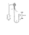
- FIG. 2 is a schematic cross-sectional view of the distal end portion of the endoscope shown in FIG.
- FIG. 3 is a schematic diagram illustrating an upper surface and a partial cross section of the tip portion of FIG. 2.
- FIG. 4 is a view of the distal end portion as viewed from the direction C in FIG.
- FIG. 5 is a schematic cross-sectional view showing a rising state of the tip portion of FIG.
- FIG. 6 is a diagram illustrating a rotation shaft and a raising base of an endoscope according to a modification of the first embodiment.
- FIG. 1 is a schematic diagram showing a configuration of an endoscope according to Embodiment 1 of the present invention.
- FIG. 2 is a schematic cross-sectional view of the distal end portion of the endoscope shown in FIG.
- FIG. 3 is a schematic diagram illustrating an upper surface and a partial cross section
- FIG. 7 is a schematic cross-sectional view of the distal end portion of the endoscope according to the second embodiment of the present invention.
- FIG. 8 is a schematic cross-sectional view showing a rising state of the tip portion of FIG.
- FIG. 9 is a schematic cross-sectional view of the distal end portion of an endoscope according to a modification of the second embodiment.
- FIG. 10 is a schematic cross-sectional view of the distal end portion of the endoscope according to the third embodiment of the present invention.
- an endoscope according to the present invention will be described below with reference to the drawings. Note that the present invention is not limited to these embodiments.
- the present invention can be generally applied to an endoscope using a treatment tool such as a puncture needle for performing a treatment in a subject.
- FIG. 1 is a schematic diagram showing a configuration of an endoscope according to Embodiment 1 of the present invention.
- the endoscope 1 is provided with an imaging unit at a distal end, an insertion unit 2 inserted into a subject, an operation unit 3 connected to a proximal end side of the insertion unit 2, and an operation unit 3.
- a universal cord 4 extending from the side, a connector portion connected to the universal cord 4 and connected to an observation device for controlling the endoscope 1 and a light source device for supplying illumination light to the endoscope 1 5 is provided.
- FIG. 1 is a schematic diagram showing a configuration of an endoscope according to Embodiment 1 of the present invention.
- the endoscope 1 is provided with an imaging unit at a distal end, an insertion unit 2 inserted into a subject, an operation unit 3 connected to a proximal end side of the insertion unit 2, and an operation unit 3.
- a universal cord 4 extending from the side, a connector portion connected to the universal cord 4 and connected
- insertion direction the direction in which the insertion portion 2 is inserted in the longitudinal direction of the endoscope is referred to as “insertion direction”, and the distal end side (upper side in FIG. 1) of the insertion direction is “ The “front end side” and the base end side (downward in FIG. 1) are defined as “base end side”.
- the insertion portion 2 includes, in order from the distal end side, a distal end portion 2a, a bending portion 2b configured to be bendable according to an operation of the operation portion 3, and a flexible tube portion 2c having flexibility.
- the proximal end of the flexible tube portion 2 c is connected to the distal end side of the operation portion 3.
- an elevator for raising the distal end of a treatment instrument described later is disposed on the distal end portion 2a.
- the operation unit 3 is provided with a treatment instrument insertion port 3a for inserting a puncture needle or the like, which is a treatment instrument, into the subject.
- a treatment instrument insertion passage is provided inside the insertion portion 2, and the treatment instrument insertion port 3a is an insertion port for the treatment instrument insertion passage.
- the operation unit 3 receives an operation for rotating a rotation shaft described later.
- FIG. 2 is a schematic cross-sectional view of the distal end portion of the endoscope shown in FIG.
- FIG. 3 is a schematic diagram illustrating an upper surface and a partial cross section of the tip portion of FIG. 2.
- FIG. 2 is a cross-sectional view corresponding to the line AA in FIG.
- FIG. 4 is a view of the distal end portion as viewed from the direction C in FIG.
- the distal end portion 2a includes a distal end rigid portion 101 disposed at the distal end of the distal end portion 2a, a treatment instrument channel 102 for projecting the treatment instrument from the distal end rigid portion 101, and a projection from the treatment instrument channel 102. And a rotating shaft 104 that rotatably supports the raising table 103. The raising table 103 raises the treatment tool to be raised. Further, as shown in FIG. 3, the distal end portion 2 a is disposed along the insertion direction, and is fitted to the rotating shaft 104 and the wire 105 that transmits the operation input to the operation portion 3 to the distal end portion 2 a. And a seal ring 106.
- FIG. 3 is a view in which a part of the hard tip portion 101 is removed so that the upper surfaces of the rotating shaft 104 and the wire 105 are exposed, and the central portion in FIG. 3 is a line BB in FIG. It is a figure showing a corresponding cross section.
- the tip hard portion 101 is made of a hard member such as resin or metal. As shown in FIG. 2, the distal end hard portion 101 is formed with an opening 101a for projecting the treatment instrument. The opening 101 a accommodates the elevator 103 and the rotating shaft 104. Further, as shown in FIG. 4, the distal end hard portion 101 has an opening 101 b for assembling the rotating shaft 104. The opening 101b is sealed with a lid (not shown) after the rotary shaft 104 is assembled.
- the treatment instrument channel 102 projects the treatment instrument inserted from the treatment instrument insertion port 3a of the operation unit 3 from the opening 101a of the distal end hard part 101.
- the elevator 103 is made of a metal such as stainless steel or an elastic member such as resin.
- the raising base 103 rotates with the rotation of the rotation shaft 104 by the operation of the operation unit 3 and raises the treatment instrument.
- the elevator 103 is extended along an attaching / detaching direction A1, which is a direction in which the elevator 103 described later is attached / detached, and is arranged at a pair of engaging portions 103a facing each other with the rotating shaft 104 interposed therebetween, and at the tip of each engaging portion 103a. And a pair of claw portions 103b that protrude from the engaging portion 103a to the rotating shaft 104 side. By engaging the claw portion 103 b with the rotating shaft 104, the raising base 103 is prevented from falling off the rotating shaft 104.
- the longitudinal direction of the elevator 103 and the attaching / detaching direction A1 which is the direction in which the engaging portion 103a extends, are the same direction.
- the rotating shaft 104 is disposed in the opening 101a and extends in a vertical direction on the paper surface of FIG. 3 (a direction perpendicular to the paper surface of FIG. 2), which is a direction of an axis perpendicular to the insertion direction.
- the shaft portion 104a supports the elevator 103 so as to be rotatable along the rotation direction A2.
- the shaft portion 104a has an engagement surface 104aa that extends along the attachment / detachment direction A1 and contacts the inner surface of the engagement portion 103a.
- the rotating shaft 104 has the wire connection part 104b to which the front-end
- the wire 105 is disposed along the insertion direction, is connected to the operation unit 3 on the proximal end side, and can be moved along the insertion direction by operation of the operation unit 3. Further, the wire 105 is connected to the wire connecting portion 104b of the rotating shaft 104 on the distal end side.
- the seal ring 106 is made of an elastic member such as rubber and is fitted into a groove formed in the rotating shaft 104. As a result, the wire connecting portion 104b and the wire 105 of the rotating shaft 104 are isolated from the outside and are not contaminated when the endoscope 1 is used.
- the operation in which the elevator 103 raises the treatment tool will be described.
- the wire 105 is pulled to the base end side (the left side in FIG. 4).
- the rotation shaft 104 rotates in the counterclockwise direction of FIG. 4 to the position of the broken line in FIG. 4 along the rotation direction A2.
- the raising base 103 and the rotating shaft 104 rotate integrally.
- FIG. 5 is a schematic cross-sectional view showing a rising state of the tip portion of FIG.
- the raising base 103 and the rotating shaft 104 rotate together to be in the raised state shown in FIG.
- the treatment tool that comes into contact with the elevator 103 is raised.
- a user applies a force for removing the elevator 103 from the rotating shaft 104 to the elevator 103 using tweezers or the like.
- This force is applied in a direction of pulling the elevator 103 along a predetermined attaching / detaching direction A1 perpendicular to the axis of the rotating shaft 104.
- the pair of engaging portions 103a of the raising base 103 having elasticity is deformed in a direction away from each other, and the engagement of the claw portion 103b with the rotating shaft 104 is released.
- the elevator 103 is detached from the rotating shaft 104 along the attaching / detaching direction A1 through the opening 101a.
- the user applies a force for attaching the elevator 103 to the rotating shaft 104 to the elevator 103 using tweezers or the like.
- This force is applied in the direction in which the elevator 103 is pushed in along the attaching / detaching direction A1.
- the pair of engaging portions 103a is deformed in a direction away from each other, so that the shaft portion 104a enters between the pair of engaging portions 103a.
- the claw portion 103b engages with the rotating shaft 104 due to the elasticity of the engaging portion 103a.
- the elevator 103 is prevented from falling off the rotating shaft 104, and the elevator 103 is attached to the rotating shaft 104 along the attaching / detaching direction A1 through the opening 101a.
- the elevator 103 can be easily attached to and detached from the rotating shaft 104 along the predetermined attaching / detaching direction A1 through the opening 101a.
- the endoscope 1 is configured such that the attaching / detaching direction A1 and the longitudinal direction of the elevator 103 coincide. Therefore, the user can intuitively grasp the attaching / detaching direction A1 when performing the attaching / detaching operation. As a result, it is possible to prevent the endoscope 1 from being damaged by applying a force in the wrong direction to the elevator 103 by the user.
- the elevator 103 is made of an elastic member, and can be attached to and detached from the rotating shaft 104 by the elasticity of the engaging portion 103a. For this reason, the raising base 103 only needs to have a configuration in which at least the engaging portion 103a is made of an elastic member, and the entire raising base 103 may not be made of an elastic member.
- the endoscope 1 according to the first embodiment can easily attach and detach the elevator 103 through the opening 101a.
- the elevator 103 can be removed after use of the endoscope 1 and directly cleaned with a brush, and the endoscope has good cleaning efficiency.
- the structure which keeps the raising stand 103 clean by using the raising stand 103 as a disposable member and attaching the new raising stand 103 after use may be sufficient.
- the rotating shaft 104 is exposed. As shown in FIG. 3, the rotating shaft 104 is a portion that needs to be cleaned because a portion of the shaft portion 104 a ahead of the seal ring 106 is exposed to the outside. Since this part does not have a complicated structure, it is easy to clean. Furthermore, as can be seen from FIG. 5, the endoscope 1 has a gap between the shaft portion 104 a and the distal end hard portion 101. As a result, the endoscope 1 can be cleaned directly by inserting a brush into the gap, and is an endoscope with good cleaning efficiency.
- FIG. 6 is a diagram illustrating a rotation shaft and a raising base of an endoscope according to a modification of the first embodiment.
- the raising base 103 is extended along the attaching / detaching direction, and is engaged with an engaging portion 103 a composed of a pair of elastic members that are opposed to each other with the rotating shaft 104 interposed therebetween.
- a rotating shaft 104 extending along the attaching / detaching direction and contacting the inner surface of the engaging portion 103a, and an engaging surface 104aa.
- the endoscope 1 only needs to include an engagement unit that prevents the elevator 103 from falling off the rotation shaft 104, and the shape thereof is not particularly limited.
- Embodiment 2 Next, an endoscope according to Embodiment 2 will be described. Since the endoscope according to the second embodiment has the same configuration as the endoscope 1 according to the first embodiment except for the configuration of the distal end portion 22a, the description thereof will be omitted as appropriate.
- FIG. 7 is a schematic cross-sectional view of the distal end portion of the endoscope according to the second embodiment of the present invention.
- the distal end portion 22a of the endoscope according to the second embodiment includes a distal end rigid portion 201 disposed at the distal end of the distal end portion 22a, and a treatment instrument that projects the treatment instrument from the distal end rigid portion 201.
- a channel 202, an elevator 203 for raising a treatment instrument protruding from the treatment instrument channel 202, and a rotating shaft 204 that rotatably supports the elevator 203 are provided.
- the opening portion 201 a for accommodating the raising base 203 is formed in the distal end hard portion 201.
- the treatment instrument channel 202 causes the treatment instrument inserted from the treatment instrument insertion port 3a of the operation unit 3 to protrude from the opening 201a of the distal end hard part 201.
- the raising base 203 rotates with the rotation of the rotating shaft 204 by the operation of the operation unit 3 and raises the treatment instrument.
- the elevator 203 extends along the attaching / detaching direction A3, and is disposed at a pair of engaging portions 203a facing each other with the rotating shaft 204 interposed therebetween, and at the tips of the engaging portions 203a.
- a pair of claw portions 203b protruding to the side.
- the longitudinal direction of the elevator 203 and the attaching / detaching direction A3 are different directions.
- the rotating shaft 204 has a cylindrical shaft portion 204a that is disposed in the opening 201a and extends in a direction perpendicular to the paper surface of FIG. 7 that is a direction of an axis perpendicular to the insertion direction. It supports so that it can rotate along rotation direction A4.
- the shaft portion 204a has an engagement surface 204aa that extends along the attachment / detachment direction A3 and contacts the inner surface of the engagement portion 203a.
- the rotating shaft 204 has a wire connection portion as described in Embodiment 1 with reference to FIG. 3, and rotates upon input of an operation from the wire connection portion.
- the wire connecting portion side of the rotating shaft 204 is isolated from the outside by a seal ring, and is an area that does not require cleaning.
- FIG. 8 is a schematic cross-sectional view showing the rising state of the tip of FIG.
- the wire is pulled to the proximal end side, whereby the rotating shaft 204 and the elevator base 203. And the elevator 203 are in a raised state.
- the raising base 203 can be easily attached to and detached from the rotating shaft 204 along the predetermined attaching / detaching direction A3 through the opening 201a.
- the endoscope according to the second embodiment is an endoscope with good cleaning efficiency because the elevator 203 can be removed and cleaned.
- the longitudinal direction of the elevator 203 and the attaching / detaching direction A3 are different directions, but the longitudinal direction of the elevator and the attaching / detaching direction do not necessarily coincide with each other.
- the endoscope according to the second embodiment may be configured to include an attaching / detaching direction display means for displaying the attaching / detaching direction A3.
- FIG. 9 is a schematic cross-sectional view of the distal end portion of an endoscope according to a modification of the second embodiment.
- the marker 203c as an attaching / detaching direction display means indicated by a broken line in FIG. 9 is provided by forming printing or unevenness on one or both side surfaces of the raising base 203.
- Embodiment 3 Next, an endoscope according to Embodiment 3 will be described. Since the endoscope according to the third embodiment has the same configuration as that of the endoscope 1 according to the first embodiment except for the configuration of the distal end portion 32a, description thereof will be omitted as appropriate.
- FIG. 10 is a schematic cross-sectional view of the distal end portion of the endoscope according to the third embodiment of the present invention.
- the distal end portion 32a of the endoscope according to the third embodiment includes a distal end rigid portion 301 disposed at the distal end of the distal end portion 32a, and a treatment instrument that projects the treatment instrument from the distal end rigid portion 301.
- a channel 302, an elevator 303 for raising a treatment instrument protruding from the treatment instrument channel 302, and a rotation shaft 304 for rotatably supporting the elevator 303 are provided.
- the opening rigid portion 301 is formed with an opening 301 a for accommodating the raising base 303.
- the treatment instrument channel 302 causes the treatment instrument inserted from the treatment instrument insertion port 3a of the operation unit 3 to protrude from the opening 301a of the distal end hard part 301.
- the raising base 303 rotates with the rotation of the rotary shaft 304 by the operation of the operation unit 3 to raise the treatment instrument.
- the raising base 303 extends along the attaching / detaching direction A5, and is disposed at a pair of engaging portions 303a facing each other with the rotating shaft 304 interposed therebetween, and at the tips of the engaging portions 303a.
- a pair of claw portions 303b protruding to the side.
- the raising base 303 has the protrusion part 303c extended along attachment / detachment direction A5 between a pair of engaging parts 303a.
- the rotating shaft 304 has a cylindrical shaft portion 304a that is disposed in the opening 301a and extends in a direction perpendicular to the paper surface of FIG. It supports so that it can rotate along rotation direction A6.
- the shaft portion 304a has an engagement surface 304aa that extends along the attachment / detachment direction A5 and that contacts the inner surface of the engagement portion 303a.
- the shaft part 304a has a groove part 304ab into which the protruding part 303c is inserted.
- the rotating shaft 304 has a wire connecting portion similar to that described in Embodiment 1 with reference to FIG. 3, and rotates upon input of an operation from the wire connecting portion.
- the wire connecting portion side of the rotating shaft 304 is isolated from the outside by a seal ring, and is an area that does not require cleaning.
- the endoscope according to the third embodiment as in the first embodiment, when a predetermined operation is input to the operation unit 3, the wire is pulled to the proximal end side, whereby the rotating shaft 304 and the raising base 303. , And the elevator 303 is in the raised state.
- the protrusion 303c of the elevator 303 and the groove 304ab of the rotating shaft 304 function as rotation preventing means that are fitted to each other and prevent the elevator 303 and the rotating shaft 304 from rotating relative to each other. Therefore, the elevator 303 and the rotary shaft 304 are prevented from rotating relative to each other when the endoscope is used, and the elevator 303 is prevented from falling off the rotary shaft 304.
- the endoscope may be configured to include rotation preventing means for preventing relative rotation between the elevator 303 and the rotating shaft 304.
- the rotation preventing means is not limited to the protrusion and the groove, and may be, for example, a rod and a hole, or unevenness that fits each other.
- the structure which the raising base 303 has a groove part and the rotating shaft 304 has a projection part may be sufficient.
- the raising base 303 can be easily attached to and detached from the rotating shaft 304 along the predetermined attaching / detaching direction A5 through the opening 301a.
- the endoscope according to the third embodiment is an endoscope with good cleaning efficiency because the elevator 303 can be removed and cleaned.
- the configuration of the above-described embodiment can be applied to an ultrasonic endoscope including an ultrasonic transducer disposed at the distal end of the insertion portion.
- a vibrator is disposed at the tip, and a cable connected to the vibrator passes below the opening of the hard tip portion. For this reason, it is difficult to achieve a structure that can be disassembled for cleaning while ensuring the watertightness of the tip including the vibrator.
- tip part may enlarge. Therefore, even in an ultrasonic endoscope, by applying the configuration of the above-described embodiment, it is possible to remove and lift the raising base without disassembling the distal end portion, and the ultrasonic endoscope having good cleaning efficiency. Can be realized.
Abstract
An endoscope into which a treatment instrument can be inserted, wherein the endoscope is provided with: a distal end hard section disposed at the distal end of the endoscope and having an opening formed in the distal end hard section, the opening allowing the treatment instrument to protrude therefrom; a rotatable shaft disposed within the opening and having an axis perpendicular to the longitudinal direction of the endoscope; an operating section for receiving the operation of rotating the rotatable shaft; and a raising base capable of being mounted to and removed from the rotatable shaft through the opening in a predetermined mounting and removal direction and raising the treatment instrument as the rotatable shaft rotates. The provided endoscope can be cleaned with good cleaning efficiency.
Description
本発明は、内視鏡に関する。
The present invention relates to an endoscope.
従来、被検体内に挿入されて被検部位の観察等を行う内視鏡が知られており、医療分野等で広く利用されている。近年の内視鏡には、被検体内の処置を行なう穿刺針等の処置具を患部へ向けるための起上台を備えたものがある。例えば、特許文献1には、回転軸に回転可能に支持された起上台が開示されている。この技術では、起上台に接続された操作用のワイヤを基端側に引っ張ることによって、起上台が回転し、処置具を起上させる。
2. Description of the Related Art Conventionally, endoscopes that are inserted into a subject to observe a region to be examined are known and widely used in the medical field and the like. Some recent endoscopes include an elevator for directing a treatment tool such as a puncture needle for performing a treatment in a subject to an affected area. For example, Patent Document 1 discloses an elevator that is rotatably supported on a rotating shaft. In this technique, by pulling the operation wire connected to the elevator to the proximal end side, the elevator is rotated and the treatment instrument is raised.
ところで、内視鏡は、感染症の伝播を予防するため、十分に洗浄したうえで消毒や滅菌をする必要があり、十分に洗浄を行うことが重要である。上述した起上台を有する内視鏡において、起上台の側部や裏側を十分に洗浄するには、内視鏡の先端部を分解しなければならず、洗浄効率が悪いという課題があった。
By the way, in order to prevent the transmission of infectious diseases, it is necessary to disinfect and sterilize the endoscope sufficiently, and it is important to thoroughly wash the endoscope. In the endoscope having the above-described elevator, in order to sufficiently clean the side and the back side of the elevator, the tip of the endoscope has to be disassembled, which has a problem of poor cleaning efficiency.
本発明は、上記に鑑みてなされたものであって、洗浄効率が良好な内視鏡を提供することを目的とする。
The present invention has been made in view of the above, and an object thereof is to provide an endoscope having good cleaning efficiency.
上述した課題を解決し、目的を達成するために、本発明の一態様に係る内視鏡は、処置具を挿入可能な内視鏡において、前記内視鏡の先端に配設され、前記処置具を突出させる開口部が形成された先端硬質部と、前記開口部内に配設され、軸心の方向と前記内視鏡の長手方向とが直交する回転軸と、前記回転軸を回転させる操作を受け付ける操作部と、前記開口部を介して所定の着脱方向に沿って前記回転軸に着脱可能であり、前記回転軸の回転に伴って前記処置具を起上する起上台と、を備えることを特徴とする。
In order to solve the above-described problems and achieve the object, an endoscope according to one aspect of the present invention is an endoscope in which a treatment tool can be inserted, which is disposed at a distal end of the endoscope, and the treatment A hard distal end formed with an opening for projecting the tool, a rotation shaft disposed in the opening, the direction of the axis being perpendicular to the longitudinal direction of the endoscope, and an operation of rotating the rotation shaft And an elevator that is detachable from the rotating shaft along a predetermined attaching / detaching direction via the opening, and raises the treatment instrument as the rotating shaft rotates. It is characterized by.
また、本発明の一態様に係る内視鏡は、前記起上台は、前記着脱方向に沿って延伸し、前記回転軸を挟んで対向する一対の弾性部材からなる係合部と、各係合部の先端に配設され、前記係合部から前記回転軸側に突出した爪部と、を有し、前記回転軸は、前記着脱方向に沿って延伸するとともに前記係合部の内面と当接する係合面を有することを特徴とする。
In the endoscope according to one aspect of the present invention, the raising base extends along the attachment / detachment direction, and includes an engagement portion formed of a pair of elastic members facing each other with the rotation shaft interposed therebetween, and each engagement. A claw portion disposed at a distal end of the portion and projecting from the engagement portion toward the rotation shaft, and the rotation shaft extends along the attachment / detachment direction and contacts the inner surface of the engagement portion. It has the engagement surface which touches, It is characterized by the above-mentioned.
また、本発明の一態様に係る内視鏡は、前記起上台は、前記着脱方向に沿って延伸し、前記回転軸を挟んで対向する一対の弾性部材からなる係合部と、前記係合部が対向する方向の内側に設けられた凹部と、を有し、前記回転軸は、前記着脱方向に沿って延伸するとともに前記係合部の内面と当接する係合面と、前記係合面から前記係合部側へ突出して前記起上台の前記凹部と係合する凸部と、を有することを特徴とする。
In the endoscope according to one aspect of the present invention, the raising base extends along the attachment / detachment direction, and includes an engagement portion including a pair of elastic members facing each other with the rotation shaft interposed therebetween, and the engagement A concave portion provided on the inner side in a direction in which the portions face each other, the rotating shaft extending along the attaching / detaching direction and contacting an inner surface of the engaging portion, and the engaging surface And a convex portion that protrudes toward the engaging portion side and engages with the concave portion of the raising base.
また、本発明の一態様に係る内視鏡は、前記起上台の長手方向と、前記係合部が延伸する方向とが同一の方向であることを特徴とする。
The endoscope according to one aspect of the present invention is characterized in that the longitudinal direction of the raising base and the direction in which the engaging portion extends are the same direction.
また、本発明の一態様に係る内視鏡は、前記起上台は、前記着脱方向を示す着脱方向表示手段を有することを特徴とする。
Further, the endoscope according to one aspect of the present invention is characterized in that the raising base has an attaching / detaching direction display means for indicating the attaching / detaching direction.
また、本発明の一態様に係る内視鏡は、前記起上台と前記回転軸とが相対回転することを防止する回転防止手段をさらに備えることを特徴とする。
The endoscope according to one aspect of the present invention is further characterized by further comprising a rotation preventing means for preventing the elevator and the rotating shaft from rotating relative to each other.
また、本発明の一態様に係る内視鏡は、前記回転防止手段は、前記起上台と前記回転軸とのいずれか一方に形成された溝部と、前記起上台と前記回転軸との他方に形成された突起部と、を有することを特徴とする。
The endoscope according to one aspect of the present invention may be configured such that the rotation preventing means is provided on a groove formed in one of the elevator and the rotation shaft, and on the other of the elevator and the rotation shaft. And a protruding portion formed.
また、本発明の一態様に係る内視鏡は、先端に配設された超音波振動子をさらに備える超音波内視鏡であることを特徴とする。
Further, the endoscope according to one aspect of the present invention is an ultrasonic endoscope further including an ultrasonic transducer disposed at a distal end.
本発明によれば、洗浄効率が良好な内視鏡を実現することができる。
According to the present invention, an endoscope with good cleaning efficiency can be realized.
以下に、図面を参照して本発明に係る内視鏡の実施の形態を説明する。なお、これらの実施の形態により本発明が限定されるものではない。本発明は、被検体内の処置を行なうための穿刺針等の処置具を用いる内視鏡一般に適用することができる。
Embodiments of an endoscope according to the present invention will be described below with reference to the drawings. Note that the present invention is not limited to these embodiments. The present invention can be generally applied to an endoscope using a treatment tool such as a puncture needle for performing a treatment in a subject.
また、図面の記載において、同一又は対応する要素には適宜同一の符号を付している。また、図面は模式的なものであり、各要素の寸法の関係、各要素の比率などは、現実と異なる場合があることに留意する必要がある。図面の相互間においても、互いの寸法の関係や比率が異なる部分が含まれている場合がある。
In the description of the drawings, the same or corresponding elements are appropriately denoted by the same reference numerals. It should be noted that the drawings are schematic, and the relationship between the dimensions of each element, the ratio of each element, and the like may differ from the actual situation. Even between the drawings, there are cases in which portions having different dimensional relationships and ratios are included.
(実施の形態1)
図1は、本発明の実施の形態1に係る内視鏡の構成を示す模式図である。内視鏡1は、先端に撮像部が配設され、被検体内に挿入される挿入部2と、この挿入部2の基端側に連設された操作部3と、この操作部3の側部から延出するユニバーサルコード4と、ユニバーサルコード4に連設され、内視鏡1を制御する観察装置及び内視鏡1に照明光を供給するための光源装置等と接続されるコネクタ部5と、を備える。なお、本明細書において、図1に示すように、内視鏡の長手方向であって挿入部2を挿入する方向を「挿入方向」とし、挿入方向の先端側(図1の上方)を「先端側」、基端側(図1の下方)を「基端側」とする。 (Embodiment 1)
FIG. 1 is a schematic diagram showing a configuration of an endoscope according to Embodiment 1 of the present invention. The endoscope 1 is provided with an imaging unit at a distal end, aninsertion unit 2 inserted into a subject, an operation unit 3 connected to a proximal end side of the insertion unit 2, and an operation unit 3. A universal cord 4 extending from the side, a connector portion connected to the universal cord 4 and connected to an observation device for controlling the endoscope 1 and a light source device for supplying illumination light to the endoscope 1 5 is provided. In this specification, as shown in FIG. 1, the direction in which the insertion portion 2 is inserted in the longitudinal direction of the endoscope is referred to as “insertion direction”, and the distal end side (upper side in FIG. 1) of the insertion direction is “ The “front end side” and the base end side (downward in FIG. 1) are defined as “base end side”.
図1は、本発明の実施の形態1に係る内視鏡の構成を示す模式図である。内視鏡1は、先端に撮像部が配設され、被検体内に挿入される挿入部2と、この挿入部2の基端側に連設された操作部3と、この操作部3の側部から延出するユニバーサルコード4と、ユニバーサルコード4に連設され、内視鏡1を制御する観察装置及び内視鏡1に照明光を供給するための光源装置等と接続されるコネクタ部5と、を備える。なお、本明細書において、図1に示すように、内視鏡の長手方向であって挿入部2を挿入する方向を「挿入方向」とし、挿入方向の先端側(図1の上方)を「先端側」、基端側(図1の下方)を「基端側」とする。 (Embodiment 1)
FIG. 1 is a schematic diagram showing a configuration of an endoscope according to Embodiment 1 of the present invention. The endoscope 1 is provided with an imaging unit at a distal end, an
挿入部2は、先端側から順に、先端部2aと、操作部3の操作に応じて湾曲自在に構成された湾曲部2bと、可撓性を有する可撓管部2cと、を有する。可撓管部2cの基端は、操作部3の先端側に連設されている。先端部2aには、後述する処置具の先端を起上させるための起上台が配設される。
The insertion portion 2 includes, in order from the distal end side, a distal end portion 2a, a bending portion 2b configured to be bendable according to an operation of the operation portion 3, and a flexible tube portion 2c having flexibility. The proximal end of the flexible tube portion 2 c is connected to the distal end side of the operation portion 3. On the distal end portion 2a, an elevator for raising the distal end of a treatment instrument described later is disposed.
操作部3には、処置具である穿刺針等を被検体内へと挿入するための処置具挿入口3aが設けられている。挿入部2の内部には処置具挿通路が設けられており、処置具挿入口3aは、処置具挿通路の挿入口になっている。また、操作部3は、後述する回転軸を回転させる操作を受け付ける。
The operation unit 3 is provided with a treatment instrument insertion port 3a for inserting a puncture needle or the like, which is a treatment instrument, into the subject. A treatment instrument insertion passage is provided inside the insertion portion 2, and the treatment instrument insertion port 3a is an insertion port for the treatment instrument insertion passage. In addition, the operation unit 3 receives an operation for rotating a rotation shaft described later.
図2は、図1に示す内視鏡の先端部の模式的な断面図である。図3は、図2の先端部の上面及び部分断面を表す模式図である。図2は、図3のA-A線に対応する断面図である。図4は、先端部を図3のC方向から見た図である。
FIG. 2 is a schematic cross-sectional view of the distal end portion of the endoscope shown in FIG. FIG. 3 is a schematic diagram illustrating an upper surface and a partial cross section of the tip portion of FIG. 2. FIG. 2 is a cross-sectional view corresponding to the line AA in FIG. FIG. 4 is a view of the distal end portion as viewed from the direction C in FIG.
先端部2aは、図2に示すように、先端部2aの先端に配設された先端硬質部101と、先端硬質部101から処置具を突出させる処置具チャンネル102と、処置具チャンネル102から突出する処置具を起上させる起上台103と、起上台103を回転可能に支持する回転軸104と、を備える。また、先端部2aは、図3に示すように、挿入方向に沿って配設され、操作部3に入力された操作を先端部2aへ伝達するワイヤ105と、回転軸104に嵌装されたシールリング106と、を備える。なお、図3の上部は、回転軸104及びワイヤ105の上面が露出するように先端硬質部101の一部を取り除いた図であり、図3の中央部は、図2のB-B線に対応する断面を表す図である。
As shown in FIG. 2, the distal end portion 2a includes a distal end rigid portion 101 disposed at the distal end of the distal end portion 2a, a treatment instrument channel 102 for projecting the treatment instrument from the distal end rigid portion 101, and a projection from the treatment instrument channel 102. And a rotating shaft 104 that rotatably supports the raising table 103. The raising table 103 raises the treatment tool to be raised. Further, as shown in FIG. 3, the distal end portion 2 a is disposed along the insertion direction, and is fitted to the rotating shaft 104 and the wire 105 that transmits the operation input to the operation portion 3 to the distal end portion 2 a. And a seal ring 106. 3 is a view in which a part of the hard tip portion 101 is removed so that the upper surfaces of the rotating shaft 104 and the wire 105 are exposed, and the central portion in FIG. 3 is a line BB in FIG. It is a figure showing a corresponding cross section.
先端硬質部101は、樹脂、金属等の硬質部材からなる。図2に示すように、先端硬質部101には、処置具を突出させる開口部101aが形成されている。開口部101aは、起上台103及び回転軸104を収容する。また、先端硬質部101は、図4に示すように、回転軸104を組み付けるための開口部101bを有する。この開口部101bは、回転軸104が組み付けられた後、不図示の蓋で密閉される。
The tip hard portion 101 is made of a hard member such as resin or metal. As shown in FIG. 2, the distal end hard portion 101 is formed with an opening 101a for projecting the treatment instrument. The opening 101 a accommodates the elevator 103 and the rotating shaft 104. Further, as shown in FIG. 4, the distal end hard portion 101 has an opening 101 b for assembling the rotating shaft 104. The opening 101b is sealed with a lid (not shown) after the rotary shaft 104 is assembled.
処置具チャンネル102は、操作部3の処置具挿入口3aから挿入された処置具を先端硬質部101の開口部101aから突出させる。
The treatment instrument channel 102 projects the treatment instrument inserted from the treatment instrument insertion port 3a of the operation unit 3 from the opening 101a of the distal end hard part 101.
起上台103は、ステンレス等の金属又は樹脂等の弾性部材からなる。起上台103は、操作部3の操作により回転軸104の回転に伴って回転し、処置具を起上させる。起上台103は、後述する起上台103を着脱する方向である着脱方向A1に沿って延伸し、回転軸104を挟んで対向する一対の係合部103aと、各係合部103aの先端に配設され、係合部103aから回転軸104側に突出する一対の爪部103bと、を有する。この爪部103bが回転軸104と係合することにより、起上台103が回転軸104から脱落することが防止されている。また、起上台103では、起上台103の長手方向と係合部103aが延伸する方向である着脱方向A1とが同一の方向である。
The elevator 103 is made of a metal such as stainless steel or an elastic member such as resin. The raising base 103 rotates with the rotation of the rotation shaft 104 by the operation of the operation unit 3 and raises the treatment instrument. The elevator 103 is extended along an attaching / detaching direction A1, which is a direction in which the elevator 103 described later is attached / detached, and is arranged at a pair of engaging portions 103a facing each other with the rotating shaft 104 interposed therebetween, and at the tip of each engaging portion 103a. And a pair of claw portions 103b that protrude from the engaging portion 103a to the rotating shaft 104 side. By engaging the claw portion 103 b with the rotating shaft 104, the raising base 103 is prevented from falling off the rotating shaft 104. In the elevator 103, the longitudinal direction of the elevator 103 and the attaching / detaching direction A1, which is the direction in which the engaging portion 103a extends, are the same direction.
回転軸104は、開口部101a内に配設され、挿入方向と直交する軸心の方向である図3の紙面上下方向(図2の紙面に垂直な方向)に延伸する円柱形状の軸部104aを有する。軸部104aは、起上台103を回転方向A2に沿って回転可能に支持する。軸部104aは、着脱方向A1に沿って延伸するとともに係合部103aの内面と当接する係合面104aaを有する。また、回転軸104は、図3に示すように、ワイヤ105の先端部が接続されるワイヤ接続部104bを有する。
The rotating shaft 104 is disposed in the opening 101a and extends in a vertical direction on the paper surface of FIG. 3 (a direction perpendicular to the paper surface of FIG. 2), which is a direction of an axis perpendicular to the insertion direction. Have The shaft portion 104a supports the elevator 103 so as to be rotatable along the rotation direction A2. The shaft portion 104a has an engagement surface 104aa that extends along the attachment / detachment direction A1 and contacts the inner surface of the engagement portion 103a. Moreover, the rotating shaft 104 has the wire connection part 104b to which the front-end | tip part of the wire 105 is connected, as shown in FIG.
ここで、起上台103の係合部103aと回転軸104の係合面104aaとが回転方向A2と直交する方向に沿って当接していることにより、起上台103と回転軸104とが相対回転することが防止されている。
Here, since the engaging portion 103a of the elevator 103 and the engaging surface 104aa of the rotating shaft 104 are in contact with each other along the direction orthogonal to the rotation direction A2, the elevator 103 and the rotating shaft 104 are relatively rotated. Is prevented.
ワイヤ105は、図3に示すように、挿入方向に沿って配設され、基端側で操作部3と接続され、操作部3の操作により挿入方向に沿って移動可能である。また、ワイヤ105は、先端側で回転軸104のワイヤ接続部104bに接続される。
As shown in FIG. 3, the wire 105 is disposed along the insertion direction, is connected to the operation unit 3 on the proximal end side, and can be moved along the insertion direction by operation of the operation unit 3. Further, the wire 105 is connected to the wire connecting portion 104b of the rotating shaft 104 on the distal end side.
シールリング106は、ゴム等の弾性部材からなり、回転軸104に形成された溝に嵌装される。その結果、回転軸104のワイヤ接続部104b及びワイヤ105が外部から隔離され、内視鏡1の使用時に汚染されることがない。
The seal ring 106 is made of an elastic member such as rubber and is fitted into a groove formed in the rotating shaft 104. As a result, the wire connecting portion 104b and the wire 105 of the rotating shaft 104 are isolated from the outside and are not contaminated when the endoscope 1 is used.
次に、起上台103が処置具を起上させる動作について説明する。まず、操作部3に所定の操作が入力されると、ワイヤ105が基端側(図4の紙面左側)に引っ張られる。ワイヤ105が挿入方向に沿って基端側に移動すると、図4に示すように、回転軸104が回転方向A2に沿って図4の反時計回りの方向に図4の破線の位置まで回転する。さらに、起上台103と回転軸104とは、一体となって回転する。
Next, the operation in which the elevator 103 raises the treatment tool will be described. First, when a predetermined operation is input to the operation unit 3, the wire 105 is pulled to the base end side (the left side in FIG. 4). When the wire 105 moves to the proximal end side along the insertion direction, as shown in FIG. 4, the rotation shaft 104 rotates in the counterclockwise direction of FIG. 4 to the position of the broken line in FIG. 4 along the rotation direction A2. . Furthermore, the raising base 103 and the rotating shaft 104 rotate integrally.
図5は、図2の先端部の起上状態を表す模式的な断面図である。起上台103と回転軸104とは、一体となって回転し、図5に示す起上状態となる。そして、起上台103が起上すると、起上台103と当接する処置具が起上する。
FIG. 5 is a schematic cross-sectional view showing a rising state of the tip portion of FIG. The raising base 103 and the rotating shaft 104 rotate together to be in the raised state shown in FIG. When the elevator 103 is raised, the treatment tool that comes into contact with the elevator 103 is raised.
次に、起上台103を回転軸104から着脱する動作について説明する。
Next, an operation for attaching and detaching the elevator 103 from the rotating shaft 104 will be described.
まず、回転軸104から起上台103を取り外す動作について説明する。はじめに、ユーザがピンセット等を用いて起上台103に、起上台103を回転軸104から取り外すための力を加える。この力は、回転軸104の軸心に対して垂直な所定の着脱方向A1に沿って、起上台103を引っ張る方向に加えられる。すると、この力により、弾性を有する起上台103の一対の係合部103aが互いに離間する方向に変形し、爪部103bの回転軸104への係合が解除される。その結果、起上台103が、開口部101aを介して着脱方向A1に沿って回転軸104から取り外される。
First, the operation of removing the elevator 103 from the rotating shaft 104 will be described. First, a user applies a force for removing the elevator 103 from the rotating shaft 104 to the elevator 103 using tweezers or the like. This force is applied in a direction of pulling the elevator 103 along a predetermined attaching / detaching direction A1 perpendicular to the axis of the rotating shaft 104. Then, by this force, the pair of engaging portions 103a of the raising base 103 having elasticity is deformed in a direction away from each other, and the engagement of the claw portion 103b with the rotating shaft 104 is released. As a result, the elevator 103 is detached from the rotating shaft 104 along the attaching / detaching direction A1 through the opening 101a.
続いて、起上台103を回転軸104に取り付ける動作について説明する。はじめに、ユーザがピンセット等を用いて起上台103に、起上台103を回転軸104に取り付けるための力を加える。この力は、着脱方向A1に沿って、起上台103を押し込む方向に加えられる。すると、この力により、一対の係合部103aが互いに離間する方向に変形することで、一対の係合部103aの間に軸部104aが進入する。さらに、軸部104aが係合部103aの最深部まで進入すると、係合部103aの弾性により爪部103bが回転軸104と係合する。その結果、起上台103が回転軸104から脱落することが防止され、起上台103が、開口部101aを介して着脱方向A1に沿って回転軸104に取り付けられる。
Subsequently, the operation of attaching the elevator 103 to the rotating shaft 104 will be described. First, the user applies a force for attaching the elevator 103 to the rotating shaft 104 to the elevator 103 using tweezers or the like. This force is applied in the direction in which the elevator 103 is pushed in along the attaching / detaching direction A1. Then, by this force, the pair of engaging portions 103a is deformed in a direction away from each other, so that the shaft portion 104a enters between the pair of engaging portions 103a. Further, when the shaft portion 104a enters the deepest portion of the engaging portion 103a, the claw portion 103b engages with the rotating shaft 104 due to the elasticity of the engaging portion 103a. As a result, the elevator 103 is prevented from falling off the rotating shaft 104, and the elevator 103 is attached to the rotating shaft 104 along the attaching / detaching direction A1 through the opening 101a.
従って、起上台103は、開口部101aを介して所定の着脱方向A1に沿って回転軸104に容易に着脱可能である。
Therefore, the elevator 103 can be easily attached to and detached from the rotating shaft 104 along the predetermined attaching / detaching direction A1 through the opening 101a.
なお、内視鏡1は、着脱方向A1と起上台103の長手方向とが一致する構成とされている。そのため、ユーザは、着脱する動作を行う際に、着脱方向A1を直感的に把握することができる。その結果、ユーザが起上台103に誤った方向の力を加え、内視鏡1が破損することが防止されている。
Note that the endoscope 1 is configured such that the attaching / detaching direction A1 and the longitudinal direction of the elevator 103 coincide. Therefore, the user can intuitively grasp the attaching / detaching direction A1 when performing the attaching / detaching operation. As a result, it is possible to prevent the endoscope 1 from being damaged by applying a force in the wrong direction to the elevator 103 by the user.
また、起上台103は、弾性部材からなり、係合部103aの弾性により回転軸104に着脱可能とされている。そのため、起上台103は、少なくとも係合部103aが弾性部材からなる構成であればよく、起上台103全体が弾性部材からなる構成でなくてもよい。
Further, the elevator 103 is made of an elastic member, and can be attached to and detached from the rotating shaft 104 by the elasticity of the engaging portion 103a. For this reason, the raising base 103 only needs to have a configuration in which at least the engaging portion 103a is made of an elastic member, and the entire raising base 103 may not be made of an elastic member.
以上説明したように、本実施の形態1に係る内視鏡1は、開口部101aを介して、起上台103を容易に着脱することができる。その結果、内視鏡1の使用後に起上台103を取り外してブラシで直接洗浄することができ、洗浄効率が良好な内視鏡である。
As described above, the endoscope 1 according to the first embodiment can easily attach and detach the elevator 103 through the opening 101a. As a result, the elevator 103 can be removed after use of the endoscope 1 and directly cleaned with a brush, and the endoscope has good cleaning efficiency.
なお、起上台103を使い捨ての部材とし、使用後は新しい起上台103を装着することで、起上台103を清潔に保つ構成であってもよい。
In addition, the structure which keeps the raising stand 103 clean by using the raising stand 103 as a disposable member and attaching the new raising stand 103 after use may be sufficient.
また、起上台103を取り外すと回転軸104が露出する。回転軸104は、図3に示すように、軸部104aのシールリング106より先の部分が外部に露出しており、洗浄が必要な部分である。この部分は複雑な構造を有さないため、洗浄が容易である。さらに、図5からわかるように、内視鏡1は、軸部104aと先端硬質部101との間に隙間を有する。その結果、内視鏡1は、この隙間にブラシを挿入して直接洗浄することができ、洗浄効率が良好な内視鏡である。
Also, when the elevator 103 is removed, the rotating shaft 104 is exposed. As shown in FIG. 3, the rotating shaft 104 is a portion that needs to be cleaned because a portion of the shaft portion 104 a ahead of the seal ring 106 is exposed to the outside. Since this part does not have a complicated structure, it is easy to clean. Furthermore, as can be seen from FIG. 5, the endoscope 1 has a gap between the shaft portion 104 a and the distal end hard portion 101. As a result, the endoscope 1 can be cleaned directly by inserting a brush into the gap, and is an endoscope with good cleaning efficiency.
なお、実施の形態1に係る内視鏡1は、起上台103の爪部103bが回転軸104と係合する構成に限られない。図6は、実施の形態1の変形例に係る内視鏡の回転軸及び起上台を表す図である。図6に示すように、変形例の内視鏡1において、起上台103は、着脱方向に沿って延伸し、回転軸104を挟んで対向する一対の弾性部材からなる係合部103aと、係合部103aが対向する方向の内側に設けられた凹部103cと、を有し、回転軸104は、着脱方向に沿って延伸するとともに係合部103aの内面と当接する係合面104aaと、係合面104aaから係合部103a側へ突出して起上台103の凹部103cと係合する凸部104abと、を有する。その結果、起上台103の凹部103cと回転軸104の凸部104abとが係合することにより、起上台103が回転軸104から脱落することを防止する構成である。このように、内視鏡1は、起上台103が回転軸104から脱落することを防止する係合手段を備えればよく、特にその形状は限定されない。
Note that the endoscope 1 according to the first embodiment is not limited to the configuration in which the claw portion 103b of the elevator 103 is engaged with the rotation shaft 104. FIG. 6 is a diagram illustrating a rotation shaft and a raising base of an endoscope according to a modification of the first embodiment. As shown in FIG. 6, in the endoscope 1 of the modified example, the raising base 103 is extended along the attaching / detaching direction, and is engaged with an engaging portion 103 a composed of a pair of elastic members that are opposed to each other with the rotating shaft 104 interposed therebetween. A rotating shaft 104 extending along the attaching / detaching direction and contacting the inner surface of the engaging portion 103a, and an engaging surface 104aa. And a convex portion 104ab that protrudes from the mating surface 104aa toward the engaging portion 103a and engages with the concave portion 103c of the elevator 103. As a result, the recess 103c of the elevator 103 and the protrusion 104ab of the rotating shaft 104 are engaged to prevent the elevator 103 from falling off the rotating shaft 104. Thus, the endoscope 1 only needs to include an engagement unit that prevents the elevator 103 from falling off the rotation shaft 104, and the shape thereof is not particularly limited.
(実施の形態2)
次に、実施の形態2に係る内視鏡について説明する。実施の形態2に係る内視鏡は、先端部22aの構成を除いて、実施の形態1に係る内視鏡1と同様の構成を備えるので、適宜説明を省略する。 (Embodiment 2)
Next, an endoscope according toEmbodiment 2 will be described. Since the endoscope according to the second embodiment has the same configuration as the endoscope 1 according to the first embodiment except for the configuration of the distal end portion 22a, the description thereof will be omitted as appropriate.
次に、実施の形態2に係る内視鏡について説明する。実施の形態2に係る内視鏡は、先端部22aの構成を除いて、実施の形態1に係る内視鏡1と同様の構成を備えるので、適宜説明を省略する。 (Embodiment 2)
Next, an endoscope according to
図7は、本発明の実施の形態2に係る内視鏡の先端部の模式的な断面図である。図7に示すように、実施の形態2に係る内視鏡の先端部22aは、先端部22aの先端に配設された先端硬質部201と、先端硬質部201から処置具を突出させる処置具チャンネル202と、処置具チャンネル202から突出する処置具を起上させる起上台203と、起上台203を回転可能に支持する回転軸204と、を備える。
FIG. 7 is a schematic cross-sectional view of the distal end portion of the endoscope according to the second embodiment of the present invention. As shown in FIG. 7, the distal end portion 22a of the endoscope according to the second embodiment includes a distal end rigid portion 201 disposed at the distal end of the distal end portion 22a, and a treatment instrument that projects the treatment instrument from the distal end rigid portion 201. A channel 202, an elevator 203 for raising a treatment instrument protruding from the treatment instrument channel 202, and a rotating shaft 204 that rotatably supports the elevator 203 are provided.
先端硬質部201には、起上台203を収容する開口部201aが形成されている。
The opening portion 201 a for accommodating the raising base 203 is formed in the distal end hard portion 201.
処置具チャンネル202は、操作部3の処置具挿入口3aから挿入された処置具を先端硬質部201の開口部201aから突出させる。
The treatment instrument channel 202 causes the treatment instrument inserted from the treatment instrument insertion port 3a of the operation unit 3 to protrude from the opening 201a of the distal end hard part 201.
起上台203は、操作部3の操作により回転軸204の回転に伴って回転し、処置具を起上させる。起上台203は、着脱方向A3に沿って延伸し、回転軸204を挟んで対向する一対の係合部203aと、各係合部203aの先端に配設され、係合部203aから回転軸204側に突出する一対の爪部203bと、を有する。なお、この起上台203において、起上台203の長手方向と着脱方向A3とは、異なる方向である。
The raising base 203 rotates with the rotation of the rotating shaft 204 by the operation of the operation unit 3 and raises the treatment instrument. The elevator 203 extends along the attaching / detaching direction A3, and is disposed at a pair of engaging portions 203a facing each other with the rotating shaft 204 interposed therebetween, and at the tips of the engaging portions 203a. A pair of claw portions 203b protruding to the side. In this elevator 203, the longitudinal direction of the elevator 203 and the attaching / detaching direction A3 are different directions.
回転軸204は、開口部201a内に配設され、挿入方向と直交する軸心の方向である図7の紙面に垂直な方向に延伸する円柱形状の軸部204aを有し、起上台203を回転方向A4に沿って回転可能に支持する。軸部204aは、着脱方向A3に沿って延伸するとともに係合部203aの内面と当接する係合面204aaを有する。なお、回転軸204は、図3を用いて実施の形態1で説明したのと同様にワイヤ接続部を有し、ワイヤ接続部からの操作を入力されて回転する。また、実施の形態1と同様に、回転軸204のワイヤ接続部側はシールリングにより外部から隔離されており、洗浄が不要な領域とされている。
The rotating shaft 204 has a cylindrical shaft portion 204a that is disposed in the opening 201a and extends in a direction perpendicular to the paper surface of FIG. 7 that is a direction of an axis perpendicular to the insertion direction. It supports so that it can rotate along rotation direction A4. The shaft portion 204a has an engagement surface 204aa that extends along the attachment / detachment direction A3 and contacts the inner surface of the engagement portion 203a. The rotating shaft 204 has a wire connection portion as described in Embodiment 1 with reference to FIG. 3, and rotates upon input of an operation from the wire connection portion. Similarly to the first embodiment, the wire connecting portion side of the rotating shaft 204 is isolated from the outside by a seal ring, and is an area that does not require cleaning.
図8は、図7の先端部の起上状態を表す模式的な断面図である。実施の形態2に係る内視鏡は、実施の形態1と同様に、操作部3に所定の操作が入力されると、ワイヤが基端側に引っ張られることにより、回転軸204と起上台203とが一体となって回転し、起上台203が起上状態となる。
FIG. 8 is a schematic cross-sectional view showing the rising state of the tip of FIG. In the endoscope according to the second embodiment, as in the first embodiment, when a predetermined operation is input to the operation unit 3, the wire is pulled to the proximal end side, whereby the rotating shaft 204 and the elevator base 203. And the elevator 203 are in a raised state.
また、図8に破線で示すように、実施の形態1と同様に、起上台203は、開口部201aを介して所定の着脱方向A3に沿って回転軸204に容易に着脱可能である。その結果、実施の形態2に係る内視鏡は、起上台203を取り外して洗浄することができるため、洗浄効率が良好な内視鏡である。
Further, as shown by a broken line in FIG. 8, as in the first embodiment, the raising base 203 can be easily attached to and detached from the rotating shaft 204 along the predetermined attaching / detaching direction A3 through the opening 201a. As a result, the endoscope according to the second embodiment is an endoscope with good cleaning efficiency because the elevator 203 can be removed and cleaned.
なお、本実施の形態2において、起上台203の長手方向と着脱方向A3とが異なる方向であるが、起上台の長手方向と着脱方向とは必ずしも一致している必要はない。
In the second embodiment, the longitudinal direction of the elevator 203 and the attaching / detaching direction A3 are different directions, but the longitudinal direction of the elevator and the attaching / detaching direction do not necessarily coincide with each other.
また、実施の形態2に係る内視鏡は、着脱方向A3を表示する着脱方向表示手段を有する構成であってもよい。図9は、実施の形態2の変形例に係る内視鏡の先端部の模式的な断面図である。ただし、図9に破線で示した着脱方向表示手段としてのマーカ203cは、起上台203の片側または両側の側面に印刷や凹凸を形成することによって設けられている。この内視鏡では、ユーザが着脱方向A3を視認することができる。その結果、ユーザが起上台203に誤った方向の力を加え、内視鏡が破損することが防止されている。
Further, the endoscope according to the second embodiment may be configured to include an attaching / detaching direction display means for displaying the attaching / detaching direction A3. FIG. 9 is a schematic cross-sectional view of the distal end portion of an endoscope according to a modification of the second embodiment. However, the marker 203c as an attaching / detaching direction display means indicated by a broken line in FIG. 9 is provided by forming printing or unevenness on one or both side surfaces of the raising base 203. With this endoscope, the user can visually recognize the attachment / detachment direction A3. As a result, it is possible to prevent the user from applying a force in the wrong direction to the elevator 203 and damaging the endoscope.
(実施の形態3)
次に、実施の形態3に係る内視鏡について説明する。実施の形態3に係る内視鏡は、先端部32aの構成を除いて、実施の形態1に係る内視鏡1と同様の構成を備えるので、適宜説明を省略する。 (Embodiment 3)
Next, an endoscope according toEmbodiment 3 will be described. Since the endoscope according to the third embodiment has the same configuration as that of the endoscope 1 according to the first embodiment except for the configuration of the distal end portion 32a, description thereof will be omitted as appropriate.
次に、実施の形態3に係る内視鏡について説明する。実施の形態3に係る内視鏡は、先端部32aの構成を除いて、実施の形態1に係る内視鏡1と同様の構成を備えるので、適宜説明を省略する。 (Embodiment 3)
Next, an endoscope according to
図10は、本発明の実施の形態3に係る内視鏡の先端部の模式的な断面図である。図10に示すように、実施の形態3に係る内視鏡の先端部32aは、先端部32aの先端に配設された先端硬質部301と、先端硬質部301から処置具を突出させる処置具チャンネル302と、処置具チャンネル302から突出する処置具を起上させる起上台303と、起上台303を回転可能に支持する回転軸304と、を備える。
FIG. 10 is a schematic cross-sectional view of the distal end portion of the endoscope according to the third embodiment of the present invention. As shown in FIG. 10, the distal end portion 32a of the endoscope according to the third embodiment includes a distal end rigid portion 301 disposed at the distal end of the distal end portion 32a, and a treatment instrument that projects the treatment instrument from the distal end rigid portion 301. A channel 302, an elevator 303 for raising a treatment instrument protruding from the treatment instrument channel 302, and a rotation shaft 304 for rotatably supporting the elevator 303 are provided.
先端硬質部301には、起上台303を収容する開口部301aが形成されている。
The opening rigid portion 301 is formed with an opening 301 a for accommodating the raising base 303.
処置具チャンネル302は、操作部3の処置具挿入口3aから挿入された処置具を先端硬質部301の開口部301aから突出させる。
The treatment instrument channel 302 causes the treatment instrument inserted from the treatment instrument insertion port 3a of the operation unit 3 to protrude from the opening 301a of the distal end hard part 301.
起上台303は、操作部3の操作により回転軸304の回転に伴って回転し、処置具を起上させる。起上台303は、着脱方向A5に沿って延伸し、回転軸304を挟んで対向する一対の係合部303aと、各係合部303aの先端に配設され、係合部303aから回転軸304側に突出する一対の爪部303bと、を有する。さらに、起上台303は、一対の係合部303aの間に、着脱方向A5に沿って延伸する突起部303cを有する。
The raising base 303 rotates with the rotation of the rotary shaft 304 by the operation of the operation unit 3 to raise the treatment instrument. The raising base 303 extends along the attaching / detaching direction A5, and is disposed at a pair of engaging portions 303a facing each other with the rotating shaft 304 interposed therebetween, and at the tips of the engaging portions 303a. A pair of claw portions 303b protruding to the side. Furthermore, the raising base 303 has the protrusion part 303c extended along attachment / detachment direction A5 between a pair of engaging parts 303a.
回転軸304は、開口部301a内に配設され、挿入方向と直交する軸心の方向である図10の紙面に垂直な方向に延伸する円柱形状の軸部304aを有し、起上台303を回転方向A6に沿って回転可能に支持する。軸部304aは、着脱方向A5に沿って延伸するとともに係合部303aの内面と当接する係合面304aaを有する。さらに、軸部304aは、突起部303cが挿入される溝部304abを有する。なお、回転軸304は、図3を用いて実施の形態1で説明したのと同様にワイヤ接続部を有し、ワイヤ接続部からの操作を入力されて回転する。また、実施の形態1と同様に、回転軸304のワイヤ接続部側はシールリングにより外部から隔離されており、洗浄が不要な領域とされている。
The rotating shaft 304 has a cylindrical shaft portion 304a that is disposed in the opening 301a and extends in a direction perpendicular to the paper surface of FIG. It supports so that it can rotate along rotation direction A6. The shaft portion 304a has an engagement surface 304aa that extends along the attachment / detachment direction A5 and that contacts the inner surface of the engagement portion 303a. Furthermore, the shaft part 304a has a groove part 304ab into which the protruding part 303c is inserted. The rotating shaft 304 has a wire connecting portion similar to that described in Embodiment 1 with reference to FIG. 3, and rotates upon input of an operation from the wire connecting portion. As in the first embodiment, the wire connecting portion side of the rotating shaft 304 is isolated from the outside by a seal ring, and is an area that does not require cleaning.
実施の形態3に係る内視鏡は、実施の形態1と同様に、操作部3に所定の操作が入力されると、ワイヤが基端側に引っ張られることにより、回転軸304と起上台303とが一体となって回転し、起上台303が起上状態となる。このとき、起上台303の突起部303cと、回転軸304の溝部304abとは、互いに嵌合して起上台303と回転軸304とが相対回転することを防止する回転防止手段として機能する。そのため、内視鏡の使用時に起上台303と回転軸304とが相対回転して、回転軸304から起上台303が脱落することが防止されている。
In the endoscope according to the third embodiment, as in the first embodiment, when a predetermined operation is input to the operation unit 3, the wire is pulled to the proximal end side, whereby the rotating shaft 304 and the raising base 303. , And the elevator 303 is in the raised state. At this time, the protrusion 303c of the elevator 303 and the groove 304ab of the rotating shaft 304 function as rotation preventing means that are fitted to each other and prevent the elevator 303 and the rotating shaft 304 from rotating relative to each other. Therefore, the elevator 303 and the rotary shaft 304 are prevented from rotating relative to each other when the endoscope is used, and the elevator 303 is prevented from falling off the rotary shaft 304.
このように、内視鏡は、起上台303と回転軸304との相対回転を防止する回転防止手段を備える構成であってよい。回転防止手段は、突起部及び溝部に限られず、例えば棒及び穴や、互いに嵌め合う凹凸等であってもよい。また、起上台303が溝部を有し、回転軸304が突起部を有する構成であってもよい。
Thus, the endoscope may be configured to include rotation preventing means for preventing relative rotation between the elevator 303 and the rotating shaft 304. The rotation preventing means is not limited to the protrusion and the groove, and may be, for example, a rod and a hole, or unevenness that fits each other. Moreover, the structure which the raising base 303 has a groove part and the rotating shaft 304 has a projection part may be sufficient.
また、実施の形態1と同様に、起上台303は、開口部301aを介して所定の着脱方向A5に沿って回転軸304に容易に着脱可能である。その結果、実施の形態3に係る内視鏡は、起上台303を取り外して洗浄することができるため、洗浄効率が良好な内視鏡である。
Further, as in the first embodiment, the raising base 303 can be easily attached to and detached from the rotating shaft 304 along the predetermined attaching / detaching direction A5 through the opening 301a. As a result, the endoscope according to the third embodiment is an endoscope with good cleaning efficiency because the elevator 303 can be removed and cleaned.
なお、上記実施の形態の構成を、挿入部の先端に配設された超音波振動子を備える超音波内視鏡に適応することが可能である。超音波内視鏡では、先端に振動子が配置され、その振動子に接続されたケーブルが先端硬質部の開口部の下側を通過する。そのため、振動子を含む先端部の水密を確保しつつ、洗浄のために分解可能な構成とすることは困難である。また、そのような構成とするために先端部が大型化してしまう場合もある。そこで、超音波内視鏡においても、上記実施の形態の構成を適用することにより、先端部を分解せずに起上台を取り外して洗浄することができ、洗浄効率が良好な超音波内視鏡を実現することができる。
Note that the configuration of the above-described embodiment can be applied to an ultrasonic endoscope including an ultrasonic transducer disposed at the distal end of the insertion portion. In the ultrasonic endoscope, a vibrator is disposed at the tip, and a cable connected to the vibrator passes below the opening of the hard tip portion. For this reason, it is difficult to achieve a structure that can be disassembled for cleaning while ensuring the watertightness of the tip including the vibrator. Moreover, in order to set it as such a structure, a front-end | tip part may enlarge. Therefore, even in an ultrasonic endoscope, by applying the configuration of the above-described embodiment, it is possible to remove and lift the raising base without disassembling the distal end portion, and the ultrasonic endoscope having good cleaning efficiency. Can be realized.
また、上記実施の形態により本発明が限定されるものではない。上述した各構成要素を適宜組み合わせて構成したものも本発明に含まれる。また、さらなる効果や変形例は、当業者によって容易に導き出すことができる。よって、本発明のより広範な態様は、上記の実施の形態に限定されるものではなく、様々な変更が可能である。
Further, the present invention is not limited by the above embodiment. What was comprised combining each component mentioned above suitably is also contained in this invention. Further effects and modifications can be easily derived by those skilled in the art. Therefore, the broader aspect of the present invention is not limited to the above-described embodiment, and various modifications can be made.
1 内視鏡
2 挿入部
2a、22a、32a 先端部
2b 湾曲部
2c 可撓管部
3 操作部
3a 処置具挿入口
4 ユニバーサルコード
5 コネクタ部
101、201、301 先端硬質部
101a、101b、201a、301a 開口部
102、202、302 処置具チャンネル
103、203、303 起上台
103a、203a、303a 係合部
103b、203b、303b 爪部
103c 凹部
104、204、304 回転軸
104a、204a、304a 軸部
104aa、204aa、304aa 係合面
104ab 凸部
104b ワイヤ接続部
105 ワイヤ
106 シールリング
203c マーカ
303c 突起部
304ab 溝部
A1、A3、A5 着脱方向
A2、A4、A6 回転方向 DESCRIPTION OF SYMBOLS 1Endoscope 2 Insertion part 2a, 22a, 32a Tip part 2b Curved part 2c Flexible pipe part 3 Operation part 3a Treatment tool insertion port 4 Universal cord 5 Connector part 101, 201, 301 Hard tip part 101a, 101b, 201a, 301a Opening portion 102, 202, 302 Treatment instrument channel 103, 203, 303 Raising base 103a, 203a, 303a Engaging portion 103b, 203b, 303b Claw portion 103c Recessed portion 104, 204, 304 Rotating shaft 104a, 204a, 304a Shaft portion 104aa , 204aa, 304aa Engagement surface 104ab Protruding part 104b Wire connecting part 105 Wire 106 Seal ring 203c Marker 303c Protruding part 304ab Groove A1, A3, A5 Attaching / detaching direction A2, A4, A6 Rotating direction
2 挿入部
2a、22a、32a 先端部
2b 湾曲部
2c 可撓管部
3 操作部
3a 処置具挿入口
4 ユニバーサルコード
5 コネクタ部
101、201、301 先端硬質部
101a、101b、201a、301a 開口部
102、202、302 処置具チャンネル
103、203、303 起上台
103a、203a、303a 係合部
103b、203b、303b 爪部
103c 凹部
104、204、304 回転軸
104a、204a、304a 軸部
104aa、204aa、304aa 係合面
104ab 凸部
104b ワイヤ接続部
105 ワイヤ
106 シールリング
203c マーカ
303c 突起部
304ab 溝部
A1、A3、A5 着脱方向
A2、A4、A6 回転方向 DESCRIPTION OF SYMBOLS 1
Claims (8)
- 処置具を挿入可能な内視鏡において、
前記内視鏡の先端に配設され、前記処置具を突出させる開口部が形成された先端硬質部と、
前記開口部内に配設され、軸心の方向と前記内視鏡の長手方向とが直交する回転軸と、
前記回転軸を回転させる操作を受け付ける操作部と、
前記開口部を介して所定の着脱方向に沿って前記回転軸に着脱可能であり、前記回転軸の回転に伴って前記処置具を起上する起上台と、
を備えることを特徴とする内視鏡。 In an endoscope in which a treatment tool can be inserted,
A distal end rigid portion disposed at the distal end of the endoscope and having an opening for projecting the treatment instrument;
A rotating shaft disposed in the opening and having a direction of an axial center and a longitudinal direction of the endoscope orthogonal to each other;
An operation unit that receives an operation of rotating the rotation shaft;
An elevator that is attachable to and detachable from the rotating shaft along a predetermined attaching and detaching direction through the opening, and raises the treatment instrument with the rotation of the rotating shaft;
An endoscope comprising: - 前記起上台は、
前記着脱方向に沿って延伸し、前記回転軸を挟んで対向する一対の弾性部材からなる係合部と、
各係合部の先端に配設され、前記係合部から前記回転軸側に突出した爪部と、を有し、
前記回転軸は、前記着脱方向に沿って延伸するとともに前記係合部の内面と当接する係合面を有することを特徴とする請求項1に記載の内視鏡。 The elevator is
An engagement portion that is extended along the attachment / detachment direction and includes a pair of elastic members facing each other with the rotation shaft interposed therebetween
A claw portion disposed at the tip of each engaging portion and protruding from the engaging portion toward the rotating shaft,
The endoscope according to claim 1, wherein the rotation shaft has an engagement surface that extends along the attachment / detachment direction and contacts the inner surface of the engagement portion. - 前記起上台は、
前記着脱方向に沿って延伸し、前記回転軸を挟んで対向する一対の弾性部材からなる係合部と、
前記係合部が対向する方向の内側に設けられた凹部と、を有し、
前記回転軸は、
前記着脱方向に沿って延伸するとともに前記係合部の内面と当接する係合面と、
前記係合面から前記係合部側へ突出して前記起上台の前記凹部と係合する凸部と、を有することを特徴とする請求項1に記載の内視鏡。 The elevator is
An engagement portion that is extended along the attachment / detachment direction and includes a pair of elastic members facing each other with the rotation shaft interposed therebetween
A recess provided on the inner side in the direction in which the engaging portions face each other,
The rotation axis is
An engaging surface that extends along the attaching / detaching direction and contacts the inner surface of the engaging portion;
The endoscope according to claim 1, further comprising: a convex portion that protrudes from the engagement surface toward the engagement portion and engages with the concave portion of the raising base. - 前記起上台の長手方向と、前記係合部が延伸する方向とが同一の方向であることを特徴とする請求項2又は3に記載の内視鏡。 The endoscope according to claim 2 or 3, wherein a longitudinal direction of the raising base and a direction in which the engaging portion extends are the same direction.
- 前記起上台は、前記着脱方向を示す着脱方向表示手段を有することを特徴とする請求項1~4のいずれか1つに記載の内視鏡。 The endoscope according to any one of claims 1 to 4, wherein the elevator has an attaching / detaching direction display means for indicating the attaching / detaching direction.
- 前記起上台と前記回転軸とが相対回転することを防止する回転防止手段をさらに備えることを特徴とする請求項1~5のいずれか1つに記載の内視鏡。 The endoscope according to any one of claims 1 to 5, further comprising rotation preventing means for preventing the elevator and the rotation shaft from rotating relative to each other.
- 前記回転防止手段は、
前記起上台と前記回転軸とのいずれか一方に形成された溝部と、
前記起上台と前記回転軸との他方に形成された突起部と、
を有することを特徴とする請求項6に記載の内視鏡。 The rotation preventing means is
A groove formed in one of the elevator and the rotating shaft;
A protrusion formed on the other of the elevator and the rotation shaft;
The endoscope according to claim 6, further comprising: - 先端に配設された超音波振動子をさらに備える超音波内視鏡であることを特徴とする請求項1~7のいずれか1つに記載の内視鏡。 The endoscope according to any one of claims 1 to 7, wherein the endoscope further includes an ultrasonic transducer disposed at a distal end.
Priority Applications (4)
| Application Number | Priority Date | Filing Date | Title |
|---|---|---|---|
| JP2017517140A JP6157791B2 (en) | 2015-07-30 | 2016-07-20 | Endoscope |
| CN201680044816.1A CN107920720B (en) | 2015-07-30 | 2016-07-20 | Endoscope with a detachable handle |
| EP16830406.1A EP3329830A4 (en) | 2015-07-30 | 2016-07-20 | Endoscope |
| US15/883,434 US10799093B2 (en) | 2015-07-30 | 2018-01-30 | Endoscope having attachable/detachable raise base |
Applications Claiming Priority (2)
| Application Number | Priority Date | Filing Date | Title |
|---|---|---|---|
| JP2015151286 | 2015-07-30 | ||
| JP2015-151286 | 2015-07-30 |
Related Child Applications (1)
| Application Number | Title | Priority Date | Filing Date |
|---|---|---|---|
| US15/883,434 Continuation US10799093B2 (en) | 2015-07-30 | 2018-01-30 | Endoscope having attachable/detachable raise base |
Publications (1)
| Publication Number | Publication Date |
|---|---|
| WO2017018301A1 true WO2017018301A1 (en) | 2017-02-02 |
Family
ID=57884823
Family Applications (1)
| Application Number | Title | Priority Date | Filing Date |
|---|---|---|---|
| PCT/JP2016/071324 WO2017018301A1 (en) | 2015-07-30 | 2016-07-20 | Endoscope |
Country Status (5)
| Country | Link |
|---|---|
| US (1) | US10799093B2 (en) |
| EP (1) | EP3329830A4 (en) |
| JP (1) | JP6157791B2 (en) |
| CN (1) | CN107920720B (en) |
| WO (1) | WO2017018301A1 (en) |
Cited By (4)
| Publication number | Priority date | Publication date | Assignee | Title |
|---|---|---|---|---|
| WO2019131822A1 (en) * | 2017-12-27 | 2019-07-04 | Hoya株式会社 | Endoscope |
| WO2019131836A1 (en) * | 2017-12-27 | 2019-07-04 | Hoya株式会社 | Elevator, elevator attachment method, and elevator removal method |
| JP2020137947A (en) * | 2019-03-01 | 2020-09-03 | 富士フイルム株式会社 | Endoscope |
| WO2022163169A1 (en) * | 2021-01-26 | 2022-08-04 | 富士フイルム株式会社 | Endoscope |
Families Citing this family (4)
| Publication number | Priority date | Publication date | Assignee | Title |
|---|---|---|---|---|
| CN107920724B (en) * | 2015-09-02 | 2019-12-03 | 富士胶片株式会社 | Endoscope and treatment apparatus erect mechanism |
| KR102615972B1 (en) | 2017-03-03 | 2023-12-21 | 보스톤 싸이엔티픽 싸이메드 인코포레이티드 | device tips |
| DE112018006947T5 (en) * | 2018-01-26 | 2020-11-19 | Fujifilm Corporation | endoscope |
| JP2021159293A (en) | 2020-03-31 | 2021-10-11 | Hoya株式会社 | Raising base and endoscope |
Citations (4)
| Publication number | Priority date | Publication date | Assignee | Title |
|---|---|---|---|---|
| JPH07303U (en) * | 1993-06-14 | 1995-01-06 | オリンパス光学工業株式会社 | Endoscopic treatment tool |
| JP2001145597A (en) * | 1999-11-22 | 2001-05-29 | Asahi Optical Co Ltd | Distal end position-detecting probe for endoscope |
| JP2001145629A (en) * | 1999-11-22 | 2001-05-29 | Asahi Optical Co Ltd | Front end position detector for endoscope |
| JP2005287593A (en) * | 2004-03-31 | 2005-10-20 | Fujinon Corp | Endoscope |
Family Cites Families (7)
| Publication number | Priority date | Publication date | Assignee | Title |
|---|---|---|---|---|
| JPS57188231A (en) * | 1981-05-14 | 1982-11-19 | Olympus Optical Co | Treating tool guide apparatus of endoscope |
| JPH0614873A (en) * | 1992-04-03 | 1994-01-25 | Asahi Optical Co Ltd | Treatment means guiding device for endoscope |
| US5569157A (en) * | 1993-05-07 | 1996-10-29 | Olympus Optical Co., Ltd. | Endoscope |
| JPH08182648A (en) * | 1994-12-27 | 1996-07-16 | Olympus Optical Co Ltd | Endoscope with detachable front end cover |
| JP3418270B2 (en) * | 1995-03-10 | 2003-06-16 | オリンパス光学工業株式会社 | Endoscope |
| DE29602860U1 (en) * | 1996-02-17 | 1996-04-18 | Winter & Ibe Olympus | Work use for endoscopes |
| JPH114804A (en) * | 1997-06-17 | 1999-01-12 | Olympus Optical Co Ltd | Endoscope |
-
2016
- 2016-07-20 CN CN201680044816.1A patent/CN107920720B/en active Active
- 2016-07-20 WO PCT/JP2016/071324 patent/WO2017018301A1/en active Application Filing
- 2016-07-20 JP JP2017517140A patent/JP6157791B2/en active Active
- 2016-07-20 EP EP16830406.1A patent/EP3329830A4/en not_active Withdrawn
-
2018
- 2018-01-30 US US15/883,434 patent/US10799093B2/en active Active
Patent Citations (4)
| Publication number | Priority date | Publication date | Assignee | Title |
|---|---|---|---|---|
| JPH07303U (en) * | 1993-06-14 | 1995-01-06 | オリンパス光学工業株式会社 | Endoscopic treatment tool |
| JP2001145597A (en) * | 1999-11-22 | 2001-05-29 | Asahi Optical Co Ltd | Distal end position-detecting probe for endoscope |
| JP2001145629A (en) * | 1999-11-22 | 2001-05-29 | Asahi Optical Co Ltd | Front end position detector for endoscope |
| JP2005287593A (en) * | 2004-03-31 | 2005-10-20 | Fujinon Corp | Endoscope |
Non-Patent Citations (1)
| Title |
|---|
| See also references of EP3329830A4 * |
Cited By (8)
| Publication number | Priority date | Publication date | Assignee | Title |
|---|---|---|---|---|
| WO2019131822A1 (en) * | 2017-12-27 | 2019-07-04 | Hoya株式会社 | Endoscope |
| WO2019131836A1 (en) * | 2017-12-27 | 2019-07-04 | Hoya株式会社 | Elevator, elevator attachment method, and elevator removal method |
| JP2019115566A (en) * | 2017-12-27 | 2019-07-18 | Hoya株式会社 | Endoscope |
| JP2019115563A (en) * | 2017-12-27 | 2019-07-18 | Hoya株式会社 | Raising base, attachment method of raising base, and detachment method of raising base |
| JP6994935B2 (en) | 2017-12-27 | 2022-01-14 | Hoya株式会社 | Endoscope |
| JP2020137947A (en) * | 2019-03-01 | 2020-09-03 | 富士フイルム株式会社 | Endoscope |
| JP7074700B2 (en) | 2019-03-01 | 2022-05-24 | 富士フイルム株式会社 | Endoscope |
| WO2022163169A1 (en) * | 2021-01-26 | 2022-08-04 | 富士フイルム株式会社 | Endoscope |
Also Published As
| Publication number | Publication date |
|---|---|
| US10799093B2 (en) | 2020-10-13 |
| CN107920720B (en) | 2020-03-06 |
| EP3329830A1 (en) | 2018-06-06 |
| CN107920720A (en) | 2018-04-17 |
| JPWO2017018301A1 (en) | 2017-08-03 |
| US20180153377A1 (en) | 2018-06-07 |
| EP3329830A4 (en) | 2019-05-15 |
| JP6157791B2 (en) | 2017-07-05 |
Similar Documents
| Publication | Publication Date | Title |
|---|---|---|
| JP6157791B2 (en) | Endoscope | |
| CN105796042B (en) | The endoscope of pedestal is promoted with treatment tool | |
| US20170020370A1 (en) | Transmission mechanism, raising device, and inserting apparatus | |
| JP2006218155A (en) | Electronic endoscope and breaking prevention structure of universal tube for electronic endoscope | |
| WO2017006705A1 (en) | Cover removal jig for endoscopes | |
| JP2017213367A5 (en) | Endoscope treatment tool drive wheel housing | |
| EP2898816A1 (en) | Insertion aid, insertion body, and insertion device | |
| JP2018089421A (en) | Drive control unit of endoscopic treatment tool | |
| JP2007130084A (en) | Endoscopic sheath, and endoscopic system using endoscopic sheath | |
| US11559195B2 (en) | Rigid endoscope cover and endoscope unit | |
| CN215128274U (en) | Steering control mechanism, endoscope, and medical examination device | |
| WO2019159507A1 (en) | Endoscope | |
| JPWO2019087550A1 (en) | Endoscopic devices, medical devices and strips | |
| WO2019093240A1 (en) | Endoscope hood removal tool, and set of hood and hood removal tool | |
| JP6116783B1 (en) | Insertion device and insertion device | |
| JP2000041938A (en) | Cover material for disposable fiberscope | |
| JP2009195618A (en) | Sheath for endoscope | |
| JP4025753B2 (en) | Side view endoscope | |
| US10314467B2 (en) | Endoscope | |
| JP2019037658A (en) | Shielding member | |
| JP3794813B2 (en) | Endoscopy forceps plug | |
| JPH0661201U (en) | Endoscope cover type endoscope device | |
| JP2002017654A (en) | Endoscope | |
| CN114569040A (en) | Endoscope device supporting disassembly and assembly | |
| JP2016073491A (en) | Wiping device for endoscope lens and endoscope having wiping device |
Legal Events
| Date | Code | Title | Description |
|---|---|---|---|
| 121 | Ep: the epo has been informed by wipo that ep was designated in this application |
Ref document number: 16830406 Country of ref document: EP Kind code of ref document: A1 |
|
| ENP | Entry into the national phase |
Ref document number: 2017517140 Country of ref document: JP Kind code of ref document: A |
|
| NENP | Non-entry into the national phase |
Ref country code: DE |
|
| WWE | Wipo information: entry into national phase |
Ref document number: 2016830406 Country of ref document: EP |