WO2017017983A1 - 光デバイス - Google Patents
光デバイス Download PDFInfo
- Publication number
- WO2017017983A1 WO2017017983A1 PCT/JP2016/057219 JP2016057219W WO2017017983A1 WO 2017017983 A1 WO2017017983 A1 WO 2017017983A1 JP 2016057219 W JP2016057219 W JP 2016057219W WO 2017017983 A1 WO2017017983 A1 WO 2017017983A1
- Authority
- WO
- WIPO (PCT)
- Prior art keywords
- light
- guide plate
- light guide
- emission surface
- optical element
- Prior art date
- Legal status (The legal status is an assumption and is not a legal conclusion. Google has not performed a legal analysis and makes no representation as to the accuracy of the status listed.)
- Ceased
Links
Images





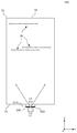
Classifications
-
- G—PHYSICS
- G02—OPTICS
- G02B—OPTICAL ELEMENTS, SYSTEMS OR APPARATUS
- G02B3/00—Simple or compound lenses
-
- G—PHYSICS
- G02—OPTICS
- G02B—OPTICAL ELEMENTS, SYSTEMS OR APPARATUS
- G02B3/00—Simple or compound lenses
- G02B3/02—Simple or compound lenses with non-spherical faces
- G02B3/08—Simple or compound lenses with non-spherical faces with discontinuous faces, e.g. Fresnel lens
-
- G—PHYSICS
- G02—OPTICS
- G02B—OPTICAL ELEMENTS, SYSTEMS OR APPARATUS
- G02B5/00—Optical elements other than lenses
- G02B5/18—Diffraction gratings
-
- G—PHYSICS
- G02—OPTICS
- G02B—OPTICAL ELEMENTS, SYSTEMS OR APPARATUS
- G02B6/00—Light guides; Structural details of arrangements comprising light guides and other optical elements, e.g. couplings
- G02B6/10—Light guides; Structural details of arrangements comprising light guides and other optical elements, e.g. couplings of the optical waveguide type
- G02B6/12—Light guides; Structural details of arrangements comprising light guides and other optical elements, e.g. couplings of the optical waveguide type of the integrated circuit kind
- G02B6/122—Basic optical elements, e.g. light-guiding paths
-
- G—PHYSICS
- G03—PHOTOGRAPHY; CINEMATOGRAPHY; ANALOGOUS TECHNIQUES USING WAVES OTHER THAN OPTICAL WAVES; ELECTROGRAPHY; HOLOGRAPHY
- G03B—APPARATUS OR ARRANGEMENTS FOR TAKING PHOTOGRAPHS OR FOR PROJECTING OR VIEWING THEM; APPARATUS OR ARRANGEMENTS EMPLOYING ANALOGOUS TECHNIQUES USING WAVES OTHER THAN OPTICAL WAVES; ACCESSORIES THEREFOR
- G03B35/00—Stereoscopic photography
- G03B35/18—Stereoscopic photography by simultaneous viewing
- G03B35/24—Stereoscopic photography by simultaneous viewing using apertured or refractive resolving means on screens or between screen and eye
Definitions
- the present invention relates to an optical device.
- Patent Document 1 JP 2012-008464 A
- the optical device includes a light conversion unit that converts light from the light source, and a light guide plate that guides light from the light source converted by the light conversion unit in a plane parallel to the emission surface. And a deflection unit that forms an image by deflecting the light guided by the light guide plate and emitting it from the exit surface, and the light conversion unit transmits the light emitted from the light source in a plane parallel to the exit surface. By condensing or diverging, it is converted into light emitted from a smaller region, and the deflecting unit forms different images depending on the viewing direction.
- the deflecting unit receives light guided by the light guide plate and substantially converges to one convergence point or convergence line in space or substantially diverges from one convergence point or convergence line in space.
- the light conversion unit may have an opening that restricts the passage of light emitted from the light emission port of the light source in a direction perpendicular to the light guide direction of the light guide plate and parallel to the emission surface.
- the light conversion unit may include a light conversion element that focuses or diverges light from the light source in a plane parallel to the emission surface.
- a light source may be further provided.
- the optical device includes a laser light source, a light guide plate that guides light from the laser light source in a plane parallel to the emission surface, and deflects light guided by the light guide plate. And a deflecting unit that forms different images depending on the observation direction by emitting the light from the emission surface.
- the deflecting unit receives light guided by the light guide plate and substantially converges to one convergence point or convergence line in space or substantially diverges from one convergence point or convergence line in space.
- the light guide plate further includes a light conversion unit that focuses light from the light source in a plane parallel to the emission surface, and the light guide plate receives light that has exited from the laser light source and passed through the light conversion unit. You may guide in a parallel plane.
- a light diffusing unit that diffuses light incident on the light guide plate in a plane parallel to the exit surface may be further provided.
- a light diffusing portion that diffuses light incident on the light guide plate in a plane perpendicular to the exit surface and along the light guide direction of the light guide plate may be further provided.
- a light divergence part that diverges light incident on the light guide plate in a plane perpendicular to the light exit surface and along the light guide direction of the light guide plate and exits to the diffusion part may be further provided.
- a light divergence portion that spreads light incident on the light guide plate in a plane perpendicular to the light exit surface and along the light guide direction of the light guide plate, and light spread by the light divergence portion is perpendicular to the light exit surface and guided by the light guide plate.
- a light collimating unit that collimates in a plane along the direction and enters the light guide plate may be further included.
- a reflection film may be further provided that is provided on a surface opposite to the emission surface and reflects the wavelength of light from the laser light source and transmits light in other wavelength regions.
- the deflection unit may be formed of a diffraction grating.
- the deflection unit may have a cylindrical reflection surface that reflects light guided by the light guide plate.
- Each of the light converging portions of the plurality of light converging portions includes a reflecting surface that emits outgoing light in a direction that substantially converges to one converging point in space or substantially diverges from one converging point in space.
- a plurality of light guide plates may be provided at different positions along the light guide direction of the light guide plate.
- a plurality of reflective surfaces at different positions along the light guide direction of the light guide plate may form a Fresnel lens.
- the deflection unit may form a binocular or multi-view parallax image on the light guide plate.
- the display apparatus 10 in one Embodiment is shown schematically with the three-dimensional image projected on space.
- An xy section of display 10 is shown roughly.
- 1 schematically shows a yz section of a display device 10.
- the yz cross section of 10 A of display apparatuses as a modification of the display apparatus 10 is shown roughly.
- a yz section of display 10B as a modification of display 10A is shown roughly.
- the yz cross section of 10 C of display apparatuses as a modification of the display apparatus 10 is shown roughly.
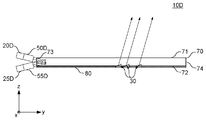
- a yz section of display 10D as a modification of display 10C is shown roughly.
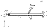
- the yz cross section of the display apparatus 10E as a modification of the display apparatus 10 is shown roughly.
- FIG. 3 is a schematic perspective view showing the light source 20 and the incident light adjusting unit 50 in an exploded manner.
- An xy section of display 10F as a modification of display 10 is shown roughly.
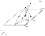
- the yz cross section of the display apparatus 10G as a modification of the display apparatus 10 is shown roughly.
- a perspective view of display device 10G is shown roughly with a part of incident light and outgoing light.
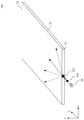
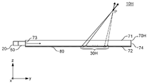
- the yz cross section of the display apparatus 10H as a modification of the display apparatus 10 is shown schematically.
- a perspective view of display 10H is shown roughly with a part of incident light and outgoing light.
- a yz section of display 10I as a modification of display 10C is shown roughly.
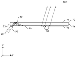
- the yz section of display 10J as a modification of display 10 is shown roughly.
- An xy section of display 10K as a modification of display 10 is shown roughly. It is a figure explaining the divergence angle of the geometrical light in the surface parallel to the output surface 71.
- FIG. An xy section of display 10L as a modification of display 10K is shown roughly.
- An xy section of display 10M as a modification of display 10K is shown roughly.
- An xy section of display 10N as a modification of display 10M is shown roughly.
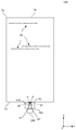
- An xy section of display 10O as a modification of display 10K is shown roughly.
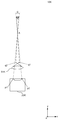
- FIG. 1 schematically shows a display device 10 according to an embodiment together with a stereoscopic image projected onto a space.
- the figure used for description of embodiment shall be schematic or typical for the purpose of explaining in an easy-to-understand manner.
- the figure used for description of the embodiment may not be drawn on an actual scale.
- the display device 10 has an emission surface 71 that emits light.
- the display device 10 forms an image 6 as a three-dimensional image with light emitted from the emission surface 71.
- the image 6 is a stereoscopic image that is recognized in space by the user.
- the three-dimensional image refers to an image that is recognized as being at a position different from the emission surface 71 of the display device 10.
- the three-dimensional image includes, for example, a two-dimensional image recognized at a position away from the emission surface 71 of the display device 10. That is, the stereoscopic image is a concept including not only an image recognized as a stereoscopic shape but also an image having a two-dimensional shape recognized at a position different from the display surface of the display device 10.
- the display device 10 includes a light guide plate 70, a light source 20, and an incident light adjusting unit 50.
- the light guide plate 70 is formed of a resin material that is transparent and has a relatively high refractive index.
- the material forming the light guide plate 70 may be, for example, polycarbonate resin (PC), polymethyl methacrylate resin (PMMA), glass, or the like.
- the light guide plate 70 has a back surface 72 opposite to the exit surface 71.
- the light guide plate 70 includes an end surface 73, an end surface 74, an end surface 75, and an end surface 76 that are the four end surfaces of the light guide plate 70.
- the end surface 73 is a light incident end surface of the light guide plate 70.
- the light source 20 is provided on the end surface 73, and light from the light source 20 enters the light guide plate 70 from the end surface 73.
- the end surface 74 is a surface opposite to the end surface 73.
- the end surface 76 is a surface opposite to the end surface 75.
- the light guide plate 70 guides light from the light source 20 by spreading it in a plane in a plane parallel to the emission surface 71.
- a right-handed orthogonal coordinate system of the x axis, the y axis, and the z axis may be used.
- the z-axis direction is determined in a direction perpendicular to the emission surface 71.
- the direction from the back surface 72 to the emission surface 71 is defined as the z-axis plus direction.
- the y-axis direction is determined in a direction perpendicular to the end face 73.
- the direction from the end surface 73 to the end surface 74 is defined as the y-axis plus direction.
- the x-axis is a direction perpendicular to the end face 75 and the end face 76, and the direction from the end face 75 to the end face 76 is defined as the x-axis plus direction.
- a plane parallel to the xy plane may be called an xy plane
- a plane parallel to the yz plane may be called a yz plane
- a plane parallel to the xz plane may be called an xz plane.
- the light source 20 is a laser light source.
- the light source 20 has a laser diode, for example.
- the light source 20 is, for example, monochromatic coherent light in a narrow wavelength region.
- the optical axis of the light source 20 is substantially parallel to the y-axis direction. Light from the light source 20 is adjusted by the incident light adjusting unit 50 and enters the end surface 73 as incident light to the light guide plate 70.
- a plurality of light converging portions 30 including a light converging portion 30a, a light converging portion 30b, and a light converging portion 30c are formed on the back surface 72 of the light guide plate 70.
- the light converging unit 30 is an example of a deflecting unit that forms an image by deflecting the light guided by the light guide plate 70 and emitting it from the exit surface 71.
- the light converging part 30 is formed substantially continuously in the x-axis direction. Light guided by the light guide plate 70 is incident on each position of the light converging unit 30 in the x-axis direction.
- FIG. 1 particularly shows a light converging unit 30a, a light converging unit 30b, and a light converging unit 30c as a part of the light converging unit 30, and in each of the light converging unit 30a, the light converging unit 30b, and the light converging unit 30c.
- a state in which a plurality of light beams emitted from the light converging unit 30a, the light converging unit 30b, and the light converging unit 30c converge is shown.
- the light converging unit 30 a corresponds to the fixed point PA on the image 6. Light rays from each position of the light converging unit 30a converge to a fixed point PA. Therefore, the wavefront of the light from the light converging unit 30a becomes a wavefront of light emitted from the fixed point PA.
- the light converging unit 30 b corresponds to the fixed point PB on the image 6. Light rays from each position from the light converging unit 30b converge to the fixed point PB. As described above, the light beam from each position of the arbitrary light converging unit 30 substantially converges to a fixed point corresponding to the light converging unit 30.
- a wavefront of light that emits light from a corresponding fixed point can be provided by an arbitrary light converging unit 30.
- the fixed points corresponding to each light converging unit 30 are different from each other, and an image 6 recognized in space is formed by a collection of a plurality of fixed points respectively corresponding to the light converging units 30.
- the display device 10 projects a stereoscopic image on the space.
- the human eye can see light emitted from different positions of the light converging unit 30 depending on the viewing direction. Therefore, different images can be seen on the light guide plate 70 depending on the viewing direction.
- each of the light converging portions 30 includes a large number of reflecting surfaces formed substantially continuously in the x-axis direction.
- the reflected light of the reflecting surface of each arbitrary light converging unit 30 converges to a fixed point corresponding to the light converging unit 30.
- the light beams of the plurality of reflected lights from the plurality of reflecting surfaces included in the light converging unit 30a converge on the fixed point PA.
- the light beams of the plurality of reflected lights from the plurality of reflecting surfaces of the light converging unit 30b converge at the fixed point PB.
- the light beams of the plurality of reflected lights from the plurality of reflecting surfaces of the light converging unit 30c converge on the fixed point PC.
- the light beam guided by the light guide plate 70 and passing through each position in the light guide plate 70 has a spread angle smaller than a predetermined value around the direction connecting each position in the light guide plate 70 and the light source 20.
- the light beam passing through each position in the light guide plate 70 has a spread angle smaller than a predetermined value around the direction connecting each position in the light guide plate 70 and the light source 20 in the xy plane.
- a light beam that is guided by the light guide plate 70 and passes through each position in the light guide plate 70 in a plane that includes a line connecting each position in the light guide plate 70 and the light source 20 and that is orthogonal to the xy plane is transmitted through the light guide plate 70.
- the light converging unit 30 When the light converging unit 30 is provided at a position away from the light source 20, the light beam guided by the light guide plate 70 and incident on the light converging unit 30 has a small spread around the y-axis direction. Therefore, for example, on a plane that includes the fixed point PA and is parallel to the xz plane, the light from the light converging unit 30a substantially converges to one fixed point.
- the spread of the light beam refers to the spread of light when the light beam passing through the point inside and outside the light guide plate is regarded as the light beam diverging from that point.
- the spread of the light beam may be simply referred to as the spread of light.
- the light spread angle may be a width (full width at half maximum) at a position where the light intensity is half of the maximum value in the light intensity distribution in the angular direction at the points inside and outside the light guide plate.
- the light converging part 30a is formed along the line 190a.
- the light converging part 30b is formed along the line 190b.
- the light converging part 30c is formed along the line 190c.
- the line 190a, the line 190b, and the line 190c are straight lines substantially parallel to the x-axis.
- the arbitrary light converging part 30 is formed substantially continuously along a straight line substantially parallel to the x-axis.
- the light converging part 30 is formed along a predetermined line in a plane parallel to the emission surface 71. Then, each of the light converging units 30 causes the light guided by the light guide plate 70 to enter, and emit the emitted light in a direction substantially converging to one convergence point in space from the emission surface 71.
- the emitted light is light in a direction diverging from the fixed point. Therefore, when the fixed point is on the rear surface 72 side of the light guide plate 70, the reflection surface of the light converging unit 30 causes the emission surface 71 to emit the emitted light in a direction substantially diverging from one convergence point in space.
- the light from the light converging unit 30 substantially converges to a fixed point as described above.
- the light guided by the light guide plate 70 has a spread in the direction along the yz plane
- the light reflected by the reflection surface of the light converging unit 30 is substantially on a convergence line parallel to the yz plane and parallel to the exit surface.
- Converge For example, light from the light converging unit 30a includes PA, and substantially converges on a line parallel to the yz plane and parallel to the exit surface.
- the reflection surface of the light converging unit 30 causes the emission surface 71 to emit emission light in a direction substantially diverging from one convergence line in space.
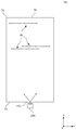
- FIG. 2 schematically shows an xy section of the display device 10.
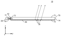
- FIG. 3 schematically shows a yz section of the display device 10.
- the incident light adjusting unit 50 includes an optical element 51 and an optical element 52.
- the optical element 51 and the optical element 52 are provided in the order of the optical element 51 and the optical element 52 along the optical axis of the light source 20 in the direction in which the light from the light source 20 travels.
- the optical element 52 is provided on the end face 73
- the optical element 51 is provided between the optical element 52 and the light source 20.
- the light from the light source 20 passes through the optical element 51 and the optical element 52 in order, and enters the end surface 73 of the light guide plate 70.
- the optical element 51 is an example of a light conversion unit that converts light from the light source 20.
- the optical element 51 converts light emitted from the light source 20 into light emitted from a smaller region by condensing or diverging light in a plane parallel to the emission surface 71. Specifically, the optical element 51 focuses the light from the light source 20 in a plane parallel to the emission surface 71.
- the optical element 51 converts the light from the light source 20 into light having a smaller spread angle of light in a plane parallel to the emission surface 71, and travels to the light guide plate 70 along the light guide direction of the light guide plate 70. Exit toward.
- the optical element 51 is a lens having a positive power in a plane parallel to the emission surface 71.
- the optical element 51 is a condensing lens and substantially condenses the light flux from one point. Specifically, the optical element 51 condenses the light flux from one point in a plane parallel to the emission surface 71. The optical element 51 condenses light from each point of the light emission port of the laser light source 20 in a plane parallel to the emission surface 71.
- the optical element 51 condenses the light beam emitted from the center of the light exit of the light source 20 at the position of the optical element 52 or a position near the optical element 52.
- the light beam from each point of the light exit of the light source 20 is collected by the optical element 51 at the position of the optical element 52 or a position near the optical element 52 in the direction along the y-axis.
- the optical element 51 provides a pseudo light source smaller than the light source 20.
- the spread angle of the light guided by the light guide plate 70 becomes smaller than a predetermined value in the plane parallel to the emission surface 71.
- the optical element 52 spreads the incident light in a plane parallel to the emission surface 71. Specifically, the optical element 52 spreads the incident light in a plane parallel to the emission surface 71 by diffusing the incident light.
- the optical element 52 is an example of a light diffusion unit that diffuses light incident on the light guide plate 70 in a plane parallel to the emission surface 71.
- the incident light adjusting unit 50 the light from the light source 20 is focused at the position of the optical element 52, and the light incident on the optical element 52 becomes a light beam having a relatively small diameter. Then, the light from the light source 20 is spread in the xy plane by the optical element 52. Therefore, when projected onto the xy plane, the light incident on the light guide plate 70 can be made closer to the light that spreads out from the point light source, compared to the case where the incident light adjustment unit 50 does not exist. Thereby, the spread angle of light at each point in the light guide plate 70 can be reduced in the xy plane. Therefore, the spread of the light reflected by each reflecting surface of the light converging unit 30 can be reduced. Therefore, the blur of the image 6 can be reduced.
- a reflective film 80 is provided on the back surface 72 of the light guide plate 70.
- the reflective film 80 substantially reflects the wavelength of light from the light source 20, and substantially transmits light in other wavelength ranges.
- the reflective film 80 substantially transmits light in a wavelength range belonging to visible light excluding the wavelength range of light from the light source 20. Thereby, it can suppress that the light from the light source 20 leaks outside in the middle of propagating the light guide plate 70. Further, it is possible to provide the display device 100 that is transparent when viewed from the observer.
- the optical element 52 may be realized by an uneven pattern that spreads incident light in the xy plane.
- the optical element 52 may be a concavo-convex pattern in which convex portions and concave portions extending in the z-axis direction appear alternately in the direction along the x-axis direction.
- the optical element 52 may be formed as a part of the end surface 73 instead of a member different from the light guide plate 70.
- a form without the optical element 52 may be adopted.
- the optical element 51 may be a lens having negative power. In this case, the focal point of the optical element 51 may be at the position of the end face 73 or in the vicinity of the end face 73.
- a form without the incident light adjustment unit 50 may be adopted.
- a divergent light source may be used instead of the light source 20, and light obtained by substantially collimating the light from the divergent light source with an optical element such as a lens may be applied as incident light to the incident light adjusting unit 50. .
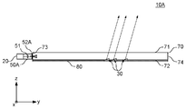
- FIG. 4 schematically shows a yz section of a display device 10 ⁇ / b> A as a modification of the display device 10.
- the display device 10A includes an incident light adjustment unit 50A corresponding to the incident light adjustment unit 50, and is substantially the same as the display device 10 except that the characteristics of the optical element 52A included in the incident light adjustment unit 50A are different from those of the optical element 52.
- the optical element 52A spreads the incident light within a plane perpendicular to the emission surface 71 and along the light guide direction of the light guide plate 70. Specifically, the optical element 52A spreads the incident light in the yz plane by diffusing the incident light.
- the optical element 52 ⁇ / b> A is an example of a light diffusing unit that diffuses light traveling toward the light guide plate 70 in a plane perpendicular to the emission surface 71 and along the light guide direction of the light guide plate 70.
- This figure shows a state in which a light beam in a direction along the optical axis of the light source 20 is incident on the optical element 52A.
- the light from the light source 20 is diffused in the yz plane by the optical element 52 ⁇ / b> A and enters the light guide plate 70. Therefore, as compared with the display device 10, the incident light on the light guide plate 70 enters the end surface 73 at various angles. Therefore, as compared with the display device 10, the part where the light propagating in the light guide plate 70 is reflected by the back surface 72 is less likely to concentrate on a specific part. Therefore, as compared with the display device 10, it is possible to make it difficult to cause unevenness in the amount of light in a plane parallel to the emission surface 71.
- the optical element 52A may be a concavo-convex pattern in which convex portions and concave portions extending in the x-axis direction appear alternately in the direction along the z-axis direction.
- the optical element 52 ⁇ / b> A may be formed as a part of the end surface 73 instead of a member different from the light guide plate 70.
- the optical element 52A may have a characteristic of spreading light in the xy plane in addition to a characteristic of spreading light in the yz plane.
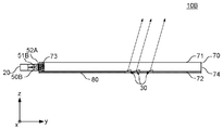
- FIG. 5 schematically shows a yz section of a display device 10B as a modification of the display device 10A.
- the display device 10B includes an incident light adjustment unit 50B corresponding to the incident light adjustment unit 50, except that the characteristics of the optical element 51B included in the incident light adjustment unit 50B are different from the characteristics of the optical element 51. It has almost the same configuration.
- the optical element 51 ⁇ / b> B spreads the incident light in a plane perpendicular to the emission surface 71 and along the light guide direction of the light guide plate 70. Specifically, the optical element 51B spreads in the yz plane by diverging the incident light.
- the optical element 51 ⁇ / b> B is an example of a light divergence unit that diverges incident light within a plane perpendicular to the emission surface 71 and along the light guide direction of the light guide plate 70.
- the optical element 51B is a diverging lens having negative power, for example.
- the optical element 51B spreads the incident light in the yz plane and enters the optical element 52A.
- the optical element 51B does not substantially diverge incident light in the xy plane.
- This figure shows a state in which three light beams from the light source 20 are incident on the optical element 51B.
- the light from the light source 20 is diverged in the yz plane by the optical element 51A and enters the optical element 52A.
- the light diffused by the optical element 52 ⁇ / b> A enters the light guide plate 70. Therefore, as compared with the display device 10A, the incident light to the light guide plate 70 enters the end surface 73 from various positions in the z direction at various angles. Therefore, compared with the display device 10A, the portion where the light propagating in the light guide plate 70 is reflected by the back surface 72 can be more dispersed in the y-axis direction.
- the optical element 52 ⁇ / b> A may be formed as a part of the end surface 73 instead of a member different from the light guide plate 70.
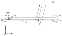
- FIG. 6 schematically shows a yz section of a display device 10 ⁇ / b> C as a modification of the display device 10.
- the display device 10 ⁇ / b> C includes an incident light adjusting unit 50 ⁇ / b> C corresponding to the incident light adjusting unit 50, and the characteristics of the optical element 51 ⁇ / b> C included in the incident light adjusting unit 50 ⁇ / b> C are different from the characteristics of the optical element 51.
- the display device 10 has substantially the same configuration except that the characteristics of the optical element 52C are different from those of the optical element 52. Since the optical element 51C has the same characteristics as the optical element 51B, description thereof is omitted.
- the optical element 52C collimates the light spread by the optical element 51C in a plane perpendicular to the emission surface 71 and along the light guide direction of the light guide plate 70, and enters the light guide plate 70.
- the optical element 52C is a lens having positive power, for example.
- the optical element 52C is an example of a light collimating unit.
- the optical element 51C may completely collimate the incident light, or may substantially collimate the incident light. Further, the optical element 52C may collimate the incident light so that the light has a divergence angle smaller than that of the light emitted from the light source 20.
- the optical element 52C does not collimate incident light in the xy plane.
- each of the light converging units 30 of the light guide plate 70 can emit light from the light guide plate 70 so as to substantially converge at a corresponding convergence point.
- FIG. 7 schematically shows a yz section of a display device 10D as a modification of the display device 10C.
- the display device 10C has substantially the same configuration as the display device 10 except that the display device 10C includes a plurality of light sources and incident light adjustment units.
- the display device 10D includes a light source 20D and an incident light adjustment unit 50D instead of the light source 20 and the incident light adjustment unit 50C of the display device 10C.
- the display device 10D further includes a light source 25D and an incident light adjustment unit 55D.
- the light source 20D and the light source 25D have the same functions as the light source 20.
- the direction of the light source 20D is different from that of the light source 25D.
- the direction of the optical axis of the light source 20D is different from the direction of the optical axis of the light source 25D.
- the optical axis of the light source 20D and the optical axis of the light source 25D are in the same plane parallel to the yz plane, but the direction of the optical axis of the light source 20D is different from the direction of the optical axis of the light source 25D.
- the minimum angle formed between the optical axis of the light source 20D and the end surface 73 is substantially the same as the minimum angle formed between the optical axis of the light source 25D and the end surface 73.
- the incident light adjusting unit 50D is provided so that the central axis of the optical element included in the incident light adjusting unit 50D substantially coincides with the optical axis of the light source 20D.
- the incident light adjusting unit 55D is provided such that the central axis of the optical element included in the incident light adjusting unit 55D substantially coincides with the optical axis of the light source 25D.
- the display device 10D includes two sets of light sources and incident light adjustment units having different optical axes, but may include three or more sets of light sources and incident light adjustment units having different optical axes.
- FIG. 8 schematically shows a yz section of a display device 10E as a modification of the display device 10.
- the display device 10A includes an incident light adjustment unit 50E corresponding to the incident light adjustment unit 50.
- the optical element 51E included in the incident light adjustment unit 50E is different from the optical element 51, and the optical element 52E included in the incident light adjustment unit 50E.
- the display device 10 has substantially the same configuration except that the characteristics are different from those of the optical element 52.
- the incident light adjusting unit 50E diffuses light from the light source 20 in at least one of a plane parallel to the emission surface and a plane perpendicular to the emission surface and along the light guide direction of the light guide plate. The light enters the light guide plate along the light guide direction.
- the incident light adjusting unit 50E includes an optical element 51E and an optical element 52E.
- FIG. 9 is a schematic perspective view showing the light source 20 and the incident light adjusting unit 50 in an exploded manner.
- the incident light adjusting unit 50E spreads the light from the light source 20 in both a plane parallel to the emission surface 71 and a plane perpendicular to the emission surface 71 and along the light guide direction of the light guide plate 70.
- the light enters the light guide plate 70 along the light guide direction of the light guide plate 70.
- the optical element 51 ⁇ / b> E diffuses light in a direction along the light guide direction of the light guide plate 70 in a plane perpendicular to the emission surface 71 and along the light guide direction of the light guide plate 70.
- the optical element 52 ⁇ / b> E spreads the light spread by the optical element 51 ⁇ / b> E in a plane parallel to the emission surface 71 and enters the light guide plate 70.
- the optical element 52E spreads in the xy plane as well as in the yz plane by diffusing the light spread in the yz plane by the optical element 51E.
- the light beam that is incident from the end face 73 and propagates through the light guide plate 70 is substantially a light beam that travels while spreading from the point light source in the xy plane.
- the light beam that enters from the end surface 73 and propagates through the light guide plate 70 travels while reflecting between the exit surface 71 and the back surface 72 at various angles. Therefore, the light from one light converging unit 30 travels in various directions within the yz plane.
- the light beam is such that light emitted from the point light source substantially travels, so that the convergence point or the convergence point does not greatly shift in the xy plane. Therefore, the observer can recognize the stereoscopic image 6 from various directions.
- the light from the light source 20 that is laser light is diffused by the optical element 51E, and then diffused again by the optical element 52E at different positions in the z direction. Therefore, laser speckle can be suppressed.
- the laser speckle may be suppressed by vibrating the light source 20 in a direction parallel to the z-axis direction.
- a configuration in which the optical element 52E does not have a function of spreading light in the yz plane may be adopted.
- a configuration in which the optical element 52E does not have a function of spreading light in the xy plane may be adopted.
- the optical element 52 ⁇ / b> E may be formed as a part of the end surface 73 instead of a member different from the light guide plate 70.
- FIG. 10 schematically shows an xy cross section of a display device 10F as a modification of the display device 10.
- the display device 10A has substantially the same configuration as the display device 10 except that the configuration of the light converging unit 30F included in the light guide plate 70F is different from that of the light converging unit 30.
- the light converging unit 30F is a diffraction grating.
- the light converging unit 30 ⁇ / b> F causes light in a predetermined direction to be emitted from the emission surface 71 by diffracting light propagating through the light guide plate 70.
- the light source 20 is a laser light source, and the light from the light source 20 is substantially a single wavelength coherent light. Therefore, even if a diffraction grating is used for the light converging unit 30, it is possible to suppress the variation of the direction of the emitted light.
- the length of the light converging unit 30 in the y direction can be shortened compared to the case of using a reflecting surface. Therefore, a stereoscopic image can be projected at a fine convergence point or convergence line.
- the pattern pitch of the diffraction grating can be reduced, the resolution of the stereoscopic image can be increased.
- the length of the light converging part 30 in the y direction can be shortened, the light guide plate 70 can be made more transparent.
- the display device 10 ⁇ / b> F has the incident light adjustment unit 50.
- the incident light adjusting unit 50 may not include the optical element 51.
- the incident light adjusting unit 50 may not include the optical element 51, and the optical element 52 may spread light in the xy plane, but may not employ light in the yz plane.
- FIG. 11 schematically shows a yz section of a display device 10G as a modification of the display device 10.
- FIG. 12 schematically shows a perspective view of the light guide plate 70G together with a part of incident light and outgoing light.
- the display device 10G has a light converging unit 30G having a cylindrical reflecting surface instead of the light converging unit 30.
- the light converging part 30G has a cylindrical shape extending along the x-axis direction.
- the display device 10G has substantially the same configuration as the display device 10 except for this point.
- the light propagating in the light guide plate 70 does not have various directional components in the yz plane.
- the light converging unit 30G has a cylindrical shape, the light is incident on the light converging unit 30G. Accordingly, outgoing light in different directions is generated in the yz plane. Thereby, the direction which can provide a three-dimensional image can be increased, without providing the spreading
- the spread of the emitted light in the yz plane depends on the spread in the yz plane in the light guide plate 70. Therefore, if the spread in the yz plane of the light propagating in the light guide plate 70 is increased in order to provide the emitted light from the light guide plate 70 in a wide range in the yz plane, the spread of the emitted light from the light guide plate 70 is also one. May become larger. On the other hand, in the display device 10G, the spread of the light emitted from the light guide plate 70 is determined by a cylindrical curved surface.
- FIG. 13 schematically shows a yz section of a display device 10H as a modification of the display device 10.
- FIG. 14 schematically shows a perspective view of the light guide plate 70H together with a part of incident light and outgoing light.
- the display device 10H has a light converging unit 30H instead of the light converging unit 30.
- the light converging unit 30H has the shape of a Fresnel lens that emits light that converges at a fixed point P.
- the display device 10H has substantially the same configuration as the display device 10 except for this point.
- the plurality of reflecting surfaces included in one light converging unit 30H form a reflecting surface of one Fresnel lens corresponding to one fixed point P.
- the outgoing light from the light converging unit 30H substantially converges to the fixed point P.
- light generated in various directions from the point P can be provided instead of light generated from a line. Therefore, a more complete stereoscopic image can be provided.
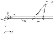
- FIG. 15 schematically shows a yz section of a display device 10I as a modification of the display device 10H.
- the display device 10I includes an incident light adjusting unit 50I instead of the incident light adjusting unit 50C. Except for this point, the display device 10I has substantially the same configuration as the display device 10H.
- the incident light adjusting unit 50I includes an optical element 52I corresponding to the optical element 52H.
- the optical element 52I not only spreads the incident light in the xy plane but also spreads the light in the yz plane in the same manner as the optical element 52C.
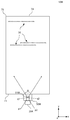
- the amount of light spread in the yz plane by the optical element 52I is limited to a predetermined amount.
- the amount of light spread in the yz plane by the optical element 52I is limited to such a spread that the light beams from the light converging unit 30H corresponding to different fixed points can be separated in the y-axis direction. Thereby, it can suppress that a stereo image can be provided only to a specific direction.
- FIG. 16 schematically shows a yz section of a display device 10J as a modification of the display device 10.
- the display device 10 ⁇ / b> J light enters the light guide plate 70 not from the end surface 73 but from the back surface 72. Further, the exit surface 71 of the light guide plate 70 has a deflection optical surface 40.
- the display device 10H has substantially the same configuration as the display device 10 except for these points.
- the deflection optical surface 40 deflects light incident on the light guide plate 70 from the back surface 72 in the light guide direction of the light guide plate 70.
- the deflecting optical surface 40 is, for example, a diffraction grating, and deflects light incident on the light guide plate 70 from the back surface 72 in the light guide direction of the light guide plate 70.
- FIG. 1 a form in which the light source 20 and the incident light adjusting unit 50 are provided on the emission surface 71 side and the surface on which light enters the light guide plate 70 is the emission surface 71 may be adopted.
- the deflection optical surface may be provided on the back surface 72 or on the exit surface 71.
- the wavelength range of the light from the light source 20 belongs to a monochromatic narrow band wavelength range.
- the light source 20 may be a laser light source that emits laser beams of a plurality of colors.
- the light source 20 may be a laser light source that emits laser beams of three different colors.
- the light source 20 may mix the laser light from each laser light source and emit it from one light emission port.
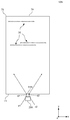
- FIG. 17 schematically shows an xy section of a display device 10K as a modification of the display device 10.
- the display device 10 ⁇ / b> K includes a light source 20 ⁇ / b> K instead of the light source 20, and includes an incident light adjustment unit 50 ⁇ / b> K instead of the incident light adjustment unit 50. Except for this point, the display device 10 ⁇ / b> K has substantially the same configuration as the display device 10.
- the light source 20K is a divergent light source.
- the light source 20K may be, for example, an LED.
- the light source 20K emits diverging light from each point of the light exit.
- the incident light adjusting unit 50 ⁇ / b> K includes an optical element 51 ⁇ / b> K corresponding to the optical element 51.
- the optical element 51K condenses the light emitted from the light source 20K in the xy plane.
- the optical element 51K condenses the light from each point of the exit of the light source 20K at the position of the optical element 52 or a position near the optical element 52.
- the condensing characteristic of the optical element 51K may be different from the condensing characteristic of the optical element 51.
- the optical element 51K has such a power that the size of the image of the light exit of the light source 20K formed at the position of the optical element 52 is smaller than the size of the light exit of the light source 20K.
- the light beam from one end point p1 in the x-axis direction of the light exit of the light source 20K is condensed at the point q1 at the position of the optical element 52.
- the light beam from the other end point p2 in the x-axis direction of the light exit of the light source 20K is condensed at the point q2 at the position of the optical element 52.
- the optical element 51K converts the light from the light source 20 into light having a smaller light spread angle in a plane parallel to the emission surface 71, and guides the light guide plate along the light guide direction of the light guide plate 70.
- the light is emitted toward 70. Therefore, the light incident on the light guide plate 70 can be made closer to the light from the point light source as compared with the case where the incident light adjusting unit 50K is not present.
- FIG. 18 is a diagram for geometrically explaining the spread angle of light in a plane parallel to the emission surface 71.
- the point A can represent an arbitrary point in the light guide plate 70.
- the light divergence angle is the maximum angle of the light beam formed by the light beam passing through the point A.
- the angle ⁇ is an angle formed by a line connecting the end point p1 of the light exit port and the point A and a line connecting the end point p2 of the light exit port and the point A.
- the optical element 51K When the optical element 51K exists, the light passing through the point A substantially passes through the range of the angle ⁇ .
- the angle ⁇ is an angle formed by a line connecting the end point q1 and the point A and a line connecting the end point q2 and the point A.
- the presence of the optical element 51 converts the light from the light source 20 into light having a smaller light spread angle in a plane parallel to the emission surface 71. Therefore, the spread angle of the light reflected by the light converging unit 30 is also reduced. Therefore, the blur of the stereoscopic image can be reduced as compared with the case where the optical element 51K does not exist. Therefore, an image with high resolution can be provided by using a divergent light source such as an LED.
- the light spread angle is determined in relation to the light output port of the light source without considering the light intensity distribution in the light output port of the light source.
- the width full width at half maximum
- the width at the position where the light intensity becomes half of the maximum value in the light intensity distribution in the angular direction in the plane parallel to the emission surface 71 is used. Good.
- FIG. 19 schematically shows an xy section of a display device 10L as a modification of the display device 10K.
- the display device 10 ⁇ / b> L includes an optical element 51 ⁇ / b> L provided on the end surface 73 as an incident light adjusting unit, instead of the incident light adjusting unit 50 ⁇ / b> K.
- the optical element 51L is a portion protruding from the end face 73 in the negative y-axis direction. Similarly to the optical element 51K, the optical element 51L can also convert light from the light source 20 into light having a smaller light spread angle in a plane parallel to the emission surface 71. Therefore, the blur of the stereoscopic image can be reduced.
- FIG. 20 schematically shows an xy section of a display device 10M as a modification of the display device 10K.
- the display device 10M includes an incident light adjusting unit 50M corresponding to the incident light adjusting unit 50K. Except for this point, the display device 10M has substantially the same configuration as the display device 10K.
- the incident light adjusting unit 50M includes an optical element 51M corresponding to the optical element 51K.
- the optical element 51M has a negative power in a plane parallel to the emission surface 71.
- the optical element 51M diverges the light emitted from the light source 20K.
- a light beam from one end point p1 in the x-axis direction of the light exit of the light source 20K is diverged by the optical element 51M and converted into a light beam emitted from the point q1.
- the light beam from one end point p2 in the x-axis direction of the light exit of the light source 20K is diverged by the optical element 51M and converted into a light beam emitted from the point q2.
- the distance between the point q1 and the point q2 is shorter than the distance between the end point p1 and the end point p2.
- the width of the virtual image of the light exit of the light source 20K in the x-axis direction is reduced by the optical element 51M.
- the light from the light source 20 is also converted by the optical element 51M into light having a smaller light spread angle in a plane parallel to the emission surface 71, and is guided along the light guide direction of the light guide plate 70. Can be incident. Therefore, the blur of the stereoscopic image can be reduced. Further, since the angle ⁇ of the light beam incident on the light guide plate 70 can be increased, the light spreads quickly in the light guide plate 70. Therefore, the dead space of the light guide plate 70 can be reduced.
- FIG. 21 schematically shows an xy section of a display device 10N as a modification of the display device 10M.
- the display device 10 ⁇ / b> N includes an optical element 51 ⁇ / b> N provided on the end surface 73 as an incident light adjusting unit instead of the incident light adjusting unit 50 ⁇ / b> M.
- the optical element 51N is a portion that is recessed from the end surface 73 in the positive y-axis direction. Similarly to the optical element 51M, the optical element 51N can also convert light from the light source 20 into light having a smaller light spread angle in a plane parallel to the emission surface 71. Therefore, the blur of the stereoscopic image can be reduced.
- FIG. 22 schematically shows an xy cross section of a display device 10O as a modification of the display device 10K.
- the display device 10O includes an incident light adjusting unit 50O corresponding to the incident light adjusting unit 50K. Except for this point, the display device 10M has substantially the same configuration as the display device 10K.
- the incident light adjusting unit 50O includes an optical element 51O corresponding to the optical element 51K.
- the optical element 51O is a light shielding unit and has an opening that restricts passage of light emitted from the light emission port of the light source 20K in the x-axis direction.
- the center of the opening of the optical element 51O substantially coincides with the center of the light exit of the light source 20K.
- the light emission port of the light source 20K has a width L1 in the x-axis direction.
- the opening of the optical element 51O has a width L2 smaller than the width L1 in the x-axis direction.
- the optical element 51 ⁇ / b> O can convert the light from the light source 20 ⁇ / b> K into light having a smaller light spread angle in a plane parallel to the emission surface 71. Therefore, the blur of the stereoscopic image can be reduced.
- the light beam can be sampled in the traveling direction and the light beam emitted from the object can be reproduced.
- the convergence points can be provided with a small pitch, the resolution of the stereoscopic image can be increased.
- the reflected light becomes a light flux having a spread of about 1.7 mm in the xz plane at a position 10 cm away from the exit surface of the light guide plate in the z-axis direction.
- the spread of the light beam from one optical surface is smaller than this.
- the convergence points are set at a pitch of about 0.5 mm in order to obtain a desirable sampling density as a sampling point in space.
- the light spread angle is 1 °
- the diameter of the light flux is 0.52 mm at a position 30 mm from the emission surface 71. Therefore, in order to set the convergence point at a pitch of about 0.5 mm, the light spread angle is preferably less than 1 °.
- the convergence point when a predetermined value of 1 ° or more can be applied as the upper limit of the light spreading angle.
- the light spread angle may be less than 5 °.
- the convergence point When a point about 5 mm away from the exit surface of the light guide plate in the z-axis direction is set as the convergence point, the convergence point may be set at a pitch of 0.5 mm or less if the light spread angle is less than 5 °. it can.
- the pitch of sampling points in space can be made longer than 0.5 mm.
- a predetermined value of 1 ° or more can be applied as the upper limit of the light spread angle.
- various angles other than 1 ° and 5 ° described above can be applied as the predetermined upper limit value of the light spread angle.
- the light spread angle may be an angle when a light beam is projected onto the xy plane.
- the light spread angle may be an angle when a light beam is projected onto the yz plane.
- the light spread angle may be an angle when a light beam is projected onto a surface that includes a straight line connecting the position and the light source and is orthogonal to the exit surface of the light guide plate.
- the light source when a white LED is used, it is necessary to provide each color light-emitting chip in the light-emitting surface, so that the light emission port of the LED becomes large. If the width of the light exit port of the LED in the x-axis direction is 2 mm, a light spread angle of about 5.7 ° occurs at a point 20 mm away from the light incident end face of the light guide plate. Even at a point 50 mm away from the light incident end face of the light guide plate, a light spreading angle of about 2.3 ° occurs. In a region away from the light incident end surface, the light spread angle can be 1 ° or less.
- the display device 10 and various modifications related to the display device 10 can be modified to provide a binocular or multi-lens display device that provides a pseudo stereoscopic image with a parallax image.
- a binocular display device when a binocular display device is provided, a first reflecting surface group that forms a parallax image for the right eye on the light guide plate 70 and a first reflection surface group that forms a parallax image for the left eye on the light guide plate 70.
- parallax images for the right eye and the left eye may be provided.
- the twin-lens or multi-lens display device as a modification of the display device 10, it is possible to provide a parallax image by limiting the range of the viewpoint. For example, it is possible to provide a parallax image only to a person in a specific narrow area.
- Image 10 Display device 20 Light source 25 Light source 30 Light converging unit 40 Deflection optical surface 50 Incident light adjusting unit 51 Optical element 52 Optical element 55 Incident light adjusting unit 70 Light guide plate 71 Output surface 72 Rear surface 73 End surface 74 End surface 75 End surface 76 End surface 80 Reflective film 100 display device 190 lines
Landscapes
- Physics & Mathematics (AREA)
- General Physics & Mathematics (AREA)
- Optics & Photonics (AREA)
- Engineering & Computer Science (AREA)
- Microelectronics & Electronic Packaging (AREA)
- Planar Illumination Modules (AREA)
- Illuminated Signs And Luminous Advertising (AREA)
- Optical Elements Other Than Lenses (AREA)
- Optical Integrated Circuits (AREA)
- Diffracting Gratings Or Hologram Optical Elements (AREA)
Abstract
光デバイスは、光源からの光を変換する光変換部と、光変換部により変換された光源からの光を、出射面に平行な面内で導く導光板と、導光板によって導かれている光を偏向して出射面から出射させることで像を形成する偏向部とを備え、光変換部は、光源から発する光を、出射面に平行な面内で集光または発散させることで、より小さい領域から発する光に変換し、偏向部は、観察する方向によって異なる像を形成する。
Description
本発明は、光デバイスに関する。
導光板と、光源と、導光板の表面側に配置した、パララックスバリア方式又はレンズアレイ方式におけるマスク又はレンズアレイとを備えた、立体視可能な表示装置が知られている(例えば、特許文献1参照。)。
特許文献1 特開2012-008464号公報
特許文献1 特開2012-008464号公報
導光板内の出射面に平行な面内の各点における光の広がり角が大きいほど、導光板から出射する光の広がりが大きくなってしまう。そのため、特定の向きに限定した光を導光板から出射させることが容易でないという課題があった。例えば、2眼式や多眼式で視差画像を提供するシステムを導光板を用いて実現しようとすると、視点となる範囲を限定することができない。
本発明の第1の態様によると、光デバイスは、光源からの光を変換する光変換部と、光変換部により変換された光源からの光を、出射面に平行な面内で導く導光板と、導光板によって導かれている光を偏向して出射面から出射させることで像を形成する偏向部とを備え、光変換部は、光源から発する光を、出射面に平行な面内で集光または発散させることで、より小さい領域から発する光に変換し、偏向部は、観察する方向によって異なる像を形成する。
偏向部は、導光板によって導かれている光が入射し、空間上の1つの収束点又は収束線に実質的に収束する又は空間上の1つの収束点又は収束線から実質的に発散する方向の出射光を出射面から出射させる複数の光収束部を有し、複数の光収束部は、出射面に平行な面内でそれぞれ予め定められた線に沿って形成され、収束点又は収束線は複数の光収束部の間で互いに異なり、複数の収束点又は収束線の集まりによって空間上に像が形成されてよい。
光変換部は、導光板の導光方向に直交し出射面に平行な方向において、光源の光出射口から出射した光が通過することを制限する開口を有してよい。
光変換部は、出射面に平行な面内において光源からの光を集束又は発散する光変換素子を有してよい。
光源をさらに備えてよい。
本発明の第2の態様によると、光デバイスは、レーザ光源と、レーザ光源からの光を、出射面に平行な面内で導く導光板と、導光板によって導かれている光を偏向して出射面から出射させることで、観察する方向によって異なる像を形成する偏向部とを備える。
偏向部は、導光板によって導かれている光が入射し、空間上の1つの収束点又は収束線に実質的に収束する又は空間上の1つの収束点又は収束線から実質的に発散する方向の出射光を出射面から出射させる複数の光収束部を有し、複数の光収束部は、出射面に平行な面内でそれぞれ予め定められた線に沿って形成され、収束点又は収束線は複数の光収束部の間で互いに異なり、複数の収束点又は収束線の集まりによって空間上に像が形成されてよい。
出射面に平行な面内において光源からの光を集束する光変換部をさらに備え、導光板は、レーザ光源から出射して光変換部を通過した光が入射され、入射した光を出射面に平行な面内で導いてよい。
導光板に入射する光を、出射面に平行な面内で拡散する光拡散部をさらに備えてよい。
導光板に入射する光を、出射面に垂直かつ導光板の導光方向に沿う面内で拡散する拡散部をさらに備えてよい。
導光板に入射する光を、出射面に垂直かつ導光板の導光方向に沿う面内で発散して、拡散部に出射する光発散部をさらに備えてよい。
導光板に入射する光を、出射面に垂直かつ導光板の導光方向に沿う面内で広げる光発散部と、光発散部によって広げられた光を、出射面に垂直かつ導光板の導光方向に沿う面内で平行化して導光板に入射する光平行化部とをさらに備えてよい。
出射面とは反対側の面に設けられ、レーザ光源からの光の波長を反射し、他の波長域の光を透過する反射膜をさらに備えてよい。
偏向部は、回折格子で形成されてよい。
偏向部は、導光板によって導かれている光を反射するシリンドリカル形状の反射面を有してよい。
複数の光収束部のそれぞれの光収束部は、空間上の1つの収束点に実質的に収束する又は空間上の1つの収束点から実質的に発散する方向の出射光を出射する反射面を、導光板の導光方向に沿って互いに異なる位置に複数有してよい。
導光板の導光方向に沿って互いに異なる位置に複数有する反射面は、フレネルレンズを形成してよい。
偏向部は、二眼式又は多眼式の視差画像を導光板上に形成してよい。
なお、上記の発明の概要は、本発明の特徴の全てを列挙したものではない。また、これらの特徴群のサブコンビネーションもまた、発明となりうる。
以下、発明の実施の形態を通じて本発明を説明するが、以下の実施形態は請求の範囲にかかる発明を限定するものではない。また、実施形態の中で説明されている特徴の組み合わせの全てが発明の解決手段に必須であるとは限らない。
図1は、一実施形態における表示装置10を、空間上に投影される立体像と共に概略的に示す。なお、分かり易く説明することを目的として、実施形態の説明に用いる図は概略的又は模式的なものとする。実施形態の説明に用いる図は、実際のスケールで描かれていない場合がある。
表示装置10は、光を出射する出射面71を有する。表示装置10は、出射面71から出射する光によって、立体像としての像6を形成する。像6は、ユーザによって空間上に認識される立体像である。なお、立体像とは、表示装置10の出射面71とは異なる位置にあるように認識される像をいう。立体像とは、例えば、表示装置10の出射面71から離れた位置に認識される2次元像も含む。つまり、立体像とは、立体的な形状として認識される像だけでなく、表示装置10の表示面上とは異なる位置に認識される2次元的な形状の像も含む概念である。
表示装置10は、導光板70と、光源20と、入射光調節部50とを備える。導光板70は、透明で屈折率が比較的に高い樹脂材料で成形される。導光板70を形成する材料は、例えばポリカーボネート樹脂(PC)、ポリメチルメタクリレート樹脂(PMMA)、ガラス等であってよい。
導光板70は、出射面71とは反対側の背面72とを有する。また、導光板70は、導光板70の四方の端面である端面73、端面74、端面75及び端面76を有する。端面73は、導光板70の入光端面である。端面73には光源20が設けられ、光源20からの光は、端面73から導光板70に入射する。端面74は、端面73とは反対側の面である。端面76は、端面75とは反対側の面である。導光板70は、光源20からの光を出射面71に平行な面内で面状に広げて導く。
実施形態の説明において、x軸、y軸及びz軸の右手系の直交座標系を用いる場合がある。z軸方向を、出射面71に垂直な方向で定める。背面72から出射面71への向きをz軸プラス方向と定める。また、y軸方向を、端面73に垂直な方向で定める。端面73から端面74への向きをy軸プラス方向と定める。x軸は、端面75及び端面76に垂直な方向であり、端面75から端面76への向きをx軸プラス方向と定める。なお、記載が冗長にならないよう、xy平面に平行な面のことをxy面、yz平面に平行な面のことをyz面、xz平面に平行な面のことをxz面と呼ぶ場合がある。
光源20は、レーザ光源である。光源20は、例えばレーザダイオードを有する。光源20は、例えば単色の狭波長域のコヒーレントな光である。光源20の光軸は、y軸方向に実質的に平行である。光源20からの光は、入射光調節部50において調整されて、導光板70への入射光として端面73に入射する。
導光板70の背面72には、光収束部30a、光収束部30b及び光収束部30cを含む複数の光収束部30が形成されている。光収束部30は、導光板70によって導かれている光を偏向して出射面71から出射させることで像を形成する偏向部の一例である。光収束部30はx軸方向に実質的に連続して形成されている。光収束部30のx軸方向の各位置には、導光板70によって導かれている光が入射する。
ここで、導光板70によって導かれる光がyz面に沿う方向に広がりを有しないものとして説明する。光収束部30は、光収束部30の各位置に入射した光を、光収束部30にそれぞれ対応する定点に実質的に収束させる。図1には、光収束部30の一部として、光収束部30a、光収束部30b及び光収束部30cが特に示され、光収束部30a、光収束部30b及び光収束部30cのそれぞれにおいて、光収束部30a、光収束部30b及び光収束部30cのそれぞれから出射された複数の光線が収束する様子が示されている。
具体的には、光収束部30aは、像6上の定点PAに対応する。光収束部30aの各位置からの光線は、定点PAに収束する。したがって、光収束部30aからの光の波面は、定点PAから発するような光の波面となる。光収束部30bは、像6上の定点PBに対応する。光収束部30bからの各位置からの光線は、定点PBに収束する。このように、任意の光収束部30の各位置からの光線は、光収束部30に対応する定点に実質的に収束する。これにより、任意の光収束部30によって、対応する定点から光が発するような光の波面を提供できる。各光収束部30が対応する定点は互いに異なり、光収束部30にそれぞれ対応する複数の定点の集まりによって、空間上に認識される像6が形成される。このようにして、表示装置10は空間上に立体像を投影する。人の眼には、観察する方向によって光収束部30の異なる位置から出射する光が見える。そのため、観察する方向によって異なる像が導光板70上に見える。
本実施形態において、光収束部30のそれぞれは、x軸方向に実質的に連続して形成された多数の反射面を含む。任意の光収束部30がそれぞれ有する反射面の反射光は、光収束部30に対応する定点に収束する。例えば、光収束部30aが有する複数の反射面のそれぞれによる複数の反射光の光線は、定点PAに収束する。また、光収束部30bが有する複数の反射面のそれぞれによる複数の反射光の光線は、定点PBに収束する。また、光収束部30cが有する複数の反射面のそれぞれによる複数の反射光の光線は、定点PCに収束する。
なお、導光板70によって導かれて導光板70内の各位置を通過する光束は、導光板70内の各位置と光源20とを結ぶ方向を中心として所定値より小さい広がり角を持つ。具体的には、導光板70内の各位置を通過する光束は、xy面内において、導光板70内の各位置と光源20とを結ぶ方向を中心として所定値より小さい広がり角を有する。また、導光板70内の各位置と光源20とを結ぶ線を含みxy面に直交する面内において、導光板70によって導かれて導光板70内の各位置を通過する光束は、導光板70内の各位置と光源20とを結ぶ方向を中心として所定値より小さい広がり角を有する。光収束部30が光源20から離れた位置に設けられている場合、導光板70によって導かれて光収束部30に入射する光束は、概ねy軸方向を中心として広がりが小さい。したがって、例えば定点PAを含みxz平面に平行な面では、光収束部30aからの光は実質的に1つの定点に収束する。なお、本明細書において、光束の広がりとは、導光板内外の点を通過する光束をその点から発散する光束とみなした場合の光の広がりのことをいう。また、光束の広がりのことを、単に光の広がりと呼ぶ場合がある。また、光の広がり角とは、導光板内外の点における角度方向の光強度分布において、光強度が最大値の半分となる位置の幅(半値全幅)であってよい。
図1に示されるように、光収束部30aは、線190aに沿って形成されている。光収束部30bは、線190bに沿って形成されている。光収束部30cは、線190cに沿って形成されている。ここで、線190a、線190b及び線190cは、x軸に略平行な直線である。任意の光収束部30は、x軸に略平行な直線に沿って実質的に連続的に形成される。
このように、光収束部30は、出射面71に平行な面内でそれぞれ予め定められた線に沿って形成されている。そして、光収束部30のそれぞれは、導光板70によって導かれている光が入射し、空間上の1つの収束点に実質的に収束する方向の出射光を出射面71から出射させる。なお、定点が導光板70の背面72側の場合は、出射光は、定点から発散する方向の光となる。したがって、定点が導光板70の背面72側の場合、光収束部30が有する反射面は、空間上の1つの収束点から実質的に発散する方向の出射光を出射面71から出射させる。
なお、導光板70によって導かれる光がyz面に沿う方向に広がりを有しない場合、上述したように、光収束部30からの光は定点に実質的に収束する。一方、導光板70によって導かれる光がyz面に沿う方向に広がりを有する場合、光収束部30の反射面で反射した光は、yz面に平行かつ出射面に平行な収束線上に実質的に収束する。例えば、光収束部30aによる光は、PAを含み、yz面に平行かつ出射面に平行な線上に実質的に収束する。定点が導光板70の背面72側の場合も同様に、光収束部30が有する反射面は、空間上の1つの収束線から実質的に発散する方向の出射光を出射面71から出射させる。
図2は、表示装置10のxy断面を概略的に示す。図3は、表示装置10のyz断面を概略的に示す。入射光調節部50は、光素子51及び光素子52を有する。光素子51及び光素子52は、光源20からの光が進む方向に、光源20の光軸に沿って、光素子51、光素子52の順で設けられる。具体的には、光素子52は端面73に設けられ、光素子51は光素子52と光源20との間に設けられる。光源20からの光は、光素子51及び光素子52を順に通過して、導光板70の端面73に入射する。
光素子51は、光源20からの光を変換する光変換部の一例である。光素子51は、光源20から発する光を、出射面71に平行な面内で集光または発散させることで、より小さい領域から発する光に変換する。具体的には、光素子51は、出射面71に平行な面内において光源20からの光を集束する。なお、光素子51は、光源20からの光を、出射面71に平行な面内の光の広がり角がより小さい光に変換して、導光板70の導光方向に沿って導光板70へ向けて出射する。光素子51は、出射面71に平行な面内において正のパワーを持つレンズである。具体的には、光素子51は集光レンズであり、1点からの光束を実質的に集光する。具体的には、光素子51は、1点からの光束を、出射面71に平行な面内において集光する。光素子51は、出射面71に平行な面内において、レーザ光源20の光出射口の各点からの光を集光する。
光素子51は、光源20の光出射口の中心から出射した光束を、光素子52の位置又は光素子52の近傍の位置に集光する。このように、光素子51によって、光源20の光出射口の各点からの光束は、それぞれy軸に沿う方向において光素子52の位置又は光素子52の近傍の位置に集光される。これにより、光素子51が存在しない場合と比べて、光素子52の位置における光束の径を小さくすることができる。いわば光素子51は、光源20より小さい疑似光源を提供する。これにより、出射面71に平行な面内の各点において、導光板70によって導光される光の広がり角は出射面71に平行な面内で所定値より小さくなる。
光素子52は、入射した光を出射面71に平行な面内で広げる。具体的には、光素子52は、入射した光を拡散することにより、出射面71に平行な面内で広げる。光素子52は、導光板70に入射する光を、出射面71に平行な面内で拡散する光拡散部の一例である。
入射光調節部50によれば、光源20からの光は、光素子52の位置で入射光束が絞られて、光素子52に入射する光束は比較的に小径の光束となる。そして、光素子52によって、光源20からの光がxy面内で広げられる。このため、xy面内に投影した場合、入射光調節部50が存在しない場合と比べて、導光板70に入射する光を点光源から出て広がっていく光に近づけることができる。これにより、xy面内において、導光板70内の各点での光の広がり角を小さくすることができる。そのため、光収束部30の各反射面で反射した光の広がりを小さくすることができる。そのため、像6のボケを小さくすることができる。
なお、図3に示されるように、導光板70の背面72には、反射膜80が設けられる。反射膜80は、光源20からの光の波長を実質的に反射し、他の波長域の光を実質的に透過する。例えば、反射膜80は、光源20からの光の波長域を除く可視光に属する波長域の光を実質的に透過する。これにより、光源20からの光が導光板70を伝搬している途中で外に漏れてしまうことを抑制できる。また、観察者から見て透明に見える表示装置100を提供できる。
なお、光素子52は、入射した光をxy面内で広げる凹凸パターン等によって実現されてよい。光素子52は、z軸方向に延伸する凸部及び凹部がx軸方向に沿う方向に交互に現れる凹凸パターンであってよい。また、光素子52は、導光板70とは別の部材ではなく、端面73の一部として形成されてよい。また、表示装置10の変形例として、光素子52を有さない形態を採用してよい。光素子51は、負のパワーを有するレンズであってよい。この場合、光素子51の焦点は、端面73の位置又は端面73の近傍の位置にあってよい。
また、表示装置10の他の変形例として、入射光調節部50を有さない形態を採用してもよい。また、光源20に代えて発散光源を適用して、当該発散光源からの光をレンズ等の光素子によって実質的にコリメートした光を、入射光調節部50への入射光として適用してもよい。
図4は、表示装置10の変形例としての表示装置10Aのyz断面を概略的に示す。表示装置10Aは、入射光調節部50に対応する入射光調節部50Aを備え、入射光調節部50Aが有する光素子52Aの特性が光素子52と異なる点を除いて、表示装置10と略同様の構成を持つ。
光素子52Aは、入射した光を、出射面71に垂直かつ導光板70の導光方向に沿う面の面内で広げる。具体的には、光素子52Aは、入射した光を拡散することにより、入射した光をyz面内で広げる。光素子52Aは、導光板70に向かう光を、出射面71に垂直かつ導光板70の導光方向に沿う面内で拡散させる光拡散部の一例である。
本図には、光源20の光軸に沿う方向の光線が光素子52Aに入射した様子が示されている。図示されるように、光源20からの光は、光素子52Aによってyz面内で拡散する光となって、導光板70内に入射する。したがって、表示装置10と比べると、導光板70への入射光は、様々な角度を持って端面73に入射する。そのため、表示装置10と比べると、導光板70内を伝搬する光が背面72で反射する部位が特定の部位に集中しにくくなる。したがって、表示装置10と比べて、出射面71に平行な面内での光量のムラを生じにくくすることができる。
光素子52Aは、x軸方向に延伸する凸部及び凹部がz軸方向に沿う方向に交互に現れる凹凸パターンであってよい。光素子52Aは、導光板70とは別の部材ではなく、端面73の一部として形成されてよい。なお、光素子52Aは、yz面内で光を広げる特性に加えて、xy面内で光を広げる特性を有してもよい。これにより、表示装置10Aに関連して上述した機能に加えて、表示装置10に関連して上述した機能を持つ表示装置を提供できる。
図5は、表示装置10Aの変形例としての表示装置10Bのyz断面を概略的に示す。表示装置10Bは、入射光調節部50に対応する入射光調節部50Bを備え、入射光調節部50Bが有する光素子51Bの特性が光素子51の特性と異なる点を除いて、表示装置10と略同様の構成を持つ。
光素子51Bは、入射した光を、出射面71に垂直かつ導光板70の導光方向に沿う面の面内で広げる。具体的には、光素子51Bは、入射した光を発散することにより、yz面内で広げる。光素子51Bは、入射した光を、出射面71に垂直かつ導光板70の導光方向に沿う面の面内で発散する光発散部の一例である。光素子51Bは、例えば負のパワーを持つ発散レンズである。このように、光素子51Bは、入射した光を、yz面内で広げて、光素子52Aに入射する。なお、光素子51Bは、xy面内においては、入射した光を実質的に発散しない。
本図には、光源20からの3つの光線が光素子51Bに入射した様子が示されている。図示されるように、光源20からの光は、光素子51Aによってyz面内で発散する光となって、光素子52Aに入射する。そして、光素子52Aによって拡散された光が導光板70内に入射する。したがって、表示装置10Aと比べると、導光板70への入射光は、z方向に異なる様々な位置から様々な角度を持って端面73に入射する。そのため、表示装置10Aと比べて、導光板70内を伝搬する光が背面72で反射する部位を、y軸方向においてより分散させることができる。したがって、例えばy軸方向に沿う周期的な濃淡の縞模様を現れにくくすることができる。なお、表示装置10Aと同様に、光素子52Aは、導光板70とは別の部材ではなく、端面73の一部として形成されてよい。
図6は、表示装置10の変形例としての表示装置10Cのyz断面を概略的に示す。表示装置10Cは、入射光調節部50に対応する入射光調節部50Cを有し、入射光調節部50Cが有する光素子51Cの特性が光素子51の特性と異なり、入射光調節部50Cが有する光素子52Cの特性が光素子52と異なる点を除いて、表示装置10と略同様の構成を持つ。光素子51Cは、光素子51Bと同様の特性を持つので、説明を省略する。
光素子52Cは、光素子51Cによって広げられた光を、出射面71に垂直かつ導光板70の導光方向に沿う面内で平行化して、導光板70に入射する。光素子52Cは、例えば正のパワーを持つレンズである。光素子52Cは、光平行化部の一例である。なお、光素子51Cは、入射する光を完全に平行化してよいし、入射する光を実質的に平行化してよい。また、光素子52Cは、入射した光を、光源20から出射した光の発散角より小さい発散角の光になるように平行化してよい。なお、光素子52Cは、xy面内においては、入射した光を平行化しない。
表示装置10Cによれば、導光板70内を伝搬する光のyz面内の広がり角が大きくなることを抑制できる。そのため、光収束部30のそれぞれからの光の広がりを小さくすることができる。したがって、導光板70の光収束部30がそれぞれは、それぞれ対応する収束点に実質的に収束するような光を導光板70から出射することができる。
図7は、表示装置10Cの変形例としての表示装置10Dのyz断面を概略的に示す。表示装置10Cは、光源及び入射光調節部を複数有する点を除いて、表示装置10と略同様の構成を持つ。表示装置10Dは、表示装置10Cの光源20及び入射光調節部50Cに代えて、光源20D及び入射光調節部50Dを備える。また、表示装置10Dは、光源25D及び入射光調節部55Dをさらに備える。
光源20D及び光源25Dは、光源20と同様の機能を持つ。光源20Dは、光源25Dと向きが異なる。具体的には、yz面内において、光源20Dの光軸の向きは光源25Dの光軸の向きと異なる。具体的には、光源20Dの光軸及び光源25Dの光軸は、yz面に平行な同一面内にあるが、光源20Dの光軸の向きが光源25Dの光軸の向きと異なる。なお、光源20Dの光軸と端面73とがなす最小の角度は、光源25Dの光軸と端面73とがなす最小の角度と実質的に同じである。
入射光調節部50Dは、入射光調節部50Dが有する光素子の中心軸が光源20Dの光軸と実質的に一致するように設けられる。入射光調節部55Dは、入射光調節部55Dが有する光素子の中心軸が光源25Dの光軸と実質的に一致するように設けられる。
表示装置10Dによれば、光収束部30に入射する導光板70内を伝搬する光のyz面内の広がりが大きくなることを抑制しつつ、背面72の面内で反射が集中する部位が生じることを抑制でき、出射面71に平行な面内での光量のムラを生じにくくすることができる。なお、表示装置10Dは、光軸が違いに異なる光源及び入射光調節部の組を2個備えるが、光軸が異なる光源及び入射光調節部の組を3個以上備える形態も採用できる。
図8は、表示装置10の変形例としての表示装置10Eのyz断面を概略的に示す。表示装置10Aは、入射光調節部50に対応する入射光調節部50Eを備え、入射光調節部50Eが有する光素子51Eの特性が光素子51と異なり、入射光調節部50Eが有する光素子52Eの特性が光素子52と異なる点を除いて、表示装置10と略同様の構成を持つ。
入射光調節部50Eは、光源20からの光を、出射面に平行な面、及び、出射面に垂直かつ導光板の導光方向に沿う面の少なくとも一方の面内で拡散して、導光板の導光方向に沿って導光板内に入射する。具体的には、入射光調節部50Eは、光素子51E及び光素子52Eを有する。図9は、光源20及び入射光調節部50を分解して示した模式的な斜視図である。
入射光調節部50Eは、光源20からの光を、出射面71に平行な面内、及び、出射面71に垂直かつ導光板70の導光方向に沿う面内の双方の面内で広げて、導光板70の導光方向に沿って導光板70内に入射する。光素子51Eは、導光板70の導光方向に沿う方向の光を、出射面71に垂直かつ導光板70の導光方向に沿う面の面内で拡散する。光素子52Eは、光素子51Eによって広げられた光を、出射面71に平行な面内で広げて導光板70に入射する。具体的には、光素子52Eは、光素子51Eによってyz面内で広げられた光を拡散することにより、xy面内で広げるとともにyz面内で広げる。
これにより、xy面内に投影した場合、端面73から入射して導光板70内を伝搬する光束は、実質的に点光源から出た光がxy面内を広がりながら進むような光束になる。一方、yz面内に投影した場合、端面73から入射して導光板70内を伝搬する光束は、様々な角度を持って出射面71と背面72との間を反射しながら進む。そのため、1つの光収束部30からの光は、yz面内において様々な方向に向かう。一方、xy面内では実質的に点光源から出た光が進むような光束になるので、xy面内で収束点又は収束点が大きくぶれることがない。そのため、観察者は様々な方向から立体像6を認識できる。
また、レーザ光である光源20の光は、光素子51Eで拡散された後に、光素子52Eによって、z方向に異なる位置で再び拡散される。そのため、レーザスペックルを抑制できる。なお、光源20をz軸方向に平行な方向に振動させることで、レーザスペックルを抑制してもよい。
なお、表示装置10Eの変形例として、光素子52Eが、yz面内で光を広げる機能を有さない形態を採用してよい。また、表示装置10Eの他の変形例として、光素子52Eが、xy面内で光を広げる機能を有さない形態を採用してよい。また、表示装置10Eの他の変形例として、光素子52を有さない形態を採用してよい。また、表示装置10Eの他の変形例として、入射光調節部50を有さない形態を採用してもよい。また、表示装置10E及び表示装置10Eの変形例において、光素子52Eは、導光板70とは別の部材ではなく、端面73の一部として形成されてよい。
図10は、表示装置10の変形例としての表示装置10Fのxy断面を概略的に示す。表示装置10Aは、導光板70Fが有する光収束部30Fの構成が光収束部30と異なる点を除いて、表示装置10と略同様の構成を持つ。光収束部30が複数の反射面を有することに対し、光収束部30Fは、回折格子である。光収束部30Fは、導光板70内を伝搬する光を回折することによって、所定の方向の光を出射面71から出射させる。光源20がレーザ光源であり、光源20からの光は、実質的に単一波長でコヒーレントな光である。そのため、光収束部30に回折格子を用いても、出射光の方向がばらけることを抑制できる。
光収束部30として回折格子を用いることで、反射面を用いる場合と比べて、光収束部30のy方向の長さを短くすることができる。そのため、微細な収束点又は収束線で立体像を投影できる。また、回折格子のパターンピッチを細かくすることができるので、立体像の解像度を高めることができる。また、回折効率を変調することも容易であり、光収束部30からの光量を調節することも容易である。また、光収束部30のy方向の長さを短くすることができるので、導光板70をより透明化することができる。
なお、図10の例では、表示装置10Fは入射光調節部50を有するとした。表示装置10Fの更なる変形例として、入射光調節部50は光素子51を有しなくてよい。また、入射光調節部50は、光素子51を有さず、かつ、光素子52が、xy面内で光を広げるが、yz面内で光を広げない構成を採用してもよい。
図11は、表示装置10の変形例としての表示装置10Gのyz断面を概略的に示す。図12は、導光板70Gの斜視図を入射光及び出射光の一部とともに概略的に示す。
表示装置10Gは、光収束部30に代えて、シリンドリカル形状の反射面を有する光収束部30Gを持つ。具体的には、光収束部30Gは、x軸方向に沿って延伸するシリンドリカル形状を持つ。表示装置10Gは、この点を除いて、表示装置10と略同様の構成を持つ。
表示装置10Gでは、導光板70内を伝搬する光はyz面内においては様々な方向成分を持たないが、光収束部30Gがシリンドリカル形状を有するので、光収束部30Gへの光の入射位置に応じて、yz面内で異なる方向の出射光が生じる。これにより、yz面内で光を広げる拡散部を設けることなく、立体像を提供できる方向を増やすことができる。
本変形例とは異なり光収束部30として平面の反射面を用いた場合、出射光のyz面内の広がりは、導光板70内のyz面内の広がりに依存する。そのため、導光板70からの出射光をyz面内の広い範囲に提供するために導光板70内を伝搬する光のyz面内の広がりを大きくすると、導光板70からの出射光の広がりも一様に大きくなる場合がある。これに対し、表示装置10Gにおいては、導光板70からの出射光の広がりはシリンドリカル形状の曲面で定まる。そのため、光収束部30を形成する曲面形状を調整することで、yz面内の出射光の広がりを制御することが容易となる。例えば、光の広がりを場所毎に異ならせることが容易となる。また、立体像のデザインに応じて光の広がりを異ならせることも容易になる。
図13は、表示装置10の変形例としての表示装置10Hのyz断面を概略的に示す。図14は、導光板70Hの斜視図を入射光及び出射光の一部とともに概略的に示す。
表示装置10Hは、光収束部30に代えて、光収束部30Hを持つ。光収束部30Hは、定点Pに収束する光を出射するフレネルレンズの形状を持つ。表示装置10Hは、この点を除いて、表示装置10と略同様の構成を持つ。
表示装置10Hでは、1つの光収束部30Hに含まれる複数の反射面は、1つの定点Pに対応する1つのフレネルレンズの反射面を形成する。光収束部30Hからの出射光は、定点Pに実質的に収束する。表示装置10Hによれば、線から生じるような光ではなく、P点から様々な方向に生じる光を提供できる。そのため、より完全な立体像を提供できる。
図15は、表示装置10Hの変形例としての表示装置10Iのyz断面を概略的に示す。表示装置10Iは、入射光調節部50Cに代えて入射光調節部50Iを持つ。この点を除いて、表示装置10Iは表示装置10Hと略同様の構成を持つ。
入射光調節部50Iは、光素子52Hに対応する光素子52Iを有する。光素子52Iは、光素子52Cと同様に入射した光をxy面内で光を広げるだけでなく、yz面内でも光を広げる。ただし、光素子52Iによるyz面内での光の広がり量は、予め定められた量に制限される。例えば、光素子52Iによるyz面内での光の広がり量は、異なる定点に対応する光収束部30Hからの光束をy軸方向において分離できる程度の広がりに制限される。これにより、特定方向にしか立体像を提供できなくなるようなことを抑制できる。
図16は、表示装置10の変形例としての表示装置10Jのyz断面を概略的に示す。表示装置10Jにおいては、導光板70には、端面73からではなく、背面72から光が入射される。また、導光板70の出射面71には、偏向光学面40を有する。表示装置10Hは、これらの点を除いて、表示装置10と略同様の構成を持つ。
偏向光学面40は、背面72から導光板70に入射した光を導光板70の導光方向に偏向する。偏向光学面40は、例えば回折格子であり、背面72から導光板70に入射した光を回折することによって導光板70の導光方向に偏向する。
なお、偏向光学面を背面72に設けた形態を採用してもよい。また、他の形態として、光源20及び入射光調節部50が出射面71側に設けられ、導光板70に光が入射する面を出射面71とした形態を採用してもよい。この場合に、偏向光学面を背面72に設けてもよく、出射面71に設けてもよい。
以上に説明した実施形態では、光源20からの光の波長域は、単色の狭帯域の波長域に属する。しかし、光源20は、複数色のレーザ光を発するレーザ光源であってよい。例えば、光源20は、互いに異なる3色のレーザ光を発するレーザ光源であってよい。互いに異なる色のレーザ光を発する複数のレーザ光源を光源20として用いる場合、光源20は、各レーザ光源からのレーザ光を混合して1つの光出射口から出射してよい。
図17は、表示装置10の変形例としての表示装置10Kのxy断面を概略的に示す。表示装置10Kは、光源20に代えて光源20Kを備え、入射光調節部50に代えて入射光調節部50Kを備える。この点を除いて、表示装置10Kは表示装置10と略同様の構成を持つ。
光源20Kは、発散光源である。光源20Kは、例えばLED等であってよい。光源20Kは、光出射口の各点から、発散する光を出射する。入射光調節部50Kは、光素子51に対応する光素子51Kを有する。光素子51Kは、光源20Kから出射された光をxy面内で集光する。光素子51Kは、光源20Kの出射口の各点からの光を、光素子52の位置又は光素子52の近傍の位置で集光する。
光素子51Kの集光特性は、光素子51の集光特性と異なってよい。例えば、光素子51Kは、光素子52の位置に形成される光源20Kの光出射口の像の大きさが、光源20Kの光出射口の大きさより小さくなる程度のパワーを有する。例えば、光源20Kの光出射口のx軸方向における一方の端点p1からの光束は、光素子52の位置で点q1に集光される。また、光源20Kの光出射口のx軸方向における他方の端点p2からの光束は、光素子52の位置で点q2に集光される。ここで、点q1と点q2との間の距離は、端点p1と端点p2との間の距離より短い。このように、光素子51Kは、光源20からの光を、出射面71に平行な面内の光の広がり角がより小さい光に変換して、導光板70の導光方向に沿って導光板70に向けて出射する。そのため、入射光調節部50Kが存在しない場合と比較して、導光板70に入射する光を、より点光源からの光に近づけることができる。
図18は、出射面71に平行な面内における光の広がり角を幾何学的に説明する図である。点Aは、導光板70内の任意の点を表すことができる。光の広がり角は、点Aを通る光線で形成される光束の最大角度である。
光素子51Kが存在しない場合、点Aを通る光は、実質的に、角度αの範囲内を通過する。角度αは、光出射口の端点p1と点Aとを結ぶ線と、光出射口の端点p2と点Aとを結ぶ線とがなす角度である。
光素子51Kが存在する場合、点Aを通る光は、実質的に、角度βの範囲内を通過する。角度βは、端点q1と点Aとを結ぶ線と、端点q2と点Aとを結ぶ線とがなす角度である。このように、光素子51が存在することで、光源20からの光は、出射面71に平行な面内の光の広がり角がより小さい光に変換される。そのため、光収束部30で反射した光の広がり角も小さくなる。そのため、光素子51Kが存在しない場合と比べて、立体像のボケを小さくすることができる。したがって、LED等の発散光源を利用して、解像度の高い像を提供できる。
なお、ここでは説明を分かり易くするために、光源の光出射口内の光強度分布を考慮せずに、光源の光出射口との関連で光の広がり角を定めた。出射面71に平行な面内の光の広がり角として、出射面71に平行な面内の角度方向の光強度分布において光強度が最大値の半分となる位置の幅(半値全幅)を用いてよい。
なお、表示装置10Kの変形例として、光素子52を設けない形態を採用してよい。また、表示装置10Kの光源20K及び光素子51Kの構成を、上述した表示装置10に係る任意の変形例に適用してもよい。
図19は、表示装置10Kの変形例としての表示装置10Lのxy断面を概略的に示す。表示装置10Lは、入射光調節部50Kに代えて、端面73に設けられた光素子51Lを、入射光調節部として備える。
光素子51Lは、端面73からy軸マイナス方向に突出した部分である。光素子51Lによっても、光素子51Kと同様、光源20からの光を、出射面71に平行な面内の光の広がり角がより小さい光に変換することができる。そのため、立体像のボケを小さくすることができる。
図20は、表示装置10Kの変形例としての表示装置10Mのxy断面を概略的に示す。表示装置10Mは、入射光調節部50Kに対応する入射光調節部50Mを備える。この点を除いて、表示装置10Mは表示装置10Kと略同様の構成を持つ。
入射光調節部50Mは、光素子51Kに対応する光素子51Mを有する。光素子51Mは、出射面71に平行な面内において負のパワーを有する。光素子51Mは、光源20Kから出射された光を発散する。
例えば、光源20Kの光出射口のx軸方向における一方の端点p1からの光束は、光素子51Mによって発散されて、点q1から発するような光束に変換される。また、光源20Kの光出射口のx軸方向における一方の端点p2からの光束は、光素子51Mによって発散されて、点q2から発するような光束に変換される。ここで、点q1と点q2との間の距離は、端点p1と端点p2との間の距離より短い。このように、光素子51Mによって、光源20Kの光出射口の虚像のx軸方向の幅が小さくなる。そして、導光板70内には、この虚像内の点から発散するような光が入射する。そのため、光素子51Mによっても、光源20からの光を、出射面71に平行な面内の光の広がり角がより小さい光に変換して、導光板70の導光方向に沿って導光板70に入射することができる。したがって、立体像のボケを小さくすることができる。また、導光板70に入射する光束の角度Φを大きくすることができるので、光は導光板70内を速やかに広がる。そのため、導光板70のデッドスペースを小さくすることができる。
なお、表示装置10Mの光源20K及び光素子51Mの構成を、上述した表示装置10に係る任意の変形例に適用してもよい。
図21は、表示装置10Mの変形例としての表示装置10Nのxy断面を概略的に示す。表示装置10Nは、入射光調節部50Mに代えて、端面73に設けられた光素子51Nを、入射光調節部として備える。
光素子51Nは、端面73からy軸プラス方向に凹設された部分である。光素子51Nによっても、光素子51Mと同様、光源20からの光を、出射面71に平行な面内の光の広がり角がより小さい光に変換することができる。そのため、立体像のボケを小さくすることができる。
図22は、表示装置10Kの変形例としての表示装置10Oのxy断面を概略的に示す。表示装置10Oは、入射光調節部50Kに対応する入射光調節部50Oを備える。この点を除いて、表示装置10Mは表示装置10Kと略同様の構成を持つ。
入射光調節部50Oは、光素子51Kに対応する光素子51Oを有する。光素子51Oは、遮光部であり、光源20Kの光出射口から出射した光が通過することをx軸方向において制限する開口を有する。光素子51Oの開口の中心は、光源20Kの光出射口の中心と略一致している。光源20Kの光出射口は、x軸方向において幅L1を有する。光素子51Oの開口は、x軸方向において、幅L1より小さい幅L2を有する。そのため、光素子51Oは、光源20Kからの光を、出射面71に平行な面内の光の広がり角がより小さい光に変換することができる。したがって、立体像のボケを小さくすることができる。
なお、表示装置10Oの光源20K及び光素子51Oの構成を、上述した表示装置10に係る任意の変形例に適用してもよい。
以上に説明した表示装置10及び表示装置10に係る各種の変形例によれば、光線を進行方向でサンプリングし、物体から発せられる光線を再現することができる。特に、出射面71に平行な面内で広がりが小さい光を用いて、物体から発せられる光線を模した光を提供できる。そのため、ボケが小さい立体像を提供できる。また、小さいピッチで収束点を設けることができるので、立体像の解像度を高めることができる。
一例として、光の広がり角が1°の場合、導光板の出射面上からz軸方向に10cm離れた位置では、反射光はxz面内で約1.7mmの広がりを持つ光束になる。上述した表示装置10やその変形例のように、光の収束点の集合で立体像を形成する方式の場合、1つの光学面からの光束の広がりは、これよりも小さいことが好ましい。
具体的に説明すると、空間上のサンプリング点として望ましいサンプリング密度を得るために、0.5mm程度のピッチで収束点を設定する場合を考える。ある程度立体感が得られる像を提供するためには、導光板の出射面からz軸方向に30mm程度以上離れた点を収束点として設定することが好ましい。光の広がり角が1°である場合は、出射面71から30mmの位置では、光束の直径が0.52mmとなる。したがって、0.5mm程度のピッチで収束点を設定するためには、光の広がり角は1°未満であることが好ましい。
なお、導光板の出射面から収束点までのz軸方向の距離がより短い場合は、光の広がり角度の上限として、1°以上の所定値を適用できる。例えば、光の広がり角度は、5°未満であってよい。導光板の出射面からz軸方向に5mm程度離れた点を収束点として設定する場合、光の広がり角度は、5°未満であれば、0.5mm以下のピッチで収束点を設定することができる。また、導光板の出射面からz軸方向に30mm程度以上離れた点を収束点として設定する必要がある場合でも、空間上のサンプリング点のピッチを0.5mmより長くすることができるときにも同様に、光の広がり角度の上限として、1°以上の所定値を適用できる。また、光の広がり角の上限の所定値として、上述した1°、5°以外の様々な角度を適用できる。なお、光の広がり角は、xy面に光束を投影した場合の角度であってよい。また、光の広がり角は、yz面に光束を投影した場合の角度であってよい。また、光の広がり角は、位置と光源とを結ぶ直線を含み、導光板の出射面に直交する面に光束を投影した場合の角度であってよい。
次に、光源としてLEDを用いることの影響を考える。例えば、白色のLEDを用いる場合、発光面内に各色の発光チップを設ける必要があるので、LEDの光出射口が大きくなる。仮に、LEDの光出射口のx軸方向の幅が2mmであるとすると、導光板の入光端面から20mm離れた点では、約5.7°の光の広がり角が生じてしまう。導光板の入光端面から50mm離れた点でも、約2.3°の光の広がり角が生じてしまう。入光端面から離れた領域では光の広がり角が1°以下になり得るが、そのような領域にのみ反射面を形成すると、導光板に大きなデッドスペースが生じてしまう。なお、LEDと入光端面との間にコリメートレンズを設けても、LEDとコリメートレンズとの間の距離を短くした場合は、光の広がり角が大きくなってしまう。このように、LED等の発散光源を単に用いた場合には係る課題があるのに対し、表示装置10及び表示装置10に係る各種の変形例によれば、係る課題を解決できる。
なお、表示装置10及び表示装置10に係る各種の変形例を変形して、視差画像によって擬似的に立体像を提供する2眼式又は多眼式の表示装置を提供できる。例えば、2眼式の表示装置を提供する場合、右眼用の視差画像を導光板70上に形成する第1の反射面群と、左眼用の視差画像を導光板70上に形成する第2の反射面群とを設けることで、右眼用及び左眼用の視差画像を提供してよい。表示装置10の変形例としての2眼式又は多眼式の表示装置によれば、視点となる範囲を限定して視差画像を提供することができる。例えば、特定の狭い領域にいる人物にのみ視差画像を提供するようなことが可能になる。
以上、本発明を実施の形態を用いて説明したが、本発明の技術的範囲は上記実施の形態に記載の範囲には限定されない。上記実施の形態に、多様な変更又は改良を加えることが可能であることが当業者に明らかである。その様な変更又は改良を加えた形態も本発明の技術的範囲に含まれ得ることが、請求の範囲の記載から明らかである。
請求の範囲、明細書、及び図面中において示した装置、システム、プログラム、及び方法における動作、手順、ステップ、及び段階等の各処理の実行順序は、特段「より前に」、「先立って」等と明示しておらず、また、前の処理の出力を後の処理で用いるのでない限り、任意の順序で実現しうることに留意すべきである。請求の範囲、明細書、及び図面中の動作フローに関して、便宜上「まず、」、「次に、」等を用いて説明したとしても、この順で実施することが必須であることを意味するものではない。
6 像
10 表示装置
20 光源
25 光源
30 光収束部
40 偏向光学面
50 入射光調節部
51 光素子
52 光素子
55 入射光調節部
70 導光板
71 出射面
72 背面
73 端面
74 端面
75 端面
76 端面
80 反射膜
100 表示装置
190 線
10 表示装置
20 光源
25 光源
30 光収束部
40 偏向光学面
50 入射光調節部
51 光素子
52 光素子
55 入射光調節部
70 導光板
71 出射面
72 背面
73 端面
74 端面
75 端面
76 端面
80 反射膜
100 表示装置
190 線
Claims (18)
- 光源からの光を変換する光変換部と、
前記光変換部により変換された前記光源からの光を、出射面に平行な面内で導く導光板と、
前記導光板によって導かれている光を偏向して前記出射面から出射させることで像を形成する偏向部と
を備え、
前記光変換部は、前記光源から発する光を、前記出射面に平行な面内で集光または発散させることで、より小さい領域から発する光に変換し、
前記偏向部は、観察する方向によって異なる像を形成する
光デバイス。 - 前記偏向部は、前記導光板によって導かれている光が入射し、空間上の1つの収束点又は収束線に実質的に収束する又は空間上の1つの収束点又は収束線から実質的に発散する方向の出射光を前記出射面から出射させる複数の光収束部を有し、
前記複数の光収束部は、前記出射面に平行な面内でそれぞれ予め定められた線に沿って形成され、
前記収束点又は収束線は前記複数の光収束部の間で互いに異なり、複数の前記収束点又は収束線の集まりによって空間上に像が形成される
請求項1に記載の光デバイス。 - 前記光変換部は、前記導光板の導光方向に直交し前記出射面に平行な方向において、前記光源の光出射口から出射した光が通過することを制限する開口を有する
請求項1又は2に記載の光デバイス。 - 前記光変換部は、前記出射面に平行な面内において前記光源からの光を集束又は発散する光変換素子を有する
請求項1から3のいずれか一項に記載の光デバイス。 - 前記光源をさらに備える
請求項1から4のいずれか一項に記載の光デバイス。 - レーザ光源と、
前記レーザ光源からの光を、出射面に平行な面内で導く導光板と、
前記導光板によって導かれている光を偏向して前記出射面から出射させることで、観察する方向によって異なる像を形成する偏向部と
を備える光デバイス。 - 前記偏向部は、前記導光板によって導かれている光が入射し、空間上の1つの収束点又は収束線に実質的に収束する又は空間上の1つの収束点又は収束線から実質的に発散する方向の出射光を前記出射面から出射させる複数の光収束部を有し、
前記複数の光収束部は、前記出射面に平行な面内でそれぞれ予め定められた線に沿って形成され、
前記収束点又は収束線は前記複数の光収束部の間で互いに異なり、複数の前記収束点又は収束線の集まりによって空間上に像が形成される
請求項6に記載の光デバイス。 - 前記出射面に平行な面内において前記光源からの光を集束する光変換部
をさらに備え、
前記導光板は、前記レーザ光源から出射して前記光変換部を通過した光が入射され、入射した光を前記出射面に平行な面内で導く
請求項6又は7に記載の光デバイス。 - 前記導光板に入射する光を、前記出射面に平行な面内で拡散する光拡散部
をさらに備える請求項1から8のいずれか一項に記載の光デバイス。 - 前記導光板に入射する光を、前記出射面に垂直かつ前記導光板の導光方向に沿う面内で拡散する拡散部
をさらに備える請求項1から8のいずれか1項に記載の光デバイス。 - 前記導光板に入射する光を、前記出射面に垂直かつ前記導光板の導光方向に沿う面内で発散して、前記拡散部に出射する光発散部
をさらに備える請求項10に記載の光デバイス。 - 前記導光板に入射する光を、前記出射面に垂直かつ前記導光板の導光方向に沿う面内で広げる光発散部と、
前記光発散部によって広げられた光を、前記出射面に垂直かつ前記導光板の導光方向に沿う面内で平行化して前記導光板に入射する光平行化部と
をさらに備える請求項1から8のいずれか1項に記載の光デバイス。 - 前記出射面とは反対側の面に設けられ、前記レーザ光源からの光の波長を反射し、他の波長域の光を透過する反射膜
をさらに備える請求項6又は7に記載の光デバイス。 - 前記偏向部は、回折格子で形成される
請求項6、7又は13に記載の光デバイス。 - 前記偏向部は、前記導光板によって導かれている光を反射するシリンドリカル形状の反射面を有する
請求項1から14のいずれか1項に記載の光デバイス。 - 前記複数の光収束部のそれぞれの光収束部は、
前記空間上の1つの収束点に実質的に収束する又は空間上の1つの収束点から実質的に発散する方向の出射光を出射する反射面を、前記導光板の導光方向に沿って互いに異なる位置に複数有する
請求項2又は7に記載の光デバイス。 - 前記導光板の導光方向に沿って互いに異なる位置に複数有する反射面は、フレネルレンズを形成する
請求項16に記載の光デバイス。 - 前記偏向部は、二眼式又は多眼式の視差画像を前記導光板上に形成する
請求項1又は6に記載の光デバイス。
Priority Applications (1)
| Application Number | Priority Date | Filing Date | Title |
|---|---|---|---|
| CN201680022337.XA CN107533235B (zh) | 2015-07-29 | 2016-03-08 | 光学设备 |
Applications Claiming Priority (2)
| Application Number | Priority Date | Filing Date | Title |
|---|---|---|---|
| JP2015-150033 | 2015-07-29 | ||
| JP2015150033A JP6524839B2 (ja) | 2015-07-29 | 2015-07-29 | 光デバイス |
Publications (1)
| Publication Number | Publication Date |
|---|---|
| WO2017017983A1 true WO2017017983A1 (ja) | 2017-02-02 |
Family
ID=57884495
Family Applications (1)
| Application Number | Title | Priority Date | Filing Date |
|---|---|---|---|
| PCT/JP2016/057219 Ceased WO2017017983A1 (ja) | 2015-07-29 | 2016-03-08 | 光デバイス |
Country Status (4)
| Country | Link |
|---|---|
| JP (1) | JP6524839B2 (ja) |
| CN (1) | CN107533235B (ja) |
| TW (1) | TW201704815A (ja) |
| WO (1) | WO2017017983A1 (ja) |
Families Citing this family (5)
| Publication number | Priority date | Publication date | Assignee | Title |
|---|---|---|---|---|
| WO2018231257A1 (en) | 2017-06-16 | 2018-12-20 | Leia Inc. | Multiview backlight, multiview display and method employing offset multibeam elements |
| JP7008807B2 (ja) * | 2017-09-27 | 2022-01-25 | レイア、インコーポレイテッド | マルチカラー静的マルチビューディスプレイ及び方法 |
| JP6881346B2 (ja) * | 2018-02-14 | 2021-06-02 | オムロン株式会社 | 導光板、車両用灯具 |
| CN112119334A (zh) | 2018-04-02 | 2020-12-22 | 奇跃公司 | 具有集成光学元件的波导及其制造方法 |
| JP7517209B2 (ja) * | 2021-03-15 | 2024-07-17 | オムロン株式会社 | 導光板デバイス |
Citations (6)
| Publication number | Priority date | Publication date | Assignee | Title |
|---|---|---|---|---|
| JP2000510603A (ja) * | 1996-02-28 | 2000-08-15 | ミン リ | 光波を処理するための光学構造 |
| JP2004077897A (ja) * | 2002-08-20 | 2004-03-11 | Nippon Telegr & Teleph Corp <Ntt> | 表示装置 |
| JP2008275922A (ja) * | 2007-04-27 | 2008-11-13 | Fujikura Ltd | 表示装置 |
| JP2009540440A (ja) * | 2006-06-06 | 2009-11-19 | スリーエム イノベイティブ プロパティズ カンパニー | 仮想イメージを有するキーパッド |
| JP2011113695A (ja) * | 2009-11-25 | 2011-06-09 | Citizen Electronics Co Ltd | イルミネーション装置及び電子機器 |
| US20140268327A1 (en) * | 2013-03-15 | 2014-09-18 | Opsec Security Group, Inc. | Optically variable device exhibiting non-diffractive three-dimensional optical effect |
Family Cites Families (6)
| Publication number | Priority date | Publication date | Assignee | Title |
|---|---|---|---|---|
| KR100682907B1 (ko) * | 2004-12-14 | 2007-02-15 | 삼성전자주식회사 | 홀로그램 도광판을 이용한 디스플레이 소자용 조명장치 |
| JP4450058B2 (ja) * | 2007-11-29 | 2010-04-14 | ソニー株式会社 | 画像表示装置 |
| JP4930631B2 (ja) * | 2010-09-27 | 2012-05-16 | ソニー株式会社 | 立体表示装置 |
| US8854710B2 (en) * | 2012-06-27 | 2014-10-07 | Ergophos, Llc | Method of laser illumination with reduced speckling |
| KR102102901B1 (ko) * | 2012-12-14 | 2020-04-21 | 엘지디스플레이 주식회사 | 박막 평판형 시야 범위 조절 표시장치 |
| US10146053B2 (en) * | 2012-12-19 | 2018-12-04 | Microsoft Technology Licensing, Llc | Multiplexed hologram tiling in a waveguide display |
-
2015
- 2015-07-29 JP JP2015150033A patent/JP6524839B2/ja active Active
-
2016
- 2016-03-08 CN CN201680022337.XA patent/CN107533235B/zh active Active
- 2016-03-08 WO PCT/JP2016/057219 patent/WO2017017983A1/ja not_active Ceased
- 2016-04-11 TW TW105111175A patent/TW201704815A/zh unknown
Patent Citations (6)
| Publication number | Priority date | Publication date | Assignee | Title |
|---|---|---|---|---|
| JP2000510603A (ja) * | 1996-02-28 | 2000-08-15 | ミン リ | 光波を処理するための光学構造 |
| JP2004077897A (ja) * | 2002-08-20 | 2004-03-11 | Nippon Telegr & Teleph Corp <Ntt> | 表示装置 |
| JP2009540440A (ja) * | 2006-06-06 | 2009-11-19 | スリーエム イノベイティブ プロパティズ カンパニー | 仮想イメージを有するキーパッド |
| JP2008275922A (ja) * | 2007-04-27 | 2008-11-13 | Fujikura Ltd | 表示装置 |
| JP2011113695A (ja) * | 2009-11-25 | 2011-06-09 | Citizen Electronics Co Ltd | イルミネーション装置及び電子機器 |
| US20140268327A1 (en) * | 2013-03-15 | 2014-09-18 | Opsec Security Group, Inc. | Optically variable device exhibiting non-diffractive three-dimensional optical effect |
Also Published As
| Publication number | Publication date |
|---|---|
| CN107533235A (zh) | 2018-01-02 |
| JP2017032663A (ja) | 2017-02-09 |
| JP6524839B2 (ja) | 2019-06-05 |
| TW201704815A (zh) | 2017-02-01 |
| CN107533235B (zh) | 2020-02-11 |
Similar Documents
| Publication | Publication Date | Title |
|---|---|---|
| US12625374B2 (en) | Methods, devices, and systems for illuminating spatial light modulators | |
| WO2017017981A1 (ja) | 光デバイス | |
| JP6524839B2 (ja) | 光デバイス | |
| JP6604282B2 (ja) | 光デバイス及び光システム | |
| CN110133860B (zh) | 显示装置 | |
| JP6418065B2 (ja) | 光デバイス | |
| CN114265238A (zh) | 一种基于衍射元件的准直背光源及裸眼三维显示系统 |
Legal Events
| Date | Code | Title | Description |
|---|---|---|---|
| 121 | Ep: the epo has been informed by wipo that ep was designated in this application |
Ref document number: 16830088 Country of ref document: EP Kind code of ref document: A1 |
|
| NENP | Non-entry into the national phase |
Ref country code: DE |
|
| 122 | Ep: pct application non-entry in european phase |
Ref document number: 16830088 Country of ref document: EP Kind code of ref document: A1 |