WO2017017866A1 - Base station, terminal, reception method and transmission method - Google Patents
Base station, terminal, reception method and transmission method Download PDFInfo
- Publication number
- WO2017017866A1 WO2017017866A1 PCT/JP2016/001293 JP2016001293W WO2017017866A1 WO 2017017866 A1 WO2017017866 A1 WO 2017017866A1 JP 2016001293 W JP2016001293 W JP 2016001293W WO 2017017866 A1 WO2017017866 A1 WO 2017017866A1
- Authority
- WO
- WIPO (PCT)
- Prior art keywords
- signal
- subframes
- subframe
- transmission
- srs
- Prior art date
Links
Images


Classifications
-
- H—ELECTRICITY
- H04—ELECTRIC COMMUNICATION TECHNIQUE
- H04L—TRANSMISSION OF DIGITAL INFORMATION, e.g. TELEGRAPHIC COMMUNICATION
- H04L5/00—Arrangements affording multiple use of the transmission path
- H04L5/003—Arrangements for allocating sub-channels of the transmission path
- H04L5/0048—Allocation of pilot signals, i.e. of signals known to the receiver
-
- H—ELECTRICITY
- H04—ELECTRIC COMMUNICATION TECHNIQUE
- H04W—WIRELESS COMMUNICATION NETWORKS
- H04W4/00—Services specially adapted for wireless communication networks; Facilities therefor
- H04W4/70—Services for machine-to-machine communication [M2M] or machine type communication [MTC]
-
- H—ELECTRICITY
- H04—ELECTRIC COMMUNICATION TECHNIQUE
- H04B—TRANSMISSION
- H04B7/00—Radio transmission systems, i.e. using radiation field
- H04B7/02—Diversity systems; Multi-antenna system, i.e. transmission or reception using multiple antennas
- H04B7/04—Diversity systems; Multi-antenna system, i.e. transmission or reception using multiple antennas using two or more spaced independent antennas
- H04B7/06—Diversity systems; Multi-antenna system, i.e. transmission or reception using multiple antennas using two or more spaced independent antennas at the transmitting station
- H04B7/0613—Diversity systems; Multi-antenna system, i.e. transmission or reception using multiple antennas using two or more spaced independent antennas at the transmitting station using simultaneous transmission
- H04B7/0615—Diversity systems; Multi-antenna system, i.e. transmission or reception using multiple antennas using two or more spaced independent antennas at the transmitting station using simultaneous transmission of weighted versions of same signal
- H04B7/0619—Diversity systems; Multi-antenna system, i.e. transmission or reception using multiple antennas using two or more spaced independent antennas at the transmitting station using simultaneous transmission of weighted versions of same signal using feedback from receiving side
- H04B7/0658—Feedback reduction
- H04B7/066—Combined feedback for a number of channels, e.g. over several subcarriers like in orthogonal frequency division multiplexing [OFDM]
-
- H—ELECTRICITY
- H04—ELECTRIC COMMUNICATION TECHNIQUE
- H04J—MULTIPLEX COMMUNICATION
- H04J13/00—Code division multiplex systems
- H04J13/0007—Code type
- H04J13/004—Orthogonal
-
- H—ELECTRICITY
- H04—ELECTRIC COMMUNICATION TECHNIQUE
- H04J—MULTIPLEX COMMUNICATION
- H04J13/00—Code division multiplex systems
- H04J13/16—Code allocation
- H04J13/18—Allocation of orthogonal codes
-
- H—ELECTRICITY
- H04—ELECTRIC COMMUNICATION TECHNIQUE
- H04L—TRANSMISSION OF DIGITAL INFORMATION, e.g. TELEGRAPHIC COMMUNICATION
- H04L1/00—Arrangements for detecting or preventing errors in the information received
- H04L1/08—Arrangements for detecting or preventing errors in the information received by repeating transmission, e.g. Verdan system
-
- H—ELECTRICITY
- H04—ELECTRIC COMMUNICATION TECHNIQUE
- H04L—TRANSMISSION OF DIGITAL INFORMATION, e.g. TELEGRAPHIC COMMUNICATION
- H04L25/00—Baseband systems
- H04L25/02—Details ; arrangements for supplying electrical power along data transmission lines
- H04L25/0202—Channel estimation
- H04L25/0204—Channel estimation of multiple channels
-
- H—ELECTRICITY
- H04—ELECTRIC COMMUNICATION TECHNIQUE
- H04L—TRANSMISSION OF DIGITAL INFORMATION, e.g. TELEGRAPHIC COMMUNICATION
- H04L25/00—Baseband systems
- H04L25/02—Details ; arrangements for supplying electrical power along data transmission lines
- H04L25/0202—Channel estimation
- H04L25/0224—Channel estimation using sounding signals
-
- H—ELECTRICITY
- H04—ELECTRIC COMMUNICATION TECHNIQUE
- H04L—TRANSMISSION OF DIGITAL INFORMATION, e.g. TELEGRAPHIC COMMUNICATION
- H04L27/00—Modulated-carrier systems
- H04L27/26—Systems using multi-frequency codes
- H04L27/2601—Multicarrier modulation systems
- H04L27/2602—Signal structure
-
- H—ELECTRICITY
- H04—ELECTRIC COMMUNICATION TECHNIQUE
- H04L—TRANSMISSION OF DIGITAL INFORMATION, e.g. TELEGRAPHIC COMMUNICATION
- H04L27/00—Modulated-carrier systems
- H04L27/26—Systems using multi-frequency codes
- H04L27/2601—Multicarrier modulation systems
- H04L27/2602—Signal structure
- H04L27/26035—Maintenance of orthogonality, e.g. for signals exchanged between cells or users, or by using covering codes or sequences
-
- H—ELECTRICITY
- H04—ELECTRIC COMMUNICATION TECHNIQUE
- H04L—TRANSMISSION OF DIGITAL INFORMATION, e.g. TELEGRAPHIC COMMUNICATION
- H04L27/00—Modulated-carrier systems
- H04L27/26—Systems using multi-frequency codes
- H04L27/2601—Multicarrier modulation systems
- H04L27/2626—Arrangements specific to the transmitter only
- H04L27/2627—Modulators
- H04L27/2643—Modulators using symbol repetition, e.g. time domain realization of distributed FDMA
-
- H—ELECTRICITY
- H04—ELECTRIC COMMUNICATION TECHNIQUE
- H04L—TRANSMISSION OF DIGITAL INFORMATION, e.g. TELEGRAPHIC COMMUNICATION
- H04L5/00—Arrangements affording multiple use of the transmission path
- H04L5/0001—Arrangements for dividing the transmission path
- H04L5/0003—Two-dimensional division
- H04L5/0005—Time-frequency
- H04L5/0007—Time-frequency the frequencies being orthogonal, e.g. OFDM(A), DMT
- H04L5/001—Time-frequency the frequencies being orthogonal, e.g. OFDM(A), DMT the frequencies being arranged in component carriers
-
- H—ELECTRICITY
- H04—ELECTRIC COMMUNICATION TECHNIQUE
- H04L—TRANSMISSION OF DIGITAL INFORMATION, e.g. TELEGRAPHIC COMMUNICATION
- H04L5/00—Arrangements affording multiple use of the transmission path
- H04L5/003—Arrangements for allocating sub-channels of the transmission path
- H04L5/0048—Allocation of pilot signals, i.e. of signals known to the receiver
- H04L5/0051—Allocation of pilot signals, i.e. of signals known to the receiver of dedicated pilots, i.e. pilots destined for a single user or terminal
-
- H—ELECTRICITY
- H04—ELECTRIC COMMUNICATION TECHNIQUE
- H04L—TRANSMISSION OF DIGITAL INFORMATION, e.g. TELEGRAPHIC COMMUNICATION
- H04L5/00—Arrangements affording multiple use of the transmission path
- H04L5/003—Arrangements for allocating sub-channels of the transmission path
- H04L5/0058—Allocation criteria
- H04L5/0062—Avoidance of ingress interference, e.g. ham radio channels
-
- H—ELECTRICITY
- H04—ELECTRIC COMMUNICATION TECHNIQUE
- H04L—TRANSMISSION OF DIGITAL INFORMATION, e.g. TELEGRAPHIC COMMUNICATION
- H04L5/00—Arrangements affording multiple use of the transmission path
- H04L5/0091—Signaling for the administration of the divided path
- H04L5/0094—Indication of how sub-channels of the path are allocated
-
- H—ELECTRICITY
- H04—ELECTRIC COMMUNICATION TECHNIQUE
- H04W—WIRELESS COMMUNICATION NETWORKS
- H04W72/00—Local resource management
- H04W72/20—Control channels or signalling for resource management
-
- H—ELECTRICITY
- H04—ELECTRIC COMMUNICATION TECHNIQUE
- H04L—TRANSMISSION OF DIGITAL INFORMATION, e.g. TELEGRAPHIC COMMUNICATION
- H04L1/00—Arrangements for detecting or preventing errors in the information received
- H04L1/12—Arrangements for detecting or preventing errors in the information received by using return channel
- H04L1/16—Arrangements for detecting or preventing errors in the information received by using return channel in which the return channel carries supervisory signals, e.g. repetition request signals
- H04L1/1607—Details of the supervisory signal
- H04L1/1671—Details of the supervisory signal the supervisory signal being transmitted together with control information
Landscapes
- Engineering & Computer Science (AREA)
- Signal Processing (AREA)
- Computer Networks & Wireless Communication (AREA)
- Power Engineering (AREA)
- Mobile Radio Communication Systems (AREA)
- Detection And Prevention Of Errors In Transmission (AREA)
Abstract
A repetition unit of the present invention generates a repetition signal by repeating an uplink signal across a plurality of subframes, a control unit thereof sets a first transmission format for all subframes, when a transmission candidate subframe for a sounding reference signal (SRS) to be used in the measurement of uplink reception quality is not included among the plurality of subframes, and sets a second transmission format for all subframes when the transmission candidate subframe is contained among the plurality of subframes, and a transmission unit thereof transmits the repetition signal using the set transmission format.
Description
本開示は、基地局、端末、受信方法及び送信方法に関する。
The present disclosure relates to a base station, a terminal, a reception method, and a transmission method.
3GPP LTE(3rd Generation Partnership Project Long Term Evolution)では、基地局(eNBと呼ぶこともある)から端末(UE(User Equipment)と呼ぶこともある)への下りリンクの通信方式としてOFDMA(Orthogonal Frequency Division Multiple Access)が採用されている。端末から基地局への上りリンクの通信方式としてSC-FDMA(Single Carrier-Frequency Division Multiple Access)が採用されている(例えば、非特許文献1-3を参照)。
In 3GPP LTE (3rd Generation Generation Partnership Project Long Long Term Evolution), OFDMA (Orthogonal Frequency Frequency Division) is a downlink communication method from a base station (sometimes called eNB) to a terminal (sometimes called UE (User Equipment)). Multiple Access) is adopted. SC-FDMA (Single-Carrier-Frequency-Division-Multiple-Access) is adopted as an uplink communication method from the terminal to the base station (see, for example, Non-Patent Documents 1-3).
LTEでは、基地局は、システム帯域内のリソースブロック(RB:Resource Block)をサブフレームと呼ばれる時間単位毎に端末に対して割り当てることにより通信を行う。図1は、LTEの上りリンク共用チャネル(PUSCH:Physical Uplink Shared Channel)におけるサブフレーム構成例を示す。図1に示すように、1サブフレームは2つの時間スロットから構成される。各スロットには、複数のSC-FDMAデータシンボルと復調用参照信号(DMRS:Demodulation Reference Signal)とが時間多重される。基地局は、PUSCHを受信すると、DMRSを用いてチャネル推定を行う。その後、基地局は、チャネル推定結果を用いて、SC-FDMAデータシンボルの復調・復号を行う。
In LTE, a base station performs communication by allocating resource blocks (RB: Resource Block) within a system band to terminals in units of time called subframes. FIG. 1 shows an example of subframe configuration in an LTE uplink shared channel (PUSCH: Physical Uplink Shared Channel). As shown in FIG. 1, one subframe is composed of two time slots. In each slot, a plurality of SC-FDMA data symbols and a demodulation reference signal (DMRS: Demodulation Reference Signal) are time-multiplexed. When the base station receives the PUSCH, the base station performs channel estimation using DMRS. Thereafter, the base station demodulates and decodes the SC-FDMA data symbol using the channel estimation result.
また、LTEでは、下りリンクデータに対してHARQ(Hybrid Automatic Repeat Request)が適用される。つまり、端末は、下りリンクデータの誤り検出結果を示す応答信号を基地局へフィードバックする。端末は、下りリンクデータに対してCRC(Cyclic Redundancy Check)を行って、CRCの演算結果に誤りがなければ肯定応答(ACK: Acknowledgement)を、CRC演算結果に誤りがあれば否定応答(NACK: Negative Acknowledgement)を応答信号として基地局へフィードバックする。この応答信号(つまり、ACK/NACK信号)のフィードバックには、PUCCH(Physical Uplink Control Channel)等の上りリンク制御チャネルが用いられる。
In addition, in LTE, HARQ (Hybrid Automatic Repeat Request) is applied to downlink data. That is, the terminal feeds back a response signal indicating the downlink data error detection result to the base station. The terminal performs CRC (Cyclic Redundancy Check) on the downlink data, and if there is no error in the CRC calculation result, it gives an acknowledgment (ACK: Acknowledgement), and if there is an error in the CRC calculation result, a negative response (NACK: Negative Negative Acknowledgment) is fed back to the base station as a response signal. An uplink control channel such as PUCCH (Physical Uplink Control Channel) is used for feedback of this response signal (that is, ACK / NACK signal).
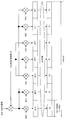
LTEでは、複数の端末から送信される複数のACK/NACK信号は、図2に示すように、時間軸上においてZero Auto-correlation特性を持つZAC(Zero Auto-correlation)系列によって拡散され(ZAC系列を乗算し)、PUCCH内においてコード多重されている。図2において、(W(0), W(1), W(2), W(3))は系列長4のウォルシュ(Walsh)系列を表し、(F(0),F(1),F(2))は系列長3のDFT(Discrete Fourier Transform)系列を表す。
In LTE, as shown in FIG. 2, a plurality of ACK / NACK signals transmitted from a plurality of terminals are spread by a ZAC (Zero-Auto-correlation) sequence having a Zero-Auto-correlation characteristic on the time axis (ZAC sequence). And code-multiplexed in PUCCH. In FIG. 2, (W (0), W (1), W (2), W (3)) represents a Walsh sequence having a sequence length of 4, and (F (0), F (1), F (2)) represents a DFT (Discrete Fourier Transform) sequence having a sequence length of 3.
図2に示すように、端末ではACK/NACK信号は、まず周波数軸上においてZAC系列(系列長12)によって1SC-FDMAシンボルに対応する周波数成分へ1次拡散される。つまり、系列長12のZAC系列に対して、複素数で表されるACK/NACK信号成分が乗算される。次に、1次拡散後のACK/NACK信号、及び、参照信号としてのZAC系列は、それぞれウォルシュ系列(系列長4: W(0)~W(3))及びDFT系列(系列長3: F(0)~F(2))によって2次拡散される。つまり、系列長12の信号(1次拡散後のACK/NACK信号、又は、参照信号としてのZAC系列)のそれぞれの成分に対して、直交符号系列(OCC:Orthogonal Cover Code, ウォルシュ系列又はDFT系列)の各成分が乗算される。さらに、2次拡散された信号は、逆離散フーリエ変換(IDFT: Inverse Discrete Fourier Transform。又はIFFT: Inverse Fast Fourier Transform)によって時間軸上の系列長12の信号に変換される。そして、IFFT後の信号のそれぞれに対して、サイクリックプリフィックス(CP:Cyclic Prefix)が付加され、7つのSC-FDMAシンボルからなる1スロットの信号が形成される。
As shown in FIG. 2, in the terminal, the ACK / NACK signal is first spread to the frequency component corresponding to the 1SC-FDMA symbol by the ZAC sequence (sequence length 12) on the frequency axis. That is, a ZAC sequence having a sequence length of 12 is multiplied by an ACK / NACK signal component represented by a complex number. Next, the first spread ACK / NACK signal and the ZAC sequence as a reference signal are a Walsh sequence (sequence length 4: W (0) to W (3)) and a DFT sequence (sequence length 3: F), respectively. Second-order diffusion is performed by (0) to F (2)). That is, an orthogonal code sequence (OCC: Orthogonal Cover Code, Walsh sequence or DFT sequence) for each component of a sequence length 12 signal (ACK / NACK signal after first spreading or ZAC sequence as a reference signal) ) Are multiplied. Further, the second-order spread signal is converted into a signal having a sequence length of 12 on the time axis by inverse discrete Fourier transform (IDFT: Inverse Discrete Fourier Transform) or IFFT: Inverse Fast Fourier Transform. Then, a cyclic prefix (CP: Cyclic Prefix) is added to each of the signals after IFFT to form a one-slot signal composed of seven SC-FDMA symbols.
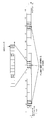
また、PUCCHは、図3に示すように、サブフレーム単位で各端末に割り当てられる。
Also, as shown in FIG. 3, PUCCH is assigned to each terminal in subframe units.
異なる端末からのACK/NACK信号同士は、異なる巡回シフト量(Cyclic Shift Index)で定義されるZAC系列、又は、異なる系列番号(OC Index: Orthogonal Cover Index)に対応する直交符号系列を用いて拡散(乗算)されている。直交符号系列は、ウォルシュ系列とDFT系列との組である。また、直交符号系列は、ブロックワイズ拡散コード系列(Block-wise spreading code)と称されることもある。したがって、基地局は、従来の逆拡散及び相関処理を用いることにより、これらのコード多重された複数のACK/NACK信号を分離することができる(例えば、非特許文献4を参照)。
ACK / NACK signals from different terminals are spread using ZAC sequences defined by different cyclic shift amounts (Cyclic Shift Index) or orthogonal code sequences corresponding to different sequence numbers (OC Index: Orthogonal Cover Index) (Multiplication). An orthogonal code sequence is a set of a Walsh sequence and a DFT sequence. In addition, the orthogonal code sequence may be referred to as a block-wise spreading code sequence. Therefore, the base station can separate a plurality of these code-multiplexed ACK / NACK signals by using conventional despreading and correlation processing (see, for example, Non-Patent Document 4).
また、LTEの上りリンクでは、基地局と端末との間の受信品質を測定するために、SRS(Sounding Reference Signal)が用いられる(例えば、非特許文献1を参照)。SRSは、端末から基地局に対して、SRSリソースにマッピングされて送信される。ここで、基地局は、セル固有の上位レイヤ通知によって、対象セル内に存在する全端末に共通するSRSリソース候補を含むSRSリソース候補グループを設定する。その後、端末単位の上位レイヤ通知によって、SRSリソース候補グループのサブセットとなるSRSリソースがSRSリソースの割当対象端末に対してそれぞれ割り当てられる。端末は、割り当てられたSRSリソースにSRSをマッピングして基地局へ送信する。なお、各SRSリソース候補は、SRSの送信候補となるサブフレーム(SRS送信候補サブフレーム)における最終SC-FDMAシンボルである。また、SRSリソース候補となるシンボルでは、SRSリソース候補グループが設定されたセル内の全端末がデータ送信を行わないことにより、SRSとデータ信号(PUSCH信号)との衝突が防止される。
Also, in LTE uplink, SRS (Sounding Reference Signal) is used to measure the reception quality between the base station and the terminal (for example, see Non-Patent Document 1). The SRS is mapped to the SRS resource and transmitted from the terminal to the base station. Here, the base station sets up an SRS resource candidate group including SRS resource candidates common to all terminals existing in the target cell by cell-specific higher layer notification. Thereafter, SRS resources, which are subsets of SRS resource candidate groups, are allocated to the allocation target terminals of the SRS resources by higher layer notification in units of terminals. The terminal maps the SRS to the allocated SRS resource and transmits it to the base station. Each SRS resource candidate is a final SC-FDMA symbol in a subframe (SRS transmission candidate subframe) that is a transmission candidate for SRS. In addition, in a symbol that is an SRS resource candidate, collision between the SRS and the data signal (PUSCH signal) is prevented by not transmitting data from all terminals in the cell in which the SRS resource candidate group is set.
LTEでは、SRSとPUCCHとが同一シンボルに存在する場合には、PUCCHを後半スロットの最終シンボルを除いた6シンボルで拡散し直交化して送信する「Shortened PUCCH format」が定義されている(例えば、非特許文献1を参照)。Shortened PUCCH formatでは、1次拡散後のACK/NACK信号は、DFT系列(系列長3: F(0)~F(2))によって2次拡散される。
In LTE, when SRS and PUCCH are present in the same symbol, “Shortened PUCCH format” is defined in which PUCCH is spread with six symbols excluding the last symbol of the second half slot, orthogonalized, and transmitted (for example, (Refer nonpatent literature 1). In Shortened PUCCH format, the first spread ACK / NACK signal is secondarily spread by a DFT sequence (sequence length 3: F (0) to F (2)).
LTEにおいて、SRSリソース候補グループを設定するセル固有の上位レイヤ通知として、srs-SubframeConfig等が定義されている(例えば、非特許文献1を参照)。図4は、srs-SubframeConfigの定義の一例を示す。図4に示すsrs-SubframeConfig番号(0~15)が基地局から端末へ送信されることによって、SRSを送信する送信間隔(TSFC)及びSRSの送信を開始するサブフレームを指示するためのオフセット量(ΔSFC)が、基地局から端末に対して指示される。例えば、図4において、srs-SubframeConfig番号が4(Binary=0100)である場合、送信間隔TSFC=5、オフセット量ΔSFC=1であるので、2(=1+ΔSFC)番目、7(=1+ΔSFC+(TSFC×1))番目、...、12(=1+ΔSFC+(TSFC×2))番目、(1+ΔSFC+(TSFC×n))番目のサブフレームが、SRS送信候補サブフレームとなる(例えば、図5を参照)。
In LTE, srs-SubframeConfig or the like is defined as a cell-specific upper layer notification for setting an SRS resource candidate group (see, for example, Non-Patent Document 1). FIG. 4 shows an example of the definition of srs-SubframeConfig. By transmitting the srs-SubframeConfig number (0 to 15) shown in FIG. 4 from the base station to the terminal, an offset for indicating a transmission interval (T SFC ) for transmitting SRS and a subframe for starting SRS transmission A quantity (Δ SFC ) is indicated from the base station to the terminal. For example, in FIG. 4, when the srs-SubframeConfig number is 4 (Binary = 0100), the transmission interval T SFC = 5 and the offset amount Δ SFC = 1, so the 2 (= 1 + Δ SFC ) th, 7 ( = 1 + Δ SFC + (T SFC × 1)), ..., 12 (= 1 + Δ SFC + (T SFC × 2)) th, (1 + Δ SFC + (T SFC × n)) th The subframe becomes an SRS transmission candidate subframe (see, for example, FIG. 5).
ところで、今後の情報社会を支える仕組みとして、近年、ユーザの判断を介することなく機器間の自律的な通信によりサービスを実現するM2M(Machine-to-Machine)通信が期待されている。M2Mシステムの具体的な応用事例としてスマートグリッドがある。スマートグリッドは、電気又はガスなどのライフラインを効率的に供給するインフラシステムであり、各家庭又はビルに配備されるスマートメータと中央サーバとの間でM2M通信を実施して、自律的かつ効果的に資源の需要バランスを調整する。M2M通信システムの他の応用事例として、物品管理、環境センシング又は遠隔医療などのためのモニタリングシステム、自動販売機の在庫又は課金の遠隔管理などが挙げられる。
By the way, in recent years, M2M (Machine-to-Machine) communication that realizes services through autonomous communication between devices without user judgment is expected as a mechanism that will support the future information society. A smart grid is a specific application example of the M2M system. A smart grid is an infrastructure system that efficiently supplies lifelines such as electricity or gas, and is autonomous and effective by implementing M2M communication between a smart meter deployed in each home or building and a central server. Adjust the balance of demand for resources. Other application examples of the M2M communication system include a monitoring system for goods management, environmental sensing or telemedicine, and remote management of vending machine inventory or billing.
M2M通信システムにおいては、特に広範な通信エリアを有するセルラシステムの利用が着目されている。3GPPでは、LTE及びLTE-Advancedの規格化において、マシンタイプ通信(MTC: Machine Type Communication)と呼ばれるM2M向けのセルラネットワーク高度化の標準化が行われており(例えば、非特許文献5)、低コスト化、消費電力削減、及びカバレッジ拡張(Coverage Enhancement)を要求条件として仕様検討が進められている。特に、ユーザが移動しながら利用することが多いハンドセット端末とは異なり、スマートメータなど、ほとんど移動の無い端末では、カバレッジの確保がサービス提供の上で必要な条件となる。そのため、ビルの地下などの既存のLTE及びLTE-Advancedの通信エリアにおいて、利用できない場所に対応する端末(MTC端末)が配置されている場合にも対応するため、通信エリアをさらに拡大する「カバレッジ拡張(MTCカバレッジ拡張)」は課題である。
In the M2M communication system, the use of a cellular system having a wide communication area is attracting attention. In 3GPP, in the standardization of LTE and LTE-Advanced, standardization of cellular network sophistication for M2M called machine type communication (MTC: Machine Type Communication) is performed (for example, Non-Patent Document 5), and low cost. The specifications are being studied under the requirements of networking, power consumption reduction, and coverage enhancement. In particular, unlike a handset terminal that a user often uses while moving, a terminal that hardly moves such as a smart meter is required to secure coverage. For this reason, in the existing LTE and LTE-Advanced communication areas such as the basement of buildings, even when terminals (MTC terminals) corresponding to places that cannot be used are arranged, the communication area is further expanded. “Extension (MTC coverage extension)” is an issue.
通信エリアを更に拡大するために、MTCカバレッジ拡張では、同一信号を複数回に渡って繰り返して送信する「レピティション」技術が検討されている。レピティションでは、送信側でレピティション送信された信号を合成することにより、受信信号電力を向上させ、カバレッジ(通信エリア)を拡張させる。
In order to further expand the communication area, in MTC coverage expansion, “repetition” technology that repeatedly transmits the same signal multiple times is being studied. In repetition, the signals transmitted by repetition on the transmission side are combined to improve the received signal power and expand the coverage (communication area).
更に、カバレッジ拡張の必要なMTC端末はほとんど移動がなく、チャネルの時間変動のない環境が想定されていることに着目して、チャネル推定精度を向上させる技術を用いることができる。
Furthermore, it is possible to use a technique for improving the channel estimation accuracy by paying attention to the assumption that there is almost no movement of MTC terminals that require coverage extension and there is no time variation of the channel.
チャネル推定精度を向上させる技術の1つとして、「複数サブフレームチャネル推定(cross-subframe channel estimation)及びシンボルレベル合成」がある(例えば、非特許文献6を参照)。複数サブフレームチャネル推定及びシンボルレベル合成では、図6に示すように、複数サブフレーム(NRepサブフレーム)に渡ってレピティション送信される信号に対して、基地局は、レピティション回数と同一又は少ないサブフレーム(Xサブフレーム)に渡ってシンボル単位で同相合成を行う。その後、基地局は、同相合成後のDMRSを用いてチャネル推定を行い、得られたチャネル推定結果を用いて、SC-FDMAデータシンボルの復調・復号を行う。
One technique for improving channel estimation accuracy is “cross-subframe channel estimation and symbol level synthesis” (see, for example, Non-Patent Document 6). In the multiple subframe channel estimation and symbol level synthesis, as shown in FIG. 6, the base station has the same number of repetitions as the number of repetitions for a signal transmitted by repetition over multiple subframes (N Rep subframes). In-phase synthesis is performed in symbol units over a few subframes (X subframes). Thereafter, the base station performs channel estimation using DMRS after in-phase combining, and demodulates and decodes SC-FDMA data symbols using the obtained channel estimation result.
複数サブフレームチャネル推定及びシンボルレベル合成が行われる単位であるサブフレーム数(X)がレピティション回数(NRep)よりも少ない場合、基地局は、復調・復号後の(NRep/X)シンボルを合成する。
When the number of subframes (X), which is a unit in which multi-subframe channel estimation and symbol level synthesis are performed, is smaller than the number of repetitions (N Rep ), the base station performs (N Rep / X) symbols after demodulation and decoding Is synthesized.
複数サブフレームチャネル推定及びシンボルレベル合成を用いることにより、サブフレーム単位でチャネル推定及びSC-FDMAデータシンボルの復調・復号を行う単純なレピティションと比較して、PUSCH及びPUCCHの伝送品質を改善できることが明らかになっている(例えば、非特許文献6を参照)。
By using multiple subframe channel estimation and symbol level synthesis, the transmission quality of PUSCH and PUCCH can be improved compared to simple repetition that performs channel estimation and SC-FDMA data symbol demodulation / decoding in units of subframes. (For example, see Non-Patent Document 6).
MTC端末をサポートするセルでは、MTC端末と、既存のLTE端末とを共存させることが必要であり、かつ、既存のLTEシステムへの影響を最小限に抑えるようにMTC端末をサポートすることが望ましい。そのため、レピティション送信が必要なMTC端末(MTCカバレッジ拡張端末)の上りリンク送信(例えば、PUSCH送信)においても、既存LTEシステムのSRSとの衝突を防止するために、SRSリソース候補ではデータ送信を行わない。これにより、SRSとMTCカバレッジ拡張端末のデータ信号との衝突を防止する。
In a cell that supports MTC terminals, it is necessary for MTC terminals to coexist with existing LTE terminals, and it is desirable to support MTC terminals so as to minimize the impact on existing LTE systems. . Therefore, in uplink transmission (for example, PUSCH transmission) of an MTC terminal (MTC coverage extension terminal) that requires repetition transmission, in order to prevent collision with the SRS of the existing LTE system, data transmission is performed in the SRS resource candidate. Not performed. This prevents a collision between the SRS and the data signal of the MTC coverage extension terminal.
PUSCHのレピティションにおいて、端末がSRS送信候補サブフレームでデータを送信するフォーマットとして、以下の2つの方法がある。
In the PUSCH repetition, there are the following two methods for transmitting data in the SRS transmission candidate subframe by the terminal.
1つは、他のサブフレームと同様にして図1に示すようにDMRSを除いた12SC-FDMAシンボルにデータをマッピングした後、SRSリソース候補である最終SC-FDMAシンボルをパンクチャする方法である(例えば、非特許文献7を参照)。この方法では、SRS送信候補サブフレームと他のサブフレームとで、最終SC-FDMAシンボルを除く各シンボルは同一の信号を送信しているため、基地局側で同相合成が容易に実現できる。
One is a method of puncturing the final SC-FDMA symbol which is an SRS resource candidate after mapping data to 12SC-FDMA symbols excluding DMRS as shown in FIG. For example, refer nonpatent literature 7.). In this method, since the symbols other than the final SC-FDMA symbol transmit the same signal in the SRS transmission candidate subframe and other subframes, in-phase combining can be easily realized on the base station side.
もう1つの方法は、SRS送信候補サブフレームでデータを送信するフォーマットとして、他のサブフレームとはデータに対する符号化率を変えて、最終SC-FDMAシンボルを除いた11SC-FDMAシンボルにデータをマッピングする(Rate matching)方法である(例えば、非特許文献8を参照)。この方法は、レピティション送信を想定していない既存のLTEにおいて用いられている方法であるため、既存の規格からの変更を必要としない。一方で、SRS送信候補サブフレームと他のサブフレームとで各シンボルは異なる信号を送信するため、基地局側で同相合成はできなくなる。
Another method is to format the data to be transmitted in the SRS transmission candidate subframes, mapping the data to 11SC-FDMA symbols excluding the last SC-FDMA symbol by changing the coding rate for the data from other subframes. (Rate matching) method (see, for example, Non-Patent Document 8). Since this method is a method used in existing LTE that does not assume repetition transmission, no change from the existing standard is required. On the other hand, since each symbol transmits a different signal in the SRS transmission candidate subframe and the other subframe, in-phase combining cannot be performed on the base station side.
一方、PUCCHレピティションにおいても、PUSCHの場合と同様、端末がSRS送信候補サブフレームでACK/NACK信号を送信するフォーマットとして、以下の2つの方法が考えられる。
On the other hand, also in PUCCH repetition, as in the case of PUSCH, the following two methods can be considered as a format in which a terminal transmits an ACK / NACK signal in an SRS transmission candidate subframe.
1つは、他のサブフレームと同様にして図2及び図3に示すように、通常のPUCCHフォーマット(Normal PUCCH format)を用いて、ACK/NACK信号及び参照信号をマッピングした後、SRSリソース候補である最終SC-FDMAシンボルをパンクチャする方法である。しかし、この方法では、OCCの一部をパンクチャすることになるため、OCC系列間の直交性の崩れが発生し、符号間干渉により特性が劣化する恐れがある。
One is the same as other subframes, as shown in FIG. 2 and FIG. 3, after mapping an ACK / NACK signal and a reference signal using a normal PUCCH format (Normal-PUCCH-format), SRS resource candidates Is a method of puncturing the last SC-FDMA symbol. However, in this method, a part of the OCC is punctured, so that the orthogonality between OCC sequences is lost, and the characteristics may be deteriorated due to intersymbol interference.
もう1つの方法は、SRS送信候補サブフレームでACK/NACK信号を送信するフォーマットとして、Shortened PUCCHフォーマットを用いる方法である。しかしながら、この方法では、SRS送信候補サブフレームと他のサブフレームとで、ACK/NACK信号に対して異なるOCC系列が乗算されているため、基地局側で逆拡散をする前の信号を同相合成することができず、基地局での復調の処理が複雑化してしまう。
Another method is to use the Shortened PUCCH format as the format for transmitting the ACK / NACK signal in the SRS transmission candidate subframe. However, in this method, different OCC sequences are multiplied for the ACK / NACK signal in the SRS transmission candidate subframe and other subframes, so that the signal before despreading at the base station side is subjected to in-phase synthesis Therefore, the demodulation process at the base station becomes complicated.
本開示の一態様は、SRS送信候補サブフレームを含む場合でも、複数サブフレームチャネル推定及びシンボルレベル合成によって、チャネル推定精度を向上させることができる基地局、端末、受信方法及び送信方法を提供する。
An aspect of the present disclosure provides a base station, a terminal, a reception method, and a transmission method capable of improving channel estimation accuracy by multi-subframe channel estimation and symbol level synthesis even when including SRS transmission candidate subframes .
本開示の一態様に係る端末は、上りリンク信号を複数のサブフレームに渡ってレピティションしてレピティション信号を生成するレピティション部と、前記複数のサブフレームの中に、上りリンクの受信品質の測定に用いられるサウンディング参照信号(SRS)の送信候補サブフレームが含まれない場合、前記複数のサブフレームの全てに第1の送信フォーマットを設定し、前記複数のサブフレームの中に、前記送信候補サブフレームが含まれる場合、前記複数のサブフレームの全てに第2の送信フォーマットを設定する制御部と、前記設定された送信フォーマットで前記レピティション信号を送信する送信部と、を具備する構成を採る。
A terminal according to an aspect of the present disclosure includes a repetition unit that repeats an uplink signal over a plurality of subframes to generate a repetition signal, and an uplink reception quality in the plurality of subframes. When a sounding reference signal (SRS) transmission candidate subframe used for measurement of the first subframe is not included, a first transmission format is set in all of the plurality of subframes, and the transmission is included in the plurality of subframes. A configuration comprising a control unit that sets a second transmission format in all of the plurality of subframes when a candidate subframe is included, and a transmission unit that transmits the repetition signal in the set transmission format Take.
なお、これらの包括的または具体的な態様は、システム、方法、集積回路、コンピュータプログラム、または、記録媒体で実現されてもよく、システム、装置、方法、集積回路、コンピュータプログラムおよび記録媒体の任意な組み合わせで実現されてもよい。
Note that these comprehensive or specific aspects may be realized by a system, method, integrated circuit, computer program, or recording medium. Any of the system, apparatus, method, integrated circuit, computer program, and recording medium may be used. It may be realized by various combinations.
本開示の一態様によれば、SRS送信候補サブフレームを含む場合でも、複数サブフレームチャネル推定及びシンボルレベル合成によってチャネル推定精度を向上させることができる。
According to one aspect of the present disclosure, even when SRS transmission candidate subframes are included, channel estimation accuracy can be improved by multi-subframe channel estimation and symbol level synthesis.
本開示の一態様における更なる利点および効果は、明細書および図面から明らかにされる。かかる利点および/または効果は、いくつかの実施形態並びに明細書および図面に記載された特徴によってそれぞれ提供されるが、1つまたはそれ以上の同一の特徴を得るために必ずしも全てが提供される必要はない。
Further advantages and effects of one aspect of the present disclosure will become apparent from the specification and drawings. Such advantages and / or effects are provided by some embodiments and features described in the description and drawings, respectively, but all need to be provided in order to obtain one or more identical features. There is no.
以下、本開示の実施の形態について図面を参照して詳細に説明する。
Hereinafter, embodiments of the present disclosure will be described in detail with reference to the drawings.
[通信システムの概要]
本開示の各実施の形態に係る通信システムは、例えば、LTE-Advancedシステムに対応する基地局100及び端末200を備える。 [Outline of communication system]
The communication system according to each embodiment of the present disclosure includes, for example, abase station 100 and a terminal 200 that are compatible with the LTE-Advanced system.
本開示の各実施の形態に係る通信システムは、例えば、LTE-Advancedシステムに対応する基地局100及び端末200を備える。 [Outline of communication system]
The communication system according to each embodiment of the present disclosure includes, for example, a
また、基地局100のセル内に、MTCカバレッジ拡張モードが適用される端末200(MTCカバレッジ拡張端末)が存在している場合を想定する。端末200は、例えば、MTCカバレッジ拡張モードが適用される場合、上述したチャネル推定精度を向上させる技術を適用する。
In addition, it is assumed that a terminal 200 (MTC coverage extension terminal) to which the MTC coverage extension mode is applied exists in the cell of the base station 100. For example, when the MTC coverage extension mode is applied, the terminal 200 applies the technique for improving the channel estimation accuracy described above.
また、LTE-Advanced Release 13で仕様検討が進められているMTCでは、上述したチャネル推定精度を向上させる技術を適用するために、Xサブフレーム中では同一リソースで信号が送信される(例えば、非特許文献9を参照)。
In addition, in the MTC whose specifications are being studied in LTE-Advanced Release 13, a signal is transmitted using the same resource in the X subframe in order to apply the above-described technique for improving the channel estimation accuracy (for example, non-transmission). (See Patent Document 9).
また、上述したように、LTEにおいて、SRSリソース候補グループを設定するセル固有の上位レイヤ通知の一例として、図4に示すsrs-SubframeConfig等が定義されているものとする。つまり、SRSを送信する送信間隔(TSFC)及びSRSの送信を開始するサブフレームを指示するためのオフセット量(ΔSFC)が基地局100から端末200へ通知される。そのため、端末200は、Xサブフレーム連続でレピティション信号を送信する区間において、SRS送信候補サブフレームが存在するか否かを特定することができる。よって、端末200は、SRS送信候補サブフレームの最終SC-FDMAシンボル(SRSリソース候補)においてデータ送信を行わないことにより、SRSとデータ信号との衝突を防止する。
Further, as described above, srs-SubframeConfig and the like illustrated in FIG. 4 are defined as an example of a cell-specific upper layer notification for setting an SRS resource candidate group in LTE. That is, base station 100 notifies terminal 200 of a transmission interval (T SFC ) for transmitting SRS and an offset amount (Δ SFC ) for indicating a subframe for starting SRS transmission. Therefore, terminal 200 can specify whether or not there is an SRS transmission candidate subframe in a section in which a repetition signal is transmitted in X subframes continuously. Therefore, terminal 200 prevents collision between the SRS and the data signal by not performing data transmission in the last SC-FDMA symbol (SRS resource candidate) of the SRS transmission candidate subframe.
更に、本開示の各実施の形態では、端末200は、PUCCHレピティション送信において、Xサブフレーム連続でレピティション信号を送信する区間において、SRS送信候補サブフレームが存在するか否かに応じて、Xサブフレーム全ての送信フォーマットを設定する。これにより、PUCCHレピティションにおいて、OCC系列間の直交性の崩れの影響を低減しつつ、基地局において複数サブフレームチャネル推定及びシンボルレベル合成によってチャネル推定精度を向上させることができる。
Furthermore, in each embodiment of the present disclosure, in the PUCCH repetition transmission, the terminal 200 determines whether or not there is an SRS transmission candidate subframe in a section in which a repetition signal is transmitted in X subframes continuously. Sets the transmission format for all X subframes. As a result, in the PUCCH repetition, it is possible to improve the channel estimation accuracy by multi-subframe channel estimation and symbol level synthesis in the base station while reducing the influence of the loss of orthogonality between OCC sequences.
以下、一例として、PUCCHレピティションにおいて複数サブフレームチャネル推定及びシンボルレベル合成によってチャネル推定精度を向上させる方法について説明する。
Hereinafter, as an example, a method for improving channel estimation accuracy by multi-subframe channel estimation and symbol level synthesis in PUCCH repetition will be described.
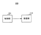
図7は本開示の実施の形態に係る基地局100の要部構成を示すブロック図である。図7に示す基地局100において、制御部101は、上りリンク信号がレピティションされる複数のサブフレームの中に、SRS送信候補サブフレームが含まれない場合、複数のサブフレームの全てに第1の送信フォーマットを設定し、複数のサブフレームの中に、SRS送信候補サブフレームが含まれる場合、複数のサブフレームの全てに第2の送信フォーマットを設定し、受信部113は、設定された送信フォーマットでレピティション信号を受信する。
FIG. 7 is a block diagram illustrating a main configuration of the base station 100 according to the embodiment of the present disclosure. In the base station 100 illustrated in FIG. 7, when the SRS transmission candidate subframe is not included in the plurality of subframes in which the uplink signal is repeated, the control unit 101 includes the first in all the plurality of subframes. When the SRS transmission candidate subframe is included in the plurality of subframes, the second transmission format is set in all of the plurality of subframes, and the receiving unit 113 sets the set transmission format. Receive a repetition signal in format.
また、図8は、本開示の各実施の形態に係る端末200の要部構成を示すブロック図である。図8に示す端末200において、レピティション部213は、上りリンク信号を複数のサブフレームに渡ってレピティションしてレピティション信号を生成し、制御部209は、複数のサブフレームの中に、SRS送信候補サブフレームが含まれない場合、複数のサブフレームの全てに第1の送信フォーマットを設定し、複数のサブフレームの中に、SRS送信候補サブフレームが含まれる場合、複数のサブフレームの全てに第2の送信フォーマットを設定し、送信部217は、設定された送信フォーマットでレピティション信号を送信する。
FIG. 8 is a block diagram showing a main configuration of the terminal 200 according to each embodiment of the present disclosure. In terminal 200 shown in FIG. 8, repetition section 213 repeats the uplink signal over a plurality of subframes to generate a repetition signal, and control section 209 includes SRS in the plurality of subframes. When the transmission candidate subframe is not included, the first transmission format is set in all of the plurality of subframes. When the SRS transmission candidate subframe is included in the plurality of subframes, all of the plurality of subframes are included. And the transmission unit 217 transmits a repetition signal in the set transmission format.
(実施の形態1)
[基地局の構成]
図9は、本開示の実施の形態1に係る基地局100の構成を示すブロック図である。図9において、基地局100は、制御部101と、制御信号生成部102と、制御信号符号化部103と、制御信号変調部104と、データ符号化部105と、再送制御部106と、データ変調部107と、信号割当部108と、IFFT(Inverse Fast Fourier Transform)部109と、CP(Cyclic Prefix)付加部110と、送信部111と、アンテナ112と、受信部113と、CP除去部114と、PUCCH抽出部115と、合成部116と、デマッピング部117と、チャネル推定部118と、等化部119と、逆拡散部120と、相関処理部121と、判定部122と、を有する。 (Embodiment 1)
[Base station configuration]
FIG. 9 is a block diagram illustrating a configuration ofbase station 100 according to Embodiment 1 of the present disclosure. In FIG. 9, the base station 100 includes a control unit 101, a control signal generation unit 102, a control signal encoding unit 103, a control signal modulation unit 104, a data encoding unit 105, a retransmission control unit 106, data Modulation section 107, signal allocation section 108, IFFT (Inverse Fast Fourier Transform) section 109, CP (Cyclic Prefix) addition section 110, transmission section 111, antenna 112, reception section 113, and CP removal section 114 A PUCCH extraction unit 115, a synthesis unit 116, a demapping unit 117, a channel estimation unit 118, an equalization unit 119, a despreading unit 120, a correlation processing unit 121, and a determination unit 122. .
[基地局の構成]
図9は、本開示の実施の形態1に係る基地局100の構成を示すブロック図である。図9において、基地局100は、制御部101と、制御信号生成部102と、制御信号符号化部103と、制御信号変調部104と、データ符号化部105と、再送制御部106と、データ変調部107と、信号割当部108と、IFFT(Inverse Fast Fourier Transform)部109と、CP(Cyclic Prefix)付加部110と、送信部111と、アンテナ112と、受信部113と、CP除去部114と、PUCCH抽出部115と、合成部116と、デマッピング部117と、チャネル推定部118と、等化部119と、逆拡散部120と、相関処理部121と、判定部122と、を有する。 (Embodiment 1)
[Base station configuration]
FIG. 9 is a block diagram illustrating a configuration of
制御部101は、基地局100がカバーするセルに存在する複数の既存のLTE端末の各々に必要なSRSリソースの量を考慮して、セルにおけるSRSリソース候補グループを決定し、決定したSRSリソース候補グループを示す情報を制御信号生成部102へ出力する。SRSリソース候補グループは、例えば、図4に示すテーブルから選択される。
The control unit 101 determines the SRS resource candidate group in the cell in consideration of the amount of SRS resources necessary for each of a plurality of existing LTE terminals existing in the cell covered by the base station 100, and determines the determined SRS resource candidate Information indicating the group is output to the control signal generation unit 102. For example, the SRS resource candidate group is selected from the table shown in FIG.
また、制御部101は、決定したSRSリソース候補グループに関する情報に基づいて、PUCCHレピティションにおける各サブフレームのPUCCHフォーマットを決定し、決定したPUCCHフォーマットを示す情報を合成部116へ出力する。
Also, the control unit 101 determines the PUCCH format of each subframe in the PUCCH repetition based on the information related to the determined SRS resource candidate group, and outputs information indicating the determined PUCCH format to the combining unit 116.
また、制御部101は、MTCカバレッジ拡張端末に対してPDSCHの割当を決定する。このとき、制御部101は、MTCカバレッジ拡張端末に対して指示する周波数割当リソース及び変調・符号化方法などを決定し、決定したパラメータに関する情報を制御信号生成部102に出力する。
Also, the control unit 101 determines PDSCH allocation to the MTC coverage extension terminal. At this time, the control unit 101 determines a frequency allocation resource and a modulation / coding method to be instructed to the MTC coverage extension terminal, and outputs information on the determined parameter to the control signal generation unit 102.
また、制御部101は、制御信号に対する符号化レベルを決定し、決定した符号化レベルを制御信号符号化部103に出力する。また、制御部101は、制御信号及び下りリンクデータをマッピングする無線リソース(下りリソース)を決定し、決定した無線リソースに関する情報を信号割当部108に出力する。また、制御部101は、リソース割当対象端末200に対して、下りリンクデータ(送信データ)を送信する際に用いる符号化率を決定し、決定した符号化率をデータ符号化部105へ出力する。
Also, the control unit 101 determines the encoding level for the control signal, and outputs the determined encoding level to the control signal encoding unit 103. In addition, the control unit 101 determines a radio resource (downlink resource) for mapping the control signal and downlink data, and outputs information on the determined radio resource to the signal allocation unit 108. Further, the control unit 101 determines a coding rate used when transmitting downlink data (transmission data) to the resource allocation target terminal 200 and outputs the determined coding rate to the data coding unit 105. .
また、制御部101は、MTCカバレッジ拡張端末のカバレッジ拡張レベルを決定し、決定したカバレッジ拡張レベルに関する情報、又は、決定したカバレッジ拡張レベルでのPUCCH送信に必要なレピティション回数を、制御信号生成部102及び合成部116に出力する。また、制御部101は、カバレッジ拡張レベルに関する情報又はPUCCH送信に必要なレピティション回数に基づいて、MTCカバレッジ拡張端末がPUCCHレピティションに用いるパラメータXの値に関する情報を生成し、生成した情報を制御信号生成部102へ出力する。
Further, the control unit 101 determines the coverage extension level of the MTC coverage extension terminal, and determines the information related to the determined coverage extension level or the number of times of repetition necessary for PUCCH transmission at the determined coverage extension level. 102 and the combining unit 116. Further, the control unit 101 generates information on the value of the parameter X used by the MTC coverage extension terminal for PUCCH repetition based on the information on the coverage extension level or the number of repetitions necessary for PUCCH transmission, and controls the generated information. Output to the signal generation unit 102.
また、制御部101は、端末200がPUCCHを送信するリソース(巡回シフト、直交符号系列、周波数)を決定する。制御部101は、PUCCH送信に用いられている可能性がある巡回シフト量及び直交符号系列を、逆拡散部120及び相関処理部121へそれぞれ出力し、PUCCH送信に使用される周波数リソースに関する情報をPUCCH抽出部115へ出力する。なお、これらのPUCCHリソースに関する情報は、端末200に対して、Implicitに通知されてもよく、端末200固有の上位レイヤのシグナリングによって端末200(後述する制御部209)へ通知されてもよい。
Also, the control unit 101 determines resources (cyclic shift, orthogonal code sequence, frequency) for the terminal 200 to transmit PUCCH. The control unit 101 outputs a cyclic shift amount and an orthogonal code sequence that may be used for PUCCH transmission to the despreading unit 120 and the correlation processing unit 121, respectively, and information on frequency resources used for PUCCH transmission. The data is output to the PUCCH extraction unit 115. Note that information regarding these PUCCH resources may be reported to the terminal 200 in an Implicit manner, or may be notified to the terminal 200 (a control unit 209 described later) by higher layer signaling unique to the terminal 200.
制御信号生成部102は、MTCカバレッジ拡張端末向けの制御信号を生成する。制御信号には、セル固有の上位レイヤの信号、端末固有の上位レイヤの信号、又は、PDSCHの割当を指示する下りリンク割当情報が含まれる。
The control signal generation unit 102 generates a control signal for the MTC coverage extension terminal. The control signal includes a cell-specific upper layer signal, a terminal-specific upper layer signal, or downlink allocation information instructing PDSCH allocation.
下りリンク割当情報は、複数のビットから構成されており、周波数割当リソース、変調・符号化方式などを指示する情報を含む。また、下りリンク割当情報には、カバレッジ拡張レベルに関する情報又はPUCCH送信に必要なレピティション回数、及び、PUCCHレピティションに用いるパラメータXの値に関する情報も含まれてもよい。
The downlink allocation information is composed of a plurality of bits, and includes information indicating frequency allocation resources, modulation / coding schemes, and the like. The downlink allocation information may also include information on the coverage extension level or the number of repetitions required for PUCCH transmission and information on the value of the parameter X used for PUCCH repetition.
制御信号生成部102は、制御部101から入力される制御情報を用いて、制御情報ビット列を生成し、生成した制御情報ビット列(制御信号)を制御信号符号化部103へ出力する。なお、制御情報が複数の端末200向けに送信されることもあるため、制御信号生成部102は、各端末200向けの制御情報に、各端末200の端末IDを含めてビット列を生成する。例えば、制御情報には、宛先端末の端末IDによってマスキングされたCRC(Cyclic Redundancy Check)ビットが付加される。
The control signal generation unit 102 generates a control information bit string using the control information input from the control unit 101, and outputs the generated control information bit string (control signal) to the control signal encoding unit 103. Since the control information may be transmitted to a plurality of terminals 200, the control signal generation unit 102 generates a bit string including the terminal ID of each terminal 200 in the control information for each terminal 200. For example, a CRC (Cyclic Redundancy Check) bit masked by the terminal ID of the destination terminal is added to the control information.
また、SRSリソース候補グループの情報は、セル固有の上位レイヤ信号により、MTCカバレッジ拡張端末(後述する制御部209)へ通知される。カバレッジ拡張レベルに関する情報又はPUCCH送信に必要なレピティション回数は、端末固有の上位レイヤのシグナリングによりMTCカバレッジ拡張端末へ通知されてもよく、上述したようにPDSCHの割当を指示する下りリンク割当情報を用いて通知されてもよい。また、PUCCHレピティションに用いるパラメータXの値に関する情報は、同様に、端末固有の上位レイヤのシグナリングによりMTCカバレッジ拡張端末へ通知されてもよく、PDSCHの割当を指示する下りリンク割当情報を用いて通知されてもよい。更に、PUCCHレピティションに用いるパラメータXの値に関する情報は、predefinedに規格上決まったパラメータである場合には、基地局100から端末へ通知されなくてもよい。
Also, the information of the SRS resource candidate group is notified to the MTC coverage extension terminal (a control unit 209 described later) by a cell-specific upper layer signal. Information related to the coverage extension level or the number of repetitions required for PUCCH transmission may be notified to the MTC coverage extension terminal by terminal-specific higher layer signaling, and the downlink assignment information for instructing PDSCH assignment as described above. May be used for notification. Also, information regarding the value of parameter X used for PUCCH repetition may be similarly notified to the MTC coverage extension terminal by terminal-specific higher layer signaling, using downlink allocation information instructing PDSCH allocation. You may be notified. Further, information regarding the value of the parameter X used for PUCCH repetition may not be notified from the base station 100 to the terminal when the parameter is a parameter determined in the standard according to predefined.
制御信号符号化部103は、制御部101から指示された符号化レベルに従って、制御信号生成部102から受け取る制御信号(制御情報ビット列)を符号化し、符号化後の制御信号を制御信号変調部104へ出力する。
The control signal encoding unit 103 encodes the control signal (control information bit string) received from the control signal generation unit 102 according to the encoding level instructed by the control unit 101, and the control signal modulation unit 104 outputs the encoded control signal. Output to.
制御信号変調部104は、制御信号符号化部103から受け取る制御信号を変調し、変調後の制御信号(シンボル列)を信号割当部108へ出力する。
Control signal modulation section 104 modulates the control signal received from control signal encoding section 103 and outputs the modulated control signal (symbol sequence) to signal allocation section 108.
データ符号化部105は、制御部101から受け取る符号化率に従って、送信データ(下りリンクデータ)に対してターボ符号などの誤り訂正符号化を施し、符号化後のデータ信号を再送制御部106へ出力する。
Data coding section 105 performs error correction coding such as turbo code on transmission data (downlink data) according to the coding rate received from control section 101, and sends the coded data signal to retransmission control section 106. Output.
再送制御部106は、初回送信時には、データ符号化部105から受け取る符号化後のデータ信号を保持するとともにデータ変調部107へ出力する。再送制御部106は、符号化後のデータ信号を宛先端末毎に保持する。また、再送制御部106は、送信したデータ信号に対するNACKを判定部122から受け取ると、対応する保持データをデータ変調部107へ出力する。再送制御部106は、送信したデータ信号に対するACKを判定部122から受け取ると、対応する保持データを削除する。
The retransmission control unit 106 holds the encoded data signal received from the data encoding unit 105 and outputs it to the data modulation unit 107 during the initial transmission. The retransmission control unit 106 holds the encoded data signal for each destination terminal. In addition, upon receiving NACK for the transmitted data signal from determination unit 122, retransmission control unit 106 outputs corresponding retained data to data modulation unit 107. Upon receiving an ACK for the transmitted data signal from determination unit 122, retransmission control unit 106 deletes the corresponding retained data.
データ変調部107は、再送制御部106から受け取るデータ信号を変調して、データ変調信号を信号割当部108へ出力する。
The data modulation unit 107 modulates the data signal received from the retransmission control unit 106 and outputs the data modulation signal to the signal allocation unit 108.
信号割当部108は、制御信号変調部104から受け取る制御信号(シンボル列)及びデータ変調部107から受け取るデータ変調信号を、制御部101から指示される無線リソースにマッピングする。なお、制御信号がマッピングされる対象となる制御チャネルは、MTC用のPDCCH(下りリンク制御チャネル(PDCCH:Physical Downlink Control Channel))でもよく、EPDCCH(Enhanced PDCCH)でもよい。信号割当部108は、制御信号がマッピングされたMTC用のPDCCH又はEPDCCHを含む下りリンクサブフレームの信号をIFFT部109に出力する。
The signal allocating unit 108 maps the control signal (symbol sequence) received from the control signal modulating unit 104 and the data modulated signal received from the data modulating unit 107 to radio resources instructed by the control unit 101. The control channel to which the control signal is mapped may be a PDCCH for MTC (downlink control channel (PDCCH)) or EPDCCH (enhanced PDCCH). The signal allocation unit 108 outputs a downlink subframe signal including the MDC PDCCH or EPDCCH to which the control signal is mapped to the IFFT unit 109.
IFFT部109は、信号割当部108から受け取る信号に対してIFFT処理を行うことにより、周波数領域信号を時間領域信号に変換する。IFFT部109は、時間領域信号をCP付加部110へ出力する。
The IFFT unit 109 converts the frequency domain signal into a time domain signal by performing IFFT processing on the signal received from the signal allocation unit 108. IFFT section 109 outputs the time domain signal to CP adding section 110.
CP付加部110は、IFFT部109から受け取る信号に対してCPを付加し、CP付加後の信号(OFDM信号)を送信部111へ出力する。
CP adding section 110 adds a CP to the signal received from IFFT section 109 and outputs the signal after the CP addition (OFDM signal) to transmitting section 111.
送信部111は、CP付加部110から受け取るOFDM信号に対してD/A(Digital-to-Analog)変換、アップコンバート等のRF(Radio Frequency)処理を行い、アンテナ112を介して端末200に無線信号を送信する。
Transmitting section 111 performs RF (Radio-Frequency) processing such as D / A (Digital-to-Analog) conversion and up-conversion on the OFDM signal received from CP adding section 110, and wirelessly transmits to terminal 200 via antenna 112. Send a signal.
受信部113は、アンテナ112を介して受信された端末200からの上りリンク信号(PUCCH)に対して、ダウンコンバート又はA/D(Analog-to-Digital)変換などのRF処理を行い、得られる受信信号をCP除去部114に出力する。端末200から送信される上りリンク信号(PUCCH)には、複数のサブフレームに渡るレピティション処理された信号が含まれる。
The reception unit 113 is obtained by performing RF processing such as down-conversion or A / D (Analog-to-Digital) conversion on the uplink signal (PUCCH) received from the terminal 200 via the antenna 112. The received signal is output to CP removing section 114. The uplink signal (PUCCH) transmitted from terminal 200 includes a repetition processed signal over a plurality of subframes.
CP除去部114は、受信部113から受け取る受信信号に付加されているCPを除去し、CP除去後の信号をPUCCH抽出部115へ出力する。
The CP removal unit 114 removes the CP added to the reception signal received from the reception unit 113 and outputs the signal after the CP removal to the PUCCH extraction unit 115.
PUCCH抽出部115は、制御部101から受け取るPUCCHリソースに関する情報に基づいて、CP除去部114から受け取る信号に対してFFT処理を適用し、周波数領域の信号系列に分解して、PUCCHに対応する信号を抽出し、抽出したPUCCH信号を合成部116へ出力する。
The PUCCH extraction unit 115 applies FFT processing to the signal received from the CP removal unit 114 based on information on the PUCCH resource received from the control unit 101, decomposes the signal into a frequency domain signal sequence, and outputs a signal corresponding to the PUCCH And the extracted PUCCH signal is output to the synthesis unit 116.
合成部116は、制御部101から入力される、PUCCHレピティションに関する情報、及び、各サブフレームのPUCCHフォーマットに関する情報を用いて、レピティション送信された複数サブフレームに渡るPUCCHに対して、シンボルレベル合成を用いて、応答信号及び参照信号に相当する部分の信号を同相合成する。合成部116は、合成後の信号をデマッピング部117へ出力する。
The combining unit 116 uses the information related to the PUCCH repetition and the information related to the PUCCH format of each subframe input from the control unit 101 to the symbol level for the PUCCH over multiple subframes transmitted by repetition. Using synthesis, the signals corresponding to the response signal and the reference signal are synthesized in phase. The combining unit 116 outputs the combined signal to the demapping unit 117.
デマッピング部117は、制御部101から入力される、サブフレームのPUCCHフォーマットに関する情報を用いて、合成部116から受け取る信号(PUCCHのサブフレーム部分)を、参照信号と応答信号とに分解し、参照信号をチャネル推定部118に出力し、応答信号を等化部119に出力する。
The demapping unit 117 uses the information related to the PUCCH format of the subframe input from the control unit 101 to decompose the signal received from the combining unit 116 (the subframe portion of the PUCCH) into a reference signal and a response signal, The reference signal is output to channel estimation section 118, and the response signal is output to equalization section 119.
チャネル推定部118は、デマッピング部117から入力される参照信号を用いてチャネル推定を行う。チャネル推定部118は、得られたチャネル推定値を等化部119に出力する。
The channel estimation unit 118 performs channel estimation using the reference signal input from the demapping unit 117. Channel estimation section 118 outputs the obtained channel estimation value to equalization section 119.
等化部119は、チャネル推定部118から入力されるチャネル推定値を用いて、デマッピング部117から入力される応答信号の等化を行う。等化部119は、等化後の応答信号を逆拡散部120へ出力する。
The equalization unit 119 equalizes the response signal input from the demapping unit 117 using the channel estimation value input from the channel estimation unit 118. The equalization unit 119 outputs the equalized response signal to the despreading unit 120.
逆拡散部120は、制御部101から受け取る直交符号系列(端末200が用いるべき直交符号系列)を用いて、等化部119から受け取る信号のうち応答信号に相当する部分の信号を逆拡散し、逆拡散後の信号を相関処理部121に出力する。
The despreading unit 120 uses the orthogonal code sequence received from the control unit 101 (orthogonal code sequence to be used by the terminal 200) to despread the signal corresponding to the response signal among the signals received from the equalization unit 119. The despread signal is output to correlation processing section 121.
相関処理部121は、制御部101から入力されるZAC系列(端末200が用いる可能性のあるZAC系列。巡回シフト量)と、逆拡散部120から入力される信号との相関値を求めて、相関値を判定部122に出力する。
The correlation processing unit 121 obtains a correlation value between the ZAC sequence input from the control unit 101 (ZAC sequence that the terminal 200 may use, the cyclic shift amount) and the signal input from the despreading unit 120, The correlation value is output to the determination unit 122.
判定部122は、相関処理部121から受け取る相関値に基づいて、端末200から送信された応答信号が、送信されたデータに対してACK又はNACKのいずれかを示しているかを判定する。判定部122は、判定結果を再送制御部106に出力する。
Based on the correlation value received from the correlation processing unit 121, the determination unit 122 determines whether the response signal transmitted from the terminal 200 indicates ACK or NACK for the transmitted data. The determination unit 122 outputs the determination result to the retransmission control unit 106.
[端末の構成]
図10は、本開示の実施の形態1に係る端末200の構成を示すブロック図である。図10において、端末200は、アンテナ201と、受信部202と、CP除去部203と、FFT部204と、抽出部205と、データ復調部206と、データ復号部207と、CRC部208と、制御部209と、応答信号生成部210と、変調部211と、拡散部212と、レピティション部213と、信号割当部214と、IFFT部215と、CP付加部216と、送信部217と、を有する。 [Terminal configuration]
FIG. 10 is a block diagram showing a configuration ofterminal 200 according to Embodiment 1 of the present disclosure. 10, terminal 200 includes an antenna 201, a receiving unit 202, a CP removing unit 203, an FFT unit 204, an extracting unit 205, a data demodulating unit 206, a data decoding unit 207, a CRC unit 208, A control unit 209, a response signal generation unit 210, a modulation unit 211, a spreading unit 212, a repetition unit 213, a signal allocation unit 214, an IFFT unit 215, a CP addition unit 216, a transmission unit 217, Have
図10は、本開示の実施の形態1に係る端末200の構成を示すブロック図である。図10において、端末200は、アンテナ201と、受信部202と、CP除去部203と、FFT部204と、抽出部205と、データ復調部206と、データ復号部207と、CRC部208と、制御部209と、応答信号生成部210と、変調部211と、拡散部212と、レピティション部213と、信号割当部214と、IFFT部215と、CP付加部216と、送信部217と、を有する。 [Terminal configuration]
FIG. 10 is a block diagram showing a configuration of
受信部202は、アンテナ201を介して受信された、基地局100からの無線信号(MTC用のPDCCH又EPDCCH)に対してダウンコンバート又はAD変換などのRF処理を行い、ベースバンドのOFDM信号を得る。受信部202は、OFDM信号をCP除去部203へ出力する。
The receiving unit 202 performs RF processing such as down-conversion or AD conversion on the radio signal (MTC PDCCH or EPDCCH) received via the antenna 201, and converts the baseband OFDM signal obtain. Receiving section 202 outputs the OFDM signal to CP removing section 203.
CP除去部203は、受信部202から受け取るOFDM信号に付加されているCPを除去し、CP除去後の信号をFFT部204へ出力する。
CP removing section 203 removes the CP added to the OFDM signal received from receiving section 202, and outputs the signal after the CP removal to FFT section 204.
FFT部204は、CP除去部203から受け取る信号に対してFFT処理を行うことにより、時間領域信号を周波数領域信号に変換する。FFT部204は、周波数領域信号を抽出部205へ出力する。
The FFT unit 204 converts the time domain signal into a frequency domain signal by performing an FFT process on the signal received from the CP removal unit 203. The FFT unit 204 outputs the frequency domain signal to the extraction unit 205.
抽出部205は、FFT部204から受け取る周波数領域信号(MTC用のPDCCH又はEPDCCH)に対してブラインド復号を行い、自機宛ての制御信号の復号を試みる。端末200宛ての制御信号には、端末の端末IDによってマスキングされたCRCが付加されている。したがって、抽出部205は、ブラインド復号した結果、CRC判定がOKであればその制御情報を抽出して制御部209へ出力する。また、抽出部205は、FFT部204から受け取る信号から、下りリンクデータ(PDSCH信号)を抽出してデータ復調部206へ出力する。
The extraction unit 205 performs blind decoding on the frequency domain signal (PDCCH or EPDCCH for MTC) received from the FFT unit 204 and attempts to decode the control signal addressed to itself. A CRC signal masked by the terminal ID of the terminal is added to the control signal addressed to the terminal 200. Therefore, if the CRC determination is OK as a result of the blind decoding, the extraction unit 205 extracts the control information and outputs it to the control unit 209. Further, the extraction unit 205 extracts downlink data (PDSCH signal) from the signal received from the FFT unit 204 and outputs it to the data demodulation unit 206.
データ復調部206は、抽出部205から受け取る下りリンクデータを復調し、復調後の下りリンクデータをデータ復号部207へ出力する。
The data demodulation unit 206 demodulates the downlink data received from the extraction unit 205, and outputs the demodulated downlink data to the data decoding unit 207.
データ復号部207は、データ復調部206から受け取る下りリンクデータを復号し、復号後の下りリンクデータをCRC部208へ出力する。
The data decoding unit 207 decodes the downlink data received from the data demodulation unit 206, and outputs the decoded downlink data to the CRC unit 208.
CRC部208は、データ復号部207から受け取る下りリンクデータに対して、CRCを用いて誤り検出を行い、誤り検出結果を応答信号生成部210へ出力する。また、CRC部208は、誤り検出の結果、誤りなしと判定した下りリンクデータを受信データとして出力する。
CRC section 208 performs error detection on the downlink data received from data decoding section 207 using CRC, and outputs the error detection result to response signal generation section 210. In addition, CRC section 208 outputs, as received data, downlink data that has been determined to be error-free as a result of error detection.
制御部209は、抽出部205から入力される制御信号に基づいて、PUCCH送信の制御を行う。具体的には、制御部209は、制御信号に含まれるPUCCHのリソース割当情報に基づいて、PUCCH送信時のリソース割当を信号割当部214に指示する。
The control unit 209 controls PUCCH transmission based on the control signal input from the extraction unit 205. Specifically, control section 209 instructs signal allocation section 214 to perform resource allocation at the time of PUCCH transmission based on PUCCH resource allocation information included in the control signal.
また、制御部209は、カバレッジ拡張レベルに関する情報又はPUCCH送信に必要なレピティション回数に関する情報が制御信号に含まれる場合、その情報に基づいて、PUCCHレピティション送信時のレピティション回数を決定する。決定したレピティション回数を示す情報を、レピティション部213に指示する。また、制御部209は、制御信号にPUCCHレピティションに用いるパラメータXの値に関する情報が含まれる場合、その情報に基づいて、PUCCHレピティション送信時のリソース割当を信号割当部214に指示する。
In addition, when the control signal includes information on the coverage extension level or information on the number of repetitions required for PUCCH transmission, the control unit 209 determines the number of repetitions at the time of PUCCH repetition transmission based on the information. Information indicating the determined number of repetitions is instructed to the repetition unit 213. In addition, when the control signal includes information on the value of the parameter X used for PUCCH repetition, the control unit 209 instructs the signal allocation unit 214 to perform resource allocation at the time of PUCCH repetition transmission based on the information.
また、制御部209は、カバレッジ拡張レベルに関する情報又はPUCCH送信に必要なレピティション回数に関する情報が上位レイヤで基地局100から通知される場合、通知された情報に基づいてPUCCHレピティション送信時のレピティション回数を決定する。決定した情報をレピティション部213に指示する。同様に、制御部209は、PUCCHレピティションに用いるパラメータXの値に関する情報が上位レイヤで基地局100から通知される場合、通知された情報に基づいて、PUCCHレピティション送信時のリソース割当を信号割当部214に指示する。
In addition, when the information regarding the coverage extension level or the information regarding the number of repetitions required for PUCCH transmission is notified from the base station 100 in the upper layer, the control unit 209 determines the repetition at the time of PUCCH repetition transmission based on the notified information. Determine the number of times. The determined information is instructed to the repetition unit 213. Similarly, when information regarding the value of the parameter X used for PUCCH repetition is notified from the base station 100 in the upper layer, the control unit 209 signals resource allocation at the time of PUCCH repetition transmission based on the notified information. The assignment unit 214 is instructed.
また、制御部209は、セル固有の上位レイヤで基地局100から通知されたSRSリソース候補グループに基づいて、上述したようにPUCCHレピティションが行われるサブフレームの送信フォーマット(PUCCHフォーマット)を設定し、設定した送信フォーマットに関する情報を拡散部212及び信号割当部214へ出力する。
Also, the control unit 209 sets the transmission format (PUCCH format) of the subframe in which PUCCH repetition is performed as described above based on the SRS resource candidate group notified from the base station 100 in the cell-specific upper layer. Information regarding the set transmission format is output to the spreading section 212 and the signal allocation section 214.
また、制御部209は、PUCCHリソースに関する情報を用いてPUCCHリソース(周波数、巡回シフト量及び直交符号系列)を特定し、特定した情報を拡散部212及び信号割当部214へ出力する。
Also, the control unit 209 identifies PUCCH resources (frequency, cyclic shift amount and orthogonal code sequence) using information related to the PUCCH resources, and outputs the identified information to the spreading unit 212 and the signal allocation unit 214.
応答信号生成部210は、CRC部208から受け取る誤り検出結果に基づいて、受信した下りリンクデータ(PDSCH信号)に対する応答信号(ACK/NACK信号)を生成する。具体的には、応答信号生成部210は、誤りが検出された場合にはNACKを生成し、誤りが検出されない場合にはACKを生成する。応答信号生成部210は、生成した応答信号を変調部211へ出力する。
The response signal generator 210 generates a response signal (ACK / NACK signal) for the received downlink data (PDSCH signal) based on the error detection result received from the CRC unit 208. Specifically, response signal generation section 210 generates a NACK when an error is detected, and generates an ACK when an error is not detected. The response signal generation unit 210 outputs the generated response signal to the modulation unit 211.
変調部211は、応答信号生成部210から受け取る応答信号信号を変調して、変調後の応答信号を拡散部212へ出力する。
Modulation section 211 modulates the response signal signal received from response signal generation section 210 and outputs the modulated response signal to spreading section 212.
拡散部212は、制御部209によって設定された巡回シフト量で定義されるZAC系列を用いて、参照信号、及び、変調部211から受け取る応答信号を1次拡散する。また、拡散部212は、制御部209によって設定された直交符号系列を用いて応答信号及び参照信号を2次拡散し、2次拡散後の信号をレピティション部213へ出力する。なお、拡散部212は、制御部209から受け取るPUCCHフォーマットに関する情報に基づいて、応答信号を2次拡散する。
The spreading unit 212 first spreads the reference signal and the response signal received from the modulation unit 211 using the ZAC sequence defined by the cyclic shift amount set by the control unit 209. Further, spreading section 212 uses the orthogonal code sequence set by control section 209 to secondarily spread the response signal and the reference signal, and outputs the signal after the second spreading to repetition section 213. Note that the spreading unit 212 secondarily spreads the response signal based on the information regarding the PUCCH format received from the control unit 209.
レピティション部213は、自端末がMTCカバレッジ拡張モードの場合、制御部209から指示されたレピティション回数に基づいて、拡散部212から入力される信号を複数のサブフレームに渡ってレピティションし、レピティション信号を生成する。レピティション部213は、レピティション信号を信号割当部214へ出力する。
When the own terminal is in the MTC coverage extension mode, the repetition unit 213 repeats the signal input from the spreading unit 212 over a plurality of subframes based on the number of repetitions instructed from the control unit 209. Generate a repetition signal. The repetition unit 213 outputs a repetition signal to the signal allocation unit 214.
信号割当部214は、レピティション部213から受け取る信号を、制御部209から指示されるPUCCHの時間・周波数リソース及びPUCCHフォーマットに基づいてマッピングする。信号割当部214は、信号がマッピングされたPUCCHの信号をIFFT部215に出力する。
The signal allocating unit 214 maps the signal received from the repetition unit 213 based on the PUCCH time / frequency resource and the PUCCH format specified by the control unit 209. The signal allocation unit 214 outputs the PUCCH signal to which the signal is mapped to the IFFT unit 215.
IFFT部215は、信号割当部214から入力される周波数領域のPUCCH信号に対してIFFT処理を行うことにより時間領域信号を生成する。IFFT部215は、生成した信号をCP付加部216へ出力する。
IFFT section 215 generates a time domain signal by performing IFFT processing on the frequency domain PUCCH signal input from signal allocation section 214. IFFT section 215 outputs the generated signal to CP adding section 216.
CP付加部216は、IFFT部215から受け取る時間領域信号に対してCPを付加し、CP付加後の信号を送信部217へ出力する。
CP adding section 216 adds a CP to the time domain signal received from IFFT section 215 and outputs the signal after the CP addition to transmitting section 217.
送信部217は、CP付加部216から受け取る信号に対してD/A変換、アップコンバート等のRF処理を行い、アンテナ201を介して基地局100に無線信号を送信する。
The transmitting unit 217 performs RF processing such as D / A conversion and up-conversion on the signal received from the CP adding unit 216, and transmits a radio signal to the base station 100 via the antenna 201.
[基地局100及び端末200の動作]
以上の構成を有する基地局100及び端末200における動作について詳細に説明する。 [Operations ofbase station 100 and terminal 200]
Operations inbase station 100 and terminal 200 having the above configurations will be described in detail.
以上の構成を有する基地局100及び端末200における動作について詳細に説明する。 [Operations of
Operations in
基地局100は、SRSリソース候補グループを設定するセル固有の上位レイヤ通知として、srs-SubframeConfigを端末200に通知する。
The base station 100 notifies the terminal 200 of srs-SubframeConfig as a cell-specific upper layer notification for setting an SRS resource candidate group.
また、基地局100は、PUCCHの送受信よりも前に、レピティション回数(NRep)を端末200に予め通知する。レピティション回数(NRep)は、基地局100から端末200に対して端末固有の上位レイヤを介して通知されてもよく、MTC用のPDCCHを用いて通知されてもよい。
Base station 100 notifies terminal 200 in advance of the number of repetitions (N Rep ) before PUCCH transmission / reception. The repetition count (N Rep ) may be notified from the base station 100 to the terminal 200 via a terminal-specific upper layer, or may be notified using the PDCCH for MTC.
また、基地局100は、PUCCHの送受信よりも前に、パラメータXの値を端末200に予め通知する。
In addition, the base station 100 notifies the terminal 200 of the value of the parameter X in advance before the transmission / reception of the PUCCH.
端末200は、基地局100から通知されたレピティション回数(NRep)分だけ、PUCCHをレピティション送信する。レピティション回数(NRep)がXよりも大きい場合には、端末200は、最低でも連続するXサブフレームでは同一リソースを用いて、Xサブフレーム連続でレピティション信号を送信する。
The terminal 200 transmits the PUCCH by repetition for the number of repetitions (N Rep ) notified from the base station 100. When the number of repetitions (N Rep ) is larger than X, terminal 200 transmits a repetition signal continuously in X subframes using the same resource in at least consecutive X subframes.
この際、端末200は、基地局100から通知されたsrs-SubframeConfigに基づいて、Xサブフレーム区間の各々において、SRS送信候補サブフレームが存在するか否かを判断する。
At this time, terminal 200 determines whether or not an SRS transmission candidate subframe exists in each of the X subframe sections based on srs-SubframeConfig notified from base station 100.
端末200は、Xサブフレームの中にSRS送信候補サブフレームが含まれない場合、当該Xサブフレームの全てにNormal PUCCH formatを設定する。一方、端末200は、Xサブフレームの中にSRS送信候補サブフレームが含まれる場合、当該Xサブフレームの全てにShortend PUCCH formatを設定する。これにより、SRS送信候補サブフレームがXサブフレーム区間内に存在しない場合、端末200は、Normal PUCCH formatを用いてXサブフレーム連続でPUCCHをレピティション送信する。一方、SRS送信候補サブフレームがXサブフレーム区間内に存在する場合、端末200は、全てのサブフレームにおいてShortened PUCCH formatを適用して、PUCCHをレピティション送信する。
When the SRS transmission candidate subframe is not included in the X subframe, the terminal 200 sets Normal PUCCH format in all the X subframes. On the other hand, when an SRS transmission candidate subframe is included in the X subframe, terminal 200 sets Shortend PUCCH format in all the X subframes. Thereby, when the SRS transmission candidate subframe does not exist in the X subframe section, the terminal 200 repeats the PUCCH for X subframes continuously using Normal PUCCH format. On the other hand, when the SRS transmission candidate subframe exists in the X subframe interval, terminal 200 applies Shorted PUCCH format in all subframes and repeats PUCCH transmission.
一方、基地局100は、端末200においてレピティションが行われるXサブフレームの中にSRS送信候補サブフレームが含まれない場合、当該Xサブフレームの全てにNormal PUCCH formatを設定する。一方、基地局100は、端末200においてレピティションが行われるXサブフレームの中にSRS送信候補サブフレームが含まれる場合、当該Xサブフレームの全てにShortend PUCCH formatを設定する。そして、基地局100は、設定した送信フォーマットでレピティション信号を受信する。
On the other hand, when the SRS transmission candidate subframe is not included in the X subframe to be repeated in terminal 200, base station 100 sets Normal 設定 PUCCH format in all the X subframes. On the other hand, when the SRS transmission candidate subframe is included in the X subframe to be repeated in terminal 200, base station 100 sets Shortend PUCCH format in all the X subframes. Then, the base station 100 receives the repetition signal in the set transmission format.
図11は、X=4サブフレームの場合のPUCCHレピティションの様子を示す。
FIG. 11 shows the state of PUCCH repetition in the case of X = 4 subframes.
X=4サブフレーム区間内にSRS送信候補サブフレームが存在しない場合、図11に示すように、4サブフレームの全てにおいてNormal PUCCH format(例えば、図3を参照)が適用される。図11に示すように、Normal PUCCH formatでは、各スロットにマッピングされる応答信号がウォルシュ系列(系列長4)によって拡散される。
When there are no SRS transmission candidate subframes within the X = 4 subframe section, Normal PUCCH11format (see, for example, FIG. 3) is applied to all four subframes as shown in FIG. As shown in FIG. 11, in Normal PUCCH format, the response signal mapped to each slot is spread by a Walsh sequence (sequence length 4).
一方、X=4サブフレーム区間内にSRS送信候補サブフレームが存在する場合(図11では4サブフレーム目)、図11に示すように、4サブフレームの全てにおいてShortened PUCCH formatが適用される。図11に示すように、Shortened PUCCH formatでは、前半スロットはNormal PUCCH formatと同様であり、後半スロットでは最終シンボルを除いたシンボルにマッピングされる応答信号がDFT(系列長3)によって拡散される。
On the other hand, when there is an SRS transmission candidate subframe in the X = 4 subframe section (the fourth subframe in FIG. 11), as shown in FIG. 11, Shorted PUCCH format is applied to all four subframes. As shown in FIG. 11, in ShortenedhorPUCCH format, the first half slot is the same as Normal PUCCH format, and in the second half slot, the response signal mapped to the symbols excluding the last symbol is spread by DFT (sequence length 3).
すなわち、Xサブフレーム区間内にSRS送信候補サブフレームが存在するか否かによって、当該Xサブフレーム区間内の全てのサブフレームに適用されるPUCCHフォーマットが切り替えられる。こうすることで、Xサブフレーム区間内にSRS送信候補サブフレームが存在するか否かに依らず、当該Xサブフレーム区間内の全てのサブフレームでは共通のPUCCHフォーマットが設定される。
That is, the PUCCH format applied to all subframes in the X subframe interval is switched depending on whether or not an SRS transmission candidate subframe exists in the X subframe interval. By doing so, a common PUCCH format is set in all subframes in the X subframe interval regardless of whether or not an SRS transmission candidate subframe exists in the X subframe interval.
これにより、Xサブフレーム区間内にSRS送信候補サブフレームが含まれる場合でも、SRS送信候補サブフレーム及び他のサブフレームでは、応答信号に対して同一のOCC系列(ウォルシュ系列又はDFT系列)が乗算される。このため、基地局100は、受信したPUCCH信号に対して、逆拡散をする前の信号を同相合成することができる。
As a result, even when the SRS transmission candidate subframe is included in the X subframe interval, the same OCC sequence (Walsh sequence or DFT sequence) is multiplied by the response signal in the SRS transmission candidate subframe and other subframes. Is done. For this reason, the base station 100 can in-phase combine the signal before despreading with respect to the received PUCCH signal.
よって、基地局100は、復調処理を複雑化させることなく、連続するXサブフレームを用いた複数サブフレームチャネル推定及びシンボルレベル合成を行うことができる。
Therefore, the base station 100 can perform multi-subframe channel estimation and symbol level synthesis using consecutive X subframes without complicating the demodulation process.
また、図11に示すように、Shortend PUCCH formatが設定される各サブフレームにおいて、SRS送信候補サブフレーム内でSRSがマッピングされるシンボル(後半スロットの最終SC-FDMAシンボル)に対応するリソース(SRSシンボル)には信号はマッピングされない。よって、Xサブフレーム区間内にSRS送信候補サブフレームが存在する場合には、Shortened PUCCH formatを用いることにより、応答信号とSRSとの衝突を回避することができる。
Also, as shown in FIG. 11, in each subframe in which ShortendCPUCCH format is set, a resource (SRS) corresponding to a symbol (the last SC-FDMA symbol of the second half slot) to which the SRS is mapped in the SRS transmission candidate subframe No signal is mapped to (symbol). Therefore, when there are SRS transmission candidate subframes in the X subframe section, collision between the response signal and the SRS can be avoided by using Shortened PUCCH format.
以上より、本実施の形態によれば、SRS送信候補サブフレームを含む場合でも、複数サブフレームチャネル推定及びシンボルレベル合成によってチャネル推定精度を向上させることができる。
As described above, according to the present embodiment, even when SRS transmission candidate subframes are included, channel estimation accuracy can be improved by multi-subframe channel estimation and symbol level synthesis.
(実施の形態2)
既存のLTEシステムでは、PUCCHは、周波数軸においてシステム帯域の両端に配置され、前半スロットと後半スロットとで周波数ホッピング(スロット間周波数ホッピング)が行われていた。 (Embodiment 2)
In the existing LTE system, the PUCCH is arranged at both ends of the system band on the frequency axis, and frequency hopping (inter-slot frequency hopping) is performed between the first half slot and the second half slot.
一方、LTE-Advanced Release 13で仕様検討が進められているMTCでは、端末(MTC端末)の低コスト化を実現するため、MTC端末は、1.4MHzの周波数帯域幅(狭帯域)のみをサポートする。
On the other hand, in MTC whose specifications are being studied in LTE-Advanced Release 13, the MTC terminal supports only a 1.4 MHz frequency bandwidth (narrow band) in order to reduce the cost of the terminal (MTC terminal). .
このため、MTCでは、1.4MHz帯域内のスロット間周波数ホッピングによる周波数ダイバーシチ効果を得るよりも、1サブフレーム内の2つのスロットの参照信号を用いたチャネル推定による推定精度の改善効果を得る方が、通信特性により大きく寄与すると考えられる。
For this reason, in MTC, rather than obtaining the frequency diversity effect due to frequency hopping between slots in the 1.4 MHz band, it is better to obtain the improvement effect of estimation accuracy by channel estimation using the reference signals of two slots in one subframe. It is thought that it contributes greatly to the communication characteristics.
そこで,本実施の形態では、PUCCHレピティションにおいて、1サブフレーム内の前半スロットと後半スロットとでPUCCHが同一リソース(つまり、同一フォーマット)を用いて送信される場合について説明する。
Therefore, in this embodiment, a case will be described in which PUCCH is transmitted using the same resource (that is, the same format) in the first half slot and the second half slot in one subframe in PUCCH repetition.
なお、本実施の形態に係る基地局及び端末は、実施の形態1に係る基地局100及び端末200と基本構成が共通するので、図9及び図10を援用して説明する。
Note that the base station and terminal according to the present embodiment have the same basic configuration as base station 100 and terminal 200 according to Embodiment 1, and will be described with reference to FIGS. 9 and 10.
基地局100は、SRSリソース候補グループを設定するセル固有の上位レイヤ通知として、srs-SubframeConfigを端末200に通知する。
The base station 100 notifies the terminal 200 of srs-SubframeConfig as a cell-specific upper layer notification for setting an SRS resource candidate group.
また、基地局100は、PUCCHの送受信よりも前に、レピティション回数(NRep)を端末200に予め通知する。レピティション回数(NRep)は、基地局100から端末200に対して端末固有の上位レイヤを介して通知されてもよく、MTC用のPDCCHを用いて通知されてもよい。
Base station 100 notifies terminal 200 in advance of the number of repetitions (N Rep ) before PUCCH transmission / reception. The repetition count (N Rep ) may be notified from the base station 100 to the terminal 200 via a terminal-specific upper layer, or may be notified using the PDCCH for MTC.
また、基地局100は、PUCCHの送受信よりも前に、パラメータXの値を端末200に予め通知する。
In addition, the base station 100 notifies the terminal 200 of the value of the parameter X in advance before the transmission / reception of the PUCCH.
端末200は、基地局100から通知されたレピティション回数(NRep)分だけ、PUCCHをレピティション送信する。レピティション回数(NRep)がXよりも大きい場合には、端末200は、最低でも連続するXサブフレームでは同一リソースを用いて、Xサブフレーム連続でレピティション信号を送信する。
The terminal 200 transmits the PUCCH by repetition for the number of repetitions (N Rep ) notified from the base station 100. When the number of repetitions (N Rep ) is larger than X, terminal 200 transmits a repetition signal continuously in X subframes using the same resource in at least consecutive X subframes.
この際、端末200は、基地局100から通知されたsrs-SubframeConfigに基づいて、Xサブフレーム区間の各々において、SRS送信候補サブフレームが存在するか否かを判断する。
At this time, terminal 200 determines whether or not an SRS transmission candidate subframe exists in each of the X subframe sections based on srs-SubframeConfig notified from base station 100.
端末200は、Xサブフレームの中にSRS送信候補サブフレームが含まれない場合、実施の形態1と同様、当該Xサブフレームの全てにNormal PUCCH formatを設定する。つまり、SRS送信候補サブフレームがXサブフレーム区間内に存在しない場合、端末200は、Normal PUCCH formatを用いてXサブフレーム連続でPUCCHをレピティション送信する。
When the SRS transmission candidate subframe is not included in the X subframe, terminal 200 sets Normal PUCCH format in all the X subframes as in the first embodiment. That is, when the SRS transmission candidate subframe does not exist in the X subframe section, terminal 200 repeats PUCCH by repeating X subframes using Normal PUCCH format.
一方、端末200は、Xサブフレームの中にSRS送信候補サブフレームが含まれる場合、当該Xサブフレームの全てに以下の特定の送信フォーマットを設定する。具体的には、当該特定の送信フォーマットでは、1サブフレームの前半スロット及び後半スロットにおいて、Shortened PUCCH formatの後半スロットと同一のフォーマットが設定される。つまり、当該特定の送信フォーマットでは、1サブフレームの前半スロット及び後半スロットにおいて、応答信号がDFT系列で拡散される。つまり、端末200は、Xサブフレーム区間内の全てのサブフレームの各スロットにおいて、Shortened PUCCH formatの後半スロットと同一の送信フォーマットを用いてXサブフレーム連続でPUCCHをレピティション送信する。
On the other hand, when an SRS transmission candidate subframe is included in the X subframe, terminal 200 sets the following specific transmission format in all the X subframes. Specifically, in the specific transmission format, the same format as the second half slot of ShortenedSPUCCH format is set in the first half slot and the second half slot of one subframe. That is, in the specific transmission format, the response signal is spread by the DFT sequence in the first half slot and the second half slot of one subframe. That is, terminal 200 repeats transmission of PUCCH in X subframes continuously using the same transmission format as the second half slot of Shortened PUCCH format in each slot of all subframes in the X subframe interval.
一方、基地局100は、端末200においてレピティションが行われるXサブフレームの中にSRS送信候補サブフレームが含まれない場合、当該Xサブフレームの全てにNormal PUCCH formatを設定する。一方、基地局100は、端末200においてレピティションが行われるXサブフレームの中にSRS送信候補サブフレームが含まれる場合、当該Xサブフレームの全てに、上述した特定の送信フォーマットを設定する。そして、基地局100は、設定した送信フォーマットでレピティション信号を受信する。
On the other hand, when the SRS transmission candidate subframe is not included in the X subframe to be repeated in terminal 200, base station 100 sets Normal 設定 PUCCH format in all the X subframes. On the other hand, when the SRS transmission candidate subframe is included in the X subframe to be repeated in terminal 200, base station 100 sets the specific transmission format described above in all the X subframes. Then, the base station 100 receives the repetition signal in the set transmission format.
図12は、X=4サブフレームの場合のPUCCHレピティションの様子を示す。
FIG. 12 shows the state of PUCCH repetition in the case of X = 4 subframes.
X=4サブフレーム区間内にSRS送信候補サブフレームが存在しない場合、図12に示すように、4サブフレームの全てにおいてNormal PUCCH format(例えば、図3を参照)が適用される。図12に示すように、Normal PUCCH formatでは、各スロットにマッピングされる応答信号がウォルシュ系列(系列長4)によって拡散される。
When there are no SRS transmission candidate subframes within the X = 4 subframe section, Normal PUCCH format (see, for example, FIG. 3) is applied to all four subframes as shown in FIG. As shown in FIG. 12, in Normal PUCCH format, the response signal mapped to each slot is spread by a Walsh sequence (sequence length 4).
一方、X=4サブフレーム区間内にSRS送信候補サブフレームが存在する場合(図12では4サブフレーム目)、図12に示すように、4サブフレーム内の全てのスロットにおいてShortened PUCCH formatの後半スロットと同一送信フォーマットが適用される。
On the other hand, when an SRS transmission candidate subframe exists in the X = 4 subframe section (the fourth subframe in FIG. 12), as shown in FIG. 12, the second half of the Shorted PUCCH format in all slots in the four subframes. The same transmission format as the slot is applied.
つまり、図12に示すように、各サブフレームの前半スロット及び後半スロットにおいて、最終シンボルを除いたシンボルにマッピングされる応答信号がDFT(系列長3)によって拡散される。また、図12に示すように、この送信フォーマットが設定されるサブフレームの後半スロットにおいて、SRSがマッピングされるシンボル(最終SC-FDMAシンボル)に対応するリソース(SRSシンボル)には信号はマッピングされない。更に、図12に示すように、この送信フォーマットが設定されるサブフレームの前半スロットにおいて、当該送信フォーマットの後半スロットで信号がマッピングされないリソース(つまり、後半スロットの最終SC-FDMAシンボル)に対応するリソース(つまり、前半スロットの最終SC-FDMAシンボル)でも信号はマッピングされない。
That is, as shown in FIG. 12, in the first half slot and the second half slot of each subframe, the response signal mapped to the symbols excluding the final symbol is spread by DFT (sequence length 3). Also, as shown in FIG. 12, in the second half slot of the subframe in which this transmission format is set, no signal is mapped to the resource (SRS symbol) corresponding to the symbol (final SC-FDMA symbol) to which SRS is mapped. . Furthermore, as shown in FIG. 12, in the first half slot of the subframe in which this transmission format is set, it corresponds to a resource (that is, the last SC-FDMA symbol of the second half slot) to which no signal is mapped in the latter half slot of the transmission format. No signal is mapped even in the resource (that is, the last SC-FDMA symbol in the first half slot).
このように、Xサブフレーム区間内にSRS送信候補サブフレームが存在するか否かによって、当該Xサブフレーム区間内の全てのサブフレームに適用されるPUCCHフォーマットが切り替えられる。こうすることで、Xサブフレーム区間内にSRS送信候補サブフレームが存在するか否かに依らず、当該Xサブフレーム区間内の全てのサブフレームでは共通のPUCCHフォーマットが設定される。
In this way, the PUCCH format applied to all subframes in the X subframe interval is switched depending on whether or not an SRS transmission candidate subframe exists in the X subframe interval. By doing so, a common PUCCH format is set in all subframes in the X subframe interval regardless of whether or not an SRS transmission candidate subframe exists in the X subframe interval.
これにより、実施の形態1と同様、Xサブフレーム区間内にSRS送信候補サブフレームが含まれる場合でも、SRS送信候補サブフレーム及び他のサブフレームでは、応答信号に対して同一のOCC系列(ウォルシュ系列又はDFT系列)が乗算される。このため、基地局100は、受信したPUCCH信号に対して、逆拡散をする前の信号を同相合成することができる。また、実施の形態1と同様、X=2サブフレーム内にSRS送信候補サブフレームが含まれる場合でも、SRS送信候補サブフレーム内でSRSがマッピングされるシンボル(後半スロットの最終SC-FDMAシンボル)に対応するリソース(SRSシンボル)では信号はマッピングされない。よって、Xサブフレーム区間内にSRS送信候補サブフレームが存在する場合でも、応答信号とSRSとの衝突を回避することができる。
As a result, as in the first embodiment, even when the SRS transmission candidate subframe is included in the X subframe section, the same OCC sequence (Walsh sequence) is applied to the response signal in the SRS transmission candidate subframe and other subframes. Series or DFT series). For this reason, the base station 100 can in-phase combine the signal before despreading with respect to the received PUCCH signal. Further, as in the first embodiment, even when an SRS transmission candidate subframe is included in the X = 2 subframe, a symbol to which the SRS is mapped in the SRS transmission candidate subframe (last SC-FDMA symbol in the second half slot) No signal is mapped in the resource corresponding to (SRS symbol). Therefore, even when an SRS transmission candidate subframe exists in the X subframe section, collision between the response signal and the SRS can be avoided.
また、本実施の形態では、Xサブフレーム区間内にSRS送信候補サブフレームが存在する場合、当該Xサブフレーム区間内の全てのスロットでは同一送信フォーマットが設定される。これにより、基地局100は、後半スロット同士のみでなく、前半スロット及び後半スロットの双方の信号を合成することができる。よって、本実施の形態では、Xサブフレーム区間内にSRS送信候補サブフレームが存在する場合には、2Xスロット(図12では8スロット)を用いた複数サブフレームチャネル推定及びシンボルレベル合成を行うことができる。以上より、本実施の形態によれば、チャネル推定精度を更に向上させることができる。
In this embodiment, when an SRS transmission candidate subframe exists in the X subframe section, the same transmission format is set in all slots in the X subframe section. Thereby, the base station 100 can synthesize not only the latter half slots but also the signals of both the former half slot and the latter half slot. Therefore, in this embodiment, when there are SRS transmission candidate subframes in the X subframe section, multiple subframe channel estimation and symbol level synthesis using 2X slots (8 slots in FIG. 12) are performed. Can do. As described above, according to the present embodiment, the channel estimation accuracy can be further improved.
(実施の形態3)
実施の形態1及び実施の形態2では、SRS送信候補サブフレームがXサブフレーム区間内に1つでも存在する場合、Xサブフレームの全てのサブフレーム内の最終SC-FDMAシンボル(例えば、図11を参照)、又は、7番目のSC-FDMAシンボル及び最終SC-FDMAシンボル(つまり、各スロットの最終SC-FDMAシンボル。例えば、図12を参照)で応答信号が送信されないため、オーバヘッドが大きくなる。 (Embodiment 3)
InEmbodiment 1 and Embodiment 2, when even one SRS transmission candidate subframe exists in the X subframe section, the last SC-FDMA symbol (for example, FIG. 11) in all subframes of the X subframe. Or the seventh SC-FDMA symbol and the last SC-FDMA symbol (that is, the last SC-FDMA symbol of each slot, see FIG. 12, for example), so that the overhead is increased. .
実施の形態1及び実施の形態2では、SRS送信候補サブフレームがXサブフレーム区間内に1つでも存在する場合、Xサブフレームの全てのサブフレーム内の最終SC-FDMAシンボル(例えば、図11を参照)、又は、7番目のSC-FDMAシンボル及び最終SC-FDMAシンボル(つまり、各スロットの最終SC-FDMAシンボル。例えば、図12を参照)で応答信号が送信されないため、オーバヘッドが大きくなる。 (Embodiment 3)
In
そこで、本実施の形態では、応答信号の送信を行わないシンボルを最小限にし、オーバヘッドを削減する方法について説明する。
Therefore, in this embodiment, a method of minimizing the symbols that do not transmit response signals and reducing overhead will be described.
本実施の形態に係る基地局及び端末は、実施の形態1に係る基地局100及び端末200と基本構成が共通するので、図9及び図10を援用して説明する。
Since the base station and the terminal according to the present embodiment have the same basic configuration as the base station 100 and the terminal 200 according to the first embodiment, description will be made with reference to FIG. 9 and FIG.
基地局100は、SRSリソース候補グループを設定するセル固有の上位レイヤ通知として、srs-SubframeConfigを端末200に通知する。
The base station 100 notifies the terminal 200 of srs-SubframeConfig as a cell-specific upper layer notification for setting an SRS resource candidate group.
また、基地局100は、PUCCHの送受信よりも前に、レピティション回数(NRep)を端末200に予め通知する。レピティション回数(NRep)は、基地局100から端末200に対して端末固有の上位レイヤを介して通知されてもよく、MTC用のPDCCHを用いて通知されてもよい。
Base station 100 notifies terminal 200 in advance of the number of repetitions (N Rep ) before PUCCH transmission / reception. The repetition count (N Rep ) may be notified from the base station 100 to the terminal 200 via a terminal-specific upper layer, or may be notified using the PDCCH for MTC.
また、基地局100は、PUCCHの送受信よりも前に、パラメータXの値を端末200に予め通知する。
In addition, the base station 100 notifies the terminal 200 of the value of the parameter X in advance before the transmission / reception of the PUCCH.
端末200は、基地局100から通知されたレピティション回数(NRep)分だけ、PUCCHをレピティション送信する。レピティション回数(NRep)がXよりも大きい場合には、端末200は、最低でも連続するXサブフレームでは同一リソースを用いて、Xサブフレーム連続でレピティション信号を送信する。
The terminal 200 transmits the PUCCH by repetition for the number of repetitions (N Rep ) notified from the base station 100. When the number of repetitions (N Rep ) is larger than X, terminal 200 transmits a repetition signal continuously in X subframes using the same resource in at least consecutive X subframes.
この際、端末200は、基地局100から通知されたsrs-SubframeConfigに基づいて、Xサブフレーム区間の各々において、SRS送信候補サブフレームが存在するか否かを判断する。
At this time, terminal 200 determines whether or not an SRS transmission candidate subframe exists in each of the X subframe sections based on srs-SubframeConfig notified from base station 100.
端末200は、Xサブフレームの中にSRS送信候補サブフレームが含まれない場合、当該Xサブフレームの全てにNormal PUCCH formatを設定する。また、端末200は、Xサブフレームの中にSRS送信候補サブフレームが含まれる場合、当該Xサブフレームの全てにNormal PUCCH formatを設定する。
When the SRS transmission candidate subframe is not included in the X subframe, the terminal 200 sets Normal PUCCH format in all the X subframes. Also, when an SRS transmission candidate subframe is included in the X subframe, terminal 200 sets Normal PUCCH format in all the X subframes.
ここで、端末200から送信されるレピティション信号は、互いに部分直交する複数の直交符号系列の何れかを用いて拡散されている。そこで、端末200は、Xサブフレームに含まれるSRS送信候補サブフレームにおいて、SRSがマッピングされるシンボル(最終SC-FDMAシンボル)と、直交符号系列を構成する複数の符号のうちの上記最終SC-FDMAシンボルに対応する符号と部分直交の関係においてペアとなる符号に対応するシンボル(最終SC-FDMAシンボルの1つ前のSC-FDMAシンボル)と、をパンクチャする。
Here, the repetition signal transmitted from terminal 200 is spread using any of a plurality of orthogonal code sequences partially orthogonal to each other. Therefore, terminal 200, in the SRS transmission candidate subframe included in the X subframe, the symbol (final SC-FDMA symbol) to which SRS is mapped and the final SC- of the plurality of codes constituting the orthogonal code sequence. A symbol corresponding to a pair of codes in a partially orthogonal relationship with a code corresponding to an FDMA symbol (an SC-FDMA symbol immediately before the last SC-FDMA symbol) is punctured.
一方、基地局100は、端末200においてレピティションが行われるXサブフレームの中にSRS送信候補サブフレームが含まれるか否かに依らず、Xサブフレームの全てにNormal PUCCH formatを設定する。ただし、基地局100は、端末200においてレピティションが行われるXサブフレームの中にSRS送信候補サブフレームが含まれる場合には、SRS送信候補サブフレームにおいて、SRSがマッピングされたシンボル及び当該シンボルに対応する符号と部分直交の関係においてペアとなる符号に対応するシンボルを除いて、同相合成を行う。
On the other hand, base station 100 sets NormalCPUCCH format in all X subframes regardless of whether or not an SRS transmission candidate subframe is included in the X subframe to be repeated in terminal 200. However, when an SRS transmission candidate subframe is included in an X subframe to be repeated in terminal 200, base station 100 uses the symbol to which the SRS is mapped and the symbol in the SRS transmission candidate subframe. In-phase synthesis is performed except for symbols corresponding to a pair of codes in a partially orthogonal relationship with corresponding codes.
図13は、X=4サブフレームの場合のPUCCHレピティションの様子を示す。
FIG. 13 shows the state of PUCCH repetition in the case of X = 4 subframes.
X=4サブフレーム区間内にSRS送信候補サブフレームが存在しない場合、図13に示すように、4サブフレームの全てにおいてNormal PUCCH format(例えば、図3を参照)が設定される。図13に示すように、Normal PUCCH formatでは、各スロットにマッピングされる応答信号がウォルシュ系列(系列長4)によって拡散される。
When there are no SRS transmission candidate subframes in the X = 4 subframe section, Normal PUCCH13format (for example, see FIG. 3) is set in all four subframes as shown in FIG. As shown in FIG. 13, in Normal PUCCH format, the response signal mapped to each slot is spread by a Walsh sequence (sequence length 4).
一方、X=4サブフレーム区間内にSRS送信候補サブフレームが存在する場合(図13では4サブフレーム目)、図13に示すように、4サブフレーム内の全てにおいてNormal PUCCH formatが設定される。
On the other hand, when an SRS transmission candidate subframe exists in the X = 4 subframe section (the fourth subframe in FIG. 13), Normal PUCCH format is set in all four subframes as shown in FIG. .
また、この際、端末200は、応答信号を拡散する直交符号系列(ウォルシュ系列)の候補を、系列長4のうち、前半2つの符号からなる部分系列及び後半2つの符号からなる部分系列がそれぞれ部分直交する関係となる系列に制限する。つまり、応答信号は、互いに部分直交する複数の直交符号系列の何れかによって拡散される。また、端末200は、X=4サブフレーム区間内のSRS送信候補サブフレームにおいて、最終SC-FDMAシンボル及びその1つ前のSC-FDMAシンボル(つまり、直交符号系列の後半の部分系列(2つの符号のペア)に対応するシンボル)をパンクチャする。
Also, at this time, terminal 200 determines candidates of orthogonal code sequences (Walsh sequences) for spreading the response signal as partial sequences consisting of two first half codes and partial sequences consisting of two latter half codes of sequence length 4. Restrict to sequences that are partially orthogonal. That is, the response signal is spread by any one of a plurality of orthogonal code sequences that are partially orthogonal to each other. Also, the terminal 200, in the SRS transmission candidate subframe within the X = 4 subframe section, the last SC-FDMA symbol and the previous SC-FDMA symbol (that is, the second half partial sequence of the orthogonal code sequence (two Puncture symbols) corresponding to code pairs).
例えば、X=4サブフレーム区間内にSRS送信候補サブフレームが存在する場合に応答信号の拡散に使用される直交符号系列の候補として、(W(0), W(1), W(2),W(3))=(1,1,1,1)及び(1,-1,1,-1)の2つの候補、若しくは、(W(0), W(1), W(2),W(3))=(1,1,1,1)及び(1,-1,-1,1)の2つの候補が挙げられる。
For example, when there are SRS transmission candidate subframes in the X = 4 subframe section, as candidates for orthogonal code sequences used for response signal spreading, (W (0), W (1), W (2) , W (3)) = (1,1,1,1) and (1, -1,1, -1), or (W (0), W (1), W (2) , W (3)) = (1,1,1,1) and (1, -1, -1,1).
ここで、直交符号系列(1, 1, 1, 1)の前半2つの符号からなる部分系列(1, 1)は、直交符号系列(1, -1, 1, -1)の前半2つの符号からなる部分系列(1, -1)、及び、直交符号系列(1, -1, -1, 1)の前半2つの符号からなる部分系列(1, -1)とそれぞれ直交する。また、直交符号系列(1, 1, 1, 1)の後半2つの符号からなる部分系列(1, 1)は、直交符号系列(1, -1, 1, -1)の後半2つの符号からなる部分系列(1, -1)、及び、直交符号系列(1, -1, -1, 1)の後半2つの符号からなる部分系列(-1, 1)とそれぞれ直交する。
Here, the partial sequence (1, 1) consisting of the first two codes of the orthogonal code sequence (1, 1, 1, 1) is the first two codes of the orthogonal code sequence (1, -1, 1, -1). Are orthogonal to a partial sequence (1, -1) consisting of and a partial sequence (1, -1) consisting of the first two codes of the orthogonal code sequence (1, -1, -1, 1). The partial sequence (1, 1) consisting of the latter two codes of the orthogonal code sequence (1, 1, 1, 1) is derived from the latter two codes of the orthogonal code sequence (1, -1, 1, -1). The partial sequence (1, -1) and the partial sequence (-1, 1) consisting of the latter two codes of the orthogonal code sequence (1, -1, -1, 1) are orthogonal to each other.
すなわち、直交符号系列(1, 1, 1, 1)は、直交符号系列(1, -1, 1, -1)及び(1, -1, -1, 1)の各々と部分直交する。互いに部分直交している直交符号系列間では、系列長に相当する4シンボルのうち、前半2シンボルの系列(前半2つの符号からなる系列)が直交するとともに、後半2サブフレームの系列(後半2つの符号からなる系列)も直交する。
That is, the orthogonal code sequence (1, 1, 1, 1) is partially orthogonal to each of the orthogonal code sequences (1, -1, 1, -1) and (1, -1, -1, 1). Among orthogonal code sequences that are partially orthogonal to each other, among the four symbols corresponding to the sequence length, a sequence of the first two symbols (a sequence consisting of the two codes in the first half) is orthogonal, and a sequence of the second half subframe (second half 2). A sequence of two codes) is also orthogonal.
端末200は、X=4サブフレーム区間内にSRS送信候補サブフレームが存在する場合に、応答信号の拡散に用いる直交符号系列を、上述したような部分直交する(W(0), W(1), W(2),W(3))=(1,1,1,1)及び(1,-1,1,-1)の2つの候補、若しくは、(W(0), W(1), W(2),W(3))=(1,1,1,1)及び(1,-1,-1,1)の2つの候補に制限する。この場合、SRS送信候補サブフレームの最終SC-FDMAシンボル及びその1つ前のSC-FDMAシンボルには、上記直交符号系列の後半2つの符号からなる部分系列が割り当てられることになる。よって、端末200がSRS送信候補サブフレームの最終SC-FDMAシンボル及びその1つ前のSC-FDMAシンボルをパンクチャしたとしても、当該直交符号系列の前半2つの符号からなる部分系列が割り当てられたSC-FDMAシンボルの直交性は維持される。
When there are SRS transmission candidate subframes in the X = 4 subframe section, terminal 200 partially orthogonalizes the orthogonal code sequence used for response signal spreading as described above (W (0), W (1 ), W (2), W (3)) = (1,1,1,1) and (1, -1,1, -1), or (W (0), W (1 ), W (2), W (3)) = (1,1,1,1) and (1, -1, -1,1). In this case, a partial sequence composed of the last two codes of the orthogonal code sequence is assigned to the last SC-FDMA symbol of the SRS transmission candidate subframe and the previous SC-FDMA symbol. Therefore, even if terminal 200 punctures the last SC-FDMA symbol of the SRS transmission candidate subframe and the previous SC-FDMA symbol, the SC to which the partial sequence consisting of the first two codes of the orthogonal code sequence is assigned. -Orthogonality of FDMA symbols is maintained.
つまり、基地局100がSRS送信候補サブフレームにおいて受信するPUCCHの信号では、前半2シンボルに相当する直交符号系列は互いに部分直交しているので、直交符号系列間の直交性の崩れは生じない。基地局100は、各サブフレームにおいて部分直交する直交符号系列によって符号多重された複数の応答信号を、前半2シンボルと後半2シンボルとに分離することができる。よって、基地局100は、Xサブフレームに含まれるSRS送信候補サブフレームにおいて、前半2シンボルを用いた同相合成が可能となる。
That is, in the PUCCH signal received by the base station 100 in the SRS transmission candidate subframe, since the orthogonal code sequences corresponding to the first two symbols are partially orthogonal to each other, the orthogonality between the orthogonal code sequences is not broken. The base station 100 can separate a plurality of response signals code-multiplexed by orthogonal code sequences that are partially orthogonal in each subframe into two symbols in the first half and two symbols in the second half. Therefore, base station 100 can perform in-phase combining using the first two symbols in the SRS transmission candidate subframe included in the X subframe.
以上、本実施の形態では、Xサブフレーム区間内にSRS送信候補サブフレームが存在する場合に全てのサブフレームにおいてNormal PUCCH formatを用いる。この場合、SRS送信候補サブフレームにおいて、端末200は、最終SC-FDMAシンボル及びその1つ前のSC-FDMAシンボルをパンクチャして送信し、かつ、応答信号の拡散に用いる直交符号系列を部分直交する2つの直交符号系列に制限する。
As described above, in the present embodiment, when there are SRS transmission candidate subframes in the X subframe section, Normal PUCCH format is used in all subframes. In this case, in the SRS transmission candidate subframe, terminal 200 punctures and transmits the last SC-FDMA symbol and the previous SC-FDMA symbol, and partially orthogonally transmits an orthogonal code sequence used for response signal spreading. To two orthogonal code sequences.
こうすることで、Xサブフレーム区間において、SRS送信候補サブフレーム以外のサブフレームには応答信号の送信を行わないシンボルが設定されず、SRS送信候補サブフレームのみで応答信号の送信を行わないシンボルが設定されるので、Xサブフレーム内でのオーバヘッドを削減することができる。また、本実施の形態によれば、Xサブフレーム区間内のSRS送信候補サブフレームで送信される応答信号の直交性の崩れを生じさせることなく、複数サブフレームチャネル推定及びシンボルレベル合成を実現できる。
In this way, in the X subframe period, symbols that do not transmit response signals are not set in subframes other than SRS transmission candidate subframes, and symbols that do not transmit response signals only in SRS transmission candidate subframes. Is set, overhead in the X subframe can be reduced. Moreover, according to the present embodiment, it is possible to realize multi-subframe channel estimation and symbol level synthesis without causing the orthogonality of response signals transmitted in SRS transmission candidate subframes within the X subframe period to occur. .
(実施の形態4)
実施の形態1~3では、基地局において複数サブフレーム(Xサブフレーム)に渡る受信信号が同相で合成できることを想定しており、レピティション送信において、少なくともXサブフレーム区間では送信信号の位相不連続が生じないことを前提としている。レピティション送信においては、送信電力、及び、RF(Radio Frequency)の中心周波数が変わらない限り、送信信号の位相不連続が生じない、という考察もある(例えば、非特許文献10を参照)。 (Embodiment 4)
InEmbodiments 1 to 3, it is assumed that received signals over a plurality of subframes (X subframes) can be combined in the same phase at the base station, and in repetition transmission, the phase of the transmitted signal is at least in the X subframe interval. It is assumed that there will be no continuity. In repetition transmission, there is also a consideration that phase discontinuity of a transmission signal does not occur unless transmission power and a center frequency of RF (Radio Frequency) are changed (see, for example, Non-Patent Document 10).
実施の形態1~3では、基地局において複数サブフレーム(Xサブフレーム)に渡る受信信号が同相で合成できることを想定しており、レピティション送信において、少なくともXサブフレーム区間では送信信号の位相不連続が生じないことを前提としている。レピティション送信においては、送信電力、及び、RF(Radio Frequency)の中心周波数が変わらない限り、送信信号の位相不連続が生じない、という考察もある(例えば、非特許文献10を参照)。 (Embodiment 4)
In
しかしながら、実施の形態1及び2では、SRS送信候補サブフレームがXサブフレーム区間内に1つでも存在する場合、Shortened PUCCH formatと同一の送信フォーマットが使用されるので、サブフレーム毎又はスロット毎にデータの送信が行われないシンボルが発生する(例えば、図11,12を参照)。この場合、サブフレーム毎又はスロット毎に送信電力の変化が発生する。このため、上述した送信信号の位相不連続が生じない条件を満たさなくなり、レピティション送信信号に位相不連続が生じる可能性がある。このように、送信信号の位相不連続が生じると、基地局においてXサブフレームに渡る受信信号の同相合成ができなくなり、その結果、チャネル推定精度の向上効果が十分に得られないことが想定される。
However, in Embodiments 1 and 2, when even one SRS transmission candidate subframe exists in the X subframe section, the same transmission format as Shortened PUCCH format is used, so that every subframe or every slot Symbols for which data is not transmitted are generated (see, for example, FIGS. 11 and 12). In this case, a change in transmission power occurs every subframe or every slot. For this reason, the above-described condition that the phase discontinuity of the transmission signal does not occur is not satisfied, and the phase discontinuity may occur in the repetition transmission signal. As described above, when phase discontinuity of the transmission signal occurs, it is assumed that the in-phase synthesis of the reception signal over the X subframe cannot be performed in the base station, and as a result, the effect of improving the channel estimation accuracy cannot be sufficiently obtained. The
そこで、本実施の形態では、PUCCHレピティションが行われる複数サブフレームにおいて、データの送信が行われないシンボルが発生する影響を最小限に抑える方法について説明する。
Therefore, in this embodiment, a method for minimizing the influence of occurrence of symbols in which data transmission is not performed in a plurality of subframes in which PUCCH repetition is performed will be described.
本実施の形態に係る基地局及び端末は、実施の形態1に係る基地局100及び端末200と基本構成が共通するので、図9及び図10を援用して説明する。
Since the base station and the terminal according to the present embodiment have the same basic configuration as the base station 100 and the terminal 200 according to the first embodiment, description will be made with reference to FIG. 9 and FIG.
具体的には、端末200は、Xサブフレーム区間内にSRS送信候補サブフレームが1つでも存在する場合、SRSリソース(SRS送信候補サブフレームの最終SC-FDMAシンボル)以外のデータの送信が行われないシンボルに、ダミーシンボルを挿入する。つまり、端末200は、Xサブフレーム区間内にSRS送信候補サブフレームが1つでも存在する場合に、当該Xサブフレームのうち、SRS送信候補サブフレーム以外のサブフレームにおいて信号がマッピングされないリソースにダミーシンボルを挿入する。
Specifically, when there is at least one SRS transmission candidate subframe in the X subframe period, terminal 200 transmits data other than SRS resources (the final SC-FDMA symbol of the SRS transmission candidate subframe). A dummy symbol is inserted into a symbol that is not used. That is, when there is at least one SRS transmission candidate subframe in the X subframe interval, terminal 200 is a dummy resource that does not map signals in subframes other than the SRS transmission candidate subframe among the X subframes. Insert a symbol.
図14は、実施の形態1(図11)と同様にして、全てのサブフレームにおいてShortened PUCCH formatを設定して、PUCCHをレピティション送信する場合のダミーシンボルの挿入例を示す。端末200は、図14に示すように、図11においてSRS送信候補サブフレーム以外のサブフレームにおいて送信信号の無いシンボル(各サブフレームの最終SC-FDMAシンボル)に、ダミーシンボルを挿入する。
FIG. 14 shows an example of dummy symbol insertion when Shorted PUCCH format is set in all subframes and PUCCH is transmitted by repetition in the same manner as in the first embodiment (FIG. 11). As shown in FIG. 14, terminal 200 inserts a dummy symbol into a symbol having no transmission signal (final SC-FDMA symbol of each subframe) in a subframe other than the SRS transmission candidate subframe in FIG.
また、図15は、実施の形態2(図12)と同様にして、全てのサブフレーム内の前半スロット及び後半スロットの双方においてShortened PUCCH formatの後半スロットと同一の送信フォーマットを適用して、PUCCHをレピティション送信する場合のダミーシンボルの挿入例を示す。端末200は、図15に示すように、図12においてSRSリソース候補(SRSシンボル)以外でデータの送信が行われないシンボル(送信信号なし)に、ダミーシンボルを挿入する。
Also, FIG. 15 is similar to Embodiment 2 (FIG. 12), and applies the same transmission format as the second half slot of the Shorted PUCCH format in both the first half slot and the second half slot in all subframes. Shows an example of dummy symbol insertion in the case of repetition transmission. As shown in FIG. 15, terminal 200 inserts dummy symbols into symbols (no transmission signal) other than SRS resource candidates (SRS symbols) in FIG. 12 where data transmission is not performed.
これにより、図14及び図15に示すように、X=4サブフレーム区間において、SRSシンボル以外のシンボルは、データ(RS又は応答信号)がマッピングされたシンボル又はダミーシンボルの何れかであって、信号がマッピングされないシンボルが存在しない。よって、X=4サブフレーム区間では、SRSシンボル以外のシンボルでは、送信電力の変化が発生せずに、上述した送信信号の位相不連続が生じない条件を満たすことになる。例えば、図14及び図15では、SRSシンボルはX=4サブフレームの最終SC-FDMAシンボルに相当するので、SRSシンボル以外のシンボル全体に渡って位相不連続が生じない条件を満たす。
Accordingly, as shown in FIG. 14 and FIG. 15, in the X = 4 subframe section, the symbols other than the SRS symbols are either symbols mapped with data (RS or response signal) or dummy symbols, There are no symbols to which no signal is mapped. Therefore, in the X = 4 subframe period, the transmission power does not change in the symbols other than the SRS symbol, and the above-described condition that the phase discontinuity of the transmission signal does not occur is satisfied. For example, in FIGS. 14 and 15, since the SRS symbol corresponds to the final SC-FDMA symbol of X = 4 subframes, the condition that no phase discontinuity occurs over the entire symbols other than the SRS symbol is satisfied.
このように、本実施の形態では、PUCCHレピティションにおいてSRSとの衝突を回避するための送信フォーマットによって発生するデータの送信が行われないシンボルにダミーシンボルを挿入する。これにより、本実施の形態では、レピティション送信信号の位相不連続の発生によって基地局100において受信信号の同相合成ができなくなる影響を最小限に抑えることができる。これにより、基地局100においてXサブフレームに渡る受信信号の同相合成によって、チャネル推定精度の向上効果を得ることができる。
As described above, in this embodiment, dummy symbols are inserted into symbols that are not transmitted with data generated by a transmission format for avoiding collision with SRS in PUCCH repetition. Thereby, in the present embodiment, it is possible to minimize the influence that the in-phase combining of the received signal cannot be performed in the base station 100 due to the occurrence of the phase discontinuity of the repetition transmission signal. Thereby, the improvement effect of channel estimation accuracy can be obtained by in-phase synthesis of received signals over X subframes in base station 100.
以上、本開示の各実施の形態について説明した。
The embodiments of the present disclosure have been described above.
なお、実施の形態1,2では、PUCCHレピティションにおいて、Xサブフレーム区間内にSRS送信候補サブフレームが存在するか否かに応じて送信フォーマット切り替える方法について説明したが、この方法は、PUSCHレピティションにも適用することができる。例えば、PUSCHレピティションにおいて、SRS送信候補サブフレームがXサブフレーム区間内に存在しない場合には、端末200は、通常のPUSCHフォーマット(12SC-FDMAシンボルにデータをマッピング)を用いてXサブフレーム連続でPUCCHをレピティション送信する。一方、SRS送信候補サブフレームがXサブフレーム区間内に1つでも存在する場合には、端末200は、Xサブフレームの全てにおいて、11SC-FDMAシンボル(最終シンボル以外のシンボル)にデータをマッピングしてPUSCHをレピティション送信する。こうすることで、PUCCHとPUSCHとの間で動作が共通化されるのでシステムを簡易にすることができる。
In the first and second embodiments, the method of switching the transmission format according to whether or not the SRS transmission candidate subframe exists in the X subframe period in the PUCCH repetition has been described. It can also be applied to the competition. For example, in the PUSCH repetition, when the SRS transmission candidate subframe does not exist in the X subframe section, the terminal 200 uses the normal PUSCH format (maps data to 12SC-FDMA symbols) and continues with X subframes. To send PUCCH as a repetition. On the other hand, when even one SRS transmission candidate subframe exists in the X subframe section, terminal 200 maps data to 11SC-FDMA symbols (symbols other than the final symbol) in all X subframes. And send PUSCH as a repetition. By doing so, the operation is made common between PUCCH and PUSCH, so that the system can be simplified.
同様に、実施の形態4において、PUCCHレピティションのXサブフレーム区間内にSRS送信候補サブフレームが存在するか否かに応じて送信フォーマットを切り替え、かつSRS送信候補サブフレームのSRSシンボル以外のシンボルのうち、データの送信が行われないシンボルにダミーシンボルを挿入する方法は、PUSCHレピティションにも用いることができる。例えば、PUSCHレピティションにおいて、SRS送信候補サブフレームがXサブフレーム区間内に存在しない場合には、端末200は、通常のPUSCHフォーマット(12SC-FDMAシンボルにデータをマッピング)を用いてXサブフレーム連続でPUSCHをレピティション送信する。一方、SRS送信候補サブフレームがXサブフレーム区間内に1つでも存在する場合には、端末200は、Xサブフレームの全てにおいて、11SC-FDMAシンボル(最終シンボル以外のシンボル)にデータをマッピングしてPUSCHをレピティション送信する。また、XサブフレームのうちSRS送信候補サブフレーム以外のサブフレームにおいて、データがマッピングされないシンボルには、ダミーシンボルが挿入される。こうすることで、PUCCHとPUSCHとの間で動作が共通化されるのでシステムを簡易にすることができる。
Similarly, in Embodiment 4, the transmission format is switched depending on whether or not an SRS transmission candidate subframe exists within the X subframe period of PUCCH repetition, and symbols other than the SRS symbols of the SRS transmission candidate subframe are used. Of these, the method of inserting a dummy symbol into a symbol for which data transmission is not performed can also be used for PUSCH repetition. For example, in the PUSCH repetition, when the SRS transmission candidate subframe does not exist in the X subframe section, the terminal 200 uses the normal PUSCH format (maps data to 12SC-FDMA symbols) and continues with X subframes. Then send PUSCH as a repetition. On the other hand, when even one SRS transmission candidate subframe exists in the X subframe section, terminal 200 maps data to 11SC-FDMA symbols (symbols other than the final symbol) in all X subframes. And send PUSCH as a repetition. Also, dummy symbols are inserted into symbols in which data is not mapped in subframes other than the SRS transmission candidate subframe in the X subframe. By doing so, the operation is made common between PUCCH and PUSCH, so that the system can be simplified.
また、図11~図15では、Xサブフレーム区間内の最終サブフレームがSRS送信候補サブフレームである場合について示しているが、これに限定されず、Xサブフレーム区間の何れのサブフレームがSRS送信候補サブフレームである場合でも、上記動作が適用できる。
FIGS. 11 to 15 show the case where the last subframe in the X subframe section is an SRS transmission candidate subframe. However, the present invention is not limited to this, and any subframe in the X subframe section is an SRS. Even in the case of a transmission candidate subframe, the above operation can be applied.
また、上記実施の形態において用いた、レピティション回数、パラメータXの値、srs-SubframeConfigで定義されるパラメータの値は一例であって、これらに限定されるものではない。
In addition, the repetition count, the value of parameter X, and the value of the parameter defined by srs-SubframeConfig used in the above embodiment are merely examples, and are not limited to these.
また、上記実施の形態では、本開示の一態様をハードウェアで構成する場合を例にとって説明したが、本開示はハードウェアとの連携においてソフトウェアで実現することも可能である。
Further, although cases have been described with the above embodiment as an example where one aspect of the present disclosure is configured by hardware, the present disclosure can also be realized by software in cooperation with hardware.
また、上記実施の形態の説明に用いた各機能ブロックは、典型的には集積回路であるLSIとして実現される。集積回路は、上記実施の形態の説明に用いた各機能ブロックを制御し、入力と出力を備えてもよい。これらは個別に1チップ化されてもよいし、一部または全てを含むように1チップ化されてもよい。ここでは、LSIとしたが、集積度の違いにより、IC、システムLSI、スーパーLSI、ウルトラLSIと呼称されることもある。
Further, each functional block used in the description of the above embodiment is typically realized as an LSI which is an integrated circuit. The integrated circuit may control each functional block used in the description of the above embodiment, and may include an input and an output. These may be individually made into one chip, or may be made into one chip so as to include a part or all of them. The name used here is LSI, but it may also be called IC, system LSI, super LSI, or ultra LSI depending on the degree of integration.
また、集積回路化の手法はLSIに限るものではなく、専用回路または汎用プロセッサで実現してもよい。LSI製造後に、プログラムすることが可能なFPGA(Field Programmable Gate Array)や、LSI内部の回路セルの接続や設定を再構成可能なリコンフィギュラブル・プロセッサを利用してもよい。
Further, the method of circuit integration is not limited to LSI, and implementation with a dedicated circuit or a general-purpose processor is also possible. An FPGA (Field Programmable Gate Array) that can be programmed after manufacturing the LSI or a reconfigurable processor that can reconfigure the connection and setting of circuit cells inside the LSI may be used.
さらには、半導体技術の進歩または派生する別技術によりLSIに置き換わる集積回路化の技術が登場すれば、当然、その技術を用いて機能ブロックの集積化を行ってもよい。バイオ技術の適用等が可能性としてありえる。
Furthermore, if integrated circuit technology that replaces LSI emerges as a result of advances in semiconductor technology or other derived technology, it is naturally also possible to integrate functional blocks using this technology. Biotechnology can be applied.
本開示の端末は、上りリンク信号を複数のサブフレームに渡ってレピティションしてレピティション信号を生成するレピティション部と、前記複数のサブフレームの中に、上りリンクの受信品質の測定に用いられるサウンディング参照信号(SRS)の送信候補サブフレームが含まれない場合、前記複数のサブフレームの全てに第1の送信フォーマットを設定し、前記複数のサブフレームの中に、前記送信候補サブフレームが含まれる場合、前記複数のサブフレームの全てに第2の送信フォーマットを設定する制御部と、前記設定された送信フォーマットで前記レピティション信号を送信する送信部と、を具備する構成を採る。
A terminal according to the present disclosure uses a repetition unit that repeats an uplink signal over a plurality of subframes to generate a repetition signal, and uses the plurality of subframes to measure uplink reception quality. When a transmission candidate subframe of a sounding reference signal (SRS) to be transmitted is not included, a first transmission format is set in all of the plurality of subframes, and the transmission candidate subframe is included in the plurality of subframes. If included, a configuration is provided that includes a control unit that sets a second transmission format in all of the plurality of subframes, and a transmission unit that transmits the repetition signal in the set transmission format.
本開示の端末において、前記第2の送信フォーマットが設定されるサブフレームにおいて、前記送信候補サブフレーム内で前記SRSがマッピングされるシンボルに対応するリソースには信号はマッピングされない。
In the terminal of the present disclosure, in the subframe in which the second transmission format is set, no signal is mapped to the resource corresponding to the symbol to which the SRS is mapped in the transmission candidate subframe.
本開示の端末において、各サブフレームは第1スロット及び第2スロットで構成され、前記SRSは、前記送信候補サブフレームの前記第2スロットにマッピングされ、前記第2の送信フォーマットが設定されるサブフレームの第2スロットにおいて、前記SRSがマッピングされるシンボルに対応するリソースには信号はマッピングされない。
In the terminal of the present disclosure, each subframe includes a first slot and a second slot, the SRS is mapped to the second slot of the transmission candidate subframe, and the second transmission format is set. In the second slot of the frame, no signal is mapped to the resource corresponding to the symbol to which the SRS is mapped.
本開示の端末において、前記第2の送信フォーマットが設定されるサブフレームの前半スロットにおいて、前記第2の送信フォーマットの後半スロットで前記信号がマッピングされないリソースに対応するリソースには信号はマッピングされない。
In the terminal of the present disclosure, in the first half slot of the subframe in which the second transmission format is set, no signal is mapped to the resource corresponding to the resource to which the signal is not mapped in the second half slot of the second transmission format.
本開示の端末において、前記レピティション信号は、互いに部分直交する複数の直交符号系列の何れかを用いて拡散され、前記制御部は、前記複数のサブフレームに含まれる前記送信候補サブフレームにおいて、前記SRSがマッピングされる第1シンボルと、前記直交符号系列を構成する複数の符号のうちの前記第1シンボルに対応する第1符号と部分直交の関係においてペアとなる第2符号に対応する第2シンボルと、をパンクチャする。
In the terminal according to the present disclosure, the repetition signal is spread using any of a plurality of orthogonal code sequences that are partially orthogonal to each other, and the control unit includes the transmission candidate subframes included in the plurality of subframes, The first symbol to which the SRS is mapped and the second code corresponding to the second code paired in a partially orthogonal relationship with the first code corresponding to the first symbol among the plurality of codes constituting the orthogonal code sequence. Puncture two symbols.
本開示の端末において、前記制御部は、前記第2の送信フォーマットが設定される前記複数のサブフレームのうち、前記送信候補サブフレーム以外のサブフレームにおいて、前記信号が送信されないリソースにダミーシンボルを挿入する。
In the terminal according to the present disclosure, the control unit adds a dummy symbol to a resource to which the signal is not transmitted in a subframe other than the transmission candidate subframe among the plurality of subframes in which the second transmission format is set. insert.
本開示の端末において、前記第1の送信フォーマットはNormal PUCCH formatであり、前記第2の送信フォーマットはShortened PUCCH formatである。
In the terminal of the present disclosure, the first transmission format is Normal PUCCH format and the second transmission format is ShortenedtenPUCCH format.
本開示の基地局は、上りリンク信号がレピティションされる複数のサブフレームの中に、上りリンクの受信品質の測定に用いられるサウンディング参照信号(SRS)の送信候補サブフレームが含まれない場合、前記複数のサブフレームの全てに第1の送信フォーマットを設定し、前記複数のサブフレームの中に、前記送信候補サブフレームが含まれる場合、前記複数のサブフレームの全てに第2の送信フォーマットを設定する制御部と、前記設定された送信フォーマットで前記レピティション信号を受信する受信部と、を具備する構成を採る。
The base station according to the present disclosure, when a transmission candidate subframe of a sounding reference signal (SRS) used for measurement of uplink reception quality is not included in a plurality of subframes in which an uplink signal is repeated, When a first transmission format is set for all of the plurality of subframes, and the transmission candidate subframe is included in the plurality of subframes, a second transmission format is set for all of the plurality of subframes. It adopts a configuration comprising a control unit for setting and a receiving unit for receiving the repetition signal in the set transmission format.
本開示の送信方法は、上りリンク信号を複数のサブフレームに渡ってレピティションしてレピティション信号を生成し、前記複数のサブフレームの中に、上りリンクの受信品質の測定に用いられるサウンディング参照信号(SRS)の送信候補サブフレームが含まれない場合、前記複数のサブフレームの全てに第1の送信フォーマットを設定し、前記複数のサブフレームの中に、前記送信候補サブフレームが含まれる場合、前記複数のサブフレームの全てに第2の送信フォーマットを設定し、前記設定された送信フォーマットで前記レピティション信号を送信する。
In the transmission method of the present disclosure, an uplink signal is repeated over a plurality of subframes to generate a repetition signal, and a sounding reference used for measuring uplink reception quality is included in the plurality of subframes. When a transmission candidate subframe of a signal (SRS) is not included, a first transmission format is set for all of the plurality of subframes, and the transmission candidate subframe is included in the plurality of subframes A second transmission format is set in all of the plurality of subframes, and the repetition signal is transmitted in the set transmission format.
本開示の受信方法は、上りリンク信号がレピティションされる複数のサブフレームの中に、上りリンクの受信品質の測定に用いられるサウンディング参照信号(SRS)の送信候補サブフレームが含まれない場合、前記複数のサブフレームの全てに第1の送信フォーマットを設定し、前記複数のサブフレームの中に、前記送信候補サブフレームが含まれる場合、前記複数のサブフレームの全てに第2の送信フォーマットを設定し、前記設定された送信フォーマットで前記レピティション信号を受信する。
In the reception method of the present disclosure, when a transmission candidate subframe of a sounding reference signal (SRS) used for measurement of uplink reception quality is not included in a plurality of subframes in which an uplink signal is repeated, When a first transmission format is set for all of the plurality of subframes, and the transmission candidate subframe is included in the plurality of subframes, a second transmission format is set for all of the plurality of subframes. Set and receive the repetition signal in the set transmission format.
本開示の一態様は、移動通信システムに有用である。
One embodiment of the present disclosure is useful for a mobile communication system.
100 基地局
200 端末
101,209 制御部
102 制御信号生成部
103 制御信号符号化部
104 制御信号変調部
105 データ符号化部
106 再送制御部
107 データ変調部
108,214 信号割当部
109,215 IFFT部
110,216 CP付加部
111,217 送信部
112,201 アンテナ
113,202 受信部
114,203 CP除去部
115 PUCCH抽出部
116 合成部
117 デマッピング部
118 チャネル推定部
119 等化部
120 逆拡散部
121 相関処理部
122 判定部
204 FFT部
205 抽出部
206 データ復調部
207 データ復号部
208 CRC部
210 応答信号生成部
211 変調部
212 拡散部
213 レピティション部 DESCRIPTION OFSYMBOLS 100 Base station 200 Terminal 101,209 Control part 102 Control signal production | generation part 103 Control signal encoding part 104 Control signal modulation part 105 Data encoding part 106 Retransmission control part 107 Data modulation part 108,214 Signal allocation part 109,215 IFFT part 110, 216 CP adding section 111, 217 transmitting section 112, 201 antenna 113, 202 receiving section 114, 203 CP removing section 115 PUCCH extracting section 116 combining section 117 demapping section 118 channel estimating section 119 equalizing section 120 despreading section 121 Correlation processing unit 122 Determination unit 204 FFT unit 205 Extraction unit 206 Data demodulation unit 207 Data decoding unit 208 CRC unit 210 Response signal generation unit 211 Modulation unit 212 Spreading unit 213 Repetition unit
200 端末
101,209 制御部
102 制御信号生成部
103 制御信号符号化部
104 制御信号変調部
105 データ符号化部
106 再送制御部
107 データ変調部
108,214 信号割当部
109,215 IFFT部
110,216 CP付加部
111,217 送信部
112,201 アンテナ
113,202 受信部
114,203 CP除去部
115 PUCCH抽出部
116 合成部
117 デマッピング部
118 チャネル推定部
119 等化部
120 逆拡散部
121 相関処理部
122 判定部
204 FFT部
205 抽出部
206 データ復調部
207 データ復号部
208 CRC部
210 応答信号生成部
211 変調部
212 拡散部
213 レピティション部 DESCRIPTION OF
Claims (10)
- 上りリンク信号を複数のサブフレームに渡ってレピティションしてレピティション信号を生成するレピティション部と、
前記複数のサブフレームの中に、上りリンクの受信品質の測定に用いられるサウンディング参照信号(SRS)の送信候補サブフレームを含まない場合、前記複数のサブフレームの全てに第1の送信フォーマットを設定し、前記複数のサブフレームの中に、前記送信候補サブフレームを含む場合、前記複数のサブフレームの全てに第2の送信フォーマットを設定する制御部と、
前記設定された送信フォーマットで前記レピティション信号を送信する送信部と、
を具備する端末。 A repetition unit that repeats the uplink signal over a plurality of subframes to generate a repetition signal;
If the plurality of subframes do not include a sounding reference signal (SRS) transmission candidate subframe used for measurement of uplink reception quality, the first transmission format is set in all of the plurality of subframes. When the transmission candidate subframe is included in the plurality of subframes, a control unit that sets a second transmission format in all of the plurality of subframes;
A transmission unit for transmitting the repetition signal in the set transmission format;
A terminal comprising: - 前記第2の送信フォーマットが設定されるサブフレームにおいて、前記送信候補サブフレーム内で前記SRSがマッピングされるシンボルに対応するリソースには信号はマッピングされない、
請求項1に記載の端末。 In a subframe in which the second transmission format is set, no signal is mapped to a resource corresponding to a symbol to which the SRS is mapped in the transmission candidate subframe.
The terminal according to claim 1. - 各サブフレームは第1スロット及び第2スロットで構成され、
前記SRSは、前記送信候補サブフレームの前記第2スロットにマッピングされ、
前記第2の送信フォーマットが設定されるサブフレームの第2スロットにおいて、前記SRSがマッピングされるシンボルに対応するリソースには信号はマッピングされない、
請求項1に記載の端末。 Each subframe is composed of a first slot and a second slot,
The SRS is mapped to the second slot of the transmission candidate subframe,
In the second slot of the subframe in which the second transmission format is set, no signal is mapped to the resource corresponding to the symbol to which the SRS is mapped.
The terminal according to claim 1. - 前記第2の送信フォーマットが設定されるサブフレームの前半スロットにおいて、前記第2の送信フォーマットの後半スロットで前記信号がマッピングされないリソースに対応するリソースには、信号はマッピングされない、
請求項3に記載の端末。 In the first half slot of the subframe in which the second transmission format is set, no signal is mapped to the resource corresponding to the resource to which the signal is not mapped in the second half slot of the second transmission format.
The terminal according to claim 3. - 前記レピティション信号は、互いに部分直交する複数の直交符号系列の何れかを用いて拡散され、
前記制御部は、
前記複数のサブフレームに含まれる前記送信候補サブフレームにおいて、前記SRSがマッピングされる第1シンボルと、前記直交符号系列を構成する複数の符号のうちの前記第1シンボルに対応する第1符号と部分直交の関係においてペアとなる第2符号に対応する第2シンボルと、をパンクチャする、
請求項1に記載の端末。 The repetition signal is spread using any of a plurality of orthogonal code sequences partially orthogonal to each other,
The controller is
In the transmission candidate subframes included in the plurality of subframes, a first symbol to which the SRS is mapped, and a first code corresponding to the first symbol among a plurality of codes constituting the orthogonal code sequence, Puncturing a second symbol corresponding to a second code paired in a partially orthogonal relationship,
The terminal according to claim 1. - 前記制御部は、前記第2の送信フォーマットが設定される前記複数のサブフレームのうち、前記送信候補サブフレーム以外のサブフレームにおいて、前記信号が送信されないリソースにダミーシンボルを挿入する、
請求項2に記載の端末。 The control unit inserts a dummy symbol into a resource to which the signal is not transmitted in a subframe other than the transmission candidate subframe among the plurality of subframes in which the second transmission format is set.
The terminal according to claim 2. - 前記第1の送信フォーマットはNormal PUCCH formatであり、前記第2の送信フォーマットはShortened PUCCH formatである、
請求項1に記載の端末。 The first transmission format is a Normal PUCCH format, and the second transmission format is a Shorted PUCCH format.
The terminal according to claim 1. - 上りリンク信号がレピティションされる複数のサブフレームの中に、上りリンクの受信品質の測定に用いられるサウンディング参照信号(SRS)の送信候補サブフレームを含まない場合、前記複数のサブフレームの全てに第1の送信フォーマットを設定し、前記複数のサブフレームの中に、前記送信候補サブフレームを含む場合、前記複数のサブフレームの全てに第2の送信フォーマットを設定する制御部と、
前記設定された送信フォーマットで前記レピティション信号を受信する受信部と、
を具備する基地局。 When a plurality of subframes in which an uplink signal is repeated do not include a sounding reference signal (SRS) transmission candidate subframe used for measurement of uplink reception quality, all of the plurality of subframes include A control unit that sets a first transmission format and, when the transmission candidate subframe is included in the plurality of subframes, sets a second transmission format in all of the plurality of subframes;
A receiving unit for receiving the repetition signal in the set transmission format;
A base station. - 上りリンク信号を複数のサブフレームに渡ってレピティションしてレピティション信号を生成し、
前記複数のサブフレームの中に、上りリンクの受信品質の測定に用いられるサウンディング参照信号(SRS)の送信候補サブフレームを含まない場合、前記複数のサブフレームの全てに第1の送信フォーマットを設定し、前記複数のサブフレームの中に、前記送信候補サブフレームを含む場合、前記複数のサブフレームの全てに第2の送信フォーマットを設定し、
前記設定された送信フォーマットで前記レピティション信号を送信する、
送信方法。 Repeat the uplink signal over multiple subframes to generate a repetition signal,
If the plurality of subframes do not include a sounding reference signal (SRS) transmission candidate subframe used for measurement of uplink reception quality, the first transmission format is set in all of the plurality of subframes. When the transmission candidate subframe is included in the plurality of subframes, a second transmission format is set for all of the plurality of subframes,
Transmitting the repetition signal in the set transmission format;
Transmission method. - 上りリンク信号がレピティションされる複数のサブフレームの中に、上りリンクの受信品質の測定に用いられるサウンディング参照信号(SRS)の送信候補サブフレームを含まない場合、前記複数のサブフレームの全てに第1の送信フォーマットを設定し、前記複数のサブフレームの中に、前記送信候補サブフレームを含む場合、前記複数のサブフレームの全てに第2の送信フォーマットを設定し、
前記設定された送信フォーマットで前記レピティション信号を受信する、
受信方法。 When a plurality of subframes in which an uplink signal is repeated do not include a sounding reference signal (SRS) transmission candidate subframe used for measurement of uplink reception quality, all of the plurality of subframes include When a first transmission format is set and the transmission candidate subframe is included in the plurality of subframes, a second transmission format is set for all of the plurality of subframes,
Receiving the repetition signal in the set transmission format;
Reception method.
Priority Applications (7)
| Application Number | Priority Date | Filing Date | Title |
|---|---|---|---|
| JP2017530983A JP6714593B2 (en) | 2015-07-28 | 2016-03-09 | Terminal and communication method |
| CN202111346222.5A CN114221742B (en) | 2015-07-28 | 2016-03-09 | Communication device, communication method, and integrated circuit |
| CN201680003947.5A CN107006010B (en) | 2015-07-28 | 2016-03-09 | Base station, terminal, receiving method and transmitting method |
| EP16829976.6A EP3331298B1 (en) | 2015-07-28 | 2016-03-09 | Device and corresponding method for srs transmission |
| US15/653,154 US10455390B2 (en) | 2015-07-28 | 2017-07-18 | Terminal and transmission method for transmitting repetition signals using a transmission format that accommodates SRS transmission |
| US16/570,457 US11082112B2 (en) | 2015-07-28 | 2019-09-13 | Base station and reception method for receiving repetition signals using a channel format that accommodates SRS transmission |
| US17/354,637 US11910288B2 (en) | 2015-07-28 | 2021-06-22 | Integrated circuit for transmitting a PUCCH repetition signal using a channel format that accommodates SRS transmission |
Applications Claiming Priority (2)
| Application Number | Priority Date | Filing Date | Title |
|---|---|---|---|
| JP2015148545 | 2015-07-28 | ||
| JP2015-148545 | 2015-07-28 |
Related Child Applications (1)
| Application Number | Title | Priority Date | Filing Date |
|---|---|---|---|
| US15/653,154 Continuation US10455390B2 (en) | 2015-07-28 | 2017-07-18 | Terminal and transmission method for transmitting repetition signals using a transmission format that accommodates SRS transmission |
Publications (1)
| Publication Number | Publication Date |
|---|---|
| WO2017017866A1 true WO2017017866A1 (en) | 2017-02-02 |
Family
ID=57885119
Family Applications (1)
| Application Number | Title | Priority Date | Filing Date |
|---|---|---|---|
| PCT/JP2016/001293 WO2017017866A1 (en) | 2015-07-28 | 2016-03-09 | Base station, terminal, reception method and transmission method |
Country Status (5)
| Country | Link |
|---|---|
| US (3) | US10455390B2 (en) |
| EP (1) | EP3331298B1 (en) |
| JP (3) | JP6714593B2 (en) |
| CN (2) | CN114221742B (en) |
| WO (1) | WO2017017866A1 (en) |
Families Citing this family (5)
| Publication number | Priority date | Publication date | Assignee | Title |
|---|---|---|---|---|
| CN108604975B (en) | 2016-02-05 | 2022-03-08 | 索尼公司 | Communication device, infrastructure equipment and method |
| WO2017134927A1 (en) * | 2016-02-05 | 2017-08-10 | パナソニック インテレクチュアル プロパティ コーポレーション オブ アメリカ | Terminal and transmission method |
| EP3678313A4 (en) * | 2017-09-01 | 2021-03-17 | NTT DoCoMo, Inc. | Communication apparatus and communication method |
| US11303399B2 (en) * | 2018-05-11 | 2022-04-12 | At&T Intellectual Property I, L.P. | Reference signal transmission scheme for non-orthogonal multiple access systems |
| US11503609B2 (en) * | 2019-09-27 | 2022-11-15 | Qualcomm Incorporated | PUCCH repetition before RRC connection setup |
Citations (1)
| Publication number | Priority date | Publication date | Assignee | Title |
|---|---|---|---|---|
| JP2013528016A (en) * | 2010-04-02 | 2013-07-04 | インターデイジタル パテント ホールディングス インコーポレイテッド | Configuration and transmission of uplink sounding reference signals |
Family Cites Families (23)
| Publication number | Priority date | Publication date | Assignee | Title |
|---|---|---|---|---|
| CN101617489B (en) * | 2007-03-29 | 2013-11-06 | Lg电子株式会社 | Method of transmitting sounding reference signal in wireless communication system |
| PL2892170T3 (en) * | 2007-06-15 | 2019-10-31 | Optis Wireless Technology Llc | Wireless communication appartus and response signal spreading method |
| WO2010016273A1 (en) * | 2008-08-08 | 2010-02-11 | パナソニック株式会社 | Base station and terminal |
| CN102123479B (en) * | 2010-01-08 | 2015-09-16 | 索尼公司 | Support the communication system of carrier convergence and system information update method thereof and equipment |
| KR101781854B1 (en) * | 2010-02-04 | 2017-09-26 | 엘지전자 주식회사 | Method and apparatus of transmitting sounding reference signal |
| KR101328213B1 (en) * | 2010-02-12 | 2013-11-14 | 엘지전자 주식회사 | Method and apparatus of transmitting data in wireless communication system |
| WO2011105857A2 (en) * | 2010-02-25 | 2011-09-01 | Lg Electronics Inc. | Method and apparatus of transmitting control information in a wireless communication system |
| US8737333B2 (en) * | 2010-11-08 | 2014-05-27 | Acer Incorporated | Method of power reporting and communication device thereof |
| WO2012081812A1 (en) * | 2010-12-16 | 2012-06-21 | 엘지전자 주식회사 | Method and device for a relay node to transmit a sounding reference signal to a base station in a wireless communication system |
| CN102098086B (en) * | 2010-12-30 | 2016-03-02 | 中兴通讯股份有限公司 | Data transmission method for uplink and device |
| WO2013005377A1 (en) * | 2011-07-01 | 2013-01-10 | パナソニック株式会社 | Receiver apparatus, transmitter apparatus, setting method, and determining method |
| CN105873205B (en) * | 2011-10-09 | 2020-04-03 | 华为技术有限公司 | Uplink transmission power determining method and user equipment |
| JP5400905B2 (en) * | 2012-01-18 | 2014-01-29 | シャープ株式会社 | Wireless communication system |
| JP2013236288A (en) * | 2012-05-10 | 2013-11-21 | Sharp Corp | Terminal, communication method, and integrated circuit |
| KR101475123B1 (en) * | 2012-09-14 | 2014-12-22 | 주식회사 케이티 | Methods for Transmitting and Receiving Uplink Control Channel, Terminal and Transmission Reception Point Thereof |
| RU2015116905A (en) * | 2012-10-05 | 2016-11-27 | Интердиджитал Пэйтент Холдингз, Инк. | METHOD AND DEVICE FOR IMPROVING COATING OF MACHINE TYPE COMMUNICATION DEVICES (MTS) |
| US9596065B2 (en) * | 2012-10-24 | 2017-03-14 | Qualcomm Incorporated | Enhanced SRS transmission for MIMO operation in LTE-A |
| WO2014109569A1 (en) * | 2013-01-09 | 2014-07-17 | 엘지전자 주식회사 | Method for transmitting signal and apparatus for same |
| CN103703712B (en) * | 2013-09-11 | 2017-09-29 | 华为技术有限公司 | The method of configurating channel state information reference signals and base station |
| JP5576975B2 (en) * | 2013-10-24 | 2014-08-20 | シャープ株式会社 | Mobile station apparatus, communication method, and integrated circuit |
| CN104639271B (en) * | 2013-11-15 | 2017-04-26 | 华为技术有限公司 | Downlink SINR estimation method and base station |
| US10516517B2 (en) * | 2015-01-29 | 2019-12-24 | Intel IP Corporation | System and methods for support of frequency hopping for UEs with reduced bandwidth support |
| EP3749039B1 (en) * | 2015-09-25 | 2024-01-03 | Huawei Technologies Co., Ltd. | Uplink information transmission method, base station, and user equipment |
-
2016
- 2016-03-09 CN CN202111346222.5A patent/CN114221742B/en active Active
- 2016-03-09 CN CN201680003947.5A patent/CN107006010B/en active Active
- 2016-03-09 EP EP16829976.6A patent/EP3331298B1/en active Active
- 2016-03-09 JP JP2017530983A patent/JP6714593B2/en active Active
- 2016-03-09 WO PCT/JP2016/001293 patent/WO2017017866A1/en active Application Filing
-
2017
- 2017-07-18 US US15/653,154 patent/US10455390B2/en active Active
-
2019
- 2019-09-13 US US16/570,457 patent/US11082112B2/en active Active
-
2020
- 2020-06-04 JP JP2020097788A patent/JP7035114B2/en active Active
-
2021
- 2021-06-22 US US17/354,637 patent/US11910288B2/en active Active
-
2022
- 2022-03-02 JP JP2022031863A patent/JP7224506B2/en active Active
Patent Citations (1)
| Publication number | Priority date | Publication date | Assignee | Title |
|---|---|---|---|---|
| JP2013528016A (en) * | 2010-04-02 | 2013-07-04 | インターデイジタル パテント ホールディングス インコーポレイテッド | Configuration and transmission of uplink sounding reference signals |
Non-Patent Citations (2)
| Title |
|---|
| LG ELECTRONICS: "Details on SR repetition and SRS transmission for MTC UE", 3GPP TSG- RAN WG1#81 RL-152705, 16 May 2015 (2015-05-16), XP050973724, Retrieved from the Internet <URL:http://www.3gpp. org/ftp/tsg_ran/WG1_RL1/TSGR1_81/Docs/R1-152705. zip> [retrieved on 20160415] * |
| PANASONIC: "Handling of collisions between MTC channels and legacy SRS", 3GPP TSG-RAN WG1#82 RL-153968, 14 August 2015 (2015-08-14), XP050991660, Retrieved from the Internet <URL:http://www.3gpp.org/ ftp/tsg_ran/WG1_RL1/TSGR1_82/Docs/R1-153968. zip> [retrieved on 20160415] * |
Also Published As
| Publication number | Publication date |
|---|---|
| EP3331298A1 (en) | 2018-06-06 |
| US11082112B2 (en) | 2021-08-03 |
| US10455390B2 (en) | 2019-10-22 |
| US20210320696A1 (en) | 2021-10-14 |
| JP2022078182A (en) | 2022-05-24 |
| EP3331298A4 (en) | 2018-08-01 |
| CN107006010A (en) | 2017-08-01 |
| JP7224506B2 (en) | 2023-02-17 |
| CN114221742B (en) | 2024-03-08 |
| US20170318411A1 (en) | 2017-11-02 |
| US11910288B2 (en) | 2024-02-20 |
| JP2020150559A (en) | 2020-09-17 |
| JP6714593B2 (en) | 2020-06-24 |
| JPWO2017017866A1 (en) | 2018-05-10 |
| CN114221742A (en) | 2022-03-22 |
| CN107006010B (en) | 2021-11-05 |
| EP3331298B1 (en) | 2020-09-09 |
| US20200008032A1 (en) | 2020-01-02 |
| JP7035114B2 (en) | 2022-03-14 |
Similar Documents
| Publication | Publication Date | Title |
|---|---|---|
| US11777555B2 (en) | Terminal and transmission method | |
| JP7035114B2 (en) | Base stations, communication methods and integrated circuits | |
| WO2016125223A1 (en) | Communication device and communication method | |
| JP2020167731A (en) | Base station, communication method, and integrated circuit | |
| JP6845951B2 (en) | Base station, receiving method and integrated circuit |
Legal Events
| Date | Code | Title | Description |
|---|---|---|---|
| 121 | Ep: the epo has been informed by wipo that ep was designated in this application |
Ref document number: 16829976 Country of ref document: EP Kind code of ref document: A1 |
|
| ENP | Entry into the national phase |
Ref document number: 2017530983 Country of ref document: JP Kind code of ref document: A |
|
| REEP | Request for entry into the european phase |
Ref document number: 2016829976 Country of ref document: EP |
|
| NENP | Non-entry into the national phase |
Ref country code: DE |