WO2017014263A1 - フロートバルブサブ - Google Patents
フロートバルブサブ Download PDFInfo
- Publication number
- WO2017014263A1 WO2017014263A1 PCT/JP2016/071390 JP2016071390W WO2017014263A1 WO 2017014263 A1 WO2017014263 A1 WO 2017014263A1 JP 2016071390 W JP2016071390 W JP 2016071390W WO 2017014263 A1 WO2017014263 A1 WO 2017014263A1
- Authority
- WO
- WIPO (PCT)
- Prior art keywords
- float valve
- outer barrel
- sub
- assembly
- lid
- Prior art date
Links
Images


Classifications
-
- E—FIXED CONSTRUCTIONS
- E21—EARTH DRILLING; MINING
- E21B—EARTH DRILLING, e.g. DEEP DRILLING; OBTAINING OIL, GAS, WATER, SOLUBLE OR MELTABLE MATERIALS OR A SLURRY OF MINERALS FROM WELLS
- E21B34/00—Valve arrangements for boreholes or wells
- E21B34/06—Valve arrangements for boreholes or wells in wells
- E21B34/10—Valve arrangements for boreholes or wells in wells operated by control fluid supplied from outside the borehole
-
- E—FIXED CONSTRUCTIONS
- E21—EARTH DRILLING; MINING
- E21B—EARTH DRILLING, e.g. DEEP DRILLING; OBTAINING OIL, GAS, WATER, SOLUBLE OR MELTABLE MATERIALS OR A SLURRY OF MINERALS FROM WELLS
- E21B34/00—Valve arrangements for boreholes or wells
- E21B34/06—Valve arrangements for boreholes or wells in wells
- E21B34/12—Valve arrangements for boreholes or wells in wells operated by movement of casings or tubings
-
- E—FIXED CONSTRUCTIONS
- E21—EARTH DRILLING; MINING
- E21B—EARTH DRILLING, e.g. DEEP DRILLING; OBTAINING OIL, GAS, WATER, SOLUBLE OR MELTABLE MATERIALS OR A SLURRY OF MINERALS FROM WELLS
- E21B2200/00—Special features related to earth drilling for obtaining oil, gas or water
- E21B2200/05—Flapper valves
-
- E—FIXED CONSTRUCTIONS
- E21—EARTH DRILLING; MINING
- E21B—EARTH DRILLING, e.g. DEEP DRILLING; OBTAINING OIL, GAS, WATER, SOLUBLE OR MELTABLE MATERIALS OR A SLURRY OF MINERALS FROM WELLS
- E21B25/00—Apparatus for obtaining or removing undisturbed cores, e.g. core barrels, core extractors
- E21B25/02—Apparatus for obtaining or removing undisturbed cores, e.g. core barrels, core extractors the core receiver being insertable into, or removable from, the borehole without withdrawing the drilling pipe
-
- E—FIXED CONSTRUCTIONS
- E21—EARTH DRILLING; MINING
- E21B—EARTH DRILLING, e.g. DEEP DRILLING; OBTAINING OIL, GAS, WATER, SOLUBLE OR MELTABLE MATERIALS OR A SLURRY OF MINERALS FROM WELLS
- E21B25/00—Apparatus for obtaining or removing undisturbed cores, e.g. core barrels, core extractors
- E21B25/10—Formed core retaining or severing means
- E21B25/14—Formed core retaining or severing means mounted on pivot transverse to core axis
Definitions
- the present invention relates to a float valve sub used for a drill string, and can be suitably used for, for example, a float valve sub in which a float valve assembly is detachably provided inside a bottom hole assembly.
- a technique for collecting a sample core of a formation is known.
- a drill bit is provided on an end circumference of a cylindrical structure called a drill string.
- the drill string penetrates into the formation by rotation or the like.
- a cylindrical formation sample is taken from the inside of the drill string.
- Patent Document 1 and Patent Document 2 disclose inventions of a flapper type float valve.
- a float valve using a flapper-type lid is provided inside the drill string.
- the float valve sub 2 has an outer barrel assembly and a float valve assembly.
- the float valve assembly is detachably disposed inside the outer barrel assembly.
- the float valve assembly has a first end, a second end, a float valve intermediate portion, and a lid.
- each of the first end and the second end has a cylindrical shape.
- the float valve intermediate portion is disposed between the first end and the second end.
- the lid portion is attached to the first end portion and is rotatable between the first position and the second position.
- the lid closes the flow path at the first end in the first position, and releases the first opening of the float valve as the flow path at the first end in the second position.
- the float valve intermediate part has a side opening through which a part of the lid part can pass.
- the outer barrel assembly has a first portion, a second portion, and an outer barrel middle portion. *
- the first portion receives the first end portion and has an inner peripheral surface shape complementary to the outer peripheral surface of the first end portion.
- the second portion receives the second end portion and has an inner peripheral surface shape complementary to the outer peripheral surface of the second end portion.
- the outer barrel intermediate portion is disposed between the first portion and the second portion.
- the middle part of the outer barrel has a recess that can receive the lid in the second position.
- the minimum inner diameter of the first portion is larger than the minimum inner diameter of the second portion, and the inner diameter of the annular recess is larger than the minimum inner diameter of the first portion.
- the ratio of the minimum inner diameter of the float valve to the maximum outer diameter of the portion where the float valve of the drill string is installed can be improved. I can do it.
- FIG. 1 is a diagram illustrating a configuration example of a coring system (a kind of bottom hole assembly) for excavating the seabed.
- FIG. 2A is a partial cross-sectional view showing a configuration example of a core barrel provided at a distal end portion of a drill string used in a wireline recovery method.
- FIG. 2B is a cross-sectional view illustrating a configuration example of an outer barrel portion of the core barrel illustrated in FIG. 2A.
- FIG. 2C is a cross-sectional view showing a more detailed configuration example of the inner barrel portion of the core barrel shown in FIG. 2A.
- FIG. 3A is a diagram showing a first stage of an example of a core collection technique using the core barrel shown in FIGS. 2A to 2C.
- FIG. 1 is a diagram illustrating a configuration example of a coring system (a kind of bottom hole assembly) for excavating the seabed.
- FIG. 2A is a partial cross-sectional view showing a configuration example of a
- FIG. 3B is a diagram illustrating a second stage of an example of a core collection technique.
- FIG. 3C is a diagram illustrating a third stage of an example of a core collection technique.
- FIG. 4 is a diagram showing an example of a core collection technique in which a casing pipe is combined with the drill string shown in FIGS. 2A to 2C.
- FIG. 5A is a cross-sectional view illustrating a configuration example of a core barrel using a float valve sub according to an embodiment.
- FIG. 5B is a partial cross-sectional view showing a connection relationship of the float valve sub according to the embodiment with another sub.
- FIG. 6 is a cross-sectional view illustrating a configuration example of the outer barrel assembly in the float valve sub according to the embodiment.
- FIG. 7A is a diagram illustrating a configuration example of a float valve assembly according to an embodiment with a flapper lid in a first position.
- FIG. 7B is a diagram illustrating a configuration example of the float valve assembly according to an embodiment with a flapper lid in a second position.
- FIG. 7C is a side view of the float valve assembly in the state shown in FIG. 7B.
- FIG. 8A shows the flapper lid of the float valve assembly shown in FIGS. 7A and 7B.
- 8B is a cross-sectional view of the flapper lid shown in FIG. 8A, taken along section line AA.
- 8C is a cross-sectional view of the flapper lid shown in FIG. 8A, taken along section line BB.
- FIG. 8A shows the flapper lid of the float valve assembly shown in FIGS. 7A and 7B.
- 8B is a cross-sectional view of the flapper lid shown in FIG. 8A, taken along section line AA.
- FIG. 9 is a diagram illustrating a geometric relationship between the inner diameter of the annular recess and the outer diameter of the float valve first opening according to one embodiment.
- FIG. 10 is a diagram illustrating a configuration example of a coring system using a riser excavation system.
- FIG. 1 is a diagram illustrating a configuration example of a coring system for excavating the seabed.
- the coring system is a kind of the bottom hole assembly 1.
- a drilling rig 12 is prepared on the sea surface 14 directly above the seabed 15 to be drilled. It is desirable that the excavation rig 12 keeps its position directly above the excavation position by using a GPS (Global Positioning System) satellite 18 or the like.
- the drilling rig 12 repeats the process of adding the drill string 11 and lowering it to the sea 13.
- the drilling rig 12 controls the drillstring 11 to collect a core as a formation sample from the formation 16 of the seabed 15. *
- the distance from the sea surface 14 to the sea floor 15 may reach several thousand meters. Even in such a case, if the entire drill string 11 is moved up and down every time one core is collected, the working efficiency is poor. . Therefore, there is a technique in which after the drilling by the drill string 11 is started, the core is continuously collected in the drilling rig 12 by using the inner barrel portion inserted inside the outer barrel portion of the drill string without performing the lifting pipe.
- One such technique is a wireline collection method. *
- the coring system shown in FIG. 1 can be used not only for seabed excavation but also for geological excavation on land. *
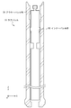
- FIG. 2A is a cross-sectional view showing a configuration example of the core barrel 10 provided at the distal end portion of the drill string 11 used in the wireline recovery method.
- the core barrel 10 shown in FIG. 2A has a two-layer structure, and has an outer barrel portion 30 on the outer side and an inner barrel portion 50 on the inner side.
- the outer barrel portion 30 has a cylindrical shape, and the inner barrel portion 50 is movable in the longitudinal direction of the core barrel 10 ( ⁇ Z direction of coordinates shown in FIG. 2A). *
- FIG. 2A a cross-sectional view of the outer barrel portion 30 is shown, and a side view of the inner barrel portion 50 is schematically shown.
- the outer barrel portion 30 is provided at the distal end of the drill string 11. *
- FIG. 2B is a cross-sectional view illustrating a configuration example of the outer barrel portion 30 in the core barrel 10 illustrated in FIG. 2A.
- the outer barrel portion 30 shown in FIG. 2B includes a core bit 31, a near bit sub 32, a drill collar sub 33, a landing sub 34, a head sub 35, a landing ring 36, and a latch portion 37.
- the core bit 31 is provided at the distal end of the outer barrel portion 30.
- a near bit sub 32 is connected to the upper end of the core bit 31.
- a drill collar sub 33 is connected to the upper end portion of the near bit sub 32.
- a landing sub 34 is connected to the upper end of the drill collar sub 33.
- a head sub 35 is connected to an upper end portion of the landing sub 34.
- the landing ring 36 is provided in the vicinity of the opening on the upper end side of the inner wall of the drill collar sub 33.
- the latch portion 37 includes a space provided by boring the inner wall of the landing sub 34.
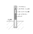
- FIG. 2C is a diagram showing a configuration example of the inner barrel portion 50 in more detail in the core barrel 10 shown in FIG. 2A.
- 2C has an inner tube 51, a core liner 52, a length adjusting mechanism 53, a swivel mechanism 54, a landing mechanism 55, a latch mechanism 56, and a fishing neck 57.
- the length adjusting mechanism 53 has a lock bolt 58. *
- the inner tube 51 is provided at the distal end of the inner barrel portion 50.
- a core liner 52 is provided inside the inner tube 51.
- a length adjusting mechanism 53 is provided on the upper end side of the inner tube 51.
- a swivel mechanism 54 is provided on the upper end side of the length adjusting mechanism 53.
- a landing mechanism 55 is provided on the upper end side of the swivel mechanism 54.
- a latch mechanism 56 is provided on the upper end portion side of the landing mechanism 55.
- a fishing neck 57 is provided on the upper end side of the latch mechanism 56. *
- the fishing neck 57 removably connects the inner barrel portion 50 to a wire line extending from the excavation rig 12.
- the excavation rig 12 controls the wire line to attach and detach the wire line and the fishing neck 57.
- the latch mechanism 56 fixes the inner barrel portion 50 to the outer barrel portion 30 by fitting into the latch portion 37.
- the rotational movement of the outer barrel portion 30 is transmitted to the inner barrel portion 50.
- the latch mechanism 56 is released from the engagement with the latch portion 37 when the inner barrel portion 50 is recovered by the excavation rig 12 via the wire line.
- the landing mechanism 55 adjusts the positional relationship between the inner barrel portion 50 and the outer barrel portion 30 in the longitudinal direction of the drill string 11.
- the outer diameter of the landing mechanism 55 is larger than the inner diameter of the landing ring 36.
- the lower surface of the landing mechanism 55 is placed on the upper surface of the landing ring 36, whereby the inner barrel portion 50 and the outer barrel portion 30. May be determined.
- the swivel mechanism 54 rotates the core liner 52 disposed on the distal side of the swivel mechanism as the outer barrel portion 30 rotates so that the core being collected is not twisted with respect to the excavated formation. It is provided for the purpose of preventing it.
- the swivel mechanism 54 includes an outer portion connected to the upper end side of the inner barrel portion 50, an inner portion connected to the lower end side, and a bearing provided between the outer portion and the inner portion. And have. Due to the presence of the swivel mechanism 54, the rotational movement of the outer barrel portion 30 is not transmitted to the components disposed below the swivel mechanism 54 in the inner barrel portion 50. *
- the length adjusting mechanism 53 is provided to adjust the overall length of the inner barrel portion 50.
- the length adjusting mechanism 53 includes an inner portion connected to the upper end side of the inner barrel portion 50, an outer portion connected to the lower end side, and a lock bolt 58 connecting the inner portion and the outer portion.
- Each of the inner part and the outer part has a plurality of holes through which the lock bolts 58 are passed.
- the length of the inner barrel part 50 can be adjusted by appropriately selecting a hole through which the lock bolt 58 is passed. *
- the inner tube 51 supports the core liner 52 inside thereof.
- the core liner 52 stores the core to be collected.
- the inner tube 51 preferably has a core catcher and a core lifter (not shown).
- the core catcher and the core lifter separate the core to be collected from the formation.
- the core catcher and the core lifter support the core separated from the formation 16 and prevent its fall. Only one of the core catcher and the core lifter may be used. *
- the outer barrel portion 30 and the inner barrel portion 50 shown in FIGS. 2A to 2C are called rotary core barrels and are used when the formation 16 to be collected is relatively hard. When the formation 16 to be collected is relatively soft, an inner barrel portion 50 having another configuration may be used. *
- FIG. 3A to FIG. 3C are diagrams showing each stage of an example of a core collection method using the drill string 11 shown in FIG. 2A to FIG. 2C. *
- the drill string 11 is extended toward the formation 16 where the sample is to be collected, and the inner barrel portion 50 is lowered toward the outer barrel portion 30 through the inside of the drill string 11.
- the opening of the core bit 31 provided at the distal end of the outer barrel portion 30 and the opening of the core liner 52 provided at the distal end of the inner barrel portion 50 overlap with each other in the excavation progress direction of the drill string 11.
- the drill string traveling direction of the drill string 11 coincides with the longitudinal direction of the drill string 11 and also coincides with the rotation axis direction of the drill string 11. *
- the drill string 11 rotates around the rotation axis and advances through the formation 16. At this time, a part of the formation 16 enters the inside of the core liner 52 through the opening of the core bit 31.
- the excavation rig 12 extends the wire line into the outer barrel portion 30 and connects it to the fishing neck 57 of the inner barrel portion 50, and pulls up the inner barrel portion 50 together with the wire line.
- a part of the formation 16 contained in the core liner 52 is separated from the formation 16 and supported by the core catcher and the core lifter and collected as the core 40 of the formation sample.
- the outer diameter of the casing pipe that can be inserted into the excavation hole 17 is equal to the outer diameter of the core bit 31 excavating the excavation hole 17, so that the excavation hole 17 reinforced with the casing pipe can be further excavated.
- the core bit 31 having a smaller outer diameter is required.
- the excavation hole 17 dug by the core bit 31 having a smaller outer diameter is reinforced by another thinner casing pipe. By repeating such steps, deeper excavation becomes possible.
- FIG. 4 is a partial cross-sectional view showing an example of a core collection technique in which a casing pipe is combined with the drill string 11 shown in FIGS. 2A to 2C. *
- the cross-sectional view shown in FIG. 4 includes the formation 16, the drill string 11, the first casing pipe 71, the second casing pipe 72, the third casing pipe 73, and the fourth casing pipe 74. *
- the first casing pipe 71 to the fourth casing pipe 74 are cylindrical structures having different thicknesses and lengths.
- the outer diameter of the first casing pipe 71 is the largest, the outer diameter of the second casing pipe 72 is the next largest, the outer diameter of the third casing pipe 73 is the next largest, and the outer diameter of the fourth casing pipe 74 is The thinnest.
- the first casing pipe 71 is the shortest, the second casing pipe 72 is the next shortest, the third casing pipe 73 is the next shortest, and the fourth casing pipe 74 is the longest. *
- the first casing pipe 71 to the fourth casing pipe 74 are arranged concentrically when viewed from directly above the excavation hole 17 and are buried in the formation 16.
- the upper end portion may be located on the surface of the formation 16.
- the depth at which excavation is possible is improved, while the thickness (outer diameter) of the usable core bit 31 is gradually reduced. Therefore, the outer diameter and inner diameter of the usable drill string 11 are also gradually reduced.
- This embodiment proposes the structure which can suppress the reduction
- FIG. 5A is a cross-sectional view illustrating a configuration example of the outer barrel portion 30 using the float valve sub according to the present embodiment.
- the outer barrel portion 30 shown in FIG. 5A is equivalent to the outer barrel portion 30 shown in FIGS. 2A to 2C with the addition of the float valve sub 2 according to the present embodiment.
- the float valve sub 2 is disposed between the drill collar sub 33 and the near bit sub 32, and the inner tube 51 passes through the inside thereof. *
- the float valve sub 2 according to the present embodiment may be disposed at another location of the outer barrel portion 30.
- the float valve sub 2 according to the present embodiment may be disposed between the core bit 31 and the near bit sub 32.
- the float valve sub 2 may be disposed between the landing sub 34 and the drill collar sub 33.
- each sub including the float valve sub 2 has as high rotational symmetry as possible with respect to the rotation axis of the drill string 11.
- each sub desirably has as high rotational symmetry as possible in order to realize the molding and processing more easily and with higher accuracy.
- rotating bodies such as circles, disks, cylinders, and cylinders appear in various parts in the following description. However, these rotating bodies are not limited to geometrically strict circles, disks, cylinders, cylinders, and the like, but are realistic enough to prevent stable rotation of the drill string 1 and assembly of each sub. Variations within the range may be included.
- FIG. 5B is a partial cross-sectional view showing the connection relationship of the float valve sub 2 according to the present invention with another sub. *
- the float valve sub 2 shown in FIG. 5B has an outer barrel assembly 100 as an outer cylinder assembly and a float valve assembly 200.
- the float valve assembly 200 is disposed inside the outer barrel assembly 100.
- FIG. 5B shows a cross-sectional view of the outer barrel assembly 100. *
- the float valve sub 2 shown in FIG. 5B has an upper sub 300 connected to the upper end side thereof. Further, the float valve sub 2 shown in FIG. 5B has a lower sub 500 connected to the lower end side thereof.
- a taper screw having excellent water tightness.
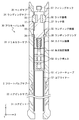
- FIG. 6 is a cross-sectional view showing a configuration example of the outer barrel assembly 100 in the float valve sub 2 according to the present embodiment. *
- the outer barrel assembly 100 as the outer cylinder assembly is preferably formed by processing a single member from the viewpoint of strength and water tightness.
- the outer barrel assembly 100 includes an outer barrel first part 110, an outer barrel second part 120, and an outer barrel intermediate part 130. *
- the outer barrel first portion 110 is the proximal end of the outer barrel assembly 100.
- the outer barrel second portion 120 is the distal end of the outer barrel assembly 100.
- the outer barrel intermediate portion 130 is disposed between the outer barrel first portion 110 and the outer barrel second portion 120.
- the outer barrel first portion 110 includes an outer barrel first connecting portion 111 and an outer barrel first receiving portion 112. A space inside the outer barrel first portion 110 is referred to as an outer barrel first opening 101. *
- the outer barrel first connection part 111 is connected to the lower end side connection part of the upper sub 300.
- a tapered female screw is formed inside the outer barrel first connecting portion 111, and this is fitted with a tapered male screw formed outside the lower end side connecting portion of the upper sub 300.
- the inner peripheral surface of the outer barrel first receiving portion 112 has a shape complementary to the upper end portion (the outer peripheral surface of the upper end portion) of the float valve assembly 200, and receives the upper end portion of the float valve assembly 200. And support.
- the outer barrel first receiving portion 112 has a shape that allows the entire float valve assembly 200 to pass to the outer barrel second receiving portion 122 when the float valve assembly 200 is attached to the outer barrel assembly 100.
- the outer barrel second portion 120 includes an outer barrel second connecting portion 121 and an outer barrel second receiving portion 122.
- the space inside the outer barrel second portion 120 is referred to as the outer barrel second opening 102. *
- the outer barrel second connection part 121 is connected to the upper end side connection part of the lower sub 500.
- a tapered male screw is formed on the outer side of the outer barrel second connecting portion 121, and this is fitted with the tapered female screw formed on the inner side of the upper end side connecting portion of the lower sub 500.
- the inner peripheral surface of the outer barrel second receiving portion 122 has a shape complementary to the lower end portion (outer peripheral surface of the lower end portion) of the float valve assembly 200 on the inner peripheral surface thereof. Receive and support the lower end of the assembly 200.
- the outer barrel second receiving portion 122 has such a shape that the float valve assembly 200 does not pass and does not fall to the lower sub-side of the outer barrel assembly 100.
- the minimum inner diameter DO2 of the outer barrel second portion 120 is smaller than the minimum inner diameter DO1 of the outer barrel first portion 110.
- the minimum inner diameter DO2 is smaller than the maximum outer diameter of the float valve assembly 200 that allows at least the inner tube 51 to penetrate the inside. *
- the outer barrel first opening 101 is connected to the upper side of this space.
- the outer barrel second opening 102 is connected to the lower side of this space.
- the annular recess 103 may be formed by a method such as boring the inner wall of the outer barrel assembly 100.
- the annular recess 103 is provided to receive a flapper lid protruding from the cylindrical portion of the float valve assembly 200.
- the inner diameter DO3 of the annular recess 103 is larger than the minimum inner diameter DO1 of the outer barrel first portion 110.
- the inner diameter at the boundary with the outer barrel first portion 110 on the upper side of the outer barrel intermediate portion 130 is equal to the inner diameter D01 of the outer barrel first receiving portion 112.
- the inner diameter DO3 of the annular recess 103 of the outer barrel intermediate portion 130 is larger than the inner diameter DO1 of the outer barrel first receiving portion 112.
- the inner diameter at the boundary with the outer barrel second portion 120 on the lower side of the outer barrel intermediate portion 130 is equal to the inner diameter D01 of the outer barrel second receiving portion 122.
- the inner diameter DO3 of the annular recess 103 of the outer barrel intermediate portion 130 is larger than the inner diameter DO1 of the outer barrel second receiving portion 122.
- the inner diameter at the boundary between the outer barrel intermediate portion 130 and the outer barrel second portion 120 is the same as the inner diameter D01 of the outer barrel first receiving portion 112, but the former is the latter. It is also possible to make it smaller.
- the minimum wall thickness of the drill pipe of the drill string 11 is expressed as Tmin.
- the drill pipe is an outer wall portion of the drill string 11 on the side of the drilling rig 12 from the rotary core barrel, and has a function of transmitting rotational motion from the drilling rig 12 to the rotary core barrel.
- the strength required for the outer barrel assembly 100 that is a part of the structure constituting the drill string 11 can be any of the outer barrel assemblies 100. Even in the portion, the thickness is guaranteed if the thickness is equal to or greater than the minimum thickness Tmin.
- the thickness T is preferably equal to or greater than the minimum thickness Tmin.
- the material of the outer barrel assembly 100 may be changed to a material having higher strength.
- FIG. 7A is a diagram illustrating a state in which the flapper lid 230 is in the first position in one configuration example of the float valve assembly 200 according to the present embodiment.
- FIG. 7B is a diagram showing a state in which the flapper lid 230 is in the second position in one configuration example of the float valve assembly 200 according to the present embodiment.
- FIG. 7C is a side view of the float valve assembly 200 in the state shown in FIG. 7B. 7A and 7B, a part of the outer wall is shown as a cross-sectional view in order to explain the inside of the float valve assembly 200. *
- FIG. 8A shows the flapper lid 230 of the float valve assembly 200 shown in FIGS. 7A-7C.
- FIG. 8B is a cross-sectional view of the flapper lid 230 shown in FIG. 8A along the cross-sectional line AA.
- FIG. 8C is a cross-sectional view of the flapper lid 230 shown in FIG. 8A along the cross-sectional line BB. *
- the float valve assembly 200 shown in FIGS. 7A to 7C includes a float valve body 210, a flapper lid 230, a hinge 240, a biasing member 250, a sealing member 224, a retainer 225, and a fixing sealing member. 211 and 212. *
- the float valve body 210 shown in FIGS. 7A to 7C includes an upper float valve first end portion 201, a lower float valve second end portion 202, and a float valve intermediate portion 203.
- the float valve intermediate portion 203 is disposed between the float valve first end portion 201 and the float valve second end portion 202.
- the float valve body 210 may be formed by assembling the float valve first end portion 201, the float valve second end portion 202, and the float valve intermediate portion 203 that are separately formed.
- the float valve first end portion 201 includes a body side hinge support portion 213, a body side biasing member support portion 214, and a float valve first opening portion 221.
- the float valve second end 202 has a float valve second opening 222.
- the float valve intermediate portion 203 has a side opening 223. *
- the flapper lid 230 shown in FIGS. 7A to 7C and FIGS. 8A to 8C has a flat surface portion 231, an inner tube guide 232, a side end portion 233, a lid side hinge support portion 234, and a lid side biasing member support. Part 235. *
- FIGS. 7A to 7C and FIGS. 8A to 8C The connection relationships of the components shown in FIGS. 7A to 7C and FIGS. 8A to 8C will be described. *
- the float valve first end 201 has a cylindrical shape.
- the retainer 225 also has a cylindrical shape, and is fitted inside the float valve first end 201.
- the sealing member 224 is made of an elastic material and has an annular shape, and is disposed between the float valve first end 201 and the retainer 225. However, the sealing sealing member 224 has an annular end surface exposed to the space inside the float valve body 210.
- the assembly of the float valve first end portion 201, the retainer 225, and the sealing member 224 for sealing also has a cylindrical shape, and the space inside thereof is called a float valve first opening 221. At this time, the sealing member 224 for sealing is arranged so that the exposed portion surrounds the lower opening surface of the float valve first opening 221.
- the float valve first opening 221 has a size and shape that allows the inner tube 51 to pass through the inside thereof.
- the inner diameter of the float valve first opening 221 is DF2.
- DF2 is strictly the inner diameter of the retainer 225.
- the fixing sealing members 211 and 212 each have an annular shape and are arranged so as to surround the outer periphery of the float valve first end 201.
- the float valve first end portion 201 may have a groove on the outer periphery thereof in order to position the fixing sealing members 211 and 212.
- the fixing sealing members 211 and 212 can be realized by a configuration different from the above.
- a groove may be provided in the surface of the float valve first end 201 that contacts the upper sub 300, and the sealing member 224 for sealing may be disposed in this groove.
- the float valve second end portion 202 has a cylindrical shape, and a space inside the float valve second end portion 202 is referred to as a float valve second opening 222.
- the float valve second opening 222 has a size and shape that allows the inner tube 51 to pass through the inside thereof.
- the inner diameter of the float valve second opening 222 is the same as DF2 as the inner diameter of the float valve first opening 221.
- the inner diameter of the float valve first opening 221 and the inner diameter of the float valve second opening 222 may not necessarily be the same as long as the inner tube 51 can penetrate. *
- the float valve intermediate portion 203 has a cylindrical shape, and a float valve first end portion 201 is connected to an upper end portion thereof, and a float valve second end portion 202 is connected to a lower end portion thereof. Is connected.
- the space inside the float valve intermediate portion 203 is connected to the float valve first opening 221 on the upper side, and connected to the float valve second opening 222 on the lower side.
- Side opening 223 is provided on the side surface of the float valve middle part.
- the side opening 223 is wide enough to allow the flapper lid 230 to pass when moving between the first position and the second position.
- the float valve first end 201 and the flapper lid 230 are connected via a hinge 240.
- the hinge 240 has a cylindrical shape and penetrates the body side hinge support portion 213 and the lid side hinge support portion 234 in its longitudinal direction.
- it is desirable that the hinge 24 is fixed to the body side hinge support portion 213 or the lid side hinge support portion 234 by screwing or the like so that the hinge 24 does not fall off.
- the flapper lid 230 can move between a first position and a second position by rotating around a rotation axis set in the longitudinal direction of the hinge 240.
- the first position is a position where the flapper lid 230 is in close contact with the sealing member 224 and closes the float valve first opening 221 (flow path).
- the second position is a retracted position where the flapper lid 230 releases the flow path of the float valve first opening 221 and does not interfere with the inner tube 51 passing through the float valve assembly.
- the second position is, for example, a position where the entire flapper lid 230 does not overlap the float valve first opening 221 (or the float valve second opening 222) when viewed in the longitudinal direction of the outer barrel assembly 100. *
- the urging member 250 urges the flapper lid 230 toward the first position.
- the urging member 250 is a coiled torsion spring, and the coil portion is disposed around the hinge 240, one end of which is in contact with the body side urging member support 214, and the other end. Contacts the lid-side biasing member support 235.
- a load is applied from the biasing member 250 to the surrounding float valve body 210 so that one end of the biasing member 250 does not come off. Indented in the direction.
- a load is applied from the biasing member 250 to the surrounding flapper lid 230 so that the other end of the biasing member 250 does not come off. Indented in the direction.
- the float valve assembly 200 When the float valve assembly 200 is mounted inside the outer barrel assembly 100, the float valve first end 201 is received and fixed by the outer barrel first receiving portion 112, and the float valve second end 202 is fixed to the outer barrel assembly 100. It is received and supported by the barrel second receiving portion 122. At this time, the float valve second opening 222 is connected to the outer barrel second opening 102.
- the fixing sealing members 211 and 212 seal the float valve first end portion 201 and the outer barrel first receiving portion 112 in a liquid-tight manner.
- DF1 is substantially equal to the minimum inner diameter DO1 of the outer barrel first portion 110, but is preferably equal to or less than DO1.
- the float valve first opening 221 is connected to the lower opening of the upper sub 300.
- the float valve assembly 200 is fixed on the upper side by connection with the upper sub 300.
- the inner tube 51 can pass through the upper sub 300, the float valve first opening 221, the float valve second opening 222, and the outer barrel second opening 102.
- the flapper lid 230 has a flat plane portion 231 at least in the peripheral region of the main surface thereof.
- the flat surface portion 231 contacts the sealing member 224 when the flapper lid 230 moves to the first position.
- the flapper lid 230 closes the flow path of the float valve first opening 221.
- the flapper lid 230 In this state, even if a fluid flows into the drill string 1 from a portion below the float valve sub 2, it does not leak to the upper side of the float valve sub 2 and can prevent a violence.
- the inventor conducted an experiment in which water pressure was applied from the float valve second opening side in the first state of the float valve sub 2 according to the present embodiment.
- the float valve sub 2 having an inner diameter of 98.5 mm was about 20 It was confirmed that durability up to megapascal pressure was obtained.
- This experimental result is merely an example, and does not limit the scope of rights of the present invention.
- the flapper lid 230 moves to the second position, a part of the flapper lid 230 protrudes outside the float valve body 210 through the side opening 223.
- This protruding portion is referred to as a side end portion 233 for ease of explanation.
- the side end 233 has a size and a shape that can be accommodated in the annular recess 103 of the outer barrel assembly 100.
- the inner tube guide 232 included in the flapper lid 230 has a curved surface similar to the outer peripheral surface of the float valve second opening 222 (the inner peripheral surface of the float valve second end 202). ing. Since the inner peripheral surface of the float valve second end portion 202 has a curved surface that is complementary to the side surface of the inner tube 51 that is a cylindrical member, the curved surface of the inner tube guide 232 is also connected to the side surface of the inner tube 51. Complementary shape. Due to this curved surface, the inner tube guide 232 allows the inner tube 51 to be more stably inserted and removed when the flapper lid 230 is in the second position. *
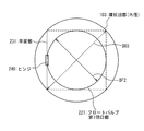
- FIG. 9 is a diagram showing a geometric relationship between the inner diameter DO3 of the annular recess 103 according to the present embodiment and the diameter DF2 of the float valve first opening 221.
- the size thereof needs to be at least equal to or larger than the diameter DF2 of the float valve first opening portion 221.
- a square diagonal line in which the inner diameter DO3 of the annular recess 103 circumscribes a circle having a diameter DF2 is used. Need longer.
- the length DO3 needs to be not less than the square root of 2 times the length DF2.
- the square of the length DO3 needs to be at least twice the square of the length DF2.
- the minimum value of the length DO3 is obtained as described above.
- the maximum value of the length DO3 depends on the strength required for the float valve sub 2 as described above. That is, when the minimum value of the thickness of the side wall portion of the outer barrel assembly 100 that satisfies the required strength is set as Tmin1 and the outer diameter of the outer barrel assembly 100 is set as DO4, the maximum value of the length DO3 is set to be between DO4 and Tmin1. It is equal to the difference with 2 times. Therefore, the numerical limitation related to the length DO3 can be expressed by the following mathematical formula. DO4-2 ⁇ Tmin1 ⁇ DO3> DF2 ⁇ ⁇ 2
- the bare hole without casing satisfies the condition of “geological pressure ⁇ mud water pressure ⁇ geological fracture pressure”, but the geological pressure rises as it digs, so it is necessary to increase the mud pressure accordingly. There is. If you dig too much without the casing, the muddy water pressure will exceed the formation destruction pressure in the upper part of the bare hole, and the muddy water will destroy the formation and the formation will collapse.
- the riser drilling system prevents collapse by casing before it happens. As a result, in the riser excavation system, the depth at which excavation is possible is dramatically improved compared to a so-called riserless excavation system that does not use such a technique. *
- the muddy water used in the riser drilling system requires appropriate adjustments physically and chemically.
- the muddy water adjusted in this way pumps up the mud generated by excavating the formation 16 and the surrounding seawater to the drilling rig 12 by the riser pipe, and adjusts the characteristics thereof by the mud adjusting device mounted on the drilling rig 12. Is generated.
- the adjusted muddy water is sent to the bottom of the drilling hole 17 through the inside of the drill string 11.
- FIG. 10 is a diagram illustrating a configuration example of a coring system using a riser excavation system.
- FIG. 10 is equivalent to a coring system using the riser-less excavation system shown in FIG. 1 to which a riser pipe 19 and an ejection prevention device 20 are added.
- illustration is abbreviate
- the riser pipe 19 is provided around the drill string 11 and extends from the seabed 15 to the drilling rig 12.
- the seabed 15 is provided with an ejection preventing device 20 that connects the excavation hole 17 and the riser pipe 19.
- the float valve sub 2 according to the present invention can be easily applied to the riser excavation system.
- the shape of the annular recess 103 is a rotating body centered on the rotation axis of the drill string 11 has been described so far.
- This description considers the possibility that the float valve assembly 200 rotates with respect to the outer barrel assembly 100 when the annular recess 103 is formed by a lathe process or when the upper sub 300 is attached or detached.
- the annular recess 103 is not necessarily required to have the shape of a rotating body as long as the function of receiving the flapper lid 230 protruding from the cylindrical portion of the float valve assembly 200 can be realized. Further, it may be a concave portion having other shapes such as a cut portion and a cut portion.
Abstract
ドリルストリングの外筒アセンブリの内側に、フロートバルブの蓋を受け入れる拡張部、削り込み部、切り込み部などの凹部を設ける。これにより、ドリルストリングにフロートバルブを設けるにあたって、ドリルストリングの内径を広げ、より細いドリルストリングでより大きい直径のコアの採取を可能とする。
Description
本発明は、ドリルストリングに用いるフロートバルブサブに関し、例えば、ボトムホール・アセンブリの内側にフロートバルブアセンブリを着脱可能に設けたフロートバルブサブに好適に利用できるものである。
地層のサンプルコアを採取する技術が知られている。当該技術では、例えば、ドリルストリングと呼ばれる筒状構造物の端部円周上にドリルビットが設けられている。ドリルストリングは、回転などにより、地層内に侵入する。その後、ドリルストリングを地層から抜き出すことで、ドリルストリングの内側から円柱状の地層サンプルが採取される。このように採取された地層サンプルを解析することで、地層の構造や空隙率などの物理特性をより詳細に知ることが可能となる。この技術は、例えば油ガス層評価や地震に係る研究への寄与などが期待されている。
ドリルストリングで地層を掘削する際、地層流体が坑井内に流入するキックや暴墳と呼ばれる現象が発生する可能性がある。例えば、ドリルストリングの先端が達した先に地下水脈、油ガス層等の液層があった場合に、地層の間隙圧によっては地層流体がドリルビットから逆流しドリルストリングの内側を通り、船上もしくは地上へ噴出し、掘削の継続が困難になる可能性が考えられる。このようなキック・暴墳が発生しそうな場合には、これを適切に防止する防墳装置を、ドリルストリングの内側に予め設け坑井抑制(ウェルコントロール)対策を図ることが望ましい。
上記に関連して、特許文献1および特許文献2には、フラッパ型フロートバルブの発明が開示されている。これらの発明では、いずれの場合も、フラッパ型の蓋を用いるフロートバルブがドリルストリングの内側に設けられている。
掘削作業の観点からは、ドリルストリングの外径をより細くしたい。その一方で、地層解析の観点からは、より大きい直径の地層サンプルを採取するために、ドリルストリングの内径をより広げたい。しかし、従来技術によるフラッパ型フロートバルブでは、フラッパ型の蓋をドリルストリングの内部に設けた結果、ドリルストリングのフロートバルブを設置した部分の最大外径に対するフロートバルブの最小内径の比率が大幅に低下している。この問題は、後述する2層構造のドリルストリングではより顕著になる。その他の課題と新規な特徴は、本明細書の記述および添付図面から明らかになるであろう。
一実施の形態によれば、フロートバルブサブ2は、アウターバレルアセンブリと、フロートバルブアセンブリとを有する。ここで、フロートバルブアセンブリは、アウターバレルアセンブリの内側に、着脱可能に配置される。このフロートバルブアセンブリは、第1端部と、第2端部と、フロートバルブ中間部と、蓋部とを有する。ここで、第1端部と、第2端部とは、それぞれ、筒型の形状を有する。フロートバルブ中間部は、第1端部および第2端部の間に配置される。蓋部は、第1端部に取り付けられており、第1位置および第2位置の間で回動自在である。ここで、蓋部は、第1位置においては第1端部の流路を閉鎖し、第2位置においては第1端部の流路としてのフロートバルブ第1開口部を解放する。フロートバルブ中間部は、蓋部の一部が通過可能な側方開口を有する。アウターバレルアセンブリは、第1部分と、第2部分と、アウターバレル中間部とを有する。
ここで、第1部分は、第1端部を受け入れ、第1端部の外周面と相補的な内周面形状を有する。第2部分は、第2端部を受け入れ、第2端部の外周面と相補的な内周面形状を有する。アウターバレル中間部は、第1部分と、第2部分との間に配置される。アウターバレル中間部は、第2位置にある蓋部を受け入れ可能な凹部を有する。ここで、第1部分の最小内径は、第2部分の最小内径よりも大きく、かつ、環状凹部の内径は、第1部分の最小内径よりも大きい。
前記一実施の形態によれば、フラッパ型フロートバルブをドリルストリング内に設置した際の、ドリルストリングのフロートバルブを設置した部分の最大外径に対する、フロートバルブの最小内径の比率を向上させることが出来る。
添付図面を参照して、本発明によるフロートバルブサブを実施するための形態を以下に説明する。
海底の地層からサンプルを採取するコアリング技術について説明する。図1は、海底を掘削するコアリングシステムの一構成例を示す図である。ここで、コアリングシステムとは、ボトムホール・アセンブリ1の一種である。図1に示した例では、まず、掘削したい海底15の直上の海面14に掘削リグ12を用意する。掘削リグ12は、GPS(Global Positioning System:グローバルポジショニングシステム)衛星18などを利用して、自身の位置を掘削位置の直上に保持し続けることが望ましい。掘削リグ12は、ドリルストリング11を継ぎ足しては海13に降ろす工程を繰り返す。ドリルストリング11の先端が海底15下の地層16内に到達すると(掘削孔17を参照)、掘削リグ12はドリルストリング11を制御して海底15の地層16から地層サンプルとしてのコアを採取する。
しかしながら、海面14から海底15までの距離は数千メートルに達する場合があり、このような場合にも1本のコアを採取するたびにドリルストリング11の全体を昇降していては作業効率が悪い。そこで、ドリルストリング11による掘削を開始したらその後は揚管せずに、ドリルストリングのアウターバレル部の内側に挿入されるインナーバレル部を用いて、コアを掘削リグ12に連続的に回収する技術が知られている。このような技術の1つに、ワイヤライン回収方式がある。
なお、図1に示したコアリングシステムは、海底掘削のみならず、陸上における地層掘削にも使用可能である。
図2Aは、ワイヤライン回収方式で用いるドリルストリング11の遠位端部に設けられたコアバレル10の一構成例を示す断面図である。図2Aに示したコアバレル10は2層構造であり、外側にアウターバレル部30を有し、内側にインナーバレル部50を有している。アウターバレル部30は筒状であり、その内側をインナーバレル部50が、コアバレル10の長手方向(図2Aに示した座標の±Z方向)に移動可能である。
なお、図2Aでは、アウターバレル部30についてはその断面図を示し、インナーバレル部50についてはその側面図を概略的に示している。アウターバレル部30はドリルストリング11の遠位端に設けられている。
図2Bは、図2Aに示したコアバレル10のうち、アウターバレル部30の一構成例を示す断面図である。図2Bに示したアウターバレル部30は、コアビット31と、ニアビットサブ32と、ドリルカラーサブ33と、ランディングサブ34と、ヘッドサブ35と、ランディングリング36と、ラッチ部37とを有している。
コアビット31は、アウターバレル部30の遠位端に設けられている。コアビット31の上端部には、ニアビットサブ32が接続されている。ニアビットサブ32の上端部には、ドリルカラーサブ33が接続されている。ドリルカラーサブ33の上端部には、ランディングサブ34が接続されている。ランディングサブ34の上端部には、ヘッドサブ35が接続されている。ランディングリング36は、ドリルカラーサブ33の内壁の、上端側開口部の付近に設けられている。ラッチ部37は、ランディングサブ34の内壁を中ぐりして設けられた空間を含む。
図2Cは、図2Aに示したコアバレル10のうち、インナーバレル部50の一構成例をより詳細に示す図である。図2Cに示したインナーバレル部50は、インナーチューブ51と、コアライナー52と、長さ調節機構53と、スイベル機構54と、ランディング機構55と、ラッチ機構56と、フィッシングネック57とを有している。ここで、長さ調節機構53は、ロックボルト58を有している。
インナーチューブ51は、インナーバレル部50の遠位端に設けられている。インナーチューブ51の内側には、コアライナー52が設けられている。インナーチューブ51の上端部側には、長さ調節機構53が設けられている。長さ調節機構53の上端部側には、スイベル機構54が設けられている。スイベル機構54の上端部側には、ランディング機構55が設けられている。ランディング機構55の上端部側には、ラッチ機構56が設けられている。ラッチ機構56の上端部側には、フィッシングネック57が設けられている。
フィッシングネック57は、掘削リグ12から伸びるワイヤラインに、インナーバレル部50を着脱可能に接続する。ワイヤラインおよびフィッシングネック57の着脱は、掘削リグ12がワイヤラインを制御して行う。
ラッチ機構56は、ラッチ部37に嵌合することによってインナーバレル部50をアウターバレル部30に固定する。ラッチ機構56がアウターバレル部30に固定されると、アウターバレル部30の回転運動がインナーバレル部50に伝達される。また、ラッチ機構56は、インナーバレル部50がワイヤラインを介して掘削リグ12に回収される際には、ラッチ部37との嵌合が解除される。
ランディング機構55は、インナーバレル部50と、アウターバレル部30との、ドリルストリング11の長手方向にお
ける位置関係を調節する。図2Cに示した例では、ランディング機構55の外径は、ランディングリング36の内径よりも大きい。ここで、インナーバレル部50が掘削リグ12からアウターバレル部30の端部まで落下する際、ランディング機構55の下面がランディングリング36の上面に載ることによって、インナーバレル部50と、アウターバレル部30との位置関係が決定しても良い。
ける位置関係を調節する。図2Cに示した例では、ランディング機構55の外径は、ランディングリング36の内径よりも大きい。ここで、インナーバレル部50が掘削リグ12からアウターバレル部30の端部まで落下する際、ランディング機構55の下面がランディングリング36の上面に載ることによって、インナーバレル部50と、アウターバレル部30との位置関係が決定しても良い。
スイベル機構54は、採取途中のコアが、掘削される地層に対して捩じれないように、スイベル機構の遠位側に配置されているコアライナー52を、アウターバレル部30の回転運動に伴って回転しないようにする目的で設けられている。図2Cに示した例では、スイベル機構54は、インナーバレル部50の上端側に接続される外側部分と、下端側に接続される内側部分と、外側部分および内側部分の間に設けられたベアリングとを有する。スイベル機構54の存在によって、アウターバレル部30の回転運動は、インナーバレル部50のうち、スイベル機構54より下側に配置される構成要素には伝達されない。
長さ調節機構53は、インナーバレル部50の全長を調節するために設けられている。長さ調節機構53は、インナーバレル部50の上端側に接続される内側部分と、下端側に接続される外側部分と、内側部分および外側部分を接続するロックボルト58とを有する。内側部分および外側部分のそれぞれは、ロックボルト58を通す穴を複数有している。長さ調節機構53の内側部分および外側部分のそれぞれにおいて、ロックボルト58を通す穴を適宜に選択することによって、インナーバレル部50の長さを調節することが出来る。
インナーチューブ51は、その内側にコアライナー52を支持している。コアライナー52は、採取するコアを格納する。インナーチューブ51は、図示しないコアキャッチャーおよびコアリフターを有していることが望ましい。ここで、コアキャッチャーおよびコアリフターは、採取されるべきコアを地層から切り離す。また、コアキャッチャーおよびコアリフターは地層16から切り離したコアを支持してその落下を防止する。なお、コアキャッチャーおよびコアリフターは、どちらか一方だけを用いても良い。
なお、図2A~図2Cに示したアウターバレル部30およびインナーバレル部50は、ロータリーコアバレルと呼ばれ、採取したい地層16が比較的硬い場合に用いられる。採取したい地層16が比較的柔らかい場合は、他の構成によるインナーバレル部50を用いても良い。
図3A~図3Cは、図2A~図2Cに示したドリルストリング11を用いたコア採取の手法の一例の各段階を示す図である。
図3Aに示した第1段階では、サンプルを採取したい地層16に向けてドリルストリング11を延ばし、ドリルストリング11の内部を通してインナーバレル部50をアウターバレル部30に向けて降ろす。このとき、アウターバレル部30の先端に設けられたコアビット31の開口と、インナーバレル部50の先端に設けられたコアライナー52の開口とが、ドリルストリング11の掘削進行方向に重なり合うことが望ましい。なお、ドリルストリング11の掘削進行方向は、ドリルストリング11の長手方向に一致し、また、ドリルストリング11の回転軸方向にも一致する。
図3Bに示した第2段階では、ドリルストリング11が回転軸まわりに回転して地層16を掘り進む。このとき、地層16の一部が、コアビット31の開口を介してコアライナー52の内部に入る。
図3Cに示した第3段階では、掘削リグ12が、ワイヤラインをアウターバレル部30の内部に伸ばしてインナーバレル部50のフィッシングネック57に接続し、ワイヤライン共々、インナーバレル部50を引き上げる。このとき、コアライナー52の内部に入っている地層16の一部は、コアキャッチャーおよびコアリフターによって地層16からの切り離しおよび支持をされ、地層サンプルのコア40として採取される。
その後、掘削リグ12に引き上げられたインナーバレル部50からコア40が取り出されると、第1段階から第3段階までの各段階が繰り返される。こうすることで、アウターバレル部30を含むドリルストリング11を揚菅することなく、コア40を連続的に採取することが可能となる。
より深く掘削を行うために、ケーシングパイプを用いる手法が知られている。ドリルストリング11を用いて地層16を掘り進めていくと、掘削孔17を囲む地層が崩れるなどして、ドリルストリング11の回転や掘進が妨げられ、掘削の継続が困難になる可能性がある。これを防ぐために、ある程度の深度まで掘削した後に、ドリルストリング11を防護するケーシングパイプで掘削孔17の内壁を補強することが考えられる。
掘削孔17に挿入可能なケーシングパイプの外径は、この掘削孔17を掘削したコアビット31の外径と同等であるので、ケーシングパイプで補強された掘削孔17をさらに掘り進めるためには、別のより外径の小さいコアビット31が必要となる。また、より外径の小さいコアビット31で掘り進めた掘削孔17は、別のより細いケーシングパイプで補強されることになる。このような段階を繰り返すことで、より深い掘削が可能となる。
図4は、図2A~図2Cに示したドリルストリング11にケーシングパイプを組み合わせたコア採取の手法の一例を示す部分断面図である。
図4に示した断面図は、地層16と、ドリルストリング11と、第1ケーシングパイプ71と、第2ケーシングパイプ72と、第3ケーシングパイプ73と、第4ケーシングパイプ74とを含んでいる。
第1ケーシングパイプ71~第4ケーシングパイプ74は、それぞれ、太さおよび長さが互いに異なる円筒状の構造物である。第1ケーシングパイプ71の外径が最も太く、第2ケーシングパイプ72の外径がその次に太く、第3ケーシングパイプ73の外径はさらにその次に太く、第4ケーシングパイプ74の外径が最も細い。また、第1ケーシングパイプ71が最も短く、第2ケーシングパイプ72がその次に短く、第3ケーシングパイプ73はさらにその次に短く、第4ケーシングパイプ74が最も長い。
第1ケーシングパイプ71~第4ケーシングパイプ74は、掘削孔17の直上から見ると同心円状に配置されて、地層16に埋められている。第1ケーシングパイプ71~第4ケーシングパイプ74のそれぞれにおいて、上端部は地層16の表面に位置していても良い。
複数のケーシングパイプを用いることで、掘削可能な深度が向上する半面、使用可能なコアビット31の太さ(外径)は段階的に細くなる。したがって、使用可能なドリルストリング11の外径および内径も段階的に小さくなってしまう。
さらに、暴墳を防ぐフロートバルブをドリルストリング11の内部に設けると、ドリルストリング11の部分的な内径が、さらに減少してしまい、したがってドリルストリング11の外径に対する内径の比率がさらに減少してしまうことが考えられる。
(第1実施形態) 本実施形態では、ドリルストリングの内部にフロートバルブを設けても、外径に対する内径の比率の減少を抑制出来る構成を提案する。
図5Aは、本実施形態によるフロートバルブサブを用いるアウターバレル部30の一構成例を示す断面図である。図5Aに示したアウターバレル部30は、図2A~図2Cに示したアウターバレル部30に、本実施形態によるフロートバルブサブ2を追加したものに等しい。フロートバルブサブ2は、ドリルカラーサブ33と、ニアビットサブ32との間に配置されており、その内側をインナーチューブ51が通過している。
なお、本実施形態によるフロートバルブサブ2は、アウターバレル部30の別の場所に配置されても良い。例えば、本実施形態によるフロートバルブサブ2を、コアビット31と、ニアビットサブ32との間に配置しても良い。あるいは、フロートバルブサブ2を、ランディングサブ34と、ドリルカラーサブ33との間に配置しても良い。さらなる変形例としては、インナーチューブ51を取り外さない、いわゆるコンベンショナル型のロータリーコアバレルにも、本実施形態によるフロートバルブサブ2を設けることが可能である。
図5Aに示したアウターバレル部30に含まれるその他の構成要素については、図2A~図2Cの場合と同様であるので、さらなる詳細な説明を省略する。
なお、ドリルストリング11が安定的に回転するためには、フロートバルブサブ2を含む各サブの形状が、ドリルストリング11の回転軸に対して、なるべく高い回転対称性を有することが望ましい。また、各サブは、その成形や加工を、より容易に、かつ、より高精度で実現するためにも、やはりなるべく高い回転対称性を有することが望ましい。このような理由により、以降の説明では様々な部分に円、円盤、円柱、円筒などの回転体が登場する。ただし、これらの回転体は、幾何学的に厳密な円、円盤、円柱、円筒などとは限らず、ドリルストリング1の安定的な回転や、各サブの組み立てなどを妨げない程度の現実的な範囲内での変形を含んでも構わない。
図5Bは、本発明によるフロートバルブサブ2の、他のサブとの接続関係を示す部分断面図である。
図5Bに示したフロートバルブサブ2は、外筒アセンブリとしてのアウターバレルアセンブリ100と、フロートバルブアセンブリ200とを有する。フロートバルブアセンブリ200は、アウターバレルアセンブリ100の内部に配置されている。図5Bではアウターバレルアセンブリ100の断面図を示している。
図5Bに示したフロートバルブサブ2は、その上端側に、上側サブ300が接続されている。また、図5Bに示したフロートバルブサブ2は、その下端側に、下側サブ500が接続されている。上側サブ300およびフロートバルブサブ2の接続と、フロートバルブサブ2および下側サブ500との接続とには、例えば、水密性に優れるテーパーねじを用いることが望ましい。
図6は、本実施形態によるフロートバルブサブ2のうち、アウターバレルアセンブリ100の一構成例を示す断面図である。
外筒アセンブリとしてのアウターバレルアセンブリ100は、強度や水密性の観点から、単一の部材を加工して形成することが望ましい。アウターバレルアセンブリ100は、アウターバレル第1部分110と、アウターバレル第2部分120と、アウターバレル中間部130とを備える。
アウターバレル第1部分110は、アウターバレルアセンブリ100の近位側の端部である。アウターバレル第2部分120は、アウターバレルアセンブリ100の遠位側の端部である。アウターバレル中間部130は、アウターバレル第1部分110と、アウターバレル第2部分120との間に配置されている。
アウターバレル第1部分110は、アウターバレル第1接続部111と、アウターバレル第1受け入れ部112とを備える。また、アウターバレル第1部分110の内側の空間を、アウターバレル第1開口部101と呼ぶ。
アウターバレル第1接続部111は、上側サブ300の下端側接続部と接続される。図5Bおよび図6に示した構成例では、アウターバレル第1接続部111の内側にテーパー雌ねじが形成されており、これが上側サブ300の下端側接続部の外側に形成されたテーパー雄ねじと嵌合する。
アウターバレル第1受け入れ部112の内周面は、フロートバルブアセンブリ200の上側端部(上側端部の外周面)と相補的な形状を有しており、フロートバルブアセンブリ200の上側端部を受け入れて支持する。なお、アウターバレル第1受け入れ部112は、フロートバルブアセンブリ200をアウターバレルアセンブリ100に装着する際に、フロートバルブアセンブリ200の全体がアウターバレル第2受け入れ部122まで通過出来る形状を有している。
同様に、アウターバレル第2部分120は、アウターバレル第2接続部121と、アウターバレル第2受け入れ部122とを備える。また、アウターバレル第2部分120の内側の空間を、アウターバレル第2開口部102と呼ぶ。
アウターバレル第2接続部121は、下側サブ500の上端側接続部と接続される。図5Bおよび図6に示した構成例では、アウターバレル第2接続部121の外側にテーパー雄ねじが形成されており、これが下側サブ500の上端側接続部の内側に形成されたテーパー雌ねじと嵌合する。
アウターバレル第2受け入れ部122の内周面は、その内周面に、フロートバルブアセンブリ200の下側端部と(下側端部の外周面)相補的な形状を有しており、フロートバルブアセンブリ200の下側端部を受け入れて支持する。なお、アウターバレル第2受け入れ部122は、フロートバルブアセンブリ200が通り過ぎてアウターバレルアセンブリ100の下側サブ側に落下しないような形状を有している。このような形状の一例として、図6に示した構成例では、アウターバレル第2部分120の最小内径DO2が、アウターバレル第1部分110の最小内径DO1よりも小さい。なお、この最小内径DO2は、少なくともインナーチューブ51が内側を貫通出来る、フロートバルブアセンブリ200の最大外径よりも小さな寸法である。
アウターバレル中間部130の内側には、フロートバルブアセンブリ200を受け入れるための空間がある。この空間の上側には、アウターバレル第1開口部101が繋がっている。この空間の下側には、アウターバレル第2開口部102が繋がっている。この空間の外周、かつ、アウターバレル中間部130の内周面には、環状凹部103がある。環状凹部103は、アウターバレルアセンブリ100の内壁を中ぐり加工するなどの方法で形成しても良い。環状凹部103は、後述するように、フロートバルブアセンブリ200の筒形状部からはみ出るフラッパ蓋を受け入れるために設けられる。環状凹部103の内径DO3は、アウターバレル第1部分110の最小内径DO1よりも大きい。
アウターバレル中間部130の上側の、アウターバレル第1部分110との境界における内径は、アウターバレル第1受け入れ部112の内径D01に等しい。そして、アウターバレル中間部130の環状凹部103の内径DO3は、アウターバレル第1受け入れ部112の内径DO1よりも大きい。ここで、アウターバレル中間部130の上側内周面において、内径がDO1からDO3に連続的に変化する領域があっても良い。
同様に、アウターバレル中間部130の下側の、アウターバレル第2部分120との境界における内径は、アウターバレル第2受け入れ部122の内径D01に等しい。そして、アウターバレル中間部130の環状凹部103の内径DO3は、アウターバレル第2受け入れ部122の内径DO1よりも大きい。ここで、アウターバレル中間部130の下側内周面において、内径がDO3からDO1に連続的に変化する領域があっても良い。
なお、本実施形態では、アウターバレル中間部130の下側の、アウターバレル第2部分120との境界における内径を、アウターバレル第1受け入れ部112の内径D01と同サイズとしているが、前者を後者より小さくすることも可能である。
ドリルストリング11のドリルパイプの最小肉厚をTminと表記する。ここで、ドリルパイプとは、ドリルストリング11のうち、ロータリーコアバレルより掘削リグ12側の部分の、外壁部分であって、掘削リグ12からロータリーコアバレルまで回転運動を伝達する機能などを担う。一般的にアウターバレルアセンブリ100の外径はドリルパイプの外径より大きいため、ドリルストリング11を構成する構造体の一部であるアウターバレルアセンブリ100に要求される強度は、アウターバレルアセンブリ100のどの部分においても、その厚さが最小厚さTmin以上であれば保障される。したがって、アウターバレルアセンブリ100の側壁のうち、環状凹部103の厚さをTと置くとき、厚さTは最小厚さTmin以上であることが望ましい。なお、厚さTとして、最小厚さTmin以上の値を確保出来ない場合は、アウターバレルアセンブリ100の材質を、より強度の高い材質に変更しても良い。
図7Aは、本実施形態によるフロートバルブアセンブリ200の一構成例の、フラッパ蓋230が第1位置にある状態を示す図である。図7Bは、本実施形態よるフロートバルブアセンブリ200一構成例の、フラッパ蓋230が第2位置にある状態を示す図である。図7Cは、図7Bに示した状態のフロートバルブアセンブリ200の側面図である。図7Aおよび図7Bにおいては、フロートバルブアセンブリ200の内部を説明するために、外壁の一部を断面図として示している。
図8Aは、図7A~図7Cに示したフロートバルブアセンブリ200のフラッパ蓋230を示す図である。図8Bは、図8Aに示したフラッパ蓋230の、断面線A-Aによる断面図である。図8Cは、図8Aに示したフラッパ蓋230の、断面線B-Bによる断面図である。
図7A~図7Cに示したフロートバルブアセンブリ200は、フロートバルブボディ210と、フラッパ蓋230と、ヒンジ240と、付勢部材250と、密閉用シーリング部材224と、リテーナ225と、固定用シーリング部材211、212とを有している。
図7A~図7Cに示したフロートバルブボディ210は、上側のフロートバルブ第1端部201と、下側のフロートバルブ第2端部202と、フロートバルブ中間部203とを備える。ここで、フロートバルブ中間部203は、フロートバルブ第1端部201と、フロートバルブ第2端部202との間に配置されている。
なお、別々に形成したフロートバルブ第1端部201と、フロートバルブ第2端部202と、フロートバルブ中間部203とを組み立てることによってフロートバルブボディ210を形成しても良い。
フロートバルブ第1端部201は、ボディ側ヒンジ支持部213と、ボディ側付勢部材支持部214と、フロートバルブ第1開口部221とを有している。フロートバルブ第2端部202は、フロートバルブ第2開口部222を有している。フロートバルブ中間部203は、側方開口223を有している。
図7A~図7Cおよび図8A~図8Cに示したフラッパ蓋230は、平面部231と、インナーチューブガイド232と、側端部233と、蓋側ヒンジ支持部234と、蓋側付勢部材支持部235とを有する。
図7A~図7Cおよび図8A~図8Cに示した各構成要素の接続関係について説明する。
フロートバルブ第1端部201は、筒型の形状を有している。リテーナ225も筒型の形状を有しており、フロートバルブ第1端部201の内側に嵌合されている。密閉用シーリング部材224は、弾性材質で環状の形状を有しており、フロートバルブ第1端部201と、リテーナ225との間に配置されている。ただし、密閉用シーリング部材224は、その環状の端面が、フロートバルブボディ210の内側の空間に向けて露出している。フロートバルブ第1端部201と、リテーナ225と、密閉用シーリング部材224との集合体も筒状の形状を有しており、その内側の空間をフロートバルブ第1開口部221と呼ぶ。このとき、密閉用シーリング部材224は、その露出部分が、フロートバルブ第1開口部221の、下側の開口面を囲むように配置されている。なお、フロートバルブ第1開口部221は、その内側をインナーチューブ51が貫通出来るサイズおよび形状を有する。ここで、フロートバルブ第1開口部221の内径をDF2とする。なお、本実施形態において、DF2は、厳密にはリテーナ225の内径である。
固定用シーリング部材211、212は、それぞれ、環状の形状を有しており、フロートバルブ第1端部201の外周を囲むようにして配置されている。ここで、フロートバルブ第1端部201は、固定用シーリング部材211、212の位置を位置決めするために、その外周に溝を有していても良い。
なお、固定用シーリング部材211、212は、上記とは異なる構成でも実現可能である。例えば、フロートバルブ第1端部201の、上側サブ300と接する面に溝を設け、この溝に密閉用シーリング部材224を配置しても良い。
フロートバルブ第2端部202は、筒状の形状を有しており、その内側の空間をフロートバルブ第2開口部222と呼ぶ。フロートバルブ第2開口部222は、その内側をインナーチューブ51が貫通出来るサイズおよび形状を有する。ここで、本実施形態では、フロートバルブ第2開口部222の内径を、フロートバルブ第1開口部221の内径と同じDF2とする。なお、フロートバルブ第1開口部221の内径と、フロートバルブ第2開口部222の内径とは、インナーチューブ51が貫通さえ出来れば、必ずしも同じでなくても良い。
フロートバルブ中間部203は、筒型の形状を有しており、その上側端部にはフロートバルブ第1端部201が接続されており、その下側端部にはフロートバルブ第2端部202が接続されている。フロートバルブ中間部203の内側の空間は、上側においてはフロートバルブ第1開口部221に繋がっており、下側においてはフロートバルブ第2開口部222に繋がっている。
フロートバルブ中間部の側面には側方開口223が設けられている。側方開口223は、フラッパ蓋230が第1位置および第2位置の間で移動する際に通過できる程度に広い。
フロートバルブ第1端部201と、フラッパ蓋230とは、ヒンジ240を介して接続されている。ヒンジ240は、円柱状の形状を有し、ボディ側ヒンジ支持部213と、蓋側ヒンジ支持部234とを、自身の長手方向に貫通している。ここで、ヒンジ24が抜け落ちないように、ヒンジ24は、ボディ側ヒンジ支持部213または蓋側ヒンジ支持部234に対してねじ止めするなどして固定されることが望ましい。
フラッパ蓋230は、ヒンジ240の長手方向に設定される回転軸の周囲を回転して第1位置および第2位置の間を移動することが出来る。ここで、第1位置とは、フラッパ蓋230が密閉用シーリング部材224に密着してフロートバルブ第1開口部221(流路)を閉鎖する位置である。また、第2位置とは、フラッパ蓋230がフロートバルブ第1開口部221の流路を解放し、かつ、フロートバルブアセンブリを通過するインナーチューブ51に干渉しない退避位置である。第2位置とは、例えば、フラッパ蓋230の全体が、アウターバレルアセンブリ100の長手方向に見て、フロートバルブ第1開口部221(またはフロートバルブ第2開口部222)に重ならない位置である。
付勢部材250は、フラッパ蓋230を第1位置に向けて付勢する。本実施形態において、付勢部材250はコイル状のねじりばねであって、そのコイル部分はヒンジ240の周囲に配置されており、その一端はボディ側付勢部材支持部214に接触し、その他端は蓋側付勢部材支持部235に接触する。ここで、本実施形態によるボディ側付勢部材支持部214は、付勢部材250の一端が外れないように、周囲のフロートバルブボディ210の部分に対して、付勢部材250から負荷が加えられる方向に、凹んでいる。同様に、本実施形態による蓋側付勢部材支持部235は、付勢部材250の他端が外れないように、周囲のフラッパ蓋230の部分に対して、付勢部材250から負荷が加えられる方向に、凹んでいる。
本実施形態によるフロートバルブサブ2の、組み立てに係る動作について説明する。
フロートバルブアセンブリ200がアウターバレルアセンブリ100の内側に装着される際、フロートバルブ第1端部201がアウターバレル第1受け入れ部112によって受け入れられて固定され、また、フロートバルブ第2端部202がアウターバレル第2受け入れ部122によって受け入れられて支持される。このとき、フロートバルブ第2開口部222は、アウターバレル第2開口部102に繋がる。
フロートバルブアセンブリ200がアウターバレルアセンブリ100の内側に装着された際、固定用シーリング部材211、212は、フロートバルブ第1端部201と、アウターバレル第1受け入れ部112とを、液密にシールする。ここで、フロートバルブアセンブリ200の外径をDF1とするとき、DF1はアウターバレル第1部分110の最小内径DO1にほぼ等しく、ただしDO1以下であることが望ましい。
フロートバルブアセンブリ200を装着したアウターバレルアセンブリ100に上側サブ300を装着する際、フロートバルブ第1開口部221は、上側サブ300の下側開口部に繋がる。このとき、フロートバルブアセンブリ200は、上側サブ300との接続によって、その上側を固定される。この状態において、インナーチューブ51は、上側サブ300と、フロートバルブ第1開口部221と、フロートバルブ第2開口部222と、アウターバレル第2開口部102とを通過出来る。
本実施形態によるフロートバルブサブ2の、フラッパ蓋230がフロートバルブ第1開口部221を閉鎖する動作について説明する。
インナーバレル部50が掘削リグ12によって引き上げられるなどして、インナーチューブ51がフロートバルブボディ210の内部から退出すると、付勢部材250の働きによって、フラッパ蓋230が図7Aに示す第1位置に移動する。
フラッパ蓋230は、少なくともその主面の周辺領域に、平坦な平面部231を有している。平面部231は、フラッパ蓋230が第1位置に移動した際、密閉用シーリング部材224と接触する。そして、フラッパ蓋230は、フロートバルブ第1開口部221の流路を閉鎖する。その結果、ドリルストリング1の内部空間のうち、フロートバルブサブ2より上側の部分と下側の部分とは、フラッパ蓋230によって隔離される。この状態において、ドリルストリング1の内部にフロートバルブサブ2より下側の部分から流体が流入しても、フロートバルブサブ2より上側には漏れず、暴墳を防ぐことが出来る。
発明者は、本実施形態によるフロートバルブサブ2の第1状態においてフロートバルブ第2開口部側から水圧を印加する実験を行った結果、98.5ミリメートルの内径を有するフロートバルブサブ2が約20メガパスカルの圧力までの耐久性が得られることを確認した。なお、この実験結果はあくまでも一例であって、本発明の権利範囲を限定するものではない。
本実施形態によるフロートバルブサブ2の、フラッパ蓋230がフロートバルブ第1開口部221を解放する動作について説明する。
インナーバレル部50がアウターバレル部30の端部まで挿入されるなどして、インナーチューブ51がフロートバルブボディ210の内部に進入する際、インナーチューブ51がフラッパ蓋230を押す力が付勢部材250の力を上回り、フラッパ蓋230は図7Bに示す第2位置に移動する。
フラッパ蓋230は、第2位置に移動するとき、その一部が側方開口223を通ってフロートバルブボディ210の外部にはみ出る。このはみ出る部分を、説明を簡単にするために、側端部233と呼ぶ。図8Cに示すように、側端部233は、アウターバレルアセンブリ100の環状凹部103の内部に収まる寸法および形状を有している。
図8Cに示したように、フラッパ蓋230が備えるインナーチューブガイド232は、フロートバルブ第2開口部222の外周面(フロートバルブ第2端部202の内周面)と同様の湾曲面を有している。フロートバルブ第2端部202の内周面は、円柱状部材であるインナーチューブ51の側面と相補的な湾曲面を有しているので、インナーチューブガイド232の湾曲面もインナーチューブ51の側面と相補的な形状である。この湾曲面により、インナーチューブガイド232は、フラッパ蓋230が第2位置にある際に、インナーチューブ51のより安定的な挿抜を可能にする。
本実施形態による環状凹部103の内径について説明する。
図9は、本実施形態による環状凹部103の内径DO3と、フロートバルブ第1開口部221の径DF2との幾何学的な関係を示す図である。まず、フラッパ蓋230の平面部231に注目すると、その寸法は、最低でもフロートバルブ第1開口部221の径DF2以上である必要がある。次に、第2位置に移動したフラッパ蓋230を、インナーチューブ51に干渉しないように環状凹部103に格納するためには、環状凹部103の内径DO3が、直径DF2の円に外接する正方形の対角線より長い必要がある。すなわち、長さDO3は、長さDF2の、2の平方根倍以上である必要がある。言い換えれば、長さDO3の二乗は、長さDF2の二乗の2倍以上である必要がある。厳密には、ヒンジ240の太さや、フラッパ蓋230の厚みなども勘案する必要があるので、長さDO3およびDF2に係る上記の関係は、以下の数式で表すことが出来る。
DO3>DF2×√2
または、
DO3×DO3>2×DF2×DF2
DO3>DF2×√2
または、
DO3×DO3>2×DF2×DF2
長さDO3の最低値は上記のように求まる。なお、長さDO3の最高値は、上述のとおり、フロートバルブサブ2に求められる強度に依存する。すなわち、求められる強度を満たすアウターバレルアセンブリ100の側壁部分の厚さの最低値をTmin1と置き、アウターバレルアセンブリ100の外径をDO4と置くとき、長さDO3の最大値は、DO4とTmin1の2倍との差に等しい。したがって、長さDO3に係る数値限定は、以下の数式で表すことが出来る。
DO4-2×Tmin1≧DO3>DF2×√2
DO4-2×Tmin1≧DO3>DF2×√2
(第2実施形態)
第1実施形態では、構成要素を簡略化するために、いわゆるライザーレス掘削システムを前提とした説明を行った。ここでは、第2実施形態としていわゆるライザー掘削システムを前提とした説明を行う。
第1実施形態では、構成要素を簡略化するために、いわゆるライザーレス掘削システムを前提とした説明を行った。ここでは、第2実施形態としていわゆるライザー掘削システムを前提とした説明を行う。
ライザー掘削システムでは、掘削孔17を泥水で満たすことで、「地層圧<泥水圧<地層破壊圧」の条件を満たし、掘削孔17を囲む内壁が崩壊することを防ぐ。
なお、ケーシングしていない裸孔では、「地層圧<泥水圧<地層破壊圧」の条件を満たしているものの、掘り進めるにつれて地層圧が上昇していくため、これに合わせて泥水圧も上げる必要がある。ケーシングなしで掘り進み過ぎると、そのうち裸孔の上部では泥水圧が地層破壊圧を上回り、泥水が地層を破壊して地層が崩れてきてしまう。ライザー掘削システムでは、そうなる前にケーシングを行うことで崩壊を防いでいる。その結果、ライザー掘削システムでは、このような手法を用いないいわゆるライザーレス掘削システムと比較して、掘削可能な深度が飛躍的に向上している。
ライザー掘削システムで用いる泥水は、物理的に、かつ、化学的に、適宜な調整を必要とする。このように調整された泥水は、地層16を掘削して生じる泥と、周囲の海水とを、ライザーパイプによって掘削リグ12まで汲み上げ、掘削リグ12に搭載された泥水調整装置でその特性を調整することで生成される。調整された泥水は、ドリルストリング11の内側を通って掘削孔17の底部まで送られる。
図10は、ライザー掘削システムを用いたコアリングシステムの一構成例を示す図である。図10は、図1に示したライザーレス掘削システムを用いたコアリングシステムに、ライザーパイプ19および噴出防止装置20を追加したものと同等である。なお、掘削リグ12に搭載している泥水調整装置については、図示を省略する。
図10に示した構成例では、ライザーパイプ19はドリルストリング11の周囲に設けられており、海底15から掘削リグ12まで延びている。なお、海底15には、掘削孔17と、ライザーパイプ19とを接続する噴出防止装置20が設けられている。
泥水は、掘削リグ12から掘削孔17の底部まで移動する際に、インナーバレル部50を挿入していない状態のドリルストリング11の内部を通過する。このとき、フロートバルブサブ2の内部も通過することになるが、フラッパ蓋230は上側から進入する泥水に押されればフロートバルブ第1開口部221を解放する方向に移動出来るので、泥水の通過の妨げにはならない。
このように、本発明によるフロートバルブサブ2は、ライザー掘削システムにも容易に適用可能である。
以上、発明者によってなされた発明を実施の形態に基づき具体的に説明したが、本発明は前記実施の形態に限定されるものではなく、その要旨を逸脱しない範囲で種々変更可能であることはいうまでもない。また、前記実施の形態に説明したそれぞれの特徴は、技術的に矛盾しない範囲で自由に組み合わせることが可能である。
例えば、環状凹部103について、これまでの説明ではその形状がドリルストリング11の回転軸を中心とする回転体である場合について説明した。この説明は、環状凹部103を旋盤加工によって形成したり、上側サブ300を着脱する際などにフロートバルブアセンブリ200がアウターバレルアセンブリ100に対して回転したりする可能性を考慮したものである。しかしながら、環状凹部103は、前述のとおり、フロートバルブアセンブリ200の筒形状部からはみ出るフラッパ蓋230を受け入れる機能さえ実現出来れば、実際には回転体の形状を有する必要までは無く、任意の拡張部、削り込み部、切り込み部など、その他の形状を有する凹部であっても構わない。
1 ボトムホール・アセンブリ 2 フロートバルブサブ 10 コアバレル 11 ドリルストリング 12 掘削リグ 13 海 14 海面 15 海底 16 地層 17 掘削孔 18 GPS衛星 19 ライザーパイプ 20 暴墳防止装置 30 アウターバレル部 31 コアビット 32 ニアビットサブ 33 ドリルカラーサブ 34 ランディングサブ 35 ヘッドサブ 36 ランディングリング 37 ラッチ部 40 コア 50 インナーバレル部 51 インナーチューブ 52 コアライナー 53 長さ調節機構 54 スイベル機構 55 ランディング機構 56 ラッチ機構 57 フィッシングネック 58 ロックボルト 71 第1ケーシングパイプ 72 第2ケーシングパイプ 73 第3ケーシングパイプ 74 第4ケーシングパイプ 100 アウターバレルアセンブリ 101 アウターバレル第1開口部 102 アウターバレル第2開口部 103 環状凹部 110 アウターバレル第1部分 111 アウターバレル第1接続部 112 アウターバレル第1受け入れ部 120 アウターバレル第2部分 121 アウターバレル第2接続部 122 アウターバレル第2受け入れ部 130 アウターバレル中間部 200 フロートバルブアセンブリ 201 フロートバルブ第1端部 202 フロートバルブ第2端部 203 フロートバルブ中間部 210 フロートバルブボディ 211 固定用シーリング部材 212 固定用シーリング部材 213 ボディ側ヒンジ支持部 214 ボディ側付勢部材支持部 221 フロートバルブ第1開口部 222 フロートバルブ第2開口部 223 側方開口 224 密閉用シーリング部材 225 リテーナ 230 フラッパ蓋 231 平面部 232 インナーチューブガイド 233 側端部 234 蓋側ヒンジ支持部 235 蓋側付勢部材支持部 240 ヒンジ 250 付勢部材 300 上側サブ 500 下側サブ
Claims (4)
- 外筒アセンブリと、
前記外筒アセンブリの内側に着脱可能に配置されるフロートバルブアセンブリと
を具備し、
前記フロートバルブアセンブリは、
筒形状を有する第1端部と、
筒形状を有する第2端部と、
前記第1端部と前記第2端部との間に配置されるバルブアセンブリ中間部と、
前記第1端部に取り付けられた蓋部と
を備え、
前記蓋部は、前記第1端部の流路を閉鎖する第1位置と、前記第1端部の前記流路を開放する第2位置との間で、回動自在であり、
前記バルブアセンブリ中間部は、前記蓋部の一部が通過可能な側方開口を備え、
前記外筒アセンブリは、
前記第1端部を受け入れ、前記第1端部の外周面と相補的な内周面形状を有する第1部分と、
前記第2端部を受け入れ、前記第2端部の外周面と相補的な内周面形状を有する第2部分と、
前記第1部分と前記第2部分との間に配置される外筒アセンブリ中間部と
を備え、
前記外筒アセンブリ中間部は、前記第2位置にある前記蓋部を受け入れ可能な凹部を備え、
前記第1部分の最小内径は、前記第2部分の最小内径よりも大きく、
前記凹部の内径は、前記第1部分の最小内径よりも大きい
フロートバルブサブ。 - 請求項1に記載のフロートバルブサブにおいて、
前記外筒アセンブリ中間部の前記凹部の内径は、前記フロートバルブアセンブリの前記第2端部の内径の、2の平方根倍よりも大きい
フロートバルブサブ。 - 請求項1または2に記載のフロートバルブサブにおいて、
前記蓋部は、前記第1端部の前記流路を閉鎖可能な上面を備え、
前記上面は、前記第1端部の前記流路を通過可能な円柱状部材の側面と相補的な湾曲面を備える
フロートバルブサブ。 - 請求項1乃至3のいずれか一項に記載のフロートバルブサブにおいて、
前記第1端部の内周面上に配置される環状のリテーナと、
前記リテーナと、前記第1端部との間に配置される環状のシール部材とをさらに備え、
前記シール部材は、前記第1位置にある前記蓋部を液密にシールする
フロートバルブサブ。
Priority Applications (2)
| Application Number | Priority Date | Filing Date | Title |
|---|---|---|---|
| EP16827823.2A EP3327248A4 (en) | 2015-07-21 | 2016-07-21 | FLOAT VALVE CONNECTION |
| US15/746,221 US10767446B2 (en) | 2015-07-21 | 2016-07-21 | Float valve sub |
Applications Claiming Priority (2)
| Application Number | Priority Date | Filing Date | Title |
|---|---|---|---|
| JP2015144300A JP6551001B2 (ja) | 2015-07-21 | 2015-07-21 | フロートバルブサブ |
| JP2015-144300 | 2015-07-21 |
Publications (1)
| Publication Number | Publication Date |
|---|---|
| WO2017014263A1 true WO2017014263A1 (ja) | 2017-01-26 |
Family
ID=57835119
Family Applications (1)
| Application Number | Title | Priority Date | Filing Date |
|---|---|---|---|
| PCT/JP2016/071390 WO2017014263A1 (ja) | 2015-07-21 | 2016-07-21 | フロートバルブサブ |
Country Status (4)
| Country | Link |
|---|---|
| US (1) | US10767446B2 (ja) |
| EP (1) | EP3327248A4 (ja) |
| JP (1) | JP6551001B2 (ja) |
| WO (1) | WO2017014263A1 (ja) |
Families Citing this family (18)
| Publication number | Priority date | Publication date | Assignee | Title |
|---|---|---|---|---|
| US11136845B2 (en) * | 2016-12-05 | 2021-10-05 | Flexidrill Limited | Coring apparatus |
| JP6927484B2 (ja) | 2017-02-17 | 2021-09-01 | 国立研究開発法人海洋研究開発機構 | 海底掘削サポートシステム |
| US11199071B2 (en) | 2017-11-20 | 2021-12-14 | Halliburton Energy Services, Inc. | Full bore buoyancy assisted casing system |
| WO2020117229A1 (en) | 2018-12-05 | 2020-06-11 | Halliburton Energy Services, Inc. | Downhole apparatus |
| WO2020131076A1 (en) | 2018-12-20 | 2020-06-25 | Halliburtion Energy Services, Inc. | Buoyancy assist tool |
| WO2020131104A1 (en) | 2018-12-21 | 2020-06-25 | Halliburton Energy Services, Inc. | Buoyancy assist tool |
| US11603736B2 (en) | 2019-04-15 | 2023-03-14 | Halliburton Energy Services, Inc. | Buoyancy assist tool with degradable nose |
| WO2020214154A1 (en) | 2019-04-16 | 2020-10-22 | Halliburton Energy Services, Inc. | Downhole apparatus with degradable plugs |
| WO2020226655A1 (en) | 2019-05-09 | 2020-11-12 | Halliburton Energy Services, Inc. | Downhole apparatus with removable plugs |
| US11499395B2 (en) | 2019-08-26 | 2022-11-15 | Halliburton Energy Services, Inc. | Flapper disk for buoyancy assisted casing equipment |
| US11105166B2 (en) | 2019-08-27 | 2021-08-31 | Halliburton Energy Services, Inc. | Buoyancy assist tool with floating piston |
| US11072990B2 (en) | 2019-10-25 | 2021-07-27 | Halliburton Energy Services, Inc. | Buoyancy assist tool with overlapping membranes |
| US10995583B1 (en) | 2019-10-31 | 2021-05-04 | Halliburton Energy Services, Inc. | Buoyancy assist tool with debris barrier |
| US10989013B1 (en) | 2019-11-20 | 2021-04-27 | Halliburton Energy Services, Inc. | Buoyancy assist tool with center diaphragm debris barrier |
| US11230905B2 (en) | 2019-12-03 | 2022-01-25 | Halliburton Energy Services, Inc. | Buoyancy assist tool with waffle debris barrier |
| US11142994B2 (en) | 2020-02-19 | 2021-10-12 | Halliburton Energy Services, Inc. | Buoyancy assist tool with annular cavity and piston |
| US11359454B2 (en) | 2020-06-02 | 2022-06-14 | Halliburton Energy Services, Inc. | Buoyancy assist tool with annular cavity and piston |
| US11753904B2 (en) * | 2021-05-10 | 2023-09-12 | Baker Hughes Oilfield Operations Llc | Valve having a modular activation system |
Citations (3)
| Publication number | Priority date | Publication date | Assignee | Title |
|---|---|---|---|---|
| US3318387A (en) * | 1964-09-28 | 1967-05-09 | Chevron Res | Drilling method and apparatus |
| US4457376A (en) * | 1982-05-17 | 1984-07-03 | Baker Oil Tools, Inc. | Flapper type safety valve for subterranean wells |
| US6152232A (en) * | 1998-09-08 | 2000-11-28 | Halliburton Energy Services, Inc. | Underbalanced well completion |
Family Cites Families (8)
| Publication number | Priority date | Publication date | Assignee | Title |
|---|---|---|---|---|
| US2162578A (en) | 1937-05-27 | 1939-06-13 | Marcus L Hacker | Core barrel operated float valve |
| US3058534A (en) | 1958-04-29 | 1962-10-16 | Baker Oil Tools Inc | Drill pipe float valves |
| NL103683C (ja) | 1959-05-20 | |||
| US3066693A (en) | 1960-02-18 | 1962-12-04 | Jr Julian S Taylor | Float valve for drill pipe and the like |
| US3446237A (en) | 1967-04-03 | 1969-05-27 | William L Haley | Drill pipe float valve |
| US4691775A (en) * | 1986-03-25 | 1987-09-08 | Dresser Industries, Inc. | Isolation valve with frangible flapper element |
| US8607876B2 (en) | 2011-02-16 | 2013-12-17 | Thrubit, B.V. | Flapper valve |
| AU2013316198B2 (en) | 2012-09-13 | 2017-10-26 | Switchfloat Holdings Limited | Improvements in, or related to, float valve hold open devices and methods therefor |
-
2015
- 2015-07-21 JP JP2015144300A patent/JP6551001B2/ja active Active
-
2016
- 2016-07-21 WO PCT/JP2016/071390 patent/WO2017014263A1/ja active Application Filing
- 2016-07-21 US US15/746,221 patent/US10767446B2/en active Active
- 2016-07-21 EP EP16827823.2A patent/EP3327248A4/en not_active Withdrawn
Patent Citations (3)
| Publication number | Priority date | Publication date | Assignee | Title |
|---|---|---|---|---|
| US3318387A (en) * | 1964-09-28 | 1967-05-09 | Chevron Res | Drilling method and apparatus |
| US4457376A (en) * | 1982-05-17 | 1984-07-03 | Baker Oil Tools, Inc. | Flapper type safety valve for subterranean wells |
| US6152232A (en) * | 1998-09-08 | 2000-11-28 | Halliburton Energy Services, Inc. | Underbalanced well completion |
Non-Patent Citations (1)
| Title |
|---|
| See also references of EP3327248A4 * |
Also Published As
| Publication number | Publication date |
|---|---|
| US20180209245A1 (en) | 2018-07-26 |
| US10767446B2 (en) | 2020-09-08 |
| EP3327248A1 (en) | 2018-05-30 |
| JP6551001B2 (ja) | 2019-07-31 |
| JP2017025553A (ja) | 2017-02-02 |
| EP3327248A4 (en) | 2019-03-27 |
Similar Documents
| Publication | Publication Date | Title |
|---|---|---|
| WO2017014263A1 (ja) | フロートバルブサブ | |
| US9080399B2 (en) | Earth-boring tools including retractable pads, cartridges including retractable pads for such tools, and related methods | |
| US10125559B2 (en) | Core jam indicator for coring tools and coring tools including such core jam indicators | |
| CN102597413B (zh) | 液压锁定稳定器 | |
| CN105637170B (zh) | 定向钻探方法及定向钻探系统 | |
| EP2585672B1 (en) | Fluid partition unit | |
| CN102782248A (zh) | 具有可缩回的可锁从动闩锁机构的岩芯钻井工具 | |
| US11078761B2 (en) | Annular volume filler for perforating gun | |
| US9976413B2 (en) | Pressure locking device for downhole tools | |
| US5119891A (en) | Adaptor for drilling strings with controllable air passage | |
| US11788369B2 (en) | Method and apparatus to recover cores from downhole environments | |
| US11624252B1 (en) | Adjustable mill | |
| US8869915B2 (en) | Systems and methods for sonic subsurface material removal | |
| US8783649B2 (en) | Sleeve valve with permanent end position | |
| CN105745395A (zh) | 利用取芯液填充取芯工具内筒的方法 | |
| US10871051B2 (en) | System and method for drilling a wellbore portion in a subterranean formation | |
| US10975644B2 (en) | Inner barrel assembly for recovery of reservoir fluids from a core sample | |
| US20230167701A1 (en) | Method and apparatus to recover cores from downhole environments | |
| US20230358118A1 (en) | Wellbore protector ram | |
| US11585207B2 (en) | Advanced rapid logging system | |
| US11725475B2 (en) | Drill pipe conveyed permanent bridge plug with integral casing scraper | |
| US20220268115A1 (en) | Reamer / guide interchangeable tubular shoe | |
| US20180216418A1 (en) | Adjustable Hydraulic Coupling For Drilling Tools And Related Methods |
Legal Events
| Date | Code | Title | Description |
|---|---|---|---|
| 121 | Ep: the epo has been informed by wipo that ep was designated in this application |
Ref document number: 16827823 Country of ref document: EP Kind code of ref document: A1 |
|
| WWE | Wipo information: entry into national phase |
Ref document number: 15746221 Country of ref document: US |
|
| NENP | Non-entry into the national phase |
Ref country code: DE |
|
| WWE | Wipo information: entry into national phase |
Ref document number: 2016827823 Country of ref document: EP |