WO2017014138A1 - Image presenting device, optical transmission type head-mounted display, and image presenting method - Google Patents
Image presenting device, optical transmission type head-mounted display, and image presenting method Download PDFInfo
- Publication number
- WO2017014138A1 WO2017014138A1 PCT/JP2016/070806 JP2016070806W WO2017014138A1 WO 2017014138 A1 WO2017014138 A1 WO 2017014138A1 JP 2016070806 W JP2016070806 W JP 2016070806W WO 2017014138 A1 WO2017014138 A1 WO 2017014138A1
- Authority
- WO
- WIPO (PCT)
- Prior art keywords
- image
- display
- virtual
- display surface
- unit
- Prior art date
Links
- 230000003287 optical effect Effects 0.000 title claims description 43
- 238000000034 method Methods 0.000 title claims description 33
- 230000005540 biological transmission Effects 0.000 title description 6
- 230000000007 visual effect Effects 0.000 claims description 2
- 208000013057 hereditary mucoepithelial dysplasia Diseases 0.000 description 25
- 230000000694 effects Effects 0.000 description 12
- 230000014509 gene expression Effects 0.000 description 11
- 238000012986 modification Methods 0.000 description 11
- 230000004048 modification Effects 0.000 description 11
- 238000012545 processing Methods 0.000 description 11
- 238000009877 rendering Methods 0.000 description 11
- 238000010586 diagram Methods 0.000 description 8
- 230000006870 function Effects 0.000 description 7
- 238000004891 communication Methods 0.000 description 6
- 238000006073 displacement reaction Methods 0.000 description 6
- 239000000470 constituent Substances 0.000 description 4
- 238000004590 computer program Methods 0.000 description 3
- 210000003128 head Anatomy 0.000 description 3
- 230000001133 acceleration Effects 0.000 description 2
- 238000003384 imaging method Methods 0.000 description 2
- 206010052143 Ocular discomfort Diseases 0.000 description 1
- 230000003190 augmentative effect Effects 0.000 description 1
- 238000009933 burial Methods 0.000 description 1
- 230000000295 complement effect Effects 0.000 description 1
- 230000007423 decrease Effects 0.000 description 1
- 238000011161 development Methods 0.000 description 1
- 210000004709 eyebrow Anatomy 0.000 description 1
- 238000007654 immersion Methods 0.000 description 1
- 230000001771 impaired effect Effects 0.000 description 1
- 230000010365 information processing Effects 0.000 description 1
- 238000013507 mapping Methods 0.000 description 1
- 229910044991 metal oxide Inorganic materials 0.000 description 1
- 150000004706 metal oxides Chemical class 0.000 description 1
- 230000008447 perception Effects 0.000 description 1
- 239000004065 semiconductor Substances 0.000 description 1
- 239000007787 solid Substances 0.000 description 1
- 230000001131 transforming effect Effects 0.000 description 1
Images


Classifications
-
- G—PHYSICS
- G02—OPTICS
- G02B—OPTICAL ELEMENTS, SYSTEMS OR APPARATUS
- G02B27/00—Optical systems or apparatus not provided for by any of the groups G02B1/00 - G02B26/00, G02B30/00
- G02B27/01—Head-up displays
- G02B27/017—Head mounted
- G02B27/0172—Head mounted characterised by optical features
-
- G—PHYSICS
- G02—OPTICS
- G02B—OPTICAL ELEMENTS, SYSTEMS OR APPARATUS
- G02B27/00—Optical systems or apparatus not provided for by any of the groups G02B1/00 - G02B26/00, G02B30/00
- G02B27/01—Head-up displays
- G02B27/0101—Head-up displays characterised by optical features
- G02B27/0103—Head-up displays characterised by optical features comprising holographic elements
-
- G—PHYSICS
- G02—OPTICS
- G02B—OPTICAL ELEMENTS, SYSTEMS OR APPARATUS
- G02B27/00—Optical systems or apparatus not provided for by any of the groups G02B1/00 - G02B26/00, G02B30/00
- G02B27/01—Head-up displays
- G02B27/017—Head mounted
- G02B27/0176—Head mounted characterised by mechanical features
-
- G—PHYSICS
- G09—EDUCATION; CRYPTOGRAPHY; DISPLAY; ADVERTISING; SEALS
- G09G—ARRANGEMENTS OR CIRCUITS FOR CONTROL OF INDICATING DEVICES USING STATIC MEANS TO PRESENT VARIABLE INFORMATION
- G09G3/00—Control arrangements or circuits, of interest only in connection with visual indicators other than cathode-ray tubes
- G09G3/001—Control arrangements or circuits, of interest only in connection with visual indicators other than cathode-ray tubes using specific devices not provided for in groups G09G3/02 - G09G3/36, e.g. using an intermediate record carrier such as a film slide; Projection systems; Display of non-alphanumerical information, solely or in combination with alphanumerical information, e.g. digital display on projected diapositive as background
- G09G3/003—Control arrangements or circuits, of interest only in connection with visual indicators other than cathode-ray tubes using specific devices not provided for in groups G09G3/02 - G09G3/36, e.g. using an intermediate record carrier such as a film slide; Projection systems; Display of non-alphanumerical information, solely or in combination with alphanumerical information, e.g. digital display on projected diapositive as background to produce spatial visual effects
-
- H—ELECTRICITY
- H04—ELECTRIC COMMUNICATION TECHNIQUE
- H04N—PICTORIAL COMMUNICATION, e.g. TELEVISION
- H04N13/00—Stereoscopic video systems; Multi-view video systems; Details thereof
- H04N13/10—Processing, recording or transmission of stereoscopic or multi-view image signals
- H04N13/106—Processing image signals
- H04N13/128—Adjusting depth or disparity
-
- H—ELECTRICITY
- H04—ELECTRIC COMMUNICATION TECHNIQUE
- H04N—PICTORIAL COMMUNICATION, e.g. TELEVISION
- H04N13/00—Stereoscopic video systems; Multi-view video systems; Details thereof
- H04N13/30—Image reproducers
-
- H—ELECTRICITY
- H04—ELECTRIC COMMUNICATION TECHNIQUE
- H04N—PICTORIAL COMMUNICATION, e.g. TELEVISION
- H04N13/00—Stereoscopic video systems; Multi-view video systems; Details thereof
- H04N13/30—Image reproducers
- H04N13/332—Displays for viewing with the aid of special glasses or head-mounted displays [HMD]
- H04N13/344—Displays for viewing with the aid of special glasses or head-mounted displays [HMD] with head-mounted left-right displays
-
- H—ELECTRICITY
- H04—ELECTRIC COMMUNICATION TECHNIQUE
- H04N—PICTORIAL COMMUNICATION, e.g. TELEVISION
- H04N13/00—Stereoscopic video systems; Multi-view video systems; Details thereof
- H04N13/30—Image reproducers
- H04N13/398—Synchronisation thereof; Control thereof
-
- G—PHYSICS
- G02—OPTICS
- G02B—OPTICAL ELEMENTS, SYSTEMS OR APPARATUS
- G02B27/00—Optical systems or apparatus not provided for by any of the groups G02B1/00 - G02B26/00, G02B30/00
- G02B27/01—Head-up displays
- G02B27/0101—Head-up displays characterised by optical features
- G02B2027/0132—Head-up displays characterised by optical features comprising binocular systems
- G02B2027/0134—Head-up displays characterised by optical features comprising binocular systems of stereoscopic type
-
- G—PHYSICS
- G02—OPTICS
- G02B—OPTICAL ELEMENTS, SYSTEMS OR APPARATUS
- G02B27/00—Optical systems or apparatus not provided for by any of the groups G02B1/00 - G02B26/00, G02B30/00
- G02B27/01—Head-up displays
- G02B27/0101—Head-up displays characterised by optical features
- G02B2027/0138—Head-up displays characterised by optical features comprising image capture systems, e.g. camera
-
- G—PHYSICS
- G02—OPTICS
- G02B—OPTICAL ELEMENTS, SYSTEMS OR APPARATUS
- G02B27/00—Optical systems or apparatus not provided for by any of the groups G02B1/00 - G02B26/00, G02B30/00
- G02B27/01—Head-up displays
- G02B27/0101—Head-up displays characterised by optical features
- G02B2027/014—Head-up displays characterised by optical features comprising information/image processing systems
-
- G—PHYSICS
- G02—OPTICS
- G02B—OPTICAL ELEMENTS, SYSTEMS OR APPARATUS
- G02B27/00—Optical systems or apparatus not provided for by any of the groups G02B1/00 - G02B26/00, G02B30/00
- G02B27/01—Head-up displays
- G02B27/017—Head mounted
- G02B27/0172—Head mounted characterised by optical features
- G02B2027/0174—Head mounted characterised by optical features holographic
-
- G—PHYSICS
- G02—OPTICS
- G02B—OPTICAL ELEMENTS, SYSTEMS OR APPARATUS
- G02B27/00—Optical systems or apparatus not provided for by any of the groups G02B1/00 - G02B26/00, G02B30/00
- G02B27/01—Head-up displays
- G02B27/017—Head mounted
- G02B2027/0178—Eyeglass type
-
- G—PHYSICS
- G02—OPTICS
- G02B—OPTICAL ELEMENTS, SYSTEMS OR APPARATUS
- G02B27/00—Optical systems or apparatus not provided for by any of the groups G02B1/00 - G02B26/00, G02B30/00
- G02B27/01—Head-up displays
- G02B27/0179—Display position adjusting means not related to the information to be displayed
- G02B2027/0187—Display position adjusting means not related to the information to be displayed slaved to motion of at least a part of the body of the user, e.g. head, eye
Definitions
- the present invention relates to a data processing technique, and more particularly to an image presentation device, an optical transmission type head mounted display, and an image presentation method.
- HMD head-mounted displays
- a shielded HMD that completely covers and shields the field of view of the user wearing the HMD and can give a deep immersion to the user who observes the video.
- An optical transmission type HMD has been developed as another type of HMD.
- the optical transmission type HMD uses a holographic element, a half mirror, etc. to show the AR (Augmented Reality) image, which is a virtual 3D image, to the user and to see through the real space outside the HMD to the user. It is an image presentation device that can be presented.
- the present invention has been made on the basis of the above-mentioned recognition of the present inventor, and a main object thereof is to provide a technique for improving the stereoscopic effect of an image presented by the image presenting apparatus.
- an image presentation apparatus includes a display unit that displays an image and a control unit.
- the display unit includes a plurality of display surfaces corresponding to a plurality of pixels in the image to be displayed, and each display surface is configured such that the position in the vertical direction with respect to the display surface can be freely changed. The position of each of the plurality of display surfaces is adjusted based on the depth information of the object included in the image.
- This apparatus includes a display unit that displays an image, an optical element that presents a virtual image of the image displayed on the display unit to the user's field of view, and a control unit.
- the display unit includes a plurality of display surfaces corresponding to a plurality of pixels in the image to be displayed, and each display surface is configured such that the position in the vertical direction with respect to the display surface can be freely changed. By adjusting the position of each of the plurality of display surfaces based on the depth information of the object included in the image, the position of the virtual image presented by the optical element is adjusted in units of pixels.
- Still another aspect of the present invention is an image presentation method.
- This method is a method executed by an image presentation apparatus including a display unit, and the display unit includes a plurality of display surfaces corresponding to a plurality of pixels in an image to be displayed, and each display surface corresponds to the display surface.
- the position in the vertical direction can be changed freely, and the step of adjusting the position of each of the plurality of display surfaces based on the depth information of the object included in the display target image, and the position of each display surface have been adjusted Displaying an image to be displayed on the display unit.
- Still another aspect of the present invention is also an image presentation method.
- This method is a method executed by an image presentation apparatus including a display unit and an optical element, and the display unit includes a plurality of display surfaces corresponding to a plurality of pixels in an image to be displayed, and each display surface is The optical element is configured to be freely changeable in the vertical direction with respect to the display surface, and the optical element presents a virtual image of the image displayed on the display unit in the user's field of view, and the object included in the display target image.
- the stereoscopic effect of the image presented by the image presentation device can be improved.
- FIGS. 6A and 6B are diagrams schematically illustrating a relationship between an object in a virtual three-dimensional space and the object superimposed in the real space. It is a figure explaining the formula of the lens concerning a convex lens.
- FIG. 1 It is a figure which shows typically the optical system with which the image presentation apparatus of 2nd Embodiment is provided. It is a figure which shows the image which a display part should display in order to show the virtual image of the same magnitude
- the light includes information on amplitude (intensity), wavelength (color), and direction (ray direction).
- amplitude and wavelength of light can be expressed, but it is difficult to express the direction of light. For this reason, it has been difficult for a person viewing an image on the display to sufficiently perceive the depth of an object (object) reflected in the image.
- the present inventor considered that if the information on the light beam direction of light can be reproduced on the display, the person who sees the image on the display can be given a perception that is not different from the reality.
- the former has a problem that machine wear and sound are generated due to rotation and reliability is low. Further, the latter has a problem that the resolution is reduced to (1 / viewpoint number) and the load of the drawing process is high.
- a method of displacing the surface of the display in the user's line-of-sight direction for each pixel is proposed.
- the user's line-of-sight direction can be said to be the Z-axis direction and the depth direction.
- first embodiment a plurality of display members that form a screen of a display, and a plurality of pixels in an image to be displayed on the display are displayed.
- a plurality of corresponding display members are moved in a direction perpendicular to the screen of the display.
- second embodiment a method of enlarging with a lens so that the displacement for each pixel is small is proposed. Specifically, the virtual image of the image displayed on the display is presented to the user via the optical element, and the distance to the virtual image perceived by the user is changed for each pixel. According to this method, it is possible to present an image with further improved stereoscopic effect to the user.
- third embodiment an example in which projection mapping is performed on a surface that is dynamically displaced is shown. As will be described later, an HMD is shown as a preferred example of the second and third embodiments.
- FIG. 1 schematically shows an appearance of an image presentation device 100 according to the first embodiment.
- the image presentation device 100 according to the first embodiment is a display device including a screen 102 that displays images actively and autonomously.
- a display device including a screen 102 that displays images actively and autonomously.
- an LED display or an OLED display may be used.
- it may be a display device having a relatively large size such as several tens of inches (eg, a television receiver).
- the display unit 318 configures the screen 102 of the image presentation device 100.
- the left-right direction is the Z axis, that is, the left side surface of the display unit 318 in the figure corresponds to the screen 102 of the image presentation apparatus 100.
- the display unit 318 includes a plurality of display surfaces 326 in an area (the left side surface in the drawing) configuring the screen 102.
- the region constituting the screen 102 is typically a surface that faces the user who views the image presentation device 100, in other words, a surface that is orthogonal to the user's line of sight.
- the plurality of display surfaces 326 correspond to a plurality of pixels in the image to be displayed. In other words, the plurality of display surfaces 326 correspond to a plurality of pixels on the screen 102 of the image presentation device 100.
- the pixels in the image displayed on the display unit 318 in other words, the pixels on the screen 102 and the display surface 326 have a one-to-one correspondence. That is, the display unit 318 (screen 102) is provided with the display surfaces 326 for the number of pixels of the image to be displayed, in other words, the display surfaces 326 for the number of pixels of the screen 102 are provided.
- the display unit 318 (screen 102) is provided with the display surfaces 326 for the number of pixels of the image to be displayed, in other words, the display surfaces 326 for the number of pixels of the screen 102 are provided.
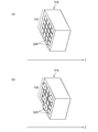
- 2A and 2B 16 display surfaces are shown for the sake of convenience, but in reality, a fine and large amount of display surfaces 326 are provided. For example, (1440 ⁇ 1080) display surfaces 326 are provided. May be provided.
- Each of the plurality of display surfaces 326 is configured such that the position in the vertical direction with respect to the screen 102 (display surface) can be changed.
- the direction perpendicular to the display surface can be said to be the Z-axis direction, that is, the user's line-of-sight direction.
- FIG. 2A shows a state where all the display surfaces 326 are at the reference position (initial position).
- FIG. 2B shows a state in which the positions of some display surfaces 326 protrude forward from the reference position. In other words, FIG. 2B shows a state in which the positions of some display surfaces 326 are close to the user's viewpoint side.
- the display unit 318 of the embodiment includes MEMS (Micro Electro Mechanical Systems).
- the plurality of display surfaces 326 are driven independently from each other by the MEMS microactuator, and the positions of the display surfaces 326 in the Z-axis direction are set independently from each other.
- the position control of the plurality of display surfaces 326 may be realized by a combination of a technique for controlling braille dots in a braille display or a braille printer and MEMS. Moreover, you may implement
- Each display surface 326 corresponding to each pixel includes three primary color light emitting elements and is driven independently from each other by a microactuator.
- a piezoelectric actuator is used as a microactuator.
- the position of each display surface 326 may be adjusted by moving the position of the display surface 326 backward from the reference position (adjusting the display surface 326 away from the user's viewpoint).
- an electrostatic actuator may be used as the microactuator. Piezoelectric actuators and electrostatic actuators have the merit of miniaturization, but electromagnetic actuators and thermal actuators may be used as other modes.
- FIG. 3 is a block diagram illustrating a functional configuration of the image presentation device 100 according to the first embodiment.
- Each block shown in the block diagram of the present specification is realized by various modules mounted in the housing of the image presentation apparatus 100.
- hardware can be realized by an element such as a computer CPU and memory, an electronic circuit, and a mechanical device, and software can be realized by a computer program or the like.
- Draw functional blocks Therefore, those skilled in the art will understand that these functional blocks can be realized in various forms by a combination of hardware and software.
- a computer program including a module corresponding to each block of the control unit 10 in FIG. 3 is stored in a recording medium such as a DVD and distributed, or downloaded from a predetermined server and installed in the image presentation apparatus 100. Also good. Moreover, each function of the control part 10 of FIG. 3 may be exhibited by CPU and GPU of the image presentation apparatus 100 reading the computer program to the main memory, and executing it.
- the image presentation device 100 includes a control unit 10, an image presentation unit 14, and an image storage unit 16.
- the image storage unit 16 is a storage area for storing image data such as still images and moving images (videos) to be presented to the user. It may be realized by various recording media such as a DVD or storage such as an HDD.
- the image storage unit 16 further stores depth information of various objects such as a person, a building, a background, and a landscape shown in the image.
- the depth information is information that reflects a sense of distance that is recognized by the user by looking at the subject when, for example, an image showing the subject is presented to the user. Therefore, as an example of the depth information of the object, the distance from the camera to each object when a plurality of objects are captured is included.
- the depth information of the object may be information indicating an absolute position in the depth direction of each part (for example, a part corresponding to each pixel) of the object, for example, a distance from a predetermined reference position (origin or the like).
- the depth information may be information indicating a relative position between each part of the object, for example, a difference in coordinates, or may be information indicating the front and back of the position (length of distance from the viewpoint).
- depth information is determined in advance for each frame unit image, and a combination of the frame unit image and the depth information is stored in the image storage unit 16 in association with each other.
- an image to be displayed and depth information may be provided to the image presentation apparatus 100 via a broadcast wave or the Internet.
- the control unit 10 of the image presentation device 100 analyzes a statically held or dynamically provided image, and generates a depth information generation unit that generates depth information of each object included in the image. Further, it may be provided.
- the image presentation unit 14 displays the image stored in the image storage unit 16 on the screen 102.
- the image presentation unit 14 includes a display unit 318.
- the control unit 10 executes data processing for presenting an image to the user. Specifically, the control unit 10 determines the positions in the Z-axis direction of the plurality of display surfaces 326 in the display unit 318 in units of pixels in the presentation target image based on the depth information of the object shown in the presentation target image. adjust.
- the control unit 10 includes an image acquisition unit 34, a display surface position determination unit 30, a position control unit 32, and a display control unit 26.
- the image acquisition unit 34 reads the image data stored in the image storage unit 16 at a predetermined rate (such as the refresh rate of the screen 102) and depth information associated with the image data.
- the image acquisition unit 34 outputs the image data to the display control unit 26, and outputs the depth information to the display surface position determination unit 30.
- the image acquisition unit 34 acquires image data or depth information via an antenna or network adapter (not shown). May be.
- the display surface position determination unit 30 determines the position of each of the plurality of display surfaces 326 included in the display unit 318, specifically the position in the Z-axis direction, based on the depth information of each object included in the display target image. In other words, the position of each display surface 326 corresponding to the pixel in each partial area of the display target image is determined.
- the position in the Z-axis direction may be a displacement amount (movement amount) from the reference position.
- the display surface position determination unit 30 includes a first pixel corresponding to a part of an object in the real space or the virtual space that is close to the camera in the real space or the virtual space, and an object that is far from the camera.
- the position of each display surface 326 is determined so that the position of the display surface 326 corresponding to the first pixel is ahead of the position of the display surface 326 corresponding to the second pixel.
- the front is the user side in the Z-axis direction, and is typically the user's viewpoint 308 side facing the image presentation apparatus 100.
- the display surface position determination unit 30 sets the individual display screens so that the pixels corresponding to the object portions positioned relatively forward are relatively forward with the positions of the display surfaces 326 corresponding to the pixels.
- the position of 326 is determined.
- the position of each display surface 326 is determined so that the pixel corresponding to the portion of the object positioned relatively rearward is relatively rearward of the display surface 326 corresponding to the pixel.
- the display surface position determination unit 30 may output information indicating a distance from a predetermined reference position (initial position) or information indicating a movement amount as information on the position of each display surface 326.
- the position control unit 32 controls the position in the Z-axis direction of each of the plurality of display surfaces 326 on the display unit 318 to the position determined by the display surface position determination unit 30.
- the position control unit 32 is a signal for operating each display surface 326 of the display unit 318, that is, outputs a predetermined signal for controlling a MEMS actuator that drives each display surface 326 to the display unit 318.
- This signal includes information indicating the position in the Z-axis direction of each display surface 326 determined by the display surface position determination unit 30. For example, information indicating a displacement amount (movement amount) from the reference position is included.
- the display unit 318 changes the position of each display surface 326 in the Z-axis direction based on the signal transmitted from the position control unit 32. For example, by controlling a plurality of actuators that drive the plurality of display surfaces 326, the individual display surfaces 326 are moved from the initial position or the previous position to the position specified by the signal.
- the display control unit 26 outputs the image data output from the image acquisition unit 34 to the display unit 318, and causes the display unit 318 to display images including various objects.
- the display control unit 26 outputs individual pixel values constituting the image to the display unit 318, and the display unit 318 causes the individual display surfaces 326 to emit light in a manner corresponding to the individual pixel values.
- the image acquisition unit 34 or the display control unit 26 may appropriately execute other processing necessary for image display, such as decoding processing.
- FIG. 4 is a flowchart illustrating the operation of the image presentation device 100 according to the first embodiment.
- the process shown in FIG. 10 may be started when a user operation for instructing display of an image stored in the image storage unit 16 is input to the image presentation device 100.
- the program channel
- the image presentation device 100 repeats the processing of S10 to S18 according to a predetermined refresh rate (for example, 120 Hz).
- the image acquisition unit 34 acquires an image to be displayed and depth information corresponding to the image from the image storage unit 16 (S10).
- the display surface position determination unit 30 determines the position on the Z axis of each display surface 326 corresponding to each pixel in the display target image according to the depth information acquired by the image acquisition unit 34 (S12).
- the position control unit 32 adjusts the position of each display surface 326 in the display unit 318 in the Z-axis direction according to the determination by the display surface position determination unit 30 (S14). When the position adjustment of each display surface 326 is completed, the position control unit 32 instructs the display control unit 26 to display, and the display control unit 26 causes the display unit 318 to display the image generated by the image acquisition unit 34 (S16). ).
- a part close to the camera in the real space or virtual space is displayed at a position relatively close to the user, and a part far from the camera is displayed. It can be displayed at a position relatively far from the user.
- each object (and each part of the object) in the image can be presented in a manner reflecting information in the depth direction, and the reproducibility of the depth in the real space or the virtual space can be improved.
- a display that presents an image with improved stereoscopic effect can be realized. Further, even with a single eye, the user who sees the image can have a stereoscopic effect.
- the image presentation apparatus 100 is an HMD to which a device (display unit 318) that is displaced in the Z-axis direction is applied.
- a device display unit 3128 that is displaced in the Z-axis direction.
- the stereoscopic effect of the image can be further improved while suppressing the amount of displacement of each display surface 326.
- the same or corresponding members as those described in the first embodiment are denoted by the same reference numerals. The description overlapping with the first embodiment will be omitted as appropriate.
- FIG. 5 schematically shows the appearance of the image presentation apparatus 100 according to the second embodiment.
- the image presentation apparatus 100 includes a presentation unit 120, an imaging element 140, and a housing 160 that houses various modules.
- the image presentation apparatus 100 according to the second embodiment is an optically transmissive HMD that superimposes and displays an AR image in real space.
- the image presentation technique according to the embodiment is also applicable to a shielded HMD.
- the present invention can also be applied when various video contents similar to those in the first embodiment are displayed.
- the present invention can also be applied when displaying a VR (Virtual Reality) image or when displaying a stereoscopic image including a parallax image for the left eye and a parallax image for the right eye as in a 3D movie.
- VR Virtual Reality
- the presentation unit 120 presents a stereoscopic video to the user's eyes.
- the presentation unit 120 may individually present the left-eye parallax image and the right-eye parallax image to the user's eyes.
- the image sensor 140 captures an image of a subject existing in a region including the field of view of the user wearing the image presentation device 100. For this reason, when the user wears the image presentation device 100, the imaging element 140 is disposed on the housing 160 so as to be positioned around the user's eyebrows.
- the image sensor 140 can be realized by using a known solid-state image sensor such as a CCD (Charge-Coupled Device) image sensor or a CMOS (Complementary Metal-Oxide Semiconductor) image sensor.
- the housing 160 serves as a frame in the image presentation apparatus 100 and houses various modules (not shown) used by the image presentation apparatus 100.
- the image presentation apparatus 100 includes an optical component including a hologram light guide plate, a motor for changing the position of these optical components, a communication module such as a Wi-Fi (registered trademark) module, an electronic compass, an acceleration sensor, a tilt sensor, Modules such as a GPS (Global Positioning System) sensor and an illuminance sensor may be included. Further, it may include a processor (for example, CPU or GPU) for controlling these modules, a memory serving as a work area of the processor, and the like. These modules are examples, and the image presentation apparatus 100 does not necessarily need to mount all these modules. Which module is mounted may be determined according to the usage scene assumed by the image presentation apparatus 100.
- FIG. 5 shows a glasses-type HMD as an example of the image presentation apparatus 100.
- the shape of the image presentation device 100 may be various variations such as a hat shape, a belt shape that is fixed around the user's head, and a helmet shape that covers the entire user's head. Those skilled in the art can easily understand that the image presentation apparatus 100 is also included in the embodiment of the present invention.
- FIG. 2A illustrates a case where a virtual camera 300 that is a virtual camera set in a virtual three-dimensional space (hereinafter referred to as “virtual space”) captures a virtual object 304 that is a virtual object. It shows how it is.
- a virtual three-dimensional orthogonal coordinate system (hereinafter referred to as “virtual coordinate system 302”) for defining the position coordinates of the virtual object 304 is set in the virtual space.
- the virtual camera 300 is a virtual binocular camera.
- the virtual camera 300 generates a parallax image for the user's left eye and a parallax image for the right eye.
- the image of the virtual object 304 photographed from the virtual camera 300 changes according to the distance from the virtual camera 300 to the virtual object 304 in the virtual space.
- the virtual object 304 includes various things that an application such as a game presents to the user, and includes, for example, a human (character or the like), a building, a background, a landscape, and the like that exist in the virtual space.
- FIG. 6B shows a state in which an image of the virtual object 304 when viewed from the virtual camera 300 in the virtual space is displayed superimposed on the real space.
- a desk 310 is a real desk that exists in real space.
- the user wearing the image presentation apparatus 100 observes the desk 310 with the left eye 308a and the right eye 308b, the user is observed as if the virtual object 304 is placed on the desk 310.
- an image that is superimposed and displayed on an actual object existing in the real space is an AR image.
- viewpoint 308 when the user's left eye 308a and right eye 308b are not particularly distinguished, they are simply referred to as “viewpoint 308”.
- a three-dimensional orthogonal coordinate system (hereinafter referred to as “real coordinate system 306”) for defining the position coordinates of the virtual object 304 is set in the real space.
- the image presentation device 100 refers to the virtual coordinate system 302 and the real coordinate system 306, and changes the presentation position of the virtual object 304 in the real space according to the distance from the virtual camera 300 to the virtual object 304 in the virtual space. . More specifically, the image presentation device 100 causes the virtual image of the virtual object 304 to be arranged at a position farther from the viewpoint 308 in the real space as the distance from the virtual camera 300 to the virtual object 304 in the virtual space is longer. .
- FIG. 7 is a diagram for explaining a lens formula related to a convex lens. More specifically, FIG. 7 is a diagram illustrating the relationship between the object 314 and its virtual image 316 when the object is inside the focal point of the convex lens 312. As shown in FIG. 7, the Z axis is defined in the viewing direction of the viewpoint 308, and the convex lens 312 is disposed on the Z axis so that the optical axis of the convex lens 312 and the Z axis coincide.
- the focal length of the convex lens 312 is F, and the object 314 is disposed at a distance A (A ⁇ F) from the convex lens 312 on the opposite side of the viewpoint 308 with respect to the convex lens 312. That is, in FIG.
- the object 314 is disposed inside the focal point of the convex lens 312. At this time, when the object 314 is viewed from the viewpoint 308, the object 314 is observed as a virtual image 316 at a position away from the convex lens 312 by a distance B (F ⁇ B).
- the relationship between the distance A, the distance B, and the focal length F is defined by a known lens formula expressed by the following equation (1).
- 1 / A-1 / B 1 / F
- Expression (1) indicates the relationship that the distance A of the object 314 and the focal length F must satisfy to present the virtual image 316 at a position B away from the convex lens 312 on the opposite side of the viewpoint 308 with respect to the convex lens 312. It can also be understood as showing. For example, consider a case where the focal length F of the convex lens 312 is fixed. In this case, by transforming equation (1), distance A can be expressed as the following equation (3) as a function of distance B.
- Equation (3) shows the position where the object 314 should be placed in order to present the virtual image 316 at the position of the distance B when the focal length of the convex lens is F.
- the distance A increases as the distance B increases.
- Equation (4) is an expression that expresses the size P that the object 314 should take as a function of the distance B and the size Q of the virtual image 316. Equation (4) indicates that the size P of the object 314 increases as the size Q of the virtual image 316 increases. It also shows that the size P of the object 314 decreases as the distance B of the virtual image 316 increases.
- FIG. 8 schematically shows an optical system included in the image presentation device 100 according to the second embodiment.
- the image presentation device 100 includes a convex lens 312 and a display unit 318 in a housing 160.
- the display unit 318 in the figure is a transmissive OLED display that transmits visible light from the outside of the apparatus while displaying an image (AR image) showing various objects.
- AR image an image showing various objects.
- the Z axis is defined in the viewing direction of the viewpoint 308, and the convex lens 312 is disposed on the Z axis so that the optical axis of the convex lens 312 and the Z axis coincide.
- the focal length of the convex lens 312 is F.
- two points F represent the focal points of the convex lens 312.
- the display unit 318 is disposed inside the focal point of the convex lens 312 on the opposite side of the viewpoint 308 with respect to the convex lens 312.
- the convex lens 312 exists between the viewpoint 308 and the display unit 318. Therefore, when the display unit 318 is viewed from the viewpoint 308, the image displayed by the display unit 318 is observed as a virtual image according to the expressions (1) and (2). In this sense, the convex lens 312 functions as an optical element that generates a virtual image of an image displayed by the display unit 318. Further, as indicated by the expression (3), the virtual image of the image (pixel) indicated by each display surface 326 is observed at a different position by changing the position of each display surface 326 of the display unit 318 in the Z-axis direction. Will be.
- the image presentation device 100 is an optically transmissive HMD that transparently delivers visible light from the outside of the device (in front of the user) to the user's eyes via the presentation unit 120 of FIG. Accordingly, the user's eyes are observed in a state in which a state of the real space outside the apparatus (for example, an object in the real space) and a virtual image of the image displayed by the display unit 318 (for example, a virtual image of the virtual object 304) are superimposed. .
- FIG. 9 shows images to be displayed by the display unit 318 in order to present virtual images of the same size at different positions.
- FIG. 9 shows an example in which three virtual images 316a, 316b, and 316c are presented at the same distance Q from the optical center of the convex lens 312 at distances B1, B2, and B3.
- images 314a, 314b, and 314c are images corresponding to the virtual images 316a, 316b, and 316c, respectively.
- the images 314a, 314b, and 314c are displayed by the display unit 318.
- the object 314 in FIG. 7 corresponds to the image displayed by the display unit 318 in FIG. Therefore, the image in FIG. 9 is also denoted by reference numeral 314 in the same manner as the object 314 in FIG.
- the images 314a, 314b, and 314c are displayed by the display surface 326 that is located at positions A1, A2, and A3 away from the optical center of the convex lens 312, respectively.
- A1, A2, and A3 are given by the following equations from Equation (3), respectively.
- A1 F / (1 + F / B1)
- A2 F / (1 + F / B2)
- A3 F / (1 + F / B3)
- the sizes P1, P2, and P3 of the images 314a, 314b, and 314c to be displayed are given by the following formulas from the formula (4) using the size Q of the virtual image 316, respectively.
- P1 Q ⁇ F / (B1 + F)
- P2 Q ⁇ F / (B2 + F)
- P3 Q ⁇ F / (B3 + F)
- the display position of the image 314 on the display unit 318 in other words, by changing the position in the Z-axis direction of the display surface 326 on which the image is displayed, the position of the virtual image 316 to be presented to the user is changed. can do. Further, the size of the virtual image 316 to be presented can be controlled by changing the size of the image displayed on the display unit 318.
- the configuration of the optical system illustrated in FIG. 8 is an example, and a virtual image of an image displayed on the display unit 318 may be presented to the user via an optical system having a different configuration.
- an aspheric lens or a prism may be used as an optical element that presents a virtual image.
- an optical system according to a third embodiment which will be described later with reference to FIG.
- an optical element that presents a virtual image an optical element having a short focal length (for example, about several mm) is desirable. This is because the amount of displacement of the display surface 326, in other words, the required movement distance in the Z-axis direction can be shortened, and the HMD can be made more compact and more energy efficient.
- the relationship between the position of the object 314 and the position of the virtual image 316 and the relationship between the size of the object 314 and the size of the virtual image 316 when the object 314 is inside the focal point F of the convex lens 312 has been described above. Subsequently, a functional configuration of the image presentation device 100 according to the second embodiment will be described.
- the image presentation device 100 according to the second embodiment uses the relationship between the image 314 and the virtual image 316 described above.
- FIG. 10 is a block diagram illustrating a functional configuration of the image presentation device 100 according to the second embodiment.
- the image presentation device 100 includes a control unit 10, an object storage unit 12, and an image presentation unit 14.
- the control unit 10 executes various data processing for presenting the AR image to the user.
- the image presentation unit 14 presents the image (AR image) rendered by the control unit 10 in a superimposed manner in the real space observed by the user wearing the image presentation device 100. Specifically, a virtual image 316 of an image including the virtual object 304 is presented by being superimposed on the real space.
- the control unit 10 adjusts the position where the image presentation unit 14 presents the virtual image 316 based on the depth information of the virtual object 304 shown in the image presented to the user.
- the depth information is information that reflects a sense of distance that is recognized by the user by looking at the subject when, for example, an image showing the subject is presented to the user. Therefore, as an example of the depth information of the virtual object 304, the distance from the virtual camera 300 to the virtual object 304 when the virtual object 304 is captured is included. Further, the depth information of the virtual object 304 may be information indicating an absolute position or a relative position in the depth direction of each part of the virtual object 304 (for example, a part corresponding to each pixel).
- the control unit 10 When the distance from the virtual camera 300 to the virtual object 304 in the virtual space is short, the control unit 10 causes the virtual image 316 of the image of the virtual object 304 to be presented at a position closer to the user as compared to the case where the distance is long.
- the image presentation unit 14 is controlled. Although details will be described later, the control unit 10 adjusts the position of each of the plurality of display surfaces 326 based on the depth information of the virtual object 304 included in the display target image, so that the virtual image 316 via the convex lens 312 is adjusted.
- the presentation position is adjusted in units of pixels.
- the control unit 10 also sets the first pixel corresponding to the portion of the virtual object 304 that is close to the virtual camera 300 and the second pixel that corresponds to the portion of the virtual object 304 that is far from the virtual camera 300 to the first pixel.
- the distance between the display surface 326 corresponding to the pixel and the convex lens 312 is adjusted to be shorter than the distance between the display surface 326 corresponding to the second pixel and the convex lens 312.
- the control unit 10 displays the display surface 326 corresponding to at least one of the first pixel and the second pixel so that the virtual image 316 of the first pixel is presented in front of the virtual image 316 of the second pixel. Adjust the position.
- the image presentation unit 14 includes a display unit 318 and a convex lens 312.
- the display unit 318 of the second embodiment is a display that actively and autonomously displays an image.
- a light emitting diode (LED) display or an organic light emitting diode (OLED) display for example, a light emitting diode (LED) display or an organic light emitting diode (OLED) display.
- the display unit 318 includes a plurality of display surfaces 326 corresponding to a plurality of pixels in the image.
- a small display may be used, and the amount of displacement of each display surface 326 may be small.
- the convex lens 312 presents a virtual image of an image displayed on each display surface of the display unit 318 to the user's visual field.
- the object storage unit 12 is a storage area that stores data of a virtual object 304 that is a source of an AR image to be presented to the user of the image presentation device 100.
- the data of the virtual object 304 is composed of, for example, three-dimensional voxel data.
- the control unit 10 includes an object setting unit 20, a virtual camera setting unit 22, a rendering unit 24, a display control unit 26, a virtual image position determination unit 28, a display surface position determination unit 30, and a position control unit 32.
- the object setting unit 20 reads voxel data of the virtual object 304 from the object storage unit 12 and sets the virtual object 304 in the virtual space.
- the virtual object 304 is arranged in the virtual coordinate system 302 shown in FIG. 6A and the coordinates of the virtual object 304 in the virtual coordinate system 302 are mapped to the real coordinate system 306 in the real space imaged by the image sensor 140. May be.
- the object setting unit 20 may further set a virtual light source for illuminating the virtual object 304 set in the virtual space in the virtual space.
- the object setting unit 20 may acquire the voxel data of the virtual object 304 by wireless communication from another device outside the image presentation device 100 via the Wi-Fi module in the housing 160.
- the virtual camera setting unit 22 sets the virtual camera 300 for observing the virtual object 304 set by the object setting unit 20 in the virtual space.
- the virtual camera 300 may be set in the virtual space corresponding to the image sensor 140 included in the image presentation device 100.
- the virtual camera setting unit 22 may change the setting position of the virtual camera 300 in the virtual space according to the movement of the image sensor 140.
- the virtual camera setting unit 22 detects the posture and movement of the image sensor 140 based on outputs of various sensors such as an electronic compass, an acceleration sensor, and an inclination sensor provided in the housing 160.
- the virtual camera setting unit 22 changes the posture and set position of the virtual camera 300 so as to follow the detected posture and movement of the image sensor 140. Accordingly, the appearance of the virtual object 304 viewed from the virtual camera 300 can be changed following the movement of the head of the user wearing the image presentation device 100. Thereby, the real feeling of AR image shown to a user can be raised more.
- the rendering unit 24 generates image data of the virtual object 304 captured by the virtual camera 300 set in the virtual space.
- a portion of the virtual object 304 that can be observed from the virtual camera 300 is rendered to generate an image, and in other words, an image of the virtual object 304 in a range visible from the virtual camera 300 is generated.
- An image captured by the virtual camera 300 is a two-dimensional image obtained by projecting a virtual object 304 having three-dimensional information in two dimensions.
- the display control unit 26 causes the display unit 318 to display an image generated by the rendering unit 24 (for example, an AR image including various objects). For example, the display control unit 26 outputs individual pixel values constituting the image to the display unit 318, and the display unit 318 causes the individual display surfaces 326 to emit light in a manner corresponding to the individual pixel values.
- the virtual image position determination unit 28 acquires the coordinates of the virtual object 304 in the virtual coordinate system 302 or the real coordinate system 306 from the object setting unit 20, and the virtual camera 300 in the virtual coordinate system 302 or the real coordinate system 306 from the virtual camera setting unit 22. Get the coordinates of.
- the coordinates of the virtual object 304 may include the coordinates of each pixel of the image of the virtual object 304.
- the virtual image position determination unit 28 may calculate the coordinates of each pixel of the image of the virtual object 304 based on the coordinates indicating the specific portion of the virtual object 304.
- the virtual image position determination unit 28 identifies the distance from the virtual camera 300 to each pixel of the image of the virtual object 304 according to the coordinates of the virtual camera 300 and the coordinates of each pixel in the image of the virtual object 304. Then, the distance is set as the presentation position of the virtual image 316 corresponding to each pixel. In other words, the virtual image position determination unit 28 identifies the distance from the virtual camera 300 to a partial region (hereinafter also referred to as “partial region”) of the virtual object 304 corresponding to each pixel in the display target image. Then, the distance from the virtual camera 300 to each partial area is set as the presentation position of the virtual image 316 in each partial area.
- the virtual image position determination unit 28 determines the depth information of the virtual object 304 included in the image to be displayed on the display unit 318, the coordinates of the virtual camera 300, and the image of the virtual object 304. Dynamically set according to pixel coordinates.
- the depth information of the virtual object 304 may be statically determined in advance and held in the object storage unit 12 as in the first embodiment. Further, a plurality of depth information of the virtual object 304 may be determined in advance for each combination of posture and position of the virtual camera 300. In this case, the display surface position determination unit 30 to be described later may select depth information corresponding to the combination of the current posture and position of the virtual camera 300.
- the display surface position determination unit 30 is the depth information of the virtual object 304, that is, the presentation position of the virtual image 316 of each pixel in the display target image, and expresses the distance from the virtual camera 300 to each partial region and the distance. The correspondence relationship with the position in the Z-axis direction of the display surface 326 required for the above is maintained.
- the display surface position determination unit 30 determines the position in the Z-axis direction of each of the plurality of display surfaces 326 of the display unit 318 based on the depth information of the virtual object 304 set by the virtual image position determination unit 28. In other words, the position of each display surface 326 corresponding to the pixel in each partial area of the display target image is determined.
- the position of the image 314 and the position of the virtual image 316 correspond one-to-one. Therefore, as shown in Expression (3), the position where the virtual image 316 is presented can be controlled by changing the position of the image 314 corresponding to the virtual image 316.
- the display surface position determination unit 30 displays each partial area image according to the distance from the virtual camera 300 to each partial area of the virtual object 304 determined by the virtual image position determination unit 28. Determine the position. That is, the display surface position determination unit 30 determines the position of each display surface 326 according to the distance from the virtual camera 300 to each partial region of the virtual object 304 and the equation (3).
- the display surface position determination unit 30 determines that the virtual image of the first pixel corresponding to the portion of the virtual object 304 that is relatively close to the virtual camera 300 is relatively far from the virtual camera 300.
- the position of the display surface 326 corresponding to the first pixel and the position of the display surface 326 corresponding to the second pixel are respectively determined so as to be presented in front of the virtual image of the second pixel corresponding to the virtual object 304 portion.
- the display surface position determination unit 30 makes the distance between the display surface 326 corresponding to the first pixel and the convex lens 312 shorter than the distance between the display surface 326 corresponding to the second pixel and the convex lens 312.
- the position of each display surface 326 is determined.
- the distance from the viewpoint 308 to the presentation position of the virtual image 316 should be increased as the distance from the virtual camera 300 to a certain partial area A increases. In other words, the virtual image 316 should be seen more backward. Therefore, the display surface position determination unit 30 determines the position of the display surface 326 corresponding to the pixels in the partial region A so as to increase the distance from the convex lens 312.
- the focal length F of the optical element that presents the virtual image 316 is 2 mm
- the amount of movement of the display surface 326 is 40 ⁇ m.
- the reference position (initial position) of the display surface 326 is set to a predetermined position (predetermined distance from the convex lens 312) necessary for expressing infinity. Also good.
- a position 40 ⁇ m ahead in the Z-axis direction may be set as a position (the closest position) where each display surface 326 is closest to the convex lens 312 for expressing 10 cm in front of the eye. In this case, it is not necessary to move the display surface 326 corresponding to the pixels in the partial area that should appear at infinity.
- each display surface 326 when the operation of each display surface 326 is controlled by an electrostatic actuator, the reference position (initial position) of the display surface 326 is set to a predetermined position (predetermined distance from the convex lens 312) necessary for expressing 10 cm in front of the eye. May be. Then, a position 40 ⁇ m behind in the Z-axis direction may be set as a position (the most separated position) where each display surface 326 is farthest from the convex lens 312 for expressing infinity. In this case, it is not necessary to move the display surface 326 corresponding to the pixels in the partial area that should be seen 10 cm in front of the eyes.
- the display surface position determination unit 30 may determine the position of each of the plurality of display surfaces 326 in the Z-axis direction within a range of 40 ⁇ m. Good.
- the position control unit 32 outputs a predetermined signal for controlling the MEMS actuator that drives each display surface 326 to the display unit 318 as in the first embodiment.
- This signal includes information indicating the position in the Z-axis direction of each display surface 326 determined by the display surface position determination unit 30.
- FIG. 11 is a flowchart illustrating the operation of the image presentation device 100 according to the second embodiment.
- the process shown in FIG. 10 may be started when the power of the image presentation apparatus 100 is activated. Further, the processing of S20 to S30 in the figure may be repeated according to the latest position and orientation of the image presentation device 100 at a predetermined refresh rate (for example, 120 Hz). In this case, the AR image (or VR image) presented to the user is updated at the refresh rate.
- a predetermined refresh rate for example, 120 Hz
- the object setting unit 20 sets the virtual object 304 in the virtual space
- the virtual camera setting unit 22 sets the virtual camera 300 in the virtual space (S20).
- the real space imaged by the image sensor 140 of the image presentation device 100 may be taken in as a virtual space.
- the rendering unit 24 generates an image of the virtual object 304 in a range visible from the virtual camera 300 (S22).
- the virtual image position determination unit 28 determines the presentation position of the virtual image of the partial region for each partial region of the image to be displayed on the display unit 318 (S24). In other words, the virtual image position determination unit 28 determines the distance from the viewpoint 308 to the virtual image of each pixel for each pixel of the display target image. For example, it is determined in a range from 10 cm in front of the eye to infinity.
- the display surface position determination unit 30 determines the position in the Z-axis direction of each display surface 326 corresponding to each pixel according to the virtual image presentation position determined by the virtual image position determination unit 28 (S26). For example, when the focal length F of the convex lens 312 is 2 mm, it is determined in a range +40 ⁇ m ahead of the reference position. Although not shown, the process of S22 and the processes of S24 and S26 may be executed in parallel. Thereby, the display speed of the AR image can be increased.
- the position control unit 32 adjusts the position of each display surface 326 in the display unit 318 in the Z-axis direction according to the determination by the display surface position determination unit 30 (S28).
- the position control unit 32 instructs the display control unit 26 to display, and the display control unit 26 causes the display unit 318 to display the image generated by the rendering unit 24 (S30).
- the display unit 318 causes each display surface 326 to emit light in a manner corresponding to each pixel value, and thereby displays a partial region of the image on each display surface 326 whose position in the Z-axis direction has been adjusted.
- the image presentation apparatus 100 displaces each display surface 326 provided in the display unit 318 in the direction of the user's line of sight, thereby presenting the depth of the virtual object 304 to the virtual image of each pixel indicating the virtual object 304. Reflect in position. Thereby, a more three-dimensional AR image can be presented to the user. Further, even with a single eye, the user who sees the image can have a stereoscopic effect. This is because information in the depth direction of the virtual object 304 is reflected in the presentation position of the virtual image 316 of each pixel, that is, information on the light ray direction of light is reproduced.
- the depth of the virtual object 304 can be expressed steplessly in a range from a short distance to an infinite distance in units of pixels. Thereby, the image presentation apparatus 100 can present an image with a high depth resolution, and the resolution is not impaired.
- the image presentation technique by the image presentation device 100 is particularly useful for the optical transmission type HMD. This is because information in the depth direction of the virtual object 304 is reflected in the virtual image 316 of the virtual object 304, so that the user can perceive the virtual object 304 as if it were an object in real space. In other words, when the real space object and the virtual object 304 are mixed in the field of view of the user of the optically transmissive HMD, both can be shown in harmony without any sense of incongruity.
- the image presentation apparatus 100 according to the third embodiment is also an HMD to which a device (display unit 318) that is displaced in the Z-axis direction is applied.
- the HMD of the third embodiment displaces the surface of the screen that does not emit light in units of pixels and projects an image on the screen. Since it is not necessary to cause each display surface 326 of the display unit 318 to emit light, restrictions on wiring and the like in the display unit 318 are reduced, and the ease of mounting is improved. Moreover, the cost of a product can be suppressed.
- members that are the same as or correspond to the members described in the first or second embodiment are denoted by the same reference numerals. The description overlapping with the first or second embodiment will be omitted as appropriate.
- FIG. 12 schematically shows an optical system included in the image presentation device 100 according to the third embodiment.
- the image presentation apparatus 100 according to the third embodiment includes a convex lens 312, a display unit 318, a projection unit 320, a reflection member 322, and a reflection member 324 in the HMD housing 160 illustrated in FIG. 5.
- the projection unit 320 projects laser light indicating an image showing various objects.
- the display unit 318 is a screen that displays an image to be presented to the user by irregularly reflecting the laser light projected by the projection unit 320.
- the reflecting member 322 and the reflecting member 324 are optical elements (for example, mirrors) that totally reflect incident light.
- the laser light projected by the projection unit 320 is totally reflected by the reflection member 322 and reaches the display unit 318.
- the light of the image displayed on the display unit 318 in other words, the light of the image irregularly reflected on the surface of the display unit 318 is totally reflected by the reflecting member 324 and reaches the user's eyes.
- the left side surface of the display unit 318 shown in FIG. 2 is a surface on which the laser beam from the projection unit 320 is projected (hereinafter referred to as “projection surface”).
- the projection surface can be said to be a surface directly facing the user (user's viewpoint 308), and can also be said to be a surface orthogonal to the user's viewing direction.
- the display unit 318 includes a plurality of display surfaces 326 corresponding to a plurality of pixels in the display target image on the projection surface. In other words, the projection surface of the display unit 318 includes a plurality of display surfaces 326.
- the pixels in the image displayed on the display unit 318 (projection surface) and the display surface 326 have a one-to-one correspondence. That is, the display unit 318 (projection surface) is provided with as many display surfaces 326 as the number of pixels of the displayed image.
- the light of each pixel of the image projected on the display unit 318 is diffusely reflected by the display surface 326 corresponding to each pixel.
- the display unit 318 of the third embodiment changes the position of each display surface 326 in the Z-axis direction independently of each other by the microactuator.
- the Z axis is defined in the viewing direction of the viewpoint 308, and the convex lens 312 is disposed on the Z axis so that the optical axis of the convex lens 312 and the Z axis coincide. .
- the focal length of the convex lens 312 is F.
- two points F represent the focal points of the convex lens 312.
- the display unit 318 is disposed inside the focal point of the convex lens 312 on the opposite side of the viewpoint 308 with respect to the convex lens 312.
- the principle by which the optical system of the third embodiment changes the virtual image presentation position for the user for each pixel is the same as in the second embodiment. That is, by changing the position in the Z-axis direction of each display surface 326 of the display unit 318, virtual images of images (pixels) indicated by each display surface 326 are observed at different positions.
- the image presentation apparatus 100 according to the third embodiment is an optically transmissive HMD that transparently delivers visible light from outside the apparatus (in front of the user) to the user's eyes, as in the second embodiment.
- the state of the real space outside the apparatus for example, an object in the real space
- the virtual image of the image displayed on the display unit 318 for example, the virtual image of the AR image including the virtual object 304
- the functional configuration of the image presentation device 100 of the third embodiment is the same as that of the second embodiment (FIG. 10). However, the difference is that the image presentation unit 14 further includes the projection unit 320 and the output destination of the signal from the display control unit 26 is the projection unit 320.
- the projection unit 320 projects laser light for displaying an image to be presented to the user onto the display unit 318.
- the display control unit 26 controls the projection unit 320 to display the image generated by the rendering unit 24 on the display unit 318. Specifically, the display control unit 26 outputs the image data generated by the rendering unit 24 (for example, each pixel value of an image to be displayed on the display unit 318) to the projection unit 320, and projects laser light indicating the image. Output from the unit 320.
- the operation of the image presentation device 100 of the third embodiment is the same as that of the second embodiment (FIG. 11).
- the position control unit 32 adjusts the position of each display surface 326 in the display unit 318 in the Z-axis direction according to the determination by the display surface position determination unit 30 (S28).
- the position control unit 32 instructs the display control unit 26 to display.
- the display control unit 26 outputs each pixel value of the image generated by the rendering unit 24 to the projection unit 320, and the projection unit 320 projects a laser beam corresponding to each pixel value to the display unit 318.
- a partial region of the image is displayed on each display surface 326 whose position in the Z-axis direction has been adjusted (S30).
- the image presentation apparatus 100 according to the third embodiment can also reflect the depth of the virtual object 304 on the virtual image presentation position of each pixel indicating the virtual object 304, as with the image presentation apparatus 100 according to the second embodiment. Thereby, a more three-dimensional AR image and VR image can be presented to the user.
- a first modification will be described.
- At least a part of the functional blocks of the control unit 10, the image storage unit 16, and the object storage unit 12 shown in FIG. 3 and FIG. 10 described above is an information processing device outside the image presentation device 100 (here, a game machine). It is good also as a structure with which.
- the game machine executes an application such as a game that presents a predetermined image (AR image or the like) to the user, and determines the object storage unit 12, the object setting unit 20, the virtual camera setting unit 22, the rendering unit 24, and the virtual image position determination.
- the unit 28 and the display surface position determination unit 30 may be included.
- the image presentation device 100 may include a communication unit, and may transmit data acquired by the image sensor 140 and various sensors to the game machine via the communication unit.
- the game machine generates image data to be displayed on the image presentation device 100, determines the position in the Z-axis direction of each of the plurality of display surfaces 326 of the image presentation device 100, and transmits the data to the image presentation device 100. May be.
- the position control unit 32 of the image presentation device 100 may output the position information of each display surface 326 received by the communication unit to the display unit 318.
- the display control unit 26 of the image presentation device 100 may output the image data received by the communication unit to the display unit 318 or the projection unit 320.
- the depth of each object (virtual object 304 or the like) included in the image can be reflected in the virtual image presentation position of each pixel indicating each object. AR image etc.) can be presented.
- hardware resources required for the image presentation device 100 can be reduced by executing rendering processing, virtual image position determination processing, display surface position determination processing, and the like with external resources of the image presentation device 100.
- the display surfaces 326 that are driven independently from each other are provided by the number of pixels of the display target image.
- an image of N pixels may be displayed on one display surface 326 at a time.
- the display unit 318 includes (the number of pixels in the display target image / N) display surfaces 326.
- the display surface position determination unit 30 may determine the position of a certain display surface 326 based on the average of the distances between a plurality of pixels corresponding to the display surface 326 and the camera.
- the display surface position determination unit 30 determines the position of a certain display surface 326 from the distance between one of a plurality of pixels corresponding to the display surface 326 (for example, the center or a substantially central pixel among the plurality of pixels) and the camera. You may decide based on. In this case, the control unit 10 adjusts the position in the Z-axis direction of the display surface 326 corresponding to these pixels in units of a plurality of pixels.
- control unit 20 object setting unit, 22 virtual camera setting unit, 24 rendering unit, 26 display control unit, 28 virtual image position determination unit, 30 display surface position determination unit, 32 position control unit, 100 image presentation device, 312 convex lens, 318 display unit, 326 display surface.
- the present invention can be used for an apparatus that presents an image to a user.
Abstract
A display unit 318 includes a plurality of display surfaces corresponding to a plurality of pixels in an image to be displayed. Each display surface is configured in such a way that the position thereof in a direction perpendicular to the display surface can be freely changed. A convex lens 312 presents in the field of view of a user a virtual image of the image being displayed on the display unit 318. On the basis of depth information relating to objects included in the image to be displayed, a control unit 10 adjusts the positions of each of the plurality of display surfaces in such a way as to adjust, on a pixel-by-pixel basis, the position of the virtual image being presented by the convex lens 312.
Description
この発明は、データ処理技術に関し、特に画像提示装置、光学透過型ヘッドマウントディスプレイ、および画像提示方法に関する。
The present invention relates to a data processing technique, and more particularly to an image presentation device, an optical transmission type head mounted display, and an image presentation method.
近年、立体映像を提示するための技術開発が進み、奥行きを持った立体映像を提示することが可能なヘッドマウントディスプレイ(Head Mounted Display; 以下「HMD」と記載する。)が普及してきている。このようなHMDの中には、HMDを装着するユーザの視界を完全に覆って遮蔽し、映像を観察するユーザに対して深い没入感を与えることが可能な遮蔽型HMDが存在する。また別の種類のHMDとして、光学透過型HMDも開発されている。光学透過型HMDは、ホログラフィック素子やハーフミラー等を用いて、仮想的な立体映像であるAR(Augmented Reality)イメージをユーザに提示しつつ、かつユーザにHMDの外の実空間の様子をシースルーで提示することができる画像提示装置である。
In recent years, technological development for presenting stereoscopic images has progressed, and head-mounted displays (hereinafter referred to as “HMD”) capable of presenting stereoscopic images with depth have become widespread. Among such HMDs, there is a shielded HMD that completely covers and shields the field of view of the user wearing the HMD and can give a deep immersion to the user who observes the video. An optical transmission type HMD has been developed as another type of HMD. The optical transmission type HMD uses a holographic element, a half mirror, etc. to show the AR (Augmented Reality) image, which is a virtual 3D image, to the user and to see through the real space outside the HMD to the user. It is an image presentation device that can be presented.
HMDを装着したユーザに与える視覚的な違和感を軽減し、より深い没入感を与えるために、HMDが提示する立体映像の立体感を高めることが求められている。また、光学透過型HMDでARイメージを提示する場合には、ARイメージは実空間に重畳して表示される。このため、特に立体的な物体をARイメージとして提示する場合には、光学透過型HMDのユーザにとって実空間の物体と違和感なく調和して見えることが好ましく、ARイメージの立体感を向上させる技術が望まれている。
In order to reduce the visual discomfort given to the user wearing the HMD and to give a deeper immersive feeling, it is required to enhance the stereoscopic effect of the stereoscopic image presented by the HMD. In addition, when an AR image is presented with an optically transmissive HMD, the AR image is displayed superimposed on the real space. For this reason, in particular, when a three-dimensional object is presented as an AR image, it is preferable that the optical transmission type HMD user looks in harmony with the object in the real space, and there is a technique for improving the three-dimensional effect of the AR image. It is desired.
本発明は、本発明者の上記認識にもとづきなされたものであり、主たる目的は、画像提示装置が提示する画像の立体感を向上させる技術を提供することにある。
The present invention has been made on the basis of the above-mentioned recognition of the present inventor, and a main object thereof is to provide a technique for improving the stereoscopic effect of an image presented by the image presenting apparatus.
上記課題を解決するために、本発明のある態様の画像提示装置は、画像を表示する表示部と、制御部と、を備える。表示部は、表示対象の画像内の複数の画素に対応する複数の表示面を含み、各表示面は、表示面に対する垂直方向の位置が変更自在に構成されており、制御部は、表示対象の画像に含まれるオブジェクトの奥行き情報に基づいて、複数の表示面それぞれの位置を調整する。
In order to solve the above problems, an image presentation apparatus according to an aspect of the present invention includes a display unit that displays an image and a control unit. The display unit includes a plurality of display surfaces corresponding to a plurality of pixels in the image to be displayed, and each display surface is configured such that the position in the vertical direction with respect to the display surface can be freely changed. The position of each of the plurality of display surfaces is adjusted based on the depth information of the object included in the image.
本発明の別の態様もまた、画像提示装置である。この装置は、画像を表示する表示部と、表示部に表示された画像の虚像をユーザの視野に提示する光学素子と、制御部と、を備える。表示部は、表示対象の画像内の複数の画素に対応する複数の表示面を含み、各表示面は、表示面に対する垂直方向の位置が変更自在に構成されており、制御部は、表示対象の画像に含まれるオブジェクトの奥行き情報に基づいて、複数の表示面それぞれの位置を調整することで、光学素子により提示される虚像の位置を画素単位で調整する。
Another aspect of the present invention is also an image presentation device. This apparatus includes a display unit that displays an image, an optical element that presents a virtual image of the image displayed on the display unit to the user's field of view, and a control unit. The display unit includes a plurality of display surfaces corresponding to a plurality of pixels in the image to be displayed, and each display surface is configured such that the position in the vertical direction with respect to the display surface can be freely changed. By adjusting the position of each of the plurality of display surfaces based on the depth information of the object included in the image, the position of the virtual image presented by the optical element is adjusted in units of pixels.
本発明のさらに別の態様は、画像提示方法である。この方法は、表示部を備える画像提示装置が実行する方法であって、表示部は、表示対象の画像内の複数の画素に対応する複数の表示面を含み、各表示面は、表示面に対する垂直方向の位置が変更自在に構成されており、表示対象の画像に含まれるオブジェクトの奥行き情報に基づいて、複数の表示面それぞれの位置を調整するステップと、各表示面の位置が調整された表示部に表示対象の画像を表示させるステップと、を含む。
Still another aspect of the present invention is an image presentation method. This method is a method executed by an image presentation apparatus including a display unit, and the display unit includes a plurality of display surfaces corresponding to a plurality of pixels in an image to be displayed, and each display surface corresponds to the display surface. The position in the vertical direction can be changed freely, and the step of adjusting the position of each of the plurality of display surfaces based on the depth information of the object included in the display target image, and the position of each display surface have been adjusted Displaying an image to be displayed on the display unit.
本発明のさらに別の態様もまた、画像提示方法である。この方法は、表示部と光学素子とを備える画像提示装置が実行する方法であって、表示部は、表示対象の画像内の複数の画素に対応する複数の表示面を含み、各表示面は、表示面に対する垂直方向の位置が変更自在に構成されており、光学素子は、表示部に表示された画像の虚像をユーザの視野に提示するものであり、表示対象の画像に含まれるオブジェクトの奥行き情報に基づいて、複数の表示面それぞれの位置を調整するステップと、各表示面の位置が調整された表示部に表示対象の画像を表示させることにより、光学素子を介して、当該画像内の各画素の虚像を奥行き情報に基づく位置に提示するステップと、を含む。
Still another aspect of the present invention is also an image presentation method. This method is a method executed by an image presentation apparatus including a display unit and an optical element, and the display unit includes a plurality of display surfaces corresponding to a plurality of pixels in an image to be displayed, and each display surface is The optical element is configured to be freely changeable in the vertical direction with respect to the display surface, and the optical element presents a virtual image of the image displayed on the display unit in the user's field of view, and the object included in the display target image. A step of adjusting the position of each of the plurality of display surfaces based on the depth information, and displaying an image to be displayed on the display unit in which the position of each display surface is adjusted, thereby allowing the inside of the image to pass through the optical element. Presenting a virtual image of each pixel in a position based on depth information.
なお、以上の構成要素の任意の組合せ、本発明の表現を、システム、プログラム、プログラムを格納した記録媒体などの間で変換したものもまた、本発明の態様として有効である。
It should be noted that an arbitrary combination of the above-described constituent elements and a representation of the present invention converted between a system, a program, a recording medium storing the program, and the like are also effective as an aspect of the present invention.
本発明によれば、画像提示装置が提示する画像の立体感を向上することができる。
According to the present invention, the stereoscopic effect of the image presented by the image presentation device can be improved.
まず概要を説明する。光は、振幅(強さ)、波長(色)、向き(光線方向)の情報を含む。通常のディスプレイでは、光の振幅と波長は表現できるが光線方向を表現することは困難である。そのため、ディスプレイ上の画像を見る人に、その画像に写っている物体(オブジェクト)の奥行きを十分に知覚させることは困難であった。本発明者は、光が持つ光線方向の情報もディスプレイで再現できれば、ディスプレイ上の画像を見る人に現実と変わらない知覚を与えることができると考えた。
First, the outline will be explained. The light includes information on amplitude (intensity), wavelength (color), and direction (ray direction). In a normal display, the amplitude and wavelength of light can be expressed, but it is difficult to express the direction of light. For this reason, it has been difficult for a person viewing an image on the display to sufficiently perceive the depth of an object (object) reflected in the image. The present inventor considered that if the information on the light beam direction of light can be reproduced on the display, the person who sees the image on the display can be given a perception that is not different from the reality.
光の光線方向を再現する方式として、LEDアレイを回転させ、空間に描画する方式や、マイクロレンズアレイを利用し、複数視点のマルチフォーカスを実現する方式が存在する。しかし、前者は、回転による機械の摩耗や音の発生、信頼性が低いという問題があった。また後者は、解像度が(1/視点数)に低下し、また描画処理の負荷が高いという問題があった。
As a method for reproducing the light beam direction, there are a method for rotating an LED array and drawing in a space, and a method for realizing multi-focusing from a plurality of viewpoints using a microlens array. However, the former has a problem that machine wear and sound are generated due to rotation and reliability is low. Further, the latter has a problem that the resolution is reduced to (1 / viewpoint number) and the load of the drawing process is high.
以下の第1から第3の実施の形態では、光の光線方向を再現するための改善された方式として、ディスプレイの表面を画素毎にユーザの視線方向に変位させる(言わば凸凹させる)方式を提案する。ユーザの視線方向は、Z軸方向と言え、奥行き方向とも言える。
In the following first to third embodiments, as an improved method for reproducing the light beam direction, a method of displacing the surface of the display in the user's line-of-sight direction for each pixel (in other words, making it uneven) is proposed. To do. The user's line-of-sight direction can be said to be the Z-axis direction and the depth direction.
具体的には第1の実施の形態(以下「第1実施形態」と呼ぶ。)では、ディスプレイの画面を形成する複数の表示部材であり、ディスプレイで表示対象となる画像内の複数の画素に対応する複数の表示部材を、ディスプレイの画面に対して垂直方向に移動させる。この方式によると、2次元画像とその画像に含まれるオブジェクトの奥行き情報により、画像内のオブジェクトが出す光の光線方向を現実に即して再現でき、また画素毎に距離(奥行き)を表現できる。これにより、立体感が向上した画像をユーザに提示できる。
Specifically, in the first embodiment (hereinafter, referred to as “first embodiment”), a plurality of display members that form a screen of a display, and a plurality of pixels in an image to be displayed on the display are displayed. A plurality of corresponding display members are moved in a direction perpendicular to the screen of the display. According to this method, the light ray direction of the light emitted from the object in the image can be realistically reproduced by the two-dimensional image and the depth information of the object included in the image, and the distance (depth) can be expressed for each pixel. . Thereby, an image with improved stereoscopic effect can be presented to the user.
また第2の実施の形態(以下「第2実施形態」と呼ぶ。)では、画素毎の変位が小さくてすむようにレンズで拡大する方式を提案する。具体的には、光学素子を介して、ディスプレイに表示された画像の虚像をユーザに提示し、ユーザに知覚させる虚像までの距離を画素毎に変える。この方式によると、より一層立体感が向上した画像をユーザに提示できる。さらに第3の実施の形態(以下「第3実施形態」と呼ぶ。)では、動的に変位する面にプロジェクションマッピングする例を示す。後述するが、第2および第3実施形態の好適な例としてはHMDを示す。
In the second embodiment (hereinafter referred to as “second embodiment”), a method of enlarging with a lens so that the displacement for each pixel is small is proposed. Specifically, the virtual image of the image displayed on the display is presented to the user via the optical element, and the distance to the virtual image perceived by the user is changed for each pixel. According to this method, it is possible to present an image with further improved stereoscopic effect to the user. Furthermore, in the third embodiment (hereinafter referred to as “third embodiment”), an example in which projection mapping is performed on a surface that is dynamically displaced is shown. As will be described later, an HMD is shown as a preferred example of the second and third embodiments.
(第1実施形態)
図1は、第1実施形態の画像提示装置100の外観を模式的に示す。第1実施形態の画像提示装置100は、能動的・自律的に画像を表示する画面102を備えるディスプレイ装置である。例えばLEDディスプレイやOLEDディスプレイであってもよい。また、数十インチ等、比較的大きいサイズのディスプレイ装置(例えばテレビ受像機等)であってもよい。 (First embodiment)
FIG. 1 schematically shows an appearance of animage presentation device 100 according to the first embodiment. The image presentation device 100 according to the first embodiment is a display device including a screen 102 that displays images actively and autonomously. For example, an LED display or an OLED display may be used. Further, it may be a display device having a relatively large size such as several tens of inches (eg, a television receiver).
図1は、第1実施形態の画像提示装置100の外観を模式的に示す。第1実施形態の画像提示装置100は、能動的・自律的に画像を表示する画面102を備えるディスプレイ装置である。例えばLEDディスプレイやOLEDディスプレイであってもよい。また、数十インチ等、比較的大きいサイズのディスプレイ装置(例えばテレビ受像機等)であってもよい。 (First embodiment)
FIG. 1 schematically shows an appearance of an
図2の(a)(b)は、表示部の構成を示す斜視図である。表示部318は、画像提示装置100の画面102を構成する。同図では、左右方向をZ軸としており、すなわち、同図における表示部318の左側面が画像提示装置100の画面102にあたる。表示部318は、画面102を構成する領域(図の左側面)に、複数の表示面326を含む。画面102を構成する領域は、典型的には画像提示装置100を見るユーザと正対する面であり、言い換えれば、ユーザの視線に直交する面である。複数の表示面326は、表示対象となる画像内の複数の画素に対応する。言い換えれば、複数の表示面326は、画像提示装置100の画面102における複数の画素に対応する。
2A and 2B are perspective views showing the configuration of the display unit. The display unit 318 configures the screen 102 of the image presentation device 100. In the figure, the left-right direction is the Z axis, that is, the left side surface of the display unit 318 in the figure corresponds to the screen 102 of the image presentation apparatus 100. The display unit 318 includes a plurality of display surfaces 326 in an area (the left side surface in the drawing) configuring the screen 102. The region constituting the screen 102 is typically a surface that faces the user who views the image presentation device 100, in other words, a surface that is orthogonal to the user's line of sight. The plurality of display surfaces 326 correspond to a plurality of pixels in the image to be displayed. In other words, the plurality of display surfaces 326 correspond to a plurality of pixels on the screen 102 of the image presentation device 100.
実施の形態では、表示部318(画面102)に表示される画像内の画素、言い換えれば画面102の画素と、表示面326とは1対1に対応することとする。すなわち表示部318(画面102)には、表示される画像の画素数分の表示面326が設けられ、言い換えれば、画面102の画素数分の表示面326が設けられる。図2の(a)および(b)では便宜的に16個の表示面を示しているが、実際には微細かつ多量の表示面326が設けられ、例えば(1440×1080)個の表示面326が設けられてもよい。
In the embodiment, the pixels in the image displayed on the display unit 318 (screen 102), in other words, the pixels on the screen 102 and the display surface 326 have a one-to-one correspondence. That is, the display unit 318 (screen 102) is provided with the display surfaces 326 for the number of pixels of the image to be displayed, in other words, the display surfaces 326 for the number of pixels of the screen 102 are provided. 2A and 2B, 16 display surfaces are shown for the sake of convenience, but in reality, a fine and large amount of display surfaces 326 are provided. For example, (1440 × 1080) display surfaces 326 are provided. May be provided.
複数の表示面326のそれぞれは、画面102(表示面)に対する垂直方向の位置が変更自在に構成される。表示面に対する垂直方向とは、Z軸方向、すなわちユーザの視線方向とも言える。ここで図2(a)は、全ての表示面326の位置が基準位置(初期位置)にある状態を示している。図2(b)は、一部の表示面326の位置を基準位置より前方に突出させた状態を示している。言い換えれば、図2(b)は、一部の表示面326の位置をユーザの視点側に近づけた状態を示している。
Each of the plurality of display surfaces 326 is configured such that the position in the vertical direction with respect to the screen 102 (display surface) can be changed. The direction perpendicular to the display surface can be said to be the Z-axis direction, that is, the user's line-of-sight direction. Here, FIG. 2A shows a state where all the display surfaces 326 are at the reference position (initial position). FIG. 2B shows a state in which the positions of some display surfaces 326 protrude forward from the reference position. In other words, FIG. 2B shows a state in which the positions of some display surfaces 326 are close to the user's viewpoint side.
実施の形態の表示部318は、MEMS(Micro Electro Mechanical Systems)を含む。表示部318では、MEMSのマイクロアクチュエータにより複数の表示面326が互いに独立して駆動され、各表示面326のZ軸方向の位置が互いに独立して設定される。複数の表示面326の位置制御は、点字ディスプレイや点字プリンタにおける点字ドットを制御する技術と、MEMSとの組み合わせにより実現されてもよい。また、触覚ディスプレイにおける微少突起の状態(突出および埋没)を制御する技術と、MEMSとの組み合わせにより実現されてもよい。個々の画素に対応する各表示面326は、三原色の発光素子を含み、マイクロアクチュエータにより互いに独立して駆動される。
The display unit 318 of the embodiment includes MEMS (Micro Electro Mechanical Systems). In the display unit 318, the plurality of display surfaces 326 are driven independently from each other by the MEMS microactuator, and the positions of the display surfaces 326 in the Z-axis direction are set independently from each other. The position control of the plurality of display surfaces 326 may be realized by a combination of a technique for controlling braille dots in a braille display or a braille printer and MEMS. Moreover, you may implement | achieve by the combination of the technique which controls the state (protrusion and burial) of the microprotrusion in a tactile display, and MEMS. Each display surface 326 corresponding to each pixel includes three primary color light emitting elements and is driven independently from each other by a microactuator.
実施の形態では、図2(b)で示すように、表示面326の位置を基準位置より前方へ突出させることにより各表示面326の位置を調整するため、マイクロアクチュエータとして圧電アクチュエータを使用する。変形例として、表示面326の位置を基準位置より後方へ移動させる(ユーザの視点から離れるように調整する)ことにより各表示面326の位置を調整してもよい。その場合、マイクロアクチュエータとして静電アクチュエータを使用してもよい。圧電アクチュエータや静電アクチュエータは小型化に向くメリットがあるが、他の態様として電磁アクチュエータや熱アクチュエータを使用してもよい。
In the embodiment, as shown in FIG. 2B, in order to adjust the position of each display surface 326 by projecting the position of the display surface 326 forward from the reference position, a piezoelectric actuator is used as a microactuator. As a modification, the position of each display surface 326 may be adjusted by moving the position of the display surface 326 backward from the reference position (adjusting the display surface 326 away from the user's viewpoint). In that case, an electrostatic actuator may be used as the microactuator. Piezoelectric actuators and electrostatic actuators have the merit of miniaturization, but electromagnetic actuators and thermal actuators may be used as other modes.
図3は、第1実施形態の画像提示装置100の機能構成を示すブロック図である。本明細書のブロック図で示す各ブロックは、画像提示装置100の筐体内に実装された各種モジュールによって実現される。例えばハードウェア的には、コンピュータのCPUやメモリをはじめとする素子や電子回路、機械装置で実現でき、ソフトウェア的にはコンピュータプログラム等によって実現されるが、ここでは、それらの連携によって実現される機能ブロックを描いている。したがって、これらの機能ブロックはハードウェア、ソフトウェアの組合せによっていろいろなかたちで実現できることは、当業者には理解されるところである。
FIG. 3 is a block diagram illustrating a functional configuration of the image presentation device 100 according to the first embodiment. Each block shown in the block diagram of the present specification is realized by various modules mounted in the housing of the image presentation apparatus 100. For example, hardware can be realized by an element such as a computer CPU and memory, an electronic circuit, and a mechanical device, and software can be realized by a computer program or the like. Draw functional blocks. Therefore, those skilled in the art will understand that these functional blocks can be realized in various forms by a combination of hardware and software.
例えば、図3の制御部10の各ブロックに対応するモジュールを含むコンピュータプログラムが、DVD等の記録媒体に格納されて流通し、または所定のサーバからダウンロードされて、画像提示装置100にインストールされてもよい。また、画像提示装置100のCPUやGPUがそのコンピュータプログラムをメインメモリに読み出し、実行することで、図3の制御部10の各機能が発揮されてもよい。
For example, a computer program including a module corresponding to each block of the control unit 10 in FIG. 3 is stored in a recording medium such as a DVD and distributed, or downloaded from a predetermined server and installed in the image presentation apparatus 100. Also good. Moreover, each function of the control part 10 of FIG. 3 may be exhibited by CPU and GPU of the image presentation apparatus 100 reading the computer program to the main memory, and executing it.
画像提示装置100は、制御部10、画像提示部14、画像記憶部16を備える。画像記憶部16は、ユーザに提示すべき静止画や動画(映像)等の画像データを記憶する記憶領域である。DVD等の各種の記録メディアやHDD等のストレージにより実現されてもよい。画像記憶部16は、さらに、画像に写っているヒトや建築物、背景、風景等の各種オブジェクトの奥行き情報を記憶する。
The image presentation device 100 includes a control unit 10, an image presentation unit 14, and an image storage unit 16. The image storage unit 16 is a storage area for storing image data such as still images and moving images (videos) to be presented to the user. It may be realized by various recording media such as a DVD or storage such as an HDD. The image storage unit 16 further stores depth information of various objects such as a person, a building, a background, and a landscape shown in the image.
奥行き情報は、例えばある被写体が写っている画像をユーザに提示したときに、ユーザがその被写体を見て認識される距離感を反映する情報である。そのため、オブジェクトの奥行き情報の一例として、複数のオブジェクトが撮像されたときの、カメラから各オブジェクトまでの距離を含む。また、オブジェクトの奥行き情報は、オブジェクトの各部分(例えば各画素に対応する部分)の奥行き方向での絶対位置、例えば所定の基準位置(原点等)からの距離を示す情報であってもよい。また、奥行き情報は、オブジェクトの各部分間の相対位置、例えば座標の差異を示す情報であってもよく、位置の前後(視点からの距離の長短)を示す情報であってもよい。
The depth information is information that reflects a sense of distance that is recognized by the user by looking at the subject when, for example, an image showing the subject is presented to the user. Therefore, as an example of the depth information of the object, the distance from the camera to each object when a plurality of objects are captured is included. Further, the depth information of the object may be information indicating an absolute position in the depth direction of each part (for example, a part corresponding to each pixel) of the object, for example, a distance from a predetermined reference position (origin or the like). The depth information may be information indicating a relative position between each part of the object, for example, a difference in coordinates, or may be information indicating the front and back of the position (length of distance from the viewpoint).
第1実施形態では、フレーム単位の画像毎に奥行き情報が予め定められ、フレーム単位の画像と奥行き情報の組み合わせが対応付けられて画像記憶部16に格納されていることとする。変形例として、表示対象となる画像および奥行き情報が放送波やインターネットを介して画像提示装置100へ提供されてもよい。また、画像提示装置100の制御部10は、静的に保持された、または動的に提供された画像を解析して、その画像に含まれる各オブジェクトの奥行き情報を生成する奥行き情報生成部をさらに備えてもよい。
In the first embodiment, it is assumed that depth information is determined in advance for each frame unit image, and a combination of the frame unit image and the depth information is stored in the image storage unit 16 in association with each other. As a modification, an image to be displayed and depth information may be provided to the image presentation apparatus 100 via a broadcast wave or the Internet. Further, the control unit 10 of the image presentation device 100 analyzes a statically held or dynamically provided image, and generates a depth information generation unit that generates depth information of each object included in the image. Further, it may be provided.
画像提示部14は、画像記憶部16に記憶された画像を画面102に表示させる。画像提示部14は表示部318を含む。制御部10は、ユーザに画像を提示するためのデータ処理を実行する。具体的には、制御部10は、提示対象画像に写っているオブジェクトの奥行き情報に基づいて、提示対象画像内の画素単位で、表示部318における複数の表示面326のZ軸方向の位置を調整する。制御部10は、画像取得部34、表示面位置決定部30、位置制御部32、表示制御部26を含む。
The image presentation unit 14 displays the image stored in the image storage unit 16 on the screen 102. The image presentation unit 14 includes a display unit 318. The control unit 10 executes data processing for presenting an image to the user. Specifically, the control unit 10 determines the positions in the Z-axis direction of the plurality of display surfaces 326 in the display unit 318 in units of pixels in the presentation target image based on the depth information of the object shown in the presentation target image. adjust. The control unit 10 includes an image acquisition unit 34, a display surface position determination unit 30, a position control unit 32, and a display control unit 26.
画像取得部34は、所定のレート(画面102のリフレッシュレート等)にて画像記憶部16に格納された画像データと、その画像データに対応付けられた奥行き情報を読み込む。画像取得部34は、画像データを表示制御部26へ出力し、奥行き情報を表示面位置決定部30へ出力する。既述したように、放送波やインターネットを介して画像データや奥行き情報が提供される場合は、画像取得部34は、不図示のアンテナやネットワークアダプタを介して、画像データや奥行き情報を取得してもよい。
The image acquisition unit 34 reads the image data stored in the image storage unit 16 at a predetermined rate (such as the refresh rate of the screen 102) and depth information associated with the image data. The image acquisition unit 34 outputs the image data to the display control unit 26, and outputs the depth information to the display surface position determination unit 30. As described above, when image data or depth information is provided via broadcast waves or the Internet, the image acquisition unit 34 acquires image data or depth information via an antenna or network adapter (not shown). May be.
表示面位置決定部30は、表示対象画像に含まれる各オブジェクトの奥行き情報に基づいて、表示部318が含む複数の表示面326それぞれの位置、具体的にはZ軸方向の位置を決定する。言い換えれば、表示対象画像の各部分領域の画素に対応する表示面326それぞれの位置を決定する。ここでZ軸方向の位置は、基準位置からの変位量(移動量)であってもよい。
The display surface position determination unit 30 determines the position of each of the plurality of display surfaces 326 included in the display unit 318, specifically the position in the Z-axis direction, based on the depth information of each object included in the display target image. In other words, the position of each display surface 326 corresponding to the pixel in each partial area of the display target image is determined. Here, the position in the Z-axis direction may be a displacement amount (movement amount) from the reference position.
具体的には、表示面位置決定部30は、実空間または仮想空間におけるカメラからの距離が近い実空間または仮想空間におけるオブジェクトの部分に該当する第1画素と、カメラからの距離が遠いオブジェクトの部分に該当する第2画素について、第1画素に対応する表示面326の位置が、第2画素に対応する表示面326の位置より前方になるように、各表示面326の位置を決定する。前方とは、Z軸方向におけるユーザ側であり、典型的には、画像提示装置100に正対するユーザの視点308側である。
Specifically, the display surface position determination unit 30 includes a first pixel corresponding to a part of an object in the real space or the virtual space that is close to the camera in the real space or the virtual space, and an object that is far from the camera. For the second pixel corresponding to the portion, the position of each display surface 326 is determined so that the position of the display surface 326 corresponding to the first pixel is ahead of the position of the display surface 326 corresponding to the second pixel. The front is the user side in the Z-axis direction, and is typically the user's viewpoint 308 side facing the image presentation apparatus 100.
また、表示面位置決定部30は、相対的に前方に位置するオブジェクトの部分に対応する画素ほど、その画素に対応する表示面326の位置が相対的に前方になるように、個々の表示面326の位置を決定する。言い換えれば、相対的に後方に位置するオブジェクトの部分に対応する画素ほど、その画素に対応する表示面326の位置が相対的に後方になるように、個々の表示面326の位置を決定する。表示面位置決定部30は、個々の表示面326の位置の情報として、予め定められた基準位置(初期位置)からの距離を示す情報や、移動量を示す情報を出力してもよい。
In addition, the display surface position determination unit 30 sets the individual display screens so that the pixels corresponding to the object portions positioned relatively forward are relatively forward with the positions of the display surfaces 326 corresponding to the pixels. The position of 326 is determined. In other words, the position of each display surface 326 is determined so that the pixel corresponding to the portion of the object positioned relatively rearward is relatively rearward of the display surface 326 corresponding to the pixel. The display surface position determination unit 30 may output information indicating a distance from a predetermined reference position (initial position) or information indicating a movement amount as information on the position of each display surface 326.
位置制御部32は、表示部318上の複数の表示面326それぞれのZ軸方向の位置を、表示面位置決定部30により決定された位置へ制御する。例えば、位置制御部32は、表示部318の各表示面326を動作させるための信号であり、すなわち各表示面326を駆動させるMEMSアクチュエータを制御するための所定の信号を表示部318へ出力する。この信号には、表示面位置決定部30により決定された各表示面326のZ軸方向の位置を示す情報が含まれる。例えば、基準位置からの変位量(移動量)を示す情報が含まれる。
The position control unit 32 controls the position in the Z-axis direction of each of the plurality of display surfaces 326 on the display unit 318 to the position determined by the display surface position determination unit 30. For example, the position control unit 32 is a signal for operating each display surface 326 of the display unit 318, that is, outputs a predetermined signal for controlling a MEMS actuator that drives each display surface 326 to the display unit 318. . This signal includes information indicating the position in the Z-axis direction of each display surface 326 determined by the display surface position determination unit 30. For example, information indicating a displacement amount (movement amount) from the reference position is included.
表示部318は、位置制御部32から送信された信号に基づいて個々の表示面326のZ軸方向の位置を変化させる。例えば、複数の表示面326を駆動する複数のアクチュエータを制御して、個々の表示面326を、初期位置またはそれまでの位置から信号で指定された位置まで移動させる。
The display unit 318 changes the position of each display surface 326 in the Z-axis direction based on the signal transmitted from the position control unit 32. For example, by controlling a plurality of actuators that drive the plurality of display surfaces 326, the individual display surfaces 326 are moved from the initial position or the previous position to the position specified by the signal.
表示制御部26は、画像取得部34から出力された画像データを表示部318へ出力し、様々なオブジェクトを含む画像を表示部318に表示させる。例えば、表示制御部26は、画像を構成する個々の画素値を表示部318へ出力し、表示部318は、個々の画素値に応じた態様で個々の表示面326を発光させる。なお、画像取得部34または表示制御部26は、デコード処理等、画像の表示に必要な他の処理を適宜実行してもよい。
The display control unit 26 outputs the image data output from the image acquisition unit 34 to the display unit 318, and causes the display unit 318 to display images including various objects. For example, the display control unit 26 outputs individual pixel values constituting the image to the display unit 318, and the display unit 318 causes the individual display surfaces 326 to emit light in a manner corresponding to the individual pixel values. Note that the image acquisition unit 34 or the display control unit 26 may appropriately execute other processing necessary for image display, such as decoding processing.
以上の構成による画像提示装置100の動作を説明する。
図4は、第1実施形態の画像提示装置100の動作を示すフローチャートである。同図に示す処理は、画像記憶部16に記憶された画像の表示を指示するユーザ操作が画像提示装置100に入力された場合に開始されてもよい。また、画像や奥行き情報が動的に提供される場合は、ユーザにより番組(チャンネル)が選択され、選択された番組を表示する際に開始されてもよい。なお、画像提示装置100は、S10~S18の処理を、予め定められたリフレッシュレート(例えば120Hz)に応じて繰り返す。 The operation of theimage presentation device 100 configured as above will be described.
FIG. 4 is a flowchart illustrating the operation of theimage presentation device 100 according to the first embodiment. The process shown in FIG. 10 may be started when a user operation for instructing display of an image stored in the image storage unit 16 is input to the image presentation device 100. In addition, when the image and depth information are dynamically provided, the program (channel) may be selected by the user, and may be started when the selected program is displayed. Note that the image presentation device 100 repeats the processing of S10 to S18 according to a predetermined refresh rate (for example, 120 Hz).
図4は、第1実施形態の画像提示装置100の動作を示すフローチャートである。同図に示す処理は、画像記憶部16に記憶された画像の表示を指示するユーザ操作が画像提示装置100に入力された場合に開始されてもよい。また、画像や奥行き情報が動的に提供される場合は、ユーザにより番組(チャンネル)が選択され、選択された番組を表示する際に開始されてもよい。なお、画像提示装置100は、S10~S18の処理を、予め定められたリフレッシュレート(例えば120Hz)に応じて繰り返す。 The operation of the
FIG. 4 is a flowchart illustrating the operation of the
画像取得部34は、表示対象となる画像とその画像に対応する奥行き情報を画像記憶部16から取得する(S10)。表示面位置決定部30は、画像取得部34により取得された奥行き情報にしたがって、表示対象画像内の各画素に対応する各表示面326のZ軸上の位置を決定する(S12)。位置制御部32は、表示面位置決定部30の決定にしたがって、表示部318における各表示面326のZ軸方向の位置を調整する(S14)。各表示面326の位置調整が完了すると、位置制御部32は表示制御部26に表示を指示し、表示制御部26は、画像取得部34により生成された画像を表示部318に表示させる(S16)。
The image acquisition unit 34 acquires an image to be displayed and depth information corresponding to the image from the image storage unit 16 (S10). The display surface position determination unit 30 determines the position on the Z axis of each display surface 326 corresponding to each pixel in the display target image according to the depth information acquired by the image acquisition unit 34 (S12). The position control unit 32 adjusts the position of each display surface 326 in the display unit 318 in the Z-axis direction according to the determination by the display surface position determination unit 30 (S14). When the position adjustment of each display surface 326 is completed, the position control unit 32 instructs the display control unit 26 to display, and the display control unit 26 causes the display unit 318 to display the image generated by the image acquisition unit 34 (S16). ).
第1実施形態の画像提示装置100によると、表示対象画像内の複数の部分のうち、実空間または仮想空間におけるカメラに近い部分を相対的にユーザから近い位置で表示させ、カメラに遠い部分を相対的にユーザから遠い位置で表示させることができる。これにより、画像内の各オブジェクト(およびオブジェクトの各部分)を、深さ方向の情報を反映した態様で提示でき、実空間または仮想空間における奥行きの再現性を向上できる。言い換えれば、光が持つ光線方向の情報の再現性を向上できる。この結果、立体感が向上した画像を提示するディスプレイを実現できる。また、単眼であっても画像を見るユーザに立体感を抱かせることができる。
According to the image presentation device 100 of the first embodiment, among the plurality of parts in the display target image, a part close to the camera in the real space or virtual space is displayed at a position relatively close to the user, and a part far from the camera is displayed. It can be displayed at a position relatively far from the user. Thereby, each object (and each part of the object) in the image can be presented in a manner reflecting information in the depth direction, and the reproducibility of the depth in the real space or the virtual space can be improved. In other words, it is possible to improve the reproducibility of the light direction information possessed by the light. As a result, a display that presents an image with improved stereoscopic effect can be realized. Further, even with a single eye, the user who sees the image can have a stereoscopic effect.
(第2実施形態)
第2実施形態の画像提示装置100は、Z軸方向に変位するデバイス(表示部318)を適用したHMDである。ユーザに提示する画像をレンズで拡大することにより、各表示面326の変位量を抑えつつ、画像の立体感を一層向上させることができる。以下、第1実施形態で説明した部材と同一または対応する部材には同じ符号を付している。第1実施形態と重複する説明は適宜省略する。 (Second Embodiment)
Theimage presentation apparatus 100 according to the second embodiment is an HMD to which a device (display unit 318) that is displaced in the Z-axis direction is applied. By enlarging the image presented to the user with a lens, the stereoscopic effect of the image can be further improved while suppressing the amount of displacement of each display surface 326. Hereinafter, the same or corresponding members as those described in the first embodiment are denoted by the same reference numerals. The description overlapping with the first embodiment will be omitted as appropriate.
第2実施形態の画像提示装置100は、Z軸方向に変位するデバイス(表示部318)を適用したHMDである。ユーザに提示する画像をレンズで拡大することにより、各表示面326の変位量を抑えつつ、画像の立体感を一層向上させることができる。以下、第1実施形態で説明した部材と同一または対応する部材には同じ符号を付している。第1実施形態と重複する説明は適宜省略する。 (Second Embodiment)
The
図5は、第2実施形態の画像提示装置100の外観を模式的に示す。画像提示装置100は、提示部120、撮像素子140、および種々のモジュールを収納する筐体160を含む。第2実施形態の画像提示装置100は、実空間中にARイメージを重畳して表示する光学透過型HMDとする。ただし、実施の形態の画像提示技術は遮蔽型HMDにも適用可能である。例えば、第1実施形態と同様の各種映像コンテンツを表示する場合にも適用できる。また、VR(Virtual Reality)イメージを表示する場合や、3D映画のように左目用の視差画像と右目用の視差画像を含む立体映像を表示する場合にも適用できる。
FIG. 5 schematically shows the appearance of the image presentation apparatus 100 according to the second embodiment. The image presentation apparatus 100 includes a presentation unit 120, an imaging element 140, and a housing 160 that houses various modules. The image presentation apparatus 100 according to the second embodiment is an optically transmissive HMD that superimposes and displays an AR image in real space. However, the image presentation technique according to the embodiment is also applicable to a shielded HMD. For example, the present invention can also be applied when various video contents similar to those in the first embodiment are displayed. The present invention can also be applied when displaying a VR (Virtual Reality) image or when displaying a stereoscopic image including a parallax image for the left eye and a parallax image for the right eye as in a 3D movie.
提示部120は、立体的な映像をユーザの目に提示する。提示部120は、左目用の視差画像と右目用の視差画像とを個別にユーザの目に提示してもよい。撮像素子140は、画像提示装置100を装着するユーザの視野を含む領域に存在する被写体を撮像する。このため撮像素子140は、画像提示装置100をユーザが装着したとき、ユーザの眉間のあたりに位置するように筐体160上に配置される。撮像素子140は、例えばCCD(Charge Coupled Device)イメージセンサやCMOS(Complementary Metal Oxide Semiconductor)イメージセンサ等の既知の固体撮像素子を用いて実現できる。
The presentation unit 120 presents a stereoscopic video to the user's eyes. The presentation unit 120 may individually present the left-eye parallax image and the right-eye parallax image to the user's eyes. The image sensor 140 captures an image of a subject existing in a region including the field of view of the user wearing the image presentation device 100. For this reason, when the user wears the image presentation device 100, the imaging element 140 is disposed on the housing 160 so as to be positioned around the user's eyebrows. The image sensor 140 can be realized by using a known solid-state image sensor such as a CCD (Charge-Coupled Device) image sensor or a CMOS (Complementary Metal-Oxide Semiconductor) image sensor.
筐体160は、画像提示装置100におけるフレームの役割を果たすとともに、画像提示装置100が利用する様々なモジュール(図示せず)を収納する。画像提示装置100は、ホログラム導光板を含む光学部品、これらの光学部品の位置を変更するためのモータ、その他Wi-Fi(登録商標)モジュール等の通信モジュール、電子コンパス、加速度センサ、傾きセンサ、GPS(Global Positioning System)センサ、照度センサ等のモジュールを含んでもよい。また、これらのモジュールを制御するためのプロセッサ(例えばCPUやGPU)、プロセッサの作業領域となるメモリ等を含んでもよい。これらのモジュールは例示であり、画像提示装置100はこれらのモジュールを必ずしも全て搭載する必要はない。いずれのモジュールを搭載するかは、画像提示装置100が想定する利用シーンに応じて決定すればよい。
The housing 160 serves as a frame in the image presentation apparatus 100 and houses various modules (not shown) used by the image presentation apparatus 100. The image presentation apparatus 100 includes an optical component including a hologram light guide plate, a motor for changing the position of these optical components, a communication module such as a Wi-Fi (registered trademark) module, an electronic compass, an acceleration sensor, a tilt sensor, Modules such as a GPS (Global Positioning System) sensor and an illuminance sensor may be included. Further, it may include a processor (for example, CPU or GPU) for controlling these modules, a memory serving as a work area of the processor, and the like. These modules are examples, and the image presentation apparatus 100 does not necessarily need to mount all these modules. Which module is mounted may be determined according to the usage scene assumed by the image presentation apparatus 100.
図5は、画像提示装置100の例としてめがね型のHMDを示している。画像提示装置100の形状は、この他にも帽子形状、ユーザの頭部を一周して固定されるベルト形状、ユーザの頭部全体を覆うヘルメット形状等さまざまなバリエーションが考えられるが、いずれの形状の画像提示装置100も本発明の実施の形態に含まれることは、当業者であれば容易に理解されることである。
FIG. 5 shows a glasses-type HMD as an example of the image presentation apparatus 100. The shape of the image presentation device 100 may be various variations such as a hat shape, a belt shape that is fixed around the user's head, and a helmet shape that covers the entire user's head. Those skilled in the art can easily understand that the image presentation apparatus 100 is also included in the embodiment of the present invention.
次に、図6~図9を参照して、第2実施形態の画像提示装置100が提示する画像の立体感を向上させる原理を説明する。
Next, the principle of improving the stereoscopic effect of the image presented by the image presentation device 100 according to the second embodiment will be described with reference to FIGS.
図6の(a)および(b)は、仮想的な3次元空間のオブジェクトと、実空間に重畳された当該オブジェクトとの関係を模式的に示す。図2(a)は、仮想的な3次元空間(以下「仮想空間」と呼ぶ。)に設定された仮想的なカメラである仮想カメラ300が、仮想的なオブジェクトである仮想オブジェクト304を撮影している様子を示している。仮想空間には、仮想オブジェクト304の位置座標を規定するための仮想的な3次元直交座標系(以下「仮想座標系302」と呼ぶ。)が設定されている。
6A and 6B schematically show the relationship between an object in a virtual three-dimensional space and the object superimposed on the real space. FIG. 2A illustrates a case where a virtual camera 300 that is a virtual camera set in a virtual three-dimensional space (hereinafter referred to as “virtual space”) captures a virtual object 304 that is a virtual object. It shows how it is. A virtual three-dimensional orthogonal coordinate system (hereinafter referred to as “virtual coordinate system 302”) for defining the position coordinates of the virtual object 304 is set in the virtual space.
仮想カメラ300は仮想的な両眼カメラである。仮想カメラ300は、ユーザの左目用の視差画像と右目用の視差画像とを生成する。仮想カメラ300から撮影される仮想オブジェクト304の像は、仮想空間における仮想カメラ300から仮想オブジェクト304までの距離に応じて変化する。仮想オブジェクト304は、ゲーム等のアプリケーションがユーザに提示する様々なモノを含み、例えば仮想空間に存在するヒト(キャラクタ等)、建築物、背景、風景等を含む。
The virtual camera 300 is a virtual binocular camera. The virtual camera 300 generates a parallax image for the user's left eye and a parallax image for the right eye. The image of the virtual object 304 photographed from the virtual camera 300 changes according to the distance from the virtual camera 300 to the virtual object 304 in the virtual space. The virtual object 304 includes various things that an application such as a game presents to the user, and includes, for example, a human (character or the like), a building, a background, a landscape, and the like that exist in the virtual space.
図6(b)は、仮想空間における仮想カメラ300から見た場合における仮想オブジェクト304の像を、実空間に重畳して表示する様子を示す。図6(b)において、机310は実空間に存在する実物の机である。画像提示装置100を装着したユーザが、左目308aおよび右目308bで机310を観察すると、ユーザには机310の上に仮想オブジェクト304が置かれているように観察される。このように、実空間に存在する実物に重畳して表示する画像がARイメージである。以下本明細書において、ユーザの左目308aと右目308bとを特に区別しない場合は、単に「視点308」と記載する。
FIG. 6B shows a state in which an image of the virtual object 304 when viewed from the virtual camera 300 in the virtual space is displayed superimposed on the real space. In FIG. 6B, a desk 310 is a real desk that exists in real space. When the user wearing the image presentation apparatus 100 observes the desk 310 with the left eye 308a and the right eye 308b, the user is observed as if the virtual object 304 is placed on the desk 310. In this way, an image that is superimposed and displayed on an actual object existing in the real space is an AR image. Hereinafter, when the user's left eye 308a and right eye 308b are not particularly distinguished, they are simply referred to as “viewpoint 308”.
仮想空間と同様に、実空間にも仮想オブジェクト304の位置座標を規定するための3次元直交座標系(以下「実座標系306」と呼ぶ。)が設定されている。画像提示装置100は、仮想座標系302と実座標系306とを参照して、仮想空間における仮想カメラ300から仮想オブジェクト304までの距離に応じて、実空間における仮想オブジェクト304の提示位置を変更する。より具体的には、画像提示装置100は、仮想空間における仮想カメラ300から仮想オブジェクト304までの距離が長いほど、現実空間において視点308から遠い位置に仮想オブジェクト304の虚像が配置されるようにする。
As in the virtual space, a three-dimensional orthogonal coordinate system (hereinafter referred to as “real coordinate system 306”) for defining the position coordinates of the virtual object 304 is set in the real space. The image presentation device 100 refers to the virtual coordinate system 302 and the real coordinate system 306, and changes the presentation position of the virtual object 304 in the real space according to the distance from the virtual camera 300 to the virtual object 304 in the virtual space. . More specifically, the image presentation device 100 causes the virtual image of the virtual object 304 to be arranged at a position farther from the viewpoint 308 in the real space as the distance from the virtual camera 300 to the virtual object 304 in the virtual space is longer. .
図7は、凸レンズに係るレンズの公式を説明する図である。より具体的に、図7は、凸レンズ312の焦点の内側に物体がある場合における、物体314とその虚像316との関係を説明する図である。図7に示すように、視点308の視線方向にZ軸が定められており、Z軸上に凸レンズ312の光軸とZ軸とが一致するようにして凸レンズ312が配置されている。凸レンズ312の焦点距離はFであり、物体314が、凸レンズ312に対して視点308の反対側に、凸レンズ312から距離A(A<F)離れて配置されている。すなわち、図3において、物体314は凸レンズ312の焦点の内側に配置されている。このとき、視点308から物体314を眺めると、物体314は凸レンズ312から距離B(F<B)離れた位置に、虚像316として観察される。
FIG. 7 is a diagram for explaining a lens formula related to a convex lens. More specifically, FIG. 7 is a diagram illustrating the relationship between the object 314 and its virtual image 316 when the object is inside the focal point of the convex lens 312. As shown in FIG. 7, the Z axis is defined in the viewing direction of the viewpoint 308, and the convex lens 312 is disposed on the Z axis so that the optical axis of the convex lens 312 and the Z axis coincide. The focal length of the convex lens 312 is F, and the object 314 is disposed at a distance A (A <F) from the convex lens 312 on the opposite side of the viewpoint 308 with respect to the convex lens 312. That is, in FIG. 3, the object 314 is disposed inside the focal point of the convex lens 312. At this time, when the object 314 is viewed from the viewpoint 308, the object 314 is observed as a virtual image 316 at a position away from the convex lens 312 by a distance B (F <B).
このとき、距離A、距離B、および焦点距離Fの関係は、以下の式(1)で示す既知のレンズの公式によって規定される。
1/A-1/B=1/F ・・・式(1)
また、物体314の大きさP(図3における実線の矢印の長さ)に対する虚像316の大きさQ(図3における破線の矢印の長さ)の割合、すなわち倍率m=Q/Pは、以下の式(2)で表される。
m=B/A ・・・式(2) At this time, the relationship between the distance A, the distance B, and the focal length F is defined by a known lens formula expressed by the following equation (1).
1 / A-1 / B = 1 / F (1)
The ratio of the size Q of the virtual image 316 (the length of the dashed arrow in FIG. 3) to the size P of the object 314 (the length of the solid arrow in FIG. 3), that is, the magnification m = Q / P is as follows: (2)
m = B / A Formula (2)
式(1)は、凸レンズ312に対して視点308の反対側に、凸レンズ312から距離B離れた位置に虚像316を提示するための、物体314の距離Aと焦点距離Fとが満たすべき関係を示していると捉えることもできる。例えば、凸レンズ312の焦点距離Fが固定されている場合を考える。この場合、式(1)を変形することにより、距離Aを距離Bの関数として、以下の式(3)のように表すことができる。
A(B)=FB/(F+B)=F/(1+F/B) ・・・式(3) Expression (1) indicates the relationship that the distance A of theobject 314 and the focal length F must satisfy to present the virtual image 316 at a position B away from the convex lens 312 on the opposite side of the viewpoint 308 with respect to the convex lens 312. It can also be understood as showing. For example, consider a case where the focal length F of the convex lens 312 is fixed. In this case, by transforming equation (1), distance A can be expressed as the following equation (3) as a function of distance B.
A (B) = FB / (F + B) = F / (1 + F / B) (3)
A(B)=FB/(F+B)=F/(1+F/B) ・・・式(3) Expression (1) indicates the relationship that the distance A of the
A (B) = FB / (F + B) = F / (1 + F / B) (3)
式(3)は、凸レンズの焦点距離がFのとき、距離Bの位置に虚像316を提示するために、物体314を配置すべき位置を示している。式(3)から明らかなように、距離Bが大きくなるほど、距離Aも大きくなる。
Equation (3) shows the position where the object 314 should be placed in order to present the virtual image 316 at the position of the distance B when the focal length of the convex lens is F. As is clear from the expression (3), the distance A increases as the distance B increases.
また、式(2)に式(1)を代入して変形すると、距離Bの位置にQの大きさの虚像316を提示するために物体314がとるべき大きさPを、以下の式(4)のように表すことができる。
P(B,Q)=Q×F/(B+F) ・・・式(4)
式(4)は、物体314がとるべき大きさPを、距離Bと虚像316の大きさQとの関数として表す式である。式(4)は、虚像316の大きさQが大きいほど、物体314の大きさPも大きくなることを示している。また、虚像316の距離Bが大きいほど、物体314の大きさPが小さくなることも示している。 Further, when the expression (1) is substituted into the expression (2) and transformed, the size P that theobject 314 should take to present the virtual image 316 having the size Q at the position of the distance B is expressed by the following expression (4 ).
P (B, Q) = Q × F / (B + F) (4)
Expression (4) is an expression that expresses the size P that theobject 314 should take as a function of the distance B and the size Q of the virtual image 316. Equation (4) indicates that the size P of the object 314 increases as the size Q of the virtual image 316 increases. It also shows that the size P of the object 314 decreases as the distance B of the virtual image 316 increases.
P(B,Q)=Q×F/(B+F) ・・・式(4)
式(4)は、物体314がとるべき大きさPを、距離Bと虚像316の大きさQとの関数として表す式である。式(4)は、虚像316の大きさQが大きいほど、物体314の大きさPも大きくなることを示している。また、虚像316の距離Bが大きいほど、物体314の大きさPが小さくなることも示している。 Further, when the expression (1) is substituted into the expression (2) and transformed, the size P that the
P (B, Q) = Q × F / (B + F) (4)
Expression (4) is an expression that expresses the size P that the
図8は、第2実施形態の画像提示装置100が備える光学系を模式的に示す。画像提示装置100は、筐体160内に、凸レンズ312と表示部318を備える。同図の表示部318は、各種のオブジェクトが写った画像(ARイメージ)を表示しつつ、装置外部からの可視光を透過する透過型OLEDディスプレイとする。表示部318として非透過型のディスプレイを使用する場合は、後述する図12の構成を採用してもよい。
FIG. 8 schematically shows an optical system included in the image presentation device 100 according to the second embodiment. The image presentation device 100 includes a convex lens 312 and a display unit 318 in a housing 160. The display unit 318 in the figure is a transmissive OLED display that transmits visible light from the outside of the apparatus while displaying an image (AR image) showing various objects. When a non-transmissive display is used as the display unit 318, the configuration shown in FIG.
図8では、視点308の視線方向にZ軸が定められており、Z軸上に凸レンズ312の光軸とZ軸とが一致するようにして凸レンズ312が配置されている。凸レンズ312の焦点距離はFであり、図8において、ふたつの点Fはそれぞれ凸レンズ312の焦点を表す。図8に示すように、表示部318は、凸レンズ312に対して視点308の反対側において、凸レンズ312の焦点の内側に配置される。
In FIG. 8, the Z axis is defined in the viewing direction of the viewpoint 308, and the convex lens 312 is disposed on the Z axis so that the optical axis of the convex lens 312 and the Z axis coincide. The focal length of the convex lens 312 is F. In FIG. 8, two points F represent the focal points of the convex lens 312. As shown in FIG. 8, the display unit 318 is disposed inside the focal point of the convex lens 312 on the opposite side of the viewpoint 308 with respect to the convex lens 312.
このように、視点308と表示部318の間には凸レンズ312が存在する。したがって、視点308から表示部318を見ると、表示部318が表示する画像は、式(1)および式(2)にしたがう虚像として観察される。この意味で、凸レンズ312は、表示部318が表示する画像の虚像を生成する光学素子として機能する。また、式(3)で示したように、表示部318の各表示面326のZ軸方向の位置が変更されることで、各表示面326が示す画像(画素)の虚像が異なる位置で観察されることになる。
Thus, the convex lens 312 exists between the viewpoint 308 and the display unit 318. Therefore, when the display unit 318 is viewed from the viewpoint 308, the image displayed by the display unit 318 is observed as a virtual image according to the expressions (1) and (2). In this sense, the convex lens 312 functions as an optical element that generates a virtual image of an image displayed by the display unit 318. Further, as indicated by the expression (3), the virtual image of the image (pixel) indicated by each display surface 326 is observed at a different position by changing the position of each display surface 326 of the display unit 318 in the Z-axis direction. Will be.
また画像提示装置100は、図5の提示部120を介して、装置外部(ユーザの前方)からの可視光を透過的にユーザの目に届ける光学透過型HMDである。したがって、ユーザの目には、装置外部の実空間の様子(例えば実空間の物体)と、表示部318が表示する画像の虚像(例えば仮想オブジェクト304の虚像)とが重畳した状態で観察される。
The image presentation device 100 is an optically transmissive HMD that transparently delivers visible light from the outside of the device (in front of the user) to the user's eyes via the presentation unit 120 of FIG. Accordingly, the user's eyes are observed in a state in which a state of the real space outside the apparatus (for example, an object in the real space) and a virtual image of the image displayed by the display unit 318 (for example, a virtual image of the virtual object 304) are superimposed. .
図9は、異なる位置に同じ大きさの虚像を提示するために、表示部318が表示すべき画像を示す。図9は、3つの虚像316a、316b、および316cが、凸レンズ312の光学中心から距離B1、B2、およびB3の距離に、同じ大きさQで提示されている場合の例を示している。また図9において、画像314a、314b、および314cは、それぞれ虚像316a、316b、および316cに対応する画像である。画像314a、314b、および314cは、表示部318によって表示される。なお、式(1)に示すレンズの公式に関し、図7における物体314が図9における表示部318が表示する画像に対応する。そこで、図9における画像も、図7における物体314と同様に、符号314を付す。
FIG. 9 shows images to be displayed by the display unit 318 in order to present virtual images of the same size at different positions. FIG. 9 shows an example in which three virtual images 316a, 316b, and 316c are presented at the same distance Q from the optical center of the convex lens 312 at distances B1, B2, and B3. In FIG. 9, images 314a, 314b, and 314c are images corresponding to the virtual images 316a, 316b, and 316c, respectively. The images 314a, 314b, and 314c are displayed by the display unit 318. Regarding the lens formula shown in Expression (1), the object 314 in FIG. 7 corresponds to the image displayed by the display unit 318 in FIG. Therefore, the image in FIG. 9 is also denoted by reference numeral 314 in the same manner as the object 314 in FIG.
より具体的には、画像314a、314b、および314cは、それぞれ凸レンズ312の光学中心からA1、A2、およびA3離れた位置にある表示面326によって表示される。ここで、A1、A2、およびA3は、式(3)より、それぞれ以下の式で与えられる。
A1=F/(1+F/B1)
A2=F/(1+F/B2)
A3=F/(1+F/B3) More specifically, the images 314a, 314b, and 314c are displayed by the display surface 326 that is located at positions A1, A2, and A3 away from the optical center of the convex lens 312, respectively. Here, A1, A2, and A3 are given by the following equations from Equation (3), respectively.
A1 = F / (1 + F / B1)
A2 = F / (1 + F / B2)
A3 = F / (1 + F / B3)
A1=F/(1+F/B1)
A2=F/(1+F/B2)
A3=F/(1+F/B3) More specifically, the
A1 = F / (1 + F / B1)
A2 = F / (1 + F / B2)
A3 = F / (1 + F / B3)
また、表示すべき画像314a、314b、および314cの大きさP1、P2、およびP3は、虚像316の大きさQを用いて、式(4)よりそれぞれ以下の式で与えられる。
P1=Q×F/(B1+F)
P2=Q×F/(B2+F)
P3=Q×F/(B3+F) Further, the sizes P1, P2, and P3 of the images 314a, 314b, and 314c to be displayed are given by the following formulas from the formula (4) using the size Q of the virtual image 316, respectively.
P1 = Q × F / (B1 + F)
P2 = Q × F / (B2 + F)
P3 = Q × F / (B3 + F)
P1=Q×F/(B1+F)
P2=Q×F/(B2+F)
P3=Q×F/(B3+F) Further, the sizes P1, P2, and P3 of the
P1 = Q × F / (B1 + F)
P2 = Q × F / (B2 + F)
P3 = Q × F / (B3 + F)
このように、表示部318における画像314の表示位置を変更すること、言い換えれば、画像を表示させる表示面326のZ軸方向の位置を変更することで、ユーザに提示する虚像316の位置を変更することができる。また、表示部318に表示する画像の大きさを変更することで、提示すべき虚像316の大きさを制御することもできる。
Thus, by changing the display position of the image 314 on the display unit 318, in other words, by changing the position in the Z-axis direction of the display surface 326 on which the image is displayed, the position of the virtual image 316 to be presented to the user is changed. can do. Further, the size of the virtual image 316 to be presented can be controlled by changing the size of the image displayed on the display unit 318.
なお、図8に示した光学系の構成は一例であり、異なる構成の光学系を介して、表示部318に表示された画像の虚像をユーザに提示してもよい。例えば、虚像を提示する光学素子として非球面レンズやプリズム等を使用してもよい。図12に関連して後述する第3実施形態の光学系でも同様である。虚像を提示する光学素子としては、焦点距離が短い(例えば数mm程度の)光学素子が望ましい。表示面326の変位量、言い換えれば、必要となるZ軸方向への移動距離を短くでき、HMDのコンパクト化、省電力化を実現しやすいからである。
Note that the configuration of the optical system illustrated in FIG. 8 is an example, and a virtual image of an image displayed on the display unit 318 may be presented to the user via an optical system having a different configuration. For example, an aspheric lens or a prism may be used as an optical element that presents a virtual image. The same applies to an optical system according to a third embodiment which will be described later with reference to FIG. As an optical element that presents a virtual image, an optical element having a short focal length (for example, about several mm) is desirable. This is because the amount of displacement of the display surface 326, in other words, the required movement distance in the Z-axis direction can be shortened, and the HMD can be made more compact and more energy efficient.
以上、物体314が凸レンズ312の焦点Fの内側にある場合における、物体314の位置と虚像316の位置との関係、および物体314の大きさと虚像316の大きさとの関係について説明した。続いて、第2実施形態に係る画像提示装置100の機能構成について説明する。第2実施形態に係る画像提示装置100は、上述した画像314と虚像316との関係を利用する。
The relationship between the position of the object 314 and the position of the virtual image 316 and the relationship between the size of the object 314 and the size of the virtual image 316 when the object 314 is inside the focal point F of the convex lens 312 has been described above. Subsequently, a functional configuration of the image presentation device 100 according to the second embodiment will be described. The image presentation device 100 according to the second embodiment uses the relationship between the image 314 and the virtual image 316 described above.
図10は、第2実施形態の画像提示装置100の機能構成を示すブロック図である。画像提示装置100は、制御部10、オブジェクト記憶部12、画像提示部14を備える。制御部10は、ユーザにARイメージを提示するための各種データ処理を実行する。画像提示部14は、制御部10によりレンダリングされた画像(ARイメージ)を、画像提示装置100を装着するユーザが観察する実空間に重畳して提示する。具体的には、仮想オブジェクト304を含む画像の虚像316を実空間に重畳して提示する。制御部10は、ユーザに提示する画像に写っている仮想オブジェクト304の奥行き情報に基づいて、画像提示部14が虚像316を提示する位置を調整する。
FIG. 10 is a block diagram illustrating a functional configuration of the image presentation device 100 according to the second embodiment. The image presentation device 100 includes a control unit 10, an object storage unit 12, and an image presentation unit 14. The control unit 10 executes various data processing for presenting the AR image to the user. The image presentation unit 14 presents the image (AR image) rendered by the control unit 10 in a superimposed manner in the real space observed by the user wearing the image presentation device 100. Specifically, a virtual image 316 of an image including the virtual object 304 is presented by being superimposed on the real space. The control unit 10 adjusts the position where the image presentation unit 14 presents the virtual image 316 based on the depth information of the virtual object 304 shown in the image presented to the user.
既述したように、奥行き情報は、例えばある被写体が写っている画像をユーザに提示したときに、ユーザがその被写体を見て認識される距離感を反映する情報である。そのため、仮想オブジェクト304の奥行き情報の一例として、仮想オブジェクト304が撮像されたときの、仮想カメラ300から仮想オブジェクト304までの距離を含む。また、仮想オブジェクト304の奥行き情報は、仮想オブジェクト304の各部分(例えば各画素に対応する部分)の奥行き方向での絶対位置や相対位置を示す情報であってもよい。
As described above, the depth information is information that reflects a sense of distance that is recognized by the user by looking at the subject when, for example, an image showing the subject is presented to the user. Therefore, as an example of the depth information of the virtual object 304, the distance from the virtual camera 300 to the virtual object 304 when the virtual object 304 is captured is included. Further, the depth information of the virtual object 304 may be information indicating an absolute position or a relative position in the depth direction of each part of the virtual object 304 (for example, a part corresponding to each pixel).
制御部10は、仮想空間における仮想カメラ300から仮想オブジェクト304までの距離が近い場合は、遠い場合と比較して、ユーザから見て近い位置に、仮想オブジェクト304の画像の虚像316を提示させるように画像提示部14を制御する。詳細は後述するが、制御部10は、表示対象の画像に含まれる仮想オブジェクト304の奥行き情報に基づいて、複数の表示面326それぞれの位置を調整することで、凸レンズ312を介した虚像316の提示位置を画素単位で調整する。
When the distance from the virtual camera 300 to the virtual object 304 in the virtual space is short, the control unit 10 causes the virtual image 316 of the image of the virtual object 304 to be presented at a position closer to the user as compared to the case where the distance is long. The image presentation unit 14 is controlled. Although details will be described later, the control unit 10 adjusts the position of each of the plurality of display surfaces 326 based on the depth information of the virtual object 304 included in the display target image, so that the virtual image 316 via the convex lens 312 is adjusted. The presentation position is adjusted in units of pixels.
また制御部10は、仮想カメラ300からの距離が近い仮想オブジェクト304の部分に該当する第1画素と、仮想カメラ300からの距離が遠い仮想オブジェクト304の部分に該当する第2画素について、第1画素に対応する表示面326と凸レンズ312との距離を、第2画素に対応する表示面326と凸レンズ312との距離より短くするように調整する。また制御部10は、上記第1画素の虚像316が、上記第2画素の虚像316よりも前方に提示されるように、上記第1画素と上記第2画素の少なくとも一方に対応する表示面326の位置を調整する。
The control unit 10 also sets the first pixel corresponding to the portion of the virtual object 304 that is close to the virtual camera 300 and the second pixel that corresponds to the portion of the virtual object 304 that is far from the virtual camera 300 to the first pixel. The distance between the display surface 326 corresponding to the pixel and the convex lens 312 is adjusted to be shorter than the distance between the display surface 326 corresponding to the second pixel and the convex lens 312. Further, the control unit 10 displays the display surface 326 corresponding to at least one of the first pixel and the second pixel so that the virtual image 316 of the first pixel is presented in front of the virtual image 316 of the second pixel. Adjust the position.
画像提示部14は、表示部318と凸レンズ312を含む。第2実施形態の表示部318も、第1実施形態と同様に、能動的・自律的に画像を表示するディスプレイである。例えば、発光ダイオード(LED)ディスプレイや、有機発光ダイオード(OLED)ディスプレイである。また表示部318は、画像内の複数の画素に対応する複数の表示面326を含む。第2実施形態では表示画像が拡大された虚像をユーザへ提示するため、小型のディスプレイでよく、また各表示面326の変位量も微少でよい。凸レンズ312は、表示部318の各表示面に表示された画像の虚像をユーザの視野に提示する。
The image presentation unit 14 includes a display unit 318 and a convex lens 312. Similarly to the first embodiment, the display unit 318 of the second embodiment is a display that actively and autonomously displays an image. For example, a light emitting diode (LED) display or an organic light emitting diode (OLED) display. The display unit 318 includes a plurality of display surfaces 326 corresponding to a plurality of pixels in the image. In the second embodiment, since a virtual image with an enlarged display image is presented to the user, a small display may be used, and the amount of displacement of each display surface 326 may be small. The convex lens 312 presents a virtual image of an image displayed on each display surface of the display unit 318 to the user's visual field.
オブジェクト記憶部12は、画像提示装置100のユーザに提示すべきARイメージの元になる仮想オブジェクト304のデータを記憶する記憶領域である。仮想オブジェクト304のデータは、例えば3次元のボクセル(voxel)データで構成される。
The object storage unit 12 is a storage area that stores data of a virtual object 304 that is a source of an AR image to be presented to the user of the image presentation device 100. The data of the virtual object 304 is composed of, for example, three-dimensional voxel data.
制御部10は、オブジェクト設定部20、仮想カメラ設定部22、レンダリング部24、表示制御部26、虚像位置決定部28、表示面位置決定部30、位置制御部32を含む。
The control unit 10 includes an object setting unit 20, a virtual camera setting unit 22, a rendering unit 24, a display control unit 26, a virtual image position determination unit 28, a display surface position determination unit 30, and a position control unit 32.
オブジェクト設定部20は、オブジェクト記憶部12から仮想オブジェクト304のボクセルデータを読み出し、仮想空間内に仮想オブジェクト304を設定する。例えば、図6(a)で示した仮想座標系302に仮想オブジェクト304を配置し、仮想座標系302における仮想オブジェクト304の座標を、撮像素子140で撮像された実空間の実座標系306にマッピングしてもよい。オブジェクト設定部20はさらに、仮想空間内に設定した仮想オブジェクト304を照明するための仮想の光源を仮想空間内に設定してもよい。なお、オブジェクト設定部20は、筐体160中のWi-Fiモジュールを介して、画像提示装置100の外部にある他の機器から、仮想オブジェクト304のボクセルデータを無線通信で取得してもよい。
The object setting unit 20 reads voxel data of the virtual object 304 from the object storage unit 12 and sets the virtual object 304 in the virtual space. For example, the virtual object 304 is arranged in the virtual coordinate system 302 shown in FIG. 6A and the coordinates of the virtual object 304 in the virtual coordinate system 302 are mapped to the real coordinate system 306 in the real space imaged by the image sensor 140. May be. The object setting unit 20 may further set a virtual light source for illuminating the virtual object 304 set in the virtual space in the virtual space. Note that the object setting unit 20 may acquire the voxel data of the virtual object 304 by wireless communication from another device outside the image presentation device 100 via the Wi-Fi module in the housing 160.
仮想カメラ設定部22は、オブジェクト設定部20が設定した仮想オブジェクト304を観察するための仮想カメラ300を仮想空間内に設定する。仮想カメラ300は、画像提示装置100が備える撮像素子140に対応して仮想空間内に設定されてもよい。例えば、仮想カメラ設定部22は、撮像素子140の動きに応じて、仮想空間内における仮想カメラ300の設定位置を変更してもよい。
The virtual camera setting unit 22 sets the virtual camera 300 for observing the virtual object 304 set by the object setting unit 20 in the virtual space. The virtual camera 300 may be set in the virtual space corresponding to the image sensor 140 included in the image presentation device 100. For example, the virtual camera setting unit 22 may change the setting position of the virtual camera 300 in the virtual space according to the movement of the image sensor 140.
この場合、仮想カメラ設定部22は、筐体160が備える電子コンパス、加速度センサ、および傾きセンサ等の各種センサの出力をもとに、撮像素子140の姿勢および動きを検知する。仮想カメラ設定部22は、検知した撮像素子140の姿勢および動きに追従するように、仮想カメラ300の姿勢および設定位置を変更する。これにより、画像提示装置100を装着するユーザの頭部の動きに追従して、仮想カメラ300から見た仮想オブジェクト304の見え方を変更することができる。これにより、ユーザに提示するARイメージの現実感をより高めることができる。
In this case, the virtual camera setting unit 22 detects the posture and movement of the image sensor 140 based on outputs of various sensors such as an electronic compass, an acceleration sensor, and an inclination sensor provided in the housing 160. The virtual camera setting unit 22 changes the posture and set position of the virtual camera 300 so as to follow the detected posture and movement of the image sensor 140. Accordingly, the appearance of the virtual object 304 viewed from the virtual camera 300 can be changed following the movement of the head of the user wearing the image presentation device 100. Thereby, the real feeling of AR image shown to a user can be raised more.
レンダリング部24は、仮想空間に設定された仮想カメラ300が撮像する仮想オブジェクト304の画像データを生成する。言い換えれば、仮想カメラ300から観察可能な仮想オブジェクト304の部分をレンダリングして画像を生成し、さらに言い換えれば、仮想カメラ300から見える範囲の仮想オブジェクト304の画像を生成する。仮想カメラ300が撮像する画像は、3次元的な情報を持つ仮想オブジェクト304を2次元に投影して得られる2次元画像である。
The rendering unit 24 generates image data of the virtual object 304 captured by the virtual camera 300 set in the virtual space. In other words, a portion of the virtual object 304 that can be observed from the virtual camera 300 is rendered to generate an image, and in other words, an image of the virtual object 304 in a range visible from the virtual camera 300 is generated. An image captured by the virtual camera 300 is a two-dimensional image obtained by projecting a virtual object 304 having three-dimensional information in two dimensions.
表示制御部26は、レンダリング部24により生成された画像(例えば様々なオブジェクトを含むARイメージ)を表示部318に表示させる。例えば、表示制御部26は、画像を構成する個々の画素値を表示部318へ出力し、表示部318は、個々の画素値に応じた態様で個々の表示面326を発光させる。
The display control unit 26 causes the display unit 318 to display an image generated by the rendering unit 24 (for example, an AR image including various objects). For example, the display control unit 26 outputs individual pixel values constituting the image to the display unit 318, and the display unit 318 causes the individual display surfaces 326 to emit light in a manner corresponding to the individual pixel values.
虚像位置決定部28は、オブジェクト設定部20から仮想座標系302または実座標系306における仮想オブジェクト304の座標を取得し、仮想カメラ設定部22から仮想座標系302または実座標系306における仮想カメラ300の座標を取得する。仮想オブジェクト304の座標には、仮想オブジェクト304の画像の各画素の座標が含まれてもよい。または虚像位置決定部28は、仮想オブジェクト304の特定部分を示す座標に基づいて、仮想オブジェクト304の画像の各画素の座標を算出してもよい。
The virtual image position determination unit 28 acquires the coordinates of the virtual object 304 in the virtual coordinate system 302 or the real coordinate system 306 from the object setting unit 20, and the virtual camera 300 in the virtual coordinate system 302 or the real coordinate system 306 from the virtual camera setting unit 22. Get the coordinates of. The coordinates of the virtual object 304 may include the coordinates of each pixel of the image of the virtual object 304. Alternatively, the virtual image position determination unit 28 may calculate the coordinates of each pixel of the image of the virtual object 304 based on the coordinates indicating the specific portion of the virtual object 304.
虚像位置決定部28は、仮想カメラ300の座標と、仮想オブジェクト304の画像内の各画素の座標にしたがって、仮想カメラ300から、仮想オブジェクト304の画像の各画素までの距離を識別する。そして、その距離を各画素に対応する虚像316の提示位置として設定する。言い換えれば、虚像位置決定部28は、仮想カメラ300から、表示対象画像内の各画素に対応する仮想オブジェクト304の一部領域(以下「部分領域」とも呼ぶ。)までの距離を識別する。そして、仮想カメラ300から各部分領域までの距離を、各部分領域の虚像316の提示位置として設定する。
The virtual image position determination unit 28 identifies the distance from the virtual camera 300 to each pixel of the image of the virtual object 304 according to the coordinates of the virtual camera 300 and the coordinates of each pixel in the image of the virtual object 304. Then, the distance is set as the presentation position of the virtual image 316 corresponding to each pixel. In other words, the virtual image position determination unit 28 identifies the distance from the virtual camera 300 to a partial region (hereinafter also referred to as “partial region”) of the virtual object 304 corresponding to each pixel in the display target image. Then, the distance from the virtual camera 300 to each partial area is set as the presentation position of the virtual image 316 in each partial area.
このように第2実施形態では、虚像位置決定部28が、表示部318で表示対象となる画像に含まれる仮想オブジェクト304の奥行き情報を、仮想カメラ300の座標と、仮想オブジェクト304の画像の各画素の座標にしたがって動的に設定する。変形例として、第1実施形態と同様に、仮想オブジェクト304の奥行き情報は予め静的に定められ、オブジェクト記憶部12に保持されてもよい。また、仮想カメラ300の姿勢や位置の組み合わせ毎に、仮想オブジェクト304の複数の奥行き情報が予め定められてもよい。この場合、後述の表示面位置決定部30は、現在の仮想カメラ300の姿勢や位置の組み合わせに対応する奥行き情報を選択してもよい。
As described above, in the second embodiment, the virtual image position determination unit 28 determines the depth information of the virtual object 304 included in the image to be displayed on the display unit 318, the coordinates of the virtual camera 300, and the image of the virtual object 304. Dynamically set according to pixel coordinates. As a modification, the depth information of the virtual object 304 may be statically determined in advance and held in the object storage unit 12 as in the first embodiment. Further, a plurality of depth information of the virtual object 304 may be determined in advance for each combination of posture and position of the virtual camera 300. In this case, the display surface position determination unit 30 to be described later may select depth information corresponding to the combination of the current posture and position of the virtual camera 300.
表示面位置決定部30は、仮想オブジェクト304の奥行き情報、すなわち表示対象画像内の各画素の虚像316の提示位置であり、仮想カメラ300から各部分領域までの距離と、その距離を表現するために必要となる表示面326のZ軸方向の位置との対応関係を保持する。表示面位置決定部30は、虚像位置決定部28により設定された仮想オブジェクト304の奥行き情報に基づいて、表示部318の複数の表示面326それぞれのZ軸方向の位置を決定する。言い換えれば、表示対象画像の各部分領域の画素に対応する表示面326それぞれの位置を決定する。
The display surface position determination unit 30 is the depth information of the virtual object 304, that is, the presentation position of the virtual image 316 of each pixel in the display target image, and expresses the distance from the virtual camera 300 to each partial region and the distance. The correspondence relationship with the position in the Z-axis direction of the display surface 326 required for the above is maintained. The display surface position determination unit 30 determines the position in the Z-axis direction of each of the plurality of display surfaces 326 of the display unit 318 based on the depth information of the virtual object 304 set by the virtual image position determination unit 28. In other words, the position of each display surface 326 corresponding to the pixel in each partial area of the display target image is determined.
図7を参照して上述したように、画像314の位置と虚像316の位置とは1対1に対応する。したがって、式(3)に示すように、虚像316を提示する位置は、虚像316に対応する画像314の位置を変更することで制御できる。表示面位置決定部30は、虚像位置決定部28により決定された、仮想カメラ300から、仮想オブジェクト304の各部分領域までの距離に応じて、各部分領域の画像を表示させる表示面326それぞれの位置を決定する。すなわち、表示面位置決定部30は、仮想カメラ300から、仮想オブジェクト304の各部分領域までの距離と、式(3)にしたがって、各表示面326の位置を決定する。
As described above with reference to FIG. 7, the position of the image 314 and the position of the virtual image 316 correspond one-to-one. Therefore, as shown in Expression (3), the position where the virtual image 316 is presented can be controlled by changing the position of the image 314 corresponding to the virtual image 316. The display surface position determination unit 30 displays each partial area image according to the distance from the virtual camera 300 to each partial area of the virtual object 304 determined by the virtual image position determination unit 28. Determine the position. That is, the display surface position determination unit 30 determines the position of each display surface 326 according to the distance from the virtual camera 300 to each partial region of the virtual object 304 and the equation (3).
具体的には、表示面位置決定部30は、仮想カメラ300からの距離が相対的に近い仮想オブジェクト304の部分に該当する第1画素の虚像が、仮想カメラ300からの距離が相対的に遠い仮想オブジェクト304の部分に該当する第2画素の虚像よりも前方に提示されるように、第1画素に対応する表示面326の位置と、第2画素に対応する表示面326の位置をそれぞれ決定する。より具体的には、表示面位置決定部30は、上記第1画素に対応する表示面326と凸レンズ312との距離を、上記第2画素に対応する表示面326と凸レンズ312との距離より短くするよう各表示面326の位置を決定する。
Specifically, the display surface position determination unit 30 determines that the virtual image of the first pixel corresponding to the portion of the virtual object 304 that is relatively close to the virtual camera 300 is relatively far from the virtual camera 300. The position of the display surface 326 corresponding to the first pixel and the position of the display surface 326 corresponding to the second pixel are respectively determined so as to be presented in front of the virtual image of the second pixel corresponding to the virtual object 304 portion. To do. More specifically, the display surface position determination unit 30 makes the distance between the display surface 326 corresponding to the first pixel and the convex lens 312 shorter than the distance between the display surface 326 corresponding to the second pixel and the convex lens 312. Thus, the position of each display surface 326 is determined.
例えば、仮想カメラ300からある部分領域Aまでの距離が遠いほど、視点308から虚像316の提示位置までの距離を長くすべきである。言い換えれば、虚像316はより後方に見えるべきである。そこで表示面位置決定部30は、凸レンズ312からの距離をより長くするように、部分領域Aの画素に対応する表示面326の位置を決定する。その一方、仮想カメラ300からある部分領域Bまでの距離が近いほど、視点308から虚像316の提示位置までの距離を短くすべきである。言い換えれば、虚像316はより前方に見えるべきである。そこで表示面位置決定部30は、凸レンズ312からの距離をより短くするように、部分領域Bの画素に対応する表示面326の位置を決定する。
For example, the distance from the viewpoint 308 to the presentation position of the virtual image 316 should be increased as the distance from the virtual camera 300 to a certain partial area A increases. In other words, the virtual image 316 should be seen more backward. Therefore, the display surface position determination unit 30 determines the position of the display surface 326 corresponding to the pixels in the partial region A so as to increase the distance from the convex lens 312. On the other hand, the closer the distance from the virtual camera 300 to a certain partial area B is, the shorter the distance from the viewpoint 308 to the presentation position of the virtual image 316 should be. In other words, the virtual image 316 should appear more forward. Therefore, the display surface position determination unit 30 determines the position of the display surface 326 corresponding to the pixels in the partial region B so that the distance from the convex lens 312 is further shortened.
本発明者の試算では、虚像316を提示する光学素子(実施の形態では凸レンズ312)の焦点距離Fが2mmの場合、視点308の眼前10cmから無限遠の間に虚像316を提示するために必要な表示面326の移動量(Z軸方向)は40μmである。例えば、各表示面326の動作を圧電アクチュエータにより制御する場合、表示面326の基準位置(初期位置)を、無限遠を表現するために必要な所定位置(凸レンズ312から所定距離)に設定してもよい。そして、Z軸方向へ40μm前方の位置を、眼前10cmを表現するための、凸レンズ312に対して各表示面326が最も接近した位置(最近接位置)として設定してもよい。この場合、無限遠に見えるべき部分領域の画素に対応する表示面326は移動が不要である。
According to the estimation of the present inventor, when the focal length F of the optical element that presents the virtual image 316 (convex lens 312 in the embodiment) is 2 mm, it is necessary to present the virtual image 316 between 10 cm in front of the viewpoint 308 and infinity. The amount of movement of the display surface 326 (Z-axis direction) is 40 μm. For example, when the operation of each display surface 326 is controlled by a piezoelectric actuator, the reference position (initial position) of the display surface 326 is set to a predetermined position (predetermined distance from the convex lens 312) necessary for expressing infinity. Also good. Then, a position 40 μm ahead in the Z-axis direction may be set as a position (the closest position) where each display surface 326 is closest to the convex lens 312 for expressing 10 cm in front of the eye. In this case, it is not necessary to move the display surface 326 corresponding to the pixels in the partial area that should appear at infinity.
また、各表示面326の動作を静電アクチュエータにより制御する場合、表示面326の基準位置(初期位置)を、眼前10cmを表現するために必要な所定位置(凸レンズ312から所定距離)に設定してもよい。そして、Z軸方向へ40μm後方の位置を、無限遠を表現するための、凸レンズ312に対して各表示面326が最も離れた位置(最離間位置)として設定してもよい。この場合、眼前10cmに見えるべき部分領域の画素に対応する表示面326は移動が不要である。このように、虚像316を提示する光学素子の焦点距離Fが2mmの場合、表示面位置決定部30は、40μmの範囲で、複数の表示面326それぞれのZ軸方向の位置を決定してもよい。
Further, when the operation of each display surface 326 is controlled by an electrostatic actuator, the reference position (initial position) of the display surface 326 is set to a predetermined position (predetermined distance from the convex lens 312) necessary for expressing 10 cm in front of the eye. May be. Then, a position 40 μm behind in the Z-axis direction may be set as a position (the most separated position) where each display surface 326 is farthest from the convex lens 312 for expressing infinity. In this case, it is not necessary to move the display surface 326 corresponding to the pixels in the partial area that should be seen 10 cm in front of the eyes. Thus, when the focal length F of the optical element that presents the virtual image 316 is 2 mm, the display surface position determination unit 30 may determine the position of each of the plurality of display surfaces 326 in the Z-axis direction within a range of 40 μm. Good.
位置制御部32は、第1実施形態と同様に、各表示面326を駆動させるMEMSアクチュエータを制御するための所定の信号を表示部318へ出力する。この信号には、表示面位置決定部30により決定された各表示面326のZ軸方向の位置を示す情報が含まれる。
The position control unit 32 outputs a predetermined signal for controlling the MEMS actuator that drives each display surface 326 to the display unit 318 as in the first embodiment. This signal includes information indicating the position in the Z-axis direction of each display surface 326 determined by the display surface position determination unit 30.
以上の構成による画像提示装置100の動作を説明する。
図11は、第2実施形態の画像提示装置100の動作を示すフローチャートである。同図に示す処理は、画像提示装置100の電源が起動したときに開始されてもよい。また、予め定められたリフレッシュレート(例えば120Hz)で、画像提示装置100の最新の位置や姿勢にしたがって、同図のS20~S30の処理を繰り返してもよい。この場合、リフレッシュレートにて、ユーザに提示されるARイメージ(VRイメージでもよい)が更新される。 The operation of theimage presentation device 100 configured as above will be described.
FIG. 11 is a flowchart illustrating the operation of theimage presentation device 100 according to the second embodiment. The process shown in FIG. 10 may be started when the power of the image presentation apparatus 100 is activated. Further, the processing of S20 to S30 in the figure may be repeated according to the latest position and orientation of the image presentation device 100 at a predetermined refresh rate (for example, 120 Hz). In this case, the AR image (or VR image) presented to the user is updated at the refresh rate.
図11は、第2実施形態の画像提示装置100の動作を示すフローチャートである。同図に示す処理は、画像提示装置100の電源が起動したときに開始されてもよい。また、予め定められたリフレッシュレート(例えば120Hz)で、画像提示装置100の最新の位置や姿勢にしたがって、同図のS20~S30の処理を繰り返してもよい。この場合、リフレッシュレートにて、ユーザに提示されるARイメージ(VRイメージでもよい)が更新される。 The operation of the
FIG. 11 is a flowchart illustrating the operation of the
オブジェクト設定部20は、仮想空間に仮想オブジェクト304を設定し、仮想カメラ設定部22は、仮想空間に仮想カメラ300を設定する(S20)。画像提示装置100の撮像素子140により撮像された実空間を仮想空間として取り込んでもよい。レンダリング部24は、仮想カメラ300から見える範囲の仮想オブジェクト304の画像を生成する(S22)。虚像位置決定部28は、表示部318で表示対象となる画像の部分領域毎に、その部分領域の虚像の提示位置を決定する(S24)。言い換えれば、虚像位置決定部28は、表示対象画像の画素単位に、視点308から各画素の虚像までの距離を決定する。例えば、眼前10cmから無限遠の範囲で決定する。
The object setting unit 20 sets the virtual object 304 in the virtual space, and the virtual camera setting unit 22 sets the virtual camera 300 in the virtual space (S20). The real space imaged by the image sensor 140 of the image presentation device 100 may be taken in as a virtual space. The rendering unit 24 generates an image of the virtual object 304 in a range visible from the virtual camera 300 (S22). The virtual image position determination unit 28 determines the presentation position of the virtual image of the partial region for each partial region of the image to be displayed on the display unit 318 (S24). In other words, the virtual image position determination unit 28 determines the distance from the viewpoint 308 to the virtual image of each pixel for each pixel of the display target image. For example, it is determined in a range from 10 cm in front of the eye to infinity.
表示面位置決定部30は、虚像位置決定部28により決定された各画素の虚像の提示位置にしたがって、各画素に対応する各表示面326のZ軸方向の位置を決定する(S26)。例えば、凸レンズ312の焦点距離Fが2mmの場合、基準位置から+40μm前方の範囲で決定する。不図示だが、S22の処理と、S24およびS26の処理は並行して実行されてもよい。これによりARイメージの表示速度を高速化できる。
The display surface position determination unit 30 determines the position in the Z-axis direction of each display surface 326 corresponding to each pixel according to the virtual image presentation position determined by the virtual image position determination unit 28 (S26). For example, when the focal length F of the convex lens 312 is 2 mm, it is determined in a range +40 μm ahead of the reference position. Although not shown, the process of S22 and the processes of S24 and S26 may be executed in parallel. Thereby, the display speed of the AR image can be increased.
位置制御部32は、表示面位置決定部30の決定にしたがって、表示部318における各表示面326のZ軸方向の位置を調整する(S28)。各表示面326の位置調整が完了すると、位置制御部32は表示制御部26に表示を指示し、表示制御部26は、レンダリング部24により生成された画像を表示部318に表示させる(S30)。表示部318は、各画素値に応じた態様で各表示面326を発光させ、これにより、Z軸方向の位置が調整済の各表示面326に画像の部分領域を表示させる。
The position control unit 32 adjusts the position of each display surface 326 in the display unit 318 in the Z-axis direction according to the determination by the display surface position determination unit 30 (S28). When the position adjustment of each display surface 326 is completed, the position control unit 32 instructs the display control unit 26 to display, and the display control unit 26 causes the display unit 318 to display the image generated by the rendering unit 24 (S30). . The display unit 318 causes each display surface 326 to emit light in a manner corresponding to each pixel value, and thereby displays a partial region of the image on each display surface 326 whose position in the Z-axis direction has been adjusted.
第2実施形態の画像提示装置100は、表示部318に設けられた各表示面326をユーザの視線方向に変位させることで、仮想オブジェクト304の奥行きを、仮想オブジェクト304を示す各画素の虚像提示位置に反映させる。これにより、ユーザに対して一層立体的なARイメージを提示することができる。また、単眼であっても画像を見るユーザに立体感を抱かせることができる。仮想オブジェクト304の深さ方向の情報が、各画素の虚像316の提示位置に反映され、すなわち光が持つ光線方向の情報が再現されるからである。
The image presentation apparatus 100 according to the second embodiment displaces each display surface 326 provided in the display unit 318 in the direction of the user's line of sight, thereby presenting the depth of the virtual object 304 to the virtual image of each pixel indicating the virtual object 304. Reflect in position. Thereby, a more three-dimensional AR image can be presented to the user. Further, even with a single eye, the user who sees the image can have a stereoscopic effect. This is because information in the depth direction of the virtual object 304 is reflected in the presentation position of the virtual image 316 of each pixel, that is, information on the light ray direction of light is reproduced.
また画像提示装置100では、仮想オブジェクト304の奥行きを、画素単位に、近距離から無限遠の範囲で無段階に表現できる。これにより、画像提示装置100は、奥行き解像度が高い画像を提示でき、また解像度が損なわれることがない。
In the image presentation device 100, the depth of the virtual object 304 can be expressed steplessly in a range from a short distance to an infinite distance in units of pixels. Thereby, the image presentation apparatus 100 can present an image with a high depth resolution, and the resolution is not impaired.
また画像提示装置100による画像提示技術は、光学透過型HMDに特に有用である。仮想オブジェクト304の深さ方向の情報が仮想オブジェクト304の虚像316に反映されるため、ユーザに仮想オブジェクト304をあたかも実空間の物体であるかのように知覚させることができるからである。言い換えれば、光学透過型HMDのユーザの視野において実空間の物体と仮想オブジェクト304とが混在する場合に、両者を違和感なく調和して見せることができる。
Also, the image presentation technique by the image presentation device 100 is particularly useful for the optical transmission type HMD. This is because information in the depth direction of the virtual object 304 is reflected in the virtual image 316 of the virtual object 304, so that the user can perceive the virtual object 304 as if it were an object in real space. In other words, when the real space object and the virtual object 304 are mixed in the field of view of the user of the optically transmissive HMD, both can be shown in harmony without any sense of incongruity.
(第3実施形態)
第3実施形態の画像提示装置100も、Z軸方向に変位するデバイス(表示部318)を適用したHMDである。第3実施形態のHMDは、自らは発光しないスクリーンの表面を画素単位に変位させて、そのスクリーンに画像をプロジェクションする。表示部318の個々の表示面326を発光させる必要がないため、表示部318における配線等の制約が小さくなり、実装の容易性が向上する。また製品のコストを抑制することができる。以下、第1または第2実施形態で説明した部材と同一または対応する部材には同じ符号を付している。第1または第2実施形態と重複する説明は適宜省略する。 (Third embodiment)
Theimage presentation apparatus 100 according to the third embodiment is also an HMD to which a device (display unit 318) that is displaced in the Z-axis direction is applied. The HMD of the third embodiment displaces the surface of the screen that does not emit light in units of pixels and projects an image on the screen. Since it is not necessary to cause each display surface 326 of the display unit 318 to emit light, restrictions on wiring and the like in the display unit 318 are reduced, and the ease of mounting is improved. Moreover, the cost of a product can be suppressed. Hereinafter, members that are the same as or correspond to the members described in the first or second embodiment are denoted by the same reference numerals. The description overlapping with the first or second embodiment will be omitted as appropriate.
第3実施形態の画像提示装置100も、Z軸方向に変位するデバイス(表示部318)を適用したHMDである。第3実施形態のHMDは、自らは発光しないスクリーンの表面を画素単位に変位させて、そのスクリーンに画像をプロジェクションする。表示部318の個々の表示面326を発光させる必要がないため、表示部318における配線等の制約が小さくなり、実装の容易性が向上する。また製品のコストを抑制することができる。以下、第1または第2実施形態で説明した部材と同一または対応する部材には同じ符号を付している。第1または第2実施形態と重複する説明は適宜省略する。 (Third embodiment)
The
図12は、第3実施形態の画像提示装置100が備える光学系を模式的に示す。第3実施形態の画像提示装置100は、図5で示したHMDの筐体160内に、凸レンズ312、表示部318、投射部320、反射部材322、反射部材324を備える。投射部320は、各種のオブジェクトが写った画像を示すレーザ光を投射する。表示部318は、投射部320により投射されたレーザ光を乱反射して、ユーザへ提示すべき画像を表示するスクリーンである。反射部材322および反射部材324は、入射光を全反射する光学素子(例えばミラー)である。
FIG. 12 schematically shows an optical system included in the image presentation device 100 according to the third embodiment. The image presentation apparatus 100 according to the third embodiment includes a convex lens 312, a display unit 318, a projection unit 320, a reflection member 322, and a reflection member 324 in the HMD housing 160 illustrated in FIG. 5. The projection unit 320 projects laser light indicating an image showing various objects. The display unit 318 is a screen that displays an image to be presented to the user by irregularly reflecting the laser light projected by the projection unit 320. The reflecting member 322 and the reflecting member 324 are optical elements (for example, mirrors) that totally reflect incident light.
図12に示す光学系では、投射部320が投射したレーザ光は、反射部材322により全反射されて表示部318に届く。表示部318に表示された画像の光、言い換えれば、表示部318の表面で乱反射された画像の光は、反射部材324により全反射されてユーザの目に届く。
In the optical system shown in FIG. 12, the laser light projected by the projection unit 320 is totally reflected by the reflection member 322 and reaches the display unit 318. The light of the image displayed on the display unit 318, in other words, the light of the image irregularly reflected on the surface of the display unit 318 is totally reflected by the reflecting member 324 and reaches the user's eyes.
第3実施形態では、図2に示した表示部318の左側面が、投射部320からのレーザ光が投射される面(以下「投射面」と呼ぶ。)になる。投射面は、ユーザ(ユーザの視点308)に正対する面と言え、ユーザの視線方向に直交する面とも言える。表示部318は、その投射面に、表示対象の画像内の複数の画素に対応する複数の表示面326を含む。言い換えれば、表示部318の投射面は、複数の表示面326により構成される。
In the third embodiment, the left side surface of the display unit 318 shown in FIG. 2 is a surface on which the laser beam from the projection unit 320 is projected (hereinafter referred to as “projection surface”). The projection surface can be said to be a surface directly facing the user (user's viewpoint 308), and can also be said to be a surface orthogonal to the user's viewing direction. The display unit 318 includes a plurality of display surfaces 326 corresponding to a plurality of pixels in the display target image on the projection surface. In other words, the projection surface of the display unit 318 includes a plurality of display surfaces 326.
第3実施形態では、表示部318(投射面)に表示される画像内の画素と、表示面326とは1対1に対応する。すなわち表示部318(投射面)には、表示される画像の画素数分の表示面326が設けられる。第3実施形態では、表示部318に投射される画像の各画素の光は、各画素に対応する表示面326により乱反射される。第3実施形態の表示部318は、第2実施形態と同様に、個々の表示面326のZ軸方向の位置を、マイクロアクチュエータにより互いに独立して変化させる。
In the third embodiment, the pixels in the image displayed on the display unit 318 (projection surface) and the display surface 326 have a one-to-one correspondence. That is, the display unit 318 (projection surface) is provided with as many display surfaces 326 as the number of pixels of the displayed image. In the third embodiment, the light of each pixel of the image projected on the display unit 318 is diffusely reflected by the display surface 326 corresponding to each pixel. As in the second embodiment, the display unit 318 of the third embodiment changes the position of each display surface 326 in the Z-axis direction independently of each other by the microactuator.
図8と同様に、図12においても視点308の視線方向にZ軸が定められており、Z軸上に凸レンズ312の光軸とZ軸とが一致するようにして凸レンズ312が配置されている。凸レンズ312の焦点距離はFであり、図12において、ふたつの点Fはそれぞれ凸レンズ312の焦点を表す。図12に示すように、表示部318は、凸レンズ312に対して視点308の反対側において、凸レンズ312の焦点の内側に配置される。
As in FIG. 8, in FIG. 12, the Z axis is defined in the viewing direction of the viewpoint 308, and the convex lens 312 is disposed on the Z axis so that the optical axis of the convex lens 312 and the Z axis coincide. . The focal length of the convex lens 312 is F. In FIG. 12, two points F represent the focal points of the convex lens 312. As shown in FIG. 12, the display unit 318 is disposed inside the focal point of the convex lens 312 on the opposite side of the viewpoint 308 with respect to the convex lens 312.
第3実施形態の光学系が、ユーザに対する虚像の提示位置を画素毎に変化させる原理は、第2実施形態と同様である。すなわち、表示部318の各表示面326のZ軸方向の位置が変更されることで、各表示面326が示す画像(画素)の虚像が異なる位置で観察されることになる。また、第3実施形態の画像提示装置100は、第2実施形態と同様に、装置外部(ユーザの前方)からの可視光を透過的にユーザの目に届ける光学透過型HMDである。したがって、ユーザの目には、装置外部の実空間の様子(例えば実空間の物体)と、表示部318が表示する画像の虚像(例えば仮想オブジェクト304を含むARイメージの虚像)とが重畳した状態で観察される。
The principle by which the optical system of the third embodiment changes the virtual image presentation position for the user for each pixel is the same as in the second embodiment. That is, by changing the position in the Z-axis direction of each display surface 326 of the display unit 318, virtual images of images (pixels) indicated by each display surface 326 are observed at different positions. The image presentation apparatus 100 according to the third embodiment is an optically transmissive HMD that transparently delivers visible light from outside the apparatus (in front of the user) to the user's eyes, as in the second embodiment. Therefore, the state of the real space outside the apparatus (for example, an object in the real space) and the virtual image of the image displayed on the display unit 318 (for example, the virtual image of the AR image including the virtual object 304) are superimposed on the user's eyes. Observed at.
第3実施形態の画像提示装置100の機能構成は、第2実施形態(図10)と同様である。ただし、画像提示部14が投射部320をさらに含む点と、表示制御部26からの信号の出力先が投射部320になる点で異なる。
The functional configuration of the image presentation device 100 of the third embodiment is the same as that of the second embodiment (FIG. 10). However, the difference is that the image presentation unit 14 further includes the projection unit 320 and the output destination of the signal from the display control unit 26 is the projection unit 320.
投射部320は、ユーザに提示すべき画像を表示させるためのレーザ光を表示部318へ投射する。表示制御部26は、投射部320を制御して、レンダリング部24により生成された画像を表示部318に表示させる。具体的には表示制御部26は、レンダリング部24により生成された画像データ(例えば表示部318に表示させるべき画像の各画素値)を投射部320へ出力し、当該画像を示すレーザ光を投射部320から出力させる。
The projection unit 320 projects laser light for displaying an image to be presented to the user onto the display unit 318. The display control unit 26 controls the projection unit 320 to display the image generated by the rendering unit 24 on the display unit 318. Specifically, the display control unit 26 outputs the image data generated by the rendering unit 24 (for example, each pixel value of an image to be displayed on the display unit 318) to the projection unit 320, and projects laser light indicating the image. Output from the unit 320.
第3実施形態の画像提示装置100の動作も、第2実施形態(図11)と同様である。位置制御部32は、表示面位置決定部30の決定にしたがって、表示部318における各表示面326のZ軸方向の位置を調整する(S28)。各表示面326の位置調整が完了すると、位置制御部32は表示制御部26に表示を指示する。表示制御部26は、レンダリング部24により生成された画像の各画素値を投射部320へ出力し、投射部320は、各画素値に対応するレーザ光を表示部318へ投射する。これにより、Z軸方向の位置が調整済の各表示面326に画像の部分領域を表示させる(S30)。
The operation of the image presentation device 100 of the third embodiment is the same as that of the second embodiment (FIG. 11). The position control unit 32 adjusts the position of each display surface 326 in the display unit 318 in the Z-axis direction according to the determination by the display surface position determination unit 30 (S28). When the position adjustment of each display surface 326 is completed, the position control unit 32 instructs the display control unit 26 to display. The display control unit 26 outputs each pixel value of the image generated by the rendering unit 24 to the projection unit 320, and the projection unit 320 projects a laser beam corresponding to each pixel value to the display unit 318. As a result, a partial region of the image is displayed on each display surface 326 whose position in the Z-axis direction has been adjusted (S30).
第3実施形態の画像提示装置100も、第2実施形態の画像提示装置100と同様に、仮想オブジェクト304の奥行きを、仮想オブジェクト304を示す各画素の虚像提示位置に反映させることができる。これにより、ユーザに対して一層立体的なARイメージやVRイメージを提示できる。
The image presentation apparatus 100 according to the third embodiment can also reflect the depth of the virtual object 304 on the virtual image presentation position of each pixel indicating the virtual object 304, as with the image presentation apparatus 100 according to the second embodiment. Thereby, a more three-dimensional AR image and VR image can be presented to the user.
以上、本発明を第1から第3の実施の形態をもとに説明した。各実施の形態は例示であり、それらの各構成要素や各処理プロセスの組合せにいろいろな変形例が可能なこと、またそうした変形例も本発明の範囲にあることは当業者に理解されるところである。以下、変形例を示す。
The present invention has been described based on the first to third embodiments. It will be understood by those skilled in the art that each embodiment is an exemplification, and various modifications can be made to combinations of the respective constituent elements and processing processes, and such modifications are also within the scope of the present invention. is there. Hereinafter, a modification is shown.
第1変形例を説明する。上記の図3および図10で示した制御部10、画像記憶部16、オブジェクト記憶部12の機能ブロックのうち少なくとも一部を画像提示装置100の外部の情報処理装置(ここではゲーム機とする)が備える構成としてもよい。例えば、ゲーム機は、所定の画像(ARイメージ等)をユーザに提示するゲーム等のアプリケーションを実行し、オブジェクト記憶部12、オブジェクト設定部20、仮想カメラ設定部22、レンダリング部24、虚像位置決定部28、表示面位置決定部30を含んでもよい。
A first modification will be described. At least a part of the functional blocks of the control unit 10, the image storage unit 16, and the object storage unit 12 shown in FIG. 3 and FIG. 10 described above is an information processing device outside the image presentation device 100 (here, a game machine). It is good also as a structure with which. For example, the game machine executes an application such as a game that presents a predetermined image (AR image or the like) to the user, and determines the object storage unit 12, the object setting unit 20, the virtual camera setting unit 22, the rendering unit 24, and the virtual image position determination. The unit 28 and the display surface position determination unit 30 may be included.
第1変形例の画像提示装置100は通信部を備え、撮像素子140や各種センサが取得したデータを、通信部を介してゲーム機へ送信してもよい。ゲーム機は、画像提示装置100に表示させる画像データを生成し、また、画像提示装置100の複数の表示面326それぞれのZ軸方向の位置を決定し、それらのデータを画像提示装置100へ送信してもよい。画像提示装置100の位置制御部32は、通信部で受信された各表示面326の位置情報を表示部318へ出力してもよい。画像提示装置100の表示制御部26は、通信部で受信された画像データを表示部318または投射部320へ出力してもよい。
The image presentation device 100 according to the first modification may include a communication unit, and may transmit data acquired by the image sensor 140 and various sensors to the game machine via the communication unit. The game machine generates image data to be displayed on the image presentation device 100, determines the position in the Z-axis direction of each of the plurality of display surfaces 326 of the image presentation device 100, and transmits the data to the image presentation device 100. May be. The position control unit 32 of the image presentation device 100 may output the position information of each display surface 326 received by the communication unit to the display unit 318. The display control unit 26 of the image presentation device 100 may output the image data received by the communication unit to the display unit 318 or the projection unit 320.
第1変形例においても、画像に含まれる各オブジェクト(仮想オブジェクト304等)の奥行きを、各オブジェクトを示す各画素の虚像提示位置に反映させることができ、ユーザに対して一層立体的な画像(ARイメージ等)を提示できる。また、レンダリング処理や虚像位置決定処理、表示面位置決定処理等を画像提示装置100の外部リソースで実行させることで、画像提示装置100に必要となるハードウェアリソースを低減できる。
Also in the first modified example, the depth of each object (virtual object 304 or the like) included in the image can be reflected in the virtual image presentation position of each pixel indicating each object. AR image etc.) can be presented. Moreover, hardware resources required for the image presentation device 100 can be reduced by executing rendering processing, virtual image position determination processing, display surface position determination processing, and the like with external resources of the image presentation device 100.
第2変形例を説明する。上記実施の形態では、互いに独立駆動する表示面326を、表示対象画像の画素数分設けることとした。変形例として、1つの表示面326には、N個(Nは2以上の整数)の画素の画像を一括して表示するよう構成してもよい。この場合、表示部318は、(表示対象画像内の画素数/N)個の表示面326を含む。表示面位置決定部30は、ある表示面326の位置を、その表示面326が対応する複数の画素とカメラとの距離の平均に基づいて決定してもよい。また、表示面位置決定部30は、ある表示面326の位置を、その表示面326が対応する複数の画素の1つ(例えば複数の画素のうち中央もしくは略中央の画素)とカメラとの距離に基づいて決定してもよい。この場合、制御部10は、複数の画素単位で、それらの画素に対応する表示面326のZ軸方向の位置を調整する。
A second modification will be described. In the above embodiment, the display surfaces 326 that are driven independently from each other are provided by the number of pixels of the display target image. As a modification, an image of N pixels (N is an integer of 2 or more) may be displayed on one display surface 326 at a time. In this case, the display unit 318 includes (the number of pixels in the display target image / N) display surfaces 326. The display surface position determination unit 30 may determine the position of a certain display surface 326 based on the average of the distances between a plurality of pixels corresponding to the display surface 326 and the camera. Further, the display surface position determination unit 30 determines the position of a certain display surface 326 from the distance between one of a plurality of pixels corresponding to the display surface 326 (for example, the center or a substantially central pixel among the plurality of pixels) and the camera. You may decide based on. In this case, the control unit 10 adjusts the position in the Z-axis direction of the display surface 326 corresponding to these pixels in units of a plurality of pixels.
上述した実施の形態および変形例の任意の組み合わせもまた本発明の実施の形態として有用である。組み合わせによって生じる新たな実施の形態は、組み合わされる実施の形態および変形例それぞれの効果をあわせもつ。また、請求項に記載の各構成要件が果たすべき機能は、実施の形態および変形例において示された各構成要素の単体もしくはそれらの連携によって実現されることも当業者には理解されるところである。
Any combination of the above-described embodiments and modifications is also useful as an embodiment of the present invention. The new embodiment generated by the combination has the effects of the combined embodiment and the modified examples. In addition, it should be understood by those skilled in the art that the functions to be fulfilled by the constituent elements described in the claims are realized by the individual constituent elements shown in the embodiments and the modified examples or by their cooperation. .
10 制御部、 20 オブジェクト設定部、 22 仮想カメラ設定部、 24 レンダリング部、 26 表示制御部、 28 虚像位置決定部、 30 表示面位置決定部、 32 位置制御部、 100 画像提示装置、 312 凸レンズ、 318 表示部、 326 表示面。
10 control unit, 20 object setting unit, 22 virtual camera setting unit, 24 rendering unit, 26 display control unit, 28 virtual image position determination unit, 30 display surface position determination unit, 32 position control unit, 100 image presentation device, 312 convex lens, 318 display unit, 326 display surface.
この発明は、ユーザに画像を提示する装置に利用できる。
The present invention can be used for an apparatus that presents an image to a user.
Claims (9)
- 画像を表示する表示部と、
制御部と、を備え、
前記表示部は、表示対象の画像内の複数の画素に対応する複数の表示面を含み、各表示面は、表示面に対する垂直方向の位置が変更自在に構成されており、
前記制御部は、前記表示対象の画像に含まれるオブジェクトの奥行き情報に基づいて、前記複数の表示面それぞれの位置を調整することを特徴とする画像提示装置。 A display for displaying an image;
A control unit,
The display unit includes a plurality of display surfaces corresponding to a plurality of pixels in an image to be displayed, and each display surface is configured such that a position in a vertical direction with respect to the display surface can be changed,
The said control part adjusts the position of each of these display surfaces based on the depth information of the object contained in the said display target image, The image presentation apparatus characterized by the above-mentioned. - 前記オブジェクトの奥行き情報は、前記オブジェクトを撮像するカメラから前記オブジェクトまでの距離を含み、
前記制御部は、前記カメラからの距離が近い前記オブジェクトの部分に該当する第1画素と、前記カメラからの距離が遠い前記オブジェクトの部分に該当する第2画素について、前記第1画素に対応する表示面の位置が、前記第2画素に対応する表示面の位置より前方になるように調整することを特徴とする請求項1に記載の画像提示装置。 The depth information of the object includes a distance from the camera that images the object to the object,
The control unit corresponds to the first pixel for a first pixel corresponding to the part of the object that is close to the camera and a second pixel corresponding to the part of the object that is far from the camera. The image presentation apparatus according to claim 1, wherein the position of the display surface is adjusted to be ahead of the position of the display surface corresponding to the second pixel. - 画像を表示する表示部と、
前記表示部に表示された画像の虚像をユーザの視野に提示する光学素子と、
制御部と、を備え、
前記表示部は、表示対象の画像内の複数の画素に対応する複数の表示面を含み、各表示面は、表示面に対する垂直方向の位置が変更自在に構成されており、
前記制御部は、前記表示対象の画像に含まれるオブジェクトの奥行き情報に基づいて、前記複数の表示面それぞれの位置を調整することで、前記光学素子により提示される虚像の位置を画素単位で調整することを特徴とする画像提示装置。 A display for displaying an image;
An optical element for presenting a virtual image of the image displayed on the display unit to a user's visual field;
A control unit,
The display unit includes a plurality of display surfaces corresponding to a plurality of pixels in an image to be displayed, and each display surface is configured such that a position in a vertical direction with respect to the display surface can be changed,
The control unit adjusts the position of the virtual image presented by the optical element in units of pixels by adjusting the position of each of the plurality of display surfaces based on the depth information of the object included in the display target image. An image presentation apparatus characterized by: - 前記オブジェクトの奥行き情報は、前記オブジェクトを撮像するカメラから前記オブジェクトまでの距離を含み、
前記制御部は、前記カメラからの距離が近い前記オブジェクトの部分に該当する第1画素と、前記カメラからの距離が遠い前記オブジェクトの部分に該当する第2画素について、前記第1画素に対応する表示面と前記光学素子との距離を、前記第2画素に対応する表示面と前記光学素子との距離より短くすることを特徴とする請求項3に記載の画像提示装置。 The depth information of the object includes a distance from the camera that images the object to the object,
The control unit corresponds to the first pixel for a first pixel corresponding to the part of the object that is close to the camera and a second pixel corresponding to the part of the object that is far from the camera. The image presentation apparatus according to claim 3, wherein a distance between the display surface and the optical element is shorter than a distance between the display surface corresponding to the second pixel and the optical element. - 前記オブジェクトの奥行き情報は、前記オブジェクトを撮像するカメラから前記オブジェクトまでの距離を含み、
前記制御部は、前記カメラからの距離が近い前記オブジェクトの部分に該当する第1画素の虚像が、前記カメラからの距離が遠い前記オブジェクトの部分に該当する第2画素の虚像よりも前方に提示されるように、前記第1画素と前記第2画素の少なくとも一方に対応する表示面の位置を調整することを特徴とする請求項3に記載の画像提示装置。 The depth information of the object includes a distance from the camera that images the object to the object,
The control unit presents a virtual image of the first pixel corresponding to the part of the object having a short distance from the camera ahead of a virtual image of the second pixel corresponding to the part of the object having a long distance from the camera. 4. The image presentation device according to claim 3, wherein a position of a display surface corresponding to at least one of the first pixel and the second pixel is adjusted. - 前記表示部は、MEMSを含むことを特徴とする請求項3から5のいずれかに記載の画像提示装置。 The image display device according to claim 3, wherein the display unit includes a MEMS.
- 請求項3から6のいずれかに記載の画像提示装置を含む光学透過型ヘッドマウントディスプレイ。 An optically transmissive head mounted display including the image presentation device according to any one of claims 3 to 6.
- 表示部を備える画像提示装置が実行する方法であって、
前記表示部は、表示対象の画像内の複数の画素に対応する複数の表示面を含み、各表示面は、表示面に対する垂直方向の位置が変更自在に構成されており、
前記表示対象の画像に含まれるオブジェクトの奥行き情報に基づいて、前記複数の表示面それぞれの位置を調整するステップと、
各表示面の位置が調整された表示部に前記表示対象の画像を表示させるステップと、
を含むことを特徴とする画像提示方法。 A method performed by an image presentation apparatus including a display unit,
The display unit includes a plurality of display surfaces corresponding to a plurality of pixels in an image to be displayed, and each display surface is configured such that a position in a vertical direction with respect to the display surface can be changed,
Adjusting the position of each of the plurality of display surfaces based on depth information of an object included in the display target image;
Displaying the image to be displayed on the display unit in which the position of each display surface is adjusted;
An image presentation method comprising: - 表示部と光学素子とを備える画像提示装置が実行する方法であって、
前記表示部は、表示対象の画像内の複数の画素に対応する複数の表示面を含み、各表示面は、表示面に対する垂直方向の位置が変更自在に構成されており、
前記光学素子は、前記表示部に表示された画像の虚像をユーザの視野に提示するものであり、前記表示対象の画像に含まれるオブジェクトの奥行き情報に基づいて、前記複数の表示面それぞれの位置を調整するステップと、
各表示面の位置が調整された表示部に前記表示対象の画像を表示させることにより、前記光学素子を介して、当該画像内の各画素の虚像を前記奥行き情報に基づく位置に提示するステップと、
を含むことを特徴とする画像提示方法。 A method performed by an image presentation apparatus including a display unit and an optical element,
The display unit includes a plurality of display surfaces corresponding to a plurality of pixels in an image to be displayed, and each display surface is configured such that a position in a vertical direction with respect to the display surface can be changed,
The optical element presents a virtual image of the image displayed on the display unit in a user's field of view, and the position of each of the plurality of display surfaces based on the depth information of the object included in the display target image. Adjusting steps,
Displaying a virtual image of each pixel in the image at a position based on the depth information via the optical element by displaying the image to be displayed on a display unit in which the position of each display surface is adjusted; ,
An image presentation method comprising:
Priority Applications (1)
| Application Number | Priority Date | Filing Date | Title |
|---|---|---|---|
| US15/736,973 US20180299683A1 (en) | 2015-07-21 | 2016-07-14 | Image presenting apparatus, optical transmission type head-mounted display, and image presenting method |
Applications Claiming Priority (2)
| Application Number | Priority Date | Filing Date | Title |
|---|---|---|---|
| JP2015-144285 | 2015-07-21 | ||
| JP2015144285A JP2017028446A (en) | 2015-07-21 | 2015-07-21 | Image presentation device, optical transmission type head mount display, and image presentation method |
Publications (1)
| Publication Number | Publication Date |
|---|---|
| WO2017014138A1 true WO2017014138A1 (en) | 2017-01-26 |
Family
ID=57835013
Family Applications (1)
| Application Number | Title | Priority Date | Filing Date |
|---|---|---|---|
| PCT/JP2016/070806 WO2017014138A1 (en) | 2015-07-21 | 2016-07-14 | Image presenting device, optical transmission type head-mounted display, and image presenting method |
Country Status (3)
| Country | Link |
|---|---|
| US (1) | US20180299683A1 (en) |
| JP (1) | JP2017028446A (en) |
| WO (1) | WO2017014138A1 (en) |
Cited By (1)
| Publication number | Priority date | Publication date | Assignee | Title |
|---|---|---|---|---|
| CN112154077A (en) * | 2018-05-24 | 2020-12-29 | 三菱电机株式会社 | Display control device for vehicle and display control method for vehicle |
Families Citing this family (5)
| Publication number | Priority date | Publication date | Assignee | Title |
|---|---|---|---|---|
| US10659771B2 (en) * | 2017-07-13 | 2020-05-19 | Google Llc | Non-planar computational displays |
| US10948983B2 (en) * | 2018-03-21 | 2021-03-16 | Samsung Electronics Co., Ltd. | System and method for utilizing gaze tracking and focal point tracking |
| KR20210069984A (en) * | 2019-12-04 | 2021-06-14 | 삼성전자주식회사 | Electronic apparatus and method for controlling thereof |
| CN112929646A (en) * | 2019-12-05 | 2021-06-08 | 北京芯海视界三维科技有限公司 | Method for realizing 3D image display and 3D display equipment |
| US20230186434A1 (en) * | 2021-12-09 | 2023-06-15 | Unity Technologies Sf | Defocus operations for a virtual display with focus and defocus determined based on camera settings |
Citations (4)
| Publication number | Priority date | Publication date | Assignee | Title |
|---|---|---|---|---|
| JPH066830A (en) * | 1992-06-24 | 1994-01-14 | Hitachi Ltd | Stereoscopic display device |
| JPH09331552A (en) * | 1996-06-10 | 1997-12-22 | Atr Tsushin Syst Kenkyusho:Kk | Multi-focus head mount type display device |
| JP2001333438A (en) * | 2000-05-23 | 2001-11-30 | Nippon Hoso Kyokai <Nhk> | Stereoscopic display device |
| JP2005277900A (en) * | 2004-03-25 | 2005-10-06 | Mitsubishi Electric Corp | Three-dimensional video device |
-
2015
- 2015-07-21 JP JP2015144285A patent/JP2017028446A/en active Pending
-
2016
- 2016-07-14 US US15/736,973 patent/US20180299683A1/en not_active Abandoned
- 2016-07-14 WO PCT/JP2016/070806 patent/WO2017014138A1/en active Application Filing
Patent Citations (4)
| Publication number | Priority date | Publication date | Assignee | Title |
|---|---|---|---|---|
| JPH066830A (en) * | 1992-06-24 | 1994-01-14 | Hitachi Ltd | Stereoscopic display device |
| JPH09331552A (en) * | 1996-06-10 | 1997-12-22 | Atr Tsushin Syst Kenkyusho:Kk | Multi-focus head mount type display device |
| JP2001333438A (en) * | 2000-05-23 | 2001-11-30 | Nippon Hoso Kyokai <Nhk> | Stereoscopic display device |
| JP2005277900A (en) * | 2004-03-25 | 2005-10-06 | Mitsubishi Electric Corp | Three-dimensional video device |
Cited By (1)
| Publication number | Priority date | Publication date | Assignee | Title |
|---|---|---|---|---|
| CN112154077A (en) * | 2018-05-24 | 2020-12-29 | 三菱电机株式会社 | Display control device for vehicle and display control method for vehicle |
Also Published As
| Publication number | Publication date |
|---|---|
| JP2017028446A (en) | 2017-02-02 |
| US20180299683A1 (en) | 2018-10-18 |
Similar Documents
| Publication | Publication Date | Title |
|---|---|---|
| WO2017014138A1 (en) | Image presenting device, optical transmission type head-mounted display, and image presenting method | |
| US20220158498A1 (en) | Three-dimensional imager and projection device | |
| JP5214616B2 (en) | 3D display system | |
| US8570372B2 (en) | Three-dimensional imager and projection device | |
| JP6294780B2 (en) | Stereoscopic image presentation device, stereoscopic image presentation method, and head mounted display | |
| KR20220155970A (en) | Three dimensional glasses free light field display using eye location | |
| US9230500B2 (en) | Expanded 3D stereoscopic display system | |
| EP2660645A1 (en) | Head-mountable display system | |
| CN107076984A (en) | Virtual image maker | |
| WO2018100239A1 (en) | Imaging system and method of producing images for display apparatus | |
| US11695913B1 (en) | Mixed reality system | |
| CN110879469A (en) | Head-mounted display equipment | |
| US11509877B2 (en) | Image display device including moveable display element and image display method | |
| KR102546321B1 (en) | 3-dimensional image display device and method | |
| EP4137872A1 (en) | Display apparatus, system and method | |
| CN113875230B (en) | Mixed mode three-dimensional display method | |
| CN112236711A (en) | Apparatus and method for image display | |
| US20230403386A1 (en) | Image display within a three-dimensional environment | |
| KR20220145668A (en) | Display apparatus including free-formed surface and operating method of the same | |
| Hua | Stereoscopic displays |
Legal Events
| Date | Code | Title | Description |
|---|---|---|---|
| 121 | Ep: the epo has been informed by wipo that ep was designated in this application |
Ref document number: 16827698 Country of ref document: EP Kind code of ref document: A1 |
|
| WWE | Wipo information: entry into national phase |
Ref document number: 15736973 Country of ref document: US |
|
| NENP | Non-entry into the national phase |
Ref country code: DE |
|
| 122 | Ep: pct application non-entry in european phase |
Ref document number: 16827698 Country of ref document: EP Kind code of ref document: A1 |