WO2017014063A1 - 電動機制御装置 - Google Patents
電動機制御装置 Download PDFInfo
- Publication number
- WO2017014063A1 WO2017014063A1 PCT/JP2016/070203 JP2016070203W WO2017014063A1 WO 2017014063 A1 WO2017014063 A1 WO 2017014063A1 JP 2016070203 W JP2016070203 W JP 2016070203W WO 2017014063 A1 WO2017014063 A1 WO 2017014063A1
- Authority
- WO
- WIPO (PCT)
- Prior art keywords
- electric motor
- control device
- capacitor
- rotational position
- power
- Prior art date
- Legal status (The legal status is an assumption and is not a legal conclusion. Google has not performed a legal analysis and makes no representation as to the accuracy of the status listed.)
- Ceased
Links
Images

Classifications
-
- H—ELECTRICITY
- H02—GENERATION; CONVERSION OR DISTRIBUTION OF ELECTRIC POWER
- H02P—CONTROL OR REGULATION OF ELECTRIC MOTORS, ELECTRIC GENERATORS OR DYNAMO-ELECTRIC CONVERTERS; CONTROLLING TRANSFORMERS, REACTORS OR CHOKE COILS
- H02P6/00—Arrangements for controlling synchronous motors or other dynamo-electric motors using electronic commutation dependent on the rotor position; Electronic commutators therefor
- H02P6/14—Electronic commutators
- H02P6/16—Circuit arrangements for detecting position
- H02P6/18—Circuit arrangements for detecting position without separate position detecting elements
-
- H—ELECTRICITY
- H02—GENERATION; CONVERSION OR DISTRIBUTION OF ELECTRIC POWER
- H02P—CONTROL OR REGULATION OF ELECTRIC MOTORS, ELECTRIC GENERATORS OR DYNAMO-ELECTRIC CONVERTERS; CONTROLLING TRANSFORMERS, REACTORS OR CHOKE COILS
- H02P27/00—Arrangements or methods for the control of AC motors characterised by the kind of supply voltage
- H02P27/04—Arrangements or methods for the control of AC motors characterised by the kind of supply voltage using variable-frequency supply voltage, e.g. inverter or converter supply voltage
- H02P27/06—Arrangements or methods for the control of AC motors characterised by the kind of supply voltage using variable-frequency supply voltage, e.g. inverter or converter supply voltage using DC to AC converters or inverters
Definitions
- the present invention relates to a motor control device.
- sensorless control is performed without using a sensor that detects the rotational position of the motor.
- This sensorless control requires control for estimating a reference rotational position when the motor system is started. Then, the motor is driven slowly so that the motor does not step out when the motor system is started up, and the motor is driven with a normal driving force after the rotational speed reaches a value at which the rotational position can be estimated. Therefore, the rise time of the driving force of the electric motor is delayed as compared with the control using the rotational position sensor.
- An electric motor control device includes an inverter circuit that converts DC power supplied from a battery into AC power and supplies the AC power, a capacitor for smoothing the DC power, and the capacitor is electrically disconnected from the battery. And a controller that estimates the rotational position of the motor based on the value of the current flowing through the motor or the inverter circuit by the remaining power of the capacitor when the motor is in a stopped state.
- the electric motor in sensorless control of an electric motor, the electric motor can be driven quickly with high torque when the electric motor system is started.
- FIG. 1 is a diagram illustrating an overall system configuration of an electric motor control device mounted on an electric motor system for a vehicle.
- the power of the high voltage battery 1 is supplied to the power conversion unit 4 via the relays 2 and 3.
- the power conversion unit 4 converts the power of the high voltage battery 1 from direct current to alternating current and supplies it to the electric motor 5.
- the power conversion unit 4 includes a capacitor 41, an inverter circuit 42, a control device 43, a current detector 44, and a voltage detector 45.
- the control device 43 outputs a drive signal to the inverter circuit 42.
- the inverter circuit 42 is driven by a drive signal from the control device 43, and converts DC power from the high voltage battery 1 into AC power.
- the capacitor 41 is for smoothing the DC voltage supplied from the high voltage battery 1 to the inverter circuit 42.
- the relays 2 and 3 are opened or closed under the control of the control device 43.
- the current detector 44 detects the current flowing through the electric motor 5 and outputs the detected current value to the control device 43.
- the voltage detector 45 detects the voltage of the capacitor 41 and outputs the detected voltage value to the control device 43.
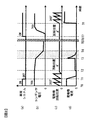
- FIG. 2A shows the ON / OFF state of the ignition switch of the vehicle system
- FIG. 2B shows the voltage of the capacitor 41
- FIG. 2C shows the rotational position of the electric motor 5
- FIG. The current of the electric motor 5 is illustrated with the passage of time on the horizontal axis.
- the period from time T0 to T1 indicates a state where the electric motor 5 is driven. That is, the ignition switch of the vehicle system is in an ON state as shown in FIG. 2A, and the power of the high voltage battery 1 is supplied to the power conversion unit 4 via the relays 2 and 3.
- the power conversion unit 4 converts the power of the high voltage battery 1 from direct current to alternating current and supplies it to the electric motor 5. Therefore, the electric motor 5 is rotationally driven as shown in FIG. In this state, the voltage of the capacitor 41 is a voltage Vdc equivalent to the voltage of the high voltage battery 1 as shown in FIG. Further, as shown in FIG. 2 (d), a current having a predetermined magnitude flows through the electric motor 5. It is assumed that the ON / OFF signal of the ignition switch is transmitted to the control device 43 from a host ECU (not shown).
- the control device 43 opens the relays 2 and 3 at time T2, The voltage battery 1 and the capacitor 41 are electrically disconnected.
- the rotational speed of the electric motor 5 gradually decreases.
- the induced voltage of the electric motor 5 is measured by the voltage detector 45, and when the electric voltage decreases to a predetermined value or less, it is determined that the electric motor 5 has stopped. (The rotation speed of the electric motor 5 is proportional to the induced voltage) Even if the relays 2 and 3 are opened, the electric charge (electric power) remains in the capacitor 41. Therefore, as shown in FIG. The voltage is maintained.
- the estimation of the rotational position of the electric motor 5 is performed with the remaining power of the capacitor 41. That is, the control device 43 creates an energization pattern for determining the rotational position A ° of the electric motor 5 and rotates the electric motor 5 based on the current response of the electric motor 5 when the electric motor 5 is energized according to the created energization pattern. Estimate the position. Specifically, a constant voltage is applied to each phase of the stopped motor 5, the inductance distribution of the motor 5 is measured based on the current value detected by the current detector 44 at this time, and the motor is calculated from the inductance distribution. 5 rotational position A ° is determined.
- the inductance distribution does not include information on the magnetic pole direction
- a fixed voltage for determining the magnetic pole direction is applied using the determined rotational position A °, and the magnetic pole direction is determined based on the current response. .
- Information on the rotational position A ° determined in this way is held in a storage device in the control device 43.
- the rotational position estimation result using the inductance distribution does not include determination of the magnetic pole direction (N pole or S pole). If the electric motor 5 is driven in a state in which the magnetic pole direction is uncertain, there is a possibility of driving in an unintended rotation direction, so it is necessary to estimate the magnetic pole direction.
- a magnetic pole direction estimation means there is a method in which an estimation magnetic flux change is applied to each magnetic pole direction, and the N pole and the S pole are determined from the drive current difference at that time.
- the remaining power of the capacitor 41 is forcibly discharged at time T3. That is, the inverter circuit 42 is energized so that a large current flows through the motor 5, and discharge control is performed up to the low voltage region. As a result, at time T4, as shown in FIG. 2 (b), the voltage of the capacitor 41 is rapidly discharged, and as shown in FIG. 2 (d), the current of the electric motor 5 becomes zero. Note that the discharge rate of the capacitor 41 at this time is higher than the discharge rate of the capacitor 41 when the control device 43 estimates the rotational position of the electric motor 5 during the period from time T2 to time T3.
- Times T5 to T6 indicate the motor system stop period. Even during this stop period, the information on the rotational position A ° stored in the storage device in the control device 43 is retained.
- the control device 43 closes the relays 2 and 3. Then, as shown in FIG. 2B, the voltage of the capacitor 41 is charged.
- the control device 43 starts driving the electric motor 5 as shown in FIG. 2C by driving the inverter circuit 42 at time T8.
- the information on the rotational position A ° is read from the storage device in the control device 43, so that the electric motor 5 can be driven quickly with high torque.
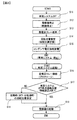
- FIG. 3 is a flowchart for explaining the operation of the motor control device.
- step S13 When the motor 5 is stopped, the relays 2 and 3 are shut off (opened) in step S13, and then the rotational position is estimated in step S14. Information on the rotational position A ° determined by the estimation is held in a storage device in the control device 43. After estimating the rotational position, in step S15, the residual voltage of the capacitor 41 is forcibly discharged, and the electric motor system is safely stopped.
- step S16 a process of reading the rotational position A ° from the storage device is performed in step S17.
- the control device 43 creates an energization pattern for estimating the rotational position of the electric motor 5, and energizes the electric motor 5 according to the created energization pattern to estimate the rotational position.
- step S17 or step S18 the driving of the electric motor 5 is immediately started with high torque based on the rotational position information.
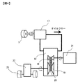
- FIG. 4 is a configuration diagram in which the motor control device of the present embodiment is applied to a hydraulic control system for a vehicle transmission.
- the electric motor 5 is the same as the electric motor 5 shown in FIG. 1, and other configurations for driving the electric motor 5 are the same as those in FIG.
- the oil pump 17 is connected to the electric motor 5.
- the oil pump 17 circulates oil into the transmission 18.
- a pulley 19 and a belt 20 are connected in the transmission 18, and the power of the internal combustion engine 21 is transmitted to the final speed reducer 22 through the pulley 19 and the belt 20 to drive the tire 23.
- the internal combustion engine 21 is stopped in order to quickly cut off the driving force, and the oil pump 17 is stopped so that the driving force is not transmitted to the final reduction gear 22.
- the relays 2 and 3 shown in FIG. 1 are disconnected, the residual voltage in the capacitor 41 is discharged, and the rotational position of the electric motor 5 is estimated.
- the electric motor 5 is energized so that no torque is generated in the electric motor 5 in order to prevent the oil pump 17 from moving.
- the control device 43 shown in FIG. 1 starts driving the electric motor 5 using information on the rotational position stored when the vehicle system is stopped. As a result, the oil pressure in the transmission 18 can be quickly secured, and the driving force of the internal combustion engine 21 can be transmitted to the tire 23 via the final speed reducer 22 without being delayed by the driver's request.
- the motor control device converts the DC power supplied from the high voltage battery 1 into AC power and supplies it to the motor 5, and a capacitor for smoothing the DC power from the high voltage battery 1. 41, and the capacitor 41 is electrically disconnected from the high-voltage battery 1, and the rotational position of the motor 5 is determined based on the current value that flows to the motor 5 by the remaining power of the capacitor 41 when the motor 5 is in a stopped state. And a control device 43 for estimation. Thereby, the electric motor 5 can be rapidly driven with high torque at the time of starting of the electric motor system.
- the control device 43 starts driving the electric motor 5 based on the estimated rotational position. Thereby, the drive of the electric motor 5 can be started quickly with high torque.
- the control device 43 After estimating the rotational position of the electric motor 5, the control device 43 performs discharge control for discharging the remaining power of the capacitor 41 in the power converter 4. Thereby, the remaining electric power of the capacitor 41 after the rotational position is determined can be discharged quickly.
- the discharge speed of the capacitor 41 in the above discharge control is larger than the discharge speed of the capacitor 41 when the control device 43 estimates the rotational position of the electric motor 5.
- the capacitor 41 can be discharged quickly, while a sufficient estimation period of the rotational position of the electric motor 5 can be ensured and accurate rotational position estimation can be performed.
- the current flowing through the electric motor 5 is detected based on the remaining power of the capacitor 41, and the rotational position of the electric motor 5 is estimated based on the current value.
- a direct current flowing through the inverter circuit 42 may be detected. Even in this case, the same control as in the above embodiment can be performed.
- the present invention is not limited to the above-described embodiment, and other forms conceivable within the scope of the technical idea of the present invention are also included in the scope of the present invention as long as the characteristics of the present invention are not impaired. .
Landscapes
- Engineering & Computer Science (AREA)
- Power Engineering (AREA)
- Electric Propulsion And Braking For Vehicles (AREA)
- Stopping Of Electric Motors (AREA)
- Control Of Motors That Do Not Use Commutators (AREA)
Abstract
電動機の起動時に回転位置を推定する制御が必要であり、速やかに高トルクで電動機を起動することができない。 電動機5の回転が停止すると、制御装置43は、時刻T2において、リレー2、3を開成する。リレー2、3を開成しても、図2(b)に示すように、コンデンサ41には電荷(電力)が残っている。このコンデンサ41の残存電力で電動機5の回転位置の推定を実施する。推定された回転位置A°の情報は、制御装置43内の記憶装置に保持される。その後、車両は停止される。そして、次に車両を起動して、コンデンサ41への充電が完了する時刻T8で、制御装置43は、インバータ回路42を駆動して、図2(c)に示すように、電動機5の駆動を開始する。電動機5の駆動を開始する際は、制御装置43内の記憶装置から回転位置A°の情報を読出すことで、速やかに高トルクで電動機5を駆動することができる。
Description
本発明は、電動機制御装置に関する。
電動機の制御において、電動機の回転位置を検出するセンサを使用しないセンサレス制御が行われている。このセンサレス制御では、電動機システムの起動時に基準となる回転位置を推定する制御が必要である。そして、電動機システムの起動時に電動機が脱調しないようにゆっくりと駆動し、回転位置の推定が可能な回転数になってから通常の駆動力で電動機を駆動する。そのため、回転位置センサを用いた制御に比べて、電動機の駆動力の立ち上がり時間が遅くなる。
そこで、センサレス制御において、電動機が停止する時に、電動機の回転位置を次回のシステム起動時に適した回転位置に固定する制御方法が提案されている。この制御方法では、電動機の停止時におけるコンデンサの残電荷によっては電動機の回転位置を起動時に適した回転位置まで制御できない可能性があり、その場合は次回のシステム起動時に回転位置を推定する制御が必要である(特許文献1)。
また、センサレス制御において、バッテリの電力が低下した場合は、電動機を速やかに停止させて電動機の回転位置を記憶しておき、バッテリの電力が復帰した後に、記憶していた回転位置に基づいて電動機の駆動を開始する制御方法が提案されている。この制御方法は、駆動途中の電動機の制御失陥時の対策であり、通常のシステム起動時の制御は考慮されていない(特許文献2)。
一般的に、電動機のセンサレス制御においては、電動機システムの起動時に回転位置を推定する制御が必要であり、速やかに高トルクで電動機を駆動することができない。
本発明による電動機制御装置は、バッテリから供給される直流電力を交流電力に変換して電動機に供給するインバータ回路と、直流電力を平滑化するためのコンデンサと、コンデンサがバッテリと電気的に遮断された状態で、電動機が停止状態であるときにコンデンサの残存電力により電動機またはインバータ回路に流れる電流値に基づいて、電動機の回転位置を推定する制御部とを備える。
本発明によれば、電動機のセンサレス制御において、電動機システムの起動時に速やかに高トルクで電動機を駆動することができる。
以下、本発明による電動機制御装置の実施形態について図面に基づいて説明する。図1は、車両用の電動機システムに搭載された電動機制御装置の全体システム構成を示す図である。図1に示すように、高電圧バッテリ1の電力は、リレー2、3を介して電力変換部4に供給される。電力変換部4は、高電圧バッテリ1の電力を直流から交流に変換して電動機5に供給する。電力変換部4は、コンデンサ41、インバータ回路42、制御装置43、電流検出器44、電圧検出器45を有している。制御装置43は、インバータ回路42へ駆動信号を出力する。インバータ回路42は、制御装置43からの駆動信号により駆動され、高電圧バッテリ1からの直流電力を交流電力に変換する。コンデンサ41は、高電圧バッテリ1からインバータ回路42に供給される直流電圧を平滑化するためのものである。リレー2、3は、制御装置43の制御により、開成もしくは閉成される。
電流検出器44は、電動機5に流れる電流を検出し、検出した電流値を制御装置43へ出力する。電圧検出器45は、コンデンサ41の電圧を検出し、検出した電圧値を制御装置43へ出力する。
次に、図2のタイムチャートを参照して本実施形態における電動機制御装置の動作を説明する。
図2(a)は、車両システムのイグニッションスイッチのON/OFF状態、図2(b)は、コンデンサ41の電圧、図2(c)は、電動機5の回転位置、図2(d)は、電動機5の電流であり、それぞれ横軸の時間経過と共に図示したものである。
図2(a)は、車両システムのイグニッションスイッチのON/OFF状態、図2(b)は、コンデンサ41の電圧、図2(c)は、電動機5の回転位置、図2(d)は、電動機5の電流であり、それぞれ横軸の時間経過と共に図示したものである。
時刻T0~T1の期間は、電動機5が駆動されている状態を示す。すなわち、車両システムのイグニッションスイッチは、図2(a)に示すようにON状態であり、高電圧バッテリ1の電力が、リレー2、3を介して電力変換部4に供給されている。そして、電力変換部4は、高電圧バッテリ1の電力を直流から交流に変換して電動機5に供給している。したがって、電動機5は、図2(c)に示すように回転駆動されている。この状態では、コンデンサ41の電圧は、図2(b)に示すように、高電圧バッテリ1の電圧と同等の電圧Vdcである。また、電動機5には、図2(d)に示すように、所定の大きさの電流が流れている。なお、イグニッションスイッチのON/OFF信号は図示省略した上位のECUから制御装置43へ伝達されるものとする。
時刻T1で、車両システムのイグニッションスイッチがOFFされたとする。この時、制御装置43は、インバータ回路42の駆動を停止する。そのため、図2(c)に示すように、電動機5の回転が徐々に減衰して停止する。そして、図2(d)に示すように、電動機5の電流はゼロに減少していく。
制御装置43は、電動機5の回転が停止すると(“電動機5の回転の停止”をどのようにして検出するのか不明)、制御装置43は、時刻T2において、リレー2、3を開成し、高電圧バッテリ1とコンデンサ41を電気的に遮断する。なお、電力変換部4の動作を停止すると電動機5の回転数は徐々に低くなる。この時電圧検出器45にて電動機5の誘起電圧を測定し、所定値以下まで低下した場合、電動機5は停止したと判定する。(電動機5の回転数は誘起電圧に比例する)リレー2、3を開成しても、コンデンサ41には電荷(電力)が残っているため、図2(b)に示すように、コンデンサ41の電圧が維持される。このコンデンサ41の残存電力で電動機5の回転位置の推定を実施する。すなわち、制御装置43は、電動機5の回転位置A°を決定するための通電パターンを作成し、作成した通電パターンに従って電動機5を通電した時の電動機5の電流応答に基づいて、電動機5の回転位置を推定する。具体的には、停止している電動機5の各相毎に一定電圧を通電し、この時に電流検出器44で検出された電流値に基づいて電動機5のインダクタンス分布を測定し、インダクタンス分布から電動機5の回転位置A°を決定する。なお、インダクタンス分布には磁極方向の情報が含まれていないが、決定した回転位置A°を用いて磁極方向を判定するための一定電圧を印加し、その電流応答に基づいて磁極方向を決定する。このようにして決定された回転位置A°の情報は、制御装置43内の記憶装置に保持される。なお、インダクタンス分布を利用した回転位置推定結果は、磁極方向(N極またはS極)の判定が含まれていない。磁極方向未確定の状態で電動機5を駆動すると、意図しない回転方向に駆動する可能性があるため、磁極方向を推定する必要がある。磁極方向の推定手段としては、それぞれの磁極方向に推定用の磁束変化を加え、その時の駆動電流差分からN極とS極を判定する方法がある。
回転位置の決定が完了した後、時刻T3において、コンデンサ41の残存電力を強制放電する。すなわち、電動機5に大電流が流れるようにインバータ回路42を通電状態にし、低電圧領域まで放電制御を実施する。この結果、時刻T4において、図2(b)に示すように、コンデンサ41の電圧は急激に放電され、図2(d)に示すように、電動機5の電流はゼロとなる。なお、この時のコンデンサ41の放電速度は、時刻T2から時刻T3までの期間に制御装置43が電動機5の回転位置を推定する時のコンデンサ41の放電速度よりも大きい。
時刻T5~T6は電動機システムの停止期間を示す。なお、この停止期間においても制御装置43内の記憶装置に記憶された回転位置A°の情報は保持されている。
時刻T7において、イグニッションスイッチがONにされると、電動機システムを起動する。すると、制御装置43は、リレー2、3を閉成する。そして、図2(b)に示すように、コンデンサ41の電圧が充電される。コンデンサ41への充電が完了すると、時刻T8で、制御装置43は、インバータ回路42を駆動することにより、図2(c)に示すように、電動機5の駆動を開始する。電動機5の駆動を開始する際は、制御装置43内の記憶装置から回転位置A°の情報を読出すことで、速やかに高トルクで電動機5を駆動することができる。
図3は電動機制御装置の動作を説明するフローチャートである。車両システムの動作状態において、ステップS11で、イグニッションスイッチがOFFされると、ステップS12で、制御装置43は、インバータ回路42の駆動を停止する。したがって、電動機5の回転が徐々に減衰して停止する。
電動機5が停止されると、ステップS13でリレー2、3を遮断(開放)した後、ステップS14で、回転位置の推定を実施する。推定により決定した回転位置A°の情報は、制御装置43内の記憶装置に保持される。回転位置を推定後、ステップS15で、コンデンサ41の残電圧は強制放電が実施され、電動機システムを安全に停止状態にする。
そして、次に電動機システムを起動した場合は、ステップS16で、リレー2、3を閉成してコンデンサ41が充電される。充電が完了すると、ステップS17で、記憶装置から回転位置A°を読み込む処理を行う。一方、記憶装置に回転位置A°が記憶されていない場合は、読込みNGと判定され、ステップS18に進み、電動機5の回転位置の推定を行う。すなわち、起動時に、前述したと同様に、制御装置43は、電動機5の回転位置を推定するための通電パターンを作成し、作成した通電パターンに従って電動機5を通電して回転位置を推定する。
ステップS17もしくはステップS18で回転位置が決定されると、次のステップS19で、回転位置の情報に基づいて、速やかに高トルクで電動機5の駆動を開始する。
図4は本実施形態の電動機制御装置を車両用変速機の油圧制御システムに適用した構成図である。電動機5は、図1に示す電動機5と同一であり、電動機5を駆動するその他の構成は図示を省略したが図1と同様である。
オイルポンプ17は、電動機5に連結されている。オイルポンプ17は、変速機18内へオイルを循環する。変速機18内にはプーリ19とベルト20が連結され、内燃機関21の動力を、プーリ19、及びベルト20を介して最終減速機22に伝達し、タイヤ23を駆動する。
車両システムの停止時には、速やかに駆動力を遮断させるため、内燃機関21を停止し、最終減速機22に駆動力が伝達しないようにオイルポンプ17を停止する。オイルポンプ17の停止後は、図1に示すリレー2、3を遮断し、コンデンサ41内の残電圧を放電すると共に、電動機5の回転位置の推定を実施する。この時、オイルポンプ17が動かないようにするため電動機5にトルクが発生しないように電動機5への通電を実施する。
車両システムの起動時は、変速機18内のプーリ19とベルト20が滑らないようにするため、オイルポンプ17を所定の回転数まで駆動し、予めオイル圧力を確保する必要がある。速やかにオイルポンプ17を所定の回転数まで上げるためには、電動機5を速やかに高トルクで駆動する必要がある。図1に示す制御装置43は、車両システムの停止時に記憶していた回転位置の情報を用いて電動機5の駆動を開始する。これにより、変速機18内のオイル圧力を速やかに確保することができ、ドライバーの要求に遅れること無く、内燃機関21の駆動力を最終減速機22を介してタイヤ23に伝達することができる。
以上説明した実施形態によれば、次の作用効果が得られる。
(1)電動機制御装置は、高電圧バッテリ1から供給される直流電力を交流電力に変換して電動機5に供給するインバータ回路42と、高電圧バッテリ1からの直流電力を平滑化するためのコンデンサ41と、コンデンサ41が高電圧バッテリ1と電気的に遮断された状態で、電動機5が停止状態である時にコンデンサ41の残存電力により電動機5に流れる電流値に基づいて、電動機5の回転位置を推定する制御装置43とを備える。これにより、電動機システムの起動時に速やかに高トルクで電動機5を駆動することができる。
(1)電動機制御装置は、高電圧バッテリ1から供給される直流電力を交流電力に変換して電動機5に供給するインバータ回路42と、高電圧バッテリ1からの直流電力を平滑化するためのコンデンサ41と、コンデンサ41が高電圧バッテリ1と電気的に遮断された状態で、電動機5が停止状態である時にコンデンサ41の残存電力により電動機5に流れる電流値に基づいて、電動機5の回転位置を推定する制御装置43とを備える。これにより、電動機システムの起動時に速やかに高トルクで電動機5を駆動することができる。
(2)制御装置43は、推定された回転位置に基づいて電動機5の駆動を開始する。これにより、速やかに高トルクで電動機5の駆動を開始することができる。
(3)制御装置43は、電動機5の回転位置を推定した後、電力変換部4内のコンデンサ41の残存電力を放電する放電制御を行う。これにより、回転位置が決定された後のコンデンサ41の残存電力を速やかに放電することができる。
(4)上記の放電制御におけるコンデンサ41の放電速度は、制御装置43が電動機5の回転位置を推定するときのコンデンサ41の放電速度よりも大きい。これにより、放電制御ではコンデンサ41を素早く放電させる一方で、電動機5の回転位置の推定期間を十分に確保し、正確な回転位置推定を行うことができる。
なお、上記実施形態では、電動機5が停止状態である時にコンデンサ41の残存電力により電動機5に流れる電流を検出し、その電流値に基づいて電動機5の回転位置を推定することとしたが、電動機5の電流を検出する代わりに、インバータ回路42に流れる直流電流を検出しても良い。このようにしても、上記実施形態と同様の制御を行うことができる。
本発明は、上記の実施形態に限定されるものではなく、本発明の特徴を損なわない限り、本発明の技術思想の範囲内で考えられるその他の形態についても、本発明の範囲内に含まれる。
1 高電圧バッテリ
2、3 リレー
4 電力変換部
41 コンデンサ
42 インバータ回路
43 制御装置
44 電流検出器
45 電圧検出器
17 オイルポンプ
18 変速機
19 プーリ
20 ベルト
21 内燃機関
22 最終減速機
23 タイヤ
2、3 リレー
4 電力変換部
41 コンデンサ
42 インバータ回路
43 制御装置
44 電流検出器
45 電圧検出器
17 オイルポンプ
18 変速機
19 プーリ
20 ベルト
21 内燃機関
22 最終減速機
23 タイヤ
Claims (4)
- バッテリから供給される直流電力を交流電力に変換して電動機に供給するインバータ回路と、
前記直流電力を平滑化するためのコンデンサと、
前記コンデンサが前記バッテリと電気的に遮断された状態で、前記電動機が停止状態であるときに前記コンデンサの残存電力により前記電動機または前記インバータ回路に流れる電流値に基づいて、前記電動機の回転位置を推定する制御部とを備える電動機制御装置。 - 請求項1に記載の電動機制御装置において、
前記制御部は、前記推定された前記回転位置に基づいて前記電動機の駆動を開始する電動機制御装置。 - 請求項1または2に記載の電動機制御装置において、
前記制御部は、前記電動機の回転位置を推定した後、前記コンデンサの残存電力を放電する放電制御を行う電動機制御装置。 - 請求項3に記載の電動機制御装置において、
前記放電制御における前記コンデンサの放電速度は、前記制御部が前記電動機の回転位置を推定するときの前記コンデンサの放電速度よりも大きい電動機制御装置。
Priority Applications (1)
| Application Number | Priority Date | Filing Date | Title |
|---|---|---|---|
| JP2017529543A JPWO2017014063A1 (ja) | 2015-07-23 | 2016-07-08 | 電動機制御装置 |
Applications Claiming Priority (2)
| Application Number | Priority Date | Filing Date | Title |
|---|---|---|---|
| JP2015-145403 | 2015-07-23 | ||
| JP2015145403 | 2015-07-23 |
Publications (1)
| Publication Number | Publication Date |
|---|---|
| WO2017014063A1 true WO2017014063A1 (ja) | 2017-01-26 |
Family
ID=57834024
Family Applications (1)
| Application Number | Title | Priority Date | Filing Date |
|---|---|---|---|
| PCT/JP2016/070203 Ceased WO2017014063A1 (ja) | 2015-07-23 | 2016-07-08 | 電動機制御装置 |
Country Status (2)
| Country | Link |
|---|---|
| JP (1) | JPWO2017014063A1 (ja) |
| WO (1) | WO2017014063A1 (ja) |
Citations (2)
| Publication number | Priority date | Publication date | Assignee | Title |
|---|---|---|---|---|
| JP2001136779A (ja) * | 1999-11-05 | 2001-05-18 | Mitsubishi Heavy Ind Ltd | ブラシレスdcモータの初期位置検出方法及び初期位置検出装置を有したブラシレスdcモータ |
| JP2014100043A (ja) * | 2012-10-19 | 2014-05-29 | Mitsubishi Heavy Ind Ltd | モータ駆動装置及びその放電制御方法 |
-
2016
- 2016-07-08 WO PCT/JP2016/070203 patent/WO2017014063A1/ja not_active Ceased
- 2016-07-08 JP JP2017529543A patent/JPWO2017014063A1/ja active Pending
Patent Citations (2)
| Publication number | Priority date | Publication date | Assignee | Title |
|---|---|---|---|---|
| JP2001136779A (ja) * | 1999-11-05 | 2001-05-18 | Mitsubishi Heavy Ind Ltd | ブラシレスdcモータの初期位置検出方法及び初期位置検出装置を有したブラシレスdcモータ |
| JP2014100043A (ja) * | 2012-10-19 | 2014-05-29 | Mitsubishi Heavy Ind Ltd | モータ駆動装置及びその放電制御方法 |
Also Published As
| Publication number | Publication date |
|---|---|
| JPWO2017014063A1 (ja) | 2018-03-01 |
Similar Documents
| Publication | Publication Date | Title |
|---|---|---|
| RU2613185C2 (ru) | Основанный на электрическом токе алгоритм блокировки автоматической остановки двигателя и система, его осуществляющая | |
| RU2576642C2 (ru) | Способ автоматической остановки и автоматического запуска двигателя | |
| JP5840718B2 (ja) | ブラシレスモータの制御装置及び始動方法 | |
| US20150019079A1 (en) | Method of inhibiting an automatic engine stop during steering maneuver | |
| JP6030466B2 (ja) | ブラシレスモータの駆動装置 | |
| EP3109995B1 (en) | Actuator control device and control method | |
| US9979331B2 (en) | Method for controlling a motor | |
| US8890451B2 (en) | Sensorless control unit for brushless DC motor | |
| JPWO2015041321A1 (ja) | 3相ブラシレスモータの駆動装置 | |
| WO2014061691A1 (ja) | モータ駆動装置及びその放電制御方法 | |
| CN113386733A (zh) | 混合动力车辆的驱动系统 | |
| KR102581825B1 (ko) | 자동차 내에서 액추에이터의 위치를 결정하기 위한 센서 어레인지먼트 및 센서 어레인지먼트를 작동시키기 위한 방법 | |
| CN115347837B (zh) | 电机控制方法、控制器、计算机存储设备及气悬浮系统 | |
| CN109478862B (zh) | 旋转电机的控制装置及控制方法 | |
| JP6585651B2 (ja) | モータ制御装置及びステッピングモータの制御方法 | |
| JPWO2017014063A1 (ja) | 電動機制御装置 | |
| JP6036494B2 (ja) | 燃料ポンプの制御装置 | |
| JP6729328B2 (ja) | モータ制御装置 | |
| JP2012228017A (ja) | 発電電動機の制御装置 | |
| JP5144322B2 (ja) | 電動機制御装置 | |
| JP3787924B2 (ja) | 電気自動車の駆動制御装置 | |
| JP6357648B2 (ja) | 直流電動機駆動装置とそれを搭載した天井埋込型換気装置 | |
| CN103684122A (zh) | 开关磁阻电机的控制方法及装置 | |
| JP2007181330A (ja) | モータ制御装置および制御方法 | |
| JP2008199747A (ja) | 誘導機システム制御装置及び誘導機システム異常判定方法 |
Legal Events
| Date | Code | Title | Description |
|---|---|---|---|
| 121 | Ep: the epo has been informed by wipo that ep was designated in this application |
Ref document number: 16827625 Country of ref document: EP Kind code of ref document: A1 |
|
| ENP | Entry into the national phase |
Ref document number: 2017529543 Country of ref document: JP Kind code of ref document: A |
|
| NENP | Non-entry into the national phase |
Ref country code: DE |
|
| 122 | Ep: pct application non-entry in european phase |
Ref document number: 16827625 Country of ref document: EP Kind code of ref document: A1 |