WO2017011320A1 - Rapidly dissolvable microneedles for the transdermal delivery of therapeutics - Google Patents
Rapidly dissolvable microneedles for the transdermal delivery of therapeutics Download PDFInfo
- Publication number
- WO2017011320A1 WO2017011320A1 PCT/US2016/041571 US2016041571W WO2017011320A1 WO 2017011320 A1 WO2017011320 A1 WO 2017011320A1 US 2016041571 W US2016041571 W US 2016041571W WO 2017011320 A1 WO2017011320 A1 WO 2017011320A1
- Authority
- WO
- WIPO (PCT)
- Prior art keywords
- microneedle
- pvp
- microneedles
- skin
- flexible
- Prior art date
Links
Classifications
-
- A—HUMAN NECESSITIES
- A61—MEDICAL OR VETERINARY SCIENCE; HYGIENE
- A61L—METHODS OR APPARATUS FOR STERILISING MATERIALS OR OBJECTS IN GENERAL; DISINFECTION, STERILISATION OR DEODORISATION OF AIR; CHEMICAL ASPECTS OF BANDAGES, DRESSINGS, ABSORBENT PADS OR SURGICAL ARTICLES; MATERIALS FOR BANDAGES, DRESSINGS, ABSORBENT PADS OR SURGICAL ARTICLES
- A61L31/00—Materials for other surgical articles, e.g. stents, stent-grafts, shunts, surgical drapes, guide wires, materials for adhesion prevention, occluding devices, surgical gloves, tissue fixation devices
- A61L31/14—Materials characterised by their function or physical properties, e.g. injectable or lubricating compositions, shape-memory materials, surface modified materials
- A61L31/16—Biologically active materials, e.g. therapeutic substances
-
- A—HUMAN NECESSITIES
- A61—MEDICAL OR VETERINARY SCIENCE; HYGIENE
- A61K—PREPARATIONS FOR MEDICAL, DENTAL OR TOILETRY PURPOSES
- A61K47/00—Medicinal preparations characterised by the non-active ingredients used, e.g. carriers or inert additives; Targeting or modifying agents chemically bound to the active ingredient
- A61K47/30—Macromolecular organic or inorganic compounds, e.g. inorganic polyphosphates
- A61K47/32—Macromolecular compounds obtained by reactions only involving carbon-to-carbon unsaturated bonds, e.g. carbomers, poly(meth)acrylates, or polyvinyl pyrrolidone
-
- A—HUMAN NECESSITIES
- A61—MEDICAL OR VETERINARY SCIENCE; HYGIENE
- A61K—PREPARATIONS FOR MEDICAL, DENTAL OR TOILETRY PURPOSES
- A61K9/00—Medicinal preparations characterised by special physical form
- A61K9/0012—Galenical forms characterised by the site of application
- A61K9/0019—Injectable compositions; Intramuscular, intravenous, arterial, subcutaneous administration; Compositions to be administered through the skin in an invasive manner
- A61K9/0021—Intradermal administration, e.g. through microneedle arrays, needleless injectors
-
- A—HUMAN NECESSITIES
- A61—MEDICAL OR VETERINARY SCIENCE; HYGIENE
- A61L—METHODS OR APPARATUS FOR STERILISING MATERIALS OR OBJECTS IN GENERAL; DISINFECTION, STERILISATION OR DEODORISATION OF AIR; CHEMICAL ASPECTS OF BANDAGES, DRESSINGS, ABSORBENT PADS OR SURGICAL ARTICLES; MATERIALS FOR BANDAGES, DRESSINGS, ABSORBENT PADS OR SURGICAL ARTICLES
- A61L31/00—Materials for other surgical articles, e.g. stents, stent-grafts, shunts, surgical drapes, guide wires, materials for adhesion prevention, occluding devices, surgical gloves, tissue fixation devices
- A61L31/04—Macromolecular materials
- A61L31/048—Macromolecular materials obtained by reactions only involving carbon-to-carbon unsaturated bonds
-
- A—HUMAN NECESSITIES
- A61—MEDICAL OR VETERINARY SCIENCE; HYGIENE
- A61L—METHODS OR APPARATUS FOR STERILISING MATERIALS OR OBJECTS IN GENERAL; DISINFECTION, STERILISATION OR DEODORISATION OF AIR; CHEMICAL ASPECTS OF BANDAGES, DRESSINGS, ABSORBENT PADS OR SURGICAL ARTICLES; MATERIALS FOR BANDAGES, DRESSINGS, ABSORBENT PADS OR SURGICAL ARTICLES
- A61L2300/00—Biologically active materials used in bandages, wound dressings, absorbent pads or medical devices
- A61L2300/40—Biologically active materials used in bandages, wound dressings, absorbent pads or medical devices characterised by a specific therapeutic activity or mode of action
- A61L2300/416—Anti-neoplastic or anti-proliferative or anti-restenosis or anti-angiogenic agents, e.g. paclitaxel, sirolimus
-
- A—HUMAN NECESSITIES
- A61—MEDICAL OR VETERINARY SCIENCE; HYGIENE
- A61L—METHODS OR APPARATUS FOR STERILISING MATERIALS OR OBJECTS IN GENERAL; DISINFECTION, STERILISATION OR DEODORISATION OF AIR; CHEMICAL ASPECTS OF BANDAGES, DRESSINGS, ABSORBENT PADS OR SURGICAL ARTICLES; MATERIALS FOR BANDAGES, DRESSINGS, ABSORBENT PADS OR SURGICAL ARTICLES
- A61L2400/00—Materials characterised by their function or physical properties
- A61L2400/12—Nanosized materials, e.g. nanofibres, nanoparticles, nanowires, nanotubes; Nanostructured surfaces
-
- A—HUMAN NECESSITIES
- A61—MEDICAL OR VETERINARY SCIENCE; HYGIENE
- A61M—DEVICES FOR INTRODUCING MEDIA INTO, OR ONTO, THE BODY; DEVICES FOR TRANSDUCING BODY MEDIA OR FOR TAKING MEDIA FROM THE BODY; DEVICES FOR PRODUCING OR ENDING SLEEP OR STUPOR
- A61M37/00—Other apparatus for introducing media into the body; Percutany, i.e. introducing medicines into the body by diffusion through the skin
- A61M37/0015—Other apparatus for introducing media into the body; Percutany, i.e. introducing medicines into the body by diffusion through the skin by using microneedles
- A61M2037/0053—Methods for producing microneedles
Definitions
- microneedle devices have become an attractive method to overcome the diffusion-limiting epidermis and effectively transport therapeutics to the body.
- Microneedles are arrays of micron-sized projections that pierce the skin to administer drugs, manually creating channels for the passage of a therapeutic.
- Biodegradable or water-soluble microneedles are of high interest due to their safety, low device complexity, and ability to deliver agents of nearly any size.
- the main limitation of biodegradable microneedles is their arduous manufacturing, requiring long vacuum and centrifugation steps to fill a mold.
- Figure 1 FDA New Molecular Entities (NME) approved from 2006-2010.
- Figure 2 The anatomy of the skin. 2
- FIG. 29 Transdermal drug delivery via microneedle devices. 29
- Figure 4 Schematics of the application strategies for the four main
- Figure 6 Polymer microneedle array manufactured by the Prausnitz group.
- Figure 7 Scheme depicting the PRINT process; (1) delivery sheet casting; (2) particle fabrication; (3) particle collection; (4) particle harvesting. 4
- FIG. 8 Schematics of the applications of traditional biodegradable microneedles made using PRINT.
- the backing is then removed.
- the needles (red) and substrate (yellow) are inserted into the skin.
- the backing is then dissolved with tap water.
- Figure 9 ESEM images of SU-8 Master template (A & B), PDMS template (C & D) and PFPE mold (E & F) and PVP microneedles (G & H) made from R2 SU-8 master (200 ⁇ squares, 200 ⁇ spacing). Needles show comparable lengths and tip radii. Scale bars on A, C, E, and G are 500 ⁇ . Scale bars for B, D, F, and H are 200 ⁇ .
- FIG 11 Inclined, rotated photolithography schematic for making microneedle master templates.
- An SU-8 coated wafer is placed on a tilted stage (18-25°) and exposed. The substrate was then rotated 90° about the surface normal and exposed once more. After a total of four exposures, the wafer is post-exposure baked (PEB) and developed, leaving a negative master template.
- PEB post-exposure baked
- Figure 12 DSC traces for harvesting layers investigated for the flexible, water- soluble harvesting layers.
- A VA64
- B VA64+2% triethyl citrate
- C VA64+2% triethyl citrate+0.5% fluorescein dye.
- Figure 13 Schematic of the PRINT process for making microneedles, including the fabrication of individual microneedles and harvesting onto the flexible, water- soluble substrate.
- a film of PVP red
- a perfluoropolyether mold green
- the filled mold is then separated from the film.
- B The filled mold is mated to a flexible, water- soluble substrate (yellow) for harvesting and passed through a heated nip at 65 °C. After separation, a microneedle array on the substrate remains.
- Figure 14 Array of PRINTed PVP microneedles harvested on engineered flexible substrate.
- Figure 15 Fluorescent drug surrogates incorporated into PRINT microneedles.
- Rhodamine B base shown with a chloride counter ion.
- DyLight 680 shown with a maleimide functional handle. 24 ' 25
- Figure 16 Confocal microscopic images of films and microneedles incorporating the selected fluorescent drug surrogates, rhodamine B and DyLight 680.
- Rhodamine B film Rhodamine B film
- Rhodamine B microneedle Rhodamine B microneedle
- DyLight 680 film DyLight 680 microneedle.
- Figure 17 Brightfield macroscopic images of a microneedle patch.
- microneedle array morphology showing reproducible needles. Scale bar is 200 ⁇ .
- B A curled microneedle array, showing the flexibility of the array. Scale bar is 1 cm.
- C A side view of a curled microneedle array, showing the size of the array in comparison to human fingers. Scale bar is 1 cm.
- Figure 18 Crystallography structures of the drug surrogate proteins selected for microneedle incorporation.
- Figure 19 Confocal microscopy and ESEM images of pre-microneedle films (top) and microneedles (bottom) containing protein drug surrogates. (Left)
- Figure 21 SEM images of 80 x 320 nm hydrogel PRTNT particles.
- Figure 22 Films and microneedles with bare (+) 80 x 320 nm particles incorporated via a variety of solvents at a loading of 10 wt%.
- A H 2 0,
- B ACN,
- C EtOH,
- D IP A,
- E MeOH.
- Figure 23 ESEM (left) and confocal microscopy (right) images of PVP microneedles and films loaded with 80 x 320 nm bare hydrogel particles.
- Figure 24 Films (above) and microneedles (below) loaded with 5 wt% 80 x 320 nm hydrogel particles. All particles have been tagged (during PRINTing) with 488 maleimide for ex vivo compatibility.
- A Bare (+) particles
- B PEGylated (neu) particles
- C Acetylated (-) particles.
- Figure 25 3 ⁇ 4 NMR traces for the starting product and final product show a complete disappearance of the alcohol at 3.8 ppm (A) and the appearance of methylene at 4.45 ppm and vinyl proteins around 5-5.6 ppm (B).
- A Z-DOL 4000,
- B 4K PFPE-dMA.
- FIG. 26 OCT images taken after the application of flexible (left) and rigid (right) PVP PRINT microneedle patches. Brackets indicate the different features imaged.
- A Air above the patch,
- B Backing layer
- C Murine skin.
- Figure 27 Brightfield macroscopic image after testing with microneedle patch for 10 s. The pattern of the microneedles can be seen on the skin. In the insert, a single piercing is highlighted. Scale bar is 400 ⁇ .
- Figure 28 Brightfield macroscopic images of a microneedle array before and after insertion into ex vivo mouse skin for 10 s. (A) Microneedle array before testing and, (B) Array after testing and removal. Scale bars are 400 ⁇ .
- Figure 29 Image of murine skin after the application of a rhodamine-loaded
- microneedle patch for 10 min and less than 200 ⁇ _, of water to dissolve away that patch backing. Image was taken immediately after dispensing water onto the patch. The backing used was loaded with 0.1% fluorescein dye for imaging purposes. Scale bar is 1 cm.
- Figure 30 Brightfield macroscopic images of murine skin after fixation.
- A Control murine skin, not exposed to microneedles.
- B Murine skin after the insertion of rhodamine-loaded microneedles for 10 min. After insertion, the flexible backing was dissolved, and the skin was wiped clean before fixing. The dye can be seen throughout the skin after this processing, indicating that the drug surrogate diffused within the skin. Scale bar on all images is 1 cm.
- Figure 31 Brightfield microscopic images of skin sections after sectioning
- Figure 32 Fluorescent microscopy images of skin after sectioning.
- A Control skin
- B Skin after 10 second microneedle application
- C Skin after 10 minute microneedle application.
- Epidermis top.
- Scale bar is 35 ⁇ .
- Figure 33 Static Franz diffusion cell apparatus. 6
- Figure 34 Release profiles of rhodamine through ex vivo murine tissue over 24 h. It was seen that the microneedles delivered a significantly higher dose than the solution at all given times.
- Figure 35 Fluorescent microscopy images, shown as overlays with the brightfield channel, of skin after the application of a rhodamine drug surrogate for 24 hours on a Franz cell apparatus.
- A Control (no rhodamine applied),
- B rhodamine delivered via pre-microneedle solution, and
- C rhodamine delivered via microneedles.
- Epidermis top.
- Scale bar is 40 ⁇ .
- Figure 36 Fluorescent microscopy images, shown as overlays with the brightfield channel, of skin after the application of pre-microneedle films containing protein drug surrogates [(A) aldolase, (B) OVA].
- Epidermis top.
- Scale bar is 40 ⁇ .
- Figure 37 Release profiles of protein drug surrogates, aldolase and OVA, through ex vivo murine tissue over 24 h. It was seen that the smaller protein was able to permeate the skin at a much higher efficiency, up to 18% of the loaded dose.
- Figure 39 Release profiles of bare (+), PEGylated (neu), and acetylated (-) 80 x 320 nm PRINT hydrogel particles through ex vivo murine tissue over 24 h. It was seen that the microneedles showed no significant differences in release profile due to surface charge over this time period.
- Figure 40 Fluorescent microscopy images, shown as overlays with the brightfield channel, of skin after the application of microneedles loaded with 80 x 320 nm PRINT particles for 24 hours on a Franz cell apparatus.
- A control
- B bare particles
- C PEGylated particles
- D acetylated particles. Particles are show to be localized to the site of penetration with all surface charges.
- Figure 41 Nude mouse with a PRINT microneedle patch applied to the back. Patch is loaded with 0.1 wt% Dylight 680 cargo.
- Figure 42 Mice at three points during the time course small molecule dye study: (Top) All patches on, (Middle) two patches wiped, and (bottom) all patches wiped. The clean wipe after final water application is highlighted in the middle image.
- Figure 43 Organ harvest of a mouse after the conclusion (72 min) of the small
- Figure 44 Microscopy images of skin penetration studies performed on ex vivo
- Figure 47 PVP microneedles with encapsulated BuChE made from films cast in water.
- A 5 wt% BuChE,
- B 10 wt% BuChE,
- C 15 wt% BuChE,
- D 20 wt% BuChE,
- E 25 wt% BuChE.
- Scale bars are 200 ⁇ on all.
- Figure 48 Recovered BuChE activity after PRINT processing determined via a
- Figure 49 Confocal images of PVP microneedles and films loaded with fluorescein- tagged BuChE. Representative images of 0.1 wt% (top), 5 wt% (middle), and 25 wt% (bottom) BuChE are shown. With increased BuChE loading, the distribution of protein became increasingly more homogenous.
- Figure 50 Confocal microscopy images of microneedles loaded with 20 wt% BuChE tagged with an AlexaFluor 488 probe.
- Figure 51 Confocal (top) and ESEM (bottom) images of microneedles made with 5 wt% BuChE cast in either CAN (left) or EtOH (right).
- Figure 52 SEM of 1 ⁇ PRTNT particles composed of 90% BuChE.
- Figure 53 Confocal images of PVP films containing BuChE 1 ⁇ particles. (A) Non- crosslinked particles, and (B) Crosslinked BuChE 1 ⁇ particles.
- Figure 54 ESEM and confocal images of PRINT PVP microneedles incorporating 1 ⁇ BuChE PRINT particles, (top) Non-crosslinked, and (bottom) Crosslinked particles.
- Figure 55 SEM images of crosslinked 1 ⁇ BuChE particles after release from (A) PVP films and (B) PVP microneedles.
- Figure 56 Release profiles of BuChE through ex vivo murine tissue over 24 h. (A) BuChE alone, and (B) this enzyme in comparison to OVA and aldolase.
- Figure 57 Fluorescent microscopy images, shown as overlays with the brightfield channel, of skin after the application microneedles loaded with free tetrameric BuChE for 24 hours on a Franz cell apparatus.
- the enzyme is localized below the skin in select regions of the lower epidermis.
- Epidermis top.
- Scale bar is 40 ⁇ .
- Figure 58 Chest wall presentation of one patient with IBC.
- Figure 59 Structure of docetaxel.
- Figure 60 DSC trace of the 20 wt% docetaxel (in PVP) film, showing only a glass transition temperature at 38.91 °C.
- Figure 61 ESEM images of microneedles loaded with 5 wt% docetaxel. Scale bars are 100 ⁇ .
- Figure 62 Nu/Nu mouse from the microneedle MTD study after four weeks of dosing with 20 wt% docetaxel microneedle patch. Patch application location is outlined with a black circle. Skin conditions appear unchanged before and after each dose.
- Figure 63 Key white blood cell and red blood cell levels as determined from the microneedle MTD study on nude non-tumor bearing mice. Total WBC count, as well as lymphocyte, granulocyte, and monocyte individual levels, did not vary predictably with dose. Total red blood cell and platelet counts also did not show dose-dependent changes. All parameters were within the normal ranges for nu/nu mice.
- Figure 64 Nu/Nu tumor-bearing mouse (SUM149 model) with a 20 wt% docetaxel microneedle patch affixed to the skin directly above the tumor mass. Patch application location is outlined with a black circle.
- Figure 65 Chromatograms of a representative standard, film, and microneedle patch are shown. The PVP peak can be seen at 14.3 minutes and the docetaxel peak at 27.0 min all materials analyzed. Chromatograms are displayed as observed in ChemStation (Agilent).
- Figure 66 Drawing lithography for microneedle master fabrication, developed by Lee and Jung. 26
- A The glass transition history of the SU-8 polymer in the cooled- down temperature.
- B After the SU-8 contacted the patterned pillar, drawing lithography was performed.
- C Drawing caused the appearance of an extended conical -shaped bridge between the plate and pillar in the glass transition.
- D The desired liquid bridge was cured to generate a rigid structure.
- E The separation of the 3D microstructure bridge at the narrow necking position by isolation drawing produced the ultrahigh aspect ratio solid microneedle molds.
- Figure 67 Long, medium, and short microneedles to target the dermis, lower epidermis, and stratum corneum respectively.
- Figure 68 Structure of (A) docetaxel, (B) lipidized docetaxel with a C 4 alkyl chain, (C) lipidized docetaxel with a C 8 chain.
- microneedles as compared to the particle wt% charged, 2.5% 52
- Table 7 Glass transition temperatures (T g ) observed via DSC of VA64 substrates loaded with plasticizers and fluorescein dye 55
- Table 8 Microneedle depth of penetration as determined by OCT 69
- Table 13 Change in cholinesterase activity after high activity BuChE microneedle administration in vivo, as determined by the UNC Histology Core 101
- Table 14 Glass transition temperatures (T g ) of the PVP pre-microneedle films loaded with docetaxel 112
- Table 17 Study parameters for the determination of the MTD of patch-administered docetaxel to the skin 116
- Table 18 Average dose delivered with docetaxel per patch loading with a 1 cm 2
- IP A isopropanol IV intravenous
- PVME/MA poly(methylvinylether-co-maleic anhydride)
- ID, 2D, 3D one, two, or three dimensional
- microneedle device application in vivo was optimized on nude murine models, and it was shown that these devices efficaciously deliver small molecule drug surrogates to living tissue.
- the ability of the PRINT microneedles pierce excised human skin was shown, highlighting the capability of the technology to transition into a clinically-relevant product.
- PRINT microneedle devices were adapted to two therapeutically-relevant systems: the delivery of butyrylcholinesterase as a countermeasure against nerve gas overexposure, and the treatment of skin-invading breast cancers by introducing chemotherapeutics via microneedles.
- a method for fabricating a drug loaded polymeric microneedle comprising:
- a particle comprising a drug or biologic in a polymeric mold, wherein the particle is less than 100 nanometers, e.g., 90, 80, 70, 60, 50, 40, 30, 20, 10 or 5 nanometers in one dimension;
- liquid PVP composition to a polymeric microneedle mold, wherein the polymeric microneedle mold defines a plurality of cavities greater than 300 micrometers, e.g., 300-1,000 or more micrometers, 300-900 micrometers, 300-800 micrometers, 300-700 micrometers 300-600 micrometers, 300-500 micrometers, or 300-400 micrometers in depth, and wherein the liquid PVP fills the cavities of the polymeric microneedle mold;
- the polymeric microneedle mold defines a plurality of cavities greater than 300 micrometers, e.g., 300-1,000 or more micrometers, 300-900 micrometers, 300-800 micrometers, 300-700 micrometers 300-600 micrometers, 300-500 micrometers, or 300-400 micrometers in depth, and wherein the liquid PVP fills the cavities of the polymeric microneedle mold;
- PVP microneedles comprise up to 25 percent, e.g., 24, 23, 22, 21, 20, 19, 18, 17, 16, 15, 14, 13, 12, 11, 10, 9, 8, 7, 6, 5, 4, 3, 2, 1, 0.5, 0.001 percent, by weight of the drug or biologic.
- a flexible polymeric microneedle delivery device comprising:
- PVP polyvinylpyrrolidone
- a flexible PVP backing layer coupled with the PVP microneedles to provide a flexible PVP microneedle device
- the flexibility of the flexible PVP microneedle device provides greater than 50%, e.g., 55, 60, 65, 70, 75, 80, 85, 90, 95, 96, 97, 98, 99 or 100%, needle height penetration into skin;
- the PVP microneedles of the device are fully dissolvable in the skin within 10 minutes, e.g., less than 9, 8, 7, 6, 5, 4, 3, 2 or 1 minute(s), of application to the skin.
- a method for preparing a flexible microneedle drug delivery device comprising:
- PVP polyvinylpyrrolidone
- the flexible PVP microneedle device can be applied to skin of a patient in need of treatment, wherein the PVP microneedles of the flexible PVP microneedle device pierce the epidermis of the patient to a depth at least 50 percent, e.g., 55, 60, 65, 70, 75, 80, 85, 90, 95, 96, 97, 98, 99 or 100%, of the height of the microneedles;
- the flexible PVP microneedle device fully dissolves in contact with skin in less than 10 minutes, e.g., less than 9, 8, 7, 6, 5, 4, 3, 2 or 1 minute(s).
- each microneedle penetrates the skin a depth greater than about 75 percent of the height of the microneedle upon said application to the skin.
- the PVP microneedle fully dissolves in contact with skin for less than 5 minutes.
- the PVP microneedles comprise up to 25 percent, e.g., 24, 23, 22, 21, 20, 19, 18, 17, 16, 15, 14, 13, 12, 11, 10, 9, 8, 7, 6, 5, 4, 3, 2, 1, 0.5, 0.001 by weight of the drug, biologic or particle.
- the terms “hardening” and “hardened” refer to curing a liquid to form a solid. As such, the cured, hardened material has properties of a solid material as opposed to a liquid. A solid may be flexible.
- applying refers to allowing physical contact of one material with another material.
- Coupled refers to abutting or connecting one material and another material.
- the coupling can be by physical association, chemical, adhesive or electrostatic forces.
- the term "array” refers to a pre-determined pattern of elements.
- the microneedles are typically in an array, aligned relative to one another in a designed configuration, such as a row(s).
- the term "flexible” refers to a property of the material that allows for bending and pliability without breaking or substantial cracking.
- the flexibility of the backing material allows for penetration of the microneedles of the array into the skin.
- dissolvable and dissolved refer to the property of a solid material to pass or reduce into the surrounding milieu under certain conditions, such as when in contact with skin.
- the terms “fully dissolvable” and “fully dissolved” refer to a property of a solid material to reduce or pass essentially in entirety into the surrounding milieu under certain conditions.
- the dissolvable materials described herein pass into the milieu, thereby delivering the cargo dispersed in the material into the milieu.
- needle height refers to a measurement of the height of the needle from the tip to the base, i.e., the largest diameter.
- integral refers to a single structure having different components in contact with one another.
- the term “harvesting” refers to separating the particles and collecting the particles. The separating and collecting can be performed by means known to those of skill in this field.
- the term “patient” refers to a subject, which includes animals, such as mammals, including, but not limited to, primates (e.g., humans), cows, sheep, goats, horses, dogs, cats, rabbits, rats, mice and the like. In certain embodiments, the patient is a human.
- a patient "in need of treatment” refers to a patient having been diagnosed with a particular disease or condition to be treated.
- Standard delivery of drugs can be focused in four main categories: oral, inhaled, hypodermic injection, and transdermal application.
- Oral drugs commonly pills or liquids, are very familiar to patients and are generally low cost. However, the harsh environment of the gastrointestinal tract and likelihood of first pass metabolism by the liver limit the selection of drugs delivered orally. 6 Inhaled therapies allow the localized delivery of medication to the lungs with minimal side effects, but these generally are more costly than oral formulations. Additionally, the technique of administration affects the drug's effectiveness, for some common inhaled medications are administered by the patient or non-trained personnel.
- hypodermic injection (including intravascular, intramuscular, etc.) enables the delivery of sensitive therapeutics, but they induce pain, provide opportunities for accidental needle sticks that contribute to the spread of infectious disease, and produce sharp, biohazardous waste.
- intramuscular injections - common for vaccines - do not deliver doses to the optimum location to elicit an immune response; they penetrate into muscle, a region known to have a lower density of immunologically sensitive cells than skin. 3 11"13 Therefore, a large volume of active agent is used, leading to higher cost.
- Transdermal patches are effective for select time-released drugs (like nicotine and motion sickness medications), but the epidermis (specifically the stratum corneum) limits the diffusion of most drugs through the skin. 8"10 Clearly, the ability to transport therapeutics effectively into the body remains a significant challenge.
- the skin is the largest organ of the body, and is its first shield against microbial or viral invasion. 2 14 Seen in Figure 2, it is composed primarily of three layers: the epidermis, dermis, and subcutaneous fat. 2 15 The epidermis is the outer protective barrier of the skin, approximately 150-200 ⁇ thick. 2 The top epidermal layer, the stratum corneum or nonviable epidermis (10-15 ⁇ ), is comprised mainly of dead, keratin-rich skin cells, corneocytes; it is the skin' s main barrier of diffusion. Due to the densely-packed, lipophilic cell s layered 10- 1 5 ⁇ thick, molecules larger than 500 Dal tons ( Da) cannot passively breach this layer.
- the viable epidermis is composed of live skin cel ls and Langerhans cell s, the immune cell s of the epidermi s.
- the dermal layer is much more robust than the epidermis, functioning as the connectiv e tissue between the epidermis and subcutaneous fat.
- the j unction between the epidermal and dermal tissue is a complex glycoprotein structure, forming a 50 nm mechanical support that anchors the two layers.
- a therapeutic must pass through this structure to reach the rich network of capillaries approximately 200 ⁇ below the skin surface; it has been shown that therapeutic dermal reach is indicativ e of systemic exposure and absorption. 2
- the dermal layer also houses lymphatics, hair follicles, sweat glands, and is rich in dendritic
- Encapsulated nerve endings do reach the upper dermal layer of the skin, but it has been shown that these receptors respond to gentle pressure, not pain. 2 Pain receptors are located much deeper in the skin, at the junction of the dermal and subcutaneous layers.
- transdermal route therefore, has become a focus of innovative research in drug delivery after the approval of the first transdermal medication in 1981 (patches for the delivery of the motion sickness drug scopolamine). 9 Since then, more than thirty-five transdermal products have been approved in the US. 9 Research labs across the country have been focusing on how to overcome the passive diffusion limit of the skin and widen the scope of medications that can be delivered transdermally. While many approaches have been published and implemented, transdermal enhancement methods fall into three major categories: formulation-based, electrically-based, and structure-based (Table 1). Formulation-based and electrically-based methods are generally described as non-invasive methods of enhancement.
- Adding a chemical permeability enhancer, such as a fatty acid or surfactant, to the drug formulation allows for lipophilic molecules to be carried through the skin by disrupting the bilayer structure of the epidermis. 6 10 Even though this method is non-invasive, the excipients used can irreversibly damage the epidermis and cause high levels of skin irritation.
- Iontophoresis drives charged or neutral drugs across the skin by applying a small, constant electric potential to a reservoir of drug in contact with the skin. Charged drugs penetrate the skin via electrophoretic mobility, while the electroosmotic flow of water molecules carries in weakly or uncharged drug molecules. 6 9 This method can be used to transport molecules up to a few thousand Da through the stratum corneum. 6 9 Skin irritation can still occur because iontophoresis is not localized to this upper epidermal layer. Ultrasound increases the permeability of the skin by applying a pressure wave at a frequency much higher than what is detectible by the human ear.
- Skin ablation methods aim to physically change the structure of the skin by removing the stratum corneum, exposing the viable epidermis and applying a drug to this layer. This can be done in a variety of ways, from cosmetic microdermabrasion to sanding with emery paper. 9 While these methods have shown enhanced delivery, they do leave the skin without a protective barrier against infection after application that could invite the invasion of pathogens. Jet injection physically interrupts the stratum corneum by delivering a liquid or powdered drug with high pressured compressed gas.
- Microneedles are arrays of micron-sized projections for localized and systemic drug delivery. Considered minimally-invasive, these devices pierce the skin, like hypodermic needles, creating channels for the passage of a therapeutic (see Figure 3). 8"12>18 However, the small size of the micro-projections (typically 25 - 2000 ⁇ in length) allows them to enter the skin painlessly, for they only reach encapsulated nerve endings that serve as pressure receptors. 2 In fact, a number of studies involving human subjects have confirmed the painless nature of microneedle devices when administered to the forearm. 2 18"21 Depending on their physical geometry, microneedles can transport pharmaceutical agents of virtually any size, from small molecules to nano- and microparticles.
- microneedles 22-27 Tuning the length, strength, and geometry of the microneedles allows them to selectively target regions of the skin; for example, the viable epidermis, rich in Langerhans cells, could be targeted by shorter microneedles, while longer microneedles may deliver therapeutics to the dermal vasculature and lymphatics to facilitate systemic exposure. 28 A dose sparing effect for the therapeutic itself has been observed compared to traditional transdermal patches. 11 Additionally, the low complexity of microneedle devices may enable inexpensive fabrication and patient self- administration. Therefore, an optimized microneedle device could offer the efficacy of a hypodermic needle with the advantages of transdermal delivery.
- biodegradable microneedles encapsulate the drug of interest into the needle matrix, and the payload is released when the device dissolves in the skin.
- hollow microneedles have been developed for the introduction of a liquid drug matrix while the device remains in the skin. After application of a hollow needle array, a pump drives drug from an external reservoir through the skin; the device would be removed after dosing, as shown in Figure 4D.
- microneedles have been made from a wide variety of materials in numerous shapes, sizes, lengths, and configurations.
- 3 10"13 ' 22 ' 31 Predominately, the fabrication of microneedle arrays employs manufacturing techniques common to the microelectronics industry, such as injection molding, isotropic etching, bulk machining, reactive ion etching, photolithography, and two-photon polymerization.
- 2 ' 3 10 ' 32"35 The device material, desired geometry, and intended therapeutic payload influences which specific fabrication technology may be selected for device assembly.
- Figure 5 illustrates four microneedle devices made from common materials (metals, silicon, and biodegradable or water-soluble polymers) that represent recent advances in the field.
- Metal microneedles with an in-plane geography in which the microneedles are fabricated via laser etching in-plane with the backing then bent to be out-of-plane for application, can be seen in Figure 5A 18 .
- Solid silicon microneedles (Figure 5B) are commonly made via deep reactive ion etching through a chromium mask. 2 11 18
- Figure 5C a silicon wafer, first etched with an array of holes via deep reactive ion etching, was processed to create a microneedle around each hole via subsequent etching, resulting in an array of hollow silicon microneedles orders of magnitude smaller than a hypodermic needle.
- Polymeric microneedles (carboxym ethyl cellulose), made via molding technologies after the fabrication of a master template with traditional photolithography, are shown in Figure 5D 11 .
- Biodegradable or water-soluble microneedles have been of great interest to the microneedle community since the early 2000' s, when the limitations of metal and silicon microneedle products were reported by multiple groups. 38"40
- the non-biodegradable and non- biocompatible nature of metal and silicon have been postulated to limit the regulatory acceptability of such devices by the FDA. 2
- GRAS Generally Regarded As Safe
- the ideal microneedle product for market may be a biocompatible device.
- Such an apparatus is envisioned to be strong enough to penetrate the stratum corneum effectively, inexpensive, and compatible with a wide range of drug substances.
- the material should be dissolvable in aqueous environments to release its payload without posing immunogenic consequences. Healthy skin is only seen to be 60-70% hydrated, so the release kinetics of the encapsulated drug depends on the solubility of the material in such an environment. 41 Finally, manufacturing reproducible devices on a relevant scale of production is paramount for the success of the ideal biocompatible microneedle device.
- microneedle devices have utilized a number of materials to efficaciously deliver small molecules, biomolecules, and particulate cargo in preclinical ex vivo and in vivo studies.
- the Prausnitz group has pioneered many technologies with polymeric microneedles, such as the polyvinylpyrrolidone (PVP) devices shown in Figure 6 for the delivery of red fluorescent bovine serum albumin (BSA).
- PVP polyvinylpyrrolidone
- BSA red fluorescent bovine serum albumin
- PVME/MA Another water-soluble polymer, poly(methylvinylether-co-maleic anhydride)
- Donnelly et al. to mold microneedles for the delivery of theophylline, a hydrophilic drug with a molecular weight of 180 Da. 42
- CMC carboxymethyl cellulose
- poly(lactic-co-glycolic acid) poly(lactic-co-glycolic acid)
- other constituents - are common for the delivery of small molecules, large proteins, and nanoparticles.
- Table 2 summarizes recent advances in biodegradable and water-soluble microneedles, demonstrating the chemical and pharmaceutical diversity of this promising field. While such devices have shown great promise in animal models - including mice, rats, guinea pigs, and non-human primates - dissolving microneedles have only been translated to human testing with a limited number of technologies. 21 ' 39 ' 40 ' 42"44 Hirobe et al.
- microneedles made from a sodium hyaluronate/dextran/Povidone blend (without therapeutic cargo) to the forearms of the patients to assess dissolution kinetics, skin irritability, pain, and epidermal water loss;
- microneedles such as those developed by Corium
- 3M, Merck, NanoPass, and TheraJet have led other companies such as 3M, Merck, NanoPass, and TheraJet to set sights to commercialize this technology.
- 2 ' 43 ' 44 57 Due to the seemingly low dose delivered by the patch; long, arduous manufacturing; and lack of reproducibility across the patches, these devices are currently in the research stage only, and no commercial biodegradable microneedles are currently sold on the market. 2 ' 43 ' 44 ' 57 Without the ability to produce a clinically-relevant number of patches that maintain a reproducible size, shape, dose, and configuration, these elegant devices may remain in the lab.
- biodegradable microneedle devices could be applied to a number of disease models, opening the door for painless vaccines, routine injections, and novel cancer treatments.
- PRINT combines lithographic techniques common in the semiconductor industry with flexible, fluorinated molds, allowing for nanomaterials with precisely controlled size, shape, chemical composition, and surface characteristics to be manufactured. 4 ' 58"63
- the PRINT process employs a nonwetting, nonswelling mold, made from perfluoropolyether (PFPE); this photocurable polymer has a highly fluorinated surface, which provides a nonwetting interface that allows for organic materials to be removed cleanly.
- PFPE perfluoropolyether
- PRINT is a highly scalable, current good manufacturing practices (cGMP) compliant manufacturing technology.
- PRINT begins after the fabrication of a master template, a silicon wafer patterned with the feature size and shape of interest using traditional photolithography techniques.
- PFPE mixed with
- photoinitiator is then applied to the silicon master template and chemically cross-linked under ultraviolet (UV) light to create an elastomeric mold with cavities of the desired shape and size.
- UV ultraviolet
- the low surface energy of the PFPE allows for it to wet the entire surface of etched silicon wafer, resulting in faithful reproduction of the master template.
- a pre- particle solution (red) is mixed, containing a host of materials including polymers, monomers, drugs, nucleic acids, or any additional agent of interest.
- the pre-particle solution is then dispersed onto polyethylene terephthalate (PET), forming a thin film. Residual solvent is removed by heating the thin film, leaving a solid-state film that serves as the delivery sheet for the mold.
- PET polyethylene terephthalate
- PFPE mold Next, particle fabrication takes place, adhering the delivery sheet (red) to the PFPE mold (green).
- the PFPE mold is mated to the delivery sheet and passed through a laminator; for matrices that require increased thermal conditions to fill, the laminator is heated. As the sheet (red) leaves the laminator, the mold is then split from the sheet. The cavities in the mold have been filled via capillary action with the particle matrix.
- the highly fluorinated surface of the PFPE leads to high chemical resistance, preventing the deformation of the PRINT mold when exposed to any residual organic solutions used in pre-particle films and assuring the fidelity of the produced particles to the original master template; no interconnecting or flash layer is observed.
- the solution solidifies as the mold cools to room temperature.
- the mold (green) is then laid on a harvesting film (yellow) and once again passed through the laminator.
- the harvesting film is made from a sacrificial adhesive, such as cyanoacrylate or low molecular weight polymers, which adhere the particles to the harvesting surface. 61 As the particles are removed from the mold, they maintain their shape and singularity. The particles on the harvesting film are then treated to remove the adhesive layer, creating a suspension of individual particles.
- novel microneedle devices could be made to overcome the manufacturing, cost, and reproducibility limitations of biodegradable and water- soluble microneedles discussed above.
- PRINT can be optimized for a wide variety of matrices, amenable to many cargos due to the mild conditions required.
- Microneedle devices made from an adapted PRINT platform could be applied to vaccine delivery, preventative medicine, cancers, etc. 12 13 ' 64
- biodegradable microneedles are made by filling a mold with a matrix containing the drug of interest; generally, multiple vacuum and centrifugation steps are required to completely fill the molds, arduous steps that lead to lengthy fabrication times and pose issues to scale-up manufacturing.
- a thick substrate, or backing layer is attached to the array of microneedles to form a patch. After preparing microneedle patches, they generally are administered as shown in Figure 8A.
- the microneedle patch is applied topically to pierce the skin and penetrate into the viable epidermis or dermis, depending on the physical dimensions of the needles. Due to skin's elastic qualities, the entirety of the needle does not enter the skin. 6 The needles are left in the skin for the duration of the treatment period, from minutes (min) to hours (h), and the substrate is then removed, extracting all parts of the needle that have not yet dissolved (usually 5-20% of each microneedle). 1 ' 3"5 Consequently, a portion of the drug contained in the patch is removed, leading to a lower delivered dose than what was intended for the device.
- FIG. 8B A schematic of a microneedle device made using PRINT can be seen in Figure 8B.
- an array of discrete microneedles would be manufactured and collected on a flexible, water-soluble substrate.
- Traditional microneedle arrays are often subject to the "bed of nails” effect, in which the force on each needle is distributed across the array, resulting in the inability of all needles to overcome the elasticity of the epidermis and pierce the skin. 6
- the flexibility of the substrate allows the array of highly-dense microprojections to avoid this effect and break the stratum corneum more efficiently. 6
- the needle patch remains in the skin long enough to allow the polymer to dissolve or degrade, releasing its drug cargo. The substrate would then be dissolved, leaving the entire microneedle array in the skin.
- a new mold shape must be created.
- a master template with the features of interest must be made.
- the intended microprojections i.e. high aspect-ratio square pyramids that come to a sharp tip - traditional photolithographic procedures could not be utilized to create the structures, for they are not equipped to make high aspect-ratio or tapered structures using light field masks.
- 16 17 By employing a tilted, rotated approach, the intended structures can be made accurately.
- the microneedle master templates are negative features; a positive replicate must be made as an intermediate before ideal molds can be created.
- PDMS polydimethylsiloxane
- PFPE perfluoropolyether
- Figure 9 shows Environmental Scanning Electron Microscopy (ESEM) images of each component of the development of the PRINT microneedle patches - masters, replicas, molds, and needles.
- Master templates were first prepared using a tilted-rotated photolithography approach adapted from Han et a/. 16,18,19 Briefly, a polished silicon wafer was coated with an anti- reflective layer; it was seen that this layer significantly reduced backside reflections and greatly increased the resolution of the resulting master templates (Figure 10). A thick layer of negative photoresist (SU-8) was applied to the wafer via spin coating. Next, a mask with 200 ⁇ x 200 ⁇ squares and 200 ⁇ spacing (base to base) was placed over the SU-8, and the complex was exposed to ultra-violet (UV) light at incidence angles of 18-25° (Figure 11). Both the mask dimensions and the incident angle of UV light determine the depth of the mold, and ultimately, the length of the microneedles.
- UV ultra-violet
- a positive replica of the master template was made as an intermediate.
- the replicas were fabricated using commercially available PDMS due to its low surface energy, ease of use, high flexibility, and low cost. 2
- the replicas showed notable reproducibility of the master templates, having comparable needle lengths and tip radii of curvature via ESEM ( Figure 9C- D).
- VaiUes Of V and "b" depend On the Mw of fia PFPE-diol; commefciaily
- each master template can be used to make hundreds of PDMS replicas, and each replica can be used to make at least fifty PFPE molds.
- Each PFPE mold can be used to create at least ten microneedle arrays via PRINT
- the substrate for the microneedle backing was designed to be flexible and water- soluble. This is desirable for two reasons: 1) to facilitate improved penetration of the stratum corneum by avoiding the "bed of nails” effect, and 2) to create a microneedle patch that is 100% dissolvable to eliminate sharp, hazardous biowaste.
- 6 A matrix of Luvitec VA64, a polyvinylpyrrolidone/polyvinylacetate blend, was selected due to its high water solubility and biocompatibility for topical use. 21 Thick films of this polymer cast in methanol were not sufficiently flexible; therefore, multiple plasticizers were studied to lower the glass transition temperature (T g ) of the film to impart flexibility.
- triethyl citrate and trimethyl citrate in 1-3 weight percent (wt%) loadings showed promise for use as substrates; these films were analyzed by thermal gravimetric analysis (TGA) and differential scanning calorimetry (DSC). TGA studies were done to determine the 95% degradation temperature of the materials to avoid decomposition in the DSC. The DSC scans can be found as Figure 12.
- PVP polyvinylpyrrolidone
- Rhodamine B was utilized for all ex vivo studies due to its low cost and availability, but could not be employed in live animal studies quantitatively; DyLight 680 was selected to overcome this limitation but was not used exclusively due to its high cost. Additionally, the differences in surface charge - rhodamine B positive at neutral pH (7.4) and DyLight 680 negative under the same conditions - demonstrated the ability of PRINT microneedles to load small molecules of either charge.
- rhodamine B or DyLight 680 (at a loading of 0.1- 1 wt% of total solids) was included in the matrix by mixing it into the PVP/water solution before film casting.
- Films including each drug surrogate were imaged via confocal microscopy to confirm cargo homogeneity (Figure 16).
- DSC analysis of each film (after storage at 30% relative humidity) was performed to determine the thermal properties of each material, an indication of its strength. 26
- the T g 's can be found in Table 3. It was found that the Tg's of the materials were not significantly altered by the addition of small molecule drug surrogates, resulting in no significant changes in the materials.
- the T g of the microneedle matrix is not the sole predictor of the ability of device to penetrate skin under force of thumb; it has been reported that the microneedles tip radius, aspect ratio, and needle density across an array all play a significant role in the force required to penetrate the epidermis. 27 Therefore, the thermal data served as a guide to demonstrate potential to serve as an effective device.
- FIG. 17 shows macroscopic images of microneedles loaded with the rhodamine B drug surrogate, B-C highlighting the flexibility of the arrays.
- Figure 16 shows confocal microscopy images of the microneedles, emphasizing the distribution of the drug surrogate throughout the needle matrix. It can be seen that the dyes permeate the entirety of the needle, but a slight increase in fluorophore density can be seen at the tip of the microneedle.
- the PVP microneedle matrix can encapsulate both positive and negative fluorescent drug surrogates, resulting in microneedle devices optimized for ex vivo and in vivo analysis.
- microneedle technology One of the most promising applications of microneedle technology is the delivery of protein or peptide therapeutics transdermally, due to the many disadvantages of introducing these macromolecular therapeutics via oral ingestion or hypodermic injection. 1 ' 5 ' 8,27
- Microneedles offer the advantage of delivering the therapeutic to the body without exposure to the gastrointestinal tract while eliminating the pain and safety concerns associated with needles. 1 ' 5 ' 8 27
- the delivery of proteins via microneedles has been successful with a variety of approaches: application of a topical solution containing the protein therapeutic before or after microneedle insertion via the "poke then patch” approach, coating the surface of microneedles with a lyophilized therapeutic formulation for dissolution upon application, infusion via pumping a solution containing the therapeutic though an array of hollow microneedles, and passive diffusion out of a biodegradable microneedle after encapsulation into the matrix itself.
- PRINT microneedles may provide an attractive method to deliver protein therapeutics.
- 8 10
- Two model proteins - ovalbumin (OVA) and aldolase - were selected as protein drug surrogates for incorporation into PRINT microneedles (Figure 18).
- OVA a model protein antigen derived from avian egg, is approximately 45 kDa and has an isoelectric point (pi) of 4.6.
- 29 Aldolase an enzyme involved in gluconeogenesis derived from rabbit muscle, is much larger in size, 161 kDa, and has a pi of 8.5.
- the drug surrogate proteins were incorporated into the aqueous pre-microneedle solution (15-20 wt% total solids) and cast as solid-state films as described previously. It was determined that a protein loading of 20 wt% (80 wt% PVP comprising the solids composition) was the maximum loading that yielded a homogenous film. Additionally, DSC analysis revealed that pre-microneedle films loaded with up to 20 wt% showed T g 's above 40 °C, making them candidates to be strong enough for skin penetration. Microneedle patches were then fabricated via PRINT, merely modifying the nip temperature to protect the thermally- liable proteins.
- FIG. 20A shows the NativePAGE results as compared to a ladder. The bands at 45 kDa, corresponding to the OVA protein, can be seen in lanes 2-5, representing the pre-microneedle solution, film, patch, and unconsumed film (due to the space between features in the mold, fundamental to the PRINT process) respectively.
- nanocarriers for controlled subcutaneous release, including increased efficacy, dose sparing, and improved safety.
- APC's antigen presenting cells
- Langerhans cells in the epidermal layer (20-25% of the surface area) make the skin an ideal route of administration for vaccines; both innate and adaptive immune responses are generated in the skin upon the uptake of antigens by these APC's.
- Microneedle vaccines have been fairly limited due to the fragility of the cargos, but nanocarriers offer many advantages, including: mimicking the size and shape of the pathogen, inherently protecting vaccine antigens and adjuvants, showing an improved immunogenicity from the delivery of soluble subunits, and providing a dose sparing effect that results in a lower required dose for human vaccination. 27, 35-38 Many strategies have been employed to incorporate nanoparticles into a microneedle-based drug delivery system;
- hydrogel PRINT nanoparticle was selected as the particulate drug surrogate of interest.
- the hydrogel matrix comprised mainly of hydroxy tetraethylene glycol monoacrylate (HP4A), results in particles that are inherently non-immunogenic, and this advantage - as well as their versatility of chemical modification - made them ideal for the investigation of how particle surface charge plays a role in microneedle encapsulation and subsequent release.
- Particles were made via a continuous roll-to-roll PRINT process, as optimized by Perry et. al.
- a 3.5 wt% solution of the particle composition (found in Table 4) was prepared, and solid-state films were cast on a highly charged poly(ethylene terephthalate) (PET) sheet.
- PET poly(ethylene terephthalate)
- the film was then mated with a thin PFPE mold and sent through a pressure nip before curing under a UV-LED lamp.
- the cured particles were transferred to a harvesting layer composed of polyvinyl alcohol (PVOH); this layer was selectively dissolved in water, leaving the intact hydrogel particles in solution.
- PVOH polyvinyl alcohol
- the bare (non-modified) particles were visually characterized via scanning electron microscopy (SEM), and dynamic light scattering (DLS) was employed to determine the size, polydispersity index (PDI), and surface charge ( ⁇ -potential) (Table 5 and Figure 21).
- SEM scanning electron microscopy
- DLS dynamic light scattering
- the resulting PEGylated particles showed a surface charge of +24.3 mV, a more neutral ⁇ - potential (characterization data shown in Table 5).
- particles were acetylated with acetic anhydride to quench any unreacted amines, yielding particles with a negative surface charge.
- the PEGylated particles in dimethylformamide (DMF) were mixed with an excess of pyridine and acetic anhydride, subsequently quenched with borate buffer (pH 9.5), then resuspended in water to form an aqueous particle suspension.
- the resulting acetylated particles showed a surface charge of -16.4 mV, a negitave ⁇ -potential ideal for our studies (characterization data shown in Table 5).
- Pre-microneedle films were made by mixing a 15-40 wt% total solids solution (90 wt% PVP, 10% bare 80 x 320 nm particles, the maximum particle concentration that resulted in homogenous films) in each solvent, drop-casting each onto plastic sheets, and allowing the films to dry for 24-48 h; a majority of the casting solvent (95- 99%) evaporates after this time, making the casting solvent itself a minor constituent of the resultant films. Films were then mated to microneedle molds and PR NTed using the optimized conditions for manufacturing with small molecule drug surrogates. Films and microneedles were visualized via confocal microscopy, as seen in Figure 22.
- Particles were generally more localized to the tip of the microneedles resulting from ACN casting, while the MeOH microneedles showed a homogenous distribution of particles throughout the needle; it should be noted, however, that the difference in distribution was much more stark at a loading of 10 wt%. Therefore, to determine the ideal casting solvent for these microneedles, the final loading, or particle wt% of the fabricated patch, was determined and compared to the particle wt% charged (2.5 wt%). To do so, microneedle patches made with both ACN and MeOH were massed, dissolved in sterile water, and centrifuged to create a pellet of particles; residual PVP was removed via three centrifugal water washes.
- microneedle patches were fabricated using the optimized PRINT process for 80 x 320 nm hydrogel particles, incorporating separately the bare, PEGylated, and acetylated particles.
- a particle loading of 5 wt% total solids was optimized for further ex vivo experiments with the purpose of ensuring both high loading and distribution homogeneity.
- ESEM and confocal images of the resulting microneedle patches can be seen as Figure 24.
- the particles of all three surface charges distribute throughout the microneedles, showing the ability of PVP PRINT microneedles to encapsulate "large" drug surrogates of various charges.
- Rigid SU-8 2150 (MicroChem) microneedle templates were fabricated using a tilted- rotated UV lithography approach. 15 16 18 19
- a single crystalline silicon (Si[100J) wafer was coated with an antireflective coating consisting of a CrO x /Cr multilayer. The thickness of the CrO x layer was chosen to minimize reflections of 365 nm UV light from the substrate.
- the substrate was then spin-coated with 600 ⁇ thick SU-8 and soft baked at 100 °C for 8 h.
- the coated silicon wafer was cleaved into squares pieces, which were then attached to a light-field mask of 200 ⁇ x 200 ⁇ chromium squares.
- the substrate was then exposed to filtered UV light incident at angles between 18-25°. The exposure was performed in four 450 mJ/cm 2 increments in which the substrate was rotated 90° about its surface normal between each exposure.
- the PEB was performed at 65 °C for 30 min. At the end of the PEB, the temperature was slowly ramped down to room temperature and the substrate was allowed to relax for 60 min. The unusually low-temperature PEB and the subsequent gentle cooling steps were critical to reduce stress in the SU-8, which can cause the template to break.
- the substrate was then developed with propylene glycol monomethyl ether acetate (PGMEA) in an ultra-sonic bath for 10 min and rinsed with IPA. This development sequence was repeated three times to ensure the molds were fully developed.
- PGMEA propylene glycol monomethyl ether acetate
- Templates were sputter-coated with a 100 nm -thick layer of gold to facilitate PDMS release. Templates were characterized by ESEM (FEI Quanta 200). Optimal masters had 200 ⁇ base widths, 385 ⁇ heights, and 10 ⁇ tip radii.
- Replicas of the SU-8 templates were made by casting a thick layer of silicone (Sylgard 184, Dow Corning) over the master.
- the PDMS was degassed in a vacuum desiccator for 2 h before centrifugation for 20 min at 3000 g and 4 °C; this process was then repeated once.
- the replica was left to cure under vacuum overnight at RT and was finished with a 2 h bake in a 65 °C oven.
- Templates were characterized by ESEM (FEI Quanta 200).
- PFPE dimethacrylate the monomer utilized to make PRF T-compatible molds, was synthesized in house with the molecular weight of 4 kDa.
- ZDOL 4000 50 g, 13.2 mmol
- 1, 1,1-3,3- pentafluorobutane 45 mL
- 2-isocyanatoethylmetha-crylate 4.4 g, 28.2 mmol
- DBU 50 ⁇ .
- Optimized PDMS templates were used to create PRINT molds using the PFPE dimethacrylate.
- a 0.2 wt% solution of 2,2-diethoxyacetophenone (98%, Acros) in PFPE dimethacrylate was drop-cast onto the replica, and a flexible plastic sheet was applied to serve as a supportive backing.
- decomposition temperature was determined; the upper temperature limit for the DSC experiments was to be no more than 50 °C lower than the 95% decomposition temperature for each material.
- DSC was used to determine the T g 's of the substrates. Samples (5-10 mg) were crimped into aluminum pans and heated from -20 °C to 100-120 °C at a rate of 5 °C/min, cooled at a rate of 10 °C/min to -20 °C, and heated again in a second cycle. T g 's were determined from the second heating cycle. Results of these studies can be found in Table 7. After analysis, triethyl citrate in 2% loading was selected as the optimal plasticizer for the flexible substrates in VA64. Select substrates were loaded with 0.5 wt% fluorescein (pure, Acros) for imaging by mixing the dye into the solution prior to casting.
- Table 7 Glass transition temperatures (T g ) observed via DSC of VA64 substrates loaded with plasticizers and fluorescein dye.
- DyLight 488, acetic anhydride, tnethylamine, borate buffer (pH 9.5), pyridine, DMF, and IPA were purchased through Fisher Scientific, and AlexaFluor 488 via Life Technologies.
- Polyvinyl alcohol (M w 2 kDa) (PVOH) was bought from Acros Organics.
- Methoxy- PEG(5k)-succinimidyl carboxy methyl ester was purchased from Creative PEGworks. All commercial materials were used as received.
- PET sheets and PRINT molds (80 x 80 x 320 nm) were obtained from Liquidia Technologies. HP4A was synthesized in-house as previously described. 44
- Hydrogel 80 x 320 nm PRINT particles were fabricated via PRINT in a continuous roll-to-roll manner (Liquidia Technologies), optimized previously by Perry et al. u'u Pre- particle solutions, using the composition described in Table 4, were prepared in IPA (3.5 wt% solids).
- a thin film of the pre-particle solution was drawn onto corona-treated PET using a #3 Mayer rod (R.D. Specialties) at a speed of 12 ft/min. Simultaneously, solvent evaporation was achieved by exposing the film to a hot air dam derived from heat guns. The dried film
- delivery sheet (delivery sheet) was laminated at 80 PSI to 80 x 320 nm PRINT mold, followed by
- Particles were harvested manually by splitting the harvesting sheet from the mold and dissolving the PVOH in a bead of water (1 mL of water per 5 ft of harvesting sheet). Any large particulates were removed by passing the particle suspension through a 2 ⁇ filter (Agilent). Centrifugation (Eppendorf Centrifuge 5417R) at 21,000 g for 15 min was employed to remove the excess PVOH. The supernatant was removed and the particles were resuspended in sterile water; a total of four washes produced a pure solution of 80 x 320 bare hydrogel particles.
- a subset of the PEGylated particles was then acetylated to create a particle with a negative surface charge for microneedle encapsulation.
- a solution of 5 mg/mL of PEGylated particles (in DMF) was mixed with an excess of pyridine (50 ⁇ ) and acetic anhydride (70 ⁇ ). The solution was left to shake for 30 min at RT at 1400 RPM (Eppendorf). The particles were washed via centrifugation, once with DMF and once with a borate buffer (pH 9.5) to quench the reaction and remove any acetic acid that may have resulted via a side reaction. The particles were returned to an aqueous suspension via four centrifugal washes as outlined above.
- Particles were characterized post-fabrication (bare), after PEGylation, and at the conclusion of acetylation. Particle concentrations in situ were determined via TGA (Q5000IR, TA Instruments). Electron microscopy images were taken via Scanning Electron Microscopy (SEM); particles were dispersed on a silicon wafer and coated with -1.5 nm of gold- palladium alloy (Hitachi S-4700, FEI Helios Nanolab 600) before imaging. A Zetasizer Nano ZS Particle Analyzer (Malvern Instruments Inc.) was employed to determine ⁇ -potential measurements; analysis of all particle types was conducted on aqueous dispersions at a concentration of -20 ⁇ g/mL.
- the filled mold was mated to the aforementioned flexible, water-soluble substrate, covered with a plastic sheet, and passed through a heated nip at 105 °C. The mold and plastic sheet were then removed, leaving a 100% water soluble microneedle patch.
- Microneedles incorporating small molecule dye drug surrogates were prepared identically to the blank microneedles (2.4.6.1), with one small modification: the chosen dye [rhodamine B (99%, Acros) or DyLight 680 (Fisher Scientific)] was mixed into the pre- microneedle solution (15-20 wt% total solids) at a loading of 0.1-1 wt% of total solids. All other fabrication parameters remained consistent.
- Proteins were tagged with fluorescein or AlexaFluor 488 prior to microneedle encapsulation.
- OVA with AlexaFluor 488 conjugate (Life Technologies) was purchased pre- tagged; aldolase from rabbit muscle (Sigma) was tagged with an AlexaFluor 488 NHS Ester (Life Technologies).
- NHS fluorescein (Thermo Scientific) due to its low cost. To do so, protein in phosphate buffered saline (PBS) was mixed with the probe (in DMF) at a molar excess of dye (3 : 1) and allowed to mix for 1 h at RT.
- the tagged protein was separated from the unreacted dye via centrifugal filtration with a 3 kDa filter (Millipore) at 14,000 RPM at 4 °C for 25 min.
- the tagged protein was dialyzed overnight using a 20 kDa molecular weight cut-off dialysis device (Thermo Scientific) at RT before use.
- the tagged OVA and aldolase were mixed into the pre-microneedle solution at a 15- 20 wt% loading of total solids, the remaining solids comprised solely of PVP.
- the solutions were made in sterile water at a 15-20 wt%.
- Microneedles incorporating proteins were made using the protocol for small molecule dye microneedles, with the additional change of lowering the temperature of the nip to 77-82 °C in order to maintain protein functionality post processing.
- Bare hydrogel particles (80 x 320 nm) made via PRINT as described in 2.4.5.2, and incorporated into microneedles via a variety of casting solvents.
- IP A, EtOH, MeOH, and ACN were also investigated as casting solvents. All solvents were purchased from Fisher Scientific and used as received.
- the microneedle formulation comprised of 10 wt% nanoparticles and 90 wt% PVP. Pre-microneedle solutions were made at 40 wt%, excluding those cast in water (15 wt%). Films of each solution were drop-cast onto plastic sheets and allowed to dry at RT for 24-48 hours before use. Microneedles were then PRINTed identically to the optimized conditions for fabrication of blank microneedles (2.4.6.1).
- microneedle composition was altered slightly, with loadings of 2.5-5 wt% particles. Needles made with PEGylated and acetylated particles were also made with loadings of 2.5-5 wt% particles, under the optimized conditions for fabricating blank microneedles (2.4.6.1).
- Microneedle patches and films were characterized with ESEM (FEI Quanta 200), confocal microscopy (Zeiss LSM 700), and brightfield macroscopy (Leica-Wild M420 Macroscope). Thermal properties of the microneedle films were determined via TGA
- OVA protein structure was assessed via a NativePAGE gel (Life Technologies), purchased as a kit and used according to manufacturer recommendations. Briefly, samples containing OVA (pre-microneedle solution, film, microneedle patches, and unconsumed film) were dissolved in buffer (sample buffer, Life Technologies) and diluted to concentrations of -0.04-0.02 ⁇ g/ ⁇ L. The gel was loaded with 25 ⁇ . of sample per well; a protein and OVA standard were also added at the appropriate concentration. Cathode and anode running buffer, containing a Coomassie G-250 stain, were prepared and loaded into the running cell along with the prepared gel. After securing the electrodes, the gel was allowed to run at 150 V at room temperature for 100-120 min.
- Aldolase activity was assessed via a BioVision activity assay and used in accordance with the manufacturer's instructions.
- the relative activity was determined by comparing samples containing aldolase (pre-microneedle solution as well as pre- and post- processed films) to aldolase standards. Processed films were treated by passing them through a laminator at 77-82 °C, mimicking microneedle manufacturing conditions. All films were dissolved in PBS, and 50 ⁇ . was added to wells of a black 96 well plate. A 50 ⁇ . reaction mix (prepared using assay buffer, enzyme mix, developer, and substrate) was added to each well and the plate was mixed.
- NADH nicotinamide adenine dinucleotide
- PRINT microneedles fabricated from polyvinylpyrrolidone (PVP) have been seen to show consistent geometry, high reproducibility, and can load cargos of virtually any desirable size and charge.
- Thermal analysis, differential scanning calorimetry (DSC) performed on the materials suggests that the PVP microneedles are strong, with glass transition temperatures (Tg's) well above room temperature.
- Tg's glass transition temperatures
- the flexibility of the microneedle arrays may lead to an increased depth of penetration compared to conventional microneedles, for they can roll gently into the tissue and avoid the "bed of nails” effect.
- the water-soluble backing layer eliminates the need to remove the array, which may increase the payload of the devices to the skin.
- PRINT microneedles need to be tested on skin models to determine the efficacy of these devices to penetrate the stratum corneum and deliver their cargo.
- Model skin is typically one of two materials: a polymeric network that simulates the nature of this barrier (a pore size of -0.45 ⁇ ) or human skin equivalents, tissue engineered scaffolds made by culturing human skin cells in a 3D gel. 4"6 While it was first thought that skin was an homogenous barrier, it is now know each layer serves a specific defensive purpose, displaying unique physical properties at each level.
- Murine and human skin have also been shown to respond identically to the application of permeation enhancers. 4 Undeniably, many of these discrepancies arise from the difference in thickness of murine and human skin; while skin from the mouse is typically 300-500 ⁇ in thickness across 70% of its surface area, human skin varies widely in thickness, ranging from 600-3,000 ⁇ depending on location. 4"5 16 Due to the consistency afforded by murine tissue, nude mice were utilized as the animal model in all preliminary studies for their ability to correlate ex vivo results to in vivo studies; the potential of PRINT microneedle devices for translation to the clinic was investigated through trials with excised human tissue.
- PRINT microneedle devices were applied to excised murine skin to determine if the materials were strong enough to pierce the stratum corneum via studies with Optical
- OCT Coherence Tomography
- OCT optical depth ranging
- FIG. 26 Representative images of microneedles of the flexible and rigid backings can be seen as Figure 26. Images depict microneedle patches (upper part of the frame) inserted into the tissue (lower part of the frame); for clarification, brackets indicate the microneedles and skin.
- PRINT microneedles were seen to overcome the stratum corneum and pierce the epidermis in both configurations, demonstrating clearly the efficacy of the PVP microneedles.
- the microneedles with a flexible backing pierced the skin in a more reproducible pattern than those with the rigid backing. The microneedle piercing showed consistent spacing across the tissue.
- Table 8 Microneedle depth of penetration as determined by OCT.
- Equation 1 The rate of transport, according to these laws, is expressed in Equation 1, where C is the initial concentration of drug, Co the donor concentration, K the partition coefficient, D the diffusion coefficient, and h the thickness of the barrier (stratum corneum). 4 7 It has been seen that a partition coefficient (octanol/water) of above 2.4 greatly increased the uptake of salicylates and anti-inflammatory drugs when a liquid formulation was applied to the skin. 7 22 The charge of the drug has a different effect on transport depending on permeation pathway; for example, if diffusing through the skin intracellularly, neutral drugs have been shown to permeate more effectively, but those transported transcellularly (through cell internalization) may be more effective with charged therapeutics due to their ability to interact with the charged cell. 7 ' 24 25 dC _ KCDo Equation 1 dt h
- Optimized PRINT microneedle arrays loaded with rhodamine B were fabricated as described in Chapter 2.
- 3 Patches were administered to ex vivo murine skin samples to assess the ability of these microneedle arrays to penetrate skin and release cargo.
- Murine skin excised from the back of nu/nu mice was used as described for the studies with blank microneedles. Flexible patches were "rolled” on and pressed into the skin with the gentle force of a thumb.
- Three different experimental conditions were compared: control (no microneedles applied), patches left in the skin for 10 s and then removed, and patches left in the skin for 10 min followed by the dissolution of the substrate with water.
- FIG. 27 shows a greyscale image of a murine skin specimen after the application of microneedles for 10 s. The locations of epidermal breach can be seen on the skin; this was verified by histology. Additionally, the microneedles showed evidence of dissolution within the skin after 10 s. The drug surrogate could be visually perceived within sites of microneedle insertion and could not be wiped from the surface. Further brightfield macroscopic images of the patches after removal also showed at least half of the microneedle length had dissolved within this 10 s time period, seen in Figure 28.
- Haematoxylin stains the nuclei of cells via a dye-metal complex; the oxidation product of haematoxylin, hematein, forms a complex with aluminum ions, termed "hemalum". 27
- the hemalum colors cell nuclei by binding to DNA, resulting in dark purple/blue color.
- Eosin Y traditionally colors eosinophilic structures, such as intracellular or extracellular proteins, including most of the cell cytoplasm. 27 This acidic dye adheres to the basic backbone of the proteins, staining the structures shades of pink.
- eosin Y is shown to have a broad fluorescence spectrum, emitting from 530-600 nm with a maximum of 545 nm, while rhodamine B is observed to have a maximum emission at 580 nm. 27-29 Therefore, half of the sections were left unstained to observe the rhodamine B fluorescence without the interference of eosin.
- the kinetics of drug release from the microneedles was investigated using a Franz diffusion cell apparatus, the gold standard of ex vivo testing for transdermal formulations. 5 ' 6
- the apparatus is used to model the behavior of the formulation when applied to skin; in these studies, the tissue is thought of as a membrane, for in vivo behavior does not identically replicate the profiles obtained from a Franz diffusion cell due to the rich network of biological processes happening in skin. 5
- the studies are ultimately considered a good way of assessing therapeutic ability to cross the stratum corneum in vivo.
- the Franz diffusion cell shown in Figure 33, consists of a donor compartment, a membrane, and a receptor compartment with a sampling port; the receptor compartment is insulated with a water jacket.
- Receptor fluid usually phosphate buffered saline (PBS)
- PBS phosphate buffered saline
- the membrane is anchored in place with a clamp, then the drug formulation is applied through the donor compartment onto the membrane; the entire device is submerged in 37 °C water to fill the jacket at body
- any rhodamine removed from the surface of the tissue with the wipes was extracted with PBS and quantified by equating solution fluorescence (taken at 590 nm on a plate reader) to mass via a standard curve; the applied dose was subsequently determined by subtracting this amount from the patch dose. Aliquots of the receptor solution were taken at various time points over 24 h, and the delivered dose of the rhodamine was also determined by correlating
- Figure 34 shows the percent delivered dose of rhodamine for both the solution and microneedles. It was seen that the microneedles greatly increased the amount of rhodamine that permeated the skin at every time point. After 24 h, 17% of the dose applied to the skin had been released from the microneedles, while only 6% of the dose of the solution reached the receptor compartment. This stark difference shows that PRF T microneedles are an effective permeation enhancer for even small molecule therapeutics. Additionally, it was seen that the kinetics of transport are quite different. Rhodamine delivered via solution showed a percent delivered dose that increased linearly through the duration of the experiment. The microneedles, however, show non-linear release, slowing considerably after 12 h. These kinetic profiles outline the differences in passive diffusion and enhancing permeation with microneedle devices.
- FIG. 36 shows brightfield and fluorescent overlays, taken simultaneously on an upright microscope, of skin after the application of an aldolase (A) and OVA (B) film; no visible fluorescence from either protein could be detected below the stratum corneum, supporting the hypothesis that it cannot diffuse.
- A aldolase
- B OVA
- microneedles were fabricated with 20 wt% protein (as outlined in Chapter 2), and patches were imaged via IVIS to determine the dose of protein per patch (-0.06 mg of each protein). Devices were applied to full thickness murine skin for 8 min before patch dissolution. After application, the skin was transferred to the Franz cell; receptor solution was sampled at various time points over 24 hours. The delivered dose of each protein was also determined by equating fluorescence to mass via a standard curve collected on standard plate reader; emission was read at 550 nm due to the AlexaFluor 488 tag on both proteins. Upon cell termination, the skin was fixed,
- Figure 37 shows the delivery profiles of each protein to the receptor compartment over 24 hours.
- both proteins were able to permeate the skin, a feat shown to be impossible without this physical enhancement.
- the OVA was shown to diffuse through the full thickness tissue at a much quicker rate than the aldolase. While it is postulated that the size of the protein mainly influences this behavior, the charge of the protein upon release from the PVP microneedle may play a role.
- Fluorescent overlays of the tissue sections can be seen as Figure 38. While the large aldolase is seen in the skin under the epidermis, only small amounts have permeated beyond the lower dermis. OVA, on the contrary, is seen throughout the tissue, showing the ability of this smaller protein to transverse the skin after 24 h. Unlike the small molecule drug surrogates, however, some protein is still localized near the sites of penetration; this may be due to the increased affinity of the protein for the tissue. It is postulated that a delivered dose similar to the small molecule (17-18%) is seen because the free OVA can permeate the -0.2- 0.4 ⁇ pores in native murine skin due to its size.
- hydrogel PRINT nanoparticles from microneedle devices was investigated through diffusion experiments on the Franz cell apparatus.
- Hydrogel 80 x 320 nm particles of three surface modifications bearing different charges - bare (+), PEGylated (neutral), and acetylated (-) - were selected as particulate drug surrogate cargos; particles and patches were fabricated as described in Chapter 2. As with the proteins, the particles were confirmed to be too large to passively diffuse through skin without microneedles (see
- microneedles did not deliver high amounts of the particles to the Franz cell receptor compartments after 24 h, which is not unexpected due to their size. Seen in Figure 39, all particulate formulations delivered less than 4% of the patch dose through the skin, showing release curves with high variability. No significant changes were seen in the release efficiency of particles with various surface charges; while there is some evidence that bare (+) particles have slower kinetics, longer studies need to be performed to determine the validity of these differences. However, these studies would need to be completed either in vivo, for the ex vivo membranes are generally no longer considered intact after 24 h.
- the dose recovered may not be of highest importance; the mechanism of action for these particulates would be to interact with Langerhans and dermal dendritic cells, meaning delivery to the dermis would be adequate for therapeutic effect. 2 ' 33 34 With viable tissue in vivo, these interactions could be studied, elucidating the effect of surface charge on particulate delivery to the skin.
- the particles were shown to be deposited to regions known to be rich in immunostimulatory cells, opening the door for PRINT microneedles for vaccination with nanocarriers. 2 ' 33 ' 34
- the interactions of these cells with the particulate drug surrogates could be studied, further optimizing the devices for this application.
- PRINT microneedle devices can pierce murine skin and deliver cargos of virtually any size to the epidermal and dermal layers of excised tissue
- a number of methods of microneedle application methods have been reported for biodegradable microneedles, many including the use of a highly sophisticated applicator to provide enough force for the arrays to penetrate the stratum corneum. 7,35
- the flexible backing that serves as the substrate of PRINT microneedles allows them to "roll" into the skin, minimizing the "bed of nails” effect and eliminating the need for high force on the array as a whole. 3 Therefore, the application of the devices was optimized without any additional equipment, considerably lowering the complexity of the device as a product.
- nude mice (aged 4-6 weeks) were obtained from the UNC Animal Core. Mice were anesthetized with isoflurane and placed on a heated stage at 37 °C for the duration of the experiments.
- Microneedle patches were applied to the back of the mouse by rolling the device onto the skin; light pressure was held on the patch for one minute. As seen on ex vivo tissue, the pattern of microneedle piercings was visible through the back of the substrate. After allowing the microneedles to dissolve, water was applied to the water-soluble back of the patch and subsequently wiped clean with medical wipes.
- Figure 41 shows the application of a PRINT microneedle patch to the back of the animal, penetrating the tissue.
- Microneedles were made as described in Chapter 2 with the small molecule drug surrogate DyLight 680, optimal for quantitative in vivo analysis with a live-animal fluorescence imaging (IVIS). After anesthetizing each mouse with isoflurane, microneedle patches were applied as described above in the chamber of the IVIS fluorescent imaging system. At the end of each designated application time, small aliquots of water were applied and the skin was wiped clean with medical wipes 3-4 times; "clean" skin was verified after the last medical wipe showed no quantifiable fluorescent signal. Each mouse was monitored for 72 minutes under the IVIS; images were collected after application and at the conclusion of wiping. After sacrificing the animals, skin and other organs were harvested and imaged on the IVIS system; blood was collected via cardiac puncture, aliquoted into black 96 well plates, and fluorescence
- IVIS fluorescence images of the mice during this study can be seen in Figure 42. With all the patches on the mice, a high fluorescence can be seen locally at the site of microneedle application. Comparatively, after wiping and verifying the final wipe was dye-free, some fluorescence still remains in the skin. After all the mice had been wiped, it was clear dye was delivered to the skin of the mouse after 72 min.
- the flexible PVP microneedles were shown to increase the depth of penetration of the microneedle arrays - as compared to rigid patches - via optical coherence tomography.
- Initial penetration studies with murine tissue and small molecule drug surrogates showed the efficacy of the microneedles to release cargo at short times.
- release studies performed on a Franz diffusion cell apparatus the permeation kinetics of the small molecule, protein, and particulate drug surrogates were investigated. It was seen that microneedles greatly increased the delivered dose of even small molecules.
- PRINT microneedle devices Both proteins and 80 x 320 nm hydrogel particles were seen locally in the skin after application with PRINT microneedles, but cargo size played a large role in the permeation kinetics through full thickness murine tissue.
- the application of PRINT microneedle devices was optimized in vivo on nude murine models, and it was shown that these devices efficaciously deliver small molecule drug surrogates to living tissue.
- the ability of PRINT microneedles to transition into a clinically-relevant product was shown through penetration studies with excised human tissue; however, microneedle dimensions would need to be altered (longer, sharper, etc.) to be highly efficacious.
- Microneedles for all studies were fabricated as outlined in detail in Chapter 2. All patches were stored at 20-30% relative humidity before use.
- microneedles were fabricated on flexible substrates as described previously; additionally, microneedles were prepared on PET sheets coated with a thin layer of Luvitec VA64 (BASF) employing identical fabrication conditions. Microneedle patches were tested on ex vivo nude murine skin (UNC Animal Core Facility) with the permission of the UNC Institutional Animal Care and Use Committee (IACUC). Skin from nude mice (nu/nu) was excised from the back of the animals and flash-frozen. All skin samples were received and stored at -20 °C until testing occurred.
- IACUC Institutional Animal Care and Use Committee
- the skin samples (in Eppendorf tubes) were thawed briefly in 37 °C tap water, pinned over corkboard, and blotted dry to simulate in situ conditions before microneedle testing. Skin thickness was assessed with a micrometer (Mitutoyo). Microneedle patches were rolled or pressed into the skin, force of thumb was held for 10 s, and skin was transferred to the optical coherence tomography system for imaging.
- the OCT light source was a Titanium: Sapphire laser (Griffin, KMLabs, Inc.) with an 800 nm central wavelength and -110 nm bandwidth.
- the resolution of the system, in air, was 3 ⁇ x 12 ⁇ [axial (z) vs. transverse (x)].
- Sample power was kept below -10 mW to reduce imaging artifacts due to high backscattering. Images were acquired using a line-scan camera (Piranha, Dalsa Inc.) at a rate of 5 kHz with 35-50 exposure time.
- Microneedle patches were tested on ex vivo nude murine skin (UNC Animal Core Facility) and human skin from a patient with breast cancer (CHTN) with the permission of the UNC Institutional Animal Care and Use Committee (IACUC). Skin from nude mice (nu/nu) was excised from the back of the animals and flash-frozen. All skin samples were received and stored at -80°C until testing occurred. Prior to experimental studies, the skin samples (in Eppendorf tubes) were thawed briefly in 37 °C tap water. The thawed samples were then pinned over corkboard and blotted dry to simulate in situ conditions.
- Optimum Cutting Temperature medium (Sakura Finetek) and cryosectioned (Leica Cryostat). Sections (12 ⁇ ) were taken at -25 °C based on manufacturer suggestions. Half of the sections were set aside for imaging using fluorescent microscopy (Olympus BX61 Upright Fluorescence Microscope). These sections were fixed briefly for 10 s in FROZEN-FIX (Cancer Diagnostics) prior to coverslipping. The remaining sections were H&E stained (CRYO-KIT, Cancer Diagnostics) for brightfield microscopy imaging (Olympus BX61 Upright Brightfield Microscope). Staining was done using the procedure outlined by Cancer Diagnostics for the CRYO-KIT prior to coverslipping.
- Samples of the receptor fluid (400 ⁇ L aliquots) were taken at selected time points (0.5, 1, 3, 6, 9, 12, 20, and 24 h), immediately replacing the receptor fluid with an equivalent volume of 37 °C PBS.
- Three 100 ⁇ L aliquots of the sampled receptor fluid from each time point were loaded into black 96 well plates, and the florescence of the rhodamine B was detected with a microplate reader (SpectraMax M5, Molecular Devices) at 590 nm.
- Rhodamine mass was determined from the raw fluorescence via a standard curve of serial dilutions in PBS, verified to linear to an R 2 value of 0.99, and percent delivered dose was calculated by dividing the total mass of rhodamine in the receptor compartment at each given time to the original dose of rhodamine applied to the skin.
- Solid-state pre-microneedle films loaded with pertinent cargos were applied to ex vivo murine tissue to verify that the stratum corneum would not allow the cargo to passively diffuse through the skin without microneedle features.
- the fluorescent load was quantified via fluorescence imaging with an IVIS Kinetic imager (Caliper Life Sciences). Patches with rhodamine B cargo were imaged with the excitation and emission filters set to 535 nm and 580 nm respectively; since all protein and particulate cargos were tagged with AlexaFluor 488, an excitation of 465 nm and emission of 520 nm was used for all patches. Radient efficiency was recorded for all patches. Patch dose was determined by comparison to a standard curve of solid-state pre-microneedle films taken on the system; this was confirmed subsequently by dissolving sample patches in PBS and determining dose on the microplate reader. Standard curves were prepared in accordance to those utilized for the rhodamine pre-microneedle solution.
- the cargo removed from the surface of the skin was quantified and subtracted from the original dose of the patch (determined via IVIS Kinetic imaging). Wipes used to clean the skin for each experiment were left to dry overnight, leaving only solids; the wipes were then placed in 2.0 mL Eppendorf tubes with 1.5 mL of PBS. After shaking for 1 h at 750 RPM at room temperature, the supernatant solution was removed and aliquoted (100 ⁇ ) into a black 96 well plate. Again, florescence of the rhodamine B was detected with a microplate reader at 590 nm. Wipes dosed with known masses of rhodamine (as a solution in PBS) were treated identically and used to form a standard curve, accounting for the extraction efficiency of the rhodamine cargo.
- Microneedle patches were tested on nude murine skin in accordance with the animal use protocols approved by the UNC Institutional Animal Care and Use Committee (IACUC). Nude mice (4-6 weeks old) were bred by the UNC animal core facility. Microneedle patches loaded with DyLight 680 were utilized for all experiments to optimize animal application. Mice were anesthetized with isoflurane (Baxter) via continuous flow through nose cones of an IVIS Kinetic or IVIS Lumina system (Caliper Life Sciences); the stage of the instrument was set to 37 °C. Microneedle patches were rolled onto the skin on the back of the animals, and pressure was applied for 10 s to 1 min during optimization. Extreme care was taken to avoid excessive pressure administered to the animal. Once it was determined that light pressure for 1 min was the optimal application technique, these conditions were used throughout all further studies.
- IACUC Institutional Animal Care and Use Committee
- Tissues (treated skin, non-treated skin, underlying tissue, kidney, liver, spleen) were harvested, loaded into 6 well plates, and imaged on the IVIS Lumina.
- the radiant intensity of the non-treated skin was subtracted from the signal collected for the treated skin; the delivered dose of DyLight 680 was determined by subtracting the signal observed in treated skin from the signal of the original patch.
- Organophosphates are among the most toxics compounds known to man, resulting in severe symptoms with just a fraction of the median lethal dose (LD50). 1"5 Due to their small size, rapid overexposure can occur through inhalation, ingestion, and dermal contact with these agents. Organophosphates such as malathion, parathion, diazinon, sorin, and sarin are commonly found in pesticides, insecticides, and chemical warfare agents (nerve gasses). 1 2"5 These small molecules irreversibly inhibit acetylcholinesterase, the enzyme responsible for the breakdown of the neurotransmitter acetylcholine.
- the transdermal route of administration of BuChE offers interesting opportunities for patients, including improved compliance, rapid onset, access to local protection in the skin (a route of exposure), and systemic delivery. 13"15 Prophylactic (to provide full body protection before an exposure event) or therapeutic (post-exposure) treatments are possible depending on the release kinetics of the enzyme from its vehicle. Despite their promise, advances of prophylactic and therapeutic treatments via transdermal administration, employing traditional permeation enhancers to allow for large molecule transport across the stratum corneum, are currently limited by low delivered dose consistency, slow systemic exposure of
- Microneedles uniquely, offer a convenient, pain-free, and portable approach that may enhance the bioavailability of protein therapeutics on relevant time scales of organophosphate overexposure.
- Particle Replication in Non-wetting Templates allows for the design of microneedle counteragents that have long circulation profiles, access to relevant biological spaces, and the programmed release of therapeutic payloads.
- PRINT has proven to be an opportune technique to directly mold biomolecules into nano- and microparticles.
- 16"18 Nanoscale vehicles are of high interest due to their tunable protein release profiles to optimize prophylactic applications. Particles have been fabricated in multiple sizes (5 ⁇ to 200 nm) out of bovine serum albumin and insulin mixtures, resulting in monodisperse particle distributions. 16 It has been shown that over 90% of the final particle is composed of functional protein. 17 Additionally, novel surface crosslinkers have been used to control particle dissolution rate, rendering the molded protein transiently insoluble.
- PRINT microneedle devices were manufactured by loading low activity BuChE [-20 units (U)/mg] into our polyvinylpyrrolidone (PVP) matrix.
- PVP polyvinylpyrrolidone
- Pre-microneedle solutions of PVP and BuChE in water were made at a variety of loadings [0.0002-30% weight percent (wt%) BuChE of total solids].
- Films were then drop-cast for microneedle manufacturing; they were dried at room temperature (RT) for 24-48 hours (h) before use. It was observed that considerable visual phase separation in the films occurred at loadings above 25 wt% BuChE; conclusively, higher loadings resulted in non-homogenous needles.
- Microneedles were then fabricated from these solid-state films with BuChE loadings up to 25 wt%, using identical contiditions to the protein microneedles fabricated previously (Chapter 2). 15 Briefly, microneedles were fabricated at a nip temperature of 77-82 °C and a pressure of 50 PSI. Each microneedle patch was under the laminator for approximately 1.5 minutes, providing enough heat to melt and fill each mold without compromising BuChE activity. Patches were harvested on flexible layers, and stored at 20-30% relative humidity before use.
- Microneedles are approximately 200 x 200 ⁇ at the base, 385 ⁇ tall, and have a tip radius of approximately 10 ⁇ . All loadings,
- PRINT BuChE particles are also water-soluble in their unmodified (non-crosslinked) form. It is of interest to explore any differences in the release of the molded and free protein from microneedles to distinguish any changes in kinetics merely due to the particulates. 6 ' 7 To encapsulate these protein particles into PRINT microneedle devices, a new casting solvent would be required; the ideal solvent would be compatible with both PVP and protein particles, create features strong enough for skin penetration, and maintain BuChE activity postprocessing. Therefore, a preliminary study of other casting solvents was performed using free BuChE as a model.
- the activity of the BuChE was assessed via the established cholinesterase assay.
- BuChE films of 5 and 10 wt% loading were cast and subsequently dissolved in water. Because all films were the same size and had the same loading of BuChE, absolute activity was used to determine the effect of each solvent. Results of this study can be seen in Table 11. While the IPA films were shown to exhibit the highest activity, it was not a candidate for microneedles due to the poor mechanical properties of the films; the study did identify IPA as the ideal harvesting solvent for the water-soluble BuChE PRINT particles after manufacturing. The results of both the thermal analysis and activity assays confirmed that ACN was best the casting solvent for microneedles made with water-soluble PRINT particles.
- Particles including BuChE tagged with AlexaFluor 488 probe were incorporated into the ACN pre-microneedle solution at a loading of 5 wt%; crosslinked and non-crosslinked particles were encapsulated into separate devices. Film homogeneity was confirmed via confocal microscopy ( Figure 53). Therefore, microneedles were fabricated at the standard conditions for protein cargos (77-83 °C nip temperature) with both particle compositions. ESEM and confocal images of the resulting microneedle devices can be seen as Figure 54. Consistent with the film results, both types of particles showed homogenous distribution in the microneedles, showing the efficacy of PRINT microneedles to load even micron-sized cargo.
- the DSS crosslinker is employed to provide long term stability of the particles in water, resulting in incredibly slow release kinetics;
- any morphological changes to the particles would be due to the microneedle manufacturing itself.
- microneedles loaded with these particles were dissolved in water, and PVP was removed via centrifugation; a solid-state film of the same composition was also processed to serve as a control. Particles were resuspended in IPA for SEM imaging ( Figure 55). Pristine particles were recovered from both the film and microneedles, indicating that our processing does not inherently harm particle morphology.
- cleavable crosslinkers will be employed to tune the enzyme release kinetics from the particles, and the delivery of the particles to ex vivo tissue via PRF T microneedles will be investigated.
- microneedles loaded with 20 wt% free BuChE were applied to ex vivo murine tissue to assess the ability of the devices to adequately penetrate skin and release their cargo.
- studies of this large protein were performed identically to those with the model proteins, OVA and aldolase, to directly compare their efficacy and release kinetics.
- microneedles loaded with 20 wt% of the AlexaFluor 488- tagged enzyme were fabricated, and their dose was determined via quantitative fluorescence imaging on an IVIS Kinetic system.
- PBS phosphate buffered saline
- Microneedle application to the back of these animals had been previously optimized for small molecule drug surrogates (Chapter 3).
- Chapter 3 After anesthetizing the mice with isoflurane, microneedle patches were "rolled” onto the skin of the mouse, and pressure (gentle "force of thumb") was applied for 1 minute. After application for 8 minutes, water was applied to the patch's water-soluble backing and allowed to dissolve for (approximately 2-3 minutes). The skin is then wiped clean with medical wipes.
- Table 13 Change in cholinesterase activity after high activity BuChE microneedle administration in vivo, as determined by the UNC Histology Core.
- BuChE was tagged with a fluorophore prior to microneedle encapsulation.
- BuChE in phosphate buffered saline (PBS) was mixed with the selected probe (in dimethylformamide) at a 3 : 1 molar excess of dye and allowed to mix for 1 h at RT.
- the tagged protein was separated from the unreacted dye via centrifugal filtration with a 100 kDa filter (Millipore) at 14,000 RPM at 4 °C for 25 min.
- the tagged protein was dialyzed overnight using a 20 kDa molecular weight cut-off dialysis device (Thermo Scientific) at RT before further use.
- Protein particles were fabricated via small-batch PRINT processing utilizing a melt- soli dification approach. Thin PFPE molds for the fabrication of 1 ⁇ particles were obtained from Liquidia Technologies. Particles were fabricated at a controlled relative humidity of 30- 35%. A 10 wt% solids pre-particle solution was prepared in water; a solid composition of 2: 1 : 1 BuChE:lactos:glycerol (wt%) was optimized. Of the utilized BuChE, 3 wt% was tagged with AlexaFluor 488 NHS Ester (Life Technologies) as previously described. Films were cast onto poly(ethylene terephthalate) (PET) sheets with a #1 Mayer rod (R.D. Specialties).
- PET poly(ethylene terephthalate)
- Crosslinked particles were prepared as follows: particles were centrifuged to create a pellet and the supernatant IPA was removed. Crosslinker solutions (10 mM) of disuccinimidyl suberate (DSS, Pierce Protein Biology) in ACN were prepared. Particles were resuspended in this ACN solution at a concentration of 1 mg/mL. The reaction was mixed on a benchtop shaker (1400 RMP, 37 °C) for 3 h. Particles were collected via centrifugation (MiniMouse II Microcentrifuge, Denville Scientific at 6,000 g for 3 min) and washed in fresh ACN three times before incorporation into microneedle devices.
- DSS disuccinimidyl suberate
- the particles were characterized via thermal gravimetric analysis (TGA) (TA Q5000) for concentration determination and imaged via scanning electron microscopy (SEM) (Hitachi model S-4700) for size and shape confirmation.
- TGA thermal gravimetric analysis
- SEM scanning electron microscopy
- Samples for SEM were prepared by spotting 1 ⁇ _, of -0.5 mg/mL particle solutions in IPA onto a silicon wafer and drying under heat. It has also been determined that the protein content in the particles measured at more than 90% BuChE post-fabrication via cholinesterase activity compared to the theoretical loading (UNC Histology Core, see 4.3.3).
- Microneedles were fabricated using an adapted PRINT process, described in detail in Chapter 2. 15 All fabrication conditions (77-82 °C nip, 50 PSI) for protein-loaded microneedles were employed for the fabrication of BuChE microneedles. However, the preparation of the pre-microneedle solutions varied with BuChE form. All aqueous solutions of free BuChE (tagged, low activity, and high activity) were composed of 0.0002-30 wt% protein in PVP (15-20 wt% solids). Free BuChE incorporated into all organic solvents (ACN, IPA, and EtOH) was done at a loading of 5-10 wt% protein in PVP at 40 wt% total solids. Particle loading was consistent at 5 wt%, employing an ACN casting solvent again at 40 wt% total solids.
- ACN organic solvent
- Microneedle patches and films were characterized with ESEM (FEI Quanta 200), confocal microscopy (Zeiss LSM 700), and brightfield macroscopy (Leica-Wild M420 Macroscope).
- Thermal properties of the microneedle films were determined via DSC (Q200, TA Instruments) after storage at 30% relative humidity. Prior to differential scanning calorimetry, decomposition experiments were done by heating 5-10 mg of substrate from 0- 550 °C at 10 °C/min via thermogravimetric analysis (PerkinElmer Pyris 1), and the 95% decomposition temperature was found. The upper temperature limit for the DSC experiments was to be no more than 50 °C lower than the 95% decomposition temperature for each material.
- BuChE activity for all samples were performed at the UNC Hematology Core via the VITROS CHE TE assay (Ortho Clinical Diagnostics). All measurements were taken in accordance to manufacturer specifications. 23 Briefly, slides coated with butyrylthiocholine (290 ⁇ g) and potassium ferricyanide (180 ⁇ g) were acquired and incubated to body temperature (37 °C). A 10 ⁇ _, aliquot of sample was spotted onto the slide and allowed to incubate for 5 min. Active BuChE in the samples reacts with the butyrylthiocholine on the slide, producing thiocholine and butyrate. The thiocholine subsequently reduces potassium ferricyanide to potassium ferrocyanide.
- Crosslinked particles were used exclusively for these studies; solid-state films and microneedle patches were made and characterized as previously described. The materials were then dissolved in 1 mL of water to release the particles from the PVP microneedle matrix. Residual PVP was removed via centrifugation (MiniMouse II Microcentrifuge, Denville Scientific at 6,000 g for 3 min) and washed in fresh IPA three times before preparation for SEM as described above.
- BuChE microneedles were images with an IVIS Kinetic imager (Caliper Life Sciences) to determine patch dose. Due to the AlexaFluor 488 tag, an excitation of 465 nm and emission of 520 nm was used for all patches. The microneedles had to be applied to the skin before affixing the tissue as the membrane. Microneedle patches were applied with the gentle force of thumb, followed by the subsequent dissolution of the back of the patch.
- non-stick medical wipes (Walgreens) were used to wipe the surface of the skin clean.
- Franz diffusion cells (PermeGear) with a 5 mL receptor compartment and a 15 mm opening were incubated at 37 °C; PBS (Sigma) was utilized as the receptor solution.
- Samples of the receptor fluid were taken at eight time points over 24 h, immediately replacing the receptor fluid with an equivalent volume of 37 °C PBS.
- the determination of BuChE mass delivered to in the receptor fluid was found using a standard plate reader at 550 nm, correlating fluorescence to a standard curve prepared in PBS.
- Microneedle patches were tested on nude murine skin in accordance with the animal use protocols approved by the UNC Institutional Animal Care and Use Committee (IACUC).
- IACUC Institutional Animal Care and Use Committee
- Six male nude (nu/nu) mice (6 weeks old) were bred by the UNC animal core facility, and submandibular bleeds were performed prior to microneedle application to establish baseline cholinesterase levels.
- Microneedle patches loaded with high activity tetrameric BuChE were utilized for all experiments; the theoretical dose of the BuChE per patch was 77.5 U, assuming an activity of 200 U/mg.
- mice were bled for serum collection with the assistance of the UNC Animal Studies Core. Of the six mice dosed, three were bled at 4 and 24 h, and three were sampled at 8 and 48 h. Blood was collected via submandibular techniques at 4 and 8 h. Before terminal collection (24 and 48 h), mice were administered a ketamine/dexmedetomidine blend to deeply anesthetize the animal prior to cardiac puncture for blood collection. Serum was extracted from whole blood via separator tubes and stored at -20 °C prior to cholinesterase testing (UNC Histology Core).
- carcinomas specifically are derived from epithelial cells such as those found in the skin. 1 Skin involvement can be as minimal as the invasion of the lowest epidermal layer, as is the case in basal cell carcinoma; these cancers are easily treatable by surgical resection, for they show extremely low rates of metastasis. 2 Other cancers show considerable involvement with epidermal/dermal junction and the lymphatic vessels in lower dermis, such as squamous cell carcinoma, lantigo maligna melanoma, chest wall recurrent breast cancer, and inflammatory breast cancer (U3C).
- microneedles for the treatment of inflammatory carcinoma of the breast could provide an attractive minimally-invasive treatment option.
- IBC inflammatory carcinoma of the breast
- IBC dysplastic cells commonly reside in the dermal lymphatics, causing obstruction to lymphatic drainage. 6 This causes the tissue to become red and swollen, thus the "inflamed" skin. 6 This
- microneedles via PRINT that successfully encapsulate up to 20 weight percent (wt%) docetaxel, a chemotherapeutic routinely used for the treatment of IBC. 12
- Preliminary animal studies show the ability of the devices to pierce healthy and cancerous tissue, as well as the possibility of microneedle delivery to reduce systemic toxicity.
- Docetaxel was chosen as first therapeutic of interest with PRINT microneedles. This small molecule ( Figure 59) is a well-established anti-mitotic chemotherapy effective against IBC, and is the standard of care for non-IBC locally advanced cases. 18 Initially approved for the treatment of metastatic breast cancer, docetaxel (trade name Taxotere ® ) is traditionally dosed weekly as a primary systemic therapy. 6 18 However, like all chemotherapeutics, it is also cytotoxic to non-cancerous cells. 6 Side effects such as alopecia, peripheral neuropathy, fluid retention, and anemia have been observed.
- DSC differential scanning calorimetry
- Figure 60 shows the DSC trace for the 20 wt% docetaxel film collected from the second heating cycle. The absence of a melting endothermic peak indicates that these blends remain amorphous.
- the glass transition temperatures of the films were recorded for all loadings (Table 14).
- the T g 's were slightly dampened by the incorporation of docetaxel; generally, an increase in loading linearly decreased the glass transition temperature. Up to 20 wt%, however, the temperatures were still around 40 °C; the protein microneedles, displaying similar T g 's, were shown to pierce skin with these characteristics. Therefore, docetaxel films with a loading up to 20 wt% were optimized for microneedle fabrication.
- Table 14 Glass transition temperatures (Tg) of the PVP pre-microneedle films loaded with docetaxel.
- Microneedles were then made via PRINT with these loadings, utilizing the procedure for the fabrication of blank PVP microneedles reported in Chapter 2. Briefly, solid-state microneedle films were applied to PRINT molds in an isolated area for the processing of chemotherapeutics. Patches were sent through a heated nip at 105 °C to fill the mold, and microneedles were harvested onto flexible backing layers.
- Figure 61 shows representative environmental scanning electron microscopy (ESEM) images of docetaxel loaded microneedles (5 wt%), showing dimensions consistent with all PRINT systems.
- ESEM environmental scanning electron microscopy
- microneedle devices are made exclusively of PVP and docetaxel, accurately quantifying the mass each will allow for the determination of the wt% docetaxel in the final microneedle devices.
- HPLC high performance liquid chromatography
- the quantification of both the agents, separately, has been reported on standard HPLC systems utilizing ultraviolet (UV) detection at 200-250 nm and a common reverse phase (C 18 ) column. 26,27
- a method that separates the PVP from the docetaxel with high resolution is desired to allow for minimal sample preparation; in this way, sample microneedle patches could be dissolved, and without further treatment, subjected to quantitative HPLC analysis.
- the wt% docetaxel in the film determined by dividing the mass of the
- the maximum tolerated dose is defined as the maximum dose of a drug that will result in a therapeutic effect without causing unacceptable toxicity.
- the microneedles have the possibility to deliver a large local dose to the skin of a mouse, and the ability of the animals to tolerate these doses locally is not understood. It is possible that the microneedles with high loadings (such as the 20 wt% needles) would cause significant adverse effects to the animals due to the burst release of a high mass of docetaxel to the skin; local effects such as burning of the skin may occur.
- Neutropenia characterized by reduced white blood cell counts (WBC)
- WBC white blood cell counts
- animal weight loss is indicative of chemotherapeutic poisoning.
- Table 17 Study parameters for the determination of the MTD of patch-administered docetaxel to the skin
- Table 18 Average dose delivered with docetaxel per patch loading with a 1 cm 2 array
- SUM149 is considered triple-negative [i.e. the cells lack the overexpression of the three most common receptors: hormone epidermal growth factor receptor 2 (HER-2), estrogen receptor (ER), and progesterone receptor (PR)], making these cancers extremely hard to treat because many targeted therapies cannot be employed.
- HER-2 hormone epidermal growth factor receptor 2
- ER estrogen receptor
- PR progesterone receptor
- PRINT microneedles were then administered to the skin of mice with SUM149 tumors.
- Cells were grown in the DeSimone lab and injected into the mammary fat pad of 5- week-old female nude mice. Tumor volumes were monitored over 1 month, and volumes of 90-200 mm 3 were reported at the time of microneedle application.
- All mice studied displayed solid tumors; the inflammatory phenotype was minimized, for only light red inflammation was observed on the skin of the mice.
- Patches (20 wt% docetaxel) were fabricated with a surface area of 1 cm 2 and administered to the skin directly above the tumor on the flank of the mouse. As seen in Figure 64, the flexible arrays were able to conform to the skin around the tumor mass of small volumes (-100 mm 3 ).
- microneedles were able to penetrate the skin, but delivery into the tumor cannot be achieved with the 400 ⁇ tall needles when the cancer presents as a lump. Moving forward, longer microneedles may be required to achieve efficacy in the SUM 149 model due to the lower dermal skin involvement, and even solid tumors, observed during this study.
- Microneedles were fabricated using an adapted PRINT process, described in detail in Chapter 2. 34 All fabrication conditions (105 °C nip, 50 PSI) for blank PVP microneedles were employed for the fabrication of chemotherapeutic microneedles. Due to the cargo toxicity, the preparation of the pre-microneedle solutions was isolated to a controlled region, and all equipment used was exclusively designated for chemotherapeutic work. Pre-microneedle incorporating docetaxel (LC Laboratories) were composed of 0-20 wt% drug in PVP (80-100 wt% respectively) and employed ethanol as the casting solvent. The solutions were optimized at a 30 wt% total solids. Films were dried overnight to allow for ethanol evaporation before PR NT processing.
- LC Laboratories docetaxel
- Docetaxel quantification was performed on an Agilent 1200 LC system coupled with a G316510 UV multiple wavelength detector (MWD) (Agilent Technologies) set to 205 nm.
- MWD multiple wavelength detector
- a Zorbax Eclipse XDB-C18 analytical column (Agilent) was employed for all analyses (4.6 x 150 mm, 5 ⁇ particles).
- Aqueous (pure water, HPLC grade, Fisher) and organic [55:5 acetonitrile, HPLC grade (Fisher):2-propanol, HPLC grade (Fisher)] mobile phases were mixed.
- Solvent was pumped through the system on a G1311 A Quant Pump (Agilent) equipped with a degasser at 1.0 mL/min.
- ChemStation software Calibration curves were constructed for each constituent of the run and verified to a R 2 value of 0.99 or greater.
- the dynamic range of each analyte was found to be 10 mg/mL to 0.15 mg/mL for PVP and 1 mg/mL to 0.007 mg/mL for docetaxel. Due to the high doses in the microneedle films, this range was ideally suited for analysis.
- microneedle patches can be seen as Figure 65.
- Microneedle patches were administered to nude mice in accordance with animal use protocols approved by the UNC Institutional Animal Care and Use Committee (IACUC).
- IACUC Institutional Animal Care and Use Committee
- submandibular bleeds were performed 1 week prior to the first microneedle patch dose.
- mice were anesthetized with isoflurane (Baxter) via continuous flow through nose cones.
- Microneedle patches were rolled onto the skin on the left flank of the animals, the region where an IBC tumor would be located in tumor-bearing studies, and pressure was applied for 1 min. After 8 min, the substrates were dissolved with water, and the surface of the skin was wiped clean. Mice were then taken off anesthesia and monitored for weight loss and skin rash/burning by the UNC Animal Studies Core. Patch application was done once a week for four weeks. Every two weeks, submandibular bleeds were performed on all animals, and whole blood was delivered immediately on ice to the UNC Hematology core for analysis. Mice were sacrificed for skin collection 1 month after the administration of the last microneedle patch dose. Skin from both the treated area and the contralateral flank were collected, flash-frozen, and stored at -80 °C.
- docetaxel was extracted from the medical wipes after patch application. Wipes used to clean the skin for each experiment were left to dry overnight, leaving only solids; the wipes were then placed in 2.0 mL Eppendorf tubes with 1.5 mL of ethanol. After shaking for 1 h at 750 RPM at room temperature, the supernatant solution was removed and loaded into HPLC vials for analysis. Wipes dosed with known masses of docetaxel (as a solution in ethanol) were treated identically and used to form a standard curve, account for the extraction efficiency of the cargo.
- biodegradable microneedle devices effectively deliver therapeutics to the skin employing safe, compatible materials. 1"7
- these devices eliminate biohazardous waste associated with the patch, remove the possibility of accidental needle sticks, and prevent the deposition of materials to the skin that may cause immunogenic
- PVP microneedles While the drug surrogates studied herein were chosen for their diversity, PVP microneedles have the potential to encapsulate other cargos of interest, such as poly(lactic-co- glycolic acid) (PLGA) nanoparticles. 10 It has been shown that PLGA particles of different sizes, shapes, and monomer ratio (lactic acid to glycolic acid) entrap and release therapeutics at different rates; encapsulating a range of these particles in microneedles could allow for the study of "depot" patches, in which the highly water-soluble PVP deposits the sustained release nanoparticle to the skin. 16 This is particularly promising due to concerns that microneedles made entirely from a sustained release polymer leave channels in the skin for days that permit pathogen invasion.
- PLGA poly(lactic-co- glycolic acid)
- PET positron emission tomography
- microprojections plays a key role in what percentage of the needle can penetrate into rat tissue; it was shown that a difference of 800 ⁇ in tip-to-tip spacing can increase the penetration depth from 10% to 80% of the needle height. 19 Tip diameters were shown to be of pivotal importance by Davis et al., outlining that needle insertion force increased linearly with increased tip diameter. 22 The optimal microneedle design is highly debated; some researchers suggest that microneedles 1 mm in height are necessary to ensure rapid uptake of drugs into the system, while others argue that needles no longer than 200 ⁇ are ideal. 1 20 Therefore, varying the physical dimensions and spacing of microneedles composed of identical materials is necessary to determine the ideal microneedle device for each intended application.
- Stereolithography employs controlled photopolymerization of a liquid resin with high spatial resolution to create a 3D structure, achieved by projecting light onto the build area with a digital micromirror device. 24 ' 25 The pattern of the projected light at any given time is constructed by creating an stereolithography (STL) file of the desired
- microneedle device which slices the feature into a number of layers and projects them in sequence.
- 25 Structures with heights in the range of 500-3000 ⁇ have been reported with this technology; however, the ability to taper the structures to a sharp tip is still a challenge.
- Drawing lithography creates 3D ultrahigh aspect ratio structures by extending a 2D polymeric resin mechanically in the z-direction and solidifying the structures via cooling though the glass transition of the polymer. 26 Lee and Jung have optimized this process for the creation of microneedle arrays ( Figure 66).
- PRINT microneedles of various dimensions could be manufactured and studied both ex vivo and in vivo. After determining the PRINT microneedle array design that demonstrates the greatest efficacy of therapeutic delivery, large scale production would be required to transition the technology into clinical trials. Therefore, the optimization of the needle dimensions is paramount for each intended therapeutic target in order to advance PRINT microneedles to market.
- microneedle devices that amass BuChE selectively to three skin regions - stratum corneum, lower epidermis, and dermis - though tip-loaded microneedles with heights of 25 ⁇ , 450 ⁇ , and 750 ⁇ .
- the designs, shown in Figure 67 employ microneedles with 'projectile' tips to selectively target distinct regions of the skin. Only the 'projectile' tip would contain cargo, allowing for highly specific release that will not contaminate other depths of the skin.
- the tip would be composed of a rapidly-dissolving, water-soluble matrix (e.g. PVP) for quick release of the cargo in vivo.
- PVP water-soluble matrix
- microneedle could be filled with a water insoluble, biocompatible material (e.g. PLGA) to serve as a mechanical booster to drive the needle to its desired depth; cargo would not be encapsulated in this layer.
- a water insoluble, biocompatible material e.g. PLGA
- the shortest microneedles (25 ⁇ ) will be entirely composed of water-soluble matrix and cargo, i.e., the mechanical booster will be absent, for they are designed to target the outermost layer of the skin.
- PRINT technology enables the fabrication of patches after scale-up to cGMP manufacturing, and the flexible backing layer would allow for such large patches to be administered to the arm. Therefore, by employing PRINT microneedles, great strides may be made towards full body protection against nerve gas exposure utilizing the transdermal route of administration.
- Microneedles are arrays of micron-sized projections for localized and systemic drug delivery. Considered minimally-invasive, these devices pierce the skin to administer drugs transdermally, creating channels for the passage of a therapeutic without causing pain;
- biodegradable microneedles are of high interest due to their low complexity, ability to deliver a wide range of therapeutics, and high levels of safety. 1
- a main limitation of biodegradable microneedles is their arduous manufacturing that requires vacuum and centrifugation steps to fill a mold. 1 Manufacturing microneedles via the cGMP-compliant PRINT platform has great promise to expand this growing field by eliminating these obstacles to clinical translation.
- the fabrication of 100% water-soluble PRINT microneedles on flexible substrates has been demonstrated. Their ability to load therapeutics of nearly any size, shape, and surface charge - while maintaining the function of the cargo throughout - has been validated through the encapsulation of small molecule dyes, proteins, and hydrogel nanoparticles. These drug surrogates have been incorporated into the microneedles at concentrations projected to be therapeutically relevant (0.1-20 wt%), and cargo is seen to distribute homogeneously throughout the needle matrix in optimized devices.
- BuChE The effective delivery of BuChE is of growing interest due to its ability to scavenge various nerve agents and organophosphates from systemic circulation. 29 Additionally, strategies for delivering this enzyme to the blood stream without the use of a standard needle and syringe are desirable.
- PRINT microneedles that homogeneously encapsulate 20-25 wt% free BuChE while maintaining the activity of the enzyme.
- pure BuChE PRINT particles have been fabricated, and both crosslinked and non-crosslinked 1 ⁇ particles have been incorporated into PVP microneedles at a 5 wt% loading. While the crosslinked particles were found to be intact after microneedle fabrication and release in aqueous solution, the non-crosslinked particles released active enzyme upon dissolution.
- Patches of a range of loadings (0-20 wt%) were administered to nude mice in vivo to establish the maximum tolerated dose via transdermal delivery. It was seen that the administration of microneedles with all docetaxel loadings (once a week for four weeks) did not cause significant changes to red and white blood cell counts or animal weight. Patches were also administered to mice with SUM149 xenograft tumors, showing that the devices can be applied effectively in the presence of tumors. Moving forward, quantifying docetaxel in vivo is of highest priority to determine the absolute delivered dose of the PRINT microneedle patches, lending to the transition of these devices to biodistribution, pharmacokinetic, and efficacy studies.
Abstract
The subject matter described herein is directed to polymeric microneedle delivery devices and methods of preparing and use for the delivery of a drug, biologic or particle through the skin.
Description
RAPIDLY DISSOLVABLE MICRONEEDLES
FOR THE TRANSDERMAL DELIVERY OF THERAPEUTICS
Background
In recent years, microneedle devices have become an attractive method to overcome the diffusion-limiting epidermis and effectively transport therapeutics to the body.
Microneedles are arrays of micron-sized projections that pierce the skin to administer drugs, manually creating channels for the passage of a therapeutic. Biodegradable or water-soluble microneedles are of high interest due to their safety, low device complexity, and ability to deliver agents of nearly any size. The main limitation of biodegradable microneedles is their arduous manufacturing, requiring long vacuum and centrifugation steps to fill a mold.
LIST OF FIGURES
Figure 1 : FDA New Molecular Entities (NME) approved from 2006-2010.1 Figure 2: The anatomy of the skin.2
Figure 3 : Transdermal drug delivery via microneedle devices.29
Figure 4: Schematics of the application strategies for the four main
configurations of microneedle devices. (A) solid and uncoated, (B)
solid and coated, (C) biodegradable, (D) hollow.10
Figure 5: Recent advances in microneedle technologies. (A) Metal microneedles
made from etched aluminum.18 (B) Solids silicon microneedles.18 (C) Hollow microneedles (500 μπι tall) shown next to a hypodermic needle.36 (D)
Polymeric microneedles via molding technologies.11
Figure 6: Polymer microneedle array manufactured by the Prausnitz group.3'6
Figure 7: Scheme depicting the PRINT process; (1) delivery sheet casting; (2) particle fabrication; (3) particle collection; (4) particle harvesting.4
Figure 8: Schematics of the applications of traditional biodegradable microneedles made using PRINT. (A) The needles and substrate (red) are inserted into the skin (top layer = epidermis, middle layer = dermis, bottom layer =
subcutaneous fat). The backing is then removed. (B) The needles (red) and substrate (yellow) are inserted into the skin. The backing is then dissolved with tap water.
Figure 9: ESEM images of SU-8 Master template (A & B), PDMS template (C & D) and PFPE mold (E & F) and PVP microneedles (G & H) made from R2 SU-8 master (200 μιη squares, 200 μιη spacing). Needles show comparable lengths and tip radii. Scale bars on A, C, E, and G are 500 μιη. Scale bars for B, D, F, and H are 200 μιη.
Figure 10: Effect of the anti-reflection chrome layer on a silicon wafer after UV
exposure. (A) ESEM image confirming the occurrence of backside reflections without the presence of an anti -reflection coating. (B) ESEM image showing the absence of these reflections by adding the anti-reflection coating.
Figure 11 : Inclined, rotated photolithography schematic for making microneedle master templates. An SU-8 coated wafer is placed on a tilted stage (18-25°) and exposed. The substrate was then rotated 90° about the surface normal and exposed once more. After a total of four exposures, the wafer is post-exposure baked (PEB) and developed, leaving a negative master template.
Figure 12: DSC traces for harvesting layers investigated for the flexible, water- soluble harvesting layers. (A) VA64, (B) VA64+2% triethyl citrate, (C) VA64+2% triethyl citrate+0.5% fluorescein dye.
Figure 13 : Schematic of the PRINT process for making microneedles, including the fabrication of individual microneedles and harvesting onto the flexible, water- soluble substrate. (A) A film of PVP (red) is mated to a perfluoropolyether
mold (green) and passed through a heated nip at 98-105 °C. The filled mold is then separated from the film. (B) The filled mold is mated to a flexible, water- soluble substrate (yellow) for harvesting and passed through a heated nip at 65 °C. After separation, a microneedle array on the substrate remains.
Figure 14: Array of PRINTed PVP microneedles harvested on engineered flexible substrate.
Figure 15: Fluorescent drug surrogates incorporated into PRINT microneedles. (A) Rhodamine B base, shown with a chloride counter ion. (B) DyLight 680, shown with a maleimide functional handle.24'25
Figure 16: Confocal microscopic images of films and microneedles incorporating the selected fluorescent drug surrogates, rhodamine B and DyLight 680. (A) Rhodamine B film, (B) Rhodamine B microneedle, (C) DyLight 680 film, (D) DyLight 680 microneedle.
Figure 17: Brightfield macroscopic images of a microneedle patch. (A) The
microneedle array morphology, showing reproducible needles. Scale bar is 200 μπι. (B) A curled microneedle array, showing the flexibility of the array. Scale bar is 1 cm. (C) A side view of a curled microneedle array, showing the size of the array in comparison to human fingers. Scale bar is 1 cm.
Figure 18: Crystallography structures of the drug surrogate proteins selected for microneedle incorporation. (A) OVA, (B) Aldolase.30 31
Figure 19: Confocal microscopy and ESEM images of pre-microneedle films (top) and microneedles (bottom) containing protein drug surrogates. (Left)
Fluorescein-tagged OVA at a loading of 20 wt%, (Right) Fluorescein-tagged aldolase at a loading of 20 wt%. Scale bars on ESEM images are 400 μπι.
Figure 20: Assessment of protein intactness after fabrication via PRINT. (A)
NativePAGE gel of OVA microneedles. Lane: 1) ladder, 2) pre-microneedle solution, 3) film, 4) microneedle patch, 5) unconsumed film. (B) Aldolase
activity of solid-state microneedle films pre- and post-processing via PRINT, expressed as a percentage of the activity found for the pre-microneedle solution.
Figure 21 : SEM images of 80 x 320 nm hydrogel PRTNT particles.
Figure 22: Films and microneedles with bare (+) 80 x 320 nm particles incorporated via a variety of solvents at a loading of 10 wt%. (A) H20, (B) ACN, (C) EtOH, (D) IP A, (E) MeOH.
Figure 23 : ESEM (left) and confocal microscopy (right) images of PVP microneedles and films loaded with 80 x 320 nm bare hydrogel particles.
Figure 24: Films (above) and microneedles (below) loaded with 5 wt% 80 x 320 nm hydrogel particles. All particles have been tagged (during PRINTing) with 488 maleimide for ex vivo compatibility. (A) Bare (+) particles, (B) PEGylated (neu) particles, (C) Acetylated (-) particles.
Figure 25: ¾ NMR traces for the starting product and final product show a complete disappearance of the alcohol at 3.8 ppm (A) and the appearance of methylene at 4.45 ppm and vinyl proteins around 5-5.6 ppm (B). (A) Z-DOL 4000, (B) 4K PFPE-dMA.
Figure 26: OCT images taken after the application of flexible (left) and rigid (right) PVP PRINT microneedle patches. Brackets indicate the different features imaged. (A) Air above the patch, (B) Backing layer (C) Murine skin.
Protrusions into the skin are due to microneedle penetration. Scale bar is 350 μπι.
Figure 27: Brightfield macroscopic image after testing with microneedle patch for 10 s. The pattern of the microneedles can be seen on the skin. In the insert, a single piercing is highlighted. Scale bar is 400 μπι.
Figure 28: Brightfield macroscopic images of a microneedle array before and after insertion into ex vivo mouse skin for 10 s. (A) Microneedle array before testing and, (B) Array after testing and removal. Scale bars are 400 μπι.
Figure 29: Image of murine skin after the application of a rhodamine-loaded
microneedle patch for 10 min and less than 200 μΙ_, of water to dissolve away that patch backing. Image was taken immediately after dispensing water onto the patch. The backing used was loaded with 0.1% fluorescein dye for imaging purposes. Scale bar is 1 cm.
Figure 30: Brightfield macroscopic images of murine skin after fixation. (A) Control murine skin, not exposed to microneedles. (B) Murine skin after the insertion of rhodamine-loaded microneedles for 10 min. After insertion, the flexible backing was dissolved, and the skin was wiped clean before fixing. The dye can be seen throughout the skin after this processing, indicating that the drug surrogate diffused within the skin. Scale bar on all images is 1 cm.
Figure 31 : Brightfield microscopic images of skin sections after sectioning and
histology (A) Control skin. (B) Skin after 10 second microneedle application. (C) Skin after 10 minute microneedle application. Epidermis = top. Scale bar on all images is 35 μπι.
Figure 32: Fluorescent microscopy images of skin after sectioning. (A) Control skin, (B) Skin after 10 second microneedle application, (C) Skin after 10 minute microneedle application. Epidermis = top. Scale bar is 35 μπι.
Figure 33 : Static Franz diffusion cell apparatus.6
Figure 34: Release profiles of rhodamine through ex vivo murine tissue over 24 h. It was seen that the microneedles delivered a significantly higher dose than the solution at all given times.
Figure 35: Fluorescent microscopy images, shown as overlays with the brightfield channel, of skin after the application of a rhodamine drug surrogate for 24
hours on a Franz cell apparatus. (A) Control (no rhodamine applied), (B) rhodamine delivered via pre-microneedle solution, and (C) rhodamine delivered via microneedles. Epidermis = top. Scale bar is 40 μιη.
Figure 36: Fluorescent microscopy images, shown as overlays with the brightfield channel, of skin after the application of pre-microneedle films containing protein drug surrogates [(A) aldolase, (B) OVA]. The fluorescence of the protein, tagged with AlexaFluor 488, cannot be seen in the skin. Epidermis = top. Scale bar is 40 μπι.
Figure 37: Release profiles of protein drug surrogates, aldolase and OVA, through ex vivo murine tissue over 24 h. It was seen that the smaller protein was able to permeate the skin at a much higher efficiency, up to 18% of the loaded dose.
Figure 38: Fluorescent microscopy images, shown as overlays with the brightfield channel, of skin after the application of microneedles loaded with aldolase (A) and OVA (B) for 24 hours on a Franz cell apparatus. While aldolase is localized below the skin in select regions of the upper dermis, OVA has penetrated the full thickness of the tissue. Epidermis = top. Scale bar is 40 μπι.
Figure 39: Release profiles of bare (+), PEGylated (neu), and acetylated (-) 80 x 320 nm PRINT hydrogel particles through ex vivo murine tissue over 24 h. It was seen that the microneedles showed no significant differences in release profile due to surface charge over this time period.
Figure 40: Fluorescent microscopy images, shown as overlays with the brightfield channel, of skin after the application of microneedles loaded with 80 x 320 nm PRINT particles for 24 hours on a Franz cell apparatus. (A) control, (B) bare particles, (C) PEGylated particles, and (D) acetylated particles. Particles are show to be localized to the site of penetration with all surface charges.
Epidermis = top. Scale bar is 40 μπι.
Figure 41 : Nude mouse with a PRINT microneedle patch applied to the back. Patch is loaded with 0.1 wt% Dylight 680 cargo.
Figure 42: Mice at three points during the time course small molecule dye study: (Top) All patches on, (Middle) two patches wiped, and (bottom) all patches wiped. The clean wipe after final water application is highlighted in the middle image.
Figure 43 : Organ harvest of a mouse after the conclusion (72 min) of the small
molecule dye study. Fluorescence from the delivered dye can only be seen in the treated skin.
Figure 44: Microscopy images of skin penetration studies performed on ex vivo
human skin from a patient. (A) Brightfield image of a skin after microneedle insertion for 10 s. (B) Fluorescence image after microneedle insertion for 10 min. Epidermis = top. Scale bar is 70 μπι.
Figure 45: Fluorescent microscopy image, shown as an overlay with the brightfield channel, of skin after the application of pre-microneedle films containing particulate drug surrogate (bare 80 x 320 nm particles). The fluorescence of the protein, tagged with AlexaFluor 488, cannot be seen in the skin. Epidermis = top. Scale bar is 40 μπι.
Figure 46: Structure of monomeric human BuChE.8
Figure 47: PVP microneedles with encapsulated BuChE made from films cast in water. (A) 5 wt% BuChE, (B) 10 wt% BuChE, (C) 15 wt% BuChE, (D) 20 wt% BuChE, (E) 25 wt% BuChE. Scale bars are 200 μιη on all.
Figure 48: Recovered BuChE activity after PRINT processing determined via a
spectrophotometric cholinesterase assay (UNC Hematology Core). Pre- and post-processed solid-state films contacting 20 wt% BuChE recovered over 95% of the BuChE activity charged.
Figure 49: Confocal images of PVP microneedles and films loaded with fluorescein- tagged BuChE. Representative images of 0.1 wt% (top), 5 wt% (middle), and
25 wt% (bottom) BuChE are shown. With increased BuChE loading, the distribution of protein became increasingly more homogenous.
Figure 50: Confocal microscopy images of microneedles loaded with 20 wt% BuChE tagged with an AlexaFluor 488 probe.
Figure 51 : Confocal (top) and ESEM (bottom) images of microneedles made with 5 wt% BuChE cast in either CAN (left) or EtOH (right).
Figure 52: SEM of 1 μιη PRTNT particles composed of 90% BuChE.
Figure 53 : Confocal images of PVP films containing BuChE 1 μπι particles. (A) Non- crosslinked particles, and (B) Crosslinked BuChE 1 μπι particles.
Figure 54: ESEM and confocal images of PRINT PVP microneedles incorporating 1 μπι BuChE PRINT particles, (top) Non-crosslinked, and (bottom) Crosslinked particles.
Figure 55: SEM images of crosslinked 1 μπι BuChE particles after release from (A) PVP films and (B) PVP microneedles.
Figure 56: Release profiles of BuChE through ex vivo murine tissue over 24 h. (A) BuChE alone, and (B) this enzyme in comparison to OVA and aldolase.
Figure 57: Fluorescent microscopy images, shown as overlays with the brightfield channel, of skin after the application microneedles loaded with free tetrameric BuChE for 24 hours on a Franz cell apparatus. The enzyme is localized below the skin in select regions of the lower epidermis. Epidermis = top. Scale bar is 40 μηι.
Figure 58: Chest wall presentation of one patient with IBC.9 Figure 59: Structure of docetaxel.
Figure 60: DSC trace of the 20 wt% docetaxel (in PVP) film, showing only a glass transition temperature at 38.91 °C.
Figure 61 : ESEM images of microneedles loaded with 5 wt% docetaxel. Scale bars are 100 μιη.
Figure 62: Nu/Nu mouse from the microneedle MTD study after four weeks of dosing with 20 wt% docetaxel microneedle patch. Patch application location is outlined with a black circle. Skin conditions appear unchanged before and after each dose.
Figure 63 : Key white blood cell and red blood cell levels as determined from the microneedle MTD study on nude non-tumor bearing mice. Total WBC count, as well as lymphocyte, granulocyte, and monocyte individual levels, did not vary predictably with dose. Total red blood cell and platelet counts also did not show dose-dependent changes. All parameters were within the normal ranges for nu/nu mice.
Figure 64: Nu/Nu tumor-bearing mouse (SUM149 model) with a 20 wt% docetaxel microneedle patch affixed to the skin directly above the tumor mass. Patch application location is outlined with a black circle.
Figure 65: Chromatograms of a representative standard, film, and microneedle patch are shown. The PVP peak can be seen at 14.3 minutes and the docetaxel peak at 27.0 min all materials analyzed. Chromatograms are displayed as observed in ChemStation (Agilent).
Figure 66: Drawing lithography for microneedle master fabrication, developed by Lee and Jung.26 (A) The glass transition history of the SU-8 polymer in the cooled- down temperature. (B) After the SU-8 contacted the patterned pillar, drawing lithography was performed. (C) Drawing caused the appearance of an extended conical -shaped bridge between the plate and pillar in the glass transition. (D) The desired liquid bridge was cured to generate a rigid structure. (E) The separation of the 3D microstructure bridge at the narrow necking position by isolation drawing produced the ultrahigh aspect ratio solid microneedle molds.
Figure 67: Long, medium, and short microneedles to target the dermis, lower epidermis, and stratum corneum respectively.
Figure 68: Structure of (A) docetaxel, (B) lipidized docetaxel with a C4 alkyl chain, (C) lipidized docetaxel with a C8 chain.
LIST OF TABLES
Table 1 : Methods of enhancing transdermal delivery 25
Table 2: Recent advances in biodegradable and water-soluble microneedles 30
Table 3 : Glass transition temperatures of films containing drug surrogate cargos 45
Table 4: Hydrogel particle composition for 80 x 320 nm PRINT particles 49
Table 5: Particle characterization for 80 x 320 nm PRINT particles 50
Table 6: Loading efficiency of 80 x 320 nm bare hydrogel particles into PVP
microneedles, as compared to the particle wt% charged, 2.5% 52
Table 7: Glass transition temperatures (Tg) observed via DSC of VA64 substrates loaded with plasticizers and fluorescein dye 55
Table 8: Microneedle depth of penetration as determined by OCT 69
Table 9: Study parameters for the in vivo release and biodistribution of small molecule drug surrogates 80
Table 10: Glass transition temperatures of BuChE films cast in acetonitrile,
isopropanol, and ethanol 96
Table 11 : Absolute activity of BuChE recovered from films cast in EtOH, IP A, and
EtOH 97
Table 12: Study parameters for the in vivo detection of BuChE in circulation after treatment with microneedles 100
Table 13 : Change in cholinesterase activity after high activity BuChE microneedle administration in vivo, as determined by the UNC Histology Core 101
Table 14: Glass transition temperatures (Tg) of the PVP pre-microneedle films loaded with docetaxel 112
Table 15: HPLC parameters for the separation and quantification of PVP and
docetaxel 114
Table 16: Chemotherapeutic loading of PVP/docetaxel blends. Pre-microneedle
solution wt% represents the actual percent charged to the materials. Loading in the solid-state films and microneedles was determined via HPLC (n = 3) 115
Table 17: Study parameters for the determination of the MTD of patch-administered docetaxel to the skin 116
Table 18: Average dose delivered with docetaxel per patch loading with a 1 cm2
array 117
LIST OF SCHEMES
Scheme 1 Synthesis of PFPE dimethacrylate 42
LIST OF ABBREVIATIONS AND SYMBOLS
ACN acetonitrile AEM aminomethyl methacrylate
APC's antigen presenting cells
BSA bovine serum albumin
BuChE butyrylcholinesterase
C concentration of drug
Co donor concentration of drug
C4, C8, C18 alkyl chain containing 4, 8, or 18 carbons
CAD computer aided design
cGMP current good manufacturing practices
CHTN cooperative human tissue network cm2 centimeters cubed
CMC carboxymethyl cellulose
CrOx chromium oxide
D diffusion coefficient
DBU diazabicycloundecene
DLS dynamic light scattering
DMF dimethylformamide
DNA deoxyribonucleic acid
DSC differential scanning calorimetry
DSS disuccinimidyl suberate
Ei% extinction coefficient 1%
EDTA ethylenediaminetetraacetic acid
EGFR epidermal growth factor receptor
ER estrogen receptor
ESEM environmental scanning electron microscopy
EtOH ethanol
FDA Food and Drug Administration
F-o-A fluorescein-o-acrylate
ft feet
g g force
g grams
GRAS generally regarded as safe
h height
h hours
H&E haematoxylin and eosin
H20 water
HCL hydrochloride
HER-2 hormone epidermal growth factor receptor 2
FIP4A hydroxy tetraethylene glycol monoacrylate
FIPLC high performance liquid chromatography
IACUC Institutional Animal Care and Use Committee
IBC inflammatory breast cancer
IP A isopropanol
IV intravenous
IVIS quantitative fluorescence imaging through Caliper Life Sciences
K partition coefficient
kDa kiloDaltons, or 1000 g/mol
1 length
LD50 lethal dose fifty percent
LED light emitting diode
MeOH methanol
Min minutes
mJ/cm2 milliJoules per centimeters squared
mL milliliters
mm3 millimeters cubed
mmol millimoles
mol moles
MRI magnetic resonance imaging
MTD maximum tolerated dose
mW megawatts
Mw molecular weight
n number of repetitions
NADH nicotinamide adenine dinucleotide
NHS N-hydroxysuccinimide
nm nanometer
NME new molecular entity
OCT optical coherence tomography
OCT optimum cutting temperature medium
OVA ovalbumin
PBS phosphate buffered saline
PDI polydispersity index
PDMS polydimethyl siloxane
PEB post-exposure bake
PEG polyethylene glycol
PEGylation the result of chemically modifying the surface of a PRINT particle with PEG
PET poly(ethylene terephthalate)
PET positron emission tomography
PFPE perfluoropolyether
PGMEA propylene glycol monomethyl ether acetate
pi isoelectric point
PLGA poly-D,L-lactide-co-glycolide
PR progesterone receptor
PRINT Particle Replication In Non-wetting Templates
PSI pounds per square inch
PVME/MA poly(methylvinylether-co-maleic anhydride)
PVOH polyvinyl alcohol
PVP polyvinylpyrrolidone
RNA ribonucleic acid
RT room temperature
s seconds
SEM scanning electron microscope
STL stereolithography
SU-8 epoxy-based photoresist
ti/2 half life
TEC tri ethyl citrate
Tg glass transition temperature
TGA thermogravometric analysis
TMC trimethyl citrate
TPO trimethylbenzoyl diphenylphosphine oxide
U units of enzymatic activity
UV ultra-violet
VA64 polyvinylpyrrolidone/polyvinylacetate copolymer w width
WBC white blood cell wt% weight %
ZDOL 4000 hydroxy-terminated PFPE with a molecular weight of 4 kDa
Δχ, Ay change in the x or y direction ζ-potential zeta potential
% percent
® registered
°C degrees Celsius μg microgram μΙ_, microliter μπι micrometer μmol micromol
ID, 2D, 3D one, two, or three dimensional
¾ NMR proton nuclear magnetic resonance λ wavelength
DESCRIPTION OF THE INVENTION
The fabrication of microneedles via the highly scalable and reproducible Particle Replication in Non-wetting Templates (PRINT®) platform has great promise to expand this growing field by eliminating these obstacles to clinical translation. Herein, the fabrication of 100% water-soluble PRINT microneedles on flexible substrates is demonstrated. The ability
of these devices to load therapeutics of nearly any size, shape, and surface charge - while maintaining the function of the cargo throughout - has been shown through the encapsulation of small molecule dyes, proteins, and hydrogel nanoparticles. PRINT microneedle devices were seen to pierce skin and transport cargo in both ex vivo and in vivo studies. Utilizing optical coherence tomography, it was seen that flexible microneedle patches increase the depth and reproducibility of needle penetrations (as compared to rigid patches). The permeation kinetics of the small molecule, protein, and particulate drug surrogates through full thickness murine skin were investigated; microneedles greatly increased the delivered dose of small molecules when compared to topical formulations. Both proteins and nanoparticles were seen to deposit in the skin after application with PRINT microneedles, but the permeation kinetics through this tissue slowed as cargo size increased. PRINT
microneedle device application in vivo was optimized on nude murine models, and it was shown that these devices efficaciously deliver small molecule drug surrogates to living tissue. The ability of the PRINT microneedles pierce excised human skin was shown, highlighting the capability of the technology to transition into a clinically-relevant product. Finally, PRINT microneedle devices were adapted to two therapeutically-relevant systems: the delivery of butyrylcholinesterase as a countermeasure against nerve gas overexposure, and the treatment of skin-invading breast cancers by introducing chemotherapeutics via microneedles.
Therefore, efficacious water-soluble microneedle devices have been made reproducibly and quickly via PRINT technology, advancing the field of transdermal drug delivery as a whole.
The subject matter described herein includes the following embodiments:
1. A method for fabricating a drug loaded polymeric microneedle, comprising:
molding a particle comprising a drug or biologic in a polymeric mold, wherein the particle is less than 100 nanometers, e.g., 90, 80, 70, 60, 50, 40, 30, 20, 10 or 5 nanometers in one dimension;
harvesting the particles from the polymeric mold;
mixing the particles in a liquid PVP composition;
applying the liquid PVP composition to a polymeric microneedle mold, wherein the polymeric microneedle mold defines a plurality of cavities greater than 300 micrometers, e.g., 300-1,000 or more micrometers, 300-900 micrometers, 300-800 micrometers, 300-700
micrometers 300-600 micrometers, 300-500 micrometers, or 300-400 micrometers in depth, and wherein the liquid PVP fills the cavities of the polymeric microneedle mold;
hardening the liquid PVP composition to a solid in the cavities, wherein each hardened liquid PVP composition in a cavity provides an individual PVP microneedle loaded with the particles;
applying a flexible PVP layer to the PVP microneedles in the cavities of the polymeric microneedle mold, wherein the flexible PVP layer couples with the PVP microneedles; and removing the flexible PVP layer coupled with the PVP microneedles from the polymer microneedle mold, wherein the PVP microneedles coupled with the flexible PVP layer provides a flexible PVP based microneedle device loaded with particles.
2. The method of embodiment 1, wherein the PVP microneedles comprise up to 25 percent, e.g., 24, 23, 22, 21, 20, 19, 18, 17, 16, 15, 14, 13, 12, 11, 10, 9, 8, 7, 6, 5, 4, 3, 2, 1, 0.5, 0.001 percent, by weight of the drug or biologic.
3. A flexible polymeric microneedle delivery device, comprising:
an array of polyvinylpyrrolidone (PVP) microneedles having a drug, biologic or particle distributed within the PVP; and
a flexible PVP backing layer coupled with the PVP microneedles to provide a flexible PVP microneedle device;
wherein, the flexibility of the flexible PVP microneedle device provides greater than 50%, e.g., 55, 60, 65, 70, 75, 80, 85, 90, 95, 96, 97, 98, 99 or 100%, needle height penetration into skin; and
wherein the PVP microneedles of the device are fully dissolvable in the skin within 10 minutes, e.g., less than 9, 8, 7, 6, 5, 4, 3, 2 or 1 minute(s), of application to the skin.
4. The flexible polymeric microneedle delivery device of embodiment 3, wherein the flexible PVP microneedle device provides greater than 60% needle height penetration into skin.
5. The flexible polymeric microneedle delivery device of embodiment 3, wherein the PVP microneedles fully dissolve in the skin within 5 minutes of application to the skin.
6. The flexible polymeric microneedle delivery device of embodiment 3, wherein the PVP microneedles comprise up to 30 percent by weight of a drug or biologic.
7. The flexible polymeric microneedle delivery device of embodiment 6, wherein the drug comprises docetaxel.
8. The flexible polymeric microneedle delivery device of embodiment 6, wherein the drug comprises butyrylcholinesterase.
9. The flexible polymeric microneedle delivery device of embodiment 3, wherein the PVP microneedle device comprises needle having a 200 micrometer base diameter and 385 micrometer height, or a base diameter to height ratio of about 0.5.
10. The flexible polymeric microneedle delivery device of embodiment 3, wherein the flexible PVP backing is integral with the PVP microneedles.
11. The flexible polymeric microneedle delivery device of embodiment 3, wherein the PVP microneedles coupled with the flexible PVP backing layer are fully dissolved within 10 minutes of application to the skin.
12. The flexible polymeric microneedle delivery device of embodiment 11, wherein the PVP microneedles integral with the flexible PVP backing layer are fully dissolved within 10 minutes of application to the skin.
13. A method for preparing a flexible microneedle drug delivery device, comprising:
molding an array of polyvinylpyrrolidone (PVP) microneedles having a drug, biologic or particle distributed within the PVP;
coupling the PVP microneedles with a flexible PVP backing layer to prepare a flexible PVP microneedle device;
wherein the flexible PVP microneedle device can be applied to skin of a patient in need of treatment, wherein the PVP microneedles of the flexible PVP microneedle device pierce the epidermis of the patient to a depth at least 50 percent, e.g., 55, 60, 65, 70, 75, 80, 85, 90, 95, 96, 97, 98, 99 or 100%, of the height of the microneedles;
wherein the flexible PVP microneedle device fully dissolves in contact with skin in less than 10 minutes, e.g., less than 9, 8, 7, 6, 5, 4, 3, 2 or 1 minute(s).
14. The method of embodiment 13, wherein each microneedle penetrates the skin a depth greater than about 75 percent of the height of the microneedle upon said application to the skin.
15. The method of embodiment 13, wherein the PVP microneedle fully dissolves in contact with skin for less than 5 minutes.
16. The method of embodiment 13, wherein the PVP microneedles comprise up to 25 percent, e.g., 24, 23, 22, 21, 20, 19, 18, 17, 16, 15, 14, 13, 12, 11, 10, 9, 8, 7, 6, 5, 4, 3, 2, 1, 0.5, 0.001 by weight of the drug, biologic or particle.
As used herein, the terms "hardening" and "hardened" refer to curing a liquid to form a solid. As such, the cured, hardened material has properties of a solid material as opposed to a liquid. A solid may be flexible.
As used herein, the term "applying" refers to allowing physical contact of one material with another material.
As used herein, the term "coupled" or "coupling" refers to abutting or connecting one material and another material. The coupling can be by physical association, chemical, adhesive or electrostatic forces.
As used herein, the term "array" refers to a pre-determined pattern of elements. For example, the microneedles are typically in an array, aligned relative to one another in a designed configuration, such as a row(s).
As used herein, the term "flexible" refers to a property of the material that allows for bending and pliability without breaking or substantial cracking. In particular, the flexibility of the backing material allows for penetration of the microneedles of the array into the skin.
As used herein, the terms "dissolvable" and "dissolved" refer to the property of a solid material to pass or reduce into the surrounding milieu under certain conditions, such as when in contact with skin. The terms "fully dissolvable" and "fully dissolved" refer to a property of a solid material to reduce or pass essentially in entirety into the surrounding milieu under certain conditions. The dissolvable materials described herein pass into the milieu, thereby delivering the cargo dispersed in the material into the milieu.
As used herein, "needle height" refers to a measurement of the height of the needle from the tip to the base, i.e., the largest diameter.
As used herein, the term "integral" refers to a single structure having different components in contact with one another.
As used herein, the term "harvesting" refers to separating the particles and collecting the particles. The separating and collecting can be performed by means known to those of skill in this field.
As used herein, the term "patient" refers to a subject, which includes animals, such as mammals, including, but not limited to, primates (e.g., humans), cows, sheep, goats, horses, dogs, cats, rabbits, rats, mice and the like. In certain embodiments, the patient is a human. A patient "in need of treatment" refers to a patient having been diagnosed with a particular disease or condition to be treated.
As used herein, the term "about," when referring to a value is meant to encompass variations of, in some embodiments ± 10%, in some embodiments ± 5%, in some
embodiments ± 1%, in some embodiments ± 0.5%, and in some embodiments ± 0.1% from the specified amount, as such variations are appropriate to perform the disclosed methods or employ the disclosed compositions.
1.1 Challenges in Drug Delivery
Every year, research laboratories in corporations and universities aim to create new prescription drugs, over-the-counter medications, cancer treatments, and gene therapy agents, many of which are novel, unique molecules. Before a drug can be implemented in clinics across the country, it must be rigorously tested to assure its safety and effectiveness. Of the thousands of newly developed drugs each year, less than fifty, on average, are fit to apply for approval from the Food and Drug Administration (FDA).1 Each of these represents a unique innovation, the time and manpower of many, and often hundreds of millions of dollars. In recent history, from 2006 to 2010, as few as eighteen (seen in 2007) and as many as twenty- six (seen in 2009, see Figure 1) have been approved.1
However, the delivery route of every new drug, as well as the thousands of existing medications, greatly impacts its effectiveness, influencing dose, biodistribution,
pharmacokinetics, and pharmacodynamics. Many promising new therapeutics are large biomolecules, such as peptides, proteins, antibodies, and nucleic acids.2 These molecules can be too large, fragile, or insoluble for delivery by traditional routes of introduction.3,4 They may be unable to overcome biological barriers, disassociate before they reach their target, or be difficult to formulate in necessary solvents.2"4 Therefore, large volumes of these drugs are usually required to be effective, significantly raising costs.3'4 Additionally, highly cytotoxic drugs, such as cancer therapies, can lead to harsh side effects.4 In these cases, lower drug dosages would be preferred for treatment; however, the amount required remains quite high in
order to achieve a clinically-relevant therapeutic effect. In spite of the high levels of administered therapeutic, as little as 1% of the dosed therapy reaches solid tumors by standard systemic delivery alone.5
Standard delivery of drugs can be focused in four main categories: oral, inhaled, hypodermic injection, and transdermal application. Oral drugs, commonly pills or liquids, are very familiar to patients and are generally low cost. However, the harsh environment of the gastrointestinal tract and likelihood of first pass metabolism by the liver limit the selection of drugs delivered orally.6 Inhaled therapies allow the localized delivery of medication to the lungs with minimal side effects, but these generally are more costly than oral formulations. Additionally, the technique of administration affects the drug's effectiveness, for some common inhaled medications are administered by the patient or non-trained personnel.7 Hypodermic injection (including intravascular, intramuscular, etc.) enables the delivery of sensitive therapeutics, but they induce pain, provide opportunities for accidental needle sticks that contribute to the spread of infectious disease, and produce sharp, biohazardous waste.3 8"10 Furthermore, intramuscular injections - common for vaccines - do not deliver doses to the optimum location to elicit an immune response; they penetrate into muscle, a region known to have a lower density of immunologically sensitive cells than skin.3 11"13 Therefore, a large volume of active agent is used, leading to higher cost. Transdermal patches are effective for select time-released drugs (like nicotine and motion sickness medications), but the epidermis (specifically the stratum corneum) limits the diffusion of most drugs through the skin.8"10 Clearly, the ability to transport therapeutics effectively into the body remains a significant challenge.
1.2 Transdermal Drug Delivery
While there are limitations to traditional transdermal drug delivery, which typically relies on the passive diffusion of therapeutics through the skin, this route of administration remains very promising. First, the gastrointestinal tract and first pass metabolism would be avoided by introducing the therapy transdermally.8"10 Drug peak plasma levels are reduced, compared to intravascular delivery, leading to decreased side effects.9 Also, drugs with short biological half-lives or narrow therapeutic windows could be introduced effectively within the skin.9 Finally, by introducing drugs to the skin, therapeutic exposure at the point of entry
would allow for the treatment of local aliments. Due to the structure of the skin itself, systemic exposure through lymphatic drainage via Langerhans or dermal dendritic cells and diffusion into the blood system could be achieved.8
The skin is the largest organ of the body, and is its first shield against microbial or viral invasion.2 14 Seen in Figure 2, it is composed primarily of three layers: the epidermis, dermis, and subcutaneous fat.2 15 The epidermis is the outer protective barrier of the skin, approximately 150-200 μπι thick.2 The top epidermal layer, the stratum corneum or nonviable epidermis (10-15 μπι), is comprised mainly of dead, keratin-rich skin cells, corneocytes; it is the skin' s main barrier of diffusion. Due to the densely-packed, lipophilic cell s layered 10- 1 5 μιη thick, molecules larger than 500 Dal tons ( Da) cannot passively breach this layer.6,8"10 14 Directly below the stratum corneum is the viable epidermis. While not vascularized, this layer is composed of live skin cel ls and Langerhans cell s, the immune cell s of the epidermi s. The dermal layer is much more robust than the epidermis, functioning as the connectiv e tissue between the epidermis and subcutaneous fat. The j unction between the epidermal and dermal tissue is a complex glycoprotein structure, forming a 50 nm mechanical support that anchors the two layers.2 16 A therapeutic must pass through this structure to reach the rich network of capillaries approximately 200 μηι below the skin surface; it has been shown that therapeutic dermal reach is indicativ e of systemic exposure and absorption.2 In addition, the dermal layer also houses lymphatics, hair follicles, sweat glands, and is rich in dendritic
i m m unosti m ul atory cells. Encapsulated nerve endings do reach the upper dermal layer of the skin, but it has been shown that these receptors respond to gentle pressure, not pain.2 Pain receptors are located much deeper in the skin, at the junction of the dermal and subcutaneous layers.
The transdermal route, therefore, has become a focus of innovative research in drug delivery after the approval of the first transdermal medication in 1981 (patches for the delivery of the motion sickness drug scopolamine).9 Since then, more than thirty-five transdermal products have been approved in the US.9 Research labs across the country have been focusing on how to overcome the passive diffusion limit of the skin and widen the scope of medications that can be delivered transdermally.
While many approaches have been published and implemented, transdermal enhancement methods fall into three major categories: formulation-based, electrically-based, and structure-based (Table 1). Formulation-based and electrically-based methods are generally described as non-invasive methods of enhancement.10 Adding a chemical permeability enhancer, such as a fatty acid or surfactant, to the drug formulation allows for lipophilic molecules to be carried through the skin by disrupting the bilayer structure of the epidermis.6 10 Even though this method is non-invasive, the excipients used can irreversibly damage the epidermis and cause high levels of skin irritation.
Table 1: Methods of enhancing transdermal delivery

Electrically-based methods increase the permeability of the skin by exposing it to a focused current or energy, but they are generally associated with complex, expensive devices.6 Iontophoresis drives charged or neutral drugs across the skin by applying a small, constant electric potential to a reservoir of drug in contact with the skin. Charged drugs penetrate the skin via electrophoretic mobility, while the electroosmotic flow of water molecules carries in weakly or uncharged drug molecules.6 9 This method can be used to transport molecules up to a few thousand Da through the stratum corneum.6 9 Skin irritation can still occur because iontophoresis is not localized to this upper epidermal layer. Ultrasound increases the permeability of the skin by applying a pressure wave at a frequency much higher than what is detectible by the human ear.6 This disrupts the lipid structure of the stratum corneum, allowing larger molecules to passively diffuse through the skin (up to a few thousand Da). Again, damage to the lower layers of the skin is possible due to the heat generated from these waves. Finally, electroporation utilizes high voltage pulses to form
small, transient pores in the skin. After undergoing electroporation treatment, macromolecule therapies up to 40 kDa have been successfully delivered transdermally.6 While the high electrical resistance of the stratum corneum protects deeper tissue through one treatment, repetitions of the therapy can cause damage to the lower tissue.
Structure-based approaches, alternately, are considered minimally invasive. Skin ablation methods aim to physically change the structure of the skin by removing the stratum corneum, exposing the viable epidermis and applying a drug to this layer. This can be done in a variety of ways, from cosmetic microdermabrasion to sanding with emery paper.9 While these methods have shown enhanced delivery, they do leave the skin without a protective barrier against infection after application that could invite the invasion of pathogens. Jet injection physically interrupts the stratum corneum by delivering a liquid or powdered drug with high pressured compressed gas.2 17 A supersonic flow of gas (with a velocity ranging from 100-200 m/s) penetrates deep into the dermis; when the therapeutic of interest is introduced to the stream, it is deposited into the skin. Such needleless injections have been successful in delivering vaccines and lidocaine, but require expensive equipment and show high variability in dosing accuracy.2 Presently, microneedle devices are considered the most promising, novel structure-based enhancement, demonstrating the successful delivery of small to large therapeutics both locally and systemically; such devices are the focus of this research.
1.3 Microneedles
Microneedles are arrays of micron-sized projections for localized and systemic drug delivery. Considered minimally-invasive, these devices pierce the skin, like hypodermic needles, creating channels for the passage of a therapeutic (see Figure 3).8"12>18 However, the small size of the micro-projections (typically 25 - 2000 μιη in length) allows them to enter the skin painlessly, for they only reach encapsulated nerve endings that serve as pressure receptors.2 In fact, a number of studies involving human subjects have confirmed the painless nature of microneedle devices when administered to the forearm.2 18"21 Depending on their physical geometry, microneedles can transport pharmaceutical agents of virtually any size, from small molecules to nano- and microparticles.22-27 Tuning the length, strength, and geometry of the microneedles allows them to selectively target regions of the skin; for example, the viable epidermis, rich in Langerhans cells, could be targeted by shorter
microneedles, while longer microneedles may deliver therapeutics to the dermal vasculature and lymphatics to facilitate systemic exposure.28 A dose sparing effect for the therapeutic itself has been observed compared to traditional transdermal patches.11 Additionally, the low complexity of microneedle devices may enable inexpensive fabrication and patient self- administration. Therefore, an optimized microneedle device could offer the efficacy of a hypodermic needle with the advantages of transdermal delivery.
1.3.1 Types of Microneedles
While hundreds of microneedles technologies have been proposed since their first successful use in 1998, these devices can be grouped into four main configurations: solid and uncoated, solid and coated, hollow, and biodegradable (Figure 4).10,30 In the first (Figure 4A), described as the "poke then patch" approach, arrays of bare solid microneedles are used to pierce skin to create micron-sized holes in the epidermis; a topical drug formulation is then applied over the treated area to passively diffuse through the skin. The second configuration (Figure 4B), termed "coat then poke," employs these solid microneedles coated post- fabrication with a formulation containing active drug.2 The assembled device is then applied to the epidermis, left in the skin until the coating dissolves, and removed. Shown in Figure 4C, biodegradable microneedles encapsulate the drug of interest into the needle matrix, and the payload is released when the device dissolves in the skin.2 10 Finally, hollow microneedles have been developed for the introduction of a liquid drug matrix while the device remains in the skin. After application of a hollow needle array, a pump drives drug from an external reservoir through the skin; the device would be removed after dosing, as shown in Figure 4D.
To these aims, microneedles have been made from a wide variety of materials in numerous shapes, sizes, lengths, and configurations.3 10"13'22'31 Predominately, the fabrication of microneedle arrays employs manufacturing techniques common to the microelectronics industry, such as injection molding, isotropic etching, bulk machining, reactive ion etching, photolithography, and two-photon polymerization.2'3 10'32"35 The device material, desired geometry, and intended therapeutic payload influences which specific fabrication technology may be selected for device assembly. Figure 5 illustrates four microneedle devices made from common materials (metals, silicon, and biodegradable or water-soluble polymers) that represent recent advances in the field. Metal microneedles with an in-plane geography, in
which the microneedles are fabricated via laser etching in-plane with the backing then bent to be out-of-plane for application, can be seen in Figure 5A18. Solid silicon microneedles (Figure 5B) are commonly made via deep reactive ion etching through a chromium mask.2 11 18 In Figure 5C, a silicon wafer, first etched with an array of holes via deep reactive ion etching, was processed to create a microneedle around each hole via subsequent etching, resulting in an array of hollow silicon microneedles orders of magnitude smaller than a hypodermic needle.36 Polymeric microneedles (carboxym ethyl cellulose), made via molding technologies after the fabrication of a master template with traditional photolithography, are shown in Figure 5D11.
Each microneedle technology is associated with its own advantages and
disadvantages. The fabrication techniques for solid metal and silicon microneedles are highly established and reproducible, but they do result in sharp, biohazardous waste after
administration and have the potential to fragment in the body, posing immunogenic consequences.2 10 While hollow microneedle arrays allow the most control over dose and reduce payload variability, they also require removal, more sophisticated fabrication, and require pumps that raise the complexity - and cost - of the devices.8 32 Biodegradable and water-soluble microneedle arrays eliminate the sharp, biohazardous waste created with solid and hollow microneedles, eradicating potential immunogenicity concerns and extensive disposal.2 10"13 Due to the promise of biodegradable and water-soluble microneedles, this work focuses exclusively on the development of such devices.
1.3.2 Biodegradable/Water-soluble Microneedles
Biodegradable or water-soluble microneedles have been of great interest to the microneedle community since the early 2000' s, when the limitations of metal and silicon microneedle products were reported by multiple groups.38"40 The non-biodegradable and non- biocompatible nature of metal and silicon have been postulated to limit the regulatory acceptability of such devices by the FDA.2 There is much interest in creating microneedles made out of materials the FDA classifies as Generally Regarded As Safe (GRAS); the reduction in immunoinflammatory response provided by such needles, coupled with their low cost, may lead to an easier path to market.2 Therefore, the ideal microneedle product for market may be a biocompatible device. Such an apparatus is envisioned to be strong enough
to penetrate the stratum corneum effectively, inexpensive, and compatible with a wide range of drug substances. The material should be dissolvable in aqueous environments to release its payload without posing immunogenic consequences. Healthy skin is only seen to be 60-70% hydrated, so the release kinetics of the encapsulated drug depends on the solubility of the material in such an environment.41 Finally, manufacturing reproducible devices on a relevant scale of production is paramount for the success of the ideal biocompatible microneedle device.
In recent years, this generation of microneedle devices has utilized a number of materials to efficaciously deliver small molecules, biomolecules, and particulate cargo in preclinical ex vivo and in vivo studies. For example, the Prausnitz group has pioneered many technologies with polymeric microneedles, such as the polyvinylpyrrolidone (PVP) devices shown in Figure 6 for the delivery of red fluorescent bovine serum albumin (BSA).3 6 Another water-soluble polymer, poly(methylvinylether-co-maleic anhydride) (PVME/MA), has been used by Donnelly et al. to mold microneedles for the delivery of theophylline, a hydrophilic drug with a molecular weight of 180 Da.42 The use of other materials - including
carboxymethyl cellulose (CMC), poly(lactic-co-glycolic acid), and other constituents - are common for the delivery of small molecules, large proteins, and nanoparticles. Table 2 summarizes recent advances in biodegradable and water-soluble microneedles, demonstrating the chemical and pharmaceutical diversity of this promising field. While such devices have shown great promise in animal models - including mice, rats, guinea pigs, and non-human primates - dissolving microneedles have only been translated to human testing with a limited number of technologies.21'39'40'42"44 Hirobe et al. have applied microneedles made from a sodium hyaluronate/dextran/Povidone blend (without therapeutic cargo) to the forearms of the patients to assess dissolution kinetics, skin irritability, pain, and epidermal water loss;
findings concluded that the optimized devices did not cause significant adverse reactions in any of the test subjects, and the group aims to begin vaccination studies as Phase I clinical trials.21 MicroCor, a dissolving microneedle patch developed by Corium International, Inc., has progressed through Phase I safety clinical trials; they began testing these devices for the delivery of parathyroid hormone in 2014.43 45
Table 2: Recent advances in biodegradable and water-soluble microneedles

The high ex vivo and in vitro success of biodegradable and water-soluble
microneedles, such as those developed by Corium, has led other companies such as 3M, Merck, NanoPass, and TheraJet to set sights to commercialize this technology.2'43'44 57 However, due to the seemingly low dose delivered by the patch; long, arduous manufacturing; and lack of reproducibility across the patches, these devices are currently in the research stage only, and no commercial biodegradable microneedles are currently sold on the market.2'43'44'57 Without the ability to produce a clinically-relevant number of patches that maintain a reproducible size, shape, dose, and configuration, these elegant devices may remain in the lab. By utilizing an inexpensive, fast, reproducible manufacturing technology, biodegradable microneedle devices could be applied to a number of disease models, opening the door for painless vaccines, routine injections, and novel cancer treatments.
1.4 Particle Replication In Non-wetting Templates (PRINT®) Technology
One way to overcome the limitations of current biodegradable microneedle fabrication technologies (discussed in detail in Chapter 2) may be afforded via Particle Replication In Non-wetting Templates (PRINT) technology. The DeSimone Group developed the PRINT
technique in the mid-2000' s, leading to the founding of Liquidia Technologies to
commercialize the technology.58 PRINT combines lithographic techniques common in the semiconductor industry with flexible, fluorinated molds, allowing for nanomaterials with precisely controlled size, shape, chemical composition, and surface characteristics to be manufactured.4'58"63 The PRINT process employs a nonwetting, nonswelling mold, made from perfluoropolyether (PFPE); this photocurable polymer has a highly fluorinated surface, which provides a nonwetting interface that allows for organic materials to be removed cleanly.
Individual particles on the micro- and nanoscale can be fabricated and isolated using PRINT, adapted easily to a wide variety of matrices.4'58"63 The mild conditions required allow biologic cargo to maintain its function throughout the process.4'58"63 Furthermore, PRINT is a highly scalable, current good manufacturing practices (cGMP) compliant manufacturing technology.
A brief description of the PRINT process for nanofabrication follows. PRINT begins after the fabrication of a master template, a silicon wafer patterned with the feature size and shape of interest using traditional photolithography techniques. PFPE (mixed with
photoinitiator) is then applied to the silicon master template and chemically cross-linked under ultraviolet (UV) light to create an elastomeric mold with cavities of the desired shape and size. The low surface energy of the PFPE allows for it to wet the entire surface of etched silicon wafer, resulting in faithful reproduction of the master template.
With the desired mold in hand, the process begins, as shown in Figure 7. A pre- particle solution (red) is mixed, containing a host of materials including polymers, monomers, drugs, nucleic acids, or any additional agent of interest. The pre-particle solution is then dispersed onto polyethylene terephthalate (PET), forming a thin film. Residual solvent is removed by heating the thin film, leaving a solid-state film that serves as the delivery sheet for the mold. The uniformity of the thin film allows for particles with controlled size, shape, and chemical composition.
Next, particle fabrication takes place, adhering the delivery sheet (red) to the PFPE mold (green). The PFPE mold is mated to the delivery sheet and passed through a laminator; for matrices that require increased thermal conditions to fill, the laminator is heated. As the sheet (red) leaves the laminator, the mold is then split from the sheet. The cavities in the mold have been filled via capillary action with the particle matrix. The highly fluorinated surface of
the PFPE leads to high chemical resistance, preventing the deformation of the PRINT mold when exposed to any residual organic solutions used in pre-particle films and assuring the fidelity of the produced particles to the original master template; no interconnecting or flash layer is observed.58 For thermally cross-linked particles made using the heated laminator, the solution solidifies as the mold cools to room temperature.58
To remove the particles for use, the mold (green) is then laid on a harvesting film (yellow) and once again passed through the laminator. The harvesting film is made from a sacrificial adhesive, such as cyanoacrylate or low molecular weight polymers, which adhere the particles to the harvesting surface.61 As the particles are removed from the mold, they maintain their shape and singularity. The particles on the harvesting film are then treated to remove the adhesive layer, creating a suspension of individual particles.
1.5 Summary
Employing the PRINT technique, novel microneedle devices could be made to overcome the manufacturing, cost, and reproducibility limitations of biodegradable and water- soluble microneedles discussed above. After the creation of a master template with the ideal features of a microneedle patch, PRINT can be optimized for a wide variety of matrices, amenable to many cargos due to the mild conditions required. Microneedle devices made from an adapted PRINT platform could be applied to vaccine delivery, preventative medicine, cancers, etc.12 13'64 Herein, we outline the fabrication of PRINT microneedles loaded with small molecules, proteins, and nanoparticle drug surrogates and therapeutics. An investigation of the efficacy of these microneedles to pierce skin (both murine and human) and transport cargo is described through ex vivo and in vivo studies. The determination of the kinetic parameters for drug surrogate delivery from PRINT microneedles is investigated by varying their size, charge, and loading. Finally, two therapeutically-relevant cargos are studied to outline the promise of PRINT microneedle devices: the delivery of butyrylcholinesterase as a countermeasure against nerve gas overexposure and the treatment of skin-invading breast cancers by introducing chemotherapeutics (namely docetaxel) via microneedles.
References
Food and Drug Administration. How are drugs developed and approved?
http://www.fda.gov/Drugs/DevelopmentApprovalProcess/HowDrugsareDevelopedand Ap proved/default.htm (accessed Apr 8, 2012).
Donnelly, R. F.; Singh, T. R. R.; Morrow, D. I. J.; Woolfson, A. D. Microneedle- mediated Transdermal and Intradermal Drug Delivery ; John Wiley & Sons, Ltd. 2012.
Sullivan, S. P.; Murthy, N.; Prausnitz, M. R. Adv. Mater. 2008, 20, 933-938.
Enlow, E. M.; Luft, C; Napier, M. E.; DeSimone, J. M. Nano Letters, 2011, 11(2), 808- 813.
Sedlacek, H.; Seemann, G.; Hoffmann, D.; Czech, J.; Lorenz, P.; Kolar, C; Bosslet, K. Antibodies as Carriers of Cytotoxicity; Karger. 1992.
Prausnitz, M. R.; Langer, R. Nature Biotechnology, 2008, 26, 1261-1268.
Asthma Attacks Treatment, http://www.asthmatreatmentreport.com (accessed Apr 10, 2012).
Kim, Y.; Prausnitz, M. R. Drug Deliv. and Transl. Res. 2011, 1, 7-12.
Kumar, R; Philip, A. J. Trop. J. Phar. Res. 2007, 6, 633-644.
Escobar-Chavez, J. J.; Bonilla-Martinez, D.; Villegas-Gonzalez, M. A.; Molina- Trinidad, E.; Casas-Alancaster, N.; Revilla- Vazquez, A. L. J. Clin. Pharmacol. 2011, 51, 964-977.
Lee, J. W.; Park, J. H.; Prausnitz, M. R. Biomaterials. 2008, 29, 2113-2124.
Sullivan, S. P.; Koutsonanos, D. G.; Del Pilar Martin, M.; Lee, J. W.; Zarnitsyn, V.; Choi, S.-O.; Murthy, N.; Compans, R. W.; Skountzou, I; Prausnitz, M. R. Nat. Med. 2010, 16, 915-920.
Lee, J. W.; Choi, S.-O.; Felner, E. I.; Prausnitz, M. R. Small. 2011, 7, 531-539.
The Skin, http://www.technicon.ac.il/~mdcourse/274203.html (accessed Mar 2, 2012).
Anatomy of the Skin, http://www.woundsl .eom/news/mainstory.cfm/13/l (accessed Mar 2, 2012).
Claudy, A. L. Annals de Dermatologie et de Venereology. 1986, 113, 1161-1166.
Roberts, L. K.; Barr, L. J.; Fuller, D. H.; McMahon, C. W.; Leese, P. T.; Jones, S. Vaccine. 2005, 23, 4867-4878.
Georgia Institute of Technology. Laboratory for Drug Delivery.
http://drugdelivery.chbe.gatech.edu/gallery_microneedles.html (accessed Jan 7, 2015).
Neha, A.; Kamaljit, S.; Ajay, B.; Tarun, G. Int. Res. J. Pharmacy. 2012, 3, 102-104.
Gill, H. S.; Denson, D. D.; Bums, B. A.; Prausnitz, M. R. Clin. J. Pain. 2008, 24, 585- 594.
Hirobe, S.; Azukizawa, H.; Matsuo, K.; Zhai, Y.; Quan, Y.; Kamiyama, F.; Suzuki, H.; Katayama, I; Okada, N.; Nakagawa, S. Pharm. Res. 2013, 30, 2264-2674.
Coulman, S. A; Anstey, A.; Gateley, C; Morrissey, A.; McLoughlin, P.; Allender, C; Birchall, J. C. International journal of pharmaceutics, 2009, 366, 190-200.
Lee, S. H.; Lee, H. H.; Choi, S. S. Korean ! Chem. Eng. 2011, 28, 1913-1917.
Chandrasekhar S.; Iyer, L. K.; Panchal, J. P.; Topp, E. M.; Cannon, J. B.; Ranade, V. V. Expert Opin. Drug Deliv. 2013, 10, 1155-1170.
Zaric, M.; Lyubomska, O.; Touzelet, O.; Poux, C; Al-Zahrani, S.; Fay, F.; Wallace, L.; Terhorst, D.; Malissen, B.; Henri, S.; Power, U. F.; Scott, C. J.; Donnelly, R. F.; Kissenpfennig, A. ACSNano. 2013, 7, 2042-2055.
Bediz, B.; Korkmaz, E.; Khilwani, R.; Donahue, C; Erdos, G.; Falo, L. D.;
Ozdoganlar, O. B. Pharm. Res. 2014, 31, 117-135.
Srinivas, P.; Shanthi, C. L.; Sadanandam, M. International Journal of Pharmacy Technology. 2010, 2, 329-344.
Davis, S. P.; Landis, B. J.; Adams, Z. H.; Allen, M. G.; Prausnitz, M. R. Journal of biomechanics, 2004, 37, 1155-63.
BASF. Strategies for skin permeation enhancement. http://www.skin-care- forum.basf.com/en/articles/skin/strategies-for-skin-penetration- enhancement/2004/08/12?id=5b9a9164-6148-4d66-bd84- 6df76bd6dl 1 l&mode=Detail (accessed Jan 8, 2015).
Henry, S.; McAllister, D. V.; Allen, M. G.; Prausnitz, M. R. J Pharm. Sci. 1998, 87, 922-925.
Raphael, A. P.; Prow, T. W.; Crichton, M. L.; Chen, X.; Fernando, G. J. P.; Kendall, M. A. F. Small, 2010, 6, 1785-1793.
Han, M.; Lee, W.; Lee, S. K.; Lee, S. S. Sensors and Actuators A: Physical. 2004, 111, 14-17.
Ami, Y.; Tachikawa, H.; Takano, N.; Miki, N. J. Micro/Nanolith. 2011, 10, 011503.
Li, B.; Liu, M.; Chen, Q. J. Microlith. Microfab. Microsys. 2005, 4, 043008.
Kim, J. L.; Allen, M. G.; Yoon, Y. K. J. Microcech. Microeng. 2011, 21, 035003.
McAllister, D. V.; Wang, P. M.; Davis, S. P.; Park, J. H.; Canatella, P. J.; Allen, M. G; Prausnitz, M. R. Proc. Natl. Acad. Sci. USA. 2003,700, 13755-13760.
Prausnitz, M. R. Adv. Drug. Deliver. Rev. 2004, 56, 581-587.
Park, J. H.; Allen, M. G; Prausnitz, M. R. Pharm. Res. 2006, 23, 1008-1019.
Donnelly, R. F.; Morrow, D. I. J.; Thakur, R. R. S.; Migalska, K.; McCarron, P. A.; O'Malley, C; Woolfson, A. D. Drug Dev. Ind. Pharm. 2009, 35, 1242-1254.
Miyano, T.; Tobinaga, Y.; Takahiro, K.; Matsuzaki, Y.; Hitoshi, T.; Makoto, W.; Katsumi, H. System. Biomed. Microdevices. 2005, 7, 185-188.
Choi, J. W.; Kwon, S. H.; Huh, C. H.; Park, K. C; Youn, S. W. Skin Res. Tech. 2013, 19, 349-355.
Donnelly, R. F.; Garland, M. J.; Morrow, D. I. J.; Migalska, K.; Thakur, R. R. S.; Majitjiya, R.; Woolfson, A. D. J. Control. Release. 2010, 147, 333-341.
Schoellhammer, C. M.; Blankschtein, D.; Langer, R. Expert Opin. Drug Deliv. 2014, 11, 393-407.
Bariya, S. H.; Gohel, M. C; Mehta, T. A.; Sharma, O. P. J Pharm. Pharmacol. 2012, 64, 11-29.
Corium. Technology. http://www.coriumgroup.com/Tech_MicroCor.html (accessed Jan 12, 2015).
Donnelly, R. F.; Majitjiya, R.; Singh, T. R.; Morrow, D. I; Garland, M. J.; Demir, Y. K.; Migalska, K.; Ryan, E.; Gillen, D.; Scott, C. J.; Woolfson, A. D. Pharm. Res. 2011, 28, 41-57.
Li, G; Badkar, A; Kalluri, H.; Banga, A. J. Pharm. Sci. 2010, 99. 1931-1941.
Vajragupta, O.; La-Ong, S. Drug Dev. Ind. Pharm. 1994, 20, 2671-2684.
Park, J. H.; Allen, M. G.; Prausnitz, M. R. J. Control. Release. 2005, 104, 51-66.
Jae-Ho, O.; Park, H. H.; Ki-Young, D. O.; Han, M.; Hyun, D. H.; Kim, C. G.; Kim, C. H.; Lee, S. S.; Sung-Joo, H.; Shin, S. C; Cho, C. W. Eur. H. Pharm. Biopharm. 2008, 69, 1040-1045.
Ito, Y. H.; Eiji, H.; Atsushi, S.; Nobuyuki, S.; Kanji, T. Eur. J. Pharm. Sci. 2006, 29, 82-88.
Ito, Y.; Ohashi, Y.; Shiroyama, K.; Sugioka, N.; Takada, K. Biol. Pharm. Bull. 2008, 31, 1631-1633.
Ito, Y.; Saeki, A.; Shiroyama, K.; Sugioka, N.; Takada, K. J. Drug. Target. 2008, 16, 243-249.
Fukushima, K.; Ise, A.; Morita, H.; Hasegawa, R.; Ito, Y.; Sugioka, N.; Takada, K. Pharm. Res. 2011, 28, 7-21.
McCrudden, M. T. C; Alkilani, A. Z.; McCrudden, C. M.; McAlister, E.; McCarthy, H. O.; Woolfson, A. D.; Donnelly, R. F. J. Control. Release. 2014, 180, 71-80.
DeMuth, P. C; Garcia-Beltran, W. F.; Ai-Ling, M. L.; Hammond, P. T.; Irvine, D. J. Adv. Funct. Mater. 2013, 23, 161-172.
Vaxxas. http://www.vaxxas.com/nanopatch-technology (accessed Jan 18, 2015).
Rolland, J. P.; Maynor, B. W.; Euliss, L. E.; Exner, A. E.; Denison, G. M.; DeSimone, J. M. J. Am. Chem. Soc. 2005, 127, 10096-10100.
Merkel, T. J.; Jones, S. J.; Herlihy, K. P.; Kersey, F. R; Shields, A. R; Napier, M. E.; Luft, J. C; Wu, H.; Zamboni, W. C; Wang, A. W.; Bear, J. E.; DeSimone, J. M. Proc. Natl. Acad. Sci. U. S. A. 2011, 108, 586-591.
Canelas, D. A.; Herlihy, K. P.; DeSimone, J. M. Wiley Inter discip. Rev. Nanomed. Nanobiotechnol. 2009, 1, 391-404.
Herlihy, K. P.; Nunes, J.; DeSimone, J. M.; Langmuir. 2008, 24, 8421-8426.
Perry, J. L.; Reuter, K. G; Kai, M. P.; Herlihy, K. P.; Jones, S. W.; Luft, J. C; Napier, M.; Bear, J.E.; DeSimone, J. M. Nano Lett. 2012, 12, 5304-5310.
Gratton, S. E. A; Ropp, P. A; Pohlhaus, P. D.; Luft, J. C; Madden, V. J.; Napier, M. E.; DeSimone, J. M. Proc. Natl. Acad. Sci. U. S. A. 2008, 105, 11613-11618.
Moga, K. A.; Bickford, L. R. ; Geil, R. D.; Dunn, S. S.; Pandya, A. A.; Wang, Y.; Fain, J. H.; Archuleta, C. F.; O'Neill, A. T.; DeSimone, J. M. Ad. Mater., 2013, 25, 5060-5066.
FABRICATION AND CHARACTERIZATION OF PRINT MICRONEEDLE PATCHES
2.1
In assessing the limitations of water-soluble or biodegradable microneedles across the field, it is apparent that many devices are manufactured in a way that fundamentally restricts the advancement of the field as a whole. Traditionally, biodegradable microneedles are made by filling a mold with a matrix containing the drug of interest; generally, multiple vacuum and centrifugation steps are required to completely fill the molds, arduous steps that lead to lengthy fabrication times and pose issues to scale-up manufacturing.1"5 A thick substrate, or backing layer, is attached to the array of microneedles to form a patch. After preparing microneedle patches, they generally are administered as shown in Figure 8A. Conventionally, the microneedle patch is applied topically to pierce the skin and penetrate into the viable epidermis or dermis, depending on the physical dimensions of the needles. Due to skin's elastic qualities, the entirety of the needle does not enter the skin.6 The needles are left in the skin for the duration of the treatment period, from minutes (min) to hours (h), and the substrate is then removed, extracting all parts of the needle that have not yet dissolved (usually 5-20% of each microneedle).1'3"5 Consequently, a portion of the drug contained in the patch is removed, leading to a lower delivered dose than what was intended for the device.
To overcome the barriers in fabrication of microneedles seen previously, we have created microneedle arrays using Particle Replication In Non-wetting Templates (PRINT®) technology, as described in Chapter l .7 In summary, this technique combines a "top-down" method of soft lithography with traditional polymerization to create reproducible features on the nano- and micro-scale with precise control of size, shape, and chemical composition.7"14 A wide range of materials, including biodegradable and water-soluble polymers, sugars, and pure drug could be used, and the mild conditions required allow biologic cargo to maintain its function throughout the process. While the process was first utilized for the fabrication of nano- and microparticles less than 8 μπι, the process is amenable to the creation of much larger microstructures (300-400 μπι in height) after the fabrication of masters in this size range via traditional photlithography.7"14 PRF T allows for arrays to be made very quickly; after the desired mold is created, it can be used to make a microneedle patch in less than 5
min for batch processes. It can be adapted on any scale of production; this particular advantage will allow for patches of virtually any size to be made affordably and quickly.15
A schematic of a microneedle device made using PRINT can be seen in Figure 8B. Through this process, an array of discrete microneedles would be manufactured and collected on a flexible, water-soluble substrate. Traditional microneedle arrays are often subject to the "bed of nails" effect, in which the force on each needle is distributed across the array, resulting in the inability of all needles to overcome the elasticity of the epidermis and pierce the skin.6 The flexibility of the substrate allows the array of highly-dense microprojections to avoid this effect and break the stratum corneum more efficiently.6 After application, the needle patch remains in the skin long enough to allow the polymer to dissolve or degrade, releasing its drug cargo. The substrate would then be dissolved, leaving the entire microneedle array in the skin. In this configuration, the entire payload of drug in the patch would be delivered. While this has been suggested, to our knowledge, no such patches have been created to date. Herein, we demonstrate the fabrication of 100% water-soluble microneedles on flexible substrates and their ability to load drug surrogates of nearly any size, shape, and surface charge while maintaining the function of the cargo after manufacturing.
2.2 Results and Discussion
To adapt the PRINT process to the high-throughput manufacturing of microneedle patches, a new mold shape must be created. Initially, a master template with the features of interest must be made. However, due to the unique shape of the intended microprojections - i.e. high aspect-ratio square pyramids that come to a sharp tip - traditional photolithographic procedures could not be utilized to create the structures, for they are not equipped to make high aspect-ratio or tapered structures using light field masks.16 17 By employing a tilted, rotated approach, the intended structures can be made accurately. Unlike the master templates employed to make PRINT nano- and microparticles, though, the microneedle master templates are negative features; a positive replicate must be made as an intermediate before ideal molds can be created. These polydimethylsiloxane (PDMS) replicas, showing identical dimensions to the master templates, can be used to make perfluoropolyether (PFPE) molds, for the low surface energy of the polymer allows it to spread across and wet the replica as it would a silicon wafer.12"14 The mold is then used to create PRINT microneedles. Figure 9
shows Environmental Scanning Electron Microscopy (ESEM) images of each component of the development of the PRINT microneedle patches - masters, replicas, molds, and needles.
2.2.1 Master Template Fabrication
Master templates were first prepared using a tilted-rotated photolithography approach adapted from Han et a/.16,18,19 Briefly, a polished silicon wafer was coated with an anti- reflective layer; it was seen that this layer significantly reduced backside reflections and greatly increased the resolution of the resulting master templates (Figure 10). A thick layer of negative photoresist (SU-8) was applied to the wafer via spin coating. Next, a mask with 200 μπι x 200 μπι squares and 200 μπι spacing (base to base) was placed over the SU-8, and the complex was exposed to ultra-violet (UV) light at incidence angles of 18-25° (Figure 11). Both the mask dimensions and the incident angle of UV light determine the depth of the mold, and ultimately, the length of the microneedles.16,17 The wafer was then rotated 90° about the surface normal and exposed again; a total of four exposures led to female master templates with square-pyramidal cavities. These templates were imaged via ESEM to determine the length and tip radii of curvature that would be achieved through replication. Seen in Figure 9A-B, the template used for this study was 360 μπι in length and had tip radii of curvature under 10 μπι. This length was selected based on the desire to reach the viable epidermis after piercing the stratum corneum.
2.2.2 PDMS Replica Fabrication
A positive replica of the master template was made as an intermediate. The replicas were fabricated using commercially available PDMS due to its low surface energy, ease of use, high flexibility, and low cost.2 The replicas showed notable reproducibility of the master templates, having comparable needle lengths and tip radii of curvature via ESEM (Figure 9C- D).
2.2.3 PFPE Mold Fabrication
The positive replica was then used to make PRINT-compatible molds from a photocurable PFPE elastomer. PFPE is non-wetting and non-swelling, resulting in molds with a highly fluorinated surface that allow for microneedles of diverse chemical compositions to be made.7"11 The PFPE dimethacrylate utilized for PRINT molds of this dimension (i.e.
considerably thicker than those utilized to manufacture nanoparticles) was made in house. In summary, PFPE dimethacrylate (Mw = 4 kDa) was synthesized as outlined in Scheme 1 from ZDOL 4000 and diazabicycloundecene (DBU) precursors.
Scheme 1 Synthesis of PFPE dimethacrylate.

VaiUes Of V and "b" depend On the Mw of fia PFPE-diol; commefciaily
sold by Sglvay as product line UDOL'. ZDOL ttses 2 terrrina! "OH" per
chairs and ca^ be iunctionafesd.
The elastomer was cast over the replica and cured under UV light to create molds for microneedle manufacturing. The PRINT molds are consistent with the dimensions of the replicas, reproducibly mimicking the SU-8 master templates (seen via ESEM, Figure 9E-F). It should be noted that, based on laboratory findings, each master template can be used to make hundreds of PDMS replicas, and each replica can be used to make at least fifty PFPE molds. Each PFPE mold can be used to create at least ten microneedle arrays via PRINT
processing.15
2.2.4 Microneedle Fabrication
2.2.4.1 Substrate Development
The substrate for the microneedle backing was designed to be flexible and water- soluble. This is desirable for two reasons: 1) to facilitate improved penetration of the stratum corneum by avoiding the "bed of nails" effect, and 2) to create a microneedle patch that is
100% dissolvable to eliminate sharp, hazardous biowaste.6 20 A matrix of Luvitec VA64, a polyvinylpyrrolidone/polyvinylacetate blend, was selected due to its high water solubility and biocompatibility for topical use.21 Thick films of this polymer cast in methanol were not sufficiently flexible; therefore, multiple plasticizers were studied to lower the glass transition temperature (Tg) of the film to impart flexibility. In particular, triethyl citrate and trimethyl citrate in 1-3 weight percent (wt%) loadings showed promise for use as substrates; these films were analyzed by thermal gravimetric analysis (TGA) and differential scanning calorimetry (DSC). TGA studies were done to determine the 95% degradation temperature of the materials to avoid decomposition in the DSC. The DSC scans can be found as Figure 12.
A glass transition temperature around 25 °C was seen for the triethyl citrate films with loadings of 1-3%; this Tg allowed for optimal flexibility and thermal stability at room temperature (RT). Therefore, the blend of Luvitec VA64 in methanol and 2 wt% loading of triethyl citrate was selected for the fabrication of optimal substrates.
2.2.4.2 PRINT Microneedle Fabrication
While PRINT can be applied to fabricate microneedles out of a wide variety of chemical compositions, polyvinylpyrrolidone (PVP) was selected as the first matrix for study. This polymer was chosen because it is highly water soluble, has a high tensile strength, and is a biocompatible, FDA approved pharmaceutical excipient.1 Specifically, PVP with a molecular weight (Mw) of 10 kDa was used because it has been shown that masses less than 20 kDa are cleared efficiently from the kidney after subcutaneous injection and, therefore, are safe for human use.1 PVP microneedles were fabricated using the PRINT process as optimized for the fabrication of structures over 100 μπι (i.e. microneedles), previously unexplored through this platform (Figure 13). A solution of PVP in water (15-20 wt% total solids) was used for film casting; the solution was cast onto plastic sheets and left to dry for 24-48 h. The film was then mated to the PRINT PFPE microneedle mold and passed through a heated nip. Due to the non-wetting characteristic of the PFPE molds, excess PVP was wicked away after passage through the nip, leaving arrays of discrete microneedles that were harvested onto the flexible substrates. Fabricated patches contained approximately 500-700 needles; however, the PRINT process is highly scalable for cost-effective manufacturing, enabling patches of virtually any size to be created affordably and quickly.15
The microneedles were then characterized by ESEM (Figure 9G-H). Microneedles demonstrated remarkable reproducibility, with bases measuring 195.1 ± 4.4 μπι, lengths of
361.4 ± 5.7 μπι, and tip radii of curvature of 9.93 ± 1.7 μιη (n = 15). These dimensions also closely mimic the master template, indicating that the microneedles retained their original shape and sharpness throughout processing. The flexibility of the array can be seen in Figure 14. The rigid microneedles remained intact after the gentle bending of the array by hand. Both the microneedles and the substrate were seen to dissolve rapidly in the presence of a few drops of water; after 5 min, the device was completely dissolved. Therefore, novel 100% water-soluble microneedle patches on flexible substrates can be made quickly and
reproducibly via PRINT processing.
2.2.5 Drug Surrogate Loading into Microneedles
To explore the versatility of the PRINT microneedle platform - as well as the fundamental ex vivo kinetic release profiles and in vivo biodistribution of possible
therapeutics - a number of "drug surrogates" were loaded into PVP microneedle patches, from small molecule dyes to proteins to nanoparticles also made via PRINT. As outlined, the size of the cargo delivered via microneedles is determined by the size of the channels created by the needles themselves.22 Since PRINT microneedles serve as both a means to physically create channels through the skin as well as the method of payload delivery, any cargo that can be incorporated into the PRINT microneedles can, in concept, be delivered via the devices. We have established that the integration of a wide variety of drug surrogates into PRINT microneedles can be done by simply including the cargo into the solid-state PVP film used for microneedle manufacturing. The amphiphilic nature of PVP, due to its highly polar amide groups in conjunction with apolar methylene and methane moieties on the backbone, lends to the formation of homogenous films of cargos of any surface charge.23 Drug surrogate loading was optimized for each dye, protein, or particle of interest to establish the maximum loading (wt%) of the cargo that resulted in microneedles of adequate tensile strength to overcome the elastic skin barrier effectively.
2.2.5.1 Fluorescent Dyes
Two fluorescent dyes were investigated as small molecule drug surrogates to demonstrate the ability of PRINT microneedles to encapsulate cargo - rhodamine B and DyLight 680 (Figure 15). Rhodamine B was utilized for all ex vivo studies due to its low cost and availability, but could not be employed in live animal studies quantitatively; DyLight 680 was selected to overcome this limitation but was not used exclusively due to its high cost. Additionally, the differences in surface charge - rhodamine B positive at neutral pH (7.4) and DyLight 680 negative under the same conditions - demonstrated the ability of PRINT microneedles to load small molecules of either charge.
To make the microneedles with dye, rhodamine B or DyLight 680 (at a loading of 0.1- 1 wt% of total solids) was included in the matrix by mixing it into the PVP/water solution before film casting. Films including each drug surrogate were imaged via confocal microscopy to confirm cargo homogeneity (Figure 16). DSC analysis of each film (after storage at 30% relative humidity) was performed to determine the thermal properties of each material, an indication of its strength.26 The Tg's can be found in Table 3. It was found that the Tg's of the materials were not significantly altered by the addition of small molecule drug surrogates, resulting in no significant changes in the materials. However, the Tg of the microneedle matrix is not the sole predictor of the ability of device to penetrate skin under force of thumb; it has been reported that the microneedles tip radius, aspect ratio, and needle density across an array all play a significant role in the force required to penetrate the epidermis.27 Therefore, the thermal data served as a guide to demonstrate potential to serve as an effective device.
Table 3: Glass transition temperatures of films containing drug surrogate cargos

2.2.5.2 Proteins
One of the most promising applications of microneedle technology is the delivery of protein or peptide therapeutics transdermally, due to the many disadvantages of introducing these macromolecular therapeutics via oral ingestion or hypodermic injection.1'5'8,27
Microneedles offer the advantage of delivering the therapeutic to the body without exposure to the gastrointestinal tract while eliminating the pain and safety concerns associated with needles.1'5'8 27 The delivery of proteins via microneedles has been successful with a variety of approaches: application of a topical solution containing the protein therapeutic before or after microneedle insertion via the "poke then patch" approach, coating the surface of microneedles with a lyophilized therapeutic formulation for dissolution upon application, infusion via pumping a solution containing the therapeutic though an array of hollow microneedles, and passive diffusion out of a biodegradable microneedle after encapsulation into the matrix itself.27"29 However, many biodegradable microneedle fabrication schemes employ processing conditions too harsh or solvents too incompatible with these therapeutics to maintain protein structure/activity post-fabrication; also, many biocompatible polymers lack the structural stability necessary to successfully penetrate skin.29 PRINT fabrication allows for the successful incorporation of active biologic cargo due to the mild conditions required, and the high strength of the PVP polymer provides a robust matrix for protein incorporation;
therefore, PRINT microneedles may provide an attractive method to deliver protein therapeutics.8"10
Two model proteins - ovalbumin (OVA) and aldolase - were selected as protein drug surrogates for incorporation into PRINT microneedles (Figure 18). OVA, a model protein antigen derived from avian egg, is approximately 45 kDa and has an isoelectric point (pi) of 4.6.29 Aldolase, an enzyme involved in gluconeogenesis derived from rabbit muscle, is much larger in size, 161 kDa, and has a pi of 8.5.30,31 These two proteins vary drastically in size, and their differences in pi give them opposite surface charges at philological pH, for at a pH below their pi, proteins carry a net positive charge (aldolase at pH 7.4); above their pi, they carry a net negative charge (OVA at pH 7.4). This allows for the investigation of how protein size and charge influence loading and release from PRINT microneedles. Prior to use, both proteins were tagged with a fluorescent tag (fluorescein or AlexaFluor 488) via a N- hydroxysuccinimide (NHS) ester, chemically conjugating to a primary amine on the backbone of the protein.
The drug surrogate proteins were incorporated into the aqueous pre-microneedle solution (15-20 wt% total solids) and cast as solid-state films as described previously. It was determined that a protein loading of 20 wt% (80 wt% PVP comprising the solids composition) was the maximum loading that yielded a homogenous film. Additionally, DSC analysis revealed that pre-microneedle films loaded with up to 20 wt% showed Tg's above 40 °C, making them candidates to be strong enough for skin penetration. Microneedle patches were then fabricated via PRINT, merely modifying the nip temperature to protect the thermally- liable proteins. While all previous microneedles had been made with a nip temperature of 105 °C, the Tg of the PVP films is much lower (Table 3), allowing it to flow into the molds at reduced temperatures under optimized filling conditions. Therefore, the nip temperature was lowered to 77-82 °C. The resulting microneedle patches were imaged via ESEM and confocal microscopy, as seen in Figure 19; pre-microneedle films were also analyzed via confocal microscopy, and, as shown, both cargos distribute homogeneously throughout the matrix.
To determine if the protein cargos maintained function throughout microneedle fabrication, biological assays were performed on the pre-microneedle solution, films, and patches. In order to assess OVA intactness, a NativePAGE gel was performed. Films and patches loaded with OVA were dissolved in aqueous solution to facilitate the analysis for comparison to standard and pre-microneedle solutions. Figure 20A shows the NativePAGE results as compared to a ladder. The bands at 45 kDa, corresponding to the OVA protein, can
be seen in lanes 2-5, representing the pre-microneedle solution, film, patch, and unconsumed film (due to the space between features in the mold, fundamental to the PRINT process) respectively. Therefore, we can conclude that the tertiary structure of the OVA is retained throughout microneedle fabrication, indicating the protein can still perform all primary functions in vivo. Due to the enzymatic nature of aldolase, an activity assay was done to observe any net changes in conversion. In these studies, films containing aldolase were either analyzed after drying (pre-processing) or after lamination at the fabrication conditions optimized for protein microneedles (post-processing). Figure 20B shows that the aldolase retains 98% of its activity after processing (n = 3). Clearly, the function of the aldolase is not harmed through the PRINT process. In sum, microneedles loaded with proteins can retain both structure and function after exposure to the mild conditions required for PRINT processing.
2.2.5.3 PRINT Particles
The delivery of nanoparticles via microneedles has been of interest for some time due to the numerous advantages of nanocarriers for controlled subcutaneous release, including increased efficacy, dose sparing, and improved safety.27 Additionally, the high density of antigen presenting cells (APC's), Langerhans cells, in the epidermal layer (20-25% of the surface area) make the skin an ideal route of administration for vaccines; both innate and adaptive immune responses are generated in the skin upon the uptake of antigens by these APC's.33'34 Microneedle vaccines have been fairly limited due to the fragility of the cargos, but nanocarriers offer many advantages, including: mimicking the size and shape of the pathogen, inherently protecting vaccine antigens and adjuvants, showing an improved immunogenicity from the delivery of soluble subunits, and providing a dose sparing effect that results in a lower required dose for human vaccination.27, 35-38 Many strategies have been employed to incorporate nanoparticles into a microneedle-based drug delivery system;
adsorbing particles to the surface of solid microneedles and administering a topical formulation (including the particles) after applying microneedles via the "poke then patch" approach have been successful in recent years.27 39 While nanomaterials have been incorporated into biodegradable microneedles for the purpose of increasing the strength of the matrix for some time, delivering a nanovaccine via release from biodegradable or water-
soluble microneedle device has only been investigated by a small group of researchers, showing great promise.29'41'42 Zaric et. al. has targeted skin dendritic cells by delivering an nanoencapsulated antigen via poly-D,L-lactide-co-glycolide (PLGA), resulting in a complete protection in vivo against melanoma models and murine para-influenza.41'42 Due to the many advantages of particulate delivery via microneedles, we have fabricated PRINT microneedle devices that encapsulate PRINT hydrogel nanoparticles with a range of surface chemistries to determine the ability of the microneedles to deliver "large" drug surrogates.
An 80 x 320 nm hydrogel PRINT nanoparticle was selected as the particulate drug surrogate of interest. The hydrogel matrix, comprised mainly of hydroxy tetraethylene glycol monoacrylate (HP4A), results in particles that are inherently non-immunogenic, and this advantage - as well as their versatility of chemical modification - made them ideal for the investigation of how particle surface charge plays a role in microneedle encapsulation and subsequent release. Particles were made via a continuous roll-to-roll PRINT process, as optimized by Perry et. al.12 Briefly, a 3.5 wt% solution of the particle composition (found in Table 4) was prepared, and solid-state films were cast on a highly charged poly(ethylene terephthalate) (PET) sheet. The film was then mated with a thin PFPE mold and sent through a pressure nip before curing under a UV-LED lamp. The cured particles were transferred to a harvesting layer composed of polyvinyl alcohol (PVOH); this layer was selectively dissolved in water, leaving the intact hydrogel particles in solution. The bare (non-modified) particles were visually characterized via scanning electron microscopy (SEM), and dynamic light scattering (DLS) was employed to determine the size, polydispersity index (PDI), and surface charge (δ-potential) (Table 5 and Figure 21).
Table 4: Hydrogel particle composition for 80 x 320 nm PRINT particles

Table 5: Particle characterization for 80 x 320 nm PRINT particles

Due to the AEM incorporated into the hydrogel matrix, a functional handle on the particles' surface allows for chemical modification, controlling the surface characteristics, and therefore, charge of the nanocarrier. Bare hydrogel particles carry a positive surface charge, +33.6 mV (Table 5), due to the highly positive AEM. To make a more neutral particle, polyethylene glycol (PEG) was conjugated to the particles (PEGylation). This strategy is frequently used to increase circulation half-life of a therapeutic by minimizing the binding of serum proteins, reducing the frequency of detection and clearance by the mononuclear phagocyte system.12,43 For these studies, particles were PEGylated by incubation overnight with a maleimide-PEG (Mw = 5 kDa) before removing the residual PEG via centrifugation.12 The resulting PEGylated particles showed a surface charge of +24.3 mV, a more neutral δ- potential (characterization data shown in Table 5).
Following PEGylation, particles were acetylated with acetic anhydride to quench any unreacted amines, yielding particles with a negative surface charge. Briefly, the PEGylated particles in dimethylformamide (DMF) were mixed with an excess of pyridine and acetic anhydride, subsequently quenched with borate buffer (pH 9.5), then resuspended in water to form an aqueous particle suspension. The resulting acetylated particles showed a surface charge of -16.4 mV, a negitave δ-potential ideal for our studies (characterization data shown in Table 5).
After particle fabrication and characterization, all three particle types (bare,
PEGylated, and acetylated) were encapsulated into microneedles via PRINT. As anticipated, all three hydrogel particles swell considerably in water; the use of aqueous casting solvents, as optimized for all other microneedle matrices, may not result in ideal microneedles.12 A variety of organic solvents were investigated to determine the ideal casting solution for microneedles incorporating hydrogel components, initially utilizing the bare 80 x 320 nm particles. Due to PVP's high solubility in a number of solvents owing to its amphilicity, acetonitrile (ACN), isopropanol (IP A), ethanol (EtOH), and methanol (MeOH) were all examined and compared to a water (H20) control. Pre-microneedle films were made by mixing a 15-40 wt% total solids solution (90 wt% PVP, 10% bare 80 x 320 nm particles, the maximum particle concentration that resulted in homogenous films) in each solvent, drop-casting each onto plastic sheets, and allowing the films to dry for 24-48 h; a majority of the casting solvent (95- 99%) evaporates after this time, making the casting solvent itself a minor constituent of the resultant films. Films were then mated to microneedle molds and PR NTed using the optimized conditions for manufacturing with small molecule drug surrogates. Films and microneedles were visualized via confocal microscopy, as seen in Figure 22. While all films showed similar particle distribution, and appeared homogenous, the microneedles showed high variability based solely upon the casting solvent. After the use of H20, ACN, and IP A as casting solvents, particles were highly concentrated near the tip of the microneedles, while the casting with EtOH or MeOH yielded particles that were evenly distributed throughout the microneedle.
Films cast in ACN and MeOH both demonstrated adequate strength to penetrate skin, and due to their stark differences in distribution, these two solvents were chosen for further investigation and downselection. Bare particles (2.5 wt% total solids) were loaded into films
and microneedles, and the resulting materials were imaged via confocal microscopy and ESEM (Figure 23). While the microneedles appeared identical on the ESEM, it was seen that the distribution of particles contrasted between the two solvents, consistent with the results at a loading of 10 wt%. Particles were generally more localized to the tip of the microneedles resulting from ACN casting, while the MeOH microneedles showed a homogenous distribution of particles throughout the needle; it should be noted, however, that the difference in distribution was much more stark at a loading of 10 wt%. Therefore, to determine the ideal casting solvent for these microneedles, the final loading, or particle wt% of the fabricated patch, was determined and compared to the particle wt% charged (2.5 wt%). To do so, microneedle patches made with both ACN and MeOH were massed, dissolved in sterile water, and centrifuged to create a pellet of particles; residual PVP was removed via three centrifugal water washes. The resulting particle suspensions were analyzed via TGA, and the final encapsulation efficiency was calculated by dividing the mass of particles recovered by the mass of the patch before dissolution. The results can be seen in Table 6. It was seen that the particles loaded into the microneedles with a MeOH casting solvent resulted in a 15% higher encapsulation efficiency than ACN; therefore, MeOH w
Table 6: Loading efficiency of 80 x 320 nmbare hydrogel particles into PVP microneedles, as compared to the particle wt% charged, 2.5%

Utilizing MeOH as the casting solvent, microneedle patches were fabricated using the optimized PRINT process for 80 x 320 nm hydrogel particles, incorporating separately the bare, PEGylated, and acetylated particles. A particle loading of 5 wt% total solids was optimized for further ex vivo experiments with the purpose of ensuring both high loading and distribution homogeneity. ESEM and confocal images of the resulting microneedle patches can be seen as Figure 24. The particles of all three surface charges distribute throughout the microneedles, showing the ability of PVP PRINT microneedles to encapsulate "large" drug surrogates of various charges.
2.3 Summary
Herein, we have described the fabrication of PRINT microneedles, a new size and shape that has been added to the library of structures made via this powerful manufacturing technology. With a main limitation of biodegradable microneedles being their arduous manufacturing and lack of reproducibility, the PRINT platform has great promise to expand this growing field.15 To provide proof of concept that these devices could encapsulate a therapeutic cargo, drug surrogates of various sizes, shapes, and surface charge (small molecule dyes, proteins, and hydrogel nanoparticles) have been incorporated into the microneedles at concentrations projected to be therapeutically relevant. Further studies (Chapter 3) include the investigation of these materials ex vivo and in vivo to provide preclinical efficacy data, exploring the differences in drug surrogate release profiles and kinetics observed as we vary cargo size and charge.
2.4 Experimental
2.4.1 Master Template Fabrication
Rigid SU-8 2150 (MicroChem) microneedle templates were fabricated using a tilted- rotated UV lithography approach.15 16 18 19 In summary, a single crystalline silicon (Si[100J) wafer was coated with an antireflective coating consisting of a CrOx/Cr multilayer. The thickness of the CrOx layer was chosen to minimize reflections of 365 nm UV light from the substrate. The substrate was then spin-coated with 600 μπι thick SU-8 and soft baked at 100 °C for 8 h. The coated silicon wafer was cleaved into squares pieces, which were then attached to a light-field mask of 200 μπι x 200 μπι chromium squares. The substrate was then exposed to filtered UV light incident at angles between 18-25°. The exposure was performed in four 450 mJ/cm2 increments in which the substrate was rotated 90° about its surface normal between each exposure. The PEB was performed at 65 °C for 30 min. At the end of the PEB, the temperature was slowly ramped down to room temperature and the substrate was allowed to relax for 60 min. The unusually low-temperature PEB and the subsequent gentle cooling steps were critical to reduce stress in the SU-8, which can cause the template to break. The substrate was then developed with propylene glycol monomethyl ether acetate (PGMEA) in an ultra-sonic bath for 10 min and rinsed with IPA. This development sequence was repeated
three times to ensure the molds were fully developed. Select templates were sputter-coated with a 100 nm -thick layer of gold to facilitate PDMS release. Templates were characterized by ESEM (FEI Quanta 200). Optimal masters had 200 μιη base widths, 385 μιη heights, and 10 μπι tip radii.
2.4.2 PDMS Replica Fabrication
Replicas of the SU-8 templates were made by casting a thick layer of silicone (Sylgard 184, Dow Corning) over the master. The PDMS was degassed in a vacuum desiccator for 2 h before centrifugation for 20 min at 3000 g and 4 °C; this process was then repeated once. The replica was left to cure under vacuum overnight at RT and was finished with a 2 h bake in a 65 °C oven. Templates were characterized by ESEM (FEI Quanta 200).
2.4.3 PFPE Synthesis and Mold Fabrication
PFPE dimethacrylate, the monomer utilized to make PRF T-compatible molds, was synthesized in house with the molecular weight of 4 kDa. To a flame dried 200 mL round bottom flask that was cooled under argon, ZDOL 4000 (50 g, 13.2 mmol), 1, 1,1-3,3- pentafluorobutane (45 mL), and 2-isocyanatoethylmetha-crylate (4.4 g, 28.2 mmol) were added under ambient conditions. Following this, DBU (50 μΐ.) was added as a catalyst, and the solution was heated to 42 °C under a nitrogen/argon purge. After reflux was observed, the mixture was allowed to stir 1 h before the flask was removed from heat; the flask was cooled to ambient temperatures (~1 h). Then, silica gel (20 g) was added to the flask and stirred for 15 min before filtration through coarse filter paper. The mixture was separated via rotovap, and the clear oil that resulted was subjected to ¾ MR (Figure 25). The ZDOL (Solvay), 1, 1,1-3,3-pentafluorobutane (Solvay), 2-isocyanatoethylmetha-crylate (Aldrich), and DBU (Aldrich) were all used as received.
Optimized PDMS templates were used to create PRINT molds using the PFPE dimethacrylate. A 0.2 wt% solution of 2,2-diethoxyacetophenone (98%, Acros) in PFPE dimethacrylate was drop-cast onto the replica, and a flexible plastic sheet was applied to serve as a supportive backing. The mold was cured in nitrogen -purged UV oven (λ = 365 nm), and the finished mold was separated from the replica for use. Molds were characterized by ESEM.
2.4.4 Substrate Development
Flexible, water-soluble substrates served as the backing to the microneedle patches. Blends of a polyvinylpyrrolidone/polyvinylacetate copolymer (Luvitec VA64, BASF) and a variety of plasticizers were mixed in methanol at 30 wt% loadings, cast upon plastic sheets, and allowed to dry for 24 h at RT. Plasticizers studied included glycerol, castor oil, Tween80, PEG (400 g/mol), triethyl citrate (TEC), tributyl citrate, and trimethyl citrate (TMC) at loadings of 1-10 wt%. Substrates plasticized with TEC and TMC at loadings of 1-5% showed adequate flexibility and were subjected to TGA (PerkinElmer Pyris 1) and DSC (Q200, TA Instruments) analysis to determine the optimal blend. TGA decomposition experiments were done by heating 5-10 mg of substrate from 0-550 °C at 10 °C/min, and the 95%
decomposition temperature was determined; the upper temperature limit for the DSC experiments was to be no more than 50 °C lower than the 95% decomposition temperature for each material. DSC was used to determine the Tg's of the substrates. Samples (5-10 mg) were crimped into aluminum pans and heated from -20 °C to 100-120 °C at a rate of 5 °C/min, cooled at a rate of 10 °C/min to -20 °C, and heated again in a second cycle. Tg's were determined from the second heating cycle. Results of these studies can be found in Table 7. After analysis, triethyl citrate in 2% loading was selected as the optimal plasticizer for the flexible substrates in VA64. Select substrates were loaded with 0.5 wt% fluorescein (pure, Acros) for imaging by mixing the dye into the solution prior to casting.
Table 7: Glass transition temperatures (Tg) observed via DSC of VA64 substrates loaded with plasticizers and fluorescein dye.

2.4.5.1 Materials
PEG diacrylate (Mw = 700 g/mol), AEM, TPO, and F-o-A were obtained from Sigma- Aldrich. DyLight 488, acetic anhydride, tnethylamine, borate buffer (pH 9.5), pyridine, DMF, and IPA were purchased through Fisher Scientific, and AlexaFluor 488 via Life Technologies. Polyvinyl alcohol (Mw = 2 kDa) (PVOH) was bought from Acros Organics. Methoxy- PEG(5k)-succinimidyl carboxy methyl ester was purchased from Creative PEGworks. All commercial materials were used as received.
PET sheets and PRINT molds (80 x 80 x 320 nm) were obtained from Liquidia Technologies. HP4A was synthesized in-house as previously described.44
2.4.5.2 Particle Fabrication
Hydrogel 80 x 320 nm PRINT particles were fabricated via PRINT in a continuous roll-to-roll manner (Liquidia Technologies), optimized previously by Perry et al.u'u Pre- particle solutions, using the composition described in Table 4, were prepared in IPA (3.5 wt% solids). A thin film of the pre-particle solution was drawn onto corona-treated PET using a #3 Mayer rod (R.D. Specialties) at a speed of 12 ft/min. Simultaneously, solvent evaporation was achieved by exposing the film to a hot air dam derived from heat guns. The dried film
(delivery sheet) was laminated at 80 PSI to 80 x 320 nm PRINT mold, followed by
delamination at the nip. The hydrogel particles were cured by passing the filled mold through a UV-LED (Phoseon, λ = 395 nm). A harvesting sheet, a thin film of PVOH, mated to the filled mold and passed through a heated nip (140 °C, 80 PSI). Particles were harvested manually by splitting the harvesting sheet from the mold and dissolving the PVOH in a bead of water (1 mL of water per 5 ft of harvesting sheet). Any large particulates were removed by passing the particle suspension through a 2 μπι filter (Agilent). Centrifugation (Eppendorf Centrifuge 5417R) at 21,000 g for 15 min was employed to remove the excess PVOH. The supernatant was removed and the particles were resuspended in sterile water; a total of four washes produced a pure solution of 80 x 320 bare hydrogel particles.
To PEGylate a portion of the particles, a solution of approximately 5 mg of bare particles was resuspended in DMF in accordance with the centrifugation protocol outlined
above; the final concentration of the particles was 5 mg/mL. The particle solution (1 mL) was shaken at 1400 RPM (Eppendorf) with 100 μL· of triethylamine for 10 min at RT. Next, 140 μΐ. of a 100 mg/mL solution of methoxy-PEG(5k)-succinimidyl carboxy methyl ester, also in DMF, was added to the reaction mixture; the total volume of the mixture was brought to 1.4 mL with DMF. The PEGylation reaction was allowed to shake overnight before a series of centrifugal washings (three times in DMF, an additional four times in water), resulting in an aqueous suspension of particles.
A subset of the PEGylated particles was then acetylated to create a particle with a negative surface charge for microneedle encapsulation. A solution of 5 mg/mL of PEGylated particles (in DMF) was mixed with an excess of pyridine (50 μΕ) and acetic anhydride (70 μΕ). The solution was left to shake for 30 min at RT at 1400 RPM (Eppendorf). The particles were washed via centrifugation, once with DMF and once with a borate buffer (pH 9.5) to quench the reaction and remove any acetic acid that may have resulted via a side reaction. The particles were returned to an aqueous suspension via four centrifugal washes as outlined above.
2.4.5.3 Particle Characterization
Particles were characterized post-fabrication (bare), after PEGylation, and at the conclusion of acetylation. Particle concentrations in situ were determined via TGA (Q5000IR, TA Instruments). Electron microscopy images were taken via Scanning Electron Microscopy (SEM); particles were dispersed on a silicon wafer and coated with -1.5 nm of gold- palladium alloy (Hitachi S-4700, FEI Helios Nanolab 600) before imaging. A Zetasizer Nano ZS Particle Analyzer (Malvern Instruments Inc.) was employed to determine ζ-potential measurements; analysis of all particle types was conducted on aqueous dispersions at a concentration of -20 μg/mL.
2.4.6 Microneedle Fabrication
2.4.6.1 Blank PVP Microneedles
Microneedles were fabricated using an adapted PRINT process (Figure 13).1,7,15 PVP (Mw = 10 kDa, Sigma Aldrich) films (15-20 wt%) were drop-cast onto PET in water and left to dry for 24-48 h at RT. Films were stored at 30% relative humidity before use. Next, a film
(-250-380 μηι thick) was mated to the PFPE mold, covered with a plastic sheet, and passed through a heated nip at 105 °C (50 PSI), filling the mold. After cooling to RT, the plastic sheet was removed and, with it, any unconsumed film. The filled mold was mated to the aforementioned flexible, water-soluble substrate, covered with a plastic sheet, and passed through a heated nip at 105 °C. The mold and plastic sheet were then removed, leaving a 100% water soluble microneedle patch.
2.4.6.2 Drug Surrogate Loaded Microneedles
Microneedles incorporating small molecule dye drug surrogates were prepared identically to the blank microneedles (2.4.6.1), with one small modification: the chosen dye [rhodamine B (99%, Acros) or DyLight 680 (Fisher Scientific)] was mixed into the pre- microneedle solution (15-20 wt% total solids) at a loading of 0.1-1 wt% of total solids. All other fabrication parameters remained consistent.
Proteins were tagged with fluorescein or AlexaFluor 488 prior to microneedle encapsulation. OVA with AlexaFluor 488 conjugate (Life Technologies) was purchased pre- tagged; aldolase from rabbit muscle (Sigma) was tagged with an AlexaFluor 488 NHS Ester (Life Technologies). When performing initial investigations, both proteins were tagged with an NHS fluorescein (Thermo Scientific) due to its low cost. To do so, protein in phosphate buffered saline (PBS) was mixed with the probe (in DMF) at a molar excess of dye (3 : 1) and allowed to mix for 1 h at RT. The tagged protein was separated from the unreacted dye via centrifugal filtration with a 3 kDa filter (Millipore) at 14,000 RPM at 4 °C for 25 min. The protein concentration was determined via absorption at 280 nm (Nanodrop 2000) through the extinction coefficient (Ei% = 8.52). The tagged protein was dialyzed overnight using a 20 kDa molecular weight cut-off dialysis device (Thermo Scientific) at RT before use.
The tagged OVA and aldolase were mixed into the pre-microneedle solution at a 15- 20 wt% loading of total solids, the remaining solids comprised solely of PVP. The solutions were made in sterile water at a 15-20 wt%. Microneedles incorporating proteins were made using the protocol for small molecule dye microneedles, with the additional change of lowering the temperature of the nip to 77-82 °C in order to maintain protein functionality post processing.
Bare hydrogel particles (80 x 320 nm) made via PRINT as described in 2.4.5.2, and incorporated into microneedles via a variety of casting solvents. In addition to the water-based pre-microneedle solutions used previously, IP A, EtOH, MeOH, and ACN were also investigated as casting solvents. All solvents were purchased from Fisher Scientific and used as received. The microneedle formulation comprised of 10 wt% nanoparticles and 90 wt% PVP. Pre-microneedle solutions were made at 40 wt%, excluding those cast in water (15 wt%). Films of each solution were drop-cast onto plastic sheets and allowed to dry at RT for 24-48 hours before use. Microneedles were then PRINTed identically to the optimized conditions for fabrication of blank microneedles (2.4.6.1). After selecting ACN and MeOH as solvents of interest, the microneedle composition was altered slightly, with loadings of 2.5-5 wt% particles. Needles made with PEGylated and acetylated particles were also made with loadings of 2.5-5 wt% particles, under the optimized conditions for fabricating blank microneedles (2.4.6.1).
2.4.7 Microneedle Characterization
Microneedle patches and films were characterized with ESEM (FEI Quanta 200), confocal microscopy (Zeiss LSM 700), and brightfield macroscopy (Leica-Wild M420 Macroscope). Thermal properties of the microneedle films were determined via TGA
(PerkinElmer Pyris 1) and DSC (Q200, TA Instruments) after storage at 30% relative humidity. Both the TGA decomposition experiments and the DSC thermal scans were performed identically to those run on the flexible harvesting layers (2.4.4).
OVA protein structure was assessed via a NativePAGE gel (Life Technologies), purchased as a kit and used according to manufacturer recommendations. Briefly, samples containing OVA (pre-microneedle solution, film, microneedle patches, and unconsumed film) were dissolved in buffer (sample buffer, Life Technologies) and diluted to concentrations of -0.04-0.02 μg/μL. The gel was loaded with 25 μΐ. of sample per well; a protein and OVA standard were also added at the appropriate concentration. Cathode and anode running buffer, containing a Coomassie G-250 stain, were prepared and loaded into the running cell along with the prepared gel. After securing the electrodes, the gel was allowed to run at 150 V at room temperature for 100-120 min. The gel was removed, and visible bands were assessed by eye.
Aldolase activity was assessed via a BioVision activity assay and used in accordance with the manufacturer's instructions. In summary, the relative activity was determined by comparing samples containing aldolase (pre-microneedle solution as well as pre- and post- processed films) to aldolase standards. Processed films were treated by passing them through a laminator at 77-82 °C, mimicking microneedle manufacturing conditions. All films were dissolved in PBS, and 50 μΐ. was added to wells of a black 96 well plate. A 50 μΐ. reaction mix (prepared using assay buffer, enzyme mix, developer, and substrate) was added to each well and the plate was mixed. The place was read a 450 nm after a 60 min incubation period at 37 °C. Relative activity was determined via comparison to a nicotinamide adenine dinucleotide (NADH) standard curve (one aldolase unit generates 1.0 μπιοΐ of NADH per minute at pH 7.2 and 37 °C).
Microneedle particle loading concentrations in ACN and MeOH (at 2.5 wt% solids) were determined by mass assessed via TGA (Q5000IR, TA Instruments). Patches (n = 9 per group) were massed before dissolution in sterile water, and the solutions were centrifuged to create a pellet of particles (Eppendorf). The supernatant was removed, and three additional centrifugal washes were done in sterile water to remove any residual PVP. The TGA was loaded with ~ 20 μΐ^ of each solution, and a total particle mass (for all n = 9) was determined. The particle loading (wt%) was determined by dividing the total particle mass by the total mass of the patches. Encapsulation efficiency was found by dividing each particle loading (wt%) by the charged wt% (2.5%) of the original particle films.
2.5 References
(1) Sullivan, S. P.; Murthy, N.; Prausnitz, M. R. Adv. Mater. 2008, 20, 933-938.
(2) Lee, J. W.; Park, J.H.; Prausnitz, M. R. Biomaterials. 2008, 29, 2113-2124.
(3) Sullivan, S. P.; Koutsonanos, D. G.; Del Pilar Martin, M.; Lee, J. W.; Zarnitsyn, V.;
Choi, S.-O.; Murthy, N.; Compans, R. W.; Skountzou, I; Prausnitz, M. R. Nat. Med. 2010, 16, 915-920.
Lee, J. W.; Choi, S.-O.; Felner, E. I.; Prausnitz, M. R. Small. 2011, 7, 531-539.
Raphael, A. P.; Prow, T. W.; Crichton, M. L.; Chen, X.; Fernando, G. J. P.; Kendall, M. A. F. Small. 2010, 6, 1785-1793.
Davis, S. P.; Landis, B. J.; Adams, Z. H.; Allen, M. G.; Prausnitz, M. R. J. o/Biomec. 2004, 37, 1155-1163.
Rolland, J. P.; Maynor, B. W.; Euliss, L. E.; Exner, A. E.; Denison, G. M.; DeSimone, J. M. J. Am. Chem. Soc. 2005, 127, 10096-10100.
Enlow, E. M.; Luft, C; Napier, M. E.; DeSimone, J. M. Nano Letters, 2011, 11(2), 808- 813.
Merkel, T. J.; Jones, S. J.; Herlihy, K. P.; Kersey, F. R.; Shields, A. R; Napier, M. E.; Luft, J. C; Wu, H.; Zamboni, W. C; Wang, A. W.; Bear, J. E.; DeSimone, J. M. Proc. Natl. Acad. Sci. U. S. A. 2011, 108, 586-591.
Canelas, D. A.; Herlihy, K. P.; DeSimone, J. M. Wiley Inter discip. Rev. Nanomed. Nanobiotechnol. 2009, 1, 391-404.
Herlihy, K. P.; Nunes, J.; DeSimone, J. M.; Langmuir. 2008, 24, 8421-8426.
Perry, J. L.; Reuter, K. G; Kai, M. P.; Herlihy, K. P.; Jones, S. W.; Luft, J. C; Napier, M.; Bear, J.E.; DeSimone, J. M. Nano Lett. 2012, 12, 5304-5310.
Gratton, S. E. A; Ropp, P. A; Pohlhaus, P. D.; Luft, J. C; Madden, V. J.; Napier, M. E.; DeSimone, J. M. Proc. Natl. Acad. Sci. U. S. A. 2008, 105, 11613-11618.
Gratton, S. E. A.; Williams, S. S.; Napier, M. E.; Pohlhaus, P. D.; Zhou, Z.; Wiles, K. B.; Maynor, B. W.; Shen, C; Olafsen, T.; Samulski, E. T.; Desimone, J. M. Acc.
Chem. Res. 2008, 41, 1685-1695.
Moga, K. A.; Bickford, L. R. ; Geil, R. D.; Dunn, S. S.; Pandya, A. A.; Wang, Y.; Fain, J. H.; Archuleta, C. F.; O'Neill, A. T.; DeSimone, J. M. Ad. Mater., 2013, 25, 5060-5066.
Han, M.; Lee, W.; Lee, S. K.; Lee, S. S. Sensors and Actuators A: Physical. 2004, 111, 14-17.
Ami, Y.; Tachikawa, H.; Takano, N.; Miki, N. J. Micro/Nanolith. 2011, 10, 011503.
Li, B.; Liu, M.; Chen, Q. J. Microlith. Microfab. Microsys. 2005, 4, 043008.
Kim, J. L.; Allen, M. G.; Yoon, Y. K. J. Microcech. Microeng. 2011, 21, 035003.
Escobar-Chavez, J. j.; Bonilla-Martinez, D.; Villegas-Gonzalez, M. A.; Molina- Trinidad, E.; Casas-Alancaster, N.; Revilla- Vazquez, A. L. J. Clin. Pharmacol. 2011, 51, 964-977.
Fink, J. K. Handbook of Engineering and Specialty Thermoplastics; John Wiley & Sons, Ltd. 2011.
Coulman, S. A; Anstey, A.; Gateley, C; Morrissey, A.; McLoughlin, P.; Allender, C; Birchall, J. C. Int. J. Pharm. 2009, 366, 190-200.
Senak, L.; Wu, C. S.; Malawer, E. G. J. Liq. Chromatog. 1987, 10, 1127-1150. Sigma Aldrich. Rhodamine B base.
http://www.sigmaaldrich.com/catalog/product/aldrich/234141?lang=en®ion=US (accessed Jan 7, 2015).
Thermo Scientific. DyLight Fluors - Technology and Product Guide.
http://www.piercenet.com/guide/dylight-fluors-technology-product-guide (accessed Jan 7, 2015.
Stevens, M. P. Polymer Chemistry; 3rd ed.; Oxford University Press. 1999; pp. 149- 154.
Donnelly, R. F.; Singh, T. R. R.; Morrow, D. I. J.; Woolfson, A. D. Microneedle- mediated Transdermal and Intradermal Drug Delivery ; John Wiley & Sons, Ltd. 2012.
Prausnitz, M. R. Adv. Drug. Deliver. Rev. 2004, 56, 581-587.
Chandrasekhar S.; Iyer, L. K.; Panchal, J. P.; Topp, E. M.; Cannon, J. B.; Ranade, V. V '. Expert Opin. Drug Deliv. 2013, 10, 1155-1170.
Protein Data Bank. Crystal Structure of Un cleaved Ovalbumin at 1.95 Angstroms Resolution, http://www.rcsb. org/pdb/explore.do?structureId=lova (accessed Jan 6, 2015).
Protein Data Bank. Rabbit Muscle Aldolase A/Fructose- 1,6-bisphosphate Complex. http://www.rcsb. org/pdb/explore.do?structureId=6ALDlova (accessed Jan 6, 2015).
Worthington Biochemical Corporation. Aldolase. http://www.worthington- biochem.com/ald/default.html (access Nov 21, 2014).
Kendall, M. Vaccine. 2006, 24, 4651-4656.
Huang, C. M. Seminars in Immunology . 2007, 29, 71-80.
Ferreira, S. A; Gama, F. M.; Vilanova, M. Nanomedicine 2013, 9, 159-173.
Kasturi, S. P.; Skountzou, I; Albrecht, R. A; Koutsonanos, D.; Hua, T.; Nakaya, H. I.; Ravindran, R.; Stewart, S.; Alam, M.; Kwissa, M.; Villinger, F.; Murthy, N.; Steel, J.; Jacob, J.; Hogan, R. J.; Garcia-Sastre, A.; Compans, R.; Pulendran, B. Nature 2011, 470, 543-547.
Rice-Ficht, A. C; Arenas-Gamboa, A. M.; Kahl-McDonagh, M. M.; Ficht, T. A. Curr. Opin. Microbiol. 2010, 13, 106-112.
Bershteyn, A.; Hanson, M. C; Crespo, M. P.; Moon, J. J.; Li, A. V; Suh, H.; Irvine, D. J. J. Control. Release 2012, 157, 354-365.
Lee, S. H.; Lee, H. H.; Choi, S. S. Korean J. Chem. Eng. 2011, 28, 1913-1917.
Yan, L.; Raphael, A. P.; Zhu, X.; Wang, B.; Chen, W.; Tang, T.; Deng, Y.; Sant, H. J.; Zhu, G.; Choy, K. W.; Gale, B. K.; Prow, T. W.; Chen, X. Adv. Heathc. Mat. 2014, 3, 555-564.
Zaric, M.; Lyubomska, O.; Touzelet, O.; Poux, C; Al-Zahrani, S.; Fay, F.; Wallace, L.; Terhorst, D.; Malissen, B.; Henri, S.; Power, U. F.; Scott, C. J.; Donnelly, R. F.; Kissenpfennig, A. ACSNano. 2013, 7, 2042-2055.
Zaric, M.; Lyubomska, O.; Poux, C; Hanna, M. L.; McCrudden, M. T.; Malissen, B.; Ingram, R. J.; Power, U. F.; Scott, C. J.; Donnelly, R. F.; Kissenpfennig, A. J. Invest. Dermatol, doi: 10.1038/jid.2014.415. Published Online: Oct 23, 2014.
Nel, A. E.; Madler, L.; Velegol, D.; Xia, T.; Hoek, E. M. V; Somasundaran, P.;
Klaessig, F.; Castranova, V.; Thompson, M. Nat. Mater. 2009, 8, 543-557.
Guzman, J.; Iglesias, M. T.; Compan, V.; Andrio, A. Polymer 1997, 38, (20), 5227- 5232.
Ex Vivo AND IN VIVO DELIVERY OF DRUG SURROGATE CARGOS VIA PRINT
MICRONEEDLES
3.1
As outlined in Chapter 2, PRINT microneedles fabricated from polyvinylpyrrolidone (PVP) have been seen to show consistent geometry, high reproducibility, and can load cargos of virtually any desirable size and charge. Thermal analysis, differential scanning calorimetry (DSC), performed on the materials suggests that the PVP microneedles are strong, with glass transition temperatures (Tg's) well above room temperature.1 The flexibility of the microneedle arrays may lead to an increased depth of penetration compared to conventional microneedles, for they can roll gently into the tissue and avoid the "bed of nails" effect.2 Finally, the water-soluble backing layer eliminates the need to remove the array, which may increase the payload of the devices to the skin.3 However, PRINT microneedles need to be tested on skin models to determine the efficacy of these devices to penetrate the stratum corneum and deliver their cargo.
Typically, transdermal formulations are tested first for efficacy ex vivo on excised tissue or model skin. Model skin is typically one of two materials: a polymeric network that simulates the nature of this barrier (a pore size of -0.45 μπι) or human skin equivalents, tissue engineered scaffolds made by culturing human skin cells in a 3D gel.4"6 While it was first thought that skin was an homogenous barrier, it is now know each layer serves a specific defensive purpose, displaying unique physical properties at each level.4'5'7"9 In fact, the highly lipophilic stratum corneum results in hydrophobic drugs passing easily through this layer; the viable epidermis is much more hydrophilic, resulting in the inability of these therapeutics to transverse past the epidermis.10 Therefore, diffusion through a homogenous synthetic membrane, even if it accurately reproduces the pore size density and elasticity of skin, may not equate to skin permeability. In contrast, excised tissue from animal or human models is widely accepted as a model for screening therapeutics and their transdermal formulations.4 In these studies, excised tissue was used exclusively to most accurately determine the behavior of PRINT microneedles ex vivo.
The specific choice of the skin model is mainly dependent on the purpose of the transdermal study. The exact permeation profiles of a therapeutically-relevant device would be best investigated on human skin, for all animal models differ in structure, permeability resistance, and enzymatic activity from humans.11 However, studies that aim to observe the release characteristics of a therapeutic highly value the reproducibility of the skin model, as well as the ability to easily transition to pre-clinical in vivo studies with continuity.11 Animal models offer the advantages of: reduced risk of disease transfer, rapid availability, and high reproducibility. Skin from multiple animal models has been used for permeation studies since the 1980's; snakes, mice, rats, guinea pigs, minipigs, and domestic pigs have all been reported.4 11"15 It has been shown that the structure and drug permeability of porcine skin, specifically that of the Gottengen minipig, most accurately models human, and the genetic inbreeding of these animals increases the consistency of in vivo investigations on transdermal formulations.11 While this model is ideal for mimicking human skin, performing statistically- significant in vivo biodistribution and pharmacokinetic studies on these pigs would be best done with microneedles optimized for the delivery of a therapeutic, due to the high cost of the animals themselves.
As we aimed to determine the ability of PRINT microneedles to deliver drug surrogate cargo of various sizes and charges, performing ex vivo permeation studies that can easily translate into in vivo models was of high priority. Nude murine models (nu/nu), the class of rodents bred to be largely hairless, have been used in pre-clinical studies since their introduction in 1850.13 These animals are readily available, inexpensive, and validated as an in vivo model. Studies are somewhat contradictory on the ability of murine tissue to model human transdermal permeation kinetics; while some compounds diffuse in a similar manner, others have been reported to permeate at a rate of 2-10 times faster.4 13 Murine and human skin have also been shown to respond identically to the application of permeation enhancers.4 Undeniably, many of these discrepancies arise from the difference in thickness of murine and human skin; while skin from the mouse is typically 300-500 μπι in thickness across 70% of its surface area, human skin varies widely in thickness, ranging from 600-3,000 μπι depending on location.4"5 16 Due to the consistency afforded by murine tissue, nude mice were utilized as the animal model in all preliminary studies for their ability to correlate ex vivo results to in
vivo studies; the potential of PRINT microneedle devices for translation to the clinic was investigated through trials with excised human tissue.
In this work, we show the ability of PRINT microneedle devices to pierce the stratum corneum of ex vivo murine and human skin. The importance of the flexible backing was assessed by comparing the penetration depth of microneedles with a rigid plastic backing to the microneedles on engineered substrates. The ability of the microneedles to release small molecule drug surrogates rapidly determined through initial penetration studies. Subsequently, the release parameters of a number of drug surrogates - small molecule dyes, proteins, and nanoparticles - were determined via permeation testing with a Franz cell apparatus. In vivo, we optimized the application of the devices to the back of nude mice and confirmed the delivery of a small molecule dye to the skin after microneedle penetration and dissolution.
3.2 Results and Discussion
3.2.1 Administration of PRINT Microneedles to Ex Vivo Murine Skin - Penetration Studies with Optical Coherence Tomography
PRINT microneedle devices were applied to excised murine skin to determine if the materials were strong enough to pierce the stratum corneum via studies with Optical
Coherence Tomography (OCT). This technique allows for the visualization of microneedle penetration into tissue in a non-destructive manner, allowing for measurements of the exact depth of penetration in real time.7 17"20 The procedure has been utilized extensively in the microneedle literature to survey the ability of biodegradable microneedles to overcome the epidermis, calculate depth of penetration of the materials, and even determine the kinetics of microneedle channel closure in vivo 19'21 Because the tissue only interacts with light during data collection, it is not physically altered in any way and true in situ conditions are maintained. Additionally, all materials used do not need to be fluorescent, allowing for the imaging of the PVP microneedles without a tag.
The ability of OCT to image ex vivo and in vivo tissue perpendicularly in a nondestructive manner stems from the nature of light itself. Light waves can be described by their degree of temporal coherence, or how well each individual wave aligns with itself at a later time. If the wave has low coherence, optical depth ranging can be performed; OCT is one
method that employs this technique, analogous to conventional ultrasound merely employing light waves instead of sound.20 21 The penetration depth of most OCT systems is
approximately 2.0-3.0 mm, allowing for imaging well into the dermal layer.17 21 Both 2D and 3D images can be constructed with the system at high resolution in both time and space.21 Biodegradable microneedles are particularly amenable to OCT because their coherence matches closely to that of tissue, minimizing backscatter and imaging artifacts. A custom, ultrahigh resolution OCT system was utilized for these studies; the instrument was built in the lab of Dr. Amy Oldenberg (UNC Department of Physics), and the data was taken and analyzed in collaboration with her group.
The major factors that contribute to microneedle performance ex vivo include the material, needle height, tip radius, base diameter, needle density, and application technique.3 7 For these studies, we aimed to determine the effect of application technique (i.e. "rolling" the patches into the skin with a flexible backing layer vs. traditional flat application with a rigid patch) while maintaining the same needle properties with PVP PRINT microneedles. Flexible arrays were constructed in accordance to methods described in Chapter 2. To make rigid microneedle devices, one small change was introduced to the PRINT manufacturing: the harvesting layer was composed of a very thin layer of Luvitec VA64 (the major component of the flexible layers) on a poly(ethylene terephthalate) (PET) sheet. These rigid layers were equally effective at harvesting the microneedles from the arrays, and served as the substrate for these experiments.
Microneedle patches were tested on ex vivo nude murine skin in accordance with animal protocols approved by the UNC Institutional Animal Care and Use Committee. All skin samples used were excised from the back of nude mice and found to be 300-500 μιη in thickness (via digital micrometer). Skin was flash-frozen upon harvesting and stored at -20 °C until use. Thawed skin samples were pinned over corkboard and blotted dry to simulate in situ conditions before microneedle testing. Microneedle patches of each design (flexible or rigid) were applied into the skin and pressure (simply with the force of thumb) was held for 10 seconds (s) (n = 3). Skin was then rapidly transferred to the custom-built OCT system for imaging, for we aimed to assess the initial penetration depth of the highly water-soluble microneedles before significant dissolution. Based on experimental findings, it was seen that the microneedles were visibly dissolving after 4-5 minutes (min), and penetration depth was
only collected from images taken within 3 min of microneedle application. Depth profiles were taken rapidly (every 35-50 μβ) as the system scanned across the tissue in the y-direction at 5 μπι intervals. Images (2D) of the tissue were constructed using algorithms written in- house.
Representative images of microneedles of the flexible and rigid backings can be seen as Figure 26. Images depict microneedle patches (upper part of the frame) inserted into the tissue (lower part of the frame); for clarification, brackets indicate the microneedles and skin. First, it is important to note that the PRINT microneedles were seen to overcome the stratum corneum and pierce the epidermis in both configurations, demonstrating clearly the efficacy of the PVP microneedles. As expected, the microneedles with a flexible backing pierced the skin in a more reproducible pattern than those with the rigid backing. The microneedle piercing showed consistent spacing across the tissue. Rigid microneedles did pierce the epidermis in select cases, but the reproducibility of piercing events was low. Microneedles were also seen to enter the skin at inconsistent angles; these findings qualitatively show the advantages of the flexible substrate when all other microneedle parameters (material, length, spacing, etc.) are held constant.
To quantitatively determine the depth of microneedle penetration for each selected application, measurements (in the z-plane) were taken for microneedles at their maximum point of entry in comparison to the epidermal layer of the skin. Collected 2D images were assessed in Image J; every frame was examined to determine the maximum depth of penetration for each analyzed needle (n = 12). It was seen that the flexible backing not only increased the average depth of penetration, but significantly decreased the standard deviation, indicating highly improved reproducibility. We can conclude from these studies that the flexible backing significantly improves the efficacy of the PRINT microneedle devices.
Table 8: Microneedle depth of penetration as determined by OCT.

The study of pharmaceutical transport across the skin, a formidable barrier, has been examined in detail for topical transdermal formulations.7 Many factors contribute to the ability of those therapeutics small enough to passively transport through skin (<500 Da): drug partition coefficient, permeation pathway, melting points, and charge.4'7'22'23 The partition coefficient of the drug is particularly important, for the highly lipophilic stratum corneum is the main obstacle for initial skin diffusion. This effect is generally described by Fick' s laws of diffusion, assumed to be the mass transfer of individual solutes driven by random molecular movement. The rate of transport, according to these laws, is expressed in Equation 1, where C is the initial concentration of drug, Co the donor concentration, K the partition coefficient, D the diffusion coefficient, and h the thickness of the barrier (stratum corneum).4 7 It has been seen that a partition coefficient (octanol/water) of above 2.4 greatly increased the uptake of salicylates and anti-inflammatory drugs when a liquid formulation was applied to the skin.7 22 The charge of the drug has a different effect on transport depending on permeation pathway; for example, if diffusing through the skin intracellularly, neutral drugs have been shown to permeate more effectively, but those transported transcellularly (through cell internalization) may be more effective with charged therapeutics due to their ability to interact with the charged cell.7'24 25 dC _ KCDo Equation 1 dt h
While these parameters are well known for liquid formulations, patches, and creams, the factors contributing to the release and permeation from a biodegradable microneedle device are postulated to be much different.2'7 26 The effects of the microneedle material and dimensions, the time of application, and properties of the therapeutic all play a role in this complicated process.26 PRINT microneedles made from PVP have been shown to load cargos with a wide range of physical properties, allowing for the systematic study of how the properties of the therapeutic effect release and distribution in the skin. Herein, we explore the effect of the cargo's size and charge on skin permeation while maintaining microneedle material, height, and time of application.
3.2.2.1 Small Molecule Drug Surrogates
3.2.2.1.1 Initial Skin Penetration and Rhodamine Release at Short Times
Optimized PRINT microneedle arrays loaded with rhodamine B were fabricated as described in Chapter 2.3 Patches were administered to ex vivo murine skin samples to assess the ability of these microneedle arrays to penetrate skin and release cargo. Murine skin excised from the back of nu/nu mice was used as described for the studies with blank microneedles. Flexible patches were "rolled" on and pressed into the skin with the gentle force of a thumb. Three different experimental conditions were compared: control (no microneedles applied), patches left in the skin for 10 s and then removed, and patches left in the skin for 10 min followed by the dissolution of the substrate with water.
Initial testing assessed the ability of the microneedles to successfully penetrate the stratum corneum of the murine skin samples with the incorporated dye. For this evaluation, patches left were in the skin for 10 s, removed, and a green tissue marking dye was immediately applied to the skin and subsequently wiped off so that locations of skin penetration could be identified macroscopically. Figure 27 shows a greyscale image of a murine skin specimen after the application of microneedles for 10 s. The locations of epidermal breach can be seen on the skin; this was verified by histology. Additionally, the microneedles showed evidence of dissolution within the skin after 10 s. The drug surrogate could be visually perceived within sites of microneedle insertion and could not be wiped from the surface. Further brightfield macroscopic images of the patches after removal also showed at least half of the microneedle length had dissolved within this 10 s time period, seen in Figure 28.
After verifying that the microneedles efficaciously pierced the stratum corneum, further studies were conducted to evaluate the complete dissolution of the microneedle patches and release of the drug surrogate. For this work, all patches were left in the skin for 10 min followed by the application of a few drops of water to the back of the microneedle patch. Within 5 min, the entire substrate (loaded with fluorescein) was dissolved (Figure 29) and the skin was wiped clean. No further dyes were applied. Rhodamine B was easily visible within the skin; the dye was not localized to the site of microneedle insertion but, rather, was
present throughout the skin (Figure 30), suggesting that the drug surrogate was able to diffuse within the skin after 10 min.
The skin samples from all aforementioned experiments (10 s, 10 min, and control) were successively fixed and cryosectioned for histology to confirm that the microneedles breached the murine stratum corneum and to evaluate the distribution of the drug surrogate. Half of the skin sections underwent staining with haematoxylin and eosin (H&E).
Haematoxylin stains the nuclei of cells via a dye-metal complex; the oxidation product of haematoxylin, hematein, forms a complex with aluminum ions, termed "hemalum".27 The hemalum colors cell nuclei by binding to DNA, resulting in dark purple/blue color. Eosin Y traditionally colors eosinophilic structures, such as intracellular or extracellular proteins, including most of the cell cytoplasm.27 This acidic dye adheres to the basic backbone of the proteins, staining the structures shades of pink. However, eosin Y is shown to have a broad fluorescence spectrum, emitting from 530-600 nm with a maximum of 545 nm, while rhodamine B is observed to have a maximum emission at 580 nm.27-29 Therefore, half of the sections were left unstained to observe the rhodamine B fluorescence without the interference of eosin.
After H&E staining and brightfield imaging, the control samples did not show any epidermal breach as expected; the skin was consistently smooth (Figure 31 A). Evidence of epidermal breach was seen in skin sections from both the 10 s and 10 min experiments, shown in Figure 31B-C by the breaking of the stratum corneum (the outer epidermal layer seen as dark purple). The penetration depths of the microneedles observed were consistently shorter than the lengths of the microneedles, but the insertion depth was longer for the 10 min tests, where pressure was held longer. This is believed to be due to the elasticity of the skin and geometry of the needles themselves.2 30 However, it is promising that the depth of the needle penetration seen increased when the patches were applied for 10 min, which more accurately reflects the ultimate intended clinical application of the 100% dissolvable patch.
Images of the unstained sections via fluorescent microscopy showed the efficiency of the drug surrogate delivery via microneedles to the skin. Seen in Figure 32, a large qualitative difference in fluorescence intensity was observed among the three samples. While the control showed no fluorescence (Figure 32 A), an observable fluorescence was seen in select areas of
the skin after 10 s (Figure 32B). Comparatively, considerably higher fluorescence intensity within the skin was seen for the 10 min time period throughout the whole skin section (Figure 32C). This confirms that the drug surrogate was released from the needles and deposited beneath the stratum corneum throughout the duration of the patch application.
3.2.2.1.2 Rhodamine Release from Microneedles Over 24 Hours
The kinetics of drug release from the microneedles was investigated using a Franz diffusion cell apparatus, the gold standard of ex vivo testing for transdermal formulations.5'6 The apparatus is used to model the behavior of the formulation when applied to skin; in these studies, the tissue is thought of as a membrane, for in vivo behavior does not identically replicate the profiles obtained from a Franz diffusion cell due to the rich network of biological processes happening in skin.5 However, due to the complexity of skin as a layered membrane, the studies are ultimately considered a good way of assessing therapeutic ability to cross the stratum corneum in vivo.
The Franz diffusion cell, shown in Figure 33, consists of a donor compartment, a membrane, and a receptor compartment with a sampling port; the receptor compartment is insulated with a water jacket.6 Receptor fluid, usually phosphate buffered saline (PBS), is filled into the compartment at a known volume. Typically, the membrane is anchored in place with a clamp, then the drug formulation is applied through the donor compartment onto the membrane; the entire device is submerged in 37 °C water to fill the jacket at body
temperature. Samples are taken from the port at selected time points to determine the concentration of drug in the receptor fluid. In the static Franz cells used, after sampling, an equivalent volume of receptor fluid is introduced to replace the aliquot analyzed. The concentration of drug in the receptor fluid can be analyzed by a number of analytical methods, including chromatography, fluorescence, or biological assays.5'6 16 For all studies with PRINT microneedles, the selected membrane was skin from the back of a nude mouse, samples of receptor solution were taken over the course of 24 hours (h) at regular intervals, and rhodamine concentration was determined via fluorescence with a standard plate reader.
Since it is well established that small molecules less than 500 Da can passively permeate skin, we first aimed to determine if PRINT microneedles increased the percent of applied dose that reaches the receptor compartment (percent delivered dose, %), or if use of
the devices influenced the permeation kinetics of rhodamine (Mw = 442 Da) through full thickness tissue.7 16 Thus, murine skin was treated with drug surrogate in two ways: applying pre-microneedle solution (1 wt% solids rhodamine, 99 wt% solids PVP, in water) and administering microneedles of the same loading. Solution was applied to the skin via the traditional use of a Franz cell device; after affixing the skin as a membrane, a small aliquot (0.022 mg) was delivered to the tissue through the donor compartment. The microneedles, however, required application before the skin was affixed to the cell. After determining the dose of each device via quantitative fluorescence imaging (-0.022 mg), devices were applied to the skin with the gentle force of thumb, holding pressure for 10 s. The backing of the device was wiped away after 8 min, and the skin was transferred to the Franz cell. Any rhodamine removed from the surface of the tissue with the wipes was extracted with PBS and quantified by equating solution fluorescence (taken at 590 nm on a plate reader) to mass via a standard curve; the applied dose was subsequently determined by subtracting this amount from the patch dose. Aliquots of the receptor solution were taken at various time points over 24 h, and the delivered dose of the rhodamine was also determined by correlating
fluorescence at 590 nm to mass through a standard curve.
Figure 34 shows the percent delivered dose of rhodamine for both the solution and microneedles. It was seen that the microneedles greatly increased the amount of rhodamine that permeated the skin at every time point. After 24 h, 17% of the dose applied to the skin had been released from the microneedles, while only 6% of the dose of the solution reached the receptor compartment. This stark difference shows that PRF T microneedles are an effective permeation enhancer for even small molecule therapeutics. Additionally, it was seen that the kinetics of transport are quite different. Rhodamine delivered via solution showed a percent delivered dose that increased linearly through the duration of the experiment. The microneedles, however, show non-linear release, slowing considerably after 12 h. These kinetic profiles outline the differences in passive diffusion and enhancing permeation with microneedle devices.
While diffusion through the skin is of great interest in the dermatological community, specifically as a way to screen for clinical relevance, there is still great value to depositing a therapeutic in the skin itself4'6'7 16 If treating a cutaneous disease, the drug may not need to transport through full thickness skin to reach its site of action, and - due to the rich network of
blood vessels in the dermal layer - systemic circulation may be achieved by just reaching this layer.7 Therefore, mapping the remaining drug surrogate in the skin after 24 h may assist in predicating the in vivo behavior of drug surrogates at this time. To visualize drug surrogate distribution, the murine tissue was fixed and cryosectioned at the conclusion of the Franz diffusion cell experiments for tandem fluorescence/brightfield microscopy imaging; control skin was also prepared.
Representative images of the skin sections treated with rhodamine pre-microneedle solution and microneedles, as well as the control skin, can be seen as Figure 35. No fluorescence signal was seen in the control tissue, but both samples treated with rhodamine showed observable fluorescent drug surrogate. The skin exposed to solution was saturated throughout with free rhodamine. Alternatively, the skin treated with microneedles showed rhodamine fluorescence localized to the epidermis and associated with dermal dendritic cells. These findings align with the release profiles observed for each method of application, for only free rhodamine is likely to permeate to the receptor compartment. The skin treated with solution showed linear release that did not peak over 24 h, which is supported by the presence of free rhodamine throughout the skin. If left longer, it is likely that drug surrogate would continue to passively diffuse. In contrast, a stark difference can be seen between the microneedle-treated tissue after 10 min (3.2.2.1.1) and 24 h; while the free rhodamine was abundant in the 10 min images, it is no longer present at 24 h, supporting the peak in release seen at 12 h. Clearly, PRINT microneedle devices affect the delivery parameters of a small molecule drug surrogate though murine skin.
3.2.2.2 Protein Drug Surrogates
Next, the kinetics of release of the selected protein drug surrogates, aldolase and ovalbumin (OVA), were investigated on a Franz diffusion cell apparatus. Again, these proteins were selected for their differences in size (aldolase = 161 kDa, OVA = 45 kDa) and isoelectric point (aldolase pi = 8.5, OVA pi = 4.6). Because it has been clearly shown in literature that therapeutics of this size cannot passively diffuse through the skin, delivery via microneedles was not compared to delivery with a topical formulation on the Franz diffusion cells.2'7'30'31 Still, it was confirmed that the protein would not pass the stratum corneum by applying a solid-state pre-microneedle film to the skin for 8 min, subsequently dissolving the
film in tap water, wiping the skin clean, and imaging sections after fixing and cryosectioning the tissue. Figure 36 shows brightfield and fluorescent overlays, taken simultaneously on an upright microscope, of skin after the application of an aldolase (A) and OVA (B) film; no visible fluorescence from either protein could be detected below the stratum corneum, supporting the hypothesis that it cannot diffuse.
Diffusion studies with protein-loaded microneedles were performed as described for the small molecule drug surrogates (3.2.2.1.2). Briefly, microneedles were fabricated with 20 wt% protein (as outlined in Chapter 2), and patches were imaged via IVIS to determine the dose of protein per patch (-0.06 mg of each protein). Devices were applied to full thickness murine skin for 8 min before patch dissolution. After application, the skin was transferred to the Franz cell; receptor solution was sampled at various time points over 24 hours. The delivered dose of each protein was also determined by equating fluorescence to mass via a standard curve collected on standard plate reader; emission was read at 550 nm due to the AlexaFluor 488 tag on both proteins. Upon cell termination, the skin was fixed,
cryosectioned, and imaged on the upright fluorescence/brightfield microscope to map the drug surrogate in the skin.
Figure 37 shows the delivery profiles of each protein to the receptor compartment over 24 hours. With the aid of the PRF T microneedles, both proteins were able to permeate the skin, a feat shown to be impossible without this physical enhancement. Additionally, the OVA was shown to diffuse through the full thickness tissue at a much quicker rate than the aldolase. While it is postulated that the size of the protein mainly influences this behavior, the charge of the protein upon release from the PVP microneedle may play a role. To
simultaneously elucidate these differences and prepare microneedle devices with a true agent of interest, the enzymatic protein butyrylcholinesterase (340 kDa, pi = 4.2-4.9) has been investigated; these studies are described in detail in Chapter 4.
Fluorescent overlays of the tissue sections can be seen as Figure 38. While the large aldolase is seen in the skin under the epidermis, only small amounts have permeated beyond the lower dermis. OVA, on the contrary, is seen throughout the tissue, showing the ability of this smaller protein to transverse the skin after 24 h. Unlike the small molecule drug surrogates, however, some protein is still localized near the sites of penetration; this may be
due to the increased affinity of the protein for the tissue. It is postulated that a delivered dose similar to the small molecule (17-18%) is seen because the free OVA can permeate the -0.2- 0.4 μπι pores in native murine skin due to its size.4"6'32 Again, both surrogates reach the dermal layer of the skin, indicating that systemic circulation of proteins delivered via microneedles may be possible; in vivo studies are necessary to determine these profiles. In summary, the images show that the proteins distribute quite differently in the skin after administration with identical PRINT microneedles, solely dependent on the properties of the cargo itself.
3.2.2.3 Particulate Drug Surrogates
Finally, the release of hydrogel PRINT nanoparticles from microneedle devices was investigated through diffusion experiments on the Franz cell apparatus. Hydrogel 80 x 320 nm particles of three surface modifications bearing different charges - bare (+), PEGylated (neutral), and acetylated (-) - were selected as particulate drug surrogate cargos; particles and patches were fabricated as described in Chapter 2. As with the proteins, the particles were confirmed to be too large to passively diffuse through skin without microneedles (see
Experimental 3.4.5). Diffusion studies with particle-loaded microneedles were performed as described for all other cargos (-0.2 mg dose), and the presence of particles in the receptor fluid was detected at 550 nm due to the AlexaFluor 488 tag conjugated into all particles studied.
The microneedles did not deliver high amounts of the particles to the Franz cell receptor compartments after 24 h, which is not unexpected due to their size. Seen in Figure 39, all particulate formulations delivered less than 4% of the patch dose through the skin, showing release curves with high variability. No significant changes were seen in the release efficiency of particles with various surface charges; while there is some evidence that bare (+) particles have slower kinetics, longer studies need to be performed to determine the validity of these differences. However, these studies would need to be completed either in vivo, for the ex vivo membranes are generally no longer considered intact after 24 h.5 Alternately, as nanoparticles are of high interest for vaccine delivery to the skin, the dose recovered may not be of highest importance; the mechanism of action for these particulates would be to interact with Langerhans and dermal dendritic cells, meaning delivery to the dermis would be
adequate for therapeutic effect.2'33 34 With viable tissue in vivo, these interactions could be studied, elucidating the effect of surface charge on particulate delivery to the skin.
The results of tandem brightfield/fluorescent microscopy imaging of skin removed from the Franz diffusion cells at 24 h (treated as previously described) are shown in Figure 40. It can be clearly seen that PRINT microneedles did deliver particulate cargo to the skin with each type of surface modification, identified near the sites of microneedle penetration under the stratum corneum. Particles (of all surface charges) remained localized to the lower epidermis/upper dermal layers of the tissue, explaining the low percent delivered dose observed in the Franz cell receptor fluid. Again, the differences in particle behavior based upon surface modification could not be determined; all images qualitatively showed the equivalent delivery of the particles to the skin. Longer studies with PRINT microneedles must be done to clarify the role of surface charge on particle behavior in the skin. Excitingly, the particles were shown to be deposited to regions known to be rich in immunostimulatory cells, opening the door for PRINT microneedles for vaccination with nanocarriers.2'33'34 By moving to in vivo studies, the interactions of these cells with the particulate drug surrogates could be studied, further optimizing the devices for this application.
3.2.3 Delivery of Drug Surrogate Cargo to In Vivo Murine Models
After showing that PRINT microneedle devices can pierce murine skin and deliver cargos of virtually any size to the epidermal and dermal layers of excised tissue, the application of these devices on live animals was optimized. A number of methods of microneedle application methods have been reported for biodegradable microneedles, many including the use of a highly sophisticated applicator to provide enough force for the arrays to penetrate the stratum corneum.7,35 The flexible backing that serves as the substrate of PRINT microneedles allows them to "roll" into the skin, minimizing the "bed of nails" effect and eliminating the need for high force on the array as a whole.3 Therefore, the application of the devices was optimized without any additional equipment, considerably lowering the complexity of the device as a product.
Few modifications of the application technique of the microneedles to ex vivo tissue were needed to transition to in vivo studies on nude mice; preliminary studies were performed with small molecule drug surrogates to visualize successful penetration. In short, nude mice
(aged 4-6 weeks) were obtained from the UNC Animal Core. Mice were anesthetized with isoflurane and placed on a heated stage at 37 °C for the duration of the experiments.
Microneedle patches were applied to the back of the mouse by rolling the device onto the skin; light pressure was held on the patch for one minute. As seen on ex vivo tissue, the pattern of microneedle piercings was visible through the back of the substrate. After allowing the microneedles to dissolve, water was applied to the water-soluble back of the patch and subsequently wiped clean with medical wipes. Figure 41 shows the application of a PRINT microneedle patch to the back of the animal, penetrating the tissue.
To determine the ideal properties of application to murine models, we first aimed to define the ideal amount of time to allow the microneedles to dissolve in the skin before substrate dissolution, ensuring the maximum delivered dose to the animal. While all considerations were made to ensure the ex vivo tissue was consistent with in situ conditions on the animal, living tissue is much more dynamic, potentially altering the optimized conditions used previously. Therefore, in a small pilot study, five different patch application times - 8, 20, 30, 45, and 60 min - were investigated to determine if the patch delivered dose increased as the microneedles were given more time to release cargo in the skin before backing dissolution.
A summary of the experimental parameters can be seen in Table 9. Microneedles were made as described in Chapter 2 with the small molecule drug surrogate DyLight 680, optimal for quantitative in vivo analysis with a live-animal fluorescence imaging (IVIS). After anesthetizing each mouse with isoflurane, microneedle patches were applied as described above in the chamber of the IVIS fluorescent imaging system. At the end of each designated application time, small aliquots of water were applied and the skin was wiped clean with medical wipes 3-4 times; "clean" skin was verified after the last medical wipe showed no quantifiable fluorescent signal. Each mouse was monitored for 72 minutes under the IVIS; images were collected after application and at the conclusion of wiping. After sacrificing the animals, skin and other organs were harvested and imaged on the IVIS system; blood was collected via cardiac puncture, aliquoted into black 96 well plates, and fluorescence
(emission) was read at 720 nm on the IVIS. Therefore, each mouse was treated identically except for the application time.
Table 9: Study parameters for the in vivo release and biodistribution of small molecule drug surrogates

IVIS fluorescence images of the mice during this study can be seen in Figure 42. With all the patches on the mice, a high fluorescence can be seen locally at the site of microneedle application. Comparatively, after wiping and verifying the final wipe was dye-free, some fluorescence still remains in the skin. After all the mice had been wiped, it was clear dye was delivered to the skin of the mouse after 72 min.
Quantitative measurements were taken on all harvested organs after terminal bleeds were concluded. The plate reading of the organs from one mouse (30 min) can be seen as Figure 43; it is seen that most organs did not show any observable signal. Additionally, whole blood taken from each mouse also read below the limit of detection of the instrument, indicating the dye did not reach systemic circulation. Only the treated skin displayed a quantifiable delivered dose of dye after 72 min. The percent delivered dose was determined by comparing the radiance observed in the skin due to DyLight 680 to the total loaded dose of dye in the microneedle patch, assessed before patch application. It was seen that the time before wiping away each patch backing did not statistically affect the percent delivered dose; the mouse wiped after 8 min delivered 75% of the dose to the skin after 72 min, while the mouse wiped after 60 min delivered 74%. Therefore, we can apply the devices for 8 minutes, consistent with our ex vivo studies, for further animal studies. The high localization of drug surrogate in the treated skin supports that the kinetics of small molecule release in vivo from the microneedles are similar to the kinetics of rhodamine release investigated ex vivo on the Franz cells. Future studies, consequently, can use these ex vivo profiles as guides for selecting
appropriate time points for biodistribtion, pharmacokinetic, and pharmacodynamic studies on nude mice.
3.2.4 Delivery of Drug Surrogate Cargo to Ex Vivo Human Skin
In addition to optimization and validation in murine models, initial studies to determine the ability of the PRINT microneedles to pierce human skin were also conducted to investigate the ability of the devices to translate to clinical studies. Human tissue excised from the breast was obtained from the Cooperative Human Tissue Network (CHTN). Initial penetration testing with rhodamine-loaded microneedles was performed identically to the studies on ex vivo murine tissue (as described in 3.2.2.1). Briefly, flexible patches were "rolled" on and pressed into the skin with the gentle force of a thumb. A control (no microneedles applied) was compared to two microneedle conditions: patches left in the skin for 10 s and then removed and patches left in the skin for 10 min followed by the dissolution of the substrate with water.
Preliminary results indicate that epidermal breach and subsequent drug surrogate release are also seen when PRINT microneedles are administered to human skin specimens. Figure 44 shows a site of microneedle penetration and corresponding rhodamine fluorescence in human skin. As compared to the results obtained with the murine model, these results suggest that the drug surrogate release kinetics are slower in human skin than in murine skin, which was anticipated due to the increased thickness of human skin. While further optimization of the procedure and conditions will need to be done prior to clinical translation, these findings support the proof of concept that PRINT microneedles may be used to penetrate human skin and deliver loaded cargo.
3.3 Summary
In these studies, we have demonstrated the ability of the PRINT microneedles to successfully penetrate murine skin and release cargo. First, the flexible PVP microneedles were shown to increase the depth of penetration of the microneedle arrays - as compared to rigid patches - via optical coherence tomography. Initial penetration studies with murine tissue and small molecule drug surrogates showed the efficacy of the microneedles to release cargo at short times. Through release studies performed on a Franz diffusion cell apparatus,
the permeation kinetics of the small molecule, protein, and particulate drug surrogates were investigated. It was seen that microneedles greatly increased the delivered dose of even small molecules. Both proteins and 80 x 320 nm hydrogel particles were seen locally in the skin after application with PRINT microneedles, but cargo size played a large role in the permeation kinetics through full thickness murine tissue. The application of PRINT microneedle devices was optimized in vivo on nude murine models, and it was shown that these devices efficaciously deliver small molecule drug surrogates to living tissue. Finally, the ability of PRINT microneedles to transition into a clinically-relevant product was shown through penetration studies with excised human tissue; however, microneedle dimensions would need to be altered (longer, sharper, etc.) to be highly efficacious.
To further clarify the fundamental design rules of the ideal PRINT microneedle devices with drug surrogate cargos, in vivo biodistribution studies need to be performed to determine the differences in release when varying cargo size, charge, and loading.
Additionally, transitioning to relevant therapeutic models is of great interest; Chapters 4 and 5 outline two applications of PRINT microneedles for therapeutic applications: the delivery of butyrylcholinesterase to combat organophosphate poisoning and the treatment of skin- invading cancers with chemotherapeutic microneedles, respectively.
3.4 Experimental
3.4.1 Microneedle Fabrication
Microneedles for all studies were fabricated as outlined in detail in Chapter 2. All patches were stored at 20-30% relative humidity before use.
3.4.2 Optical Coherence Tomography
PVP (Mw = 10 kDa, Sigma Aldrich) microneedles were fabricated on flexible substrates as described previously; additionally, microneedles were prepared on PET sheets coated with a thin layer of Luvitec VA64 (BASF) employing identical fabrication conditions. Microneedle patches were tested on ex vivo nude murine skin (UNC Animal Core Facility) with the permission of the UNC Institutional Animal Care and Use Committee (IACUC). Skin from nude mice (nu/nu) was excised from the back of the animals and flash-frozen. All skin samples were received and stored at -20 °C until testing occurred. The skin samples (in
Eppendorf tubes) were thawed briefly in 37 °C tap water, pinned over corkboard, and blotted dry to simulate in situ conditions before microneedle testing. Skin thickness was assessed with a micrometer (Mitutoyo). Microneedle patches were rolled or pressed into the skin, force of thumb was held for 10 s, and skin was transferred to the optical coherence tomography system for imaging.
In collaboration with Dr. Amy Oldenburg (UNC Department of Physics), all images were acquired using a custom built, ultra-high resolution, spectral -domain optical coherence tomography system. The OCT light source was a Titanium: Sapphire laser (Griffin, KMLabs, Inc.) with an 800 nm central wavelength and -110 nm bandwidth. The resolution of the system, in air, was 3μπι x 12 μπι [axial (z) vs. transverse (x)]. Sample power was kept below -10 mW to reduce imaging artifacts due to high backscattering. Images were acquired using a line-scan camera (Piranha, Dalsa Inc.) at a rate of 5 kHz with 35-50 exposure time. 1000 A-lines were collected for each B-mode image (1000 ID lines stacked to obtain a 2D image). Each image was 3 mm wide, in x, with Δχ = 3μπι. Bmode image stacks were obtained with a spacing (Ay) equal to 5 μπι for a total stack size y = 3 mm. Each image was contrasted by method of normalization using custom code. Movies were made in MatLab (Mathworks), stitching images together in an .avi file for presentation purposes. Images were taken from the time the skin was affixed to the system until the microneedle patch had been in the skin for a total of 3 min (approximately 2.5 min). Measurements (in Image J) were taken on frames that demonstrated the longest depth of penetration observed for each microneedle.
3.4.3 Skin penetration studies with rhodamine-loaded microneedles (Murine and
Human)
Microneedle patches were tested on ex vivo nude murine skin (UNC Animal Core Facility) and human skin from a patient with breast cancer (CHTN) with the permission of the UNC Institutional Animal Care and Use Committee (IACUC). Skin from nude mice (nu/nu) was excised from the back of the animals and flash-frozen. All skin samples were received and stored at -80°C until testing occurred. Prior to experimental studies, the skin samples (in Eppendorf tubes) were thawed briefly in 37 °C tap water. The thawed samples were then pinned over corkboard and blotted dry to simulate in situ conditions. Flexible PRINT microneedle patches were then applied to skin for either 10 s or 10 min with gentle thumb
pressure and then rolled with a hand roller. For the 10 s tests, pressure was applied for the duration of the test then the patch backing was removed. The site of microneedle insertion was then exposed to green tissue-marking dye for 5 min. Commercially available green tissue-marking dye (Cancer Diagnostics) was prepared by diluting the solution in a 1 : 1 mixture with isopropanol. The dye was swabbed off with tap water. For the 10 min tests, the patch was rolled for 1 min and then left for 9 min at ambient conditions. The patch backing was then dissolved with a small aliquot (<200 μΕ) of tap water. All skin samples were then fixed for 2 h in 2% Paraformaldehyde (PFA) and left overnight in 15% sucrose in IX PBS (Boston Bioproducts) at 4 °C. PFA was prepared by diluting a commercially available solution of 4% PFA (USB) in PBS with additional IX PBS (Sigma) in a 1 : 1 mixture. Control samples of murine and human skin were also prepared; these samples were not exposed to microneedles but were fixed identically to the tested samples. Finally, the skin was imaged to identify microneedle insertion locations with brightfield macroscopy.
Tested murine and human skin samples were then embedded in Tissue-Tec®
Optimum Cutting Temperature medium (Sakura Finetek) and cryosectioned (Leica Cryostat). Sections (12 μπι) were taken at -25 °C based on manufacturer suggestions. Half of the sections were set aside for imaging using fluorescent microscopy (Olympus BX61 Upright Fluorescence Microscope). These sections were fixed briefly for 10 s in FROZEN-FIX (Cancer Diagnostics) prior to coverslipping. The remaining sections were H&E stained (CRYO-KIT, Cancer Diagnostics) for brightfield microscopy imaging (Olympus BX61 Upright Brightfield Microscope). Staining was done using the procedure outlined by Cancer Diagnostics for the CRYO-KIT prior to coverslipping.
3.4.4 Franz Diffusion Cell Studies with Rhodamine Pre-Microneedle Solution
Pre-microneedle solution (1 wt% solids rhodamine from Acros, 99 wt% solids 10 kDa PVP from Sigma) was tested on ex vivo nude murine skin (UNC Animal Core Facility) with the permission of the UNC IACUC (n = 3). Skin from nude mice (nu/nu) was excised from the back of the animals and flash-frozen. All skin samples were received and stored at -20 °C until testing. Prior to experimental studies, the skin samples (in Eppendorf tubes) were thawed briefly in 37 °C tap water. Skin thickness was assessed with a micrometer (Mitutoyo) and the fatty layer was removed gently.
Franz diffusion cells with a 5 mL receptor compartment and a 15 mm opening were obtained from PermeGear, Inc. and used as received. After filling the receptor compartment with PBS (Sigma), the prepared tissue was placed upon the cell as the membrane, the donor compartment was clamped on, and a 12.5 mL aliquot of pre-microneedle solution (equating to a 0.022 mg dose of rhodamine drug surrogate) was applied to the tissue. The apparatus was placed in a water bath at 37 °C, and a stir bar in each cell mixed the receptor fluid for the duration of the experiment. Samples of the receptor fluid (400 μL aliquots) were taken at selected time points (0.5, 1, 3, 6, 9, 12, 20, and 24 h), immediately replacing the receptor fluid with an equivalent volume of 37 °C PBS. Three 100 μL aliquots of the sampled receptor fluid from each time point were loaded into black 96 well plates, and the florescence of the rhodamine B was detected with a microplate reader (SpectraMax M5, Molecular Devices) at 590 nm. Rhodamine mass was determined from the raw fluorescence via a standard curve of serial dilutions in PBS, verified to linear to an R2 value of 0.99, and percent delivered dose was calculated by dividing the total mass of rhodamine in the receptor compartment at each given time to the original dose of rhodamine applied to the skin.
Upon cell termination at 24 h, the skin was removed and immediately placed into fixative (2% PFA), and the samples were fixed and cryosectioned identically to those for the initial penetration studies (see 3.4.3). The 12 μπι skin sections were fixed in FROZEN-FIX (Cancer Diagnostics), coverslipped, and imaged via both the fluorescent and brightfield channels of an upright microscope (Olympus BX61 Upright Microscope). Overlays of the fluorescence and brightfield images were obtained and constructed in Velocity (Improvision).
3.4.5 Application of Protein and Particle-Loaded Films (Controls) to Ex Vivo Murine Tissue
Solid-state pre-microneedle films loaded with pertinent cargos (proteins and 80 x 320 nm particles) were applied to ex vivo murine tissue to verify that the stratum corneum would not allow the cargo to passively diffuse through the skin without microneedle features.
Mimicking the microneedle application protocol, films were applied to ex vivo murine tissue by holding pressure on the film for 10 s; after 8 min, water was applied to the back of the film. The surface of the skin was wiped clean with medical wipes (Walgreens), and the tissue was subsequently fixed and cryosectioned as described previously. Images were taken on both
the fluorescent and brightfield channels of an upright microscope (Olympus BX61 Upright Microscope). Overlays of the fluorescence and brightfield images were obtained and constructed in Velocity (Improvision). Particle controls are shown in section 3.2.2.2; Figure 45 shows a representative image of skin exposed to pre-microneedle film loaded with 80 x 320 nm particles (bare).
3.4.6 Franz Diffusion Cell Studies with Microneedle Patches (All Cargos)
To determine the dose of each drug surrogate cargo in the patches used for Franz diffusion studies, the fluorescent load was quantified via fluorescence imaging with an IVIS Kinetic imager (Caliper Life Sciences). Patches with rhodamine B cargo were imaged with the excitation and emission filters set to 535 nm and 580 nm respectively; since all protein and particulate cargos were tagged with AlexaFluor 488, an excitation of 465 nm and emission of 520 nm was used for all patches. Radient efficiency was recorded for all patches. Patch dose was determined by comparison to a standard curve of solid-state pre-microneedle films taken on the system; this was confirmed subsequently by dissolving sample patches in PBS and determining dose on the microplate reader. Standard curves were prepared in accordance to those utilized for the rhodamine pre-microneedle solution.
Franz diffusion cells for all microneedle studies were set up as described above for the pre-microneedle solution experiments. However, the microneedles had to be applied to the skin before affixing the tissue as the membrane. After measuring the thickness of each skin section with a micrometer (Mitutoyo), the tissue was affixed to a corkboard. Microneedle patches were applied to the skin with the gentle force of thumb, applying pressure for 10 s. The microneedles were allowed to sit in the skin for 8 min before the application of 100 μΙ_, of water to the back of the patch. After the substrate dissolved, non-stick medical wipes
(Walgreens) were used to wipe the surface of the skin clean. This process was repeated three times to assure the surface of the skin was clean. The skin was then affixed to the Franz cell as the membrane. All conditions were identical to the diffusion experiments with rhodamine pre-microneedle solutions, barring the wavelength of detection of the fluorophore on the plate reader (SpectraMax M5, Molecular Devices, 550 or 590 nm).
To best assess the delivered dose of the rhodamine microneedle patches specifically, the cargo removed from the surface of the skin was quantified and subtracted from the
original dose of the patch (determined via IVIS Kinetic imaging). Wipes used to clean the skin for each experiment were left to dry overnight, leaving only solids; the wipes were then placed in 2.0 mL Eppendorf tubes with 1.5 mL of PBS. After shaking for 1 h at 750 RPM at room temperature, the supernatant solution was removed and aliquoted (100 μιη) into a black 96 well plate. Again, florescence of the rhodamine B was detected with a microplate reader at 590 nm. Wipes dosed with known masses of rhodamine (as a solution in PBS) were treated identically and used to form a standard curve, accounting for the extraction efficiency of the rhodamine cargo.
3.4.7 In Vivo Application of Microneedles to Nude Mice
Microneedle patches were tested on nude murine skin in accordance with the animal use protocols approved by the UNC Institutional Animal Care and Use Committee (IACUC). Nude mice (4-6 weeks old) were bred by the UNC animal core facility. Microneedle patches loaded with DyLight 680 were utilized for all experiments to optimize animal application. Mice were anesthetized with isoflurane (Baxter) via continuous flow through nose cones of an IVIS Kinetic or IVIS Lumina system (Caliper Life Sciences); the stage of the instrument was set to 37 °C. Microneedle patches were rolled onto the skin on the back of the animals, and pressure was applied for 10 s to 1 min during optimization. Extreme care was taken to avoid excessive pressure administered to the animal. Once it was determined that light pressure for 1 min was the optimal application technique, these conditions were used throughout all further studies.
Patch back dissolution experiments were performed with five male mice, obtained from the core for this pilot study. Microneedles containing DyLight 680 were imaged on the IVIS Lumina system, with an excitation and emission of 675 nm and 720 nm respectively. The radiant intensity of each patch was recorded. Microneedles were then applied to the mice as previously described, and IVIS images were collected under the above settings. After the allotted time (8-60 min), small aliquots of water (100 μΕ) were applied to the patch backing and the skin's surface was wiped clean with medical wipes (Wal greens). Wiping continued until the terminal wipe showed no observable fluorescent signal in an IVIS image. All mice were sacrificed 72 min after patch application. With the assistance of the Animal Studies Core at UNC, cardiac punctures were performed and blood was collected into
ethylenediaminetetraacetic acid (EDTA)-coated tubes (Milian, USA). Blood was
subsequently aliquoted into black 96 well plates and imaged on the IVIS Lumina system. Tissues (treated skin, non-treated skin, underlying tissue, kidney, liver, spleen) were harvested, loaded into 6 well plates, and imaged on the IVIS Lumina. The radiant intensity of the non-treated skin was subtracted from the signal collected for the treated skin; the delivered dose of DyLight 680 was determined by subtracting the signal observed in treated skin from the signal of the original patch.
3.5 References
(1) Stevens, M. P. Polymer Chemistry; 3rd ed.; Oxford University Press. 1999; pp. 149- 154.
(2) Davis, S. P.; Landis, B. J.; Adams, Z. H.; Allen, M. G.; Prausnitz, M. R. J. ofBiomec.
2004, 37, 1155-1163.
(3) Moga, K. A.; Bickford, L. R. ; Geil, R. D.; Dunn, S. S.; Pandya, A. A.; Wang, Y.;
Fain, J. H.; Archuleta, C. R; O'Neill, A. T.; DeSimone, J. M. Ad. Mater., 2013, 25, 5060-5066.
(4) Godin, B.; Touitou, E. Adv. Drug Deliv. Rev. 2007, 59, 1152-1161.
(5) Bartsova, L.; Bajgar, J. Curr. Med. Chem. 2012, 19, 4671-4677.
(6) PermeGear. Diffusion Testing Fundamentals, www.permegear.com/primer.pdf
(accessed July 12, 2014).
(7) Donnelly, R. F.; Singh, T. R. R.; Morrow, D. I. J.; Woolfson, A. D. Microneedle- mediated Transdermal and Intradermal Drug Delivery ; John Wiley & Sons, Ltd. 2012.
(8) Wysocki, A. B. Nurs. Clin. North Am. 1999, 34, 777-797.
(9) Asbill, C. S.; El-Kattan, A. F.; Michniak, B. Crit. Rev. Ther. Drug Carrier Syst. 2000,
17, 621-658.
Funke, A. P.; Schiller, R.; Motzkus, H. W.; Gunther, C; Muller, R. H.; Lipp, R Pharm. Res. 2002, 19, 661-668.
Qvist, M. FL; Hoeck, U.; Kreilgaard, B.; Madsen, F.; Frokjar, S. Eur. J. Pharm. Sci. 2000, 11, 59-68.
Brosman, I. J.; Ensing, K.; de Zeeua, R. A. Pharm. Res. 1998, 15, 145-148. Simon, G. A.; Maibach, H. I. Skin Pharmacol. Appl. Skin Physiol. 1998, 11, 80-86. Dick, I.; Scott, R. C. Pharm. Res. 1992, 9, 884-887.
Harada, K.; Murakami, T.; Kawasaki, E.; Higashi, Y.; Yamamoto, S.; Yata, N. J. Pharm. Pharmacol. 1993, 45, 414-418.
Kim, H. M; Lim, Y. Y; An, J. Kim, M. N.; Kim, B. J. Int. J. Dermatol. 2012, 51, 859-863.
Donnelly, R. F.; Garland, M. J.; Morrow, D. I. J.; Migalska, K.; Thakur, R. R. S.; Majitjiya, R.; Woolfson, A. D. J. Control. Release. 2010, 147, 333-341.
Zaric, M.; Lyubomska, O.; Touzelet, O.; Poux, C; Al-Zahrani, S.; Fay, F.; Wallace, L.; Terhorst, D.; Malissen, B.; Henri, S.; Power, U. F.; Scott, C. J.; Donnelly, R. F.; Kissenpfennig, A. ACSNano. 2013, 7, 2042-2055.
Rattanapak, T.; Birchall, J.; Young, K.; Masaru, I; Meglinski, I.; Rades, T.; Hook, S. J. Cont. Release. 2013, 172, 894-903.
Enfield, J.; O'Connell, M. L.; Lawlor, K.; Jonathan, E., O'Mahoney, C; Leahy, M. J. Biomed. Optics. 2010, 15, 046001-046007.
Chhetri, R. K.; Blackmon, R. L.; Wu, W. C; Hill, D. B.; Button, B.; Casbas- Hernandez, P.; Troester, M. A.; Tracy, J. B.; Oldenberg, A. L. Proc. Natl. Acad. Sci. U. S. A. doi: 10.1073/pnasl409321111. Published Online: Sept 29, 2014.
Yano, T.; Nakagawa, M.; Tsuji, M.; Noda, K. Life Sci. 1986, 39, 1043-1050.
Shore, P. A.; Brodie, B. B.; Hogben, C. A. M. J. Pcol. Exp. Therap. 1957, 119, 361- 369.
Gratton, S. E. A; Ropp, P. A; Pohlhaus, P. D.; Luft, J. C; Madden, V. L; Napier, M. E.; DeSimone, J. M. Proc. Natl. Acad. Sci. U. S. A. 2008, 105, 11613-11618.
Fromen, C. A.; Robbins, G. R.; Shen, T. W.; Kai, M. P.; Ting, J. P. Y.; DeSimone, J. M.; Proc. Nat. Acad. Sci. doi: 10.1073/pnas.1422923112. Published Online: Dec 2, 2014.
Kim, K. S.; Ita, K.; Simon, L. Eur. J. Pharm. Sci. doi: 10.1016/j .ejps.2014.12.008. Published Online: Dec 13, 2014.
Cold Spring Harbor Protocols. Hematoxylin and Eosin Staining of Tissue and Cell Sectionshttp://cshprotocols.cshlp.org/content/2008/5/pdb.prot4986 (accessed Jan 8, 2015).
Sigma Aldrich. Eosin Y.
http://www.sigmaaldrich.com/catalog/product/sial/23025 l?lang=en®ion=US (accessed Jan 8, 2015).
Microscopy Reference Center. Fluorochorme Data Tables.
http://www.olympusmicro.com/primer/techniques/fluorescence/fluorotable2.html (accessed Jan 8, 2015).
Lee, J. W.; Park, J.H.; Prausnitz, M. R. Biomaterials. 2008, 29, 2113-2124.
Bediz, B.; Korkmaz, E.; Khilwani, R.; Donahue, C; Erdos, G.; Falo, L. D.;
Ozdoganlar, O. B. Pharm. Res. 2014, 31, 117-135.
Protein Data Bank. Rabbit Muscle Aldolase A/Fructose- 1,6-bisphosphate Complex. http://www.rcsb. org/pdb/explore.do?structureId=6ALDlova (accessed Jan 6, 2015).
Kendall, M. Vaccine. 2006, 24, 4651-4656.
Huang, C. M. Seminars in Immunology . 2007, 29, 71-80.
(35) Prausnitz, M. R. Adv. Drug. Deliver. Rev. 2004, 56, 581-587.
PRINT MICRONEEDLES FOR THE DELIVERY OF BUTYRYLCHOLINESTERASE TO COMBAT ORGANOPHOSPHATE OVEREXPOSURE
4.1
Organophosphates are among the most toxics compounds known to man, resulting in severe symptoms with just a fraction of the median lethal dose (LD50).1"5 Due to their small size, rapid overexposure can occur through inhalation, ingestion, and dermal contact with these agents. Organophosphates such as malathion, parathion, diazinon, sorin, and sarin are commonly found in pesticides, insecticides, and chemical warfare agents (nerve gasses).1 2"5 These small molecules irreversibly inhibit acetylcholinesterase, the enzyme responsible for the breakdown of the neurotransmitter acetylcholine.1 2"5 The build-up of acetylcholine prompts the overstimulation of cholinergic receptors at the nerve synapses; this can lead to muscle weakness, respiratory distress, seizures, coma, and, rapidly, death.1 Over 1 million cases of organophosphate poisoning have been reported annually, resulting in hundreds of thousands of deaths.3"5
The treatment of organophosphate overexposure has recently been approached by using scavenging enzymes to neutralize these compounds while still in the blood stream, before they reach acetylcholinesterase in the nervous system.1'2'6,7 One particularly promising enzyme is butyrylcholinesterase (BuChE), a stoichiometric scavenger of organophosphates (Figure 46).1 2 BuChE is naturally found in the circulation and also functions as a co-regulator for cholinergic neurotransmission.2 Upon exposure to organophosphates, 1 mol of the toxin can be neutralized by 1 mol of BuChE; however, an overexposure event would introduce a significant excess of these small molecules, resulting in the inability of BuChE to protect the system at native serum concentrations.6'7 Additionally, BuChE cannot passively cross the blood brain barrier, limiting the effective protection of the central nervous system in the event of high exposure.6
Studies with BuChE have shown that increasing the concentration of this enzyme in systemic circulation is effective at counteracting organophosphate overexposure, particularly in the cases of the rapid onset nerve gas poisoning.1'2'6,7 In fact, a dose of 200 mg of human serum derived BuChE introduced intravenously has been shown to successfully protect humans when exposed to two times the LD50 of sorin.9 The tetrameric form (Mw -340 kDa) has been studied most frequently for use in scavenging applications, as it has the longest circulation half-life (tetrameric BuChE tm = 16 hours), representing 95% of the soluble activity of BuChE.10 11 Nonetheless, the monomeric form is also effective, but its half-life (tm = minutes) limits its ability to provide long term protection.7 Novel formulations, include nanoscale complexes of the enzyme, have been effective at crossing the blood brain barrier, affording increased central nervous system protection.6 While it has been seen that the serum derived human BuChE is highly difficult to isolate or synthesize, commercially available equine BuChE is an effective equivalent that has been readily accepted in pre-clinical studies.10"12
The transdermal route of administration of BuChE offers intriguing opportunities for patients, including improved compliance, rapid onset, access to local protection in the skin (a route of exposure), and systemic delivery.13"15 Prophylactic (to provide full body protection before an exposure event) or therapeutic (post-exposure) treatments are possible depending on the release kinetics of the enzyme from its vehicle. Despite their promise, advances of prophylactic and therapeutic treatments via transdermal administration, employing traditional permeation enhancers to allow for large molecule transport across the stratum corneum, are currently limited by low delivered dose consistency, slow systemic exposure of
macromolecules, and difficulties with controlled release.7 13 14 Microneedles, uniquely, offer a convenient, pain-free, and portable approach that may enhance the bioavailability of protein therapeutics on relevant time scales of organophosphate overexposure. Particle Replication in Non-wetting Templates (PRINT) allows for the design of microneedle counteragents that have long circulation profiles, access to relevant biological spaces, and the programmed release of therapeutic payloads.
Specifically for the delivery of proteins, PRINT has proven to be an opportune technique to directly mold biomolecules into nano- and microparticles.16"18 Nanoscale vehicles are of high interest due to their tunable protein release profiles to optimize
prophylactic applications. Particles have been fabricated in multiple sizes (5 μιη to 200 nm) out of bovine serum albumin and insulin mixtures, resulting in monodisperse particle distributions.16 It has been shown that over 90% of the final particle is composed of functional protein.17 Additionally, novel surface crosslinkers have been used to control particle dissolution rate, rendering the molded protein transiently insoluble.17 In these studies, a reductively labile disulfide-based crosslinker was employed, leading to preferential release in a reducing environment, and the cleavage of the cross-linker was shown to leave no chemical residue on the reactive amino group.17 18 Delivery of a self-replicating RNA was achieved with these transiently insoluble PRINT protein particles, and it is likely that this approach could be adapted for the delivery of BuChE.18 In addition, other novel methods for controlled protein release could be investigated, including protein binding via poly(vinyl alcohol), release from hydrogel materials, polyanhydride crosslinking, and utilizing other thioesters.19"
22
In this vein, we aim to optimize BuChE delivery to augment native levels of this enzyme and enhance organophosphate bioscavenging capabilities. Utilizing both particulate and free BuChE delivered via the microneedle route of administration may lead to either prophylactic or therapeutic treatment, respectively. PRINT technology enables the
development of nano- and microparticles loaded with very large amounts of BuChE. These formulations can be further optimized for controlled, tunable, and potentially exposure- triggered BuChE release. Particulate delivery via microneedles may result in high levels of enzyme in systemic circulation while offering additional local protection in other tissues of interest. In this work, progress towards the ideal microneedle device to these aims is reported, including the fabrication of devices encapsulating free and particulate BuChE and the examination of the release kinetics of free enzyme from microneedles both ex vivo and in vivo.
4.2 Results and Discussion
4.2.1 Fabrication and Characterization of PRINT Microneedles Incorporating BuChE
4.2.1.1 Loading of Free BuChE
First, PRINT microneedle devices were manufactured by loading low activity BuChE [-20 units (U)/mg] into our polyvinylpyrrolidone (PVP) matrix. Pre-microneedle solutions of PVP and BuChE in water were made at a variety of loadings [0.0002-30% weight percent (wt%) BuChE of total solids]. Films were then drop-cast for microneedle manufacturing; they were dried at room temperature (RT) for 24-48 hours (h) before use. It was observed that considerable visual phase separation in the films occurred at loadings above 25 wt% BuChE; conclusively, higher loadings resulted in non-homogenous needles. To confirm films loaded with up to 20 wt% BuChE would maintain the strength needed for microneedle skin penetration, a film of this loading was analyzed by differential scanning calorimetry (DSC) to determine the glass transition temperature (Tg). A Tg of 54 °C was observed for this material, indicating that resulting microneedles would have similar efficacy to ovalbumin (OVA) and aldolase microneedles (Chapter 2).
Microneedles were then fabricated from these solid-state films with BuChE loadings up to 25 wt%, using identical contiditions to the protein microneedles fabricated previously (Chapter 2).15 Briefly, microneedles were fabricated at a nip temperature of 77-82 °C and a pressure of 50 PSI. Each microneedle patch was under the laminator for approximately 1.5 minutes, providing enough heat to melt and fill each mold without compromising BuChE activity. Patches were harvested on flexible layers, and stored at 20-30% relative humidity before use.
Environmental Scanning Electron Microscopy (ESEM) images of patches with a variety of loadings can be seen in Figure 47. Microneedles are approximately 200 x 200 μπι at the base, 385 μπι tall, and have a tip radius of approximately 10 μπι. All loadings,
reproducibly, resulted in microneedles of identical size and shape.
After microneedle fabrication, we confirmed that the BuChE maintained activity after processing. Representative films (pre- and post-processing) containing 20 wt% BuChE were subjected to a cholinesterase assay performed by the UNC Hematology Core.23 Briefly,
patches were dissolved in water, and the solutions were deposited onto a slide treated with butyrylthiocholine and potassium ferricyanide. In the presence of water, cholinesterase reacts with the butyrylthiocholine to produce thiocholine. Activity (U/mL) was determined through reflectance spectrophotometry, detecting the loss of signal due to potassium ferricyanide as the thiocholine reduces it to potassium ferrocyanide. The percent activity retained in was determined in comparison to levels detected in pre-microneedle solution at each loading; the assessed solution, in each case, contained an equivalent mass of protein to the original solid- state film (n = 3). Figure 48 shows the results of the analysis. Both the pre- and post- processed films were seen retain over 95% of BuChE activity, validating that all of the enzyme loaded into the devices is active.
After confirming the activity and stability of PVP microneedles made with up to 25 wt% BuChE, we wanted to determine the distribution of the protein throughout the devices themselves. To do so, the low activity BuChE was tagged with HS-fluorescein via an amine linkage; this procedure was utilized to tag the aldolase drug surrogate (Chapter 2). The tagged BuChE was loaded into films and microneedle devices at loadings between 0.0002-25 wt% to observe differences in distributions. Figure 49 shows confocal micrographs of needles and films with a variety of loadings. Interestingly, the most homogenous distribution of BuChE was seen at the higher loadings of enzyme; aggregates formed when the protein was encapsulated at low wt%. The interaction between the BuChE and PVP, the casting solvent, the drying process, and the interaction between film and the perfluoropolyether (PFPE) mold all play a role in cargo distribution. Differences in dispersion as a function of loading are observed across all the PRINT systems, for all factors have to be optimized for ideal films. Because a high dose of BuChE is required to combat organophosphate poisoning, a high loading is ideal, making the most homogenous film also our ideal film moving forward. In an effort to keep a high dose while minimizing protein consumption, a loading of 20 wt% was selected for further ex vivo studies, and the enzyme was tagged with AlexaFluor 488 for optimal performance. The homogeneity of these microneedles was confirmed via confocal microscopy, shown in Figure 50.
While free BuChE is ideally suited for dissolution in water-based solution, PRINT BuChE particles are also water-soluble in their unmodified (non-crosslinked) form. It is of interest to explore any differences in the release of the molded and free protein from
microneedles to distinguish any changes in kinetics merely due to the particulates.6'7 To encapsulate these protein particles into PRINT microneedle devices, a new casting solvent would be required; the ideal solvent would be compatible with both PVP and protein particles, create features strong enough for skin penetration, and maintain BuChE activity postprocessing. Therefore, a preliminary study of other casting solvents was performed using free BuChE as a model. Organics known to readily solubilize the amphiphilic PVP were selected for study; these included acetonitrile (ACN), ethanol (EtOH), and isopropyl alcohol (IP A). Pre-microneedle solution was prepared with 5 or 10 wt% BuChE and solid-state films of each were cast.
Films were subjected to DSC analysis; the thermal properties of each matrix can be found in Table 10. It was seen that the films cast in ACN and EtOH had thermal properties that may result in adequate microneedle devices; the IPA films were considerably weaker. In addition, they would not separate from their casting sheets, making it impossible to fabricate microneedles via PRINT. ESEM and confocal images of microneedles made from 5 wt% films (under optimized fabrication conditions) can be seen in Figure 51. Microneedles showed ideal dimensions in both casting solvents, but distributed slightly differently in the fabricated needles. The tips of the needles cast in acetonitrile were saturated with BuChE, while the needles made from ethanol films showed some protein throughout the matrix. These differences were noted, but ultimately not used to eliminate a solvent; the particles will likely distribute differently than free protein due to the increased size of the cargo.
Table 10: Glass transition temperatures of BuChE films cast in acetonitrile, isopropanol, and ethanol
C&siieg Solvent
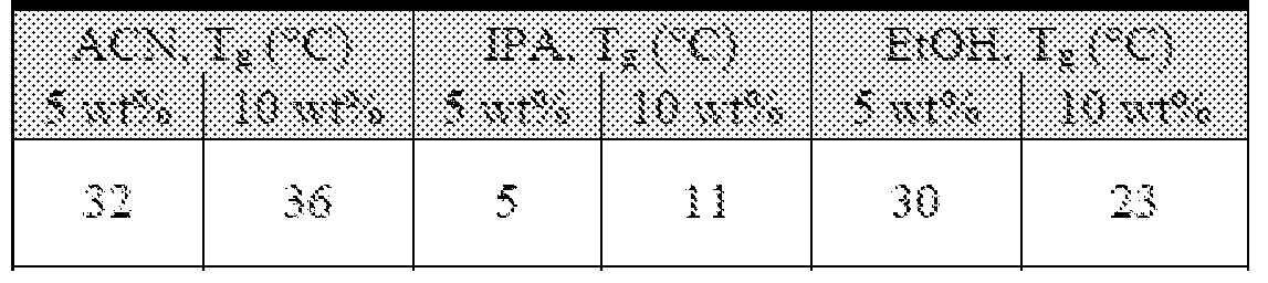
After showing efficacy in producing microneedles of ideal dimensions and strength, the activity of the BuChE was assessed via the established cholinesterase assay. BuChE films
of 5 and 10 wt% loading were cast and subsequently dissolved in water. Because all films were the same size and had the same loading of BuChE, absolute activity was used to determine the effect of each solvent. Results of this study can be seen in Table 11. While the IPA films were shown to exhibit the highest activity, it was not a candidate for microneedles due to the poor mechanical properties of the films; the study did identify IPA as the ideal harvesting solvent for the water-soluble BuChE PRINT particles after manufacturing. The results of both the thermal analysis and activity assays confirmed that ACN was best the casting solvent for microneedles made with water-soluble PRINT particles.
Table 11 : Absolute activity of BuChE recovered from films cast in EtOH, IPA, and EtOH

4.2.1.2 Loading of Particulate BuChE
In order to develop a prophylactic administration of BuChE that would be effective against organophosphate poisoning, long circulation times and controlled release of BuChE would be necessary.1'2'6'7 The quick burst release of the free enzyme would not provide the sustained release via microneedle administration, but BuChE incorporated into PRINT particles has great promise to do so through "depot" microneedles. Particulate formulations offer the potential for use as a prophylactic; this is achieved by delivering long circulating particles with stimulus triggered enzyme release upon gas overexposure. The rapid dissolution of the PVP microneedles would quickly introduce these particles to the body, allowing for the controlled release of the BuChE cargo over time. The fabrication of protein particles has been previously optimized with the model protein bovine serum albumin; using these guidelines, the DeSimone Lab was successful in manufacturing 1 μπι PRINT particles composed of 90% active tetrameric BuChE.17 A representative scanning electron micrograph of these particles can be seen in Figure 52. To increase particle water stability - and therefore open the door to tunable BuChE release - the particles need to be stabilized via a tunable crosslinker. Initial
studies to optimize the crosslinking procedure employ a disuccinimidyl suberate (DSS) linker, rendering them water-insoluble; half of the particles for these studies were crosslinked in this way while the rest remained unmodified.
Particles including BuChE tagged with AlexaFluor 488 probe were incorporated into the ACN pre-microneedle solution at a loading of 5 wt%; crosslinked and non-crosslinked particles were encapsulated into separate devices. Film homogeneity was confirmed via confocal microscopy (Figure 53). Therefore, microneedles were fabricated at the standard conditions for protein cargos (77-83 °C nip temperature) with both particle compositions. ESEM and confocal images of the resulting microneedle devices can be seen as Figure 54. Consistent with the film results, both types of particles showed homogenous distribution in the microneedles, showing the efficacy of PRINT microneedles to load even micron-sized cargo.
To assess the activity of the BuChE release from the particles after microneedle fabrication, patches with non-crosslinked particulate cargo were dissolved in water postprocessing; a solid-state pre-microneedle film of the same composition was also prepared as a control. The aqueous environment both releases the particles from the highly water-soluble PVP matrix and dissolves the non-crosslinked BuChE particles themselves. These solutions were run on the afformentioned cholinesterase assay, and it was seen that BuChE released from the patches retained 50-60% of the activity loaded into the original film. Future studies included the assessment of the unconsumed film to determine the true percent recovered activity of the BuChE after processing; the material loss likely accounts for the activity loss observed. Still, these results indicate PRINT microneedles may be used to deliver active BuChE in particulate form transdermally.
It was also of interest to discern if the crosslinked particles retained their size and shape after release from PRINT microneedles. The DSS crosslinker is employed to provide long term stability of the particles in water, resulting in incredibly slow release kinetics;
therefore, any morphological changes to the particles would be due to the microneedle manufacturing itself. After processing, microneedles loaded with these particles were dissolved in water, and PVP was removed via centrifugation; a solid-state film of the same composition was also processed to serve as a control. Particles were resuspended in IPA for
SEM imaging (Figure 55). Pristine particles were recovered from both the film and microneedles, indicating that our processing does not inherently harm particle morphology. Moving forward with these studies, cleavable crosslinkers will be employed to tune the enzyme release kinetics from the particles, and the delivery of the particles to ex vivo tissue via PRF T microneedles will be investigated.
4.2.2 Ex Vivo Permeation Studies with Microneedles Incorporating Free BuChE
Next, microneedles loaded with 20 wt% free BuChE were applied to ex vivo murine tissue to assess the ability of the devices to adequately penetrate skin and release their cargo. With the aid of the Franz diffusion cell apparatus (Chapter 3), studies of this large protein were performed identically to those with the model proteins, OVA and aldolase, to directly compare their efficacy and release kinetics. The tetrameric equine BuChE used (Mw = 340 kDa, pi = 4.2-4.9) has an isoelectric point very similar to OVA (pi = 4.6) but a mass much larger than even the aldolase (Mw = 161 kDa). Therefore, the major influence on protein skin permeation (size v. isoelectric point) can be examined through studies with this therapeutic enzyme, and significant progress towards the ideal microneedle device for nerve agent scavenging will be made.
To perform these studies, microneedles loaded with 20 wt% of the AlexaFluor 488- tagged enzyme were fabricated, and their dose was determined via quantitative fluorescence imaging on an IVIS Kinetic system. Franz cell permeation studies were then performed utilizing the procedure optimized on drug surrogate proteins. To summarize, microneedle patches were applied to murine skin excised from the back of a nude mouse, holding pressure for 10 seconds (s). After 8 minutes (min), the patch backing was dissolved with water and the skin surface was wiped clean. Skin was then affixed to the Franz cell apparatus to serve as the membrane. Samples of the receptor fluid, phosphate buffered saline (PBS), were taken at regular intervals over 24 h. At the conclusion of the studies, a standard fluorescence plate reader was used to determine the mass of BuChE that transversed the skin at each time point detecting (emission = 550 nm).
The results of these studies can be found as Figure 56. Seen in Figure 56A, less than 3% of the BuChE cargo loaded into microneedle devices was shown to permeate the skin at 24 h. For reference, the BuChE release profile is compared to both drug surrogate proteins in
Figure 56B. This slow diffusion is likely due to the size of the protein, not its pi; the 45 kDa OVA with the same pi was seen to deliver nearly six times more protein over this duration. The tetrameric BuChE also released much slower than the 161 kDa aldolase, supporting that protein size plays a significant role in tissue penetration.
Upon cell termination, the skin treated with BuChE microneedles was fixed, cryosectioned, and imaged on the upright fluorescence/brightfield microscope to map the location of the enzyme in the skin after 24 h. A representative image from these studies (Figure 57) shows the fluorescent BuChE clearly visible below the surface of the epidermis; however, the shallow depth of penetration after 24 h confirms the slow permeation of the protein through murine skin. As with other large cargos, longer studies in vivo are required to observe any increase in permeation over time and to determine how the enzyme interacts with live tissue.
4.2.3 In Vivo Studies with High Activity Free BuChE Microneedles
To determine the ability of PRINT microneedles loaded with free BuChE to introduce enzyme into systemic circulation, patches with very high activity BuChE (>200 U/mg) were optimized for in vivo studies with nude mice. In this way, we can optimize the detection of BuChE in murine serum at longer time points via the activity assay; to assure the highest chance of detection, the high activity BuChE was not tagged with a fluorophore. The experimental parameters for the first pilot study performed can be seen in Table 12 (n = 3). Four time points were selected merely to probe the possible window of detection (up to 48 h). Due to the high expense and low availability of 200 U/mg BuChE, the same three mice were used for the 4 and 24 h time points, and three mice were used for the 8 and 48 h time points; at the shorter time point, blood was drawn from the mouse via submandibular bleeds performed with the aid of the UNC animal core. Terminal blood was collected via cardiac puncture.
Table 12: Study parameters for the in vivo detection of BuChE in circulation after treatment with microneedles

Microneedle application to the back of these animals had been previously optimized for small molecule drug surrogates (Chapter 3). To review, after anesthetizing the mice with isoflurane, microneedle patches were "rolled" onto the skin of the mouse, and pressure (gentle "force of thumb") was applied for 1 minute. After application for 8 minutes, water was applied to the patch's water-soluble backing and allowed to dissolve for (approximately 2-3 minutes). The skin is then wiped clean with medical wipes.
The change in cholinesterase levels (U/mL) in the serum of mice after microneedle application (at each time point) can be seen in Table 13. Baseline cholinesterase levels were taken prior to microneedle administration and have been subtracted out; standards prepared by dosing BuChE to murine serum showed a linear increase in activity with an increase in enzyme concentration. At the conclusion of this in vivo study, the serum from the mice at each time point did not show any statically significant increases in BuChE levels due to the administration of the microneedles. All time points behaved similarly, indicating the microneedle administration did not transport the BuChE to the blood at these sampling intervals.
Table 13: Change in cholinesterase activity after high activity BuChE microneedle administration in vivo, as determined by the UNC Histology Core.

4.3 Summary
In this work, we have fabricated rapidly water-soluble PVP PRINT microneedles that homogeneously encapsulate 20-25 wt% free BuChE. The activity of the enzyme after processing has been confirmed. Additionally, 1 μπι PRINT particles composed of 90% tetramenc BuChE have been fabricated via a melt-solidification process. Both crosslinked and non-crosslinked particles have been incorporated into PVP microneedles at a 5 wt% loading. While the crosslinked particles were found to be intact after microneedle fabrication and release in aqueous solution, the non-crosslinked particles released active enzyme upon dissolution. Finally, the permeation kinetics of the large protein through ex vivo murine tissue were seen to be very slow, and highly active enzyme was not detectable in murine serum after the administration of these microneedles in vivo. Therefore, to ensure rapid systemic exposure of this protein, new microneedle geometries must be explored.
4.4 Experimental
4.4.1 Microneedle Cargo Preparation
4.4.1.1 Fluorescent BuChE
For select patches, BuChE was tagged with a fluorophore prior to microneedle encapsulation. Low activity (-20 U/mL) tetrameric equine BuChE (Aldrich) was tagged with an either NHS-fluorescein (Thermo Scientific) or AlexaFluor 488 NHS Ester (Life
Technologies). BuChE in phosphate buffered saline (PBS) was mixed with the selected probe
(in dimethylformamide) at a 3 : 1 molar excess of dye and allowed to mix for 1 h at RT. The tagged protein was separated from the unreacted dye via centrifugal filtration with a 100 kDa filter (Millipore) at 14,000 RPM at 4 °C for 25 min. The protein concentration was determined via absorption at 280 nm (Nanodrop 2000) through the extinction coefficient (Ei% = 6.39). The tagged protein was dialyzed overnight using a 20 kDa molecular weight cut-off dialysis device (Thermo Scientific) at RT before further use.
4.4.1.2 1 μιη BuChE PRINT Particles
Protein particles were fabricated via small-batch PRINT processing utilizing a melt- soli dification approach. Thin PFPE molds for the fabrication of 1 μπι particles were obtained from Liquidia Technologies. Particles were fabricated at a controlled relative humidity of 30- 35%. A 10 wt% solids pre-particle solution was prepared in water; a solid composition of 2: 1 : 1 BuChE:lactos:glycerol (wt%) was optimized. Of the utilized BuChE, 3 wt% was tagged with AlexaFluor 488 NHS Ester (Life Technologies) as previously described. Films were cast onto poly(ethylene terephthalate) (PET) sheets with a #1 Mayer rod (R.D. Specialties). To assure solvent evaporation, films were exposed to hot air derived from heat guns during casting. After setting for 30 seconds, mold was applied to the film then laminated with a nip temperature of 77-82 °C under 100 PSI pressure. Mold was split from the delivery sheet upon exiting the laminator. A Plasdone (Luvitec VA64, BASF) layer was laminated to the mold before harvesting manually in IP A. Particle suspensions were passed through a 10 μπι filter to remove any large particulates before centrifugal washing (MiniMouse II Microcentrifuge, Denville Scientific at 6,000 g for 3 min) three times in IPA.
Crosslinked particles were prepared as follows: particles were centrifuged to create a pellet and the supernatant IPA was removed. Crosslinker solutions (10 mM) of disuccinimidyl suberate (DSS, Pierce Protein Biology) in ACN were prepared. Particles were resuspended in this ACN solution at a concentration of 1 mg/mL. The reaction was mixed on a benchtop shaker (1400 RMP, 37 °C) for 3 h. Particles were collected via centrifugation (MiniMouse II Microcentrifuge, Denville Scientific at 6,000 g for 3 min) and washed in fresh ACN three times before incorporation into microneedle devices.
The particles were characterized via thermal gravimetric analysis (TGA) (TA Q5000) for concentration determination and imaged via scanning electron microscopy (SEM) (Hitachi
model S-4700) for size and shape confirmation. Samples for SEM were prepared by spotting 1 μΙ_, of -0.5 mg/mL particle solutions in IPA onto a silicon wafer and drying under heat. It has also been determined that the protein content in the particles measured at more than 90% BuChE post-fabrication via cholinesterase activity compared to the theoretical loading (UNC Histology Core, see 4.3.3).
4.4.2 BuChE Microneedle Fabrication and Characterization
Microneedles were fabricated using an adapted PRINT process, described in detail in Chapter 2.15 All fabrication conditions (77-82 °C nip, 50 PSI) for protein-loaded microneedles were employed for the fabrication of BuChE microneedles. However, the preparation of the pre-microneedle solutions varied with BuChE form. All aqueous solutions of free BuChE (tagged, low activity, and high activity) were composed of 0.0002-30 wt% protein in PVP (15-20 wt% solids). Free BuChE incorporated into all organic solvents (ACN, IPA, and EtOH) was done at a loading of 5-10 wt% protein in PVP at 40 wt% total solids. Particle loading was consistent at 5 wt%, employing an ACN casting solvent again at 40 wt% total solids.
Microneedle patches and films were characterized with ESEM (FEI Quanta 200), confocal microscopy (Zeiss LSM 700), and brightfield macroscopy (Leica-Wild M420 Macroscope). Thermal properties of the microneedle films were determined via DSC (Q200, TA Instruments) after storage at 30% relative humidity. Prior to differential scanning calorimetry, decomposition experiments were done by heating 5-10 mg of substrate from 0- 550 °C at 10 °C/min via thermogravimetric analysis (PerkinElmer Pyris 1), and the 95% decomposition temperature was found. The upper temperature limit for the DSC experiments was to be no more than 50 °C lower than the 95% decomposition temperature for each material. DSC was used to determine the Tg's of the substrates. Samples (5-10 mg) were crimped into aluminum pans and heated from -20 °C to 100-120 °C at a rate of 5 °C/min, cooled at a rate of 10 °C/min to -20 °C, and heated again in a second cycle. Tg's were determined from the second heating cycle.
4.4.3 Cholinesterase Assay
BuChE activity for all samples (materials dissolved in water and whole murine blood) were performed at the UNC Hematology Core via the VITROS CHE TE assay (Ortho Clinical Diagnostics). All measurements were taken in accordance to manufacturer specifications.23 Briefly, slides coated with butyrylthiocholine (290 μg) and potassium ferricyanide (180 μg) were acquired and incubated to body temperature (37 °C). A 10 μΙ_, aliquot of sample was spotted onto the slide and allowed to incubate for 5 min. Active BuChE in the samples reacts with the butyrylthiocholine on the slide, producing thiocholine and butyrate. The thiocholine subsequently reduces potassium ferricyanide to potassium ferrocyanide. Color loss due to this reaction was monitored via reflectance spectrophotometry (VITROS DT60) at 400 nm, and the rate of change has been shown to be proportional to the cholinesterase activity of the samples. Any samples above the upper limit of the dynamic range of the assay (0.20-12.50 U/mL) were diluted and reassessed.
4.4.4 Assessment of Particle Morphology after Microneedle Encapsulation
Crosslinked particles were used exclusively for these studies; solid-state films and microneedle patches were made and characterized as previously described. The materials were then dissolved in 1 mL of water to release the particles from the PVP microneedle matrix. Residual PVP was removed via centrifugation (MiniMouse II Microcentrifuge, Denville Scientific at 6,000 g for 3 min) and washed in fresh IPA three times before preparation for SEM as described above.
4.4.5 Permeation Studies with a Franz Cell Apparatus
The permeation kinetics of BuChE through full thickness murine skin were assessed on ex vivo murine skin via a Franz diffusion cell apparatus. All experiments were conducted identically to the studies on protein drug surrogates, described in detail in Chapter 3. To summarize, fluorescently labeled BuChE microneedles were images with an IVIS Kinetic imager (Caliper Life Sciences) to determine patch dose. Due to the AlexaFluor 488 tag, an excitation of 465 nm and emission of 520 nm was used for all patches. The microneedles had to be applied to the skin before affixing the tissue as the membrane. Microneedle patches were applied with the gentle force of thumb, followed by the subsequent dissolution of the
back of the patch. After the substrate dissolved, non-stick medical wipes (Walgreens) were used to wipe the surface of the skin clean. Franz diffusion cells (PermeGear) with a 5 mL receptor compartment and a 15 mm opening were incubated at 37 °C; PBS (Sigma) was utilized as the receptor solution. Samples of the receptor fluid were taken at eight time points over 24 h, immediately replacing the receptor fluid with an equivalent volume of 37 °C PBS. The determination of BuChE mass delivered to in the receptor fluid was found using a standard plate reader at 550 nm, correlating fluorescence to a standard curve prepared in PBS.
Upon cell termination at 24 h, the skin was removed and immediately placed into fixative (2% PFA, USB) for two hours before storage in a PBS solution stabilized with 15% sucrose. Fixed skin was embedded with Tissue-Tec® Optimum Cutting Temperature medium, and cryosectioned identically to those for the all penetration studies. The 12 μπι skin sections were exposed briefly to FROZEN-FIX (Cancer Diagnostics), coverslipped, and imaged via both the fluorescent and brightfield channels of an upright microscope (Olympus BX61 Upright Microscope). Overlays of the fluorescence and brightfield images were obtained and constructed in Velocity (Improvision).
4.4.6 In Vivo Application of High Activity BuChE Microneedles to Nude Mice
Microneedle patches were tested on nude murine skin in accordance with the animal use protocols approved by the UNC Institutional Animal Care and Use Committee (IACUC). Six male nude (nu/nu) mice (6 weeks old) were bred by the UNC animal core facility, and submandibular bleeds were performed prior to microneedle application to establish baseline cholinesterase levels. Approximately 50-100 μΙ_, of serum was collected from each bleed and loaded into serum-separator tubes (BD MicrotainerTM Capillary Blood Collector and BD MicrogardTM Closure, Fisher Scientific). After serum collection, the solutions were stored at -20 °C until core analysis. It has been previously shown in our laboratory that BuChE remains active in serum after this freeze/thaw cycle.
Microneedle patches loaded with high activity tetrameric BuChE were utilized for all experiments; the theoretical dose of the BuChE per patch was 77.5 U, assuming an activity of 200 U/mg. Mice were anesthetized with isoflurane (Baxter) via continuous flow through nose cones and placed on a 37 °C stage. Microneedle patches were rolled onto the skin on the back of the animals (n = 6), and pressure was applied for 1 min. After 8 min, the substrates were
dissolved with water, and the surface of the skin was wiped clean. Mice were then taken off anesthesia and monitored until serum collection.
At selected points (4, 8, 24, or 48 h) after microneedle patch administration, the mice were bled for serum collection with the assistance of the UNC Animal Studies Core. Of the six mice dosed, three were bled at 4 and 24 h, and three were sampled at 8 and 48 h. Blood was collected via submandibular techniques at 4 and 8 h. Before terminal collection (24 and 48 h), mice were administered a ketamine/dexmedetomidine blend to deeply anesthetize the animal prior to cardiac puncture for blood collection. Serum was extracted from whole blood via separator tubes and stored at -20 °C prior to cholinesterase testing (UNC Histology Core).
4.5 References
(1) Chilukuri, N.; Duysen, E.; Parikh, K.; diTargiani, R.; Doctor, B. P.; Lockridge, O.;
Saxena, A. Mo I. Pharmacol. 2009, 76, 612-617.
(2) Darvesh, S.; Hopkins, D. A.; Geula, C. Nature Rev. Neuroscience . 2003, ¥, 131-138.
(3) Pandit, V.; Seshadri, S.; Rao, S. N.; Samarasinghe, C; Kumar, A.; Valsalan, R. J Emerg Trauma Shock. 2011, 4, 132-134.
(4) Yurumez, Y.; Durukan, P.; Yavuz, Y.; Ikizceli, I; Avsarogullari, L.; Ozkan, S.;
Akdur, O.; Ozdemir, C. Intern. Med. 2007, 46, 965-969.
(5) Eskenazi, B.; Bradman, A.; Castorina, R. J Environmental Health Perspectives. 1999,
107, 409-419.
(6) Gaydess, A.; Duysen, E.; Li, Y.; Gilman, V.; Kabanov, A.; Lockridge, O.; Bronich, T.
Chemico-Biol. Int. 2010, 757, 295-298.
(7) Duysen, E. G.; Lockridge, O. Chemico-Biol. Int. 2008, 175, 119-124.
(8) Protein Data Bank. Human monomeric butyrylcholinestrase. http://www.rcsb.org/pdb (accessed Jan 6, 2015).
Naik, R. S.; Pattabiraman, N.; Patel, K. A.; Doctor, B. P.; Saxena, A. Chemico-Biol. Int. 2013, 203, 24-29.
Teng, T. L.; Harpst, J. A.; Lee, J. C; Zinn, A.; Carlson, D. M. Arch. Biochem.
Biophys. 1976, 176, 71-81.
Chatonnet, A.; Lockridge, O. Biochem. J. 1989, 260, 625-634.
Moorad, D. R.; Luo, C; Saxena, A.; Doctor, B. P.; Garcia, G. E. Tox. Methods. 1999, 9, 219-227.
Donnelly, R. F.; Singh, T. R. R.; Morrow, D. I. J.; Woolfson, A. D. Microneedle- mediated Transdermal and Intradermal Drug Delivery ; John Wiley & Sons, Ltd. 2012.
Escobar-Chavez, J. J.; Bonilla-Martinez, D.; Villegas-Gonzalez, M. A.; Molina- Trinidad, E.; Casas-Alancaster, N.; Revilla- Vazquez, A. L. J. Clin. Pharmacol. 2011, 51, 964-977.
Moga, K. A.; Bickford, L. R. ; Geil, R. D.; Dunn, S. S.; Pandya, A. A.; Wang, Y.; Fain, J. H.; Archuleta, C. F.; O'Neill, A. T.; DeSimone, J. M. Ad. Mater., 2013, 25, 5060-5066.
Kelly, J. Y.; DeSimone, J. M. J. Am. Chem. Soc. 2008, 130, 5438-5439.
Xu, J.; Wang, j.; Luft, J. C; Tian, S.; Owens, G.; Pandya, A.; Berglund, P.; Pohlhaus, P. D.; Maynor, B. W.; Napier, M. E.; DeSimone, J. M. J. Am. Chem. Soc. 2012, 134, 8774- 8777.
Xu, J.; Luft, J. C; Yi, X.; Tian, S.; Owens, G.; Wang, j.; Johnson, A.; Berglund, P.; Smith, J.; Napier, M. E.; DeSimone, J. M. Molecular Pharmaceutics 2013, 10(9), 3366-3374.
Oliveira, H. F. D.; Weiner, A. A.; Majumder, A.; Shastri, V. P. J. Control. Release. 2007, 126, 237-245.
(20) Hern, D. L.; Hubbell, J. A. J. Biomed. Mat. Res. 1998, 39, 266-276.
(21) Muggli, D. S.; Burkoth, A. K.; Keyser, S. A.; Lee, H. R.; Anseth, K. S.
Macromolecules. 1998, 31, 4120-4125.
(22) Chen, J.; Zhao, M.; Feng, R; Sizovs, A.; Wang, J. J. Am. Chem. Soc. 2013, 135, 1093810941.
(23) Ortho Clinical Diagnostics. VITROS DT60. http://www.orthoclinical.com/en- us/ProductInformation/ClinicalLaboratoriesA^itrosDT60/Pages/Overview.aspx (accessed June 13, 2014).
(24) Kochhar, J. S.; Quek, T. C; Soon, W. J.; Choi, J.; Zou, S.; Kang, L. J. Pharm. Sci.
2013, 102, 4100-4108.
(25) Gill, H. S.; Prausnitz, M. R. J. Diabetes Sci. Technol. 2007, 1, 725-729.
(26) Chu, L. Y.; Prausnitz, M. R. J. Control. Release. 2011, 149, 242-249.
PRINT MICRONEEDLES FOR THE TREATMENT OF SKIN-INVADING BREAST CANCERS
5.1
Due to the complex biology of cancer, there is a large diversity in how this class of diseases manifests in a patient. A select number of cancers show skin involvement;
carcinomas specifically are derived from epithelial cells such as those found in the skin.1 Skin involvement can be as minimal as the invasion of the lowest epidermal layer, as is the case in basal cell carcinoma; these cancers are easily treatable by surgical resection, for they show extremely low rates of metastasis.2 Other cancers show considerable involvement with epidermal/dermal junction and the lymphatic vessels in lower dermis, such as squamous cell carcinoma, lantigo maligna melanoma, chest wall recurrent breast cancer, and inflammatory breast cancer (U3C).2"8 Of these, well-established treatment options for carcinomas and melanomas of the skin - including tumor resection, immunotherapy via topical creams,
radiation therapy, and laser therapy - have been highly successful in preventing recurrance.4"5 However, the treatment of locally advanced breast cancers displaying skin involvement is a significant challenge, for intravenous (IV) therapies are unlikely to deposit therapeutics near the dermal lymphatics, and both surgical and radiation options have often been exhausted for these patients.6"8
Specifically, microneedles for the treatment of inflammatory carcinoma of the breast (IBC), the most aggressive form of invasive breast cancer known, could provide an attractive minimally-invasive treatment option. Approximately 1-5% of all breast cancer cases are inflammatory in nature.8 Unlike many breast cancers that present as a lump, IBC dysplastic cells commonly reside in the dermal lymphatics, causing obstruction to lymphatic drainage.6 This causes the tissue to become red and swollen, thus the "inflamed" skin.6 This
morphology, also referred to as "peau d' orange," causes structural changes to the skin at the site of invasion; one such case is shown in Figure 58.9 Most IBC cases are in Stage III or IV at the time of diagnosis and progress rapidly; the 3-year survival rate for these patients is near 40%, much lower than that of patients with non-IBC tumors (85%).7'9'10 Due to the involvement with the lymphatic system, metastases are common among IBC patients.8'9 The infrequency of cases has led to few defined targets for treatment, due to its generally undefined biology and the lack of an identified molecular pathway unique to IBC.11
Much research on IBC treatment has focused on improving systemic therapies, mainly on delivery vehicles that reduce the exposure of toxins to healthy cells. Etrych et al. have developed copolymer conjugates for pH sensitive release of paclitaxel to reduce therapeutic cytotoxicity in mammary carcinomas.12 Additionally, other block copolymer solubilizers, conjugates, and prodrug approaches have been investigated to reduce the side effects of standard therapies.13"15 Targeted therapies, namely the use of monoclonal antibodies to inhibit vasculolymphatic processes, have been recently postulated.11 16 Emerging therapies for epidermal growth factor receptor (EGFR) targets, overexpressed in -30% of IBC cases, have been developed in recent years, including Erlotinib, an EGFR tyrosine kinase inhibitor.11 In spite of these efforts, clinicians recognize the complexity of IBC and have stated that prognosis of these patients remains poor.6
As innovative strategies are critical, a novel transdermal -based approach could serve as an avenue for a local and possibly systemic, yet minimally invasive, therapy. Of late, nanoemuslions of tamoxifene citrate applied topically have been investigated for delivery for breast cancer treatment, showing the promise of transdermally applied therapeutics.17 PRINT microneedles loaded with pertinent therapeutics could offer an attractive solution to improve the efficacy of existing IBC therapies while reducing the deleterious effects commonly associated with traditional injections. Herein, we describe the fabrication of PVP
microneedles via PRINT that successfully encapsulate up to 20 weight percent (wt%) docetaxel, a chemotherapeutic routinely used for the treatment of IBC.12 Preliminary animal studies show the ability of the devices to pierce healthy and cancerous tissue, as well as the possibility of microneedle delivery to reduce systemic toxicity.
5.2 Results and Discussion
Docetaxel was chosen as first therapeutic of interest with PRINT microneedles. This small molecule (Figure 59) is a well-established anti-mitotic chemotherapy effective against IBC, and is the standard of care for non-IBC locally advanced cases.18 Initially approved for the treatment of metastatic breast cancer, docetaxel (trade name Taxotere®) is traditionally dosed weekly as a primary systemic therapy.6 18 However, like all chemotherapeutics, it is also cytotoxic to non-cancerous cells.6 Side effects such as alopecia, peripheral neuropathy, fluid retention, and anemia have been observed.18"20 Outside of the standard IV dosing of this taxane, oral formulations have been investigated; poor bioavailability was observed due to first pass metabolism by the liver and intestines.19 The incorporation of this potent chemotherapeutic into PRINT microneedles may localize the toxin to skin, the site of the disease for IBC patients, lowering both the required therapeutic dose and the severity of side effects. Additionally, combination therapies that include microneedle administration are possible.
Ill
5.2.1 Fabrication and Characterization of PRINT Microneedles Incorporating
Docetaxel
5.2.1.1 Fabrication of Docetaxel Microneedles with Multiple Loadings
Due to the hydrophobicity of docetaxel, many approaches to increase the water solubility of this small molecule for IV administration have been researched, including prodrug synthesis and polymeric solubilizers.13'21 However, by introducing the drug in a solid state via microneedles, solubility is no longer an issue. Utilizing amphiphilic PVP as the microneedle matrix, homogenous incorporation of the therapeutic is possible when pre- microneedle solutions are prepared in organics. The composition for docetaxel microneedles was optimized in ethanol for these purposes, easily solubilizing both the PVP and drug. It was found that docetaxel loadings of greater than 20 wt% showed considerable visible phase separation, resulting in crystalline films. The presence of crystallinity in the devices would substantially weaken the matrix, causing the PVP microneedles buckle when applied to the skin.22"25 Therefore, films of 0-20 wt% docetaxel were subjected to thermal analysis
(differential scanning calorimetry, DSC) to observe any non-visible heterogeneity; if crystalline regions were present in the film, a melting endotherm would be present in the scans.
After analysis, it was seen that all films up to 20 wt% docetaxel exhibited no crystalline character; only glass transition temperatures (Tg) were observed. Figure 60 shows the DSC trace for the 20 wt% docetaxel film collected from the second heating cycle. The absence of a melting endothermic peak indicates that these blends remain amorphous.
Additionally, the glass transition temperatures of the films were recorded for all loadings (Table 14). The Tg's were slightly dampened by the incorporation of docetaxel; generally, an increase in loading linearly decreased the glass transition temperature. Up to 20 wt%, however, the temperatures were still around 40 °C; the protein microneedles, displaying similar Tg's, were shown to pierce skin with these characteristics. Therefore, docetaxel films with a loading up to 20 wt% were optimized for microneedle fabrication.
Table 14: Glass transition temperatures (Tg) of the PVP pre-microneedle films loaded with docetaxel.

Microneedles were then made via PRINT with these loadings, utilizing the procedure for the fabrication of blank PVP microneedles reported in Chapter 2. Briefly, solid-state microneedle films were applied to PRINT molds in an isolated area for the processing of chemotherapeutics. Patches were sent through a heated nip at 105 °C to fill the mold, and microneedles were harvested onto flexible backing layers. Figure 61 shows representative environmental scanning electron microscopy (ESEM) images of docetaxel loaded microneedles (5 wt%), showing dimensions consistent with all PRINT systems.
5.2.1.2 Characterization of Microneedle Dose via High Performance Liquid
Chromatography
For all drug surrogates investigated previously, quantitative fluorescence allowed for the non-destructive determination of cargo dose in each individual microneedle patch in its solid-state; however, docetaxel was not amenable to tagging. Therefore, the development of a new method to assess loading was required to accurately determine patch chemotherapeutic dose. In this vein, we aimed to discern the percent by weight of docetaxel in the final device at each loading. By confirming that the patches of each dose consistently have the same wt% docetaxel, individual patches can be non-destructively massed prior to dosing, allowing for accurate dose determination for in vivo studies.
Because the microneedle devices are made exclusively of PVP and docetaxel, accurately quantifying the mass each will allow for the determination of the wt% docetaxel in the final microneedle devices. This can be simultaneously achieved through by via high performance liquid chromatography (HPLC) separations. The quantification of both the agents, separately, has been reported on standard HPLC systems utilizing ultraviolet (UV) detection at 200-250 nm and a common reverse phase (C18) column.26,27 A method that separates the PVP from the docetaxel with high resolution is desired to allow for minimal
sample preparation; in this way, sample microneedle patches could be dissolved, and without further treatment, subjected to quantitative HPLC analysis.
Herein, we report the development of an HPLC method for the separation and quantitation of PVP (average Mw = 10 kDa) and docetaxel; the parameters can be found in Table 15. Due to the polar amide groups on the PVP backbone, there is a large difference in hydrophobicity between the polymer and hydrophobic drug, making efficient separation possible. The molecular weight distribution of the polymer, however, results in a very broad peak that is likely to overlap with the docetaxel at short times. To overcome this limitation, a slow gradient over 45 min was employed, resulting in a peak resolution consistently greater than 1.0. Detection was optimized at 205 nm for both constituents.
Table 15: HPLC parameters for the separation and quantification of PVP and docetaxel

Standardization of the method was performed in accordance with the conditions found in Table 15. PVP and docetaxel standards (in ethanol) were prepared in a single vial at a ratio of 1 :20 to best reproduce the conditions of microneedles loaded at 5 wt%. PVP and docetaxel were seen at a retention time of 14.3 and 27.0 minutes, respectively (see Experimental, Figure 65); as expected, peak width for the PVP standards averaged 21.3 min, while tight docetaxel peaks were 1.0 min in width, on average. PVP calibration curves were highly linear in the concentrations relevant to the microneedle patches; the dynamic range used was 10 mg/mL to
0.15 mg/mL. The same was observed for docetaxel, quantifiable from 1 mg/mL to 0.007 mg/mL. All curves were linear to an R2 value of 0.99 or greater.
To test this method before analyzing sample microneedle patches, solid-state pre- microneedle films cast with five docetaxel loadings, 1-20 wt%, were prepared for analysis. Films were subsequently dissolved in ethanol, and the solutions were injected to the HPLC without further preparation. Peaks at 14.3 and 27.0 min - corresponding to the PVP and docetaxel, respectively - were observed in the chromatograms (see Experimental, Figure 65). Concentrations of the PVP and docetaxel were calculated through the standard curves and normalized to mass.
The wt% docetaxel in the film determined by dividing the mass of the
chemotherapeutic recovered by the total mass of both constituents in the device (Table 16). As anticipated, the wt% docetaxel observed in the films correlated to the amount loaded. Next, the analysis was repeated for PR NT microneedle patches fabricated at the same loadings. Table 16 shows that the final microneedle docetaxel loading is nearly identical to the wt% charged. These results prove that the mass of each patch can be taken before use and docetaxel dose can be reliably calculated on a per-patch basis. In addition, the consistency of the cargo wt% loading between the film and devices indicates that the docetaxel is
homogenously distributed in the needles after PRINT fabrication. Had the cargo shown a preference for the mold or delivery sheet, it is likely the wt% loading would be considerably altered, for the docetaxel would be localized in either the devices or the unconsumed film.
Table 16: Chemotherapeutic loading of PVP/docetaxel blends. Pre-microneedle solution wt% represents the actual percent charged to the materials. Loading in the solid-state films and microneedles was determined via HPLC (n = 3).
5.2.2 In Vivo Maximum Tolerated Dose (MTD) Studies with Docetaxel Microneedles
Next, optimized microneedle devices were applied to nude mice in vivo to down-select a device loading for further studies with tumor models. The maximum tolerated dose (MTD) is defined as the maximum dose of a drug that will result in a therapeutic effect without causing unacceptable toxicity. The microneedles have the possibility to deliver a large local dose to the skin of a mouse, and the ability of the animals to tolerate these doses locally is not understood. It is possible that the microneedles with high loadings (such as the 20 wt% needles) would cause significant adverse effects to the animals due to the burst release of a high mass of docetaxel to the skin; local effects such as burning of the skin may occur.
Neutropenia, characterized by reduced white blood cell counts (WBC), is likely with docetaxel if an overload of the drug reaches the system.7 In addition, animal weight loss is indicative of chemotherapeutic poisoning.
In this case, we aim to determine the highest loading of docetaxel into a microneedle patch with a surface area of 1 cm2 that would be tolerated by the animal over the course of four weekly treatments with the patch. Therefore, we executed the study outlined in Table 17. Initial toxicity was determined with non-tumor-bearing animals. Patch application was optimized over the mammary fat pad of the mouse, the site of a breast tumor in murine models. All conditions for application (1 min of pressure, 8 min incubation time before substrate dissolution) were executed identically to the studies described in Chapters 3 and 4. The skin was wiped clean with medical wipes; any removed docetaxel was extracted from the wipes to determine the delivered dose. This was done by subtracting the amount of chemotherapeutic removed from the skin from the mass of drug in the original patch (as described in 3.4.6). The mass dosed, on average, with each loading can be seen in Table 18. One week before dosing, baseline bloodwork was performed by the UNC Hematology Core to determine native white blood cell, red blood cell, lymphocyte, granulocyte, monocyte, and platelet count in whole blood. Blood was drawn every two weeks to observe any changes in these counts due to microneedle treatment.
Table 17: Study parameters for the determination of the MTD of patch-administered docetaxel to the skin

Table 18: Average dose delivered with docetaxel per patch loading with a 1 cm2 array

Visually, as seen in Figure 18, skin burning was not observed for any of the mice after 4 weeks of treatment. The skin morphology of the region treated with microneedles and the contralateral skin appeared identical, which indicated no local burning effects of the treatment. In addition, mice continued to gain weight over the treatment and up to one month after the last dose (at the time of sacrifice), showing no inhibition in growth due to the systemic toxicity of the chemotherapeutic. Finally, it was determined that all red and white blood cell counts were not altered significantly from the native levels. Seen in Figure 63, levels for all parameters assessed did not fluctuate in a dose-dependent manner. Therefore, it can be concluded that even our largest dose (20 wt% microneedles) did not cause severe toxicity, and are under the MTD for transdermal administration on non-tumor bearing animals.
It is postulated, then, that the chemotherapeutic administered to the skin was either localized to this barrier for the duration of the study or entered systemic circulation at levels
that did not cause toxicity. To accurately determine where the drug has gone, biodistribution studies on the transdermal application of docetaxel via PRINT microneedles must be done. Currently, the largest barrier to performing this analysis is the difficulty in quantifying absolute drug concentration in excised skin. While assays have been developed for the detection of docetaxel in many tissues - including tumor, liver, kidney, and other internal organs - utilizing sensitive mass spectrometry, they have not been adapted to skin.21 18 The dense collagen matrix and rigid keratinocytes found in skin have been shown to limit the effectiveness of tissue homogenization with this epithelium. Translating these assays to skin would be of highest priority to determine the ultimate delivered dose of docetaxel to the skin; in this way, microneedles efficacy as well as the biodistribution of the drug over time could be assessed.
5.2.3 Optimization of Microneedle Administration to Tumor-bearing Mice
Concurrent to the determination of the PRINT microneedle MTD in non-tumor bearing mice, we aimed to optimize the application of a device to a mouse expressing IBC tumors due to changes in skin morphology expressed with the disease. However, tumor models for IBC are scarce, and the few that have been developed have considerable advantages and disadvantages.29"33 The "inflammatory" phenotype is accurately expressed in the human derived xenograft model MARY-X, growing exclusively in the dermal lymphatics and blood vessels.29 Alpaugh and co-workers, the developers of the line, observed that MARY-X not only induced erythema in murine skin, it also lead to a high rate of pulmonary metastasis, commonly observed in the clinic.29 However, this model is not readily available, limiting studies performed with these cells. Other lines shown to have some level of lymphatic involvement include SUM102, SUM190, SUM149, and FC-IBC02.30-33 SUM149 is considered triple-negative [i.e. the cells lack the overexpression of the three most common receptors: hormone epidermal growth factor receptor 2 (HER-2), estrogen receptor (ER), and progesterone receptor (PR)], making these cancers extremely hard to treat because many targeted therapies cannot be employed.32 33 This patient-derived IBC cell line is known to demonstrate the "inflammatory" phenotype in some cases, but can also present as a solid tumor; even with identical injection protocols, a high variability of morphologies has been
observed. This model is readily available and is, consequently, the most widely used cell like in IBC research.30 Therefore, the SUM149 line was selected for study.
PRINT microneedles were then administered to the skin of mice with SUM149 tumors. Cells were grown in the DeSimone lab and injected into the mammary fat pad of 5- week-old female nude mice. Tumor volumes were monitored over 1 month, and volumes of 90-200 mm3 were reported at the time of microneedle application. Of note, all mice studied displayed solid tumors; the inflammatory phenotype was minimized, for only light red inflammation was observed on the skin of the mice. Patches (20 wt% docetaxel) were fabricated with a surface area of 1 cm2 and administered to the skin directly above the tumor on the flank of the mouse. As seen in Figure 64, the flexible arrays were able to conform to the skin around the tumor mass of small volumes (-100 mm3). The microneedles were able to penetrate the skin, but delivery into the tumor cannot be achieved with the 400 μιη tall needles when the cancer presents as a lump. Moving forward, longer microneedles may be required to achieve efficacy in the SUM 149 model due to the lower dermal skin involvement, and even solid tumors, observed during this study.
5.3 Summary
In this work, we described preliminary work with PRINT microneedles for the treatment of inflammatory and chest wall recurrent breast cancers. This novel, transdermal - based approach may fill an unmet need for a local, minimally invasive therapy. PVP microneedles were loaded with docetaxel, a well-established anti-mitotic chemotherapy, up to 20 wt% drug. Chemotherapeutic loading was confirmed via high performance liquid chromatography. In vivo studies on female nude mice with patches of a range of loadings (0- 20 wt%) were performed to establish the maximum tolerated dose via transdermal delivery. It was seen that the delivery of up to 0.85 mg locally (once a week for four weeks) did not cause significant skin morphological changes, affect red and white blood cell counts, or contribute to weight loss. Patches were also administered to mice with SUM149 xenografts, showing that the devices effectively can be applied in the presence of tumors. Moving forward, quantifying docetaxel in vivo is of highest priority to determine the absolute delivered dose of the PRINT microneedle patches, and the fabrication of longer microneedles is desired to penetrate lower into the dermis where the dysplastic cells have been observed. With these
modification, the transition of these devices to biodistribution, pharmacokinetic, and efficacy studies can be achieved.
5.4 Experimental
5.4.1 Fabrication and Characterization of Docetaxel-Loaded PRINT Microneedles
Microneedles were fabricated using an adapted PRINT process, described in detail in Chapter 2.34 All fabrication conditions (105 °C nip, 50 PSI) for blank PVP microneedles were employed for the fabrication of chemotherapeutic microneedles. Due to the cargo toxicity, the preparation of the pre-microneedle solutions was isolated to a controlled region, and all equipment used was exclusively designated for chemotherapeutic work. Pre-microneedle incorporating docetaxel (LC Laboratories) were composed of 0-20 wt% drug in PVP (80-100 wt% respectively) and employed ethanol as the casting solvent. The solutions were optimized at a 30 wt% total solids. Films were dried overnight to allow for ethanol evaporation before PR NT processing.
Thermal properties of the microneedle films were found via DSC (Q200, TA
Instruments) analysis after storage at 20-30% relative humidity. Decomposition experiments were done by heating 5-10 mg of substrate from 0-550 °C at 10 °C/min via thermogravimetric analysis (PerkinElmer Pyris 1), and the 95% decomposition temperature was determined. The upper temperature limit for the DSC experiments was to be no more than 50 °C lower than the 95% decomposition temperature for each material. DSC was used to determine the Tg's of the substrates. Samples (5-10 mg) were crimped into aluminum pans and heated from -20 °C to 100-120 °C at a rate of 5 °C/min, cooled at a rate of 10 °C/min to -20 °C, and heated again in a second cycle. Tg's were determined from the second heating cycle. Microneedle patches were characterized with ESEM (FEI Quanta 200) and brightfield macroscopy (Lei ca- Wild M420 Macroscope).
5.4.2 HPLC Methodology
Docetaxel quantification was performed on an Agilent 1200 LC system coupled with a G316510 UV multiple wavelength detector (MWD) (Agilent Technologies) set to 205 nm. A Zorbax Eclipse XDB-C18 analytical column (Agilent) was employed for all analyses (4.6 x 150 mm, 5 μιη particles). Aqueous (pure water, HPLC grade, Fisher) and organic [55:5
acetonitrile, HPLC grade (Fisher):2-propanol, HPLC grade (Fisher)] mobile phases were mixed. Solvent was pumped through the system on a G1311 A Quant Pump (Agilent) equipped with a degasser at 1.0 mL/min.
Combination PVP/docetaxel standard solution was prepared in ethanol by dissolving 20 mg PVP and 1 mg docetaxel in 1 mL of ethanol (n = 3). Serial dilutions were performed down to a PVP concentration of 0.15 mg/mL PVP and 0.0078 mg/mL docetaxel. Samples were loaded into standard clear glass FIPLC vials (10 mm Screw Thread Vials, Fisher).
Injections of 20 μΐ^ were run on a 45 min gradient (100% water to 100% organic). The column temperature was set at 20 °C. Post-run, peak area was determined in Agilent
ChemStation software. Calibration curves were constructed for each constituent of the run and verified to a R2 value of 0.99 or greater. The dynamic range of each analyte was found to be 10 mg/mL to 0.15 mg/mL for PVP and 1 mg/mL to 0.007 mg/mL for docetaxel. Due to the high doses in the microneedle films, this range was ideally suited for analysis.
Next, solid-state films of 1, 5, 10, 15, and 20 wt% docetaxel in PVP were prepared for analysis by dissolving the entire film (n = 3, -2-3 mg) in 1 mL of ethanol. Samples were not diluted further for analysis. Using the established calibration curves, the concentrations of PVP and docetaxel were determined; absolute mass was determined based upon the mass of the original film before dissolution. This analysis was repeated for microneedle patches of the same compositions (n = 3). Sample chromatograms from the standards, films, and
microneedle patches can be seen as Figure 65.
5.4.3 Maximum Tolerated Dose study with Nude Mice
Microneedle patches were administered to nude mice in accordance with animal use protocols approved by the UNC Institutional Animal Care and Use Committee (IACUC). Female nude mice (4-6 weeks old) were bred by the UNC animal core facility, a total of 15 animals were used, n = 3 for ease dose. With the assistance of the UNC Animal Studies Core, submandibular bleeds were performed 1 week prior to the first microneedle patch dose.
Bloodwork was run immediately by the UNC Hematology Core to determine the white blood cell, red blood cell, lymphocyte, granulocyte, monocyte, and platelet count in whole blood collected in ethylenediaminetetraacetic acid (EDTA)-coated tubes (Milan, USA). The core determined complete blood counts with differential using Heska's blood counter. These levels
were used as the baseline for all subsequent blood draws. Patches of equivalent mass with loading of 1, 5, 10, and 20 wt% with a surface area of 1 cm2 were compared to a control (treatment with PVP microneedles without cargos). The calculated dose/patch for these studies ranged from 0-1.5 mg docetaxel based upon loading and patch mass.
For patch application, mice were anesthetized with isoflurane (Baxter) via continuous flow through nose cones. Microneedle patches were rolled onto the skin on the left flank of the animals, the region where an IBC tumor would be located in tumor-bearing studies, and pressure was applied for 1 min. After 8 min, the substrates were dissolved with water, and the surface of the skin was wiped clean. Mice were then taken off anesthesia and monitored for weight loss and skin rash/burning by the UNC Animal Studies Core. Patch application was done once a week for four weeks. Every two weeks, submandibular bleeds were performed on all animals, and whole blood was delivered immediately on ice to the UNC Hematology core for analysis. Mice were sacrificed for skin collection 1 month after the administration of the last microneedle patch dose. Skin from both the treated area and the contralateral flank were collected, flash-frozen, and stored at -80 °C.
To determine the maximum therapeutic dose that was delivered to the skin via each device, docetaxel was extracted from the medical wipes after patch application. Wipes used to clean the skin for each experiment were left to dry overnight, leaving only solids; the wipes were then placed in 2.0 mL Eppendorf tubes with 1.5 mL of ethanol. After shaking for 1 h at 750 RPM at room temperature, the supernatant solution was removed and loaded into HPLC vials for analysis. Wipes dosed with known masses of docetaxel (as a solution in ethanol) were treated identically and used to form a standard curve, account for the extraction efficiency of the cargo. The peak area of the known docetaxel doses were averaged (n = 3) and used to construct a wipe extraction standard curve (linear to R2 = 0.998). This curve was used to determine the mass of docetaxel removed for the mice and subtracted from the patch loading to determine the delivered dose. It was found that the patches delivered 0-0.85 mg of docetaxel from the loadings of 0-20%.
5.4.4 Administration of Docetaxel-Loaded Microneedles to Tumor-Bearing Mice
All studies with tumor-bearing animals are executed in accordance with animal use protocols approved by the UNC Institutional Animal Care and Use Committee (IACUC).
Female nude mice (5 weeks old) were bred by the UNC animal core facility. A 200 μΐ.
suspension with Matrigel® (Corning) of 5 x 10⁶ SUM149 cells (grown in the DeSimone Lab) were injected into the mammary fat pad of the mice to develop tumor xenografts. Tumor growth was monitored, and tumor volume was calculated using the formula: tumor volume (mm3) = (w2 x l)/2, where w = width and 1 = length in mm as measured by calipers. Tumor volumes of 90-200 mm3 were reported at the time of microneedle application after growth for 1 month.
Patches loaded with 20 wt% docetaxel in PVP with a surface area of 1 cm2 were fabricated for these studies. The device was "rolled" into the skin at the site of the tumor and held under mild pressure for 1 min. Microneedles were visualized in the skin by eye. After 8 min, the patch backing was dissolved. Mice were sacrificed with the assistance of the UNC Animal Core after the skin was wiped clean. Skin from both the treated area and the contralateral flank were collected, flash-frozen, and stored at -80 °C.
5.5 References
(1) National Cancer Institute. What is Cancer?
http://www.cancer.gov/cancertopics/cancerlibrary/what-is-cancer (accessed March 30, 2012).
(2) Raasch, B. Clin. Cosmet. Investig. Dermato. 2009, 2, 65-75.
(3) McKenna, J. K.; Florell, S. R.; Goldman, G. D.; Bowen, G. M. Detmatol. Surg. 2006,
32, 493-504.
(4) Wolf, I. H.; Cerroni, L.; Kodama, K.; Kerl, H. Arch. Dermatol. 2005, 141, 510-514.
(5) Freedman, G. M.; Fowble, B. L. Oncology. 2000, 14, 1561-1581.
(6) Hurley, J.; Reis, I.; Silva, O.; Gomez, C; DeZarraga, F.; Velez, P.; Welsh, C; Powell, J.; Doliny, P. Clinical Breast Cancer 2005, 5, 447-554.
(7) Yang, W. T.; Le-Petross, H. T.; Macapinlac, H.; Carkaci, S.; Gonzalez-Angulo, A. M.;
Dawood, S.; Resetkova, E.; Hortobagyi, G. N.; Cristofanilli, M. Breast Cancer Res. Treat. 2008, 109, 417-426.
Il'yasova, D.; Siamakpour-Reihani, S.; Akushevich, I; Akushevich, L.; Spector, N.; Schildkraut, J. Breast Cancer Res. Treat. 2011, 130, 691-697.
Inflammatory Breast Cancer.
http://www.vci.org/inflammatoiy_breast_cancer_treatment/inflammatorybreastcancertr ea tmentl .htm (accessed Nov 2, 2011)
Fillmore, C. M.; Kuperwasser, C. Breast cancer research. 2008, 10, R25.
Yamauchi, H.; Ueno, N. T. Cancer. doi: 10.1002/cncr.25171. Published Online: May 19, 2010.
Etrych, T.; Sirova, M.; Starovoytova, L.; Rihova, B.; Ulbrich, K. Mol. Pharm. 2010, 7, 1015-1026.
Le Garrec, D.; Gori, S.; Luo, L.; Lessard, D.; Smith, D. C; Yessine, M. A.; Ranger, M.; Leroux, J. C. J. Control. Release. 2004, 99, 83-101.
Liu, J.; Zahed, P.; Zeng, R; Allen, C. J. Pharm. Sci. 2008, 97, 3274-3290.
Delplace, V.; Couvrer, P.; Nicolas, J. Polym. Chem. 2014, 5, 1529-1544.
Zhang, D.; LaFortune, T. A.; Krishnamurthy, S.; Esteva, F. J.; Cristofanilli, M.; Liu, P.; Lucci, A.; Singh, B.; Hung, M. C; Hortobagyi, G. N.; Ueno, N. T. Clin. Cancer Res. 2009, 15, 6639-6648.
Setty, C. M.; Pathan, I. B. Int. J. PharmTech Res. 2011, 3, 288-297.
Heys, S. D.; Sarkar, T.; Hutcheon, A. W. Breast Cancer Res. Treat. 2005, 90, 169- 185.
Chabner, B. A.; Longo, D. L. Cancer Chemotherapy and Biotherapy: Principles and Practice; Lippincott Williams & Wilkins. 2011.
Strother, R. M.; Sweeney, C. Expert Opin. Drug. Metab. Toxicol. 2008, 4, 1007-1019.
Chu, K. S.; Finniss, M. C; Schorzman, A. N.; Kuijer J. L.; Luft, C. J.; Bowerman, C. J.; Napier, M. E.; Haroon, Z. A.; Zamboni, W. C; DeSimone, J. M. Nanoletters., 2014, 14, 1472-1476.
Donnelly, R. F.; Singh, T. R. R.; Morrow, D. I. J.; Woolfson, A. D. Microneedle- mediated Transdermal and Intradermal Drug Delivery; John Wiley & Sons, Ltd. 2012.
Kochhar, J. S.; Quek, T. C; Soon, W. J.; Choi, J.; Zou, S.; Kang, L. J. Pharm. Sci. 2013, 102, 4100-4108.
Gill, H. S.; Prausnitz, M. R. J. Diabetes Sci. Technol. 2007, 1, 725-729.
Chu, L. Y.; Prausnitz, M. R. J. Control. Release. 2011, 149, 242-249.
Jones, S. A.; Martin, G. P.; Brown, M. B. J. Pharm. Biomed. Anal. 2004, 35, 621-624.
Andersen, A.; Warren, D. J.; Brunsvig, P. F.; Aamdal, S.; Kristensen, G. B.; Olsen, H. BMC Clin. Pharmacol. 2006, 6, 2.
Zamboni, W. C; Strychor, S.; Joseph, E.; Parise, R. A.; Egorin, M. J.; Eiseman, J. L. Cancer Chemother. Pharmacol. 2008, 62, 417-426.
Alpaugh, M. L.; Tomlinson, J. S.; Shao, Z. M; Barsky, S. H. Cancer Res. 1999, 59, 5079-5084.
Nokes, B. T.; Cunliffe, H. E.; LaFleur, B.; Mount, D. W.; Livingston, R. B.; Futscher, B. W.; Lang, J. E. J Cancer. 2013, 4, 104-116.
Allred, C; Medina, D. J. Mammary Gland Biol. Neoplasia. 2008, 13, 279-288. Hoffmeyer, M. R.; Wall, K. M.; Dharmawardhane, S. F. Cancer Cell Int. 2005, 5, 11.
Singh, B.; Cook, K. R.; Martin, C; Huang, E. H.; Mosalpuria, K.; Krishnamurthy, S.; Cristofailli, M.; Lucci, A. Clin. Exp. Metastasis. 2010, 27, 233-240.
(34) Moga, K. A.; Bickford, L. R. ; Geil, R. D.; Dunn, S. S.; Pandya, A. A.; Wang, Y.; Fain, J. H.; Archuleta, C. F.; O'Neill, A. T.; DeSimone, J. M. Ad. Mater., 2013, 25, 5060-5066.
SUMMARY
6.1 Subject Matter Described
6.1.1 Fundamental Design Rules of Effective Microneedle Drug Delivery
In recent years, it has been conclusively shown that biodegradable microneedle devices effectively deliver therapeutics to the skin employing safe, compatible materials.1"7 By avoiding metal, silicon, or other insoluble arrays, these devices eliminate biohazardous waste associated with the patch, remove the possibility of accidental needle sticks, and prevent the deposition of materials to the skin that may cause immunogenic
consequences.1'2'8 9 The uses of biodegradable microneedles are numerous, including the delivery of insulin, human growth hormone, vaccine antigens and adjuvants, nanoparticles, and others.1'4 10"13 However, few platforms offer the ability to load cargos of nearly any size, charge, and polarity.1 4 The Particle Replication In Non-Wetting Templates (PRINT) processes allows for highly reproducible microneedle fabrication. Devices made with amphiphilic polyvinylpyrrolidone (PVP) have been shown to encapsulate a wide range of cargos, and the mild processing conditions employed protect fragile cargos.6 We are uniquely able to study the fundamental parameters of effective transdermal delivery with a diverse group of therapeutics and drug surrogates, elucidating the fundamental design rules for transdermal delivery via rapidly water-soluble microneedles.
6.1.1.1 Studies with PRINT Microneedles Employing Current Size and Shape
In this work, we demonstrated the ability of PRINT microneedle devices to efficaciously pierce murine skin and deliver all studied surrogates to ex vivo murine tissue; we observed stark differences in their ability to transport through full-thickness murine tissue in 24 hours (h) though the use of a Franz diffusion cell apparatus. While small surrogates were
shown to permeate effectively at these times, larger cargos (high molecular weight proteins and nanoparticles) did not deliver relevant doses. Extending these studies beyond 24 h would help determine the permeation kinetics of these cargos and, in regards to the nanoparticles, the effect of particle surface charge on transport. However, it has been shown that the integrity of most- including excised skin (murine, porcine, and human), polymeric scaffolds, and cultured model skin - membranes decreases significantly after 24 h, making extended Franz cell experiments less likely to mimic in vivo behavior.14 15
Logically, transitioning in vivo would allow for the systemic study of permeation kinetics at these longer time points. In addition, the ability to observe the cargo in live skin permits the investigation of drug surrogate interaction with cells; for example, the
determination of how nanoparticle surface charge influences cell uptake and transport could be examined. Animals could be sacrificed at many time points after patch application; these time points can be extrapolated using the ex vivo permeation kinetics observed on the Franz cells. Quantitative fluorescence imaging techniques can be employed to determine the biodistribution of cargos at each point, revealing the true permeation kinetics for murine models. The uptake or association of the drug surrogates with different cell types present in the skin - including Langerhans and dermal dendritic cells - can be determined via flow cytometry analysis.
While the drug surrogates studied herein were chosen for their diversity, PVP microneedles have the potential to encapsulate other cargos of interest, such as poly(lactic-co- glycolic acid) (PLGA) nanoparticles.10 It has been shown that PLGA particles of different sizes, shapes, and monomer ratio (lactic acid to glycolic acid) entrap and release therapeutics at different rates; encapsulating a range of these particles in microneedles could allow for the study of "depot" patches, in which the highly water-soluble PVP deposits the sustained release nanoparticle to the skin.16 This is particularly promising due to concerns that microneedles made entirely from a sustained release polymer leave channels in the skin for days that permit pathogen invasion.1 17 The investigation of these microneedles, ex vivo and in vivo, would be particularly attractive for the delivery of therapeutics requiring routine injections, such as insulin or human growth hormone, minimizing the frequency of treatment for these patients.13
At the conclusion of studies in mice, cargos of further interest could be transitioned to studies in Gottingen minipig model to provide relevant pre-clinical data with optimized patches.18 This model is considered the gold standard for pre-clinical trials on transdermal formulations, chosen for its comparable thickness and transdermal permeability to human skin. After initial ex vivo studies, skin histology coupled with the tracking of fluorescently- labeled cargo would allow for a qualitative understanding of the in vivo fate of the drug surrogates. Since large-animal fluorescence imaging is not feasible, quantitative positron emission tomography (PET) imaging using an isotopic tag could be used to determine drug surrogate biodistribution. The University of North Carolina has a state-of-the-art MRI/PET system, one of four systems available nationwide, making these studies manageable on campus.
6.1.1.2 Role of Microneedle Dimensions on Delivery Efficacy
Currently, all PRINT microneedles have made from the same master template, resulting in needles that are -400 μιη tall with an aspect ratio of two. While this size is very promising in murine skin, it was shown that alterations to the microneedle dimensions would be necessary to translate to human application. Additionally, a multitude of studies have shown that microneedle length, tip diameter, aspect ratio, tip-to-tip spacing, and geometry play a large role in the efficacy of biodegradable devices when the microneedle matrix is held constant.1 19"21 In particular, Kochhar et al. have shown that the spacing between
microprojections plays a key role in what percentage of the needle can penetrate into rat tissue; it was shown that a difference of 800 μπι in tip-to-tip spacing can increase the penetration depth from 10% to 80% of the needle height.19 Tip diameters were shown to be of pivotal importance by Davis et al., outlining that needle insertion force increased linearly with increased tip diameter.22 The optimal microneedle design is highly debated; some researchers suggest that microneedles 1 mm in height are necessary to ensure rapid uptake of drugs into the system, while others argue that needles no longer than 200 μπι are ideal.1 20 Therefore, varying the physical dimensions and spacing of microneedles composed of identical materials is necessary to determine the ideal microneedle device for each intended application.
The key limitation to performing these studies with PRINT is the difficulty, expense, and fidelity of microneedle masters attained for molding-based manufacturing. While the
fabrication of metal microneedles is well established and inexpensive, the out-of-plane design often makes it impossible to mold these structures.1 Masters made from silicon via reactive ion etching, electrochemical etching, photolithography, and deep x-ray lithography are all fragile and expensive, requiring a cleanroom environment and many hours of labor.1'6'23,24 Additionally, the standard wafers used to create the silicon structures are 525 μιη thick or less, limiting the resulting microneedle height significantly.1 While photolithography allows for thicker starting films (500-1000 μπι) prepared via spin coating, multiple spin and soft-bake steps are required, creating layered structures prone to flaws.1 Finally, all processes requiring a wet-etch step to remove a material after structure formation limit microneedle tip-to-tip spacing due to the slow rates utilized to avoid mask dissolution.
Recently, light dynamic mask micro-stereolithography, drawing lithography, and two- photon polymerization have been discussed as a way to improve the manufacturing of high aspect ratio microneedles, enabling easy prototyping of microneedle geometries with decreased labor.1 24"28 Stereolithography employs controlled photopolymerization of a liquid resin with high spatial resolution to create a 3D structure, achieved by projecting light onto the build area with a digital micromirror device.24'25 The pattern of the projected light at any given time is constructed by creating an stereolithography (STL) file of the desired
microneedle device, which slices the feature into a number of layers and projects them in sequence.25 Structures with heights in the range of 500-3000 μπι have been reported with this technology; however, the ability to taper the structures to a sharp tip is still a challenge.24 25 Still, layer-by-layer fabrication presents an inherent trade-off between resolution and speed, wherein decreasing layer thickness results in slower manufacturing, due to required separation, recoating, and repositioning steps between each projection. Drawing lithography creates 3D ultrahigh aspect ratio structures by extending a 2D polymeric resin mechanically in the z-direction and solidifying the structures via cooling though the glass transition of the polymer.26 Lee and Jung have optimized this process for the creation of microneedle arrays (Figure 66). Here, an array of pillars is placed on the 2D polymeric resin heated above its glass transition temperature and drawn upward; curing occurs upon cooling. The pillar array is removed, leaving isolated microneedles of ultrahigh aspect ratios. Due to the challenges of molding these masters, this technique has been mainly investigated for the direct fabrication of microneedle devices, eliminating the need for molding altogether.26 One considerable
drawback, however, is the limited control over sidewall profiles afforded by the drawing process.
Lastly, two photon polymerization, a technique in which employs a femtosecond laser to initiate photopolymerization by localizing two photons in time and space, has been employed for microneedle fabrication.27,28 A computer aided design (CAD) file instructs a highly calibrated x,y galvanometric mirror scanner's motion across a glass slide, selectively polymerizing in localized volumes. This process provides exceptionally high temporal and spatial (~nm/layer) resolution.28 Structures up to 1 mm have been created in this way, but the slow processing times limit the technology in terms of rapid prototyping or direct
biodegradable array fabrication.
By employing one of the emerging master fabrication technologies, PRINT microneedles of various dimensions could be manufactured and studied both ex vivo and in vivo. After determining the PRINT microneedle array design that demonstrates the greatest efficacy of therapeutic delivery, large scale production would be required to transition the technology into clinical trials. Therefore, the optimization of the needle dimensions is paramount for each intended therapeutic target in order to advance PRINT microneedles to market.
6.1.2 Optimizing Microneedle Devices for the Effective Delivery of
Butyrylcholinesterase (BuChE) and Chemotherapeutics
Based on preliminary findings, the delivery of free or particulate BuChE via microneedle devices to rapidly into systemic circulation would be challenging with the current design of PRINT microneedles. Investigating new microneedle geometries, therefore, would be of high interest for the delivery of this organophosphate scavenger. Additionally, depositing the enzyme to the dermal layer exclusively may increase the efficacy of the devices, increasing systemic exposure and minimizing local BuChE concentration.
With these aims, we envision microneedle devices that amass BuChE selectively to three skin regions - stratum corneum, lower epidermis, and dermis - though tip-loaded microneedles with heights of 25 μπι, 450 μπι, and 750 μπι. The designs, shown in Figure 67, employ microneedles with 'projectile' tips to selectively target distinct regions of the skin.
Only the 'projectile' tip would contain cargo, allowing for highly specific release that will not contaminate other depths of the skin. The tip would be composed of a rapidly-dissolving, water-soluble matrix (e.g. PVP) for quick release of the cargo in vivo. The remainder of the microneedle could be filled with a water insoluble, biocompatible material (e.g. PLGA) to serve as a mechanical booster to drive the needle to its desired depth; cargo would not be encapsulated in this layer. The shortest microneedles (25 μπι) will be entirely composed of water-soluble matrix and cargo, i.e., the mechanical booster will be absent, for they are designed to target the outermost layer of the skin.
These studies would be most efficacious in animal models with thicker skin, making minipigs the optimal pre-clinical model for the execution of these experiments (see 6.1.1). Down-selection to the optimal microneedle devices will be done via permeation testing on excised minipig skin with the Franz cell apparatus. In vivo studies would be performed on these formulations to determine the ability of the PRINT microneedles to deliver BuChE systemically. Due to the large amount of protein required in systemic circulation for the neutralization of organophosphate overexposure, large patches containing 200-300 mg of BuChE will be designed.29 Utilizing the taller needles (750 um tall), square microneedle patches measuring 3-4 x 3-4 inches are postulated to deliver this dose. PRINT technology enables the fabrication of patches after scale-up to cGMP manufacturing, and the flexible backing layer would allow for such large patches to be administered to the arm. Therefore, by employing PRINT microneedles, great strides may be made towards full body protection against nerve gas exposure utilizing the transdermal route of administration.
To optimize microneedles for the delivery of chemotherapeutics to skin-invading breast cancers, tumor-bearing animal studies must be performed on optimized PRINT microneedle devices with docetaxel. Quantitative assays for the detection of this
chemotherapeutic in animal tissue have been reported; the validation of these methods to skin would be required, for this organ is not typically analyzed during studies with solid tumors.31 Next, patient derived SUM 149 tumor xenografts on nude mice would be utilized to determine the efficacy of transdermally-administered docetaxel in combating the dermal-laden dysplastic cells. Tumor cells grown in the DeSimone Lab would be injected into the mammary fat pad of nude mice, and animals would be monitored for the "peau d' orange" morphology or the growth of solid tumors. Microneedle therapy will be compared to standard
intravenous (IV) treatment as a control. Biodistribution and pharmacokinetic studies will be done to determine the fate of the drug in vivo; minimizing the systemic circulation of the toxic drug would be prioritized.
In select cases, a burst release of locally-delivered docetaxel would not be
advantageous for treatment. Work on the synthesis of lipidized docetaxel using silyl ether chemistry is underway in the DeSimone Lab; incorporating these analogs into microneedles could be promising.33 Shown in Figure 68, these prodrugs have been shown to minimize systemic toxicity and display tunable rates of conversion based on the length of the attached alkyl chain.33 These analogs could reduce the cytotoxicity of the drug to healthy cells and increase exposure throughout the dermal lymphatics. As with the free drug, loading in the needles will be optimized to administer a high dose per patch while maintaining the mechanical strength necessary to pierce the epidermis. The devices will then be applied to ex vivo and in vivo to determine the ultimate efficacy of this approach.
6.2 Summary of Fabrication and Characterization
6.2.1 Fabrication and Characterization of PRINT Microneedle Patches
Microneedles are arrays of micron-sized projections for localized and systemic drug delivery. Considered minimally-invasive, these devices pierce the skin to administer drugs transdermally, creating channels for the passage of a therapeutic without causing pain;
biodegradable microneedles are of high interest due to their low complexity, ability to deliver a wide range of therapeutics, and high levels of safety.1 A main limitation of biodegradable microneedles is their arduous manufacturing that requires vacuum and centrifugation steps to fill a mold.1 Manufacturing microneedles via the cGMP-compliant PRINT platform has great promise to expand this growing field by eliminating these obstacles to clinical translation. Herein, the fabrication of 100% water-soluble PRINT microneedles on flexible substrates has been demonstrated. Their ability to load therapeutics of nearly any size, shape, and surface charge - while maintaining the function of the cargo throughout - has been validated through the encapsulation of small molecule dyes, proteins, and hydrogel nanoparticles. These drug surrogates have been incorporated into the microneedles at concentrations projected to be
therapeutically relevant (0.1-20 wt%), and cargo is seen to distribute homogeneously throughout the needle matrix in optimized devices.
6.2.2 Ex vivo and In vivo Delivery of Drug Surrogate Cargos via PRINT Microneedles
Next, we demonstrated the ability of the PRINT microneedles to successfully penetrate murine skin and release drug surrogate cargo. Utilizing optical coherence tomography, it was seen that flexible PVP microneedle patches increase the depth and reproducibility of needle penetrations (as compared to rigid patches). Initial penetration studies with murine tissue and small molecule drug surrogates highlighted the ability of the microneedles to release cargo at short times. The permeation kinetics of the small molecule, protein, and particulate drug surrogates were investigated through the use of a Franz diffusion cell apparatus. It was seen that microneedles greatly increased the delivered dose (i.e. percent of the cargo detected in the Franz cell receptor compartment) of small molecules compared to the same agent applied as a solution. Both proteins and 80 x 320 nm hydrogel particles were seen to deposit in the skin after application with PRINT microneedles, but cargo size played a large role in the permeation kinetics through full thickness murine tissue. PRINT microneedle device application in vivo was optimized on nude murine models, and it was shown that these devices efficaciously deliver small molecule drug surrogates to living tissue. Finally, the ability of the PRINT microneedles pierce excised human skin was shown, highlighting the capability of the technology to transition into a clinically-relevant product. Microneedle dimensions would need to be altered (longer, sharper, etc.) to be highly efficacious in human models, and the exploration of additional microneedle geometries is planned.
6.2.3 PRINT Microneedles for the Delivery of Butyrylcholinesterase to Combat
Organophosphate Overexposure
The effective delivery of BuChE is of growing interest due to its ability to scavenge various nerve agents and organophosphates from systemic circulation.29 Additionally, strategies for delivering this enzyme to the blood stream without the use of a standard needle and syringe are desirable. To this aim, we have fabricated PRINT microneedles that homogeneously encapsulate 20-25 wt% free BuChE while maintaining the activity of the enzyme. Additionally, pure BuChE PRINT particles have been fabricated, and both
crosslinked and non-crosslinked 1 μιη particles have been incorporated into PVP microneedles at a 5 wt% loading. While the crosslinked particles were found to be intact after microneedle fabrication and release in aqueous solution, the non-crosslinked particles released active enzyme upon dissolution. Finally, the permeation kinetics of the large protein through ex vivo murine tissue were seen to be very slow, and highly active enzyme was not detectable in murine blood after the administration of these microneedles in vivo. Therefore, to ensure rapid systemic exposure of this protein, new microneedle geometries must be explored.
6.2.4 PRINT Microneedle for the Treatment of Skin-Invading Breast Cancers
While many breast cancers present as a lump, a small class of aggressive forms do not. In these cancers, dysplastic cells commonly reside in the dermal lymphatics, causing obstruction to lymphatic drainage and "inflamed" skin.32,34 For these patients, the prognosis is poor with current systemic therapies. PRINT microneedles are being developed for the treatment of inflammatory and chest wall recurrent breast cancers. We aimed to introduce a novel transdermal -based approach that could serve as an avenue for a local, minimally invasive therapy. In this manner, PVP microneedles were loaded with docetaxel, a well- established anti-mitotic chemotherapy, at loadings up to 20 wt%. Chemotherapeutic loading was confirmed via high performance liquid chromatography. Patches of a range of loadings (0-20 wt%) were administered to nude mice in vivo to establish the maximum tolerated dose via transdermal delivery. It was seen that the administration of microneedles with all docetaxel loadings (once a week for four weeks) did not cause significant changes to red and white blood cell counts or animal weight. Patches were also administered to mice with SUM149 xenograft tumors, showing that the devices can be applied effectively in the presence of tumors. Moving forward, quantifying docetaxel in vivo is of highest priority to determine the absolute delivered dose of the PRINT microneedle patches, lending to the transition of these devices to biodistribution, pharmacokinetic, and efficacy studies.
6.3 References
(1) Donnelly, R. F.; Singh, T. R. R.; Morrow, D. I. J.; Woolfsonquant, A. D. Microneedle- mediated Transdermal and Intradermal Drug Delivery ; John Wiley & Sons, Ltd. 2012.
Escobar-Chavez, J. J.; Bonilla-Martinez, D.; Villegas-Gonzalez, M. A.; Molina- Trinidad, E.; Casas-Alancaster, N.; Revilla- Vazquez, A. L. J. Clin. Pharmacol. 2011, 51, 964-977.
Bediz, B.; Korkmaz, E.; Khilwani, R.; Donahue, C; Erdos, G.; Falo, L. D.;
Ozdoganlar, O. B. Pharm. Res. 2014, 31, 117-135.
Ochoa, M.; Mousoulis, C; Ziaie, B. Adv. Drug Deliv. Rev. 2012, 64, 1603-1616.
McCrudden, M. T. C; Alkilani, A. Z.; McCrudden, C. M.; McAlister, E.; McCarthy, H. O.; Woolfson, A. D.; Donnelly, R. F. J. Control. Release. 2014, 180, 71-80.
Moga, K. A.; Bickford, L. R. ; Geil, R. D.; Dunn, S. S.; Pandya, A. A.; Wang, Y.; Fain, J. H.; Archuleta, C. F.; O'Neill, A. T.; DeSimone, J. M. Ad. Mater., 2013, 25, 5060-5066.
Hirobe, S.; Azukizawa, H.; Matsuo, K.; Zhai, Y.; Quan, Y.; Kamiyama, F.; Suzuki, H.; Katayama, I; Okada, N.; Nakagawa, S. Pharm. Res. 2013, 30, 2264-2674.
Schoellhammer, C. M.; Blankschtein, D.; Langer, R. Expert Opin. Drug Deliv. 2014, 11, 393-407.
Prausnitz, M. R. Adv. Drug. Deliver. Rev. 2004, 56, 581-587.
Zaric, M.; Lyubomska, O.; Touzelet, O.; Poux, C; Al-Zahrani, S.; Fay, F.; Wallace, L.; Terhorst, D.; Malissen, B.; Henri, S.; Power, U. F.; Scott, C. J.; Donnelly, R. F.; Kissenpfennig, A. ACSNano. 2013, 7, 2042-2055.
Lee, S. H.; Lee, H. H.; Choi, S. S. Korean ! Chem. Eng. 2011, 28, 1913-1917.
Fukushima, K.; Ise, A.; Morita, H.; Hasegawa, R.; Ito, Y.; Sugioka, N.; Takada, K. Pharm. Res. 2011, 28, 7-21.
Ito, Y. H.; Eiji, H.; Atsushi, S.; Nobuyuki, S.; Kanji, T. Eur. J. Pharm. Sci. 2006, 29, 82-88.
Bartsova, L.; Bajgar, J. Curr. Med. Chem. 2012, 19, 4671-4677.
PermeGear. Diffusion Testing Fundamentals, www.permegear.com/primer.pdf (accessed July 12, 2014).
Xu, J.; Wong, D. H. C; Byrne, J. D.; Chen, K.; Bowerman, C; DeSimone, J. M.
Atigew. Chem. Int. Ed. 2013, 52, 6580-6589.
Haq, M; Smith, E.; John, D.; Kalavala, M.; Edwards, C; Anstey, A.; Morrissey, A.; Birchall, J. Biomed. Microdevices. 2009, 11, 35-47.
Qvist, M. H.; Hoeck, U.; Kreilgaard, B.; Madsen, F.; Frokjar, S. Eur. J. Pharm. Sci. 2000, 11, 59-68.
Kochhar, J. S.; Quek, T. C; Soon, W. J.; Choi, J.; Zou, S.; Kang, L. J. Pharm. Sci. 2013, 102, 4100-4108.
Gill, H. S.; Prausnitz, M. R. J. Diabetes Sci. Technol. 2007, 1, 725-729.
Chu, L. Y.; Prausnitz, M. R. J. Control. Release. 2011, 149, 242-249.
Davis, S. P.; Prausnitz, M. R.; Allen, M. G. Proceedings of Transducers. 2003, 1435- 1438.
Han, M.; Lee, W.; Lee, S. K.; Lee, S. S. Sensors and Actuators A: Physical. 2004, 111, 14-17.
Yun, H.; Kim, H. J. Mech. Sci. Technol. 2013, 27, 2973-2978.
Boehm, R. D.; Miller, P. R.; Singh, R.; Shah, A.; Stafslien, S.; Daniels, J.; Narayan, R. J. Biofabrication. doi: 10.1088/1758-5082/4/1/01 1002. Published Online: Jan 30, 2012.
Lee, K.; Jun, H. Biomaterials. 2012, 33, 7309-7326.
Obata, K.; El-Tamer, A.; Koch, L.; Hinze, U.; Chichkov, B. N. Light Sci Appl. 2013, 2, 258-261.
Gittard, S. D.; Ovsianikov, A.; Akar, H.; Chichkov, B.; Monteiro-Riviere, N. A.;
Stafslien, S.; Chisholm, B.; Shin, C; Shih, C; Lin, S.; Su, Y. Adv. Eng. Mater. 2010, 12, 77-82.
Gaydess, A.; Duysen, E.; Li, Y.; Gilman, V.; Kabanov, A.; Lockridge, O.; Bronich, T. Chemico-Biol. Int. 2010, 757, 295-298.
Duysen, E. G.; Lockridge, O. Chemico-Biol. Int. 2008, 175, 119-124.
Zamboni, W. C; Strychor, S.; Joseph, E.; Parise, R. A.; Egorin, M. J.; Eiseman, J. L. Cancer Chemother. Pharmacol. 2008, 62, 417-426.
Fillmore, C. M.; Kuperwasser, C. Breast cancer research. 2008, 10, R25.
Chu, K. S.; Finniss, M. C; Schorzman, A. N.; Kuijer J. L.; Luft, C. J.; Bowerman, C. J.; Napier, M. E.; Haroon, Z. A.; Zamboni, W. C; DeSimone, J. M. Nanoletters., 2014, 14, 1472-1476.
Hurley, J.; Reis, I; Silva, O.; Gomez, C; DeZarraga, F.; Velez, P.; Welsh, C; Powell, J.; Doliny, P. Clinical Breast Cancer 2005, 5, 447-554.
Claims
1. A method for fabricating a drug loaded polymeric microneedle, comprising:
molding a particle comprising a drug or biologic in a polymeric mold, wherein the particle is less than 100 nanometers in one dimension;
harvesting the particles from the polymeric mold;
mixing the particles in a liquid PVP composition;
applying the liquid PVP composition to a polymeric microneedle mold, wherein the polymeric microneedle mold defines a plurality of cavities greater than 300 micrometers in depth, and wherein the liquid PVP fills the cavities of the polymeric microneedle mold;
hardening the liquid PVP composition to a solid in the cavities, wherein each hardened liquid PVP composition in a cavity provides an individual PVP microneedle loaded with the particles;
applying a flexible PVP layer to the PVP microneedles in the cavities of the polymeric microneedle mold, wherein the flexible PVP layer couples with the PVP microneedles; and
removing the flexible PVP layer coupled with the PVP microneedles from the polymer microneedle mold, wherein the PVP microneedles coupled with the flexible PVP layer provides a flexible PVP based microneedle device loaded with particles.
2. The method of claim 1, wherein the PVP microneedles comprise up to 25 percent by weight of the drug or biologic.
3. A flexible polymeric microneedle delivery device, comprising:
an array of polyvinylpyrrolidone (PVP) microneedles having a drug, biologic or particle distributed within the PVP; and
a flexible PVP backing layer coupled with the PVP microneedles to provide a flexible PVP microneedle device;
wherein, the flexibility of the flexible PVP microneedle device provides greater than 50% needle height penetration into skin; and
wherein the PVP microneedles of the device are fully dissolvable in the skin within 10 minutes of application to the skin.
4. The flexible polymeric microneedle delivery device of claim 3, wherein the flexible PVP microneedle device provides greater than 60% needle height penetration into skin.
5. The flexible polymeric microneedle delivery device of claim 3, wherein the PVP microneedles fully dissolve in the skin within 5 minutes of application to the skin.
6. The flexible polymeric microneedle delivery device of claim 3, wherein the PVP microneedles comprise up to 30 percent by weight of a drug or biologic.
7. The flexible polymeric microneedle delivery device of claim 6, wherein the drug comprises docetaxel.
8. The flexible polymeric microneedle delivery device of claim 6, wherein the drug comprises butyrylcholinesterase.
9. The flexible polymeric microneedle delivery device of claim 3, wherein the PVP microneedle device comprises needle having a 200 micrometer base diameter and 385 micrometer height.
10. The flexible polymeric microneedle delivery device of claim 3, wherein the flexible PVP backing is integral with the PVP microneedles.
11. The flexible polymeric microneedle delivery device of claim 3, wherein the PVP microneedles coupled with the flexible PVP backing layer are fully dissolved within 10 minutes of application to the skin.
12. The flexible polymeric microneedle delivery device of claim 11, wherein the PVP microneedles integral with the flexible PVP backing layer are fully dissolved within 10 minutes of application to the skin.
13. A method for preparing a flexible microneedle drug delivery device, comprising:
molding an array of polyvinylpyrrolidone (PVP) microneedles having a drug, biologic or particle distributed within the PVP;
coupling the PVP microneedles with a flexible PVP backing layer to prepare a flexible PVP microneedle device;
wherein the flexible PVP microneedle device can be applied to skin of a patient in need of treatment, wherein the PVP microneedles of the flexible PVP microneedle device pierce the epidermis of the patient to a depth at least 50 percent of the height of the microneedles;
wherein the flexible PVP microneedle device fully dissolves in contact with skin in less than 10 minutes.
14. The method of claim 13, wherein each microneedle penetrates the skin a depth greater than about 75 percent of the height of the microneedle upon said application to the skin.
15. The method of claim 13, wherein the PVP microneedle fully dissolves in contact with skin for less than 5 minutes.
16. The method of claim 13, wherein the PVP microneedles comprise up to 25 percent by weight of the drug, biologic or particle.
Applications Claiming Priority (2)
| Application Number | Priority Date | Filing Date | Title |
|---|---|---|---|
| US201562190958P | 2015-07-10 | 2015-07-10 | |
| US62/190,958 | 2015-07-10 |
Publications (1)
| Publication Number | Publication Date |
|---|---|
| WO2017011320A1 true WO2017011320A1 (en) | 2017-01-19 |
Family
ID=57758218
Family Applications (1)
| Application Number | Title | Priority Date | Filing Date |
|---|---|---|---|
| PCT/US2016/041571 WO2017011320A1 (en) | 2015-07-10 | 2016-07-08 | Rapidly dissolvable microneedles for the transdermal delivery of therapeutics |
Country Status (1)
| Country | Link |
|---|---|
| WO (1) | WO2017011320A1 (en) |
Cited By (14)
| Publication number | Priority date | Publication date | Assignee | Title |
|---|---|---|---|---|
| CN107158368A (en) * | 2017-05-11 | 2017-09-15 | 广州新济药业科技有限公司 | Epidemic meningitis polysaccharide conjugate vaccine solubility microneedle patch and preparation method thereof |
| IT201700048421A1 (en) * | 2017-05-04 | 2018-11-04 | Materias S R L | DEVICE FOR THE TRANSDERMIC ADMINISTRATION OF ACTIVE MOLECULES, USES OF SUCH A DEVICE AND METHODS OF PRODUCTION OF SUCH A DEVICE AND OF ITS COMPONENTS |
| WO2019148184A3 (en) * | 2018-01-29 | 2020-04-23 | The Regents Of The University Of California | Guided magnetic nanostructures for targeted and high-throughput intracellular delivery |
| CN112370416A (en) * | 2020-10-21 | 2021-02-19 | 中国人民解放军军事科学院军事医学研究院 | Preparation method of transdermal administration microneedle preparation of modafinil |
| CN113332589A (en) * | 2021-05-26 | 2021-09-03 | 四川大学 | Polymer microneedle loaded with dual drugs for oral mucosa administration and preparation method thereof |
| EP3852721A4 (en) * | 2018-09-20 | 2022-06-29 | Singapore Health Services Pte Ltd | Conductive microneedle patch for active agent delivery |
| EP3801733A4 (en) * | 2018-05-30 | 2022-07-13 | Tze Guan Ong | Non-invasive transportation method |
| US11426570B2 (en) | 2018-03-05 | 2022-08-30 | University Of Connecticut | Core-shell microneedle platform for transdermal and pulsatile drug/vaccine delivery and method of manufacturing the same |
| CN115227637A (en) * | 2022-07-14 | 2022-10-25 | 浙江大学 | Core-shell microneedle patch for gas delivery and preparation method thereof |
| CN115969771A (en) * | 2023-01-31 | 2023-04-18 | 四川大学 | Soluble drug-loaded microneedle and preparation method thereof |
| US11666239B2 (en) | 2017-03-14 | 2023-06-06 | University Of Connecticut | Biodegradable pressure sensor |
| US11678989B2 (en) | 2019-03-01 | 2023-06-20 | University Of Connecticut | Biodegradable piezoelectric nanofiber scaffold for bone or tissue regeneration |
| US11745001B2 (en) | 2020-03-10 | 2023-09-05 | University Of Connecticut | Therapeutic bandage |
| US11826495B2 (en) | 2019-03-01 | 2023-11-28 | University Of Connecticut | Biodegradable piezoelectric ultrasonic transducer system |
Citations (5)
| Publication number | Priority date | Publication date | Assignee | Title |
|---|---|---|---|---|
| US20110177139A1 (en) * | 2008-10-01 | 2011-07-21 | Nurim Wellness Co. Ltd. | Solid microstructure that enables multiple controlled release and method of maufacturing same |
| US20130292868A1 (en) * | 2007-04-16 | 2013-11-07 | Corium International, Inc. | Solvent-cast microprotrusion arrays containing active ingredient |
| US20140005606A1 (en) * | 2012-06-29 | 2014-01-02 | Mei-Chin Chen | Embeddable micro-needle patch for transdermal drug delivery and method of manufacturing the same |
| US20140180201A1 (en) * | 2012-12-21 | 2014-06-26 | Corium International, Inc. | Microarray for delivery of therapeutic agent and methods of use |
| US20140188041A1 (en) * | 2011-05-09 | 2014-07-03 | University College Cork | Method |
-
2016
- 2016-07-08 WO PCT/US2016/041571 patent/WO2017011320A1/en active Application Filing
Patent Citations (5)
| Publication number | Priority date | Publication date | Assignee | Title |
|---|---|---|---|---|
| US20130292868A1 (en) * | 2007-04-16 | 2013-11-07 | Corium International, Inc. | Solvent-cast microprotrusion arrays containing active ingredient |
| US20110177139A1 (en) * | 2008-10-01 | 2011-07-21 | Nurim Wellness Co. Ltd. | Solid microstructure that enables multiple controlled release and method of maufacturing same |
| US20140188041A1 (en) * | 2011-05-09 | 2014-07-03 | University College Cork | Method |
| US20140005606A1 (en) * | 2012-06-29 | 2014-01-02 | Mei-Chin Chen | Embeddable micro-needle patch for transdermal drug delivery and method of manufacturing the same |
| US20140180201A1 (en) * | 2012-12-21 | 2014-06-26 | Corium International, Inc. | Microarray for delivery of therapeutic agent and methods of use |
Cited By (17)
| Publication number | Priority date | Publication date | Assignee | Title |
|---|---|---|---|---|
| US11666239B2 (en) | 2017-03-14 | 2023-06-06 | University Of Connecticut | Biodegradable pressure sensor |
| IT201700048421A1 (en) * | 2017-05-04 | 2018-11-04 | Materias S R L | DEVICE FOR THE TRANSDERMIC ADMINISTRATION OF ACTIVE MOLECULES, USES OF SUCH A DEVICE AND METHODS OF PRODUCTION OF SUCH A DEVICE AND OF ITS COMPONENTS |
| WO2018203156A1 (en) * | 2017-05-04 | 2018-11-08 | Materias S.R.L. | A device for transdermal delivery of active molecules, uses of the device and methods for producing the device and its components |
| CN107158368B (en) * | 2017-05-11 | 2023-08-08 | 广州新济药业科技有限公司 | Brain-epidemic polysaccharide conjugate vaccine soluble microneedle patch and preparation method thereof |
| CN107158368A (en) * | 2017-05-11 | 2017-09-15 | 广州新济药业科技有限公司 | Epidemic meningitis polysaccharide conjugate vaccine solubility microneedle patch and preparation method thereof |
| WO2019148184A3 (en) * | 2018-01-29 | 2020-04-23 | The Regents Of The University Of California | Guided magnetic nanostructures for targeted and high-throughput intracellular delivery |
| US11426570B2 (en) | 2018-03-05 | 2022-08-30 | University Of Connecticut | Core-shell microneedle platform for transdermal and pulsatile drug/vaccine delivery and method of manufacturing the same |
| EP3801733A4 (en) * | 2018-05-30 | 2022-07-13 | Tze Guan Ong | Non-invasive transportation method |
| EP3852721A4 (en) * | 2018-09-20 | 2022-06-29 | Singapore Health Services Pte Ltd | Conductive microneedle patch for active agent delivery |
| US11678989B2 (en) | 2019-03-01 | 2023-06-20 | University Of Connecticut | Biodegradable piezoelectric nanofiber scaffold for bone or tissue regeneration |
| US11826495B2 (en) | 2019-03-01 | 2023-11-28 | University Of Connecticut | Biodegradable piezoelectric ultrasonic transducer system |
| US11745001B2 (en) | 2020-03-10 | 2023-09-05 | University Of Connecticut | Therapeutic bandage |
| CN112370416A (en) * | 2020-10-21 | 2021-02-19 | 中国人民解放军军事科学院军事医学研究院 | Preparation method of transdermal administration microneedle preparation of modafinil |
| CN113332589A (en) * | 2021-05-26 | 2021-09-03 | 四川大学 | Polymer microneedle loaded with dual drugs for oral mucosa administration and preparation method thereof |
| CN115227637A (en) * | 2022-07-14 | 2022-10-25 | 浙江大学 | Core-shell microneedle patch for gas delivery and preparation method thereof |
| CN115227637B (en) * | 2022-07-14 | 2024-02-27 | 浙江大学 | Core-shell microneedle patch for gas delivery and preparation method thereof |
| CN115969771A (en) * | 2023-01-31 | 2023-04-18 | 四川大学 | Soluble drug-loaded microneedle and preparation method thereof |
Similar Documents
| Publication | Publication Date | Title |
|---|---|---|
| WO2017011320A1 (en) | Rapidly dissolvable microneedles for the transdermal delivery of therapeutics | |
| Balmert et al. | Dissolving undercut microneedle arrays for multicomponent cutaneous vaccination | |
| Abdel-Hafez et al. | Tracking the transdermal penetration pathways of optimized curcumin-loaded chitosan nanoparticles via confocal laser scanning microscopy | |
| Caudill et al. | Spatially controlled coating of continuous liquid interface production microneedles for transdermal protein delivery | |
| Vaidya et al. | Ionic liquid-mediated delivery of insulin to buccal mucosa | |
| Du et al. | Polymeric microneedle-mediated transdermal delivery of melittin for rheumatoid arthritis treatment | |
| Jeong et al. | Local dermal delivery of cyclosporin A, a hydrophobic and high molecular weight drug, using dissolving microneedles | |
| Chen et al. | Poly-γ-glutamic acid microneedles with a supporting structure design as a potential tool for transdermal delivery of insulin | |
| Xie et al. | Analgesic microneedle patch for neuropathic pain therapy | |
| Chen et al. | Fully embeddable chitosan microneedles as a sustained release depot for intradermal vaccination | |
| Ruela et al. | Evaluation of skin absorption of drugs from topical and transdermal formulations | |
| Donnelly et al. | Hydrogel-forming microneedles prepared from “super swelling” polymers combined with lyophilised wafers for transdermal drug delivery | |
| Ling et al. | Dissolving polymer microneedle patches for rapid and efficient transdermal delivery of insulin to diabetic rats | |
| Giulbudagian et al. | Breaking the barrier-potent anti-inflammatory activity following efficient topical delivery of etanercept using thermoresponsive nanogels | |
| Kim et al. | Droplet-born air blowing: novel dissolving microneedle fabrication | |
| Xu et al. | Surface modification of lipid-based nanoparticles | |
| Oh et al. | Influence of the delivery systems using a microneedle array on the permeation of a hydrophilic molecule, calcein | |
| Chen et al. | Dry-coated microprojection array patches for targeted delivery of immunotherapeutics to the skin | |
| Pathak et al. | Drug delivery nanoparticles formulation and characterization | |
| Dalvi et al. | Panorama of dissolving microneedles for transdermal drug delivery | |
| Martins et al. | Microfluidic nanoassembly of bioengineered chitosan-modified FcRn-targeted porous silicon nanoparticles@ hypromellose acetate succinate for oral delivery of antidiabetic peptides | |
| Tosi et al. | Can leptin-derived sequence-modified nanoparticles be suitable tools for brain delivery? | |
| Anjani et al. | Elucidating the impact of surfactants on the performance of dissolving microneedle array patches | |
| Wang et al. | Cross-linked fluorescent supramolecular nanoparticles for intradermal controlled release of antifungal drug—A therapeutic approach for onychomycosis | |
| CN110167624A (en) | Core-shell structure copolymer microneedle devices and application thereof |
Legal Events
| Date | Code | Title | Description |
|---|---|---|---|
| 121 | Ep: the epo has been informed by wipo that ep was designated in this application |
Ref document number: 16824945 Country of ref document: EP Kind code of ref document: A1 |
|
| NENP | Non-entry into the national phase |
Ref country code: DE |
|
| 32PN | Ep: public notification in the ep bulletin as address of the adressee cannot be established |
Free format text: NOTING OF LOSS OF RIGHTS PURSUANT TO RULE 112(1) EPC. EPO FORM 1205A DATED 25.05.18 |
|
| 122 | Ep: pct application non-entry in european phase |
Ref document number: 16824945 Country of ref document: EP Kind code of ref document: A1 |