WO2017010296A1 - 抵抗溶接用の電極および端子付き電線 - Google Patents
抵抗溶接用の電極および端子付き電線 Download PDFInfo
- Publication number
- WO2017010296A1 WO2017010296A1 PCT/JP2016/069382 JP2016069382W WO2017010296A1 WO 2017010296 A1 WO2017010296 A1 WO 2017010296A1 JP 2016069382 W JP2016069382 W JP 2016069382W WO 2017010296 A1 WO2017010296 A1 WO 2017010296A1
- Authority
- WO
- WIPO (PCT)
- Prior art keywords
- electrode
- terminal
- resistance welding
- contact
- cylindrical
- Prior art date
- Legal status (The legal status is an assumption and is not a legal conclusion. Google has not performed a legal analysis and makes no representation as to the accuracy of the status listed.)
- Ceased
Links
Images




Classifications
-
- B—PERFORMING OPERATIONS; TRANSPORTING
- B23—MACHINE TOOLS; METAL-WORKING NOT OTHERWISE PROVIDED FOR
- B23K—SOLDERING OR UNSOLDERING; WELDING; CLADDING OR PLATING BY SOLDERING OR WELDING; CUTTING BY APPLYING HEAT LOCALLY, e.g. FLAME CUTTING; WORKING BY LASER BEAM
- B23K11/00—Resistance welding; Severing by resistance heating
-
- B—PERFORMING OPERATIONS; TRANSPORTING
- B23—MACHINE TOOLS; METAL-WORKING NOT OTHERWISE PROVIDED FOR
- B23K—SOLDERING OR UNSOLDERING; WELDING; CLADDING OR PLATING BY SOLDERING OR WELDING; CUTTING BY APPLYING HEAT LOCALLY, e.g. FLAME CUTTING; WORKING BY LASER BEAM
- B23K11/00—Resistance welding; Severing by resistance heating
- B23K11/30—Features relating to electrodes
-
- B—PERFORMING OPERATIONS; TRANSPORTING
- B23—MACHINE TOOLS; METAL-WORKING NOT OTHERWISE PROVIDED FOR
- B23K—SOLDERING OR UNSOLDERING; WELDING; CLADDING OR PLATING BY SOLDERING OR WELDING; CUTTING BY APPLYING HEAT LOCALLY, e.g. FLAME CUTTING; WORKING BY LASER BEAM
- B23K35/00—Rods, electrodes, materials, or media, for use in soldering, welding, or cutting
-
- H—ELECTRICITY
- H01—ELECTRIC ELEMENTS
- H01R—ELECTRICALLY-CONDUCTIVE CONNECTIONS; STRUCTURAL ASSOCIATIONS OF A PLURALITY OF MUTUALLY-INSULATED ELECTRICAL CONNECTING ELEMENTS; COUPLING DEVICES; CURRENT COLLECTORS
- H01R4/00—Electrically-conductive connections between two or more conductive members in direct contact, i.e. touching one another; Means for effecting or maintaining such contact; Electrically-conductive connections having two or more spaced connecting locations for conductors and using contact members penetrating insulation
- H01R4/02—Soldered or welded connections
-
- H—ELECTRICITY
- H01—ELECTRIC ELEMENTS
- H01R—ELECTRICALLY-CONDUCTIVE CONNECTIONS; STRUCTURAL ASSOCIATIONS OF A PLURALITY OF MUTUALLY-INSULATED ELECTRICAL CONNECTING ELEMENTS; COUPLING DEVICES; CURRENT COLLECTORS
- H01R43/00—Apparatus or processes specially adapted for manufacturing, assembling, maintaining, or repairing of line connectors or current collectors or for joining electric conductors
- H01R43/02—Apparatus or processes specially adapted for manufacturing, assembling, maintaining, or repairing of line connectors or current collectors or for joining electric conductors for soldered or welded connections
Definitions
- the present invention relates to an electrode for resistance welding and an electric wire with a terminal.
- the exposed conductor is connected to the exposed conductor in the terminal or other end of the electric wire by, for example, resistance welding (see, for example, Patent Document 1).
- the resistance welding method is executed by passing a predetermined current between a pair of electrodes with a thing connected by welding (for example, an exposed conductor of a wire and a terminal) sandwiched between the pair of electrodes.
- an electrode used in the resistance welding method for example, an electrode having a flat surface facing the other electrode as described in Patent Document 1 is known.
- the present invention has been completed based on the above-described circumstances, and an object thereof is to provide an electrode for resistance welding capable of making an object to be welded into a desired shape.
- the present invention is an electrode for connecting, by resistance welding, an exposed conductor exposed at an end of an electric wire whose conductor is covered with an insulating coating, and the cylindrical portion of a terminal having a cylindrical portion through which the exposed conductor is inserted. And having a pair of electrode parts sandwiching the cylindrical part through which the exposed conductor is inserted, the electrode part being in contact with the cylindrical part and crimping the cylindrical part. It is an electrode for resistance welding which has a crimping
- the present invention provides an electrode for resistance welding by connecting an exposed conductor exposed at an end of an electric wire whose conductor is covered with an insulating coating, and the cylindrical portion of a terminal having a cylindrical portion through which the exposed conductor is inserted. It is an electric wire with a terminal obtained by resistance welding using.
- the electrode used when connecting the tubular portion of the terminal through which the exposed conductor exposed at the terminal is connected by resistance welding is made of a material having a resistance value lower than that of the terminal, and the pair of electrode portions is tubular.
- the crimping portion comes into contact with the tubular portion and crimps the tubular portion, while the electrode contact portion is in contact with the other electrode portion.
- the electrode is made of a material having a resistance value lower than that of the terminal, when the electrode contact portion comes into contact with the other electrode portion and the pair of electrode portions comes into contact, current does not flow to the cylindrical portion (terminal). It flows between the contact parts (between the electrode parts).
- it is possible to stop heating when the workpiece is formed into a desired shape, and thus to provide an electrode for resistance welding that can form the workpiece into a desired shape. Can do.
- the present invention may have the following configurations.
- the electrode part may have an escape part for escaping the cylindrical part crimped by the crimp part. With such a configuration, the cylindrical part crimped by the crimping part escapes to the escape part, so that the cylindrical part is not crushed too much.
- an electrode for resistance welding that can make a workpiece to have a desired shape.
- Electrode top view The perspective view explaining a mode that an electric wire is inserted in the cylindrical part of a terminal
- the perspective view which shows a mode that the electric wire was inserted in the cylindrical part Partial sectional view explaining the state before crimping the cylindrical part Partial cross-sectional view explaining the state after crimping the cylindrical part
- FIGS. 1 An electrode 10 for resistance welding according to a first embodiment of the present invention will be described with reference to FIGS.
- the left side in FIG. 4 is the front and the right side is the rear.
- the vertical direction is based on FIGS. 6 and 7.
- the electrode 10 of the present embodiment is composed of two electrodes 10A and 10B arranged one above the other.
- the upper electrode 10A is the upper electrode 10A
- the lower electrode 10B is the lower electrode 10B.
- Each electrode 10 is made of a material having a lower resistance value and a higher melting point than the terminal 24, and includes an electrode part 11 and a columnar electrode holding part 18 that holds the electrode part 11.
- Examples of the material of the electrode 10 include tungsten and molybdenum. Tungsten is preferable as a material for the electrodes 10A and 10B.
- the pair of electrode parts 11 are adjacent to the crimping part 12 formed in the center, the recessed relief parts 13 provided on both sides of the crimping part 12, and the relief parts 13.
- a flat planar electrode contact portion 14 provided.
- the crimping portion 12 has a front view arc shape, and inclined surfaces are formed on the near side and the far side.
- the escape portion 13 has a front view arc shape, and is a portion that allows the cylindrical portion 25 crimped by the crimp portion 12 to escape sideways.
- a flat flat portion formed adjacent to the escape portion 13 is an electrode contact portion 14 that contacts the other electrode portion 11 as shown in FIG.
- the upper end surface of the electrode contact portion 14 of the lower electrode 11B and the lower end surface of the electrode contact portion 14 of the upper electrode 11A are in contact with each other during welding.
- the terminal-attached electric wire 20 is formed by connecting an exposed conductor 22 exposed at the end of the electric wire 21 to a terminal 24.
- the electric wire 21 which comprises the electric wire 20 with a terminal
- the conductor 22 which consists of the twisted wire which combined the metal element wire made from copper, copper alloy, aluminum, or aluminum alloy is insulation-coated 23
- An electric wire 21 coated with or the like can be used (see FIG. 4).
- a metal material having a higher resistance value and a lower melting point than those of the electrode 10 can be used.
- the terminal 24 has a cylindrical shape 25 that is cylindrical and connected to the exposed conductor 22 of the electric wire 21, and a terminal connection portion 26 that is connected to other terminals.
- a circular terminal insertion hole 26 ⁇ / b> A through which another terminal is inserted and connected is formed substantially through the center of the plate-like terminal connection portion 26.
- a method for manufacturing the electric wire 20 with terminals will be described.
- the insulation coating 23 at the end of the electric wire 21 is peeled off and the conductor 22 is exposed.
- the exposed conductor 22 exposed at the end of the electric wire 21 is inserted into the tubular portion 25 of the terminal 24 as shown in FIG.
- the cylindrical portion 25 of the terminal 24 into which the exposed conductor 22 is inserted is crimped by resistance welding to connect the terminal 24 and the electric wire 21.
- the cylindrical portion 25 of the terminal 24 into which the exposed conductor 22 is inserted is disposed so as to correspond to the crimp portion 12 of the lower electrode 10B and the crimp portion 12 of the upper electrode 10A, as shown in FIGS.
- the pair of electrodes 10 ⁇ / b> A and 10 ⁇ / b> B are moved in the approaching direction, and current is passed between the pair of electrode portions 11 to perform resistance welding.
- the crimping portion 12 of the upper electrode 10A and the crimping portion 12 of the lower electrode 10B come into contact with the cylindrical portion 25, current flows from the upper electrode 10A to the lower electrode 10B via the cylindrical portion 25.
- the electrode 10 used when connecting the tubular portion 25 of the terminal 24 through which the exposed conductor 22 exposed at the terminal is inserted by resistance welding is made of a material having a resistance value lower than that of the terminal 24 and a pair of
- the electrode portion 11 has a crimping portion 12 that contacts and crimps the cylindrical portion 25, and an electrode contact portion 14 that contacts the other electrode portion 11.
- the crimping portion 12 comes into contact with the tubular portion 25 and crimps the tubular portion 25.
- the electrode contact portion 14 of one electrode portion 11 is in contact with the electrode contact portion 14 of the other electrode portion 11.
- the electrode 10 is made of a material having a resistance value lower than that of the terminal 24, when the electrode contact portions 14 come into contact with each other and the pair of electrode portions 11 come into contact with each other, the current flows into the cylindrical portion 25 (terminal 24). Flows between the electrode contact portions 14 (between the electrode portions 11).
- Electrode 10 can be provided.
- the electrode portion 11 since the electrode portion 11 has the relief portion 13 for escaping the cylindrical portion 25 crimped by the crimp portion 12, the tubular portion 25 crimped by the crimp portion 12 is the relief portion. 13, the cylindrical portion 25 is not crushed too much.
- the present invention is not limited to the embodiments described with reference to the above description and drawings.
- the following embodiments are also included in the technical scope of the present invention.
- the electrode 10 is shown in which the cylindrical portion 25 having the shape shown in FIG. 7 is obtained, but the shape of the cylindrical portion 25 is not limited to this. You may set the shape of a crimping
- Electrode for resistance welding 10A Upper side electrode 10B: Lower side electrode 11: Electrode part 12: Crimp part 13: Escape part 14: Electrode contact part 20: Electric wire with a terminal 21: Electric wire 22: Conductor (exposed conductor) 23: Insulation coating 24: Terminal 25: Tubular part 26: Terminal connection part 26A: Terminal insertion hole
Landscapes
- Engineering & Computer Science (AREA)
- Mechanical Engineering (AREA)
- Manufacturing & Machinery (AREA)
- Manufacturing Of Electrical Connectors (AREA)
- Connections Effected By Soldering, Adhesion, Or Permanent Deformation (AREA)
Abstract
導体22を絶縁被覆23で覆った電線21の端末において露出した露出導体22と、露出導体22を挿通した筒状部25を有する端子24の筒状部25と、を抵抗溶接により接続する抵抗溶接用の電極10は、端子24より抵抗値が低い材料からなるとともに、露出導体22を挿通した筒状部25を挟む一対の電極部11を有し、電極部11は筒状部25と接触し筒状部25を圧着する圧着部12と、他方の電極部11と接触する電極接触部14と、を有する。
Description
本発明は、抵抗溶接用の電極および端子付き電線に関する。
芯線を絶縁被覆により被覆してなる電線の端末において、露出した導体は、例えば抵抗溶接法により、端子や他の電線の端末において露出した導体と接続される(例えば特許文献1を参照)。
抵抗溶接法は、一対の電極の間に、溶接により接続されるもの(例えば電線の露出導体と端子等)を挟んで、一対の電極間に所定の電流を通電することにより実行される。
抵抗溶接法で用いる電極としては、例えば特許文献1に記載されているような、他方の電極との対向面が扁平面の電極等が知られている。
しかしながら、対向面が扁平面の電極を用いて抵抗溶接を行うと、溶接により接続される被溶接物(露出導体や端子等)に電流が流れ続けて、被溶接物を所望の形状にするのが難しいという問題があった。
本発明は上記のような事情に基づいて完成されたものであって、被溶接物を所望の形状とすることのできる抵抗溶接用の電極を提供することを目的とする。
本発明は、導体を絶縁被覆で覆った電線の端末において露出した露出導体と、当該露出導体を挿通した筒状部を有する端子の当該筒状部と、を抵抗溶接により接続する電極であって、前記端子より抵抗値が低い材料からなるとともに、前記露出導体を挿通した筒状部を挟む一対の電極部を有し、前記電極部は前記筒状部と接触し当該筒状部を圧着する圧着部と、他方の電極部と接触する電極接触部と、を有する抵抗溶接用の電極である。
また、本発明は、導体を絶縁被覆で覆った電線の端末において露出した露出導体と、当該露出導体を挿通した筒状部を有する端子の当該筒状部とを、上記抵抗溶接用の電極を用いて抵抗溶接して得られた端子付き電線である。
本発明において、端末において露出した露出導体を挿通させた端子の筒状部とを抵抗溶接により接続する際に用いる電極は、端子より抵抗値が低い材料からなるとともに、一対の電極部が筒状部と接触して圧着する圧着部と、他方の電極部と接触する電極接触部と、を有する。
本発明の抵抗溶接用の電極を用いて抵抗溶接により端子の筒状部を圧着すると、圧着部が筒状部と接触して筒状部を圧着しつつ、電極接触部が他方の電極部と接触する。ここで、電極は端子よりも抵抗値が低い材料からなるので、電極接触部が他方の電極部と接触して一対の電極部が接触すると、電流は、筒状部(端子)に流れなくなり電極接触部の間(電極部間)に流れる。その結果、本発明によれば、被溶接物を所望の形状としたときに加熱を停止することができるから、被溶接物を所望の形状とすることのできる抵抗溶接用の電極を提供することができる。
本発明は以下の構成としてもよい。
前記電極部は前記圧着部により圧着された前記筒状部を逃がす逃がし部を有していてもよい。このような構成とすると、圧着部により圧着された筒状部が逃がし部に逃げるので、筒状部がつぶれすぎることがない。
前記電極部は前記圧着部により圧着された前記筒状部を逃がす逃がし部を有していてもよい。このような構成とすると、圧着部により圧着された筒状部が逃がし部に逃げるので、筒状部がつぶれすぎることがない。
本発明によれば、被溶接物を所望の形状とすることのできる抵抗溶接用の電極を提供することができる。
<実施形態1>
本発明に係る実施形態1の抵抗溶接用の電極10を図1ないし図7によって説明する。以下の説明においては、図4における左側を前とし、右側を後とする。また、上下方向については図6及び図7を基準とする。
本発明に係る実施形態1の抵抗溶接用の電極10を図1ないし図7によって説明する。以下の説明においては、図4における左側を前とし、右側を後とする。また、上下方向については図6及び図7を基準とする。
本実施形態の電極10は上下に配される2つの電極10A,10Bからなる。上側に配される電極10Aを上側電極10Aとし、下側に配される電極10Bを下側電極10Bとする。
各電極10は端子24よりも抵抗値が低く、融点が高い材料からなり、電極部11と、電極部11を保持する円柱状の電極保持部18と、を備える。電極10の材料としては、たとえばタングステン、モリブデン等があげられる。電極10A,10Bの材料としてはタングステンが好ましい。
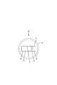
一対の電極部11は図1及び図2に示すように、中央に形成された圧着部12と、圧着部12の両側に設けられた凹み形状の逃がし部13と、各逃がし部13に隣接して設けられた扁平面状の電極接触部14と、を備える。
圧着部12は、図6に示すように、正面視弧状をなし、手前側と奥側に傾斜面が形成されている。逃がし部13は正面視弧状をなしており、圧着部12により圧着された筒状部25を側方に逃がす部分である。
逃がし部13の隣りに形成された扁平面状をなす部分は、図7に示すように他方の電極部11と接触する電極接触部14である。下側電極11Bの電極接触部14の上端面、および上側電極11Aの電極接触部14の下端面は、溶接の際に、相互に接触する。
次に、本実施形態の抵抗溶接用の電極10を用いて作製した端子付き電線20について説明する。端子付き電線20は、電線21の端末において露出した露出導体22を端子24に接続してなるものである。
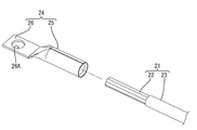
端子付き電線20を構成する電線21としては、特に限定されないが、例えば、銅製、銅合金製、アルミニウム製、またはアルミニウム合金製の金属素線をよりあわせた撚り線からなる導体22を絶縁被覆23で被覆してなる電線21などを用いることができる(図4を参照)。
端子24としては、電極10よりも抵抗値が高く融点が低い金属材料を用いることができる。
端子24は、図4に示すように、円筒状をなし電線21の露出導体22が接続される筒状部25と、他の端子と接続される端子接続部26と、からなる。板状をなす端子接続部26の略中央には他の端子が挿通され接続される円形の端子挿通孔26Aが貫通して形成されている。
端子付き電線20の作製方法について説明する。電線21の端末の絶縁被覆23を剥離除去し導体22を露出させておく。次に、電線21の端末において露出している露出導体22を、図4に示すように、端子24の筒状部25に挿入して図5に示す状態とする。
次に、露出導体22を挿入した端子24の筒状部25を抵抗溶接により筒状部25を圧着して、端子24と電線21とを接続する。具体的には、露出導体22を挿入した端子24の筒状部25を、下側電極10Bの圧着部12と上側電極10Aの圧着部12に対応させて配置し、図6および図7に示すように、一対の電極10A,10Bを近づく方向に移動させ、一対の電極部11間に電流を流して抵抗溶接を行う。上側電極10Aの圧着部12と、下側電極10Bの圧着部12とが筒状部25に当接すると、筒状部25を介して上側電極10Aから下側電極10Bに電流が流れる。
上側電極10Aの圧着部12と下側電極10Bの圧着部12をさらに近づけると、上下に配された一対の電極10A,10Bの圧着部12に挟まれ押圧された筒状部25は上下方向の寸法が小さくなるように圧着されつつ、押圧された筒状部25は逃がし部13側に逃がされる。さらに一対の電極10A,10Bを近づけて上側電極10Aの電極接触部14の下端面と下側電極10Bの電極接触部14の上端面とが接触すると、電流は、筒状部25(端子24)に流れなくなり電極接触部14の間(電極部11間)に流れる。その結果、筒状部25が所望の形状(図7に示す断面形状)に圧着された端子付き電線20が得られる。
次に、本実施形態の作用・効果について説明する。
本実施形態において、端末において露出した露出導体22を挿通させた端子24の筒状部25とを抵抗溶接により接続する際に用いる電極10は、端子24より抵抗値が低い材料からなるとともに、一対の電極部11が筒状部25と接触して圧着する圧着部12と、他方の電極部11と接触する電極接触部14と、を有する。
本実施形態において、端末において露出した露出導体22を挿通させた端子24の筒状部25とを抵抗溶接により接続する際に用いる電極10は、端子24より抵抗値が低い材料からなるとともに、一対の電極部11が筒状部25と接触して圧着する圧着部12と、他方の電極部11と接触する電極接触部14と、を有する。
したがって、本実施形態の抵抗溶接用の電極10を用いて抵抗溶接により端子24の筒状部25を圧縮すると、圧着部12が筒状部25と接触して筒状部25を圧着しつつ、一方の電極部11の電極接触部14が他方の電極部11の電極接触部14と接触する。ここで、電極10は端子24よりも抵抗値が低い材料から構成されているので、電極接触部14同士が接触して一対の電極部11が接触すると、電流は筒状部25(端子24)に流れなくなり電極接触部14の間(電極部11間)に流れる。その結果、本実施形態によれば、被溶接物(筒状部25)を所望の形状としたときに加熱を停止することができるから、被溶接物を所望の形状とすることのできる抵抗溶接用の電極10を提供することができる。
また、本実施形態によれば、電極部11は圧着部12により圧着された筒状部25を逃がす逃がし部13を有しているから、圧着部12により圧着された筒状部25が逃がし部13に逃げるので、筒状部25がつぶれすぎることがない。
<他の実施形態>
本発明は上記記述及び図面によって説明した実施形態に限定されるものではなく、例えば次のような実施形態も本発明の技術的範囲に含まれる。
(1)上記実施形態では、圧着部12により圧着された筒状部25を逃がす逃がし部13を備える電極10を示したが、逃がし部を備えないものであってもよい。
(2)上記実施形態では圧着部12の両側に逃がし部13を備える電極10を示したが、逃がし部は圧着部の片側に設けられていてもよい。
(3)上記実施形態では図7に示す形状の筒状部25が得られるような電極10を示したが、筒状部25の形状はこれに限定されない。楕円状や長方形状の筒状部が得られるように圧着部や逃がし部の形状を設定してもよい。
本発明は上記記述及び図面によって説明した実施形態に限定されるものではなく、例えば次のような実施形態も本発明の技術的範囲に含まれる。
(1)上記実施形態では、圧着部12により圧着された筒状部25を逃がす逃がし部13を備える電極10を示したが、逃がし部を備えないものであってもよい。
(2)上記実施形態では圧着部12の両側に逃がし部13を備える電極10を示したが、逃がし部は圧着部の片側に設けられていてもよい。
(3)上記実施形態では図7に示す形状の筒状部25が得られるような電極10を示したが、筒状部25の形状はこれに限定されない。楕円状や長方形状の筒状部が得られるように圧着部や逃がし部の形状を設定してもよい。
10:抵抗溶接用の電極
10A:上側電極
10B:下側電極
11:電極部
12:圧着部
13:逃がし部
14:電極接触部
20:端子付き電線
21:電線
22:導体(露出導体)
23:絶縁被覆
24:端子
25:筒状部
26:端子接続部
26A:端子挿通孔
10A:上側電極
10B:下側電極
11:電極部
12:圧着部
13:逃がし部
14:電極接触部
20:端子付き電線
21:電線
22:導体(露出導体)
23:絶縁被覆
24:端子
25:筒状部
26:端子接続部
26A:端子挿通孔
Claims (3)
- 導体を絶縁被覆で覆った電線の端末において露出した露出導体と、当該露出導体を挿通した筒状部を有する端子の当該筒状部と、を抵抗溶接により接続する電極であって、
前記端子より抵抗値が低い材料からなるとともに、前記露出導体を挿通した筒状部を挟む一対の電極部を有し、
前記電極部は前記筒状部と接触し当該筒状部を圧着する圧着部と、
他方の電極部と接触する電極接触部と、を有する抵抗溶接用の電極。 - 前記電極部は前記圧着部により圧着された前記筒状部を逃がす逃がし部を有する請求項1に記載の抵抗溶接用の電極。
- 導体を絶縁被覆で覆った電線の端末において露出した露出導体と、当該露出導体を挿通した筒状部を有する端子の当該筒状部とを、請求項1または請求項2に記載の抵抗溶接用の電極を用いて抵抗溶接して得られた端子付き電線。
Applications Claiming Priority (2)
| Application Number | Priority Date | Filing Date | Title |
|---|---|---|---|
| JP2015-141059 | 2015-07-15 | ||
| JP2015141059A JP6569345B2 (ja) | 2015-07-15 | 2015-07-15 | 抵抗溶接用の電極および端子付き電線 |
Publications (1)
| Publication Number | Publication Date |
|---|---|
| WO2017010296A1 true WO2017010296A1 (ja) | 2017-01-19 |
Family
ID=57757690
Family Applications (1)
| Application Number | Title | Priority Date | Filing Date |
|---|---|---|---|
| PCT/JP2016/069382 Ceased WO2017010296A1 (ja) | 2015-07-15 | 2016-06-30 | 抵抗溶接用の電極および端子付き電線 |
Country Status (2)
| Country | Link |
|---|---|
| JP (1) | JP6569345B2 (ja) |
| WO (1) | WO2017010296A1 (ja) |
Cited By (1)
| Publication number | Priority date | Publication date | Assignee | Title |
|---|---|---|---|---|
| US12201824B2 (en) | 2019-11-28 | 2025-01-21 | Heraeus Deutschland GmbH & Co. KG | Micro lead for directional stimulation |
Families Citing this family (1)
| Publication number | Priority date | Publication date | Assignee | Title |
|---|---|---|---|---|
| FR3086875B1 (fr) * | 2018-10-05 | 2021-04-30 | Tyco Electronics France Sas | Dispositif pour souder un conducteur electrique avec un dispositif de connexion |
Citations (4)
| Publication number | Priority date | Publication date | Assignee | Title |
|---|---|---|---|---|
| JP2006190662A (ja) * | 2004-12-10 | 2006-07-20 | Hitachi Cable Ltd | 配線材およびその製造方法、並びにその製造に用いる抵抗溶接機 |
| JP2014099385A (ja) * | 2012-11-16 | 2014-05-29 | Auto Network Gijutsu Kenkyusho:Kk | 端子付き電線およびその製造方法 |
| JP2014164930A (ja) * | 2013-02-23 | 2014-09-08 | Furukawa Electric Co Ltd:The | 電線付き端子及びその製造方法 |
| JP2015006688A (ja) * | 2013-06-25 | 2015-01-15 | 日本タングステン株式会社 | 抵抗溶接用電極 |
Family Cites Families (1)
| Publication number | Priority date | Publication date | Assignee | Title |
|---|---|---|---|---|
| JP2012048833A (ja) * | 2010-08-24 | 2012-03-08 | Auto Network Gijutsu Kenkyusho:Kk | 端子圧着方法および端子圧着装置 |
-
2015
- 2015-07-15 JP JP2015141059A patent/JP6569345B2/ja active Active
-
2016
- 2016-06-30 WO PCT/JP2016/069382 patent/WO2017010296A1/ja not_active Ceased
Patent Citations (4)
| Publication number | Priority date | Publication date | Assignee | Title |
|---|---|---|---|---|
| JP2006190662A (ja) * | 2004-12-10 | 2006-07-20 | Hitachi Cable Ltd | 配線材およびその製造方法、並びにその製造に用いる抵抗溶接機 |
| JP2014099385A (ja) * | 2012-11-16 | 2014-05-29 | Auto Network Gijutsu Kenkyusho:Kk | 端子付き電線およびその製造方法 |
| JP2014164930A (ja) * | 2013-02-23 | 2014-09-08 | Furukawa Electric Co Ltd:The | 電線付き端子及びその製造方法 |
| JP2015006688A (ja) * | 2013-06-25 | 2015-01-15 | 日本タングステン株式会社 | 抵抗溶接用電極 |
Cited By (1)
| Publication number | Priority date | Publication date | Assignee | Title |
|---|---|---|---|---|
| US12201824B2 (en) | 2019-11-28 | 2025-01-21 | Heraeus Deutschland GmbH & Co. KG | Micro lead for directional stimulation |
Also Published As
| Publication number | Publication date |
|---|---|
| JP6569345B2 (ja) | 2019-09-04 |
| JP2017022065A (ja) | 2017-01-26 |
Similar Documents
| Publication | Publication Date | Title |
|---|---|---|
| JP5741502B2 (ja) | 端子付き電線およびその製造方法 | |
| JP5654242B2 (ja) | 電線の端末処理方法 | |
| CN107005014B (zh) | 带端子电线及带端子电线的制造方法 | |
| JP6574736B2 (ja) | 端子付き電線の製造方法 | |
| JP6574795B2 (ja) | 端子付き電線の製造方法 | |
| US10777911B2 (en) | Electric cable connecting terminal and method for connecting together electric cable connecting terminal and electric cable | |
| WO2016017013A1 (ja) | 端子と電線の接合方法および電線接続用の端子 | |
| JP2015041509A (ja) | 導電路及び電線 | |
| JP4961444B2 (ja) | Al線半田付け方法及び端子 | |
| JP5989511B2 (ja) | 電線と端子の接続方法 | |
| US20170162953A1 (en) | Crimp terminal, connecting structure, manufacturing method of the crimp terminal, and laser welding method | |
| CN106537691B (zh) | 端子连接结构及其制造方法 | |
| JP6569345B2 (ja) | 抵抗溶接用の電極および端子付き電線 | |
| JP6074285B2 (ja) | 端子と電線の接合方法および電線接続用の端子 | |
| JP2013165011A (ja) | 端子付き電線およびその製造方法 | |
| JP2010176880A (ja) | 端子金具付き電線 | |
| CN107538094B (zh) | 一种多股导线与微细丝的精密电阻钎焊方法 | |
| CN107004962B (zh) | 导线和制备导线以接收接触元件的方法 | |
| WO2013183160A1 (ja) | 端子金具付き電線及び端子金具付き電線の製造方法 | |
| WO2018092597A1 (ja) | 圧着端子および端子付き電線 | |
| CN208111701U (zh) | 端子 | |
| JP2016046176A (ja) | 溶接継手、該溶接継手を備える端子、溶接継手の製造方法、および端子の製造方法 | |
| JP2017152094A (ja) | 端子部材 | |
| JP2025164441A (ja) | 端子付き電線、及び、端子付き電線の製造方法 | |
| JP2019032927A (ja) | バスバー、電線付きバスバー、および電線付きバスバーの製造方法 |
Legal Events
| Date | Code | Title | Description |
|---|---|---|---|
| 121 | Ep: the epo has been informed by wipo that ep was designated in this application |
Ref document number: 16824276 Country of ref document: EP Kind code of ref document: A1 |
|
| NENP | Non-entry into the national phase |
Ref country code: DE |
|
| 122 | Ep: pct application non-entry in european phase |
Ref document number: 16824276 Country of ref document: EP Kind code of ref document: A1 |