WO2017009911A1 - 超音波通信装置、超音波通信方法、並びにそれを用いた情報処理装置 - Google Patents
超音波通信装置、超音波通信方法、並びにそれを用いた情報処理装置 Download PDFInfo
- Publication number
- WO2017009911A1 WO2017009911A1 PCT/JP2015/069964 JP2015069964W WO2017009911A1 WO 2017009911 A1 WO2017009911 A1 WO 2017009911A1 JP 2015069964 W JP2015069964 W JP 2015069964W WO 2017009911 A1 WO2017009911 A1 WO 2017009911A1
- Authority
- WO
- WIPO (PCT)
- Prior art keywords
- ultrasonic
- information
- waves
- unit
- transmission
- Prior art date
- Legal status (The legal status is an assumption and is not a legal conclusion. Google has not performed a legal analysis and makes no representation as to the accuracy of the status listed.)
- Ceased
Links
Images






Classifications
-
- H—ELECTRICITY
- H04—ELECTRIC COMMUNICATION TECHNIQUE
- H04B—TRANSMISSION
- H04B1/00—Details of transmission systems, not covered by a single one of groups H04B3/00 - H04B13/00; Details of transmission systems not characterised by the medium used for transmission
- H04B1/38—Transceivers, i.e. devices in which transmitter and receiver form a structural unit and in which at least one part is used for functions of transmitting and receiving
-
- H—ELECTRICITY
- H04—ELECTRIC COMMUNICATION TECHNIQUE
- H04B—TRANSMISSION
- H04B13/00—Transmission systems characterised by the medium used for transmission, not provided for in groups H04B3/00 - H04B11/00
- H04B13/02—Transmission systems in which the medium consists of the earth or a large mass of water thereon, e.g. earth telegraphy
-
- H—ELECTRICITY
- H04—ELECTRIC COMMUNICATION TECHNIQUE
- H04B—TRANSMISSION
- H04B7/00—Radio transmission systems, i.e. using radiation field
- H04B7/02—Diversity systems; Multi-antenna system, i.e. transmission or reception using multiple antennas
- H04B7/04—Diversity systems; Multi-antenna system, i.e. transmission or reception using multiple antennas using two or more spaced independent antennas
- H04B7/06—Diversity systems; Multi-antenna system, i.e. transmission or reception using multiple antennas using two or more spaced independent antennas at the transmitting station
Definitions
- the present invention relates to an ultrasonic communication apparatus, an ultrasonic communication method, and an information processing apparatus using the same.
- Patent Document 1 states that “the configuration of the present invention includes an ultrasonic transmission / reception unit that transmits an ultrasonic wave between the ultrasonic transmission / reception unit and an ultrasonic conversion unit and an ultrasonic transmission / reception unit on the telephone body.
- the ultrasonic conversion unit is provided in the wireless transmission / reception unit so that communication is possible.
- the telephone can be used without holding the telephone body, and the transmission quality is good without affecting the radio. " Are listed.
- Japanese Patent Laid-Open No. 2004-228688 describes that “the telephone system detects at least one of the position and direction of the partner electronic device and controls the directivity of the speaker unit to at least one of the detected position and direction. Therefore, it is possible to provide a sound wave having a sufficient volume only for a specific user without generating noise in the surroundings. "
- Patent Document 1 and Patent Document 2 have been proposed.
- communication with good directivity and transmission quality can be performed using an ultrasonic element speaker, but there is a problem that the band is limited.
- the technique disclosed in Patent Document 2 discloses that the directivity is controlled by superimposing sound pressure on a specific position of an ultrasonic speaker unit so that a necessary sound volume is obtained.
- An object of the present invention is to provide an ultrasonic communication apparatus and an ultrasonic communication method that cannot decode digital data even when the digital data is decoded, and an information processing apparatus using the ultrasonic communication apparatus.
- the present invention adopts, for example, the configurations described in the claims.
- the present application includes a plurality of components that solve the above-described problems.
- an ultrasonic communication apparatus that transmits information by ultrasonic waves, and that transmits a plurality of ultrasonic waves to a transmission unit.
- a sound wave element a modulation unit that modulates a carrier wave with transmission information and outputs a modulated wave, a time division unit that time-divides the modulated wave into a plurality of times, a jamming signal generation unit, and a jamming signal divided in an antiphase relationship
- An adder / subtractor for adding / subtracting the modulated wave, and distance correction information for correcting the position information from the plurality of ultrasonic elements to the microphone of the receiving device, and correcting the phase delay amount and the amplitude of each of the divided modulated waves
- a distance correction unit and a control unit that controls the entire transmission unit are included, and a plurality of ultrasonic elements are driven by each of the corrected divided modulated waves to emit ultrasonic waves.
- FIG. 1 is a configuration diagram illustrating a basic configuration of an ultrasonic communication device according to Embodiment 1.
- FIG. 1 is a configuration diagram illustrating a transmission / reception integrated configuration of an ultrasonic communication device in Embodiment 1.
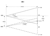
- FIG. It is a figure explaining the positional relationship of PSP and a microphone in Example 1.
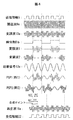
- FIG. 3 is an explanatory diagram illustrating signals of the ultrasonic communication device according to the first embodiment.
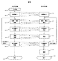
- FIG. 5 is a process flow diagram illustrating an operation example of the ultrasonic communication apparatus according to the first embodiment.
- FIG. 6 is a configuration diagram illustrating a configuration of an ultrasonic communication device according to a second embodiment.
- FIG. 10 is a configuration diagram illustrating a configuration of an ultrasonic communication device according to a third embodiment.
- FIG. 10 is a configuration diagram illustrating a configuration of a projector device to which an ultrasonic communication device according to a third embodiment is applied according to a fifth embodiment. It is a block diagram which shows the structure of ATM to which the ultrasonic communication apparatus of Example 3 in Example 6 is applied. It is a block diagram which shows the structure of the spectacles type terminal device to which the ultrasonic communication apparatus of Example 3 in Example 7 is applied. It is a block diagram which shows the structure of the wristwatch type
- FIG. 1 is a configuration diagram showing a basic configuration of an ultrasonic communication apparatus according to the present embodiment.
- FIG. 2 is a configuration diagram illustrating a transmission / reception integrated configuration of the ultrasonic communication apparatus according to the present embodiment.
- the transmitting device 1 is divided into the transmitting unit 3 and the receiving device 2 is divided into the receiving unit 4, but as shown in FIG.
- the transmission / reception integrated structure having 3 and the receiving unit 4 will be described.
- the configuration may be selected according to the application.
- the ultrasonic communication apparatus is a communication apparatus using ultrasonic waves
- the transmission unit 3 includes a control unit 8, an oscillation unit 9, a modulation unit 10, and time division.
- Unit 11 interference signal generation unit 12, addition unit 13, subtraction unit 14, distance correction units 15 and 16, and PSPs (parametric speakers) 1 and 2 including ultrasonic elements as vibration emission units.
- the reception unit 4 includes a microphone 19, a demodulation unit 20, and a propagation determination unit 21.
- the ultrasonic propagation medium is 1 atm of dry air at a temperature of 14 ° C.
- the transmission side device 1 and the reception side device 2 have a line-of-sight of 150 mm
- the vibration radiation parts PSP1 and 2 have a vibration frequency of 40 kHz.
- the transmission information 5 is digital data with a transfer rate of 20 kbps (bit per second).
- the ultrasonic element will be described as instantaneously responding to the drive waveform.
- the transfer rate of digital data may be determined in consideration of the response delay of the ultrasonic element.
- the propagation information ds1,2 when the ultrasonic waves WV1 (17), WV2 (18) emitted from the PSPs 1, 2 shown in FIG. 1 reach the microphone 19 corresponds to the transmission delay to the microphone, and the above conditions This is information on a propagation distance and a propagation time that are further determined. Media information may be used.
- the ultrasonic oscillating element, the frequency control method, and the position specifying method using ultrasonic waves may be the processing disclosed in Patent Document 2, and the description thereof will be limited to the necessary portions, and the details will be omitted.
- position information 6 is propagation information ds1 and 2 determined under the above conditions.
- the modulation information 7 indicates the ultrasonic oscillation frequency and the division method.
- the reception information 22 is digital data obtained by demodulation.
- the correction information 23 indicates the correction amount of the propagation information ds1 and 2 obtained from the arrival information of the ultrasonic waves WV1 and WV2 that have reached the microphone 19.
- the control unit 8 uses the position information 6 and the modulation information 7 to generate ultrasonic oscillation frequency information 8 a of 40 kHz, time division information 8 b that is switched every 7 cycles of ultrasonic waves, and 1 / of the ultrasonic frequency.
- the distance correction information dc1 and 2 determined from the difference between the interference wave information 8c of 5 and 8 kHz and the propagation information ds1 and 2 are generated.
- the oscillating unit 9 amplitude modulates the carrier wave 9a of a 40 kHz SIN wave to 100% -50% with the digital data (1, 0) of the transmission information 5 by the modulating unit 10 to generate a modulated wave 10a.
- the modulation may be FM modulation.
- the time division unit 11 divides the modulated wave 10a into two modulated waves 1 and 2 according to the time division information 8b.
- the time division information 8b may be a switching signal lower than the data rate of transmission information, and is inverted every seven carrier waves in this embodiment. Further, the cycle may be fixed or the cycle may be changed.
- the interference signal generation unit 12 generates a SIN wave interference signal 12a at 8 kHz according to the interference wave information 8c, and the addition unit 13 adds and superimposes the modulation wave 1 and the subtraction unit 14 subtracts and superimposes the modulation wave 2.
- the signals 12a are in a reverse phase relationship. It operates as a so-called active noise cancellation (ANC) function.
- ANC active noise cancellation
- the distance correction information dc1 and dc2 are time information.
- propagation information ds1> ds2, dc1
- the distance correction unit 15 corrects the modulated wave 1 with the sound pressure attenuation amount of the time difference of dc1 and the time difference during propagation.
- the distance correction unit 16 corrects the modulated wave 2 based on dc2.
- the vibration radiation parts PSP1 and 2 are driven by the modulated waves 1 and 2, respectively, and the ultrasonic waves WV1 and 2 are emitted.
- the ultrasonic waves WV1 and 2 propagated by the microphone 19 using the propagation information ds1 and 2 and superimposed on each other are collected to obtain a reproduced wave 19a.
- the above-described distance correction information dc1 and dc2 are appropriate, the signal waveform corresponding to the state in which the disturbing signal 12a is canceled in the reproduced wave 19a and the phases of the ultrasonic waves WV1 and 2 are aligned, that is, the modulation wave 10a on the transmission side. It becomes.
- the demodulating unit 20 reversely calculates the reproduced 40 kHz carrier wave component to obtain digital data as reception information 22.
- the propagation determination unit 21 generates correction information 23 according to the remaining amount of the interference signal 12a component present in the reproduced wave 19a. If the distance correction information dc1 and dc2 are appropriate, the remaining component is 0, the correction information 23 is 0, and if the distance correction information dc1 and 2 are inappropriate, the remaining component is generated as a wavy waveform and propagates from its phase and amplitude. The correction amount of the information ds1, 2 is determined. The correction information 23 is transmitted to the transmission side device 1 by the configuration of FIG. 2 and corrects the distance correction information dc1 and dc2. By repeating the above, the distance correction information dc1, 2 is optimized.
- the microphone 19 may use the resonance of an ultrasonic element, but may be a high-sensitivity broadband microphone that can capture from the audible band to the ultrasonic band.
- the transmission side device 1 or the reception side device 2 moves within the range where the WVs 1 and 2 reach the microphone 19 at the same time, the residual component is generated as a wavy waveform.
- the correction information dc1 and 2 are optimized.
- FIG. 3 is a diagram for explaining the positional relationship between the PSP and the microphone in this embodiment.
- the microphone 19 when the microphone 19 is located at a distance of 150 mm that opposes the intermediate position between the PSP 1 and PSP 2 with respect to the vibration radiation parts PSP 1 and 2 arranged with a gap of 50 mm, the distance between the PSP 2 and the microphone is 152.07 mm. Becomes 17,89 ⁇ .
- the distances between the microphone and PSP1 and PSP2 are the same, the distances at which the ultrasonic waves WV1 (17) and WV2 (18) emitted from PSP1 and PSP2 reach the microphone 19 are the same and the phases match. To do.
- the ultrasonic waves from the PSP1 and PSP2 are aligned at the position of the microphone 19 by delaying the ultrasonic waves of the shorter distance. Then, control is performed according to the above.
- FIG. 4 shows each signal of the ultrasonic communication apparatus in the present embodiment.
- a carrier wave 9a is amplitude-modulated with digital data (1, 0) of transmission information 5 to generate a modulated wave 10a.
- the modulated wave 10a is divided into two modulated waves 1 and 2 according to the time division information 8b.
- the interference signals 12a are added and subtracted, and the ultrasonic waves WV1 and WV2 are emitted from the vibration radiation parts PSP1 and PSP2 and collected by the microphone 19 to obtain a reproduced wave 19a.
- the reception information 22 is obtained by demodulating from the reproduction wave 19a.
- the distance correction information dc1 and dc2 are determined in consideration of the propagation information ds1 and 2 so that the phases match at the synthesis point of the reproduced wave 19a.
- FIG. 5 is a processing flow showing an operation example of the ultrasonic communication apparatus according to the present embodiment.
- the communication processing procedure between the transmission side device 1 and the reception side device 2 follows a general start-up type communication establishment procedure and will not be described in detail.
- the processing includes an environment determination 102, transmission condition determination 103, modulation transmission 104, reception state confirmation 105, and correction information 23.
- the receiving-side apparatus 2 includes processing for communication establishment 110, position / environment determination 111, transmission condition determination 113, reception 113, reception state confirmation 114, correction information 23, and demodulation 115.
- the transmission / reception conditions such as interference wave superposition and transmission rate are relaxed, reliable transmission / reception is established, and both devices are recognized.
- the vibration radiation parts PSP1 and PSP2 may be used.
- Position / environment determination 102 and 111 determine the above-described positional relationship and environmental conditions such as atmospheric pressure, temperature, humidity, and wind speed.
- transmission condition determinations 103 and 112 transmission conditions are determined based on the above-described transfer rate, carrier wave frequency, and distance correction information dc1 and dc2. Then, transmission / reception of information is carried out by modulation transmission 104 and reception 113.
- the reception status confirmations 105 and 114 the received signal quality is evaluated as the correction information 23, such as the presence / absence of interference waves in the received signal and the continuity of the waveform.
- the correction information 23 such as the presence / absence of interference waves in the received signal and the continuity of the waveform.
- the transmission information is reproduced by demodulation 115.
- the interference signal 12a may be a frequency that can be superimposed on the modulated waves 1 and 2, and the transmission information 5 cannot be demodulated with only one of the modulated waves 1 and 2.
- the influence of the interference wave and the phase of the combined modulation wave are not aligned and cannot be reproduced. That is, since the interference signal is canceled only at the position of the microphone 19 and the phases of the combined modulated waves are aligned, it is possible to ensure confidentiality and confidentiality when transmitting the transmission information 5.
- the digital data is an audio signal
- the frequency band can be controlled to avoid annoying band.
- radio waves and optical communications cannot be used / accessed or underwater, Transmission can be performed in consideration of wall reflections even in a strong magnetic field space where radio waves are disturbed, a space where light emission is hated, and a space where line-of-sight communication is not possible.
- marine sports can be used underwater, and sonar can be applied to submarines.
- the interference signal 12a can be removed if there is a distance difference of 42.5 mm in wavelength, but cannot be reproduced because the phases of the modulated waves 1 and 2 are not aligned.
- the receiving-side apparatus 2 may send out an ultrasonic wave to which GPS, a time stamp, and a phase difference are added.
- the transmission side apparatus 1 may receive this, demodulate, and specify a position.
- Digital data may be modulated with any of ultrasonic frequency, phase and amplitude.
- the ultrasonic wave is divided in units of one wavelength, the output phase and amplitude are adjusted according to the distance to the destination, and output from each ultrasonic element.
- a continuous wavelength is formed by multiplexing and superimposing at the pointing destination.
- the sound pressure of the ultrasonic wave is at an energy level that vibrates the receiving member of the microphone 19, and control is performed so that the signals are aligned, not the sound pressure.
- the digital data may be clustered and divided into a plurality of segments, and the above may be performed in time series on a segment basis. Further, a plurality of the above may be performed simultaneously in a segment unit.
- division, arrangement, correction method, encryption, and the like of digital data may be any conventional digital communication method, and may be determined from a desired transmission rate and error tolerance.
- the partner position may be specified by both the transmitting side device 1 and the receiving side device 2.
- a laser distance meter may be used in combination.
- a one-dimensional array or a two-dimensional array may be used as a method for arranging the ultrasonic elements.
- the present invention is not limited to this, and the number of ultrasonic waves and the number of divisions may be two or more.
- the configuration according to the present application can improve the transfer rate and confidentiality of digital data.
- the transmission directivity of ultrasonic waves may be widened to enlarge the transmission target area.
- directivity may be managed using an ultrasonic lens.
- reception is performed on the extension axis of the transmission side apparatus 1 and the reception side apparatus 2, and when ds1 ⁇ ds2, the reception is performed in the vicinity of the extension axis of the transmission side apparatus 1 and the reception side apparatus 2.
- all of them are within the line-of-sight range, and confidentiality may be ensured by paying attention to the operator.
- the upper limit of the transmission rate can be improved by increasing the frequency of the carrier wave or by increasing the frequency, but it is equivalent to several tens of kHz, and is applicable to voice, character code, ID transmission / reception and the like.
- a parametric speaker including a plurality of ultrasonic elements is configured to control and drive frequency, phase, and amplitude modulation and time division processing, and each ultrasonic wave is divided, for example, in units of periods. Then, the phase and amplitude are adjusted and output according to the distance from each ultrasonic element to the reception position. In the reception position, the interference waves cancel each other, and the original continuous wave is formed.
- an ultrasonic communication apparatus that transmits information using ultrasonic waves
- the transmitter includes a plurality of ultrasonic elements that emit ultrasonic waves, a modulation unit that modulates a carrier wave with transmission information and outputs a modulated wave, and a modulation unit.
- a time division unit for time-dividing a wave into a plurality of times, a jamming signal generation unit, an addition / subtraction unit for adding / subtracting the modulation signal obtained by splitting the jamming signal so as to have an antiphase relationship, and a microphone of the receiving device from a plurality of ultrasonic elements
- Distance correction information for correcting position information up to and including a distance correction unit that corrects the phase delay amount and amplitude of each of the divided modulated waves, and a control unit that controls the entire transmission unit, and is corrected.
- Each of the divided modulated waves is configured to drive a plurality of ultrasonic elements to emit ultrasonic waves.
- an ultrasonic communication method for transmitting information by ultrasonic waves, having a plurality of ultrasonic elements that emit ultrasonic waves, modulating a carrier wave with transmission information, time-dividing the modulated modulated wave into a plurality of times, Each phase of the modulated wave generated by generating a jamming signal, adding / subtracting the jamming signal to the modulated wave divided so as to have an antiphase relationship, and dividing according to the positional information from the plurality of ultrasonic elements to the microphone of the receiving device. Correcting the delay amount and amplitude, driving the plurality of ultrasonic elements with each of the corrected divided modulated waves, emitting ultrasonic waves, and collecting the reproduced waves that collected the ultrasonic waves from the plurality of ultrasonic elements. When the phases of the ultrasonic waves are aligned, the interference signals are mutually canceled.
- FIG. 6 is a configuration diagram showing the configuration of the ultrasonic communication apparatus in the present embodiment.
- the ultrasonic communication apparatus according to the present embodiment includes a transmission-side apparatus 200 and a reception-side apparatus 300, and a configuration different from that in FIG. 1 is that the transmission-side apparatus 200 includes a distance measuring unit 24.
- the receiving side apparatus 300 describes only the receiving unit 4, and the transmitting unit 3 is omitted.
- the distance measuring unit 24 in this embodiment has a function of specifying the distance and direction to the microphone 19 of the receiving side device 2 as the position information 6.
- the distance measuring method may be an optical distance measuring device using a TOF (Time Of Flight) method that measures the return time of a light beam using a general LED light or laser light and an optical sensor. Of course, ultrasonic waves may be used. That is, as shown in FIG. 6, the position information 6 detected by the distance measuring unit 24 is input as the position information 6 to the control unit 8.
- TOF Time Of Flight
- the reception side device 2 transmits the correction amount of the propagation information ds1 and 2 to the transmission side device 1, but in this embodiment, the microphone of the reception side device 300 is transmitted on the transmission side device 200 side. Since the distance and direction up to 19 can be specified, the transmission unit of the receiving-side apparatus 300 can be simplified, and the apparatus cost can be reduced. That is, the apparatus cost of the ultrasonic communication apparatus having the transmission / reception integrated configuration including the transmission unit 3 and the reception unit 4 can be reduced. For example, it can be used as a remote control to send only to the target device.
- the range of use is limited to a distance that is not affected by light attenuation.
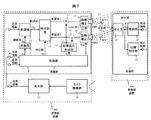
- FIG. 7 is a configuration diagram showing the configuration of the ultrasonic communication apparatus according to the present embodiment.
- the ultrasonic communication apparatus according to the present embodiment includes a transmission-side apparatus 400 and a reception-side apparatus 500, and a configuration different from that in FIG. 1 is that the transmission-side apparatus 400 includes a camera imaging unit 31 and a display unit 30.
- the other configurations are the same and are given the same reference numerals.
- the receiving-side device 500 describes only the receiving unit 4, and the transmitting unit 3 is omitted.
- the display unit 30 displays the captured image of the camera imaging unit 31 and the sighting device as the target position to be transmitted, and the microphone 19 of the receiving-side device 500 enters the captured image and matches the sighting device.
- the transmission side device 400 is moved.
- a start button is prepared, and the transmission side apparatus 400 is instructed to start communication at the coincident timing. That is, the camera imaging unit and the display unit have the function of an optical distance measuring device.
- Example 1 the correction amount of the propagation information ds1 and 2 was transmitted from the reception side device 2 to the transmission side device 1, but in this embodiment, the microphone of the reception side device 500 is transmitted on the transmission side device 400 side. Since the direction up to 19 can be specified, the transmission unit of the receiving-side apparatus 500 can be simplified, and the apparatus cost can be reduced. That is, the apparatus cost of the ultrasonic communication apparatus having the transmission / reception integrated configuration including the transmission unit 3 and the reception unit 4 can be reduced. For example, it can be used as a remote control to send only to the target device.
- this embodiment can communicate at a distance within the line-of-sight range both in the air and underwater.
- the distance measuring method may be other than that as long as the target position can be specified.
- FIG. 8 is a diagram illustrating a configuration of a mobile terminal device to which the ultrasonic communication device according to the present embodiment is applied.
- the mobile terminal device 40 is a terminal device that is supported and used by an operator with one hand or both hands, and includes a display unit 30 that receives an image display and an operation input using, for example, an operator's fingers.
- the portable terminal device 40 in this embodiment is used as a transmission side, and information is transmitted to the reception side device 500.
- An aiming image 43 for specifying a transmission position and a camera image 42 by the camera 31 are displayed on the display unit 30.
- the operator adjusts the position of the supported hand, makes the camera image 42 displaying the marker of the microphone 19 of the receiving-side device 500 substantially coincide with the aiming image 43, and taps the aiming image 43 with the fingers.
- the tap operation with a finger may be a button operation, voice input, gesture operation, or the like, and any means may be used as long as it conveys the intention of input.
- the transmission unit as a communication device can be simplified. , Device cost can be reduced.
- a portable terminal device it may be applied to a tablet terminal, a wearable device, etc. to realize secret communication without contact. Further, as remote operation, keyboard operation, cursor movement, unlocking, screen operation, etc., automatic door opening / closing, touch SW device, operation switch, etc. may be used.
- FIG. 9 is a diagram illustrating a configuration of the PJ 50 to which the ultrasonic communication apparatus according to the present embodiment is applied. As shown in FIG. 9, the present embodiment is configured to transmit information using the PJ 50 in the present embodiment as a receiving-side device and the above-described portable terminal device 40 as a transmitting-side device.
- communication is transmitted to the PJ 50 according to the configuration and procedure described in the fourth embodiment.
- communication transmission contents personal authentication is performed by the portable terminal device 40, and display conditions such as selection of a file displayed on the PJ 50 and page turning are transmitted.
- the applicant sends an action (voice or smartphone operation) to the PJ 50, identifies the individual through communication transmission, sets priority, and displays it.
- the image transmission may be another network path.
- the display state is communicated from the PJ 50 to the mobile terminal device 40.
- the operator can remotely control the PJ50 while specifying the individual with confidentiality.
- the camera 31 and the display unit 30 that the mobile terminal device 40 originally has can be used for the function of specifying the distance and direction to the microphone 19 of the PJ 50, the transmission unit as a communication device can be simplified, and the device cost can be reduced. Can be reduced.
- the present invention is not limited to the portable terminal device 40, and may be an embodiment described later, and the same configuration and effect can be obtained.
- FIG. 10 is a diagram illustrating a configuration of the ATM 60 to which the ultrasonic communication apparatus according to the present embodiment is applied. As shown in FIG. 10, the present embodiment is configured to transmit information using the ATM 60 in the present embodiment as a receiving device and the mobile terminal device 40 described above as a transmitting device.
- the ATM 60 includes a card port 62 for inserting a cash card, a passbook port 63 for inserting a passbook, a cash port 64 for taking in and out cash, an operation screen display unit 61 of the ATM 60, and the like.
- communication is transmitted to the ATM 60 by the configuration and procedure described in the fourth embodiment.
- personal authentication is performed by the mobile terminal device 40, and the personal identification number input or previously inputted is transmitted by communication.
- the ATM 60 communicates the authentication status, account information, and handling details such as transfer processing to the mobile terminal device 40 by communication.
- cash collection and bankbook entry are carried out at ATM60.
- the ultrasonic communication device By incorporating the ultrasonic communication device into the ATM 60 in this manner, the operator does not need to operate the ATM 60 directly, and since it is operated on the mobile terminal device 40 side, the PIN number can be input and the deposit and savings can be performed while maintaining confidentiality. Or transfer processing is possible. Further, since the camera 31 and the display unit 30 that the mobile terminal device 40 originally has can be used for the function of specifying the distance and direction to the microphone 19 of the ATM 60, the transmission unit as a communication device can be simplified, and the device cost can be reduced. Can be reduced.
- this configuration is not limited to the ATM 60, and the same configuration and effects can be obtained even for vending machines, ticket vending machines, POS, and the like. Further, the present invention is not limited to the portable terminal device 40, and may be an embodiment described later, and the same configuration and effect can be obtained.
- FIG. 11 is a diagram illustrating a configuration of a glasses-type terminal device 70 to which the ultrasonic communication device according to the present embodiment is applied.
- the glasses-type terminal device 70 is, for example, glasses-type, and includes a display operation unit 71 that receives image display and operation input. Further, the image displayed on the display operation unit 71 is also displayed on the display unit 72 which is a virtual image area in space. A state of the visual field of the operator wearing the glasses-type terminal device 70 is indicated by 74.
- the glasses-type terminal device 70 in this embodiment is used as a transmission side, and information is transmitted to the reception side device 500.
- An aiming image 73 for specifying a transmission position and a camera image 75 by the camera 31 are displayed on the display unit 72 which is a virtual image area.
- the camera image 75 may not be displayed.
- the operator adjusts the position of the head to make the camera image 75 or the camera image 75 displaying the marker of the microphone 19 of the receiving-side device 500 visible in real space substantially coincide with the aiming image 73.
- tapping 71 communication is started and information is transmitted in the same manner as in the previous embodiment.
- the tap operation may be a button operation, voice input, blinking, gesture operation, or the like, and any means may be used as long as it conveys the intention of input.
- the reception target is a target that performs a SW operation with the force of sound pressure
- the sound pressure may be presented and the SW operation may be operated, or remote control using a line of sight may be performed by blinking or the like.
- FIG. 12 is a diagram showing a configuration of a wristwatch type terminal device 80 to which the ultrasonic communication device in the present embodiment is applied.
- the wristwatch-type terminal device 80 is a terminal device that is used by being worn on the operator's arm 84, and has a display operation unit 85 that accepts image display and, for example, an operation input by the operator's finger 86. .
- the wristwatch type terminal device 80 in the present embodiment is used as a transmission side, and information is transmitted to the reception side device 500.
- An aiming image 83 for specifying a transmission position and a camera image 82 by the camera 31 are displayed on the display unit 30.
- the operator adjusts the position of the arm 84 so that the camera image 82 on which the camera image 82 displays the marker of the microphone 19 of the receiving-side apparatus 500 substantially coincides with the aiming image 83.
- the tap operation with a finger may be a button operation, voice input, gesture operation, or the like, and any means may be used as long as it conveys the intention of input.
- the transmission unit as a communication device is simplified. This can reduce the device cost.
- the devices according to the first to eighth embodiments are examples, and any device can be used as long as operation support is realized by communication according to the purpose by incorporating the transmission unit 3 and the reception unit 4. There may be.
- the present invention can be applied to a device that can be conveniently provided by an interface with a person, such as a bicycle, an audi, a unicycle, a human assist robot, a robot, a medical device, or a medical care bed.
- the ultrasonic sound pressure may be presented as the palm or the entire back of the hand.
- an ultrasonic sound pressure can be transmitted to the palm or back of the hand only at the presentation position without an interfering wave, and a sound pressure that does not make sense due to the interfering wave is presented in other areas.
- This makes it possible to transmit information while maintaining confidentiality in a non-contact manner.
- it may be any of the whole body as long as the receiver can recognize the change of the sound pressure.
- the ultrasonic communication device in Examples 1 to 8 may be incorporated into various buttons such as a flush button for toilets, an automatic door opening / closing button, and an elevator floor instruction button, and button operation may be realized through communication.
- Non-contact button operation can ensure hygiene and improve operability.
- the present invention can also be applied to game machines (pachinko, pachislot, games, etc.).
- this invention is not limited to the above-mentioned Example, Various modifications are included.
- the above-described embodiments have been described in detail for easy understanding of the present invention, and are not necessarily limited to those having all the configurations described.
- each of the above-described configurations, functions, processing units, and the like may be realized by hardware by designing a part or all of them with, for example, an integrated circuit.
- Each of the above-described configurations, functions, and the like may be realized by software by interpreting and executing a program that realizes each function by the processor.
- Information such as programs, tables, and files that realize each function can be stored in a storage medium, storage, or the like.
- the control lines and information lines indicate what is considered necessary for the explanation, and not all the control lines and information lines on the product are necessarily shown. Actually, it may be considered that almost all the components are connected to each other.
Landscapes
- Engineering & Computer Science (AREA)
- Computer Networks & Wireless Communication (AREA)
- Signal Processing (AREA)
- Measurement Of Velocity Or Position Using Acoustic Or Ultrasonic Waves (AREA)
Abstract
電波の影響が無く、特定の相手とのみ指向性と、特定の相手以外の位置で傍受してもデジタルデータを復号できない秘匿性と、周囲への騒音を抑え且つ不要電界を発生させない通信を実現することを目的とする。 そのために、超音波で情報を伝達する超音波通信装置であって、送信部に、超音波を放出する複数の超音波素子と、搬送波を送信情報で変調し変調波を出力する変調部と、変調波を複数に時分割する時分割部と、妨害信号の生成部と、妨害信号を逆相関係となるよう分割した変調波に加減算する加減算部と、複数の超音波素子から受信側装置のマイクまでの位置情報を補正する距離補正情報を得て、分割した変調波のそれぞれの位相遅延量と振幅を補正する距離補正部と、送信部全体を制御する制御部と、を有し、補正された分割した変調波のそれぞれで複数の超音波素子を駆動し超音波を放出する構成とする。
Description
本発明は、超音波通信装置及び超音波通信方法、並びにそれを用いた情報処理装置に関する。
本技術分野の背景技術として、特開平8-167924号公報(特許文献1)、及び、特開2012-134588号公報(特許文献2)がある。特許文献1には、「本発明の構成は、電話機本体に超音波変換部と超音波送受音部を設けるとともに、超音波送受音部との間で超音波を伝送する超音波送受音部と超音波変換部をワイヤレス送受話部に設けて通信可能に構成した。発明の構成によれば、電話機本体を保持することなく電話機が使用可能であり、無線に影響なく伝送品質が良い。」と記載されている。
特許文献2には、「通話システムは、電子機器が相手の電子機器の位置と方向との少なくとも一方を検出し、検出された位置と方向との少なくとも一方にスピーカユニットの指向性を制御する。このため、周囲に騒音を発生することなく、特定のユーザのみに充分な音量の音波を提供することができる。」と記載されている。
デジタルデータの通信において、電波の影響が無く、特定の相手とのみ指向性と伝送品質の良い通信ができ、且つ、特定の相手以外の位置で傍受してもデジタルデータを復号できない秘匿性を有する通信が望まれている。また、周囲に騒音や不要電界を発生させないことが望まれる場合も有る。
これを実現する方法として、上記特許文献1や特許文献2に開示された技術が提案されている。しかし、上記特許文献1に開示された技術では、超音波素子スピーカを用いて指向性と伝送品質の良い通信ができるが、帯域が制限されてしまうという問題がある。一方、上記特許文献2に開示された技術では、超音波方式のスピーカユニットを特定の位置で音圧を重畳して必要な音量となるよう指向性を制御することが開示されているが、デジタルデータを送受する際、高感度な音波センサを有する機器により他者が傍受できてしまう恐れがあり、秘匿性を考慮していないという問題がある。
本発明は、このような課題を解決するためになされたものであり、超音波によるデジタルデータの通信において、指向性と秘匿性を両立し、周囲に騒音を発生させず、受信位置以外で傍受してもデジタルデータを復号できない超音波通信装置及び超音波通信方法、並びにそれを用いた情報処理装置を提供することを目的とする。
上記課題を解決するために、本発明は例えば請求の範囲に記載の構成を採用する。本願は上記課題を解決する構成要素を複数含んでいるが、その一例を挙げるならば、超音波で情報を伝達する超音波通信装置であって、送信部に、超音波を放出する複数の超音波素子と、搬送波を送信情報で変調し変調波を出力する変調部と、変調波を複数に時分割する時分割部と、妨害信号の生成部と、妨害信号を逆相関係となるよう分割した変調波に加減算する加減算部と、複数の超音波素子から受信側装置のマイクまでの位置情報を補正する距離補正情報を得て、分割した変調波のそれぞれの位相遅延量と振幅を補正する距離補正部と、送信部全体を制御する制御部とを有し、補正された分割した変調波のそれぞれで複数の超音波素子を駆動し超音波を放出する構成とする。
本発明によれば、電波の影響が無く、特定の相手とのみ指向性と伝送品質の良い通信ができ、且つ、特定の相手以外の位置で傍受してもデジタルデータを復号できない秘匿性を有する通信が可能となる。
以下、本発明の実施例を、図面を用いて詳細に説明する。
図1は、本実施例における超音波通信装置の基本構成を示す構成図である。図2は、本実施例における超音波通信装置の送受一体構成を示す構成図である。尚、説明の為、図1では、送信側装置1で送信部3、受信側装置2で受信部4に分けて示すが、図2の通り、本実施例における超音波通信装置は、送信部3と受信部4とを有する送受一体構成として説明する。もちろん、実施用途に応じて構成を選択しても良い。
図1に示すように、本実施例に係る超音波通信装置は超音波を用いた通信装置であって、送信部3は、制御部8と、発振部9と、変調部10と、時分割部11と、妨害信号生成部12と、加算部13と、減算部14と、距離補正部15、16と、振動放射部である超音波素子からなるPSP(パラメトリックスピーカ)1、2を有する。また、受信部4は、マイク19と、復調部20と、伝搬判定部21を有する。
本実施例では、説明の為、超音波の伝搬媒体は1気圧の乾燥空気で温度14℃、送信側装置1と受信側装置2が見通し150mmとし、振動放射部PSP1,2は振動周波数が40kHzの超音波素子で、間隙50mmで配置、送信情報5は転送レートが20kbps(bit per second)のデジタルデータとする。上記条件では、音速が約340m/sとすると、波長λ=8.5mmとなる。また、超音波素子は駆動波形に瞬時応答するものとして説明する。もちろん超音波素子の応答遅延を考慮してデジタルデータの転送レートを定めても良い。尚、図1に示す、PSP1,2から発した超音波WV1(17),WV2(18)がマイク19に到達する際の伝搬情報ds1、2は、マイクまでの伝送遅延に対応し、上記条件より定まる伝搬距離や伝搬時間の情報である。なお媒体情報でも良い。
超音波発振素子や周波数の制御方法、超音波を用いた位置特定方法は、特許文献2に開示された処理等であれば良く、その説明は、必要な部分に留め、詳細は割愛する。
図1において、位置情報6は、上記条件下で定まる伝搬情報ds1,2である。変調情報7は、超音波の発振周波数や分割方法を指示する。受信情報22は、復調して得たデジタルデータである。補正情報23は、マイク19に到達した超音波WV1,WV2の到達情報から求めた伝搬情報ds1,2の補正量を示す。
送信部3において、制御部8は、位置情報6と変調情報7より、40kHzとする超音波の発振周波数情報8aと、超音波の7周期毎に切り替える時分割情報8bと超音波周波数の1/5である8kHzとする妨害波情報8cと、伝搬情報ds1,2の差分より定める距離補正情報dc1、2を生成する。発振部9で40kHzのSIN波の搬送波9aを、変調部10にて搬送波9aを送信情報5のデジタルデータ(1、0)で100%-50%に振幅変調し変調波10aを生成する。なお、変調はFM変調でもよい。時分割部11では、変調波10aを時分割情報8bに従い変調波1、2に2分割する。なお、時分割情報8bは、送信情報のデータレートより低い切り替え信号で良く、本実施例では搬送波7個毎に反転する。また、その周期を固定でも良く、周期を変えても良い。妨害信号生成部12では、妨害波情報8cに従い8kHzでSIN波の妨害信号12aを生成し、加算部13で変調波1に加算重畳、減算部14で変調波2から減算重畳することで、妨害信号12aをそれぞれ逆相の関係とする。そして、いわゆる、アクティブ・ノイズ・キャンセル(ANC)の機能として動作する。
距離補正情報dc1、2は時間情報であり、伝搬情報ds1>ds2の場合は、dc1=|ds1-ds2|、dc2=0、ds1=ds2の場合は、dc1=0、dc2=0、ds1<ds2の場合は、dc1=0、dc2=|ds1-ds2|で定める。距離補正部15で変調波1をdc1の時間遅延と伝搬時の時間差分の音圧減衰量で補正する。同様に距離補正部16で変調波2をdc2に基づき補正する。変調波1、2でそれぞれ振動放射部PSP1,2を駆動して超音波WV1,2を放出する。
また、受信側装置2の受信部4において、マイク19にて伝搬情報ds1,2で伝搬し且つ互いに重畳し合った超音波WV1,2を集音し再生波19aを得る。上述の距離補正情報dc1、2が適正であれば、再生波19aには妨害信号12aが打ち消され且つ超音波WV1,2の位相が揃った状態、即ち送信側の変調波10aに相当する信号波形となる。復調部20により、再生した40kHz搬送波成分を逆算し、受信情報22であるデジタルデータを得る。伝搬判定部21は、再生波19aに存在する妨害信号12a成分の残存量に応じた補正情報23を生成する。距離補正情報dc1、2が適正であれば、残存成分が0で補正情報23は0、距離補正情報dc1、2が不適切であれば、残存成分がうねり波形として生じ、その位相と振幅より伝搬情報ds1、2の補正量を定める。補正情報23は図2の構成により、送信側装置1に伝達し、距離補正情報dc1、2を補正する。以上を繰り返すことで距離補正情報dc1、2の適正化を実施する。尚、マイク19は超音波素子の共振を用いても良いが、可聴帯域から超音波帯域まで捕らえる高感度広帯域マイクであれば良い。また、マイク19に同時にWV1,2が到達する範囲内で送信側装置1か受信側装置2のいずれかが移動した場合、上記残存成分がうねり波形として生じる為、本補正処理を繰り返すことで距離補正情報dc1、2の適正化を実施する。
図3に、本実施例におけるPSPとマイクの位置関係を説明する図を示す。図3において、間隙50mmで配置された振動放射部PSP1,2に対して、PSP1,2の中間位置に対抗する距離150mmの位置にマイク19がある場合、PSP2とマイクとの距離は152.07mmとなり、17,89λとなる。図3の場合は、マイクとPSP1及びPSP2との距離は同じであるので、PSP1,2から発した超音波WV1(17),WV2(18)がマイク19に到達する距離は同一となり位相も一致する。一方、マイク19の位置が、PSP1及びPSP2との同じ距離からずれた場合は、短い距離の方の超音波を遅らせることで、PSP1及びPSP2からの超音波の位相をマイク19の位置で合わせるように、上記に従って制御する。
図4に、本実施例における超音波通信装置の各信号を示す。図4において、搬送波9aを送信情報5のデジタルデータ(1、0)で振幅変調し変調波10aを生成する。そして、変調波10aを時分割情報8bに従い変調波1、2に2分割する。また、妨害信号12aを加減算して超音波WV1,WV2が振動放射部PSP1,2から放出され、マイク19で集音し再生波19aを得る。そして、再生波19aから復調して受信情報22を得る。ここで、再生波19aの合成ポイントで位相が合うように、伝搬情報ds1、2を考慮して距離補正情報dc1、2を決める。
図5は、本実施例における超音波通信装置の動作例を示す処理フローである。送信側装置1と受信側装置2との通信処理手順は、一般的な調歩型の通信確立手順に従うものであり詳細は割愛するが、図5において、送信側装置1は、通信確立101、位置・環境確定102、送信条件決定103、変調送信104、受信状態確認105と、補正情報23の処理を有する。また、受信側装置2は、通信確立110、位置・環境確定111、送信条件決定113、受信113、受信状態確認114と補正情報23、復調115の処理を有する。
通信確立101、110において、妨害波の重畳や伝送レート等の送受信条件を緩和し、確実な送受信を確立させ、双方の機器を認識する。この際、振動放射部PSP1、2の何れかのみ使用しても良い。
位置・環境確定102、111により、上述の位置関係や、気圧や気温、湿度、風速等の環境条件を確定する。送信条件決定103、112において、上述の転送レートや搬送波の周波数や、距離補正情報dc1、2に基づき送信条件を決定する。そして、変調送信104、受信113にて情報の伝送・受信を実施する。受信状態確認105、114にて、受信信号の妨害波の残存有無や波形の連続性等から、位置や環境条件に対する補正処理の過不足等、受信信号品質を評価し、補正情報23として位置・環境確定102、111に提示する。受信信号品質が悪い場合には、再送要求を発しても良い。そして、受信信号品質が良い場合、復調115にて伝送情報を再生する。
以上のように、本実施例では、妨害信号12aは、変調波1、2に重畳できる充分な周波数であれば良く、変調波1、2の片方だけでは送信情報5を復調できない周波数であり、且つ、マイク19位置以外では、妨害波の影響と合波した変調波の位相が揃わず再生できない。すなわち、マイク19の位置においてのみ妨害信号は打ち消され、且つ合波した変調波の位相が揃う為、送信情報5の伝達時、秘話性や秘匿性を確保できる。
また、周囲に騒音を発生することがない超音波通信方法と装置を提供できる。
また、デジタルデータが音声信号の場合、超音波をデジタルデータで変調することで高帯域、ボリューム調整が可能であり、音波センサを応答させるだけのパワーであれば良く、超音波の漏れ騒音も小さく、可聴しても意味を成さない振動に抑えることができる。
また、可聴領域にあっても周波数帯域を制御し、耳障りな帯域を避けることができる。
使用する空間として、電波や光通信(可視光・赤外)が使えない/届かない場所や水中、
電波が妨害される強磁場空間、発光が嫌忌される空間、見通し通信ができない空間でも、壁の反射を考慮した伝送ができる。
電波が妨害される強磁場空間、発光が嫌忌される空間、見通し通信ができない空間でも、壁の反射を考慮した伝送ができる。
また、光通信に対し、超音波の漏れ成分の傍受や特定が難しく、遠くは減衰し秘匿性を確保できる。
また、マリンスポーツの水中利用も可能であり、潜水艦等へのソナー応用も可能である。
仮に2つのマイクで傍受する場合、妨害信号12aの波長42.5mmの距離差にあればこれを除去できるが、変調波1、2の位相がそろわず、再生できない。
なお、受信側装置2はGPS,タイムスタンプ、位相差を付加した超音波を送出しても良い。送信側装置1はこれを受け、復調し、位置を特定しても良い。
デジタルデータは、超音波の周波数、位相、振幅のいずれで変調しても良い。
また、超音波波長の1波長単位で分割し、指向先までの距離で、出力位相と振幅を調整し、それぞれの超音波素子から出力する。これにより、指向先で合波・重畳することで連続波長を形成する。また、超音波振動子の共振応答特性(立上がり、立下り)を考慮した複数の周期を1群=単位とし、それぞれの超音波素子から出しても良い。
また、超音波の音圧はマイク19の受信部材を振動するエネルギレベルにあれば充分であり、音圧を揃えるのではなく、信号が揃うよう制御する。
また、デジタルデータを複数のセグメントにクラスタリング・分割し、セグメント単位で上記を時系列に実施しても良い。また、セグメント単位で上記を複数で同時多重に実施しても良い。
また、デジタルデータの分割や配列や訂正方法、暗号化等は、従来のデジタル通信方法であれば良く、所望の伝送レート、エラー耐性から定めれば良い。
また、送信側装置1と受信側装置2の双方で相手位置を特定し合っても良い。
また、GPSは特定精度が不足するので、レーザ距離計を併用しても良い。
また、超音波素子の配置方法として、1次元配列や2次元配列のいずれでも良い。
上記、数値を限定したがこれに限らず、超音波数や分割数は2個以上でも同様であり、本願による構成より、デジタルデータの転送レートや秘匿性を向上できる。
また、超音波の伝達指向性を広域化し、送出対象領域を拡大させても良い。
また、超音波用レンズを用いて指向性を管理しても良い。
尚、伝搬情報ds1=ds2時は送信側装置1と受信側装置2の延長軸上、ds1≠ds2時であれば送信側装置1と受信側装置2の延長軸上近傍で、上記同様に受信できるが、いずれも見通し範囲にあり、操作者が注意を払うことで秘匿性を確保すれば良い。
伝送特性が、温度、空気条件、液体により影響する為、これを考慮して伝送条件を定めるものである。伝送レートの上限として、搬送波の周波数の高域化やマルチ化で向上可能だが、数十kHz相当であり、音声やキャラクターコードやID送受等が対象となる。
以上のように、本実施例は、複数の超音波素子からなるパラメトリックスピーカを、それぞれ周波数や位相や振幅の変調と時分割処理を制御駆動する構成とし、それぞれの超音波を例えば周期単位で分割し、それぞれの超音波素子と受信位置までの距離で、位相と振幅を調整して出力する。受信位置では妨害波は互いに打ち消し、元の連続波を形成するように構成する。
また、超音波で情報を伝達する超音波通信装置であって、送信部に、超音波を放出する複数の超音波素子と、搬送波を送信情報で変調し変調波を出力する変調部と、変調波を複数に時分割する時分割部と、妨害信号の生成部と、妨害信号を逆相関係となるよう分割した変調波に加減算する加減算部と、複数の超音波素子から受信側装置のマイクまでの位置情報を補正する距離補正情報を得て、分割した変調波のそれぞれの位相遅延量と振幅を補正する距離補正部と、送信部全体を制御する制御部と、を有し、補正された分割した変調波のそれぞれで複数の超音波素子を駆動し超音波を放出する構成とする。
また、超音波で情報を伝達する超音波通信方法であって、超音波を放出する複数の超音波素子を有し、搬送波を送信情報で変調し、変調した変調波を複数に時分割し、妨害信号を生成し、妨害信号を逆相関係となるよう分割した変調波に加減算し、複数の超音波素子から受信側装置のマイクまでの位置情報に対応して分割した変調波のそれぞれの位相遅延量と振幅を補正し、補正された分割した変調波のそれぞれで複数の超音波素子を駆動し超音波を放出し、複数の超音波素子からの超音波を集音した再生波は、複数の超音波の位相が揃うことで互いに妨害信号を打ち消しあうように構成する。
これにより、電波の影響が無く、特定の相手とのみ指向性と伝送品質の良い通信ができ、且つ、特定の相手以外の位置で傍受してもデジタルデータを復号できない秘匿性を有する通信が可能となる。さらに、周囲への騒音を抑え且つ不要電界を発生させない通信が可能となる。
本実施例は、上述した送信側装置1と異なる構成の送信側装置を用いた超音波通信装置の例について説明する。
図6は、本実施例における超音波通信装置の構成を示す構成図である。図6において、本実施例における超音波通信装置は送信側装置200と受信側装置300からなり、図1と異なる構成は、送信側装置200に測距部24を有する点であり、他の構成は同様であり同じ符号を付している。なお、受信側装置300は受信部4のみを記載しており、送信部3は省略している。
本実施例における測距部24は、位置情報6として受信側装置2のマイク19までの距離と方向を特定する機能を有する。測距方式は、一般的なLED光やレーザ光と光学センサを用いて光線の戻り時間を計測するTOF(Time Of Flight)方式を用いた光学式測距装置で良い。もちろん、超音波を用いても良い。すなわち、図6に示すように、測距部24で検出した位置情報6が、制御部8への位置情報6として入力される。
これにより、実施例1では、伝搬情報ds1、2の補正量を受信側装置2が送信側装置1に送信していたが、本実施例では、送信側装置200側で受信側装置300のマイク19までの距離と方向を特定できるので、受信側装置300の送信部を簡略化でき、装置コストを低減できる。すなわち、送信部3と受信部4とを有する送受一体構成の超音波通信装置の装置コストを低減できる。例えば、狙った機器だけに送るリモコンに活用できる。
なお、空気中であれば、測距精度は確保できるが、水中利用の場合には光の減衰の影響が無い距離に利用範囲が限定される。
本実施例は、上述した送信側装置1と異なる構成の送信側装置を用いた超音波通信装置の例について説明する。
図7は、本実施例における超音波通信装置の構成を示す構成図である。図7において、本実施例における超音波通信装置は送信側装置400と受信側装置500からなり、図1と異なる構成は、送信側装置400にカメラ撮像部31と表示部30を有する点であり、他の構成は同様であり同じ符号を付している。なお、受信側装置500は受信部4のみを記載しており、送信部3は省略している。
本実施例においては、表示部30に、カメラ撮像部31の撮像画像と送信対象の目標位置とする照準器を表示し、受信側装置500のマイク19が撮像画像に入り且つ照準器に一致するよう送信側装置400を移動させる。図示しないが、開始ボタンを用意し、一致したタイミングで通信を開始するよう送信側装置400に指示する。すなわち、カメラ撮像部と表示部が光学式測距装置の機能を有する。
これにより、実施例1では、伝搬情報ds1、2の補正量を受信側装置2が送信側装置1に送信していたが、本実施例では、送信側装置400側で受信側装置500のマイク19までの方向を特定できるので、受信側装置500の送信部を簡略化でき、装置コストを低減できる。すなわち、送信部3と受信部4とを有する送受一体構成の超音波通信装置の装置コストを低減できる。例えば、狙った機器だけに送るリモコンに活用できる。
なお、本実施例は、空気中、水中利用いずれでも見通し範囲の距離で通信できる。また、測距方法は、対象の位置を特定できれば、これ以外でも良い。
本実施例は、実施例3で記載した超音波通信装置の構成を、様々な情報処理装置の一例として携帯端末装置に適用した場合の例を説明する。
図8は、本実施例における超音波通信装置を適用した携帯端末装置の構成を示す図である。図8に示すように、携帯端末装置40は、操作者が片手或いは両手で支持して使用する端末装置であり、画像表示や例えば操作者の手指による操作入力を受け付ける表示部30を有する。
本実施例は、図8に示すように、本実施例における携帯端末装置40を送信側とし、受信側装置500に対し情報伝達する構成である。表示部30に送信位置を特定する照準用画像43と、カメラ31によるカメラ画像42を表示する。操作者は、支えた手の位置を調整して、受信側装置500のマイク19のマーカを表示したカメラ画像42を照準用画像43に概ね一致させたところで、手指で照準用画像43をタップすることで上述の実施例と同様に通信を開始し情報を伝達する。なお、手指によるタップ操作を、ボタン操作、音声入力、ジェスチャ操作等にしても良く、入力の意思を伝える手段であればいずれでも良い。
これにより、相手の特定と秘匿性を確保した通信を非接触ででき、操作者の自由度や利便性を向上することができる。また、携帯端末装置40の本来有しているカメラ31と表示部30を受信側装置500のマイク19までの距離と方向を特定する機能に流用できるので、通信装置としての送信部を簡略化でき、装置コストを低減できる。
携帯端末装置として、タブレット端末、ウエアラブル機器等に適用して非接触で秘匿通信を実現しても良い。また、遠隔操作として、キーボード操作、カーソル移動、ロック解除、画面操作等、自動ドアの開閉、タッチSW機器、操作スイッチ等でも良い。
本実施例は、実施例3で記載した超音波通信装置の構成を、様々な情報処理装置の一例としてプロジェクタ(PJ)に適用した場合の例を説明する。
図9は、本実施例における超音波通信装置を適用したPJ50の構成を示す図である。本実施例は、図9に示すように、本実施例におけるPJ50を受信側装置とし、上述した携帯端末装置40を送信側装置として情報伝達する構成である。
本実施例においては、上記実施例4で説明した構成、手順によりPJ50に通信伝達する。通信伝達内容として、携帯端末装置40で個人認証を実施の上、PJ50で表示するファイルの選択や頁送り等の表示条件を通信伝達する。複数人の携帯端末装置40で利用時、希望者がPJ50にアクション(声やスマホ操作)を送り、通信伝達にて個人を特定し優先権を設定し、表示する。尚、画像伝送は別のネットワーク経路でも良い。さらに、PJ50から携帯端末装置40に表示状態を通信伝達する。
このようにPJ50に超音波通信装置を組み込むことにより、操作者は秘匿性を保って個人を特定の上、PJ50を遠隔操作できる。また、携帯端末装置40の本来有しているカメラ31と表示部30をPJ50のマイク19までの距離と方向を特定する機能に流用できるので、通信装置としての送信部を簡略化でき、装置コストを低減できる。
また、不特定多数の人が使用するPJ50の表示画面に直接触れる必要がないので、衛生面の観点で操作者に安心感を与えることができる。また、PJ50の表示画面に複数の操作者の手指等が直接触れることがないので、表示画面が汚れにくくなる。
尚、PJ50に限らず、モニタ等の表示機器であっても同様である。また、携帯端末装置40に限らず、後述の実施例で有っても良く、同様な構成と効果が得られる。
本実施例は、実施例3で記載した超音波通信装置の構成を、様々な情報処理装置の一例として現金自動預け払い機(ATM:Automated Teller Machine)に適用した場合の例を説明する。
図10は、本実施例における超音波通信装置を適用したATM60の構成を示す図である。本実施例は、図10に示すように、本実施例におけるATM60を受信側装置とし、上述した携帯端末装置40を送信側装置として情報伝達する構成である。
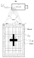
ATM60は、キャッシュカードを投入するカード口62、通帳を投入する通帳口63、現金を出し入れする現金口64、ATM60の操作画面表示部61等から構成される。
本実施例においては、上記実施例4で説明した構成、手順によりATM60に通信伝達する。通信伝達内容として、暗証番号の場合、携帯端末装置40で個人認証を実施の上、入力或いは予め入力した暗証番号を通信伝達する。また、ATM60より携帯端末装置40に認証状況や口座情報や振込み処理などの取扱い内容を通信伝達する。但し、現金収受や通帳記入はATM60で実施される。
このようにATM60に超音波通信装置を組み込むことにより、操作者はATM60を直接操作する必要が無く、また、携帯端末装置40側で操作するので秘匿性を保った状態で暗証番号入力や、預貯金や振込み処理が可能となる。また、携帯端末装置40の本来有しているカメラ31と表示部30をATM60のマイク19までの距離と方向を特定する機能に流用できるので、通信装置としての送信部を簡略化でき、装置コストを低減できる。
また、不特定多数の人が使用するATM60の表示画面に直接触れる必要がないので、衛生面の観点で操作者に安心感を与えることができる。また、ATM60の表示画面に複数の操作者の手指等が直接触れることがないので、表示画面が汚れにくくなる。
尚、本構成はATM60に限らず、自動販売機、自動券売機、POS等を対象としても同様な構成と効果が得られる。また、携帯端末装置40に限らず、後述の実施例で有っても良く、同様な構成と効果が得られる。
本実施例は、実施例3で記載した超音波通信装置の構成を、様々な情報処理装置の一例として眼鏡型端末装置(Head Mounted Display)に適用した場合の例を説明する。
図11は、本実施例における超音波通信装置を適用した眼鏡型端末装置70の構成を示す図である。図11に示すように、眼鏡型端末装置70は例えばメガネ型であり、画像表示や操作入力を受け付ける表示操作部71を含む。また、表示操作部71に表示されている画像は、空間上の虚像領域である表示部72にも表示される。眼鏡型端末装置70を装着した操作者の視野の様子を74で示す。
本実施例は、図11に示すように、本実施例における眼鏡型端末装置70を送信側とし、受信側装置500に対し情報伝達する構成である。虚像領域である表示部72に送信位置を特定する照準用画像73と、カメラ31によるカメラ画像75を表示する。もちろん虚像領域である表示部72に実空間が視認できる場合には、カメラ画像75は表示しない様にしても良い。操作者は、頭部の位置を調整してカメラ画像75或いは実空間に見える受信側装置500のマイク19のマーカを表示したカメラ画像75を照準用画像73に概ね一致させたところで、表示操作部71をタップすることで前述の実施例と同様に通信を開始し情報を伝達する。なお、タップ操作を、ボタン操作、音声入力、瞬きやジェスチャ操作等にしても良く、入力の意思を伝える手段であればいずれでも良い。
これにより、相手の特定と秘匿性を確保した通信を非接触ででき、眼鏡型端末装置70のデザインの自由度を向上しつつ、操作者の利便性を向上することができる。また、眼鏡型端末装置70の本来有しているカメラ31と表示部72を受信側装置500のマイク19までの距離と方向を特定する機能に流用できるので、通信装置としての送信部を簡略化でき、装置コストを低減できる。
また、本実施例においては、通信伝達の場合を例として説明した。その他、受信対象が音圧の力でSW動作する対象であれば、音圧を提示しSW動作を操作しても良く、また、瞬き等により視線を用いた遠隔操作としても良い。
本実施例は、実施例3で記載した超音波通信装置の構成を、様々な情報処理装置の一例として腕時計型端末装置に適用した場合の例を説明する。
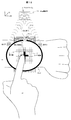
図12は、本実施例における超音波通信装置を適用した腕時計型端末装置80の構成を示す図である。図12に示すように、腕時計型端末装置80は、操作者の腕84に装着して使用する端末装置であり、画像表示や例えば操作者の手指86による操作入力を受け付ける表示操作部85を有する。
本実施例は、図12に示すように、本実施例における腕時計型端末装置80を送信側とし、受信側装置500に対し情報伝達する構成である。表示部30に送信位置を特定する照準用画像83と、カメラ31によるカメラ画像82を表示する。操作者は、腕84の位置を調整してカメラ画像82が受信側装置500のマイク19のマーカを表示したカメラ画像82を照準用画像83に概ね一致させたところで、手指86で照準用画像83をタップすることで上述の実施例と同様に通信を開始し情報を伝達する。なお、手指によるタップ操作を、ボタン操作、音声入力、ジェスチャ操作等にしても良く、入力の意思を伝える手段であればいずれでも良い。
これにより、相手の特定と秘匿性を確保した通信を非接触ででき、操作者の自由度や利便性を向上することができる。また、腕時計型端末装置80の本来有しているカメラ31と表示部30を受信側装置500のマイク19までの距離と方向を特定する機能に流用できるので、通信装置としての送信部を簡略化でき、装置コストを低減できる。
なお、上記実施例1~8に係る各機器は例示であり、送信部3、受信部4を組み込むことにより、目的に応じた通信により操作支援が実現される機器であればどのような機器であってもよい。例えば、自転車やオードバイ、一輪車、人間補助ロボット、ロボット、医療機器、医療介護ベッド等、人とインターフェースにより利便性が得られる装置に適用可能である。
また、上記実施例1~8における受信部4のマイク19に代わりに、手の平や手の甲全体として超音波の音圧を提示してもよい。この場合、手の平や手の甲に対し、提示位置でのみ、妨害波が無く超音波の音圧を伝達でき、それ以外の領域では妨害波により意味の成さない音圧が提示される。これにより、非接触で秘匿性を保ちながら情報を伝達することが可能になる。もちろん、受信者が音圧の変化を認識できる所であれば全身のいずれでも良い。
また、上記実施例1~8における超音波通信装置を、トイレの水洗ボタン、自動ドアの開閉ボタン、エレベータの階数指示ボタン等の様々なボタンに組込み、通信でボタン操作を実現しても良く、非接触でのボタン操作により、衛生面の確保や操作性を向上できる。
遊戯機器(パチンコ、パチスロ、ゲーム等)にも適用することができる。
遊戯機器(パチンコ、パチスロ、ゲーム等)にも適用することができる。
なお、本発明は上記した実施例に限定されるものではなく、様々な変形例が含まれる。例えば、上記した実施例は本発明をわかりやすく説明するために詳細に説明したものであり、必ずしも説明した全ての構成を備えるものに限定されるものではない。また、ある実施例の構成の一部に他の実施例の構成に置き換えることが可能であり、また、ある実施例の構成に他の実施例の構成を加えることも可能である。また、各実施例の構成の一部について、他の構成の追加、削除、置換をすることが可能である。
また、上記の各構成、機能、処理部等は、それらの一部又は全部を、例えば集積回路で設計する等によりハードウェアで実現しても良い。また、上記の各構成、機能等は、プロセッサがそれぞれの機能を実現するプログラムを解釈し、実行することによりソフトウェアで実現しても良い。各機能を実現するプログラム、テーブル、ファイル等の情報は、記憶媒体、ストレージ等に置くことができる。また、制御線や情報線は説明上必要と考えられるものを示しており、製品上必ずしも全ての制御線や情報線を示しているとは限らない。実際には殆ど全ての構成が相互に接続されていると考えても良い。
1、200、400…送信側装置、2、300、500…受信側装置、3…送信部、4…受信部、5…送信情報、6…位置情報、7…変調情報、8…制御部、9…発振部、10…変調部、11…時分割部、12…妨害信号生成部、13…加算部、14…減算部、15、16…距離補正部、PSP1、2…振動放射部(超音波素子)、ds1、2…伝搬情報(伝搬距離、伝搬時間)、dc1、2…距離補正情報、17、18…超音波WV1,WV2、19…マイク、20… 復調部、21…伝搬判定部、22…受信情報、23…補正情報、24…測距部、30…表示部、31…カメラ撮像部、40…携帯端末装置、42…カメラ画像、43…照準用画像、50…プロジェクタ、60…ATM、70、71…眼鏡型端末装置(眼鏡型端末装置)、80…腕時計型端末装置
Claims (10)
- 超音波で情報を伝達する超音波通信装置であって、
送信部に、
超音波を放出する複数の超音波素子と、
搬送波を送信情報で変調し変調波を出力する変調部と、
前記変調波を複数に時分割する時分割部と、
妨害信号の生成部と、
前記妨害信号を逆相関係となるよう前記分割した変調波に加減算する加減算部と、
前記複数の超音波素子から受信側装置のマイクまでの位置情報を補正する距離補正情報を得て、前記分割した変調波のそれぞれの位相遅延量と振幅を補正する距離補正部と、
前記送信部全体を制御する制御部と、を有し、
前記補正された分割した変調波のそれぞれで前記複数の超音波素子を駆動し超音波を放出することを特徴とする超音波通信装置。 - 請求項1に記載の超音波通信装置であって、
前記時分割部は、一定周期或いは不定周期のいずれかで時分割することを特徴とする超音波通信装置。 - 請求項1に記載の超音波通信装置であって、
前記妨害信号は、前記搬送波に重畳できる充分な周波数であって、前記分割した変調波の1部だけでは前記送信情報を復調できない周波数であって、
前記複数の超音波の位相が揃うことで互いに前記妨害信号を打ち消しあうことを特徴とする超音波通信装置。 - 請求項1に記載の超音波通信装置であって、
前記送信部と受信部を有し、
該受信部は、
送信側装置からの複数の超音波の合波信号を捕らえて再生波を出力するマイクと、
前記再生波を搬送波から分離して受信情報を抽出する復調部と、
前記再生波に残存する送信側装置から送信された妨害信号成分を抽出し、前記マイクに到達した複数の超音波の到達情報から求めた伝搬情報の補正量を示す補正情報を出力する伝搬判定部と、
を有することを特徴とする超音波通信装置。 - 請求項1に記載の超音波通信装置であって、
前記位置情報は、前記超音波素子から前記受信側装置のマイクまでの伝搬距離や伝搬時間の伝搬情報、または伝搬媒体情報、または前記伝搬情報の補正量を示す補正情報の少なくともいずれかであることを特徴とする超音波通信装置。 - 請求項1に記載の超音波通信装置であって、
LED光やレーザ光と光学センサを用いた光学式測距装置または音波を用いた測距部を有し、
該測距部により受信側装置のマイクまでの距離を計測し前記位置情報を生成することを特徴とする超音波通信装置。 - 請求項1に記載の超音波通信装置であって、
カメラ撮像部と、表示部を有し、
該表示部に照準用画像と、受信側装置のマイクをカメラ撮像したカメラ画像を表示し、前記照準用画像と前記カメラ画像が略一致するよう送信側装置を移動させ、前記位置情報を生成することを特徴とする超音波通信装置。 - 請求項7に記載の超音波通信装置を有した情報処理装置であって、
前記カメラ撮像部と前記表示部を、前記情報処理装置が本来有しているカメラ撮像部と表示部とで兼用したことを特徴とする情報処理装置。 - 超音波で情報を伝達する超音波通信方法であって、
超音波を放出する複数の超音波素子を有し、
搬送波を送信情報で変調し、
該変調した変調波を複数に時分割し、
妨害信号を生成し、
該妨害信号を逆相関係となるよう前記分割した変調波に加減算し、
前記複数の超音波素子から受信側装置のマイクまでの位置情報に対応して前記分割した変調波のそれぞれの位相遅延量と振幅を補正し、
前記補正された分割した変調波のそれぞれで前記複数の超音波素子を駆動し超音波を放出し、
前記複数の超音波素子からの超音波を集音した再生波は、前記複数の超音波の位相が揃うことで互いに前記妨害信号を打ち消しあうことを特徴とする超音波通信方法。 - 請求項9に記載の超音波通信方法であって、
前記受信側装置のマイクの位置以外では、前記複数の超音波素子からの超音波を集音した再生波は、前記複数の超音波の位相が揃わず前記妨害信号の影響で前記送信情報を再生できないことを特徴とする超音波通信方法。
Priority Applications (1)
| Application Number | Priority Date | Filing Date | Title |
|---|---|---|---|
| PCT/JP2015/069964 WO2017009911A1 (ja) | 2015-07-10 | 2015-07-10 | 超音波通信装置、超音波通信方法、並びにそれを用いた情報処理装置 |
Applications Claiming Priority (1)
| Application Number | Priority Date | Filing Date | Title |
|---|---|---|---|
| PCT/JP2015/069964 WO2017009911A1 (ja) | 2015-07-10 | 2015-07-10 | 超音波通信装置、超音波通信方法、並びにそれを用いた情報処理装置 |
Publications (1)
| Publication Number | Publication Date |
|---|---|
| WO2017009911A1 true WO2017009911A1 (ja) | 2017-01-19 |
Family
ID=57757861
Family Applications (1)
| Application Number | Title | Priority Date | Filing Date |
|---|---|---|---|
| PCT/JP2015/069964 Ceased WO2017009911A1 (ja) | 2015-07-10 | 2015-07-10 | 超音波通信装置、超音波通信方法、並びにそれを用いた情報処理装置 |
Country Status (1)
| Country | Link |
|---|---|
| WO (1) | WO2017009911A1 (ja) |
Cited By (3)
| Publication number | Priority date | Publication date | Assignee | Title |
|---|---|---|---|---|
| CN110830147A (zh) * | 2019-07-11 | 2020-02-21 | 东莞市普乔电子科技有限公司 | 一种防窃听窃录装置 |
| CN113905308A (zh) * | 2021-08-05 | 2022-01-07 | 钰太芯微电子科技(上海)有限公司 | 在线修调的mems麦克风及电子设备 |
| CN115101040A (zh) * | 2022-08-09 | 2022-09-23 | 物至科技(西安)有限公司 | 一种屏蔽智能设备麦克风的方法 |
Citations (2)
| Publication number | Priority date | Publication date | Assignee | Title |
|---|---|---|---|---|
| JP2003258691A (ja) * | 2002-03-06 | 2003-09-12 | Mitsubishi Electric Corp | 無線通信装置 |
| JP2009152838A (ja) * | 2007-12-20 | 2009-07-09 | Sumitomo Electric Ind Ltd | 通信システム |
-
2015
- 2015-07-10 WO PCT/JP2015/069964 patent/WO2017009911A1/ja not_active Ceased
Patent Citations (2)
| Publication number | Priority date | Publication date | Assignee | Title |
|---|---|---|---|---|
| JP2003258691A (ja) * | 2002-03-06 | 2003-09-12 | Mitsubishi Electric Corp | 無線通信装置 |
| JP2009152838A (ja) * | 2007-12-20 | 2009-07-09 | Sumitomo Electric Ind Ltd | 通信システム |
Non-Patent Citations (1)
| Title |
|---|
| "A Study on Signal Hiding in Secret Communication System Using Multi-Antenna Transmission", IEICE TECHNICAL REPORT. A·P, ANTENNA·DENPA, vol. 109, no. 183, 27 August 2009 (2009-08-27), pages 125 - 130 * |
Cited By (4)
| Publication number | Priority date | Publication date | Assignee | Title |
|---|---|---|---|---|
| CN110830147A (zh) * | 2019-07-11 | 2020-02-21 | 东莞市普乔电子科技有限公司 | 一种防窃听窃录装置 |
| CN113905308A (zh) * | 2021-08-05 | 2022-01-07 | 钰太芯微电子科技(上海)有限公司 | 在线修调的mems麦克风及电子设备 |
| CN113905308B (zh) * | 2021-08-05 | 2023-06-06 | 钰太芯微电子科技(上海)有限公司 | 在线修调的mems麦克风及电子设备 |
| CN115101040A (zh) * | 2022-08-09 | 2022-09-23 | 物至科技(西安)有限公司 | 一种屏蔽智能设备麦克风的方法 |
Similar Documents
| Publication | Publication Date | Title |
|---|---|---|
| US11265635B2 (en) | Wearable communication device | |
| EP2528354B1 (en) | Voice and position localization | |
| US8849185B2 (en) | Hybrid audio delivery system and method therefor | |
| KR20190025382A (ko) | 전자장치 | |
| US10945068B2 (en) | Ultrasonic wave-based voice signal transmission system and method | |
| CN106687885A (zh) | 用于信使处理的可穿戴设备及其使用方法 | |
| JP2011507088A (ja) | タッチ感知式デバイス | |
| KR20170049279A (ko) | 이동 단말기 | |
| KR101667733B1 (ko) | 이동단말기 및 그 제어방법 | |
| WO2017009911A1 (ja) | 超音波通信装置、超音波通信方法、並びにそれを用いた情報処理装置 | |
| EP3886413B1 (en) | Mobile terminal | |
| Xu et al. | mmEar: Push the limit of COTS mmWave eavesdropping on headphones | |
| CN108769868A (zh) | 基于频分超声参量阵的手机屏下听筒实现方法与装置 | |
| KR20160070529A (ko) | 웨어러블 디바이스 | |
| Chen et al. | A comprehensive survey of side-channel sound-sensing methods | |
| KR102355194B1 (ko) | 수신 장치 및 방법, 송신 장치 및 방법, 및 프로그램 | |
| JP2009200772A (ja) | 水中通信装置および水中通信システム | |
| CN108632718B (zh) | 一种音频共享的方法及系统 | |
| US20110123032A1 (en) | Single sound transmission apparatus using human body communicaton | |
| KR20150140050A (ko) | 이동단말기 및 그 제어방법 | |
| KR20170011618A (ko) | 이동 단말기 및 그 제어방법 | |
| KR20160080538A (ko) | 이동 단말기 및 그 제어방법 | |
| JP4664341B2 (ja) | 赤外線通信装置 | |
| CN113573209A (zh) | 音频处理方法、装置及电子设备 | |
| KR20160007048A (ko) | 전자 디바이스 및 그 제어방법 |
Legal Events
| Date | Code | Title | Description |
|---|---|---|---|
| 121 | Ep: the epo has been informed by wipo that ep was designated in this application |
Ref document number: 15898227 Country of ref document: EP Kind code of ref document: A1 |
|
| NENP | Non-entry into the national phase |
Ref country code: DE |
|
| NENP | Non-entry into the national phase |
Ref country code: JP |
|
| 122 | Ep: pct application non-entry in european phase |
Ref document number: 15898227 Country of ref document: EP Kind code of ref document: A1 |