WO2017007013A1 - Lithium ion secondary battery - Google Patents
Lithium ion secondary battery Download PDFInfo
- Publication number
- WO2017007013A1 WO2017007013A1 PCT/JP2016/070253 JP2016070253W WO2017007013A1 WO 2017007013 A1 WO2017007013 A1 WO 2017007013A1 JP 2016070253 W JP2016070253 W JP 2016070253W WO 2017007013 A1 WO2017007013 A1 WO 2017007013A1
- Authority
- WO
- WIPO (PCT)
- Prior art keywords
- negative electrode
- graphite
- secondary battery
- ion secondary
- silicon oxide
- Prior art date
Links
Images


Classifications
-
- H—ELECTRICITY
- H01—ELECTRIC ELEMENTS
- H01M—PROCESSES OR MEANS, e.g. BATTERIES, FOR THE DIRECT CONVERSION OF CHEMICAL ENERGY INTO ELECTRICAL ENERGY
- H01M10/00—Secondary cells; Manufacture thereof
- H01M10/05—Accumulators with non-aqueous electrolyte
- H01M10/052—Li-accumulators
- H01M10/0525—Rocking-chair batteries, i.e. batteries with lithium insertion or intercalation in both electrodes; Lithium-ion batteries
-
- H—ELECTRICITY
- H01—ELECTRIC ELEMENTS
- H01M—PROCESSES OR MEANS, e.g. BATTERIES, FOR THE DIRECT CONVERSION OF CHEMICAL ENERGY INTO ELECTRICAL ENERGY
- H01M10/00—Secondary cells; Manufacture thereof
- H01M10/05—Accumulators with non-aqueous electrolyte
- H01M10/056—Accumulators with non-aqueous electrolyte characterised by the materials used as electrolytes, e.g. mixed inorganic/organic electrolytes
- H01M10/0564—Accumulators with non-aqueous electrolyte characterised by the materials used as electrolytes, e.g. mixed inorganic/organic electrolytes the electrolyte being constituted of organic materials only
- H01M10/0566—Liquid materials
- H01M10/0567—Liquid materials characterised by the additives
-
- H—ELECTRICITY
- H01—ELECTRIC ELEMENTS
- H01M—PROCESSES OR MEANS, e.g. BATTERIES, FOR THE DIRECT CONVERSION OF CHEMICAL ENERGY INTO ELECTRICAL ENERGY
- H01M10/00—Secondary cells; Manufacture thereof
- H01M10/05—Accumulators with non-aqueous electrolyte
- H01M10/056—Accumulators with non-aqueous electrolyte characterised by the materials used as electrolytes, e.g. mixed inorganic/organic electrolytes
- H01M10/0564—Accumulators with non-aqueous electrolyte characterised by the materials used as electrolytes, e.g. mixed inorganic/organic electrolytes the electrolyte being constituted of organic materials only
- H01M10/0566—Liquid materials
- H01M10/0569—Liquid materials characterised by the solvents
-
- H—ELECTRICITY
- H01—ELECTRIC ELEMENTS
- H01M—PROCESSES OR MEANS, e.g. BATTERIES, FOR THE DIRECT CONVERSION OF CHEMICAL ENERGY INTO ELECTRICAL ENERGY
- H01M10/00—Secondary cells; Manufacture thereof
- H01M10/05—Accumulators with non-aqueous electrolyte
- H01M10/058—Construction or manufacture
- H01M10/0585—Construction or manufacture of accumulators having only flat construction elements, i.e. flat positive electrodes, flat negative electrodes and flat separators
-
- H—ELECTRICITY
- H01—ELECTRIC ELEMENTS
- H01M—PROCESSES OR MEANS, e.g. BATTERIES, FOR THE DIRECT CONVERSION OF CHEMICAL ENERGY INTO ELECTRICAL ENERGY
- H01M4/00—Electrodes
- H01M4/02—Electrodes composed of, or comprising, active material
- H01M4/13—Electrodes for accumulators with non-aqueous electrolyte, e.g. for lithium-accumulators; Processes of manufacture thereof
- H01M4/133—Electrodes based on carbonaceous material, e.g. graphite-intercalation compounds or CFx
-
- H—ELECTRICITY
- H01—ELECTRIC ELEMENTS
- H01M—PROCESSES OR MEANS, e.g. BATTERIES, FOR THE DIRECT CONVERSION OF CHEMICAL ENERGY INTO ELECTRICAL ENERGY
- H01M4/00—Electrodes
- H01M4/02—Electrodes composed of, or comprising, active material
- H01M4/36—Selection of substances as active materials, active masses, active liquids
- H01M4/48—Selection of substances as active materials, active masses, active liquids of inorganic oxides or hydroxides
-
- H—ELECTRICITY
- H01—ELECTRIC ELEMENTS
- H01M—PROCESSES OR MEANS, e.g. BATTERIES, FOR THE DIRECT CONVERSION OF CHEMICAL ENERGY INTO ELECTRICAL ENERGY
- H01M4/00—Electrodes
- H01M4/02—Electrodes composed of, or comprising, active material
- H01M4/36—Selection of substances as active materials, active masses, active liquids
- H01M4/58—Selection of substances as active materials, active masses, active liquids of inorganic compounds other than oxides or hydroxides, e.g. sulfides, selenides, tellurides, halogenides or LiCoFy; of polyanionic structures, e.g. phosphates, silicates or borates
- H01M4/583—Carbonaceous material, e.g. graphite-intercalation compounds or CFx
- H01M4/587—Carbonaceous material, e.g. graphite-intercalation compounds or CFx for inserting or intercalating light metals
-
- H—ELECTRICITY
- H01—ELECTRIC ELEMENTS
- H01M—PROCESSES OR MEANS, e.g. BATTERIES, FOR THE DIRECT CONVERSION OF CHEMICAL ENERGY INTO ELECTRICAL ENERGY
- H01M4/00—Electrodes
- H01M4/02—Electrodes composed of, or comprising, active material
- H01M4/62—Selection of inactive substances as ingredients for active masses, e.g. binders, fillers
- H01M4/621—Binders
- H01M4/622—Binders being polymers
- H01M4/623—Binders being polymers fluorinated polymers
-
- H—ELECTRICITY
- H01—ELECTRIC ELEMENTS
- H01M—PROCESSES OR MEANS, e.g. BATTERIES, FOR THE DIRECT CONVERSION OF CHEMICAL ENERGY INTO ELECTRICAL ENERGY
- H01M4/00—Electrodes
- H01M4/02—Electrodes composed of, or comprising, active material
- H01M4/62—Selection of inactive substances as ingredients for active masses, e.g. binders, fillers
- H01M4/624—Electric conductive fillers
- H01M4/625—Carbon or graphite
-
- H—ELECTRICITY
- H01—ELECTRIC ELEMENTS
- H01M—PROCESSES OR MEANS, e.g. BATTERIES, FOR THE DIRECT CONVERSION OF CHEMICAL ENERGY INTO ELECTRICAL ENERGY
- H01M4/00—Electrodes
- H01M4/02—Electrodes composed of, or comprising, active material
- H01M4/64—Carriers or collectors
- H01M4/70—Carriers or collectors characterised by shape or form
-
- B—PERFORMING OPERATIONS; TRANSPORTING
- B82—NANOTECHNOLOGY
- B82Y—SPECIFIC USES OR APPLICATIONS OF NANOSTRUCTURES; MEASUREMENT OR ANALYSIS OF NANOSTRUCTURES; MANUFACTURE OR TREATMENT OF NANOSTRUCTURES
- B82Y30/00—Nanotechnology for materials or surface science, e.g. nanocomposites
-
- H—ELECTRICITY
- H01—ELECTRIC ELEMENTS
- H01M—PROCESSES OR MEANS, e.g. BATTERIES, FOR THE DIRECT CONVERSION OF CHEMICAL ENERGY INTO ELECTRICAL ENERGY
- H01M4/00—Electrodes
- H01M4/02—Electrodes composed of, or comprising, active material
- H01M2004/021—Physical characteristics, e.g. porosity, surface area
-
- H—ELECTRICITY
- H01—ELECTRIC ELEMENTS
- H01M—PROCESSES OR MEANS, e.g. BATTERIES, FOR THE DIRECT CONVERSION OF CHEMICAL ENERGY INTO ELECTRICAL ENERGY
- H01M4/00—Electrodes
- H01M4/02—Electrodes composed of, or comprising, active material
- H01M2004/026—Electrodes composed of, or comprising, active material characterised by the polarity
- H01M2004/027—Negative electrodes
-
- H—ELECTRICITY
- H01—ELECTRIC ELEMENTS
- H01M—PROCESSES OR MEANS, e.g. BATTERIES, FOR THE DIRECT CONVERSION OF CHEMICAL ENERGY INTO ELECTRICAL ENERGY
- H01M4/00—Electrodes
- H01M4/02—Electrodes composed of, or comprising, active material
- H01M2004/026—Electrodes composed of, or comprising, active material characterised by the polarity
- H01M2004/028—Positive electrodes
-
- H—ELECTRICITY
- H01—ELECTRIC ELEMENTS
- H01M—PROCESSES OR MEANS, e.g. BATTERIES, FOR THE DIRECT CONVERSION OF CHEMICAL ENERGY INTO ELECTRICAL ENERGY
- H01M2300/00—Electrolytes
- H01M2300/0017—Non-aqueous electrolytes
- H01M2300/0025—Organic electrolyte
- H01M2300/0028—Organic electrolyte characterised by the solvent
-
- Y—GENERAL TAGGING OF NEW TECHNOLOGICAL DEVELOPMENTS; GENERAL TAGGING OF CROSS-SECTIONAL TECHNOLOGIES SPANNING OVER SEVERAL SECTIONS OF THE IPC; TECHNICAL SUBJECTS COVERED BY FORMER USPC CROSS-REFERENCE ART COLLECTIONS [XRACs] AND DIGESTS
- Y02—TECHNOLOGIES OR APPLICATIONS FOR MITIGATION OR ADAPTATION AGAINST CLIMATE CHANGE
- Y02E—REDUCTION OF GREENHOUSE GAS [GHG] EMISSIONS, RELATED TO ENERGY GENERATION, TRANSMISSION OR DISTRIBUTION
- Y02E60/00—Enabling technologies; Technologies with a potential or indirect contribution to GHG emissions mitigation
- Y02E60/10—Energy storage using batteries
-
- Y—GENERAL TAGGING OF NEW TECHNOLOGICAL DEVELOPMENTS; GENERAL TAGGING OF CROSS-SECTIONAL TECHNOLOGIES SPANNING OVER SEVERAL SECTIONS OF THE IPC; TECHNICAL SUBJECTS COVERED BY FORMER USPC CROSS-REFERENCE ART COLLECTIONS [XRACs] AND DIGESTS
- Y02—TECHNOLOGIES OR APPLICATIONS FOR MITIGATION OR ADAPTATION AGAINST CLIMATE CHANGE
- Y02P—CLIMATE CHANGE MITIGATION TECHNOLOGIES IN THE PRODUCTION OR PROCESSING OF GOODS
- Y02P70/00—Climate change mitigation technologies in the production process for final industrial or consumer products
- Y02P70/50—Manufacturing or production processes characterised by the final manufactured product
-
- Y—GENERAL TAGGING OF NEW TECHNOLOGICAL DEVELOPMENTS; GENERAL TAGGING OF CROSS-SECTIONAL TECHNOLOGIES SPANNING OVER SEVERAL SECTIONS OF THE IPC; TECHNICAL SUBJECTS COVERED BY FORMER USPC CROSS-REFERENCE ART COLLECTIONS [XRACs] AND DIGESTS
- Y02—TECHNOLOGIES OR APPLICATIONS FOR MITIGATION OR ADAPTATION AGAINST CLIMATE CHANGE
- Y02T—CLIMATE CHANGE MITIGATION TECHNOLOGIES RELATED TO TRANSPORTATION
- Y02T10/00—Road transport of goods or passengers
- Y02T10/60—Other road transportation technologies with climate change mitigation effect
- Y02T10/70—Energy storage systems for electromobility, e.g. batteries
Definitions
- the present invention relates to a lithium ion secondary battery, a manufacturing method thereof, and a vehicle using the lithium ion secondary battery.
- Lithium ion secondary batteries are characterized by their small size and large capacity, and they have been widely used as power sources for electronic devices such as mobile phones and laptop computers, and have contributed to improving the convenience of portable IT devices.
- the use in a larger application such as a power source for driving a motorcycle or an automobile or a storage battery for a smart grid has attracted attention.
- As demand for lithium-ion secondary batteries increases and it is used in various fields, it is possible to use batteries with higher energy density, life characteristics that can withstand long-term use, and a wide range of temperature conditions. Such characteristics are required.
- carbon-based materials are used for the negative electrode of lithium ion secondary batteries, but in order to increase the energy density of the battery, silicon-based materials having a large amount of occlusion / release of lithium ions per unit volume are used as the negative electrode. It is being considered for use. However, since the silicon-based material expands and contracts due to repeated charging and discharging of lithium and deteriorates due to this, there is a problem in the cycle characteristics of the battery.
- Patent Document 1 discloses (a) a negative electrode active material such as silicon oxide coated with a carbon material, (b) a graphite-based carbon material, and (c) acetylene black, ketjen black, and a powder containing graphite crystals.
- a negative electrode active material such as silicon oxide coated with a carbon material
- a graphite-based carbon material such as graphite-based carbon material
- acetylene black, ketjen black acetylene black, ketjen black
- a powder containing graphite crystals a powder containing graphite crystals.
- the rate characteristics and cycle characteristics of the battery can be improved by using a negative electrode including a carbon material other than graphite-based carbon material such as conductive carbon fiber.
- An object of the present invention is to provide a lithium ion secondary battery with improved cycle characteristics, with less reduction in discharge capacity and increase in internal resistance when the silicon-based material, which is the above-described problem, is used for a negative electrode. .
- the lithium ion secondary battery of the present invention has a carbon nanotube having a peak at 2600 to 2800 cm ⁇ 1 in a Raman spectrum obtained by Raman spectroscopy, graphite, and a composition expressed by SiO x (where 0 ⁇ x ⁇ 2). And a silicon oxide.
- a lithium ion secondary battery having improved cycle characteristics can be provided.
- Embodiments of the present invention will be described for each member of a lithium ion secondary battery.
- the negative electrode has a structure in which a negative electrode active material is laminated on a current collector as a negative electrode active material layer integrated with a negative electrode binder.
- the negative electrode active material is a material capable of reversibly occluding and releasing lithium ions accompanying charge / discharge contained in the negative electrode.
- the negative electrode includes graphite and silicon oxide as the negative electrode active material, and carbon nanotubes as the conductive material.
- the graphite used may be either natural graphite or artificial graphite.
- the shape of graphite is not particularly limited and may be any. Examples of natural graphite include scaly graphite, scaly graphite, earthy graphite, and the like.
- Artificial graphite includes spherical artificial graphite, flake shaped artificial graphite, and spherical artificial graphite such as MCMB (mesophase micro beads).
- the graphite used may be coated with a carbon material or the like.
- the median diameter D 50G of the graphite particles is preferably in the range of 5.0 ⁇ m ⁇ D 50G ⁇ 25.0 ⁇ m.
- the negative electrode preferably contains graphite in an amount of 50% by mass or more, more preferably 70% by mass or more, based on the total amount of the negative electrode active material contained in the negative electrode. Moreover, it is preferable that a negative electrode contains 97 mass% or less with respect to the total amount of the negative electrode active material contained in a negative electrode.
- the silicon oxide used has a composition represented by SiO x (where 0 ⁇ x ⁇ 2).
- a particularly preferred silicon oxide is SiO. It is preferable that the surface of the silicon oxide is coated with a carbon material. By using carbon-coated silicon oxide particles, a secondary battery having excellent cycle characteristics can be obtained.
- the median diameter D 50S of the silicon oxide particles is preferably in the range of 0.5 ⁇ m ⁇ D 50S ⁇ 10.0 ⁇ m.
- the negative electrode preferably contains silicon oxide in an amount of 1% by mass or more, more preferably 3% by mass or more, based on the total amount of the negative electrode active material contained in the negative electrode. Further, the negative electrode preferably contains silicon oxide in an amount of 20% by mass or less, more preferably 10% by mass or less, based on the total amount of the negative electrode active material contained in the negative electrode.
- a carbon nanotube is a carbon material formed from a planar graphene sheet having a six-membered ring of carbon, and functions as a conductive material in a secondary battery.
- the carbon nanotube is a flat graphene sheet having a six-membered ring of carbon formed in a cylindrical shape, and may be a single layer or a coaxial multilayer structure. Further, both ends of the cylindrical carbon nanotube may be open, but may be closed with a hemispherical fullerene containing a 5-membered or 7-membered carbon ring.
- the diameter of the outermost cylinder of the carbon nanotube is preferably 0.5 nm or more and 50 nm or less, for example.
- the average length D 50C of the carbon nanotubes is preferably in the range of 0.05 ⁇ m ⁇ D 50C ⁇ 5.0 ⁇ m.
- Carbon nanotubes are contained in the negative electrode in an amount of preferably 0.5% by mass or more, more preferably 1.0% by mass or more, based on the total amount of the negative electrode active material contained in the negative electrode.
- Carbon nanotubes are contained in the negative electrode in an amount of preferably 20% by mass or less, more preferably 5% by mass or less, based on the total amount of the negative electrode active material contained in the negative electrode.
- Carbon materials having a graphene layer such as graphite and carbon nanotubes can confirm characteristics such as crystallinity and the number of layers by Raman spectroscopy.
- Raman spectrum obtained by Raman spectroscopy peaks (in this case, also referred to as a 2D band) occurring in the range of 2600 ⁇ 2800 cm -1 and a peak derived from the graphene plane vibration that occur in the range of 1500 ⁇ 1700 cm -1 (
- the peak derived from a defect in the crystal structure that occurs in the range of 1000 to 1400 cm ⁇ 1 is generally used for evaluating the crystal structure of the graphene layer. Is done.
- a carbon material having a large G band peak intensity has high crystallinity, and a carbon material having a large D band peak intensity tends to have disordered crystals and structural defects. Therefore, the ratio (I G / I D ) between the peak intensity (I G ) of the G band and the peak intensity (I D ) of the D band is used as an index of crystallinity.
- the 2D band can be used as an index.
- the 2D band is known as a D-band overtone mode.
- the present inventor investigated the Raman spectroscopic measurement and battery characteristics of graphite, silicon oxide, and carbon nanotubes in detail, and I G / ID is 2D band peak intensity (I 2D ) and D band peak intensity ( It has been found that there is a relationship with the ratio of I D ) (I 2D / I D ). There is a relatively positive correlation between I G / ID and I 2D / ID , and when I G / ID is large, I 2D / ID is also large.
- the present inventor examines the Raman spectroscopic measurement results and battery characteristics of the carbon material in detail, and the 2D band does not simply follow the overtone mode of the D band. We found that there are types that follow sensitively and types that do not follow D band very much. In order to increase the peak intensity of the 2D band without correlating with the D band, for example, it is conceivable to increase the temperature at the time of generating the graphite material or the carbon nanotube, and further increase the crystallinity.
- FIGS. 3 to 5 show examples of Raman spectra of graphite, silicon oxide and carbon nanotube used in this embodiment.
- a carbon nanotube having a 2D band in the Raman spectrum is used for the negative electrode.
- the cycle characteristics of the battery can be improved.
- the improvement mechanism of the negative electrode due to the presence or absence of the 2D band is not well understood in detail, but the material having a peak in the 2D band can easily form a low resistance SEI (Solid electrolyte interface) film on the carbon surface, In addition, it has an effect of increasing the replenishability of the electrolyte, and is thought to improve cycle characteristics.
- silicon oxide contained in the negative electrode (however, silicon oxide is preferably carbon-coated.
- the Raman spectrum of silicon oxide is defined below. In this case, silicon oxide is carbon-coated. It is intended to define the Raman spectrum obtained by Raman spectroscopic measurement of carbon-coated silicon oxide particles.)
- carbon nanotubes have peak intensity ratios described below when the Raman spectroscopic measurement is performed. And / or exhibiting a Raman spectrum satisfying the peak area ratio is preferable for improving the cycle retention rate of the battery and suppressing the rate of increase in resistance.
- the carbon nanotubes having the peak ratios described below are likely to form a conductive path between the graphite particles and the silicon oxide particles, and the silicon oxide is considered to easily reduce the destruction of the carbon coat on the graphite surface. . Furthermore, graphite and silicon oxide showing the peak ratio described below can follow the expansion and contraction at the time of charging and discharging because the carbon nanotubes showing the peak ratio described below are present in the gaps between these particles, Even if the damage of graphite is particularly small, the cycle characteristics of the battery are improved.
- the ratio (I G / I D ) of the peak intensity (I G ) of the G band and the peak intensity (I D ) of the D band is expressed as I GG / I GD for graphite
- the peak intensity ratio of graphite, silicon oxide and carbon nanotube contained in the negative electrode is at least one of the following formulas It is preferable to satisfy
- I GG / I GD is preferably higher, I SG / I SD is preferably closer to 1.0, and I CG / I CD is preferably closer to I SG / I SD . Therefore, it is preferable that the peak intensity ratio of graphite, silicon oxide, and carbon nanotube contained in the negative electrode satisfy at least one of the following formulas, and more preferably satisfy all the following formulas.
- the ratio (S G / S D ) of the peak area (S G ) of the G band and the peak area (S D ) of the D band in the Raman spectrum obtained by Raman spectroscopy measurement is expressed as S GG / S GD for graphite
- the peak area ratio of graphite, silicon oxide and carbon nanotube contained in the negative electrode is at least one of the following formulae It is preferable to satisfy
- the peak area ratio of graphite, silicon oxide and carbon nanotube contained in the negative electrode preferably satisfies at least one of the following formulas, and more preferably satisfies all the following formulas.
- silicon oxide is expressed as I S2D / I SD and carbon nanotube is expressed as I C2D / I CD
- the peak intensity ratio of graphite, silicon oxide, and carbon nanotube contained in the negative electrode is at least one of the following formulas: It is preferable to satisfy
- I G2D / I GD is preferably higher, I S2D / I SD is preferably closer to 1.0, and I C2D / I CD is preferably closer to I S2D / I SD . Therefore, it is preferable that the peak intensity ratio of graphite, silicon oxide, and carbon nanotube contained in the negative electrode satisfy at least one of the following formulas, and more preferably satisfy all the following formulas.
- the ratio of the peak area of peak area (S 2D) and D-band of 2D band in the Raman spectrum obtained by Raman spectroscopy (S D) (S 2D / S D), for the graphite expressed as S G2D / S GD
- S S2D / S SD silicon oxide is expressed as S S2D / S SD
- carbon nanotube is expressed as S C2D / S CD
- the peak area ratio of graphite, silicon oxide, and carbon nanotube contained in the negative electrode is at least one of the following formulae: It is preferable to satisfy
- the peak area ratio of graphite, silicon oxide and carbon nanotube contained in the negative electrode preferably satisfies at least one of the following formulas, and more preferably satisfies all the following formulas.
- the peak intensity of the 2D band (I 2D), 2600 ⁇ means a peak intensity of the highest peak in the range of 2800 cm -1
- the peak intensity of the highest peak in the range means the peak intensity of the G band (I G ) means the peak intensity of the highest peak in the range of 1500 to 1700 cm ⁇ 1 .
- the peak area of 2D band means a peak area in the range of 2600 ⁇ 2800 cm -1
- the peak area of D band (S D)
- the G band peak area (S G ) means a peak area in the range of 1500 to 1700 cm ⁇ 1 .
- the cycle characteristics may be further improved by controlling the particle diameters of graphite and silicon oxide and the length of the carbon nanotubes.
- the median diameter of the graphite particles D 50G when the average length of the median diameter of the silicon oxide particles D 50S and carbon nanotubes was D 50C, the respective range, 5.0 ⁇ m ⁇ D 50G ⁇ 25.0 ⁇ m 0.5 ⁇ m ⁇ D 50S ⁇ 10.0 ⁇ m 0.05 ⁇ m ⁇ D 50C ⁇ 5.0 ⁇ m
- D 50G / D 50S is in the range of 0.5 to 2.0 and D 50G / D 50C is in the range of 10 to 250.
- preferable cycle characteristics can be obtained when the particle diameter and the length are within the above ranges. This is presumed to be because the penetration and permeability of the electrolytic solution are particularly improved within the above range.
- a negative electrode active material other than graphite and silicon oxide can be used in addition to the negative electrode.
- the additional negative electrode active material is not particularly limited and known materials can be used.
- silicon-based materials such as silicon alloys, silicon composite oxides and silicon nitrides, carbon-based materials such as non-graphitizable carbon and amorphous carbon Materials, metals such as Al, Pb, Sn, In, Bi, Ag, Ba, Ca, Hg, Pd, Pt, Te, Zn, La and alloys thereof, and aluminum oxide, tin oxide, indium oxide, zinc oxide, oxide Examples thereof include metal oxides such as lithium, and these can be used alone or in combination of two or more.
- a conductive material may be added and added.
- the additional conductive material include scale-like, rod-like, and fibrous carbonaceous fine particles such as carbon black, acetylene black, ketjen black, and vapor grown carbon fiber.
- binder for the negative electrode polyvinylidene fluoride, vinylidene fluoride-hexafluoropropylene copolymer, vinylidene fluoride-tetrafluoroethylene copolymer, polytetrafluoroethylene, polypropylene, polyethylene, polyimide, polyamideimide, etc. are used. be able to.
- SBR styrene butadiene rubber
- a thickener such as carboxymethyl cellulose (CMC) can also be used.
- the amount of the negative electrode binder used is preferably 0.5 to 20 parts by mass with respect to 100 parts by mass of the negative electrode active material, from the viewpoint of sufficient binding force and high energy in a trade-off relationship.
- the above binder for negative electrode can also be used as a mixture.
- the negative electrode current collector aluminum, nickel, copper, silver, and alloys thereof are preferable in view of electrochemical stability.
- Examples of the shape include foil, flat plate, and mesh.
- the negative electrode can be produced by forming a negative electrode active material layer containing a negative electrode active material and a negative electrode binder on a negative electrode current collector.
- Examples of the method for forming the negative electrode active material layer include a doctor blade method, a die coater method, a CVD method, and a sputtering method.
- a thin film of aluminum, nickel, or an alloy thereof may be formed by a method such as vapor deposition or sputtering to form a negative electrode current collector.
- the positive electrode includes a positive electrode active material capable of reversibly occluding and releasing lithium ions during charge and discharge, and the positive electrode active material is laminated on the current collector as a positive electrode active material layer integrated with a positive electrode binder. It has a structure.
- the positive electrode active material in the present embodiment is not particularly limited as long as it is a material capable of occluding and releasing lithium, but it is preferable to include a high capacity compound from the viewpoint of increasing the energy density.
- the high-capacity compound include lithium-nickel composite oxide in which a part of Ni in lithium nickelate (LiNiO 2 ) is substituted with another metal element, and a layered lithium-nickel composite oxide represented by the following formula (A) Things are preferred.
- the compound represented by the formula (A) has a high Ni content, that is, in the formula (A), x is preferably less than 0.5, and more preferably 0.4 or less.
- LiNi 0.8 Co 0.05 Mn 0.15 O 2 , LiNi 0.8 Co 0.1 Mn 0.1 O 2 , LiNi 0.8 Co 0.15 Al 0.05 O 2, LiNi 0.8 Co 0.1 Al can be preferably used 0.1 O 2 or the like.
- LiNi 0.4 Co 0.3 Mn 0.3 O 2 (abbreviated as NCM433), LiNi 1/3 Co 1/3 Mn 1/3 O 2 , LiNi 0.5 Co 0.2 Mn 0.3 O 2 (abbreviated as NCM523), LiNi 0.5 Co 0.3 Mn 0.2 O 2 (abbreviated as NCM532), etc. (however, the content of each transition metal in these compounds varies by about 10%) Can also be included).
- two or more compounds represented by the formula (A) may be used as a mixture.
- NCM532 or NCM523 and NCM433 range from 9: 1 to 1: 9 (typically 2 It is also preferable to use a mixture in 1).
- a material having a high Ni content (x is 0.4 or less) and a material having a Ni content not exceeding 0.5 (x is 0.5 or more, for example, NCM433) are mixed. As a result, a battery having a high capacity and high thermal stability can be formed.
- the positive electrode active material for example, LiMnO 2 , Li x Mn 2 O 4 (0 ⁇ x ⁇ 2), Li 2 MnO 3 , Li x Mn 1.5 Ni 0.5 O 4 (0 ⁇ x ⁇ 2) Lithium manganate having a layered structure or spinel structure such as LiCoO 2 or a part of these transition metals replaced with another metal; Li in these lithium transition metal oxides more than the stoichiometric composition And those having an olivine structure such as LiFePO 4 .
- any of the positive electrode active materials described above can be used alone or in combination of two or more.
- polyvinylidene fluoride, vinylidene fluoride-hexafluoropropylene copolymer, vinylidene fluoride-tetrafluoroethylene copolymer, polytetrafluoroethylene, polypropylene, polyethylene, polyimide, polyamideimide, etc. are used. be able to.
- styrene butadiene rubber (SBR) and the like can be mentioned.
- SBR styrene butadiene rubber
- a thickener such as carboxymethyl cellulose (CMC) can also be used.
- polyvinylidene fluoride or polytetrafluoroethylene is preferable, and polyvinylidene fluoride is more preferable.
- the above binder for positive electrode can also be used by mixing.
- the amount of the positive electrode binder used is preferably 2 to 10 parts by mass with respect to 100 parts by mass of the positive electrode active material from the viewpoints of “sufficient binding force” and “higher energy” which are in a trade-off relationship. .
- a conductive material may be added to the coating layer containing the positive electrode active material for the purpose of reducing impedance.
- the conductive material include scaly, rod-like, and fibrous carbonaceous fine particles, such as graphite, carbon black, acetylene black, and vapor grown carbon fiber.
- the positive electrode current collector aluminum, nickel, copper, silver, and alloys thereof are preferable in view of electrochemical stability.
- the shape include foil, flat plate, and mesh.
- a current collector using aluminum, an aluminum alloy, or an iron / nickel / chromium / molybdenum-based stainless steel is preferable.
- the positive electrode can be produced by forming a positive electrode active material layer containing a positive electrode active material and a positive electrode binder on a positive electrode current collector.
- Examples of the method for forming the positive electrode active material layer include a doctor blade method, a die coater method, a CVD method, and a sputtering method.
- a thin film of aluminum, nickel, or an alloy thereof may be formed by a method such as vapor deposition or sputtering to form a positive electrode current collector.
- Electrode Although it does not specifically limit as electrolyte solution of the lithium ion secondary battery which concerns on this embodiment, The nonaqueous electrolyte solution containing the nonaqueous solvent and supporting salt which are stable in the operating potential of a battery is preferable.
- non-aqueous solvents examples include propylene carbonate (PC), ethylene carbonate (EC), butylene carbonate (BC) and other cyclic carbonates; dimethyl carbonate (DMC), diethyl carbonate (DEC), ethyl methyl carbonate (EMC), Chain carbonates such as dipropyl carbonate (DPC); propylene carbonate derivatives, aliphatic carboxylic acid esters such as methyl formate, methyl acetate and ethyl propionate; ethers such as diethyl ether and ethyl propyl ether; trimethyl phosphate; Aprotic organic solvents such as phosphate esters such as triethyl phosphate, tripropyl phosphate, trioctyl phosphate and triphenyl phosphate, and fluorine compounds in which at least some of the hydrogen atoms of these compounds are substituted with fluorine atoms.
- aprotic organic solvents and the like.
- cyclic such as ethylene carbonate (EC), propylene carbonate (PC), butylene carbonate (BC), dimethyl carbonate (DMC), diethyl carbonate (DEC), ethyl methyl carbonate (MEC), dipropyl carbonate (DPC), etc.
- chain carbonates are included.
- Non-aqueous solvents can be used alone or in combination of two or more.
- the supporting salts include LiPF 6 , LiAsF 6 , LiAlCl 4 , LiClO 4 , LiBF 4 , LiSbF 6 , LiCF 3 SO 3 , LiC 4 F 9 SO 3 , LiC (CF 3 SO 2 ) 3 , LiN (CF 3 SO 2 ) A lithium salt such as 2 .
- the supporting salt can be used singly or in combination of two or more. LiPF 6 is preferable from the viewpoint of cost reduction.
- the electrolytic solution can further contain an additive.
- an additive A halogenated cyclic carbonate, an unsaturated cyclic carbonate, cyclic
- the separator may be any one as long as it suppresses conduction between the positive electrode and the negative electrode, does not inhibit the permeation of the charged body, and has durability against the electrolytic solution.
- Specific materials include polyolefins such as polypropylene and polyethylene, cellulose, polyethylene terephthalate, polyimide, polyvinylidene fluoride, polymetaphenylene isophthalamide, polyparaphenylene terephthalamide, and copolyparaphenylene-3,4'-oxydiphenylene terephthalate.
- Aromatic polyamides such as amide (aramid) and the like. These can be used as porous films, woven fabrics, non-woven fabrics and the like.
- the secondary battery of this embodiment has a structure as shown in FIGS. 1 and 2, for example.
- the secondary battery includes a battery element 20, a film outer package 10 that houses the battery element 20 together with an electrolyte, and a positive electrode tab 51 and a negative electrode tab 52 (hereinafter also simply referred to as “electrode tabs”). .
- the battery element 20 is formed by alternately stacking a plurality of positive electrodes 30 and a plurality of negative electrodes 40 with a separator 25 interposed therebetween.
- the electrode material 32 is applied to both surfaces of the metal foil 31.
- the electrode material 42 is applied to both surfaces of the metal foil 41. Note that the present invention is not necessarily limited to a stacked battery, and can also be applied to a wound battery.
- the secondary battery to which the present invention can be applied may have a configuration in which the electrode tab is drawn out on one side of the outer package as shown in FIGS. 1 and 2, but the secondary battery has the electrode tab drawn out on both sides of the outer package. It may be a thing. Although detailed illustration is omitted, each of the positive and negative metal foils has an extension on a part of the outer periphery. The extensions of the negative electrode metal foil are collected together and connected to the negative electrode tab 52, and the extensions of the positive electrode metal foil are collected together and connected to the positive electrode tab 51 (see FIG. 2). The portions gathered together in the stacking direction between the extension portions in this way are also called “current collecting portions”.
- the film outer package 10 is composed of two films 10-1 and 10-2 in this example.
- the films 10-1 and 10-2 are heat sealed to each other at the periphery of the battery element 20 and sealed.
- the positive electrode tab 51 and the negative electrode tab 52 are drawn in the same direction from one short side of the film outer package 10 sealed in this way.
- FIGS. 1 and 2 show examples in which the cup portion is formed on one film 10-1 and the cup portion is not formed on the other film 10-2.
- a configuration in which a cup portion is formed on both films (not shown) or a configuration in which neither cup portion is formed (not shown) may be employed.
- the lithium ion secondary battery according to the present embodiment can be produced according to a normal method. Taking a laminated laminate type lithium ion secondary battery as an example, an example of a method for producing a lithium ion secondary battery will be described. First, in the dry air or inert atmosphere, the above-mentioned electrode element is formed by arranging the positive electrode and the negative electrode opposite to each other with a separator interposed therebetween. Next, this electrode element is accommodated in an exterior body (container), and an electrolytic solution is injected to impregnate the electrode with the electrolytic solution. Then, the opening part of an exterior body is sealed and a lithium ion secondary battery is completed.
- a plurality of lithium ion secondary batteries according to this embodiment can be combined to form an assembled battery.
- the assembled battery may have a configuration in which two or more lithium ion secondary batteries according to the present embodiment are used and connected in series, in parallel, or both. Capacitance and voltage can be freely adjusted by connecting in series and / or in parallel. About the number of the lithium ion secondary batteries with which an assembled battery is provided, it can set suitably according to battery capacity or an output.
- the lithium ion secondary battery or its assembled battery according to this embodiment can be used in a vehicle.
- Vehicles according to this embodiment include hybrid vehicles, fuel cell vehicles, and electric vehicles (all include four-wheel vehicles (passenger cars, trucks, buses and other commercial vehicles, light vehicles, etc.), motorcycles (motorcycles), and tricycles. ).
- vehicle according to the present embodiment is not limited to an automobile, and may be used as various power sources for other vehicles, for example, moving bodies such as trains.
- the lithium ion secondary battery or its assembled battery according to this embodiment can be used for a power storage device.
- a power storage device for example, a power source connected to a commercial power source supplied to a general household and a load such as a home appliance, and used as a backup power source or auxiliary power at the time of a power failure, Examples include photovoltaic power generation, which is also used for large-scale power storage for stabilizing power output with a large time fluctuation due to renewable energy.
- PVdF Polyvinylidene fluoride
- a positive electrode slurry was prepared by uniformly dispersing in NMP using a rotation and revolution type triaxial mixer excellent in stirring and mixing.
- the mixing ratio of the artificial graphite in the negative electrode active material, the SiO with carbon coating, and the carbon nanotubes was set to 93: 5: 2, and a CMC (carboxymethylcellulose)
- a negative electrode slurry was prepared by uniformly dispersing in a 1% by mass aqueous solution and then using an SBR binder (2% by mass in the negative electrode) as a binder. Apply a negative electrode slurry uniformly to a negative electrode current collector of copper foil with a thickness of 10 ⁇ m using a coater, evaporate the moisture and dry, then coat the back side in the same way, adjust the density with a roll press after drying, A positive electrode active material layer was formed on both sides of the current collector. The mass of the negative electrode active material layer per unit area was 20 mg / cm 2 .
- the Raman spectroscopic measurement of the negative electrode material was performed using a semiconductor laser having a wavelength of 532 nm. The energy density was set to 0.1 mW, and the measurement was performed with a low laser intensity that did not cause laser damage to the sample.
- the measurement range of Raman spectroscopy was measured in the range of 50 to 3500 cm ⁇ 1 . Peak intensity of Raman each material, the profile of the Raman spectroscopy, the most highest peak intensity at 1000 ⁇ 1400 cm -1 the highest peak intensity in I D, 1500 ⁇ 1700cm -1 in I G, 2600 ⁇ 2800cm -1 The high peak intensity was I 2D .
- the area surrounded by the Raman profile and the baseline in the range of 1000 to 1400 cm ⁇ 1 is S D
- the area surrounded by the Raman profile and the baseline in the range of 1500 to 1700 cm ⁇ 1 is S G
- 2600 to 2800 cm the area surrounded by the Raman profile and the baseline range of the peak of -1 was S 2D.
- the graphite, SiO, and carbon nanotubes used as the negative electrode material were subjected to Raman spectroscopic measurement, and the respective peak intensity ratios and peak area ratios were calculated.
- the description about the peak intensity ratio and peak area ratio of each negative electrode material is described by the abbreviation as used above in this specification.
- the obtained positive electrode was cut into 13 cm ⁇ 7 cm and the negative electrode was cut into 12 cm ⁇ 6 cm. Both sides of the positive electrode were covered with a 14 cm ⁇ 8 cm polypropylene separator, and the negative electrode active material layer was arranged on the positive electrode active material layer so as to face the positive electrode active material layer, thereby preparing an electrode laminate.
- the electrode laminate is sandwiched between two aluminum laminate films of 15 cm ⁇ 9 cm, the three sides excluding one long side are heat sealed with a width of 8 mm, the electrolyte is injected, and the remaining one side is heat sealed Thus, a laminated cell battery was produced.
- the resistance increase rate of the cell is the value of the electronic resistance (Rsol) obtained from the AC impedance measurement, with the value of the electronic resistance (Rsol) before the cycle test being 1, the electronic resistance after the 500 charge / discharge cycle tests ( Rsol) divided by the value.
- Rsol electronic resistance
- a smaller ratio of the resistance increase means that the resistance component is smaller, and a cell having a long life is preferable.
- Examples 2 to 35 Raman spectroscopic measurement was carried out in the same manner as in Example 1, and artificial graphite showing the peak intensity ratio and peak area ratio of the Raman spectrum as shown in Tables 1-3, SiO having carbon coating, and carbon nanotubes were used. Otherwise, a battery was produced in the same manner as in Example 1, and the cycle retention rate and resistance increase rate were measured in the same manner as in Example 1.
- Table 1 shows a result of comparison between a battery using a carbon nanotube having a 2D band peak in the Raman spectrum as a negative electrode and a battery using a carbon nanotube having no peak as a negative electrode.
- the lithium ion secondary battery according to the present invention can be used in, for example, all industrial fields that require a power source and industrial fields related to transport, storage, and supply of electrical energy.
- power sources for mobile devices such as mobile phones and laptop computers
- power sources for mobile vehicles such as electric vehicles, hybrid cars, electric motorcycles, electric assist bicycles, electric vehicles, trains, satellites, submarines, etc .
- It can be used for backup power sources such as UPS; power storage facilities for storing power generated by solar power generation, wind power generation, etc.
Abstract
Using a silicon-based material in a negative electrode of a lithium-ion secondary cell results in a decrease in discharge capacity and an increase in internal resistance. In order to overcome this, this lithium-ion secondary cell is characterized in having a negative electrode containing carbon nanotubes having a peak at 2600-2800 cm-1 in a Raman spectrum obtained by Raman spectrometry, graphite, and a silicon oxide having a composition represented by SiOx(where 0< x ≤ 2).
Description
本発明は、リチウムイオン二次電池とその製造方法およびリチウムイオン二次電池を用いた車両に関する。
The present invention relates to a lithium ion secondary battery, a manufacturing method thereof, and a vehicle using the lithium ion secondary battery.
リチウムイオン二次電池は小型で大容量であるという特徴を有しており、携帯電話、ノート型パソコン等の電子機器の電源として広く用いられ、携帯用IT機器の利便性向上に貢献してきた。近年では、二輪や自動車などの駆動用電源や、スマートグリッドのための蓄電池といった、大型化した用途での利用も注目を集めている。リチウムイオン二次電池の需要が高まり、様々な分野で使用されるにつれて、電池の更なる高エネルギー密度化や、長期使用に耐え得る寿命特性、広範囲な温度条件での使用が可能であること、などの特性が求められている。
Lithium ion secondary batteries are characterized by their small size and large capacity, and they have been widely used as power sources for electronic devices such as mobile phones and laptop computers, and have contributed to improving the convenience of portable IT devices. In recent years, the use in a larger application such as a power source for driving a motorcycle or an automobile or a storage battery for a smart grid has attracted attention. As demand for lithium-ion secondary batteries increases and it is used in various fields, it is possible to use batteries with higher energy density, life characteristics that can withstand long-term use, and a wide range of temperature conditions. Such characteristics are required.
リチウムイオン二次電池の負極には炭素系材料を使用するのが一般的であるが、電池の高エネルギー密度化のために、単位体積当たりのリチウムイオンの吸蔵放出量が大きいケイ素系材料を負極に使用することが検討されている。しかしながら、ケイ素系材料はリチウムの充放電を繰り返すことで膨張伸縮し、これにより劣化するため、電池のサイクル特性に課題があった。
In general, carbon-based materials are used for the negative electrode of lithium ion secondary batteries, but in order to increase the energy density of the battery, silicon-based materials having a large amount of occlusion / release of lithium ions per unit volume are used as the negative electrode. It is being considered for use. However, since the silicon-based material expands and contracts due to repeated charging and discharging of lithium and deteriorates due to this, there is a problem in the cycle characteristics of the battery.
ケイ素系材料を負極に用いたリチウムイオン二次電池のサイクル特性の改善のため、種々の提案がされている。特許文献1には、(a)炭素材で被覆されているシリコン酸化物などの負極活物質と、(b)黒鉛系炭素材と、(c)アセチレンブラック、ケッチェンブラック、黒鉛結晶を含む紛体および導電性カーボン繊維などの黒鉛系炭素材以外の炭素材と、を含む負極を使用することによって、電池のレート特性およびサイクル特性が改善できることが記載されている。
Various proposals have been made to improve the cycle characteristics of lithium ion secondary batteries using silicon-based materials as negative electrodes. Patent Document 1 discloses (a) a negative electrode active material such as silicon oxide coated with a carbon material, (b) a graphite-based carbon material, and (c) acetylene black, ketjen black, and a powder containing graphite crystals. In addition, it is described that the rate characteristics and cycle characteristics of the battery can be improved by using a negative electrode including a carbon material other than graphite-based carbon material such as conductive carbon fiber.
しかしながら、上述した先行技術文献に記載されるリチウムイオン二次電池においても依然として充放電サイクルを繰り返すことで放電容量の低下や内部抵抗の上昇が見られ、さらなるサイクル特性の改善が必要であるという問題がある。
However, even in the lithium ion secondary battery described in the above-mentioned prior art document, a decrease in discharge capacity and an increase in internal resistance are still observed by repeating the charge / discharge cycle, and further improvement in cycle characteristics is necessary. There is.
本発明の目的は、上述した課題であるケイ素系材料を負極に使用した場合における放電容量の低下や内部抵抗の上昇が少ない、サイクル特性が改善されたリチウムイオン二次電池を提供することである。
An object of the present invention is to provide a lithium ion secondary battery with improved cycle characteristics, with less reduction in discharge capacity and increase in internal resistance when the silicon-based material, which is the above-described problem, is used for a negative electrode. .
本発明のリチウムイオン二次電池は、ラマン分光測定により得られるラマンスペクトルにおいて2600~2800cm-1にピークを有するカーボンナノチューブと、黒鉛と、組成がSiOx(但し、0<x≦2)で表されるケイ素酸化物と、を含む負極を有する。
The lithium ion secondary battery of the present invention has a carbon nanotube having a peak at 2600 to 2800 cm −1 in a Raman spectrum obtained by Raman spectroscopy, graphite, and a composition expressed by SiO x (where 0 <x ≦ 2). And a silicon oxide.
本発明によれば、より改善されたサイクル特性を有するリチウムイオン二次電池を提供することができる。
According to the present invention, a lithium ion secondary battery having improved cycle characteristics can be provided.
本発明の実施形態を、リチウムイオン二次電池の各部材ごとに説明する。
Embodiments of the present invention will be described for each member of a lithium ion secondary battery.
[負極]
負極は、負極活物質が負極結着剤により一体化された負極活物質層として集電体上に積層された構造を有する。負極活物質は、負極に含まれる充放電に伴いリチウムイオンを可逆的に吸蔵、放出可能な材料である。 [Negative electrode]
The negative electrode has a structure in which a negative electrode active material is laminated on a current collector as a negative electrode active material layer integrated with a negative electrode binder. The negative electrode active material is a material capable of reversibly occluding and releasing lithium ions accompanying charge / discharge contained in the negative electrode.
本実施形態において負極は、負極活物質として黒鉛およびケイ素酸化物と、導電材としてカーボンナノチューブを含む。
In the present embodiment, the negative electrode includes graphite and silicon oxide as the negative electrode active material, and carbon nanotubes as the conductive material.
使用される黒鉛は、天然黒鉛および人造黒鉛のいずれであってもよい。黒鉛の形状としては特に限定されることはなくいずれでもよい。天然黒鉛としては鱗状黒鉛、鱗片状黒鉛、土状黒鉛等が挙げられ、人造黒鉛としては塊状人造黒鉛、りん片状人造黒鉛、MCMB(メゾフェーズ マイクロ ビーズ)等球状の人造黒鉛が挙げられる。使用される黒鉛は、炭素材料などで被覆されていてもよい。黒鉛粒子のメジアン径D50Gは、5.0μm<D50G<25.0μmの範囲内であることが好ましい。負極は、黒鉛を負極に含まれる負極活物質の総量に対して50質量%以上の量で含むことが好ましく、70質量%以上の量で含むことがより好ましい。また、負極は、黒鉛を負極に含まれる負極活物質の総量に対して97質量%以下の量で含むことが好ましい。
The graphite used may be either natural graphite or artificial graphite. The shape of graphite is not particularly limited and may be any. Examples of natural graphite include scaly graphite, scaly graphite, earthy graphite, and the like. Artificial graphite includes spherical artificial graphite, flake shaped artificial graphite, and spherical artificial graphite such as MCMB (mesophase micro beads). The graphite used may be coated with a carbon material or the like. The median diameter D 50G of the graphite particles is preferably in the range of 5.0 μm <D 50G <25.0 μm. The negative electrode preferably contains graphite in an amount of 50% by mass or more, more preferably 70% by mass or more, based on the total amount of the negative electrode active material contained in the negative electrode. Moreover, it is preferable that a negative electrode contains 97 mass% or less with respect to the total amount of the negative electrode active material contained in a negative electrode.
使用されるケイ素酸化物は、組成がSiOx(但し、0<x≦2)で表される。特に好ましいケイ素酸化物は、SiOである。ケイ素酸化物は、その粒子が炭素材料で表面を被覆されていることが好ましい。炭素被覆されたケイ素酸化物粒子を使用することにより、優れたサイクル特性を有する二次電池とすることができる。ケイ素酸化物粒子のメジアン径D50Sは、0.5μm<D50S<10.0μmの範囲内であることが好ましい。負極は、ケイ素酸化物を負極に含まれる負極活物質の総量に対して1質量%以上の量で含むことが好ましく、3質量%以上の量で含むことがより好ましい。また負極は、ケイ素酸化物を負極に含まれる負極活物質の総量に対して20質量%以下の量で含むことが好ましく、10質量%以下の量で含むことがより好ましい。
The silicon oxide used has a composition represented by SiO x (where 0 <x ≦ 2). A particularly preferred silicon oxide is SiO. It is preferable that the surface of the silicon oxide is coated with a carbon material. By using carbon-coated silicon oxide particles, a secondary battery having excellent cycle characteristics can be obtained. The median diameter D 50S of the silicon oxide particles is preferably in the range of 0.5 μm <D 50S <10.0 μm. The negative electrode preferably contains silicon oxide in an amount of 1% by mass or more, more preferably 3% by mass or more, based on the total amount of the negative electrode active material contained in the negative electrode. Further, the negative electrode preferably contains silicon oxide in an amount of 20% by mass or less, more preferably 10% by mass or less, based on the total amount of the negative electrode active material contained in the negative electrode.
カーボンナノチューブは、炭素の6員環を有する平面状のグラフェンシートから形成された炭素材料であり、二次電池において導電材として機能する。カーボンナノチューブは、炭素の6員環を有する平面状のグラフェンシートを円筒状に形成したものであり、単層であっても同軸状の多層構造を有するものであってもよい。また、円筒状のカーボンナノチュ-ブの両端は、開放されていてもよいが、炭素の5員環又は7員環を含む半球状のフラーレン等で閉じられたものであってもよい。カーボンナノチューブの最外円筒の直径は、例えば、0.5nm以上50nm以下であることが好ましい。カーボンナノチューブの平均の長さD50Cは、0.05μm<D50C<5.0μmの範囲内であることが好ましい。カーボンナノチューブは、負極に含まれる負極活物質の総量に対して、好ましくは0.5質量%以上、より好ましくは1.0質量%以上の量で負極に含まれる。また、カーボンナノチューブは、負極に含まれる負極活物質の総量に対して、好ましくは20質量%以下、より好ましくは5質量%以下の量で負極に含まれる。
A carbon nanotube is a carbon material formed from a planar graphene sheet having a six-membered ring of carbon, and functions as a conductive material in a secondary battery. The carbon nanotube is a flat graphene sheet having a six-membered ring of carbon formed in a cylindrical shape, and may be a single layer or a coaxial multilayer structure. Further, both ends of the cylindrical carbon nanotube may be open, but may be closed with a hemispherical fullerene containing a 5-membered or 7-membered carbon ring. The diameter of the outermost cylinder of the carbon nanotube is preferably 0.5 nm or more and 50 nm or less, for example. The average length D 50C of the carbon nanotubes is preferably in the range of 0.05 μm <D 50C <5.0 μm. Carbon nanotubes are contained in the negative electrode in an amount of preferably 0.5% by mass or more, more preferably 1.0% by mass or more, based on the total amount of the negative electrode active material contained in the negative electrode. Carbon nanotubes are contained in the negative electrode in an amount of preferably 20% by mass or less, more preferably 5% by mass or less, based on the total amount of the negative electrode active material contained in the negative electrode.
黒鉛やカーボンナノチューブなどグラフェン層を有する炭素材料は、ラマン分光測定により結晶性や層数などの特性を確認できる。ラマン分光測定によって得られるラマンスペクトルにおいて、2600~2800cm-1の範囲に生じるピーク(ここでは、2Dバンドとも呼ぶ)と、1500~1700cm-1の範囲に生じるグラフェンの面内振動に由来するピーク(ここでは、Gバンドとも呼ぶ)と、1000~1400cm-1の範囲に生じる結晶構造の欠陥に由来するピーク(ここでは、Dバンドとも呼ぶ)は、グラフェン層の結晶構造の評価に一般的に使用される。
Carbon materials having a graphene layer such as graphite and carbon nanotubes can confirm characteristics such as crystallinity and the number of layers by Raman spectroscopy. In the Raman spectrum obtained by Raman spectroscopy, peaks (in this case, also referred to as a 2D band) occurring in the range of 2600 ~ 2800 cm -1 and a peak derived from the graphene plane vibration that occur in the range of 1500 ~ 1700 cm -1 ( Here, the peak derived from a defect in the crystal structure that occurs in the range of 1000 to 1400 cm −1 (also referred to herein as the D band) is generally used for evaluating the crystal structure of the graphene layer. Is done.
炭素材料のラマンスペクトルにおいて、Gバンドのピーク強度が大きい炭素材料は結晶性が高く、Dバンドのピーク強度が大きい炭素材料は結晶が乱れ、構造的に欠陥があるという傾向にある。従って、Gバンドのピーク強度(IG)とDバンドのピーク強度(ID)の比(IG/ID)は、結晶性の指標として使用され、値が大きいほど結晶性が高い炭素材料であることを示す。
In a Raman spectrum of a carbon material, a carbon material having a large G band peak intensity has high crystallinity, and a carbon material having a large D band peak intensity tends to have disordered crystals and structural defects. Therefore, the ratio (I G / I D ) between the peak intensity (I G ) of the G band and the peak intensity (I D ) of the D band is used as an index of crystallinity. Indicates that
2Dバンドについても同様に指標として使用することができる。2Dバンドは、Dバンドの倍音モードとして知られている。本発明者は、黒鉛、ケイ素酸化物およびカーボンナノチューブのラマン分光測定と電池特性を詳細に調べる中で、IG/IDは、2Dバンドのピーク強度(I2D)とDバンドのピーク強度(ID)の比(I2D/ID)と関係性があることを見出していた。IG/IDとI2D/IDには比較的に正の相関が見られ、IG/IDが大きいと、I2D/IDも大きくなる。
Similarly, the 2D band can be used as an index. The 2D band is known as a D-band overtone mode. The present inventor investigated the Raman spectroscopic measurement and battery characteristics of graphite, silicon oxide, and carbon nanotubes in detail, and I G / ID is 2D band peak intensity (I 2D ) and D band peak intensity ( It has been found that there is a relationship with the ratio of I D ) (I 2D / I D ). There is a relatively positive correlation between I G / ID and I 2D / ID , and when I G / ID is large, I 2D / ID is also large.
また、本発明者は、炭素材のラマン分光測定結果と電池特性を詳細に調べる中で、2DバンドはDバンドの倍音モードとして単に追随するのではなく、各炭素材の特徴によって、Dバンドに敏感に追随するタイプとDバンドにあまり追随しないタイプがあることを見出した。Dバンドに相関しないで、2Dバンドのピーク強度を大きくするには、例えば、黒鉛材やカーボンナノチューブの生成時の温度を高くすること、さらには結晶性を上げることが考えられる。
In addition, the present inventor examines the Raman spectroscopic measurement results and battery characteristics of the carbon material in detail, and the 2D band does not simply follow the overtone mode of the D band. We found that there are types that follow sensitively and types that do not follow D band very much. In order to increase the peak intensity of the 2D band without correlating with the D band, for example, it is conceivable to increase the temperature at the time of generating the graphite material or the carbon nanotube, and further increase the crystallinity.
このような炭素材の特性とラマンスペクトルの傾向を踏まえて、使用する炭素材をリチウムイオン二次電池の材料選定のためにラマン分光測定で詳細に調べることは、電池開発に極めて有効である。図3~5に本実施形態において使用される黒鉛、ケイ素酸化物およびカーボンナノチューブのラマンスペクトルの例を示す。
Based on the characteristics of such carbon materials and the tendency of the Raman spectrum, it is extremely effective for battery development to examine the carbon materials to be used in detail by Raman spectroscopic measurement for the material selection of the lithium ion secondary battery. FIGS. 3 to 5 show examples of Raman spectra of graphite, silicon oxide and carbon nanotube used in this embodiment.
本実施形態において負極には、ラマンスペクトルにおいて2Dバンドを有するカーボンナノチューブを使用する。ラマンスペクトルにおいて2Dバンドを有するカーボンナノチューブを負極に使用することで電池のサイクル特性を改善できる。2Dバンドの有無による負極の改善メカニズムは、詳細には良くわかっていないが、2Dバンドにピークを有している材料は、炭素表面に低抵抗なSEI(Solid electrolyte interface)皮膜を形成し易く、また電解液の補液性を高かめる効果などを有し、サイクル特性を改善すると考えられる。
In this embodiment, a carbon nanotube having a 2D band in the Raman spectrum is used for the negative electrode. By using a carbon nanotube having a 2D band in the Raman spectrum as the negative electrode, the cycle characteristics of the battery can be improved. The improvement mechanism of the negative electrode due to the presence or absence of the 2D band is not well understood in detail, but the material having a peak in the 2D band can easily form a low resistance SEI (Solid electrolyte interface) film on the carbon surface, In addition, it has an effect of increasing the replenishability of the electrolyte, and is thought to improve cycle characteristics.
加えて、負極に含まれる黒鉛、ケイ素酸化物(但し、ケイ素酸化物は炭素被覆されているものが好ましい。ケイ素酸化物のラマンスペクトルを下で規定するが、この場合、ケイ素酸化物は炭素被覆されており、炭素被覆されたケイ素酸化物粒子をラマン分光測定して得られるラマンスペクトルについて規定することを意図する。)およびカーボンナノチューブは、ラマン分光測定をしたときに下記に記載するピーク強度比および/またはピーク面積比を満たすラマンスペクトルを示すことが電池のサイクル維持率の向上および抵抗上昇率の抑制に好ましい。下記に記載するピーク比を示すカーボンナノチューブは、黒鉛粒子とケイ素酸化物粒子との間に導電パスを形成しやすく、ケイ素酸化物が黒鉛表面の炭素コートを破壊することを低減しやすくなると考えられる。さらに、下記に記載するピーク比を示す黒鉛およびケイ素酸化物は、下記に記載するピーク比を示すカーボンナノチューブがこれらの粒子の隙間に存在することで、充放電時の膨張収縮に追従できるので、黒鉛のダメージが特に小さくなることでも電池のサイクル特性を改善する。
In addition, graphite and silicon oxide contained in the negative electrode (however, silicon oxide is preferably carbon-coated. The Raman spectrum of silicon oxide is defined below. In this case, silicon oxide is carbon-coated. It is intended to define the Raman spectrum obtained by Raman spectroscopic measurement of carbon-coated silicon oxide particles.) And carbon nanotubes have peak intensity ratios described below when the Raman spectroscopic measurement is performed. And / or exhibiting a Raman spectrum satisfying the peak area ratio is preferable for improving the cycle retention rate of the battery and suppressing the rate of increase in resistance. The carbon nanotubes having the peak ratios described below are likely to form a conductive path between the graphite particles and the silicon oxide particles, and the silicon oxide is considered to easily reduce the destruction of the carbon coat on the graphite surface. . Furthermore, graphite and silicon oxide showing the peak ratio described below can follow the expansion and contraction at the time of charging and discharging because the carbon nanotubes showing the peak ratio described below are present in the gaps between these particles, Even if the damage of graphite is particularly small, the cycle characteristics of the battery are improved.
ラマン分光測定で得られるラマンスペクトルにおいてGバンドのピーク強度(IG)とDバンドのピーク強度(ID)の比(IG/ID)を、黒鉛についてはIGG/IGDと表し、ケイ素酸化物についてはISG/ISDと表し、カーボンナノチューブについてはICG/ICDと表したとき、負極に含まれる黒鉛、ケイ素酸化物およびカーボンナノチューブのピーク強度比が以下式の少なくとも1つを満たすことが好ましく、以下式を全て満たすことがより好ましい。
In the Raman spectrum obtained by Raman spectroscopy measurement, the ratio (I G / I D ) of the peak intensity (I G ) of the G band and the peak intensity (I D ) of the D band is expressed as I GG / I GD for graphite, When silicon oxide is expressed as I SG / I SD and carbon nanotube is expressed as I CG / I CD , the peak intensity ratio of graphite, silicon oxide and carbon nanotube contained in the negative electrode is at least one of the following formulas It is preferable to satisfy | fill, and it is more preferable to satisfy | fill all the following formulas.
1<IGG/IGD<20
0.8<ISG/ISD<2
1<ICG/ICD<16 1 <I GG / I GD <20
0.8 <I SG / I SD <2
1 <I CG / I CD <16
0.8<ISG/ISD<2
1<ICG/ICD<16 1 <I GG / I GD <20
0.8 <I SG / I SD <2
1 <I CG / I CD <16
上記範囲の中でも、IGG/IGDは高い方が好ましく、ISG/ISDは1.0に近い方が好ましく、ICG/ICDはISG/ISDに近い方が好ましい。従って、負極に含まれる黒鉛、ケイ素酸化物およびカーボンナノチューブのピーク強度比が、以下式の少なくとも1つを満たすことが好ましく、以下式を全て満たすことがより好ましい。
Among the above ranges, I GG / I GD is preferably higher, I SG / I SD is preferably closer to 1.0, and I CG / I CD is preferably closer to I SG / I SD . Therefore, it is preferable that the peak intensity ratio of graphite, silicon oxide, and carbon nanotube contained in the negative electrode satisfy at least one of the following formulas, and more preferably satisfy all the following formulas.
10<IGG/IGD<20
0.9<ISG/ISD<1.2
1<ICG/ICD<2 10 <I GG / I GD <20
0.9 <I SG / I SD <1.2
1 <I CG / I CD <2
0.9<ISG/ISD<1.2
1<ICG/ICD<2 10 <I GG / I GD <20
0.9 <I SG / I SD <1.2
1 <I CG / I CD <2
ラマン分光測定で得られるラマンスペクトルにおいてGバンドのピーク面積(SG)とDバンドのピーク面積(SD)の比(SG/SD)を、黒鉛についてはSGG/SGDと表し、ケイ素酸化物についてはSSG/SSDと表し、カーボンナノチューブについてはSCG/SCDと表したとき、負極に含まれる黒鉛、ケイ素酸化物およびカーボンナノチューブのピーク面積比が以下式の少なくとも1つを満たすことが好ましく、以下式を全て満たすことがより好ましい。
The ratio (S G / S D ) of the peak area (S G ) of the G band and the peak area (S D ) of the D band in the Raman spectrum obtained by Raman spectroscopy measurement is expressed as S GG / S GD for graphite, When silicon oxide is represented as S SG / S SD and carbon nanotube is represented as S CG / S CD , the peak area ratio of graphite, silicon oxide and carbon nanotube contained in the negative electrode is at least one of the following formulae It is preferable to satisfy | fill, and it is more preferable to satisfy | fill all the following formulas.
1<SGG/SGD<10
0.8<SSG/SSD<1.2
1<SCG/SCD<10 1 <S GG / S GD <10
0.8 <S SG / S SD <1.2
1 <S CG / S CD < 10
0.8<SSG/SSD<1.2
1<SCG/SCD<10 1 <S GG / S GD <10
0.8 <S SG / S SD <1.2
1 <S CG / S CD < 10
上記範囲の中でも、SGG/SGDは高い方が好ましく、SSG/SSDは1.0に近い方が好ましく、SCG/SCDはSSG/SSDに近い方が好ましい。従って、負極に含まれる黒鉛、ケイ素酸化物およびカーボンナノチューブのピーク面積比が、以下式の少なくとも1つを満たすことが好ましく、以下式を全て満たすことがより好ましい。
Among the above ranges, S GG / S GD is preferably higher, S SG / S SD is preferably closer to 1.0, and S CG / S CD is preferably closer to S SG / S SD . Therefore, the peak area ratio of graphite, silicon oxide and carbon nanotube contained in the negative electrode preferably satisfies at least one of the following formulas, and more preferably satisfies all the following formulas.
4<SGG/SGD<10
0.9<SSG/SSD<1.2
1<SCG/SCD<2 4 <S GG / S GD <10
0.9 <S SG / S SD <1.2
1 <S CG / S CD < 2
0.9<SSG/SSD<1.2
1<SCG/SCD<2 4 <S GG / S GD <10
0.9 <S SG / S SD <1.2
1 <S CG / S CD < 2
ラマン分光測定で得られるラマンスペクトルにおいて2Dバンドのピーク強度(I2D)とDバンドのピーク強度(ID)の比(I2D/ID)を、黒鉛についてはIG2D/IGDと表し、ケイ素酸化物についてはIS2D/ISDと表し、カーボンナノチューブについてはIC2D/ICDと表したとき、負極に含まれる黒鉛、ケイ素酸化物およびカーボンナノチューブのピーク強度比が以下式の少なくとも1つを満たすことが好ましく、以下式を全て満たすことがより好ましい。
The ratio of the peak intensity of the 2D band in the Raman spectrum obtained by Raman spectroscopy peak intensity (I 2D) and D-band (I D) (I 2D / I D), for the graphite expressed as I G2D / I GD, When silicon oxide is expressed as I S2D / I SD and carbon nanotube is expressed as I C2D / I CD , the peak intensity ratio of graphite, silicon oxide, and carbon nanotube contained in the negative electrode is at least one of the following formulas: It is preferable to satisfy | fill, and it is more preferable to satisfy | fill all the following formulas.
0.5<IG2D/IGD<10
0.2<IS2D/ISD<1.0
0.8<IC2D/ICD<7 0.5 <I G2D / I GD <10
0.2 <I S2D / I SD <1.0
0.8 <I C2D / I CD <7
0.2<IS2D/ISD<1.0
0.8<IC2D/ICD<7 0.5 <I G2D / I GD <10
0.2 <I S2D / I SD <1.0
0.8 <I C2D / I CD <7
上記範囲の中でも、IG2D/IGDは高い方が好ましく、IS2D/ISDは1.0に近い方が好ましく、IC2D/ICDはIS2D/ISDに近い方が好ましい。従って、負極に含まれる黒鉛、ケイ素酸化物およびカーボンナノチューブのピーク強度比が、以下式の少なくとも1つを満たすことが好ましく、以下式を全て満たすことがより好ましい。
Among the above ranges, I G2D / I GD is preferably higher, I S2D / I SD is preferably closer to 1.0, and I C2D / I CD is preferably closer to I S2D / I SD . Therefore, it is preferable that the peak intensity ratio of graphite, silicon oxide, and carbon nanotube contained in the negative electrode satisfy at least one of the following formulas, and more preferably satisfy all the following formulas.
5<IG2D/IGD<10
0.5<IS2D/ISD<0.9
0.8<IC2D/ICD<1.2 5 <I G2D / I GD <10
0.5 <I S2D / I SD <0.9
0.8 <I C2D / I CD <1.2
0.5<IS2D/ISD<0.9
0.8<IC2D/ICD<1.2 5 <I G2D / I GD <10
0.5 <I S2D / I SD <0.9
0.8 <I C2D / I CD <1.2
ラマン分光測定で得られるラマンスペクトルにおいて2Dバンドのピーク面積(S2D)とDバンドのピーク面積(SD)の比(S2D/SD)を、黒鉛についてはSG2D/SGDと表し、ケイ素酸化物についてはSS2D/SSDと表し、カーボンナノチューブについてはSC2D/SCDと表したとき、負極に含まれる黒鉛、ケイ素酸化物およびカーボンナノチューブのピーク面積比が以下式の少なくとも1つを満たすことが好ましく、以下式を全て満たすことがより好ましい。
The ratio of the peak area of peak area (S 2D) and D-band of 2D band in the Raman spectrum obtained by Raman spectroscopy (S D) (S 2D / S D), for the graphite expressed as S G2D / S GD, When silicon oxide is expressed as S S2D / S SD and carbon nanotube is expressed as S C2D / S CD , the peak area ratio of graphite, silicon oxide, and carbon nanotube contained in the negative electrode is at least one of the following formulae: It is preferable to satisfy | fill, and it is more preferable to satisfy | fill all the following formulas.
0.5<SG2D/SGD<7
0.2<SS2D/SSD<1.0
0.8<SC2D/SCD<5 0.5 <S G2D / S GD <7
0.2 <S S2D / S SD <1.0
0.8 <S C2D / S CD <5
0.2<SS2D/SSD<1.0
0.8<SC2D/SCD<5 0.5 <S G2D / S GD <7
0.2 <S S2D / S SD <1.0
0.8 <S C2D / S CD <5
上記範囲の中でも、SG2D/SGDは高い方が好ましく、SS2D/SSDは1.0に近い方が好ましく、SC2D/SCDはSS2D/SSDに近い方が好ましい。従って、負極に含まれる黒鉛、ケイ素酸化物およびカーボンナノチューブのピーク面積比が、以下式の少なくとも1つを満たすことが好ましく、以下式を全て満たすことがより好ましい。
Among the above ranges, S G2D / S GD is preferably higher, S S2D / S SD is preferably closer to 1.0, and S C2D / S CD is preferably closer to S S2D / S SD . Therefore, the peak area ratio of graphite, silicon oxide and carbon nanotube contained in the negative electrode preferably satisfies at least one of the following formulas, and more preferably satisfies all the following formulas.
4<SG2D/SGD<7
0.5<SS2D/SSD<0.9
0.8<SC2D/SCD<1.2 4 <S G2D / S GD <7
0.5 <S S2D / S SD <0.9
0.8 <S C2D / S CD <1.2
0.5<SS2D/SSD<0.9
0.8<SC2D/SCD<1.2 4 <S G2D / S GD <7
0.5 <S S2D / S SD <0.9
0.8 <S C2D / S CD <1.2
なお、2Dバンドのピーク強度(I2D)とは、2600~2800cm-1の範囲で最も高いピークのピーク強度を意味し、Dバンドのピーク強度(ID)とは、1000~1400cm-1の範囲で最も高いピークのピーク強度を意味し、Gバンドのピーク強度(IG)とは、1500~1700cm-1の範囲で最も高いピークのピーク強度を意味する。
Note that the peak intensity of the 2D band (I 2D), 2600 ~ means a peak intensity of the highest peak in the range of 2800 cm -1, and the peak intensity of D-band (I D), of 1000 ~ 1400 cm -1 The peak intensity of the highest peak in the range means the peak intensity of the G band (I G ) means the peak intensity of the highest peak in the range of 1500 to 1700 cm −1 .
なお、2Dバンドのピーク面積(S2D)とは、2600~2800cm-1の範囲のピーク面積を意味し、Dバンドのピーク面積(SD)とは、1000~1400cm-1の範囲のピーク面積を意味し、Gバンドのピーク面積(SG)とは、1500~1700cm-1の範囲のピーク面積を意味する。
Note that the peak area of 2D band (S 2D), means a peak area in the range of 2600 ~ 2800 cm -1, and the peak area of D band (S D), the peak area in the range of 1000 ~ 1400 cm -1 The G band peak area (S G ) means a peak area in the range of 1500 to 1700 cm −1 .
本実施形態において、黒鉛およびケイ素酸化物の粒径ならびにカーボンナノチューブの長さを制御することでサイクル特性がさらに改善される場合がある。黒鉛粒子のメジアン径をD50G、ケイ素酸化物粒子のメジアン径をD50Sおよびカーボンナノチューブの平均の長さをD50Cとしたとき、それぞれの範囲が、
5.0μm<D50G<25.0μm
0.5μm<D50S<10.0μm
0.05μm<D50C<5.0μm
であって、D50G/D50Sが0.5~2.0およびD50G/D50Cが10~250の範囲内であることが好ましい。上記粒径および長さの範囲内とすることで好ましいサイクル特性を得ることができる場合がある。これは、上記の範囲において、電解液の浸み込み性や浸透性が特に向上するためと推測される。 In this embodiment, the cycle characteristics may be further improved by controlling the particle diameters of graphite and silicon oxide and the length of the carbon nanotubes. The median diameter of the graphite particles D 50G, when the average length of the median diameter of the silicon oxide particles D 50S and carbon nanotubes was D 50C, the respective range,
5.0 μm <D 50G <25.0 μm
0.5 μm <D 50S <10.0 μm
0.05 μm <D 50C <5.0 μm
It is preferable that D 50G / D 50S is in the range of 0.5 to 2.0 and D 50G / D 50C is in the range of 10 to 250. In some cases, preferable cycle characteristics can be obtained when the particle diameter and the length are within the above ranges. This is presumed to be because the penetration and permeability of the electrolytic solution are particularly improved within the above range.
黒鉛、ケイ素酸化物以外の負極活物質を負極に追加して使用することもできる。追加の負極活物質は特に限定されず公知のものを用いることができ、例えばシリコン合金、シリコン複合酸化物およびシリコン窒化物などのケイ素系材料、難黒鉛化炭素、非晶質炭素などの炭素系材料、Al、Pb、Sn、In、Bi、Ag、Ba、Ca、Hg、Pd、Pt、Te、Zn、La等の金属およびこれらの合金ならびに酸化アルミニウム、酸化スズ、酸化インジウム、酸化亜鉛、酸化リチウムなどの金属酸化物などが挙げられ、これらを1種または2種以上を組み合わせて使用することもできる。
A negative electrode active material other than graphite and silicon oxide can be used in addition to the negative electrode. The additional negative electrode active material is not particularly limited and known materials can be used. For example, silicon-based materials such as silicon alloys, silicon composite oxides and silicon nitrides, carbon-based materials such as non-graphitizable carbon and amorphous carbon Materials, metals such as Al, Pb, Sn, In, Bi, Ag, Ba, Ca, Hg, Pd, Pt, Te, Zn, La and alloys thereof, and aluminum oxide, tin oxide, indium oxide, zinc oxide, oxide Examples thereof include metal oxides such as lithium, and these can be used alone or in combination of two or more.
インピーダンスを低下させる目的で、導電材を追加して添加してもよい。追加の導電材としては、鱗片状、煤状、線維状の炭素質微粒子等、例えば、カーボンブラック、アセチレンブラック、ケッチェンブラック、気相法炭素繊維等が挙げられる。
For the purpose of lowering impedance, a conductive material may be added and added. Examples of the additional conductive material include scale-like, rod-like, and fibrous carbonaceous fine particles such as carbon black, acetylene black, ketjen black, and vapor grown carbon fiber.
負極用結着剤としては、ポリフッ化ビニリデン、ビニリデンフルオライド-ヘキサフルオロプロピレン共重合体、ビニリデンフルオライド-テトラフルオロエチレン共重合体、ポリテトラフルオロエチレン、ポリプロピレン、ポリエチレン、ポリイミド、ポリアミドイミド等を用いることができる。前記のもの以外にも、スチレンブタジエンゴム(SBR)等が挙げられる。SBR系エマルジョンのような水系の結着剤を用いる場合、カルボキシメチルセルロース(CMC)等の増粘剤を用いることもできる。使用する負極用結着剤の量は、トレードオフの関係にある十分な結着力と高エネルギー化の観点から、負極活物質100質量部に対して、0.5~20質量部が好ましい。上記の負極用結着剤は、混合して用いることもできる。
As the binder for the negative electrode, polyvinylidene fluoride, vinylidene fluoride-hexafluoropropylene copolymer, vinylidene fluoride-tetrafluoroethylene copolymer, polytetrafluoroethylene, polypropylene, polyethylene, polyimide, polyamideimide, etc. are used. be able to. In addition to the above, styrene butadiene rubber (SBR) and the like can be mentioned. When an aqueous binder such as an SBR emulsion is used, a thickener such as carboxymethyl cellulose (CMC) can also be used. The amount of the negative electrode binder used is preferably 0.5 to 20 parts by mass with respect to 100 parts by mass of the negative electrode active material, from the viewpoint of sufficient binding force and high energy in a trade-off relationship. The above binder for negative electrode can also be used as a mixture.
負極集電体としては、電気化学的な安定性から、アルミニウム、ニッケル、銅、銀、およびそれらの合金が好ましい。その形状としては、箔、平板状、メッシュ状が挙げられる。
As the negative electrode current collector, aluminum, nickel, copper, silver, and alloys thereof are preferable in view of electrochemical stability. Examples of the shape include foil, flat plate, and mesh.
負極は、負極集電体上に、負極活物質と負極用結着剤を含む負極活物質層を形成することで作製することができる。負極活物質層の形成方法としては、ドクターブレード法、ダイコーター法、CVD法、スパッタリング法等が挙げられる。予め負極活物質層を形成した後に、蒸着、スパッタ等の方法でアルミニウム、ニッケルまたはそれらの合金の薄膜を形成して、負極集電体としてもよい。
The negative electrode can be produced by forming a negative electrode active material layer containing a negative electrode active material and a negative electrode binder on a negative electrode current collector. Examples of the method for forming the negative electrode active material layer include a doctor blade method, a die coater method, a CVD method, and a sputtering method. After forming a negative electrode active material layer in advance, a thin film of aluminum, nickel, or an alloy thereof may be formed by a method such as vapor deposition or sputtering to form a negative electrode current collector.
[正極]
正極は、充放電に伴いリチウムイオンを可逆的に吸蔵、放出可能な正極活物質を含み、正極活物質が正極結着剤により一体化された正極活物質層として集電体上に積層された構造を有する。 [Positive electrode]
The positive electrode includes a positive electrode active material capable of reversibly occluding and releasing lithium ions during charge and discharge, and the positive electrode active material is laminated on the current collector as a positive electrode active material layer integrated with a positive electrode binder. It has a structure.
本実施形態における正極活物質としては、リチウムを吸蔵放出し得る材料であれば特に限定されないが、高エネルギー密度化の観点からは、高容量の化合物を含むことが好ましい。高容量の化合物としては、ニッケル酸リチウム(LiNiO2)のNiの一部を他の金属元素で置換したリチウムニッケル複合酸化物が挙げられ、下式(A)で表される層状リチウムニッケル複合酸化物が好ましい。
The positive electrode active material in the present embodiment is not particularly limited as long as it is a material capable of occluding and releasing lithium, but it is preferable to include a high capacity compound from the viewpoint of increasing the energy density. Examples of the high-capacity compound include lithium-nickel composite oxide in which a part of Ni in lithium nickelate (LiNiO 2 ) is substituted with another metal element, and a layered lithium-nickel composite oxide represented by the following formula (A) Things are preferred.
LiyNi(1-x)MxO2 (A)
(但し、0≦x<1、0<y≦1.2、MはCo、Al、Mn、Fe、Ti及びBからなる群より選ばれる少なくとも1種の元素である。) Li y Ni (1-x) M x O 2 (A)
(However, 0 ≦ x <1, 0 <y ≦ 1.2, and M is at least one element selected from the group consisting of Co, Al, Mn, Fe, Ti, and B.)
(但し、0≦x<1、0<y≦1.2、MはCo、Al、Mn、Fe、Ti及びBからなる群より選ばれる少なくとも1種の元素である。) Li y Ni (1-x) M x O 2 (A)
(However, 0 ≦ x <1, 0 <y ≦ 1.2, and M is at least one element selected from the group consisting of Co, Al, Mn, Fe, Ti, and B.)
式(A)で表される化合物としては、Niの含有量が高いこと、即ち式(A)において、xが0.5未満が好ましく、さらに0.4以下が好ましい。このような化合物としては、例えば、LiαNiβCoγMnδO2(0<α≦1.2、β+γ+δ=1、β≧0.7、γ≦0.2)、LiαNiβCoγAlδO2(0<α≦1.2、β+γ+δ=1、β≧0.7、γ≦0.2)などが挙げられ、特に、LiNiβCoγMnδO2(0.75≦β≦0.85、0.05≦γ≦0.15、0.10≦δ≦0.20)が挙げられる。より具体的には、例えば、LiNi0.8Co0.05Mn0.15O2、LiNi0.8Co0.1Mn0.1O2、LiNi0.8Co0.15Al0.05O2、LiNi0.8Co0.1Al0.1O2等を好ましく用いることができる。
The compound represented by the formula (A) has a high Ni content, that is, in the formula (A), x is preferably less than 0.5, and more preferably 0.4 or less. Examples of such compounds include Li α Ni β Co γ Mn δ O 2 (0 <α ≦ 1.2, β + γ + δ = 1, β ≧ 0.7, γ ≦ 0.2), Li α Ni β Co γ Al δ O 2 (0 <α ≦ 1.2, β + γ + δ = 1, β ≧ 0.7, γ ≦ 0.2) and the like, and in particular, LiNi β Co γ Mn δ O 2 (0.75 ≦ β ≦ 0.85, 0.05 ≦ γ ≦ 0.15, 0.10 ≦ δ ≦ 0.20). More specifically, for example, LiNi 0.8 Co 0.05 Mn 0.15 O 2 , LiNi 0.8 Co 0.1 Mn 0.1 O 2 , LiNi 0.8 Co 0.15 Al 0.05 O 2, LiNi 0.8 Co 0.1 Al can be preferably used 0.1 O 2 or the like.
また、熱安定性の観点では、Niの含有量が0.5を超えないこと、即ち、式(A)において、xが0.5以上であることも好ましい。また特定の遷移金属が半数を超えないことも好ましい。このような化合物としては、LiαNiβCoγMnδO2(0<α≦1.2、β+γ+δ=1、0.2≦β≦0.5、0.1≦γ≦0.4、0.1≦δ≦0.4)が挙げられる。より具体的には、LiNi0.4Co0.3Mn0.3O2(NCM433と略記)、LiNi1/3Co1/3Mn1/3O2、LiNi0.5Co0.2Mn0.3O2(NCM523と略記)、LiNi0.5Co0.3Mn0.2O2(NCM532と略記)など(但し、これらの化合物においてそれぞれの遷移金属の含有量が10%程度変動したものも含む)を挙げることができる。
From the viewpoint of thermal stability, it is also preferable that the Ni content does not exceed 0.5, that is, in the formula (A), x is 0.5 or more. It is also preferred that the number of specific transition metals does not exceed half. Examples of such compounds include Li α Ni β Co γ Mn δ O 2 (0 <α ≦ 1.2, β + γ + δ = 1, 0.2 ≦ β ≦ 0.5, 0.1 ≦ γ ≦ 0.4, 0.1 ≦ δ ≦ 0.4). More specifically, LiNi 0.4 Co 0.3 Mn 0.3 O 2 (abbreviated as NCM433), LiNi 1/3 Co 1/3 Mn 1/3 O 2 , LiNi 0.5 Co 0.2 Mn 0.3 O 2 (abbreviated as NCM523), LiNi 0.5 Co 0.3 Mn 0.2 O 2 (abbreviated as NCM532), etc. (however, the content of each transition metal in these compounds varies by about 10%) Can also be included).
また、式(A)で表される化合物を2種以上混合して使用してもよく、例えば、NCM532またはNCM523とNCM433とを9:1~1:9の範囲(典型的な例として、2:1)で混合して使用することも好ましい。さらに、式(A)においてNiの含有量が高い材料(xが0.4以下)と、Niの含有量が0.5を超えない材料(xが0.5以上、例えばNCM433)とを混合することで、高容量で熱安定性の高い電池を構成することもできる。
In addition, two or more compounds represented by the formula (A) may be used as a mixture. For example, NCM532 or NCM523 and NCM433 range from 9: 1 to 1: 9 (typically 2 It is also preferable to use a mixture in 1). Furthermore, in the formula (A), a material having a high Ni content (x is 0.4 or less) and a material having a Ni content not exceeding 0.5 (x is 0.5 or more, for example, NCM433) are mixed. As a result, a battery having a high capacity and high thermal stability can be formed.
上記以外にも正極活物質として、例えば、LiMnO2、LixMn2O4(0<x<2)、Li2MnO3、LixMn1.5Ni0.5O4(0<x<2)等の層状構造またはスピネル構造を有するマンガン酸リチウム;LiCoO2またはこれらの遷移金属の一部を他の金属で置き換えたもの;これらのリチウム遷移金属酸化物において化学量論組成よりもLiを過剰にしたもの;及びLiFePO4などのオリビン構造を有するもの等が挙げられる。さらに、これらの金属酸化物をAl、Fe、P、Ti、Si、Pb、Sn、In、Bi、Ag、Ba、Ca、Hg、Pd、Pt、Te、Zn、La等により一部置換した材料も使用することができる。上記に記載した正極活物質はいずれも、1種を単独で、または2種以上を組合せて用いることができる。
Other than the above, as the positive electrode active material, for example, LiMnO 2 , Li x Mn 2 O 4 (0 <x <2), Li 2 MnO 3 , Li x Mn 1.5 Ni 0.5 O 4 (0 <x < 2) Lithium manganate having a layered structure or spinel structure such as LiCoO 2 or a part of these transition metals replaced with another metal; Li in these lithium transition metal oxides more than the stoichiometric composition And those having an olivine structure such as LiFePO 4 . Furthermore, a material in which these metal oxides are partially substituted with Al, Fe, P, Ti, Si, Pb, Sn, In, Bi, Ag, Ba, Ca, Hg, Pd, Pt, Te, Zn, La, etc. Can also be used. Any of the positive electrode active materials described above can be used alone or in combination of two or more.
正極用結着剤としては、ポリフッ化ビニリデン、ビニリデンフルオライド-ヘキサフルオロプロピレン共重合体、ビニリデンフルオライド-テトラフルオロエチレン共重合体、ポリテトラフルオロエチレン、ポリプロピレン、ポリエチレン、ポリイミド、ポリアミドイミド等を用いることができる。前記のもの以外にも、スチレンブタジエンゴム(SBR)等が挙げられる。SBR系エマルジョンのような水系の結着剤を用いる場合、カルボキシメチルセルロース(CMC)等の増粘剤を用いることもできる。中でも、汎用性や低コストの観点から、ポリフッ化ビニリデンまたはポリテトラフルオロエチレンが好ましく、ポリフッ化ビニリデンがより好ましい。上記の正極用結着剤は、混合して用いることもできる。使用する正極用結着剤の量は、トレードオフの関係にある「十分な結着力」と「高エネルギー化」の観点から、正極活物質100質量部に対して、2~10質量部が好ましい。
As the positive electrode binder, polyvinylidene fluoride, vinylidene fluoride-hexafluoropropylene copolymer, vinylidene fluoride-tetrafluoroethylene copolymer, polytetrafluoroethylene, polypropylene, polyethylene, polyimide, polyamideimide, etc. are used. be able to. In addition to the above, styrene butadiene rubber (SBR) and the like can be mentioned. When an aqueous binder such as an SBR emulsion is used, a thickener such as carboxymethyl cellulose (CMC) can also be used. Among these, from the viewpoint of versatility and low cost, polyvinylidene fluoride or polytetrafluoroethylene is preferable, and polyvinylidene fluoride is more preferable. The above binder for positive electrode can also be used by mixing. The amount of the positive electrode binder used is preferably 2 to 10 parts by mass with respect to 100 parts by mass of the positive electrode active material from the viewpoints of “sufficient binding force” and “higher energy” which are in a trade-off relationship. .
正極活物質を含む塗工層には、インピーダンスを低下させる目的で、導電材を添加してもよい。導電材としては、鱗片状、煤状、線維状の炭素質微粒子等、例えば、グラファイト、カーボンブラック、アセチレンブラック、気相法炭素繊維等が挙げられる。
A conductive material may be added to the coating layer containing the positive electrode active material for the purpose of reducing impedance. Examples of the conductive material include scaly, rod-like, and fibrous carbonaceous fine particles, such as graphite, carbon black, acetylene black, and vapor grown carbon fiber.
正極集電体としては、電気化学的な安定性から、アルミニウム、ニッケル、銅、銀、およびそれらの合金が好ましい。その形状としては、箔、平板状、メッシュ状が挙げられる。特に、アルミニウム、アルミニウム合金、鉄・ニッケル・クロム・モリブデン系のステンレスを用いた集電体が好ましい。
As the positive electrode current collector, aluminum, nickel, copper, silver, and alloys thereof are preferable in view of electrochemical stability. Examples of the shape include foil, flat plate, and mesh. In particular, a current collector using aluminum, an aluminum alloy, or an iron / nickel / chromium / molybdenum-based stainless steel is preferable.
正極は、正極集電体上に、正極活物質と正極用結着剤を含む正極活物質層を形成することで作製することができる。正極活物質層の形成方法としては、ドクターブレード法、ダイコーター法、CVD法、スパッタリング法等が挙げられる。予め正極活物質層を形成した後に、蒸着、スパッタ等の方法でアルミニウム、ニッケルまたはそれらの合金の薄膜を形成して、正極集電体としてもよい。
The positive electrode can be produced by forming a positive electrode active material layer containing a positive electrode active material and a positive electrode binder on a positive electrode current collector. Examples of the method for forming the positive electrode active material layer include a doctor blade method, a die coater method, a CVD method, and a sputtering method. After forming a positive electrode active material layer in advance, a thin film of aluminum, nickel, or an alloy thereof may be formed by a method such as vapor deposition or sputtering to form a positive electrode current collector.
[電解液]
本実施形態に係るリチウムイオン二次電池の電解液としては特に限定されないが、電池の動作電位において安定な非水溶媒と支持塩を含む非水電解液が好ましい。 [Electrolyte]
Although it does not specifically limit as electrolyte solution of the lithium ion secondary battery which concerns on this embodiment, The nonaqueous electrolyte solution containing the nonaqueous solvent and supporting salt which are stable in the operating potential of a battery is preferable.
非水溶媒の例としては、プロピレンカーボネート(PC)、エチレンカーボネート(EC)、ブチレンカーボネート(BC)等の環状カーボネート類;ジメチルカーボネート(DMC)、ジエチルカーボネート(DEC)、エチルメチルカーボネート(EMC)、ジプロピルカーボネート(DPC)等の鎖状カーボネート類;プロピレンカーボネート誘導体、ギ酸メチル、酢酸メチル、プロピオン酸エチル等の脂肪族カルボン酸エステル類;ジエチルエーテル、エチルプロピルエーテル等のエーテル類、リン酸トリメチル、リン酸トリエチル、リン酸トリプロピル、リン酸トリオクチル、リン酸トリフェニル等のリン酸エステル類等の非プロトン性有機溶媒、及び、これらの化合物の水素原子の少なくとも一部をフッ素原子で置換したフッ素化非プロトン性有機溶媒等が挙げられる。
Examples of non-aqueous solvents include propylene carbonate (PC), ethylene carbonate (EC), butylene carbonate (BC) and other cyclic carbonates; dimethyl carbonate (DMC), diethyl carbonate (DEC), ethyl methyl carbonate (EMC), Chain carbonates such as dipropyl carbonate (DPC); propylene carbonate derivatives, aliphatic carboxylic acid esters such as methyl formate, methyl acetate and ethyl propionate; ethers such as diethyl ether and ethyl propyl ether; trimethyl phosphate; Aprotic organic solvents such as phosphate esters such as triethyl phosphate, tripropyl phosphate, trioctyl phosphate and triphenyl phosphate, and fluorine compounds in which at least some of the hydrogen atoms of these compounds are substituted with fluorine atoms. Of aprotic organic solvents, and the like.
これらの中でも、エチレンカーボネート(EC)、プロピレンカーボネート(PC)、ブチレンカーボネート(BC)、ジメチルカーボネート(DMC)、ジエチルカーボネート(DEC)、エチルメチルカーボネート(MEC)、ジプロピルカーボネート(DPC)等の環状または鎖状カーボネート類を含むことが好ましい。
Among these, cyclic such as ethylene carbonate (EC), propylene carbonate (PC), butylene carbonate (BC), dimethyl carbonate (DMC), diethyl carbonate (DEC), ethyl methyl carbonate (MEC), dipropyl carbonate (DPC), etc. Or it is preferable that chain carbonates are included.
非水溶媒は、1種を単独で、または2種以上を組み合わせて使用することができる。
Non-aqueous solvents can be used alone or in combination of two or more.
支持塩としては、LiPF6、LiAsF6、LiAlCl4、LiClO4、LiBF4、LiSbF6、LiCF3SO3、LiC4F9SO3、LiC(CF3SO2)3、LiN(CF3SO2)2等のリチウム塩が挙げられる。支持塩は、1種を単独で、または2種以上を組み合わせて使用することができる。低コスト化の観点からはLiPF6が好ましい。
The supporting salts include LiPF 6 , LiAsF 6 , LiAlCl 4 , LiClO 4 , LiBF 4 , LiSbF 6 , LiCF 3 SO 3 , LiC 4 F 9 SO 3 , LiC (CF 3 SO 2 ) 3 , LiN (CF 3 SO 2 ) A lithium salt such as 2 . The supporting salt can be used singly or in combination of two or more. LiPF 6 is preferable from the viewpoint of cost reduction.
電解液は、さらに添加剤を含むことができる。添加剤としては特に限定されるものではないが、ハロゲン化環状カーボネート、不飽和環状カーボネート、及び、環状または鎖状ジスルホン酸エステル等が挙げられる。これらの化合物を添加することにより、サイクル特性等の電池特性を改善することができる。これは、これらの添加剤がリチウムイオン二次電池の充放電時に分解して電極活物質の表面に皮膜を形成し、電解液や支持塩の分解を抑制するためと推定される。
The electrolytic solution can further contain an additive. Although it does not specifically limit as an additive, A halogenated cyclic carbonate, an unsaturated cyclic carbonate, cyclic | annular or chain | strand-shaped disulfonic acid ester, etc. are mentioned. By adding these compounds, battery characteristics such as cycle characteristics can be improved. This is presumed to be because these additives decompose during charging / discharging of the lithium ion secondary battery to form a film on the surface of the electrode active material and suppress decomposition of the electrolytic solution and the supporting salt.
[セパレータ]
セパレータは、正極および負極の導通を抑制し、荷電体の透過を阻害せず、電解液に対して耐久性を有するものであれば、いずれであってもよい。具体的な材質としては、ポリプロピレンおよびポリエチレン等のポリオレフィン、セルロース、ポリエチレンテレフタレート、ポリイミド、ポリフッ化ビニリデンならびにポリメタフェニレンイソフタルアミド、ポリパラフェニレンテレフタルアミドおよびコポリパラフェニレン-3,4’-オキシジフェニレンテレフタルアミド等の芳香族ポリアミド(アラミド)等が挙げられる。これらは、多孔質フィルム、織物、不織布等として用いることができる。 [Separator]
The separator may be any one as long as it suppresses conduction between the positive electrode and the negative electrode, does not inhibit the permeation of the charged body, and has durability against the electrolytic solution. Specific materials include polyolefins such as polypropylene and polyethylene, cellulose, polyethylene terephthalate, polyimide, polyvinylidene fluoride, polymetaphenylene isophthalamide, polyparaphenylene terephthalamide, and copolyparaphenylene-3,4'-oxydiphenylene terephthalate. Aromatic polyamides such as amide (aramid) and the like. These can be used as porous films, woven fabrics, non-woven fabrics and the like.
[二次電池]
本実施形態の二次電池は、例えば、図1および図2のような構造を有する。この二次電池は、電池要素20と、それを電解質と一緒に収容するフィルム外装体10と、正極タブ51および負極タブ52(以下、これらを単に「電極タブ」ともいう)とを備えている。 [Secondary battery]
The secondary battery of this embodiment has a structure as shown in FIGS. 1 and 2, for example. The secondary battery includes abattery element 20, a film outer package 10 that houses the battery element 20 together with an electrolyte, and a positive electrode tab 51 and a negative electrode tab 52 (hereinafter also simply referred to as “electrode tabs”). .
本実施形態の二次電池は、例えば、図1および図2のような構造を有する。この二次電池は、電池要素20と、それを電解質と一緒に収容するフィルム外装体10と、正極タブ51および負極タブ52(以下、これらを単に「電極タブ」ともいう)とを備えている。 [Secondary battery]
The secondary battery of this embodiment has a structure as shown in FIGS. 1 and 2, for example. The secondary battery includes a
電池要素20は、図2に示すように、複数の正極30と複数の負極40とがセパレータ25を間に挟んで交互に積層されたものである。正極30は、金属箔31の両面に電極材料32が塗布されており、負極40も、同様に、金属箔41の両面に電極材料42が塗布されている。なお、本発明は、必ずしも積層型の電池に限らず捲回型などの電池にも適用しうる。
As shown in FIG. 2, the battery element 20 is formed by alternately stacking a plurality of positive electrodes 30 and a plurality of negative electrodes 40 with a separator 25 interposed therebetween. In the positive electrode 30, the electrode material 32 is applied to both surfaces of the metal foil 31. Similarly, in the negative electrode 40, the electrode material 42 is applied to both surfaces of the metal foil 41. Note that the present invention is not necessarily limited to a stacked battery, and can also be applied to a wound battery.
本発明を適用しうる二次電池は図1および図2のように電極タブが外装体の片側に引き出された構成であってもよいが、二次電池は電極タブが外装体の両側に引き出されたものであってもいい。詳細な図示は省略するが、正極および負極の金属箔は、それぞれ、外周の一部に延長部を有している。負極金属箔の延長部は一つに集められて負極タブ52と接続され、正極金属箔の延長部は一つに集められて正極タブ51と接続される(図2参照)。このように延長部どうし積層方向に1つに集めた部分は「集電部」などとも呼ばれる。
The secondary battery to which the present invention can be applied may have a configuration in which the electrode tab is drawn out on one side of the outer package as shown in FIGS. 1 and 2, but the secondary battery has the electrode tab drawn out on both sides of the outer package. It may be a thing. Although detailed illustration is omitted, each of the positive and negative metal foils has an extension on a part of the outer periphery. The extensions of the negative electrode metal foil are collected together and connected to the negative electrode tab 52, and the extensions of the positive electrode metal foil are collected together and connected to the positive electrode tab 51 (see FIG. 2). The portions gathered together in the stacking direction between the extension portions in this way are also called “current collecting portions”.
フィルム外装体10は、この例では、2枚のフィルム10-1、10-2で構成されている。フィルム10-1、10-2どうしは電池要素20の周辺部で互いに熱融着されて密閉される。図1では、このように密閉されたフィルム外装体10の1つの短辺から、正極タブ51および負極タブ52が同じ方向に引き出されている。
The film outer package 10 is composed of two films 10-1 and 10-2 in this example. The films 10-1 and 10-2 are heat sealed to each other at the periphery of the battery element 20 and sealed. In FIG. 1, the positive electrode tab 51 and the negative electrode tab 52 are drawn in the same direction from one short side of the film outer package 10 sealed in this way.
当然ながら、異なる2辺から電極タブがそれぞれ引き出されていてもよい。また、フィルムの構成に関し、図1、図2では、一方のフィルム10-1にカップ部が形成されるとともに他方のフィルム10-2にはカップ部が形成されていない例が示されているが、この他にも、両方のフィルムにカップ部を形成する構成(不図示)や、両方ともカップ部を形成しない構成(不図示)なども採用しうる。
Of course, electrode tabs may be drawn from two different sides. As for the structure of the film, FIGS. 1 and 2 show examples in which the cup portion is formed on one film 10-1 and the cup portion is not formed on the other film 10-2. In addition, a configuration in which a cup portion is formed on both films (not shown) or a configuration in which neither cup portion is formed (not shown) may be employed.
[リチウムイオン二次電池の製造方法]
本実施形態によるリチウムイオン二次電池は、通常の方法に従って作製することができる。積層ラミネート型のリチウムイオン二次電池を例に、リチウムイオン二次電池の製造方法の一例を説明する。まず、乾燥空気または不活性雰囲気において、正極および負極をセパレータを介して対向配置して、前述の電極素子を形成する。次に、この電極素子を外装体(容器)に収容し、電解液を注入して電極に電解液を含浸させる。その後、外装体の開口部を封止してリチウムイオン二次電池を完成する。 [Method for producing lithium ion secondary battery]
The lithium ion secondary battery according to the present embodiment can be produced according to a normal method. Taking a laminated laminate type lithium ion secondary battery as an example, an example of a method for producing a lithium ion secondary battery will be described. First, in the dry air or inert atmosphere, the above-mentioned electrode element is formed by arranging the positive electrode and the negative electrode opposite to each other with a separator interposed therebetween. Next, this electrode element is accommodated in an exterior body (container), and an electrolytic solution is injected to impregnate the electrode with the electrolytic solution. Then, the opening part of an exterior body is sealed and a lithium ion secondary battery is completed.
[組電池]
本実施形態に係るリチウムイオン二次電池を複数組み合わせて組電池とすることができる。組電池は、例えば、本実施形態に係るリチウムイオン二次電池を2つ以上用い、直列、並列又はその両方で接続した構成とすることができる。直列および/または並列接続することで容量および電圧を自由に調節することが可能になる。組電池が備えるリチウムイオン二次電池の個数については、電池容量や出力に応じて適宜設定することができる。 [Battery]
A plurality of lithium ion secondary batteries according to this embodiment can be combined to form an assembled battery. For example, the assembled battery may have a configuration in which two or more lithium ion secondary batteries according to the present embodiment are used and connected in series, in parallel, or both. Capacitance and voltage can be freely adjusted by connecting in series and / or in parallel. About the number of the lithium ion secondary batteries with which an assembled battery is provided, it can set suitably according to battery capacity or an output.
[車両]
本実施形態に係るリチウムイオン二次電池またはその組電池は、車両に用いることができる。本実施形態に係る車両としては、ハイブリッド車、燃料電池車、電気自動車(いずれも四輪車(乗用車、トラック、バス等の商用車、軽自動車等)のほか、二輪車(バイク)や三輪車を含む)が挙げられる。なお、本実施形態に係る車両は自動車に限定されるわけではなく、他の車両、例えば電車等の移動体の各種電源として用いることもできる。 [vehicle]
The lithium ion secondary battery or its assembled battery according to this embodiment can be used in a vehicle. Vehicles according to this embodiment include hybrid vehicles, fuel cell vehicles, and electric vehicles (all include four-wheel vehicles (passenger cars, trucks, buses and other commercial vehicles, light vehicles, etc.), motorcycles (motorcycles), and tricycles. ). Note that the vehicle according to the present embodiment is not limited to an automobile, and may be used as various power sources for other vehicles, for example, moving bodies such as trains.
[蓄電装置]
本実施形態に係るリチウムイオン二次電池またはその組電池は、蓄電装置に用いることができる。本実施形態に係る蓄電装置としては、例えば、一般家庭に供給される商用電源と家電製品等の負荷との間に接続され、停電時等のバックアップ電源や補助電力として使用されるものや、太陽光発電等の、再生可能エネルギーによる時間変動の大きい電力出力を安定化するための、大規模電力貯蔵用としても使用されるものが挙げられる。 [Power storage device]
The lithium ion secondary battery or its assembled battery according to this embodiment can be used for a power storage device. As the power storage device according to the present embodiment, for example, a power source connected to a commercial power source supplied to a general household and a load such as a home appliance, and used as a backup power source or auxiliary power at the time of a power failure, Examples include photovoltaic power generation, which is also used for large-scale power storage for stabilizing power output with a large time fluctuation due to renewable energy.
[実施例1]
<リチウムイオン二次電池の作製>
結着剤としてポリフッ化ビニリデン(PVdF)を正極活物質の質量に対し3質量%、これ以外の残部は層状リチウムニッケル複合酸化物(LiNi0.8Co0.15Al0.05O2)を、攪拌混合に優れた自転公転式3軸ミキサーを用いてNMP中に均一に分散させて正極スラリーを調製した。厚さ20μmのアルミニウム箔の正極集電体にコーターを用いて正極スラリーを均一に塗布し、NMPを蒸発させて乾燥後、裏面も同様にコーティングし、乾燥後ロールプレスにて密度を調整し、集電体の両面に正極活物質層を作製した。単位面積当たりの正極活物質層の質量は、50mg/cm2であった。 [Example 1]
<Production of lithium ion secondary battery>
Polyvinylidene fluoride (PVdF) as a binder is 3% by mass with respect to the mass of the positive electrode active material, and the rest is a layered lithium nickel composite oxide (LiNi 0.8 Co 0.15 Al 0.05 O 2 ). A positive electrode slurry was prepared by uniformly dispersing in NMP using a rotation and revolution type triaxial mixer excellent in stirring and mixing. Apply a positive electrode slurry uniformly to a positive electrode current collector of aluminum foil with a thickness of 20 μm using a coater, evaporate NMP, dry, coat the back side in the same way, adjust the density with a roll press after drying, A positive electrode active material layer was formed on both sides of the current collector. The mass of the positive electrode active material layer per unit area was 50 mg / cm 2 .
負極活物質中の人造黒鉛と、炭素被覆を有するSiOと、カーボンナノチューブの混合比率を93:5:2として、攪拌混合に優れた自転公転式3軸ミキサーを用いて、CMC(カルボキシメチルセルロース)の1質量%の水溶液中に均一に分散させて、その後結着材として、SBRバインダ(負極中の2質量%)を用いて、負極スラリーを調製した。厚さ10μmの銅箔の負極集電体にコーターを用いて負極スラリーを均一に塗布し、水分を蒸発させて乾燥後、裏面も同様にコーティングし、乾燥後ロールプレスにて密度を調整し、集電体の両面に正極活物質層を作製した。単位面積当たりの負極活物質層の質量は、20mg/cm2であった。
The mixing ratio of the artificial graphite in the negative electrode active material, the SiO with carbon coating, and the carbon nanotubes was set to 93: 5: 2, and a CMC (carboxymethylcellulose) A negative electrode slurry was prepared by uniformly dispersing in a 1% by mass aqueous solution and then using an SBR binder (2% by mass in the negative electrode) as a binder. Apply a negative electrode slurry uniformly to a negative electrode current collector of copper foil with a thickness of 10 μm using a coater, evaporate the moisture and dry, then coat the back side in the same way, adjust the density with a roll press after drying, A positive electrode active material layer was formed on both sides of the current collector. The mass of the negative electrode active material layer per unit area was 20 mg / cm 2 .
負極材のラマン分光測定は、532nmの波長を有する半導体レーザを用いて測定した。エネルギー密度を0.1mWとして、サンプルにレーザのダメージを与えないような低いレーザ強度で測定した。ラマン分光の測定範囲は、50~3500cm-1の範囲で測定した。各材料のラマンのピーク強度は、ラマン分光のプロファイルで、1000~1400cm-1で最も高いピーク強度をID、1500~1700cm-1で最も高いピーク強度をIG、2600~2800cm-1で最も高いピーク強度をI2Dとした。ピーク面積については、1000~1400cm-1の範囲のラマンプロファイルとベースラインで囲まれる面積をSD、1500~1700cm-1の範囲のラマンプロファイルとベースラインで囲まれる面積をSG、2600~2800cm-1のピークの範囲のラマンプロファイルとベースラインで囲まれる面積をS2Dとした。負極材として使用した黒鉛、SiOおよびカーボンナノチューブについてラマン分光測定を行い、それぞれのピーク強度比およびピーク面積比を算出した。なお、以下では、各負極材のピーク強度比およびピーク面積比についての表記を、本明細書において上で使用した通りの略称で記載する。
The Raman spectroscopic measurement of the negative electrode material was performed using a semiconductor laser having a wavelength of 532 nm. The energy density was set to 0.1 mW, and the measurement was performed with a low laser intensity that did not cause laser damage to the sample. The measurement range of Raman spectroscopy was measured in the range of 50 to 3500 cm −1 . Peak intensity of Raman each material, the profile of the Raman spectroscopy, the most highest peak intensity at 1000 ~ 1400 cm -1 the highest peak intensity in I D, 1500 ~ 1700cm -1 in I G, 2600 ~ 2800cm -1 The high peak intensity was I 2D . For the peak area, the area surrounded by the Raman profile and the baseline in the range of 1000 to 1400 cm −1 is S D , and the area surrounded by the Raman profile and the baseline in the range of 1500 to 1700 cm −1 is S G , 2600 to 2800 cm the area surrounded by the Raman profile and the baseline range of the peak of -1 was S 2D. The graphite, SiO, and carbon nanotubes used as the negative electrode material were subjected to Raman spectroscopic measurement, and the respective peak intensity ratios and peak area ratios were calculated. In addition, below, the description about the peak intensity ratio and peak area ratio of each negative electrode material is described by the abbreviation as used above in this specification.
電解液は、エチレンカーボネート(EC):ジエチルカーボネート(DEC)=30:70(体積%)の溶媒に、電解質として1mol/LのLiPF6を溶解した。
The electrolytic solution was obtained by dissolving 1 mol / L LiPF 6 as an electrolyte in a solvent of ethylene carbonate (EC): diethyl carbonate (DEC) = 30: 70 (volume%).
得られた正極を13cmx7cm、負極を12cmx6cmに切断した。14cmx8cmのポリプロピレンセパレータで正極の両面を覆い、その上に正極活物質層と対向するように負極活物質層を配置し、電極積層体を作製した。次に、電極積層体を15cmx9cmの2枚のアルミラミネートフィルムで挟み、長辺の片側を除いた3辺を幅8mmで熱封止し、電解液を注入した後、残りの一辺を熱封止して、ラミネートセルの電池を作製した。
The obtained positive electrode was cut into 13 cm × 7 cm and the negative electrode was cut into 12 cm × 6 cm. Both sides of the positive electrode were covered with a 14 cm × 8 cm polypropylene separator, and the negative electrode active material layer was arranged on the positive electrode active material layer so as to face the positive electrode active material layer, thereby preparing an electrode laminate. Next, the electrode laminate is sandwiched between two aluminum laminate films of 15 cm × 9 cm, the three sides excluding one long side are heat sealed with a width of 8 mm, the electrolyte is injected, and the remaining one side is heat sealed Thus, a laminated cell battery was produced.
<容量維持率の測定>
45℃の恒温槽中で300回の充放電サイクル試験を行い、その容量維持率を測定し、寿命を評価した。充電は、1Cの定電流充電を上限電圧4.2Vまで行い、続いて4.2Vで定電圧充電を行い、総充電時間2.5時間で行った。放電は、1Cで定電流放電を2.5Vまで行った。充放電サイクル試験後の容量を測定し、充放電サイクル試験前の容量に対する割合(百分率)を算出した。結果を表1に示す。 <Measurement of capacity retention>
A charge / discharge cycle test was performed 300 times in a 45 ° C. thermostat, the capacity retention rate was measured, and the life was evaluated. Charging was performed by constant current charging at 1 C up to an upper limit voltage of 4.2 V, followed by constant voltage charging at 4.2 V, and a total charging time of 2.5 hours. Discharge was performed at a constant current of 1C up to 2.5V. The capacity after the charge / discharge cycle test was measured, and the ratio (percentage) to the capacity before the charge / discharge cycle test was calculated. The results are shown in Table 1.
<抵抗上昇率の測定>
セルの抵抗上昇率は、交流インピーダンス測定から得られた電子抵抗(Rsol)の値において、サイクル試験前の電子抵抗(Rsol)の値を1として、500回の充放電サイクル試験後の電子抵抗(Rsol)の値で割った値である。この抵抗上昇の倍率は、小さい方がより抵抗成分が小さいことを意味し、長寿命なセルとなるので好ましい。 <Measurement of resistance increase rate>
The resistance increase rate of the cell is the value of the electronic resistance (Rsol) obtained from the AC impedance measurement, with the value of the electronic resistance (Rsol) before the cycle test being 1, the electronic resistance after the 500 charge / discharge cycle tests ( Rsol) divided by the value. A smaller ratio of the resistance increase means that the resistance component is smaller, and a cell having a long life is preferable.
[実施例2~35]
実施例1と同様にラマン分光測定を実施し、表1~3に示される通りにラマンスペクトルのピーク強度比およびピーク面積比を示した人造黒鉛、炭素被覆を有するSiOおよびカーボンナノチューブを使用した。それ以外は実施例1と同様にして電池を作製し、サイクル維持率と抵抗上昇率を実施例1と同様に測定した。 [Examples 2 to 35]
Raman spectroscopic measurement was carried out in the same manner as in Example 1, and artificial graphite showing the peak intensity ratio and peak area ratio of the Raman spectrum as shown in Tables 1-3, SiO having carbon coating, and carbon nanotubes were used. Otherwise, a battery was produced in the same manner as in Example 1, and the cycle retention rate and resistance increase rate were measured in the same manner as in Example 1.
[比較例1~6]
実施例1と同様にラマン分光測定を実施し、表1に記載される通りにラマンスペクトルのピーク強度比およびピーク面積比を示した人造黒鉛、炭素被覆を有するSiOおよびカーボンナノチューブを使用した。それ以外は実施例1と同様にして電池を作製し、サイクル維持率と抵抗上昇率を実施例1と同様に測定した。比較例1~6のカーボンナノチューブは、何れもラマンスペクトルにおいて2Dバンドのピークを示さないものであり、2DバンドとDバンドのピーク強度比およびピーク面積比は0となる。 [Comparative Examples 1 to 6]
Raman spectroscopic measurement was carried out in the same manner as in Example 1, and artificial graphite showing the peak intensity ratio and peak area ratio of the Raman spectrum as shown in Table 1, SiO having carbon coating, and carbon nanotubes were used. Otherwise, a battery was produced in the same manner as in Example 1, and the cycle retention rate and resistance increase rate were measured in the same manner as in Example 1. None of the carbon nanotubes of Comparative Examples 1 to 6 show a 2D band peak in the Raman spectrum, and the peak intensity ratio and peak area ratio of the 2D band to the D band are zero.
カーボンナノチューブがラマンスペクトルにおいて2Dバンドのピークを示すものを負極に使用した電池と、示さないものを負極に使用した電池とを比較した結果を表1に示す。2Dバンドのピークを示すカーボンナノチューブを使用することで、サイクル維持率の上昇および抵抗上昇率の低下が確認されており、電池のサイクル特性が改善されたことが示された。
Table 1 shows a result of comparison between a battery using a carbon nanotube having a 2D band peak in the Raman spectrum as a negative electrode and a battery using a carbon nanotube having no peak as a negative electrode. By using the carbon nanotubes showing the peak of the 2D band, an increase in the cycle retention rate and a decrease in the resistance increase rate were confirmed, indicating that the cycle characteristics of the battery were improved.
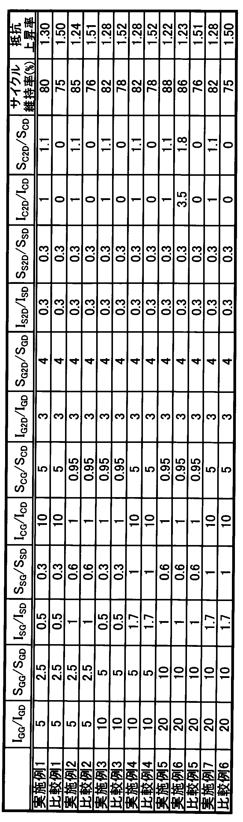
黒鉛、ケイ素酸化物およびカーボンナノチューブのGバンドとDバンドのピーク比を変化させた例について結果を表2にまとめた。
The results are shown in Table 2 for examples in which the peak ratio of G band and D band of graphite, silicon oxide and carbon nanotube was changed.

黒鉛、ケイ素酸化物およびカーボンナノチューブの2DバンドとDバンドのピーク比を変化させた例について結果を表3にまとめた。
The results are shown in Table 3 for examples in which the peak ratio between the 2D band and the D band of graphite, silicon oxide, and carbon nanotube was changed.
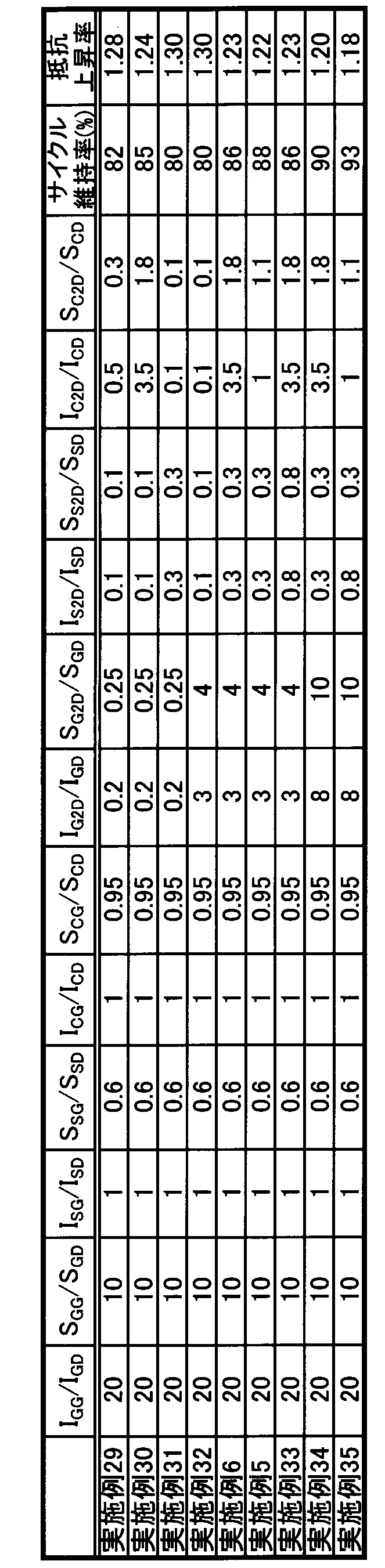
本発明によるリチウムイオン二次電池は、例えば、電源を必要とするあらゆる産業分野、ならびに電気的エネルギーの輸送、貯蔵および供給に関する産業分野において利用することができる。具体的には、携帯電話、ノートパソコン等のモバイル機器の電源;電気自動車、ハイブリッドカー、電動バイク、電動アシスト自転車等を含む電動車両、電車、衛星、潜水艦等の移動・輸送用媒体の電源;UPS等のバックアップ電源;太陽光発電、風力発電等で発電した電力を貯める蓄電設備;等に、利用することができる。
The lithium ion secondary battery according to the present invention can be used in, for example, all industrial fields that require a power source and industrial fields related to transport, storage, and supply of electrical energy. Specifically, power sources for mobile devices such as mobile phones and laptop computers; power sources for mobile vehicles such as electric vehicles, hybrid cars, electric motorcycles, electric assist bicycles, electric vehicles, trains, satellites, submarines, etc .; It can be used for backup power sources such as UPS; power storage facilities for storing power generated by solar power generation, wind power generation, etc.
10 フィルム外装体
20 電池要素
25 セパレータ
30 正極
40 負極 DESCRIPTION OFSYMBOLS 10 Film exterior 20 Battery element 25 Separator 30 Positive electrode 40 Negative electrode
20 電池要素
25 セパレータ
30 正極
40 負極 DESCRIPTION OF
Claims (11)
- ラマン分光測定により得られるラマンスペクトルにおいて2600~2800cm-1にピークを有するカーボンナノチューブと、黒鉛と、組成がSiOx(但し、0<x≦2)で表されるケイ素酸化物と、を含む負極を有するリチウムイオン二次電池。 A negative electrode comprising a carbon nanotube having a peak at 2600 to 2800 cm −1 in a Raman spectrum obtained by Raman spectroscopy, graphite, and a silicon oxide having a composition represented by SiO x (where 0 <x ≦ 2) A lithium ion secondary battery.
- ラマン分光測定により得られるラマンスペクトルにおいて1500~1700cm-1のピーク強度(IG)と1000~1400cm-1のピーク強度(ID)の比(IG/ID)を、黒鉛についてはIGG/IGDと表し、ケイ素酸化物についてはISG/ISDと表し、カーボンナノチューブについてはICG/ICDと表したとき、負極に含まれる黒鉛、ケイ素酸化物およびカーボンナノチューブのピーク強度比が以下式を満たす、請求項1に記載のリチウムイオン二次電池。
1<IGG/IGD<20
0.8<ISG/ISD<2
1<ICG/ICD<16 The ratio (I G / I D ) between the peak intensity (I G ) of 1500-1700 cm −1 and the peak intensity (I D ) of 1000-1400 cm −1 in the Raman spectrum obtained by Raman spectroscopic measurement, and I GG for graphite / I GD , silicon oxide is expressed as I SG / I SD, and carbon nanotube is expressed as I CG / I CD , when the peak intensity ratio of graphite, silicon oxide and carbon nanotube contained in the negative electrode is The lithium ion secondary battery of Claim 1 which satisfy | fills a following formula.
1 <I GG / I GD <20
0.8 <I SG / I SD <2
1 <I CG / I CD <16 - 負極に含まれる黒鉛、ケイ素酸化物およびカーボンナノチューブのピーク強度比が以下式を満たす、請求項2に記載のリチウムイオン二次電池。
10<IGG/IGD<20
0.9<ISG/ISD<1.2
1<ICG/ICD<2 The lithium ion secondary battery according to claim 2, wherein a peak intensity ratio of graphite, silicon oxide, and carbon nanotube contained in the negative electrode satisfies the following formula.
10 <I GG / I GD <20
0.9 <I SG / I SD <1.2
1 <I CG / I CD <2 - ラマン分光測定により得られるラマンスペクトルにおいて1500~1700cm-1のピーク面積(SG)と1000~1400cm-1のピーク面積(SD)の比(SG/SD)を、黒鉛についてはSGG/SGDと表し、ケイ素酸化物についてはSSG/SSDと表し、カーボンナノチューブについてはSCG/SCDと表したとき、負極に含まれる黒鉛、ケイ素酸化物およびカーボンナノチューブのピーク面積比が以下式を満たす、請求項1~3のいずれか1項に記載のリチウムイオン二次電池。
1<SGG/SGD<10
0.8<SSG/SSD<1.2
1<SCG/SCD<10 The ratio of the peak area of 1500 ~ 1700 cm -1 in the Raman spectrum obtained by Raman spectroscopy (S G) and 1000 peak area of ~ 1400cm -1 (S D) a (S G / S D), for the graphite S GG / represents a S GD, the silicon oxide expressed as S SG / S SD, when expressed as S CG / S CD for carbon nanotubes, graphite, the peak area ratio of silicon oxide and the carbon nanotubes contained in the negative electrode The lithium ion secondary battery according to any one of claims 1 to 3, wherein the following formula is satisfied.
1 <S GG / S GD <10
0.8 <S SG / S SD <1.2
1 <S CG / S CD < 10 - 負極に含まれる黒鉛、ケイ素酸化物およびカーボンナノチューブのピーク面積比が以下式を満たす、請求項4に記載のリチウムイオン二次電池。
4<SGG/SGD<10
0.9<SSG/SSD<1.2
1<SCG/SCD<2 The lithium ion secondary battery according to claim 4, wherein a peak area ratio of graphite, silicon oxide and carbon nanotube contained in the negative electrode satisfies the following formula.
4 <S GG / S GD <10
0.9 <S SG / S SD <1.2
1 <S CG / S CD < 2 - ラマン分光測定で得られるラマンスペクトルにおいて2600~2800cm-1のピーク強度(I2D)と1000~1400cm-1のピーク強度(ID)の比(I2D/ID)を、黒鉛についてはIG2D/IGDと表し、ケイ素酸化物についてはIS2D/ISDと表し、カーボンナノチューブについてはIC2D/ICDと表したとき、負極に含まれる黒鉛、ケイ素酸化物およびカーボンナノチューブのピーク強度比が以下式の少なくとも1つを満たす、請求項1~5のいずれか1項に記載のリチウムイオン二次電池。
0.5<IG2D/IGD<10
0.2<IS2D/ISD<1.0
0.8<IC2D/ICD<7 2600 ~ peak intensity of 2800 cm -1 in the Raman spectrum obtained by Raman spectroscopy a ratio of (I 2D) and 1000 peak intensity of ~ 1400cm -1 (I D) ( I 2D / I D), for the graphite I G2D / I GD , silicon oxide is expressed as I S2D / I SD, and carbon nanotube is expressed as I C2D / I CD , the peak intensity ratio of graphite, silicon oxide and carbon nanotube contained in the negative electrode is The lithium ion secondary battery according to any one of claims 1 to 5, wherein at least one of the following formulas is satisfied.
0.5 <I G2D / I GD <10
0.2 <I S2D / I SD <1.0
0.8 <I C2D / I CD <7 - 負極に含まれる黒鉛、ケイ素酸化物およびカーボンナノチューブのピーク強度比が以下式を満たす、請求項6に記載のリチウムイオン二次電池。
5<IG2D/IGD<10
0.5<IS2D/ISD<0.9
0.8<IC2D/ICD<1.2 The lithium ion secondary battery according to claim 6, wherein a peak intensity ratio of graphite, silicon oxide, and carbon nanotube contained in the negative electrode satisfies the following formula.
5 <I G2D / I GD <10
0.5 <I S2D / I SD <0.9
0.8 <I C2D / I CD <1.2 - カーボンナノチューブを負極活物質の総量に対して20質量%以下の量で負極に含む、請求項1~7のいずれか1項に記載のリチウムイオン二次電池。 The lithium ion secondary battery according to any one of claims 1 to 7, comprising carbon nanotubes in the negative electrode in an amount of 20% by mass or less based on the total amount of the negative electrode active material.
- カーボンナノチューブを負極活物質の総量に対して5質量%以下の量で負極に含む、請求項8に記載のリチウムイオン二次電池。 The lithium ion secondary battery according to claim 8, comprising carbon nanotubes in the negative electrode in an amount of 5% by mass or less based on the total amount of the negative electrode active material.
- 請求項1~9のいずれか1項に記載のリチウムイオン二次電池を搭載した車両。 A vehicle equipped with the lithium ion secondary battery according to any one of claims 1 to 9.
- 二次電池の製造方法であって、
正極と負極とをセパレータを介して積層して電極素子を製造する工程と、
前記電極素子と電解液とを外装体に封入する工程と、
を含み、
前記負極は、ラマン分光測定により得られるラマンスペクトルにおいて2600~2800cm-1にピークを有するカーボンナノチューブと、黒鉛と、組成がSiOx(但し、0<x≦2)で表されるケイ素酸化物と、を含むことを特徴とする、リチウムイオン二次電池の製造方法。 A method for manufacturing a secondary battery, comprising:
Laminating a positive electrode and a negative electrode via a separator to produce an electrode element;
Encapsulating the electrode element and the electrolyte in an exterior body;
Including
The negative electrode includes a carbon nanotube having a peak at 2600 to 2800 cm −1 in a Raman spectrum obtained by Raman spectroscopy, graphite, and a silicon oxide having a composition represented by SiO x (where 0 <x ≦ 2). The manufacturing method of a lithium ion secondary battery characterized by the above-mentioned.
Priority Applications (2)
| Application Number | Priority Date | Filing Date | Title |
|---|---|---|---|
| JP2017527507A JP6965745B2 (en) | 2015-07-09 | 2016-07-08 | Lithium ion secondary battery |
| US15/742,184 US20180198159A1 (en) | 2015-07-09 | 2016-07-08 | Lithium ion secondary battery |
Applications Claiming Priority (2)
| Application Number | Priority Date | Filing Date | Title |
|---|---|---|---|
| JP2015137887 | 2015-07-09 | ||
| JP2015-137887 | 2015-07-09 |
Publications (1)
| Publication Number | Publication Date |
|---|---|
| WO2017007013A1 true WO2017007013A1 (en) | 2017-01-12 |
Family
ID=57685654
Family Applications (1)
| Application Number | Title | Priority Date | Filing Date |
|---|---|---|---|
| PCT/JP2016/070253 WO2017007013A1 (en) | 2015-07-09 | 2016-07-08 | Lithium ion secondary battery |
Country Status (3)
| Country | Link |
|---|---|
| US (1) | US20180198159A1 (en) |
| JP (1) | JP6965745B2 (en) |
| WO (1) | WO2017007013A1 (en) |
Cited By (6)
| Publication number | Priority date | Publication date | Assignee | Title |
|---|---|---|---|---|
| CN108896524A (en) * | 2018-04-09 | 2018-11-27 | 合肥国轩高科动力能源有限公司 | A kind of large area characterization LiFePO4-amorphous carbon composite material method |
| JP2019185943A (en) * | 2018-04-05 | 2019-10-24 | トヨタ自動車株式会社 | Method for manufacturing lithium secondary battery negative electrode |
| JP2020013718A (en) * | 2018-07-19 | 2020-01-23 | トヨタ自動車株式会社 | Non-aqueous electrolyte secondary battery, evaluating method of negative electrode mixture layer, and manufacturing method of non-aqueous electrolyte secondary battery |
| CN113169326A (en) * | 2020-04-24 | 2021-07-23 | 宁德新能源科技有限公司 | Negative electrode material, pole piece containing same, electrochemical device and electronic device |
| WO2022224824A1 (en) | 2021-04-21 | 2022-10-27 | 三洋電機株式会社 | Non-aqueous electrolyte secondary battery |
| JP7466982B2 (en) | 2020-08-28 | 2024-04-15 | エルジー エナジー ソリューション リミテッド | Anode and secondary battery including said anode |
Families Citing this family (3)
| Publication number | Priority date | Publication date | Assignee | Title |
|---|---|---|---|---|
| JP7206379B2 (en) * | 2019-11-28 | 2023-01-17 | 寧徳新能源科技有限公司 | Negative electrode material and electrochemical device and electronic equipment containing the same |
| US11145580B1 (en) * | 2020-03-25 | 2021-10-12 | International Business Machines Corporation | IoT and AI system package with solid-state battery enhanced performance |
| US11239150B2 (en) | 2020-03-25 | 2022-02-01 | International Business Machines Corporation | Battery-free and substrate-free IoT and AI system package |
Citations (4)
| Publication number | Priority date | Publication date | Assignee | Title |
|---|---|---|---|---|
| JP2012033440A (en) * | 2010-08-03 | 2012-02-16 | Masstech:Kk | Silicon-based negative electrode of lithium ion battery |
| WO2012077781A1 (en) * | 2010-12-09 | 2012-06-14 | 日本電気株式会社 | Nonaqueous-electrolytic-solution secondary battery, and positive electrode and negative electrode used therefor |
| JP2012214342A (en) * | 2011-03-31 | 2012-11-08 | Nec Corp | Carbon nanotube nanohorn conjugate, and manufacturing method and use of the same |
| JP2014013671A (en) * | 2012-07-03 | 2014-01-23 | Showa Denko Kk | Composite carbon fiber |
Family Cites Families (5)
| Publication number | Priority date | Publication date | Assignee | Title |
|---|---|---|---|---|
| JP4109952B2 (en) * | 2001-10-04 | 2008-07-02 | キヤノン株式会社 | Method for producing nanocarbon material |
| KR101211949B1 (en) * | 2010-11-17 | 2012-12-18 | 성균관대학교산학협력단 | Hybrid complex and Method of preparing thereof |
| JP2014169193A (en) * | 2013-03-01 | 2014-09-18 | Nec Corp | Carbon material composed of nanocarbon and graphene or graphite compounded with each other, and method for producing the same |
| US20160293956A1 (en) * | 2013-11-05 | 2016-10-06 | The Regents Of The University Of California | Hybrid carbon nanotube and graphene nanostructures |
| EP3093910B1 (en) * | 2014-01-09 | 2019-06-19 | Showa Denko K.K. | Negative electrode active material for lithium-ion secondary cell |
-
2016
- 2016-07-08 JP JP2017527507A patent/JP6965745B2/en active Active
- 2016-07-08 WO PCT/JP2016/070253 patent/WO2017007013A1/en active Application Filing
- 2016-07-08 US US15/742,184 patent/US20180198159A1/en not_active Abandoned
Patent Citations (4)
| Publication number | Priority date | Publication date | Assignee | Title |
|---|---|---|---|---|
| JP2012033440A (en) * | 2010-08-03 | 2012-02-16 | Masstech:Kk | Silicon-based negative electrode of lithium ion battery |
| WO2012077781A1 (en) * | 2010-12-09 | 2012-06-14 | 日本電気株式会社 | Nonaqueous-electrolytic-solution secondary battery, and positive electrode and negative electrode used therefor |
| JP2012214342A (en) * | 2011-03-31 | 2012-11-08 | Nec Corp | Carbon nanotube nanohorn conjugate, and manufacturing method and use of the same |
| JP2014013671A (en) * | 2012-07-03 | 2014-01-23 | Showa Denko Kk | Composite carbon fiber |
Cited By (13)
| Publication number | Priority date | Publication date | Assignee | Title |
|---|---|---|---|---|
| JP2019185943A (en) * | 2018-04-05 | 2019-10-24 | トヨタ自動車株式会社 | Method for manufacturing lithium secondary battery negative electrode |
| CN108896524B (en) * | 2018-04-09 | 2021-02-26 | 合肥国轩高科动力能源有限公司 | Method for large-area characterization of lithium iron phosphate-amorphous carbon composite material |
| CN108896524A (en) * | 2018-04-09 | 2018-11-27 | 合肥国轩高科动力能源有限公司 | A kind of large area characterization LiFePO4-amorphous carbon composite material method |
| US11011744B2 (en) | 2018-07-19 | 2021-05-18 | Toyota Jidosha Kabushiki Kaisha | Non-aqueous electrolyte secondary battery, method of evaluating negative electrode composite material layer, and method of producing non-aqueous electrolyte secondary battery |
| KR20200010063A (en) * | 2018-07-19 | 2020-01-30 | 도요타지도샤가부시키가이샤 | Non-aqueous electrolyte secondary battery, method of evaluating negative electrode composite material layer, and method of producing non-aqueous electrolyte secondary battery |
| KR102239060B1 (en) | 2018-07-19 | 2021-04-12 | 도요타지도샤가부시키가이샤 | Non-aqueous electrolyte secondary battery, method of evaluating negative electrode composite material layer, and method of producing non-aqueous electrolyte secondary battery |
| JP2020013718A (en) * | 2018-07-19 | 2020-01-23 | トヨタ自動車株式会社 | Non-aqueous electrolyte secondary battery, evaluating method of negative electrode mixture layer, and manufacturing method of non-aqueous electrolyte secondary battery |
| CN113169326A (en) * | 2020-04-24 | 2021-07-23 | 宁德新能源科技有限公司 | Negative electrode material, pole piece containing same, electrochemical device and electronic device |
| WO2021212455A1 (en) * | 2020-04-24 | 2021-10-28 | 宁德新能源科技有限公司 | Negative electrode material, pole containing material, electrochemical apparatus and electronic apparatus |
| JP2022533283A (en) * | 2020-04-24 | 2022-07-22 | 寧徳新能源科技有限公司 | Anode materials, pole pieces containing such materials, electrochemical devices and electronic devices |
| JP7360462B2 (en) | 2020-04-24 | 2023-10-12 | 寧徳新能源科技有限公司 | Negative electrode materials, pole pieces containing the materials, electrochemical devices, and electronic devices |
| JP7466982B2 (en) | 2020-08-28 | 2024-04-15 | エルジー エナジー ソリューション リミテッド | Anode and secondary battery including said anode |
| WO2022224824A1 (en) | 2021-04-21 | 2022-10-27 | 三洋電機株式会社 | Non-aqueous electrolyte secondary battery |
Also Published As
| Publication number | Publication date |
|---|---|
| JPWO2017007013A1 (en) | 2018-04-19 |
| JP6965745B2 (en) | 2021-11-10 |
| US20180198159A1 (en) | 2018-07-12 |
Similar Documents
| Publication | Publication Date | Title |
|---|---|---|
| US10629890B2 (en) | Negative electrode material for non-aqueous electrolyte secondary battery, negative electrode for non-aqueous electrolyte secondary battery, non-aqueous electrolyte secondary battery, and method of producing negative electrode active material particles | |
| JP6965745B2 (en) | Lithium ion secondary battery | |
| JP6848435B2 (en) | Lithium ion secondary battery | |
| US11322773B2 (en) | Lithium secondary battery | |
| US10714751B2 (en) | Negative electrode for lithium ion secondary battery and lithium ion secondary battery | |
| US11362318B2 (en) | Lithium ion secondary battery | |
| US10608244B2 (en) | Lithium ion secondary battery | |
| WO2016152876A1 (en) | Lithium-ion secondary cell and method for manufacturing same | |
| US10777817B2 (en) | Lithium ion secondary battery | |
| WO2015152114A1 (en) | Graphite-based active material, negative electrode, and negative ion secondary cell | |
| JP5855737B2 (en) | Lithium ion battery | |
| WO2016093246A1 (en) | Lithium ion secondary battery | |
| JP6812966B2 (en) | Negative electrode and secondary battery for lithium ion secondary battery | |
| JP6809449B2 (en) | Lithium ion secondary battery | |
| WO2019088171A1 (en) | Lithium ion secondary battery | |
| WO2017094719A1 (en) | Lithium ion secondary battery | |
| JP2023144412A (en) | Negative electrode and secondary battery with the same |
Legal Events
| Date | Code | Title | Description |
|---|---|---|---|
| 121 | Ep: the epo has been informed by wipo that ep was designated in this application |
Ref document number: 16821481 Country of ref document: EP Kind code of ref document: A1 |
|
| ENP | Entry into the national phase |
Ref document number: 2017527507 Country of ref document: JP Kind code of ref document: A |
|
| NENP | Non-entry into the national phase |
Ref country code: DE |
|
| 122 | Ep: pct application non-entry in european phase |
Ref document number: 16821481 Country of ref document: EP Kind code of ref document: A1 |