WO2017006480A1 - Nonaqueous electrolyte secondary battery - Google Patents
Nonaqueous electrolyte secondary battery Download PDFInfo
- Publication number
- WO2017006480A1 WO2017006480A1 PCT/JP2015/069771 JP2015069771W WO2017006480A1 WO 2017006480 A1 WO2017006480 A1 WO 2017006480A1 JP 2015069771 W JP2015069771 W JP 2015069771W WO 2017006480 A1 WO2017006480 A1 WO 2017006480A1
- Authority
- WO
- WIPO (PCT)
- Prior art keywords
- additive
- electrolyte
- active material
- negative electrode
- secondary battery
- Prior art date
Links
Images


Classifications
-
- H—ELECTRICITY
- H01—ELECTRIC ELEMENTS
- H01M—PROCESSES OR MEANS, e.g. BATTERIES, FOR THE DIRECT CONVERSION OF CHEMICAL ENERGY INTO ELECTRICAL ENERGY
- H01M10/00—Secondary cells; Manufacture thereof
- H01M10/05—Accumulators with non-aqueous electrolyte
- H01M10/056—Accumulators with non-aqueous electrolyte characterised by the materials used as electrolytes, e.g. mixed inorganic/organic electrolytes
- H01M10/0564—Accumulators with non-aqueous electrolyte characterised by the materials used as electrolytes, e.g. mixed inorganic/organic electrolytes the electrolyte being constituted of organic materials only
- H01M10/0566—Liquid materials
- H01M10/0567—Liquid materials characterised by the additives
-
- H—ELECTRICITY
- H01—ELECTRIC ELEMENTS
- H01M—PROCESSES OR MEANS, e.g. BATTERIES, FOR THE DIRECT CONVERSION OF CHEMICAL ENERGY INTO ELECTRICAL ENERGY
- H01M10/00—Secondary cells; Manufacture thereof
- H01M10/05—Accumulators with non-aqueous electrolyte
- H01M10/056—Accumulators with non-aqueous electrolyte characterised by the materials used as electrolytes, e.g. mixed inorganic/organic electrolytes
- H01M10/0561—Accumulators with non-aqueous electrolyte characterised by the materials used as electrolytes, e.g. mixed inorganic/organic electrolytes the electrolyte being constituted of inorganic materials only
- H01M10/0562—Solid materials
-
- H—ELECTRICITY
- H01—ELECTRIC ELEMENTS
- H01M—PROCESSES OR MEANS, e.g. BATTERIES, FOR THE DIRECT CONVERSION OF CHEMICAL ENERGY INTO ELECTRICAL ENERGY
- H01M10/00—Secondary cells; Manufacture thereof
- H01M10/05—Accumulators with non-aqueous electrolyte
- H01M10/052—Li-accumulators
-
- H—ELECTRICITY
- H01—ELECTRIC ELEMENTS
- H01M—PROCESSES OR MEANS, e.g. BATTERIES, FOR THE DIRECT CONVERSION OF CHEMICAL ENERGY INTO ELECTRICAL ENERGY
- H01M10/00—Secondary cells; Manufacture thereof
- H01M10/05—Accumulators with non-aqueous electrolyte
- H01M10/052—Li-accumulators
- H01M10/0525—Rocking-chair batteries, i.e. batteries with lithium insertion or intercalation in both electrodes; Lithium-ion batteries
-
- H—ELECTRICITY
- H01—ELECTRIC ELEMENTS
- H01M—PROCESSES OR MEANS, e.g. BATTERIES, FOR THE DIRECT CONVERSION OF CHEMICAL ENERGY INTO ELECTRICAL ENERGY
- H01M10/00—Secondary cells; Manufacture thereof
- H01M10/05—Accumulators with non-aqueous electrolyte
- H01M10/056—Accumulators with non-aqueous electrolyte characterised by the materials used as electrolytes, e.g. mixed inorganic/organic electrolytes
- H01M10/0564—Accumulators with non-aqueous electrolyte characterised by the materials used as electrolytes, e.g. mixed inorganic/organic electrolytes the electrolyte being constituted of organic materials only
- H01M10/0566—Liquid materials
- H01M10/0568—Liquid materials characterised by the solutes
-
- H—ELECTRICITY
- H01—ELECTRIC ELEMENTS
- H01M—PROCESSES OR MEANS, e.g. BATTERIES, FOR THE DIRECT CONVERSION OF CHEMICAL ENERGY INTO ELECTRICAL ENERGY
- H01M50/00—Constructional details or processes of manufacture of the non-active parts of electrochemical cells other than fuel cells, e.g. hybrid cells
- H01M50/40—Separators; Membranes; Diaphragms; Spacing elements inside cells
- H01M50/409—Separators, membranes or diaphragms characterised by the material
- H01M50/44—Fibrous material
-
- H—ELECTRICITY
- H01—ELECTRIC ELEMENTS
- H01M—PROCESSES OR MEANS, e.g. BATTERIES, FOR THE DIRECT CONVERSION OF CHEMICAL ENERGY INTO ELECTRICAL ENERGY
- H01M4/00—Electrodes
- H01M4/02—Electrodes composed of, or comprising, active material
- H01M2004/026—Electrodes composed of, or comprising, active material characterised by the polarity
- H01M2004/027—Negative electrodes
-
- H—ELECTRICITY
- H01—ELECTRIC ELEMENTS
- H01M—PROCESSES OR MEANS, e.g. BATTERIES, FOR THE DIRECT CONVERSION OF CHEMICAL ENERGY INTO ELECTRICAL ENERGY
- H01M4/00—Electrodes
- H01M4/02—Electrodes composed of, or comprising, active material
- H01M2004/026—Electrodes composed of, or comprising, active material characterised by the polarity
- H01M2004/028—Positive electrodes
-
- H—ELECTRICITY
- H01—ELECTRIC ELEMENTS
- H01M—PROCESSES OR MEANS, e.g. BATTERIES, FOR THE DIRECT CONVERSION OF CHEMICAL ENERGY INTO ELECTRICAL ENERGY
- H01M2300/00—Electrolytes
- H01M2300/0017—Non-aqueous electrolytes
- H01M2300/0025—Organic electrolyte
-
- H—ELECTRICITY
- H01—ELECTRIC ELEMENTS
- H01M—PROCESSES OR MEANS, e.g. BATTERIES, FOR THE DIRECT CONVERSION OF CHEMICAL ENERGY INTO ELECTRICAL ENERGY
- H01M50/00—Constructional details or processes of manufacture of the non-active parts of electrochemical cells other than fuel cells, e.g. hybrid cells
- H01M50/10—Primary casings, jackets or wrappings of a single cell or a single battery
- H01M50/102—Primary casings, jackets or wrappings of a single cell or a single battery characterised by their shape or physical structure
- H01M50/105—Pouches or flexible bags
-
- H—ELECTRICITY
- H01—ELECTRIC ELEMENTS
- H01M—PROCESSES OR MEANS, e.g. BATTERIES, FOR THE DIRECT CONVERSION OF CHEMICAL ENERGY INTO ELECTRICAL ENERGY
- H01M50/00—Constructional details or processes of manufacture of the non-active parts of electrochemical cells other than fuel cells, e.g. hybrid cells
- H01M50/40—Separators; Membranes; Diaphragms; Spacing elements inside cells
- H01M50/409—Separators, membranes or diaphragms characterised by the material
- H01M50/431—Inorganic material
- H01M50/434—Ceramics
- H01M50/437—Glass
-
- H—ELECTRICITY
- H01—ELECTRIC ELEMENTS
- H01M—PROCESSES OR MEANS, e.g. BATTERIES, FOR THE DIRECT CONVERSION OF CHEMICAL ENERGY INTO ELECTRICAL ENERGY
- H01M50/00—Constructional details or processes of manufacture of the non-active parts of electrochemical cells other than fuel cells, e.g. hybrid cells
- H01M50/40—Separators; Membranes; Diaphragms; Spacing elements inside cells
- H01M50/463—Separators, membranes or diaphragms characterised by their shape
-
- H—ELECTRICITY
- H01—ELECTRIC ELEMENTS
- H01M—PROCESSES OR MEANS, e.g. BATTERIES, FOR THE DIRECT CONVERSION OF CHEMICAL ENERGY INTO ELECTRICAL ENERGY
- H01M50/00—Constructional details or processes of manufacture of the non-active parts of electrochemical cells other than fuel cells, e.g. hybrid cells
- H01M50/40—Separators; Membranes; Diaphragms; Spacing elements inside cells
- H01M50/489—Separators, membranes, diaphragms or spacing elements inside the cells, characterised by their physical properties, e.g. swelling degree, hydrophilicity or shut down properties
-
- Y—GENERAL TAGGING OF NEW TECHNOLOGICAL DEVELOPMENTS; GENERAL TAGGING OF CROSS-SECTIONAL TECHNOLOGIES SPANNING OVER SEVERAL SECTIONS OF THE IPC; TECHNICAL SUBJECTS COVERED BY FORMER USPC CROSS-REFERENCE ART COLLECTIONS [XRACs] AND DIGESTS
- Y02—TECHNOLOGIES OR APPLICATIONS FOR MITIGATION OR ADAPTATION AGAINST CLIMATE CHANGE
- Y02E—REDUCTION OF GREENHOUSE GAS [GHG] EMISSIONS, RELATED TO ENERGY GENERATION, TRANSMISSION OR DISTRIBUTION
- Y02E60/00—Enabling technologies; Technologies with a potential or indirect contribution to GHG emissions mitigation
- Y02E60/10—Energy storage using batteries
-
- Y—GENERAL TAGGING OF NEW TECHNOLOGICAL DEVELOPMENTS; GENERAL TAGGING OF CROSS-SECTIONAL TECHNOLOGIES SPANNING OVER SEVERAL SECTIONS OF THE IPC; TECHNICAL SUBJECTS COVERED BY FORMER USPC CROSS-REFERENCE ART COLLECTIONS [XRACs] AND DIGESTS
- Y02—TECHNOLOGIES OR APPLICATIONS FOR MITIGATION OR ADAPTATION AGAINST CLIMATE CHANGE
- Y02T—CLIMATE CHANGE MITIGATION TECHNOLOGIES RELATED TO TRANSPORTATION
- Y02T10/00—Road transport of goods or passengers
- Y02T10/60—Other road transportation technologies with climate change mitigation effect
- Y02T10/70—Energy storage systems for electromobility, e.g. batteries
Definitions
- the present invention relates to a non-aqueous electrolyte secondary battery.
- Nonaqueous electrolyte secondary batteries especially lithium ion secondary batteries, have been widely used as power supplies for mobile devices due to their high energy density, high durability, charge / discharge efficiency, and the like.
- lithium ion secondary batteries have been used for large system power supplies such as electric vehicles and stationary power storage systems. Batteries used for these power sources are required to improve battery characteristics such as battery enlargement, further increase in energy density, and high production efficiency for economically establishing the battery performance.
- the nonaqueous solvent in the electrolyte decomposes by electrochemically reacting with the negative electrode active material, and the decomposition product generated at that time is the surface of the negative electrode active material.
- SEI Solid-Electrolyte-Interface
- the reaction resistance of the electrode increases.
- the SEI film deposited in this way is usually a rigid inorganic film, it is destroyed by stress caused by expansion and contraction of the negative electrode active material during charge and discharge, and the electrode characteristics deteriorate. There is also.
- an additive is added to the electrolyte of the lithium ion secondary battery.
- the decomposition product can be newly decomposed. Functions as a protective SEI film to suppress. It is known that the SEI film with such an additive greatly affects the cycle performance, storage performance, charge / discharge efficiency, and safety of the battery.
- the present invention is a non-aqueous electrolyte secondary battery such as a lithium ion secondary battery, and is hardly affected by specifications such as active materials used to constitute the battery, and the durability of the battery (cycle durability, It is an object of the present invention to provide means capable of improving both storage durability and input / output characteristics (cell internal resistance).
- the present inventors have accumulated earnest research. As a result, a liquid electrolyte containing a plurality of additives selected from a predetermined compound is used, and the addition amount of each of the plurality of additives and the BET specific surface area of the negative electrode active material satisfy a predetermined relational expression. It has been found that the above-mentioned problems can be solved by controlling to the above, and the present invention has been completed.
- a positive electrode in which a positive electrode active material layer containing a positive electrode active material is formed on the surface of a positive electrode current collector, and a negative electrode active material containing a negative electrode active material on the surface of the negative electrode current collector
- a nonaqueous electrolyte secondary battery having a power generation element including a negative electrode formed with a layer and a separator containing an electrolyte.
- the electrolyte is an electrolyte salt, a non-aqueous solvent capable of dissolving the electrolyte salt, the first additive, and a reduction potential lower than the reduction potential of the first additive.
- the first additive and the second additive are selected from predetermined compounds, and the negative electrode active material has a BET specific surface area of SSA [m 2 / g
- the ratio of the electrolytic mass to the total pore volume (liquid coefficient) of the positive electrode, the negative electrode, and the separator is L, and the total amount of the nonaqueous solvent and the electrolyte salt in the amount of the first additive added to the electrolyte
- a [mass%] and the ratio of the amount of the second additive added to the electrolyte with respect to the total amount of the nonaqueous solvent and the electrolyte salt is B [mass%], 0.21 ⁇ A ⁇ L / SSA ⁇ 0.69 and 0.51 ⁇ B ⁇ L / SSA ⁇ 1.5 It is characterized by satisfying.
- FIG. 3 is a schematic cross-sectional view schematically showing the outline of a nonaqueous electrolyte secondary battery which is an embodiment of the battery of the present invention, and is a schematic cross-sectional view taken along the line AA shown in FIG. 2 to be described later. It is a perspective view showing the appearance of a flat nonaqueous electrolyte secondary battery which is a typical embodiment of the battery of the present invention.
- a positive electrode in which a positive electrode active material layer containing a positive electrode active material is formed on the surface of a positive electrode current collector, and a negative electrode active material layer containing a negative electrode active material on the surface of the negative electrode current collector are provided.
- a power generation element including a formed negative electrode and a separator containing an electrolyte, wherein the electrolyte is an electrolyte salt, a non-aqueous solvent capable of dissolving the electrolyte salt, a first additive, and the first addition
- a second additive having a lower reduction potential than the reduction potential of the agent, wherein the first additive includes an oxalate compound represented by a predetermined chemical formula and a disulfonic acid represented by a predetermined chemical formula And at least one selected from the group consisting of ester compounds, and the second additive is vinylene carbonate, fluoroethylene carbonate, vinylethylene carbonate, 1,3-propane sultone, 1,4 Butane sultone, 1,3-propene sultone, comprises at least one member selected from the group consisting of succinonitrile, and adiponitrile, a BET specific surface area of the negative active material and SSA [m 2 / g], the positive electrode, negative electrode and The ratio (liquid coefficient
- the SEI film by the first additive capable of forming a compact and dense SEI film is made active in the negative electrode. It can be sufficiently and uniformly formed on the surface of the substance. As a result, the storage durability of the battery can be improved.
- the SEI film having a laminated structure of the first additive and the second additive can be stabilized on the surface of the negative electrode active material. Can be formed. As a result, the cycle durability of the battery can be improved.
- FIG. 1 is a schematic cross-sectional view schematically showing an outline of a non-aqueous electrolyte secondary battery (hereinafter also simply referred to as “stacked battery”) which is an embodiment of the battery of the present invention.
- FIG. 2 is a schematic cross-sectional view along the line AA shown in FIG.
- the flat type (stacked type) lithium ion secondary battery shown in FIG. 1 will be described in detail as an example, but the technical scope of the present invention is only such a form. Not limited to.
- the stacked battery 10 of the present embodiment has a structure in which a substantially rectangular power generation element 21 in which a charge / discharge reaction actually proceeds is sealed inside a battery exterior material 29 that is an exterior body.
- the power generation element 21 has a configuration in which a positive electrode, a separator 17, and a negative electrode are stacked.
- the separator 17 contains an electrolyte (in this embodiment, a liquid electrolyte (electrolytic solution) containing an additive).
- the positive electrode has a structure in which the positive electrode active material layers 15 are disposed on both surfaces of the positive electrode current collector 12.
- the negative electrode has a structure in which the negative electrode active material layer 13 is disposed on both surfaces of the negative electrode current collector 11.
- the negative electrode, the electrolyte layer, and the positive electrode are laminated in this order so that one positive electrode active material layer 15 and the negative electrode active material layer 13 adjacent thereto face each other with a separator 17 therebetween.
- the adjacent positive electrode, electrolyte layer, and negative electrode constitute one unit cell layer 19. Therefore, it can be said that the stacked battery 10 shown in FIG. 1 has a configuration in which a plurality of single battery layers 19 are stacked and electrically connected in parallel.
- the negative electrode active material layer 13 is arrange
- the positive electrode current collector 12 and the negative electrode current collector 11 are each provided with a positive electrode current collector plate (tab) 27 and a negative electrode current collector plate (tab) 25 that are electrically connected to the respective electrodes (positive electrode and negative electrode). It has the structure led out of the battery exterior material 29 so that it may be pinched
- the positive electrode current collector 27 and the negative electrode current collector 25 are ultrasonically welded to the positive electrode current collector 12 and the negative electrode current collector 11 of each electrode, respectively, via a positive electrode lead and a negative electrode lead (not shown) as necessary. Or resistance welding or the like.
- FIG. 1 shows a flat battery (stacked battery) that is not a bipolar battery, but a positive electrode active material layer that is electrically coupled to one surface of the current collector and the opposite side of the current collector.
- a bipolar battery including a bipolar electrode having a negative electrode active material layer electrically coupled to the surface.
- one current collector also serves as a positive electrode current collector and a negative electrode current collector.
- the positive electrode has a positive electrode current collector and a positive electrode active material layer formed on the surface of the positive electrode current collector.
- a metal is preferably used.
- the metal include aluminum, nickel, iron, stainless steel, titanium, copper, and other alloys.
- a clad material of nickel and aluminum, a clad material of copper and aluminum, or a plating material of a combination of these metals can be preferably used.
- covered on the metal surface may be sufficient.
- aluminum, stainless steel, and copper are preferable from the viewpoints of electronic conductivity and battery operating potential.
- the size of the current collector is determined according to the intended use of the battery. For example, if it is used for a large battery that requires a high energy density, a current collector having a large area is used. There is no particular limitation on the thickness of the current collector.
- the thickness of the current collector is usually about 1 to 100 ⁇ m.
- the positive electrode active material layer includes a positive electrode active material.
- a positive electrode active material There is no restriction
- the positive electrode active material preferably contains a spinel-based lithium manganese composite oxide and / or a lithium-nickel composite oxide.
- preferred forms of these positive electrode active materials will be described.
- Spinel-based lithium manganese composite oxide is a composite oxide that typically has a composition of LiMn 2 O 4 and has a spinel structure and essentially contains lithium and manganese. Conventionally known knowledge can be appropriately referred to for the specific configuration and manufacturing method.
- Spinel-based lithium manganese composite oxide has a structure of secondary particles formed by agglomerating primary particles.
- the average particle size (average secondary particle size; D50) of the secondary particles is preferably 5 to 50 ⁇ m, more preferably 7 to 20 ⁇ m.
- the average secondary particle diameter is measured by a laser diffraction method.
- lithium nickel complex oxide is not specifically limited as long as it is a complex oxide containing lithium and nickel.
- a typical example of a composite oxide containing lithium and nickel is lithium nickel composite oxide (LiNiO 2 ).
- a composite oxide in which some of the nickel atoms of the lithium nickel composite oxide are substituted with other metal atoms is more preferable.
- NMC composite lithium-nickel-manganese-cobalt composite oxide
- oxide (Also referred to as “oxide”) has a layered crystal structure in which a lithium atomic layer and a transition metal (Mn, Ni, and Co are arranged in order) are alternately stacked via an oxygen atomic layer.
- a lithium atomic layer Li atomic layer
- a transition metal Mn, Ni, and Co are arranged in order
- One Li atom is contained per atom, and the amount of Li that can be taken out is twice that of the spinel-type lithium manganese oxide, that is, the supply capacity is doubled, so that a high capacity can be obtained.
- LiNiO 2 since it has higher thermal stability than LiNiO 2 , it is particularly advantageous among the nickel-based composite oxides used as the positive electrode active material.
- the NMC composite oxide includes a composite oxide in which a part of the transition metal element is substituted with another metal element.
- Other elements in that case include Ti, Zr, Nb, W, P, Al, Mg, V, Ca, Sr, Cr, Fe, B, Ga, In, Si, Mo, Y, Sn, V, Cu , Ag, Zn, etc., preferably Ti, Zr, Nb, W, P, Al, Mg, V, Ca, Sr, Cr, more preferably Ti, Zr, P, Al, Mg, From the viewpoint of improving cycle characteristics, Ti, Zr, Al, Mg, and Cr are more preferable.
- a represents the atomic ratio of Li
- b represents the atomic ratio of Ni
- c represents the atomic ratio of Mn
- d represents the atomic ratio of Co
- x represents the atomic ratio of M. Represents. From the viewpoint of cycle characteristics, it is preferable that 0.4 ⁇ b ⁇ 0.6 in the general formula (1).
- the composition of each element can be measured by, for example, inductively coupled plasma (ICP) emission spectrometry.
- ICP inductively coupled plasma
- Ni nickel
- Co cobalt
- Mn manganese
- Ti or the like partially replaces the transition metal in the crystal lattice. From the viewpoint of cycle characteristics, it is preferable that a part of the transition element is substituted with another metal element, and it is particularly preferable that 0 ⁇ x ⁇ 0.3 in the general formula (1). Since at least one selected from the group consisting of Ti, Zr, Nb, W, P, Al, Mg, V, Ca, Sr, and Cr is dissolved, the crystal structure is stabilized. It is considered that the battery capacity can be prevented from decreasing even if the above is repeated, and that excellent cycle characteristics can be realized.
- the present inventors charge and discharge the above-mentioned charge and discharge when the metal composition of nickel, manganese and cobalt is not uniform, for example, LiNi 0.5 Mn 0.3 Co 0.2 O 2. It has been found that the influence of strain / cracking of the complex oxide at the time increases. This is presumably because the stress applied to the inside of the particles during expansion and contraction is distorted and cracks are more likely to occur in the composite oxide due to the non-uniform metal composition. Therefore, for example, a complex oxide having a rich Ni abundance ratio (for example, LiNi 0.8 Mn 0.1 Co 0.1 O 2 ) or a complex oxide having a uniform ratio of Ni, Mn, and Co.
- a complex oxide having a rich Ni abundance ratio for example, LiNi 0.8 Mn 0.1 Co 0.1 O 2
- a complex oxide having a uniform ratio of Ni, Mn, and Co for example, LiNi 0.8 Mn 0.1 Co 0.1 O 2
- composite oxides in which b, c and d are 0.44 ⁇ b ⁇ 0.51, 0.27 ⁇ c ⁇ 0.31, 0.19 ⁇ d ⁇ 0.26 The positive electrode active material is preferable. By adopting such a configuration, a battery having an excellent balance between capacity characteristics and output characteristics can be provided.
- the lithium nickel composite oxide also has a secondary particle structure in which primary particles are aggregated.
- the average primary particle size (average primary particle size; D50) is preferably 0.9 ⁇ m or less, more preferably 0.20 to 0.6 ⁇ m, and even more preferably 0.25 to 0.5 ⁇ m. It is.
- the average particle diameter of the secondary particles (average secondary particle diameter; D50) is preferably 5 to 20 ⁇ m, more preferably 5 to 15 ⁇ m.
- the value of these ratios (average secondary particle size / average primary particle size) is preferably greater than 11, more preferably 15 to 50, and even more preferably 25 to 40.
- the primary particles constituting the lithium nickel composite oxide usually have a hexagonal crystal structure having a layered structure, but the size of the crystallite is correlated with the size of the average primary particle size.
- crystallite means the largest group that can be regarded as a single crystal, and can be measured by a method of refining the crystal structure parameters from the diffraction intensity obtained by powder X-ray diffraction measurement or the like.
- the specific value of the crystallite size of the primary particles constituting the lithium nickel composite oxide is not particularly limited, but from the viewpoint of life characteristics, it is preferably 1 ⁇ m or less, more preferably 360 nm or less, Preferably it is 310 nm or less.
- the value of the crystallite diameter in the positive electrode active material particles is measured by the Rietveld method in which the crystallite diameter is calculated from the diffraction peak intensity obtained by powder X-ray diffraction measurement.
- the tap density of the lithium nickel composite oxide is preferably 2.3 g / cm 3 , more preferably 2.4 to 2.9 g / cm 3 .
- the BET specific surface area of the lithium nickel composite oxide is preferably 0.1 to 1.0 m 2 / g, more preferably 0.3 to 1.0 m 2 / g, and particularly preferably 0.00. 3 to 0.7 m 2 / g.
- the specific surface area of the active material is in such a range, the reaction area of the active material is ensured and the internal resistance of the battery is reduced, so that the occurrence of polarization during the electrode reaction can be minimized.
- the diffraction peak intensity ratio ((003) / (104)) is the diffraction peak on the (104) plane and the diffraction peak on the (003) plane obtained by powder X-ray diffraction measurement. It is preferably 1.28 or more, more preferably 1.35 to 2.1.
- the diffraction peak integrated intensity ratio ((003) / (104)) is preferably 1.08 or more, more preferably 1.10 to 1.45.
- Ni 3+ is easily reduced to Ni 2+, and because substantially equal to the Ni 2+ ion radius (0.83 ⁇ ) is Li + ion radius (0.90 ⁇ ), Ni to Li + defect occurring during active material synthesized 2+ tends to be mixed.
- Ni 2+ is mixed into the Li + site, a locally electrochemically inactive structure is formed and Li + diffusion is prevented. For this reason, when an active material with low crystallinity is used, there is a possibility that the battery charge / discharge capacity is reduced and the durability is lowered.
- the above definition is used as an index of the crystallinity.
- the ratio of the intensity of diffraction peaks of the (003) plane and the (104) plane and the ratio of the integrated intensity of the diffraction peaks by crystal structure analysis using X-ray diffraction. was used.
- these parameters satisfy the above-mentioned rules, defects in the crystal are reduced, and a decrease in battery charge / discharge capacity and a decrease in durability can be suppressed.
- Such crystallinity parameters can be controlled by the raw material, composition, firing conditions, and the like.
- the lithium nickel composite oxide such as NMC composite oxide can be prepared by selecting various known methods such as coprecipitation method and spray drying method.
- the coprecipitation method is preferably used because the complex oxide according to this embodiment is easy to prepare.
- a nickel-cobalt-manganese composite oxide is manufactured by a coprecipitation method as in the method described in JP2011-105588A, and then nickel-cobalt. It can be obtained by mixing and firing a manganese composite oxide and a lithium compound.
- the positive electrode active material includes a spinel-based lithium manganese composite oxide and a lithium-nickel-based composite oxide
- the mixing ratio thereof is not particularly limited, but from the viewpoint of life characteristics and cost, the spinel-based lithium manganese composite oxide
- the content is preferably 15 to 40% by mass and more preferably 30 to 40% by mass with respect to 100% by mass of the lithium nickel composite oxide.
- the positive electrode active material layer includes a conductive aid, a binder, an electrolyte (polymer matrix, ion conductive polymer, electrolytic solution, etc.), and a lithium salt for increasing ion conductivity, as necessary. It further contains other additives.
- the content of a material that can function as an active material in the positive electrode active material layer and the negative electrode active material layer described later is preferably 85 to 99.5% by mass.
- the conductive assistant refers to an additive that is blended in order to improve the conductivity of the positive electrode active material layer or the negative electrode active material layer.
- the conductive aid include carbon materials such as carbon black such as ketjen black and acetylene black, and carbon fibers.
- binder Although it does not specifically limit as a binder used for a positive electrode active material layer, for example, the following materials are mentioned. Polyethylene, polypropylene, polyethylene terephthalate (PET), polyether nitrile, polyacrylonitrile, polyimide, polyamide, cellulose, carboxymethyl cellulose (CMC) and its salts, ethylene-vinyl acetate copolymer, polyvinyl chloride, styrene-butadiene rubber (SBR) ), Isoprene rubber, butadiene rubber, ethylene / propylene rubber, ethylene / propylene / diene copolymer, styrene / butadiene / styrene block copolymer and hydrogenated product thereof, styrene / isoprene / styrene block copolymer and hydrogenated product thereof.
- Thermoplastic polymers such as products, polyvinylidene fluoride (P
- electrolyte salt LiPF 6, LiBF 4, LiClO 4, LiAsF 6, LiTaF 6, LiSbF 6, LiAlCl 4, Li 2 B 10 Cl 10, LiI, LiBr, LiCl, LiAlCl, LiHF 2, LiSCN , etc.
- Inorganic acid anion salt LiCF 3 SO 3 , Li (CF 3 SO 2 ) 2 N, LiBOB (lithium bisoxide borate), LiBETI (lithium bis (perfluoroethylenesulfonylimide); Li (C 2 F 5 SO 2) ) such as 2 N with described) organic acid anion salts, and the like.
- These electrolyte salts may be used alone or in the form of a mixture of two or more.
- Examples of the ion conductive polymer include polyethylene oxide (PEO) and polypropylene oxide (PPO) polymers.
- the compounding ratio of the components contained in the positive electrode active material layer and the negative electrode active material layer described later is not particularly limited.
- the blending ratio can be adjusted by appropriately referring to known knowledge about lithium ion secondary batteries.
- the thickness of each active material layer is not particularly limited, and conventionally known knowledge about the battery can be appropriately referred to. As an example, the thickness of each active material layer is about 2 to 100 ⁇ m.
- the negative electrode active material layer contains an active material, and other additives such as a conductive additive, a binder, an electrolyte (polymer matrix, ion conductive polymer, electrolyte, etc.), and a lithium salt to enhance ionic conductivity as necessary.
- a conductive additive such as a conductive additive, a binder, an electrolyte (polymer matrix, ion conductive polymer, electrolyte, etc.), and a lithium salt to enhance ionic conductivity as necessary.
- An agent is further included.
- Other additives such as conductive assistants, binders, electrolytes (polymer matrix, ion conductive polymers, electrolytes, etc.) and lithium salts for improving ion conductivity are those described in the above positive electrode active material layer column. It is the same.
- the negative electrode active material examples include carbon materials such as graphite, soft carbon, and hard carbon, lithium-transition metal composite oxides (eg, Li 4 Ti 5 O 12 ), metal materials, lithium alloy negative electrode materials, and the like. . In some cases, two or more negative electrode active materials may be used in combination. Preferably, from the viewpoint of capacity and output characteristics, a carbon material or a lithium-transition metal composite oxide (in particular, a carbon material, particularly preferably graphite) is used as the negative electrode active material. Of course, negative electrode active materials other than those described above may be used.
- the average particle diameter of the negative electrode active material is not particularly limited, but is preferably 1 to 100 ⁇ m, more preferably 1 to 20 ⁇ m from the viewpoint of increasing the output.
- the BET specific surface area (SSA) of the negative electrode active material is preferably 0.5 to 10 m 2 / g, more preferably 1.0 to 6.0 m 2 / g, and still more preferably 2.0 to 4. 2 m 2 / g. If the specific surface area of the negative electrode active material is a value equal to or greater than the lower limit, the risk of deterioration of low temperature characteristics accompanying an increase in internal resistance is reduced. On the other hand, if the value is less than or equal to the upper limit value, it is possible to prevent the side reaction from proceeding with an increase in the contact area with the electrolyte.
- the specific surface area is too large, an overcurrent will flow locally in the electrode surface due to the gas generated at the time of initial charge (the film by the electrolyte additive is not fixed), and the electrode surface The film may become non-uniform and the life characteristics may be deteriorated.
- the value is not more than the above upper limit value, the risk can be reduced.
- the negative electrode active material layer preferably contains at least an aqueous binder.
- a water-based binder has a high binding power.
- it is easy to procure water as a raw material and since steam is generated at the time of drying, the capital investment in the production line can be greatly suppressed, and the environmental load can be reduced. There is.
- the water-based binder refers to a binder using water as a solvent or a dispersion medium, and specifically includes a thermoplastic resin, a polymer having rubber elasticity, a water-soluble polymer, or a mixture thereof.
- the binder using water as a dispersion medium refers to a polymer that includes all expressed as latex or emulsion and is emulsified or suspended in water.
- kind a polymer latex that is emulsion-polymerized in a system that self-emulsifies.
- water-based binders include styrene polymers (styrene-butadiene rubber, styrene-vinyl acetate copolymer, styrene-acrylic copolymer, etc.), acrylonitrile-butadiene rubber, methyl methacrylate-butadiene rubber, (meta )
- Acrylic polymers polyethyl acrylate, polyethyl methacrylate, polypropyl acrylate, polymethyl methacrylate (methyl methacrylate rubber), polypropyl methacrylate, polyisopropyl acrylate, polyisopropyl methacrylate, polybutyl acrylate, polybutyl methacrylate, polyhexyl acrylate , Polyhexyl methacrylate, polyethylhexyl acrylate, polyethylhexyl methacrylate, polylauryl acrylate, polylauryl methacrylate Acrylate
- the aqueous binder may contain at least one rubber binder selected from the group consisting of styrene-butadiene rubber, acrylonitrile-butadiene rubber, methyl methacrylate-butadiene rubber, and methyl methacrylate rubber from the viewpoint of binding properties. preferable. Furthermore, it is preferable that the water-based binder contains styrene-butadiene rubber because of good binding properties.
- Water-soluble polymers suitable for use in combination with styrene-butadiene rubber include polyvinyl alcohol and modified products thereof, starch and modified products thereof, cellulose derivatives (such as carboxymethyl cellulose, methyl cellulose, hydroxyethyl cellulose, and salts thereof), polyvinyl Examples include pyrrolidone, polyacrylic acid (salt), or polyethylene glycol. Among them, it is preferable to combine styrene-butadiene rubber and carboxymethyl cellulose (salt) as a binder.
- the content of the aqueous binder is preferably 80 to 100% by mass, preferably 90 to 100% by mass, and preferably 100% by mass.
- the separator has a function of holding an electrolyte and ensuring lithium ion conductivity between the positive electrode and the negative electrode, and a function as a partition wall between the positive electrode and the negative electrode.
- separator examples include a separator made of a porous sheet made of a polymer or fiber that absorbs and holds the electrolyte and a nonwoven fabric separator.
- the separator of the porous sheet made of polymer or fiber for example, a microporous film can be used.
- the porous sheet made of the polymer or fiber include, for example, polyolefins such as polyethylene (PE) and polypropylene (PP); a laminate in which a plurality of these are laminated (for example, three layers of PP / PE / PP) And a microporous (microporous membrane) separator made of a hydrocarbon resin such as polyimide, aramid, polyvinylidene fluoride-hexafluoropropylene (PVdF-HFP), glass fiber, and the like.
- PE polyethylene
- PP polypropylene
- a microporous (microporous membrane) separator made of a hydrocarbon resin such as polyimide, aramid, polyvinylidene fluoride-hexafluoropropylene (PVdF-HFP), glass fiber, and the like.
- the thickness of the microporous (microporous membrane) separator cannot be uniquely defined because it varies depending on the intended use. For example, in applications such as secondary batteries for driving motors such as electric vehicles (EV), hybrid electric vehicles (HEV), and fuel cell vehicles (FCV), it is 4 to 60 ⁇ m in a single layer or multiple layers. Is desirable.
- the fine pore diameter of the microporous (microporous membrane) separator is desirably 1 ⁇ m or less (usually a pore diameter of about several tens of nm).
- nonwoven fabric separator cotton, rayon, acetate, nylon, polyester; polyolefins such as PP and PE; conventionally known ones such as polyimide and aramid are used alone or in combination.
- the bulk density of the nonwoven fabric is not particularly limited as long as sufficient battery characteristics can be obtained by the impregnated polymer gel electrolyte.
- the thickness of the nonwoven fabric separator may be the same as that of the electrolyte layer, and is preferably 5 to 200 ⁇ m, particularly preferably 10 to 100 ⁇ m.
- the separator is preferably a separator in which a heat-resistant insulating layer is laminated on a porous substrate (a separator with a heat-resistant insulating layer).
- the heat-resistant insulating layer is a ceramic layer containing inorganic particles and a binder.
- a highly heat-resistant separator having a melting point or a heat softening point of 150 ° C. or higher, preferably 200 ° C. or higher is used.
- the separator is less likely to curl in the battery manufacturing process due to the effect of suppressing thermal shrinkage and high mechanical strength.
- the inorganic particles in the heat resistant insulating layer contribute to the mechanical strength and heat shrinkage suppressing effect of the heat resistant insulating layer.
- the material used as the inorganic particles is not particularly limited. Examples thereof include silicon, aluminum, zirconium, titanium oxides (SiO 2 , Al 2 O 3 , ZrO 2 , TiO 2 ), hydroxides and nitrides, and composites thereof. These inorganic particles may be derived from mineral resources such as boehmite, zeolite, apatite, kaolin, mullite, spinel, olivine and mica, or may be artificially produced. Moreover, only 1 type may be used individually for these inorganic particles, and 2 or more types may be used together. Of these, silica (SiO 2 ) or alumina (Al 2 O 3 ) is preferably used, and alumina (Al 2 O 3 ) is more preferably used from the viewpoint of cost.
- the basis weight of the heat-resistant particles is not particularly limited, but is preferably 5 to 15 g / m 2 . If it is this range, sufficient ion conductivity will be acquired and it is preferable at the point which maintains heat resistant strength.
- the binder in the heat-resistant insulating layer has a role of adhering the inorganic particles and the inorganic particles to the resin porous substrate layer. With the binder, the heat-resistant insulating layer is stably formed, and peeling between the porous substrate layer and the heat-resistant insulating layer is prevented.
- the binder used for the heat-resistant insulating layer is not particularly limited.
- a compound such as butadiene rubber, polyvinylidene fluoride (PVdF), polytetrafluoroethylene (PTFE), polyvinyl fluoride (PVF), or methyl acrylate can be used as a binder.
- carboxymethylcellulose (CMC), methyl acrylate, or polyvinylidene fluoride (PVdF) is preferably used.
- only 1 type may be used independently and 2 or more types may be used together.
- the binder content in the heat resistant insulating layer is preferably 2 to 20% by mass with respect to 100% by mass of the heat resistant insulating layer.
- the binder content is 2% by mass or more, the peel strength between the heat-resistant insulating layer and the porous substrate layer can be increased, and the vibration resistance of the separator can be improved.
- the binder content is 20% by mass or less, the gaps between the inorganic particles are appropriately maintained, so that sufficient lithium ion conductivity can be ensured.
- the thermal contraction rate of the separator with a heat-resistant insulating layer is preferably 10% or less for both MD and TD after holding for 1 hour at 150 ° C. and 2 gf / cm 2 .
- the separator includes an electrolyte.
- the electrolyte has an electrolyte salt, a nonaqueous solvent capable of dissolving the electrolyte salt, the first additive, and the reduction potential of the first additive.
- a second additive having a good reduction potential is as described above.
- the concentration of the electrolyte salt in the electrolyte is not particularly limited, but is preferably 0.5 to 2 mol / L with respect to the total amount of the electrolyte salt and the nonaqueous solvent.
- non-aqueous solvent examples include dimethyl carbonate (DMC), diethyl carbonate (DEC), dipropyl carbonate (DPC), ethyl methyl carbonate (EMC), methyl propionate (MP), methyl acetate (MA), methyl formate ( MF), 4-methyldioxolane (4MeDOL), dioxolane (DOL), 2-methyltetrahydrofuran (2MeTHF), tetrahydrofuran (THF), dimethoxyethane (DME), ethylene carbonate (EC), propylene carbonate (PC), butylene carbonate (PC) BC), and ⁇ -butyrolactone (GBL).
- DMC dimethyl carbonate
- DEC diethyl carbonate
- DPC dipropyl carbonate
- EMC ethyl methyl carbonate
- MP methyl propionate
- MA methyl formate
- MF methyl formate
- DOL 2-methyltetra
- a non-aqueous solvent contains ethylene carbonate.
- the content of ethylene carbonate is preferably 5 to 60% by volume, more preferably 20 to 45% by volume with respect to 100% by volume of the nonaqueous solvent.
- the “additive” contained in the electrolyte is a substance having an oxidation-reduction decomposition potential and containing less than 5% by mass with respect to 100% by mass of the total amount of the electrolyte salt, the non-aqueous solvent and the additive. Point to. For this reason, the additive can be said to be a reductive decomposition type additive for SEI film formation. Therefore, even if the solvent dissolves the electrolyte salt, a substance having a redox decomposition potential and a content of less than 5% by mass is included in the concept of “additive”.
- the minimum of content of each additive is over 0 mass%, when the addition effect is considered, it is preferable that it is 0.1 mass% or more, and it is more preferable that it is 0.5 mass% or more.
- the additive preferably has a noble potential lower than 0.2 V (vs Li / Li + ) at which lithium ion intercalation with respect to the negative electrode active material (particles) starts as a reductive decomposition potential.
- V vs Li / Li +
- the reactivity of the negative electrode increases rapidly.
- lithium ions solvated with solvent molecules in the electrolyte are intercalated into a negative electrode active material (particles) such as graphite, they are desolvated.
- the additive has at least a noble potential lower than 0.2 V at which lithium ion intercalation with respect to the negative electrode active material (particles) is started as a reductive decomposition potential.
- the additive added to the electrolyte in the present embodiment can be classified into the following four types. Among these, the first additive and the second additive are essential components, and the third additive and the fourth additive are optional components.
- First additive an additive selected from the group consisting of an oxalate compound represented by formula (1) described later and a disulfonate compound represented by formula (2);
- Second additive having a reduction potential lower than that of the first additive, vinylene carbonate, fluoroethylene carbonate, vinylethylene carbonate, 1,3-propane sultone, 1,4-butane sultone, 1
- An additive selected from the group consisting of 1,3-propene sultone, succinonitrile, and adiponitrile;
- Third additive an additive having a reduction potential lower than the reduction potential of the first additive and lower than the reduction potential of the second additive;
- Other additives Additives other than the first to third additives.
- the first additive is represented by the following formula (1):
- M represents phosphorus or boron
- n represents an integer of 0 to 4
- m represents an integer of 1 to 3
- M is phosphorus
- 2m + n 6
- M is boron
- 2m + n 4.
- R 1 represents a substituted or unsubstituted alkylene group having 1 to 3 carbon atoms or a substituted or unsubstituted fluoroalkylene group having 1 to 3 carbon atoms
- R 2 and R 3 each represents Independently represents a substituted or unsubstituted alkyl group having 1 to 4 carbon atoms or a substituted or unsubstituted fluoroalkyl group having 1 to 4 carbon atoms, and R 2 and R 3 are bonded to each other to form a ring;
- R 3 may be a single bond.
- alkylene group for R 1 a methylene group, an ethylene group, a propylene group and the like, methylene group is preferred.
- fluoroalkylene group in R 1 include groups in which one or more hydrogen atoms of the alkylene group are substituted with fluorine atoms. Specifically, —CHF—, —CH 2 CF 2 —, —CF 2 CH 2 CF 2 —, —CH (CF 3 ) CF 2 —, —CH 2 CF (CF 3 ) — and the like can be mentioned.
- the substituent optionally present in R 1 includes an alkyl group having 1 to 3 carbon atoms (methyl group, ethyl group, n-propyl group, isopropyl group), a fluorine-substituted alkyl group having 1 to 3 carbon atoms, a vinyl group, A fluorine atom etc. are mentioned.
- Examples of the alkyl group having 1 to 4 carbon atoms in R 2 and R 3 include methyl group, ethyl group, n-propyl group, isopropyl group, n-butyl group, isobutyl group, sec-butyl group, and tert-butyl group. It is done.
- Examples of the fluoroalkyl group in R 2 and R 3 include those obtained by substituting one or more hydrogen atoms in the alkyl group with a fluorine atom, such as a 2,2-difluoro-n-propyl group. Is mentioned.
- Examples of the substituent optionally present in R 2 and R 3 include a vinyl group and a carbonyl group.
- the above-mentioned first additive usually has the most noble reduction potential among the added additives, and can form a compact and dense SEI film on the surface of the negative electrode active material. It can contribute to the improvement of storage durability.
- the oxalate compound represented by the above formula (1) include lithium tetrafluorooxalate phosphate (the following compound (1)), lithium difluorooxalate borate (the following compound (4) ), Lithium bisoxalate borate (the following compound (3)), lithium difluorobisoxalate phosphate (the following compound (2)). That is, the oxalate compound is preferably at least one selected from the group consisting of lithium tetrafluorooxalate phosphate, lithium difluorooxalate borate, lithium bisoxalate borate, and lithium difluorobisoxalate phosphate.
- examples of the compound represented by the above formula (2) include the following compounds (5) to (19).
- methylene methane disulfonate compound (5)
- ethylene methane disulfonate compound (6)
- propylene methane disulfonate compound (7)
- Dimethylmethane disulfonate compound (14)
- diethylmethane disulfonate compound (15)
- ethylmethylmethane disulfonate compound (18)
- the disulfonate compound is at least one selected from the group consisting of methylene methane disulfonate, ethylene methane disulfonate, propylene methane disulfonate, dimethyl methane disulfonate, diethyl methane disulfonate, and ethyl methyl methane disulfonate. Preferably there is.
- the above oxalate compounds and disulfonic acid ester compounds may be used alone or in combination.
- the concentration of the first additive in the electrolyte is not particularly limited, but is preferably 0.3 to 3.5% by mass, more preferably 0.4 to 2% by mass with respect to 100% by mass of the electrolyte. preferable.
- concentration of the first additive is 0.3% by mass or more, the SEI film can be sufficiently formed on the surface of the negative electrode active material. Further, when the concentration of the first additive is 3.5% by mass or less, an initial increase in resistance due to the formation of the SEI film is suppressed, and a uniform SEI film can be formed in the electrode surface.
- the second additive is selected from the group consisting of vinylene carbonate, fluoroethylene carbonate, vinyl ethylene carbonate, 1,3-propane sultone, 1,4-butane sultone, 1,3-propene sultone, succinonitrile, and adiponitrile. Additive. These may be used alone or in combination of two or more.
- a 2nd additive has a noble reduction potential rather than the non-aqueous solvent which has the most noble reduction potential.
- the second additive can be reduced and decomposed before the nonaqueous solvent is decomposed to form a dense and stable SEI film on the surface of the negative electrode active material.
- the SEI film formed by reductive decomposition of the second additive does not become a mixed film with the first additive that decomposes at the most noble reduction potential, the original function of each additive is expressed. There is also an advantage that it is easy.
- the concentration of the second additive in the electrolyte is not particularly limited, but it is preferably 0.1% or more and less than 5% by mass with respect to 100% by mass of the electrolyte in consideration of the effect of addition and the increase in resistance. It is more preferably 1 to 4% by mass.
- the third additive is an additive having a reduction potential that is lower than the reduction potential of the first additive and nobler than the reduction potential of the second additive.
- examples of such a third additive include succinic anhydride, glutaric acid, and adipic acid.
- the third additive is preferably succinic anhydride.
- the concentration of the third additive in the electrolyte is not particularly limited. However, considering the effect of addition and the possibility of an increase in resistance, 0.1 to The content is preferably 1.0% by mass, and more preferably 0.3 to 0.7% by mass.
- the other additive is an additive other than the first to third additives described above. That is, it does not satisfy the definitions of the first to third additives described above, has an oxidation-reduction decomposition potential, and the content is 5% by mass with respect to 100% by mass of the total amount of the electrolyte salt, the nonaqueous solvent and the additive. Substances that are less than can be used as other additives. As such other additives, for example, the compounds described above as non-aqueous solvents may be applicable.
- the electrolyte is not particularly limited as long as it can function as a lithium ion carrier, but a liquid electrolyte or a gel polymer electrolyte is used.
- a gel polymer electrolyte By using the gel polymer electrolyte, the distance between the electrodes is stabilized, the occurrence of polarization is suppressed, and the durability (cycle characteristics) is improved.
- the liquid electrolyte has a form in which an electrolyte salt and an additive are dissolved in a non-aqueous solvent.
- the gel polymer electrolyte has a configuration in which the liquid electrolyte is injected into a matrix polymer (host polymer) made of an ion conductive polymer.
- the use of a gel polymer electrolyte as the electrolyte is superior in that the fluidity of the electrolyte is lost and the ion conductivity between the layers is easily cut off.
- ion conductive polymer used as the matrix polymer (host polymer) examples include polyethylene oxide (PEO), polypropylene oxide (PPO), polyethylene glycol (PEG), polyacrylonitrile (PAN), polyvinylidene fluoride-hexafluoropropylene ( PVdF-HEP), poly (methyl methacrylate (PMMA), and copolymers thereof.
- PEO polyethylene oxide
- PPO polypropylene oxide
- PEG polyethylene glycol
- PAN polyacrylonitrile
- PVdF-HEP polyvinylidene fluoride-hexafluoropropylene
- PMMA methyl methacrylate
- the matrix polymer of gel electrolyte can express excellent mechanical strength by forming a crosslinked structure.
- thermal polymerization, ultraviolet polymerization, radiation polymerization, electron beam polymerization, etc. are performed on a polymerizable polymer (for example, PEO or PPO) for forming a polymer electrolyte using an appropriate polymerization initiator.
- a polymerization treatment may be performed.
- liquid coefficient L the ratio of the electrolytic mass to the total pore volume of the positive electrode, the negative electrode, and the separator.
- liquid coefficient L 1, the total pore volume of the cell is equal to the electrolytic mass, and all of the electrolyte is held in the positive electrode, the negative electrode, and the pores in the separator.
- hole in a cell is filled with electrolyte as much as possible.
- L ⁇ 1.2 is more preferable, and L ⁇ 1.4 is more preferable.
- L ⁇ 2 is preferable, and L ⁇ 1.8 is more preferable.
- the non-aqueous electrolyte secondary battery includes a non-aqueous solvent and an electrolyte salt in which the BET specific surface area of the negative electrode active material described above is SSA [m 2 / g], and the amount of the first additive added in the electrolyte. And the ratio of the addition amount of the second additive in the electrolyte to the total amount of the non-aqueous solvent and the electrolyte salt is B [mass%].
- SSA BET specific surface area of the negative electrode active material described above
- B the ratio of the addition amount of the second additive in the electrolyte to the total amount of the non-aqueous solvent and the electrolyte salt is B [mass%].
- the A ⁇ L / SSA value is controlled to a value equal to or greater than the predetermined lower limit value, thereby providing a compact and dense SEI film. It is possible to sufficiently and uniformly form the SEI film by the first additive capable of forming the film on the surface of the negative electrode active material. As a result, the storage durability of the battery can be improved.
- the SEI film having a laminated structure of the first additive and the second additive can be stabilized on the surface of the negative electrode active material. Can be formed.
- the cycle durability of the battery can be improved. Furthermore, by controlling the values of A ⁇ L / SSA and B ⁇ L / SSA to values equal to or less than the predetermined upper limit values, it is possible to suppress an increase in the internal resistance of the battery. As a result, input / output characteristics can be improved.
- the relationship between A and B further satisfies 2.50 ⁇ B / A ⁇ 4.33 from the viewpoint of film formation.
- the third additive additive having a reduction potential lower than the reduction potential of the first additive and noble than the reduction potential of the second additive
- the relationship between A, B, and C further satisfies 2.13 ⁇ B / (A + C) ⁇ 3.75 from the viewpoint of film formation.
- the material which comprises a current collector plate (25, 27) is not restrict
- a constituent material of the current collector plate for example, metal materials such as aluminum, copper, titanium, nickel, stainless steel (SUS), and alloys thereof are preferable. From the viewpoint of light weight, corrosion resistance, and high conductivity, aluminum and copper are more preferable, and aluminum is particularly preferable.
- the same material may be used for the positive electrode current collecting plate 27 and the negative electrode current collecting plate 25, and different materials may be used.
- the battery outer case 29 a known metal can case can be used, and a bag-like case using a laminate film containing aluminum that can cover the power generation element can be used.
- a laminate film having a three-layer structure in which PP, aluminum, and nylon are laminated in this order can be used as the laminate film, but the laminate film is not limited thereto.
- a laminate film is desirable from the viewpoint that it is excellent in high output and cooling performance, and can be suitably used for a battery for large equipment for EV and HEV.
- the exterior body is more preferably an aluminate laminate.
- FIG. 2 is a perspective view showing the appearance of a flat nonaqueous electrolyte secondary battery which is a typical embodiment of the battery of the present invention.
- a flat laminated laminate battery having a configuration in which the power generation element is enclosed in a battery exterior body made of a laminate film containing aluminum. Is done.
- the flat lithium ion secondary battery 50 has a rectangular flat shape, and a positive electrode tab 58 and a negative electrode tab 59 for taking out electric power are drawn out from both sides thereof.
- the power generation element 57 is encased by the battery outer packaging material 52 of the lithium ion secondary battery 50, and the periphery thereof is heat-sealed. The power generation element 57 is sealed with the positive electrode tab 58 and the negative electrode tab 59 pulled out to the outside.
- the power generation element 57 corresponds to the power generation element 21 of the lithium ion secondary battery 10 shown in FIG. 1 described above.
- the power generation element 57 is formed by laminating a plurality of single battery layers (single cells) 19 composed of a positive electrode (positive electrode active material layer) 15, an electrolyte layer 17, and a negative electrode (negative electrode active material layer) 13.
- the lithium ion secondary battery is not limited to a stacked flat shape.
- the wound lithium ion secondary battery may have a cylindrical shape, or may have a shape that is a flattened rectangular shape by deforming such a cylindrical shape.
- a laminate film may be used for the exterior material, and the conventional cylindrical can (metal can) may be used, for example, It does not restrict
- the power generation element is covered with an aluminum laminate film. With this configuration, weight reduction can be achieved.
- the tabs 58 and 59 shown in FIG. 2 are not particularly limited.
- the positive electrode tab 58 and the negative electrode tab 59 may be drawn out from the same side, or the positive electrode tab 58 and the negative electrode tab 59 may be divided into a plurality of parts and taken out from each side, as shown in FIG. It is not limited to.
- a terminal may be formed using a cylindrical can (metal can).
- the battery storage space is about 170L. Since auxiliary devices such as cells and charge / discharge control devices are stored in this space, the storage efficiency of a normal cell is about 50%. The efficiency of loading cells into this space is a factor that governs the cruising range of electric vehicles. If the size of the single cell is reduced, the loading efficiency is impaired, so that the cruising distance cannot be secured.
- the battery structure in which the power generation element is covered with the exterior body is preferably large.
- the length of the short side of the laminated cell battery is preferably 100 mm or more. Such a large battery can be used for vehicle applications.
- the length of the short side of the laminated cell battery refers to the side having the shortest length.
- the upper limit of the short side length is not particularly limited, but is usually 400 mm or less.
- volume energy density and rated discharge capacity In a general electric vehicle, a travel distance (cruising range) by a single charge is 100 km. Considering such a cruising distance, the volume energy density of the battery is preferably 157 Wh / L or more, and the rated capacity is preferably 20 Wh or more.
- the nonaqueous electrolyte secondary battery according to this embodiment is a flat laminated battery, and the ratio of the battery area to the rated capacity (projected area of the battery including the battery outer package) is 5 cm 2 / It is Ah or more and the rated capacity is 3 Ah or more.
- the aspect ratio of the rectangular electrode is preferably 1 to 3, and more preferably 1 to 2.
- the electrode aspect ratio is defined as the aspect ratio of the rectangular positive electrode active material layer.
- the assembled battery is configured by connecting a plurality of batteries. Specifically, at least two or more are used, and are configured by serialization, parallelization, or both. Capacitance and voltage can be freely adjusted by paralleling in series.
- a small assembled battery that can be attached and detached by connecting a plurality of batteries in series or in parallel. Then, a plurality of small assembled batteries that can be attached and detached are connected in series or in parallel to provide a large capacity and large capacity suitable for vehicle drive power supplies and auxiliary power supplies that require high volume energy density and high volume output density.
- An assembled battery having an output can also be formed. How many batteries are connected to make an assembled battery, and how many small assembled batteries are stacked to make a large-capacity assembled battery depends on the battery capacity of the mounted vehicle (electric vehicle) It may be determined according to the output.
- the nonaqueous electrolyte secondary battery of the present invention maintains a discharge capacity even when used for a long period of time, and has good cycle characteristics. Furthermore, the volume energy density is high. Vehicle applications such as electric vehicles, hybrid electric vehicles, fuel cell vehicles, and hybrid fuel cell vehicles require higher capacity, larger size, and longer life than electric and portable electronic devices. . Therefore, the nonaqueous electrolyte secondary battery can be suitably used as a vehicle power source, for example, a vehicle driving power source or an auxiliary power source.
- a battery or an assembled battery formed by combining a plurality of these batteries can be mounted on the vehicle.
- a plug-in hybrid electric vehicle having a long EV mileage or an electric vehicle having a long charge mileage can be formed by mounting such a battery.
- a car a hybrid car, a fuel cell car, an electric car (four-wheeled vehicles (passenger cars, trucks, buses, commercial vehicles, light cars, etc.) This is because it can be used for motorcycles (including motorcycles) and tricycles) to provide a long-life and highly reliable automobile.
- the application is not limited to automobiles.
- it can be applied to various power sources for moving vehicles such as other vehicles, for example, trains, and power sources for mounting such as uninterruptible power supplies. It is also possible to use as.
- the obtained positive electrode active material slurry was applied to both sides of an aluminum foil (thickness: 20 ⁇ m) as a positive electrode current collector, dried at 120 ° C. for 3 minutes, and then compression-molded with a roll press to form a positive electrode active material layer.
- the obtained negative electrode active material slurry was applied to both sides of a copper foil (thickness: 10 ⁇ m) as a negative electrode current collector, dried at 120 ° C. for 3 minutes, and then compression-molded with a roll press to form a negative electrode active material layer.
- the positive electrode (cut in 200 mm square) and the negative electrode (cut in 202 mm square) obtained above are alternately laminated via separators (Celguard # 2500, polypropylene microporous membrane, size 204 mm square), respectively.
- a positive electrode 3 layers, a negative electrode 4 layers was made to produce a laminate.
- a tab (current collector plate) was welded to the positive and negative electrodes of this laminate, and this was sandwiched between aluminum laminate films to seal three sides. Thereafter, a predetermined amount of non-aqueous electrolyte was injected, and the remaining sides were vacuum sealed to produce a laminated battery.
- non-aqueous electrolyte 1.0M LiPF 6 was dissolved in a mixed solvent of ethylene carbonate (EC) and diethyl carbonate (DEC) (volume ratio 3: 7, 3EC7DEC), and vinylene carbonate as an additive. (VC, corresponding to the second additive) added at a concentration of 1% by mass (mass percentage with respect to the total mass of the electrolyte salt and the mixed solvent) was used.
- the amount of the nonaqueous electrolyte solution injected was such that the ratio of the nonaqueous electrolyte solution amount (liquid coefficient L) to the total pore volume of the positive electrode, the negative electrode, and the separator was 1.5.
- the ratio of the battery capacity to the rated capacity (Ah) and the rated capacity of the obtained laminated battery of Reference Example 1 was 4.5 Ah and 70 cm 2 / Ah, respectively.
- the laminated batteries of Comparative Examples 1 to 7 and Examples 1 to 9 thus obtained had a rated capacity (Ah) and a ratio of the battery area to the rated capacity of 4.5 Ah and 70 cm 2 / Ah, respectively.
- Comparative Examples 8 to 15 and Examples 10 to 38 Comparative Examples 8 to 15 and Example 10 were carried out in the same manner as in Reference Example 2 described above, except that the type and amount of additives added to the non-aqueous electrolyte were changed as shown in Table 5 below. 38 laminated batteries were produced.
- the ratios of the battery capacity to the rated capacity (Ah) and the rated capacity of the laminated batteries of Comparative Examples 8 to 15 and Examples 10 to 38 were 4.5 Ah and 70 cm 2 / Ah, respectively.
- MMDS methylenemethane disulfonate
- VC vinylene carbonate
- FEC fluoroethylene carbonate
- Suc succinic anhydride
- EC ethylene carbonate
- DEC diethyl carbonate
- EC ethylene carbonate
- DEC diethyl carbonate
- this electrolytic solution is added to a triode cell having a graphite negative electrode as a working electrode and lithium metal as a counter electrode and a reference electrode to form an electrochemical cell.
- a current value is measured when the potential of the working electrode is changed from an open circuit potential to a base potential at a scanning speed of 0.1 mV / sec.
- the measured value when using an electrolyte containing no additive is blank, and the reductive decomposition peak that is characteristically observed when the additive is added is the most noble peak potential as the additive reduction potential. To do.
- the battery durability cycle durability, storage durability
- input / output characteristics cell internal resistance
- I was able to improve.
- the laminate battery of the comparative example at least one of the durability and input / output characteristics of the battery was not improved, and these characteristics could not be improved at the same time.
- the active material used to constitute the battery was used. It was also confirmed that it is possible to improve both of the above properties without being affected by the specifications of substances.
- the laminated batteries obtained in the examples and comparative examples are large-sized, large-capacity and large-area laminated batteries, as can be seen from the ratio of the battery capacity to the rated capacity and the rated capacity. From this, although the effect of this invention is not limited by the capacity
Abstract
Description
0.21≦A×L/SSA≦0.69 かつ 0.51≦B×L/SSA≦1.5
を満たすことを特徴とするものである。 That is, according to one embodiment of the present invention, a positive electrode in which a positive electrode active material layer containing a positive electrode active material is formed on the surface of a positive electrode current collector, and a negative electrode active material containing a negative electrode active material on the surface of the negative electrode current collector Provided is a nonaqueous electrolyte secondary battery having a power generation element including a negative electrode formed with a layer and a separator containing an electrolyte. In the non-aqueous electrolyte secondary battery, the electrolyte is an electrolyte salt, a non-aqueous solvent capable of dissolving the electrolyte salt, the first additive, and a reduction potential lower than the reduction potential of the first additive. The first additive and the second additive are selected from predetermined compounds, and the negative electrode active material has a BET specific surface area of SSA [m 2 / g The ratio of the electrolytic mass to the total pore volume (liquid coefficient) of the positive electrode, the negative electrode, and the separator is L, and the total amount of the nonaqueous solvent and the electrolyte salt in the amount of the first additive added to the electrolyte When the ratio with respect to the amount is A [mass%] and the ratio of the amount of the second additive added to the electrolyte with respect to the total amount of the nonaqueous solvent and the electrolyte salt is B [mass%],
0.21 ≦ A × L / SSA ≦ 0.69 and 0.51 ≦ B × L / SSA ≦ 1.5
It is characterized by satisfying.
0.21≦A×L/SSA≦0.69 かつ 0.51≦B×L/SSA≦1.5
を満たすことを特徴とする、非水電解質二次電池が提供される。 According to one embodiment of the present invention, a positive electrode in which a positive electrode active material layer containing a positive electrode active material is formed on the surface of a positive electrode current collector, and a negative electrode active material layer containing a negative electrode active material on the surface of the negative electrode current collector are provided. A power generation element including a formed negative electrode and a separator containing an electrolyte, wherein the electrolyte is an electrolyte salt, a non-aqueous solvent capable of dissolving the electrolyte salt, a first additive, and the first addition A second additive having a lower reduction potential than the reduction potential of the agent, wherein the first additive includes an oxalate compound represented by a predetermined chemical formula and a disulfonic acid represented by a predetermined chemical formula And at least one selected from the group consisting of ester compounds, and the second additive is vinylene carbonate, fluoroethylene carbonate, vinylethylene carbonate, 1,3-propane sultone, 1,4 Butane sultone, 1,3-propene sultone, comprises at least one member selected from the group consisting of succinonitrile, and adiponitrile, a BET specific surface area of the negative active material and SSA [m 2 / g], the positive electrode, negative electrode and The ratio (liquid coefficient) of the electrolytic mass to the total pore volume of the separator is L, and the ratio of the addition amount of the first additive in the electrolyte to the total amount of the nonaqueous solvent and the electrolyte salt is A [mass. %], And the ratio of the addition amount of the second additive in the electrolyte to the total amount of the non-aqueous solvent and the electrolyte salt is B [mass%],
0.21 ≦ A × L / SSA ≦ 0.69 and 0.51 ≦ B × L / SSA ≦ 1.5
A non-aqueous electrolyte secondary battery is provided.
図1は、本発明の電池の一実施形態である非水電解質二次電池(以下、単に「積層型電池」ともいう)の概要を模式的に表した断面概略図であり、後述する図2に示すA-A線に沿った断面概略図である。なお、本明細書においては、図1に示す扁平型(積層型)の双極型でないリチウムイオン二次電池を例に挙げて詳細に説明するが、本発明の技術的範囲はかような形態のみに制限されない。 [Nonaqueous electrolyte secondary battery]
FIG. 1 is a schematic cross-sectional view schematically showing an outline of a non-aqueous electrolyte secondary battery (hereinafter also simply referred to as “stacked battery”) which is an embodiment of the battery of the present invention. FIG. 2 is a schematic cross-sectional view along the line AA shown in FIG. In the present specification, the flat type (stacked type) lithium ion secondary battery shown in FIG. 1 will be described in detail as an example, but the technical scope of the present invention is only such a form. Not limited to.
図1に示すように、本実施形態の積層型電池10は、実際に充放電反応が進行する略矩形の発電要素21が、外装体である電池外装材29の内部に封止された構造を有する。ここで、発電要素21は、正極と、セパレータ17と、負極とを積層した構成を有している。なお、セパレータ17は、電解質(本実施形態では、添加剤を含有する液体電解質(電解液))を内蔵している。正極は、正極集電体12の両面に正極活物質層15が配置された構造を有する。負極は、負極集電体11の両面に負極活物質層13が配置された構造を有する。具体的には、1つの正極活物質層15とこれに隣接する負極活物質層13とが、セパレータ17を介して対向するようにして、負極、電解質層および正極がこの順に積層されている。これにより、隣接する正極、電解質層および負極は、1つの単電池層19を構成する。したがって、図1に示す積層型電池10は、単電池層19が複数積層されることで、電気的に並列接続されてなる構成を有するとも言える。 [Battery overall structure]
As shown in FIG. 1, the
正極は、正極集電体と、前記正極集電体の表面に形成された正極活物質層とを有するものである。 [Positive electrode]
The positive electrode has a positive electrode current collector and a positive electrode active material layer formed on the surface of the positive electrode current collector.
正極集電体を構成する材料に特に制限はないが、好適には金属が用いられる。具体的には、金属としては、アルミニウム、ニッケル、鉄、ステンレス、チタン、銅、その他合金等などが挙げられる。これらのほか、ニッケルとアルミニウムとのクラッド材、銅とアルミニウムとのクラッド材、またはこれらの金属の組み合わせのめっき材などが好ましく用いられうる。また、金属表面にアルミニウムが被覆されてなる箔であってもよい。なかでも、電子伝導性や電池作動電位の観点からは、アルミニウム、ステンレス、銅が好ましい。 (Positive electrode current collector)
There is no particular limitation on the material constituting the positive electrode current collector, but a metal is preferably used. Specifically, examples of the metal include aluminum, nickel, iron, stainless steel, titanium, copper, and other alloys. In addition to these, a clad material of nickel and aluminum, a clad material of copper and aluminum, or a plating material of a combination of these metals can be preferably used. Moreover, the foil by which aluminum is coat | covered on the metal surface may be sufficient. Of these, aluminum, stainless steel, and copper are preferable from the viewpoints of electronic conductivity and battery operating potential.
正極活物質層は、正極活物質を含む。正極活物質の具体的な構成について特に制限はなく、従来公知の材料が用いられうる。一例として、正極活物質は、スピネル系リチウムマンガン複合酸化物および/またはリチウムニッケル系複合酸化物を含むことが好ましい。以下、これらの正極活物質の好ましい形態について、説明する。 (Positive electrode active material layer)
The positive electrode active material layer includes a positive electrode active material. There is no restriction | limiting in particular about the specific structure of a positive electrode active material, A conventionally well-known material can be used. As an example, the positive electrode active material preferably contains a spinel-based lithium manganese composite oxide and / or a lithium-nickel composite oxide. Hereinafter, preferred forms of these positive electrode active materials will be described.
スピネル系リチウムマンガン複合酸化物は、典型的にはLiMn2O4の組成を有し、スピネル構造を有する、リチウムおよびマンガンを必須に含有する複合酸化物であり、その具体的な構成や製造方法については、従来公知の知見が適宜参照されうる。 Spinel-based lithium manganese composite oxide Spinel-based lithium manganese composite oxide is a composite oxide that typically has a composition of LiMn 2 O 4 and has a spinel structure and essentially contains lithium and manganese. Conventionally known knowledge can be appropriately referred to for the specific configuration and manufacturing method.
リチウムニッケル系複合酸化物は、リチウムとニッケルとを含有する複合酸化物である限り、その組成は具体的に限定されない。リチウムとニッケルとを含有する複合酸化物の典型的な例としては、リチウムニッケル複合酸化物(LiNiO2)が挙げられる。ただし、リチウムニッケル複合酸化物のニッケル原子の一部が他の金属原子で置換された複合酸化物がより好ましく、好ましい例として、リチウム-ニッケル-マンガン-コバルト複合酸化物(以下、単に「NMC複合酸化物」とも称する)は、リチウム原子層と遷移金属(Mn、NiおよびCoが秩序正しく配置)原子層とが酸素原子層を介して交互に積み重なった層状結晶構造を持ち、遷移金属Mの1原子あたり1個のLi原子が含まれ、取り出せるLi量が、スピネル系リチウムマンガン酸化物の2倍、つまり供給能力が2倍になり、高い容量を持つことができる。加えて、LiNiO2より高い熱安定性を有しているため、正極活物質として用いられるニッケル系複合酸化物の中でも特に有利である。 -Lithium nickel complex oxide The composition of lithium nickel complex oxide is not specifically limited as long as it is a complex oxide containing lithium and nickel. A typical example of a composite oxide containing lithium and nickel is lithium nickel composite oxide (LiNiO 2 ). However, a composite oxide in which some of the nickel atoms of the lithium nickel composite oxide are substituted with other metal atoms is more preferable. As a preferable example, a lithium-nickel-manganese-cobalt composite oxide (hereinafter simply referred to as “NMC composite”) is preferable. (Also referred to as “oxide”) has a layered crystal structure in which a lithium atomic layer and a transition metal (Mn, Ni, and Co are arranged in order) are alternately stacked via an oxygen atomic layer. One Li atom is contained per atom, and the amount of Li that can be taken out is twice that of the spinel-type lithium manganese oxide, that is, the supply capacity is doubled, so that a high capacity can be obtained. In addition, since it has higher thermal stability than LiNiO 2 , it is particularly advantageous among the nickel-based composite oxides used as the positive electrode active material.
導電助剤とは、正極活物質層または負極活物質層の導電性を向上させるために配合される添加物をいう。導電助剤としては、ケッチェンブラック、アセチレンブラック等のカーボンブラック、炭素繊維などの炭素材料が挙げられる。活物質層が導電助剤を含むと、活物質層の内部における電子ネットワークが効果的に形成され、電池の出力特性の向上に寄与しうる。 (Conductive aid)
The conductive assistant refers to an additive that is blended in order to improve the conductivity of the positive electrode active material layer or the negative electrode active material layer. Examples of the conductive aid include carbon materials such as carbon black such as ketjen black and acetylene black, and carbon fibers. When the active material layer contains a conductive additive, an electronic network inside the active material layer is effectively formed, which can contribute to improvement of the output characteristics of the battery.
正極活物質層に用いられるバインダーとしては、特に限定されないが、例えば、以下の材料が挙げられる。ポリエチレン、ポリプロピレン、ポリエチレンテレフタレート(PET)、ポリエーテルニトリル、ポリアクリロニトリル、ポリイミド、ポリアミド、セルロース、カルボキシメチルセルロース(CMC)およびその塩、エチレン-酢酸ビニル共重合体、ポリ塩化ビニル、スチレン・ブタジエンゴム(SBR)、イソプレンゴム、ブタジエンゴム、エチレン・プロピレンゴム、エチレン・プロピレン・ジエン共重合体、スチレン・ブタジエン・スチレンブロック共重合体およびその水素添加物、スチレン・イソプレン・スチレンブロック共重合体およびその水素添加物などの熱可塑性高分子、ポリフッ化ビニリデン(PVdF)、ポリテトラフルオロエチレン(PTFE)、テトラフルオロエチレン・ヘキサフルオロプロピレン共重合体(FEP)、テトラフルオロエチレン・パーフルオロアルキルビニルエーテル共重合体(PFA)、エチレン・テトラフルオロエチレン共重合体(ETFE)、ポリクロロトリフルオロエチレン(PCTFE)、エチレン・クロロトリフルオロエチレン共重合体(ECTFE)、ポリフッ化ビニル(PVF)等のフッ素樹脂、ビニリデンフルオライド-ヘキサフルオロプロピレン系フッ素ゴム(VDF-HFP系フッ素ゴム)、ビニリデンフルオライド-ヘキサフルオロプロピレン-テトラフルオロエチレン系フッ素ゴム(VDF-HFP-TFE系フッ素ゴム)、ビニリデンフルオライド-ペンタフルオロプロピレン系フッ素ゴム(VDF-PFP系フッ素ゴム)、ビニリデンフルオライド-ペンタフルオロプロピレン-テトラフルオロエチレン系フッ素ゴム(VDF-PFP-TFE系フッ素ゴム)、ビニリデンフルオライド-パーフルオロメチルビニルエーテル-テトラフルオロエチレン系フッ素ゴム(VDF-PFMVE-TFE系フッ素ゴム)、ビニリデンフルオライド-クロロトリフルオロエチレン系フッ素ゴム(VDF-CTFE系フッ素ゴム)等のビニリデンフルオライド系フッ素ゴム、エポキシ樹脂等が挙げられる。これらのバインダーは、単独で用いてもよいし、2種以上を併用してもよい。 (binder)
Although it does not specifically limit as a binder used for a positive electrode active material layer, For example, the following materials are mentioned. Polyethylene, polypropylene, polyethylene terephthalate (PET), polyether nitrile, polyacrylonitrile, polyimide, polyamide, cellulose, carboxymethyl cellulose (CMC) and its salts, ethylene-vinyl acetate copolymer, polyvinyl chloride, styrene-butadiene rubber (SBR) ), Isoprene rubber, butadiene rubber, ethylene / propylene rubber, ethylene / propylene / diene copolymer, styrene / butadiene / styrene block copolymer and hydrogenated product thereof, styrene / isoprene / styrene block copolymer and hydrogenated product thereof Thermoplastic polymers such as products, polyvinylidene fluoride (PVdF), polytetrafluoroethylene (PTFE), tetrafluoroethylene-hexafluoropropylene copolymer (F P), tetrafluoroethylene / perfluoroalkyl vinyl ether copolymer (PFA), ethylene / tetrafluoroethylene copolymer (ETFE), polychlorotrifluoroethylene (PCTFE), ethylene / chlorotrifluoroethylene copolymer (ECTFE) ), Fluororesin such as polyvinyl fluoride (PVF), vinylidene fluoride-hexafluoropropylene fluororubber (VDF-HFP fluoropolymer), vinylidene fluoride-hexafluoropropylene-tetrafluoroethylene fluororubber (VDF-HFP) -TFE fluorine rubber), vinylidene fluoride-pentafluoropropylene fluorine rubber (VDF-PFP fluorine rubber), vinylidene fluoride-pentafluoropropylene-tetrafluoroethylene Fluorine rubber (VDF-PFP-TFE fluorine rubber), vinylidene fluoride-perfluoromethyl vinyl ether-tetrafluoroethylene fluorine rubber (VDF-PFMVE-TFE fluorine rubber), vinylidene fluoride-chlorotrifluoroethylene fluorine Examples thereof include vinylidene fluoride type fluoro rubber such as rubber (VDF-CTFE type fluoro rubber), epoxy resin and the like. These binders may be used independently and may use 2 or more types together.
負極活物質層は活物質を含み、必要に応じて、導電助剤、バインダー、電解質(ポリマーマトリックス、イオン伝導性ポリマー、電解液など)、イオン伝導性を高めるためのリチウム塩などのその他の添加剤をさらに含む。導電助剤、バインダー、電解質(ポリマーマトリックス、イオン伝導性ポリマー、電解液など)、イオン伝導性を高めるためのリチウム塩などのその他の添加剤については、上記正極活物質層の欄で述べたものと同様である。 [Negative electrode active material layer]
The negative electrode active material layer contains an active material, and other additives such as a conductive additive, a binder, an electrolyte (polymer matrix, ion conductive polymer, electrolyte, etc.), and a lithium salt to enhance ionic conductivity as necessary. An agent is further included. Other additives such as conductive assistants, binders, electrolytes (polymer matrix, ion conductive polymers, electrolytes, etc.) and lithium salts for improving ion conductivity are those described in the above positive electrode active material layer column. It is the same.
セパレータは、電解質を保持して正極と負極との間のリチウムイオン伝導性を確保する機能、および正極と負極との間の隔壁としての機能を有する。 [Separator (electrolyte layer)]
The separator has a function of holding an electrolyte and ensuring lithium ion conductivity between the positive electrode and the negative electrode, and a function as a partition wall between the positive electrode and the negative electrode.
上述したように、セパレータは、電解質を含む。また、本形態に係る非水電解質二次電池において、電解質は、電解質塩、前記電解質塩を溶解可能な非水溶媒、第1の添加剤、および前記第1の添加剤の還元電位よりも卑な還元電位を有する第2の添加剤を含む。ここで、電解質塩の具体的な形態については、上述した通りである。また、電解質中の電解質塩の濃度は特に限定されるものではないが、電解質塩および非水溶媒の合計量に対して、0.5~2mol/Lであることが好ましい。 (Electrolytes)
As described above, the separator includes an electrolyte. Further, in the nonaqueous electrolyte secondary battery according to the present embodiment, the electrolyte has an electrolyte salt, a nonaqueous solvent capable of dissolving the electrolyte salt, the first additive, and the reduction potential of the first additive. A second additive having a good reduction potential. Here, the specific form of the electrolyte salt is as described above. The concentration of the electrolyte salt in the electrolyte is not particularly limited, but is preferably 0.5 to 2 mol / L with respect to the total amount of the electrolyte salt and the nonaqueous solvent.
・第1の添加剤:後述する式(1)で表されるオキサレート化合物、および式(2)で表されるジスルホン酸エステル化合物からなる群から選択される添加剤;
・第2の添加剤:第1の添加剤の還元電位よりも卑な還元電位を有し、ビニレンカーボネート、フルオロエチレンカーボネート、ビニルエチレンカーボネート、1,3-プロパンスルトン、1,4-ブタンスルトン、1,3-プロペンスルトン、スクシノニトリル、およびアジポニトリルからなる群から選択される添加剤;
・第3の添加剤:上記第1の添加剤の還元電位よりも卑で上記第2の添加剤の還元電位よりも貴な還元電位を有する添加剤;
・その他の添加剤:上記第1~第3の添加剤以外の添加剤。 In the present embodiment, a plurality of additives (two or more) are used, but the upper limit of the additive species used is not particularly limited. Considering the effect of the SEI film, the number is preferably 4 or less, more preferably 3 or less. Here, the additive added to the electrolyte in the present embodiment can be classified into the following four types. Among these, the first additive and the second additive are essential components, and the third additive and the fourth additive are optional components.
First additive: an additive selected from the group consisting of an oxalate compound represented by formula (1) described later and a disulfonate compound represented by formula (2);
Second additive: having a reduction potential lower than that of the first additive, vinylene carbonate, fluoroethylene carbonate, vinylethylene carbonate, 1,3-propane sultone, 1,4-butane sultone, 1 An additive selected from the group consisting of 1,3-propene sultone, succinonitrile, and adiponitrile;
Third additive: an additive having a reduction potential lower than the reduction potential of the first additive and lower than the reduction potential of the second additive;
Other additives: Additives other than the first to third additives.
第1の添加剤は、下記式(1): (First additive)
The first additive is represented by the following formula (1):


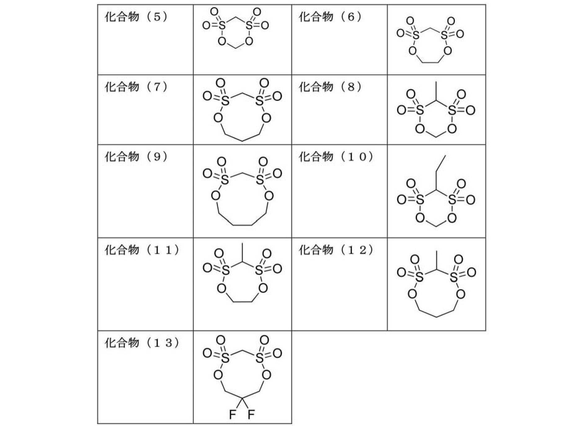

第2の添加剤は、ビニレンカーボネート、フルオロエチレンカーボネート、ビニルエチレンカーボネート、1,3-プロパンスルトン、1,4-ブタンスルトン、1,3-プロペンスルトン、スクシノニトリル、およびアジポニトリルからなる群から選択される添加剤である。これらは1種のみが単独で用いられてもよいし、2種以上が併用されてもよい。この第2の添加剤を上述した第1の添加剤と併用することで、負極活物質の表面に積層構造の安定なSEI皮膜を形成することができ、さらなる高耐久性電池を得ることができる。なお、第2の添加剤は、最も貴な還元電位を有する非水溶媒よりも貴な還元電位を有するものであることが好ましい。かような還元電位を有することによって、非水溶媒が分解されるよりも前に第2の添加剤が還元分解されて負極活物質の表面に緻密で安定なSEI皮膜を形成することができる。また、第2の添加剤の還元分解によって形成されたSEI皮膜は、最も貴な還元電位で分解する第1の添加剤との混合膜とならないため、各添加剤が有する本来の機能が発現しやすいという利点もある。 (Second additive)
The second additive is selected from the group consisting of vinylene carbonate, fluoroethylene carbonate, vinyl ethylene carbonate, 1,3-propane sultone, 1,4-butane sultone, 1,3-propene sultone, succinonitrile, and adiponitrile. Additive. These may be used alone or in combination of two or more. By using this second additive in combination with the above-mentioned first additive, a stable SEI film having a laminated structure can be formed on the surface of the negative electrode active material, and a further highly durable battery can be obtained. . In addition, it is preferable that a 2nd additive has a noble reduction potential rather than the non-aqueous solvent which has the most noble reduction potential. By having such a reduction potential, the second additive can be reduced and decomposed before the nonaqueous solvent is decomposed to form a dense and stable SEI film on the surface of the negative electrode active material. In addition, since the SEI film formed by reductive decomposition of the second additive does not become a mixed film with the first additive that decomposes at the most noble reduction potential, the original function of each additive is expressed. There is also an advantage that it is easy.
第3の添加剤は、上述した第1の添加剤の還元電位よりも卑で第2の添加剤の還元電位よりも貴な還元電位を有する添加剤である。かような第3の添加剤としては、例えば、無水コハク酸、グルタル酸、アジピン酸等が挙げられる。なかでも、耐久性向上という観点から、第3の添加剤が用いられる場合、当該第3の添加剤は無水コハク酸であることが好ましい。 (Third additive)
The third additive is an additive having a reduction potential that is lower than the reduction potential of the first additive and nobler than the reduction potential of the second additive. Examples of such a third additive include succinic anhydride, glutaric acid, and adipic acid. Among these, from the viewpoint of improving durability, when the third additive is used, the third additive is preferably succinic anhydride.
その他の添加剤は、上述した第1~第3の添加剤以外の添加剤である。すなわち、上述した第1~第3の添加剤の定義を満たさず、酸化還元分解電位を有し、電解質塩、非水溶媒および添加剤の合計量100質量%に対して含有量が5質量%未満である物質は、その他の添加剤として用いられうる。かようなその他の添加剤としては、例えば、非水溶媒として上述した化合物が該当しうる。 (Other additives)
The other additive is an additive other than the first to third additives described above. That is, it does not satisfy the definitions of the first to third additives described above, has an oxidation-reduction decomposition potential, and the content is 5% by mass with respect to 100% by mass of the total amount of the electrolyte salt, the nonaqueous solvent and the additive. Substances that are less than can be used as other additives. As such other additives, for example, the compounds described above as non-aqueous solvents may be applicable.
0.21≦A×L/SSA≦0.69 かつ 0.51≦B×L/SSA≦1.5
を満たす点に特徴がある。この2つの関係式は、第1の添加剤および第2の添加剤の添加量について、負極活物質の単位比表面積あたりの適正範囲が存在するという本発明者らによって見出された知見を数式化したものである。 The non-aqueous electrolyte secondary battery according to the present embodiment includes a non-aqueous solvent and an electrolyte salt in which the BET specific surface area of the negative electrode active material described above is SSA [m 2 / g], and the amount of the first additive added in the electrolyte. And the ratio of the addition amount of the second additive in the electrolyte to the total amount of the non-aqueous solvent and the electrolyte salt is B [mass%]. Using the ratio of electrolytic mass to the total pore volume of the negative electrode and separator (liquid coefficient L),
0.21 ≦ A × L / SSA ≦ 0.69 and 0.51 ≦ B × L / SSA ≦ 1.5
There is a feature in the point to satisfy. These two relational expressions express the knowledge found by the present inventors that there is an appropriate range per unit specific surface area of the negative electrode active material with respect to the addition amount of the first additive and the second additive. It has become.
集電板(25、27)を構成する材料は、特に制限されず、リチウムイオン二次電池用の集電板として従来用いられている公知の高導電性材料が用いられうる。集電板の構成材料としては、例えば、アルミニウム、銅、チタン、ニッケル、ステンレス鋼(SUS)、これらの合金等の金属材料が好ましい。軽量、耐食性、高導電性の観点から、より好ましくはアルミニウム、銅であり、特に好ましくはアルミニウムである。なお、正極集電板27と負極集電板25とでは、同一の材料が用いられてもよいし、異なる材料が用いられてもよい。 [Positive electrode current collector and negative electrode current collector]
The material which comprises a current collector plate (25, 27) is not restrict | limited in particular, The well-known highly electroconductive material conventionally used as a current collector plate for lithium ion secondary batteries can be used. As a constituent material of the current collector plate, for example, metal materials such as aluminum, copper, titanium, nickel, stainless steel (SUS), and alloys thereof are preferable. From the viewpoint of light weight, corrosion resistance, and high conductivity, aluminum and copper are more preferable, and aluminum is particularly preferable. In addition, the same material may be used for the positive electrode
また、図示は省略するが、集電体11と集電板(25、27)との間を正極リードや負極リードを介して電気的に接続してもよい。正極および負極リードの構成材料としては、公知のリチウムイオン二次電池において用いられる材料が同様に採用されうる。なお、外装から取り出された部分は、周辺機器や配線などに接触して漏電したりして製品(例えば、自動車部品、特に電子機器等)に影響を与えないように、耐熱絶縁性の熱収縮チューブなどにより被覆することが好ましい。 [Positive lead and negative lead]
Moreover, although illustration is abbreviate | omitted, you may electrically connect between the
電池外装体29としては、公知の金属缶ケースを用いることができるほか、発電要素を覆うことができる、アルミニウムを含むラミネートフィルムを用いた袋状のケースが用いられうる。該ラミネートフィルムには、例えば、PP、アルミニウム、ナイロンをこの順に積層してなる3層構造のラミネートフィルム等を用いることができるが、これらに何ら制限されるものではない。高出力化や冷却性能に優れ、EV、HEV用の大型機器用電池に好適に利用することができるという観点から、ラミネートフィルムが望ましい。また、外部から掛かる発電要素への群圧を容易に調整することができ、所望の電解液層厚みへと調整容易であることから、外装体はアルミネートラミネートがより好ましい。 [Battery exterior]
As the battery
図2は、本発明の電池の代表的な実施形態である扁平な非水電解質二次電池の外観を表した斜視図である。この非水電解質二次電池のように、本発明における好ましい実施形態によれば、アルミニウムを含むラミネートフィルムからなる電池外装体に前記発電要素が封入されてなる構成を有する扁平積層型ラミネート電池が提供される。 [Cell size]
FIG. 2 is a perspective view showing the appearance of a flat nonaqueous electrolyte secondary battery which is a typical embodiment of the battery of the present invention. Like this non-aqueous electrolyte secondary battery, according to a preferred embodiment of the present invention, there is provided a flat laminated laminate battery having a configuration in which the power generation element is enclosed in a battery exterior body made of a laminate film containing aluminum. Is done.
一般的な電気自動車では、一回の充電による走行距離(航続距離)は100kmが市場要求である。かような航続距離を考慮すると、電池の体積エネルギー密度は157Wh/L以上であることが好ましく、かつ定格容量は20Wh以上であることが好ましい。 [Volume energy density and rated discharge capacity]
In a general electric vehicle, a travel distance (cruising range) by a single charge is 100 km. Considering such a cruising distance, the volume energy density of the battery is preferably 157 Wh / L or more, and the rated capacity is preferably 20 Wh or more.
所望の被膜形成が行われるように、それぞれの添加剤の分解電位で保持することが望ましい。例えば、電流は0.1Cで充電し、所望の電圧で1時間保持する。 [Battery charging method]
It is desirable to maintain the decomposition potential of each additive so that the desired film formation can be achieved. For example, the current is charged at 0.1 C and held at a desired voltage for 1 hour.
組電池は、電池を複数個接続して構成した物である。詳しくは少なくとも2つ以上用いて、直列化あるいは並列化あるいはその両方で構成されるものである。直列、並列化することで容量および電圧を自由に調節することが可能になる。 [Battery]
The assembled battery is configured by connecting a plurality of batteries. Specifically, at least two or more are used, and are configured by serialization, parallelization, or both. Capacitance and voltage can be freely adjusted by paralleling in series.
本発明の非水電解質二次電池は、長期使用しても放電容量が維持され、サイクル特性が良好である。さらに、体積エネルギー密度が高い。電気自動車やハイブリッド電気自動車や燃料電池車やハイブリッド燃料電池自動車などの車両用途においては、電気・携帯電子機器用途と比較して、高容量、大型化が求められるとともに、長寿命化が必要となる。したがって、上記非水電解質二次電池は、車両用の電源として、例えば、車両駆動用電源や補助電源に好適に利用することができる。 [vehicle]
The nonaqueous electrolyte secondary battery of the present invention maintains a discharge capacity even when used for a long period of time, and has good cycle characteristics. Furthermore, the volume energy density is high. Vehicle applications such as electric vehicles, hybrid electric vehicles, fuel cell vehicles, and hybrid fuel cell vehicles require higher capacity, larger size, and longer life than electric and portable electronic devices. . Therefore, the nonaqueous electrolyte secondary battery can be suitably used as a vehicle power source, for example, a vehicle driving power source or an auxiliary power source.
[参考例1]
(1)正極の作製
正極活物質であるNMC複合酸化物(LiNi0.5Mn0.3Co0.2O2、平均二次粒子径(D50)=10μm)を95質量%、導電助剤として導電性カーボンブラック(super-P)2質量%、バインダーとしてポリフッ化ビニリデン(PVdF)3質量%、およびスラリー粘度調整溶媒であるN-メチル-2-ピロリドン(NMP)を適量混合して、正極活物質スラリーを調製した。 ≪Production of laminated battery≫
[Reference Example 1]
(1) Production of positive electrode 95% by mass of NMC composite oxide (LiNi 0.5 Mn 0.3 Co 0.2 O 2 , average secondary particle diameter (D50) = 10 μm) which is a positive electrode active material, conductive additive As a positive electrode, 2% by mass of conductive carbon black (super-P) as a binder, 3% by mass of polyvinylidene fluoride (PVdF) as a binder, and N-methyl-2-pyrrolidone (NMP) which is a slurry viscosity adjusting solvent are mixed. An active material slurry was prepared.
負極活物質として天然黒鉛(表面に非晶質コーティング層を有する、平均粒子径(D50)=18μm、BET比表面積(SSA)=1.6m2/g)を用い、この負極活物質96質量%、導電助剤として導電性カーボンブラック(super-P)1質量%、バインダーとしてカルボキシメチルセルロース(CMC)1質量%およびスチレン-ブタジエン共重合体(SBR)2質量%を精製水中に分散させて、負極活物質スラリーを調製した。なお、ここで用いた負極活物質を「活物質(1)」とも称する。 (3) Production of negative electrode Natural graphite (with an amorphous coating layer on the surface, average particle diameter (D50) = 18 μm, BET specific surface area (SSA) = 1.6 m 2 / g) was used as the negative electrode active material. 96% by mass of negative electrode active material, 1% by mass of conductive carbon black (super-P) as a conductive auxiliary agent, 1% by mass of carboxymethyl cellulose (CMC) and 2% by mass of styrene-butadiene copolymer (SBR) as purified binder To prepare a negative electrode active material slurry. The negative electrode active material used here is also referred to as “active material (1)”.
上記で得られた正極(200mm四方にカット)および負極(202mm四方にカット)をそれぞれセパレータ(セルガード♯2500、ポリプロピレン微多孔膜、サイズ204mm四方)を介して交互に積層(正極3層、負極4層)することで積層体を作製した。この積層体の正負極にタブ(集電板)を溶接し、これをアルミラミネートフィルムで挟んで三辺を封止した。その後、所定量の非水電解液を注入し、残りの辺を真空封止して、ラミネート電池を作製した。なお、非水電解液としては、1.0M LiPF6をエチレンカーボネート(EC)とジエチルカーボネート(DEC)との混合溶媒(体積比3:7、3EC7DEC)に溶解した溶液に、添加剤としてビニレンカーボネート(VC、第2の添加剤に相当)を1質量%(電解質塩と混合溶媒との合計質量に対する質量百分率)の濃度で添加したものを用いた。また、非水電解液の注液量は、正極、負極およびセパレータの総空孔体積に対する非水電解質液量の比率(液係数L)が1.5となる量とした。 (4) Production of laminated battery The positive electrode (cut in 200 mm square) and the negative electrode (cut in 202 mm square) obtained above are alternately laminated via separators (Celguard # 2500, polypropylene microporous membrane, size 204 mm square), respectively. (A positive electrode 3 layers, a negative electrode 4 layers) was made to produce a laminate. A tab (current collector plate) was welded to the positive and negative electrodes of this laminate, and this was sandwiched between aluminum laminate films to seal three sides. Thereafter, a predetermined amount of non-aqueous electrolyte was injected, and the remaining sides were vacuum sealed to produce a laminated battery. As the non-aqueous electrolyte, 1.0M LiPF 6 was dissolved in a mixed solvent of ethylene carbonate (EC) and diethyl carbonate (DEC) (volume ratio 3: 7, 3EC7DEC), and vinylene carbonate as an additive. (VC, corresponding to the second additive) added at a concentration of 1% by mass (mass percentage with respect to the total mass of the electrolyte salt and the mixed solvent) was used. The amount of the nonaqueous electrolyte solution injected was such that the ratio of the nonaqueous electrolyte solution amount (liquid coefficient L) to the total pore volume of the positive electrode, the negative electrode, and the separator was 1.5.
非水電解液に添加される添加剤の種類および濃度(電解質塩と混合溶媒との合計質量に対する質量百分率)を、下記の表4に示すように変更したこと以外は、上述した参考例1と同様の手法により、比較例1~7および実施例1~9のラミネート電池を作製した。 [Comparative Examples 1 to 7 and Examples 1 to 9]
Reference Example 1 described above except that the type and concentration of the additive added to the non-aqueous electrolyte (mass percentage with respect to the total mass of the electrolyte salt and the mixed solvent) were changed as shown in Table 4 below. In the same manner, laminate batteries of Comparative Examples 1 to 7 and Examples 1 to 9 were produced.
負極活物質として、天然黒鉛(表面に非晶質コーティング層を有する、平均粒子径(D50)=10μm、BET比表面積(SSA)=3.5m2/g)を代わりに用いたこと以外は、上述した参考例1と同様の手法により、参考例2のラミネート電池を作製した。なお、ここで用いた負極活物質を「活物質(2)」とも称する。 [Reference Example 2]
As a negative electrode active material, natural graphite (with an amorphous coating layer on the surface, average particle diameter (D50) = 10 μm, BET specific surface area (SSA) = 3.5 m 2 / g) was used instead. A laminated battery of Reference Example 2 was produced by the same method as Reference Example 1 described above. The negative electrode active material used here is also referred to as “active material (2)”.
非水電解液に添加される添加剤の種類および量を、下記の表5に示すように変更したこと以外は、上述した参考例2と同様の手法により、比較例8~15および実施例10~38のラミネート電池を作製した。 [Comparative Examples 8 to 15 and Examples 10 to 38]
Comparative Examples 8 to 15 and Example 10 were carried out in the same manner as in Reference Example 2 described above, except that the type and amount of additives added to the non-aqueous electrolyte were changed as shown in Table 5 below. 38 laminated batteries were produced.
本実施例で用いた添加剤の還元電位を以下の手法により測定したところ、メチレンメタンジスルホネート(MMDS)は1.5V、ビニレンカーボネート(VC)は1.15V、フルオロエチレンカーボネート(FEC)は1.0V、無水コハク酸(Suc)は1.3V、エチレンカーボネート(EC)は0.9V、ジエチルカーボネート(DEC)は0.3Vであった。 ≪Measurement of reduction potential≫
When the reduction potential of the additive used in this example was measured by the following method, methylenemethane disulfonate (MMDS) was 1.5 V, vinylene carbonate (VC) was 1.15 V, and fluoroethylene carbonate (FEC) was 1. 0.0V, succinic anhydride (Suc) was 1.3V, ethylene carbonate (EC) was 0.9V, and diethyl carbonate (DEC) was 0.3V.
還元電位は、サイクリックボルタンメトリーの測定により得られるサイクリックボルタノグラムにより得られる。具体的には、まず、エチレンカーボネート(EC)とジエチルカーボネート(DEC)とをEC/DEC=1/1(体積比)で混合した非水溶媒に、電解質塩としてLiPF6を濃度が1.0Mとなるように溶解して電解液を調製する。次いで、この電解液100質量%に対して1質量%の添加剤を加えて添加剤(非水溶媒)入りの電解液を作製する。次に、黒鉛負極を作用極、リチウム金属を対極および参照極とした三極式セルにこの電解液を加えて電気化学セルとする。作用極の電位を開回路電位から卑な電位に0.1mV/秒の走査速度で変化させたときの電流値を測定する。添加剤を含まない電解液を用いた際の測定値をブランクとして、添加剤を加えた際に特徴的に観察される還元分解ピークのうち、最も貴なピークの電位を添加剤の還元電位とする。 (Measurement method of reduction potential)
The reduction potential is obtained by a cyclic voltammogram obtained by measurement of cyclic voltammetry. Specifically, first, in a non-aqueous solvent in which ethylene carbonate (EC) and diethyl carbonate (DEC) are mixed at EC / DEC = 1/1 (volume ratio), LiPF 6 as an electrolyte salt has a concentration of 1.0M. An electrolytic solution is prepared by dissolving so as to be. Subsequently, 1 mass% additive is added with respect to 100 mass% of this electrolyte solution, and the electrolyte solution containing an additive (nonaqueous solvent) is produced. Next, this electrolytic solution is added to a triode cell having a graphite negative electrode as a working electrode and lithium metal as a counter electrode and a reference electrode to form an electrochemical cell. A current value is measured when the potential of the working electrode is changed from an open circuit potential to a base potential at a scanning speed of 0.1 mV / sec. The measured value when using an electrolyte containing no additive is blank, and the reductive decomposition peak that is characteristically observed when the additive is added is the most noble peak potential as the additive reduction potential. To do.
上記で作製したラミネート電池について、以下の評価を行った。結果を下記の表4および表5に示す。なお、表4および表5に示す結果は、比較例1~7および実施例1~9については参考例1の値を100とした相対値であり、比較例8~15および実施例10~38については参考例2の値を100とした相対値である。また、表4および表5には、A×L/SSA、B×L/SSA、(A+C)×L/SSA、B/AおよびB/(A+C)の値を併せて記載している。 ≪Evaluation of laminated battery≫
The following evaluation was performed about the laminated battery produced above. The results are shown in Table 4 and Table 5 below. The results shown in Tables 4 and 5 are relative values with respect to Comparative Examples 1 to 7 and Examples 1 to 9, with the value of Reference Example 1 being 100, and Comparative Examples 8 to 15 and Examples 10 to 38. Is a relative value with the value of Reference Example 2 as 100. Tables 4 and 5 also list values of A × L / SSA, B × L / SSA, (A + C) × L / SSA, B / A, and B / (A + C).
まず、設計容量に対して0.1Cのレートでセル電圧が4.15Vとなるまで定電流充電を行った。次いで、SOC50%から20秒間、1Cのレートで定電流放電を行い、その際の電圧降下値から、電池の内部抵抗値を測定した。この内部抵抗値は小さいほど入出力特性に優れていることを示す。 [Evaluation (1): Measurement of internal resistance]
First, constant current charging was performed until the cell voltage reached 4.15 V at a rate of 0.1 C with respect to the design capacity. Next, constant current discharge was performed at a rate of 1 C for 20 seconds from SOC 50%, and the internal resistance value of the battery was measured from the voltage drop value at that time. A smaller internal resistance value indicates better input / output characteristics.
50℃環境下、セル電圧4.15~2.5Vの範囲で、1Cのレートで1000サイクルの充放電サイクル試験を行った。そして、初期(1サイクル目)の放電容量に対する1000サイクル目の放電容量の維持率を算出した。この値が大きいほど、サイクル耐久性に優れていることを示す。 [Evaluation (2): Measurement of capacity retention rate (cycle durability)]
Under a 50 ° C. environment, a 1000 cycle charge / discharge cycle test was performed at a rate of 1 C in a cell voltage range of 4.15 to 2.5 V. And the maintenance rate of the discharge capacity of 1000th cycle with respect to the initial (1st cycle) discharge capacity was computed. It shows that it is excellent in cycle durability, so that this value is large.
50℃環境下、セル電圧が4.15Vの状態で、電池を2ヶ月間静置した。その後、セル電圧4.15~2.5Vの範囲で、1Cのレートで放電試験を行い、放電容量を測定した。そして、上記「容量維持率(サイクル耐久性)の測定」で測定した1サイクル目の放電容量に対する保存後の放電容量の維持率を算出した。この値が大きいほど、保存耐久性に優れていることを示す。 [Evaluation (3): Measurement of capacity retention rate after storage test (storage durability)]
Under a 50 ° C. environment, the battery was allowed to stand for 2 months with a cell voltage of 4.15V. Thereafter, a discharge test was performed at a rate of 1 C in a cell voltage range of 4.15 to 2.5 V, and a discharge capacity was measured. Then, the retention rate of the discharge capacity after storage with respect to the discharge capacity at the first cycle measured in the above “measurement of capacity retention rate (cycle durability)” was calculated. It shows that it is excellent in storage durability, so that this value is large.

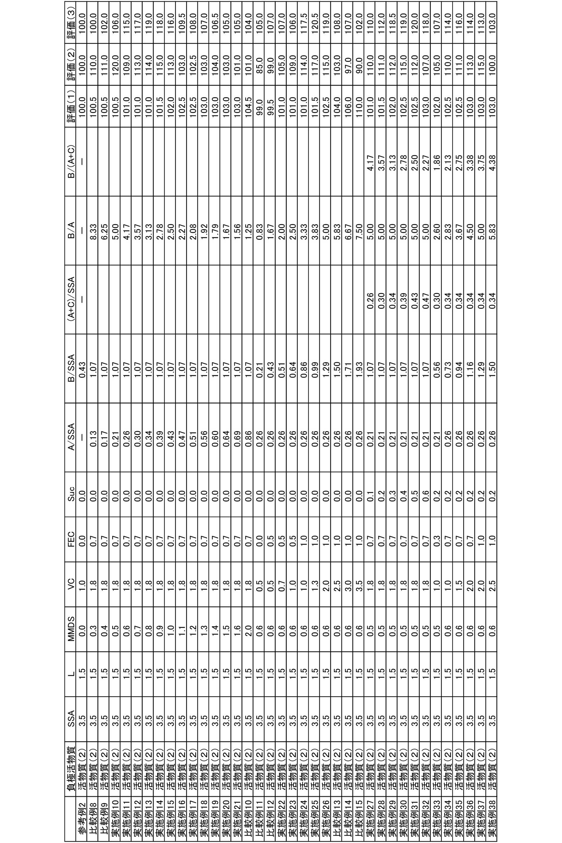
11 負極集電体、
12 正極集電体、
13 負極活物質層、
15 正極活物質層、
17 セパレータ、
19 単電池層、
21、57 発電要素、
25 負極集電板、
27 正極集電板、
29、52 電池外装材、
58 正極タブ、
59 負極タブ。 10, 50 lithium ion secondary battery,
11 negative electrode current collector,
12 positive electrode current collector,
13 negative electrode active material layer,
15 positive electrode active material layer,
17 separator,
19 cell layer,
21, 57 power generation element,
25 negative current collector,
27 positive current collector,
29, 52 Battery exterior material,
58 positive electrode tab,
59 Negative electrode tab.
Claims (11)
- 正極集電体の表面に正極活物質を含む正極活物質層が形成されてなる正極と、
負極集電体の表面に負極活物質を含む負極活物質層が形成されてなる負極と、
電解質を含むセパレータと、
を含む発電要素を有し、
前記電解質が、電解質塩、前記電解質塩を溶解可能な非水溶媒、第1の添加剤、および前記第1の添加剤の還元電位よりも卑な還元電位を有する第2の添加剤を含み、
この際、前記第1の添加剤は、下記式(1):

で表されるオキサレート化合物、および下記式(2):

で表されるジスルホン酸エステル化合物からなる群から選択される少なくとも1種であり、かつ、前記第2の添加剤は、ビニレンカーボネート、フルオロエチレンカーボネート、ビニルエチレンカーボネート、1,3-プロパンスルトン、1,4-ブタンスルトン、1,3-プロペンスルトン、スクシノニトリル、およびアジポニトリルからなる群から選択される少なくとも1種であり、
前記負極活物質のBET比表面積をSSA[m2/g]とし、正極、負極およびセパレータの総空孔体積に対する電解質量の比率(液係数)をLとし、前記電解質における前記第1の添加剤の添加量の前記非水溶媒と前記電解質塩との合計量に対する割合をA[質量%]とし、前記電解質における前記第2の添加剤の添加量の前記非水溶媒と前記電解質塩との合計量に対する割合をB[質量%]としたときに、
0.21≦A×L/SSA≦0.69 かつ 0.51≦B×L/SSA≦1.5
を満たすことを特徴とする、非水電解質二次電池。 A positive electrode in which a positive electrode active material layer containing a positive electrode active material is formed on the surface of the positive electrode current collector;
A negative electrode in which a negative electrode active material layer containing a negative electrode active material is formed on the surface of the negative electrode current collector;
A separator containing an electrolyte;
A power generation element including
The electrolyte includes an electrolyte salt, a nonaqueous solvent capable of dissolving the electrolyte salt, a first additive, and a second additive having a reduction potential lower than that of the first additive;
At this time, the first additive has the following formula (1):
And an oxalate compound represented by the following formula (2):
And the second additive includes vinylene carbonate, fluoroethylene carbonate, vinylethylene carbonate, 1,3-propane sultone, 1 , 4-butane sultone, 1,3-propene sultone, succinonitrile, and at least one selected from the group consisting of adiponitrile,
The BET specific surface area of the negative electrode active material is SSA [m 2 / g], the ratio (liquid coefficient) of electrolytic mass to the total pore volume of the positive electrode, negative electrode and separator is L, and the first additive in the electrolyte The ratio of the addition amount of the nonaqueous solvent and the electrolyte salt to the total amount of A is defined as A [mass%], and the addition amount of the second additive in the electrolyte is the sum of the nonaqueous solvent and the electrolyte salt When the ratio to the amount is B [mass%],
0.21 ≦ A × L / SSA ≦ 0.69 and 0.51 ≦ B × L / SSA ≦ 1.5
The nonaqueous electrolyte secondary battery characterized by satisfy | filling. - 前記オキサレート化合物が、リチウムテトラフルオロオキサレートフォスフェート、リチウムジフルオロオキサレートボレート、リチウムビスオキサレートボレート、およびリチウムジフルオロビスオキサレートフォスフェートからなる群から選択される少なくとも1種である、請求項1に記載の非水電解質二次電池。 The oxalate compound is at least one selected from the group consisting of lithium tetrafluorooxalate phosphate, lithium difluorooxalate borate, lithium bisoxalate borate, and lithium difluorobisoxalate phosphate. The nonaqueous electrolyte secondary battery as described.
- 前記ジスルホン酸エステル化合物が、メチレンメタンジスルホネート、エチレンメタンジスルホネート、プロピレンメタンジスルホネート、ジメチルメタンジスルホネート、ジエチルメタンジスルホネート、およびエチルメチルメタンジスルホネートからなる群から選択される少なくとも1種である、請求項1または2に記載の非水電解質二次電池。 The disulfonate compound is at least one selected from the group consisting of methylene methane disulfonate, ethylene methane disulfonate, propylene methane disulfonate, dimethyl methane disulfonate, diethyl methane disulfonate, and ethyl methyl methane disulfonate. The nonaqueous electrolyte secondary battery according to claim 1 or 2.
- 2.50≦B/A≦4.33をさらに満たす、請求項1~3のいずれか1項に記載の非水電解質二次電池。 The nonaqueous electrolyte secondary battery according to any one of claims 1 to 3, further satisfying 2.50≤B / A≤4.33.
- 前記負極活物質が、黒鉛を含む、請求項1~4のいずれか1項に記載の非水電解質二次電池。 The nonaqueous electrolyte secondary battery according to any one of claims 1 to 4, wherein the negative electrode active material contains graphite.
- 前記非水溶媒が、エチレンカーボネートを含む、請求項1~5のいずれか1項に記載の非水電解質二次電池。 The nonaqueous electrolyte secondary battery according to any one of claims 1 to 5, wherein the nonaqueous solvent includes ethylene carbonate.
- 前記電解質が、前記第1の添加剤の還元電位よりも卑で前記第2の添加剤の還元電位よりも貴な還元電位を有する第3の添加剤をさらに含み、
前記電解質における前記第3の添加剤の添加量の前記非水溶媒と前記電解質塩との合計量に対する割合をC[質量%]としたときに、
0.17≦(A+C)×L/SSA≦0.38
を満たす、請求項1~6のいずれか1項に記載の非水電解質二次電池。 The electrolyte further includes a third additive having a reduction potential that is lower than the reduction potential of the first additive and nobler than the reduction potential of the second additive;
When the ratio of the addition amount of the third additive in the electrolyte to the total amount of the nonaqueous solvent and the electrolyte salt is C [mass%],
0.17 ≦ (A + C) × L / SSA ≦ 0.38
The nonaqueous electrolyte secondary battery according to any one of claims 1 to 6, wherein - 前記第3の添加剤が、無水コハク酸、グルタル酸およびアジピン酸からなる群から選択される少なくとも1種である、請求項7に記載の非水電解質二次電池。 The non-aqueous electrolyte secondary battery according to claim 7, wherein the third additive is at least one selected from the group consisting of succinic anhydride, glutaric acid, and adipic acid.
- 2.13≦B/(A+C)≦3.75をさらに満たす、請求項7または8に記載の非水電解質二次電池。 The nonaqueous electrolyte secondary battery according to claim 7 or 8, further satisfying 2.13 ≦ B / (A + C) ≦ 3.75.
- 定格容量に対する電池面積(電池外装体まで含めた電池の投影面積)の比の値が5cm2/Ah以上であり、かつ、定格容量が3Ah以上である、請求項1~9のいずれか1項に記載の非水電解質二次電池。 The value of the ratio of the battery area to the rated capacity (projected area of the battery including the battery outer casing) is 5 cm 2 / Ah or more, and the rated capacity is 3 Ah or more. The non-aqueous electrolyte secondary battery described in 1.
- リチウムイオン二次電池である、請求項1~10のいずれか1項に記載の非水電解質二次電池。 The nonaqueous electrolyte secondary battery according to any one of claims 1 to 10, which is a lithium ion secondary battery.
Priority Applications (7)
| Application Number | Priority Date | Filing Date | Title |
|---|---|---|---|
| PCT/JP2015/069771 WO2017006480A1 (en) | 2015-07-09 | 2015-07-09 | Nonaqueous electrolyte secondary battery |
| JP2017527051A JP6575972B2 (en) | 2015-07-09 | 2015-07-09 | Nonaqueous electrolyte secondary battery |
| EP15897741.3A EP3322023B1 (en) | 2015-07-09 | 2015-07-09 | Nonaqueous electrolyte secondary battery |
| US15/740,366 US10270127B2 (en) | 2015-07-09 | 2015-07-09 | Nonaqueous electrolyte secondary battery |
| CN201580081565.XA CN107851832B (en) | 2015-07-09 | 2015-07-09 | Nonaqueous electrolyte secondary battery |
| MYPI2018700087A MY169005A (en) | 2015-07-09 | 2015-07-09 | Nonaqueous electrolyte secondary battery |
| KR1020187002398A KR101944226B1 (en) | 2015-07-09 | 2015-07-09 | Non-aqueous electrolyte secondary battery |
Applications Claiming Priority (1)
| Application Number | Priority Date | Filing Date | Title |
|---|---|---|---|
| PCT/JP2015/069771 WO2017006480A1 (en) | 2015-07-09 | 2015-07-09 | Nonaqueous electrolyte secondary battery |
Publications (1)
| Publication Number | Publication Date |
|---|---|
| WO2017006480A1 true WO2017006480A1 (en) | 2017-01-12 |
Family
ID=57685020
Family Applications (1)
| Application Number | Title | Priority Date | Filing Date |
|---|---|---|---|
| PCT/JP2015/069771 WO2017006480A1 (en) | 2015-07-09 | 2015-07-09 | Nonaqueous electrolyte secondary battery |
Country Status (6)
| Country | Link |
|---|---|
| US (1) | US10270127B2 (en) |
| EP (1) | EP3322023B1 (en) |
| JP (1) | JP6575972B2 (en) |
| KR (1) | KR101944226B1 (en) |
| CN (1) | CN107851832B (en) |
| WO (1) | WO2017006480A1 (en) |
Cited By (3)
| Publication number | Priority date | Publication date | Assignee | Title |
|---|---|---|---|---|
| JP2021516858A (en) * | 2018-05-03 | 2021-07-08 | エルジー・ケム・リミテッド | A method for manufacturing an electrode containing a polymer-based solid electrolyte and an electrode manufactured by this method. |
| JP2021516859A (en) * | 2018-05-03 | 2021-07-08 | エルジー・ケム・リミテッド | A method for manufacturing an electrode containing a polymer-based solid electrolyte and an electrode manufactured by this method. |
| CN115692855A (en) * | 2022-12-29 | 2023-02-03 | 湖南法恩莱特新能源科技有限公司 | Overcharge-preventing additive for lithium battery electrolyte and lithium battery electrolyte comprising same |
Families Citing this family (25)
| Publication number | Priority date | Publication date | Assignee | Title |
|---|---|---|---|---|
| JP7133776B2 (en) * | 2018-04-16 | 2022-09-09 | パナソニックIpマネジメント株式会社 | Non-aqueous electrolyte secondary battery |
| CN110660962B (en) * | 2018-06-29 | 2021-02-02 | 宁德时代新能源科技股份有限公司 | Secondary battery |
| CN109950474B (en) * | 2018-06-29 | 2020-04-24 | 宁德时代新能源科技股份有限公司 | Lithium ion battery |
| CN110010903B (en) * | 2018-06-29 | 2020-07-17 | 宁德时代新能源科技股份有限公司 | Positive pole piece and battery |
| KR102259218B1 (en) | 2018-07-03 | 2021-05-31 | 삼성에스디아이 주식회사 | Electrode for lithium secondary battery, and lithium secondary battery including the same |
| KR102259219B1 (en) | 2018-07-03 | 2021-05-31 | 삼성에스디아이 주식회사 | Lithium secondary battery |
| CN111740160B (en) * | 2018-09-21 | 2022-04-15 | 宁德新能源科技有限公司 | Electrolyte and electrochemical device comprising the same |
| KR102323950B1 (en) | 2018-12-12 | 2021-11-08 | 삼성에스디아이 주식회사 | Electrode for rechargeable lithium battery and rechargeable lithium battery including same |
| CN113169378A (en) * | 2018-12-18 | 2021-07-23 | 日本碍子株式会社 | Lithium secondary battery |
| JP6896783B2 (en) * | 2019-03-11 | 2021-06-30 | 株式会社東芝 | Rechargeable battery system, rechargeable battery, and assembled battery system |
| CN109994739B (en) * | 2019-03-25 | 2021-07-23 | 宁德新能源科技有限公司 | Negative pole piece, electrochemical device comprising same and electronic device |
| KR102487628B1 (en) | 2019-05-03 | 2023-01-12 | 삼성에스디아이 주식회사 | Rechargeable lithium battery |
| KR102425515B1 (en) | 2019-05-03 | 2022-07-25 | 삼성에스디아이 주식회사 | Lithium secondary battery |
| KR102425513B1 (en) | 2019-05-03 | 2022-07-25 | 삼성에스디아이 주식회사 | Lithium secondary battery |
| KR102425514B1 (en) | 2019-05-03 | 2022-07-25 | 삼성에스디아이 주식회사 | Lithium secondary battery |
| KR102492831B1 (en) | 2019-05-03 | 2023-01-26 | 삼성에스디아이 주식회사 | Lithium secondary battery |
| KR102492832B1 (en) | 2019-05-03 | 2023-01-26 | 삼성에스디아이 주식회사 | Lithium secondary battery |
| CN112349960B (en) * | 2019-08-08 | 2021-12-07 | 宁德时代新能源科技股份有限公司 | Electrolyte and lithium ion battery |
| US11837698B2 (en) | 2019-12-24 | 2023-12-05 | Dongguan Amperex Technology Limited | Electrochemical device and electronic device |
| CN111082129B (en) * | 2019-12-24 | 2021-01-12 | 东莞新能源科技有限公司 | Electrochemical device and electronic device |
| CN111430795B (en) * | 2020-03-31 | 2021-06-04 | 宁德新能源科技有限公司 | Electrochemical device and electronic device comprising same |
| US20220149425A1 (en) * | 2020-11-07 | 2022-05-12 | Eocell Limited | Nonaqueous electrolyte for lithium ion secondary battery, and lithium ion secondary battery containing the same |
| KR20220105936A (en) * | 2021-01-21 | 2022-07-28 | 삼성에스디아이 주식회사 | Additive for electrolyte of lithium battery, organic electrolytic solution comprising the same and Lithium battery using the solution |
| CN115064770B (en) * | 2022-08-18 | 2022-12-06 | 深圳新宙邦科技股份有限公司 | Lithium ion battery |
| CN116470143B (en) * | 2023-06-19 | 2023-09-05 | 蔚来电池科技(安徽)有限公司 | Secondary battery and device |
Citations (4)
| Publication number | Priority date | Publication date | Assignee | Title |
|---|---|---|---|---|
| JP2006324194A (en) * | 2005-05-20 | 2006-11-30 | Nec Corp | Secondary battery |
| WO2013005502A1 (en) * | 2011-07-04 | 2013-01-10 | 日本電気株式会社 | Method for producing secondary battery |
| WO2013128679A1 (en) * | 2012-02-29 | 2013-09-06 | 新神戸電機株式会社 | Lithium-ion battery |
| JP2015069810A (en) * | 2013-09-27 | 2015-04-13 | オートモーティブエナジーサプライ株式会社 | Nonaqueous electrolyte secondary battery and method for manufacturing the same |
Family Cites Families (8)
| Publication number | Priority date | Publication date | Assignee | Title |
|---|---|---|---|---|
| JP4608735B2 (en) | 2000-05-16 | 2011-01-12 | ソニー株式会社 | Non-aqueous electrolyte secondary battery charging method |
| JP4703203B2 (en) * | 2005-02-03 | 2011-06-15 | 三洋電機株式会社 | Nonaqueous electrolyte secondary battery |
| JP5119182B2 (en) * | 2009-02-24 | 2013-01-16 | トヨタ自動車株式会社 | Method for producing lithium ion secondary battery |
| US8592085B2 (en) | 2009-10-22 | 2013-11-26 | Toda Kogyo Corporation | Nickel-cobalt-maganese-based compound particles and process for producing the nickel-cobalt-manganese-based compound particles, lithium composite oxide particles and process for producing the lithium composite oxide particles, and non-aqueous electrolyte secondary battery |
| WO2012017998A1 (en) * | 2010-08-05 | 2012-02-09 | 和光純薬工業株式会社 | Nonaqueous electrolyte solution, method for producing same, and nonaqueous electrolyte battery using the electrolyte solution |
| KR101569976B1 (en) * | 2012-02-29 | 2015-11-17 | 신코베덴키 가부시키가이샤 | Lithium ion battery |
| US20140370346A1 (en) | 2012-02-29 | 2014-12-18 | Shin-Kobe Electric Machinery Co., Ltd. | Lithium Ion Battery |
| JP5672508B2 (en) * | 2012-09-26 | 2015-02-18 | 株式会社デンソー | Nonaqueous electrolyte secondary battery |
-
2015
- 2015-07-09 CN CN201580081565.XA patent/CN107851832B/en active Active
- 2015-07-09 WO PCT/JP2015/069771 patent/WO2017006480A1/en active Application Filing
- 2015-07-09 JP JP2017527051A patent/JP6575972B2/en active Active
- 2015-07-09 KR KR1020187002398A patent/KR101944226B1/en active IP Right Grant
- 2015-07-09 EP EP15897741.3A patent/EP3322023B1/en active Active
- 2015-07-09 US US15/740,366 patent/US10270127B2/en active Active
Patent Citations (4)
| Publication number | Priority date | Publication date | Assignee | Title |
|---|---|---|---|---|
| JP2006324194A (en) * | 2005-05-20 | 2006-11-30 | Nec Corp | Secondary battery |
| WO2013005502A1 (en) * | 2011-07-04 | 2013-01-10 | 日本電気株式会社 | Method for producing secondary battery |
| WO2013128679A1 (en) * | 2012-02-29 | 2013-09-06 | 新神戸電機株式会社 | Lithium-ion battery |
| JP2015069810A (en) * | 2013-09-27 | 2015-04-13 | オートモーティブエナジーサプライ株式会社 | Nonaqueous electrolyte secondary battery and method for manufacturing the same |
Non-Patent Citations (1)
| Title |
|---|
| See also references of EP3322023A4 * |
Cited By (6)
| Publication number | Priority date | Publication date | Assignee | Title |
|---|---|---|---|---|
| JP2021516858A (en) * | 2018-05-03 | 2021-07-08 | エルジー・ケム・リミテッド | A method for manufacturing an electrode containing a polymer-based solid electrolyte and an electrode manufactured by this method. |
| JP2021516859A (en) * | 2018-05-03 | 2021-07-08 | エルジー・ケム・リミテッド | A method for manufacturing an electrode containing a polymer-based solid electrolyte and an electrode manufactured by this method. |
| JP7038848B2 (en) | 2018-05-03 | 2022-03-18 | エルジー エナジー ソリューション リミテッド | A method for manufacturing an electrode containing a polymer-based solid electrolyte and an electrode manufactured by the method. |
| JP7083914B2 (en) | 2018-05-03 | 2022-06-13 | エルジー エナジー ソリューション リミテッド | A method for manufacturing an electrode containing a polymer-based solid electrolyte and an electrode manufactured by the method. |
| CN115692855A (en) * | 2022-12-29 | 2023-02-03 | 湖南法恩莱特新能源科技有限公司 | Overcharge-preventing additive for lithium battery electrolyte and lithium battery electrolyte comprising same |
| CN115692855B (en) * | 2022-12-29 | 2023-04-04 | 湖南法恩莱特新能源科技有限公司 | Overcharge-preventing additive for lithium battery electrolyte and lithium battery electrolyte comprising same |
Also Published As
| Publication number | Publication date |
|---|---|
| EP3322023B1 (en) | 2020-10-28 |
| KR101944226B1 (en) | 2019-01-30 |
| CN107851832A (en) | 2018-03-27 |
| JP6575972B2 (en) | 2019-09-18 |
| EP3322023A1 (en) | 2018-05-16 |
| US10270127B2 (en) | 2019-04-23 |
| JPWO2017006480A1 (en) | 2018-04-05 |
| EP3322023A4 (en) | 2018-07-18 |
| CN107851832B (en) | 2020-06-09 |
| KR20180014192A (en) | 2018-02-07 |
| US20180191027A1 (en) | 2018-07-05 |
Similar Documents
| Publication | Publication Date | Title |
|---|---|---|
| JP6575972B2 (en) | Nonaqueous electrolyte secondary battery | |
| JP6112204B2 (en) | Non-aqueous electrolyte secondary battery positive electrode and non-aqueous electrolyte secondary battery using the same | |
| JP6070824B2 (en) | Non-aqueous electrolyte secondary battery positive electrode and non-aqueous electrolyte secondary battery using the same | |
| JP6176317B2 (en) | Non-aqueous electrolyte secondary battery positive electrode and non-aqueous electrolyte secondary battery using the same | |
| WO2014133063A1 (en) | Positive electrode active material, positive electrode material, positive electrode, and non-aqueous electrolyte secondary battery | |
| WO2014175355A1 (en) | Nonaqueous-electrolyte secondary battery | |
| JP6070822B2 (en) | Nonaqueous electrolyte secondary battery | |
| JP6070823B2 (en) | Nonaqueous electrolyte secondary battery | |
| WO2015156400A1 (en) | Positive electrode for electrical device, and electrical device using same | |
| WO2014175354A1 (en) | Nonaqueous-electrolyte secondary battery | |
| JP6241543B2 (en) | Electrical device | |
| WO2016103511A1 (en) | Electrical device | |
| KR102061442B1 (en) | Nonaqueous electrolyte secondary battery | |
| JP6528543B2 (en) | Positive electrode for non-aqueous electrolyte secondary battery and non-aqueous electrolyte secondary battery using the same | |
| JP2014216266A (en) | Discharge control system and discharge control method | |
| JP2017073281A (en) | Positive electrode material for nonaqueous electrolyte secondary battery, positive electrode for nonaqueous electrolyte secondary battery using the same, and nonaqueous electrolyte secondary battery | |
| JP2017004696A (en) | Positive electrode for nonaqueous electrolyte secondary battery | |
| JP6676305B2 (en) | Negative electrode active material for non-aqueous electrolyte secondary battery, and negative electrode for non-aqueous electrolyte secondary battery and non-aqueous electrolyte secondary battery using the same | |
| JP6519264B2 (en) | Positive electrode for non-aqueous electrolyte secondary battery and non-aqueous electrolyte secondary battery using the same | |
| JP2022158172A (en) | Manufacturing method of non-aqueous electrolyte secondary battery | |
| JP2015095330A (en) | Lithium ion secondary battery |
Legal Events
| Date | Code | Title | Description |
|---|---|---|---|
| 121 | Ep: the epo has been informed by wipo that ep was designated in this application |
Ref document number: 15897741 Country of ref document: EP Kind code of ref document: A1 |
|
| ENP | Entry into the national phase |
Ref document number: 2017527051 Country of ref document: JP Kind code of ref document: A |
|
| NENP | Non-entry into the national phase |
Ref country code: DE |
|
| ENP | Entry into the national phase |
Ref document number: 20187002398 Country of ref document: KR Kind code of ref document: A |
|
| WWE | Wipo information: entry into national phase |
Ref document number: 2015897741 Country of ref document: EP |