WO2017006476A1 - Pretreatment device, and analysis system provided with same - Google Patents
Pretreatment device, and analysis system provided with same Download PDFInfo
- Publication number
- WO2017006476A1 WO2017006476A1 PCT/JP2015/069736 JP2015069736W WO2017006476A1 WO 2017006476 A1 WO2017006476 A1 WO 2017006476A1 JP 2015069736 W JP2015069736 W JP 2015069736W WO 2017006476 A1 WO2017006476 A1 WO 2017006476A1
- Authority
- WO
- WIPO (PCT)
- Prior art keywords
- container
- pretreatment
- unit
- holding
- sample
- Prior art date
Links
Images


Classifications
-
- G—PHYSICS
- G01—MEASURING; TESTING
- G01N—INVESTIGATING OR ANALYSING MATERIALS BY DETERMINING THEIR CHEMICAL OR PHYSICAL PROPERTIES
- G01N30/00—Investigating or analysing materials by separation into components using adsorption, absorption or similar phenomena or using ion-exchange, e.g. chromatography or field flow fractionation
- G01N30/02—Column chromatography
- G01N30/04—Preparation or injection of sample to be analysed
- G01N30/06—Preparation
-
- G—PHYSICS
- G01—MEASURING; TESTING
- G01N—INVESTIGATING OR ANALYSING MATERIALS BY DETERMINING THEIR CHEMICAL OR PHYSICAL PROPERTIES
- G01N35/00—Automatic analysis not limited to methods or materials provided for in any single one of groups G01N1/00 - G01N33/00; Handling materials therefor
- G01N35/00584—Control arrangements for automatic analysers
- G01N35/0092—Scheduling
-
- G—PHYSICS
- G01—MEASURING; TESTING
- G01N—INVESTIGATING OR ANALYSING MATERIALS BY DETERMINING THEIR CHEMICAL OR PHYSICAL PROPERTIES
- G01N35/00—Automatic analysis not limited to methods or materials provided for in any single one of groups G01N1/00 - G01N33/00; Handling materials therefor
- G01N35/02—Automatic analysis not limited to methods or materials provided for in any single one of groups G01N1/00 - G01N33/00; Handling materials therefor using a plurality of sample containers moved by a conveyor system past one or more treatment or analysis stations
-
- G—PHYSICS
- G01—MEASURING; TESTING
- G01N—INVESTIGATING OR ANALYSING MATERIALS BY DETERMINING THEIR CHEMICAL OR PHYSICAL PROPERTIES
- G01N30/00—Investigating or analysing materials by separation into components using adsorption, absorption or similar phenomena or using ion-exchange, e.g. chromatography or field flow fractionation
- G01N30/02—Column chromatography
- G01N2030/022—Column chromatography characterised by the kind of separation mechanism
- G01N2030/027—Liquid chromatography
-
- G—PHYSICS
- G01—MEASURING; TESTING
- G01N—INVESTIGATING OR ANALYSING MATERIALS BY DETERMINING THEIR CHEMICAL OR PHYSICAL PROPERTIES
- G01N30/00—Investigating or analysing materials by separation into components using adsorption, absorption or similar phenomena or using ion-exchange, e.g. chromatography or field flow fractionation
- G01N30/02—Column chromatography
- G01N30/04—Preparation or injection of sample to be analysed
- G01N30/06—Preparation
- G01N2030/067—Preparation by reaction, e.g. derivatising the sample
-
- G—PHYSICS
- G01—MEASURING; TESTING
- G01N—INVESTIGATING OR ANALYSING MATERIALS BY DETERMINING THEIR CHEMICAL OR PHYSICAL PROPERTIES
- G01N30/00—Investigating or analysing materials by separation into components using adsorption, absorption or similar phenomena or using ion-exchange, e.g. chromatography or field flow fractionation
- G01N30/02—Column chromatography
- G01N30/62—Detectors specially adapted therefor
- G01N30/72—Mass spectrometers
- G01N30/7233—Mass spectrometers interfaced to liquid or supercritical fluid chromatograph
-
- G—PHYSICS
- G01—MEASURING; TESTING
- G01N—INVESTIGATING OR ANALYSING MATERIALS BY DETERMINING THEIR CHEMICAL OR PHYSICAL PROPERTIES
- G01N35/00—Automatic analysis not limited to methods or materials provided for in any single one of groups G01N1/00 - G01N33/00; Handling materials therefor
- G01N35/02—Automatic analysis not limited to methods or materials provided for in any single one of groups G01N1/00 - G01N33/00; Handling materials therefor using a plurality of sample containers moved by a conveyor system past one or more treatment or analysis stations
- G01N35/025—Automatic analysis not limited to methods or materials provided for in any single one of groups G01N1/00 - G01N33/00; Handling materials therefor using a plurality of sample containers moved by a conveyor system past one or more treatment or analysis stations having a carousel or turntable for reaction cells or cuvettes
-
- G—PHYSICS
- G01—MEASURING; TESTING
- G01N—INVESTIGATING OR ANALYSING MATERIALS BY DETERMINING THEIR CHEMICAL OR PHYSICAL PROPERTIES
- G01N35/00—Automatic analysis not limited to methods or materials provided for in any single one of groups G01N1/00 - G01N33/00; Handling materials therefor
- G01N35/02—Automatic analysis not limited to methods or materials provided for in any single one of groups G01N1/00 - G01N33/00; Handling materials therefor using a plurality of sample containers moved by a conveyor system past one or more treatment or analysis stations
- G01N35/04—Details of the conveyor system
Definitions
- the present invention relates to a pretreatment apparatus that performs pretreatment on a sample.
- the sample when analyzing components contained in a sample derived from a living body such as whole blood, serum, filter paper blood, and urine, the sample may be analyzed after being pretreated by a pretreatment device.
- the pretreatment include a process of removing a specific component unnecessary for analysis from a sample and extracting a necessary component, and a process of concentrating or drying the extracted sample.
- various configurations have been proposed as preprocessing devices that automatically execute such preprocessing (see, for example, Patent Document 1 below).
- Patent Document 1 discloses a configuration in which a plurality of cartridges (separation containers) having a separating agent that allows a sample to pass through and separates a specific component in the sample are held and conveyed by a common conveyance mechanism.
- the plurality of cartridges are sequentially transported by a transport mechanism to a pressure load mechanism provided at a predetermined position, and a sample is extracted by applying pressure to the pressure load mechanism.
- the plurality of tray containers (collection containers) that receive the extraction liquid from the cartridge are transported by a transport mechanism separate from the cartridge below the cartridge, whereby the sample is continuously extracted.
- pretreatment containers carriers into which samples are injected are held at a plurality of holding positions in the apparatus, and pretreatment can be performed by using these pretreatment containers in a certain order. It is done sequentially.
- the used pretreatment container is automatically discarded, and at the end of the analysis, the pretreatment containers at all holding positions are discarded, or the pretreatment containers are held only at some holding positions.
- a new pretreatment container is replenished to a holding position where the pretreatment container is not held, so that the pretreatment containers are held at all holding positions. Thereafter, when an operation for starting the analysis is performed, the pretreatment containers that are held in a certain holding position (first holding position) among the plurality of holding positions are used in order, and a series of preprocessing is executed.
- the analysis when the analysis is started, it is necessary to start the analysis after performing the work of replenishing the pretreatment container.
- the pretreatment containers were replenished even when the number of pretreatment containers used for the next analysis was sufficient.
- the analysis had to be started above, and the work was complicated.
- the present invention has been made in view of the above circumstances, and an object of the present invention is to provide a preprocessing apparatus capable of starting preprocessing by a simple operation and an analysis system including the preprocessing apparatus.
- the pretreatment apparatus is a pretreatment apparatus that performs pretreatment on a sample, and includes a container holding unit, a pretreatment unit, and a position setting receiving unit.
- the container holding unit holds a pretreatment container into which a sample is injected at a plurality of holding positions.
- the pretreatment unit sequentially performs pretreatment by using the pretreatment containers held at the holding positions of the container holding unit in a predetermined order.
- the position setting reception unit is configured to determine a holding position of a pretreatment container to be used first from among the plurality of holding positions when a series of preprocessing using a plurality of pretreatment containers is started by the preprocessing unit. Accept settings.
- the pre-processing apparatus may further include a position information storage unit that stores information related to the last used pre-processing container holding position when a series of pre-processing by the pre-processing unit is completed.
- the position setting receiving unit may receive a setting as to whether or not to determine a holding position of the pretreatment container to be used first based on information stored in the position information storage unit.
- a pre-processing when a series of pretreatments using a plurality of pretreatment containers is started, based on the information on the holding position of the pretreatment container used last in the previous pretreatment.
- the holding position where the pretreatment container is held can be automatically set as the holding position of the pretreatment container to be used first. Therefore, when starting a series of pre-processing without performing the operation
- the position setting reception unit may receive a setting as to whether or not to determine a predetermined holding position among the plurality of holding positions as a holding position of the pretreatment container to be used first.
- the pretreatment container when a series of pretreatment is started after performing an operation of replenishing the pretreatment container, the pretreatment container that first uses a certain holding position among the plurality of holding positions is held. The position can be determined. When the pretreatment container is replenished, the pretreatment container held in any holding position may be used first, so the pretreatment container held in a certain holding position should be used first. As a result, the operation during pre-processing can be simplified.
- the pre-processing apparatus may further include a container number receiving unit that receives an input of the number of pre-processing containers held in the container holding unit.
- the number of pretreatment containers held in the container holding unit after refilling can be input when a series of pretreatments is started after performing the work of replenishing the pretreatment containers. it can.
- appropriate treatment can be performed according to the number.
- the analyst who has confirmed the notification can prevent the start of a series of pretreatments in a state where the number of pretreatment vessels to be used is insufficient by performing an operation of replenishing the pretreatment vessels. it can.
- the analysis system includes the pretreatment device, the analysis device, and a control unit.
- a sample that has been pretreated in the pretreatment device is introduced into the analysis device.
- the control unit automatically controls the pretreatment device and the analysis device in conjunction with each other.
- the present invention it is possible to start a series of pretreatments without performing the work of replenishing the pretreatment container, so that the pretreatment can be started with a simple work.
- FIG. 3A is a cross-sectional view showing the AA cross section of FIG. 3B.
- FIG. 4B is a cross-sectional view showing a BB cross section of FIG. 4B. It is sectional drawing which shows the pre-processing kit of the state with which the separation container and the collection container were piled up.
- FIG. 6B is a cross-sectional view showing the XX cross section of FIG. 6A. It is sectional drawing which shows the YY cross section of FIG. 6A. It is sectional drawing which shows the state which installed the pre-processing kit in the filtration port. It is the schematic which shows the structural example of a negative pressure load mechanism. It is a block diagram which shows an example of the electrical constitution of an analysis system. It is a figure which shows an example of the apparatus status screen displayed on the operation display part. It is a figure which shows an example of the screen displayed on an operation display part, when a start key is selected. It is a flowchart which shows an example of operation
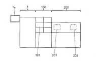
- FIG. 1 is a schematic front view showing a configuration example of an analysis system according to an embodiment of the present invention.
- This analysis system includes a pretreatment device 1, an LC (liquid chromatograph) 100, and an MS (mass spectrometry device) 200. Samples that have been pretreated by the pretreatment device 1 are sequentially introduced into the LC100 and the MS200. Analysis. That is, the analysis system according to the present embodiment has a configuration in which a liquid chromatograph mass spectrometer (LC / MS) is connected to the pretreatment device 1. However, the configuration is not limited to such a configuration, and the MS 200 may be omitted, so that the sample that has been subjected to the pre-processing by the pre-processing apparatus 1 may be introduced only into the LC 100. It may be configured to be introduced into the analysis apparatus.
- LC liquid chromatograph mass spectrometer
- the pretreatment device 1 performs various pretreatments such as sample dispensing, reagent dispensing, stirring, and filtration on biological samples such as whole blood, serum, filter paper blood, and urine.
- the sample extracted by these pretreatments is introduced into the LC 100 via the autosampler 101 provided in the LC 100.
- the LC 100 includes a column (not shown), and sample components separated in the process of passing the sample through the column are sequentially introduced into the MS 200.
- the MS 200 includes an ionization unit 201 that ionizes a sample introduced from the LC 100 and a mass analysis unit 202 that analyzes the ionized sample.
- the pre-processing device 1 is provided with an operation display unit 1a including a touch panel, for example.
- the analyst can perform input related to the operation of the preprocessing device 1 by operating the display screen of the operation display unit 1a, and can also provide information regarding the operation of the preprocessing device 1 displayed on the display screen of the operation display unit 1a. Can be confirmed.
- the configuration is not limited to the configuration in which the touch panel type operation display unit 1a is provided.
- the display unit configured by a liquid crystal display and the operation unit configured by operation keys or the like are provided separately. May be.
- FIG. 2 is a plan view showing a configuration example of the pretreatment device 1.
- a pretreatment kit consisting of a set of a separation container 50 and a collection container 54 is used for each sample, and pretreatment items (sample dispensing, reagent dispensing) set for each pretreatment kit are used. Note, stirring, filtration, etc.) are performed.
- the separation container 50 constitutes a pretreatment container into which a sample and a reagent are injected.
- the pretreatment apparatus 1 is provided with a plurality of treatment ports for executing each pretreatment item, and the pretreatment kit can be obtained by installing a pretreatment kit containing a sample in any of the treatment ports. A pre-processing item corresponding to each processing port is executed on the sample contained in the container.
- a filtration port 30, a dispensing port 32, a disposal port 34, a stirring port 36a, temperature control ports 38 and 40, a transfer port 43, a washing port 45, and the like are provided in association with each pretreatment item.
- Each of these processing ports constitutes a plurality of preprocessing units that respectively execute a plurality of types of preprocessing.
- the preprocessing item is a preprocessing item necessary for executing the analysis item designated by the analyst.
- the separation container 50 and the collection container 54 constituting the pretreatment kit are transported between the processing ports by the transport arm 24 as a transport unit.
- a holding portion 25 for holding the separation container 50 and the collection container 54 is formed on the distal end side of the transfer arm 24.
- the proximal end side of the transfer arm 24 is held so as to be rotatable about the vertical shaft 29.
- the transfer arm 24 extends in the horizontal direction, and rotates around the vertical axis 29 to move the holding unit 25 so as to draw an arcuate trajectory in the horizontal plane.
- Each processing port, which is the transfer destination of the separation container 50 and the collection container 54, and other ports are all provided on an arc-shaped track drawn by the holding unit 25.
- the sample is dispensed from the sample container 6 into the pretreatment kit.
- a plurality of sample containers 6 in which samples are stored can be installed in the sample installation unit 2, and samples are sequentially collected from each sample container 6 by a sampling arm 20 as a sampling unit.
- a plurality of sample racks 4 that hold a plurality of sample containers 6 are arranged in a ring shape in the sample placement unit 2.
- the sample placement unit 2 moves each sample rack 4 in the circumferential direction by rotating in a horizontal plane. Thereby, each sample container 6 can be sequentially moved to a predetermined sampling position.
- the sampling position is located on the trajectory of the sampling nozzle 20a provided at the tip of the sampling arm 20, and a sample is collected from the sample container 6 by the sampling nozzle 20a at the sampling position.
- the sampling arm 20 can rotate in a horizontal plane around a vertical shaft 22 provided on the base end side, and can move up and down along the vertical shaft 22 in the vertical direction.
- the sampling nozzle 20a is held vertically downward at the tip of the sampling arm 20, and according to the operation of the sampling arm 20, a circular orbital movement in the horizontal plane or vertical movement is performed. Is called.
- a dispensing port 32 is provided at a position on the orbit of the sampling nozzle 20a and on the orbit of the holding unit 25 of the transfer arm 24.
- the dispensing port 32 is a port for dispensing a sample to the unused separation container 50 from the sampling nozzle 20a.
- the unused separation container 50 is transported to the dispensing port 32 by the transport arm 24.
- a reagent installation unit 8 for installing the reagent container 10 is provided at the center of the sample installation unit 2 where the sample racks 4 are arranged in an annular shape.
- the reagent in the reagent container 10 installed in the reagent installation unit 8 is collected by the reagent arm 26.
- the base end portion of the reagent arm 26 is supported by a vertical shaft 29 that is common to the transfer arm 24, and can be rotated in a horizontal plane around the vertical shaft 29, and in the vertical direction along the vertical shaft 29. It can move up and down.
- a reagent addition nozzle 26 a is held vertically downward at the tip of the reagent arm 26, and the reagent addition nozzle 26 a is held in the horizontal plane in accordance with the operation of the reagent arm 26. The movement which draws the same circular arc-shaped orbit or the vertical movement in the vertical direction is performed.
- the reagent installing unit 8 can be rotated in a horizontal plane independently of the sample installing unit 2.
- a plurality of reagent containers 10 are arranged in an annular shape in the reagent installing unit 8, and each reagent container 10 moves in the circumferential direction as the reagent installing unit 8 rotates. Thereby, the desired reagent container 10 can be moved to a predetermined reagent collection position.
- the reagent collection position is located on the trajectory of the reagent addition nozzle 26a provided at the tip of the reagent arm 26, and the reagent is collected from the reagent container 10 by the reagent addition nozzle 26a at the reagent collection position.
- the reagent in the reagent container 10 is added to the sample in the separation container 50 by being sucked by the reagent addition nozzle 26a and then dispensed to the separation container 50 installed in the dispensing port 32. .
- the separation container 50 and the recovery container 54 are held by a container holding part 12 provided at a position different from the sample setting part 2 and the reagent setting part 8.
- a container holding part 12 In the container holding part 12, a plurality of (48 in the example of FIG. 2) holding a plurality of sets of pretreatment kits in a state where unused separation containers 50 and recovery containers 54 are stacked are arranged in an annular shape. Each of the positions 53 is held.
- the container holding unit 12 includes a rotating unit 14 that rotates in a horizontal plane, and a plurality of container racks 16 that can be attached to and detached from the rotating unit 14.
- Each container rack 16 can hold a plurality of pretreatment kits.
- the plurality of container racks 16 are arranged on the rotating unit 14 in an annular shape.
- An annular holding region for holding a plurality of pretreatment kits is formed by the plurality of container racks 16 arranged side by side in an annular shape.
- the rotating unit 14 displaces each container rack 16 in the circumferential direction of the holding region by rotating in a horizontal plane. Thereby, a plurality of pretreatment kits can be sequentially moved to a predetermined transport position.
- the transfer position is located on the track of the holding unit 25 provided at the tip of the transfer arm 24, and the separation container 50 or the collection container 54 is held by the holding unit 25 at the transfer position, and the transfer destination To the next port.
- the pretreatment kit (separation container 50 or collection container 54) held at each holding position 53 of the container holding unit 12 is unloaded from the transfer position in a certain order and used, so that the pretreatment is performed. It is done sequentially.
- the fixed order is not particularly limited. For example, the order of the plurality of container racks 16 is determined, and the order of the plurality of holding positions 53 is determined in each container rack 16. Therefore, after the pretreatment kits held at all the holding positions 53 of any one of the container racks 16 are unloaded, the pretreatment kits held at the holding positions 53 of the next container rack 16 are sequentially unloaded.
- the Rukoto Although not shown in FIG. 2, each holding position 53 is displayed with a number associated with the fixed order.
- each container rack 16 can be individually attached to and detached from the rotating unit 14. As a result, even when the separation container 50 or the collection container 54 held in any one of the container racks 16 is being processed, the other container rack 16 can be attached and detached to perform another operation. Therefore, the preprocessing efficiency can be improved.
- the separation container 50 and the collection container 54 are not limited to the configuration in which the separation container 50 and the collection container 54 are held by the container holding unit 12 via the container rack 16, and may be configured to be directly held by the container holding unit 12, for example. .
- the separation container 50 and the collection container 54 are not limited to the structure in which the separation container 50 and the collection container 54 are held by the container holding unit 12 in a state of being overlapped with each other. There may be.
- the plurality of container racks 16 is not limited to a configuration in which the plurality of container racks 16 are arranged in an annular shape, and for example, a configuration in which the plurality of container racks 16 are arranged in an arc shape may be employed. In this case, a plurality of separation containers 50 and recovery containers 54 are held in an arc-shaped holding area instead of an annular shape.
- an analyst can install a plurality of types (for example, two types) of separation containers 50 provided with separation layers having different separation performances. These separation containers 50 are selectively used according to the analysis item of the sample, and the separation container 50 corresponding to the analysis item designated by the analyst is selected from the container holding unit 12 and conveyed.
- the analysis item is a type of analysis that is subsequently performed using the sample that has been pre-processed by the pre-processing apparatus 1, for example, a type of analysis that is performed by the LC 100 or the MS 200.
- FIG. 3A is a side view showing a configuration example of the separation container 50.
- FIG. 3B is a plan view of the separation container 50 of FIG. 3A.
- FIG. 3C is a cross-sectional view showing the AA cross section of FIG. 3B.
- FIG. 4A is a side view showing a configuration example of the collection container 54.
- 4B is a plan view of the collection container 54 of FIG. 4A.
- 4C is a cross-sectional view showing a BB cross section of FIG. 4B.
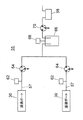
- FIG. 5 is a cross-sectional view showing the pretreatment kit in a state where the separation container 50 and the collection container 54 are overlaid.
- the separation container 50 is a cylindrical container having an internal space 50a for storing a sample and a reagent.
- a separation layer 52 is provided at the bottom of the internal space 50a.
- the separation layer 52 is a separation agent or a separation membrane having a function of selectively separating a specific component in a sample by allowing the sample to pass through and reacting with the specific component physically or chemically, for example.
- separating agent for example, ion exchange resin, silica gel, cellulose, activated carbon and the like can be used.
- the separation membrane include PTFE (polytetrafluoroethylene) membrane, nylon membrane, polypropylene membrane, PVDF (polyvinylidene fluoride) membrane, acrylic copolymer membrane, mixed cellulose membrane, nitrocellulose membrane, polyethersulfone membrane, An ion exchange membrane, a glass fiber membrane, etc. can be used.
- the deproteinization filter for removing the protein in the sample by filtration
- PTFE separation membrane
- an acrylic copolymer membrane or the like can be used as the deproteinization filter (separation membrane) for removing the protein in the sample by filtration
- a prefilter (not shown) may be provided above the separation layer 52 in order to prevent clogging of the deproteinization filter.
- a prefilter for example, a nylon film, a polypropylene film, a glass fiber film, or the like can be used.
- the prefilter is for removing insoluble substances and foreign matters having a relatively large particle diameter from the sample. This prefilter can prevent the deproteinization filter from being clogged with insoluble substances and foreign matters having a relatively large particle size.
- An opening 50b for injecting a sample or a reagent is formed on the upper surface of the separation container 50. Further, an extraction port 50 d for extracting the sample that has passed through the separation layer 52 is formed on the lower surface of the separation container 50. On the upper part of the outer peripheral surface of the separation container 50, a flange portion 50c for engaging the holding portion 25 of the transfer arm 24 is formed so as to protrude in the circumferential direction.
- a skirt portion 51 that contacts the edge of the filtration port 30 when the separation container 50 is accommodated in the filtration port 30 together with the recovery container 54 is provided at the center of the outer peripheral surface of the separation container 50.
- the skirt portion 51 protrudes in the circumferential direction from the outer peripheral surface of the separation container 50 and is formed in an L-shaped cross section so as to extend downward therefrom, thereby forming a certain space between the outer peripheral surface of the separation container 50. is doing.
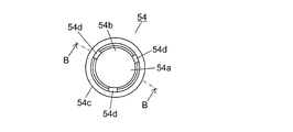
- the collection container 54 is a cylindrical container that houses the lower part of the separation container 50 and collects the sample extracted from the extraction port 50d of the separation container 50.
- An opening 54 b for inserting the lower part of the separation container 50 is formed on the upper surface of the collection container 54.
- an internal space 54 a that accommodates a portion of the separation container 50 below the skirt portion 51 is formed.
- a flange part 54 c for engaging the holding part 25 of the transfer arm 24 is formed on the upper part of the outer peripheral surface of the collection container 54 so as to protrude in the circumferential direction.
- the separation container 50 and the collection container 54 are overlapped as shown in FIG. 5, the upper part of the collection container 54 enters the inside of the skirt portion 51.
- the outer diameter of the separation container 50 is smaller than the inner diameter of the collection container 54. Thereby, a slight gap is formed between the outer peripheral surface of the separation container 50 accommodated in the internal space 54 a of the recovery container 54 and the inner peripheral surface of the recovery container 54.
- the separation container 50 and the recovery container 54 are installed in a state where the lower part of the separation container 50 is accommodated in the recovery container 54 (state in FIG. 5).
- notches 54d are formed on the upper edge of the collection container 54. Therefore, the separation container 50 and the collection container 54 are overlapped as shown in FIG. 5 so that the collection container 54 can be collected through the notch 54 even when the upper surface of the collection container 54 is in contact with the inner surface of the skirt portion 51.
- the inside and outside of the container 54 can be communicated.
- the number of notches 54d is not limited to three, and may be two or less, or four or more.
- the notch 54d not only the notch 54d but the structure in which the small hole was formed may be sufficient, for example.
- the filtration port 30 is provided inside the container holding part 12. That is, an annular or arc-shaped holding region is formed by the plurality of container racks 16 arranged side by side on the outer periphery of the filtration port 30, and the plurality of separation containers 50 and the collection containers 54 are held in the holding region. Yes.
- the holding region of the separation container 50 and the recovery container 54 is formed in an annular shape or an arc shape, and the installation space for the filtration port 30 is secured in the empty space in the center portion, thereby making the configuration more compact. Can do.
- the separation container 50 and the collection container 54 are held in the holding region in a stacked state, it is not necessary to provide the separation container 50 and the collection container 54 separately. Therefore, more separation containers 50 and recovery containers 54 can be held in a small holding area. Thereby, the holding
- the distance between the plurality of separation containers 50 and the collection containers 54 held in the holding area and the filtration port 30 can be relatively increased. Can be shortened. Thereby, since the time which conveys the separation container 50 and the collection
- the filtration port 30 constitutes a filtration unit that separates the sample by the separation layer 52 by applying pressure to the sample in the separation container 50.
- two filtration ports 30 are provided side by side on the track of the holding unit 25 of the transport arm 24.
- the separation container 50 and the collection container 54 are installed in each filtration port 30 in a state of being overlapped as shown in FIG. 5, and the sample separated by the separation layer 52 in the separation container 50 by the negative pressure is contained in the collection container 54. It has come to be collected.
- the separation container 50 and the collection container 54 are not limited to the structure in which the separation container 50 and the collection container 54 are installed in each filtration port 30 in a state of being overlapped with each other, but the structure in which the separation container 50 and the collection container 54 are individually installed. There may be. Further, the number of filtration ports 30 is not limited to two, and may be one or three or more.
- Three stirring ports 36 a are provided in the stirring unit 36 provided in the vicinity of the container holding unit 12, for example, on the track of the holding unit 25 of the transfer arm 24.
- the stirring unit 36 has a mechanism for individually operating each stirring port 36a in a horizontal plane. By such a mechanism, the sample in the separation container 50 arranged in each stirring port 36a can be stirred.
- the number of stirring ports 36a is not limited to three, and may be two or less, or four or more.
- the temperature control ports 38 and 40 are provided, for example, in a thermally conductive block whose temperature is controlled by a heater and a Peltier element, and the temperature of the separation container 50 or the recovery container 54 accommodated in the temperature control ports 38 and 40 is constant. Adjusted to temperature.
- the temperature control port 38 is for the separation container 50, and, for example, four temperature adjustment ports 38 are arranged side by side on the track of the holding unit 25 of the transfer arm 24.
- the temperature control port 40 is for the recovery container 54, and four temperature control ports 40 are arranged side by side on the track of the holding portion 25 of the transfer arm 24, for example, similarly to the temperature control port 38 for the separation container 50.
- the number of temperature control ports 38 and 40 is not limited to four, but may be three or less, or may be five or more.
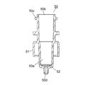
- FIG. 6A is a plan view showing a configuration example of the filtration port 30.
- 6B is a cross-sectional view showing the XX cross section of FIG. 6A.
- 6C is a cross-sectional view showing the YY cross section of FIG. 6A.
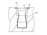
- FIG. 6D is a cross-sectional view showing a state where the pretreatment kit is installed in the filtration port 30.
- the filtration port 30 is composed of, for example, a recess, and the recess constitutes an installation space 30a for installing the pretreatment kit. That is, as shown in FIG. 6D, the separation container 50 and the collection container 54 conveyed from the container holding unit 12 by the conveyance arm 24 are installed in the installation space 30a so as to overlap each other. At this time, the collection container 54 is first accommodated in the installation space 30a, and then the lower part of the separation container 50 is accommodated in the internal space 54a of the recovery container 54.
- a holding member 31 that holds the collection container 54 so as to be sandwiched is provided.
- the holding member 31 is, for example, a U-shaped metal member that is open at the top, and constitutes two leaf springs in which two arms extending upward can be elastically displaced in the inner diameter direction of the filtration port 30. is doing.
- the two leaf spring portions of the holding member 31 have, for example, a curved shape or a bent shape that is recessed inward so that the interval between the upper end portion and the lower end portion is the narrowest.
- the distance between the two leaf spring portions is larger than the outer diameter of the recovery container 54 at the upper end and the lower end, and smaller than the outer diameter of the recovery container 54 at the narrowest distance.
- the two leaf springs of the holding member 31 are lowered as the collection container 54 descends. The portion is opened, and the collection container 54 is held in the installation space 30a by the elastic force.
- the collection container 54 is equally pressed from two opposing directions by the two leaf spring portions of the holding member 31 and is held in the central portion of the installation space 30a.
- the holding member 31 is fixed in the installation space 30a so that it does not float with the recovery container 54 when the recovery container 54 is taken out.
- a ring-shaped sealing member 60 having elasticity is provided at the edge of the upper opening of the filtration port 30.
- the sealing member 60 is fitted, for example, in a recess provided at the edge of the upper surface opening of the filtration port 30.
- the material of the sealing member 60 is an elastic material such as silicone rubber or EPDM (ethylene-propylene-diene rubber).
- the pressure reducing flow path 56 communicates with the installation space 30a from the bottom surface of the filtration port 30.
- a flow path 57 of the negative pressure load mechanism 55 is connected to the flow path 56.
- the negative pressure load mechanism 55 includes a vacuum pump, for example, and constitutes a negative pressure load portion that loads a negative pressure into the installation space 30a. If the inside of the installation space 30a is decompressed by the negative pressure load mechanism 55 in a state where the separation container 50 and the collection container 54 are accommodated in the filtration port 30, the inside of the installation space 30a becomes negative pressure.
- the internal space 54a of the recovery container 54 is formed through a notch 54d of the recovery container 54 and a gap between the inner peripheral surface of the recovery container 54 and the outer peripheral surface of the separation container 50.
- FIG. 7 is a schematic diagram showing a configuration example of the negative pressure load mechanism 55.
- the two filtration ports 30 are connected to a common vacuum tank 66.
- Each filtration port 30 and the vacuum tank 66 are connected by a flow path 57, and a pressure sensor 62 and a three-way valve 64 are provided in each flow path 57.
- the pressure in the installation space 30 a of each filtration port 30 is detected by each pressure sensor 62.
- Each three-way valve 64 is in a state in which the filtration port 30 and the vacuum tank 66 are connected, in a state in which the filtration port 30 side of the flow path 57 is opened to the atmosphere (state in FIG. 7), or in the flow path 57 It can switch to either the state which sealed the edge part by the side of the filtration port 30.
- a pressure sensor 68 is connected to the vacuum tank 66 and a vacuum pump 58 is connected via a three-way valve 70. Therefore, by switching the three-way valve 70, the vacuum pump 58 can be connected to the vacuum tank 66 as needed, and the pressure in the vacuum tank 66 can be adjusted.
- a pressure sensor 62 is connected between the filtration port 30 and the vacuum tank 66 to detect the pressure in the installation space 30 a of the filtration port 30.
- the value of is adjusted to be a predetermined value.
- the end of the flow path 57 on the filtration port 30 side is sealed.
- the installation space 30a of the filtration port 30 becomes a sealed system, and the sample is extracted by maintaining the reduced pressure state in the installation space 30a.
- the pretreatment apparatus 1 is provided with a sample transfer unit 42 for transferring the sample extracted in the collection container 54 to the autosampler 101 side.
- the sample transfer unit 42 includes a moving unit 44 that moves in one direction (the arrow direction in FIG. 2) in the horizontal plane, and a transfer port 43 for installing the collection container 54 is provided on the upper surface of the moving unit 44. It has been.
- the moving unit 44 moves by the operation of a drive mechanism having a rack and pinion mechanism, for example.
- the transfer port 43 is arranged on the track of the holding unit 25 of the transfer arm 24 (position indicated by a solid line in FIG. 2).
- the collection container 54 is installed in the transfer port 43 by the transfer arm 24 and the collection container 54 is collected from the transfer port 43.
- the moving unit 44 moves to the outside of the pretreatment apparatus 1.
- the transfer port 43 is disposed at a position adjacent to the autosampler 101 (a position indicated by a broken line in FIG. 2). In this state, the sample in the collection container 54 is inhaled by the sampling nozzle provided in the autosampler 101.
- the moving unit 44 When the sample inhalation by the autosampler 101 is completed, the moving unit 44 is returned to the original position (the position indicated by the solid line in FIG. 2), and the collection container 54 is collected by the transfer arm 24.
- the used collection container 54 is transported to the disposal port 34 by the transport arm 24 and discarded.
- the disposal port 34 is disposed in the vicinity of the dispensing port 32 on the track of the holding unit 25 of the transfer arm 24, and the used separation container 50 and the collection container 54 are discarded.
- a cleaning port 45 for cleaning the sampling nozzle 20a is provided on the orbit of the sampling nozzle 20a.
- a cleaning port for cleaning the reagent addition nozzle 26a is provided on the orbit of the reagent addition nozzle 26a.
- FIG. 8 is a block diagram showing an example of the electrical configuration of the analysis system.
- “port” refers to a plurality of types of ports such as the filtration port 30, the dispensing port 32, the agitation port 36a, the temperature control ports 38 and 40, and the transfer port 43 in which the separation container 50 or the recovery container 54 is installed. Means one of them.
- the operation of the negative pressure load mechanism 55 is controlled by the control unit 84.
- the control unit 84 includes, for example, a CPU (Central Processing ⁇ Unit), and when the CPU executes a program, the preprocessing unit 84a, the processing status management unit 84b, the random access unit 84c, the position setting reception unit 84d, and the number of containers are received. It functions as the means 84f and the display control means 84g.
- a CPU Central Processing ⁇ Unit
- an arithmetic processing device 90 configured by a personal computer (PC) or a dedicated computer is connected to the control unit 84, and the analyst can manage the preprocessing device 1 via the arithmetic processing device 90.
- the arithmetic processing unit 90 is connected not only to the preprocessing unit 1 but also to the LC 100 and the MS 200 into which the sample that has been pre-processed by the pre-processing unit 1 is introduced, the autosampler 101 that injects the sample into the LC 100, and the like.
- the arithmetic processing device 90 can automatically control these devices in conjunction with each other.
- a plurality of sample containers are installed in the sample installation unit 2, and the samples accommodated in these sample containers should be sequentially dispensed into the separation container 50 and executed on the samples.
- the separation container 50 is conveyed to the port corresponding to the pretreatment item.
- the preprocessing unit 84a executes a predetermined process at that port.
- the random access means 84c confirms the status of preprocessing at each port, and operates the transport arm 24 so as to transport the separation container 50 that has been preprocessed at that port to the port for performing the next preprocessing. To control. That is, the random access means 84c confirms the pretreatment item to be performed next for each sample, confirms the vacancy status of the port corresponding to the pretreatment item, and if there is a vacancy, the separation container containing the sample 50 or the collection container 54 is transported to the port. When there is no available port corresponding to the pretreatment item to be performed next for each sample, the random access means 84c sets the target separation container 50 or the recovery container 54 as the port as soon as the port is available. To transport.
- the processing status management means 84b manages the availability of each port and the processing status at each port.
- the availability of each port can be managed by storing in which port the separation container 50 or the collection container 54 is installed. Further, a sensor for detecting whether or not the separation container 50 or the collection container 54 is installed at each port may be provided, and the availability of each port may be managed based on a signal from the sensor.
- the processing status at each port can be managed by whether or not the time required for the pre-processing executed at the port has elapsed since the separation container 50 or the recovery container 54 was installed at the port.
- the status of processing at the transfer port 43 may be managed depending on whether or not a signal indicating that sample inhalation has ended is received from the autosampler 101 side.
- the random access means 84c is configured to be used in order from the port with the highest priority. For example, when both of the two filtration ports 30 are vacant when the sample is filtered, the collection container 54 is installed in the filtration port 30 having a high priority, and the separation container 50 is placed on the collection container 54. Is installed.
- the analyst When analyzing the sample, the analyst selects the analysis item of the sample by operating the operation display unit 1a.
- the analysis item is selected, for example, by the name of the component to be analyzed in LC100 or MS200. Then, the analyst can further set and select a pre-processing item necessary for executing the analysis item for the selected analysis item by further operating the operation display unit 1a. That is, for the selected analysis item, one or a plurality of arbitrary preprocessing items can be selected and set to be executed in the preprocessing device 1.
- the number of separation containers 50 and collection containers 54 scheduled to be used for analysis (scheduled number of use) is determined. Further, the analyst replenishes the container holding unit 12 with the separation container 50 and the collection container 54 as necessary. In the example of FIG. 2, the analyst starts analysis after the pretreatment kit (separation container 50 and collection container 54) is held in all 48 holding positions 53 in the container holding unit 12. A series of pretreatments using up to 48 pretreatment kits can be sequentially performed.
- the analyzer can set the holding position 53 of the pretreatment kit to be used first when analysis is started (when a series of pretreatments is started). It can be done.
- the position setting receiving unit 84d functions as a position setting receiving unit that receives the setting of the holding position 53 of the preprocessing kit to be used first when such an operation is performed.
- the analyst can input the number of pretreatment kits held in the container holding unit 12 by operating the operation display unit 1a.
- the container number receiving unit 84f functions as a container number receiving unit that receives an input of the number of pretreatment kits held in the container holding unit 12 when such an operation is performed.
- 48 holding positions 53 are provided in the container holding portion 12 as in the example of FIG. 2, when the analyst puts the pretreatment kit in all the holding positions 53, the container holding portion Therefore, “48” is input as the number of pretreatment kits held in 12.
- the preprocessing unit 84a, the processing status management unit 84b, and the random access unit 84c constitute a preprocessing execution unit 84e.
- the preprocessing execution unit 84e is configured based on various settings including settings received by the position setting receiving unit 84d and the container number receiving unit 84f, the preprocessing unit configured by each port, the sampling arm 20, the transfer arm 24, and the like.
- the reagent arm 26 and the like are controlled.
- the preprocessing execution unit 84e performs control so that a plurality of types of preprocessing set for different samples are executed in parallel.
- the separation container 50 or the recovery container 54 in which different samples are accommodated is sequentially transferred to each port corresponding to a plurality of types of pretreatment, and the pretreatment for each sample is executed in parallel.
- the preprocessing execution unit 84e Based on the management by the processing status management unit 84b, the preprocessing execution unit 84e performs control so that different samples are not preprocessed simultaneously on the same port.
- each port forms an individual preprocessing unit.
- an arbitrary separation container 50 or a collection container 54 is sequentially transported to a plurality of ports (pretreatment units) by the transport arm 24, and preprocessing is performed in parallel at each port. Can be made. Thereby, even if it takes a long time to pre-process any sample, it is possible to advance the pre-processing of another sample first, and it is possible to suppress generation of useless waiting time.
- pre-processing since multiple types of pre-processing and parameters for each pre-processing can be set for each sample, a wide variety of pre-processing can be executed for each sample. Even in such a case, an arbitrary separation container 50 or collection container 54 can be sequentially transported to a plurality of ports by the transport arm 24 to execute pretreatment, and the same port can be used for different samples. Since the pre-processing is controlled so as not to be executed simultaneously, the degree of freedom in setting the pre-processing is high and the pre-processing efficiency can be improved.
- the display control means 84g functions as a display control unit for controlling display on the operation display unit 1a. Under the control of the display control means 84g, various display screens can be switched and displayed on the operation display unit 1a. In the present embodiment, a device status screen for displaying information related to the operation of the preprocessing device 1, a condition setting screen for accepting setting of conditions, and the like are displayed on the operation display unit 1a by the control of the display control unit 84g. The The contents of the settings received by the position setting receiving means 84d and the container number receiving means 84f are also displayed on the operation display unit 1a under the control of the display control means 84g.
- the position information storage unit 86 is connected to the control unit 84.
- the position information storage unit 86 is configured by, for example, a hard disk or a RAM (Random Access Memory), and stores information related to the holding position 53 of the preprocessing kit. Specifically, when the analysis ends (when a series of preprocessing ends), the last used preprocessing kit holding position 53 is stored in the position information storage unit 86.
- FIG. 9A is a diagram showing an example of a device status screen 300 displayed on the operation display unit 1a.
- the apparatus status screen 300 is a screen for displaying information related to the operation of the pretreatment apparatus 1.
- the execution status of the pretreatment on the sample in the pretreatment apparatus 1 is displayed.
- a symbol image 301 representing the sample placement unit 2 of the pretreatment apparatus 1 is displayed, and each sample container 6 is associated with the holding position of the sample container 6 in the sample placement unit 2 in the symbol image 301.
- the execution status of the pretreatment for the sample is displayed.
- the symbol image 301 is divided into a plurality of arc-shaped regions in association with a plurality of sample racks 4 arranged in an annular shape, like the actual sample placement unit 2, and a sample container is provided in each arc-shaped region.
- a plurality of switching areas 302 corresponding to 6 are provided.
- the display mode for example, color
- the execution status of the pretreatment for the sample in each sample container 6 is displayed according to the display mode. Yes.
- sample placement unit 2 is not limited to a configuration in which the sample container 6 is placed divided into a plurality of sample racks 4.
- the execution status of the pretreatment for the sample “Awaiting analysis” where the pretreatment has not yet been executed, “In analysis” where the pretreatment has started but the analysis result has not yet been obtained, and the analysis data is obtained normally. Examples thereof include “normal end” obtained, “abnormal end” in which an abnormality occurred during preprocessing or analysis, and “data abnormality” in which the obtained analysis data is abnormal.
- the switching area 302 corresponding to the ten sample containers 6 is switched to the “analysis waiting” display mode, and the switching area 302 corresponding to the two sample containers 6 is switched to the “analyzing” display mode.
- the switching area 302 corresponding to one sample container 6 is switched to the “data abnormality” display mode.
- the operation state of the preprocessing device 1 is displayed at the center of the symbol image 301.
- “analyzing” is displayed because the preprocessing device 1 is operating.
- “stopping” is displayed.
- a preprocessing process display area 303 for displaying a preprocessing process that has been executed for each sample under analysis is provided.
- a preprocessing information display area 304 for displaying information related to the operation of the preprocessing apparatus 1 an LC information display area 305 for displaying information related to the operation of the LC100,
- an MS information display area 306 for displaying information related to the operation of the MS 200 is provided.
- the information displayed in the pretreatment information display area 304 includes the connection state 341 of the pretreatment device 1 with respect to the arithmetic processing device 90, the pressure 342 in the filtration port 30, the number of sets of the separation container 50 and the collection container 54 (the remaining number, 343), temperature 344 of each part of the pretreatment device 1 (such as the reagent cooling unit and the temperature control ports 38 and 40), and the state of the pure water tank for storing water used during washing and dispensing 345, pump state 346 for degassing water used during washing and dispensing, waste liquid tank state 347 for draining water used during washing, used separation container 50 and recovery container 54 are discarded Examples thereof include a state 348 of a waste box to be used, a state 349 of a pump for sending out water to be used at the time of washing and dispensing. At least one of these pieces of information may be displayed in the preprocessing information display area 304, other various parameters set as conditions when the preprocessing device 1 operates, and other information on the preprocessing device 1
- Examples of information displayed in the LC information display area 305 include the connection state 351 of the LC 100 to the arithmetic processing unit 90, the pressure 352 of the pump that sends the sample and the mobile phase to the column, the temperature 353 of the oven that heats the column, etc. Can do.
- the LC information display area 305 at least one of these pieces of information may be displayed, and other various parameters set as conditions when the LC 100 operates, the states of other parts of the LC 100, and the like are displayed. May be. For example, even if the autosampler needle lowering stroke, sample suction speed, needle washing time, pump mobile phase flow rate, mobile phase mixing ratio, column oven upper limit set temperature, etc. are displayed in the LC information display area 305 in the LC 100 Good.
- the pressure, flow rate, and oven temperature of the mobile phase of the pump are preferably displayed as parameters having a great influence on the analysis data.
- Information displayed in the MS information display area 306 includes the connection state 361 of the MS 200 with respect to the arithmetic processing unit 90, the gas flow rate 362 used in the MS 200, the temperature 363 of each part of the MS 200, the degree of vacuum 364 of each part of the MS 200, and the like. It can be illustrated.
- the MS information display area 306 at least one of these pieces of information may be displayed, other various parameters set as conditions when the MS 200 operates, the states of other parts of the MS 200, and the like are displayed. May be.
- MS information nebulizer gas flow rate, drying gas flow rate, interface voltage / current, DL (desolvent tube) temperature, heat block temperature, detector voltage, vacuum degree of each vacuum chamber, CID gas pressure, etc. It may be displayed at 306.
- the nebulizer gas flow rate, the drying gas flow rate, the DL temperature, the heat block temperature, and the degree of vacuum are preferably displayed as parameters that have a large influence on the analysis data.
- At least one of the pre-processing information display area 304, the LC information display area 305, and the MS information display area 306 is provided with abnormal display areas 340, 350, and 360 for displaying abnormal information.
- the pretreatment information display area 304 for example, the connection state 341 of the pretreatment device 1 with respect to the arithmetic processing device 90, the state 345 of a pure water tank for storing water used at the time of washing and dispensing, the time of washing and dispensing
- An abnormality display area 340 is provided in association with a state 349 of a pump for sending out water to be used for cleaning and dispensing.
- an abnormality display area 350 is provided in association with the connection state 351 of the LC 100 with respect to the arithmetic processing unit 90.
- an abnormality display area 360 is provided in association with the connection state 361 of the MS 200 with respect to the arithmetic processing unit 90.
- Each abnormality display area 340, 350, 360 is for displaying the abnormality information when the corresponding state is abnormal.
- the abnormality display areas 340, 350, and 360 have different colors depending on whether the state is normal or abnormal. By displaying, an abnormality is displayed.
- the state of the LC 100 or the MS 200 in which the abnormality information is displayed in the abnormality display areas 350 and 360 is not limited to the connection state 351 and 361, and abnormality can be displayed for other various states.
- the display of the abnormality information in each abnormality display area 340, 350, 360 is not limited to switching by color, and can be performed by various other modes such as switching of lighting or blinking.
- a part of the apparatus status screen 300 (for example, the uppermost part) includes a start key 307 selected when the analysis is started, a pause key 308 selected when the analysis is paused, and an emergency with an alarm in an emergency.
- a screen switching key 310 selected when switching the display of the operation display unit 1a from the apparatus status screen 300 to the condition setting screen is displayed. The analyst can easily start an analysis in response to an instruction from the preprocessing device 1 by selecting a start key 307 after selecting an analysis method registered in advance.
- FIG. 9B is a diagram illustrating an example of a screen displayed on the operation display unit 1a when the start key 307 is selected.
- the holding position 53 of the pretreatment kit to be used first can be set from the plurality of holding positions 53 of the container holding unit 12, and the start key 370 is selected after making the setting. By doing so, the analysis can be started by first using the pretreatment kit at the set holding position 53.
- the screen shown in FIG. 9B includes, in addition to the start key 370, a container number input area 371, a container supply setting area 372, a next use position display area 373, a planned use number display area 374, and the like.
- the container number input area 371 the number of pretreatment kits held in the container holding unit 12 is input.
- 60 pretreatment kits equal in number to the sample containers 6 are also provided in the container holding unit 12. Can be held.
- the analyst replenishes the container holding unit 12 with the pretreatment kit when starting the analysis and the pretreatment kit is held in all the holding positions 53, the analyst enters the container number input area 371. “60” which is the number of all the holding positions 53 is input.
- the container supply setting area 372 includes a check box 375 for selecting a predetermined holding position 53 as a leading holding position 53a (see FIG. 2).
- the holding position 53 of the preprocessing kit to be used first is determined as the first holding position 53a.
- the next holding position 53 is determined as the holding position 53 of the pretreatment kit to be used first.
- the position setting receiving unit 84d first sets a certain holding position 53 (first holding position 53a) among the plurality of holding positions 53.
- the setting is accepted as the holding position 53 of the pretreatment kit used for the above.
- the pre-processing that the position setting receiving unit 84d uses first based on the information stored in the position information storage unit 86.
- the setting of the holding position 53 of the kit is accepted.
- the configuration may be such that an arbitrary holding position 53 can be set as the holding position 53 of the pretreatment kit to be used first.
- the holding position 53 of the preprocessing kit to be used first is determined based on the information stored in the position information storage unit 86. It will be.
- the analyst when the analyst replenishes the container holding unit 12 with the pretreatment kit when starting the analysis and the pretreatment kit is held in all the holding positions 53, the analyst selects the check box 375. After selection, the start key 370 is selected. As a result, the pretreatment is carried out from the container holding unit 12 in order from the pretreatment kit held at the leading holding position 53a.
- the start key 370 can be selected without selecting the check box 375 when starting the next analysis.
- the number of remaining pretreatment kits is calculated and displayed in the container number input area 371, and the analyst selects only the start key 370 without performing the setting operation for the container number input area 371.
- the number displayed in the container number input area 371 can be input as the number of pretreatment kits held in the container holding unit 12.
- next use position display area 373 the holding position 53 of the pretreatment kit that is used first when the start key 370 is selected to start the analysis is displayed. Therefore, when the check box 375 in the container supply setting area 372 is selected, “1” is displayed in the next use position display area 373. On the other hand, when the check box 375 is not selected, a number corresponding to the holding position 53 of the pretreatment kit to be used first is displayed based on the information stored in the position information storage unit 86.
- the number of pretreatment kits to be used when the start key 370 is selected and analysis is started is displayed.
- the number displayed in the planned use number display area 374 needs to be equal to or less than the number displayed in the container number input area 371.
- the number displayed in the container number input area 371 may be smaller than the number displayed in the planned use number display area 374.
- the display control unit 84g functions as a notification processing unit for performing the notification.
- the plurality of holding positions 53 are held at a fixed holding position 53 (for example, the first holding position 53a). Not only the pretreatment kit but also a pretreatment kit held at another holding position 53 can be used first to execute a series of pretreatments. Therefore, if the holding position 53 where the pretreatment kit is held is set as the holding position 53 of the pretreatment kit to be used first, a series of pretreatments can be started without performing the work of replenishing the pretreatment kit. It becomes possible. Thereby, pre-processing can be started with a simple operation.
- the pre-processing last used in the previous pre-processing is not selected.
- the holding position 53 where the pretreatment kit is held for example, the holding position 53 next to the last used preprocessing kit holding position 53
- the preprocessing can be started with a simpler operation.
- a certain holding position 53 among the plurality of holding positions 53 is selected.
- the first holding position 53a can be determined as the holding position 53 of the pretreatment kit to be used first.
- the pretreatment kit held at any holding position 53 may be used first, so the pretreatment kit held at the fixed holding position 53 is used first. By doing so, the operation at the time of pre-processing can be simplified.
- the number of pretreatment kits held in the container holding unit 12 after replenishment when the series of pretreatments is started after performing the work of replenishing the pretreatment kits is input to the container number input area. 371 can be entered.
- the number of pretreatment kits that can be used in a series of pretreatments can be ascertained in the pretreatment device 1, so that appropriate processing can be performed according to the number.
- the analyst who has confirmed the notification can prevent the start of a series of pretreatments in a state where the number of pretreatment kits to be used is insufficient by performing an operation of replenishing the pretreatment kits. it can.
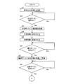
- FIG. 10A and FIG. 10B are flowcharts showing an example of the operation of the preprocessing device 1.
- FIG. 10A and FIG. 10B show only the flow of pretreatment for one sample, and this pretreatment operation is executed concurrently and independently with the pretreatment operation of other samples.
- Pre-processing is performed in parallel and independently means that a separation container 50 or a collection container 54 containing another sample is transported while pre-processing is being performed for each sample at each port. This means that the sample is transported to another port by the arm 24 and the pretreatment of the sample is performed independently.
- step S1 the analysis items designated in advance by the analyst are checked for the sample (step S1), and the pre-processing items necessary for executing the analysis items are determined. Then, it is confirmed whether or not the dispensing port 32 is vacant. If the dispensing port 32 is vacant (Yes in step S2), an unused separation container 50 for storing the sample is transferred by the transfer arm 24. It is taken out from the container holding part 12 and installed in the dispensing port 32 (step S3). At this time, the separation container 50 and the collection container 54 are installed in the container holding unit 12 in a state where they are overlapped (the state shown in FIG. 5). Hold and transport to dispensing port 32.
- the sample is dispensed by the sampling nozzle 20a into the separation container 50 in the dispensing port 32 (step S4).
- the sampling nozzle 20a that dispenses the sample into the separation container 50 is prepared for the dispensing of the next sample after being washed in the washing port 45.
- a reagent according to the pretreatment to be performed on the sample is dispensed from the reagent container 10 by the reagent addition nozzle 26a (step S5). Note that the dispensing of the reagent into the separation container 50 may be performed before the dispensing of the sample.
- a reagent dispensing port for dispensing the reagent is provided at a position different from the dispensing port 32, and the separation container 50 is transported to the reagent dispensing port by the transport arm 24, and the reagent dispensing is performed.
- the configuration may be such that reagent is dispensed at the service port.
- Step S6 After the sample and the reagent are dispensed into the separation container 50 in this way, the empty state of the stirring port 36a is confirmed (step S6). If the agitation port 36a is empty (Yes in step S6), the separation container 50 in the dispensing port 32 is conveyed to the vacant agitation port 36a by the conveying arm 24 and agitation processing is performed ( Step S7). This agitation process is performed for a predetermined period of time, whereby the sample and the reagent in the separation container 50 are mixed.
- the availability of the filtration port 30 is confirmed (step S8). If the filtration port 30 is empty (Yes in step S8), the collection container 54 is transported to the filtration port 30 by the transport arm 24 (step S9). At this time, the collection container 54 installed in the filtration port 30 is a collection container 54 that forms a pair with the separation container 50 being stirred at the stirring port 36a, and is installed in a state of being overlapped with the separation container 50 in the container holding unit 12. It is the collection container 54 that had been stored. During the stirring process, another separation container 50 and recovery container 54 can be transported by the transport arm 24.
- Step S10 the separation container 50 is transported from the stirring port 36a to the filtration port 30 by the transport arm 24, and the separation container 50 is installed on the collection container 54 in the filtration port 30 as shown in FIG. 6D.
- Step S10 the separation container 50 is conveyed until the lower end of the skirt portion 51 of the separation container 50 is slightly lower (for example, about 0.1 mm) than the height of the upper surface of the sealing member 60 provided around the filtration port 30.
- the arm 24 is pressed toward the installation space 30a. Thereby, since the sealing member 60 is crushed by the lower end of the skirt part 51, the airtightness between the lower end of the skirt part 51 and the sealing member 60 improves.
- a predetermined negative pressure is applied to the installation space 30 a of the filtration port 30 in which the separation container 50 and the recovery container 54 are installed by the negative pressure load mechanism 55.
- the sample in the separation container 50 is filtered and the sample is extracted into the collection container 54 (step S11).
- the separation arm 50 and the recovery container 54 can be transported by the transport arm 24.
- a temperature adjustment process is incorporated in which the sample in the separation container 50 is maintained at a constant temperature for a certain period of time after the sample in the separation container 50 is stirred. There is also. In that case, after the stirring process is completed, the empty state of the temperature control port 38 is confirmed. If there is an empty space, the separation container 50 is transferred to the empty temperature control port 38. Then, after a certain time has elapsed, the separation container 50 in the temperature control port 38 is conveyed to the filtration port 30 and installed on the recovery container 54 in the filtration port 30.
- the three-way valve 64 (see FIG. 7) is switched to set the inside of the installation space 30a of the filtration port 30 to atmospheric pressure. Then, the used separation container 50 is taken out from the filtration port 30 by the holding unit 25 of the transfer arm 24 and discarded to the disposal port 34 (step S12).
- the transfer port 43 is empty (Yes in step S13), the collection container 54 in the filtration port 30 is transferred to the sample transfer unit 42 by the transfer arm 24 and transferred. Installed on port 43. Then, the moving unit 44 moves to a position on the side of the autosampler 101 arranged adjacently (a position indicated by a broken line in FIG. 2), whereby the collection container 54 is transferred to the side of the autosampler 101 (step S14). . On the autosampler 101 side, the sample is sucked into the collection container 54 transferred from the sample transfer unit 42 by the sampling nozzle.
- the moving unit 44 stops at the position on the autosampler 101 side until the sample inhalation in the autosampler 101 is completed.
- the signal indicating that the sample inhalation is completed is received from the autosampler 101 (Yes in step S15)
- To the position (the position indicated by the solid line in FIG. 2).
- the used collection container 54 is collected from the transfer port 43 by the transfer arm 24 and discarded to the discard port 34 (step S16).
- a temperature control process for maintaining the sample extracted in the collection container 54 at a constant temperature for a fixed time after the sample is filtered.
- the empty state of the temperature control port 40 is confirmed, and if there is an empty space, the collection container 54 is transported to the empty temperature control port 40. Then, after a predetermined time has elapsed, the collection container 54 in the temperature control port 40 is transported to the transfer port 43, and the sample is transferred.
- the container rack 16 may be configured to hold the pretreatment kit in one row, or may be configured to hold in three or more rows.
- the plurality of holding positions 53 are not limited to the configuration arranged in an annular shape, and may be a configuration arranged in another manner such as an arc shape or a linear shape.
- the configuration in which the sample in the separation container 50 is separated by setting the inside of the installation space 30a of the filtration port 30 to a negative pressure has been described.
- the configuration is not limited to such a configuration, and the configuration may be such that the sample in the separation container 50 is separated by pressurizing the inside of the separation container 50.
- control unit 84 and the arithmetic processing unit 90 of the preprocessing device 1 are not limited to the configurations provided separately, and may be configured such that the operation of the entire analysis system is controlled by one control unit. That is, the configuration may be such that the arithmetic processing device 90 is omitted, and information is directly transmitted and received between the preprocessing device 1 and the LC 100 or the MS 200.
- the pretreatment container into which the sample is injected is not limited to the separation container 50 that constitutes the pretreatment kit together with the recovery container 54, and may be a separation container used alone or a container other than the separation container. There may be. Further, the pretreatment container is not limited to a configuration in which the pretreatment container is unloaded from each holding position 53 of the container rack 16 and used, for example, a configuration in which the pretreatment container is used while being held at each holding position 53. Also good.
Abstract
Provided are a pretreatment device with which it is possible to begin pretreatment via a simple operation, and an analysis system provided with the pretreatment device. A container holding unit 12 holds pretreatment containers, into each of which a sample is injected. A pretreatment unit sequentially carries out a pretreatment by using, in a fixed order, the pretreatment containers held in holding positions of the container holding unit 12. If a series of pretreatments using multiple pretreatment containers is begun by the pretreatment unit, a position setting receiving means 84d receives a setting regarding which holding position from among the holding positions of the pretreatment container is to be used first.
Description
本発明は、試料に対して前処理を実行する前処理装置に関するものである。
The present invention relates to a pretreatment apparatus that performs pretreatment on a sample.
例えば全血、血清、濾紙血、尿などの生体由来の試料に含まれる成分の分析を行う際、試料に対して前処理装置により前処理を行った後、分析を行う場合がある。前処理としては、分析に不要な特定成分を試料から除去して必要成分を抽出する処理や、抽出された試料を濃縮又は乾固させる処理などを例示することができる。このような前処理を自動的に実行する前処理装置として、従来から種々の構成が提案されている(例えば、下記特許文献1参照)。
For example, when analyzing components contained in a sample derived from a living body such as whole blood, serum, filter paper blood, and urine, the sample may be analyzed after being pretreated by a pretreatment device. Examples of the pretreatment include a process of removing a specific component unnecessary for analysis from a sample and extracting a necessary component, and a process of concentrating or drying the extracted sample. Conventionally, various configurations have been proposed as preprocessing devices that automatically execute such preprocessing (see, for example, Patent Document 1 below).
例えば特許文献1では、試料を通過させて試料中の特定成分を分離させる分離剤を有するカートリッジ(分離容器)が、共通の搬送機構により複数保持されて搬送される構成が開示されている。複数のカートリッジは、所定位置に設けられた圧力負荷機構に対して搬送機構により順次搬送され、当該圧力負荷機構において圧力が負荷されることにより試料の抽出が行われる。カートリッジからの抽出液を受ける複数の受皿容器(回収容器)は、カートリッジの下方において、カートリッジとは別の搬送機構によって搬送されることにより、試料の抽出が連続的に行われる。
For example, Patent Document 1 discloses a configuration in which a plurality of cartridges (separation containers) having a separating agent that allows a sample to pass through and separates a specific component in the sample are held and conveyed by a common conveyance mechanism. The plurality of cartridges are sequentially transported by a transport mechanism to a pressure load mechanism provided at a predetermined position, and a sample is extracted by applying pressure to the pressure load mechanism. The plurality of tray containers (collection containers) that receive the extraction liquid from the cartridge are transported by a transport mechanism separate from the cartridge below the cartridge, whereby the sample is continuously extracted.
この種の前処理装置では、試料が注入される前処理容器(カートリッジ)が装置内の複数の保持位置に保持されており、これらの前処理容器を一定の順序で使用することにより前処理が順次行われる。使用された前処理容器は自動で廃棄され、分析終了時には、全ての保持位置の前処理容器が廃棄された状態、又は、一部の保持位置にのみ前処理容器が保持された状態となる。
In this type of pretreatment apparatus, pretreatment containers (cartridges) into which samples are injected are held at a plurality of holding positions in the apparatus, and pretreatment can be performed by using these pretreatment containers in a certain order. It is done sequentially. The used pretreatment container is automatically discarded, and at the end of the analysis, the pretreatment containers at all holding positions are discarded, or the pretreatment containers are held only at some holding positions.
次の分析を開始する際には、前処理容器が保持されていない保持位置に新たな前処理容器が補充されることにより、全ての保持位置に前処理容器が保持された状態とされる。その後、分析を開始する操作が行われると、複数の保持位置のうち一定の保持位置(先頭の保持位置)に保持されている前処理容器から順に使用され、一連の前処理が実行される。
When starting the next analysis, a new pretreatment container is replenished to a holding position where the pretreatment container is not held, so that the pretreatment containers are held at all holding positions. Thereafter, when an operation for starting the analysis is performed, the pretreatment containers that are held in a certain holding position (first holding position) among the plurality of holding positions are used in order, and a series of preprocessing is executed.
このように、従来の前処理装置では、分析を開始する際に、前処理容器を補充する作業を行ってから分析を開始する必要がある。したがって、例えば比較的少数の前処理容器を使用して分析を行った後、次に行う分析に使用する前処理容器の数が十分に足りている場合であっても、前処理容器を補充した上で分析を開始させなければならず、作業が煩雑であった。
Thus, in the conventional pretreatment apparatus, when the analysis is started, it is necessary to start the analysis after performing the work of replenishing the pretreatment container. Thus, for example, after performing analysis using a relatively small number of pretreatment containers, the pretreatment containers were replenished even when the number of pretreatment containers used for the next analysis was sufficient. The analysis had to be started above, and the work was complicated.
本発明は、上記実情に鑑みてなされたものであり、簡単な作業で前処理を開始させることができる前処理装置及びこれを備えた分析システムを提供することを目的とする。
The present invention has been made in view of the above circumstances, and an object of the present invention is to provide a preprocessing apparatus capable of starting preprocessing by a simple operation and an analysis system including the preprocessing apparatus.
本発明に係る前処理装置は、試料に対して前処理を実行する前処理装置であって、容器保持部と、前処理部と、位置設定受付部とを備える。前記容器保持部は、複数の保持位置に、それぞれ試料が注入される前処理容器を保持する。前記前処理部は、前記容器保持部の各保持位置に保持されている前処理容器を一定の順序で使用することにより前処理を順次行う。前記位置設定受付部は、複数の前処理容器を使用した一連の前処理が前記前処理部により開始される場合に、前記複数の保持位置の中から最初に使用する前処理容器の保持位置の設定を受け付ける。
The pretreatment apparatus according to the present invention is a pretreatment apparatus that performs pretreatment on a sample, and includes a container holding unit, a pretreatment unit, and a position setting receiving unit. The container holding unit holds a pretreatment container into which a sample is injected at a plurality of holding positions. The pretreatment unit sequentially performs pretreatment by using the pretreatment containers held at the holding positions of the container holding unit in a predetermined order. The position setting reception unit is configured to determine a holding position of a pretreatment container to be used first from among the plurality of holding positions when a series of preprocessing using a plurality of pretreatment containers is started by the preprocessing unit. Accept settings.
このような構成によれば、複数の前処理容器を使用した一連の前処理が開始される場合に、複数の保持位置のうち一定の保持位置に保持されている前処理容器に限らず、他の保持位置に保持されている前処理容器を最初に使用して、一連の前処理を実行することができる。したがって、前処理容器が保持されている保持位置を最初に使用する前処理容器の保持位置として設定すれば、前処理容器を補充する作業を行うことなく一連の前処理を開始させることが可能になる。これにより、簡単な作業で前処理を開始させることができる。
According to such a configuration, when a series of pretreatments using a plurality of pretreatment containers is started, not only a pretreatment container held at a fixed holding position among a plurality of holding positions, A series of pretreatments can be performed using the pretreatment container held in the holding position first. Therefore, if the holding position where the pretreatment container is held is set as the holding position of the pretreatment container to be used first, a series of pretreatments can be started without performing the work of replenishing the pretreatment container. Become. Thereby, pre-processing can be started with a simple operation.
前記前処理装置は、前記前処理部による一連の前処理が終了したときに、最後に使用された前処理容器の保持位置に関する情報を記憶する位置情報記憶部をさらに備えていてもよい。この場合、前記位置設定受付部は、前記位置情報記憶部に記憶されている情報に基づいて前記最初に使用する前処理容器の保持位置を決定するか否かの設定を受け付けてもよい。
The pre-processing apparatus may further include a position information storage unit that stores information related to the last used pre-processing container holding position when a series of pre-processing by the pre-processing unit is completed. In this case, the position setting receiving unit may receive a setting as to whether or not to determine a holding position of the pretreatment container to be used first based on information stored in the position information storage unit.
このような構成によれば、複数の前処理容器を使用した一連の前処理が開始される場合に、前回の前処理の際に最後に使用された前処理容器の保持位置に関する情報に基づいて、前処理容器が保持されている保持位置を最初に使用する前処理容器の保持位置として自動で設定することが可能になる。したがって、前処理容器を補充する作業を行うことなく一連の前処理を開始させる場合などに、より簡単な作業で前処理を開始させることができる。
According to such a configuration, when a series of pretreatments using a plurality of pretreatment containers is started, based on the information on the holding position of the pretreatment container used last in the previous pretreatment. The holding position where the pretreatment container is held can be automatically set as the holding position of the pretreatment container to be used first. Therefore, when starting a series of pre-processing without performing the operation | work which replenishes a pre-processing container, a pre-processing can be started with a simpler operation | work.
前記位置設定受付部は、前記複数の保持位置のうち一定の保持位置を前記最初に使用する前処理容器の保持位置に決定するか否かの設定を受け付けてもよい。
The position setting reception unit may receive a setting as to whether or not to determine a predetermined holding position among the plurality of holding positions as a holding position of the pretreatment container to be used first.
このような構成によれば、前処理容器を補充する作業を行ってから一連の前処理を開始させる場合などに、複数の保持位置のうち一定の保持位置を最初に使用する前処理容器の保持位置に決定することができる。前処理容器を補充した場合には、いずれの保持位置に保持されている前処理容器を最初に使用してもよいため、一定の保持位置に保持されている前処理容器を最初に使用することにより、前処理時の動作を簡略化することができる。
According to such a configuration, when a series of pretreatment is started after performing an operation of replenishing the pretreatment container, the pretreatment container that first uses a certain holding position among the plurality of holding positions is held. The position can be determined. When the pretreatment container is replenished, the pretreatment container held in any holding position may be used first, so the pretreatment container held in a certain holding position should be used first. As a result, the operation during pre-processing can be simplified.
前記前処理装置は、前記容器保持部に保持されている前処理容器の数の入力を受け付ける容器数受付部をさらに備えていてもよい。
The pre-processing apparatus may further include a container number receiving unit that receives an input of the number of pre-processing containers held in the container holding unit.
このような構成によれば、前処理容器を補充する作業を行ってから一連の前処理を開始させる場合などに、補充後に容器保持部に保持されている前処理容器の数を入力することができる。これにより、一連の前処理で使用可能な前処理容器の数を前処理装置内で把握することができるため、その数に応じて適切な処理を行うことができる。
According to such a configuration, the number of pretreatment containers held in the container holding unit after refilling can be input when a series of pretreatments is started after performing the work of replenishing the pretreatment containers. it can. Thereby, since the number of pretreatment containers that can be used in a series of pretreatments can be grasped in the pretreatment apparatus, appropriate treatment can be performed according to the number.
前記前処理装置は、前記容器数受付部により入力が受け付けられた前処理容器の数が、前記前処理部により開始される一連の前処理に使用する前処理容器の数よりも少ない場合に、その旨を報知する報知処理部をさらに備えていてもよい。
When the number of pretreatment containers whose input is received by the container number receiving unit is smaller than the number of pretreatment containers used for a series of pretreatments started by the pretreatment unit, You may further provide the alerting | reporting process part which alert | reports that.
このような構成によれば、使用可能な前処理容器の数が、実際の一連の前処理に使用する前処理容器の数よりも少ない場合に、その旨が報知される。これにより、報知を確認した分析者は、前処理容器を補充する作業を行うことにより、使用する前処理容器の数が足りない状態のまま一連の前処理が開始されるのを防止することができる。
According to such a configuration, when the number of usable pretreatment containers is smaller than the number of pretreatment containers used for the actual series of pretreatments, the fact is notified. Thus, the analyst who has confirmed the notification can prevent the start of a series of pretreatments in a state where the number of pretreatment vessels to be used is insufficient by performing an operation of replenishing the pretreatment vessels. it can.
本発明に係る分析システムは、前記前処理装置と、分析装置と、制御部とを備える。前記分析装置には、前記前処理装置において前処理が実行された試料が導入される。前記制御部は、前記前処理装置及び前記分析装置を連動させて自動制御する。
The analysis system according to the present invention includes the pretreatment device, the analysis device, and a control unit. A sample that has been pretreated in the pretreatment device is introduced into the analysis device. The control unit automatically controls the pretreatment device and the analysis device in conjunction with each other.
本発明によれば、前処理容器を補充する作業を行うことなく一連の前処理を開始させることが可能になるため、簡単な作業で前処理を開始させることができる。
According to the present invention, it is possible to start a series of pretreatments without performing the work of replenishing the pretreatment container, so that the pretreatment can be started with a simple work.
図1は、本発明の一実施形態に係る分析システムの構成例を示す概略正面図である。この分析システムは、前処理装置1、LC(液体クロマトグラフ)100及びMS(質量分析装置)200を備えており、前処理装置1により前処理を実行した試料が、LC100及びMS200に順次導入されて分析が行われる。すなわち、本実施形態に係る分析システムは、前処理装置1に液体クロマトグラフ質量分析装置(LC/MS)が接続された構成となっている。ただし、このような構成に限らず、MS200が省略されることにより、前処理装置1により前処理を実行した試料が、LC100にのみに導入されるような構成であってもよいし、他の分析装置に導入されるような構成であってもよい。
FIG. 1 is a schematic front view showing a configuration example of an analysis system according to an embodiment of the present invention. This analysis system includes a pretreatment device 1, an LC (liquid chromatograph) 100, and an MS (mass spectrometry device) 200. Samples that have been pretreated by the pretreatment device 1 are sequentially introduced into the LC100 and the MS200. Analysis. That is, the analysis system according to the present embodiment has a configuration in which a liquid chromatograph mass spectrometer (LC / MS) is connected to the pretreatment device 1. However, the configuration is not limited to such a configuration, and the MS 200 may be omitted, so that the sample that has been subjected to the pre-processing by the pre-processing apparatus 1 may be introduced only into the LC 100. It may be configured to be introduced into the analysis apparatus.
前処理装置1は、例えば全血、血清、濾紙血、尿などの生体由来の試料に対して、試料分注、試薬分注、攪拌、濾過といった各種の前処理を行う。これらの前処理により抽出された試料は、LC100に備えられたオートサンプラ101を介してLC100に導入される。LC100には、カラム(図示せず)が備えられており、当該カラム内を試料が通過する過程で分離された試料成分が、MS200に順次導入される。MS200は、LC100から導入された試料をイオン化するイオン化部201と、イオン化された試料を分析する質量分析部202とを備えている。
The pretreatment device 1 performs various pretreatments such as sample dispensing, reagent dispensing, stirring, and filtration on biological samples such as whole blood, serum, filter paper blood, and urine. The sample extracted by these pretreatments is introduced into the LC 100 via the autosampler 101 provided in the LC 100. The LC 100 includes a column (not shown), and sample components separated in the process of passing the sample through the column are sequentially introduced into the MS 200. The MS 200 includes an ionization unit 201 that ionizes a sample introduced from the LC 100 and a mass analysis unit 202 that analyzes the ionized sample.
前処理装置1には、例えばタッチパネルを含む操作表示部1aが備えられている。分析者は、操作表示部1aの表示画面に対する操作により、前処理装置1の動作に関する入力を行うことができるとともに、操作表示部1aの表示画面に表示された前処理装置1の動作に関する情報を確認することができる。ただし、タッチパネル式の操作表示部1aが設けられた構成に限らず、例えば液晶表示器により構成される表示部と、操作キーなどにより構成される操作部とが、別々に設けられた構成であってもよい。
The pre-processing device 1 is provided with an operation display unit 1a including a touch panel, for example. The analyst can perform input related to the operation of the preprocessing device 1 by operating the display screen of the operation display unit 1a, and can also provide information regarding the operation of the preprocessing device 1 displayed on the display screen of the operation display unit 1a. Can be confirmed. However, the configuration is not limited to the configuration in which the touch panel type operation display unit 1a is provided. For example, the display unit configured by a liquid crystal display and the operation unit configured by operation keys or the like are provided separately. May be.
図2は、前処理装置1の構成例を示す平面図である。この前処理装置1では、分離容器50と回収容器54の組からなる前処理キットを試料ごとに1組用いて、各前処理キットに対して設定された前処理項目(試料分注、試薬分注、攪拌、濾過など)が実行される。分離容器50は、試料及び試薬が注入される前処理容器を構成している。前処理装置1には、各前処理項目を実行するための複数の処理ポートが設けられており、試料が収容された前処理キットをいずれかの処理ポートに設置することで、その前処理キットに収容されている試料に対して、各処理ポートに対応する前処理項目が実行されるようになっている。
FIG. 2 is a plan view showing a configuration example of the pretreatment device 1. In this pretreatment apparatus 1, a pretreatment kit consisting of a set of a separation container 50 and a collection container 54 is used for each sample, and pretreatment items (sample dispensing, reagent dispensing) set for each pretreatment kit are used. Note, stirring, filtration, etc.) are performed. The separation container 50 constitutes a pretreatment container into which a sample and a reagent are injected. The pretreatment apparatus 1 is provided with a plurality of treatment ports for executing each pretreatment item, and the pretreatment kit can be obtained by installing a pretreatment kit containing a sample in any of the treatment ports. A pre-processing item corresponding to each processing port is executed on the sample contained in the container.
処理ポートとしては、各前処理項目に対応付けて、濾過ポート30、分注ポート32、廃棄ポート34、攪拌ポート36a、温調ポート38,40、転送ポート43及び洗浄ポート45などが設けられている。これらの各処理ポートは、複数種類の前処理をそれぞれ実行する複数の前処理部を構成している。ここで、前処理項目とは、分析者が指定した分析項目を実行するために必要な前処理の項目である。
As processing ports, a filtration port 30, a dispensing port 32, a disposal port 34, a stirring port 36a, temperature control ports 38 and 40, a transfer port 43, a washing port 45, and the like are provided in association with each pretreatment item. Yes. Each of these processing ports constitutes a plurality of preprocessing units that respectively execute a plurality of types of preprocessing. Here, the preprocessing item is a preprocessing item necessary for executing the analysis item designated by the analyst.
前処理キットを構成する分離容器50及び回収容器54は、搬送部としての搬送アーム24によって各処理ポート間で搬送される。搬送アーム24の先端側には、分離容器50及び回収容器54を保持するための保持部25が形成されている。搬送アーム24の基端部側は、鉛直軸29を中心に回転可能に保持されている。搬送アーム24は水平方向に延びており、鉛直軸29を中心に回転することにより、保持部25が水平面内で円弧状の軌道を描くように移動する。分離容器50及び回収容器54の搬送先である各処理ポートや、その他のポートは、全て保持部25が描く円弧状の軌道上に設けられている。
The separation container 50 and the collection container 54 constituting the pretreatment kit are transported between the processing ports by the transport arm 24 as a transport unit. A holding portion 25 for holding the separation container 50 and the collection container 54 is formed on the distal end side of the transfer arm 24. The proximal end side of the transfer arm 24 is held so as to be rotatable about the vertical shaft 29. The transfer arm 24 extends in the horizontal direction, and rotates around the vertical axis 29 to move the holding unit 25 so as to draw an arcuate trajectory in the horizontal plane. Each processing port, which is the transfer destination of the separation container 50 and the collection container 54, and other ports are all provided on an arc-shaped track drawn by the holding unit 25.
前処理キットには、試料容器6から試料が分注される。試料が収容された試料容器6は、試料設置部2に複数設置することができ、サンプリング部としてのサンプリングアーム20により各試料容器6から試料が順次採取される。試料設置部2には、複数の試料容器6を保持するサンプルラック4が、円環状に並べて複数設置される。試料設置部2は、水平面内で回転することにより、各サンプルラック4を周方向に移動させる。これにより、所定のサンプリング位置に各試料容器6を順次移動させることができる。ここで、サンプリング位置は、サンプリングアーム20の先端部に設けられたサンプリングノズル20aの軌道上に位置しており、当該サンプリング位置においてサンプリングノズル20aにより試料容器6から試料が採取される。
The sample is dispensed from the sample container 6 into the pretreatment kit. A plurality of sample containers 6 in which samples are stored can be installed in the sample installation unit 2, and samples are sequentially collected from each sample container 6 by a sampling arm 20 as a sampling unit. A plurality of sample racks 4 that hold a plurality of sample containers 6 are arranged in a ring shape in the sample placement unit 2. The sample placement unit 2 moves each sample rack 4 in the circumferential direction by rotating in a horizontal plane. Thereby, each sample container 6 can be sequentially moved to a predetermined sampling position. Here, the sampling position is located on the trajectory of the sampling nozzle 20a provided at the tip of the sampling arm 20, and a sample is collected from the sample container 6 by the sampling nozzle 20a at the sampling position.
サンプリングアーム20は、基端部側に設けられた鉛直軸22を中心に水平面内で回転可能であるとともに、鉛直軸22に沿って鉛直方向に上下動可能である。サンプリングノズル20aは、サンプリングアーム20の先端部において鉛直下方に向かって保持されており、サンプリングアーム20の動作に応じて、水平面内で円弧状の軌道を描く移動又は鉛直方向への上下動が行われる。
The sampling arm 20 can rotate in a horizontal plane around a vertical shaft 22 provided on the base end side, and can move up and down along the vertical shaft 22 in the vertical direction. The sampling nozzle 20a is held vertically downward at the tip of the sampling arm 20, and according to the operation of the sampling arm 20, a circular orbital movement in the horizontal plane or vertical movement is performed. Is called.
サンプリングノズル20aの軌道上で、かつ搬送アーム24の保持部25の軌道上となる位置には、分注ポート32が設けられている。分注ポート32は、未使用の分離容器50に対してサンプリングノズル20aから試料を分注するためのポートである。未使用の分離容器50は、搬送アーム24によって分注ポート32に搬送される。
A dispensing port 32 is provided at a position on the orbit of the sampling nozzle 20a and on the orbit of the holding unit 25 of the transfer arm 24. The dispensing port 32 is a port for dispensing a sample to the unused separation container 50 from the sampling nozzle 20a. The unused separation container 50 is transported to the dispensing port 32 by the transport arm 24.
サンプルラック4が円環状に並べて配置された試料設置部2の中央部には、試薬容器10を設置するための試薬設置部8が設けられている。試薬設置部8に設置された試薬容器10内の試薬は、試薬アーム26によって採取される。試薬アーム26は、その基端部が搬送アーム24と共通の鉛直軸29によって支持されており、当該鉛直軸29を中心に水平面内で回転可能であるとともに、鉛直軸29に沿って鉛直方向に上下動可能である。試薬アーム26の先端部には、試薬添加ノズル26aが鉛直下方に向かって保持されており、当該試薬添加ノズル26aは、試薬アーム26の動作に応じて、水平面内で搬送アーム24の保持部25と同一の円弧状の軌道を描く移動又は鉛直方向への上下動が行われる。
A reagent installation unit 8 for installing the reagent container 10 is provided at the center of the sample installation unit 2 where the sample racks 4 are arranged in an annular shape. The reagent in the reagent container 10 installed in the reagent installation unit 8 is collected by the reagent arm 26. The base end portion of the reagent arm 26 is supported by a vertical shaft 29 that is common to the transfer arm 24, and can be rotated in a horizontal plane around the vertical shaft 29, and in the vertical direction along the vertical shaft 29. It can move up and down. A reagent addition nozzle 26 a is held vertically downward at the tip of the reagent arm 26, and the reagent addition nozzle 26 a is held in the horizontal plane in accordance with the operation of the reagent arm 26. The movement which draws the same circular arc-shaped orbit or the vertical movement in the vertical direction is performed.
試薬設置部8は、試料設置部2とは独立して水平面内で回転可能となっている。試薬設置部8には、複数の試薬容器10が円環状に並べて配置され、試薬設置部8が回転することによって各試薬容器10が周方向に移動する。これにより、所定の試薬採取位置に所望の試薬容器10を移動させることができる。ここで、試薬採取位置は、試薬アーム26の先端部に設けられた試薬添加ノズル26aの軌道上に位置しており、当該試薬採取位置において試薬添加ノズル26aにより試薬容器10から試薬が採取される。試薬容器10内の試薬は、試薬添加ノズル26aにより吸入された後、分注ポート32に設置された分離容器50に対して分注されることにより、当該分離容器50内の試料に添加される。
The reagent installing unit 8 can be rotated in a horizontal plane independently of the sample installing unit 2. A plurality of reagent containers 10 are arranged in an annular shape in the reagent installing unit 8, and each reagent container 10 moves in the circumferential direction as the reagent installing unit 8 rotates. Thereby, the desired reagent container 10 can be moved to a predetermined reagent collection position. Here, the reagent collection position is located on the trajectory of the reagent addition nozzle 26a provided at the tip of the reagent arm 26, and the reagent is collected from the reagent container 10 by the reagent addition nozzle 26a at the reagent collection position. . The reagent in the reagent container 10 is added to the sample in the separation container 50 by being sucked by the reagent addition nozzle 26a and then dispensed to the separation container 50 installed in the dispensing port 32. .
分離容器50及び回収容器54は、試料設置部2や試薬設置部8とは異なる位置に設けられた容器保持部12により保持されている。容器保持部12には、未使用の分離容器50及び回収容器54が重ねられた状態の複数組の前処理キットが、円環状に並べて配置された複数(図2の例では48個)の保持位置53にそれぞれ保持される。容器保持部12には、水平面内で回転する回転部14と、当該回転部14に対して着脱可能な複数の容器ラック16とが備えられている。
The separation container 50 and the recovery container 54 are held by a container holding part 12 provided at a position different from the sample setting part 2 and the reagent setting part 8. In the container holding part 12, a plurality of (48 in the example of FIG. 2) holding a plurality of sets of pretreatment kits in a state where unused separation containers 50 and recovery containers 54 are stacked are arranged in an annular shape. Each of the positions 53 is held. The container holding unit 12 includes a rotating unit 14 that rotates in a horizontal plane, and a plurality of container racks 16 that can be attached to and detached from the rotating unit 14.
各容器ラック16には、複数の前処理キットを保持することができる。複数の容器ラック16は、回転部14上に円環状に並べて設置される。円環状に並べて配置された複数の容器ラック16により、複数の前処理キットを保持する円環状の保持領域が形成される。回転部14は、水平面内で回転することにより、各容器ラック16を保持領域の周方向に変位させる。これにより、複数の前処理キットを所定の搬送位置に順次移動させることができる。ここで、搬送位置は、搬送アーム24の先端部に設けられた保持部25の軌道上に位置しており、当該搬送位置において保持部25により分離容器50又は回収容器54が保持され、搬送先のポートへと搬送される。
Each container rack 16 can hold a plurality of pretreatment kits. The plurality of container racks 16 are arranged on the rotating unit 14 in an annular shape. An annular holding region for holding a plurality of pretreatment kits is formed by the plurality of container racks 16 arranged side by side in an annular shape. The rotating unit 14 displaces each container rack 16 in the circumferential direction of the holding region by rotating in a horizontal plane. Thereby, a plurality of pretreatment kits can be sequentially moved to a predetermined transport position. Here, the transfer position is located on the track of the holding unit 25 provided at the tip of the transfer arm 24, and the separation container 50 or the collection container 54 is held by the holding unit 25 at the transfer position, and the transfer destination To the next port.
すなわち、容器保持部12の各保持位置53に保持されている前処理キット(分離容器50又は回収容器54)が、それぞれ搬送位置から一定の順序で搬出されて使用されることにより、前処理が順次行われる。上記一定の順序は、特に限定されるものではないが、例えば複数の容器ラック16の順序が定められているとともに、各容器ラック16において複数の保持位置53の順序が定められている。したがって、いずれかの容器ラック16の全ての保持位置53に保持されている前処理キットが搬出された後に、次の容器ラック16の各保持位置53に保持されている前処理キットが順次搬出されることとなる。図2では図示しないが、各保持位置53には、上記一定の順序に従って番号が対応付けて表示されている。
That is, the pretreatment kit (separation container 50 or collection container 54) held at each holding position 53 of the container holding unit 12 is unloaded from the transfer position in a certain order and used, so that the pretreatment is performed. It is done sequentially. The fixed order is not particularly limited. For example, the order of the plurality of container racks 16 is determined, and the order of the plurality of holding positions 53 is determined in each container rack 16. Therefore, after the pretreatment kits held at all the holding positions 53 of any one of the container racks 16 are unloaded, the pretreatment kits held at the holding positions 53 of the next container rack 16 are sequentially unloaded. The Rukoto. Although not shown in FIG. 2, each holding position 53 is displayed with a number associated with the fixed order.
このように、複数の容器ラック16に分割して前処理キットを保持することにより、各容器ラック16を回転部14に対して個別に着脱することが可能になる。これにより、いずれかの容器ラック16に保持された分離容器50又は回収容器54に対する処理が行われている場合であっても、他の容器ラック16を着脱して別の作業を行うことができるため、前処理効率を向上させることができる。
Thus, by dividing the container rack 16 into a plurality of container racks 16 and holding the pretreatment kit, each container rack 16 can be individually attached to and detached from the rotating unit 14. As a result, even when the separation container 50 or the collection container 54 held in any one of the container racks 16 is being processed, the other container rack 16 can be attached and detached to perform another operation. Therefore, the preprocessing efficiency can be improved.
ただし、分離容器50及び回収容器54は、容器ラック16を介して容器保持部12により保持されるような構成に限らず、例えば容器保持部12に直接保持されるような構成であってもよい。また、分離容器50及び回収容器54は、互いに重ね合せられた状態で容器保持部12により保持されるような構成に限らず、分離容器50及び回収容器54が個別に保持されるような構成であってもよい。さらに、複数の容器ラック16は、円環状に並べて配置されるような構成に限らず、例えば円弧状に並べて配置されるような構成であってもよい。この場合は、円環状ではなく、円弧状の保持領域に複数の分離容器50及び回収容器54が保持される。
However, the separation container 50 and the collection container 54 are not limited to the configuration in which the separation container 50 and the collection container 54 are held by the container holding unit 12 via the container rack 16, and may be configured to be directly held by the container holding unit 12, for example. . Further, the separation container 50 and the collection container 54 are not limited to the structure in which the separation container 50 and the collection container 54 are held by the container holding unit 12 in a state of being overlapped with each other. There may be. Further, the plurality of container racks 16 is not limited to a configuration in which the plurality of container racks 16 are arranged in an annular shape, and for example, a configuration in which the plurality of container racks 16 are arranged in an arc shape may be employed. In this case, a plurality of separation containers 50 and recovery containers 54 are held in an arc-shaped holding area instead of an annular shape.
容器保持部12には、異なる分離性能を有する分離層が設けられた複数種類(例えば2種類)の分離容器50を分析者が設置しておくことができる。これらの分離容器50は、試料の分析項目に応じて使い分けられ、分析者によって指定された分析項目に応じた分離容器50が容器保持部12から選択されて搬送される。ここで、分析項目とは、前処理装置1で前処理が施された試料を用いて引き続き行われる分析の種類であり、例えばLC100又はMS200により実行される分析の種類である。
In the container holding part 12, an analyst can install a plurality of types (for example, two types) of separation containers 50 provided with separation layers having different separation performances. These separation containers 50 are selectively used according to the analysis item of the sample, and the separation container 50 corresponding to the analysis item designated by the analyst is selected from the container holding unit 12 and conveyed. Here, the analysis item is a type of analysis that is subsequently performed using the sample that has been pre-processed by the pre-processing apparatus 1, for example, a type of analysis that is performed by the LC 100 or the MS 200.
図3Aは、分離容器50の構成例を示す側面図である。図3Bは、図3Aの分離容器50の平面図である。図3Cは、図3BのA-A断面を示す断面図である。図4Aは、回収容器54の構成例を示す側面図である。図4Bは、図4Aの回収容器54の平面図である。図4Cは、図4BのB-B断面を示す断面図である。図5は、分離容器50及び回収容器54が重ね合せられた状態の前処理キットを示す断面図である。
FIG. 3A is a side view showing a configuration example of the separation container 50. FIG. 3B is a plan view of the separation container 50 of FIG. 3A. FIG. 3C is a cross-sectional view showing the AA cross section of FIG. 3B. FIG. 4A is a side view showing a configuration example of the collection container 54. 4B is a plan view of the collection container 54 of FIG. 4A. 4C is a cross-sectional view showing a BB cross section of FIG. 4B. FIG. 5 is a cross-sectional view showing the pretreatment kit in a state where the separation container 50 and the collection container 54 are overlaid.
分離容器50は、図3A~図3Cに示すように、試料や試薬を収容する内部空間50aを有する円筒状の容器である。内部空間50aの底部には、分離層52が設けられている。分離層52とは、例えば試料を通過させて特定成分と物理的又は化学的に反応することで、試料中の特定成分を選択的に分離させる機能を有する分離剤又は分離膜である。
As shown in FIGS. 3A to 3C, the separation container 50 is a cylindrical container having an internal space 50a for storing a sample and a reagent. A separation layer 52 is provided at the bottom of the internal space 50a. The separation layer 52 is a separation agent or a separation membrane having a function of selectively separating a specific component in a sample by allowing the sample to pass through and reacting with the specific component physically or chemically, for example.
分離層52を構成する分離剤としては、例えばイオン交換樹脂、シリカゲル、セルロース、活性炭などを用いることができる。また、分離膜としては、例えばPTFE(ポリテトラフルオロエチレン)膜、ナイロン膜、ポリプロピレン膜、PVDF(ポリフッ化ビニリデン)膜、アクリル共重合体膜、混合セルロース膜、ニトロセルロース膜、ポリエーテルスルホン膜、イオン交換膜、グラスファイバー膜などを用いることができる。
As the separating agent constituting the separating layer 52, for example, ion exchange resin, silica gel, cellulose, activated carbon and the like can be used. Examples of the separation membrane include PTFE (polytetrafluoroethylene) membrane, nylon membrane, polypropylene membrane, PVDF (polyvinylidene fluoride) membrane, acrylic copolymer membrane, mixed cellulose membrane, nitrocellulose membrane, polyethersulfone membrane, An ion exchange membrane, a glass fiber membrane, etc. can be used.
試料中の蛋白質を濾過によって取り除くための除蛋白フィルタ(分離膜)としては、PTFE、アクリル共重合体膜などを用いることができる。この場合、除蛋白フィルタの目詰まりを防止するために、分離層52の上側にプレフィルタ(図示せず)を設けてもよい。このようなプレフィルタとしては、例えばナイロン膜、ポリプロピレン膜、グラスファイバー膜などを用いることができる。プレフィルタは、試料中から粒径の比較的大きい不溶物質や異物を取り除くためのものである。このプレフィルタにより、除蛋白フィルタが粒径の比較的大きい不溶物質や異物によって目詰まりするのを防止することができる。
As the deproteinization filter (separation membrane) for removing the protein in the sample by filtration, PTFE, an acrylic copolymer membrane or the like can be used. In this case, a prefilter (not shown) may be provided above the separation layer 52 in order to prevent clogging of the deproteinization filter. As such a prefilter, for example, a nylon film, a polypropylene film, a glass fiber film, or the like can be used. The prefilter is for removing insoluble substances and foreign matters having a relatively large particle diameter from the sample. This prefilter can prevent the deproteinization filter from being clogged with insoluble substances and foreign matters having a relatively large particle size.
分離容器50の上面には、試料や試薬を注入するための開口50bが形成されている。また、分離容器50の下面には、分離層52を通過した試料を抽出するための抽出口50dが形成されている。分離容器50の外周面の上部には、搬送アーム24の保持部25を係合させるための鍔部50cが周方向に突出するように形成されている。
An opening 50b for injecting a sample or a reagent is formed on the upper surface of the separation container 50. Further, an extraction port 50 d for extracting the sample that has passed through the separation layer 52 is formed on the lower surface of the separation container 50. On the upper part of the outer peripheral surface of the separation container 50, a flange portion 50c for engaging the holding portion 25 of the transfer arm 24 is formed so as to protrude in the circumferential direction.
分離容器50の外周面の中央部には、当該分離容器50が回収容器54とともに濾過ポート30に収容されたときに濾過ポート30の縁に接触するスカート部51が設けられている。スカート部51は、分離容器50の外周面から周方向に突出し、そこから下方に延びるように断面L字状に形成されることにより、分離容器50の外周面との間に一定の空間を形成している。
A skirt portion 51 that contacts the edge of the filtration port 30 when the separation container 50 is accommodated in the filtration port 30 together with the recovery container 54 is provided at the center of the outer peripheral surface of the separation container 50. The skirt portion 51 protrudes in the circumferential direction from the outer peripheral surface of the separation container 50 and is formed in an L-shaped cross section so as to extend downward therefrom, thereby forming a certain space between the outer peripheral surface of the separation container 50. is doing.
回収容器54は、図4A~図4C及び図5に示すように、分離容器50の下部を収容し、分離容器50の抽出口50dから抽出された試料を回収する円筒状の容器である。回収容器54の上面には、分離容器50の下部を挿入させる開口54bが形成されている。回収容器54の内部には、分離容器50におけるスカート部51よりも下側の部分を収容する内部空間54aが形成されている。回収容器54の外周面の上部には、分離容器50と同様に、搬送アーム24の保持部25を係合させるための鍔部54cが周方向に突出するように形成されている。
4A to 4C and FIG. 5, the collection container 54 is a cylindrical container that houses the lower part of the separation container 50 and collects the sample extracted from the extraction port 50d of the separation container 50. An opening 54 b for inserting the lower part of the separation container 50 is formed on the upper surface of the collection container 54. Inside the collection container 54, an internal space 54 a that accommodates a portion of the separation container 50 below the skirt portion 51 is formed. Similar to the separation container 50, a flange part 54 c for engaging the holding part 25 of the transfer arm 24 is formed on the upper part of the outer peripheral surface of the collection container 54 so as to protrude in the circumferential direction.
図5のように分離容器50及び回収容器54が重ね合せられた状態では、回収容器54の上部がスカート部51の内側に入り込む。分離容器50の外径は、回収容器54の内径よりも小さく形成されている。これにより、回収容器54の内部空間54aに収容された分離容器50の外周面と、回収容器54の内周面との間に、僅かな隙間が形成される。容器保持部12には、分離容器50の下部が回収容器54内に収容された状態(図5の状態)で、分離容器50及び回収容器54が設置される。
In the state where the separation container 50 and the collection container 54 are overlapped as shown in FIG. 5, the upper part of the collection container 54 enters the inside of the skirt portion 51. The outer diameter of the separation container 50 is smaller than the inner diameter of the collection container 54. Thereby, a slight gap is formed between the outer peripheral surface of the separation container 50 accommodated in the internal space 54 a of the recovery container 54 and the inner peripheral surface of the recovery container 54. In the container holding unit 12, the separation container 50 and the recovery container 54 are installed in a state where the lower part of the separation container 50 is accommodated in the recovery container 54 (state in FIG. 5).
回収容器54の上面の縁には、3つの切欠き54dが形成されている。したがって、図5のように分離容器50及び回収容器54が重ね合せられることにより、回収容器54の上面がスカート部51の内面に当接した状態であっても、切欠き54を介して、回収容器54の内側と外側とを連通させることができる。ただし、切欠き54dの数は、3つに限らず、2つ以下であってもよいし、4つ以上であってもよい。また、切欠き54dに限らず、例えば小穴が形成された構成などであってもよい。
Three notches 54d are formed on the upper edge of the collection container 54. Therefore, the separation container 50 and the collection container 54 are overlapped as shown in FIG. 5 so that the collection container 54 can be collected through the notch 54 even when the upper surface of the collection container 54 is in contact with the inner surface of the skirt portion 51. The inside and outside of the container 54 can be communicated. However, the number of notches 54d is not limited to three, and may be two or less, or four or more. Moreover, not only the notch 54d but the structure in which the small hole was formed may be sufficient, for example.
再び図2を参照すると、濾過ポート30は、容器保持部12の内側に設けられている。すなわち、濾過ポート30の外周に並べて配置された複数の容器ラック16により、円環状又は円弧状の保持領域が形成されており、当該保持領域に複数の分離容器50及び回収容器54が保持されている。このように、分離容器50及び回収容器54の保持領域が円環状又は円弧状に形成され、その中央部の空きスペースに濾過ポート30の設置スペースを確保することによって、よりコンパクトな構成とすることができる。
Referring to FIG. 2 again, the filtration port 30 is provided inside the container holding part 12. That is, an annular or arc-shaped holding region is formed by the plurality of container racks 16 arranged side by side on the outer periphery of the filtration port 30, and the plurality of separation containers 50 and the collection containers 54 are held in the holding region. Yes. As described above, the holding region of the separation container 50 and the recovery container 54 is formed in an annular shape or an arc shape, and the installation space for the filtration port 30 is secured in the empty space in the center portion, thereby making the configuration more compact. Can do.
特に、本実施形態では、分離容器50及び回収容器54が重ねられた状態で保持領域に保持されるため、分離容器50及び回収容器54の保持領域を別々に設ける必要がない。したがって、より多くの分離容器50及び回収容器54を小さい保持領域で保持することができる。これにより、分離容器50及び回収容器54の保持領域を小さくすることができ、さらにコンパクトな構成とすることができる。
In particular, in the present embodiment, since the separation container 50 and the collection container 54 are held in the holding region in a stacked state, it is not necessary to provide the separation container 50 and the collection container 54 separately. Therefore, more separation containers 50 and recovery containers 54 can be held in a small holding area. Thereby, the holding | maintenance area | region of the separation container 50 and the collection | recovery container 54 can be made small, and it can be set as a more compact structure.
また、円環状又は円弧状に形成された保持領域の中央部に濾過ポート30を設けることにより、保持領域に保持されている複数の分離容器50及び回収容器54と濾過ポート30の距離を比較的短くすることができる。これにより、分離容器50及び回収容器54を濾過ポート30に搬送する時間を短縮することができるため、前処理効率を向上させることができる。
Further, by providing the filtration port 30 at the center of the holding area formed in an annular shape or an arc shape, the distance between the plurality of separation containers 50 and the collection containers 54 held in the holding area and the filtration port 30 can be relatively increased. Can be shortened. Thereby, since the time which conveys the separation container 50 and the collection | recovery container 54 to the filtration port 30 can be shortened, pre-processing efficiency can be improved.
濾過ポート30は、分離容器50内の試料に圧力を付与することにより分離層52で試料を分離させる濾過部を構成している。本実施形態では、例えば2つの濾過ポート30が搬送アーム24の保持部25の軌道上に並べて設けられている。分離容器50及び回収容器54は、図5のように重ね合せられた状態で各濾過ポート30に設置され、負圧によって分離容器50内の分離層52で分離された試料が、回収容器54内に回収されるようになっている。ただし、分離容器50及び回収容器54は、互いに重ね合せられた状態で各濾過ポート30に設置されるような構成に限らず、分離容器50及び回収容器54が個別に設置されるような構成であってもよい。また、濾過ポート30の数は、2つに限らず、1つであってもよいし、3つ以上であってもよい。
The filtration port 30 constitutes a filtration unit that separates the sample by the separation layer 52 by applying pressure to the sample in the separation container 50. In the present embodiment, for example, two filtration ports 30 are provided side by side on the track of the holding unit 25 of the transport arm 24. The separation container 50 and the collection container 54 are installed in each filtration port 30 in a state of being overlapped as shown in FIG. 5, and the sample separated by the separation layer 52 in the separation container 50 by the negative pressure is contained in the collection container 54. It has come to be collected. However, the separation container 50 and the collection container 54 are not limited to the structure in which the separation container 50 and the collection container 54 are installed in each filtration port 30 in a state of being overlapped with each other, but the structure in which the separation container 50 and the collection container 54 are individually installed. There may be. Further, the number of filtration ports 30 is not limited to two, and may be one or three or more.
攪拌ポート36aは、容器保持部12の近傍に設けられた攪拌部36に、例えば搬送アーム24の保持部25の軌道上に並べて3つ設けられている。攪拌部36は、各攪拌ポート36aを個別に水平面内で周期的に動作させる機構を有している。このような機構により、各攪拌ポート36aに配置された分離容器50内の試料を攪拌することができる。ただし、攪拌ポート36aの数は、3つに限らず、2つ以下であってもよいし、4つ以上であってもよい。
Three stirring ports 36 a are provided in the stirring unit 36 provided in the vicinity of the container holding unit 12, for example, on the track of the holding unit 25 of the transfer arm 24. The stirring unit 36 has a mechanism for individually operating each stirring port 36a in a horizontal plane. By such a mechanism, the sample in the separation container 50 arranged in each stirring port 36a can be stirred. However, the number of stirring ports 36a is not limited to three, and may be two or less, or four or more.
温調ポート38,40は、例えばヒータとペルチェ素子により温度制御された熱伝導性のブロックに設けられており、温調ポート38,40に収容された分離容器50又は回収容器54の温度が一定温度に調節される。温調ポート38は、分離容器50用であり、例えば搬送アーム24の保持部25の軌道上に並べて4つ配置されている。温調ポート40は、回収容器54用であり、分離容器50用の温調ポート38と同様、例えば搬送アーム24の保持部25の軌道上に並べて4つ配置されている。ただし、温調ポート38,40の数は、それぞれ4つに限らず、3つ以下であってもよいし、5つ以上であってもよい。
The temperature control ports 38 and 40 are provided, for example, in a thermally conductive block whose temperature is controlled by a heater and a Peltier element, and the temperature of the separation container 50 or the recovery container 54 accommodated in the temperature control ports 38 and 40 is constant. Adjusted to temperature. The temperature control port 38 is for the separation container 50, and, for example, four temperature adjustment ports 38 are arranged side by side on the track of the holding unit 25 of the transfer arm 24. The temperature control port 40 is for the recovery container 54, and four temperature control ports 40 are arranged side by side on the track of the holding portion 25 of the transfer arm 24, for example, similarly to the temperature control port 38 for the separation container 50. However, the number of temperature control ports 38 and 40 is not limited to four, but may be three or less, or may be five or more.
図6Aは、濾過ポート30の構成例を示す平面図である。図6Bは、図6AのX-X断面を示す断面図である。図6Cは、図6AのY-Y断面を示す断面図である。図6Dは、濾過ポート30に前処理キットを設置した状態を示す断面図である。
FIG. 6A is a plan view showing a configuration example of the filtration port 30. 6B is a cross-sectional view showing the XX cross section of FIG. 6A. 6C is a cross-sectional view showing the YY cross section of FIG. 6A. FIG. 6D is a cross-sectional view showing a state where the pretreatment kit is installed in the filtration port 30.
濾過ポート30は、例えば凹部からなり、当該凹部が前処理キットを設置するための設置空間30aを構成している。すなわち、搬送アーム24により容器保持部12から搬送された分離容器50及び回収容器54が、図6Dに示すように、互いに重ねられた状態で設置空間30a内に設置される。このとき、設置空間30aには、まず回収容器54が収容され、その後に回収容器54の内部空間54aに分離容器50の下部が収容される。
The filtration port 30 is composed of, for example, a recess, and the recess constitutes an installation space 30a for installing the pretreatment kit. That is, as shown in FIG. 6D, the separation container 50 and the collection container 54 conveyed from the container holding unit 12 by the conveyance arm 24 are installed in the installation space 30a so as to overlap each other. At this time, the collection container 54 is first accommodated in the installation space 30a, and then the lower part of the separation container 50 is accommodated in the internal space 54a of the recovery container 54.
濾過ポート30内には、回収容器54を挟み込むように保持する保持部材31が設けられている。保持部材31は、例えば上方が開放されたU字状の金属部材であり、上方に延びた2本の腕部が濾過ポート30の内径方向へ弾性的に変位可能な2本の板ばねを構成している。保持部材31の2本の板ばね部分は、例えば上端部と下端部の間の部分において、互いの間隔が最も狭くなるように内側に窪んだ湾曲形状又は屈曲形状となっている。2本の板ばね部分の間隔は、上端部及び下端部では回収容器54の外径よりも大きく、最も間隔が狭い部分では回収容器54の外径よりも小さくなっている。
In the filtration port 30, a holding member 31 that holds the collection container 54 so as to be sandwiched is provided. The holding member 31 is, for example, a U-shaped metal member that is open at the top, and constitutes two leaf springs in which two arms extending upward can be elastically displaced in the inner diameter direction of the filtration port 30. is doing. The two leaf spring portions of the holding member 31 have, for example, a curved shape or a bent shape that is recessed inward so that the interval between the upper end portion and the lower end portion is the narrowest. The distance between the two leaf spring portions is larger than the outer diameter of the recovery container 54 at the upper end and the lower end, and smaller than the outer diameter of the recovery container 54 at the narrowest distance.
上記のような保持部材31の形状により、濾過ポート30の設置空間30a内に回収容器54が差し込まれた場合には、回収容器54が下降するのに応じて保持部材31の2本の板ばね部分が開き、その弾性力によって回収容器54が設置空間30aに保持される。回収容器54は、保持部材31の2本の板ばね部分により、互いに対向する2方向から均等に押圧され、設置空間30aの中央部に保持される。保持部材31は、設置空間30a内に固定されており、回収容器54が取り出される際に回収容器54とともに浮き上がらないようになっている。
Due to the shape of the holding member 31 as described above, when the collection container 54 is inserted into the installation space 30a of the filtration port 30, the two leaf springs of the holding member 31 are lowered as the collection container 54 descends. The portion is opened, and the collection container 54 is held in the installation space 30a by the elastic force. The collection container 54 is equally pressed from two opposing directions by the two leaf spring portions of the holding member 31 and is held in the central portion of the installation space 30a. The holding member 31 is fixed in the installation space 30a so that it does not float with the recovery container 54 when the recovery container 54 is taken out.
濾過ポート30の上面開口部の縁には、弾性力を有するリング状の封止部材60が設けられている。封止部材60は、例えば濾過ポート30の上面開口部の縁に設けられた窪みに嵌め込まれている。封止部材60の材質は、例えばシリコーンゴムやEPDM(エチレン-プロピレン-ジエンゴム)などの弾性材料である。濾過ポート30の設置空間30a内に回収容器54及び分離容器50が設置された場合には、分離容器50のスカート部51の下端が封止部材60に当接し、スカート部51によって設置空間30aが密閉された状態となる。ただし、分離容器50における封止部材60との接触部分は、スカート部51のような形状の部材により構成されるものに限らず、例えばフランジ部などの他の各種形状の接触部により構成することができる。
A ring-shaped sealing member 60 having elasticity is provided at the edge of the upper opening of the filtration port 30. The sealing member 60 is fitted, for example, in a recess provided at the edge of the upper surface opening of the filtration port 30. The material of the sealing member 60 is an elastic material such as silicone rubber or EPDM (ethylene-propylene-diene rubber). When the collection container 54 and the separation container 50 are installed in the installation space 30 a of the filtration port 30, the lower end of the skirt portion 51 of the separation container 50 contacts the sealing member 60, and the installation space 30 a is formed by the skirt portion 51. It becomes a sealed state. However, the contact portion of the separation container 50 with the sealing member 60 is not limited to a member having a shape such as the skirt portion 51, and may be formed by contact portions having various other shapes such as a flange portion. Can do.
設置空間30aには、濾過ポート30の底面から減圧用の流路56が連通している。流路56には、負圧負荷機構55の流路57が接続されている。負圧負荷機構55は、例えば真空ポンプを含み、設置空間30a内に負圧を負荷する負圧負荷部を構成している。濾過ポート30に分離容器50及び回収容器54が収容された状態で、負圧負荷機構55により設置空間30a内を減圧すれば、設置空間30a内が負圧になる。
The pressure reducing flow path 56 communicates with the installation space 30a from the bottom surface of the filtration port 30. A flow path 57 of the negative pressure load mechanism 55 is connected to the flow path 56. The negative pressure load mechanism 55 includes a vacuum pump, for example, and constitutes a negative pressure load portion that loads a negative pressure into the installation space 30a. If the inside of the installation space 30a is decompressed by the negative pressure load mechanism 55 in a state where the separation container 50 and the collection container 54 are accommodated in the filtration port 30, the inside of the installation space 30a becomes negative pressure.
負圧になった設置空間30aには、回収容器54の切欠き54d、及び、回収容器54の内周面と分離容器50の外周面との隙間を介して、回収容器54の内部空間54aが連通している。分離容器50の上面は大気開放されているため、分離容器50の内部空間50aと回収容器54の内部空間54aとの間に分離層52を介して圧力差が生じる。したがって、分離容器50の内部空間50aに収容されている試料のうち分離層52を通過することができる成分のみが、その圧力差によって分離層52で分離され、回収容器54の内部空間54a側に抽出される。
In the installation space 30a that has become negative pressure, the internal space 54a of the recovery container 54 is formed through a notch 54d of the recovery container 54 and a gap between the inner peripheral surface of the recovery container 54 and the outer peripheral surface of the separation container 50. Communicate. Since the upper surface of the separation container 50 is open to the atmosphere, a pressure difference is generated between the internal space 50 a of the separation container 50 and the internal space 54 a of the recovery container 54 via the separation layer 52. Therefore, only the components that can pass through the separation layer 52 among the samples contained in the internal space 50a of the separation container 50 are separated by the separation layer 52 due to the pressure difference, and are moved to the internal space 54a side of the collection container 54. Extracted.
図7は、負圧負荷機構55の構成例を示す概略図である。2つの濾過ポート30は、共通の真空タンク66に接続されている。各濾過ポート30と真空タンク66との間は、それぞれ流路57により接続されており、各流路57には圧力センサ62及び3方バルブ64が設けられている。各濾過ポート30の設置空間30a内の圧力は、各圧力センサ62により検知される。各3方バルブ64は、濾過ポート30と真空タンク66との間を接続した状態、流路57のうち濾過ポート30側を大気開放した状態(図7の状態)、又は、流路57のうち濾過ポート30側の端部を密閉した状態のいずれかに切り替えることができる。
FIG. 7 is a schematic diagram showing a configuration example of the negative pressure load mechanism 55. The two filtration ports 30 are connected to a common vacuum tank 66. Each filtration port 30 and the vacuum tank 66 are connected by a flow path 57, and a pressure sensor 62 and a three-way valve 64 are provided in each flow path 57. The pressure in the installation space 30 a of each filtration port 30 is detected by each pressure sensor 62. Each three-way valve 64 is in a state in which the filtration port 30 and the vacuum tank 66 are connected, in a state in which the filtration port 30 side of the flow path 57 is opened to the atmosphere (state in FIG. 7), or in the flow path 57 It can switch to either the state which sealed the edge part by the side of the filtration port 30. FIG.
真空タンク66には、圧力センサ68が接続されるとともに、3方バルブ70を介して真空ポンプ58が接続されている。したがって、3方バルブ70を切り替えることにより、必要に応じて真空タンク66に真空ポンプ58を接続し、真空タンク66内の圧力を調節することができる。
A pressure sensor 68 is connected to the vacuum tank 66 and a vacuum pump 58 is connected via a three-way valve 70. Therefore, by switching the three-way valve 70, the vacuum pump 58 can be connected to the vacuum tank 66 as needed, and the pressure in the vacuum tank 66 can be adjusted.
いずれかの濾過ポート30において試料の抽出処理を実行する際には、その濾過ポート30と真空タンク66との間を接続し、当該濾過ポート30の設置空間30a内の圧力を検知する圧力センサ62の値が所定値となるように調節する。その後、流路57のうち当該濾過ポート30側の端部を密閉した状態にする。これにより、濾過ポート30の設置空間30aが密閉系となり、設置空間30a内の減圧状態が維持されることによって、試料の抽出が行われる。
When a sample extraction process is executed in any one of the filtration ports 30, a pressure sensor 62 is connected between the filtration port 30 and the vacuum tank 66 to detect the pressure in the installation space 30 a of the filtration port 30. The value of is adjusted to be a predetermined value. Thereafter, the end of the flow path 57 on the filtration port 30 side is sealed. Thereby, the installation space 30a of the filtration port 30 becomes a sealed system, and the sample is extracted by maintaining the reduced pressure state in the installation space 30a.
再び図2を参照すると、この前処理装置1には、回収容器54に抽出された試料をオートサンプラ101側に転送するための試料転送部42が備えられている。試料転送部42は、水平面内で一方向(図2の矢印方向)に移動する移動部44を備えており、当該移動部44の上面に、回収容器54を設置するための転送ポート43が設けられている。移動部44は、例えばラックピニオン機構を有する駆動機構の動作により移動する。
Referring to FIG. 2 again, the pretreatment apparatus 1 is provided with a sample transfer unit 42 for transferring the sample extracted in the collection container 54 to the autosampler 101 side. The sample transfer unit 42 includes a moving unit 44 that moves in one direction (the arrow direction in FIG. 2) in the horizontal plane, and a transfer port 43 for installing the collection container 54 is provided on the upper surface of the moving unit 44. It has been. The moving unit 44 moves by the operation of a drive mechanism having a rack and pinion mechanism, for example.
オートサンプラ101側への試料の転送を行っていないときには、搬送アーム24の保持部25の軌道上(図2に実線で示されている位置)に転送ポート43が配置される。この状態で、搬送アーム24による転送ポート43への回収容器54の設置や、転送ポート43からの回収容器54の回収が行われる。
When the sample is not transferred to the autosampler 101 side, the transfer port 43 is arranged on the track of the holding unit 25 of the transfer arm 24 (position indicated by a solid line in FIG. 2). In this state, the collection container 54 is installed in the transfer port 43 by the transfer arm 24 and the collection container 54 is collected from the transfer port 43.
オートサンプラ101側への試料の転送を行う際には、抽出された試料を収容している回収容器54が転送ポート43に設置された後、移動部44が前処理装置1の外側方向へ移動し、転送ポート43がオートサンプラ101に隣接する位置(図2に破線で示されている位置)に配置される。この状態で、オートサンプラ101に設けられたサンプリング用のノズルにより、回収容器54内の試料が吸入される。
When transferring the sample to the autosampler 101 side, after the collection container 54 containing the extracted sample is installed in the transfer port 43, the moving unit 44 moves to the outside of the pretreatment apparatus 1. The transfer port 43 is disposed at a position adjacent to the autosampler 101 (a position indicated by a broken line in FIG. 2). In this state, the sample in the collection container 54 is inhaled by the sampling nozzle provided in the autosampler 101.
オートサンプラ101による試料吸入が終了すると、移動部44は元の位置(図2に実線で示されている位置)に戻され、搬送アーム24によって回収容器54が回収される。使用済みの回収容器54は、搬送アーム24によって廃棄ポート34に搬送され、廃棄される。廃棄ポート34は、搬送アーム24の保持部25の軌道上における分注ポート32の近傍に配置されており、使用済みの分離容器50及び回収容器54が廃棄される。
When the sample inhalation by the autosampler 101 is completed, the moving unit 44 is returned to the original position (the position indicated by the solid line in FIG. 2), and the collection container 54 is collected by the transfer arm 24. The used collection container 54 is transported to the disposal port 34 by the transport arm 24 and discarded. The disposal port 34 is disposed in the vicinity of the dispensing port 32 on the track of the holding unit 25 of the transfer arm 24, and the used separation container 50 and the collection container 54 are discarded.
サンプリングノズル20aの軌道上には、当該サンプリングノズル20aの洗浄を行うための洗浄ポート45が設けられている。なお、図示は省略されているが、試薬添加ノズル26aの軌道上には、当該試薬添加ノズル26aの洗浄を行うための洗浄ポートが設けられている。
A cleaning port 45 for cleaning the sampling nozzle 20a is provided on the orbit of the sampling nozzle 20a. Although not shown, a cleaning port for cleaning the reagent addition nozzle 26a is provided on the orbit of the reagent addition nozzle 26a.
図8は、分析システムの電気的構成の一例を示すブロック図である。以下の説明において「ポート」とは、分離容器50又は回収容器54が設置される濾過ポート30、分注ポート32、攪拌ポート36a、温調ポート38,40及び転送ポート43などの複数種類のポートのうちのいずれかを意味している。
FIG. 8 is a block diagram showing an example of the electrical configuration of the analysis system. In the following description, “port” refers to a plurality of types of ports such as the filtration port 30, the dispensing port 32, the agitation port 36a, the temperature control ports 38 and 40, and the transfer port 43 in which the separation container 50 or the recovery container 54 is installed. Means one of them.
前処理装置1に備えられている操作表示部1a、試料設置部2、試薬設置部8、容器保持部12、サンプリングアーム20、搬送アーム24、試薬アーム26、攪拌部36、試料転送部42及び負圧負荷機構55の動作は、制御部84により制御される。制御部84は、例えばCPU(Central Processing Unit)を含み、当該CPUがプログラムを実行することにより、前処理手段84a、処理状況管理手段84b、ランダムアクセス手段84c、位置設定受付手段84d、容器数受付手段84f及び表示制御手段84gなどとして機能する。
The operation display unit 1a, the sample setting unit 2, the reagent setting unit 8, the container holding unit 12, the sampling arm 20, the transfer arm 24, the reagent arm 26, the stirring unit 36, the sample transfer unit 42, and the like provided in the pretreatment apparatus 1 The operation of the negative pressure load mechanism 55 is controlled by the control unit 84. The control unit 84 includes, for example, a CPU (Central Processing 、 Unit), and when the CPU executes a program, the preprocessing unit 84a, the processing status management unit 84b, the random access unit 84c, the position setting reception unit 84d, and the number of containers are received. It functions as the means 84f and the display control means 84g.
制御部84には、例えばパーソナルコンピュータ(PC)や専用のコンピュータにより構成される演算処理装置90が接続されており、分析者は演算処理装置90を介して前処理装置1を管理することができる。演算処理装置90には、前処理装置1だけでなく、前処理装置1で前処理が実行された試料が導入されるLC100及びMS200や、LC100への試料の注入を行うオートサンプラ101などが接続されており、演算処理装置90により、これらの装置を連動させて自動制御することができるようになっている。
For example, an arithmetic processing device 90 configured by a personal computer (PC) or a dedicated computer is connected to the control unit 84, and the analyst can manage the preprocessing device 1 via the arithmetic processing device 90. . The arithmetic processing unit 90 is connected not only to the preprocessing unit 1 but also to the LC 100 and the MS 200 into which the sample that has been pre-processed by the pre-processing unit 1 is introduced, the autosampler 101 that injects the sample into the LC 100, and the like. The arithmetic processing device 90 can automatically control these devices in conjunction with each other.
既述の通り、試料設置部2には複数の試料容器が設置されており、それらの試料容器に収容されている試料が分離容器50に順次分注され、その試料に対して実行されるべき前処理項目に対応するポートに分離容器50が搬送される。前処理手段84aは、各ポートに分離容器50又は回収容器54が設置されたときに、そのポートにおける所定の処理を実行する。
As described above, a plurality of sample containers are installed in the sample installation unit 2, and the samples accommodated in these sample containers should be sequentially dispensed into the separation container 50 and executed on the samples. The separation container 50 is conveyed to the port corresponding to the pretreatment item. When the separation container 50 or the collection container 54 is installed at each port, the preprocessing unit 84a executes a predetermined process at that port.
ランダムアクセス手段84cは、各ポートにおける前処理の状況を確認し、そのポートでの前処理が終了した分離容器50を次の前処理を行うためのポートに搬送するように、搬送アーム24の動作を制御する。すなわち、ランダムアクセス手段84cは、各試料に対して次に行うべき前処理項目を確認し、その前処理項目に対応するポートの空き状況を確認し、空きがあればその試料を収容した分離容器50又は回収容器54を当該ポートに搬送させる。また、各試料に対して次に行うべき前処理項目に対応するポートの空きがない場合には、ランダムアクセス手段84cは、そのポートが空き次第、対象の分離容器50又は回収容器54を当該ポートに搬送させる。
The random access means 84c confirms the status of preprocessing at each port, and operates the transport arm 24 so as to transport the separation container 50 that has been preprocessed at that port to the port for performing the next preprocessing. To control. That is, the random access means 84c confirms the pretreatment item to be performed next for each sample, confirms the vacancy status of the port corresponding to the pretreatment item, and if there is a vacancy, the separation container containing the sample 50 or the collection container 54 is transported to the port. When there is no available port corresponding to the pretreatment item to be performed next for each sample, the random access means 84c sets the target separation container 50 or the recovery container 54 as the port as soon as the port is available. To transport.
処理状況管理手段84bは、各ポートの空き状況や各ポートでの処理状況を管理する。各ポートの空き状況は、どのポートに分離容器50又は回収容器54を設置したかを記憶することにより管理することができる。また、各ポートに分離容器50又は回収容器54が設置されているか否かを検知するセンサを設け、そのセンサからの信号に基づいて各ポートの空き状況を管理してもよい。
The processing status management means 84b manages the availability of each port and the processing status at each port. The availability of each port can be managed by storing in which port the separation container 50 or the collection container 54 is installed. Further, a sensor for detecting whether or not the separation container 50 or the collection container 54 is installed at each port may be provided, and the availability of each port may be managed based on a signal from the sensor.
各ポートにおける処理状況は、そのポートに分離容器50又は回収容器54が設置されてから、当該ポートで実行される前処理に要する時間が経過したか否かにより管理することができる。転送ポート43における処理(オートサンプラ101による試料吸入)の状況については、オートサンプラ101側から試料吸入が終了した旨の信号を受信したか否かにより管理してもよい。
The processing status at each port can be managed by whether or not the time required for the pre-processing executed at the port has elapsed since the separation container 50 or the recovery container 54 was installed at the port. The status of processing at the transfer port 43 (sample inhalation by the autosampler 101) may be managed depending on whether or not a signal indicating that sample inhalation has ended is received from the autosampler 101 side.
ここで、濾過ポート30は2つ、攪拌ポート36aは3つ、温調ポート38,40はそれぞれ4つずつ設けられているが、これらの同じ前処理を実行するポート間には優先順位が設定されており、ランダムアクセス手段84cは優先順位の高いポートから順に使用するように構成されている。例えば、試料の濾過を実行する際に、2つの濾過ポート30がいずれも空いている場合には、優先順位の高い濾過ポート30に回収容器54が設置され、その回収容器54上に分離容器50が設置される。
Here, two filtration ports 30, three agitation ports 36 a, and four temperature control ports 38, 40 are provided, but a priority order is set between the ports that perform the same pretreatment. The random access means 84c is configured to be used in order from the port with the highest priority. For example, when both of the two filtration ports 30 are vacant when the sample is filtered, the collection container 54 is installed in the filtration port 30 having a high priority, and the separation container 50 is placed on the collection container 54. Is installed.
試料の分析を行う際には、分析者が操作表示部1aを操作することにより、試料の分析項目を選択する。分析項目は、例えばLC100やMS200における分析対象となる成分名により選択される。そして、分析者は、さらに操作表示部1aを操作することによって、選択された分析項目について、その分析項目を実行するために必要な前処理項目の設定及び選択を行うことができる。すなわち、選択された分析項目について、任意の前処理項目を1つ又は複数選択して、前処理装置1において実行されるように設定することができる。
When analyzing the sample, the analyst selects the analysis item of the sample by operating the operation display unit 1a. The analysis item is selected, for example, by the name of the component to be analyzed in LC100 or MS200. Then, the analyst can further set and select a pre-processing item necessary for executing the analysis item for the selected analysis item by further operating the operation display unit 1a. That is, for the selected analysis item, one or a plurality of arbitrary preprocessing items can be selected and set to be executed in the preprocessing device 1.
このとき、分析に使用される予定の分離容器50及び回収容器54の数(使用予定数)が決定される。また、分析者は、必要に応じて分離容器50及び回収容器54を容器保持部12に補充する。図2の例では、容器保持部12における48個全ての保持位置53に前処理キット(分離容器50及び回収容器54)が保持された状態とした上で、分析者が分析を開始させることにより、最大で48個の前処理キットを使用した一連の前処理を順次行うことができる。
At this time, the number of separation containers 50 and collection containers 54 scheduled to be used for analysis (scheduled number of use) is determined. Further, the analyst replenishes the container holding unit 12 with the separation container 50 and the collection container 54 as necessary. In the example of FIG. 2, the analyst starts analysis after the pretreatment kit (separation container 50 and collection container 54) is held in all 48 holding positions 53 in the container holding unit 12. A series of pretreatments using up to 48 pretreatment kits can be sequentially performed.
本実施形態では、分析者が操作表示部1aを操作することにより、分析を開始する場合(一連の前処理を開始する場合)に最初に使用する前処理キットの保持位置53を設定することができるようになっている。位置設定受付手段84dは、このような操作が行われた場合に、最初に使用する前処理キットの保持位置53の設定を受け付ける位置設定受付部として機能する。
In the present embodiment, by operating the operation display unit 1a, the analyzer can set the holding position 53 of the pretreatment kit to be used first when analysis is started (when a series of pretreatments is started). It can be done. The position setting receiving unit 84d functions as a position setting receiving unit that receives the setting of the holding position 53 of the preprocessing kit to be used first when such an operation is performed.
また、本実施形態では、分析者が操作表示部1aを操作することにより、容器保持部12に保持されている前処理キットの数を入力することができるようになっている。容器数受付手段84fは、このような操作が行われたときに、容器保持部12に保持されている前処理キットの数の入力を受け付ける容器数受付部として機能する。図2の例のように、容器保持部12に48個の保持位置53が設けられている場合、分析者が全ての保持位置53に前処理キットが保持された状態としたときには、容器保持部12に保持されている前処理キットの数として「48」が入力されることとなる。
In this embodiment, the analyst can input the number of pretreatment kits held in the container holding unit 12 by operating the operation display unit 1a. The container number receiving unit 84f functions as a container number receiving unit that receives an input of the number of pretreatment kits held in the container holding unit 12 when such an operation is performed. In the case where 48 holding positions 53 are provided in the container holding portion 12 as in the example of FIG. 2, when the analyst puts the pretreatment kit in all the holding positions 53, the container holding portion Therefore, “48” is input as the number of pretreatment kits held in 12.
前処理手段84a、処理状況管理手段84b及びランダムアクセス手段84cは、前処理実行部84eを構成している。この前処理実行部84eは、位置設定受付手段84d及び容器数受付手段84fにより受け付けられた設定を含む各種設定に基づいて、各ポートにより構成される前処理部、サンプリングアーム20、搬送アーム24及び試薬アーム26などを制御する。このとき、前処理実行部84eは、異なる試料についてそれぞれ設定された複数種類の前処理を同時並行的に実行するように制御を行う。
The preprocessing unit 84a, the processing status management unit 84b, and the random access unit 84c constitute a preprocessing execution unit 84e. The preprocessing execution unit 84e is configured based on various settings including settings received by the position setting receiving unit 84d and the container number receiving unit 84f, the preprocessing unit configured by each port, the sampling arm 20, the transfer arm 24, and the like. The reagent arm 26 and the like are controlled. At this time, the preprocessing execution unit 84e performs control so that a plurality of types of preprocessing set for different samples are executed in parallel.
すなわち、複数種類の前処理に対応する各ポートには、それぞれ異なる試料が収容された分離容器50又は回収容器54が逐次搬送され、各試料に対する前処理が並行して実行される。前処理実行部84eは、処理状況管理手段84bによる管理に基づいて、異なる試料について同一のポートで同時に前処理が実行されることがないように制御を行う。なお、同一の前処理について複数のポートが設けられている場合には、各ポートが個別の前処理部を構成している。
That is, the separation container 50 or the recovery container 54 in which different samples are accommodated is sequentially transferred to each port corresponding to a plurality of types of pretreatment, and the pretreatment for each sample is executed in parallel. Based on the management by the processing status management unit 84b, the preprocessing execution unit 84e performs control so that different samples are not preprocessed simultaneously on the same port. When a plurality of ports are provided for the same preprocessing, each port forms an individual preprocessing unit.
このように、本実施形態では、複数のポート(前処理部)に対して、搬送アーム24により任意の分離容器50又は回収容器54を順次搬送し、各ポートにおいて同時並行的に前処理を実行させることができる。これにより、いずれかの試料に対する前処理に時間がかかった場合であっても、他の試料の前処理を先に進めることが可能となり、無駄な待ち時間の発生を抑制することができる。
As described above, in the present embodiment, an arbitrary separation container 50 or a collection container 54 is sequentially transported to a plurality of ports (pretreatment units) by the transport arm 24, and preprocessing is performed in parallel at each port. Can be made. Thereby, even if it takes a long time to pre-process any sample, it is possible to advance the pre-processing of another sample first, and it is possible to suppress generation of useless waiting time.
また、試料ごとに複数種類の前処理、及び、各前処理のパラメータを設定することができるため、各試料に対してバリエーションに富んだ複数種類の前処理を実行することができる。このような場合であっても、複数のポートに対して、搬送アーム24により任意の分離容器50又は回収容器54を順次搬送して前処理を実行させることができるとともに、異なる試料について同一のポートで同時に前処理が実行されることがないように制御されるため、前処理の設定の自由度が高く、かつ、前処理効率を向上させることができる。
Also, since multiple types of pre-processing and parameters for each pre-processing can be set for each sample, a wide variety of pre-processing can be executed for each sample. Even in such a case, an arbitrary separation container 50 or collection container 54 can be sequentially transported to a plurality of ports by the transport arm 24 to execute pretreatment, and the same port can be used for different samples. Since the pre-processing is controlled so as not to be executed simultaneously, the degree of freedom in setting the pre-processing is high and the pre-processing efficiency can be improved.
表示制御手段84gは、操作表示部1aに対する表示を制御するための表示制御部として機能する。この表示制御手段84gの制御により、操作表示部1aに各種表示画面を切り替えて表示させることができる。本実施形態では、前処理装置1の動作に関する情報を表示するための装置状態画面や、条件の設定を受け付けるための条件設定画面などが、表示制御手段84gの制御によって操作表示部1aに表示される。位置設定受付手段84d及び容器数受付手段84fにより受け付けられた設定の内容も、表示制御手段84gの制御によって操作表示部1aに表示される。
The display control means 84g functions as a display control unit for controlling display on the operation display unit 1a. Under the control of the display control means 84g, various display screens can be switched and displayed on the operation display unit 1a. In the present embodiment, a device status screen for displaying information related to the operation of the preprocessing device 1, a condition setting screen for accepting setting of conditions, and the like are displayed on the operation display unit 1a by the control of the display control unit 84g. The The contents of the settings received by the position setting receiving means 84d and the container number receiving means 84f are also displayed on the operation display unit 1a under the control of the display control means 84g.
制御部84には、位置情報記憶部86が接続されている。この位置情報記憶部86は、例えばハードディスク又はRAM(Random Access Memory)により構成されており、前処理キットの保持位置53に関する情報が記憶される。具体的には、分析が終了したとき(一連の前処理が終了したとき)に、最後に使用された前処理キットの保持位置53が位置情報記憶部86に記憶されるようになっている。
The position information storage unit 86 is connected to the control unit 84. The position information storage unit 86 is configured by, for example, a hard disk or a RAM (Random Access Memory), and stores information related to the holding position 53 of the preprocessing kit. Specifically, when the analysis ends (when a series of preprocessing ends), the last used preprocessing kit holding position 53 is stored in the position information storage unit 86.
図9Aは、操作表示部1aに表示される装置状態画面300の一例を示す図である。装置状態画面300は、前処理装置1の動作に関する情報を表示するための画面であり、この例では、前処理装置1での試料に対する前処理の実行状況が表示される。具体的には、前処理装置1の試料設置部2を表すシンボル画像301が表示され、当該シンボル画像301中に、試料設置部2における試料容器6の保持位置に対応付けて、各試料容器6の試料に対する前処理の実行状況が表示されるようになっている。
FIG. 9A is a diagram showing an example of a device status screen 300 displayed on the operation display unit 1a. The apparatus status screen 300 is a screen for displaying information related to the operation of the pretreatment apparatus 1. In this example, the execution status of the pretreatment on the sample in the pretreatment apparatus 1 is displayed. Specifically, a symbol image 301 representing the sample placement unit 2 of the pretreatment apparatus 1 is displayed, and each sample container 6 is associated with the holding position of the sample container 6 in the sample placement unit 2 in the symbol image 301. The execution status of the pretreatment for the sample is displayed.
シンボル画像301は、実際の試料設置部2と同じく、円環状に並べて設定された複数のサンプルラック4に対応付けて複数の円弧状の領域に分割されており、円弧状の各領域に試料容器6に対応する切替領域302が複数設けられている。これらの各試料容器6に対応する切替領域302の表示態様(例えば色)を切り替えることにより、その表示態様に応じて各試料容器6の試料に対する前処理の実行状況が表示されるようになっている。
The symbol image 301 is divided into a plurality of arc-shaped regions in association with a plurality of sample racks 4 arranged in an annular shape, like the actual sample placement unit 2, and a sample container is provided in each arc-shaped region. A plurality of switching areas 302 corresponding to 6 are provided. By switching the display mode (for example, color) of the switching region 302 corresponding to each sample container 6, the execution status of the pretreatment for the sample in each sample container 6 is displayed according to the display mode. Yes.
なお、上記実施形態では、各サンプルラック4に8個の試料容器6が保持されるような構成について説明したが、図9Aでは、各サンプルラック4に10個の試料容器6が保持される場合について示されている。このように、各サンプルラック4に保持される試料容器6の数は、任意の数に設定することができる。また、試料設置部2は、複数のサンプルラック4に分割して試料容器6が設置されるような構成に限られるものではない。
In the above-described embodiment, the configuration in which eight sample containers 6 are held in each sample rack 4 has been described. However, in FIG. 9A, ten sample containers 6 are held in each sample rack 4. Is shown about. Thus, the number of sample containers 6 held in each sample rack 4 can be set to an arbitrary number. Further, the sample placement unit 2 is not limited to a configuration in which the sample container 6 is placed divided into a plurality of sample racks 4.
試料に対する前処理の実行状況としては、まだ前処理が実行されていない「分析待ち」、前処理は開始されているが分析結果がまだ得られていない「分析中」、分析データが正常に得られた「正常終了」、前処理中又は分析中に異常が生じた「異常終了」、得られた分析データが異常である「データ異常」などを例示することができる。この例では、10個の試料容器6に対応する切替領域302が「分析待ち」の表示態様に切り替えられ、2個の試料容器6に対応する切替領域302が「分析中」の表示態様に切り替えられ、1個の試料容器6に対応する切替領域302が「データ異常」の表示態様に切り替えられている。
As for the execution status of the pretreatment for the sample, “Awaiting analysis” where the pretreatment has not yet been executed, “In analysis” where the pretreatment has started but the analysis result has not yet been obtained, and the analysis data is obtained normally. Examples thereof include “normal end” obtained, “abnormal end” in which an abnormality occurred during preprocessing or analysis, and “data abnormality” in which the obtained analysis data is abnormal. In this example, the switching area 302 corresponding to the ten sample containers 6 is switched to the “analysis waiting” display mode, and the switching area 302 corresponding to the two sample containers 6 is switched to the “analyzing” display mode. The switching area 302 corresponding to one sample container 6 is switched to the “data abnormality” display mode.
シンボル画像301の中央部には、前処理装置1の動作状態が表示されている。この例では、前処理装置1が動作中であるため「分析中」と表示されているが、例えば前処理装置1が停止しているときには「停止中」などと表示される。また、シンボル画像301の上方には、分析中の各試料について実行済みの前処理の工程を表示するための前処理工程表示領域303が設けられている。
The operation state of the preprocessing device 1 is displayed at the center of the symbol image 301. In this example, “analyzing” is displayed because the preprocessing device 1 is operating. For example, when the preprocessing device 1 is stopped, “stopping” is displayed. Further, above the symbol image 301, a preprocessing process display area 303 for displaying a preprocessing process that has been executed for each sample under analysis is provided.
本実施形態では、装置状態画面300の一部に、前処理装置1の動作に関する情報を表示するための前処理情報表示領域304、LC100の動作に関する情報を表示するためのLC情報表示領域305、及び、MS200の動作に関する情報を表示するためのMS情報表示領域306などが設けられている。
In the present embodiment, on a part of the apparatus status screen 300, a preprocessing information display area 304 for displaying information related to the operation of the preprocessing apparatus 1, an LC information display area 305 for displaying information related to the operation of the LC100, In addition, an MS information display area 306 for displaying information related to the operation of the MS 200 is provided.
前処理情報表示領域304に表示される情報としては、演算処理装置90に対する前処理装置1の接続状態341、濾過ポート30における圧力342、分離容器50と回収容器54のセットの数(残数や使用予定数など)343、前処理装置1の各部(試薬の保冷部や温調ポート38,40など)の温度344、洗浄時や分注時に使用する水を貯留するための純水タンクの状態345、洗浄時や分注時に使用する水を脱気するためのポンプの状態346、洗浄時に使用した水を廃液するための廃液タンクの状態347、使用済みの分離容器50及び回収容器54が廃棄される廃棄ボックスの状態348、洗浄時や分注時に使用する水を送り出すためのポンプの状態349などを例示することができる。前処理情報表示領域304には、これらの情報のうち少なくとも1つが表示されてもよいし、前処理装置1が動作する際の条件として設定された他の各種パラメータや、前処理装置1の他の各部の状態などが表示されてもよい。
The information displayed in the pretreatment information display area 304 includes the connection state 341 of the pretreatment device 1 with respect to the arithmetic processing device 90, the pressure 342 in the filtration port 30, the number of sets of the separation container 50 and the collection container 54 (the remaining number, 343), temperature 344 of each part of the pretreatment device 1 (such as the reagent cooling unit and the temperature control ports 38 and 40), and the state of the pure water tank for storing water used during washing and dispensing 345, pump state 346 for degassing water used during washing and dispensing, waste liquid tank state 347 for draining water used during washing, used separation container 50 and recovery container 54 are discarded Examples thereof include a state 348 of a waste box to be used, a state 349 of a pump for sending out water to be used at the time of washing and dispensing. At least one of these pieces of information may be displayed in the preprocessing information display area 304, other various parameters set as conditions when the preprocessing device 1 operates, and other information on the preprocessing device 1 The state of each part may be displayed.
LC情報表示領域305に表示される情報としては、演算処理装置90に対するLC100の接続状態351、カラムに試料と移動相を送るポンプの圧力352、カラムを加熱するオーブンの温度353などを例示することができる。LC情報表示領域305には、これらの情報のうち少なくとも1つが表示されてもよいし、LC100が動作する際の条件として設定された他の各種パラメータや、LC100の他の各部の状態などが表示されてもよい。例えば、LC100におけるオートサンプラのニードル下降ストローク、サンプル吸引速度、ニードル洗浄時間、ポンプの移動相の流量、移動相の混合比率、カラムオーブンの上限設定温度などがLC情報表示領域305に表示されてもよい。上記の中で分析データに影響が大きいパラメータとして、ポンプの移動相の圧力、流量、オーブン温度が表示されるのが好ましい。
Examples of information displayed in the LC information display area 305 include the connection state 351 of the LC 100 to the arithmetic processing unit 90, the pressure 352 of the pump that sends the sample and the mobile phase to the column, the temperature 353 of the oven that heats the column, etc. Can do. In the LC information display area 305, at least one of these pieces of information may be displayed, and other various parameters set as conditions when the LC 100 operates, the states of other parts of the LC 100, and the like are displayed. May be. For example, even if the autosampler needle lowering stroke, sample suction speed, needle washing time, pump mobile phase flow rate, mobile phase mixing ratio, column oven upper limit set temperature, etc. are displayed in the LC information display area 305 in the LC 100 Good. Among the above parameters, the pressure, flow rate, and oven temperature of the mobile phase of the pump are preferably displayed as parameters having a great influence on the analysis data.
MS情報表示領域306に表示される情報としては、演算処理装置90に対するMS200の接続状態361、MS200で使用されるガスの流量362、MS200の各部の温度363、MS200の各部の真空度364などを例示することができる。MS情報表示領域306には、これらの情報のうち少なくとも1つが表示されてもよいし、MS200が動作する際の条件として設定された他の各種パラメータや、MS200の他の各部の状態などが表示されてもよい。例えば、MS200のネブライザーガス流量、ドライイングガス流量、インターフェイス電圧/電流、DL(脱溶媒管)温度、ヒートブロック温度、検出器電圧、各真空室の真空度、CIDガス圧力などがMS情報表示領域306に表示されてもよい。上記の中で分析データに影響が大きいパラメータとして、ネブライザーガス流量、ドライイングガス流量、DL温度、ヒートブロック温度、真空度が表示されるのが好ましい。
Information displayed in the MS information display area 306 includes the connection state 361 of the MS 200 with respect to the arithmetic processing unit 90, the gas flow rate 362 used in the MS 200, the temperature 363 of each part of the MS 200, the degree of vacuum 364 of each part of the MS 200, and the like. It can be illustrated. In the MS information display area 306, at least one of these pieces of information may be displayed, other various parameters set as conditions when the MS 200 operates, the states of other parts of the MS 200, and the like are displayed. May be. For example, MS information nebulizer gas flow rate, drying gas flow rate, interface voltage / current, DL (desolvent tube) temperature, heat block temperature, detector voltage, vacuum degree of each vacuum chamber, CID gas pressure, etc. It may be displayed at 306. Among these parameters, the nebulizer gas flow rate, the drying gas flow rate, the DL temperature, the heat block temperature, and the degree of vacuum are preferably displayed as parameters that have a large influence on the analysis data.
前処理情報表示領域304、LC情報表示領域305及びMS情報表示領域306の少なくとも1つには、異常情報を表示させるための異常表示領域340,350,360が設けられている。前処理情報表示領域304には、例えば演算処理装置90に対する前処理装置1の接続状態341、洗浄時や分注時に使用する水を貯留するための純水タンクの状態345、洗浄時や分注時に使用する水を脱気するためのポンプの状態346、洗浄時に使用した水を廃液するための廃液タンクの状態347、使用済みの分離容器50及び回収容器54が廃棄される廃棄ボックスの状態348、洗浄時や分注時に使用する水を送り出すためのポンプの状態349などに対応付けて、異常表示領域340が設けられている。LC情報表示領域305には、例えば演算処理装置90に対するLC100の接続状態351に対応付けて異常表示領域350が設けられている。MS情報表示領域306には、例えば演算処理装置90に対するMS200の接続状態361に対応付けて異常表示領域360が設けられている。
At least one of the pre-processing information display area 304, the LC information display area 305, and the MS information display area 306 is provided with abnormal display areas 340, 350, and 360 for displaying abnormal information. In the pretreatment information display area 304, for example, the connection state 341 of the pretreatment device 1 with respect to the arithmetic processing device 90, the state 345 of a pure water tank for storing water used at the time of washing and dispensing, the time of washing and dispensing A state 346 of a pump for degassing water used at times, a state 347 of a waste liquid tank for draining water used at the time of cleaning, a state 348 of a waste box in which used separation containers 50 and recovery containers 54 are discarded An abnormality display area 340 is provided in association with a state 349 of a pump for sending out water to be used for cleaning and dispensing. In the LC information display area 305, for example, an abnormality display area 350 is provided in association with the connection state 351 of the LC 100 with respect to the arithmetic processing unit 90. In the MS information display area 306, for example, an abnormality display area 360 is provided in association with the connection state 361 of the MS 200 with respect to the arithmetic processing unit 90.
各異常表示領域340,350,360は、対応する状態が異常である場合に、その異常情報を表示するためのものであり、例えば状態が正常である場合と異常である場合とで異なる色で表示されることにより、異常が表示されるようになっている。ただし、異常表示領域350,360により異常情報が表示されるLC100又はMS200の状態は、接続状態351,361に限られるものではなく、他の各種状態について異常を表示することができる。また、各異常表示領域340,350,360による異常情報の表示は、色の切替によるものに限らず、例えば点灯又は点滅の切替など、他の各種態様により行うことができる。
Each abnormality display area 340, 350, 360 is for displaying the abnormality information when the corresponding state is abnormal. For example, the abnormality display areas 340, 350, and 360 have different colors depending on whether the state is normal or abnormal. By displaying, an abnormality is displayed. However, the state of the LC 100 or the MS 200 in which the abnormality information is displayed in the abnormality display areas 350 and 360 is not limited to the connection state 351 and 361, and abnormality can be displayed for other various states. Moreover, the display of the abnormality information in each abnormality display area 340, 350, 360 is not limited to switching by color, and can be performed by various other modes such as switching of lighting or blinking.
装置状態画面300の一部(例えば最上部)には、分析を開始させる際に選択される開始キー307、分析を一時停止させる際に選択される一時停止キー308、緊急時に警報を発して緊急停止させるために選択される警報停止キー309などの他、操作表示部1aの表示を装置状態画面300から条件設定画面に切り替える際に選択される画面切替キー310などが表示されている。分析者は、予め登録されている分析メソッドを選択した後、開始キー307を選択することにより、前処理装置1からの指示で容易に分析を開始させることができる。
A part of the apparatus status screen 300 (for example, the uppermost part) includes a start key 307 selected when the analysis is started, a pause key 308 selected when the analysis is paused, and an emergency with an alarm in an emergency. In addition to the alarm stop key 309 selected for stopping, a screen switching key 310 selected when switching the display of the operation display unit 1a from the apparatus status screen 300 to the condition setting screen is displayed. The analyst can easily start an analysis in response to an instruction from the preprocessing device 1 by selecting a start key 307 after selecting an analysis method registered in advance.
図9Bは、開始キー307が選択された場合に操作表示部1aに表示される画面の一例を示す図である。
FIG. 9B is a diagram illustrating an example of a screen displayed on the operation display unit 1a when the start key 307 is selected.
図9Bに示す画面では、容器保持部12の複数の保持位置53の中から最初に使用する前処理キットの保持位置53を設定することができ、その設定を行った上でスタートキー370を選択することにより、設定された保持位置53の前処理キットを最初に使用して分析を開始させることができる。図9Bに示す画面には、上記スタートキー370の他に、容器数入力領域371、容器供給設定領域372、次使用位置表示領域373及び使用予定数表示領域374などが含まれる。
In the screen shown in FIG. 9B, the holding position 53 of the pretreatment kit to be used first can be set from the plurality of holding positions 53 of the container holding unit 12, and the start key 370 is selected after making the setting. By doing so, the analysis can be started by first using the pretreatment kit at the set holding position 53. The screen shown in FIG. 9B includes, in addition to the start key 370, a container number input area 371, a container supply setting area 372, a next use position display area 373, a planned use number display area 374, and the like.
容器数入力領域371には、容器保持部12に保持されている前処理キットの数が入力される。図9Aの例のように、試料設置部2に60個の試料容器6を設置できるような構成の場合には、容器保持部12にも試料容器6と同数である60個の前処理キットを保持することができる。分析を開始する際に分析者が容器保持部12に前処理キットを補充し、全ての保持位置53に前処理キットが保持された状態とした場合には、分析者は容器数入力領域371に全ての保持位置53の数である「60」を入力することとなる。
In the container number input area 371, the number of pretreatment kits held in the container holding unit 12 is input. In the case where 60 sample containers 6 can be installed in the sample installation unit 2 as in the example of FIG. 9A, 60 pretreatment kits equal in number to the sample containers 6 are also provided in the container holding unit 12. Can be held. When the analyst replenishes the container holding unit 12 with the pretreatment kit when starting the analysis and the pretreatment kit is held in all the holding positions 53, the analyst enters the container number input area 371. “60” which is the number of all the holding positions 53 is input.
容器供給設定領域372には、先頭の保持位置53a(図2参照)として予め定められた一定の保持位置53を選択するためのチェックボックス375が含まれている。このチェックボックス375を選択した場合には、最初に使用する前処理キットの保持位置53が先頭の保持位置53aに決定される。一方、チェックボックス375を選択しなかった場合には、位置情報記憶部86に記憶されている前回の分析時に最後に使用された前処理キットの保持位置53に基づいて、上述した一定の順序における次の保持位置53が最初に使用する前処理キットの保持位置53に決定される。
The container supply setting area 372 includes a check box 375 for selecting a predetermined holding position 53 as a leading holding position 53a (see FIG. 2). When the check box 375 is selected, the holding position 53 of the preprocessing kit to be used first is determined as the first holding position 53a. On the other hand, if the check box 375 is not selected, based on the holding position 53 of the pretreatment kit that was last used at the time of the previous analysis stored in the position information storage unit 86, The next holding position 53 is determined as the holding position 53 of the pretreatment kit to be used first.
すなわち、チェックボックス375が選択された状態でスタートキー370が選択された場合には、位置設定受付手段84dが、複数の保持位置53のうち一定の保持位置53(先頭の保持位置53a)を最初に使用する前処理キットの保持位置53として設定を受け付ける。一方、チェックボックス375が選択されていない状態でスタートキー370が選択された場合には、位置設定受付手段84dが、位置情報記憶部86に記憶されている情報に基づいて最初に使用する前処理キットの保持位置53の設定を受け付ける。ただし、任意の保持位置53を最初に使用する前処理キットの保持位置53として設定できるような構成であってもよい。
That is, when the start key 370 is selected while the check box 375 is selected, the position setting receiving unit 84d first sets a certain holding position 53 (first holding position 53a) among the plurality of holding positions 53. The setting is accepted as the holding position 53 of the pretreatment kit used for the above. On the other hand, when the start key 370 is selected while the check box 375 is not selected, the pre-processing that the position setting receiving unit 84d uses first based on the information stored in the position information storage unit 86. The setting of the holding position 53 of the kit is accepted. However, the configuration may be such that an arbitrary holding position 53 can be set as the holding position 53 of the pretreatment kit to be used first.
図9Aに示す装置状態画面300で開始キー307が選択されることにより、図9Bに示す画面が最初に表示されたときには、チェックボックス375は選択されていない状態となっている。したがって、そのままチェックボックス375を選択することなくスタートキー370を選択した場合には、位置情報記憶部86に記憶されている情報に基づいて最初に使用する前処理キットの保持位置53が決定されることとなる。
When the start key 307 is selected on the device status screen 300 shown in FIG. 9A, when the screen shown in FIG. 9B is first displayed, the check box 375 is not selected. Therefore, when the start key 370 is selected without selecting the check box 375 as it is, the holding position 53 of the preprocessing kit to be used first is determined based on the information stored in the position information storage unit 86. It will be.
通常、分析を開始する際に分析者が容器保持部12に前処理キットを補充し、全ての保持位置53に前処理キットが保持された状態とした場合には、分析者はチェックボックス375を選択した上でスタートキー370を選択する。これにより、先頭の保持位置53aに保持されている前処理キットから順に、容器保持部12から搬出されて前処理が行われる。
In general, when the analyst replenishes the container holding unit 12 with the pretreatment kit when starting the analysis and the pretreatment kit is held in all the holding positions 53, the analyst selects the check box 375. After selection, the start key 370 is selected. As a result, the pretreatment is carried out from the container holding unit 12 in order from the pretreatment kit held at the leading holding position 53a.
1回の分析で全ての前処理キットを使用しなかった場合には、次の分析を開始する際に、チェックボックス375を選択することなくスタートキー370を選択することができる。この場合、容器数入力領域371には、残りの前処理キットの数が算出されて表示され、分析者は容器数入力領域371に対する設定操作を行うことなくスタートキー370のみを選択することにより、容器数入力領域371に表示されている数を容器保持部12に保持されている前処理キットの数として入力することができる。
If all the pretreatment kits are not used in one analysis, the start key 370 can be selected without selecting the check box 375 when starting the next analysis. In this case, the number of remaining pretreatment kits is calculated and displayed in the container number input area 371, and the analyst selects only the start key 370 without performing the setting operation for the container number input area 371. The number displayed in the container number input area 371 can be input as the number of pretreatment kits held in the container holding unit 12.
次使用位置表示領域373には、スタートキー370を選択して分析を開始させたときに最初に使用される前処理キットの保持位置53が表示される。したがって、容器供給設定領域372のチェックボックス375が選択された場合には、次使用位置表示領域373に「1」が表示される。一方、チェックボックス375が選択されていない場合には、位置情報記憶部86に記憶されている情報に基づいて、最初に使用する前処理キットの保持位置53に対応する番号が表示される。
In the next use position display area 373, the holding position 53 of the pretreatment kit that is used first when the start key 370 is selected to start the analysis is displayed. Therefore, when the check box 375 in the container supply setting area 372 is selected, “1” is displayed in the next use position display area 373. On the other hand, when the check box 375 is not selected, a number corresponding to the holding position 53 of the pretreatment kit to be used first is displayed based on the information stored in the position information storage unit 86.
使用予定数表示領域374には、スタートキー370を選択して分析を開始した場合に使用される予定の前処理キットの数が表示される。この使用予定数表示領域374に表示される数は、容器数入力領域371に表示されている数以下である必要がある。しかし、前処理キットを補充することなく分析を開始する場合には、容器数入力領域371に表示されている数が、使用予定数表示領域374に表示される数よりも少なくなる場合がある。
In the scheduled use number display area 374, the number of pretreatment kits to be used when the start key 370 is selected and analysis is started is displayed. The number displayed in the planned use number display area 374 needs to be equal to or less than the number displayed in the container number input area 371. However, when the analysis is started without replenishing the pretreatment kit, the number displayed in the container number input area 371 may be smaller than the number displayed in the planned use number display area 374.
このように、容器数受付手段84fにより入力が受け付けられた前処理キットの数(容器数入力領域371に表示されている数)が、スタートキー370を選択したときに開始される一連の前処理に使用する前処理キットの数(使用予定数表示領域374に表示されている数)よりも少ない場合には、その旨が操作表示部1aに表示されることにより分析者に報知される。この場合、表示制御手段84gは、上記報知を行うための報知処理部として機能することとなる。
As described above, a series of preprocessing that is started when the number of preprocessing kits whose number is received by the container number receiving means 84f (the number displayed in the container number input area 371) is selected. If the number is less than the number of pretreatment kits used (the number displayed in the planned use number display area 374), the fact is displayed on the operation display unit 1a to notify the analyst. In this case, the display control unit 84g functions as a notification processing unit for performing the notification.
本実施形態では、複数の前処理キットを使用した一連の前処理が開始される場合に、複数の保持位置53のうち一定の保持位置53(例えば、先頭の保持位置53a)に保持されている前処理キットに限らず、他の保持位置53に保持されている前処理キットを最初に使用して、一連の前処理を実行することができる。したがって、前処理キットが保持されている保持位置53を最初に使用する前処理キットの保持位置53として設定すれば、前処理キットを補充する作業を行うことなく一連の前処理を開始させることが可能になる。これにより、簡単な作業で前処理を開始させることができる。
In the present embodiment, when a series of pre-processing using a plurality of pre-processing kits is started, the plurality of holding positions 53 are held at a fixed holding position 53 (for example, the first holding position 53a). Not only the pretreatment kit but also a pretreatment kit held at another holding position 53 can be used first to execute a series of pretreatments. Therefore, if the holding position 53 where the pretreatment kit is held is set as the holding position 53 of the pretreatment kit to be used first, a series of pretreatments can be started without performing the work of replenishing the pretreatment kit. It becomes possible. Thereby, pre-processing can be started with a simple operation.
特に、複数の前処理キットを使用した一連の前処理が開始される場合に、容器供給設定領域372のチェックボックス375を選択しなければ、前回の前処理の際に最後に使用された前処理キットの保持位置53に関する情報に基づいて、前処理キットが保持されている保持位置53(例えば、最後に使用された前処理キットの保持位置53の次の保持位置53)を最初に使用する前処理キットの保持位置53として自動で設定することが可能になる。したがって、前処理キットを補充する作業を行うことなく一連の前処理を開始させる場合などに、より簡単な作業で前処理を開始させることができる。
In particular, when a series of pre-processing using a plurality of pre-processing kits is started, if the check box 375 in the container supply setting area 372 is not selected, the pre-processing last used in the previous pre-processing is not selected. Before using the holding position 53 where the pretreatment kit is held (for example, the holding position 53 next to the last used preprocessing kit holding position 53) based on the information about the holding position 53 of the kit. It is possible to automatically set the holding position 53 of the processing kit. Therefore, when starting a series of preprocessing without performing the operation of replenishing the preprocessing kit, the preprocessing can be started with a simpler operation.
また、前処理キットを補充する作業を行ってから一連の前処理を開始させる場合などに、容器供給設定領域372のチェックボックス375を選択すれば、複数の保持位置53のうち一定の保持位置53(例えば、先頭の保持位置53a)を最初に使用する前処理キットの保持位置53に決定することができる。前処理キットを補充した場合には、いずれの保持位置53に保持されている前処理キットを最初に使用してもよいため、一定の保持位置53に保持されている前処理キットを最初に使用することにより、前処理時の動作を簡略化することができる。
If a check box 375 in the container supply setting area 372 is selected, for example, when a series of preprocessing is started after the work of replenishing the preprocessing kit is performed, a certain holding position 53 among the plurality of holding positions 53 is selected. (For example, the first holding position 53a) can be determined as the holding position 53 of the pretreatment kit to be used first. When the pretreatment kit is replenished, the pretreatment kit held at any holding position 53 may be used first, so the pretreatment kit held at the fixed holding position 53 is used first. By doing so, the operation at the time of pre-processing can be simplified.
さらに、本実施形態では、前処理キットを補充する作業を行ってから一連の前処理を開始させる場合などに、補充後に容器保持部12に保持されている前処理キットの数を容器数入力領域371に入力することができる。これにより、一連の前処理で使用可能な前処理キットの数を前処理装置1内で把握することができるため、その数に応じて適切な処理を行うことができる。
Further, in the present embodiment, the number of pretreatment kits held in the container holding unit 12 after replenishment when the series of pretreatments is started after performing the work of replenishing the pretreatment kits is input to the container number input area. 371 can be entered. As a result, the number of pretreatment kits that can be used in a series of pretreatments can be ascertained in the pretreatment device 1, so that appropriate processing can be performed according to the number.
また、容器数入力領域371に入力されている使用可能な前処理キットの数が、使用予定数表示領域374に表示された実際の一連の前処理に使用する前処理キットの数よりも少ない場合に、その旨が報知される。これにより、報知を確認した分析者は、前処理キットを補充する作業を行うことにより、使用する前処理キットの数が足りない状態のまま一連の前処理が開始されるのを防止することができる。
Further, when the number of usable pretreatment kits input in the container number input area 371 is smaller than the number of pretreatment kits used for the actual series of pretreatments displayed in the planned use number display area 374 That is notified. Thus, the analyst who has confirmed the notification can prevent the start of a series of pretreatments in a state where the number of pretreatment kits to be used is insufficient by performing an operation of replenishing the pretreatment kits. it can.
図10A及び図10Bは、前処理装置1の動作の一例を示すフローチャートである。図10A及び図10Bでは、1つの試料についての前処理の流れのみを示しており、この前処理の動作は他の試料の前処理動作と同時並行的にかつ独立して実行される。「前処理が同時並行的にかつ独立して実行される」とは、ある試料について各ポートで前処理が行われている間も、別の試料を収容した分離容器50又は回収容器54が搬送アーム24により他のポートに搬送され、その試料の前処理が独立して実行されることを意味している。
FIG. 10A and FIG. 10B are flowcharts showing an example of the operation of the preprocessing device 1. FIG. 10A and FIG. 10B show only the flow of pretreatment for one sample, and this pretreatment operation is executed concurrently and independently with the pretreatment operation of other samples. “Pre-processing is performed in parallel and independently” means that a separation container 50 or a collection container 54 containing another sample is transported while pre-processing is being performed for each sample at each port. This means that the sample is transported to another port by the arm 24 and the pretreatment of the sample is performed independently.
まず、試料に対して分析者が予め指定した分析項目の確認が行われ(ステップS1)、その分析項目を実行するために必要な前処理項目が割り出される。そして、分注ポート32が空いているか否かが確認され、分注ポート32が空いていれば(ステップS2でYes)、その試料を収容するための未使用の分離容器50が搬送アーム24により容器保持部12から取り出され、当該分注ポート32に設置される(ステップS3)。このとき、容器保持部12には分離容器50と回収容器54が重ねられた状態(図5の状態)で設置されているが、搬送アーム24は、上側の分離容器50のみを保持部25で保持して分注ポート32へ搬送する。
First, the analysis items designated in advance by the analyst are checked for the sample (step S1), and the pre-processing items necessary for executing the analysis items are determined. Then, it is confirmed whether or not the dispensing port 32 is vacant. If the dispensing port 32 is vacant (Yes in step S2), an unused separation container 50 for storing the sample is transferred by the transfer arm 24. It is taken out from the container holding part 12 and installed in the dispensing port 32 (step S3). At this time, the separation container 50 and the collection container 54 are installed in the container holding unit 12 in a state where they are overlapped (the state shown in FIG. 5). Hold and transport to dispensing port 32.
その後、分注ポート32内の分離容器50に対して、サンプリングノズル20aにより試料が分注される(ステップS4)。分離容器50に試料を分注したサンプリングノズル20aは、洗浄ポート45において洗浄が行われた後、次の試料の分注に備えることとなる。試料が分注された分離容器50には、その試料に対して実行すべき前処理に応じた試薬が試薬添加ノズル26aにより試薬容器10から分注される(ステップS5)。なお、分離容器50への試薬の分注は、試料の分注の前に実行されてもよい。また、試薬を分注するための試薬分注用ポートを分注ポート32とは別の位置に設けて、その試薬分注用ポートに搬送アーム24で分離容器50を搬送し、当該試薬分注用ポートにおいて試薬の分注が行われるような構成であってもよい。
Thereafter, the sample is dispensed by the sampling nozzle 20a into the separation container 50 in the dispensing port 32 (step S4). The sampling nozzle 20a that dispenses the sample into the separation container 50 is prepared for the dispensing of the next sample after being washed in the washing port 45. In the separation container 50 into which the sample has been dispensed, a reagent according to the pretreatment to be performed on the sample is dispensed from the reagent container 10 by the reagent addition nozzle 26a (step S5). Note that the dispensing of the reagent into the separation container 50 may be performed before the dispensing of the sample. In addition, a reagent dispensing port for dispensing the reagent is provided at a position different from the dispensing port 32, and the separation container 50 is transported to the reagent dispensing port by the transport arm 24, and the reagent dispensing is performed. The configuration may be such that reagent is dispensed at the service port.
このようにして分離容器50に試料及び試薬が分注された後、攪拌ポート36aの空き状況が確認される(ステップS6)。そして、攪拌ポート36aに空きがあれば(ステップS6でYes)、分注ポート32内の分離容器50が、その空いている攪拌ポート36aへと搬送アーム24により搬送され、攪拌処理が行われる(ステップS7)。この攪拌処理は、予め設定された一定時間だけ行われ、これにより分離容器50内の試料と試薬が混合される。
After the sample and the reagent are dispensed into the separation container 50 in this way, the empty state of the stirring port 36a is confirmed (step S6). If the agitation port 36a is empty (Yes in step S6), the separation container 50 in the dispensing port 32 is conveyed to the vacant agitation port 36a by the conveying arm 24 and agitation processing is performed ( Step S7). This agitation process is performed for a predetermined period of time, whereby the sample and the reagent in the separation container 50 are mixed.
攪拌処理中には、濾過ポート30の空き状況が確認される(ステップS8)。そして、濾過ポート30に空きがあれば(ステップS8でYes)、搬送アーム24により回収容器54を濾過ポート30へと搬送する(ステップS9)。このとき濾過ポート30に設置される回収容器54は、攪拌ポート36aにおいて攪拌中の分離容器50と対をなす回収容器54であり、容器保持部12において当該分離容器50と重ねた状態で設置されていた回収容器54である。なお、この攪拌処理中に、搬送アーム24により別の分離容器50や回収容器54を搬送することもできる。
During the stirring process, the availability of the filtration port 30 is confirmed (step S8). If the filtration port 30 is empty (Yes in step S8), the collection container 54 is transported to the filtration port 30 by the transport arm 24 (step S9). At this time, the collection container 54 installed in the filtration port 30 is a collection container 54 that forms a pair with the separation container 50 being stirred at the stirring port 36a, and is installed in a state of being overlapped with the separation container 50 in the container holding unit 12. It is the collection container 54 that had been stored. During the stirring process, another separation container 50 and recovery container 54 can be transported by the transport arm 24.
攪拌部36における攪拌処理が終了すると、搬送アーム24により攪拌ポート36aから濾過ポート30へと分離容器50が搬送され、図6Dのように濾過ポート30内の回収容器54上に分離容器50が設置される(ステップS10)。このとき、分離容器50のスカート部51の下端が濾過ポート30の周囲に設けられた封止部材60の上面の高さよりも僅かに(例えば0.1mm程度)低くなるまで、分離容器50が搬送アーム24により設置空間30a側に押圧される。これにより、封止部材60がスカート部51の下端により押し潰されるため、スカート部51の下端と封止部材60との間の気密性が向上する。
When the stirring process in the stirring unit 36 is completed, the separation container 50 is transported from the stirring port 36a to the filtration port 30 by the transport arm 24, and the separation container 50 is installed on the collection container 54 in the filtration port 30 as shown in FIG. 6D. (Step S10). At this time, the separation container 50 is conveyed until the lower end of the skirt portion 51 of the separation container 50 is slightly lower (for example, about 0.1 mm) than the height of the upper surface of the sealing member 60 provided around the filtration port 30. The arm 24 is pressed toward the installation space 30a. Thereby, since the sealing member 60 is crushed by the lower end of the skirt part 51, the airtightness between the lower end of the skirt part 51 and the sealing member 60 improves.
分離容器50及び回収容器54が設置された濾過ポート30の設置空間30aには、負圧負荷機構55によって所定の負圧が負荷される。濾過ポート30の設置空間30aに負圧が負荷された状態で一定時間維持されることにより、分離容器50の試料が濾過され、回収容器54に試料が抽出される(ステップS11)。この濾過処理中にも、搬送アーム24により別の分離容器50や回収容器54を搬送することができる。
A predetermined negative pressure is applied to the installation space 30 a of the filtration port 30 in which the separation container 50 and the recovery container 54 are installed by the negative pressure load mechanism 55. By maintaining for a certain period of time with a negative pressure applied to the installation space 30a of the filtration port 30, the sample in the separation container 50 is filtered and the sample is extracted into the collection container 54 (step S11). Even during the filtration process, the separation arm 50 and the recovery container 54 can be transported by the transport arm 24.
なお、この前処理動作には組み込まれていないが、分離容器50内の試料の攪拌処理後に、分離容器50内の試料を一定時間だけ一定温度下で維持する温調処理が組み込まれている場合もある。その場合には、攪拌処理の終了後、温調ポート38の空き状況が確認され、空きがあれば、その空いている温調ポート38に分離容器50が搬送される。そして、一定時間が経過した後、温調ポート38内の分離容器50が濾過ポート30へと搬送され、当該濾過ポート30内の回収容器54上に設置される。
Although not incorporated in this pretreatment operation, a temperature adjustment process is incorporated in which the sample in the separation container 50 is maintained at a constant temperature for a certain period of time after the sample in the separation container 50 is stirred. There is also. In that case, after the stirring process is completed, the empty state of the temperature control port 38 is confirmed. If there is an empty space, the separation container 50 is transferred to the empty temperature control port 38. Then, after a certain time has elapsed, the separation container 50 in the temperature control port 38 is conveyed to the filtration port 30 and installed on the recovery container 54 in the filtration port 30.
試料の濾過処理が終了した後、3方バルブ64(図7参照)が切り替えられることにより、濾過ポート30の設置空間30a内が大気圧とされる。そして、使用済みの分離容器50は、搬送アーム24の保持部25により濾過ポート30から取り出され、廃棄ポート34に廃棄される(ステップS12)。
After the sample filtration process is completed, the three-way valve 64 (see FIG. 7) is switched to set the inside of the installation space 30a of the filtration port 30 to atmospheric pressure. Then, the used separation container 50 is taken out from the filtration port 30 by the holding unit 25 of the transfer arm 24 and discarded to the disposal port 34 (step S12).
その後、転送ポート43の空き状況が確認され、転送ポート43が空いていれば(ステップS13でYes)、濾過ポート30内の回収容器54が搬送アーム24により試料転送部42へと搬送され、転送ポート43上に設置される。そして、移動部44が、隣接配置されたオートサンプラ101側の位置(図2で破線で示された位置)へ移動することにより、回収容器54がオートサンプラ101側へ転送される(ステップS14)。オートサンプラ101側では、試料転送部42から転送された回収容器54内に対して、サンプリング用ノズルによる試料の吸入が行われる。
Thereafter, the availability of the transfer port 43 is confirmed. If the transfer port 43 is empty (Yes in step S13), the collection container 54 in the filtration port 30 is transferred to the sample transfer unit 42 by the transfer arm 24 and transferred. Installed on port 43. Then, the moving unit 44 moves to a position on the side of the autosampler 101 arranged adjacently (a position indicated by a broken line in FIG. 2), whereby the collection container 54 is transferred to the side of the autosampler 101 (step S14). . On the autosampler 101 side, the sample is sucked into the collection container 54 transferred from the sample transfer unit 42 by the sampling nozzle.
移動部44は、オートサンプラ101における試料吸入が終了するまでオートサンプラ101側の位置で停止しており、試料吸入が終了した旨の信号をオートサンプラ101から受信すると(ステップS15でYes)、元の位置(図2に実線で示された位置)に戻る。試料の転送が終了した後、使用済みの回収容器54は、搬送アーム24により転送ポート43から回収され、廃棄ポート34に廃棄される(ステップS16)。
The moving unit 44 stops at the position on the autosampler 101 side until the sample inhalation in the autosampler 101 is completed. When the signal indicating that the sample inhalation is completed is received from the autosampler 101 (Yes in step S15), To the position (the position indicated by the solid line in FIG. 2). After the transfer of the sample is completed, the used collection container 54 is collected from the transfer port 43 by the transfer arm 24 and discarded to the discard port 34 (step S16).
なお、この前処理動作には組み込まれていないが、試料の濾過処理後に、回収容器54に抽出された試料を一定時間だけ一定温度下で維持する温調処理が組み込まれている場合もある。その場合には、温調ポート40の空き状況が確認され、空きがあれば、その空いている温調ポート40に回収容器54が搬送される。そして、一定時間が経過した後、温調ポート40内の回収容器54が転送ポート43へと搬送され、試料の転送が行われる。
Although not incorporated in this pretreatment operation, there may be incorporated a temperature control process for maintaining the sample extracted in the collection container 54 at a constant temperature for a fixed time after the sample is filtered. In that case, the empty state of the temperature control port 40 is confirmed, and if there is an empty space, the collection container 54 is transported to the empty temperature control port 40. Then, after a predetermined time has elapsed, the collection container 54 in the temperature control port 40 is transported to the transfer port 43, and the sample is transferred.
以上の実施形態では、図2に示すように、容器ラック16に対して前処理キットが2列で保持されるような構成について説明した。しかし、容器ラック16は、前処理キットを1列で保持するような構成であってもよいし、3列以上で保持するような構成であってもよい。また、複数の保持位置53は、円環状に並べて配置された構成に限られるものではなく、例えば円弧状又は直線状などの他の態様で並べて配置された構成であってもよい。
In the above embodiment, the configuration in which the pretreatment kits are held in two rows with respect to the container rack 16 as shown in FIG. 2 has been described. However, the container rack 16 may be configured to hold the pretreatment kit in one row, or may be configured to hold in three or more rows. Further, the plurality of holding positions 53 are not limited to the configuration arranged in an annular shape, and may be a configuration arranged in another manner such as an arc shape or a linear shape.
また、以上の実施形態では、濾過ポート30の設置空間30a内を負圧とすることにより、分離容器50内の試料が分離されるような構成について説明した。しかし、このような構成に限らず、分離容器50内を加圧することにより、分離容器50内の試料が分離されるような構成であってもよい。
In the above embodiment, the configuration in which the sample in the separation container 50 is separated by setting the inside of the installation space 30a of the filtration port 30 to a negative pressure has been described. However, the configuration is not limited to such a configuration, and the configuration may be such that the sample in the separation container 50 is separated by pressurizing the inside of the separation container 50.
前処理装置1の制御部84と演算処理装置90は、別々に設けられた構成に限らず、1つの制御部によって分析システム全体の動作が制御されるような構成であってもよい。すなわち、演算処理装置90が省略され、前処理装置1とLC100又はMS200との間で、情報が直接送受信されるような構成であってもよい。
The control unit 84 and the arithmetic processing unit 90 of the preprocessing device 1 are not limited to the configurations provided separately, and may be configured such that the operation of the entire analysis system is controlled by one control unit. That is, the configuration may be such that the arithmetic processing device 90 is omitted, and information is directly transmitted and received between the preprocessing device 1 and the LC 100 or the MS 200.
試料が注入される前処理容器は、回収容器54とともに前処理キットを構成する分離容器50に限られるものではなく、例えば単体で用いられる分離容器であってもよいし、分離容器以外の容器であってもよい。また、前処理容器は、容器ラック16の各保持位置53から搬出されて使用されるような構成に限らず、例えば各保持位置53に保持された状態のまま使用されるような構成であってもよい。
The pretreatment container into which the sample is injected is not limited to the separation container 50 that constitutes the pretreatment kit together with the recovery container 54, and may be a separation container used alone or a container other than the separation container. There may be. Further, the pretreatment container is not limited to a configuration in which the pretreatment container is unloaded from each holding position 53 of the container rack 16 and used, for example, a configuration in which the pretreatment container is used while being held at each holding position 53. Also good.
1 前処理装置
1a 操作表示部
2 試料設置部
4 サンプルラック
6 試料容器
8 試薬設置部
10 試薬容器
12 容器保持部
14 回転部
16 容器ラック
20 サンプリングアーム
20a サンプリングノズル
24 搬送アーム
25 保持部
26 試薬アーム
26a 試薬添加ノズル
30 濾過ポート
32 分注ポート
50 分離容器
53 保持位置
53a 先頭の保持位置
54 回収容器
84 制御部
84a 前処理手段
84b 処理状況管理手段
84c ランダムアクセス手段
84d 位置設定受付手段
84e 前処理実行部
84f 容器数受付手段
84g 表示制御手段
90 演算処理装置
100 液体クロマトグラフ(LC)
101 オートサンプラ
200 質量分析装置(MS)
201 イオン化部
202 質量分析部
370 スタートキー
371 容器数入力領域
372 容器供給設定領域
373 次使用位置表示領域
374 使用予定数表示領域
375 チェックボックス DESCRIPTION OFSYMBOLS 1 Pretreatment apparatus 1a Operation display part 2 Sample installation part 4 Sample rack 6 Sample container 8 Reagent installation part 10 Reagent container 12 Container holding part 14 Rotation part 16 Container rack 20 Sampling arm 20a Sampling nozzle 24 Transfer arm 25 Holding part 26 Reagent arm 26a Reagent addition nozzle 30 Filtration port 32 Dispensing port 50 Separation container 53 Holding position 53a Leading holding position 54 Collection container 84 Control unit 84a Preprocessing means 84b Processing status management means 84c Random access means 84d Position setting reception means 84e Preprocessing execution Portion 84f Container number receiving means 84g Display control means 90 Arithmetic processing device 100 Liquid chromatograph (LC)
101 Autosampler 200 Mass spectrometer (MS)
201 Ionization unit 202 Mass analysis unit 370 Start key 371 Container number input area 372 Container supply setting area 373 Next use position display area 374 Expected use number display area 375 Check box
1a 操作表示部
2 試料設置部
4 サンプルラック
6 試料容器
8 試薬設置部
10 試薬容器
12 容器保持部
14 回転部
16 容器ラック
20 サンプリングアーム
20a サンプリングノズル
24 搬送アーム
25 保持部
26 試薬アーム
26a 試薬添加ノズル
30 濾過ポート
32 分注ポート
50 分離容器
53 保持位置
53a 先頭の保持位置
54 回収容器
84 制御部
84a 前処理手段
84b 処理状況管理手段
84c ランダムアクセス手段
84d 位置設定受付手段
84e 前処理実行部
84f 容器数受付手段
84g 表示制御手段
90 演算処理装置
100 液体クロマトグラフ(LC)
101 オートサンプラ
200 質量分析装置(MS)
201 イオン化部
202 質量分析部
370 スタートキー
371 容器数入力領域
372 容器供給設定領域
373 次使用位置表示領域
374 使用予定数表示領域
375 チェックボックス DESCRIPTION OF
Claims (6)
- 試料に対して前処理を実行する前処理装置であって、
複数の保持位置に、それぞれ試料が注入される前処理容器を保持する容器保持部と、
前記容器保持部の各保持位置に保持されている前処理容器を一定の順序で使用することにより前処理を順次行う前処理部と、
複数の前処理容器を使用した一連の前処理が前記前処理部により開始される場合に、前記複数の保持位置の中から最初に使用する前処理容器の保持位置の設定を受け付ける位置設定受付部とを備えたことを特徴とする前処理装置。 A pretreatment apparatus for performing pretreatment on a sample,
A container holding unit for holding a pretreatment container into which a sample is injected at each of a plurality of holding positions;
A pre-processing unit that sequentially performs pre-processing by using the pre-processing containers held in the holding positions of the container holding unit in a certain order;
A position setting receiving unit that receives a setting of a holding position of a preprocessing container to be used first from the plurality of holding positions when a series of preprocessing using a plurality of preprocessing containers is started by the preprocessing unit. And a pre-processing apparatus. - 前記前処理部による一連の前処理が終了したときに、最後に使用された前処理容器の保持位置に関する情報を記憶する位置情報記憶部をさらに備え、
前記位置設定受付部は、前記位置情報記憶部に記憶されている情報に基づいて前記最初に使用する前処理容器の保持位置を決定するか否かの設定を受け付けることを特徴とする請求項1に記載の前処理装置。 When a series of pre-processing by the pre-processing unit is completed, further comprising a position information storage unit that stores information on the holding position of the pre-processing container used last,
The position setting reception unit receives a setting as to whether or not to determine a holding position of the pretreatment container to be used first based on information stored in the position information storage unit. The pretreatment device described in 1. - 前記位置設定受付部は、前記複数の保持位置のうち一定の保持位置を前記最初に使用する前処理容器の保持位置に決定するか否かの設定を受け付けることを特徴とする請求項1又は2に記載の前処理装置。 The position setting reception unit receives a setting as to whether or not to determine a predetermined holding position among the plurality of holding positions as a holding position of the pretreatment container to be used first. The pretreatment device described in 1.
- 前記容器保持部に保持されている前処理容器の数の入力を受け付ける容器数受付部をさらに備えたことを特徴とする請求項1~3のいずれかに記載の前処理装置。 The pretreatment apparatus according to any one of claims 1 to 3, further comprising a container number receiving unit that receives an input of the number of pretreatment containers held in the container holding unit.
- 前記容器数受付部により入力が受け付けられた前処理容器の数が、前記前処理部により開始される一連の前処理に使用する前処理容器の数よりも少ない場合に、その旨を報知する報知処理部をさらに備えたことを特徴とする請求項4に記載の前処理装置。 Notification to notify that if the number of pretreatment containers whose input has been accepted by the container number acceptance unit is smaller than the number of pretreatment containers used for a series of pretreatments started by the pretreatment unit The preprocessing apparatus according to claim 4, further comprising a processing unit.
- 請求項1~5のいずれかに記載の前処理装置と、
前記前処理装置において前処理が実行された試料が導入される分析装置と、
前記前処理装置及び前記分析装置を連動させて自動制御する制御部とを備えたことを特徴とする分析システム。 A pretreatment device according to any one of claims 1 to 5,
An analyzer into which a sample that has been pretreated in the pretreatment device is introduced;
An analysis system comprising: a control unit that automatically controls the preprocessing device and the analysis device in conjunction with each other.
Priority Applications (4)
| Application Number | Priority Date | Filing Date | Title |
|---|---|---|---|
| JP2017527048A JP6544429B2 (en) | 2015-07-09 | 2015-07-09 | PRE-PROCESSING DEVICE AND ANALYSIS SYSTEM HAVING THE SAME |
| PCT/JP2015/069736 WO2017006476A1 (en) | 2015-07-09 | 2015-07-09 | Pretreatment device, and analysis system provided with same |
| EP15897737.1A EP3336554B1 (en) | 2015-07-09 | 2015-07-09 | Pretreatment device, and analysis system provided with same |
| US15/741,789 US11092575B2 (en) | 2015-07-09 | 2015-07-09 | Pretreatment device, and analysis system provided with same |
Applications Claiming Priority (1)
| Application Number | Priority Date | Filing Date | Title |
|---|---|---|---|
| PCT/JP2015/069736 WO2017006476A1 (en) | 2015-07-09 | 2015-07-09 | Pretreatment device, and analysis system provided with same |
Publications (1)
| Publication Number | Publication Date |
|---|---|
| WO2017006476A1 true WO2017006476A1 (en) | 2017-01-12 |
Family
ID=57684972
Family Applications (1)
| Application Number | Title | Priority Date | Filing Date |
|---|---|---|---|
| PCT/JP2015/069736 WO2017006476A1 (en) | 2015-07-09 | 2015-07-09 | Pretreatment device, and analysis system provided with same |
Country Status (4)
| Country | Link |
|---|---|
| US (1) | US11092575B2 (en) |
| EP (1) | EP3336554B1 (en) |
| JP (1) | JP6544429B2 (en) |
| WO (1) | WO2017006476A1 (en) |
Cited By (3)
| Publication number | Priority date | Publication date | Assignee | Title |
|---|---|---|---|---|
| EP3370056A1 (en) * | 2017-03-03 | 2018-09-05 | Shimadzu Corporation | Preprocessing apparatus and analysis system comprising the preprocessing apparatus |
| WO2019111311A1 (en) * | 2017-12-05 | 2019-06-13 | 株式会社島津製作所 | Biometric sample automatic analysis system |
| WO2019111310A1 (en) * | 2017-12-05 | 2019-06-13 | 株式会社島津製作所 | Automatic analysis system |
Families Citing this family (1)
| Publication number | Priority date | Publication date | Assignee | Title |
|---|---|---|---|---|
| JP7035951B2 (en) | 2018-10-16 | 2022-03-15 | 株式会社島津製作所 | Pretreatment device and analysis system equipped with it |
Citations (6)
| Publication number | Priority date | Publication date | Assignee | Title |
|---|---|---|---|---|
| JPS63208765A (en) * | 1987-02-25 | 1988-08-30 | Shimadzu Corp | Automatic biochemical analyzer |
| JPH08313537A (en) * | 1995-05-19 | 1996-11-29 | Hitachi Ltd | Automatic analytical instrument |
| JP2001004638A (en) * | 1999-06-22 | 2001-01-12 | Hitachi Ltd | Automatic analyzer |
| JP2007303867A (en) * | 2006-05-09 | 2007-11-22 | Canon Inc | Automatic examination device of nucleic acid |
| JP2011095069A (en) * | 2009-10-29 | 2011-05-12 | Hitachi High-Technologies Corp | Clinical examination system, clinical examination method, and equipment for pretreatment |
| JP2011185705A (en) * | 2010-03-08 | 2011-09-22 | Olympus Corp | Biomolecule separator and biomolecule separation system |
Family Cites Families (5)
| Publication number | Priority date | Publication date | Assignee | Title |
|---|---|---|---|---|
| JPH0688826A (en) * | 1992-06-16 | 1994-03-29 | Hitachi Ltd | Automatic analyzing instrument |
| JPH11160324A (en) * | 1997-12-01 | 1999-06-18 | Idemitsu Kosan Co Ltd | Automatic testing system |
| JP4408404B2 (en) * | 2004-09-17 | 2010-02-03 | 株式会社日立ハイテクノロジーズ | Automatic analyzer |
| JP5530609B2 (en) | 2008-09-05 | 2014-06-25 | 株式会社日立ハイテクノロジーズ | Pretreatment device and mass spectrometer equipped with the same |
| EP3185016B1 (en) * | 2010-10-29 | 2021-06-23 | Thermo Fisher Scientific OY | System layout for an automated system for sample preparation and analysis |
-
2015
- 2015-07-09 EP EP15897737.1A patent/EP3336554B1/en active Active
- 2015-07-09 WO PCT/JP2015/069736 patent/WO2017006476A1/en active Application Filing
- 2015-07-09 JP JP2017527048A patent/JP6544429B2/en active Active
- 2015-07-09 US US15/741,789 patent/US11092575B2/en active Active
Patent Citations (6)
| Publication number | Priority date | Publication date | Assignee | Title |
|---|---|---|---|---|
| JPS63208765A (en) * | 1987-02-25 | 1988-08-30 | Shimadzu Corp | Automatic biochemical analyzer |
| JPH08313537A (en) * | 1995-05-19 | 1996-11-29 | Hitachi Ltd | Automatic analytical instrument |
| JP2001004638A (en) * | 1999-06-22 | 2001-01-12 | Hitachi Ltd | Automatic analyzer |
| JP2007303867A (en) * | 2006-05-09 | 2007-11-22 | Canon Inc | Automatic examination device of nucleic acid |
| JP2011095069A (en) * | 2009-10-29 | 2011-05-12 | Hitachi High-Technologies Corp | Clinical examination system, clinical examination method, and equipment for pretreatment |
| JP2011185705A (en) * | 2010-03-08 | 2011-09-22 | Olympus Corp | Biomolecule separator and biomolecule separation system |
Cited By (5)
| Publication number | Priority date | Publication date | Assignee | Title |
|---|---|---|---|---|
| EP3370056A1 (en) * | 2017-03-03 | 2018-09-05 | Shimadzu Corporation | Preprocessing apparatus and analysis system comprising the preprocessing apparatus |
| US11385206B2 (en) | 2017-03-03 | 2022-07-12 | Shimadzu Corporation | Preprocessing apparatus and analysis system comprising the preprocessing apparatus |
| WO2019111311A1 (en) * | 2017-12-05 | 2019-06-13 | 株式会社島津製作所 | Biometric sample automatic analysis system |
| WO2019111310A1 (en) * | 2017-12-05 | 2019-06-13 | 株式会社島津製作所 | Automatic analysis system |
| JPWO2019111310A1 (en) * | 2017-12-05 | 2020-07-09 | 株式会社島津製作所 | Automatic analysis system |
Also Published As
| Publication number | Publication date |
|---|---|
| US11092575B2 (en) | 2021-08-17 |
| JP6544429B2 (en) | 2019-07-17 |
| EP3336554A1 (en) | 2018-06-20 |
| JPWO2017006476A1 (en) | 2018-04-26 |
| EP3336554B1 (en) | 2020-09-02 |
| US20180196016A1 (en) | 2018-07-12 |
| EP3336554A4 (en) | 2019-05-29 |
Similar Documents
| Publication | Publication Date | Title |
|---|---|---|
| JP6418017B2 (en) | Pre-processing apparatus and analysis system provided with the same | |
| JP6658793B2 (en) | Pretreatment kit, pretreatment device for pretreating a sample using the pretreatment kit, and analysis system including the pretreatment device | |
| WO2017006476A1 (en) | Pretreatment device, and analysis system provided with same | |
| JP6264465B2 (en) | Pre-processing apparatus and analysis system provided with the same | |
| US11162924B2 (en) | Preprocessing device and analysis system provided with same | |
| JP6281641B2 (en) | Pre-processing apparatus and analysis system provided with the same | |
| JP6481761B2 (en) | Pre-processing apparatus and analysis system provided with the same | |
| JP6332449B2 (en) | Pretreatment device | |
| JP6835105B2 (en) | Pretreatment system | |
| US11326990B2 (en) | Autonomous preprocessing device and analysis system provided with the autonomous preprocessing device | |
| JP6614048B2 (en) | Pretreatment device | |
| JP2016205998A (en) | Dispensing apparatus | |
| JP7273357B2 (en) | Pretreatment device |
Legal Events
| Date | Code | Title | Description |
|---|---|---|---|
| 121 | Ep: the epo has been informed by wipo that ep was designated in this application |
Ref document number: 15897737 Country of ref document: EP Kind code of ref document: A1 |
|
| ENP | Entry into the national phase |
Ref document number: 2017527048 Country of ref document: JP Kind code of ref document: A |
|
| NENP | Non-entry into the national phase |
Ref country code: DE |
|
| WWE | Wipo information: entry into national phase |
Ref document number: 2015897737 Country of ref document: EP |