WO2017005309A1 - An oven - Google Patents
An oven Download PDFInfo
- Publication number
- WO2017005309A1 WO2017005309A1 PCT/EP2015/065499 EP2015065499W WO2017005309A1 WO 2017005309 A1 WO2017005309 A1 WO 2017005309A1 EP 2015065499 W EP2015065499 W EP 2015065499W WO 2017005309 A1 WO2017005309 A1 WO 2017005309A1
- Authority
- WO
- WIPO (PCT)
- Prior art keywords
- oven
- side walls
- cooking chamber
- support unit
- movement mechanism
- Prior art date
Links
Images

Classifications
-
- F—MECHANICAL ENGINEERING; LIGHTING; HEATING; WEAPONS; BLASTING
- F24—HEATING; RANGES; VENTILATING
- F24C—DOMESTIC STOVES OR RANGES ; DETAILS OF DOMESTIC STOVES OR RANGES, OF GENERAL APPLICATION
- F24C15/00—Details
- F24C15/16—Shelves, racks or trays inside ovens; Supports therefor
Definitions
- the present invention relates to an oven comprising a movement mechanism for vertically displacing a tray inside the cooking chamber.
- the oven according to the present invention further comprises a support unit for supporting one or more static trays.
- ovens comprising support units mounted on the side walls of the cooking chamber and having carriers which provide the trays to be placed one over the other and spaced apart are generally used.
- ovens comprising a movement mechanism for supporting a tray and displacing it upwards/downwards inside the cooking chamber.
- Ovens comprising such movement mechanism are for instance described in the German Patent Application No. DE102004042827 and in the European Patent No. EP0792087.
- the main drawback of the oven disclosed in WO 2013000901 resides on the fact that the support unit for the static trays needs to be removed from the oven and stored in a suitable place when the movable tray is in use, which is inconvenient.
- the aim of the present invention is the realization of an oven wherein a movable tray or support unit for holding a plurality of static trays can be indifferently used without requiring previous interventions by the user.
- both a carrying means that can be moved by means of a movement mechanism and also a support unit for supporting one or more static trays are contemporary provided in the cooking chamber, so that the user can selectively decide to use a movable tray or one or more static trays.
- the oven according to the invention with a movement mechanism that occupies just a vertical portion of each of the side walls delimiting the cooking chamber, so that the support unit is mounted on the remaining portion of each of the side walls.
- the movable carrying means is designed to be spaced apart from each of the side walls of a distance that is bigger than the extension of the support unit from each of the side walls. Therefore the movable carrying means, which extends parallel to the side walls for a length which approximately equal to the length of the cooking chamber, is free to slide in front of the support unit, spaced apart from it.
- the movable tray has a width lower than the width of the static trays.
- each of the side walls occupied by the movement mechanism is substantially centrally positioned on the side walls, equidistant from the rear wall and the frontal aperture of the casing.
- the support unit comprises a frontal rack and a rear rack mounted on each of the side walls at the opposite sides of the vertical portion occupied by the movement mechanism.
- the movement mechanism is mounted between the casing and an outer wall of the oven and comprises sliding lifting elements supporting the carrying means inside the cooking chamber and displacing them vertically in the cooking chamber.
- each of the side wall comprises a vertical slot through which one of the lifting elements extends.
- the oven further comprises a control unit that controls the movement of the carrying means in accordance with the cooking program selected by the user and with inputs provided by the user concerning the presence of static trays in the cooking chamber.
- the oven comprises at least one sensor for detecting the presence of a static tray on the support unit and a control unit connected to the sensor, for receiving inputs from it related to the presence of a static tray and related to its position, and programmed to adjust the movements of the carrying means depending on these inputs.
- the oven is provided to perform safe cooking by using the movable carrying means or the support unit or even both of them contemporary, as preferred by the user.
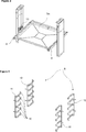
- Figure 1 – is a partial perspective view of an oven according to the invention.
- Figure 2 – is a perspective view of a movement mechanism of the oven of Fig. 1, with a movable tray supported by it.
- Figure 3 – is a perspective view of a support unit of the oven of Fig. 1.
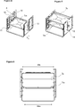
- Figure 4 – is a partial perspective view of the casing, the movement mechanism, the movable tray and the support unit of an oven according to the invention.
- Figure 5 – is the partial perspective view of Figure 4 with a static tray positioned on the support unit.
- Figure 6 – is a frontal view of the casing, the movement mechanism, the movable tray, the support unit and a static tray positioned on the support unit of an oven according to the invention.
- the oven 1 comprises a cooking chamber 2 wherein the trays containing the foodstuffs to be cooked are placed and a casing 3 surrounding the cooking chamber 2, configured as a box with front side open and having two opposite side walls 4, a rear wall 5 and a frontal aperture 6.
- the oven 1 further comprises a movement mechanism 7, associated to the side walls 4 of the casing 3 and comprising carrying means 8 whereon a movable tray T m can be placed to be moved upwards/downwards inside the cooking chamber 2, and a support unit 9 having carriers 10 for statically supporting at least one static tray T s in the cooking chamber 2. More in detail the support unit 9 comprises a plurality of carriers 10 aimed to support as much static trays T s placed one over the other and spaced apart.
- the movement mechanism 7 occupies a first vertical portion of each of the side walls 4 and the support unit 9 occupies a second different vertical portion of each of the side walls 4.
- the support unit 9 is mounted in the cooking chamber 2 and, according to an embodiment, it is fixed to the side walls 4.
- the movable carrying means 8 is spaced apart from each of the side walls 4 of a distance bigger than the extension of the support unit 9 from each of the side walls 4. This allows the carrying means 8 to be freely displaced vertically without interfering with the support unit 9.
- the support unit 9 for supporting static trays T s and the movement mechanism 7 for supporting and displacing a movable tray T m are both constantly available in the oven 1 according to the invention, so that a user can selectively use static trays T s or the movable tray T m without needing to perform any previous intervention.
- the movable tray T m has a width W m lower than the width W s of the static trays T s .
- the width is the dimension of the trays along a direction perpendicular to the side walls 4, as illustrated in Figure 6. This allows the movable tray T m not to interfere with the carriers 10 of the support unit 9 aimed to hold the static trays T s .
- the first vertical portion of each of the side walls 4 occupied by the movement mechanism 7 is substantially equidistant from the rear wall 5 and the frontal aperture 6. Therefore the movement mechanism 7 is associated substantially to a central portion of the side walls 4. This allows the movement mechanism 7 to securely hold the movable tray T m at intermediate positions of its side edges.
- the support unit 9 comprises a frontal rack 11 and a rear rack 12 mounted on each of the side walls 4 at the opposite sides of the first central vertical portion occupied by the movement mechanism 7, as illustrated in Figures 3 and 4 attached.
- Each of the racks in a preferred embodiment, is advantageously defined by a group of carriers 10 placed one over the other and spaced apart.
- the oven 1 further comprises an outer wall (not illustrated) surrounding the casing 3 and the movement mechanism 7 is mounted between the casing 3 and the outer wall and comprises sliding lifting elements 13 supporting the carrying means 8 inside the cooking chamber 2.
- each of the side walls 4 comprises a vertical slot 14 through which one of the lifting elements 13 extends.
- the movement mechanism 7 comprises two columns, each associated to a respective side wall 4 of the casing 3, in particular placed between the casing 3 and the outer wall, and substantially aligned between them.
- each column bears a motor M and transmission means for transmitting the motion of the motor M to one respective of the lifting elements 13, which is mounted on guides provided on the column, in order to displace it along a vertical path.
- the two counterposed lifting elements 13 carry the carrying means 8, so as to displace it vertically when they are moved by means of the respective motors M.
- the first vertical portion of the side walls 4 occupied by the movement mechanism 7 in this embodiment is substantially a portion extending at the vertical slot 14 and at the sides of the vertical slot 14 for a length L embracing the extension of the lifting elements 13 and allowing a sufficient clearance for its easy displacement, as clearly visible in Figures 5 and 6.
- the oven 1 allows the user to selectively use a movable tray T m or one or more static trays T s depending on the specific cooking needs.
- the user can hence place the foodstuff to be cooked in the desired tray or trays and select consequently the desired cooking program.
- the movement mechanism 7 will be actuated to raise and/or lower the carrying means 8 that supports the tray T m in the different stages of the cooking process, according to the cooking program, i.e. according to the data stored in the memory of a control unit of the oven 1 and associated to the selected cooking program.
- the user could even select to use the oven 1 with both a movable tray T m and one or more static trays T s positioned on the support unit 9, preferably positioned in this case on one of the carriers 10 closest to the top or bottom wall of the casing 3.
- control unit of the oven 1 controls the movement of the carrying means 8 in accordance with the cooking program selected by the user and in accordance with further inputs provided by the user concerning the presence of static trays T s in the cooking chamber 2 and their exact position in it.
- the oven 1 further comprises at least one sensor (not illustrated) for detecting the presence of a static tray T s on the support unit 9.
- the control unit connected to the sensors, upon receiving inputs from the sensor or the sensors related to the presence of a static tray T s and its exact position on the support unit 9, is programmed to adjust the movements of the carrying means 8 depending on these inputs.
- the oven 1 allows the user to comfortably use either the movable carrying means 8 or the support unit 9, or even both of them contemporary, in a safe manner and without any previous intervention being required.
Abstract
The present invention relates to an oven (1) comprising: - a cooking chamber (2) wherein the trays containing the foodstuffs to be cooked are placed, - a casing (3) surrounding the cooking chamber (2), configured as a box with front side open and having two opposite side walls (4), - a movement mechanism (7) associated to the side walls (4) of the casing (3) and comprising a carrying means (8) whereon a movable tray (Tm) can be placed to be moved upwards/downwards inside the cooking chamber (2), and - a support unit (9) having carriers (10) for statically supporting at least one static tray (Ts) in the cooking chamber (2).
Description
The present invention relates to an oven comprising a movement mechanism for vertically displacing a tray inside the cooking chamber. The oven according to the present invention further comprises a support unit for supporting one or more static trays.
In the state of the art, ovens comprising support units mounted on the side walls of the cooking chamber and having carriers which provide the trays to be placed one over the other and spaced apart are generally used.
In these embodiments, when the position of the tray inside the oven is required to be changed during a cooking process, the user has to perform this activity manually.
In the state of the art, ovens are also known comprising a movement mechanism for supporting a tray and displacing it upwards/downwards inside the cooking chamber. Ovens comprising such movement mechanism are for instance described in the German Patent Application No. DE102004042827 and in the European Patent No. EP0792087.
In these embodiments, the possibility to cook with more than one tray simultaneously disposed inside the oven is however not envisaged.
It is moreover known from the international patent application WO 2013000901 an oven comprising a movement mechanism and a detachable support unit having more than one static support whereon trays can be placed and which is placed inside the oven by the user when desired. Therefore, the movable tray or the support unit for a plurality of static trays may be used selectively.
The main drawback of the oven disclosed in WO 2013000901 resides on the fact that the support unit for the static trays needs to be removed from the oven and stored in a suitable place when the movable tray is in use, which is inconvenient.
The aim of the present invention is the realization of an oven wherein a movable tray or support unit for holding a plurality of static trays can be indifferently used without requiring previous interventions by the user.
In the oven realized in order to attain the aim of the present invention, explicated in the first claim and the respective claims thereof, both a carrying means that can be moved by means of a movement mechanism and also a support unit for supporting one or more static trays are contemporary provided in the cooking chamber, so that the user can selectively decide to use a movable tray or one or more static trays.
This is achieved by providing the oven according to the invention with a movement mechanism that occupies just a vertical portion of each of the side walls delimiting the cooking chamber, so that the support unit is mounted on the remaining portion of each of the side walls. In order to allow the free movement of the movable carrying means of the movement mechanism without having any interference between the carrying means and the fixed support unit, the movable carrying means is designed to be spaced apart from each of the side walls of a distance that is bigger than the extension of the support unit from each of the side walls. Therefore the movable carrying means, which extends parallel to the side walls for a length which approximately equal to the length of the cooking chamber, is free to slide in front of the support unit, spaced apart from it.
In an embodiment, the movable tray has a width lower than the width of the static trays.
According to an embodiment, the vertical portion of each of the side walls occupied by the movement mechanism is substantially centrally positioned on the side walls, equidistant from the rear wall and the frontal aperture of the casing.
In a further embodiment the support unit comprises a frontal rack and a rear rack mounted on each of the side walls at the opposite sides of the vertical portion occupied by the movement mechanism.
In an embodiment, the movement mechanism is mounted between the casing and an outer wall of the oven and comprises sliding lifting elements supporting the carrying means inside the cooking chamber and displacing them vertically in the cooking chamber.
In a further embodiment, each of the side wall comprises a vertical slot through which one of the lifting elements extends.
In an embodiment which allows the user to contemporary use both the movable tray and one or more static trays, the oven further comprises a control unit that controls the movement of the carrying means in accordance with the cooking program selected by the user and with inputs provided by the user concerning the presence of static trays in the cooking chamber.
In another embodiment, the oven comprises at least one sensor for detecting the presence of a static tray on the support unit and a control unit connected to the sensor, for receiving inputs from it related to the presence of a static tray and related to its position, and programmed to adjust the movements of the carrying means depending on these inputs.
By means of the present invention, the oven is provided to perform safe cooking by using the movable carrying means or the support unit or even both of them contemporary, as preferred by the user.
The oven realized in order to attain the aim of the present invention is illustrated in the attached figures, where:
Figure 1 – is a partial perspective view of an oven according to the invention.
Figure 2 – is a perspective view of a movement mechanism of the oven of Fig. 1, with a movable tray supported by it.
Figure 3 – is a perspective view of a support unit of the oven of Fig. 1.
Figure 4 – is a partial perspective view of the casing, the movement mechanism, the movable tray and the support unit of an oven according to the invention.
Figure 5 – is the partial perspective view of Figure 4 with a static tray positioned on the support unit.
Figure 6 – is a frontal view of the casing, the movement mechanism, the movable tray, the support unit and a static tray positioned on the support unit of an oven according to the invention.
The elements illustrated in the figures are numbered as follows:
- Oven
- Cooking chamber
- Casing
- Side wall
- Rear wall
- Frontal aperture
- Movement mechanism
- Carrying means
- Support unit
- Carriers
- Frontal rack
- Rear rack
- Sliding lifting elements
- Vertical slot
The oven 1 comprises a cooking chamber 2 wherein the trays containing the foodstuffs to be cooked are placed and a casing 3 surrounding the cooking chamber 2, configured as a box with front side open and having two opposite side walls 4, a rear wall 5 and a frontal aperture 6.
The oven 1 further comprises a movement mechanism 7, associated to the side walls 4 of the casing 3 and comprising carrying means 8 whereon a movable tray Tm can be placed to be moved upwards/downwards inside the cooking chamber 2, and a support unit 9 having carriers 10 for statically supporting at least one static tray Ts in the cooking chamber 2. More in detail the support unit 9 comprises a plurality of carriers 10 aimed to support as much static trays Ts placed one over the other and spaced apart.
According to the present invention the movement mechanism 7 occupies a first vertical portion of each of the side walls 4 and the support unit 9 occupies a second different vertical portion of each of the side walls 4. More in detail, the support unit 9 is mounted in the cooking chamber 2 and, according to an embodiment, it is fixed to the side walls 4. The movable carrying means 8 is spaced apart from each of the side walls 4 of a distance bigger than the extension of the support unit 9 from each of the side walls 4. This allows the carrying means 8 to be freely displaced vertically without interfering with the support unit 9.
Therefore, the support unit 9 for supporting static trays Ts and the movement mechanism 7 for supporting and displacing a movable tray Tm are both constantly available in the oven 1 according to the invention, so that a user can selectively use static trays Ts or the movable tray Tm without needing to perform any previous intervention.
According to an embodiment, the movable tray Tm has a width Wm lower than the width Ws of the static trays Ts. Considering the trays positioned in the cooking chamber 2 of the oven 1, the width is the dimension of the trays along a direction perpendicular to the side walls 4, as illustrated in Figure 6. This allows the movable tray Tm not to interfere with the carriers 10 of the support unit 9 aimed to hold the static trays Ts.
In an embodiment illustrated in the attached figures, the first vertical portion of each of the side walls 4 occupied by the movement mechanism 7 is substantially equidistant from the rear wall 5 and the frontal aperture 6. Therefore the movement mechanism 7 is associated substantially to a central portion of the side walls 4. This allows the movement mechanism 7 to securely hold the movable tray Tm at intermediate positions of its side edges.
In a further embodiment, the support unit 9 comprises a frontal rack 11 and a rear rack 12 mounted on each of the side walls 4 at the opposite sides of the first central vertical portion occupied by the movement mechanism 7, as illustrated in Figures 3 and 4 attached. Each of the racks, in a preferred embodiment, is advantageously defined by a group of carriers 10 placed one over the other and spaced apart.
According to an embodiment, the oven 1 further comprises an outer wall (not illustrated) surrounding the casing 3 and the movement mechanism 7 is mounted between the casing 3 and the outer wall and comprises sliding lifting elements 13 supporting the carrying means 8 inside the cooking chamber 2.
According to a further embodiment, each of the side walls 4 comprises a vertical slot 14 through which one of the lifting elements 13 extends.
More in detail, according to an embodiment, the movement mechanism 7 comprises two columns, each associated to a respective side wall 4 of the casing 3, in particular placed between the casing 3 and the outer wall, and substantially aligned between them. According to this embodiment, each column bears a motor M and transmission means for transmitting the motion of the motor M to one respective of the lifting elements 13, which is mounted on guides provided on the column, in order to displace it along a vertical path. The two counterposed lifting elements 13 carry the carrying means 8, so as to displace it vertically when they are moved by means of the respective motors M.
The first vertical portion of the side walls 4 occupied by the movement mechanism 7 in this embodiment is substantially a portion extending at the vertical slot 14 and at the sides of the vertical slot 14 for a length L embracing the extension of the lifting elements 13 and allowing a sufficient clearance for its easy displacement, as clearly visible in Figures 5 and 6.
Therefore the oven 1 according to the present invention allows the user to selectively use a movable tray Tm or one or more static trays Ts depending on the specific cooking needs. The user can hence place the foodstuff to be cooked in the desired tray or trays and select consequently the desired cooking program.
In case the user selects to use the movable tray Tm, the movement mechanism 7 will be actuated to raise and/or lower the carrying means 8 that supports the tray Tm in the different stages of the cooking process, according to the cooking program, i.e. according to the data stored in the memory of a control unit of the oven 1 and associated to the selected cooking program.
According to further embodiments of the oven 1, the user could even select to use the oven 1 with both a movable tray Tm and one or more static trays Ts positioned on the support unit 9, preferably positioned in this case on one of the carriers 10 closest to the top or bottom wall of the casing 3.
In particular, to this aim, in one embedment the control unit of the oven 1 controls the movement of the carrying means 8 in accordance with the cooking program selected by the user and in accordance with further inputs provided by the user concerning the presence of static trays Ts in the cooking chamber 2 and their exact position in it.
This allows the user for instance to place a static tray Ts at the bottom of the cooking chamber 2, while using contemporary the movable tray Tm which, accordingly, will be displaced by the movement mechanism 7, controlled by the control unit, along a vertical path extending only on the upper part of the cooking chamber 2.
According to a further embodiment, which is alternative or additional to the embodiment above described, the oven 1 further comprises at least one sensor (not illustrated) for detecting the presence of a static tray Ts on the support unit 9. The control unit, connected to the sensors, upon receiving inputs from the sensor or the sensors related to the presence of a static tray Ts and its exact position on the support unit 9, is programmed to adjust the movements of the carrying means 8 depending on these inputs.
By means of the present invention, the oven 1 allows the user to comfortably use either the movable carrying means 8 or the support unit 9, or even both of them contemporary, in a safe manner and without any previous intervention being required.
Claims (8)
- An oven (1) comprising:- a cooking chamber (2) wherein the trays containing the foodstuffs to be cooked are placed,- a casing (3) surrounding the cooking chamber (2), configured as a box with front side open and having two opposite side walls (4),- a movement mechanism (7) associated to the side walls (4) of the casing (3) and comprising carrying means (8) whereon a movable tray (Tm) can be placed to be moved upwards/downwards inside the cooking chamber (2),- a support unit (9) having carriers (10) for statically supporting at least one static tray (Ts) in the cooking chamber (2),characterized in that the movement mechanism (7) occupies a first vertical portion of each of the side walls (4) and the support unit (9) occupies a second different vertical portion of each of the side walls (4), the movable carrying means (8) being spaced apart from each of the side walls (4) of a distance bigger than the extension of the support unit (9) from each of the side walls (4).
- An oven (1) as in Claim 1, characterized in that the movable tray (Tm) has a width (Wm) lower than the width (Ws) of the static trays (Ts).
- An oven (1) as in Claim 1 or 2, characterized in that the casing (3) has a rear wall (5) and a frontal aperture (6) and the first vertical portion of each of the side walls (4) occupied by the movement mechanism (7) is substantially equidistant from the rear wall (5) and the frontal aperture (6).
- An oven (1) as in Claim 3, characterized in that the support unit (9) comprises a frontal rack (11) and a rear rack (12) mounted on each of the side walls (4) at the opposite sides of the first vertical portion occupied by the movement mechanism (7).
- An oven (1) as in any of the previous claims, characterized in that it further comprises an outer wall surrounding the casing (3) and the movement mechanism (7) is mounted between the casing (3) and the outer wall and comprises sliding lifting elements (13) supporting the carrying means (8) inside the cooking chamber (2).
- An oven (1) as in Claim 5, characterized in that each of the side wall (4) comprises a vertical slot (14) through which one of the lifting elements (13) extends.
- An oven (1) as in any of the previous claims, characterized in that it further comprises a control unit that controls the movement of the carrying means (8) in accordance with the cooking program selected by the user and with inputs provided by the user concerning the presence of static trays (Ts) in the cooking chamber (2).
- An oven (1) as in any of the previous claims, characterized in that it further comprises at least one sensor for detecting the presence of a static tray (Ts) on the support unit (9) and a control unit connected to the sensor, for receiving inputs from it related to the presence of a static tray (Ts), and programmed to adjust the movements of the carrying means (8) depending on said inputs.
Priority Applications (2)
| Application Number | Priority Date | Filing Date | Title |
|---|---|---|---|
| PCT/EP2015/065499 WO2017005309A1 (en) | 2015-07-07 | 2015-07-07 | An oven |
| EP15734398.9A EP3320271B1 (en) | 2015-07-07 | 2015-07-07 | An oven |
Applications Claiming Priority (1)
| Application Number | Priority Date | Filing Date | Title |
|---|---|---|---|
| PCT/EP2015/065499 WO2017005309A1 (en) | 2015-07-07 | 2015-07-07 | An oven |
Publications (1)
| Publication Number | Publication Date |
|---|---|
| WO2017005309A1 true WO2017005309A1 (en) | 2017-01-12 |
Family
ID=53514192
Family Applications (1)
| Application Number | Title | Priority Date | Filing Date |
|---|---|---|---|
| PCT/EP2015/065499 WO2017005309A1 (en) | 2015-07-07 | 2015-07-07 | An oven |
Country Status (2)
| Country | Link |
|---|---|
| EP (1) | EP3320271B1 (en) |
| WO (1) | WO2017005309A1 (en) |
Families Citing this family (2)
| Publication number | Priority date | Publication date | Assignee | Title |
|---|---|---|---|---|
| DE102019103418A1 (en) * | 2019-02-12 | 2020-08-13 | Miele & Cie. Kg | Cooking appliance |
| WO2022136323A1 (en) * | 2020-12-24 | 2022-06-30 | Koninklijke Philips N.V. | Steam cooking apparatus |
Citations (6)
| Publication number | Priority date | Publication date | Assignee | Title |
|---|---|---|---|---|
| US2834334A (en) * | 1956-07-30 | 1958-05-13 | Gen Electric | Oven rack with raisable shelf portion |
| JPS63150220U (en) * | 1987-03-24 | 1988-10-03 | ||
| EP0792087A2 (en) | 1996-02-23 | 1997-08-27 | Samsung Electronics Co., Ltd. | Method of controlling the driving of a tray of a microwave oven |
| DE102004042827A1 (en) | 2004-08-27 | 2006-03-02 | E.G.O. Elektro-Gerätebau GmbH | Baking oven for baking e.g. pizza, has baking muffle cover whose position is changeable vertically in relation to baking muffle base, and flexible sealing is provided between side panels of baking muffle and base or cover |
| WO2013000901A1 (en) | 2011-06-27 | 2013-01-03 | Arcelik Anonim Sirketi | An oven |
| WO2013116606A2 (en) * | 2012-02-03 | 2013-08-08 | Euro-Pro Operating Llc | Oven with steam infusion |
-
2015
- 2015-07-07 WO PCT/EP2015/065499 patent/WO2017005309A1/en active Application Filing
- 2015-07-07 EP EP15734398.9A patent/EP3320271B1/en not_active Not-in-force
Patent Citations (6)
| Publication number | Priority date | Publication date | Assignee | Title |
|---|---|---|---|---|
| US2834334A (en) * | 1956-07-30 | 1958-05-13 | Gen Electric | Oven rack with raisable shelf portion |
| JPS63150220U (en) * | 1987-03-24 | 1988-10-03 | ||
| EP0792087A2 (en) | 1996-02-23 | 1997-08-27 | Samsung Electronics Co., Ltd. | Method of controlling the driving of a tray of a microwave oven |
| DE102004042827A1 (en) | 2004-08-27 | 2006-03-02 | E.G.O. Elektro-Gerätebau GmbH | Baking oven for baking e.g. pizza, has baking muffle cover whose position is changeable vertically in relation to baking muffle base, and flexible sealing is provided between side panels of baking muffle and base or cover |
| WO2013000901A1 (en) | 2011-06-27 | 2013-01-03 | Arcelik Anonim Sirketi | An oven |
| WO2013116606A2 (en) * | 2012-02-03 | 2013-08-08 | Euro-Pro Operating Llc | Oven with steam infusion |
Also Published As
| Publication number | Publication date |
|---|---|
| EP3320271A1 (en) | 2018-05-16 |
| EP3320271B1 (en) | 2019-02-20 |
Similar Documents
| Publication | Publication Date | Title |
|---|---|---|
| US20070284982A1 (en) | Telescopic pull-out device for attachment to a support frame arranged in the processing chamber of a household appliance | |
| US9109804B2 (en) | Appliance with vertically adjustable rack | |
| CN107847078B (en) | Convection oven with removable air plenum | |
| US8733862B1 (en) | Adjustable shelf support assembly for an appliance | |
| US8936333B2 (en) | Appliance and a rack assembly for the same | |
| US20130291854A1 (en) | Convection oven using rack support ducts for air flow | |
| EP3320271B1 (en) | An oven | |
| WO2007067639A3 (en) | Open holding cabinet, trays and controls | |
| US20130284161A1 (en) | Oven appliance with features for selecting convection air flow direction | |
| EP2326237B1 (en) | A dishwasher with drawer attached to tub roof | |
| KR20060069117A (en) | A cooking cavity dividing plate and electric oven range having the same | |
| US20130118471A1 (en) | Extendable rack mounting system for an oven appliance | |
| WO2014082828A1 (en) | Oven comprising telescopic rails | |
| KR101683085B1 (en) | Cauldron type induction cooker using electromagnetic induction device | |
| WO2017102247A1 (en) | An oven having an adjustable height rack assembly | |
| US20160195281A1 (en) | Oven rack storage | |
| US20150101590A1 (en) | Spring loaded shelf for an oven appliance | |
| EP3336436A1 (en) | Cooking hob with a monitoring device | |
| WO2013000901A1 (en) | An oven | |
| WO2013026789A1 (en) | An oven comprising a movable support | |
| EP2469190B1 (en) | A cooking hob including an upper part and a base part | |
| KR20160072797A (en) | Device for guiding a push-in element, and kitchen installation having such a device | |
| WO2017005310A1 (en) | A cooking device | |
| EP2187134B1 (en) | Oven, especially domestic oven | |
| KR100948655B1 (en) | Cooking appliance |
Legal Events
| Date | Code | Title | Description |
|---|---|---|---|
| 121 | Ep: the epo has been informed by wipo that ep was designated in this application |
Ref document number: 15734398 Country of ref document: EP Kind code of ref document: A1 |
|
| NENP | Non-entry into the national phase |
Ref country code: DE |
|
| WWE | Wipo information: entry into national phase |
Ref document number: 2015734398 Country of ref document: EP |