WO2017004882A1 - 面向平面显示设备的视频立体化绘制方法 - Google Patents
面向平面显示设备的视频立体化绘制方法 Download PDFInfo
- Publication number
- WO2017004882A1 WO2017004882A1 PCT/CN2015/089104 CN2015089104W WO2017004882A1 WO 2017004882 A1 WO2017004882 A1 WO 2017004882A1 CN 2015089104 W CN2015089104 W CN 2015089104W WO 2017004882 A1 WO2017004882 A1 WO 2017004882A1
- Authority
- WO
- WIPO (PCT)
- Prior art keywords
- depth
- frame
- foreground
- point
- points
- Prior art date
Links
Images


Classifications
-
- G—PHYSICS
- G06—COMPUTING; CALCULATING OR COUNTING
- G06T—IMAGE DATA PROCESSING OR GENERATION, IN GENERAL
- G06T7/00—Image analysis
-
- G—PHYSICS
- G06—COMPUTING; CALCULATING OR COUNTING
- G06T—IMAGE DATA PROCESSING OR GENERATION, IN GENERAL
- G06T2207/00—Indexing scheme for image analysis or image enhancement
- G06T2207/10—Image acquisition modality
- G06T2207/10016—Video; Image sequence
- G06T2207/10021—Stereoscopic video; Stereoscopic image sequence
-
- G—PHYSICS
- G06—COMPUTING; CALCULATING OR COUNTING
- G06T—IMAGE DATA PROCESSING OR GENERATION, IN GENERAL
- G06T2207/00—Indexing scheme for image analysis or image enhancement
- G06T2207/10—Image acquisition modality
- G06T2207/10024—Color image
-
- G—PHYSICS
- G06—COMPUTING; CALCULATING OR COUNTING
- G06T—IMAGE DATA PROCESSING OR GENERATION, IN GENERAL
- G06T2207/00—Indexing scheme for image analysis or image enhancement
- G06T2207/20—Special algorithmic details
- G06T2207/20228—Disparity calculation for image-based rendering
Definitions
- the present invention relates to the field of digital image processing, and in particular to a video stereoscopic rendering method for a flat display device that does not depend on a special photographing device, a display device, and a viewing device.
- Stereo video technology is the development direction of multimedia technology in the future, and has broad application prospects in the fields of planning and design evaluation, film and television entertainment.
- the existing stereoscopic technology is mainly divided into 3D glasses type and non-glass type.
- the former includes photometry, time division, color separation technology, etc.; the latter includes light barrier technology, lenticular lens technology, holographic projection, and the like.
- the above technologies all have good stereoscopic effects, and have also been applied in the film and television industry.
- these technologies still have the following disadvantages: 1.
- Most rely on auxiliary equipment such as 3D glasses and special display screens, which greatly limits their promotion and use. 2, filter glasses, fence display, cylindrical lens display and other auxiliary equipment to reduce the brightness and resolution of the original video; 3, with higher manufacturing and maintenance costs.
- the technical problem to be solved by the present invention is to provide a video stereoscopic rendering method for a flat display device, so as to improve the traditional stereoscopic video, which must be dependent on the device for viewing, which is not conducive to popularization.
- a video stereoscopic rendering method for a flat display device comprising the following steps:
- Step 1 Extracting the color frame and the depth frame: obtaining a sequence of the color frame I c and the depth frame I d input in real time using a Kinect depth camera;
- Step 2 Depth frame stretching: performing linear transformation on the depth frame and bilateral filtering to obtain an image I d ';
- Step 3 Dividing a fine foreground mask: applying a frame difference method to the adjacent color frame I c to subtract the background to obtain a rough foreground F r , and then applying image morphology corrosion to the rough foreground F r to remove small bright regions Delete the smaller branch and only retain the branch with the largest area, and segment the rough motion foreground mask. For each frame, find the point p with the smallest depth in the rough foreground F r of the frame, and perform the breadth-first search to find its Continuous points in a three-dimensional scene, resulting in a fine foreground mask F p ;
- Step 4 Calculate the position of the reference line: determine the reference lines l left and l right in the left and right half of the scene;
- Step 5 Applying the camera geometry principle to re-render the color frame I c and the image I d ' to the new color frame R c and the new depth frame R d on the imaging plane layer by layer: for the color frame I c and the image I d ' Points are divided into layers by depth from large to small, and the camera geometrical photography is performed on the points in the color frame I c and the image I d ', and the cracks are repaired, and finally the repaired layer is drawn to a new color. a frame R c and a new depth frame R d ;
- Step 6 Construct a scene triangle mesh to repair pixel missing in the new color frame R c and the new depth frame R d : connect the adjacent three scene points in the color frame I c and the new depth frame I d ' into one
- the triangle mesh makes the whole scene fit into a polyhedron.
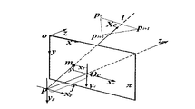
- the m point is the missing point of the pixel on the imaging plane ⁇ of the camera, and the line l connecting the p and m points of the projection center, if l intersects with a triangle mesh at the point X c , then the point m is the point where the point X c is projected on the imaging plane ⁇ of the camera, and the color value at X c is repaired;
- Step 7 Appropriate blurring of the foreground: record the average depth of the two white lines as d w , and blur the points in the new color frame R c whose depth is greater than d w , and the greater the depth, the larger the blur window;
- Step 8 Insert a reference line into R cb to obtain a result image R cbp : record the position of the two reference lines calculated in step 4 as Loc, apply a camera geometric perspective transformation to Loc, and obtain a new reference line position Loc 'and Inserting the resulting image R cbp obtained in R cb completes the entire drawing process.
- the depth map is used to repair the depth map, and the obtained image is repaired. After color frames and depth frames.
- the maximum depth and the minimum depth in all the depth frames I d are counted, and the depth variation range (d 1 , d 2 ) of the video is obtained, and the depth range is mapped to the depth range by using a linear transformation ( An image I d ' of d min , d max ), where d 1 >d min , d 2 ⁇ d max , and the calculation formula is:
- the image I d ' is bilaterally filtered to obtain a depth frame that preserves the edge and smoothes.
- a virtual plane is determined to heighten the depth of the foreground, the foreground mask labeled F p fine three-dimensional scene in the fine foreground, the position of the reference line algorithm is calculated as follows:
- the fine foreground foreground mask F p into a top projection of the foreground F v, and calculates the minimum circumscribed rectangular plan of the foreground F v B.
- Mark all the foreground views onto the moving foreground top view track V find the outer moment B 1 with the smallest center of gravity in all frames, the outer moment B 2 with the largest center of gravity, the outer moment B 1 with the smallest center of gravity, and the largest depth of gravity
- the connection of the external moment B 2 is obtained, and the slope k is obtained.
- the non-zero point set in the moving view top view trajectory V is recorded as the set P, and the point element is denoted as p;
- p is the pixel point in the set P, representing the trajectory of the foreground
- d s is the start of the search reference line depth
- d e is the end of the search reference line depth
- l 1 and l 2 are the bisectors of the picture, and the point closest to l 1 when l left is selected , when l is right , the point close to l 2 is preferred.
- the specific choice is as follows:
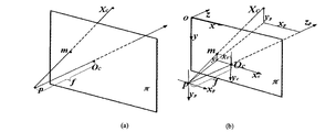
- step 5 the mapping expression for re-rendering the scene point X c to the imaging plane point m is the following formula (5):
- x, y, z are the coordinates of the scene point X c (x, y, z) in the corresponding o-xyz coordinate system
- x', y' is the imaging plane point m(x, y) at o-xy
- f is the distance from the projection center p to the center O c of the imaging plane
- width, height is the width and height of the imaging plane.
- step 5 the cracks are repaired layer by layer by using the inpainting algorithm for the points in I c and I d '.
- step 6 the color value at X c is calculated from its vertex pi, p i+1 , p i+2 according to the following formula (6):
- step 7 for all the pixel points p in the new color frame R c , R d has its corresponding depth d p , and the fuzzy window size WinSize at the p point is calculated according to d p :
- depth max is the maximum depth in the scene
- d w is the average depth of the two reference lines
- d p is the depth of point p
- win max is the corresponding fuzzy window at depth max
- win min is the corresponding fuzzy window at d w .
- step 8 a camera geometric perspective transformation as shown in the formula (7) is applied to the Loc to obtain a new reference line position Loc'.
- the present invention has the following technical effects:
- the present invention does not rely on any special display or viewing device, and only performs digital image processing on the video, thereby having no influence on the brightness and resolution of the original video, and is advantageous for promotion and promotion compared with the traditional dependent video stereoscopic technology. Save on manufacturing and post-maintenance costs.
- the present invention uses two reference lines to define a virtual plane, which corresponds to the screen of the display, and the process of moving the foreground from the rear of the virtual plane to the front brings a motion foreground to the visual perception of the display. , thus showing a dynamic stereo effect.
- the invention uses the camera geometry principle to project the points in the three-dimensional scene to the imaging plane, and the re-rendered color map visually reflects the perspective relationship of the depth and the near.
- this video stereo technology can be used for film and television entertainment, advertising media and so on.
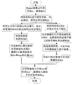
- FIG. 1 is a flow chart of a method for drawing a stereoscopic video of a flat display device according to the present invention.
- Figure 3 is a depth map I d ' after stretching.
- Figure 4 is a schematic diagram of the foreground projection obtained from the foreground mask.
- Figure 5 is a view of the foreground motion direction from the foreground motion trajectory top view V.
- FIG. 6 is a schematic diagram of screening l left and l right from candidate points.
- Figure 7 is a schematic diagram of a basic pinhole model.
- Figure 8 is a scene repainted with camera geometry projection.
- FIG. 10 is a view of repairing a color frame R c and a depth frame R d after a pixel is missing.
- Figure 11 is a blurred color frame R cb .
- Fig. 12 is a color frame R cbp after the reference line is inserted.
- Figure 13 is a sequence of original video color frames I c .
- Figure 14 is a redrawn color frame R cbp sequence.
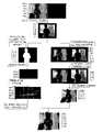
- 15 is a display effect of an embodiment of a video stereoscopic rendering method for a flat display device.
- I c is an input color frame
- I d is an input depth frame
- I d ' is a depth frame I d
- F r is a rough foreground obtained by using the frame difference method for I c
- F p is a fine foreground mask segmented by the depth map and the BFS algorithm on the basis of F r
- F v is a foreground top view of the F p projection in a plan view angle
- V is a superposition of F v non-zero pixel points of all frames.
- the foreground is a top view of the trajectory
- l left and l right are two reference lines for determining the virtual plane
- Loc is the position of the two reference lines
- R c and R d are respectively I c and I d ' Color frame and new depth frame
- R cb is the result image of foreground blurring of the distant view in R c
- Loc ' is the position after perspective transformation of two reference lines
- R cbp is inserted into Loc' of R cb The resulting image after the reference line.
- the invention provides a video stereoscopic rendering method for a planar display device, which enhances the stereoscopic effect by re-rendering the video color frame and the depth frame.
- the method re-renders the stereoscopic video to the flat display device by comprehensively applying the virtual depth of field to the plane, expanding the depth of field based on the camera geometry principle and creating a depth of field based on the Gaussian filter, so that it can also be used on the conventional flat display device. Shows a three-dimensional effect.
- the basic principle of the stereoscopic video rendering method of the present invention is:
- two reference lines are used to determine the virtual plane to highlight the depth of field:
- the OpenNI-driven Kinect camera is used to acquire the real-time color frame I c and the corresponding depth frame I d sequence, for the depth frame I d pixels Missing, depth frame contour and real scene contour mismatch, etc., using the depth frame refinement algorithm to repair; then, applying a linear transformation to the depth frame, so that the scene depth is mapped from a smaller (d 1 , d 2 ) range to The large (d min , d max ) range, due to the linear transformation, the original continuous scene points appear a large depth difference, so the transformed depth frame is bilaterally filtered, and the depth frame is smoothed on the premise of retaining the edge.
- a new depth frame I d ' A new depth frame I d '; Then, a frame difference method is applied to the adjacent color frame I c to obtain a rough motion foreground map F r , and based on this, the depth information and the breadth-first search BFS are combined to segment the fine motion.
- the foreground F p marks the moving foreground F p in the three-dimensional scene and projects it into the top view V, and calculates two reference lines according to the moving trajectory characteristics of the moving foreground top view V. Left and l right position Loc.
- the depth of field is extended and created by the color frame embedded in the virtual plane:
- the camera pinhole model is used to perform perspective transformation on the point in the scene; then, the scene after the transformation position is redrawn in the new color frame R. c and the depth frame R d , the color map R c after the simulation simulates the near and large image of the camera image, so as to better express the extended depth of field; then, construct the scene triangle mesh to the color frame R c And the pixel missing in the depth frame R d is repaired, the appropriate blur is added to the foreground in R c to create the parallax, the effect of the near real and the far is created, and the color frame R cb is obtained ; finally, the first stage is calculated.
- the reference line position Loc is also subjected to perspective transformation to obtain a new position Loc', and a reference frame is inserted in R cb to obtain a color frame R cbp in which the virtual plane is embedded.
- the virtual plane is equivalent to the screen of the display, and the foreground "rushes" out of the screen of the display to produce a dynamic stereo effect.
- a video with a dynamic stereo effect that can be projected on a general flat display device is obtained.
- Step 1 Extract color frames and depth frames. Kinect depth camera using the acquired real-time input frame color depth frame I c and I d sequence.
- the depth frame I d there is a phenomenon that the "black hole" caused by the missing pixel and the contour of the depth frame do not match the contour of the color frame, and need to be repaired.
- Document 1 (-Jiao J, Wang R, Wang W, et al.Local Stereo Matching with Improved Matching Cost and Disparity Refinement [J].
- the depth map refinement algorithm repairs the depth map, and the obtained color frame and depth frame are as shown in FIG. 2 .
- Step 2 Deep frame stretching.
- the maximum depth and the minimum depth in all depth frames I d are counted, and the depth variation range (d 1 , d 2 ) of the video is obtained, and is mapped to the I d ' of the depth range (d min , d max ) by linear transformation.
- I d ' is an image obtained by linear transformation and bilateral filtering of the depth frame I d , and the calculation formula is:
- the bilateral filtering is performed on I d ', and the depth frame with the preserved edge and smoothed is shown in FIG. 3 .
- Step 3 Split the fine foreground mask. Applying the frame difference method to the adjacent color frames I c subtracts the background to obtain F r , and then applies image morphology "corrosion" to F r to eliminate small bright areas. Deleting a smaller branch only preserves the branch with the largest area, and splits out a rough motion foreground mask. For each frame, find the point p with the smallest depth in the rough foreground F r of the frame, and perform a breadth-first search to find a continuous point in the three-dimensional scene to obtain a fine foreground mask F p , as shown in Fig. 4(a). Shown.
- Step 4 Calculate the reference line position.
- the reference lines l left and l right will be determined in the left and right halves of the scene, respectively, and a virtual plane is determined to highlight the foreground depth of field.
- F p marks the foreground in a more elaborate 3D scene.
- the algorithm for calculating the reference line position is as follows:
- the foreground F p (FIG. 4 (a) below) into a top projection foreground F v (FIG. 4 (b) below), and calculates the minimum bounding rectangle F v B.
- Mark all the foreground views to a map - the foreground of the motion is overlooked on the trajectory V.
- the foreground view of the motion foreground is shown in Fig. 5.
- the non-zero point set in the graph is P, and the point element is denoted as p.
- p is the pixel point in the set P, representing the trajectory of the foreground
- d s is the start of the search reference line depth
- d e is the end of the search reference line depth
- the area of the white patch mark in the top view V of the motion foreground track satisfies the formula (2), which is the candidate point of the reference line l left and l right , and l 1 and l 2 are the bisectors of the picture.
- the point closest to l 1 is preferentially selected
- the point close to l 2 is preferentially selected to make the picture composition beautiful.
- Figure 6 demonstrates a screening result for k ⁇ 0, and the resulting reference line position is shown as l left , l right as shown in the figure.
- Step 5 Apply the camera geometry principle to re-render I c and I d ' to the color frame R c and depth frame R d on the imaging plane.
- the depth is divided into five layers of layer[0] ⁇ layer[4] according to the depth, and the camera geometric projections are performed on the points in I c and I d 'by layer by layer.
- the inpainting algorithm repairs the cracks and finally draws the repaired layer onto R c and R d .
- Figure 7 illustrates the principle of redrawing the scene point X c to the imaging plane point m, the expression of which is calculated according to equation (7):
- x, y, z are the coordinates of the scene point X c (x, y, z) in the Figure 7o-xyz coordinate system
- x', y' are m(x, y) in the o-xy coordinate system.
- coordinate. f is the distance from the projection center p to the center O c of the imaging plane
- width and height are the width and height of the imaging plane.
- Step 6 Construct a scene triangle mesh to fix missing pixels in R c and R d .
- Fig. 8(a)(b) the "black hole” phenomenon caused by the absence of pixels existing in R c and R d .
- the three adjacent scene points in I c and I d ' are connected into a triangle mesh, and the entire scene is fitted into a polyhedron.
- the principle of using the scene mesh to repair pixel missing is shown in Figure 9.
- the m point in Fig. 9 is the missing point of the pixel on the imaging plane ⁇ of the camera, and the straight line l connecting the p and m points of the projection center.
- Step 7 Appropriate blurring of the vision.
- the average depth of the two white lines is d w , and the point of depth greater than d w in R c is blurred, and the greater the depth, the larger the blur window is given.
- R c is p
- R d has the corresponding depth d p
- fuzzy window size is calculated at p WinSize d p according to:
- depth max is the maximum depth in the scene
- d w is the average depth of the two reference lines
- d p is the depth of point p
- win max is the corresponding blur window at depth max , here is set to 15
- win min is d w
- Corresponding blur window set to 1 here.
- the R cb obtained after the blur is as shown in FIG.
- Step eight inserting a reference line in R cb to obtain a result image R cbp .
- the position of the two reference lines has been calculated and recorded as Loc.
- the camera geometric perspective transformation shown in the formula (7) is also applied to the Loc to obtain a new reference line position Loc', and the result image R cbp after the reference line is inserted is as shown in FIG.
- the video stereoscopic rendering method for the flat display device completes all the steps, the original video frame is as shown in FIG. 13, and the redrawn frame is as shown in FIG. 14, and the embodiment shows the effect as shown in FIG. .
Abstract
一种面向平面显示设备的视频立体化绘制方法,步骤包括:提取彩色帧和深度帧:获取实时输入的彩色帧I c和深度帧I d序列;深度帧拉伸:对深度帧进行线性变换、双边滤波后得到图像I d';分割精细的前景掩码;计算参照线位置:在场景的左半边和右半边分别确定参照线1 left和1 right;应用摄像机几何原理逐层将彩色帧I c和图像I d'重新绘制到成像平面上的新彩色帧R c和新深度帧R d;构造场景三角网格修复新彩色帧R c和新深度帧R d中出现的像素缺失;对远景进行适当的模糊;在R cb中插入参考线得到结果图像R cbp。不需任何辅助硬件设备,通过对视频帧进行相应图像处理,即可在平面显示设备上较好地突出运动前景、增强视频的动态立体呈现效果。
Description
本发明涉及数字图像处理领域,尤其是指一种不依赖于特殊拍摄设备、显示设备、观看设备的面向平面显示设备的视频立体化绘制方法。
立体视频技术是未来多媒体技术的发展方向,在规划设计方案评估、影视娱乐等领域有广泛的应用前景。
现有的立体技术主要分为3D眼镜式和非眼镜式。前者包括光分法、时分法、分色技术等;后者包括光屏障式技术、柱状透镜技术、全息投影等。以上技术都有较好的立体效果,在影视行业也得到了应用,但是,以上这些技术仍然存在以下缺点:1、大都依赖于3D眼镜、特殊显示屏幕等辅助设备,大大地限制了其推广使用;2、滤光眼镜、栅栏式显示屏、柱状透镜显示屏等辅助设备降低了原视频的亮度和分辨率;3、具有较高的制造和维护成本。
因而,研究一种不依赖于特制设备的视频立体化技术,在立体视频亟需普及的今天具有重要意义。
本发明所要解决的技术问题是,提供一种面向平面显示设备的视频立体化绘制方法,以改善传统的立体视频必须依赖设备才能观看,不利于推广的问题。
问题的解决方案
为解决上述技术问题,本发明采用如下技术方案:一种面向平面显示设备的视频立体化绘制方法,包括如下步骤:
步骤一、提取彩色帧和深度帧:使用Kinect深度相机获取实时输入的彩色帧Ic和深度帧Id序列;
步骤二、深度帧拉伸:对深度帧进行线性变换、双边滤波后得到图像Id’;
步骤三、分割精细的前景掩码:对相邻的彩色帧Ic应用帧差法对背景进行减除
得到粗略前景Fr,再对粗略前景Fr运用图像形态学腐蚀,剔除细小的明亮区域,删除较小的分支只保留面积最大的分支,分割出粗略的运动前景掩码,对于每一帧,寻找该帧粗略前景Fr中深度最小的点p,并进行广度优先搜索,寻找其在三维场景中连续的点,得到精细的前景掩码Fp;
步骤四、计算参照线位置:在场景的左半边和右半边分别确定参照线lleft和lright;
步骤五、应用摄像机几何原理逐层将彩色帧Ic和图像Id’重新绘制到成像平面上的新彩色帧Rc和新深度帧Rd:对于彩色帧Ic和图像Id’中的点,按深度由大到小均分为多层,逐层对彩色帧Ic和图像Id’中的点进行摄像机几何摄影并修复其中的裂纹,最后将修复后的图层绘制到新彩色帧Rc和新深度帧Rd上;
步骤六、构造场景三角网格修复新彩色帧Rc和新深度帧Rd中出现的像素缺失:将彩色帧Ic和新深度帧Id’中相邻的三个场景点连成一个个三角形网格,使整个场景被拟合成一个多面体,m点是摄像机成像平面π上的像素缺失点,连接过投影中心p和m点的直线l,如果l与某个三角形网格相交于点Xc,则m点是点Xc投影在摄像机成像平面π的点,对Xc处的颜色值进行修复;
步骤七、对远景进行适当的模糊:记两条白线的平均深度为dw,对新彩色帧Rc中深度大于dw的点进行模糊,深度越大赋予越大的模糊窗口;
步骤八、在Rcb中插入参考线得到结果图像Rcbp:将步骤四中计算出的两条参照线的位置记为Loc,对Loc施加摄像机几何透视变换,得到新的参照线位置Loc’并插入Rcb中获得的结果图像Rcbp,即完成整个绘制过程。
进一步地,在所述步骤一中,针对深度帧Id中存在像素缺失导致的黑洞和深度帧轮廓与彩色帧轮廓不匹配的现象,采用深度图求精算法对深度图进行修复,得到的修复后的彩色帧和深度帧。
进一步地,在所述步骤二中,统计所有深度帧Id中的最大深度和最小深度,得到视频的深度变化范围(d1,d2),并利用线性变换将其映射到深度范围为(dmin,dmax)的图像Id’,其中,d1>dmin,d2<dmax,其计算公式为:

完成线性变换后再对图像Id’进行双边滤波,得到保留边缘并平滑的深度帧。
进一步地,所述步骤四的具体操作过程为,确定一个虚拟平面来烘托前景景深,在精细的前景掩码Fp中标记精细的三维场景中的前景,计算参照线位置算法如下:
将精细的前景掩码Fp中的前景投影成俯视前景Fv,并且计算俯视前景Fv的最小外接矩形B。将所有俯视前景标记到运动前景俯视轨迹图V上,找到所有帧中重心深度最小的外接矩B1,重心深度最大的外接矩B2,作重心深度最小的外接矩B1、重心深度最大的外接矩B2的连线,求得其斜率k,运动前景俯视轨迹图V中非零点集合记为集合P,其中的点元素记为p;
将所有满足以下公式(2)的点l作为参照线位置的候选点:
且 p.x=l.x
且l.z∈(ds,de)
(2)
其中,p为集合P中的像素点,代表前景经过的轨迹,ds为开始搜索参照线深度,de为结束搜索参照线深度,ds和de
设置为俯视轨迹最小外接矩形minBoundRect的三等分处。
进一步地,根据斜率k的正负符号,在满足公式(2)的前提下,进行如下处理:若k<0,前景的大致运动方向为右上角到左下角,则考虑以下情况:
且 p.z>lright.z∧p.x=lright.x
(3)
若k>0,前景的大致运动方向为左上角到右下角,则考虑以下情况:
且 p.z>lright.z∧p.x=lright.x
(4)
对于运动前景轨迹俯视图V中满足公式(2)的点,作为参照线lleft、lright的候选点,l1、l2为画面的三等分线,选择lleft时优先靠近l1的点,在选择lright时优先靠近l2的点,具体选择按照以下方式处理:
当k<0,在优先满足公式(3)的条件下,距离l1、l2近的点优先,在距离相同的条件下,深度较大的点优先;
当k>0,在优先满足公式(4)的条件下,距离l1、l2近的点优先,在距离相同的条件下,深度较大的点优先。
进一步地,步骤五中,将场景点Xc重新绘制到成像平面点m的映射表达式为以下公式(5):


其中,x,y,z为场景点Xc(x,y,z)在对应的o-xyz坐标系中的坐标,x’,y’为成像平面点m(x,y)在o-xy坐标系中的坐标,f为投影中心p到成像平面中心Oc的距离,width,height为成像平面的宽和高。
进一步地,步骤五中,对Ic和Id’中的点采用inpainting算法逐层修复其中的裂纹。
进一步地,步骤六中,Xc处的颜色值由它的顶点pi,pi+1,pi+2根据以下公式(6)计算得出:
Xc(u,v)=(1-u-v)pi+upi+1+vpi+2
(6)。
进一步地,步骤七中,对于新彩色帧Rc中的所有像素点p,Rd中都有其对应的深度dp,根据dp计算p点处的模糊窗口大小WinSize:

其中,depthmax为场景中的最大深度,dw为两条参照线的平均深度,dp为p点深度,winmax为depthmax处对应的模糊窗口,winmin为dw处对应的模糊窗口。
进一步地,步骤八中,对Loc施加如公式(7)所示的摄像机几何透视变换,得到新的参照线位置Loc’。
发明的有益效果
通过采用上述技术方案,本发明具有以下技术效果:
1、本发明不依赖于任何特殊的显示或观看设备,仅对视频进行数字图像处理,因而对原视频的亮度和分辨率没有影响,相对于传统的依赖的视频立体化技术,既利于推广又节约了制造和后期维护成本。
2、本发明使用两条参照线确定一个虚拟的平面,该虚拟平面相当于显示器的屏幕,运动的前景从该虚拟平面后方运动到前方的过程给人带来运动前景穿出了显示器的视觉感受,从而呈现出动态立体效果。
3、本发明使用了摄像机几何原理将三维场景中的点投影到成像平面,重新绘制后的彩色图很好地从视觉上反映了深度远近的透视关系。
4、不需要任何硬件设备作为辅助,可以在对视频帧进行图像处理的基础上烘托和拓展视频景深,拉大场景中的透视关系,同时保留原视频的亮度和分辨率,在平面显示设备上可以较好的突出运动前景、增强视频的动态立体呈现效果。
5、此视频立体化技术可用于影视娱乐,广告传媒等。
对附图的简要说明
图1是本发明面向平面显示设备的视频立体化绘制方法流程图。
图2是Kinect采集彩色帧Ic和深度帧Id结果图。
图3是拉伸后的深度图Id’。
图4是由前景掩码得到前景投影示意图。
图5是由前景运动轨迹俯视图V分析前景运动方向。
图6是从候选点中筛选lleft、lright示意图。
图7是基本针孔模型原理图。
图8是用摄像机几何投影重新绘制后的场景。
图9用Xc的像素值修补m处像素缺失示意图。
图10是修复像素缺失后的彩色帧Rc和深度帧Rd。
图11是远景模糊后的彩色帧Rcb。
图12是插入参照线后的彩色帧Rcbp。
图13是原视频彩色帧Ic序列。
图14是重新绘制的彩色帧Rcbp序列。
图15是面向平面显示设备的视频立体化绘制方法实施例展示效果。
发明实施例
需要说明的是,在不冲突的情况下,本申请中的实施例及实施例中的特征可以相互结合,下面结合附图和具体实施例对本发明作进一步详细说明。
为方便描述和理解本发明,首先对本发明中提及的字母编码及其对应的技术含义定义如下:Ic为输入的彩色帧,Id为输入的深度帧,Id’为深度帧Id经过线性变换、双边滤波后得到的图像。Fr为对Ic使用帧差法得到的粗略前景。Fp为在Fr基础上结合深度图和BFS算法分割出的精细前景掩码,Fv为Fp投影在俯视角度上的前景俯视图,V为所有帧的Fv非零像素点叠加得到的前景俯视轨迹图,lleft和lright为确定虚拟平面的两条参考线,Loc为两条参照线的位置,Rc和Rd分别为Ic、Id’进行透视变换后绘制成的新的彩色帧和新的深度帧,Rcb为对Rc中的远景进行远景模糊的结果图像,Loc’为两条参照线进行透视变换后的位置,Rcbp为Rcb中插入Loc’处的参照线后得到的结果图像。
而本发明中的参数及其作用也如下表所示:
表1参数列表
[Table 1]

本发明提供一种面向平面显示设备视频立体绘制方法,其通过对视频彩色帧和深度帧进行重新绘制以增强其立体效果。整体而言,该方法通过综合应用虚拟景深烘托平面,基于摄像机几何原理拓展景深和基于高斯滤波器营造景深等方法,面向平面显示设备对立体视频进行重绘制,使得在传统平面显示设备上也能呈现出立体效果。
本发明的立体化视频绘制方法的基本原理是:
第一阶段,使用两条参照线(白线)确定虚拟平面以烘托景深:首先,使用OpenNI驱动Kinect摄像机采集实时的彩色帧Ic和对应的深度帧Id序列,针对深度帧Id中像素缺失、深度帧轮廓与真实场景轮廓不匹配等问题,采用深度帧求精算法进行修复;接着,对深度帧施加线性变换,使得场景深度从较小的(d1,d2)范围
映射到较大的(dmin,dmax)范围,由于线性变换使得原本连续的场景点出现了较大的深度差,因此对变换后的深度帧进行双边滤波,在保留边缘的前提下平滑深度帧,得到新的深度帧Id’;然后,对相邻的彩色帧Ic应用帧差法,得到粗略的运动前景图Fr,在此基础上结合深度信息和广度优先搜索BFS,分割出精细的运动前景Fp,将三维场景中的运动前景Fp进行标记,并将其投影到俯视图V中,根据运动前景俯视图V的运动轨迹特点,计算两条参照线lleft和lright的位置Loc。
第二阶段,对嵌入虚拟平面后的彩色帧进行景深拓展和营造:首先,采用摄像机针孔模型对场景中的点进行透视变换;然后,将变换位置后的场景重新绘制在新的彩色帧Rc和深度帧Rd上,绘制后的彩色图Rc模拟了摄像机成像近大远小的特点,从而更好地表达出了拓展后的景深;接着,构造场景三角形网格对彩色帧Rc和深度帧Rd中出现的像素缺失进行修复,对Rc中的远景加上适当的模糊以营造视差,制造近实远虚的效果,得到彩色帧Rcb;最后,对第一阶段计算得出的参考线位置Loc也进行透视变换得到新位置Loc’,并在Rcb插入参照线,即可得到嵌入了虚拟平面的彩色帧Rcbp。该虚拟平面相当于显示器的屏幕,而前景从显示器的屏幕内“冲”了出来,产生动态立体效果。至此,即获得了能在普通平面显示设备上放映的具有动态立体效果的视频。
以下结合图1~图15所示对本发明面向平面显示设备的视频立体化绘制方法的具体流程详细描述如下:
步骤一:提取彩色帧和深度帧。使用Kinect深度相机获取实时输入的彩色帧Ic和深度帧Id序列。深度帧Id中存在像素缺失导致的“黑洞”和深度帧轮廓与彩色帧轮廓不匹配的现象,需要进行修复,具体实施时,可以参考文献1(-Jiao J,Wang R,Wang W,et al.Local Stereo Matching with Improved Matching Cost and Disparity Refinement[J].Multimedia IEEE,2014,21(4):16-27)(改进匹配成本和视差细化的局部立体匹配,焦剑波、王荣刚等)中提出的深度图求精算法对深度图进行修复,得到的彩色帧和深度帧如图2所示。
步骤二:深度帧拉伸。统计所有深度帧Id中的最大深度和最小深度,得到视频的深度变化范围(d1,d2),并利用线性变换将其映射到深度范围为(dmin,dmax)的Id’(d1>dmin,d2<dmax),Id’为深度帧Id经过线性变换、双边滤波后得到的图像,
其计算公式为:

对Id’进行双边滤波,得到保留边缘并平滑的深度帧如图3所示。
步骤三:分割精细的前景掩码。对相邻的彩色帧Ic应用帧差法对背景进行减除得到Fr,再对Fr运用图像形态学“腐蚀”,剔除细小的明亮区域。删除较小的分支只保留面积最大的分支,分割出粗略的运动前景掩码。对于每一帧,寻找该帧粗略前景Fr中深度最小的点p,并进行广度优先搜索,寻找其在三维场景中连续的点,得到精细的前景掩码Fp,如图4(a)所示。
步骤四:计算参照线位置。在该步骤将在场景的左半边和右半边分别确定参照线lleft和lright,确定一个虚拟平面来烘托前景景深。Fp中标记了较为精细的三维场景中的前景,计算参照线位置算法如下:
将Fp中的前景(图4(a)所示)投影成俯视前景Fv(图4(b)所示),并且计算Fv的最小外接矩形B。将所有俯视前景标记到一张图——运动前景俯视轨迹图V上。找到所有帧中重心深度最小的外接矩B1,重心深度最大的外接矩B2,作B1、B2连线,求得其斜率k。运动前景俯视轨迹图V如图5所示,记图中非零点集合为P,其中的点元素记为p。
如图6中所有满足以下公式(2)的点l,均可作为参照线位置的候选点:
且 p.z=l.x
且l.z∈(ds,de)
(2)
其中,p为集合P中的像素点,代表前景经过的轨迹,ds为开始搜索参照线深度,de为结束搜索参照线深度,ds和de
一般设置为俯视轨迹最小外接矩形minBoundRect的三等分处。
根据斜率k的符号,在满足公式(2)的前提下,我们做如下优先选择:
若k<0,如图5(a)所示,则前景的大致运动方向为右上角到左下角,那么我们优先考虑以下情况:
且 p.z>lright.z∧p.x=lright.x
(3)
若k>0,如图5(b)所示,则前景的大致运动方向为左上角到右下角,那么我们优先考虑以下情况:
且 p.z>lright.z∧p.x=lright.x
(4)
如图6,运动前景轨迹俯视图V中白色色块标记的区域均满足公式(2),为参照线lleft、lright的候选点,l1、l2为画面的三等分线。选择lleft时优先靠近l1的点,在选择lright时优先靠近l2的点,以使得画面构图美观。
当k<0,在优先满足公式(3)的条件下,距离l1、l2近的点优先;在距离相同的条件下,深度较大的点优先;
当k>0,在优先满足公式(4)的条件下,距离l1、l2近的点优先;在距离相同的条件下,深度较大的点优先;
图6示范了一个k<0的筛选结果,得到的参照线位置如图中标定的lleft,lright所示。
步骤五:应用摄像机几何原理逐层将Ic和Id’重新绘制到成像平面上的彩色帧Rc和深度帧Rd。对于Ic和Id’中的点,按深度由大到小均分为layer[0]~layer[4]五层,逐层对Ic和Id’中的点进行摄像机几何射影,并用inpainting算法修复其中的裂纹,最后将修复后的图层绘制到Rc和Rd上。图7示意了将场景点Xc重新绘制到成像平面点m的原理,该映射的表达式按公式(7)计算:


其中,x,y,z为场景点Xc(x,y,z)在图7o-xyz坐标系中的坐标,x’,y’为m(x,y)在o-xy坐标系中的坐标。f为投影中心p到成像平面中心Oc的距离,width,height为成像平面的宽和高。映射后得到的Rc和Rd如图8(a)(b)所示。
步骤六:构造场景三角网格修复Rc和Rd中出现的像素缺失。如图8(a)(b)所示,Rc和Rd中存在的像素缺失导致的“黑洞”现象。将Ic和Id’中相邻的三个场景点连成一个个三角形网格,整个场景就被拟合成一个多面体。利用场景网格修复像素缺失的原理如图9所示。图9中m点是摄像机成像平面π上的像素缺失点,连接过投影中心p和m点的直线l,若l与某个三角形网格相交于点Xc,那么可将m作为Xc投影在平面π的点。Xc处的颜色值可由它的顶点pi,pi+1,pi+2通过如下的公式(6)计算出来:
Xc(u,v)=(1-u-v)pi+upi+1+vpi+2
(6)
修复后得到的Rc和Rd如图10所示。
步骤七,对远景进行适当的模糊。记两条白线的平均深度为dw,对Rc中深度大于dw的点进行模糊,深度越大赋予越大的模糊窗口。对于Rc中的所有像素点p,Rd中都有其对应的深度dp,根据dp计算p处的模糊窗口大小WinSize:

其中,depthmax为场景中的最大深度,dw为两条参照线的平均深度,dp为p点深度,winmax为depthmax处对应的模糊窗口,这里设为15,winmin为dw处对应的模
糊窗口,这里设为1。模糊后得到的Rcb如图11所示。
步骤八,在Rcb中插入参考线得到结果图像Rcbp。在步骤四中,已经计算出两条参照线的位置,记为Loc。对Loc也施加公式(7)所示的摄像机几何透视变换,得到新的参照线位置Loc’,插入参照线后的结果图像Rcbp如图12所示。
至此,本发明面向平面显示设备的视频立体化绘制方法即完成了所有步骤,原视频的帧如图13所示,而重新绘制的帧如图14所示,实施例展示效果如图15所示。
尽管已经示出和描述了本发明的实施例,对于本领域的普通技术人员而言,可以理解在不脱离本发明的原理和精神的情况下可以对这些实施例进行多种变化、修改、替换和变型,本发明的范围由所附权利要求及其等同范围限定。
Claims (10)
- 一种面向平面显示设备的视频立体化绘制方法,其特征在于,包括如下步骤:步骤一、提取彩色帧和深度帧:使用Kinect深度相机获取实时输入的彩色帧Ic和深度帧Id序列;步骤二、深度帧拉伸:对深度帧进行线性变换、双边滤波后得到图像Id’;步骤三、分割精细的前景掩码:对相邻的彩色帧Ic应用帧差法对背景进行减除得到粗略前景Fr,再对粗略前景Fr运用图像形态学腐蚀,剔除细小的明亮区域,删除较小的分支只保留面积最大的分支,分割出粗略的运动前景掩码,对于每一帧,寻找该帧粗略前景Fr中深度最小的点p,并进行广度优先搜索,寻找其在三维场景中连续的点,得到精细的前景掩码Fp;步骤四、计算参照线位置:在场景的左半边和右半边分别确定参照线lleft和lright;步骤五、应用摄像机几何原理逐层将彩色帧Ic和图像Id’重新绘制到成像平面上的新彩色帧Rc和新深度帧Rd:对于彩色帧Ic和图像Id’中的点,按深度由大到小均分为多层,逐层对彩色帧Ic和图像Id’中的点进行摄像机几何摄影并修复其中的裂纹,最后将修复后的图层绘制到新彩色帧Rc和新深度帧Rd上;步骤六、构造场景三角网格修复新彩色帧Rc和新深度帧Rd中出现的像素缺失:将彩色帧Ic和新深度帧Id’中相邻的三个场景点连成一个个三角形网格,使整个场景被拟合成一个多面体,m点是摄像机成像平面π上的像素缺失点,连接过投影中心p和m点的直线l,如果l与某个三角形网格相交于点Xc,则m点是点Xc投影在摄像机成像平面π的点,对Xc处的颜色值进行修复;步骤七、对远景进行适当的模糊:记两条白线的平均深度为dw,对新彩色帧Rc中深度大于dw的点进行模糊,深度越大赋予越大的 模糊窗口;步骤八、在Rcb中插入参考线得到结果图像Rcbp:将步骤四中计算出的两条参照线的位置记为Loc,对Loc施加摄像机几何透视变换,得到新的参照线位置Loc’并插入Rcb中获得的结果图像Rcbp,即完成整个绘制过程。
- 如权利要求1所述的面向平面显示设备的视频立体化绘制方法,其特征在于,在所述步骤一中,针对深度帧Id中存在像素缺失导致的黑洞和深度帧轮廓与彩色帧轮廓不匹配的现象,采用深度图求精算法对深度图进行修复,得到的修复后的彩色帧和深度帧。
- 如权利要求1所述的面向平面显示设备的视频立体化绘制方法,其特征在于,在所述步骤二中,统计所有深度帧Id中的最大深度和最小深度,得到视频的深度变化范围(d1,d2),并利用线性变换将其映射到深度范围为(dmin,dmax)的图像Id’,其中,d1>dmin,d2<dmax,其计算公式为:
 完成线性变换后再对图像Id’进行双边滤波,得到保留边缘并平滑的深度帧。
 - 如权利要求1所述的面向平面显示设备的视频立体化绘制方法,其特征在于,所述步骤四的具体操作过程为,确定一个虚拟平面来烘托前景景深,在精细的前景掩码Fp中标记精细的三维场景中的前景,计算参照线位置算法如下:将精细的前景掩码Fp中的前景投影成俯视前景Fv,并且计算俯视前景Fv的最小外接矩形B,将所有俯视前景标记到运动前景俯视轨迹图V上,找到所有帧中重心深度最小的外接矩B1,重心深度最大的外接矩B2,作重心深度最小的外接矩B1、重心深度最大的外接矩B2的连线,求得其斜率k,运动前景俯视轨迹图V中非零点集 合记为集合P,其中的点元素记为p;将所有满足以下公式(2)的点l作为参照线位置的候选点:
 且
且 且l.z∈(ds,de)(2)其中,p为集合P中的像素点,代表前景经过的轨迹,ds为开始搜索参照线深度,de为结束搜索参照线深度,ds和de设置为俯视轨迹最小外接矩形minBoundRect的三等分处。
 - 如权利要求4所述的面向平面显示设备的视频立体化绘制方法,其特征在于,根据斜率k的正负符号,在满足公式(2)的前提下,进行如下处理:若k<0,前景的大致运动方向为右上角到左下角,则考虑以下情况:
 且
且 (3)若k>0,前景的大致运动方向为左上角到右下角,则考虑以下情况:
 且
且 (4)对于运动前景轨迹俯视图V中满足公式(2)的点,作为参照线lleft、lright的候选点,l1、l2为画面的三等分线,选择lleft时优先靠近l1的点,在选择lright时优先靠近l2的点,具体选择按照以下方式处理:当k<0,在优先满足公式(3)的条件下,距离l1、l2近的点优先, 在距离相同的条件下,深度较大的点优先;当k>0,在优先满足公式(4)的条件下,距离l1、l2近的点优先,在距离相同的条件下,深度较大的点优先。
 - 如权利要求1所述的面向平面显示设备的视频立体化绘制方法,其特征在于,步骤五中,将场景点Xc重新绘制到成像平面点m的映射表达式为以下公式(5):

 其中,x,y,z为场景点Xc(x,y,z)在对应的o-xyz坐标系中的坐标,x’,y’为成像平面点m(x,y)在o-xy坐标系中的坐标,f为投影中心p到成像平面中心Oc的距离,width,height为成像平面的宽和高。
 - 如权利要求1所述的面向平面显示设备的视频立体化绘制方法,其特征在于,步骤五中,对Ic和Id’中的点采用inpainting算法逐层修复其中的裂纹。
- 如权利要求1所述的面向平面显示设备的视频立体化绘制方法,其特征在于,步骤六中,Xc处的颜色值由它的顶点pi,pi+1,pi+2根据以下公式(6)计算得出:Xc(u,v)=(l-u-v)pi+upi+1+vpi+2(6)。
- 如权利要求1所述的面向平面显示设备的视频立体化绘制方法,其特征在于,步骤七中,对于新彩色帧Rc中的所有像素点p,Rd中都有其对应的深度dp,根据dp计算p点处的模糊窗口大小WinSize:
 其中,depthmax为场景中的最大深度,dw为两条参照线的平均深度,dp为p点深度,winmax为depthmax处对应的模糊窗口,winmin为dw处对应的模糊窗口。
 - 如权利要求9所述的面向平面显示设备的视频立体化绘制方法,其特征在于,步骤八中,对Loc施加如公式(7)所示的摄像机几何透视变换,得到新的参照线位置Loc’。
Applications Claiming Priority (2)
| Application Number | Priority Date | Filing Date | Title |
|---|---|---|---|
| CN201510397771.3A CN104992442B (zh) | 2015-07-08 | 2015-07-08 | 面向平面显示设备的视频立体化绘制方法 |
| CN201510397771.3 | 2015-07-08 |
Publications (1)
| Publication Number | Publication Date |
|---|---|
| WO2017004882A1 true WO2017004882A1 (zh) | 2017-01-12 |
Family
ID=54304250
Family Applications (1)
| Application Number | Title | Priority Date | Filing Date |
|---|---|---|---|
| PCT/CN2015/089104 WO2017004882A1 (zh) | 2015-07-08 | 2015-09-08 | 面向平面显示设备的视频立体化绘制方法 |
Country Status (2)
| Country | Link |
|---|---|
| CN (1) | CN104992442B (zh) |
| WO (1) | WO2017004882A1 (zh) |
Cited By (7)
| Publication number | Priority date | Publication date | Assignee | Title |
|---|---|---|---|---|
| CN110047124A (zh) * | 2019-04-23 | 2019-07-23 | 北京字节跳动网络技术有限公司 | 渲染视频的方法、装置、电子设备和计算机可读存储介质 |
| CN110136238A (zh) * | 2019-04-02 | 2019-08-16 | 杭州趣维科技有限公司 | 一种结合物理光照模型的ar绘画方法 |
| CN110189301A (zh) * | 2019-04-29 | 2019-08-30 | 上海电气集团股份有限公司 | 一种发电机定子铁心钢片叠装平台的异物检测方法 |
| CN110197141A (zh) * | 2019-05-15 | 2019-09-03 | 华东师范大学 | 一种提取蚯蚓活动轨迹坐标序列的方法 |
| CN110689498A (zh) * | 2019-09-27 | 2020-01-14 | 西北大学 | 一种基于对非关注点部分分级模糊的高清视频优化方法 |
| CN116546183A (zh) * | 2023-04-06 | 2023-08-04 | 华中科技大学 | 一种基于单帧图像的3d动态视频生成方法 |
| CN116824070A (zh) * | 2023-08-31 | 2023-09-29 | 江西求是高等研究院 | 一种基于深度图像的实时三维重建方法及系统 |
Families Citing this family (2)
| Publication number | Priority date | Publication date | Assignee | Title |
|---|---|---|---|---|
| CN106095134B (zh) * | 2016-06-07 | 2019-01-18 | 苏州佳世达电通有限公司 | 一种电子装置及其记录与显示方法 |
| CN113989717A (zh) * | 2021-10-29 | 2022-01-28 | 北京字节跳动网络技术有限公司 | 视频图像处理方法、装置、电子设备及存储介质 |
Citations (4)
| Publication number | Priority date | Publication date | Assignee | Title |
|---|---|---|---|---|
| CN101937578A (zh) * | 2010-09-08 | 2011-01-05 | 宁波大学 | 一种虚拟视点彩色图像绘制方法 |
| US20110150321A1 (en) * | 2009-12-21 | 2011-06-23 | Electronics And Telecommunications Research Institute | Method and apparatus for editing depth image |
| CN103209334A (zh) * | 2013-03-18 | 2013-07-17 | 中山大学 | 一种2.5d视频到多视点3d视频中虚拟视点综合和空洞的修补方法 |
| CN104751508A (zh) * | 2015-03-14 | 2015-07-01 | 杭州道玄影视科技有限公司 | 3d立体影视制作中新视图的全自动快速生成及补全方法 |
-
2015
- 2015-07-08 CN CN201510397771.3A patent/CN104992442B/zh active Active
- 2015-09-08 WO PCT/CN2015/089104 patent/WO2017004882A1/zh active Application Filing
Patent Citations (4)
| Publication number | Priority date | Publication date | Assignee | Title |
|---|---|---|---|---|
| US20110150321A1 (en) * | 2009-12-21 | 2011-06-23 | Electronics And Telecommunications Research Institute | Method and apparatus for editing depth image |
| CN101937578A (zh) * | 2010-09-08 | 2011-01-05 | 宁波大学 | 一种虚拟视点彩色图像绘制方法 |
| CN103209334A (zh) * | 2013-03-18 | 2013-07-17 | 中山大学 | 一种2.5d视频到多视点3d视频中虚拟视点综合和空洞的修补方法 |
| CN104751508A (zh) * | 2015-03-14 | 2015-07-01 | 杭州道玄影视科技有限公司 | 3d立体影视制作中新视图的全自动快速生成及补全方法 |
Cited By (12)
| Publication number | Priority date | Publication date | Assignee | Title |
|---|---|---|---|---|
| CN110136238A (zh) * | 2019-04-02 | 2019-08-16 | 杭州趣维科技有限公司 | 一种结合物理光照模型的ar绘画方法 |
| CN110047124A (zh) * | 2019-04-23 | 2019-07-23 | 北京字节跳动网络技术有限公司 | 渲染视频的方法、装置、电子设备和计算机可读存储介质 |
| CN110189301A (zh) * | 2019-04-29 | 2019-08-30 | 上海电气集团股份有限公司 | 一种发电机定子铁心钢片叠装平台的异物检测方法 |
| CN110189301B (zh) * | 2019-04-29 | 2023-07-28 | 上海电气集团股份有限公司 | 一种发电机定子铁心钢片叠装平台的异物检测方法 |
| CN110197141A (zh) * | 2019-05-15 | 2019-09-03 | 华东师范大学 | 一种提取蚯蚓活动轨迹坐标序列的方法 |
| CN110197141B (zh) * | 2019-05-15 | 2023-04-07 | 华东师范大学 | 一种提取蚯蚓活动轨迹坐标序列的方法 |
| CN110689498A (zh) * | 2019-09-27 | 2020-01-14 | 西北大学 | 一种基于对非关注点部分分级模糊的高清视频优化方法 |
| CN110689498B (zh) * | 2019-09-27 | 2024-03-12 | 西北大学 | 一种基于对非关注点部分分级模糊的高清视频优化方法 |
| CN116546183A (zh) * | 2023-04-06 | 2023-08-04 | 华中科技大学 | 一种基于单帧图像的3d动态视频生成方法 |
| CN116546183B (zh) * | 2023-04-06 | 2024-03-22 | 华中科技大学 | 基于单帧图像的具有视差效果的动态图像生成方法及系统 |
| CN116824070A (zh) * | 2023-08-31 | 2023-09-29 | 江西求是高等研究院 | 一种基于深度图像的实时三维重建方法及系统 |
| CN116824070B (zh) * | 2023-08-31 | 2023-11-24 | 江西求是高等研究院 | 一种基于深度图像的实时三维重建方法及系统 |
Also Published As
| Publication number | Publication date |
|---|---|
| CN104992442A (zh) | 2015-10-21 |
| CN104992442B (zh) | 2018-01-16 |
Similar Documents
| Publication | Publication Date | Title |
|---|---|---|
| WO2017004882A1 (zh) | 面向平面显示设备的视频立体化绘制方法 | |
| CN103996174B (zh) | 一种对Kinect深度图像进行空洞修复的方法 | |
| CN103679749B (zh) | 一种基于运动目标跟踪的图像处理方法及装置 | |
| CN107622480B (zh) | 一种Kinect深度图像增强方法 | |
| US20150379720A1 (en) | Methods for converting two-dimensional images into three-dimensional images | |
| CN110738676A (zh) | 一种结合RGBD数据的GrabCut自动分割算法 | |
| CN107240073B (zh) | 一种基于梯度融合与聚类的三维视频图像修复方法 | |
| Zhang et al. | Detecting photographic composites using shadows | |
| CN105719250A (zh) | 基于简单背景的图像修复方法、系统及拍摄终端 | |
| CN113362247A (zh) | 一种激光融合多目相机的语义实景三维重建方法及系统 | |
| CN110245199A (zh) | 一种大倾角视频与2d地图的融合方法 | |
| CN104778673B (zh) | 一种改进的高斯混合模型深度图像增强方法 | |
| CN112822479A (zh) | 一种用于2d-3d视频转换的深度图生成方法及装置 | |
| CN107886101A (zh) | 一种基于rgb‑d的场景三维特征点高效提取方法 | |
| CN105787995A (zh) | 一种平面图形图像处理方法 | |
| Angot et al. | A 2D to 3D video and image conversion technique based on a bilateral filter | |
| JP5210416B2 (ja) | 立体画像生成装置、立体画像生成方法、プログラム、および記録媒体 | |
| CN111105350B (zh) | 大视差场景下基于自身单应性变换的实时视频拼接方法 | |
| CN106228597A (zh) | 一种基于深度分层的图像景深效果渲染方法 | |
| Liu et al. | Fog effect for photography using stereo vision | |
| US11240429B2 (en) | Target object elimination method based on panoramic camera | |
| Bharathi et al. | 2D-to-3D Conversion of Images Using Edge Information | |
| Zhang et al. | Occlusion removal based on epipolar plane images in integral imaging system | |
| Wang et al. | Identifying and filling occlusion holes on planar surfaces for 3-D scene editing | |
| CN106097260B (zh) | 一种基于镂空标识的保结构增强现实标识隐藏方法 |
Legal Events
| Date | Code | Title | Description |
|---|---|---|---|
| 121 | Ep: the epo has been informed by wipo that ep was designated in this application |
Ref document number: 15897538 Country of ref document: EP Kind code of ref document: A1 |
|
| NENP | Non-entry into the national phase |
Ref country code: DE |
|
| 32PN | Ep: public notification in the ep bulletin as address of the adressee cannot be established |
Free format text: NOTING OF LOSS OF RIGHTS PURSUANT TO RULE 112(1) EPC (EPO FORM 1205A DATED 09/05/2018) |
|
| 122 | Ep: pct application non-entry in european phase |
Ref document number: 15897538 Country of ref document: EP Kind code of ref document: A1 |