WO2017002822A1 - Processing cartridge protective cover, separation and release means, processing cartridge, and separation method for processing cartridge - Google Patents
Processing cartridge protective cover, separation and release means, processing cartridge, and separation method for processing cartridge Download PDFInfo
- Publication number
- WO2017002822A1 WO2017002822A1 PCT/JP2016/069176 JP2016069176W WO2017002822A1 WO 2017002822 A1 WO2017002822 A1 WO 2017002822A1 JP 2016069176 W JP2016069176 W JP 2016069176W WO 2017002822 A1 WO2017002822 A1 WO 2017002822A1
- Authority
- WO
- WIPO (PCT)
- Prior art keywords
- process cartridge
- separation
- photosensitive drum
- piece
- casing
- Prior art date
Links
Images


Classifications
-
- G—PHYSICS
- G03—PHOTOGRAPHY; CINEMATOGRAPHY; ANALOGOUS TECHNIQUES USING WAVES OTHER THAN OPTICAL WAVES; ELECTROGRAPHY; HOLOGRAPHY
- G03G—ELECTROGRAPHY; ELECTROPHOTOGRAPHY; MAGNETOGRAPHY
- G03G21/00—Arrangements not provided for by groups G03G13/00 - G03G19/00, e.g. cleaning, elimination of residual charge
- G03G21/16—Mechanical means for facilitating the maintenance of the apparatus, e.g. modular arrangements
- G03G21/18—Mechanical means for facilitating the maintenance of the apparatus, e.g. modular arrangements using a processing cartridge, whereby the process cartridge comprises at least two image processing means in a single unit
Definitions
- the present invention relates to a protective cover for protecting a process cartridge, a process cartridge to which the protective cover is attached, a separation release means for the process cartridge, and the like.
- Image forming apparatuses such as laser printers and copiers are provided with a process cartridge that is detachable from a main body of the image forming apparatus (hereinafter sometimes referred to as “apparatus main body”).
- the process cartridge is a member that forms contents to be represented such as characters and figures in a posture mounted on the apparatus main body, and transfers this to a recording medium such as paper.
- the process cartridge includes a photosensitive drum on which the content to be transferred is formed, and a developing roller that supplies toner to the photosensitive drum.
- the principle that an image is formed by the image forming apparatus to which the process cartridge is mounted is well known.
- Patent Document 1 and Patent Document 2 disclose a protective cover that is attached to a process cartridge and is removed when the process cartridge is attached to the apparatus main body. Thereby, each member constituting the process cartridge is protected from light, dust and the like (see Patent Documents 1 and 2).
- the developing roller operates in contact with the photosensitive drum when the process cartridge is mounted on the apparatus main body, but when the process cartridge is not yet mounted on the apparatus main body, It is preferable to keep away without contacting. Therefore, the process cartridge is provided with a separation means for separating the photosensitive drum and the developing roller before being attached to the apparatus main body.
- Patent Document 3 in a member that keeps the photosensitive drum and the developing roller apart (set to a separated state), the process cartridge is mounted on the apparatus main body, and the photosensitive drum rotates to rotate the member. A technique for releasing the separated state is disclosed.
- the separation state cannot be resolved unless the process cartridge is mounted on the apparatus main body and the photosensitive drum rotates. Furthermore, separation may not be released only by the frictional force when the photosensitive drum rotates, and reliable separation cannot be released unless the end member attached to the end of the photosensitive drum is provided with a pressing portion of a recess. There is. Further, when the concave portion is provided in the end member, the structure of the mold is complicated, and the roundness of the end member is deteriorated, which may affect the image. On the other hand, it has been desired to eliminate the separation state before the process cartridge is mounted on the apparatus main body.
- the present invention provides a means that can more reliably protect against external light and dust, and that can separate the photosensitive drum and the developing roller, and a means that can release the separated state.
- the issue is to provide. Further, a process cartridge using these means is provided.
- the present invention is a process cartridge protective cover disposed on the outer peripheral portion of a process cartridge main body, and is disposed opposite to the plate-shaped first protective piece and the first protective piece with a space therebetween.
- At least one of the locking piece that is the protruding member, the first protective piece, the second protective piece, and the connecting piece is disposed between the first protective piece and the second protective piece.
- a separation member that is a protrusion.
- At least one of the first protective piece, the second protective piece, and the connecting piece is disposed between the photosensitive drum of the process cartridge main body and the developing roller.
- a separation assisting member that is a protrusion to be made is disposed.
- the surface of the separation assisting member that should face the photosensitive drum side has an arc shape.
- the present invention is a process cartridge including a housing, a photosensitive drum disposed in the housing, and a developing unit.
- the process cartridge protective cover of the present invention is disposed on the outer periphery, and the process cartridge protective cover is locked.
- the piece is locked to the locking portion provided in the housing, the first protective piece and the second protective piece block the opening provided in the housing, and the separating member contacts the developing means.
- the process cartridge is arranged such that the developing roller of the developing unit and the photosensitive drum are separated from each other without contact.
- the protective cover is further provided with a protrusion that engages with a hole or a recess provided in the housing.
- the present invention is a separation release unit that is arranged in a process cartridge body and releases a separation state of a photosensitive drum and a developing roller, and a holding member arranged on an outer peripheral portion of the process cartridge body, and extends from the holding member A separation release member provided between the photosensitive drum and the developing roller and arranged to be caught by the separation member.
- the present invention is a process cartridge including a casing, a photosensitive drum disposed in the casing, and a developing unit.
- a separation member is disposed between the photosensitive drum and the developing unit.
- the separation releasing member of the invention is provided, and the separation releasing member is a process cartridge arranged to be hooked on the separation member.
- the separation release means is further provided with a protrusion that is engaged with a hole or a recess provided in the housing.
- the present invention is a method for maintaining a separation state between a photosensitive drum and a developing roller that are brought into contact with each other by an urging force, and is a development that is rotatably held in a first housing containing the photosensitive drum.
- a process cartridge separation method including a step of inserting a separation holding member between the protruding protrusions.
- the present invention is a method for maintaining a separated state of a photosensitive drum and a developing roller that are brought into contact with each other by an urging force, and includes an end portion of a first housing enclosing the photosensitive drum, and the developing roller.
- the process of attaching a cover member to the end of the second housing that encloses, and the second housing, which is held rotatably relative to the first housing, to the biasing force A process of inserting the separation holding member between the process of separating against and the hole provided in the cover member and the protrusion protruding from the second housing disposed inside the hole; including.
- the present invention is a method for maintaining a separated state of a photosensitive drum and a developing roller that are brought into contact with each other by an urging force, and includes an end portion of a first housing enclosing the photosensitive drum, and the developing roller.
- the process of attaching a cover member to the end of the second housing that encloses, and the second housing, which is held rotatably relative to the first housing, to the biasing force The process of separating against and the rotation of the second casing against the urging force by passing through the hole provided in the cover member and contacting a part of the second casing Inserting a separation holding member for preventing the above.
- a process of attaching a cover member to an end of the casing, and the first casing, which is rotatably held relative to the second casing, separated from the biasing force And a step of passing through a hole provided in the cover member, contacting a part of the first casing, and preventing rotation of the first casing against the biasing force. Inserting the holding member.
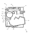
- FIG. 1A is a diagram for explaining the first embodiment, and is a perspective view from one viewpoint of the process cartridge 1, and FIG. 1B is a perspective view from a different viewpoint.
- FIG. 2 is a cross-sectional view of the process cartridge 1.
- FIG. 3 is an exploded perspective view of the process cartridge 1.
- FIG. 4 is an exploded cross-sectional view of the process cartridge 1.
- FIG. 5 is a cross-sectional view for explaining the operation of the process cartridge body 10.
- FIG. 6 is a perspective view of the process cartridge 101 for explaining the second embodiment.
- FIG. 7 is a perspective view of the second member 150 b of the process cartridge protective cover 150.
- 8A is a perspective view of the first member 150a of the process cartridge protective cover 150, and FIG.
- FIG. 8B is a perspective view of the first member 150a of the process cartridge protective cover 150 from different viewpoints.
- FIG. 9 is a cross-sectional view of the process cartridge 101.
- FIG. 10 is a perspective view of the process cartridge 201.
- FIG. 11 is a cross-sectional view of the process cartridge 201.
- FIG. 12 is another cross-sectional view of the process cartridge 201.
- FIG. 13 is an exploded perspective view of the process cartridge 201.
- FIG. 14 is a cross-sectional view for explaining the operation of the process cartridge main body 210.
- FIG. 15 is a perspective view of the separation release means 250.
- 16A is a perspective view of the entire process cartridge 310, and
- FIG. 16B is an enlarged perspective view of one end of the process cartridge.
- FIG. 16A is a perspective view of the entire process cartridge 310
- FIG. 16B is an enlarged perspective view of one end of the process cartridge.
- FIG. 16A is a perspective view of the entire process
- FIG. 17 is a cross-sectional view of the process cartridge 310.
- FIG. 18 is a side view of the process cartridge 310.
- FIG. 19 is a cross-sectional view of the process cartridge 310 in the separated state.
- FIG. 20 is a side view of the process cartridge 310 in the separated state.
- FIG. 21A is a perspective view of the spacing member 341, and
- FIG. 21B is a perspective view of the spacing member 341 '. It is a figure explaining the attitude
- position in which the separation state was maintained by the separation holding member. 6 is a side view when assembling the process cartridge 410.
- FIG. FIG. 24A is a side view showing an example of how to insert the spacing member 460
- FIG. 24B is a side view showing another example of how the spacing member 460 is inserted.
- FIG. 1 is a perspective view of a process cartridge (toner cartridge) 1 having a process cartridge protective cover 50 for explaining the first embodiment.
- FIG. 1A is a perspective view seen from one direction
- FIG. 1B is a perspective view seen from a viewpoint with the bottom side in FIG. 2 is a sectional view taken along the line II-II in FIG. 1A
- FIG. 3 is an exploded perspective view of the process cartridge 1
- FIG. 4 is an exploded sectional view in the same section as FIG. .
- the process cartridge 1 may be described as a process cartridge main body 10 and a process cartridge protective cover 50 (hereinafter simply referred to as “protective cover 50”) disposed on the outer periphery of the process cartridge 1. ).
- protect cover 50 a process cartridge protective cover 50 disposed on the outer periphery of the process cartridge 1.
- the process cartridge main body 10 is a device that is mounted on the image forming apparatus main body to form an image and transfers the image to a recording medium such as paper.
- the structure and function of such a process cartridge main body 10 are known.
- the process cartridge main body 10 has a casing 11, and includes a photosensitive drum 12, a charging roller 13, and developing means 14 inside.
- the housing 11 is a box-shaped member that constitutes the outline of the process cartridge main body 10, and other elements constituting the process cartridge main body 10 are disposed inside the case 11.
- the casing 11 is provided with a window and unevenness communicating with the outside as necessary.
- the window serves as an opening to communicate with the photosensitive drum 12 from the outside because of the need to irradiate the photosensitive drum 12 with laser light and to contact the photosensitive drum 12 with a paper medium or the like.
- Communication parts 11a and 11b which are parts to be formed are formed.
- locking portions 11c and 11d for hooking the locking pieces 51a and 52a of the protective cover 50 are provided.
- the photosensitive drum 12 is a member in which a photosensitive layer is coated on the outer peripheral surface of a cylindrical base. Characters, graphics, and the like to be transferred to a recording medium such as paper are formed on the photosensitive layer.
- the base is formed of a conductive material made of aluminum or aluminum alloy in a cylindrical shape.
- the type of aluminum alloy used for the substrate is not particularly limited, but is a 6000 series, 5000 series, 3000 series aluminum alloy defined by JIS standards (JIS H 4140), which is often used as a substrate of a photosensitive drum. It is preferable that The photosensitive layer is as known.
- the charging roller 13 is one of charging means, and is applied with a voltage.
- the charging roller 13 comes into contact with the photosensitive drum 12 to uniformly charge the photosensitive drum 12.
- the developing means 14 is a means for supplying a developer to the surface of the photosensitive drum 12, and a container 15 in which the developer (toner) is stored and a developing roller 16 provided in the opening of the container 15 are disposed. .
- the well-known other structural member is arrange
- the developing roller 16 is a roller that supplies the developer to the photosensitive drum 12 by causing the developer contained in the container 15 to adhere to the surface thereof and moving the toner to the photosensitive drum 12. As a result, the electrostatic latent image formed on the photosensitive drum 12 is developed.
- a developing roller using a contact developing system is used.
- the developing means 14 has a part of the outer surface of the developing roller 16 on the outer surface of the photosensitive drum 12 as shown in FIG. Positioned to touch. By such contact, the developer (toner) is supplied from the developing roller 16 to the photosensitive drum 12.
- the developing roller 16 is in contact with the photosensitive member during this period. If it is in contact with the drum 12, problems such as deformation or alteration of the contact portion may occur.
- the developing means 14 of the process cartridge body 10 is configured to be able to rotate around a predetermined axis as indicated by an arrow V in FIG.
- the developing roller 16 is urged in a direction in contact with the outer surface of the photosensitive drum 12 as shown in FIG.
- the developing roller 16 can be in a posture of being detached from the photosensitive drum 12 as shown in FIGS.
- the protective cover 50 is configured to be able to maintain this posture.
- the photosensitive drum 12 is irradiated with a laser beam and a recording medium such as paper is brought into contact with the outside. Communication portions 11 a and 11 b that are spaces communicating with the body drum 12 are formed.
- the communication portion 11a and the communication portion 11b are formed on one surface of the process cartridge 1 and the other surface on the opposite side, and both can reach the photosensitive drum 12 from the outside.
- the protective cover 50 includes a first protective piece 51, a second protective piece 52, a connecting piece 53, a separation member 54, and a separation assisting member 55.
- the first protective piece 51 is a plate-like piece arranged so as to conceal the communication portion 11b from the outside as will be described later.
- a protruding locking piece 51a extending toward the second protective piece 52 is formed at one end of the cross section shown in FIGS.
- the second protective piece 52 is a plate-like piece arranged so as to conceal the communication portion 11a from the outside as will be described later, and is separated from the first protective piece 51 with a predetermined interval. It is a piece arranged.
- a protruding locking piece 52 a extending toward the first protective piece 51 is formed at the tip of the second protective piece 52 on the same side as the first protective piece 51.
- the connecting piece 53 includes a tip of the first protective piece 51 opposite to the side on which the locking piece 51a is disposed, and a side of the second protective piece 52 on which the locking piece 52a is disposed. Is a plate-shaped piece arranged so as to connect the tip on the opposite side.
- the separation member 54 is a member that maintains the posture in which the developing roller 16 is separated from the photosensitive drum 12 by rotating the developing unit 14 against the urging force of the developing unit 14 as described later.
- the separation member 54 is a protruding member disposed between the first protection piece 51 and the second protection piece 52, and more specifically, the first protection piece. It is comprised by the taper-shaped member which has the inclined surface arrange
- the separation assisting member 55 is a member that holds the separation state between the photosensitive drum 12 and the developing roller 16 in addition to the separation member 54.
- the separation assisting member 55 of the present embodiment is a member erected from the inner surface of the second protective piece 52, and as can be seen from FIG. 2, in a posture in which the process cartridge body 10 and the protective cover 50 are combined.
- a separation assisting member 55 extends so as to enter between the photosensitive drum 12 and the developing roller 16. Accordingly, even when the separation member 54 does not act for some reason, the separation assisting member 55 can maintain the separation state between the photosensitive drum 12 and the developing roller 16.
- the separation assisting member 55 has an arcuate surface on the photosensitive drum 12 side. Thereby, the surface of the photosensitive drum is not damaged.
- the separation assisting member 55 may be provided at the end of the photosensitive drum where the photosensitive layer is not formed.
- the first protective piece 51 of the protective cover 50 is disposed so as to block the communication portion 11b of the process cartridge body 10. At this time, it arrange
- the second protective piece 52 of the protective cover 50 is disposed so as to block the communication portion 11a of the process cartridge main body 10.
- the locking piece 52 a is disposed so as to be hooked on the locking portion 11 d of the housing 11.
- the connecting piece 53 is positioned on the process cartridge body 10 on the side where the developing means 14 is arranged, and the separating member 54 is arranged to press the developing means 41.
- the developing means 41 rotates as described above, and the developing roller 16 can be in a posture away from the photosensitive drum 12.
- the locking piece 51a is disposed so as to be hooked on the locking portion 11c of the housing 11, and the locking piece 52a is disposed so as to be hooked on the locking portion 11d of the housing 11, so that the separation member Even if 54 receives the urging force from the developing means 41, the posture can be maintained without moving.
- the separation assisting member 55 extends between the photosensitive drum 12 and the developing roller and assists the separation state.
- a hole or a recess may be provided in the casing of the process cartridge body 10 regardless of the purpose.
- the protective cover 50 may further be provided with a protrusion that locks against the hole or the recess. Thereby, the protective cover 50 can be further stably attached to the process cartridge body 10.
- the material of the protective cover 50 is not particularly limited, but is preferably composed of a thin plastic film, for example, a resin such as polyethylene terephthalate or polypropylene. This can be formed by, for example, vacuum forming, pressing, or injection molding.
- the material of the protective cover 50 may be mixed with a so-called ultraviolet scattering agent (such as carbon or ceramic) or an ultraviolet absorber in order to improve the shielding rate of light having a wavelength of 400 nm or less.
- the photosensitive drum, particularly the photosensitive drum, of the process cartridge can be more reliably protected from external defects, and the photosensitive drum and the developing roller can be separated from each other. It is possible to leave.
- FIG. 6 is a perspective view of a process cartridge (toner cartridge) 101 having a process cartridge protective cover 150 for explaining the second embodiment.
- FIG. 6 is a perspective view of the process cartridge 101.
- 7 is a perspective view of the second member 150b of the process cartridge protection cover 150
- FIG. 8A is a perspective view of the first member 150a of the process cartridge protection cover 150 from one viewpoint
- FIG. 8B is a process cartridge protection.
- FIG. 10 is a perspective view of the first member 150a of the cover 150 from another viewpoint.
- FIG. 9 is a cross-sectional view taken along the line IX-IX in FIG.
- the process cartridge 101 is sometimes referred to as a process cartridge main body 10 and a process cartridge protective cover 150 (hereinafter simply referred to as “protective cover 150”). Since the process cartridge body 10 is the same as that of the first embodiment, the same reference numerals are given and the description thereof is omitted here.
- the protective cover 150 has a box-shaped first member 150a opened on one side and a box-shaped second member 150b opened on one side, and the opened parts of the two members overlap each other. As a result, a box-like shape is formed, and the process cartridge main body 10 is contained therein. In such a state of being combined in a box shape, the protective cover 150 includes a first protective piece 151, a second protective piece 152, a first connecting piece 153, a second connecting piece 154, and a separation member. 155.
- the first protective piece 151 is a plate-like piece arranged so as to conceal the communication part 11b from the outside.
- the first protective piece 151 is constituted by a box-shaped bottom plate of the first member 150a.
- the second protective piece 152 is a plate-like piece arranged so as to conceal the communication part 11a from the outside. That is, the second protective piece 152 is a plate-like piece that is spaced apart from the first protective piece 151 with a predetermined interval. In this embodiment, the second protective piece 152 is constituted by a box-shaped bottom plate of the second member 150b. From the surface of the second protective piece 152, a position restricting piece 152 a that protrudes toward the first protective piece 151 is formed in the cross section shown in FIG. 9.
- the first connecting piece 153 is a plate-like piece arranged so as to connect one end of the first protective piece 151 and one end of the second protective piece 152.
- the first connecting piece 153 is formed by abutting the end faces of the box-shaped side plate of the first protective piece 151 and the box-shaped side plate of the second protective piece 152. Is formed.
- the second connecting piece 154 is a plate-like piece arranged so as to connect the other side end of the first protective piece 151 and the other side end of the second protective piece 152.
- the second connecting piece 154 is a connecting piece arranged on the opposite side of the first connecting piece 153.
- the box-shaped side plate of the first protective piece 151 and the second protective piece 152 It is formed by abutting end faces of one box-like side plate.
- the separating member 155 is a protruding member that rotates the developing unit 14 against the urging force of the developing unit 14 and maintains the posture in which the developing roller 16 is separated from the photosensitive drum 12.
- the separation member 155 is disposed between the first protection piece 151 and the second protection piece 152 as shown in FIG. 9, and more specifically, the first protection piece 151 and the first connection piece 153. It is comprised by the taper-shaped member which has the inclined surface arrange
- the spacing member 155 of this embodiment is provided with three spacing members 155 intermittently along the longitudinal direction of the protective cover 150. However, it is not always necessary to dispose a plurality of elements intermittently, and a single continuous element may be used.
- FIG. 9 clearly shows the mode of the combination.
- the first protective piece 151 of the protective cover 150 is disposed so as to block the communication portion 11b of the process cartridge body 10. At this time, it arrange
- the second protective piece 152 of the protective cover 150 is disposed so as to block the communication portion 11a of the process cartridge main body 10.
- the position restricting piece 152a presses the housing 11 toward the first protective piece 151 side.
- both the communication part 11a and the communication part 11b are concealed by the first protective piece 151 and the second protective piece 152, respectively, and the photosensitive drum 12 is more reliably protected.
- the first connecting piece 153 is positioned on the process cartridge main body 10 on the side where the developing means 14 is disposed, and the separating member 155 is disposed so as to press the developing means 41.
- the developing unit 14 rotates as described above, and the developing roller 16 can be in a posture away from the photosensitive drum 12.
- a second connection piece 154 is disposed on the side opposite to the first connection piece 153. Therefore, since the process cartridge main body 10 is surrounded by members on the four sides and is pressed, even if the separating member 155 receives the urging force from the developing means 14, the posture can be maintained without moving.
- the material of the protective cover 150 is not particularly limited, but is preferably composed of a thin plastic film, for example, a resin such as polyethylene terephthalate or polypropylene. This can be formed by, for example, vacuum forming, pressing, or injection molding. Further, the material of the protective cover 50 may be mixed with a so-called ultraviolet scattering agent (such as carbon or ceramic) or an ultraviolet absorber in order to improve the shielding rate of light having a wavelength of 400 nm or less.
- a so-called ultraviolet scattering agent such as carbon or ceramic
- an ultraviolet absorber in order to improve the shielding rate of light having a wavelength of 400 nm or less.
- the protective cover 150 and the process cartridge 101 including the protective cover 150 can more reliably protect the photosensitive drum, particularly the photosensitive drum, of the process cartridge from external defects, and keep the photosensitive drum and the developing roller apart. It is possible.
- FIGS. 10 to 15 are views for explaining the third embodiment
- FIG. 10 is a perspective view of a process cartridge (toner cartridge) 201 provided with the separation releasing means 250.
- 11 is a cross-sectional view taken along the line II-II in FIG. 10
- FIG. 12 is a cross-sectional view taken along the line III-III in FIG. 1
- FIG. 13 is a process according to the viewpoint of FIG. An exploded sectional view of the cartridge 201 is shown.
- the process cartridge 201 includes a process cartridge main body 210 and a separation releasing means 250 disposed on the outer periphery of the process cartridge 201.
- the process cartridge main body 210 is a device that is mounted on the main body of the image forming apparatus to form an image and transfers the image to a recording medium such as paper.
- the structure and function of such a process cartridge main body 210 are known.
- the process cartridge main body 210 has a casing 211 and includes a photosensitive drum 212, a charging roller 213, a developing means 214, and a separation member 220 inside. Yes.
- the housing 211 is a box-shaped member that forms the outer shell of the process cartridge main body 210, and other elements that constitute the process cartridge main body 210 are disposed inside the housing 211.
- the casing 211 is provided with a window and unevenness communicating with the outside as necessary.
- the window is formed with a communicating portion 211a that is a portion communicating with the photosensitive drum 212 from the outside because the photosensitive drum 212 needs to contact a paper medium or the like.
- a locking portion 211b for hooking the locking piece 251a of the separation releasing means 250 is provided.
- the photosensitive drum 212 is a member in which a photosensitive layer is coated on the outer peripheral surface of a cylindrical base. Characters, graphics, and the like to be transferred to a recording medium such as paper are formed on the photosensitive layer.
- the base is formed of a conductive material made of aluminum or aluminum alloy in a cylindrical shape.
- the type of aluminum alloy used for the substrate is not particularly limited, but is a 6000 series, 5000 series, 3000 series aluminum alloy defined by JIS standards (JIS H 4140), which is often used as a substrate of a photosensitive drum. It is preferable that The photosensitive layer is as known.
- the charging roller 213 is one of charging means, and is applied with a voltage.
- the charging roller 213 contacts the photosensitive drum 212 and uniformly charges the photosensitive drum 212.
- the developing unit 214 is a unit that supplies a developer to the surface of the photosensitive drum 212, and includes a container 215 that stores the developer (toner) and a developing roller 216 that is provided in an opening of the container 215. .
- the developing roller 216 is a roller that supplies the developer to the photosensitive drum 212 such that the developer contained in the container 215 adheres to the surface and moves the toner to the photosensitive drum 212. As a result, the electrostatic latent image formed on the photosensitive drum 212 is developed.
- a developing roller using a contact developing system is used.
- the separation member 220 is disposed on one end side of the developing roller 216 and is provided so as to be rotatable coaxially with the rotation shaft of the developing roller 216. As can be seen from FIG. 11, the separation member 220 is disposed between the developing roller 216 and the photosensitive drum 212, with one end contacting the photosensitive drum 212 and the other end contacting the developing roller 216. It is sandwiched and kept in a separated state.
- the separation member 220 is provided with a release protrusion 220 a, and pulling this rotates the separation member 220, and the separation member 220 is connected to the developing roller 216 and the photosensitive drum 212. The state where the two members are separated from each other is resolved.
- the developing unit 214 is configured so that a part of the outer surface of the developing roller 16 contacts the outer surface of the photosensitive drum 12 as shown in FIG. 14 in a state where the process cartridge main body 210 is mounted on the apparatus main body. Is positioned. By such contact, the developer (toner) is supplied from the developing roller 216 to the photosensitive drum 212. At this time, the separation member 220 is in a posture in which the separation member 220 is detached from between the developing roller 216 and the photosensitive drum 212.
- the developing roller 216 is in the photosensitive drum 212 during this period. If it is in contact with the surface, problems such as deformation or alteration of the contact portion may occur.
- the developing means 214 of the process cartridge main body 210 is configured to be rotatable about a predetermined axis as indicated by an arrow V in FIG. Then, as shown in FIG. 14, the developing roller 216 is biased in a direction in contact with the outer surface of the photosensitive drum 212. On the other hand, when the developing means 214 is rotated against the urging force and the separation member 220 is sandwiched between the developing roller 216 and the photosensitive drum 212, the developing roller 216 is moved as shown in FIGS. The posture can be taken away from the photosensitive drum 212.
- FIG. 15 is a perspective view of the separation release means 250.
- the separation release means 250 includes a protection piece 251, a holding piece 252, and a separation release member 260.
- the holding piece 252 also functions as a holding member for holding the separation releasing means 250 in the process cartridge main body 210.
- the holding piece 252 is a plate-like piece provided at the end of the protective piece 251 opposite to the locking piece 251a and extending toward the process cartridge main body 210 in the cross section shown in FIGS. is there.
- the holding piece 252 is hooked on any part of the process cartridge main body 210 and acts together with the locking piece 251 a to hold the separation releasing means 250 in the process cartridge main body 210.
- the front end of the holding piece 252 comes into contact with and catches on the container 215 provided in the developing unit 214.
- the separation release member 260 is a member provided so as to extend from the surface of the protective cartridge 251 on the process cartridge main body 210 side. Further, as can be seen from FIG. 12, the separation releasing member 260 is formed such that the tip thereof is tapered from the root portion on the protective piece 251 side. As can be seen from FIG. 15, the separation release member 260 is provided at the end of the protection piece 251, and this corresponds to the position of the release protrusion 220 a of the separation member 20 of the process cartridge body 210. As shown in FIG. 12, the tip of the separation release member 260 is disposed so as to be caught by the release protrusion 220a of the separation member 220.
- a hole or a recess may be provided in the casing of the process cartridge main body 210 regardless of the purpose.
- the separation release means 250 may further be provided with a protrusion that locks against the hole or the recess. Thus, the separation releasing means 250 can be stably attached to the process cartridge main body 210.
- process cartridge body 210 and the separation release means 250 as described above are combined as follows to form the process cartridge 1. 10 to 12 clearly show the mode of the combination.
- the protective piece 251 of the separation releasing means 250 is arranged so as to block the communication portion 211 a of the process cartridge main body 210. At this time, it arrange
- the holding piece 252 of the separation releasing means 250 is hooked on the container 215 of the developing means 214, and the separation releasing means 250 is held on the process cartridge main body 210 by the locking piece 251a and the holding piece 252.
- the communication portion 211a is concealed by the protection piece 251 and the photosensitive drum 212 is protected from light, dust, dust, scratches, and the like.
- the separation release member 260 is disposed such that the tip thereof is caught by the release protrusion 220a of the separation member 220.
- the separating member 220 is disposed between the photosensitive drum 212 and the developing roller 216, and both are separated as shown in FIGS.
- the separation releasing means 250 is detached from the process cartridge main body 210. Then, the separation release member 260 is caught by the release protrusion 220a of the separation member 220 at the time of the separation, and the separation member 220 is rotated. As a result, the process cartridge main body 210 is in a state where the developing means 214 can rotate and the developing roller 216 can come into contact with the photosensitive drum 212 as shown in FIG.
- the separation state between the developing roller 216 and the photosensitive drum 212 can be eliminated before the process cartridge main body 210 is mounted on the apparatus main body. Can be activated.
- the separation release means of this embodiment can perform protection and separation release simultaneously. Then, it is possible to simultaneously remove the protective cover and release the separation by one operation.
- the present invention is not limited to this configuration, and may be a separation release unit that functions only to release separation without adding a protection function. In that case, it is only necessary to provide a separation releasing member and a holding member for holding the separation releasing member in the process cartridge main body 210.
- the protection piece 251, the locking piece 251a, and the holding piece 252 function as the holding member.
- FIG. 16 is a perspective view of a process cartridge (toner cartridge) 310 for explaining the fourth embodiment.
- FIG. 16A is a perspective view of the entire process cartridge 310
- FIG. 16B is an enlarged perspective view focusing on one end portion thereof.
- FIG. 17 is a cross-sectional view taken along the line II-II in FIG. 16A
- FIG. 18 is a side view seen from the direction of the arrow indicated by III in FIG. In FIG. 18, a portion hidden by the first housing 320 in the outline of the second housing 330 is represented by a dotted line.
- the process cartridge 310 includes a photosensitive drum 311 and a charging roller 312 that is adjacent to the photosensitive drum 311 and is a means for charging the photosensitive drum 311. Further, a cleaning blade 313 is provided as means for cleaning the surface of the charging roller 312.
- a developing roller 314 as developing means is provided so as to face the photosensitive drum 311, and a developing blade 315 and a toner supply roller 316 are disposed so as to contact the developing roller 314.
- An agitator 317 is provided so as to contact the toner supply roller 316, and one end of the agitator 317 is connected to a rotating shaft 318 that rotates the agitator 317.
- a toner storage container 319 for storing toner is provided.
- the rotation of the agitator 317 makes contact with the toner storage container 319, thereby giving an impact to the toner storage container 319, promoting the flow of toner disposed in the toner storage container 319, and supplying the toner to the toner storage container 319. It has a function to make it easy to discharge from
- the process cartridge 310 is held by each member surrounded by the first casing 320 and the second casing 330.
- the first casing 320 is provided with the above-described photosensitive drum 311, charging roller 312, and cleaning blade 313.
- the first casing 320 is provided with end plates 321 and 322 at both ends thereof.
- the end plate 321 is provided with a through hole (hole) 321a and a protrusion 321b.
- the through hole 321 a is a hole provided so as to penetrate the end plate 321 and opens in a direction facing the end plate 322.
- the protrusion 321 b is a protrusion protruding from a surface of the end plate 321 that is opposite to the end plate 322.
- developing roller 314, developing blade 315, toner supply roller 316, agitator 317, rotating shaft 318, and toner storage container 319 are disposed in the second casing 330.
- a protrusion 331 is provided at the end of the second housing 330.
- the first casing 320 and the second casing 330 as described above are combined as follows. That is, as can be seen from FIG. 16A, the second casing 330 is disposed between the two end plates 321 and 322 of the first casing 320, and the second casing 330 can be rotated about a shaft (not shown).
- the second housing 330 is arranged to pass the end plate 321 and the end plate 322 of the first housing 320.
- the protrusion 331 provided in the second housing 330 is disposed so as to pass through the through hole 321a provided in the end plate 321 of the first housing 320. 16A, FIG. 16B, and FIG. 18, the protrusion 321b provided on the end plate 321 of the first housing 320 and the second housing 330 are provided.
- An elastic member 340 is disposed so as to pass the protrusion 331.
- the second housing 330 is biased in the rotation direction. This direction is an urging direction in which the photosensitive drum 311 and the developing roller 314 are held in contact with each other as shown in FIG.
- the protrusion 331 may have a function in addition to being used for separation. For example, it can be configured to function as an electrode.
- FIG. 19 and 20 are diagrams for explaining a scene where the second casing 330 is rotated.
- 19 is a sectional view from the same viewpoint as FIG. 17, and
- FIG. 20 is a side view from the same viewpoint as FIG.
- a portion hidden by the first housing 320 in the outline of the second housing 330 is represented by a dotted line.
- the photosensitive drum 311 and the developing roller 314 can be separated from each other by rotating the second housing 330 against the urging force of the elastic member 340.
- the position of the protrusion 331 provided on the second housing 330 changes inside the through hole 321 a provided on the end plate 321 of the first housing 320.
- a space at a position indicated by V in FIG. 20 (a space on the right side of the protrusion 331 in FIG. 20) is expanded.
- the present invention is a separation method for maintaining a separated posture (the posture shown in FIGS. 19 and 20) by inserting a separation holding member into the space.
- FIG. 21 shows an example of the separation holding member.
- FIG. 21A is a perspective view of a spacing member 341 of one example
- FIG. 21B is a perspective view of a spacing member 341 'of another example.
- the separation holding members 341 and 341 ' have a columnar insertion portion 342.
- the separation holding member 341 ′ further includes a knob 343, which improves the usability of the separation holding member.
- the insertion portions 342 of the separation holding members 341 and 341 ′ are separated from the protrusions 331 of the second housing 330 and the through holes 321 a of the first housing 320 in the separation state. Insert between walls. Accordingly, the protrusion 331 is caught by the insertion portion 342 of the separation holding members 341 and 341 ′ and cannot move, so that the separation state is maintained.
- the end plate 321 is disposed in the first housing 320, the through hole 321a is provided therein, and the protrusion 331 is provided in the second housing 330.
- an end plate may be arranged in the second housing, a hole may be provided here, and a protrusion may be provided in the first housing. This also works in the same way.
- FIG. 23 and 24 are diagrams for explaining the fifth embodiment, and are side views of the process cartridge (toner cartridge) 410.
- FIG. In this embodiment, when assembling the process cartridge 410, the end of the first housing 420 containing the photosensitive drum 411 and the end of the second housing 430 containing the developing roller 414 as shown in FIG. The process of attaching the cover member 440 on the flat plate is included.
- the second casing 430 is provided with a protrusion 431 and a protrusion 432 at the end that is a side surface so as to protrude outward.
- the cover member 440 has a first hole (hole) 441 in the upper portion and a second hole (hole) 442 in the lower portion, and a protruding portion 443 is provided to protrude outward. 23, when the cover member 440 is attached to the end portion of the first housing 420 and the end portion of the second housing 430, the protrusion 431 and the protrusion 431 of the second housing 430 protrude.
- the part 432 is disposed inside the second hole 442 of the cover member 440 and protrudes from the second hole 442.
- both ends of the elastic member 450 made of a spring are attached so as to be hooked by the protruding portion 432 of the second housing 430 and the protruding portion 443 of the cover member 440, respectively.
- the contact state between the body drum 411 and the developing roller 414 is realized.
- a predetermined spacing holding member is attached to the process cartridge 410 from the outside of the cover member 440.
- FIG. 24 (a) shows one example.
- the second housing 430 is held so as to be rotatable relative to the first housing 420 and the cover member 440. That is, the operator can rotate the second housing 430 in the direction of the arrow indicated by X against the inelastic force of the elastic member 450. At this time, the developing roller 414 is separated from the photosensitive drum 411.
- the operator separates between the second hole 442 provided in the cover member 440 and the protrusion 431 protruding from the second housing 430 disposed inside the second hole 442.
- the holding member 460 is inserted.
- the spacing member 460 is held and fixed in a space defined between the inner wall of the second hole 442 and the protrusion 431.
- a process cartridge separation method for separating the photosensitive drum 411 and the developing roller 414 is realized.
- the process cartridge 410 is in the state on the right side of FIG. 23 and can be used by being attached to the apparatus main body.
- the fixed separation holding member 460 prevents the attachment to the apparatus main body, the process cartridge 410 is prevented from being attached to the apparatus main body while the separation state between the developing roller 414 and the photosensitive drum 411 is maintained. It has a function.
- the shape of the separation holding member 460 is not particularly limited, as shown in FIG. 24A, insertion and removal are facilitated by providing a handle 461.
- the protrusion 431 is disposed on the second housing 430, and the separation holding member 460 is held between the protrusion 431 and the second hole 442 of the cover member 440.
- a protrusion 431 may be disposed on the first housing 420, and the spacing member 460 may be inserted between the protrusion 431 and the second hole 442 of the cover member 440.
- the protrusion 432 is also disposed in the first housing 420, and both ends of the elastic member 450 are hooked on the protrusion 432 disposed in the first housing 420 and the protrusion 443 of the cover member 440.
- the first housing 420 is held so as to be relatively rotatable with respect to the second housing 430 and the cover member 440. Further, the position of the second hole 442 of the cover member 440 is adjusted so that the protrusion 431 of the first housing 420 is disposed inside thereof.
- FIG. 24B shows another example.
- the operator inserts the separation holding member 460 into the first hole 441 provided in the cover member 440.
- the spacing member 460 passes through the first hole 441 and contacts a part of the second housing 430, thereby resisting the urging force of the elastic member 450.
- the rotation returning to FIG. 23 is prevented.
- a process cartridge separation method for separating the photosensitive drum 411 and the developing roller 414 is realized.
- the process cartridge 410 is in the state on the right side of FIG. 23 and can be used by being attached to the apparatus main body.
- the process cartridge 410 since the fixed separation holding member 460 prevents the attachment to the apparatus main body, the process cartridge 410 is prevented from being attached to the apparatus main body while the separation state between the developing roller 414 and the photosensitive drum 411 is maintained. It has a function.
- the shape of the separation holding member 460 is not particularly limited, as shown in FIG. 24 (a) or FIG. 24 (b), by providing a handle 461, insertion and removal are facilitated.
- the separation holding member 460 preferably has a shape that does not touch the developing roller 414 and the photosensitive drum 411 in the separation state.
- the separation holding member 460 is in contact with a part of the second housing 430 while passing through the first hole 441, thereby resisting the urging force of the elastic member 450.
- the rotation of the housing 430 back to FIG. 23 is prevented.
- the separation holding member 460 that has passed through the first hole 441 contacts a part of the first housing 420, thereby resisting the urging force of the elastic member 450.
- the rotation of 420 back to FIG. 23 may be prevented.
- the protrusion 432 is also disposed in the first housing 420, and both ends of the elastic member 450 are hooked on the protrusion 432 disposed in the first housing 420 and the protrusion 443 of the cover member 440.
- the first housing 420 is held so as to be relatively rotatable with respect to the second housing 430 and the cover member 440. Further, the position of the first hole 441 of the cover member 440 is adjusted so that the separation holding member 460 that has passed through the first hole 441 can contact a part of the first housing 420.
Landscapes
- Engineering & Computer Science (AREA)
- Computer Vision & Pattern Recognition (AREA)
- Physics & Mathematics (AREA)
- General Physics & Mathematics (AREA)
- Electrophotography Configuration And Component (AREA)
Abstract
A processing cartridge protective cover (50, 150) disposed on the outer periphery of a processing cartridge body (10) comprises: a plate-like first protective piece (51, 151), a plate-like second protective piece (52, 152) positioned facing the first protective piece with a gap therebetween; a connecting piece (53, 153) that connects one edge of the first protective piece and one edge of the second protective piece; engaging pieces (51a, 52a, 151a), which are protruding members disposed on at least the first protective piece or the second protective piece; and a separation member (54, 155), which is a protrusion disposed between the first protective piece and the second protective piece, on at least one of the first protective piece, the second protective piece, and the connecting piece.
Description
本発明は、プロセスカートリッジを保護する保護カバー、及び当該保護カバーが装着されたプロセスカートリッジ、ならびにプロセスカートリッジの離間解除手段等、に関する。
The present invention relates to a protective cover for protecting a process cartridge, a process cartridge to which the protective cover is attached, a separation release means for the process cartridge, and the like.
レーザープリンタ、複写機等の画像形成装置には、該画像形成装置の本体(以下、「装置本体」と記載することがある。)に対して着脱可能にプロセスカートリッジが備えられている。
2. Description of the Related Art Image forming apparatuses such as laser printers and copiers are provided with a process cartridge that is detachable from a main body of the image forming apparatus (hereinafter sometimes referred to as “apparatus main body”).
プロセスカートリッジは、装置本体に装着された姿勢で文字や図形等、表されるべき内容を形成し、これを紙等の記録媒体に転写する部材である。そのために、プロセスカートリッジには、転写する内容が形成される感光体ドラム、及び該感光体ドラムに対してトナーを供給する現像ローラが具備されている。当該プロセスカートリッジが装着された画像形成装置により画像が形成される原理は公知の通りである。
The process cartridge is a member that forms contents to be represented such as characters and figures in a posture mounted on the apparatus main body, and transfers this to a recording medium such as paper. For this purpose, the process cartridge includes a photosensitive drum on which the content to be transferred is formed, and a developing roller that supplies toner to the photosensitive drum. The principle that an image is formed by the image forming apparatus to which the process cartridge is mounted is well known.
プロセスカートリッジは交換部品であるため、プロセスカートリッジ単体で輸送、販売、取り付けが行われる。従って、装置本体に装着される前までにプロセスカートリッジを構成する部材を保護することが重要となる。例えば特許文献1、特許文献2にはプロセスカートリッジに対して装着され、装置本体に取り付けられる際には離脱される保護カバーが開示されている。これによりプロセスカートリッジを構成する各部材を光、ゴミ等から保護している(特許文献1,2参照)。
Since the process cartridge is a replacement part, it is transported, sold and installed as a single process cartridge. Therefore, it is important to protect the members constituting the process cartridge before being attached to the apparatus main body. For example, Patent Document 1 and Patent Document 2 disclose a protective cover that is attached to a process cartridge and is removed when the process cartridge is attached to the apparatus main body. Thereby, each member constituting the process cartridge is protected from light, dust and the like (see Patent Documents 1 and 2).
また、プロセスカートリッジにおいて、現像ローラは、プロセスカートリッジが装置本体に装着されているときには感光体ドラムに接触して作動するが、プロセスカートリッジが装置本体に未だ装着されていないときには、感光体ドラムには接触することなく離しておくことが好ましい。そこで、プロセスカートリッジには、装置本体に装着する前には感光体ドラムと現像ローラを離隔させておくための離間手段が設けられる。
Further, in the process cartridge, the developing roller operates in contact with the photosensitive drum when the process cartridge is mounted on the apparatus main body, but when the process cartridge is not yet mounted on the apparatus main body, It is preferable to keep away without contacting. Therefore, the process cartridge is provided with a separation means for separating the photosensitive drum and the developing roller before being attached to the apparatus main body.
特許文献3には、感光体ドラムと現像ローラとを離しておく(離間状態とする)部材において、プロセスカートリッジを装置本体に装着し、感光体ドラムが回転することにより当該部材が回動して離間状態が解除される技術が開示されている。
In Patent Document 3, in a member that keeps the photosensitive drum and the developing roller apart (set to a separated state), the process cartridge is mounted on the apparatus main body, and the photosensitive drum rotates to rotate the member. A technique for releasing the separated state is disclosed.
しかしながら、特許文献1、2に記載の先行技術では、必ずしも保護が十分とは言えず、感光体ドラムに対して外光が直接照射してしまう虞があった。
However, in the prior arts described in Patent Documents 1 and 2, the protection is not necessarily sufficient, and there is a possibility that external light may be directly irradiated onto the photosensitive drum.
また、特許文献3に記載の離間部材では、プロセスカートリッジが装置本体に装着され、感光体ドラムが回転しないと離間状態が解消されなかった。さらに、感光体ドラムが回転する際の摩擦力だけでは離間を解除できないことがあり、感光体ドラムの端部に装着する端部部材に凹部の押圧部を設けなければ確実な離間解除ができないことがある。また、端部部材に凹部を設ける場合、金型の構造が複雑になる上、端部部材の真円度が悪化し、画像に影響が出る虞がある。これに対してプロセスカートリッジを装置本体に装着する前に離間状態を解消することが望まれていた。
Further, in the separation member described in Patent Document 3, the separation state cannot be resolved unless the process cartridge is mounted on the apparatus main body and the photosensitive drum rotates. Furthermore, separation may not be released only by the frictional force when the photosensitive drum rotates, and reliable separation cannot be released unless the end member attached to the end of the photosensitive drum is provided with a pressing portion of a recess. There is. Further, when the concave portion is provided in the end member, the structure of the mold is complicated, and the roundness of the end member is deteriorated, which may affect the image. On the other hand, it has been desired to eliminate the separation state before the process cartridge is mounted on the apparatus main body.
また、特許文献3に記載の技術を含め、従来の当該状態とするための技術は複雑になる傾向にあった。これに対してもっと簡易に離間状態を維持することができれば、プロセスカートリッジの製造自体が簡易となる。
In addition, the techniques for achieving the conventional state, including the technique described in Patent Document 3, tend to be complicated. On the other hand, if the separated state can be maintained more easily, the process cartridge can be manufactured easily.
そこで本発明は上記問題点に鑑み、より確実に外光やゴミなどからの保護を可能するとともに、感光体ドラムと現像ローラとを離間させることができる手段や、離間状態を解除し得る手段を提供することを課題とする。また、これらの手段が用いられたプロセスカートリッジを提供する。
Accordingly, in view of the above problems, the present invention provides a means that can more reliably protect against external light and dust, and that can separate the photosensitive drum and the developing roller, and a means that can release the separated state. The issue is to provide. Further, a process cartridge using these means is provided.
本発明は、プロセスカートリッジ本体の外周部に配置されるプロセスカートリッジ保護カバーであって、板状の第一の保護片と、第一の保護片に対して間隔を有して対向して配置される板状の第二の保護片と、第一の保護片と第二の保護片との一端同士を連結する連結片と、第一の保護片及び第二の保護片の少なくとも一方に配置された突起状部材である係止片と、第一の保護片、第二の保護片、及び連結片の少なくとも一つに、第一の保護片と第二の保護片との間に配置される突起である離間部材と、を備える、プロセスカートリッジ保護カバーである。
The present invention is a process cartridge protective cover disposed on the outer peripheral portion of a process cartridge main body, and is disposed opposite to the plate-shaped first protective piece and the first protective piece with a space therebetween. A plate-shaped second protective piece, a connecting piece for connecting ends of the first protective piece and the second protective piece, and at least one of the first protective piece and the second protective piece. At least one of the locking piece that is the protruding member, the first protective piece, the second protective piece, and the connecting piece is disposed between the first protective piece and the second protective piece. And a separation member that is a protrusion.
本発明のプロセスカートリッジ保護カバーの一態様として、例えば、少なくとも2つの部材を組み合わせることにより第一の保護片、第二の保護片、及び連結片が形成される。
As one aspect of the process cartridge protective cover of the present invention, for example, a first protective piece, a second protective piece, and a connecting piece are formed by combining at least two members.
本発明のプロセスカートリッジ保護カバーの一態様として、例えば、第一の保護片、第二の保護片、及び連結片の少なくとも一つに、プロセスカートリッジ本体の感光体ドラムと現像ローラとの間に配置されるべき突起である離間補助部材が配置されている。
As one aspect of the process cartridge protective cover of the present invention, for example, at least one of the first protective piece, the second protective piece, and the connecting piece is disposed between the photosensitive drum of the process cartridge main body and the developing roller. A separation assisting member that is a protrusion to be made is disposed.
本発明のプロセスカートリッジ保護カバーの一態様として、例えば、離間補助部材のうち前記感光体ドラム側に対向するべき面は円弧状である。本発明は、筐体、並びに該筐体内に配置された感光体ドラム、及び現像手段を備えるプロセスカートリッジであって、外周に本発明のプロセスカートリッジ保護カバーが配置され、プロセスカートリッジ保護カバーの係止片が筐体に具備された係止部に係止され、第一の保護片、及び第二の保護片が筐体に設けられた開口部を塞いでおり、離間部材が現像手段に接触することで、現像手段の現像ローラと感光体ドラムが接触することなく離れて配置されている、プロセスカートリッジである。
As one aspect of the process cartridge protective cover of the present invention, for example, the surface of the separation assisting member that should face the photosensitive drum side has an arc shape. The present invention is a process cartridge including a housing, a photosensitive drum disposed in the housing, and a developing unit. The process cartridge protective cover of the present invention is disposed on the outer periphery, and the process cartridge protective cover is locked. The piece is locked to the locking portion provided in the housing, the first protective piece and the second protective piece block the opening provided in the housing, and the separating member contacts the developing means. Thus, the process cartridge is arranged such that the developing roller of the developing unit and the photosensitive drum are separated from each other without contact.
本発明のプロセスカートリッジの一態様として、例えば、保護カバーには、筐体に具備された穴又は凹部に係止する突起がさらに設けられている。
As one aspect of the process cartridge of the present invention, for example, the protective cover is further provided with a protrusion that engages with a hole or a recess provided in the housing.
本発明は、プロセスカートリッジ本体に配置され、感光体ドラム及び現像ローラの離間状態を解除する離間解除手段であって、プロセスカートリッジ本体の外周部に配置される保持部材と、保持部材から延びるように設けられ、感光体ドラム及び現像ローラとの間に具備された離間部材に引っ掛かって配置される離間解除部材と、を備える、離間解除手段である。
The present invention is a separation release unit that is arranged in a process cartridge body and releases a separation state of a photosensitive drum and a developing roller, and a holding member arranged on an outer peripheral portion of the process cartridge body, and extends from the holding member A separation release member provided between the photosensitive drum and the developing roller and arranged to be caught by the separation member.
本発明の離間解除手段の一態様として、例えば、保持部材が、板状の保護片と、該保護片の一端に配置された係止片と、を備える。
As one mode of the separation release means of the present invention, for example, the holding member includes a plate-shaped protective piece and a locking piece arranged at one end of the protective piece.
本発明は、筐体、並びに該筐体内に配置された感光体ドラム、及び現像手段を備えるプロセスカートリッジであって、感光体ドラムと現像手段との間には離間部材が配置されており、本発明の離間解除手段を具備し、離間解除部材は、離間部材に引っ掛かって配置されているプロセスカートリッジである。
The present invention is a process cartridge including a casing, a photosensitive drum disposed in the casing, and a developing unit. A separation member is disposed between the photosensitive drum and the developing unit. The separation releasing member of the invention is provided, and the separation releasing member is a process cartridge arranged to be hooked on the separation member.
本発明のプロセスカートリッジの一態様として、例えば、離間解除手段には、筐体に具備された穴又は凹部に係止する突起がさらに設けられている。
As one aspect of the process cartridge of the present invention, for example, the separation release means is further provided with a protrusion that is engaged with a hole or a recess provided in the housing.
本発明は、付勢力により接触状態となる感光体ドラムと現像ローラとの離間状態を維持する方法であって、感光体ドラムを内包する第一の筐体に回動可能に保持された、現像ローラを内包する第二の筐体を付勢力に抗して離間させる過程と、第一の筐体の端部に設けられた穴と、該穴の内側に配置される第二の筐体から突出する突起と、の間に、離間保持部材を差し込む過程と、を含む、プロセスカートリッジの離間方法である。
The present invention is a method for maintaining a separation state between a photosensitive drum and a developing roller that are brought into contact with each other by an urging force, and is a development that is rotatably held in a first housing containing the photosensitive drum. A process of separating the second housing containing the rollers against the urging force, a hole provided at an end of the first housing, and a second housing disposed inside the hole. A process cartridge separation method including a step of inserting a separation holding member between the protruding protrusions.
本発明は、付勢力により接触状態となる感光体ドラムと現像ローラとの離間状態を維持する方法であって、感光体ドラムを内包する第一の筐体に回動可能に保持された、現像ローラを内包する第二の筐体を付勢力に抗して離間させる過程と、第二の筐体の端部に設けられた穴と、該穴の内側に配置される第一の筐体から突出する突起と、の間に、離間保持部材を差し込む過程と、を含む、プロセスカートリッジの離間方法である。
The present invention is a method for maintaining a separation state between a photosensitive drum and a developing roller that are brought into contact with each other by an urging force, and is a development that is rotatably held in a first housing containing the photosensitive drum. A process of separating the second housing containing the rollers against the urging force, a hole provided at an end of the second housing, and a first housing disposed inside the hole. A process cartridge separation method including a step of inserting a separation holding member between the protruding protrusions.
本発明は、付勢力により接触状態となる感光体ドラムと現像ローラとの離間状態を維持する方法であって、前記感光体ドラムを内包する第一の筐体の端部と、前記現像ローラを内包する第二の筐体の端部に、カバー部材を取り付ける過程と、前記第一の筐体に対し、相対的に回動可能に保持された、前記第二の筐体を前記付勢力に抗して離間させる過程と、前記カバー部材に設けられた穴と、該穴の内側に配置される前記第二の筐体から突出する突起と、の間に、離間保持部材を差し込む過程と、を含む。
The present invention is a method for maintaining a separated state of a photosensitive drum and a developing roller that are brought into contact with each other by an urging force, and includes an end portion of a first housing enclosing the photosensitive drum, and the developing roller. The process of attaching a cover member to the end of the second housing that encloses, and the second housing, which is held rotatably relative to the first housing, to the biasing force A process of inserting the separation holding member between the process of separating against and the hole provided in the cover member and the protrusion protruding from the second housing disposed inside the hole; including.
本発明は、付勢力により接触状態となる感光体ドラムと現像ローラとの離間状態を維持する方法であって、前記感光体ドラムを内包する第一の筐体の端部と、前記現像ローラを内包する第二の筐体の端部に、カバー部材を取り付ける過程と、前記第二の筐体に対し、相対的に回動可能に保持された、前記第一の筐体を前記付勢力に抗して離間させる過程と、前記カバー部材に設けられた穴と、該穴の内側に配置される前記第一の筐体から突出する突起と、の間に、離間保持部材を差し込む過程と、を含む。
The present invention is a method for maintaining a separated state of a photosensitive drum and a developing roller that are brought into contact with each other by an urging force, and includes an end portion of a first housing enclosing the photosensitive drum, and the developing roller. The process of attaching a cover member to the end of the second housing that encloses, and the first housing that is held rotatably relative to the second housing to the biasing force A process of inserting the spacer holding member between the hole provided in the cover member and the protrusion protruding from the first housing disposed inside the hole; including.
本発明は、付勢力により接触状態となる感光体ドラムと現像ローラとの離間状態を維持する方法であって、前記感光体ドラムを内包する第一の筐体の端部と、前記現像ローラを内包する第二の筐体の端部に、カバー部材を取り付ける過程と、前記第一の筐体に対し、相対的に回動可能に保持された、前記第二の筐体を前記付勢力に抗して離間させる過程と、前記カバー部材に設けられた穴を通過し、前記第二の筐体の一部に接触して、前記付勢力に抗して前記第二の筐体の回動を阻止する離間保持部材を差し込む過程と、を含む。
The present invention is a method for maintaining a separated state of a photosensitive drum and a developing roller that are brought into contact with each other by an urging force, and includes an end portion of a first housing enclosing the photosensitive drum, and the developing roller. The process of attaching a cover member to the end of the second housing that encloses, and the second housing, which is held rotatably relative to the first housing, to the biasing force The process of separating against and the rotation of the second casing against the urging force by passing through the hole provided in the cover member and contacting a part of the second casing Inserting a separation holding member for preventing the above.
付勢力により接触状態となる感光体ドラムと現像ローラとの離間状態を維持する方法であって、前記感光体ドラムを内包する第一の筐体の端部と、前記現像ローラを内包する第二の筐体の端部に、カバー部材を取り付ける過程と、前記第二の筐体に対し、相対的に回動可能に保持された、前記第一の筐体を前記付勢力に抗して離間させる過程と、前記カバー部材に設けられた穴を通過し、前記第一の筐体の一部に接触して、前記付勢力に抗して前記第一の筐体の回動を阻止する離間保持部材を差し込む過程と、を含む。
A method of maintaining a separated state between a photosensitive drum and a developing roller that are brought into contact with each other by an urging force, the second housing including the developing roller and an end portion of a first housing that includes the photosensitive drum. A process of attaching a cover member to an end of the casing, and the first casing, which is rotatably held relative to the second casing, separated from the biasing force And a step of passing through a hole provided in the cover member, contacting a part of the first casing, and preventing rotation of the first casing against the biasing force. Inserting the holding member.
本発明によれば、プロセスカートリッジの特に感光体ドラムをより確実に保護することができるとともに、感光体ドラムと現像ローラとを容易に離間させておくことが可能であるとともに、離間状態を容易に解消することも可能である。
According to the present invention, the photosensitive drum, particularly the photosensitive drum, of the process cartridge can be more reliably protected, the photosensitive drum and the developing roller can be easily separated from each other, and the separated state can be easily separated. It can also be eliminated.
図1は第一の形態を説明する図で、プロセスカートリッジ保護カバー50を備えるプロセスカートリッジ(トナーカートリッジ)1の斜視図である。図1(a)は1つの方向からみた斜視図、図1(b)は図1(a)で下面となる側を上とした視点から見た斜視図である。図2には図1(a)にII-IIで示した線に沿った断面図、図3にはプロセスカートリッジ1の分解斜視図、及び図4は図2と同じ断面における分解断面図である。
FIG. 1 is a perspective view of a process cartridge (toner cartridge) 1 having a process cartridge protective cover 50 for explaining the first embodiment. FIG. 1A is a perspective view seen from one direction, and FIG. 1B is a perspective view seen from a viewpoint with the bottom side in FIG. 2 is a sectional view taken along the line II-II in FIG. 1A, FIG. 3 is an exploded perspective view of the process cartridge 1, and FIG. 4 is an exploded sectional view in the same section as FIG. .
図1~図4よりわかるように、プロセスカートリッジ1はプロセスカートリッジ本体10及びプロセスカートリッジ1の外周部に配置されるプロセスカートリッジ保護カバー50(以下、単に「保護カバー50」と記載することがある。)を備えている。以下に、それぞれについて説明する。
As can be seen from FIGS. 1 to 4, the process cartridge 1 may be described as a process cartridge main body 10 and a process cartridge protective cover 50 (hereinafter simply referred to as “protective cover 50”) disposed on the outer periphery of the process cartridge 1. ). Each will be described below.
プロセスカートリッジ本体10は、画像形成装置本体に装着されて画像を形成し、紙などの記録媒体にこの画像を転写する機器である。このようなプロセスカートリッジ本体10の構造や機能は公知の通りである。
The process cartridge main body 10 is a device that is mounted on the image forming apparatus main body to form an image and transfers the image to a recording medium such as paper. The structure and function of such a process cartridge main body 10 are known.
すなわち、特に図2、図4からわかるように、プロセスカートリッジ本体10は、筐体11を有し、その内側に感光体ドラム12、帯電ローラ13、現像手段14を内包している。
That is, as can be seen from FIGS. 2 and 4 in particular, the process cartridge main body 10 has a casing 11, and includes a photosensitive drum 12, a charging roller 13, and developing means 14 inside.
筐体11は、プロセスカートリッジ本体10の外郭を構成する箱状の部材であり、この内側にプロセスカートリッジ本体10を構成する他の要素が配置される。ここで、筐体11には、必要に応じて外部と連通する窓や凹凸が設けられる。窓としては後で説明するように、感光体ドラム12へのレーザー光の照射や、感光体ドラム12が紙媒体等に接触する必要性から、開口部となって外部から感光体ドラム12が連通する部位である連通部11a、11bが形成されている。また、凹凸としては、保護カバー50の係止片51a、52aが引っ掛かるための係止部11c、11dが設けられている。
The housing 11 is a box-shaped member that constitutes the outline of the process cartridge main body 10, and other elements constituting the process cartridge main body 10 are disposed inside the case 11. Here, the casing 11 is provided with a window and unevenness communicating with the outside as necessary. As will be described later, the window serves as an opening to communicate with the photosensitive drum 12 from the outside because of the need to irradiate the photosensitive drum 12 with laser light and to contact the photosensitive drum 12 with a paper medium or the like. Communication parts 11a and 11b which are parts to be formed are formed. Further, as the unevenness, locking portions 11c and 11d for hooking the locking pieces 51a and 52a of the protective cover 50 are provided.
感光体ドラム12は、円筒状である基体の外周面に感光層を被覆した部材である。当該感光層に、紙等の記録媒体に転写すべき文字や図形等が形成される。基体はアルミニウム、又はアルミニウム合金による導電性材料が円筒形状に形成されたものである。基体に用いられるアルミニウム合金の種類は特に限定されるものではないが、感光体ドラムの基体として用いられることが多いJIS規格(JIS H 4140)で定められる6000系、5000系、3000系のアルミニウム合金であることが好ましい。感光層は公知の通りである。
The photosensitive drum 12 is a member in which a photosensitive layer is coated on the outer peripheral surface of a cylindrical base. Characters, graphics, and the like to be transferred to a recording medium such as paper are formed on the photosensitive layer. The base is formed of a conductive material made of aluminum or aluminum alloy in a cylindrical shape. The type of aluminum alloy used for the substrate is not particularly limited, but is a 6000 series, 5000 series, 3000 series aluminum alloy defined by JIS standards (JIS H 4140), which is often used as a substrate of a photosensitive drum. It is preferable that The photosensitive layer is as known.
帯電ローラ13は帯電手段の1つであり、電圧が印可されており、感光体ドラム12に接触し、感光体ドラム12を均一に帯電させる。
The charging roller 13 is one of charging means, and is applied with a voltage. The charging roller 13 comes into contact with the photosensitive drum 12 to uniformly charge the photosensitive drum 12.
現像手段14は、感光体ドラム12の表面に現像剤を供給する手段であり、現像剤(トナー)が収納された容器15及び容器15の開口部に設けられた現像ローラ16が配置されている。なお容器15の内側には必要に応じて公知の他の構成部材が配置されている。
現像ローラ16は、容器15内に内包された現像剤をその表面に付着させ、このトナーを感光体ドラム12に移動させるようにして感光体ドラム12に現像剤を供給するローラである。そして、これにより、感光体ドラム12に形成された静電潜像が現像される。本形態では接触現像方式による現像ローラが用いられている。 The developing means 14 is a means for supplying a developer to the surface of thephotosensitive drum 12, and a container 15 in which the developer (toner) is stored and a developing roller 16 provided in the opening of the container 15 are disposed. . In addition, the well-known other structural member is arrange | positioned inside the container 15 as needed.
The developingroller 16 is a roller that supplies the developer to the photosensitive drum 12 by causing the developer contained in the container 15 to adhere to the surface thereof and moving the toner to the photosensitive drum 12. As a result, the electrostatic latent image formed on the photosensitive drum 12 is developed. In this embodiment, a developing roller using a contact developing system is used.
現像ローラ16は、容器15内に内包された現像剤をその表面に付着させ、このトナーを感光体ドラム12に移動させるようにして感光体ドラム12に現像剤を供給するローラである。そして、これにより、感光体ドラム12に形成された静電潜像が現像される。本形態では接触現像方式による現像ローラが用いられている。 The developing means 14 is a means for supplying a developer to the surface of the
The developing
ここで、現像手段14は、プロセスカートリッジ本体10が画像形成装置本体に装着された状態において、図5に示したように、現像ローラ16の外表面の一部が感光体ドラム12の外表面に接触するように位置づけられる。このような接触により現像ローラ16から感光体ドラム12に現像剤(トナー)が供給される。
Here, in the state where the process cartridge main body 10 is mounted on the image forming apparatus main body, the developing means 14 has a part of the outer surface of the developing roller 16 on the outer surface of the photosensitive drum 12 as shown in FIG. Positioned to touch. By such contact, the developer (toner) is supplied from the developing roller 16 to the photosensitive drum 12.
しかしながら、プロセスカートリッジ本体10が画像形成装置本体に装着される前の期間が長い場合(製造から使用までの期間における輸送、保管の期間が長い場合)には、この間中、現像ローラ16が感光体ドラム12に接触していると接触部分の変形や変質等の問題が生じることがある。
However, when the period before the process cartridge main body 10 is mounted on the image forming apparatus main body is long (when the transportation and storage period from manufacture to use is long), the developing roller 16 is in contact with the photosensitive member during this period. If it is in contact with the drum 12, problems such as deformation or alteration of the contact portion may occur.
そこで、プロセスカートリッジ本体10の現像手段14は、図5に矢印Vで示したように、所定の軸を中心に回動することができるように構成されている。そして特に外部からの力が作用していない限り図5に示したように現像ローラ16が感光体ドラム12の外表面に接触する方向に付勢されている。一方、この付勢力に抗して現像手段14を回動させると、図2、図4に示したように現像ローラ16が感光体ドラム12から離脱した姿勢とすることができる。詳細は後で説明するが、保護カバー50はこの姿勢を維持することができるように構成されている。
Therefore, the developing means 14 of the process cartridge body 10 is configured to be able to rotate around a predetermined axis as indicated by an arrow V in FIG. As long as no external force is applied, the developing roller 16 is urged in a direction in contact with the outer surface of the photosensitive drum 12 as shown in FIG. On the other hand, when the developing means 14 is rotated against this urging force, the developing roller 16 can be in a posture of being detached from the photosensitive drum 12 as shown in FIGS. Although details will be described later, the protective cover 50 is configured to be able to maintain this posture.
以上のようなプロセスカートリッジ本体10では、図2、図4等からわかるように、感光体ドラム12に対してレーザ光を照射したり、紙などの記録媒体を接触させたりするため、外部から感光体ドラム12への連通する空間である連通部11a、11bが形成されている。
In the process cartridge main body 10 as described above, as can be seen from FIGS. 2, 4 and the like, the photosensitive drum 12 is irradiated with a laser beam and a recording medium such as paper is brought into contact with the outside. Communication portions 11 a and 11 b that are spaces communicating with the body drum 12 are formed.
連通部11aと連通部11bとはプロセスカートリッジ1の一方の面と、それとは反対側の他方の面のそれぞれに形成され、いずれも外部から感光体ドラム12に達することができる。
The communication portion 11a and the communication portion 11b are formed on one surface of the process cartridge 1 and the other surface on the opposite side, and both can reach the photosensitive drum 12 from the outside.
図1~図4に戻り、保護カバー50について説明する。これらの図からわかるように、保護カバー50は、第一の保護片51、第二の保護片52、連結片53、離間部材54、及び離間補助部材55を有して構成されている。
Returning to FIGS. 1 to 4, the protective cover 50 will be described. As can be seen from these drawings, the protective cover 50 includes a first protective piece 51, a second protective piece 52, a connecting piece 53, a separation member 54, and a separation assisting member 55.
第一の保護片51は、後述するように連通部11bを外部から隠蔽するように配置される板状の片である。第一の保護片51のうち、図2、図4に表れる断面における一方の先端には第二の保護片52側に向けて延びる突起状の係止片51aが形成されている。第二の保護片52は、後述するように連通部11aを外部から隠蔽するように配置される板状の片であり、第一の保護片51に対して所定の間隔を有して離隔して配置された片である。第二の保護片52のうち第一の保護片51と同じ側の先端には第一の保護片51側に向けて延びる突起状の係止片52aが形成されている。
The first protective piece 51 is a plate-like piece arranged so as to conceal the communication portion 11b from the outside as will be described later. Of the first protective piece 51, a protruding locking piece 51a extending toward the second protective piece 52 is formed at one end of the cross section shown in FIGS. The second protective piece 52 is a plate-like piece arranged so as to conceal the communication portion 11a from the outside as will be described later, and is separated from the first protective piece 51 with a predetermined interval. It is a piece arranged. A protruding locking piece 52 a extending toward the first protective piece 51 is formed at the tip of the second protective piece 52 on the same side as the first protective piece 51.
連結片53は、第一の保護片51のうち係止片51aが配置されている側とは反対側の先端と、第二の保護片52のうち係止片52aが配置されている側とは反対側の先端と、を連結するようにして配置された板状の片である。
The connecting piece 53 includes a tip of the first protective piece 51 opposite to the side on which the locking piece 51a is disposed, and a side of the second protective piece 52 on which the locking piece 52a is disposed. Is a plate-shaped piece arranged so as to connect the tip on the opposite side.
離間部材54は、後述するように現像手段14の付勢力に抗して現像手段14を回動させ、現像ローラ16が感光体ドラム12から離れた姿勢を維持する部材である。本形態で離間部材54は図2、図4からわかるように、第一の保護片51と第二の保護片52との間に配置される突起状の部材で、さらに詳しくは第一の保護片51と連結片53との入隅部に配置された傾斜面を有するテーパ状部材で構成されている。
The separation member 54 is a member that maintains the posture in which the developing roller 16 is separated from the photosensitive drum 12 by rotating the developing unit 14 against the urging force of the developing unit 14 as described later. In this embodiment, as shown in FIGS. 2 and 4, the separation member 54 is a protruding member disposed between the first protection piece 51 and the second protection piece 52, and more specifically, the first protection piece. It is comprised by the taper-shaped member which has the inclined surface arrange | positioned in the corner part of the piece 51 and the connection piece 53. FIG.
離間補助部材55は、離間部材54の他に補助的に感光体ドラム12と現像ローラ16との離間状態を保持する部材である。具体的は本形態の離間補助部材55は第二の保護片52の内側面から立設した部材であり、図2からわかるように、プロセスカートリッジ本体10と保護カバー50とを組み合わせた姿勢で、離間補助部材55が感光体ドラム12と現像ローラ16との間に入り込むように延びている。これにより離間部材54が何らかの理由で作用しなかった場合にも離間補助部材55により感光体ドラム12と現像ローラ16との離間状態を維持することができる。
The separation assisting member 55 is a member that holds the separation state between the photosensitive drum 12 and the developing roller 16 in addition to the separation member 54. Specifically, the separation assisting member 55 of the present embodiment is a member erected from the inner surface of the second protective piece 52, and as can be seen from FIG. 2, in a posture in which the process cartridge body 10 and the protective cover 50 are combined. A separation assisting member 55 extends so as to enter between the photosensitive drum 12 and the developing roller 16. Accordingly, even when the separation member 54 does not act for some reason, the separation assisting member 55 can maintain the separation state between the photosensitive drum 12 and the developing roller 16.
ここで離間補助部材55は感光体ドラム12側となる面が円弧状に形成されていること好ましい。これにより感光体ドラムの表面を傷つけることがない。または離間補助部材55を感光体ドラムのうち感光層が形成されていない端部に設けても良い。
Here, it is preferable that the separation assisting member 55 has an arcuate surface on the photosensitive drum 12 side. Thereby, the surface of the photosensitive drum is not damaged. Alternatively, the separation assisting member 55 may be provided at the end of the photosensitive drum where the photosensitive layer is not formed.
以上のようなプロセスカートリッジ本体10と保護カバー50とが次のように組み合わされてプロセスカートリッジ1とされている。図1、図2に当該組み合わせの態様が良く表れている。
The process cartridge body 10 and the protective cover 50 as described above are combined as follows to form the process cartridge 1. The mode of the combination is clearly shown in FIGS.
すなわち、保護カバー50の第一の保護片51がプロセスカートリッジ本体10のうちの連通部11bを塞ぐように配置される。このとき、係止片51aが筐体11の係止部11cに引っ掛かるように配置される。
That is, the first protective piece 51 of the protective cover 50 is disposed so as to block the communication portion 11b of the process cartridge body 10. At this time, it arrange | positions so that the latching piece 51a may be hooked on the latching | locking part 11c of the housing | casing 11. FIG.
一方、保護カバー50の第二の保護片52がプロセスカートリッジ本体10のうちの連通部11aを塞ぐように配置される。このとき、係止片52aが筐体11の係止部11dに引っ掛かるように配置される。これにより、連通部11a及び連通部11bの両方が第一の保護片51及び第二の保護片52のそれぞれにより隠蔽され、感光体ドラム12がより確実に保護される。
On the other hand, the second protective piece 52 of the protective cover 50 is disposed so as to block the communication portion 11a of the process cartridge main body 10. At this time, the locking piece 52 a is disposed so as to be hooked on the locking portion 11 d of the housing 11. Thereby, both the communication part 11a and the communication part 11b are concealed by the first protective piece 51 and the second protective piece 52, respectively, and the photosensitive drum 12 is more reliably protected.
そして、連結片53は、プロセスカートリッジ本体10のうち現像手段14が配置された側に位置づけられ、離間部材54が現像手段41を押圧するように配置される。これにより、現像手段41が上記したように回動し、現像ローラ16が感光体ドラム12から離れた姿勢となり得る。その際には、係止片51aが筐体11の係止部11cに引っ掛かるように配置され、係止片52aが筐体11の係止部11dに引っ掛かるように配置されているので、離間部材54が現像手段41から付勢力を受けても、移動することなく、当該姿勢を保持することができる。そして離間補助部材55は感光体ドラム12と現像ローラとの間に延び離間状態を補助する。
The connecting piece 53 is positioned on the process cartridge body 10 on the side where the developing means 14 is arranged, and the separating member 54 is arranged to press the developing means 41. As a result, the developing means 41 rotates as described above, and the developing roller 16 can be in a posture away from the photosensitive drum 12. At that time, the locking piece 51a is disposed so as to be hooked on the locking portion 11c of the housing 11, and the locking piece 52a is disposed so as to be hooked on the locking portion 11d of the housing 11, so that the separation member Even if 54 receives the urging force from the developing means 41, the posture can be maintained without moving. The separation assisting member 55 extends between the photosensitive drum 12 and the developing roller and assists the separation state.
なお、プロセスカートリッジ本体10の筐体には目的にかかわりなく、穴や凹部が設けられていることがある。保護カバー50に、この穴や凹部に対して係止する突起をさらに設けてもよい。これによりさらに保護カバー50をプロセスカートリッジ本体10に対して安定して取り付けることができる。
Note that a hole or a recess may be provided in the casing of the process cartridge body 10 regardless of the purpose. The protective cover 50 may further be provided with a protrusion that locks against the hole or the recess. Thereby, the protective cover 50 can be further stably attached to the process cartridge body 10.
保護カバー50の材質は特に限定されることはないが、薄肉のプラスチックフィルム、例えばポリエチレンテレフタレート、ポリプロピレン等の樹脂から構成されることが好ましい。これは、例えば真空成形、プレス、射出成形によって成形することが可能である。
またこの保護カバー50の材料には、400nm以下の波長の光の遮蔽率を向上させるために、いわゆる紫外線散乱剤(カーボンやセラミックなど)や紫外線吸収剤を混合させてもよい。 The material of theprotective cover 50 is not particularly limited, but is preferably composed of a thin plastic film, for example, a resin such as polyethylene terephthalate or polypropylene. This can be formed by, for example, vacuum forming, pressing, or injection molding.
In addition, the material of theprotective cover 50 may be mixed with a so-called ultraviolet scattering agent (such as carbon or ceramic) or an ultraviolet absorber in order to improve the shielding rate of light having a wavelength of 400 nm or less.
またこの保護カバー50の材料には、400nm以下の波長の光の遮蔽率を向上させるために、いわゆる紫外線散乱剤(カーボンやセラミックなど)や紫外線吸収剤を混合させてもよい。 The material of the
In addition, the material of the
以上により、保護カバー50及びこれを備えるプロセスカートリッジ1によれば、プロセスカートリッジの特に感光体ドラムを外部の不具合からより確実に保護することができるとともに、感光体ドラムと現像ローラとを離間させておくことが可能である。
As described above, according to the protective cover 50 and the process cartridge 1 including the protective cover 50, the photosensitive drum, particularly the photosensitive drum, of the process cartridge can be more reliably protected from external defects, and the photosensitive drum and the developing roller can be separated from each other. It is possible to leave.
図6は第二の形態を説明する図で、プロセスカートリッジ保護カバー150を備えるプロセスカートリッジ(トナーカートリッジ)101の斜視図である。図6はプロセスカートリッジ101の斜視図である。図7はプロセスカートリッジ保護カバー150の第二部材150bの斜視図、図8(a)はプロセスカートリッジ保護カバー150の第一部材150aの一つの視点による斜視図、図8(b)はプロセスカートリッジ保護カバー150の第一部材150aの他の視点による斜視図である。図9は、図6にIX-IXで示した線に沿った断面図である。
FIG. 6 is a perspective view of a process cartridge (toner cartridge) 101 having a process cartridge protective cover 150 for explaining the second embodiment. FIG. 6 is a perspective view of the process cartridge 101. 7 is a perspective view of the second member 150b of the process cartridge protection cover 150, FIG. 8A is a perspective view of the first member 150a of the process cartridge protection cover 150 from one viewpoint, and FIG. 8B is a process cartridge protection. FIG. 10 is a perspective view of the first member 150a of the cover 150 from another viewpoint. FIG. 9 is a cross-sectional view taken along the line IX-IX in FIG.
図6~図9よりわかるように、プロセスカートリッジ101はプロセスカートリッジ本体10及びプロセスカートリッジ保護カバー150(以下、単に「保護カバー150」)と記載することがある。プロセスカートリッジ本体10については上記した第一の形態と同じなので同じ符号を付してここでは説明を省略する。
6 to 9, the process cartridge 101 is sometimes referred to as a process cartridge main body 10 and a process cartridge protective cover 150 (hereinafter simply referred to as “protective cover 150”). Since the process cartridge body 10 is the same as that of the first embodiment, the same reference numerals are given and the description thereof is omitted here.
保護カバー150は、一方が開放された箱状の第一部材150a、及び、一方が開放された箱状の第二部材150bを有しており、この2つの部材の開放された部分同士が重ねられることにより箱状が形成され、その内側にプロセスカートリッジ本体10が内包される。そして、このように箱状に組み合わされた状態で、保護カバー150は、第一の保護片151、第二の保護片152、第一の連結片153、第二の連結片154、及び離間部材155を有して構成されている。
The protective cover 150 has a box-shaped first member 150a opened on one side and a box-shaped second member 150b opened on one side, and the opened parts of the two members overlap each other. As a result, a box-like shape is formed, and the process cartridge main body 10 is contained therein. In such a state of being combined in a box shape, the protective cover 150 includes a first protective piece 151, a second protective piece 152, a first connecting piece 153, a second connecting piece 154, and a separation member. 155.
第一の保護片151は、連通部11bを外部から隠蔽するように配置される板状の片である。本形態では第一の保護片151は第一部材150aの箱状の底板により構成されている。
The first protective piece 151 is a plate-like piece arranged so as to conceal the communication part 11b from the outside. In this embodiment, the first protective piece 151 is constituted by a box-shaped bottom plate of the first member 150a.
第一の保護片151の面からは、図9に表れる断面において第二の保護片152側に向けて延びる突起状の係止片151aが形成されている。
From the surface of the first protective piece 151, a protruding locking piece 151a extending toward the second protective piece 152 in the cross section shown in FIG. 9 is formed.
第二の保護片152は、連通部11aを外部から隠蔽するように配置される板状の片である。すなわち第二の保護片152は、第一の保護片151に対して所定の間隔を有して離隔して配置された板状の片となる。本形態では第二の保護片152は第二部材150bの箱状の底板により構成されている。第二の保護片152の面からは、図9に表れる断面においては第一の保護片151側に向けて突出する位置規制片152aが形成されている。
The second protective piece 152 is a plate-like piece arranged so as to conceal the communication part 11a from the outside. That is, the second protective piece 152 is a plate-like piece that is spaced apart from the first protective piece 151 with a predetermined interval. In this embodiment, the second protective piece 152 is constituted by a box-shaped bottom plate of the second member 150b. From the surface of the second protective piece 152, a position restricting piece 152 a that protrudes toward the first protective piece 151 is formed in the cross section shown in FIG. 9.
第一の連結片153は、第一の保護片151の一方側端部と、第二の保護片152の一方側端部と、を連結するようにして配置された板状の片である。本形態では第一の保護片151の箱状の1つの側板と、第二の保護片152の箱状の1つの側板と、との端面同士が突き合わされることにより第一の連結片153が形成されている。
The first connecting piece 153 is a plate-like piece arranged so as to connect one end of the first protective piece 151 and one end of the second protective piece 152. In this embodiment, the first connecting piece 153 is formed by abutting the end faces of the box-shaped side plate of the first protective piece 151 and the box-shaped side plate of the second protective piece 152. Is formed.
第二の連結片154は、第一の保護片151の他方側端部と、第二の保護片152の他方側端部と、を連結するようにして配置された板状の片である。第二の連結片154は、第一の連結片153の向かい側に配置される連結片であり、本形態では第一の保護片151の箱状の1つの側板と、第二の保護片152の箱状の1つの側板と、との端面同士が突き合わされることにより形成されている。
The second connecting piece 154 is a plate-like piece arranged so as to connect the other side end of the first protective piece 151 and the other side end of the second protective piece 152. The second connecting piece 154 is a connecting piece arranged on the opposite side of the first connecting piece 153. In this embodiment, the box-shaped side plate of the first protective piece 151 and the second protective piece 152 It is formed by abutting end faces of one box-like side plate.
離間部材155は、現像手段14の付勢力に抗して現像手段14を回動させ、現像ローラ16が感光体ドラム12から離れた姿勢を維持する突起状の部材である。本形態で離間部材155は図9からわかるように、第一の保護片151と第二の保護片152との間に配置され、より詳しくは第一の保護片151と第一の連結片153との入隅部に配置された傾斜面を有するテーパ状部材で構成されている。また図8(b)からわかるように、本形態の離間部材155は、保護カバー150の長手方向に沿って断続的に3つの離間部材155が設けられている。ただし必ずしも断続的に複数配置されている必要はなく、連続した単一のものであってもよい。
The separating member 155 is a protruding member that rotates the developing unit 14 against the urging force of the developing unit 14 and maintains the posture in which the developing roller 16 is separated from the photosensitive drum 12. In this embodiment, the separation member 155 is disposed between the first protection piece 151 and the second protection piece 152 as shown in FIG. 9, and more specifically, the first protection piece 151 and the first connection piece 153. It is comprised by the taper-shaped member which has the inclined surface arrange | positioned in the corner of entry. Further, as can be seen from FIG. 8B, the spacing member 155 of this embodiment is provided with three spacing members 155 intermittently along the longitudinal direction of the protective cover 150. However, it is not always necessary to dispose a plurality of elements intermittently, and a single continuous element may be used.
以上のようなプロセスカートリッジ本体10と保護カバー150とが次のように組み合わされてプロセスカートリッジ101とされている。図9に当該組み合わせの態様が良く表れている。
The process cartridge body 10 and the protective cover 150 as described above are combined as follows to form the process cartridge 101. FIG. 9 clearly shows the mode of the combination.
すなわち、保護カバー150の第一の保護片151がプロセスカートリッジ本体10のうちの連通部11bを塞ぐように配置される。このとき、係止片151aが筐体11の係止部11cに引っ掛かるように配置される。
That is, the first protective piece 151 of the protective cover 150 is disposed so as to block the communication portion 11b of the process cartridge body 10. At this time, it arrange | positions so that the latching piece 151a may be hooked on the latching | locking part 11c of the housing | casing 11. FIG.
一方、保護カバー150の第二の保護片152がプロセスカートリッジ本体10のうちの連通部11aを塞ぐように配置される。このとき、位置規制片152aが筐体11を第一の保護片151側に押圧する。これにより、連通部11a及び連通部11bの両方が第一の保護片151及び第二の保護片152のそれぞれにより隠蔽され、感光体ドラム12がより確実に保護される。また、位置規制片152aの段差にカートリッジの一部が乗ることによって、感光面が第二の保護片152に接触することを防ぐことができる。
On the other hand, the second protective piece 152 of the protective cover 150 is disposed so as to block the communication portion 11a of the process cartridge main body 10. At this time, the position restricting piece 152a presses the housing 11 toward the first protective piece 151 side. Thereby, both the communication part 11a and the communication part 11b are concealed by the first protective piece 151 and the second protective piece 152, respectively, and the photosensitive drum 12 is more reliably protected. In addition, it is possible to prevent the photosensitive surface from coming into contact with the second protective piece 152 by placing a part of the cartridge on the step of the position regulating piece 152a.
そして、第一の連結片153は、プロセスカートリッジ本体10のうち現像手段14が配置された側に位置づけられ、離間部材155が現像手段41を押圧するように配置される。これにより、現像手段14が上記したように回動し、現像ローラ16が感光体ドラム12から離れた姿勢となり得る。また、第一の連結片153とは反対側には第二の連結片154が配置されている。従って、プロセスカートリッジ本体10はその四方を部材により囲まれており、押圧されるので離間部材155が現像手段14から付勢力を受けても、移動することなく、当該姿勢を保持することができる。
The first connecting piece 153 is positioned on the process cartridge main body 10 on the side where the developing means 14 is disposed, and the separating member 155 is disposed so as to press the developing means 41. As a result, the developing unit 14 rotates as described above, and the developing roller 16 can be in a posture away from the photosensitive drum 12. A second connection piece 154 is disposed on the side opposite to the first connection piece 153. Therefore, since the process cartridge main body 10 is surrounded by members on the four sides and is pressed, even if the separating member 155 receives the urging force from the developing means 14, the posture can be maintained without moving.
保護カバー150の材質は特に限定されることはないが、薄肉のプラスチックフィルム、例えばポリエチレンテレフタレート、ポリプロピレン等の樹脂から構成されることが好ましい。これは、例えば真空成形、プレス、射出成形によって成形することが可能である。また、この保護カバー50の材料には、400nm以下の波長の光の遮蔽率を向上させるために、いわゆる紫外線散乱剤(カーボンやセラミックなど)や紫外線吸収剤を混合させてもよい。
The material of the protective cover 150 is not particularly limited, but is preferably composed of a thin plastic film, for example, a resin such as polyethylene terephthalate or polypropylene. This can be formed by, for example, vacuum forming, pressing, or injection molding. Further, the material of the protective cover 50 may be mixed with a so-called ultraviolet scattering agent (such as carbon or ceramic) or an ultraviolet absorber in order to improve the shielding rate of light having a wavelength of 400 nm or less.
以上により、保護カバー150及びこれを備えるプロセスカートリッジ101によっても、プロセスカートリッジの特に感光体ドラムを外部の不具合からより確実に保護することができるとともに、感光体ドラムと現像ローラとを離間させておくことが可能である。
As described above, the protective cover 150 and the process cartridge 101 including the protective cover 150 can more reliably protect the photosensitive drum, particularly the photosensitive drum, of the process cartridge from external defects, and keep the photosensitive drum and the developing roller apart. It is possible.
図10~図15は第三の形態を説明する図で、図10は離間解除手段250を備えるプロセスカートリッジ(トナーカートリッジ)201の斜視図である。図11には図10にII-IIで示した線に沿った断面図、図12には図1にIII-IIIで示した線に沿った断面図、図13には図2の視点によるプロセスカートリッジ201の分解断面図を表した。
FIGS. 10 to 15 are views for explaining the third embodiment, and FIG. 10 is a perspective view of a process cartridge (toner cartridge) 201 provided with the separation releasing means 250. 11 is a cross-sectional view taken along the line II-II in FIG. 10, FIG. 12 is a cross-sectional view taken along the line III-III in FIG. 1, and FIG. 13 is a process according to the viewpoint of FIG. An exploded sectional view of the cartridge 201 is shown.
図10~図13よりわかるように、プロセスカートリッジ201はプロセスカートリッジ本体210及びプロセスカートリッジ201の外周部に配置される離間解除手段250を備えている。
As can be seen from FIG. 10 to FIG. 13, the process cartridge 201 includes a process cartridge main body 210 and a separation releasing means 250 disposed on the outer periphery of the process cartridge 201.
プロセスカートリッジ本体210は、画像形成装置本体に装着されて画像を形成し、紙などの記録媒体にこの画像を転写する機器である。このようなプロセスカートリッジ本体210の構造や機能は公知の通りである。
The process cartridge main body 210 is a device that is mounted on the main body of the image forming apparatus to form an image and transfers the image to a recording medium such as paper. The structure and function of such a process cartridge main body 210 are known.
すなわち、特に図11~図13よりわかるように、プロセスカートリッジ本体210は、筐体211を有し、その内側に感光体ドラム212、帯電ローラ213、現像手段214、及び離間部材220を内包している。
That is, as can be seen from FIGS. 11 to 13 in particular, the process cartridge main body 210 has a casing 211 and includes a photosensitive drum 212, a charging roller 213, a developing means 214, and a separation member 220 inside. Yes.
筐体211は、プロセスカートリッジ本体210の外郭を構成する箱状の部材であり、この内側にプロセスカートリッジ本体210を構成する他の要素が配置される。ここで、筐体211には、必要に応じて外部に連通する窓や凹凸が設けられる。窓としては後で説明するように、感光体ドラム212が紙媒体等に接触する必要性から、外部から感光体ドラム212に連通する部位である連通部211aが形成されている。また、凹凸としては、離間解除手段250の係止片251aが引っ掛かるための係止部211bが設けられている。
The housing 211 is a box-shaped member that forms the outer shell of the process cartridge main body 210, and other elements that constitute the process cartridge main body 210 are disposed inside the housing 211. Here, the casing 211 is provided with a window and unevenness communicating with the outside as necessary. As will be described later, the window is formed with a communicating portion 211a that is a portion communicating with the photosensitive drum 212 from the outside because the photosensitive drum 212 needs to contact a paper medium or the like. Further, as the unevenness, a locking portion 211b for hooking the locking piece 251a of the separation releasing means 250 is provided.
感光体ドラム212は、円筒状である基体の外周面に感光層を被覆した部材である。当該感光層に、紙等の記録媒体に転写すべき文字や図形等が形成される。基体はアルミニウム、又はアルミニウム合金による導電性材料が円筒形状に形成されたものである。基体に用いられるアルミニウム合金の種類は特に限定されるものではないが、感光体ドラムの基体として用いられることが多いJIS規格(JIS H 4140)で定められる6000系、5000系、3000系のアルミニウム合金であることが好ましい。感光層は公知の通りである。
The photosensitive drum 212 is a member in which a photosensitive layer is coated on the outer peripheral surface of a cylindrical base. Characters, graphics, and the like to be transferred to a recording medium such as paper are formed on the photosensitive layer. The base is formed of a conductive material made of aluminum or aluminum alloy in a cylindrical shape. The type of aluminum alloy used for the substrate is not particularly limited, but is a 6000 series, 5000 series, 3000 series aluminum alloy defined by JIS standards (JIS H 4140), which is often used as a substrate of a photosensitive drum. It is preferable that The photosensitive layer is as known.
帯電ローラ213は帯電手段の1つであり、電圧が印可されており、感光体ドラム212に接触し、感光体ドラム212を均一に帯電させる。
The charging roller 213 is one of charging means, and is applied with a voltage. The charging roller 213 contacts the photosensitive drum 212 and uniformly charges the photosensitive drum 212.
現像手段214は、感光体ドラム212の表面に現像剤を供給する手段であり、現像剤(トナー)が収納された容器215及び容器215の開口部に設けられた現像ローラ216が配置されている。なお容器215の内側には必要に応じて公知の他の構成部材が配置されている。現像ローラ216は、容器215内に内包された現像剤をその表面に付着させ、このトナーを感光体ドラム212に移動させるようにして感光体ドラム212に現像剤を供給するローラである。そして、これにより、感光体ドラム212に形成された静電潜像が現像される。本形態では接触現像方式による現像ローラが用いられている。
The developing unit 214 is a unit that supplies a developer to the surface of the photosensitive drum 212, and includes a container 215 that stores the developer (toner) and a developing roller 216 that is provided in an opening of the container 215. . In addition, other well-known structural members are disposed inside the container 215 as necessary. The developing roller 216 is a roller that supplies the developer to the photosensitive drum 212 such that the developer contained in the container 215 adheres to the surface and moves the toner to the photosensitive drum 212. As a result, the electrostatic latent image formed on the photosensitive drum 212 is developed. In this embodiment, a developing roller using a contact developing system is used.
離間部材220は、現像ローラ216の一端側に配置され、現像ローラ216の回転軸に同軸に回動可能に設けられている。そして、図11からわかるように、離間部材220は、現像ローラ216と感光体ドラム212との間に配置され、一端が感光体ドラム212、他端が現像ローラ216に接触することにより、両者に挟まれ、両者を離した状態に保持する。
The separation member 220 is disposed on one end side of the developing roller 216 and is provided so as to be rotatable coaxially with the rotation shaft of the developing roller 216. As can be seen from FIG. 11, the separation member 220 is disposed between the developing roller 216 and the photosensitive drum 212, with one end contacting the photosensitive drum 212 and the other end contacting the developing roller 216. It is sandwiched and kept in a separated state.
また、離間部材220には、図12からわかるように、解除突起220aが設けられており、これを引くことで離間部材220を回動させ、当該離間部材220が現像ローラ216と感光体ドラム212との間から離脱し、両者が離れた状態が解消される。
Further, as can be seen from FIG. 12, the separation member 220 is provided with a release protrusion 220 a, and pulling this rotates the separation member 220, and the separation member 220 is connected to the developing roller 216 and the photosensitive drum 212. The state where the two members are separated from each other is resolved.
すなわち、現像手段214は、プロセスカートリッジ本体210が装置本体に装着された状態において、図14に示したように、現像ローラ16の外表面の一部が感光体ドラム12の外表面に接触するように位置づけられる。このような接触により現像ローラ216から感光体ドラム212に現像剤(トナー)が供給される。このときには、離間部材220は離間部材220が現像ローラ216と感光体ドラム212との間から離脱した姿勢にある。
That is, the developing unit 214 is configured so that a part of the outer surface of the developing roller 16 contacts the outer surface of the photosensitive drum 12 as shown in FIG. 14 in a state where the process cartridge main body 210 is mounted on the apparatus main body. Is positioned. By such contact, the developer (toner) is supplied from the developing roller 216 to the photosensitive drum 212. At this time, the separation member 220 is in a posture in which the separation member 220 is detached from between the developing roller 216 and the photosensitive drum 212.
しかしながら、プロセスカートリッジ本体210が装置本体に装着される前の期間が長い場合(製造から使用までの期間における輸送、保管の期間が長い場合)には、この間中、現像ローラ216が感光体ドラム212に接触していると接触部分の変形や変質等の問題が生じることがある。
However, when the period before the process cartridge main body 210 is mounted on the apparatus main body is long (when the transportation and storage period from the manufacturing to the use is long), the developing roller 216 is in the photosensitive drum 212 during this period. If it is in contact with the surface, problems such as deformation or alteration of the contact portion may occur.
そこで、プロセスカートリッジ本体210の現像手段214は、図14に矢印Vで示したように、所定の軸を中心に回動することができるように構成されている。そして図14に示したように現像ローラ216が感光体ドラム212の外表面に接触する方向に付勢されている。一方、この付勢力に抗して現像手段214を回動させ、現像ローラ216と感光体ドラム212との間に離間部材220を挟むと、図11~図13に示したように現像ローラ216が感光体ドラム212から離脱した姿勢とすることができる。
Therefore, the developing means 214 of the process cartridge main body 210 is configured to be rotatable about a predetermined axis as indicated by an arrow V in FIG. Then, as shown in FIG. 14, the developing roller 216 is biased in a direction in contact with the outer surface of the photosensitive drum 212. On the other hand, when the developing means 214 is rotated against the urging force and the separation member 220 is sandwiched between the developing roller 216 and the photosensitive drum 212, the developing roller 216 is moved as shown in FIGS. The posture can be taken away from the photosensitive drum 212.
図10~図13に戻り、離間解除手段250について説明する。また、図15には離間解除手段250の斜視図を表した。これらの図からわかるように、離間解除手段250は、保護片251、保持片252、及び離間解除部材260を有して構成されている。
Returning to FIGS. 10 to 13, the separation release means 250 will be described. FIG. 15 is a perspective view of the separation release means 250. As can be seen from these drawings, the separation release means 250 includes a protection piece 251, a holding piece 252, and a separation release member 260.
保護片251は、離間解除手段250をプロセスカートリッジ本体210に保持しておくための保持部材として機能するとともに、本形態ではプロセスカートリッジ本体210を保護する機能も備えている。そして保護片251は、連通部211aを外部から隠蔽するように配置される板状の片である。保護片251のうち、図11~図13に表れる断面における一方の端部にはプロセスカートリッジ本体210側に向けて延びる突起状の係止片251aが形成されている。この係止片251aも離間解除手段250をプロセスカートリッジ本体210に保持しておくための保持部材として機能する。
The protective piece 251 functions as a holding member for holding the separation releasing means 250 in the process cartridge main body 210 and also has a function of protecting the process cartridge main body 210 in this embodiment. And the protection piece 251 is a plate-shaped piece arrange | positioned so that the communication part 211a may be concealed from the outside. A protrusion-like locking piece 251 a extending toward the process cartridge main body 210 is formed at one end of the protection piece 251 in the cross section shown in FIGS. 11 to 13. This locking piece 251a also functions as a holding member for holding the separation releasing means 250 in the process cartridge body 210.
保持片252も離間解除手段250をプロセスカートリッジ本体210に保持しておくための保持部材として機能する。そして保持片252は、保護片251のうち係止片251aとは反対側の端部に設けられた、図11~13に示した断面においてプロセスカートリッジ本体210側に向けて延びる板状の片である。保持片252はプロセスカートリッジ本体210のいずれかの部位に引っ掛かり、係止片251aとともに作用して離間解除手段250をプロセスカートリッジ本体210に保持させる。本形態では、保持片252の先端が現像手段214に設けられた容器215に接触して引っ掛かっている。
The holding piece 252 also functions as a holding member for holding the separation releasing means 250 in the process cartridge main body 210. The holding piece 252 is a plate-like piece provided at the end of the protective piece 251 opposite to the locking piece 251a and extending toward the process cartridge main body 210 in the cross section shown in FIGS. is there. The holding piece 252 is hooked on any part of the process cartridge main body 210 and acts together with the locking piece 251 a to hold the separation releasing means 250 in the process cartridge main body 210. In this embodiment, the front end of the holding piece 252 comes into contact with and catches on the container 215 provided in the developing unit 214.
離間解除部材260は、保護片251のうちプロセスカートリッジ本体210の側の面から延びるように設けられる部材である。また、離間解除部材260は図12からわかるように、その先端が、保護片251側である根元部よりも先細となるように形成されている。離間解除部材260は、図15からわかるように保護片251の端部に設けられ、これはプロセスカートリッジ本体210の離間部材20の解除突起220aの位置に対応している。そして離間解除部材260の先端は図12からわかるように、離間部材220の解除突起220aに引っ掛かるようにして配置されている。
The separation release member 260 is a member provided so as to extend from the surface of the protective cartridge 251 on the process cartridge main body 210 side. Further, as can be seen from FIG. 12, the separation releasing member 260 is formed such that the tip thereof is tapered from the root portion on the protective piece 251 side. As can be seen from FIG. 15, the separation release member 260 is provided at the end of the protection piece 251, and this corresponds to the position of the release protrusion 220 a of the separation member 20 of the process cartridge body 210. As shown in FIG. 12, the tip of the separation release member 260 is disposed so as to be caught by the release protrusion 220a of the separation member 220.
なお、プロセスカートリッジ本体210の筐体には目的にかかわりなく、穴や凹部が設けられていることがある。離間解除手段250に、この穴や凹部に対して係止する突起をさらに設けてもよい。これによりさらに離間解除手段250をプロセスカートリッジ本体210に対して安定して取り付けることができる。
Note that a hole or a recess may be provided in the casing of the process cartridge main body 210 regardless of the purpose. The separation release means 250 may further be provided with a protrusion that locks against the hole or the recess. Thus, the separation releasing means 250 can be stably attached to the process cartridge main body 210.
以上のようなプロセスカートリッジ本体210と離間解除手段250とが次のように組み合わされてプロセスカートリッジ1とされている。図10~図12に当該組み合わせの態様が良く表れている。
The process cartridge body 210 and the separation release means 250 as described above are combined as follows to form the process cartridge 1. 10 to 12 clearly show the mode of the combination.
すなわち、離間解除手段250の保護片251がプロセスカートリッジ本体210のうちの連通部211aを塞ぐように配置される。このとき、係止片251aが筐体211の係止部211bに引っ掛かるように配置される。
That is, the protective piece 251 of the separation releasing means 250 is arranged so as to block the communication portion 211 a of the process cartridge main body 210. At this time, it arrange | positions so that the latching piece 251a may be hooked on the latching | locking part 211b of the housing | casing 211. FIG.
一方、離間解除手段250の保持片252が現像手段214の容器215に引っ掛かり、係止片251a及び保持片252により、離間解除手段250がプロセスカートリッジ本体210に保持される。本形態では、これにより連通部211aが保護片251により隠蔽され、感光体ドラム212が光、埃、ゴミ、傷付き等から保護される。
On the other hand, the holding piece 252 of the separation releasing means 250 is hooked on the container 215 of the developing means 214, and the separation releasing means 250 is held on the process cartridge main body 210 by the locking piece 251a and the holding piece 252. In this embodiment, the communication portion 211a is concealed by the protection piece 251 and the photosensitive drum 212 is protected from light, dust, dust, scratches, and the like.
そして離間解除部材260は、図12からわかるようにその先端が離間部材220の解除突起220aに引っ掛かるように配置される。このとき離間部材220は、感光体ドラム212と現像ローラ216との間に配置されており、両者は図11、図12のように離れた姿勢となっている。
Then, as shown in FIG. 12, the separation release member 260 is disposed such that the tip thereof is caught by the release protrusion 220a of the separation member 220. At this time, the separating member 220 is disposed between the photosensitive drum 212 and the developing roller 216, and both are separated as shown in FIGS.
以上のように組み合わされたプロセスカートリッジ201は、これを装置本体に装着する際には、離間解除手段250をプロセスカートリッジ本体210から離脱させる。すると、その離脱の際に離間解除部材260が、離間部材220の解除突起220aに引っ掛かり、離間部材220を回動させる。これによりプロセスカートリッジ本体210は図14のように、現像手段214が回動して現像ローラ216が感光体ドラム212に接触して作動できる状態となる。
When the process cartridge 201 combined as described above is attached to the apparatus main body, the separation releasing means 250 is detached from the process cartridge main body 210. Then, the separation release member 260 is caught by the release protrusion 220a of the separation member 220 at the time of the separation, and the separation member 220 is rotated. As a result, the process cartridge main body 210 is in a state where the developing means 214 can rotate and the developing roller 216 can come into contact with the photosensitive drum 212 as shown in FIG.
このように、離間解除部材260によれば、プロセスカートリッジ本体210を装置本体に装着する前に、現像ローラ216と感光体ドラム212との離間状態を解消することができ、最初から、プロセスカートリッジ201を作動させることができる。
As described above, according to the separation releasing member 260, the separation state between the developing roller 216 and the photosensitive drum 212 can be eliminated before the process cartridge main body 210 is mounted on the apparatus main body. Can be activated.
本形態では保持部材のひとつである保護片251に保護機能を付加したので、本形態離間解除手段は、保護と離間解除とを合わせて同時に行うことができる。そして保護カバーの離脱と離間解除とをひとつの動作で同時に行うことが可能である。ただし、この形態に限定されることはなく、保護の機能を付加することなく離間解除のみを機能する離間解除手段としてもよい。その際には離間解除部材と、該離間解除部材をプロセスカートリッジ本体210に保持する保持部材が設けられていればよい。上記形態では保護片251、係止片251a、及び保持片252が当該保持部材として機能している。
In this embodiment, since the protection function is added to the protection piece 251 which is one of the holding members, the separation release means of this embodiment can perform protection and separation release simultaneously. Then, it is possible to simultaneously remove the protective cover and release the separation by one operation. However, the present invention is not limited to this configuration, and may be a separation release unit that functions only to release separation without adding a protection function. In that case, it is only necessary to provide a separation releasing member and a holding member for holding the separation releasing member in the process cartridge main body 210. In the above embodiment, the protection piece 251, the locking piece 251a, and the holding piece 252 function as the holding member.
図16は第四の形態を説明する図で、プロセスカートリッジ(トナーカートリッジ)310の斜視図である。図16(a)はプロセスカートリッジ310の全体の斜視図、図16(b)はその一端部に注目して拡大して表した斜視図である。図17には図16(a)にII-IIで示した線に沿った断面図、図18には、図16(a)にIIIで示した矢印の方向から見た側面図である。図18では第二の筐体330の輪郭のうち第一の筐体320で隠れた部分を点線で表している。
FIG. 16 is a perspective view of a process cartridge (toner cartridge) 310 for explaining the fourth embodiment. FIG. 16A is a perspective view of the entire process cartridge 310, and FIG. 16B is an enlarged perspective view focusing on one end portion thereof. FIG. 17 is a cross-sectional view taken along the line II-II in FIG. 16A, and FIG. 18 is a side view seen from the direction of the arrow indicated by III in FIG. In FIG. 18, a portion hidden by the first housing 320 in the outline of the second housing 330 is represented by a dotted line.
図16~図18よりわかるように、プロセスカートリッジ310は、感光体ドラム311を備え、該感光体ドラム311に隣接し、感光体ドラム311を帯電させる手段である帯電ローラ312を具備している。さらに帯電ローラ312の表面をクリーニングする手段としてクリーニングブレード313が設けられている。
As shown in FIGS. 16 to 18, the process cartridge 310 includes a photosensitive drum 311 and a charging roller 312 that is adjacent to the photosensitive drum 311 and is a means for charging the photosensitive drum 311. Further, a cleaning blade 313 is provided as means for cleaning the surface of the charging roller 312.
また、感光体ドラム311に対向するように、現像手段である現像ローラ314が具備され、現像ローラ314に接触するように現像ブレード315、及びトナー供給ローラ316が配置されている。そして、トナー供給ローラ316に接触するように、アジテーター317が備えられ、アジテーター317を回転させる回転軸318にアジテーター317の一端が接続されている。さらに、トナーを収納するトナー収納容器319が備えられている。ここでアジテーター317はその回転によりトナー収納容器319に接触することで、トナー収納容器319に衝撃を与え、トナー収納容器319内に配置されているトナーの流動を促して、トナーをトナー収納容器319から排出しやすくする機能を有する。
Further, a developing roller 314 as developing means is provided so as to face the photosensitive drum 311, and a developing blade 315 and a toner supply roller 316 are disposed so as to contact the developing roller 314. An agitator 317 is provided so as to contact the toner supply roller 316, and one end of the agitator 317 is connected to a rotating shaft 318 that rotates the agitator 317. Further, a toner storage container 319 for storing toner is provided. Here, the rotation of the agitator 317 makes contact with the toner storage container 319, thereby giving an impact to the toner storage container 319, promoting the flow of toner disposed in the toner storage container 319, and supplying the toner to the toner storage container 319. It has a function to make it easy to discharge from
本形態ではプロセスカートリッジ310は、第一の筐体320及び第二の筐体330により各部材が囲まれて保持されている。
In this embodiment, the process cartridge 310 is held by each member surrounded by the first casing 320 and the second casing 330.
より具体的には、第一の筐体320には、上記した感光体ドラム311、帯電ローラ312、及びクリーニングブレード313が配置されている。また、第一の筐体320にはその両端のそれぞれに、端部板321、322が設けられている。そのうち端部板321には、貫通穴(穴)321a及び突起321bが設けられている。貫通穴321aは端部板321を貫通するように設けられた穴であり、端部板322に対向する方向に開口している。また突起321bは端部板321のうち、端部板322とは反対側となる面から突出する突起である。
More specifically, the first casing 320 is provided with the above-described photosensitive drum 311, charging roller 312, and cleaning blade 313. The first casing 320 is provided with end plates 321 and 322 at both ends thereof. Among them, the end plate 321 is provided with a through hole (hole) 321a and a protrusion 321b. The through hole 321 a is a hole provided so as to penetrate the end plate 321 and opens in a direction facing the end plate 322. Further, the protrusion 321 b is a protrusion protruding from a surface of the end plate 321 that is opposite to the end plate 322.
一方、第二の筐体330には、上記した現像ローラ314、現像ブレード315、トナー供給ローラ316、アジテーター317、回転軸318、及びトナー収納容器319が配置されている。そして、第二の筐体330の端部には、突起331が設けられている。
On the other hand, the above-described developing roller 314, developing blade 315, toner supply roller 316, agitator 317, rotating shaft 318, and toner storage container 319 are disposed in the second casing 330. A protrusion 331 is provided at the end of the second housing 330.
以上のような第一の筐体320と第二の筐体330とは、次のように組み合わせられている。すなわち、図16(a)からわかるように、第一の筐体320の2つの端部板321、322の間に第二の筐体330が配置され、不図示の軸により回動可能に第二の筐体330が第一の筐体320の端部板321と端部板322とを渡すように配置される。
The first casing 320 and the second casing 330 as described above are combined as follows. That is, as can be seen from FIG. 16A, the second casing 330 is disposed between the two end plates 321 and 322 of the first casing 320, and the second casing 330 can be rotated about a shaft (not shown). The second housing 330 is arranged to pass the end plate 321 and the end plate 322 of the first housing 320.
そして、この際には、第一の筐体320の端部板321に設けられた貫通穴321aに第二の筐体330に設けられた突起331が貫通するように配置される。そして、図16(a)、図16(b)、図18からよくわかるように、第一の筐体320の端部板321に設けられた突起321bと第二の筐体330に設けられた突起331とを渡すように弾性部材340が配置される。これにより第二の筐体330が回転方向に付勢されている。この方向は、図17に示したように感光体ドラム311と現像ローラ314とが接した状態で保持される付勢の方向である。ここで突起331は、離間に用いられる他に機能を備えてもよい。例えば電極として機能するように構成することもできる。
At this time, the protrusion 331 provided in the second housing 330 is disposed so as to pass through the through hole 321a provided in the end plate 321 of the first housing 320. 16A, FIG. 16B, and FIG. 18, the protrusion 321b provided on the end plate 321 of the first housing 320 and the second housing 330 are provided. An elastic member 340 is disposed so as to pass the protrusion 331. Thereby, the second housing 330 is biased in the rotation direction. This direction is an urging direction in which the photosensitive drum 311 and the developing roller 314 are held in contact with each other as shown in FIG. Here, the protrusion 331 may have a function in addition to being used for separation. For example, it can be configured to function as an electrode.
これに対して、弾性部材340の付勢力に抗して図17に矢印IVで示した方向に第二の筐体330を回動させることができる。図19、図20に第二の筐体330が回動した場面を説明する図を表した。図19は図17と同じ視点による断面図、図20は図18と同じ視点による側面図である。図20でも第二の筐体330の輪郭のうち第一の筐体320で隠れた部分を点線で表している。
In contrast, the second housing 330 can be rotated in the direction indicated by the arrow IV in FIG. 17 against the biasing force of the elastic member 340. 19 and 20 are diagrams for explaining a scene where the second casing 330 is rotated. 19 is a sectional view from the same viewpoint as FIG. 17, and FIG. 20 is a side view from the same viewpoint as FIG. Also in FIG. 20, a portion hidden by the first housing 320 in the outline of the second housing 330 is represented by a dotted line.
図19からわかるように、第二の筐体330を弾性部材340の付勢力に抗して回動させることにより感光体ドラム311と現像ローラ314とを離間状態とすることができる。そしてそのときには図20からわかるように、第一の筐体320の端部板321に設けられた貫通穴321aの内側における、第二の筐体330に設けられた突起331の位置が変わり、図20にVで示した位置の空間(図20で突起331の右側の空間)が広がる。本発明は、この空間に離間保持部材を差し込むことにより、離間状態の姿勢(図19、図20に表した姿勢)を維持する離間方法である。図21には離間保持部材の例を示した。図21(a)は1つの例の離間保持部材341の斜視図、図21(b)は他の例の離間保持部材341’の斜視図である。
As can be seen from FIG. 19, the photosensitive drum 311 and the developing roller 314 can be separated from each other by rotating the second housing 330 against the urging force of the elastic member 340. At that time, as can be seen from FIG. 20, the position of the protrusion 331 provided on the second housing 330 changes inside the through hole 321 a provided on the end plate 321 of the first housing 320. A space at a position indicated by V in FIG. 20 (a space on the right side of the protrusion 331 in FIG. 20) is expanded. The present invention is a separation method for maintaining a separated posture (the posture shown in FIGS. 19 and 20) by inserting a separation holding member into the space. FIG. 21 shows an example of the separation holding member. FIG. 21A is a perspective view of a spacing member 341 of one example, and FIG. 21B is a perspective view of a spacing member 341 'of another example.
図21(a)、図21(b)からわかるように離間保持部材341、341’は、柱状の差し込み部342を有している。離間保持部材341’はさらに摘み343を有しており、離間保持部材の使いやすさ向上を図っている。
21A and 21B, the separation holding members 341 and 341 'have a columnar insertion portion 342. The separation holding member 341 ′ further includes a knob 343, which improves the usability of the separation holding member.
このような離間保持部材341、341’の差し込み部342を図22に示したように、離間状態において、第二の筐体330の突起331と、第一の筐体320の貫通穴321aの内壁面との間に差し入れる。これにより、突起331が離間保持部材341、341’の差し込み部342に引っ掛かり、移動することができないので、離間状態が保持される。
As shown in FIG. 22, the insertion portions 342 of the separation holding members 341 and 341 ′ are separated from the protrusions 331 of the second housing 330 and the through holes 321 a of the first housing 320 in the separation state. Insert between walls. Accordingly, the protrusion 331 is caught by the insertion portion 342 of the separation holding members 341 and 341 ′ and cannot move, so that the separation state is maintained.
以上のような方法によれば、離間状態を保持するために、プロセスカートリッジの側面から離間部材を差し込むだけでよく、非常に簡易に離間状態とすることができる。また、離間状態を解除することも離間部材を引き抜くだけでよいので容易である。
According to the above method, in order to maintain the separated state, it is only necessary to insert the separating member from the side surface of the process cartridge, and the separated state can be very easily achieved. Moreover, it is easy to cancel the separated state because it is only necessary to pull out the separating member.
なお、上記形態では、第一の筐体320に端部板321が配置され、ここに貫通穴321aが設けられ、第二の筐体330に突起331が設けられる態様を示したが、これと反対に、第二の筐体に端部板が配置され、ここに穴が設けられ、第一の筐体に突起が設けられてもよい。これによっても同様に作用する。
In the above embodiment, the end plate 321 is disposed in the first housing 320, the through hole 321a is provided therein, and the protrusion 331 is provided in the second housing 330. On the contrary, an end plate may be arranged in the second housing, a hole may be provided here, and a protrusion may be provided in the first housing. This also works in the same way.
図23、図24は、第五の形態を説明する図で、プロセスカートリッジ(トナーカートリッジ)410の側面図である。本形態では、プロセスカートリッジ410の組立にあたって、図23の様に感光体ドラム411を内包する第一の筐体420の端部と、現像ローラ414を内包する第二の筐体430の端部に、平板上のカバー部材440を取り付ける過程が含まれる。
23 and 24 are diagrams for explaining the fifth embodiment, and are side views of the process cartridge (toner cartridge) 410. FIG. In this embodiment, when assembling the process cartridge 410, the end of the first housing 420 containing the photosensitive drum 411 and the end of the second housing 430 containing the developing roller 414 as shown in FIG. The process of attaching the cover member 440 on the flat plate is included.
図23の左側に示すように、第二の筐体430には、側面である端部に突起431と突出部432とが外側に突出するように設けられている。カバー部材440には、上部に第一の穴(穴)441、下部に第二の穴(穴)442が形成されているとともに、突出部443が外側に突出するように設けられている。そして、図23の右側に示すように、第一の筐体420の端部と第二の筐体430の端部に、カバー部材440を取り付けると、第二の筐体430の突起431と突出部432が、カバー部材440の第二の穴442の内側に配置され、第二の穴442から突出する。
As shown on the left side of FIG. 23, the second casing 430 is provided with a protrusion 431 and a protrusion 432 at the end that is a side surface so as to protrude outward. The cover member 440 has a first hole (hole) 441 in the upper portion and a second hole (hole) 442 in the lower portion, and a protruding portion 443 is provided to protrude outward. 23, when the cover member 440 is attached to the end portion of the first housing 420 and the end portion of the second housing 430, the protrusion 431 and the protrusion 431 of the second housing 430 protrude. The part 432 is disposed inside the second hole 442 of the cover member 440 and protrudes from the second hole 442.
ここで、プロセスカートリッジ410を装置本体へ装着した使用状態においては、感光体ドラム411と現像ローラ414とが接触している必要がある。そこでバネからなる弾性部材450の両端が、第二の筐体430の突出部432と、カバー部材440の突出部443に引っ掛けられるようにそれぞれ取り付けられ、この結果、弾性部材450の不勢力により感光体ドラム411と現像ローラ414の接触状態が実現される。
Here, when the process cartridge 410 is mounted in the apparatus main body, the photosensitive drum 411 and the developing roller 414 need to be in contact with each other. Therefore, both ends of the elastic member 450 made of a spring are attached so as to be hooked by the protruding portion 432 of the second housing 430 and the protruding portion 443 of the cover member 440, respectively. The contact state between the body drum 411 and the developing roller 414 is realized.
一方、プロセスカートリッジ410が装置本体に未だ装着されて未使用状態においては、感光体ドラム411と現像ローラ414とが接触することなく離された離間状態にあることが好ましい。そこで、本形態では、カバー部材440の外側から所定の離間保持部材をプロセスカートリッジ410に取り付けることにしている。
On the other hand, when the process cartridge 410 is still mounted on the apparatus main body and is not used, it is preferable that the photosensitive drum 411 and the developing roller 414 are separated without contacting each other. Therefore, in this embodiment, a predetermined spacing holding member is attached to the process cartridge 410 from the outside of the cover member 440.
図24(a)は、一つの例を示す。前提として、第二の筐体430は、第一の筐体420およびカバー部材440に対し、相対的に回動可能に保持されている。すなわち、作業者は弾性部材450の不勢力に抗して、Xで示した矢印方向に第二の筐体430を回動させることが可能である。このとき、現像ローラ414は感光体ドラム411から離間する。
FIG. 24 (a) shows one example. As a premise, the second housing 430 is held so as to be rotatable relative to the first housing 420 and the cover member 440. That is, the operator can rotate the second housing 430 in the direction of the arrow indicated by X against the inelastic force of the elastic member 450. At this time, the developing roller 414 is separated from the photosensitive drum 411.
この状態で、作業者は、カバー部材440に設けられた第二の穴442と、第二の穴442の内側に配置された第二の筐体430から突出する突起431との間に、離間保持部材460を差し込む。離間保持部材460は、第二の穴442の内側の壁と、突起431との間に画定された空間に保持され固定される。この一連の過程により、感光体ドラム411と現像ローラ414とを離間させるプロセスカートリッジの離間方法が実現される。使用時においては、離間保持部材460を取り外すことにより、プロセスカートリッジ410は図23の右側の状態となり、装置本体へ装着して使用することができる状態になる。また、固定された離間保持部材460は装置本体への取り付けを妨げるため、現像ローラ414と感光体ドラム411の離間状態が維持されたまま、プロセスカートリッジ410が装置本体に取り付けられることを防止するという機能を有する。
In this state, the operator separates between the second hole 442 provided in the cover member 440 and the protrusion 431 protruding from the second housing 430 disposed inside the second hole 442. The holding member 460 is inserted. The spacing member 460 is held and fixed in a space defined between the inner wall of the second hole 442 and the protrusion 431. By this series of processes, a process cartridge separation method for separating the photosensitive drum 411 and the developing roller 414 is realized. At the time of use, by removing the separation holding member 460, the process cartridge 410 is in the state on the right side of FIG. 23 and can be used by being attached to the apparatus main body. Further, since the fixed separation holding member 460 prevents the attachment to the apparatus main body, the process cartridge 410 is prevented from being attached to the apparatus main body while the separation state between the developing roller 414 and the photosensitive drum 411 is maintained. It has a function.
離間保持部材460の形状は特に限定されないが、図24(a)に示すように、持ち手461を設けることにより、差し込みや取り外しが容易となる。なお、上記形態では、第二の筐体430に突起431が配置され、この突起431とカバー部材440の第二の穴442との間に離間保持部材460が保持される。これとは反対に、第一の筐体420に突起431が配置され、この突起431とカバー部材440の第二の穴442との間に離間保持部材460を差し込んでもよい。この場合、突出部432も第一の筐体420に配置され、弾性部材450の両端が、第一の筐体420に配置された突出部432と、カバー部材440の突出部443に引っ掛けられ、第一の筐体420は、第二の筐体430およびカバー部材440に対し、相対的に回動可能に保持されている。また、カバー部材440の第二の穴442の位置は、第一の筐体420の突起431がその内側に配置されるように調整される。
Although the shape of the separation holding member 460 is not particularly limited, as shown in FIG. 24A, insertion and removal are facilitated by providing a handle 461. In the above embodiment, the protrusion 431 is disposed on the second housing 430, and the separation holding member 460 is held between the protrusion 431 and the second hole 442 of the cover member 440. On the contrary, a protrusion 431 may be disposed on the first housing 420, and the spacing member 460 may be inserted between the protrusion 431 and the second hole 442 of the cover member 440. In this case, the protrusion 432 is also disposed in the first housing 420, and both ends of the elastic member 450 are hooked on the protrusion 432 disposed in the first housing 420 and the protrusion 443 of the cover member 440. The first housing 420 is held so as to be relatively rotatable with respect to the second housing 430 and the cover member 440. Further, the position of the second hole 442 of the cover member 440 is adjusted so that the protrusion 431 of the first housing 420 is disposed inside thereof.
図24(b)は、他の例を示す。作業者は、カバー部材440に設けられた第一の穴441に離間保持部材460を差し込む。このとき離間保持部材460は、第一の穴441を通過しつつ、第二の筐体430の一部に接触することにより、弾性部材450の付勢力に抗して第二の筐体430の図23に戻る回動を阻止する。この一連の過程により、感光体ドラム411と現像ローラ414とを離間させるプロセスカートリッジの離間方法が実現される。使用時においては、離間保持部材460を取り外すことにより、プロセスカートリッジ410は図23の右側の状態となり、装置本体へ装着して使用することができる状態になる。また、固定された離間保持部材460は装置本体への取り付けを妨げるため、現像ローラ414と感光体ドラム411の離間状態が維持されたまま、プロセスカートリッジ410が装置本体に取り付けられることを防止するという機能を有する。
FIG. 24B shows another example. The operator inserts the separation holding member 460 into the first hole 441 provided in the cover member 440. At this time, the spacing member 460 passes through the first hole 441 and contacts a part of the second housing 430, thereby resisting the urging force of the elastic member 450. The rotation returning to FIG. 23 is prevented. By this series of processes, a process cartridge separation method for separating the photosensitive drum 411 and the developing roller 414 is realized. At the time of use, by removing the separation holding member 460, the process cartridge 410 is in the state on the right side of FIG. 23 and can be used by being attached to the apparatus main body. Further, since the fixed separation holding member 460 prevents the attachment to the apparatus main body, the process cartridge 410 is prevented from being attached to the apparatus main body while the separation state between the developing roller 414 and the photosensitive drum 411 is maintained. It has a function.
離間保持部材460の形状は特に限定されないが、図24(a)又は図24(b)に示すように、持ち手461を設けることにより、差し込みや取り外しが容易となる。また、離間保持部材460は、離間状態において現像ローラ414、感光体ドラム411に触れない形状が好ましい。
Although the shape of the separation holding member 460 is not particularly limited, as shown in FIG. 24 (a) or FIG. 24 (b), by providing a handle 461, insertion and removal are facilitated. In addition, the separation holding member 460 preferably has a shape that does not touch the developing roller 414 and the photosensitive drum 411 in the separation state.
なお、上記形態では、離間保持部材460は、第一の穴441を通過しつつ、第二の筐体430の一部に接触することにより、弾性部材450の付勢力に抗して第二の筐体430の図23に戻る回動を阻止する。これとは反対に、第一の穴441を通過した離間保持部材460が、第一の筐体420の一部に接触することにより、弾性部材450の付勢力に抗して第一の筐体420の図23に戻る回動を阻止してもよい。この場合、突出部432も第一の筐体420に配置され、弾性部材450の両端が、第一の筐体420に配置された突出部432と、カバー部材440の突出部443に引っ掛けられ、第一の筐体420は、第二の筐体430およびカバー部材440に対し、相対的に回動可能に保持されている。また、カバー部材440の第一の穴441の位置は、第一の穴441を通過した離間保持部材460が、第一の筐体420の一部に接触可能なように調整される。
In the above embodiment, the separation holding member 460 is in contact with a part of the second housing 430 while passing through the first hole 441, thereby resisting the urging force of the elastic member 450. The rotation of the housing 430 back to FIG. 23 is prevented. On the other hand, the separation holding member 460 that has passed through the first hole 441 contacts a part of the first housing 420, thereby resisting the urging force of the elastic member 450. The rotation of 420 back to FIG. 23 may be prevented. In this case, the protrusion 432 is also disposed in the first housing 420, and both ends of the elastic member 450 are hooked on the protrusion 432 disposed in the first housing 420 and the protrusion 443 of the cover member 440. The first housing 420 is held so as to be relatively rotatable with respect to the second housing 430 and the cover member 440. Further, the position of the first hole 441 of the cover member 440 is adjusted so that the separation holding member 460 that has passed through the first hole 441 can contact a part of the first housing 420.
本出願は、2015年6月29日出願の米国特許仮出願62/186,115、2015年9月7日出願の日本特許出願、特願2015-175849、2015年9月7日出願の日本特許出願、特願2015-175895、2016年2月26日出願の日本特許出願、特願2016-035949に基づくものであり、その内容はここに参照として取り込まれる。
This application is a US patent provisional application 62 / 186,115 filed on June 29, 2015, a Japanese patent application filed on September 7, 2015, Japanese Patent Application No. 2015-175849, and a Japanese patent filed on September 7, 2015. The application is based on Japanese Patent Application No. 2015-175895, Japanese Patent Application No. 2016-035949 filed on Feb. 26, 2016, the contents of which are incorporated herein by reference.
1、101 プロセスカートリッジ(トナーカートリッジ)
10 プロセスカートリッジ本体
11 筐体
12 感光体ドラム
14 現像手段
16 現像ローラ
50、150 プロセスカートリッジ保護カバー
51、151 第一の保護片
52、152 第二の保護片
53 連結片
54、155 離間部材
153 第一の連結片
154 第二の連結片 1, 101 process cartridge (toner cartridge)
DESCRIPTION OFSYMBOLS 10 Process cartridge main body 11 Case 12 Photoconductor drum 14 Developing means 16 Developing roller 50, 150 Process cartridge protective cover 51, 151 First protective piece 52, 152 Second protective piece 53 Connecting piece 54, 155 Separating member 153 First One connecting piece 154 Second connecting piece
10 プロセスカートリッジ本体
11 筐体
12 感光体ドラム
14 現像手段
16 現像ローラ
50、150 プロセスカートリッジ保護カバー
51、151 第一の保護片
52、152 第二の保護片
53 連結片
54、155 離間部材
153 第一の連結片
154 第二の連結片 1, 101 process cartridge (toner cartridge)
DESCRIPTION OF
Claims (16)
- プロセスカートリッジ本体の外周部に配置されるプロセスカートリッジ保護カバーであって、
板状の第一の保護片と、
前記第一の保護片に対して間隔を有して対向して配置される板状の第二の保護片と、
前記第一の保護片と前記第二の保護片との一端同士を連結する連結片と、
前記第一の保護片及び前記第二の保護片の少なくとも一方に配置された突起状部材である係止片と、
前記第一の保護片、前記第二の保護片、及び前記連結片の少なくとも一つに、前記第一の保護片と前記第二の保護片との間に配置される突起である離間部材と、を備える、
プロセスカートリッジ保護カバー。 A process cartridge protective cover disposed on the outer periphery of the process cartridge body,
A plate-shaped first protective piece;
A plate-like second protective piece disposed opposite to the first protective piece with an interval;
A connecting piece for connecting ends of the first protective piece and the second protective piece;
A locking piece that is a protruding member disposed on at least one of the first protective piece and the second protective piece;
At least one of the first protective piece, the second protective piece, and the connecting piece, a separation member that is a protrusion disposed between the first protective piece and the second protective piece; Comprising
Process cartridge protective cover. - 少なくとも2つの部材を組み合わせることにより前記第一の保護片、前記第二の保護片、及び前記連結片が形成される請求項1に記載のプロセスカートリッジ保護カバー。 2. The process cartridge protective cover according to claim 1, wherein the first protective piece, the second protective piece, and the connecting piece are formed by combining at least two members.
- 前記第一の保護片、前記第二の保護片、及び前記連結片の少なくとも一つに、前記プロセスカートリッジ本体の感光体ドラムと現像ローラとの間に配置されるべき突起である離間補助部材が配置されている請求項1又は2に記載のプロセスカートリッジ保護カバー。 At least one of the first protective piece, the second protective piece, and the connecting piece has a separation assisting member that is a protrusion to be disposed between the photosensitive drum and the developing roller of the process cartridge body. The process cartridge protective cover according to claim 1 or 2, wherein the process cartridge protective cover is disposed.
- 前記離間補助部材のうち前記感光体ドラム側に対向するべき面は円弧状である、請求項3に記載のプロセスカートリッジ保護カバー。 4. The process cartridge protective cover according to claim 3, wherein a surface of the separation assisting member that faces the photosensitive drum side has an arc shape.
- 筐体、並びに該筐体内に配置された感光体ドラム、及び現像手段を備えるプロセスカートリッジであって、
外周に請求項1又は2に記載のプロセスカートリッジ保護カバーが配置され、
前記プロセスカートリッジ保護カバーの前記係止片が前記筐体に具備された係止部に係止され、
前記第一の保護片、及び前記第二の保護片が前記筐体に設けられた開口部を塞いでおり、前記離間部材が前記現像手段に接触することで、前記現像手段の現像ローラと前記感光体ドラムが接触することなく離れて配置されている、プロセスカートリッジ。 A process cartridge including a housing, a photosensitive drum disposed in the housing, and a developing unit,
The process cartridge protective cover according to claim 1 or 2 is disposed on an outer periphery,
The locking piece of the process cartridge protective cover is locked to a locking portion provided in the housing,
The first protective piece and the second protective piece block an opening provided in the housing, and the separation member comes into contact with the developing means, whereby the developing roller of the developing means and the developing roller A process cartridge in which photosensitive drums are arranged apart without contact. - 前記プロセスカートリッジ保護カバーには、前記筐体に具備された穴又は凹部に係止する突起がさらに設けられている請求項5に記載のプロセスカートリッジ。 6. The process cartridge according to claim 5, wherein the process cartridge protective cover is further provided with a protrusion that engages with a hole or a recess provided in the housing.
- プロセスカートリッジ本体に配置され、感光体ドラム及び現像ローラの離間状態を解除する離間解除手段であって、
前記プロセスカートリッジ本体の外周部に配置される保持部材と、
前記保持部材から延びるように設けられ、前記感光体ドラム及び前記現像ローラとの間に具備された離間部材に引っ掛かって配置される離間解除部材と、を備える、
離間解除手段。 A separation releasing means disposed in the process cartridge body for releasing the separation state of the photosensitive drum and the developing roller,
A holding member disposed on the outer periphery of the process cartridge body;
A separation release member provided so as to extend from the holding member, and disposed by being caught by a separation member provided between the photosensitive drum and the developing roller.
Separation release means. - 前記保持部材が、
板状の保護片と、
該保護片の一端に配置された係止片と、を備える、
請求項7に記載の離間解除手段。 The holding member is
A plate-shaped protective piece,
A locking piece disposed at one end of the protective piece,
The spacing release means according to claim 7. - 筐体、並びに該筐体内に配置された感光体ドラム、及び現像手段を備えるプロセスカートリッジであって、
前記感光体ドラムと前記現像手段との間には離間部材が配置されており、
請求項7又は8に記載の離間解除手段を具備し、
前記離間解除部材は、前記離間部材に引っ掛かって配置されている、
プロセスカートリッジ。 A process cartridge including a housing, a photosensitive drum disposed in the housing, and a developing unit,
A spacing member is disposed between the photosensitive drum and the developing unit,
The separation release means according to claim 7 or 8,
The separation release member is disposed by being hooked on the separation member.
Process cartridge. - 前記離間解除手段には、前記筐体に具備された穴又は凹部に係止する突起がさらに設けられている請求項9に記載のプロセスカートリッジ。 10. The process cartridge according to claim 9, wherein the separation releasing means is further provided with a protrusion that engages with a hole or a recess provided in the housing.
- 付勢力により接触状態となる感光体ドラムと現像ローラとの離間状態を維持する方法であって、
前記感光体ドラムを内包する第一の筐体に回動可能に保持された、前記現像ローラを内包する第二の筐体を前記付勢力に抗して離間させる過程と、
前記第一の筐体の端部に設けられた穴と、該穴の内側に配置される前記第二の筐体から突出する突起と、の間に、離間保持部材を差し込む過程と、を含む、プロセスカートリッジの離間方法。 A method of maintaining a separated state between the photosensitive drum and the developing roller which are brought into a contact state by an urging force,
A step of rotating the second housing containing the developing roller, which is rotatably held in the first housing containing the photosensitive drum, against the biasing force;
Including a step of inserting a spacing member between a hole provided at an end of the first casing and a protrusion protruding from the second casing disposed inside the hole. Process cartridge separation method. - 付勢力により接触状態となる感光体ドラムと現像ローラとの離間状態を維持する方法であって、
前記感光体ドラムを内包する第一の筐体に回動可能に保持された、前記現像ローラを内包する第二の筐体を前記付勢力に抗して離間させる過程と、
前記第二の筐体の端部に設けられた穴と、該穴の内側に配置される前記第一の筐体から突出する突起と、の間に、離間保持部材を差し込む過程と、を含む、トナープロセスカートリッジの離間方法。 A method of maintaining a separated state between the photosensitive drum and the developing roller which are brought into a contact state by an urging force,
A step of rotating the second housing containing the developing roller, which is rotatably held in the first housing containing the photosensitive drum, against the biasing force;
Inserting a spacing member between a hole provided at an end of the second casing and a protrusion protruding from the first casing disposed inside the hole. , Toner process cartridge separation method. - 付勢力により接触状態となる感光体ドラムと現像ローラとの離間状態を維持する方法であって、
前記感光体ドラムを内包する第一の筐体の端部と、前記現像ローラを内包する第二の筐体の端部に、カバー部材を取り付ける過程と、
前記第一の筐体に対し、相対的に回動可能に保持された、前記第二の筐体を前記付勢力に抗して離間させる過程と、
前記カバー部材に設けられた穴と、該穴の内側に配置される前記第二の筐体から突出する突起と、の間に、離間保持部材を差し込む過程と、を含む、プロセスカートリッジの離間方法。 A method of maintaining a separated state between the photosensitive drum and the developing roller which are brought into a contact state by an urging force,
A process of attaching a cover member to an end of the first casing containing the photosensitive drum and an end of the second casing containing the developing roller;
A process of separating the second casing against the biasing force, which is held rotatably relative to the first casing.
A process cartridge separation method comprising: inserting a separation holding member between a hole provided in the cover member and a protrusion protruding from the second housing disposed inside the hole. . - 付勢力により接触状態となる感光体ドラムと現像ローラとの離間状態を維持する方法であって、
前記感光体ドラムを内包する第一の筐体の端部と、前記現像ローラを内包する第二の筐体の端部に、カバー部材を取り付ける過程と、
前記第二の筐体に対し、相対的に回動可能に保持された、前記第一の筐体を前記付勢力に抗して離間させる過程と、
前記カバー部材に設けられた穴と、該穴の内側に配置される前記第一の筐体から突出する突起と、の間に、離間保持部材を差し込む過程と、を含む、プロセスカートリッジの離間方法。 A method of maintaining a separated state between the photosensitive drum and the developing roller which are brought into a contact state by an urging force,
A process of attaching a cover member to an end of the first casing containing the photosensitive drum and an end of the second casing containing the developing roller;
A process of separating the first casing against the urging force, which is held rotatably relative to the second casing;
A process cartridge separation method comprising: inserting a separation holding member between a hole provided in the cover member and a protrusion protruding from the first casing disposed inside the hole. . - 付勢力により接触状態となる感光体ドラムと現像ローラとの離間状態を維持する方法であって、
前記感光体ドラムを内包する第一の筐体の端部と、前記現像ローラを内包する第二の筐体の端部に、カバー部材を取り付ける過程と、
前記第一の筐体に対し、相対的に回動可能に保持された、前記第二の筐体を前記付勢力に抗して離間させる過程と、
前記カバー部材に設けられた穴を通過し、前記第二の筐体の一部に接触して、前記付勢力に抗して前記第二の筐体の回動を阻止する離間保持部材を差し込む過程と、を含む、プロセスカートリッジの離間方法。 A method of maintaining a separated state between the photosensitive drum and the developing roller which are brought into a contact state by an urging force,
A process of attaching a cover member to an end of the first casing containing the photosensitive drum and an end of the second casing containing the developing roller;
A process of separating the second casing against the biasing force, which is held rotatably relative to the first casing.
A separation holding member that passes through a hole provided in the cover member, contacts a part of the second casing, and prevents the second casing from rotating against the biasing force is inserted. And a process cartridge separating method. - 付勢力により接触状態となる感光体ドラムと現像ローラとの離間状態を維持する方法であって、
前記感光体ドラムを内包する第一の筐体の端部と、前記現像ローラを内包する第二の筐体の端部に、カバー部材を取り付ける過程と、
前記第二の筐体に対し、相対的に回動可能に保持された、前記第一の筐体を前記付勢力に抗して離間させる過程と、
前記カバー部材に設けられた穴を通過し、前記第一の筐体の一部に接触して、前記付勢力に抗して前記第一の筐体の回動を阻止する離間保持部材を差し込む過程と、を含む、プロセスカートリッジの離間方法。 A method of maintaining a separated state between the photosensitive drum and the developing roller which are brought into a contact state by an urging force,
A process of attaching a cover member to an end of the first casing containing the photosensitive drum and an end of the second casing containing the developing roller;
A process of separating the first casing against the urging force, which is held rotatably relative to the second casing;
A separation holding member that passes through a hole provided in the cover member, contacts a part of the first casing, and prevents the first casing from rotating against the biasing force is inserted. And a process cartridge separating method.
Applications Claiming Priority (8)
| Application Number | Priority Date | Filing Date | Title |
|---|---|---|---|
| US201562186115P | 2015-06-29 | 2015-06-29 | |
| US62/186,115 | 2015-06-29 | ||
| JP2015175849A JP2018136354A (en) | 2015-09-07 | 2015-09-07 | Process cartridge protection cover, process cartridge |
| JP2015-175895 | 2015-09-07 | ||
| JP2015175895A JP2018136355A (en) | 2015-09-07 | 2015-09-07 | Separation releasing means, and process cartridge |
| JP2015-175849 | 2015-09-07 | ||
| JP2016-035949 | 2016-02-26 | ||
| JP2016035949A JP2018136356A (en) | 2015-06-29 | 2016-02-26 | Method for separating toner cartridge |
Publications (1)
| Publication Number | Publication Date |
|---|---|
| WO2017002822A1 true WO2017002822A1 (en) | 2017-01-05 |
Family
ID=57608649
Family Applications (1)
| Application Number | Title | Priority Date | Filing Date |
|---|---|---|---|
| PCT/JP2016/069176 WO2017002822A1 (en) | 2015-06-29 | 2016-06-28 | Processing cartridge protective cover, separation and release means, processing cartridge, and separation method for processing cartridge |
Country Status (1)
| Country | Link |
|---|---|
| WO (1) | WO2017002822A1 (en) |
Citations (6)
| Publication number | Priority date | Publication date | Assignee | Title |
|---|---|---|---|---|
| JP2002006722A (en) * | 2000-06-27 | 2002-01-11 | Canon Inc | Process cartridge, separating member, and electrophotographic image forming device |
| JP2006267808A (en) * | 2005-03-25 | 2006-10-05 | Matsushita Electric Ind Co Ltd | Process cartridge and image forming apparatus |
| JP2009288323A (en) * | 2008-05-27 | 2009-12-10 | Canon Inc | Process cartridge |
| JP2010079267A (en) * | 2008-09-01 | 2010-04-08 | Canon Inc | Covering member and cartridge |
| JP2012137790A (en) * | 2006-12-11 | 2012-07-19 | Canon Inc | Process cartridge |
| JP2013134461A (en) * | 2011-12-27 | 2013-07-08 | Canon Inc | Process unit, developing device, process cartridge and image formation device |
-
2016
- 2016-06-28 WO PCT/JP2016/069176 patent/WO2017002822A1/en active Application Filing
Patent Citations (6)
| Publication number | Priority date | Publication date | Assignee | Title |
|---|---|---|---|---|
| JP2002006722A (en) * | 2000-06-27 | 2002-01-11 | Canon Inc | Process cartridge, separating member, and electrophotographic image forming device |
| JP2006267808A (en) * | 2005-03-25 | 2006-10-05 | Matsushita Electric Ind Co Ltd | Process cartridge and image forming apparatus |
| JP2012137790A (en) * | 2006-12-11 | 2012-07-19 | Canon Inc | Process cartridge |
| JP2009288323A (en) * | 2008-05-27 | 2009-12-10 | Canon Inc | Process cartridge |
| JP2010079267A (en) * | 2008-09-01 | 2010-04-08 | Canon Inc | Covering member and cartridge |
| JP2013134461A (en) * | 2011-12-27 | 2013-07-08 | Canon Inc | Process unit, developing device, process cartridge and image formation device |
Similar Documents
| Publication | Publication Date | Title |
|---|---|---|
| JP4663802B2 (en) | Cover member and cartridge | |
| JP4631700B2 (en) | Image forming apparatus | |
| JP5299419B2 (en) | Developer cartridge | |
| JP5056032B2 (en) | Developing device and toner cartridge | |
| JP5751779B2 (en) | Developing device, developing cartridge, process cartridge, and image forming apparatus | |
| TW201741784A (en) | Toner cartridge, toner supplying mechanism and shutter | |
| JP2006330427A (en) | Process cartridge, developing cartridge and electrophotographic image forming apparatus | |
| JP6049376B2 (en) | Image forming apparatus, cartridge, image forming apparatus main body, and cartridge erroneous insertion prevention system | |
| JP5136582B2 (en) | Developer cartridge | |
| JP6304116B2 (en) | Developer replenishing device, developing device including the same, image forming apparatus, developer containing container mounted on developer replenishing device | |
| JP5403018B2 (en) | Photosensitive cartridge and process cartridge | |
| TWI654502B (en) | Toner cartridge and toner supply mechanism | |
| CN111308874B (en) | Image forming apparatus | |
| JP2006184316A (en) | Process cartridge, image carrier cartridge, developer cartridge and image forming apparatus | |
| WO2017002822A1 (en) | Processing cartridge protective cover, separation and release means, processing cartridge, and separation method for processing cartridge | |
| JP5954949B2 (en) | Developing cartridge and electrophotographic image forming apparatus | |
| JP2013029733A (en) | Cover member and cartridge | |
| JP4666032B2 (en) | Process cartridge and image forming apparatus | |
| JP2018136354A (en) | Process cartridge protection cover, process cartridge | |
| JP4985638B2 (en) | Image forming apparatus and developing cartridge | |
| JP2005301077A (en) | Developing unit | |
| JP2018136355A (en) | Separation releasing means, and process cartridge | |
| JP2002258595A (en) | Image forming apparatus, developer supplying device, reproducing method for developer replenishing device, storage casing of developer container, storage method of developer container and locking member | |
| JP2009237251A (en) | Developer cartridge, developing unit, and image forming apparatus | |
| JP4569556B2 (en) | Unit attaching / detaching mechanism and image forming apparatus |
Legal Events
| Date | Code | Title | Description |
|---|---|---|---|
| 121 | Ep: the epo has been informed by wipo that ep was designated in this application |
Ref document number: 16817930 Country of ref document: EP Kind code of ref document: A1 |
|
| NENP | Non-entry into the national phase |
Ref country code: DE |
|
| 122 | Ep: pct application non-entry in european phase |
Ref document number: 16817930 Country of ref document: EP Kind code of ref document: A1 |
|
| NENP | Non-entry into the national phase |
Ref country code: JP |