WO2017002801A1 - Terminal device, base station, communication method, and integrated circuit - Google Patents
Terminal device, base station, communication method, and integrated circuit Download PDFInfo
- Publication number
- WO2017002801A1 WO2017002801A1 PCT/JP2016/069121 JP2016069121W WO2017002801A1 WO 2017002801 A1 WO2017002801 A1 WO 2017002801A1 JP 2016069121 W JP2016069121 W JP 2016069121W WO 2017002801 A1 WO2017002801 A1 WO 2017002801A1
- Authority
- WO
- WIPO (PCT)
- Prior art keywords
- crc parity
- dci
- parity bit
- added
- rnti
- Prior art date
Links
Images


Classifications
-
- H—ELECTRICITY
- H04—ELECTRIC COMMUNICATION TECHNIQUE
- H04W—WIRELESS COMMUNICATION NETWORKS
- H04W72/00—Local resource management
- H04W72/04—Wireless resource allocation
Definitions
- the present invention relates to a terminal device, a base station device, a communication method, and an integrated circuit.
- LTE Long Term Evolution
- EUTRA Evolved Universal Terrestrial Radio Access
- 3GPP Third Generation Partnership Project
- Non-patent document 1, Non-patent document 2, Non-patent document 3, Non-patent document 4, and Non-patent document 5 3rd Generation Partnership Project
- a base station apparatus is also called eNodeB (evolvedvolveNodeB)
- UE UserUEEquipment
- LTE is a cellular communication system in which a plurality of areas covered by a base station apparatus are arranged in a cell shape.
- a single base station apparatus may manage a plurality of cells.
- LTE supports Time Division Duplex (TDD).
- TDD Time Division Duplex
- uplink signals and downlink signals are time division multiplexed.
- LTE corresponds to Frequency Division Duplex (FDD).
- FDD Frequency Division Duplex
- carrier aggregation that allows transmission and / or reception at the same time in a serving cell (component carrier) with up to five terminal devices is specified.
- Non-Patent Document 6 it is considered that a terminal device performs transmission and / or reception simultaneously in a serving cell (component carrier) that exceeds five. Furthermore, it has been studied that the terminal device performs transmission on the physical uplink control channel in the secondary cell that is a serving cell other than the primary cell.
- 3GPP TS 36.211 V12.4.0 (2014-12) Evolved Universal Terrestrial Radio Access (E-UTRA); Physical Channels and Modulation (Release 12), 6th-January 2015.
- 3GPP TS 36.212 V12.3.0 (2014-12) Evolved Universal Terrestrial Radio Access (E-UTRA); Multiplexing channel and coding channel (Release 12), 6th-January 2015.
- Some aspects of the present invention provide a terminal device, a base station device, a communication method, and an integrated circuit in which the base station device and the terminal device can efficiently communicate in the wireless communication system as described above.
- the purpose is to do.
- the aspect of the present invention takes the following measures. That is, the terminal apparatus according to an aspect of the present invention receives information on the DCI monitor to which the first CRC parity bit is added from the base station apparatus, and receives the first CRC parity bit or the second CRC parity.
- the DCI added with the first CRC parity bit is monitored in a search space, and the DCI added with the second CRC parity bit is monitored in a common search space, and the first CRC parity bit is monitored.
- the terminal device is set to monitor the DCI to which is added.
- the base station apparatus transmits information related to DCI monitoring to which the first CRC parity bit is added to the terminal apparatus, and the first CRC parity bit or the second
- the transmitter is configured to transmit at least C-RNTI. Transmitting the DCI to which the first CRC parity bit is added in a user equipment specific search space given by, and transmitting the DCI to which the second CRC parity bit is added in a common search space, The terminal apparatus monitors the DCI to which the first CRC parity bit is added.
- the DCI with the second CRC parity bit added is transmitted in the user equipment specific search space given by at least the C-RNTI, and the second CRC is transmitted in the common search space.
- the DCI with the parity bit added is transmitted, the number of the first CRC parity bits is a first value, and the number of the second CRC parity bits is a second value.
- a communication method is a communication method of a terminal device, which receives information on DCI monitoring added with a first CRC parity bit from a base station device, and In the case where the terminal device is set to monitor the DCI to which the first CRC parity bit is added and the DCI to which the first CRC parity bit is added, at least C ⁇ Monitoring the DCI with the first CRC parity bit added in a user equipment specific search space given by the RNTI, and monitoring the DCI with the second CRC parity bit added in a common search space; The terminal is monitored to monitor DCI with the first CRC parity bit added.
- the DCI with the second CRC parity bit added is monitored in the user device specific search space provided by at least the C-RNTI, and the second search is performed in the common search space.
- the DCI to which the CRC parity bits are added is monitored, the number of the first CRC parity bits is a first value, and the number of the second CRC parity bits is a second value.
- a communication method is a communication method of a base station apparatus, which transmits information related to DCI monitoring to which a first CRC parity bit is added to a terminal apparatus, and When the terminal device is set to monitor the DCI to which the first CRC parity bit is added and the DCI to which the first CRC parity bit is added is transmitted to the terminal device. Transmitting the DCI with the first CRC parity bit added in at least a user equipment specific search space given by C-RNTI, and the DCI with the second CRC parity bit added in a common search space And monitor the DCI with the first CRC parity bit added.
- the DCI with the second CRC parity bit added is transmitted in the user device specific search space given by at least the C-RNTI, and in the common search space
- the DCI to which a second CRC parity bit is added is transmitted, the number of the first CRC parity bits is a first value, and the number of the second CRC parity bits is a second value.
- An integrated circuit is an integrated circuit mounted on a terminal device, and receives information on monitoring of DCI to which a first CRC parity bit is added from a base station device,
- the terminal device is provided with a function of monitoring the DCI to which the first CRC parity bit or the second CRC parity bit is added, and the DCI to which the first CRC parity bit is added is monitored.
- the terminal device is set, the DCI to which the first CRC parity bit is added is monitored in at least a user equipment specific search space given by C-RNTI, and the second CRC is in a common search space.
- the DCI with the parity bit added is monitored and the first CRC parity bit is monitored.
- the DCI to which the second CRC parity bit is added is monitored in the user equipment specific search space given by the C-RNTI.
- the DCI to which the second CRC parity bit is added is monitored in the common search space, the number of the first CRC parity bits is a first value, and the second CRC parity bit The number is the second value.
- An integrated circuit is an integrated circuit mounted on a base station apparatus, and transmits information related to DCI monitoring to which a first CRC parity bit is added to a terminal apparatus,
- the base station apparatus has a function of transmitting DCI to which the first CRC parity bit or the second CRC parity bit is added to the terminal apparatus, and the first CRC parity bit is added.
- the terminal apparatus is set to monitor DCI
- the DCI with the first CRC parity bit added is transmitted in at least a user apparatus specific search space given by C-RNTI, and in the common search space.
- the DCI with the second CRC parity bit added is transmitted, and the first CRC packet is transmitted.
- the DCI to which the second CRC parity bit is added is transmitted in the user device specific search space given by at least the C-RNTI. And transmitting the DCI with the second CRC parity bit added in the common search space, wherein the number of the first CRC parity bits is a first value, and the second CRC parity bits Is the second value.
- the base station apparatus and the terminal apparatus can communicate efficiently.
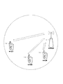
- FIG. 1 is a conceptual diagram of a wireless communication system in the present embodiment.
- the radio communication system includes terminal apparatuses 1A to 1C and a base station apparatus 3.
- the terminal devices 1A to 1C are also referred to as terminal devices 1.
- the following uplink physical channels are used in uplink wireless communication from the terminal device 1 to the base station device 3.
- the uplink physical channel is used to transmit information output from an upper layer.
- -PUCCH Physical Uplink Control Channel
- PUSCH Physical Uplink Shared Channel
- PRACH Physical Random Access Channel
- the PUCCH is used for transmitting uplink control information (Uplink Control Information: UCI).
- the uplink control information may include channel state information (CSI: Channel State Information) used to indicate the state of the downlink channel.
- the uplink control information may include a scheduling request (SR: “Scheduling” Request) used for requesting the UL-SCH resource.
- the uplink control information may include HARQ-ACK (Hybrid Automatic Repeat request ACKnowledgement).
- HARQ-ACK may indicate HARQ-ACK for downlink data (Transport block, Medium Access Control Protocol Data Unit: MAC-PDU, Downlink-Shared Channel: DL-SCH, Physical Downlink Shared Channel: PDSCH).
- HARQ-ACK may indicate ACK (acknowledgement) or NACK (negative-acknowledgement).
- HARQ-ACK is also referred to as ACK / NACK, HARQ feedback, HARQ response, HARQ information, or HARQ control information.
- the PUSCH is used to transmit uplink data (Uplink-Shared Channel: UL-SCH).
- the PUSCH may also be used to transmit HARQ-ACK and / or CSI along with uplink data.
- the PUSCH may be used to transmit only CSI, or only HARQ-ACK and CSI. That is, PUSCH may be used to transmit only uplink control information.
- the base station device 3 and the terminal device 1 exchange (transmit / receive) signals in a higher layer.
- the base station device 3 and the terminal device 1 transmit and receive RRC signaling (RRC message: Radio Resource Control message, RRC information: also called Radio Resource Control information) in a radio resource control (RRC: Radio Resource Control) layer. May be.
- RRC Radio Resource Control
- the base station device 3 and the terminal device 1 may transmit and receive a MAC control element in a MAC (Medium Access Control) layer.
- MAC Medium Access Control
- the RRC signaling and / or the MAC control element is also referred to as a higher layer signal.
- the PUSCH may be used to transmit RRC signaling and MAC control elements.
- the RRC signaling transmitted from the base station apparatus 3 may be common signaling for a plurality of terminal apparatuses 1 in the cell.
- the RRC signaling transmitted from the base station device 3 may be signaling dedicated to a certain terminal device 1 (also referred to as dedicated signaling). That is, user device specific (user device specific) information may be transmitted to a certain terminal device 1 using dedicated signaling.
- PRACH is used to transmit a random access preamble.
- PRACH may also be used to indicate initial connection establishment (initial ⁇ ⁇ ⁇ ⁇ ⁇ ⁇ ⁇ ⁇ connection establishment) procedures, handover procedures, connection re-establishment procedures, synchronization for uplink transmissions (timing adjustment), and PUSCH resource requirements. Good.
- the following uplink physical signals are used in uplink wireless communication.
- the uplink physical signal is not used for transmitting information output from the higher layer, but is used by the physical layer.
- UL RS Uplink Reference Signal
- DMRS Demodulation Reference Signal
- SRS Sounding Reference Signal
- DMRS is related to transmission of PUSCH or PUCCH.
- DMRS is time-multiplexed with PUSCH or PUCCH.
- the base station apparatus 3 uses DMRS to perform propagation channel correction for PUSCH or PUCCH.
- transmitting both PUSCH and DMRS is simply referred to as transmitting PUSCH.
- transmitting both PUCCH and DMRS is simply referred to as transmitting PUCCH.
- SRS is not related to PUSCH or PUCCH transmission.
- the base station apparatus 3 uses SRS to measure the uplink channel state.
- the following downlink physical channels are used in downlink radio communication from the base station apparatus 3 to the terminal apparatus 1.
- the downlink physical channel is used to transmit information output from an upper layer.
- PBCH Physical Broadcast Channel
- PCFICH Physical Control Format Indicator Channel
- PHICH Physical Hybrid automatic repeat request Indicator Channel
- PDCCH Physical Downlink Control Channel
- EPDCCH Enhanced Physical Downlink Control Channel
- PDSCH Physical Downlink Shared Channel
- PMCH Physical Multicast Channel
- the PBCH is used to broadcast a master information block (Master Information Block: MIB, Broadcast Channel: BCH) commonly used in the terminal device 1.
- MIB Master Information Block
- BCH Broadcast Channel
- PCFICH is used for transmitting information indicating a region (OFDM symbol) used for transmission of PDCCH.
- the PHICH is used to transmit an HARQ indicator (HARQ feedback, response information) indicating ACK (ACKnowledgement) or NACK (Negative ACKnowledgement) for uplink data (Uplink Shared Channel: UL-SCH) received by the base station apparatus 3. It is done.
- HARQ indicator HARQ feedback, response information
- ACK acknowledgement
- NACK Negative ACKnowledgement
- DCI Downlink Control Information
- a plurality of DCI formats are defined for transmission of downlink control information. That is, fields for downlink control information are defined in the DCI format and mapped to information bits.
- a DCI format (for example, DCI format 1A, DCI format 1C) used for scheduling one PDSCH (transmission of one downlink transport block) in one cell is defined as a DCI format for the downlink. May be.
- the DCI format for the downlink includes information related to PDSCH scheduling.
- the DCI format for the downlink includes downlink control information such as a carrier indicator field (CIF), information on resource block allocation, information on MCS (Modulation and Coding Scheme), and the like.
- the DCI format for the downlink is also called a downlink grant (downlink grant) or a downlink assignment (downlink assignment).
- DCI formats for example, DCI format 0, DCI format 4 used for scheduling one PUSCH (transmission of one uplink transport block) in one cell are used. Defined.
- the information on PUSCH scheduling is included in the DCI format for the uplink.
- the DCI format for the uplink includes a carrier indicator field (CIF), information on resource block assignment and / or hopping (Resource block assignment and and / or hopping resource allocation), MCS and / or redundancy sea version.
- This includes downlink control information such as information on (Modulation and coding scheme and / or redundancy and version) and information used to indicate the number of transmission layers (Precoding information and number number of layers).
- the DCI format for the uplink is also referred to as an uplink grant or an uplink assignment.
- the terminal device 1 may receive the downlink data using the scheduled PDSCH. Moreover, when the PUSCH resource is scheduled using the uplink grant, the terminal device 1 may transmit the uplink data and / or the uplink control information using the scheduled PUSCH.
- the terminal device 1 may monitor a set of PDCCH candidates (PDCCH candidates) and / or EPDCCH candidates (EPDCCH candidates).
- PDCCH may indicate PDCCH and / or EPDDCH. That is, in the present embodiment, PDCCH and EPDCCH are collectively referred to simply as PDCCH.
- a PDCCH candidate and an EPDCCH candidate are generically referred to simply as a PDCCH candidate.
- the PDCCH candidate indicates a candidate in which the PDCCH may be arranged and / or transmitted by the base station apparatus 3.
- the term “monitor” may include the meaning that the terminal apparatus 1 attempts to decode each PDCCH in the set of PDCCH candidates according to all the DCI formats to be monitored.
- a set of PDCCH candidates monitored by the terminal device 1 and / or a set of EPDCCH candidates monitored by the terminal device 1 are also referred to as a search space.
- the search space may include a common search space (CSS: Common Search Space).
- the CSS may be defined as a common space for the plurality of terminal devices 1.
- the search space may include a user device specific search space (USS: “UE-specific” Search “Space”).
- USS user device specific search space
- the USS may be given by at least a C-RNTI (Cell-Radio Network Temporary Identifier) assigned to the terminal device 1 (may be defined based on the C-RNTI).
- the USS may be given at least by the Temporary C-RNTI assigned to the terminal device 1 (may be defined based on the Temporary C-RNTI).
- the terminal device 1 may monitor the PDCCH and detect the PDCCH addressed to itself in the CSS and / or USS. Moreover, the terminal device 1 may monitor EPDCCH in CSS and / or USS, and may detect EPDCCH addressed to its own device.
- the RNTI assigned to the terminal device 1 by the base station device 3 is used for transmission of the downlink control information (transmission on the PDCCH).
- CRC Cyclic Redundancy check
- DCI may be downlink control information
- the CRC parity bits are scrambled by RNTI.
- the CRC parity bit added to the DCI format may be obtained from the payload of the corresponding DCI format.
- the terminal device 1 tries to decode the DCI format to which the CRC parity bit scrambled by the RNTI is added, and detects the DCI format in which the CRC is successful as the DCI format addressed to the own device (also known as blind decoding). Called). That is, the terminal device 1 may detect the PDCCH accompanied by the CRC scrambled by the RNTI. Further, the terminal device 1 may detect a PDCCH accompanied by a DCI format to which a CRC parity bit scrambled by RNTI is added.
- the RNTI may include a C-RNTI (Cell-Radio Network Temporary Identifier).
- the C-RNTI is a unique (unique) identifier for the terminal device 1 used for RRC connection and scheduling identification.
- C-RNTI may also be used for dynamically scheduled unicast transmissions.
- RNTI may include SPS C-RNTI (Semi-Persistent Scheduling C-RNTI).
- SPS C-RNTI Semi-Persistent Scheduling C-RNTI
- the SPS C-RNTI is a unique (unique) identifier for the terminal device 1 used for semi-persistent scheduling.
- SPS C-RNTI may also be used for semi-persistently scheduled unicast transmissions.
- Temporary C-RNTI may include Temporary C-RNTI.
- Temporary C-RNTI is a unique (unique) identifier for the preamble transmitted by the terminal device 1 used during the contention-based random access procedure.
- Temporary C-RNTI may also be used for dynamically scheduled transmissions.
- the PDSCH is used to transmit downlink data (Downlink Shared Channel: DL-SCH).
- the PDSCH is used for transmitting a system information message.
- the system information message may be cell specific (cell specific) information.
- System information is included in RRC signaling.
- the PDSCH is used to transmit RRC signaling and a MAC control element.
- PMCH is used to transmit multicast data (Multicast Channel: MCH).
- the following downlink physical signals are used in downlink wireless communication.
- the downlink physical signal is not used for transmitting information output from the upper layer, but is used by the physical layer.
- SS Synchronization signal
- DL RS Downlink Reference Signal
- the synchronization signal is used for the terminal device 1 to synchronize the downlink frequency domain and time domain.
- the synchronization signal is arranged in subframes 0, 1, 5, and 6 in the radio frame.
- the synchronization signal is arranged in subframes 0 and 5 in the radio frame.
- the downlink reference signal is used for the terminal device 1 to correct the propagation path of the downlink physical channel.
- the downlink reference signal is used for the terminal apparatus 1 to calculate downlink channel state information.
- the following five types of downlink reference signals are used.
- -CRS Cell-specific Reference Signal
- URS UE-specific Reference Signal
- PDSCH PDSCH
- DMRS Demodulation Reference Signal
- EPDCCH Non-Zero Power Chanel State Information-Reference Signal
- ZP CSI-RS Zero Power Chanel State Information-Reference Signal
- MBSFN RS Multimedia Broadcast and Multicast Service over Single Frequency Network Reference signal
- PRS Positioning Reference Signal
- the downlink physical channel and the downlink physical signal are collectively referred to as a downlink signal.
- the uplink physical channel and the uplink physical signal are collectively referred to as an uplink signal.
- the downlink physical channel and the uplink physical channel are collectively referred to as a physical channel.
- the downlink physical signal and the uplink physical signal are collectively referred to as a physical signal.
- BCH, MCH, UL-SCH and DL-SCH are transport channels.
- a channel used in a medium access control (Medium Access Control: MAC) layer is referred to as a transport channel.
- a transport channel unit used in the MAC layer is also referred to as a transport block (transport block: TB) or a MAC PDU (Protocol Data Unit).
- HARQ HybridbrAutomatic Repeat reQuest
- the transport block is a unit of data that the MAC layer delivers to the physical layer.
- the transport block is mapped to a code word, and an encoding process is performed for each code word.
- one or a plurality of serving cells may be set for the terminal device 1.
- a technique in which the terminal device 1 communicates via a plurality of serving cells is referred to as cell aggregation or carrier aggregation.
- the present embodiment may be applied to each of one or a plurality of serving cells set for the terminal device 1. Further, the present embodiment may be applied to a part of one or a plurality of serving cells set for the terminal device 1. Further, the present embodiment may be applied to each of one or a plurality of serving cell groups (for example, a PUCCH cell group or a timing advance group) set for the terminal device 1 described later. In addition, the present embodiment may be applied to a part of one or a plurality of serving cell groups set for the terminal device 1.
- serving cell groups for example, a PUCCH cell group or a timing advance group
- TDD Time Division Duplex
- FDD Frequency Division Duplex
- TDD or FDD may be applied to all of one or a plurality of serving cells.
- a serving cell to which TDD is applied and a serving cell to which FDD is applied may be aggregated.
- the frame structure corresponding to FDD is also referred to as “frame structure type 1”.
- the frame structure corresponding to TDD is also referred to as “frame structure type 2”.
- the set one or more serving cells include one primary cell and one or more secondary cells.
- the primary cell may be a serving cell that has undergone an initial connection establishment (initial connectionabestablishment) procedure, a serving cell that has initiated a connection re-establishment procedure, or a cell designated as a primary cell in a handover procedure.
- the secondary cell may be set at the time when the RRC connection is established or later.
- a carrier corresponding to a serving cell is referred to as a downlink component carrier.
- a carrier corresponding to a serving cell is referred to as an uplink component carrier.
- the downlink component carrier and the uplink component carrier are collectively referred to as a component carrier.
- the terminal device 1 may perform transmission and / or reception on a plurality of physical channels simultaneously in one or a plurality of serving cells (component carriers).
- one physical channel may be transmitted in one serving cell (component carrier) among a plurality of serving cells (component carriers).
- the primary cell is used for transmission of PUCCH. Also, the primary cell is not deactivated (primary cell cannot be deactivated). Cross-carrier scheduling is not applied to primary (Cross-carrier scheduling does not apply to primary cell). That is, the primary cell is always scheduled using the PDCCH in the primary cell (primary cell is always scheduled via its PDCCH).
- the cross carrier scheduling may not be applied to the certain secondary cell (In a case that PDCCH (PDCCH monitoring) of a secondary cell is configured, cross-carries scheduling may not apply this secondary cell). That is, in this case, the secondary cell may always be scheduled using the PDCCH in the secondary cell. Further, when PDCCH (which may be monitored by PDCCH) is not set in a certain secondary cell, cross-carrier scheduling is applied, and the secondary cell is always PDCCH in one other serving cell (one other serving cell). May be scheduled.
- the secondary cell used for transmission of PUCCH is called a PUCCH secondary cell and a special secondary cell.
- secondary cells that are not used for PUCCH transmission are referred to as non-PUCCH secondary cells, non-special secondary cells, non-PUCCH serving cells, and non-PUCCH cells.
- the primary cell and the PUCCH secondary cell are collectively referred to as a PUCCH serving cell and a PUCCH cell.
- the PUCCH serving cell (primary cell, PUCCH secondary cell) always has a downlink component carrier and an uplink component carrier. Also, PUCCH resources are set in the PUCCH serving cell (primary cell, PUCCH secondary cell).
- non-PUCCH serving cell may have only downlink component carriers.
- a non-PUCCH serving cell may have a downlink component carrier and an uplink component carrier.
- the terminal device 1 may perform transmission on the PUCCH in the PUCCH serving cell. That is, the terminal device 1 may perform transmission on the PUCCH in the primary cell. Moreover, the terminal device 1 may perform transmission by PUCCH in a PUCCH secondary cell. That is, the terminal device 1 does not perform transmission on the PUCCH in the non-special secondary cell.
- the PUCCH secondary cell may be defined as a primary cell and a serving cell that is not a secondary cell.
- the base station apparatus 3 may set one or a plurality of serving cells using a higher layer signal.
- one or more secondary cells may be configured to form a set of multiple serving cells with the primary cell.
- the serving cell set by the base station device 3 may include a PUCCH secondary cell.
- the PUCCH secondary cell may be set by the base station device 3.
- the base station apparatus 3 may transmit an upper layer signal including information (index) used for setting a PUCCH secondary cell.
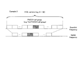
- 2A to 2C are diagrams for explaining the cell group in the present embodiment.
- 2A to 2C show three examples (Example 1, Example 2, and Example 3) as examples of setting (configuration, definition) of the PUCCH cell group.
- a group of one or more serving cells is referred to as a PUCCH cell group.
- the PUCCH cell group may be a group related to transmission on PUCCH (transmission of uplink control information on PUCCH).
- a certain serving cell belongs to any one PUCCH cell group.
- the PUCCH cell group may be set differently from the example shown in FIGS. 2A to 2C.
- the PUCCH cell group may be set by the base station apparatus 3.
- the base station apparatus 3 may transmit an upper layer signal including information (which may be an index or a cell group index) used for setting a PUCCH cell group.
- the present embodiment is applicable to a group of one or a plurality of serving cells different from the PUCCH cell group described above.
- the base station apparatus 3 may set one or a plurality of serving cell groups in association with the serving cell indicated using the carrier indicator field (CIF).
- the base station device 3 may set a timing advance group including one or a plurality of serving cells.
- the base station apparatus 3 may set one or a plurality of serving cell groups in association with uplink transmission. Further, the base station apparatus 3 may set one or a plurality of serving cell groups in association with downlink transmission.
- a group of one or a plurality of serving cells set by the base station apparatus 3 is also referred to as a cell group. That is, the PUCCH cell group may be included in the cell group. Further, the timing advance group may be included in the cell group.
- the base station apparatus 3 and / or the terminal apparatus 1 may execute the operations described in the present embodiment for each cell group. That is, the base station device 3 and / or the terminal device 1 may execute the operation described in this embodiment in one cell group.
- the base station device 3 and / or the terminal device 1 may support carrier aggregation of up to 32 downlink component carriers (downlink cells, up to 32 downlink component carriers). That is, the base station device 3 and / or the terminal device 1 can simultaneously perform transmission and / or reception on a plurality of physical channels in up to 32 serving cells. That is, the base station apparatus 3 may set up to 32 serving cells for the terminal apparatus 1.
- the number of uplink component carriers may be smaller than the number of downlink component carriers.
- the base station device 3 and / or the terminal device 1 may support carrier aggregation of up to 5 downlink component carriers (up to 5 downlink component carriers). That is, the base station device 3 and / or the terminal device 1 can simultaneously perform transmission and / or reception on a plurality of physical channels in up to five serving cells. That is, the base station apparatus 3 may set up to 5 serving cells for the terminal apparatus 1.
- the number of uplink component carriers may be smaller than the number of downlink component carriers.
- FIG. 2A shows that a first cell group and a second cell group are set as cell groups (here, PUCCH cell groups).
- the base station apparatus 3 may transmit a downlink signal in the first cell group.
- the terminal device 3 may transmit an uplink signal in the first cell group (may transmit uplink control information on the PUCCH in the first cell group).
- the base station device 3 and the terminal device 1 correspond to the 20 downlink component carriers.
- Uplink control information may be transmitted and received.
- the terminal device 1 may transmit HARQ-ACK (HARQ-ACK for transmission on PDSCH, HARQ-ACK for transport block) corresponding to 20 downlink component carriers. Moreover, the terminal device 1 may transmit CSI corresponding to 20 downlink component carriers. Moreover, the terminal device 1 may transmit SR for every cell group. Similarly, the base station apparatus 3 and the terminal apparatus 1 may transmit / receive uplink control information in the second cell group.
- HARQ-ACK HARQ-ACK for transmission on PDSCH, HARQ-ACK for transport block
- the base station device 3 and the terminal device 1 may set a cell group as shown in FIG. 2B and transmit / receive uplink control information.
- the base station apparatus 3 and the terminal device 1 may set a cell group as shown in FIG. 2C, and may transmit / receive uplink control information.
- one cell group may include at least one serving cell (for example, PUCCH serving cell).
- one cell group may include only one serving cell (for example, only PUCCH serving cell).
- one PUCCH cell group may include one PUCCH serving cell and one or more non-PUCCH serving cells.
- a cell group including a primary cell is referred to as a primary cell group.
- a cell group that does not include a primary cell is referred to as a secondary cell group.
- the PUCCH cell group including the primary cell is referred to as a primary PUCCH cell group.
- a PUCCH cell group that does not include a primary cell is referred to as a secondary PUCCH cell group.
- the secondary PUCCH cell group may include a PUCCH secondary cell.
- the index for the primary PUCCH cell group may always be defined as 0.
- the index with respect to a secondary PUCCH cell group may be set by the base station apparatus 3 (a network apparatus may be sufficient).
- the base station apparatus 3 may transmit the information used for indicating the PUCCH secondary cell by including it in the higher layer signal and / or PDCCH (downlink control information transmitted on the PDCCH). Good.
- the terminal device 1 may determine the PUCCH secondary cell based on information used to indicate the PUCCH secondary cell.
- the cell index of the PUCCH secondary cell may be defined in advance by a specification or the like.
- the PUCCH in the PUCCH serving cell includes uplink control information (HARQ-ACK, CSI (eg, periodic CSI)) for the serving cell (PUCCH serving cell, non-PUCCH serving cell) included in the PUCCH cell group to which the PUCCH serving cell belongs. And / or SR) may be used.
- HARQ-ACK uplink control information
- CSI eg, periodic CSI
- uplink control information (HARQ-ACK, CSI (eg, periodic CSI) and / or SR) for the serving cell (PUCCH serving cell, non-PUCCH serving cell) included in the PUCCH cell group is included in the PUCCH cell group. Transmitted using the PUCCH in the serving PUCCH serving cell.
- the present embodiment may be applied only to the transmission of HARQ-ACK. Further, the present embodiment may be applied only to transmission of CSI (for example, periodic CSI). Further, the present embodiment may be applied only to SR transmission. Further, the present embodiment may be applied to HARQ-ACK transmission, CSI (for example, periodic CSI) transmission, and / or SR transmission.
- CSI for example, periodic CSI
- a cell group (may be a PUCCH cell group) for transmission of HARQ-ACK may be set.
- a cell group (may be a PUCCH cell group) for transmission of CSI (for example, periodic CSI) may be set.
- CSI for example, periodic CSI
- a cell group (may be a PUCCH cell group) for SR transmission may be set.
- a cell group for HARQ-ACK transmission, a cell group for CSI (for example, periodic CSI) transmission, and / or a cell group for SR transmission may be individually set.
- a common cell group may be set as a cell group for HARQ-ACK transmission, a cell group for CSI (for example, periodic CSI) transmission, and / or a cell group for SR transmission.
- the number of cell groups for HARQ-ACK transmission may be one or two.
- the number of cell groups for CSI transmission may be one or two.
- the number of cell groups for transmission of SR may be one or two.
- the cell group for transmission of CSI (for example, periodic CSI) and / or the cell group for transmission of SR may not be set (defined).
- MTA Multiple Timing Advance
- the base station apparatus 3 may set a plurality of timing advance groups for the terminal apparatus 1 that supports MTA.
- the timing advance group may include one or more serving cells.
- the timing advance group including the primary cell is referred to as a primary timing advance group.
- a timing advance group that does not include a primary cell is referred to as a secondary timing advance group.
- the secondary timing advance group may include only one or a plurality of secondary cells.
- the PUCCH secondary cell may be included in either the primary timing advance group or the secondary timing advance group.
- the terminal device 1 may individually control the uplink transmission timing in the primary timing advance group and the uplink transmission timing in the secondary timing advance group. For example, the terminal device 1 uses the uplink transmission timing for PUCCH, PUSCH, and / or SRS in the primary timing advance group, and the uplink transmission for PUCCH, PUSCH, and / or SRS in the secondary timing advance group. Timing may be individually controlled.
- the uplink transmission timing may be an uplink transmission timing for PUCCH, PUSCH, and / or SRS.
- the uplink transmission timing in the secondary cell belonging to the primary timing advance group may be the same as the uplink transmission timing in the primary cell. That is, when the terminal device 1 receives the timing advance command for the primary cell from the base station device 3, the terminal device 1 refers to the timing advance command for the primary cell, and thereby the uplink in the secondary cell belonging to the primary cell and / or the primary timing advance group.
- the link transmission timing may be adjusted.
- the terminal device 1 when the terminal device 1 receives a timing advance command for the secondary timing advance group from the base station device 3, the terminal device 1 refers to the timing advance command for the secondary timing advance group, so that the secondary cells belonging to the secondary timing advance group (all The uplink transmission timing in the secondary cell may be adjusted.
- the uplink transmission timing may be the same for all secondary cells belonging to the secondary timing advance group.
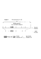
- FIG. 3 is a diagram showing a configuration of slots in the present embodiment.
- the horizontal axis represents the time axis
- the vertical axis represents the frequency axis.
- normal CP normal Cyclic Prefix
- extended CP extended Cyclic Prefix
- a physical signal or physical channel transmitted in each slot is represented by a resource grid.
- the resource grid may be defined by a plurality of subcarriers and a plurality of OFDM symbols.
- a resource grid may be defined by a plurality of subcarriers and a plurality of SC-FDMA symbols.
- the number of subcarriers constituting one slot may depend on the cell bandwidth.
- the number of OFDM symbols or SC-FDMA symbols constituting one slot may be seven.
- each of the elements in the resource grid is referred to as a resource element.
- the resource element may be identified using a subcarrier number and an OFDM symbol or SC-FDMA symbol number.
- the resource block may be used to express a mapping of a certain physical channel (such as PDSCH or PUSCH) to a resource element.
- virtual resource blocks and physical resource blocks may be defined as resource blocks.
- a physical channel may first be mapped to a virtual resource block. Thereafter, the virtual resource block may be mapped to a physical resource block.
- One physical resource block may be defined from 7 consecutive OFDM symbols or SC-FDMA symbols in the time domain and 12 consecutive subcarriers in the frequency domain. Therefore, one physical resource block may be composed of (7 ⁇ 12) resource elements.
- One physical resource block may correspond to one slot in the time domain and 180 kHz in the frequency domain.
- physical resource blocks may be numbered from 0 in the frequency domain.
- CRC parity bits added to the DCI format (DCI: may be downlink control information) will be described in detail.
- CRC parity bit “CRC bit”, and “CRC” may be the same.
- the number of CRC parity bits added to the corresponding DCI format may be 24 or 16. That is, the base station apparatus 3 and the terminal apparatus 1 select whether the number of CRC parity bits added to the corresponding DCI format is 24 or 16 according to one or more conditions ( Determination, judgment). That is, the base station apparatus 3 uses the DCI to which the first CRC parity bit (for example, the CRC parity bit having 24 numbers) or the second CRC parity bit (for example, the CRC parity bit having 16 numbers) is added.
- a format may be sent.
- the terminal device 1 may monitor the DCI format to which the first CRC parity bit or the second CRC parity bit is added.
- the DCI format may be transmitted on the PDCCH.
- the base station apparatus 3 uses higher layer parameters (for example, RRC layer parameters) used for the terminal apparatus 1 to set (may be instructed or defined) to monitor a PDCCH including 24-bit CRC parity bits. May be sent. Also, the base station apparatus 3 sets (may be instructed or defined) in the terminal apparatus 1 whether to monitor a PDCCH including a CRC parity bit of 24 bits or to monitor a PDCCH including a CRC parity bit of 16 bits.
- the higher layer parameters used for this purpose may be transmitted.
- the “upper layer parameter”, “upper layer message”, “upper layer signal”, “upper layer information”, and “upper layer information element” are the same. It may be.
- the base station apparatus 3 may transmit information (parameters) related to DCI monitoring to which the first CRC parity bit is added to the terminal apparatus 1. Further, the base station apparatus 3 may transmit information (parameters) related to DCI monitoring to which the second CRC parity bit is added to the terminal apparatus 1.
- the information (parameter) related to the DCI monitor to which the first CRC parity bit is added and / or the information (parameter) related to the DCI monitor to which the second CRC parity bit is added are simply monitored by the DCI. Also described as a parameter.
- “PDCCH that transmits a DCI format with a CRC parity bit added”, “PDCCH that includes a CRC parity bit and includes a DCI format”, “PDCCH that includes a CRC parity bit”, and , “PDCCH including DCI format” may be the same.
- “PDCCH including X” and “PDCCH with X” may be the same. That is, the terminal device 1 may monitor the DCI format. The terminal device 1 may monitor DCI. Moreover, the terminal device 1 may monitor PDCCH.
- parameters related to DCI monitoring may be set for each serving cell.
- parameters related to DCI monitoring may be set for each cell group.
- the parameter regarding the monitor of DCI may be set only with respect to a secondary cell.
- the parameters related to DCI monitoring may be set only for a group of serving cells that do not include a primary cell.
- the PDCCH (DCI, DCI in the first serving cell is set. May be monitored) based on DCI monitoring parameters.
- the PDCCH (which may be DCI or DCI format) in the first serving cell may be used for scheduling of the PDSCH in the first serving cell and / or the second serving cell.
- the PDCCH (which may be DCI or DCI format) in the first serving cell may be used for PUSCH scheduling in the first serving cell and / or the second serving cell.
- the base station apparatus 3 transmits a higher layer parameter (for example, an RRC layer parameter) used to instruct that the PDSCH and / or PUSCH is scheduled using the PDCCH in any serving. May be. That is, the base station apparatus 3 may transmit information used to instruct in which serving cell a downlink assignment (also referred to as downlink allocation) is signaled. Moreover, the base station apparatus 3 may transmit the information used for instruct
- a downlink assignment also referred to as downlink allocation
- the parameters related to DCI monitoring may be applied only to USS. That is, the parameters related to the DCI monitor may not be applied to the DCI monitor in the CSS, but may be applied only to the DCI monitor in the USS. Also, the parameters related to DCI monitoring may be applied to only one of PDCCH and EPDCCH.
- the terminal device 1 may monitor the PDCCH including 24-bit CRC parity bits. That is, the terminal device 1 is related to an upper layer parameter (which may be set based on a parameter related to DCI monitoring or a parameter related to DCI monitoring) instructing the terminal device 1 to monitor a PDCCH including 24 CRC parity bits. If the predetermined condition is satisfied, the PDCCH including 24 CRC CRC bits may be monitored.
- the terminal device 1 may monitor the PDCCH including 24-bit CRC parity bits in the secondary cell. Further, when a predetermined condition is satisfied, the terminal device 1 may monitor a PDCCH including 24-bit CRC parity bits in a secondary cell belonging to a serving cell group that does not include a primary cell. Moreover, the terminal device 1 may monitor PDCCH including a CRC parity bit of 24 bits in USS (only USS may be used) when a predetermined condition is satisfied. Moreover, the terminal device 1 may monitor EPDCCH (only EPDCCH) including a 24-bit CRC parity bit when a predetermined condition is satisfied.
- the terminal device 1 when the terminal device 1 is configured with a larger number of serving cells (for example, more than 5 serving cells) using higher layer parameters (for example, RRC layer parameters), the terminal device 1 May monitor PDCCH including 24-bit CRC parity bits (may be determined to be monitored). That is, when the terminal apparatus 1 is configured with a predetermined number or less of serving cells (for example, 5 or less serving cells) using higher-layer parameters (for example, RRC layer parameters), the terminal apparatus 1
- the PDCCH including the CRC parity bits of 24 bits or the PDCCH including the CRC parity bits of 16 bits may be monitored based on the setting based on the parameters regarding the monitoring of the above.
- the number of PDCCH candidates monitored by the terminal device 1 in a certain subframe and / or the size of the DCI format monitored by the terminal device 1 in the certain subframe (the payload size of the DCI format, the payload size of the DCI format)
- the terminal device 1 may monitor the PDCCH including the CRC parity bits of 24 bits (may be determined to be monitored).
- the terminal device 1 may monitor the PDCCH including 24-bit CRC parity bits (may be determined to be monitored).
- the terminal apparatus 1 is instructed to monitor the PDCCH including the CRC parity bits of 24 bits (for example, the RRC layer parameter) and / or the terminal based on the predetermined condition as described above.
- the device 1 monitors the PDCCH including the CRC parity bits of 24 bits is simply described as “the terminal device 1 is set to monitor the PDCCH including the CRC parity bits of 24 bits”.
- the terminal apparatus 1 is instructed to monitor the PDCCH including the CRC parity bits of 24 bits (for example, the RRC layer parameter) and / or the terminal based on the predetermined condition as described above.
- the device 1 does not monitor PDCCH including 24-bit CRC parity bits is also described as “the terminal device 1 is not set to monitor PDCCH including 24-bit CRC parity bits”.
- the number of CRC parity bits added to the corresponding DCI format may be 16. That is, when at least one of the following conditions (a) to (d) is satisfied, the base station apparatus 3 may transmit DCI to which 16 CRC parity bits are added. Further, when at least one of the following conditions (a) to (d) is satisfied, the terminal device 1 may monitor DCI to which 16 CRC parity bits are added. That is, when at least one of the following conditions (a) to (d) is satisfied, the terminal device 1 may monitor the PDCCH including 16 CRC parity bits.
- the terminal device 1 when the terminal device 1 is not set using upper layer parameters (which may be RRC layer parameters or DCI monitoring parameters) to monitor a PDCCH including 24-bit CRC parity bits,
- the number of CRC parity bits added to the corresponding DCI format may be 16.
- the number of CRC parity bits added to the corresponding DCI format may be 16. That is, when transmitting the DCI format in CSS, the base station apparatus 3 may transmit the DCI format with a 16-bit CRC parity bit added. Further, when receiving the DCI format in CSS, the terminal device 1 may receive the DCI format to which a 16-bit CRC parity bit is added.
- the number of CRC parity bits added to the corresponding DCI format may be 16 or 24.
- the base station apparatus 3 when the base station apparatus 3 is set for the terminal apparatus 1 to monitor PDCCH (which may be a DCI format) including 24-bit CRC parity bits and transmits the DCI format in USS,
- the DCI format may be transmitted with a 24-bit CRC parity bit added.
- the terminal device 1 is configured to monitor a PDCCH (which may be a DCI format) including a CRC parity bit of 24 bits, and when the DCI format is received in the USS, the terminal device 1 has a 24-bit CRC. You may receive the DCI format to which the parity bit was added.
- the base station apparatus 3 is not set for the terminal apparatus 1 to monitor the PDCCH (which may be a DCI format) including 24-bit CRC parity bits, and the DCI format is transmitted in the USS. Alternatively, 16-bit CRC parity bits may be added to the DCI format for transmission. Further, the terminal device 1 is not set to monitor the PDCCH (which may be in the DCI format) including the CRC parity bits of 24 bits, and when the terminal device 1 receives the DCI format in the USS, 24 A DCI format to which a CRC parity bit of bits is added may be received.
- the PDCCH which may be a DCI format
- 24 16-bit CRC parity bits
- the number of CRC parity bits added to the corresponding DCI format may be 16. That is, when transmitting the DCI format at least in the USS given by the Temporary C-RNTI, the base station apparatus 3 may transmit the DCI format with a 16-bit CRC parity bit added. Further, when the terminal device 1 receives the DCI format at least in the USS given by the Temporary C-RNTI, the terminal device 1 may receive the DCI format to which 16 CRC parity bits are added.
- the number of CRC parity bits added to the corresponding DCI format may be 16 or 24.
- the base station apparatus 3 sets the terminal apparatus 1 to monitor a PDCCH (which may be a DCI format) including 24 CRC parity bits, and gives the DCI format at least by C-RNTI.
- a CRC parity bit of 24 bits may be added to the DCI format for transmission.
- the terminal device 1 is set so that the terminal device 1 monitors a PDCCH (which may be a DCI format) including 24 CRC parity bits, and receives the DCI format at least in the USS provided by the C-RNTI. In this case, a DCI format to which 24-bit CRC parity bits are added may be received.
- the base station apparatus 3 when the base station apparatus 3 is set for the terminal apparatus 1 to monitor a PDCCH (which may be in a DCI format) including 24-bit CRC parity bits, at least a 24-bit USS given by the C-RNTI is used.
- the DCI to which the CRC parity bit is added may be transmitted, and the DCI to which the CRC parity bit of 16 bits is added in the CSS may be transmitted.
- the base station apparatus 3 when the base station apparatus 3 is not set for the terminal apparatus 1 to monitor the PDCCH (which may be in the DCI format) including 24 CRC parity bits, at least 16 in the USS given by the C-RNTI.
- the DCI to which the CRC parity bit of the bit is added may be transmitted, and the DCI to which the CRC parity bit of 16 bits is added in the CSS may be transmitted.
- the terminal device 1 when the terminal device 1 is set to monitor a PDCCH (which may be in a DCI format) including a 24-bit CRC parity bit, at least a 24-bit CRC parity bit is added in the USS given by the C-RNTI.
- the DCI may be monitored, and the DCI to which a CRC parity bit of 16 bits is added in the CSS may be monitored.
- the terminal device 1 when the terminal device 1 is not set to monitor a PDCCH (which may be a DCI format) including 24-bit CRC parity bits, at least a 16-bit CRC parity bit is added in the USS given by the C-RNTI. It is also possible to monitor the DCI added with 16 CRC parity bits in the CSS.
- a PDCCH which may be a DCI format
- the terminal device 1 when the terminal device 1 is not set to monitor a PDCCH (which may be a DCI format) including 24-bit CRC parity bits, at least a 16-bit CRC parity bit is added in the USS given by the C-RNTI. It is also possible to monitor the DCI added with 16 CRC parity bits in the CSS.
- the base station apparatus 3 is provided by at least Temporary C-RNTI regardless of whether or not the terminal apparatus 1 is set to monitor a PDCCH (which may be a DCI format) including 24-bit CRC parity bits.
- a PDCCH which may be a DCI format
- CRC parity bits In USS, DCI to which a CRC parity bit of 16 bits is added may be transmitted.
- a PDCCH which may be a DCI format
- a PDCCH which may be a DCI format
- 24 CRC parity bits at least a 16-bit CRC in the USS given by the Temporary C-RNTI You may monitor DCI to which the parity bit was added.
- the number of CRC parity bits added to the corresponding DCI format may be 16.
- the predetermined RNTI may not include the C-RNTI.
- the predetermined RNTI may not include the SPS C-RNTI.
- the predetermined RNTI may include a Temporary C-RNTI.
- the predetermined RNTI may include RA-RNTI (Random Access Radio Network Temporary Identifier).
- the base station apparatus 3 is scrambled by the RA-RNTI regardless of whether or not the terminal apparatus 1 is set to monitor a PDCCH (which may be a DCI format) including 24 CRC parity bits. DCI to which a CRC parity bit of bits is added may be transmitted.
- a PDCCH which may be a DCI format
- the terminal device 1 has a 16-bit CRC parity bit scrambled by the RA-RNTI regardless of whether it is set to monitor a PDCCH (which may be a DCI format) including a 24-bit CRC parity bit.
- the added DCI may be monitored.
- the DCI to which the CRC parity bit scrambled by the RA-RNTI is added may be transmitted only in the CSS. That is, the DCI scrambled by the RA-RNTI and added with 16 CRC parity bits may be transmitted only in the CSS.
- the 24-bit CRC parity bits may be scrambled by C-RNTI. Further, the 16-bit CRC parity bits may be scrambled by C-RNTI or Temporary C-RNTI.
- the number of CRC parity bits added to the corresponding DCI format may be 24.
- the terminal apparatus 1 is set using a higher layer parameter (for example, an RRC layer parameter) to monitor a PDCCH including 24 CRC parity bits, and (2) the corresponding DCI The format is mapped to at least the USS given by C-RNTI, and (3) CRC parity bits added to the corresponding DCI format are scrambled by a RNTI other than a given RNTI (eg, C-RNTI) 24, the number of CRC parity bits added to the corresponding DCI format may be 24.
- a higher layer parameter for example, an RRC layer parameter
- the process in which the CRC parity bit is scrambled by the RNTI may be executed by the base station apparatus 3. That is, when performing the CRC parity check, the terminal device 1 may consider that the CRC parity bit is scrambled by the RNTI.
- error detection may be provided based on a bit sequence provided by CRC CRC bits being scrambled by RNTI. Also, error detection may be performed based on a bit sequence given by scrambling CRC parity bits with RNTI.
- the “16 CRC parity bits” is also referred to as “16-bit CRC”, “16-bit CRC”, or “16-bit CRC parity bit”.
- “a CRC parity bit of 24 numbers” is also referred to as “24-bit CRC”, “24-bit CRC”, or “24-bit CRC parity bit”.
- FIG. 4 is a diagram for explaining the addition of CRC parity bits in the present embodiment.
- the CRC parity bit may be added to the DCI format (DCI: may be downlink control information).
- the CRC parity bit may be scrambled by RNTI after being added to the DCI format.
- a i may be a DCI bit (DCI payload) corresponding to a CRC parity bit. Further, A may be the number of DCI bits (DCI payload size) corresponding to CRC parity bits. P i is a CRC parity bit. L may be the number of CRC parity bits.
- the bit sequence ⁇ b 0, ..., b B -1> is, DCI (DCI payload) ⁇ a 0 ,...,a A-1> the CRC parity bits ⁇ p 0, ..., is p L-1> It may be given by being added.
- FIGS. 5 to 8 the symbols are used in the same meaning.
- FIG. 5 is a diagram for explaining scrambling of CRC parity bits by RNTI in the present embodiment.
- RNTI ⁇ x rnti, 0, ..., x rnti, 15> may be provided by being scrambled by.
- RNTI ⁇ x rnti, 0 , ..., by being scrambled by x RNTI, 15> the bit sequence ⁇ c 0, ..., c A + L-1> is given, may be transmitted and received PDCCH.
- bit sequence ⁇ b 0, ..., b A -1, b A, ..., b A + 15> the payload of the DCI ⁇ a 0 ,...,a A-1> in 16-bit CRC ⁇ p 0, ..., It may be given by appending p L-1 >. That is, the bit sequence ⁇ b 0 ,..., B A-1 > may be DCI (DCI payload), and the bit sequence ⁇ b A ,..., B A + 15 > may be a 16-bit CRC. That is, the 16-bit CRC ⁇ b A ,..., B A + 15 > may be scrambled by RNTI ⁇ x rnti, 0 , ..., x rnti, 15 >.
- FIG. 6 is another diagram for explaining the scrambling of CRC parity bits by the RNTI in this embodiment.
- bit sequence ⁇ b 0, ..., b A -1, b A, ..., b A + 23> the payload of the DCI ⁇ a 0 ,...,a A-1> 24-bit CRC ⁇ p 0, ..., It may be given by appending p L-1 >. That is, the bit sequence ⁇ b 0 ,..., B A-1 > may be DCI (DCI payload), and the bit sequence ⁇ b A ,..., B A + 23 > may be a 24-bit CRC.
- bit sequence ⁇ b A + 8 ,..., B A + 23 > of the 24-bit CRC ⁇ b A ,..., B A + 23 > may be scrambled by RNTI ⁇ x rnti, 0 , ..., x rnti, 15 >.
- bit sequence ⁇ b A ,..., B A + 7 > in the 24-bit CRC ⁇ b A ,..., B A + 23 > may not be scrambled by RNTI ⁇ x rnti, 0 , ..., x rnti, 15 >.
- FIG. 7 is another diagram for explaining the scrambling of CRC parity bits by the RNTI in this embodiment.
- bit sequence ⁇ b 0, ..., b A -1, b A, ..., b A + 23> the payload of the DCI ⁇ a 0 ,...,a A-1> 24-bit CRC ⁇ p 0, ..., It may be given by appending p L-1 >. That is, the bit sequence ⁇ b 0 ,..., B A-1 > may be DCI (DCI payload), and the bit sequence ⁇ b A ,..., B A + 23 > may be a 24-bit CRC.
- bit sequence ⁇ b A + 8 ,..., B A + 23 > of the 24-bit CRC ⁇ b A ,..., B A + 23 > may be scrambled by RNTI ⁇ x rnti, 0 , ..., x rnti, 15 >. .
- 24-bit CRC ⁇ b A, ..., b A + 23> bit sequence of the ⁇ b A, ..., b A + 7> is, RNTI ⁇ x rnti, 0, ..., x rnti, 15> bit sequence of the ⁇ may be scrambled by x rnti, 8 ,..., x rnti, 15 >.
- 24-bit CRC ⁇ b A, ..., b A + 23> bit sequence of the ⁇ b A, ..., b A + 7> is, RNTI ⁇ x rnti, 0, ..., x rnti, 15> part of the ⁇ may be scrambled by x rnti, 8 ,..., x rnti, 15 >.
- FIG. 8 is another diagram for explaining the scrambling of CRC parity bits by the RNTI in this embodiment.
- bit sequence ⁇ b 0, ..., b A -1, b A, ..., b A + 23> the payload of the DCI ⁇ a 0 ,...,a A-1> 24-bit CRC ⁇ p 0, ..., It may be given by appending p L-1 >. That is, the bit sequence ⁇ b 0 ,..., B A-1 > may be DCI (DCI payload), and the bit sequence ⁇ b A ,..., B A + 23 > may be a 24-bit CRC.
- bit sequence ⁇ b A + 8 ,..., B A + 23 > of the 24-bit CRC ⁇ b A ,..., B A + 23 > may be scrambled by RNTI ⁇ x rnti, 0 , ..., x rnti, 15 >. .
- bit sequence ⁇ b A ,..., B A + 7 > in the 24-bit CRC ⁇ b A ,..., B A + 23 > is the bit sequence ⁇ RNTI ⁇ x rnti, 0 ,..., X rnti, 15 > ⁇ x rnti, 8, ..., x rnti, 15>, and, RNTI ⁇ x rnti, 0, ..., x rnti, 15 bit sequence ⁇ x RNTI, 0 of>, ..., are scrambled by x RNTI, 7> May be.
- 24-bit CRC ⁇ b A, ..., b A + 23> bit sequence of the ⁇ b A, ..., b A + 7> is, RNTI ⁇ x rnti, 0, ..., x rnti, 15> part of the ⁇ x rnti, 8 , ..., x rnti, 15 > and scrambled by the remaining ⁇ x rnti, 0 , ..., x rnti, 7 > of RNTI ⁇ x rnti, 0 , ..., x rnti, 15 > Also good.
- the terminal device 1 transmits the PDCCH including the CRC parity bits scrambled by the RNTI for the other terminal device 1 to the terminal device 1.
- the probability of erroneously determining that the PDCCH includes CRC parity bits that are scrambled by RNTI can be reduced.
- the base station apparatus 3 and the terminal apparatus 1 are switched by switching the number of CRC parity bits added to the corresponding DCI format (DCI: may be downlink control information) according to a predetermined condition. It becomes possible to communicate efficiently.
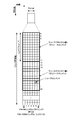
- FIG. 9 is a diagram for explaining downlink control information to which CRC parity bits are added in the present embodiment.
- the downlink control information shown in the upper part of FIG. 9 indicates downlink control information to which a 24-bit CRC is added. Also, the downlink control information shown in the lower part of FIG. 9 indicates downlink control information to which a 16-bit CRC is added.
- a bit sequence ⁇ b 0 ,..., B A-1 > indicates DCI (downlink control information) for the first terminal apparatus 1. Further, the bit sequence ⁇ b A ,..., B A + 23 > indicates a 24-bit CRC. Further, the bit sequence ⁇ x rnti, 0 ,..., X rnti, 15 > indicates the RNTI assigned to the first terminal apparatus 1.
- bit sequence ⁇ b ′ 0 ′ ,..., B ′ A′ ⁇ 1 > indicates downlink control information for the second terminal apparatus 1.
- bit sequence ⁇ b ′ A ′ ,..., B ′ A ′ + 15 > indicates a 16-bit CRC.
- bit sequence ⁇ x ′ rnti, 0 ,..., X ′ rnti, 15 > indicates the RNTI assigned to the second terminal apparatus 1.
- 24-bit CRC ⁇ b A, ..., b A + 23> bit sequence of the ⁇ b A, ..., b A + 15> is, RNTI ⁇ x rnti, 0, ..., x rnti, 15> be scrambled by Good.
- 24-bit CRC ⁇ b A, ..., b A + 23> bit sequence of the ⁇ b A + 16, ..., b A + 23> is, RNTI ⁇ x rnti, 0, ..., x rnti, 15> part of the ⁇ x rnti, 8 ,..., x rnti, 15 > and scrambled by the remaining ⁇ x rnti, 0 , ..., x rnti, 7 > of RNTI ⁇ x rnti, 0 , ..., x rnti, 15 > Also good.
- 16-bit CRC ⁇ b 'A', ... , b 'A' + 15> is, RNTI ⁇ x 'rnti, 0 , ..., x' rnti, 15> may be scrambled by.
- the latter 16 bits of the 24-bit CRC for the first terminal device 1 ⁇ b Scrambling applied to A + 8 ,..., B A + 23 > is applied to 16-bit CRC ⁇ b ′ A ′ ,..., B ′ A ′ + 15 > for the second terminal device 1 It may be the same. In this case, the probability that the second terminal apparatus 1 detects the PDCCH addressed to the first terminal apparatus 1 as the PDCCH of the second terminal apparatus 1 increases.
- RNTI ⁇ 1,1,1,1,1,1,1,1,1,1,1,1,1,1,1> is assigned to the first terminal device 1 and the second When RNTI ⁇ 1,1,1,1,1,1,1,1,0,0,0,0,0,0,0,0,0,0> is assigned to the terminal device 1 of
- the latter 16 bits of the 24-bit CRC for the terminal device 1 and the 16-bit CRC for the second terminal device 1 both have a bit sequence ⁇ 1,1,1,1,1,1,1. 0,0,0,0,0,0,0,0,0>.
- the base station apparatus 3 performs scrambling applied to the second half 16 bits ⁇ b A + 8 ,..., B A + 23 > of the 24-bit CRC for the first terminal apparatus 1. For each of the first terminal apparatus 1 and the second terminal apparatus 1 so as not to be the same as the scrambling applied to the 16-bit CRC ⁇ b ′ A ′ ,..., B ′ A ′ + 15 > RNTI may be assigned.
- the last 16 bits ⁇ b A + 8 ,..., B A + 23 > of the 24-bit CRC for the first terminal device 1 are the first Are scrambled by RNTI ⁇ x rnti, 0 ,..., X rnti, 15 > assigned to the terminal device 1 of the second terminal device 1 and the first terminal device 1.
- the base station device 3 and the terminal device 1 can communicate efficiently.
- the UE transmit antenna selection may include closed loop UE transmit antenna selection and open loop UE transmit antenna selection.
- UE transmission antenna selection may be performed by the terminal device 1. Moreover, UE transmission antenna selection may be applied with respect to PUSCH, DMRS regarding PUSCH, and SRS. Or UE transmission antenna selection may not be applied with respect to PUCCH, DMRS regarding PUCCH, and PRACH.
- PUCCH, DMRS related to PUCCH, and PRACH may be transmitted using the first transmission antenna port.
- UE transmission antenna selection may be set by the upper layer via an upper layer parameter (ue-TransmitAntennaSelection). That is, the upper layer parameter (ue-TransmitAntennaSelection) may be notified to the terminal device 1 by the base station device 3.
- an upper layer parameter ue-TransmitAntennaSelection
- the upper layer parameter may be used to indicate release or setup.
- an upper layer parameter (ue-TransmitAntennaSelection) may be used to indicate to the setup whether the control of UE transmit antenna selection is closed loop or open loop. Further, when the received upper layer parameter (ue-TransmitAntennaSelection) indicates release, UE transmission antenna selection may be invalidated by the terminal device 1.
- the higher layer may enable closed loop UE transmission antenna selection. Also, if the received upper layer parameter (ue-TransmitAntennaSelection) indicates that the UE transmission antenna selection control is open loop, the upper layer may enable the open loop UE transmission antenna selection. .
- the terminal device 1 may transmit the uplink signal as described above using the first transmission antenna port. Good.
- the transmission antenna (transmission antenna port) for PUSCH and / or SRS may be selected by the terminal device 1 itself.
- the terminal apparatus 1 refers to the latest transmission antenna selection command (most recent command) received from the base station device 3 to determine PUSCH.
- a transmit antenna port for may be selected.
- the transmission antenna selection command may be notified by an antenna selection mask for the CRC parity bit. That is, the “transmit antenna selection command” may be the same as the “antenna selection mask”.
- the base station apparatus 3 notifies the terminal apparatus 1 of the transmission antenna port for PUSCH by the antenna selection mask. Moreover, the base station apparatus 3 may select an antenna selection mask and scramble the CRC parity bit with the selected antenna selection mask. For example, when closed-loop UE transmission antenna selection is enabled by the upper layer, the terminal device 1 uses the antenna selection mask selected by the base station device 3 based on the CRC parity bits scrambled by the antenna selection mask. May be specified (determined).
- FIG. 10 is a diagram for explaining an antenna selection mask for 16-bit CRC in the present embodiment.
- 16-bit CRC ⁇ b A ,..., B A + 15 > is represented by RNTI ⁇ x rnti, 0 , ..., x rnti, 15 > and antenna selection mask ⁇ x AS, 0 , ..., x AS, 15 >. It is shown to be scrambled.
- the other descriptions in FIG. 10 are the same as those in FIG.
- FIG. 11 is a diagram for explaining an antenna selection mask for 24-bit CRC in the present embodiment.
- 24-bit CRC ⁇ b A, ..., b A + 23> bit sequence of the ⁇ b A, ..., b A + 7> is, RNTI ⁇ x rnti, 0, ..., x rnti, 15> some of the ⁇ x rnti, 8, ..., x rnti, 15>, RNTI ⁇ x rnti, 0, ..., x rnti, 15> the rest of the ⁇ x rnti, 0, ..., x rnti, 7> ,
- antenna selection mask ⁇ x AS, 0 ,..., X AS, 15 > is the same as FIG.
- the second set of masks may be different. That is, as shown in FIG. 10 and FIG.
- a first set of a plurality of antenna selection masks applied to a 16-bit CRC ⁇ x AS, 0 ,..., X AS, 15 > (ie ⁇ 0,0,0,0,0,0,0,0,0,0,0,0,0,0,0,0> and ⁇ 0,0,0,0,0,0,0,0,0,0,0 ,0 ,0>) and a second set of antenna selection masks applied to the 24-bit CRC ⁇ x ′ AS, 0 ,. x ′ AS, 7 > (ie, ⁇ 0,0,0,0,0,0,0> and ⁇ 0,0,0,0,0,0,1>) are different Also good.
- the first set of antenna selection masks applied to a 16-bit CRC may be a first antenna selection mask (eg, ⁇ 0,0,0,0,0,0,0,0,0,0 ,0 ,0 , 0, 0, 0, 0, 0, 0, 0>) and a second antenna selection mask (eg, ⁇ 0, 0, 0, 0, 0, 0, 0, 0, 0, 0, 0 , 0, 0, 0, 1>).
- the first antenna selection mask may be used to indicate the first transmit antenna port.
- the second antenna selection mask may also be used to indicate the second transmit antenna port.
- the second set of antenna selection masks applied to the 24-bit CRC is a third antenna selection mask (eg, ⁇ 0, 0, 0, 0, 0, 0, 0>).
- a fourth antenna selection mask (eg, ⁇ 0, 0, 0, 0, 0, 0, 0, 1>).
- the third antenna selection mask may be used to indicate the first transmit antenna port.
- the fourth antenna selection mask may also be used to indicate the second transmit antenna port.
- the first transmission antenna port may be given by the first antenna selection mask.
- the first transmission antenna port may be given by the third antenna selection mask.
- the first antenna selection mask and the third antenna selection mask may be different.
- the number of bits in the antenna selection mask may be 16 when L is 16 and may be 8 when L is 24.
- the values of the bits of the antenna selection mask may be different when L is 16 and L is 24.
- the second transmission antenna port may be given by the second antenna selection mask.
- the second transmission antenna port may be given by the fourth antenna selection mask.
- the second antenna selection mask and the fourth antenna selection mask may be different.
- the number of bits in the antenna selection mask may be 16 when L is 16 and may be 8 when L is 24.
- the values of the bits of the antenna selection mask may be different when L is 16 and L is 24.
- the terminal device 1 may receive a plurality of transmission antenna selection commands in one subframe.
- the base station apparatus 3 uses a plurality of transmission antenna selection commands indicating the same transmission antenna port (the same value of the transmission antenna port) in one subframe, and a terminal in which a plurality of serving cells are set. You may transmit to the apparatus 1. That is, when the terminal apparatus 1 receives a plurality of transmission antenna selection commands in one subframe, the same transmission antenna port (the same value of the transmission antenna port) is indicated using the plurality of transmission antenna selection commands. May be considered.
- the terminal device 1 refers to the counted number of SRS transmissions, A transmit antenna port for SRS may be selected. That is, the transmission antenna port for SRS transmission may be given by an SRS transmission instance (subframe for SRS transmission) set by the base station apparatus 3.
- the base station device 3 sets an SRS transmission instance so that the terminal device 1 does not simultaneously transmit SRS in different transmission antenna ports. Also good.
- the terminal device 1 when a plurality of timing advance groups are set, the terminal device 1 is configured to simultaneously transmit PUSCH and PUCCH, simultaneously transmit PUSCH and SRS, simultaneously transmit PUCCH and SRS, simultaneously transmit PRACH and SRS, and Simultaneous transmission of PRACH and PUSCH may be performed. That is, when a plurality of timing advance groups are set, the terminal device 1 simultaneously transmits PUSCH and PUCCH, simultaneously transmits PUSCH and SRS, simultaneously transmits PUCCH and SRS, simultaneously transmits PRACH and SRS, and PRACH. And PUSCH are expected to be transmitted simultaneously.
- the terminal device 1 may perform simultaneous transmission of PUSCH and PUCCH. Further, the terminal device 1 is expected to perform simultaneous transmission of PUSCH and PUCCH when a plurality of PUCCH cell groups are set or when transmission on the PUCCH in the secondary cell is set.
- the base station apparatus 3 may be instructed to disable transmission antenna selection via a higher layer parameter (ue-TransmitAntennaSelection).
- the base station apparatus 3 does not set transmission on the PUCCH in the plurality of timing advance groups, the plurality of PUCCH cell groups, and / or the secondary cell to the terminal apparatus 1 for which transmission antenna selection is set. Also good. That is, the base station apparatus 3 may not set the MTA for the terminal apparatus 1 for which the transmission antenna selection is set. Moreover, the base station apparatus 3 does not need to set a some PUCCH cell group with respect to the terminal device 1 with which transmission antenna selection was set. Moreover, the base station apparatus 3 does not need to set the transmission by PUCCH in a secondary cell with respect to the terminal device 1 with which transmission antenna selection was set.
- the base station apparatus 3 may set a plurality of PUCCH cell groups for the terminal apparatus 1 for which a plurality of timing advance groups are set. Moreover, the base station apparatus 3 may set the transmission by PUCCH in a secondary cell with respect to the terminal device 1 which set the several timing advance group. That is, the base station apparatus 3 may set a plurality of PUCCH cell groups for the terminal apparatus 1 for which MTA is set. Moreover, the base station apparatus 3 may set several PUCCH cell groups with respect to the terminal device 1 which set MTA.
- the terminal device 1 when the transmission antenna selection is set, the terminal device 1 is not expected to be set to transmit on the PUCCH in a plurality of timing advance groups, a plurality of PUCCH cell groups, and / or a secondary cell. Also good. That is, the terminal device 1 may not be expected to set the MTA when the transmission antenna selection is set. Further, the terminal device 1 may not be expected to set a plurality of PUCCH cell groups when the transmission antenna selection is set. Moreover, when the transmission antenna selection is set, the terminal device 1 may not be expected to set transmission on the PUCCH in the secondary cell.
- the terminal device 1 may be expected to set a plurality of PUCCH cell groups when a plurality of timing advance groups are set. Moreover, the terminal device 1 may be expected to set transmission on the PUCCH in the secondary cell when a plurality of timing advance groups are set. That is, when the MTA is set, the terminal device 1 may be expected to set a plurality of PUCCH cell groups. Further, the base station apparatus 3 may be expected to set a plurality of PUCCH cell groups when the MTA is set.
- the terminal apparatus 1 may transmit function information (also referred to as capability information) used to indicate whether the terminal apparatus 1 supports various functions to the base station apparatus 3.
- the function information may indicate whether the function has been successfully tested for each of the plurality of functions.
- the function information may indicate whether the terminal device 1 supports a predetermined function.
- the function information includes (i) whether the terminal device 1 supports transmission antenna selection, (ii) whether the terminal device 1 supports MTA (Multiple Timing Advance), or (iii) a plurality of terminal devices 1 It may be used to indicate whether to support the PUCCH cell group and / or (iv) whether the terminal device 1 supports transmission on the PUCCH in the secondary cell.
- MTA Multiple Timing Advance
- the function information transmitted by the terminal device 1 indicates that (i) the terminal device 1 supports transmission antenna selection, and (ii) the terminal device 1 supports MTA (Multiple Timing Advance). Even if this is the case, the base station apparatus 3 does not have to set a plurality of timing advance groups for the terminal apparatus 1 that has set the transmission antenna selection. That is, the function information transmitted by the terminal device 1 indicates that (i) the terminal device 1 supports transmission antenna selection and (ii) the terminal device 1 supports MTA (Multiple Timing Advance). Even if this is the case, the terminal device 1 in which the transmission antenna selection is set may not be expected to set a plurality of timing advance groups.
- the function information transmitted by the terminal device 1 includes (i) that the terminal device 1 supports transmission antenna selection, and (ii) that the terminal device 1 supports transmission on the PUCCH in the secondary cell. Even if it is the case where it showed, the base station apparatus 3 does not need to set the transmission by PUCCH in a secondary cell with respect to the terminal device 1 which set transmission antenna selection. That is, the function information by the terminal device 1 indicates that (i) the terminal device 1 supports transmission antenna selection, and (ii) the terminal device 1 supports transmission on the PUCCH in the secondary cell. Even if it is a case, the terminal device 1 to which transmission antenna selection is set may not be expected to be set to transmit on the PUCCH in the secondary cell.
- the terminal apparatus 1 uses the different transmission antenna ports to perform uplink even when UE transmission antenna selection is enabled by the upper layer. It is no longer necessary to transmit the signals simultaneously, and the configuration of an RF (Radio Frequency) unit in the terminal device 1 having the ability to perform UE transmission antenna selection can be simplified. This also enables efficient communication between the base station device 3 and the terminal device 1.
- RF Radio Frequency
- the present embodiment has been described with reference to the drawings.
- the specific configuration is not limited to the above description, and includes design changes and the like without departing from the gist of the present invention.
- the present embodiment also includes embodiments obtained by appropriately combining the methods / processes described above within the technical scope of the present invention.
- FIG. 12 is a schematic block diagram showing the configuration of the terminal device 1 in the present embodiment.
- the terminal device 1 includes an upper layer processing unit 101, a control unit 103, a receiving unit 105, a transmitting unit 107, and a transmitting / receiving antenna unit 109.
- the upper layer processing unit 101 includes a radio resource control unit 1011, a scheduling information interpretation unit 1013, and a transmission power control unit 1015.
- the reception unit 105 includes a decoding unit 1051, a demodulation unit 1053, a demultiplexing unit 1055, a radio reception unit 1057, and a channel measurement unit 1059.
- the transmission unit 107 includes an encoding unit 1071, a modulation unit 1073, a multiplexing unit 1075, a radio transmission unit 1077, and an uplink reference signal generation unit 1079.
- the upper layer processing unit 101 outputs uplink data (transport block) generated by a user operation or the like to the transmission unit 107.
- the upper layer processing unit 101 includes a medium access control (MAC: Medium Access Control) layer, a packet data integration protocol (Packet Data Convergence Protocol: PDCP) layer, a radio link control (Radio Link Control: RLC) layer, and radio resource control. Process the (Radio Resource Control: RRC) layer.
- MAC Medium Access Control
- PDCP Packet Data Convergence Protocol
- RLC Radio Link Control
- RRC Radio Resource Control
- the radio resource control unit 1011 included in the upper layer processing unit 101 manages various setting information / parameters of the own device.
- the radio resource control unit 1011 sets various setting information / parameters based on the upper layer signal received from the base station apparatus 3. That is, the radio resource control unit 1011 sets various setting information / parameters based on information indicating various setting information / parameters received from the base station apparatus 3. Also, the radio resource control unit 1011 generates information arranged in each uplink channel and outputs the information to the transmission unit 107.
- the radio resource control unit 1011 is also referred to as a setting unit 1011.
- the scheduling information interpretation unit 1013 included in the upper layer processing unit 101 interprets the DCI format (scheduling information) received via the reception unit 105, and based on the interpretation result of the DCI format, the reception unit 105, Control information is generated to control the transmission unit 107 and output to the control unit 103.
- the transmission power control unit 1015 included in the upper layer processing unit 101 controls transmission power for transmission on PUSCH and PUCCH based on various setting information / parameters, TPC commands, and the like managed by the radio resource control unit 1011. I do.
- control unit 103 generates a control signal for controlling the receiving unit 105 and the transmitting unit 107 based on the control information from the higher layer processing unit 101.
- Control unit 103 outputs the generated control signal to receiving unit 105 and transmitting unit 107 to control receiving unit 105 and transmitting unit 107.
- the receiving unit 105 also separates, demodulates, and decodes the received signal received from the base station apparatus 3 via the transmission / reception antenna unit 109 according to the control signal input from the control unit 103, and processes the decoded information in an upper layer process. Output to the unit 101.
- the radio reception unit 1057 converts a downlink signal received via the transmission / reception antenna unit 109 into a baseband signal by orthogonal demodulation (down-conversion: down covert), removes unnecessary frequency components, and reduces the signal level.
- the amplification level is controlled so as to be properly maintained, and quadrature demodulation is performed based on the in-phase component and the quadrature component of the received signal, and the quadrature demodulated analog signal is converted into a digital signal.
- the radio reception unit 1057 removes a portion corresponding to CP (Cyclic Prefix) from the converted digital signal, and performs a fast Fourier transform (FFT) on the signal from which the CP has been removed to obtain a frequency domain signal. Extract.
- CP Cyclic Prefix
- the demultiplexing unit 1055 separates the extracted signal into PHICH, PDCCH, EPDCCH, PDSCH, and downlink reference signal. Further, demultiplexing section 1055 compensates the propagation path of PHICH, PDCCH, EPDCCH, and PDSCH from the estimated propagation path value input from channel measurement section 1059. Also, the demultiplexing unit 1055 outputs the demultiplexed downlink reference signal to the channel measurement unit 1059.
- the demodulating unit 1053 multiplies the PHICH by a corresponding code and synthesizes it, demodulates the synthesized signal using the BPSK (Binary Phase Shift Shift Keying) modulation method, and outputs it to the decoding unit 1051.
- Decoding section 1051 decodes the PHICH addressed to the own apparatus, and outputs the decoded HARQ indicator to higher layer processing section 101.
- Demodulation section 1053 performs QPSK modulation demodulation on PDCCH and / or EPDCCH, and outputs the result to decoding section 1051.
- Decoding section 1051 attempts to decode PDCCH and / or EPDCCH, and outputs the decoded downlink control information and the RNTI corresponding to the downlink control information to higher layer processing section 101 when the decoding is successful.
- the demodulation unit 1053 demodulates the modulation scheme notified by a downlink grant such as QPSK (Quadrature Phase Shift Keying), 16QAM (Quadrature Amplitude Modulation), 64QAM, etc., and outputs the result to the decoding unit 1051 To do.
- the decoding unit 1051 performs decoding based on the information regarding the coding rate notified by the downlink control information, and outputs the decoded downlink data (transport block) to the higher layer processing unit 101.
- the channel measurement unit 1059 measures the downlink path loss and channel state from the downlink reference signal input from the demultiplexing unit 1055, and outputs the measured path loss and channel state to the higher layer processing unit 101. Also, channel measurement section 1059 calculates an estimated value of the downlink propagation path from the downlink reference signal, and outputs it to demultiplexing section 1055. The channel measurement unit 1059 performs channel measurement and / or interference measurement in order to calculate CQI (may be CSI).
- CQI may be CSI
- the transmission unit 107 generates an uplink reference signal according to the control signal input from the control unit 103, encodes and modulates uplink data (transport block) input from the higher layer processing unit 101, PUCCH, PUSCH, and the generated uplink reference signal are multiplexed and transmitted to base station apparatus 3 via transmission / reception antenna section 109. Moreover, the transmission part 107 transmits uplink control information.
- the encoding unit 1071 performs encoding such as convolutional encoding and block encoding on the uplink control information input from the higher layer processing unit 101.
- the encoding unit 1071 performs turbo encoding based on information used for PUSCH scheduling.
- the modulation unit 1073 uses the modulation scheme in which the encoded bits input from the encoding unit 1071 are notified by downlink control information such as BPSK, QPSK, 16QAM, and 64QAM, or a modulation scheme predetermined for each channel. Modulate. Modulation section 1073 determines the number of spatially multiplexed data sequences based on information used for PUSCH scheduling, and transmits the same PUSCH by using MIMO (Multiple Input Multiple Multiple Output) SM (Spatial Multiplexing). A plurality of uplink data are mapped to a plurality of sequences, and precoding is performed on the sequences.
- MIMO Multiple Input Multiple Multiple Output
- SM Spatial Multiplexing
- the uplink reference signal generator 1079 also identifies a physical layer cell identifier (physicalphylayer cell identity: PCI, Cell ID, etc.) for identifying the base station apparatus 3, a bandwidth for arranging the uplink reference signal, and uplink A sequence determined by a predetermined rule (formula) is generated based on a cyclic shift notified by the link grant, a parameter value for generating a DMRS sequence, and the like.
- the multiplexing unit 1075 rearranges the PUSCH modulation symbols in parallel according to the control signal input from the control unit 103, and then performs a discrete Fourier transform (Discrete-Fourier-Transform: DFT).
- multiplexing section 1075 multiplexes the PUCCH and PUSCH signals and the generated uplink reference signal for each transmission antenna port. That is, multiplexing section 1075 arranges the PUCCH and PUSCH signals and the generated uplink reference signal in the resource element for each transmission antenna port.
- the wireless transmission unit 1077 generates an SC-FDMA symbol by performing inverse fast Fourier transform (Inverse Fast Transform: IFFT) on the multiplexed signal, and adds a CP to the generated SC-FDMA symbol.
- IFFT inverse fast Fourier transform
- Generates a band digital signal converts the baseband digital signal to an analog signal, removes excess frequency components using a low-pass filter, upconverts to a carrier frequency, amplifies the power, and transmits and receives antennas It outputs to the part 109 and transmits.
- FIG. 13 is a schematic block diagram showing the configuration of the base station apparatus 3 in the present embodiment.
- the base station apparatus 3 includes an upper layer processing unit 301, a control unit 303, a reception unit 305, a transmission unit 307, and a transmission / reception antenna unit 309.
- the upper layer processing unit 301 includes a radio resource control unit 3011, a scheduling unit 3013, and a transmission power control unit 3015.
- the reception unit 305 includes a decoding unit 3051, a demodulation unit 3053, a demultiplexing unit 3055, a wireless reception unit 3057, and a channel measurement unit 3059.
- the transmission unit 307 includes an encoding unit 3071, a modulation unit 3073, a multiplexing unit 3075, a radio transmission unit 3077, and a downlink reference signal generation unit 3079.
- the upper layer processing unit 301 includes a medium access control (MAC: Medium Access Control) layer, a packet data integration protocol (Packet Data Convergence Protocol: PDCP) layer, a radio link control (Radio Link Control: RLC) layer, a radio resource control (Radio). Resource (Control: RRC) layer processing. Further, upper layer processing section 301 generates control information for controlling receiving section 305 and transmitting section 307 and outputs the control information to control section 303.
- MAC Medium Access Control
- PDCP Packet Data Convergence Protocol
- RLC Radio Link Control
- Radio Radio Resource
- the radio resource control unit 3011 included in the higher layer processing unit 301 generates downlink data (transport block), system information, RRC message, MAC CE (Control element), and the like arranged in the downlink PDSCH, Alternatively, it is acquired from the upper node and output to the transmission unit 307.
- the radio resource control unit 3011 manages various setting information / parameters of each terminal device 1.
- the radio resource control unit 3011 may set various setting information / parameters for each terminal apparatus 1 via higher layer signals. That is, the radio resource control unit 1011 transmits / broadcasts information indicating various setting information / parameters.
- the radio resource control unit 3011 is also referred to as a setting unit 3011.
- the scheduling unit 3013 included in the higher layer processing unit 301 assigns physical channels (PDSCH and PUSCH) based on the received channel state information, the channel estimation value input from the channel measurement unit 3059, the channel quality, and the like. And the coding rate and modulation scheme and transmission power of subframes, physical channels (PDSCH and PUSCH), and the like. Based on the scheduling result, the scheduling unit 3013 generates control information (for example, DCI format) for controlling the reception unit 305 and the transmission unit 307 and outputs the control information to the control unit 303. The scheduling unit 3013 further determines timing for performing transmission processing and reception processing.
- control information for example, DCI format
- the transmission power control unit 3015 included in the higher layer processing unit 301 responds to transmission on the PUSCH and PUCCH by the terminal device 1 via various setting information / parameters, TPC commands, and the like managed by the radio resource control unit 3011. Control transmission power.
- control unit 303 generates a control signal for controlling the reception unit 305 and the transmission unit 307 based on the control information from the higher layer processing unit 301.
- the control unit 303 outputs the generated control signal to the reception unit 305 and the transmission unit 307 and controls the reception unit 305 and the transmission unit 307.
- the receiving unit 305 separates, demodulates, and decodes the received signal received from the terminal device 1 via the transmission / reception antenna unit 309 according to the control signal input from the control unit 303, and the decoded information is the upper layer processing unit 301. Output to.
- the radio reception unit 3057 converts the uplink signal received via the transmission / reception antenna unit 309 into a baseband signal by orthogonal demodulation (down-conversion: down covert), removes unnecessary frequency components, and has a signal level of The amplification level is controlled so as to be appropriately maintained, and the quadrature demodulation is performed based on the in-phase component and the quadrature component of the received signal, and the analog signal subjected to the quadrature demodulation is converted into a digital signal.
- the receiving unit 305 receives uplink control information.
- the wireless reception unit 3057 removes a portion corresponding to CP (Cyclic Prefix) from the converted digital signal.
- the radio reception unit 3057 performs fast Fourier transform (FFT) on the signal from which the CP is removed, extracts a frequency domain signal, and outputs the signal to the demultiplexing unit 3055.
- FFT fast Fourier transform
- the demultiplexing unit 1055 separates the signal input from the radio reception unit 3057 into signals such as PUCCH, PUSCH, and uplink reference signal. Note that this separation is performed based on radio resource allocation information included in the uplink grant that is determined in advance by the radio resource control unit 3011 by the base station device 3 and notified to each terminal device 1.
- demultiplexing section 3055 compensates for the propagation paths of PUCCH and PUSCH from the propagation path estimation value input from channel measurement section 3059. Further, the demultiplexing unit 3055 outputs the separated uplink reference signal to the channel measurement unit 3059.
- the demodulation unit 3053 performs inverse discrete Fourier transform (Inverse Discrete Fourier Transform: IDFT) on the PUSCH to obtain modulation symbols, and BPSK (Binary Phase Shift Keying), QPSK,
- IDFT Inverse Discrete Fourier Transform
- BPSK Binary Phase Shift Keying
- QPSK Quadrature Phase Shift Keying
- the received signal is demodulated using a predetermined modulation method such as 16QAM, 64QAM, or the like, or the modulation method notified by the own device in advance to each terminal device 1 using the uplink grant.
- the demodulator 3053 uses the MIMO SM based on the number of spatially multiplexed sequences notified in advance to each terminal device 1 using an uplink grant and information indicating precoding performed on the sequences. A plurality of uplink data modulation symbols transmitted on the PUSCH are separated.
- the decoding unit 3051 encodes the demodulated PUCCH and PUSCH encoded bits in a predetermined encoding scheme, or a code that the device itself notifies the terminal device 1 in advance with an uplink grant.
- the decoding is performed at the conversion rate, and the decoded uplink data and the uplink control information are output to the upper layer processing unit 101.
- decoding section 3051 performs decoding using the encoded bits held in the HARQ buffer input from higher layer processing section 301 and the demodulated encoded bits.
- Channel measurement section 309 measures an estimated channel value, channel quality, and the like from the uplink reference signal input from demultiplexing section 3055 and outputs the result to demultiplexing section 3055 and higher layer processing section 301.
- the transmission unit 307 generates a downlink reference signal according to the control signal input from the control unit 303, and encodes the HARQ indicator, downlink control information, and downlink data input from the higher layer processing unit 301. Then, PHICH, PDCCH, EPDCCH, PDSCH, and downlink reference signal are multiplexed, and the signal is transmitted to the terminal device 1 via the transmission / reception antenna unit 309.
- the encoding unit 3071 encodes the HARQ indicator, downlink control information, and downlink data input from the higher layer processing unit 301 with predetermined encoding such as block encoding, convolutional encoding, and turbo encoding. Encoding is performed using the method, or encoding is performed using the encoding method determined by the radio resource control unit 3011.
- the modulation unit 3073 modulates the coded bits input from the coding unit 3071 with a modulation scheme determined in advance by the radio resource control unit 3011 such as BPSK, QPSK, 16QAM, and 64QAM.
- the downlink reference signal generation unit 3079 obtains a sequence known by the terminal device 1 as a downlink reference signal, which is obtained by a predetermined rule based on a physical layer cell identifier (PCI) for identifying the base station device 3 or the like. Generate as The multiplexing unit 3075 multiplexes the modulated modulation symbol of each channel and the generated downlink reference signal. That is, multiplexing section 3075 arranges the modulated modulation symbol of each channel and the generated downlink reference signal in the resource element.
- PCI physical layer cell identifier
- the wireless transmission unit 3077 performs an inverse fast Fourier transform (Inverse Fast Fourier Transform: IFFT) on the multiplexed modulation symbol or the like to generate an OFDM symbol, adds a CP to the generated OFDM symbol, and adds baseband digital A signal is generated, a baseband digital signal is converted into an analog signal, an extra frequency component is removed by a low-pass filter, up-converted to a carrier frequency (up ⁇ convert), power amplified, and output to a transmission / reception antenna unit 309 To send.
- IFFT inverse Fast Fourier transform
- the terminal device 1 in the present embodiment receives information on the monitoring of DCI to which a first CRC parity bit (for example, 24-bit CRC) is added from the base station device, and the first CRC You may provide the receiving part 105 which monitors DCI to which the parity bit or the 2nd CRC parity bit (for example, 16 bit CRC) was added.
- the first CRC parity bit is at least in the user apparatus specific search space given by the C-RNTI.
- the added DCI may be monitored, and the DCI to which the second CRC parity bit is added may be monitored in a common search space.
- the second CRC parity bit is used in the user equipment specific search space provided by at least the C-RNTI.
- the DCI to which the second CRC parity bit is added may be monitored in the common search space.
- the number of the first CRC parity bits may be 24, and the number of the second CRC parity bits may be 16.
- the reception unit 105 is at least a user equipment specific search space given by Temporary C-RNTI regardless of whether or not the terminal apparatus is set to monitor DCI to which the first CRC parity bit is added.
- the DCI to which the second CRC parity bit is added may be monitored.
- the receiving unit 105 is scrambled by RA-RNTI in the common search space regardless of whether or not the terminal device is set to monitor the DCI to which the first CRC parity bit is added.
- the DCI to which the second CRC parity bit is added may be monitored.
- the first CRC parity bit may be scrambled by the C-RNTI.
- the second CRC parity bit may be scrambled by the C-RNTI or the Temporary C-RNTI.
- the base station device 3 in the present embodiment transmits information related to DCI monitoring to which a first CRC parity bit (for example, 24-bit CRC) is added to the terminal device, and the first CRC parity bit or
- the transmitter 307 may transmit the DCI to which the second CRC parity bit (for example, 16-bit CRC) is added to the terminal device.
- the terminal apparatus is set to monitor the DCI to which the first CRC parity bit is added, the first CRC parity bit is added at least in the user equipment specific search space given by the C-RNTI.
- the transmitted DCI may be transmitted, and the DCI with the second CRC parity bit added may be transmitted in a common search space.
- the second CRC parity bit in the user device specific search space given by at least the C-RNTI May be transmitted, and the DCI with the second CRC parity bit added may be transmitted in the common search space.
- the number of the first CRC parity bits may be 24, and the number of the second CRC parity bits may be 16.
- the transmission unit 307 uses at least a user equipment specific search space given by Temporary C-RNTI regardless of whether or not the terminal apparatus is set to monitor the DCI to which the first CRC parity bit is added.
- the DCI with the second CRC parity bit added may be transmitted.
- the transmission unit 307 is scrambled by the RA-RNTI in the common search space regardless of whether or not the terminal apparatus is set to monitor the DCI to which the first CRC parity bit is added.
- the DCI with the second CRC parity bit added may be transmitted.
- the first CRC parity bit may be scrambled by the C-RNTI.
- the second CRC parity bit may be scrambled by the C-RNTI or the Temporary C-RNTI.
- the terminal device 1 in the present embodiment may include a receiving unit 105 that receives the bit sequence ⁇ c 0 ,..., C A + L ⁇ 1 >.
- the bit sequence ⁇ b 0, ..., b A + L-1> in the CRC parity bits ⁇ b A, ..., b A + L-1> is RNTI ⁇ may be given by being scrambled by x rnti, 0 ,..., x rnti, 15 >.
- bit sequence ⁇ b 0, ..., b A + L-1> the payload ⁇ a 0 ,...,a A-1> of DCI CRC parity bits ⁇ p 0, ..., is p L-1> It may be given by being added.
- A may be the size of the DCI payload
- L may be the number of CRC parity bits.
- the bit sequence ⁇ c 0 ,..., C A + L ⁇ 1 > may be given based on Equation 3.
- the bit sequence ⁇ c 0 ,..., C A + L ⁇ 1 > may be given based on Equation 1. That is, when L is 16, the bit sequence ⁇ c 0 ,..., C A + L ⁇ 1 > may be given using an equation different from the equation when L is 24.
- the CRC parity bits ⁇ b A, ..., b A + L-1> , said RNTI ⁇ x rnti, 0, ... , x rnti, 15> bit sequence provided by being scrambled by ⁇ c A, ... , c A + L ⁇ 1 >, error detection may be performed.
- the base station apparatus 3 in the present embodiment may include a transmission unit 307 that transmits a bit sequence ⁇ c 0 ,..., C A + L ⁇ 1 >.
- the bit sequence ⁇ c 0, ..., c A + L-1> the bit sequence ⁇ b 0, ..., b A + L-1> in the CRC parity bits ⁇ b A, ..., b A + L-1> is RNTI ⁇ may be given by being scrambled by x rnti, 0 ,..., x rnti, 15 >.
- bit sequence ⁇ b 0, ..., b A + L-1> the payload ⁇ a 0 ,...,a A-1> of DCI CRC parity bits ⁇ p 0, ..., is p L-1> It may be given by being added.
- A may be the size of the DCI payload
- L may be the number of CRC parity bits.
- the bit sequence ⁇ c 0 ,..., C A + L ⁇ 1 > may be given based on Equation 3.
- the bit sequence ⁇ c 0 ,..., C A + L ⁇ 1 > may be given based on Equation 1. That is, when L is 16, the bit sequence ⁇ c 0 ,..., C A + L ⁇ 1 > may be given using an equation different from the equation when L is 24.
- the CRC parity bits ⁇ b A, ..., b A + L-1> , said RNTI ⁇ x rnti, 0, ... , x rnti, 15> bit sequence provided by being scrambled by ⁇ c A, ... , c A + L ⁇ 1 >, error detection may be provided.
- the terminal device 1 in the present embodiment is based on the antenna selection mask when the reception unit 105 that receives the bit sequence ⁇ c 0 ,..., C A + L ⁇ 1 > and the closed-loop UE transmission antenna selection are set. And a transmission unit 107 that performs transmission antenna selection for the PUSCH.
- the bit sequence ⁇ c 0, ..., c A + L-1> , the bit sequence ⁇ b 0, ..., b A + L-1> CRC parity bits in the ⁇ B A , ..., b A + L-1 > is scrambled by RNTI ⁇ x rnti, 0 , ..., x rnti, 15 > and antenna selection masks ⁇ x AS, 0 , ..., x AS, M > May be given.
- the bit sequence ⁇ b 0, ..., b A + L-1> , the payload ⁇ a 0 ,...,a A-1> of DCI CRC parity bits ⁇ p0, ..., pL-1 > is added May be given by
- A may be the size of the DCI payload
- L may be the number of CRC parity bits
- M may be the number of bits of the antenna selection mask.
- the first transmitting antenna port is given by the first antenna selection mask ⁇ x AS, 0 ,..., X AS, M >, and the value of L is 24.
- the first antenna selection mask ⁇ x AS, 0 ,..., X AS, M > differs from the first antenna selection mask ⁇ x AS, 0 ,.
- One transmit antenna port may be provided.
- the base station apparatus 3 in the present embodiment based on the antenna selection mask, when the transmitter 307 that transmits the bit sequence ⁇ c 0 ,..., C A + L ⁇ 1 > and the closed-loop UE transmission antenna selection are set. And a receiving unit 305 that receives the PUSCH for which transmission antenna selection has been performed.
- the bit sequence ⁇ c 0, ..., c A + L-1> the bit sequence ⁇ b 0, ..., b A + L-1> CRC parity bits in the ⁇ b A , ..., b A + L-1 > is given by being scrambled by RNTI ⁇ x rnti, 0 , ..., x rnti, 15 > and antenna selection masks ⁇ x AS, 0 , ..., x AS, M > May be.
- the bit sequence ⁇ b 0, ..., b A + L-1> , the payload ⁇ a 0 ,...,a A-1> of DCI CRC parity bits ⁇ p0, ..., pL-1 > is added May be given by
- A may be the size of the DCI payload
- L may be the number of CRC parity bits
- M may be the number of bits of the antenna selection mask.
- the first transmitting antenna port is given by the first antenna selection mask ⁇ x AS, 0 ,..., X AS, M >, and the value of L is 24.
- the first antenna selection mask ⁇ x AS, 0 ,..., X AS, M > differs from the first antenna selection mask ⁇ x AS, 0 ,.
- One transmit antenna port may be provided.
- the base station apparatus 3 in the present embodiment transmits a setting related to transmission antenna selection, transmits a setting related to MTA (Multiple Timing Advance), whether to support the transmission antenna selection, and A receiving unit 305 that receives capability information used to indicate whether or not to support MTA from the terminal device.
- the base station apparatus 3 may not set the MTA for the terminal apparatus when the transmission antenna selection is set for the terminal apparatus.
- the capability information may be used to indicate whether transmission on the PUCCH in the secondary cell is supported.
- the base station apparatus 3 does not set transmission on the PUCCH in the secondary cell to the terminal apparatus, and
- the MTA it may be possible to set transmission on the PUCCH in the secondary cell to the terminal device.
- a plurality of transmission antenna selection commands may be transmitted to the terminal device.
- each of the plurality of transmit antenna selection commands may be used to indicate the same transmit antenna port for transmission on the PUSCH.
- the terminal device 1 in the present embodiment receives a setting related to transmission antenna selection, receives a setting related to MTA (Multiple Timing Advance), whether to support the transmission antenna selection, and the MTA. And a transmission unit 307 that transmits capability information used to indicate whether or not to support the base station apparatus.
- MTA Multiple Timing Advance
- the terminal apparatus 1 may not be expected to set the MTA by the base station apparatus.
- the capability information may be used to indicate whether transmission on the PUCCH in the secondary cell is supported.
- the terminal apparatus 1 is not expected to be set to transmit on the PUCCH in the secondary cell by the base station apparatus.
- transmission on the PUCCH in the secondary cell may be set by the base station apparatus.
- the reception unit 105 is configured to use a certain subframe when a plurality of serving cells are set for the terminal apparatus and closed-loop UE transmission antenna selection is enabled by setting the transmission antenna selection.
- a plurality of transmit antenna selection commands may be received from the base station apparatus.
- each of the plurality of transmit antenna selection commands may be used to indicate the same transmit antenna port for transmission on the PUSCH.
- the base station apparatus 3 and the terminal apparatus 1 can communicate efficiently.
- a program that operates in the base station device 3 and the terminal device 1 related to the present invention is a program that controls a CPU (Central Processing Unit) or the like (a computer is functioned) so as to realize the functions of the above-described embodiments related to the present invention Program).
- Information handled by these devices is temporarily stored in RAM (Random Access Memory) during processing, and then stored in various ROMs such as Flash ROM (Read Only Memory) and HDD (Hard Disk Drive). Reading, correction, and writing are performed by the CPU as necessary.
- the program for realizing the control function may be recorded on a computer-readable recording medium, and the program recorded on the recording medium may be read by the computer system and executed.
- the “computer system” here is a computer system built in the terminal device 1 or the base station device 3 and includes hardware such as an OS and peripheral devices.
- the “computer-readable recording medium” refers to a storage device such as a flexible medium, a magneto-optical disk, a portable medium such as a ROM or a CD-ROM, and a hard disk incorporated in a computer system.
- the “computer-readable recording medium” is a medium that dynamically holds a program for a short time, such as a communication line when transmitting a program via a network such as the Internet or a communication line such as a telephone line,
- a volatile memory inside a computer system serving as a server or a client may be included and a program that holds a program for a certain period of time.
- the program may be a program for realizing a part of the functions described above, and may be a program capable of realizing the functions described above in combination with a program already recorded in a computer system.
- the base station device 3 in the above-described embodiment can be realized as an aggregate (device group) composed of a plurality of devices.
- Each of the devices constituting the device group may include a part or all of each function or each functional block of the base station device 3 according to the above-described embodiment.
- the device group only needs to have one function or each function block of the base station device 3.
- the terminal device 1 according to the above-described embodiment can also communicate with the base station device as an aggregate.
- the base station apparatus 3 in the above-described embodiment may be EUTRAN (Evolved Universal Terrestrial Radio Access Network).
- the base station device 3 in the above-described embodiment may have a part or all of the functions of the upper node for the eNodeB.
- a part or all of the terminal device 1 and the base station device 3 in the above-described embodiment may be realized as an LSI that is typically an integrated circuit, or may be realized as a chip set.
- Each functional block of the terminal device 1 and the base station device 3 may be individually chipped, or a part or all of them may be integrated into a chip.
- the method of circuit integration is not limited to LSI, and may be realized by a dedicated circuit or a general-purpose processor.
- an integrated circuit based on the technology can also be used.
- the terminal device is described as an example of the communication device.
- the present invention is not limited to this, and the stationary or non-movable electronic device installed indoors or outdoors,
- the present invention can also be applied to terminal devices or communication devices such as AV equipment, kitchen equipment, cleaning / washing equipment, air conditioning equipment, office equipment, vending machines, and other daily life equipment.
- Some aspects of the present invention can be applied to a terminal device, a base station device, a communication method, an integrated circuit, and the like that require efficient communication between the base station device and the terminal device.
- Terminal apparatus 3 Base station apparatus 101 Upper layer processing section 103 Control section 105 Reception section 107 Transmission section 301 Upper layer processing section 303 Control section 305 Reception section 307 Transmission section 1011 Radio resource control section 1013 Scheduling information Interpretation unit 1015 Transmission power control unit 3011 Radio resource control unit 3013 Scheduling unit 3015 Transmission power control unit
Abstract
A terminal device, wherein if settings are performed in such a manner that a DCI to which a first CRC parity bit has been assigned is monitored, the DCI to which a first CRC parity bit has been assigned is monitored in at least the user equipment specific search space assigned by C-RNTI, and if settings have not been performed so that the DCI to which the second CRC parity bit is assigned in the common search space is monitored, and the DCI to which the first CRC parity bit is assigned is monitored in the common search space, the DCI to which the second CRC parity bit is assigned is monitored in the user equipment specific search space, and the DCI to which the second CRC parity bit is assigned is monitored in the common search space.
Description
本発明は、端末装置、基地局装置、通信方法、および、集積回路に関する。
本願は、2015年6月29日に、日本に出願された特願2015-129426号に基づき優先権を主張し、その内容をここに援用する。 The present invention relates to a terminal device, a base station device, a communication method, and an integrated circuit.
This application claims priority based on Japanese Patent Application No. 2015-129426 filed in Japan on June 29, 2015, the contents of which are incorporated herein by reference.
セルラー移動通信の無線アクセス方式および無線ネットワーク(以下、「Long Term Evolution (LTE)」、または、「Evolved Universal Terrestrial Radio Access : EUTRA」と称する)が、第三世代パートナーシッププロジェクト(3rd Generation Partnership Project: 3GPP)において検討されている(非特許文献1、非特許文献2、非特許文献3、非特許文献4、および、非特許文献5)。LTEでは、基地局装置をeNodeB(evolved NodeB)、端末装置をUE(User Equipment)とも称する。LTEは、基地局装置がカバーするエリアをセル状に複数配置するセルラー通信システムである。ここで、単一の基地局装置は複数のセルを管理してもよい。
The wireless access method and wireless network for cellular mobile communications (hereinafter referred to as “Long Term Evolution (LTE)” or “Evolved Universal Terrestrial Radio Access: EUTRA”) is a third generation partnership project (3rd Generation Partnership Project: 3GPP (Non-patent document 1, Non-patent document 2, Non-patent document 3, Non-patent document 4, and Non-patent document 5). In LTE, a base station apparatus is also called eNodeB (evolvedvolveNodeB), and a terminal device is also called UE (UserUEEquipment). LTE is a cellular communication system in which a plurality of areas covered by a base station apparatus are arranged in a cell shape. Here, a single base station apparatus may manage a plurality of cells.
LTEは、時分割複信(Time Division Duplex: TDD)に対応している。TDD方式を採用したLTEをTD-LTEまたはLTE TDDとも称する。TDDにおいて、上りリンク信号と下りリンク信号が時分割多重される。また、LTEは、周波数分割複信(Frequency Division Duplex: FDD)に対応している。
LTE supports Time Division Duplex (TDD). LTE employing the TDD scheme is also referred to as TD-LTE or LTE TDD. In TDD, uplink signals and downlink signals are time division multiplexed. Further, LTE corresponds to Frequency Division Duplex (FDD).
3GPPにおいて、端末装置が5つまでのサービングセル(コンポーネントキャリア)において、同時に送信、および/または、受信を行うことができるキャリアアグリゲーションが仕様化されている。
In 3GPP, carrier aggregation that allows transmission and / or reception at the same time in a serving cell (component carrier) with up to five terminal devices is specified.
また、3GPPにおいて、端末装置が5つを超えたサービングセル(コンポーネントキャリア)において、同時に送信、および/または、受信を行うことが検討されている。さらに、端末装置が、プライマリーセル以外のサービングセルであるセカンダリーセルにおいて、物理上りリンク制御チャネルでの送信を行うことが検討されている(非特許文献6)。
Also, in 3GPP, it is considered that a terminal device performs transmission and / or reception simultaneously in a serving cell (component carrier) that exceeds five. Furthermore, it has been studied that the terminal device performs transmission on the physical uplink control channel in the secondary cell that is a serving cell other than the primary cell (Non-Patent Document 6).
本発明のいくつかの態様は、上記のような無線通信システムにおいて、基地局装置と端末装置が、効率的に通信することができる端末装置、基地局装置、通信方法、および、集積回路を提供することを目的とする。
Some aspects of the present invention provide a terminal device, a base station device, a communication method, and an integrated circuit in which the base station device and the terminal device can efficiently communicate in the wireless communication system as described above. The purpose is to do.
(1)上記の目的を達成するために、本発明の態様は、以下のような手段を講じた。すなわち、本発明の一様態における端末装置は、第1のCRCパリティビットが付加されたDCIのモニタに関する情報を基地局装置から受信し、前記第1のCRCパリティビット、または、第2のCRCパリティビットが付加されたDCIをモニタする受信部を備え、前記第1のCRCパリティビットが付加されたDCIをモニタするよう前記端末装置が設定された場合において、少なくともC-RNTIによって与えられるユーザー装置スペシフィックサーチスペースで前記第1のCRCパリティビットが付加された前記DCIをモニタし、且つ、コモンサーチスペースで前記第2のCRCパリティビットが付加された前記DCIをモニタし、前記第1のCRCパリティビットが付加されたDCIをモニタするよう前記端末装置が設定されていない場合において、前記少なくともC-RNTIによって与えられるユーザー装置スペシフィックサーチスペースで前記第2のCRCパリティビットが付加された前記DCIをモニタし、且つ、前記コモンサーチスペースで前記第2のCRCパリティビットが付加された前記DCIをモニタし、前記第1のCRCパリティビットの数は第1の値であり、前記第2のCRCパリティビットの数は第2の値である。
(1) In order to achieve the above object, the aspect of the present invention takes the following measures. That is, the terminal apparatus according to an aspect of the present invention receives information on the DCI monitor to which the first CRC parity bit is added from the base station apparatus, and receives the first CRC parity bit or the second CRC parity. A user equipment specific unit provided by C-RNTI when the terminal apparatus is configured to monitor the DCI to which the first CRC parity bit is added. The DCI added with the first CRC parity bit is monitored in a search space, and the DCI added with the second CRC parity bit is monitored in a common search space, and the first CRC parity bit is monitored. The terminal device is set to monitor the DCI to which is added. The DCI with the second CRC parity bit added in the user equipment specific search space given by at least the C-RNTI, and the second CRC parity bit in the common search space. Is added, the number of the first CRC parity bits is a first value, and the number of the second CRC parity bits is a second value.
(2)また、本発明の一様態における基地局装置は、第1のCRCパリティビットが付加されたDCIのモニタに関する情報を端末装置へ送信し、前記第1のCRCパリティビット、または、第2のCRCパリティビットが付加されたDCIを前記端末装置へ送信する送信部を備え、前記第1のCRCパリティビットが付加されたDCIをモニタするよう前記端末装置へ設定した場合において、少なくともC-RNTIによって与えられるユーザー装置スペシフィックサーチスペースで前記第1のCRCパリティビットが付加された前記DCIを送信し、且つ、コモンサーチスペースで前記第2のCRCパリティビットが付加された前記DCIを送信し、前記第1のCRCパリティビットが付加されたDCIをモニタするよう前記端末装置へ設定していない場合において、前記少なくともC-RNTIによって与えられるユーザー装置スペシフィックサーチスペースで前記第2のCRCパリティビットが付加された前記DCIを送信し、且つ、前記コモンサーチスペースで前記第2のCRCパリティビットが付加された前記DCIを送信し、前記第1のCRCパリティビットの数は第1の値であり、前記第2のCRCパリティビットの数は第2の値である。
(2) In addition, the base station apparatus according to an embodiment of the present invention transmits information related to DCI monitoring to which the first CRC parity bit is added to the terminal apparatus, and the first CRC parity bit or the second When the terminal device is set to monitor the DCI to which the first CRC parity bit is added, the transmitter is configured to transmit at least C-RNTI. Transmitting the DCI to which the first CRC parity bit is added in a user equipment specific search space given by, and transmitting the DCI to which the second CRC parity bit is added in a common search space, The terminal apparatus monitors the DCI to which the first CRC parity bit is added. If not set, the DCI with the second CRC parity bit added is transmitted in the user equipment specific search space given by at least the C-RNTI, and the second CRC is transmitted in the common search space. The DCI with the parity bit added is transmitted, the number of the first CRC parity bits is a first value, and the number of the second CRC parity bits is a second value.
(3)また、本発明の一様態における通信方法は、端末装置の通信方法であって、第1のCRCパリティビットが付加されたDCIのモニタに関する情報を基地局装置から受信し、前記第1のCRCパリティビット、または、第2のCRCパリティビットが付加されたDCIをモニタし、前記第1のCRCパリティビットが付加されたDCIをモニタするよう端末装置が設定された場合において、少なくともC-RNTIによって与えられるユーザー装置スペシフィックサーチスペースで前記第1のCRCパリティビットが付加された前記DCIをモニタし、且つ、コモンサーチスペースで前記第2のCRCパリティビットが付加された前記DCIをモニタし、前記第1のCRCパリティビットが付加されたDCIをモニタするよう前記端末装置が設定されていない場合において、前記少なくともC-RNTIによって与えられるユーザー装置スペシフィックサーチスペースで前記第2のCRCパリティビットが付加された前記DCIをモニタし、且つ、前記コモンサーチスペースで前記第2のCRCパリティビットが付加された前記DCIをモニタし、前記第1のCRCパリティビットの数は第1の値であり、前記第2のCRCパリティビットの数は第2の値である。
(3) A communication method according to an embodiment of the present invention is a communication method of a terminal device, which receives information on DCI monitoring added with a first CRC parity bit from a base station device, and In the case where the terminal device is set to monitor the DCI to which the first CRC parity bit is added and the DCI to which the first CRC parity bit is added, at least C− Monitoring the DCI with the first CRC parity bit added in a user equipment specific search space given by the RNTI, and monitoring the DCI with the second CRC parity bit added in a common search space; The terminal is monitored to monitor DCI with the first CRC parity bit added. When no device is set, the DCI with the second CRC parity bit added is monitored in the user device specific search space provided by at least the C-RNTI, and the second search is performed in the common search space. The DCI to which the CRC parity bits are added is monitored, the number of the first CRC parity bits is a first value, and the number of the second CRC parity bits is a second value.
(4)また、本発明の一様態における通信方法は、基地局装置の通信方法であって、第1のCRCパリティビットが付加されたDCIのモニタに関する情報を端末装置へ送信し、前記第1のCRCパリティビット、または、第2のCRCパリティビットが付加されたDCIを前記端末装置へ送信し、前記第1のCRCパリティビットが付加されたDCIをモニタするよう前記端末装置へ設定した場合において、少なくともC-RNTIによって与えられるユーザー装置スペシフィックサーチスペースで前記第1のCRCパリティビットが付加された前記DCIを送信し、且つ、コモンサーチスペースで前記第2のCRCパリティビットが付加された前記DCIを送信し、前記第1のCRCパリティビットが付加されたDCIをモニタするよう前記端末装置へ設定していない場合において、前記少なくともC-RNTIによって与えられるユーザー装置スペシフィックサーチスペースで前記第2のCRCパリティビットが付加された前記DCIを送信し、且つ、前記コモンサーチスペースで前記第2のCRCパリティビットが付加された前記DCIを送信し、前記第1のCRCパリティビットの数は第1の値であり、前記第2のCRCパリティビットの数は第2の値である。
(4) A communication method according to an aspect of the present invention is a communication method of a base station apparatus, which transmits information related to DCI monitoring to which a first CRC parity bit is added to a terminal apparatus, and When the terminal device is set to monitor the DCI to which the first CRC parity bit is added and the DCI to which the first CRC parity bit is added is transmitted to the terminal device. Transmitting the DCI with the first CRC parity bit added in at least a user equipment specific search space given by C-RNTI, and the DCI with the second CRC parity bit added in a common search space And monitor the DCI with the first CRC parity bit added. When not set in the terminal device, the DCI with the second CRC parity bit added is transmitted in the user device specific search space given by at least the C-RNTI, and in the common search space The DCI to which a second CRC parity bit is added is transmitted, the number of the first CRC parity bits is a first value, and the number of the second CRC parity bits is a second value.
(5)また、本発明の一様態における集積回路は、端末装置に搭載される集積回路であって、第1のCRCパリティビットが付加されたDCIのモニタに関する情報を基地局装置から受信し、前記第1のCRCパリティビット、または、第2のCRCパリティビットが付加されたDCIをモニタする機能を、前記端末装置へ発揮させ、前記第1のCRCパリティビットが付加されたDCIをモニタするよう端末装置が設定された場合において、少なくともC-RNTIによって与えられるユーザー装置スペシフィックサーチスペースで前記第1のCRCパリティビットが付加された前記DCIをモニタし、且つ、コモンサーチスペースで前記第2のCRCパリティビットが付加された前記DCIをモニタし、前記第1のCRCパリティビットが付加されたDCIをモニタするよう前記端末装置が設定されていない場合において、前記少なくともC-RNTIによって与えられるユーザー装置スペシフィックサーチスペースで前記第2のCRCパリティビットが付加された前記DCIをモニタし、且つ、前記コモンサーチスペースで前記第2のCRCパリティビットが付加された前記DCIをモニタし、前記第1のCRCパリティビットの数は第1の値であり、前記第2のCRCパリティビットの数は第2の値である。
(5) An integrated circuit according to one embodiment of the present invention is an integrated circuit mounted on a terminal device, and receives information on monitoring of DCI to which a first CRC parity bit is added from a base station device, The terminal device is provided with a function of monitoring the DCI to which the first CRC parity bit or the second CRC parity bit is added, and the DCI to which the first CRC parity bit is added is monitored. When the terminal device is set, the DCI to which the first CRC parity bit is added is monitored in at least a user equipment specific search space given by C-RNTI, and the second CRC is in a common search space. The DCI with the parity bit added is monitored and the first CRC parity bit is monitored. When the terminal apparatus is not set to monitor the DCI to which the second CRC parity bit is added, the DCI to which the second CRC parity bit is added is monitored in the user equipment specific search space given by the C-RNTI. The DCI to which the second CRC parity bit is added is monitored in the common search space, the number of the first CRC parity bits is a first value, and the second CRC parity bit The number is the second value.
(6)また、本発明の一様態における集積回路は、基地局装置に搭載される集積回路であって、第1のCRCパリティビットが付加されたDCIのモニタに関する情報を端末装置へ送信し、前記第1のCRCパリティビット、または、第2のCRCパリティビットが付加されたDCIを前記端末装置へ送信する機能を、前記基地局装置へ発揮させ、前記第1のCRCパリティビットが付加されたDCIをモニタするよう前記端末装置へ設定した場合において、少なくともC-RNTIによって与えられるユーザー装置スペシフィックサーチスペースで前記第1のCRCパリティビットが付加された前記DCIを送信し、且つ、コモンサーチスペースで前記第2のCRCパリティビットが付加された前記DCIを送信し、前記第1のCRCパリティビットが付加されたDCIをモニタするよう前記端末装置へ設定していない場合において、前記少なくともC-RNTIによって与えられるユーザー装置スペシフィックサーチスペースで前記第2のCRCパリティビットが付加された前記DCIを送信し、且つ、前記コモンサーチスペースで前記第2のCRCパリティビットが付加された前記DCIを送信し、前記第1のCRCパリティビットの数は第1の値であり、前記第2のCRCパリティビットの数は第2の値である。
(6) An integrated circuit according to one embodiment of the present invention is an integrated circuit mounted on a base station apparatus, and transmits information related to DCI monitoring to which a first CRC parity bit is added to a terminal apparatus, The base station apparatus has a function of transmitting DCI to which the first CRC parity bit or the second CRC parity bit is added to the terminal apparatus, and the first CRC parity bit is added. When the terminal apparatus is set to monitor DCI, the DCI with the first CRC parity bit added is transmitted in at least a user apparatus specific search space given by C-RNTI, and in the common search space. The DCI with the second CRC parity bit added is transmitted, and the first CRC packet is transmitted. When the terminal device is not set to monitor the DCI to which the BIT bit is added, the DCI to which the second CRC parity bit is added is transmitted in the user device specific search space given by at least the C-RNTI. And transmitting the DCI with the second CRC parity bit added in the common search space, wherein the number of the first CRC parity bits is a first value, and the second CRC parity bits Is the second value.
この発明のいくつかの態様によれば、基地局装置と端末装置が、効率的に通信することができる。
According to some aspects of the present invention, the base station apparatus and the terminal apparatus can communicate efficiently.
以下、本発明の実施形態について説明する。
Hereinafter, embodiments of the present invention will be described.
図1は、本実施形態における無線通信システムの概念図である。図1において、無線通信システムは、端末装置1A~1C、および基地局装置3を具備する。以下、端末装置1A~1Cを端末装置1とも称する。
FIG. 1 is a conceptual diagram of a wireless communication system in the present embodiment. In FIG. 1, the radio communication system includes terminal apparatuses 1A to 1C and a base station apparatus 3. Hereinafter, the terminal devices 1A to 1C are also referred to as terminal devices 1.
本実施形態における物理チャネルおよび物理信号について説明する。
The physical channel and physical signal in this embodiment will be described.
図1において、端末装置1から基地局装置3への上りリンクの無線通信では、以下の上りリンク物理チャネルが用いられる。ここで、上りリンク物理チャネルは、上位層から出力された情報を送信するために使用される。
・PUCCH(Physical Uplink Control Channel)
・PUSCH(Physical Uplink Shared Channel)
・PRACH(Physical Random Access Channel) In FIG. 1, the following uplink physical channels are used in uplink wireless communication from theterminal device 1 to the base station device 3. Here, the uplink physical channel is used to transmit information output from an upper layer.
-PUCCH (Physical Uplink Control Channel)
・ PUSCH (Physical Uplink Shared Channel)
・ PRACH (Physical Random Access Channel)
・PUCCH(Physical Uplink Control Channel)
・PUSCH(Physical Uplink Shared Channel)
・PRACH(Physical Random Access Channel) In FIG. 1, the following uplink physical channels are used in uplink wireless communication from the
-PUCCH (Physical Uplink Control Channel)
・ PUSCH (Physical Uplink Shared Channel)
・ PRACH (Physical Random Access Channel)
PUCCHは、上りリンク制御情報(Uplink Control Information: UCI)を送信するために用いられる。ここで、上りリンク制御情報には、下りリンクのチャネルの状態を示すために用いられるチャネル状態情報(CSI: Channel State Information)が含まれてもよい。また、上りリンク制御情報には、UL-SCHリソースを要求するために用いられるスケジューリング要求(SR: Scheduling Request)が含まれてもよい。また、上りリンク制御情報には、HARQ-ACK(Hybrid Automatic Repeat request ACKnowledgement)が含まれてもよい。HARQ-ACKは、下りリンクデータ(Transport block, Medium Access Control Protocol Data Unit: MAC PDU, Downlink-Shared Channel: DL-SCH, Physical Downlink Shared Channel: PDSCH)に対するHARQ-ACKを示してもよい。
The PUCCH is used for transmitting uplink control information (Uplink Control Information: UCI). Here, the uplink control information may include channel state information (CSI: Channel State Information) used to indicate the state of the downlink channel. Further, the uplink control information may include a scheduling request (SR: “Scheduling” Request) used for requesting the UL-SCH resource. Further, the uplink control information may include HARQ-ACK (Hybrid Automatic Repeat request ACKnowledgement). HARQ-ACK may indicate HARQ-ACK for downlink data (Transport block, Medium Access Control Protocol Data Unit: MAC-PDU, Downlink-Shared Channel: DL-SCH, Physical Downlink Shared Channel: PDSCH).
すなわち、HARQ-ACKは、ACK(acknowledgement)またはNACK(negative-acknowledgement)を示してもよい。ここで、HARQ-ACKを、ACK/NACK、HARQフィードバック、HARQ応答、HARQ情報、または、HARQ制御情報とも称する。
That is, HARQ-ACK may indicate ACK (acknowledgement) or NACK (negative-acknowledgement). Here, HARQ-ACK is also referred to as ACK / NACK, HARQ feedback, HARQ response, HARQ information, or HARQ control information.
PUSCHは、上りリンクデータ(Uplink-Shared Channel: UL-SCH)を送信するために用いられる。また、PUSCHは、上りリンクデータと共にHARQ-ACKおよび/またはCSIを送信するために用いられてもよい。また、PUSCHは、CSIのみ、または、HARQ-ACKおよびCSIのみを送信するために用いられてもよい。すなわち、PUSCHは、上りリンク制御情報のみを送信するために用いられてもよい。
The PUSCH is used to transmit uplink data (Uplink-Shared Channel: UL-SCH). The PUSCH may also be used to transmit HARQ-ACK and / or CSI along with uplink data. Also, the PUSCH may be used to transmit only CSI, or only HARQ-ACK and CSI. That is, PUSCH may be used to transmit only uplink control information.
ここで、基地局装置3と端末装置1は、上位層(higher layer)において信号をやり取り(送受信)する。例えば、基地局装置3と端末装置1は、無線リソース制御(RRC: Radio Resource Control)層において、RRCシグナリング(RRC message: Radio Resource Control message、RRC information: Radio Resource Control informationとも称される)を送受信してもよい。また、基地局装置3と端末装置1は、MAC(Medium Access Control)層において、MACコントロールエレメントを送受信してもよい。ここで、RRCシグナリング、および/または、MACコントロールエレメントを、上位層の信号(higher layer signaling)とも称する。
Here, the base station device 3 and the terminal device 1 exchange (transmit / receive) signals in a higher layer. For example, the base station device 3 and the terminal device 1 transmit and receive RRC signaling (RRC message: Radio Resource Control message, RRC information: also called Radio Resource Control information) in a radio resource control (RRC: Radio Resource Control) layer. May be. Further, the base station device 3 and the terminal device 1 may transmit and receive a MAC control element in a MAC (Medium Access Control) layer. Here, the RRC signaling and / or the MAC control element is also referred to as a higher layer signal.
PUSCHは、RRCシグナリング、および、MACコントロールエレメントを送信するために用いられてもよい。ここで、基地局装置3から送信されるRRCシグナリングは、セル内における複数の端末装置1に対して共通のシグナリングであってもよい。また、基地局装置3から送信されるRRCシグナリングは、ある端末装置1に対して専用のシグナリング(dedicated signalingとも称する)であってもよい。すなわち、ユーザー装置スペシフィック(ユーザー装置固有)な情報は、ある端末装置1に対して専用のシグナリングを用いて送信されてもよい。
PUSCH may be used to transmit RRC signaling and MAC control elements. Here, the RRC signaling transmitted from the base station apparatus 3 may be common signaling for a plurality of terminal apparatuses 1 in the cell. Further, the RRC signaling transmitted from the base station device 3 may be signaling dedicated to a certain terminal device 1 (also referred to as dedicated signaling). That is, user device specific (user device specific) information may be transmitted to a certain terminal device 1 using dedicated signaling.
PRACHは、ランダムアクセスプリアンブルを送信するために用いられる。PRACHは、初期コネクション確立(initial connection establishment)プロシージャ、ハンドオーバプロシージャ、コネクション再確立(connection re-establishment)プロシージャ、上りリンク送信に対する同期(タイミング調整)、およびPUSCHリソースの要求を示すために用いられてもよい。
PRACH is used to transmit a random access preamble. PRACH may also be used to indicate initial connection establishment (initial ハ ン ド オ ー バ connection establishment) procedures, handover procedures, connection re-establishment procedures, synchronization for uplink transmissions (timing adjustment), and PUSCH resource requirements. Good.
図1において、上りリンクの無線通信では、以下の上りリンク物理信号が用いられる。ここで、上りリンク物理信号は、上位層から出力された情報を送信するために使用されないが、物理層によって使用される。
・上りリンク参照信号(Uplink Reference Signal: UL RS) In FIG. 1, the following uplink physical signals are used in uplink wireless communication. Here, the uplink physical signal is not used for transmitting information output from the higher layer, but is used by the physical layer.
・ Uplink Reference Signal (UL RS)
本実施形態において、以下の2つのタイプの上りリンク参照信号が用いられる。
・DMRS(Demodulation Reference Signal)
・SRS(Sounding Reference Signal) In this embodiment, the following two types of uplink reference signals are used.
DMRS (Demodulation Reference Signal)
・ SRS (Sounding Reference Signal)
・DMRS(Demodulation Reference Signal)
・SRS(Sounding Reference Signal) In this embodiment, the following two types of uplink reference signals are used.
DMRS (Demodulation Reference Signal)
・ SRS (Sounding Reference Signal)
DMRSは、PUSCHまたはPUCCHの送信に関連する。DMRSは、PUSCHまたはPUCCHと時間多重される。基地局装置3は、PUSCHまたはPUCCHの伝搬路補正を行なうためにDMRSを使用する。以下、PUSCHとDMRSを共に送信することを、単にPUSCHを送信すると称する。以下、PUCCHとDMRSを共に送信することを、単にPUCCHを送信すると称する。
DMRS is related to transmission of PUSCH or PUCCH. DMRS is time-multiplexed with PUSCH or PUCCH. The base station apparatus 3 uses DMRS to perform propagation channel correction for PUSCH or PUCCH. Hereinafter, transmitting both PUSCH and DMRS is simply referred to as transmitting PUSCH. Hereinafter, transmitting both PUCCH and DMRS is simply referred to as transmitting PUCCH.
SRSは、PUSCHまたはPUCCHの送信に関連しない。基地局装置3は、上りリンクのチャネル状態を測定するためにSRSを使用する。
SRS is not related to PUSCH or PUCCH transmission. The base station apparatus 3 uses SRS to measure the uplink channel state.
図1において、基地局装置3から端末装置1への下りリンクの無線通信では、以下の下りリンク物理チャネルが用いられる。ここで、下りリンク物理チャネルは、上位層から出力された情報を送信するために使用される。
・PBCH(Physical Broadcast Channel)
・PCFICH(Physical Control Format Indicator Channel)
・PHICH(Physical Hybrid automatic repeat request Indicator Channel)
・PDCCH(Physical Downlink Control Channel)
・EPDCCH(Enhanced Physical Downlink Control Channel)
・PDSCH(Physical Downlink Shared Channel)
・PMCH(Physical Multicast Channel) In FIG. 1, the following downlink physical channels are used in downlink radio communication from thebase station apparatus 3 to the terminal apparatus 1. Here, the downlink physical channel is used to transmit information output from an upper layer.
・ PBCH (Physical Broadcast Channel)
・ PCFICH (Physical Control Format Indicator Channel)
・ PHICH (Physical Hybrid automatic repeat request Indicator Channel)
・ PDCCH (Physical Downlink Control Channel)
・ EPDCCH (Enhanced Physical Downlink Control Channel)
・ PDSCH (Physical Downlink Shared Channel)
・ PMCH (Physical Multicast Channel)
・PBCH(Physical Broadcast Channel)
・PCFICH(Physical Control Format Indicator Channel)
・PHICH(Physical Hybrid automatic repeat request Indicator Channel)
・PDCCH(Physical Downlink Control Channel)
・EPDCCH(Enhanced Physical Downlink Control Channel)
・PDSCH(Physical Downlink Shared Channel)
・PMCH(Physical Multicast Channel) In FIG. 1, the following downlink physical channels are used in downlink radio communication from the
・ PBCH (Physical Broadcast Channel)
・ PCFICH (Physical Control Format Indicator Channel)
・ PHICH (Physical Hybrid automatic repeat request Indicator Channel)
・ PDCCH (Physical Downlink Control Channel)
・ EPDCCH (Enhanced Physical Downlink Control Channel)
・ PDSCH (Physical Downlink Shared Channel)
・ PMCH (Physical Multicast Channel)
PBCHは、端末装置1で共通に用いられるマスターインフォメーションブロック(Master Information Block: MIB, Broadcast Channel: BCH)を報知するために用いられる。
The PBCH is used to broadcast a master information block (Master Information Block: MIB, Broadcast Channel: BCH) commonly used in the terminal device 1.
PCFICHは、PDCCHの送信に用いられる領域(OFDMシンボル)を指示する情報を送信するために用いられる。
PCFICH is used for transmitting information indicating a region (OFDM symbol) used for transmission of PDCCH.
PHICHは、基地局装置3が受信した上りリンクデータ(Uplink Shared Channel: UL-SCH)に対するACK(ACKnowledgement)またはNACK(Negative ACKnowledgement)を示すHARQインディケータ(HARQフィードバック、応答情報)を送信するために用いられる。
The PHICH is used to transmit an HARQ indicator (HARQ feedback, response information) indicating ACK (ACKnowledgement) or NACK (Negative ACKnowledgement) for uplink data (Uplink Shared Channel: UL-SCH) received by the base station apparatus 3. It is done.
PDCCHおよびEPDCCHは、下りリンク制御情報(Downlink Control Information: DCI)を送信するために用いられる。ここで、下りリンク制御情報の送信に対して、複数のDCIフォーマットが定義される。すなわち、下りリンク制御情報に対するフィールドがDCIフォーマットに定義され、情報ビットへマップされる。
PDCCH and EPDCCH are used to transmit downlink control information (Downlink Control Information: DCI). Here, a plurality of DCI formats are defined for transmission of downlink control information. That is, fields for downlink control information are defined in the DCI format and mapped to information bits.
例えば、下りリンクに対するDCIフォーマットとして、1つのセルにおける1つのPDSCH(1つの下りリンクトランスポートブロックの送信)のスケジューリングのために用いられるDCIフォーマット(例えば、DCIフォーマット1A、DCIフォーマット1C)が定義されてもよい。
For example, a DCI format (for example, DCI format 1A, DCI format 1C) used for scheduling one PDSCH (transmission of one downlink transport block) in one cell is defined as a DCI format for the downlink. May be.
ここで、下りリンクに対するDCIフォーマットには、PDSCHのスケジューリングに関する情報が含まれる。例えば、下りリンクに対するDCIフォーマットには、キャリアインディケータフィールド(CIF: Carrier Indicator Field)、リソースブロック割り当てに関する情報、MCS(Modulation and Coding Scheme)に関する情報、などの下りリンク制御情報が含まれる。ここで、下りリンクに対するDCIフォーマットを、下りリンクグラント(downlink grant)、または、下りリンクアサインメント(downlink assignment)とも称する。
Here, the DCI format for the downlink includes information related to PDSCH scheduling. For example, the DCI format for the downlink includes downlink control information such as a carrier indicator field (CIF), information on resource block allocation, information on MCS (Modulation and Coding Scheme), and the like. Here, the DCI format for the downlink is also called a downlink grant (downlink grant) or a downlink assignment (downlink assignment).
また、例えば、上りリンクに対するDCIフォーマットとして、1つのセルにおける1つのPUSCH(1つの上りリンクトランスポートブロックの送信)のスケジューリングのために用いられるDCIフォーマット(例えば、DCIフォーマット0、DCIフォーマット4)が定義される。
Further, for example, as a DCI format for uplink, DCI formats (for example, DCI format 0, DCI format 4) used for scheduling one PUSCH (transmission of one uplink transport block) in one cell are used. Defined.
ここで、上りリンクに対するDCIフォーマットには、PUSCHのスケジューリングに関する情報が含まれる。例えば、上りリンクに対するDCIフォーマットには、キャリアインディケータフィールド(CIF: Carrier Indicator Field)、リソースブロック割り当ておよび/またはホッピング(Resource block assignment and/or hopping resource allocation)に関する情報、MCSおよび/またはリダンダシーバジョン(Modulation and coding scheme and/or redundancy version)に関する情報、送信レイヤの数を指示するために用いられる情報(Precoding information and number of layers)、などの下りリンク制御情報が含まれる。ここで、上りリンクに対するDCIフォーマットを、上りリンクグラント(uplink grant)、または、上りリンクアサインメント(Uplink assignment)とも称する。
Here, the information on PUSCH scheduling is included in the DCI format for the uplink. For example, the DCI format for the uplink includes a carrier indicator field (CIF), information on resource block assignment and / or hopping (Resource block assignment and and / or hopping resource allocation), MCS and / or redundancy sea version. This includes downlink control information such as information on (Modulation and coding scheme and / or redundancy and version) and information used to indicate the number of transmission layers (Precoding information and number number of layers). Here, the DCI format for the uplink is also referred to as an uplink grant or an uplink assignment.
端末装置1は、下りリンクアサインメントを用いてPDSCHのリソースがスケジュールされた場合、スケジュールされたPDSCHで下りリンクデータを受信してもよい。また、端末装置1は、上りリンクグラントを用いてPUSCHのリソースがスケジュールされた場合、スケジュールされたPUSCHで上りリンクデータおよび/または上りリンク制御情報を送信してもよい。
When the PDSCH resource is scheduled using the downlink assignment, the terminal device 1 may receive the downlink data using the scheduled PDSCH. Moreover, when the PUSCH resource is scheduled using the uplink grant, the terminal device 1 may transmit the uplink data and / or the uplink control information using the scheduled PUSCH.
ここで、端末装置1は、PDCCH候補(PDCCH candidates)および/またはEPDCCH候補(EPDCCH candidates)のセットをモニタしてもよい。以下、PDCCHは、PDCCHおよび/またはEPDDCHを示してもよい。すなわち、本実施形態において、PDCCHおよびEPDCCHを総称して、単に、PDCCHとも称する。また、本実施形態において、PDCCH候補およびEPDCCH候補を総称して、単にPDCCH候補とも称する。
Here, the terminal device 1 may monitor a set of PDCCH candidates (PDCCH candidates) and / or EPDCCH candidates (EPDCCH candidates). Hereinafter, PDCCH may indicate PDCCH and / or EPDDCH. That is, in the present embodiment, PDCCH and EPDCCH are collectively referred to simply as PDCCH. Moreover, in this embodiment, a PDCCH candidate and an EPDCCH candidate are generically referred to simply as a PDCCH candidate.
ここで、PDCCH候補とは、基地局装置3によって、PDCCHが、配置および/または送信される可能性のある候補を示している。また、モニタとは、モニタされる全てのDCIフォーマットに応じて、PDCCH候補のセット内のPDCCHのそれぞれに対して、端末装置1がデコードを試みるという意味が含まれてもよい。また、端末装置1がモニタするPDCCH候補のセット、および/または、端末装置1がモニタするEPDCCH候補のセットは、サーチスペースとも称される。
Here, the PDCCH candidate indicates a candidate in which the PDCCH may be arranged and / or transmitted by the base station apparatus 3. In addition, the term “monitor” may include the meaning that the terminal apparatus 1 attempts to decode each PDCCH in the set of PDCCH candidates according to all the DCI formats to be monitored. A set of PDCCH candidates monitored by the terminal device 1 and / or a set of EPDCCH candidates monitored by the terminal device 1 are also referred to as a search space.
ここで、サーチスペースには、コモンサーチスペース(CSS: Common Search Space)が含まれてもよい。例えば、CSSは、複数の端末装置1に対して共通なスペースとして定義されてもよい。また、サーチスペースには、ユーザー装置スペシフィックサーチスペース(USS: UE-specific Search Space)が含まれてもよい。例えば、USSは、少なくとも、端末装置1に対して割り当てられるC-RNTI(Cell-Radio Network Temporary Identifier)によって与えられてもよい(C-RNTIに基づいて定義されてもよい)。また、例えば、USSは、少なくとも、端末装置1に対して割り当てられるTemporary C-RNTIによって与えられてもよい(Temporary C-RNTIに基づいて定義されてもよい)。
Here, the search space may include a common search space (CSS: Common Search Space). For example, the CSS may be defined as a common space for the plurality of terminal devices 1. The search space may include a user device specific search space (USS: “UE-specific” Search “Space”). For example, the USS may be given by at least a C-RNTI (Cell-Radio Network Temporary Identifier) assigned to the terminal device 1 (may be defined based on the C-RNTI). Further, for example, the USS may be given at least by the Temporary C-RNTI assigned to the terminal device 1 (may be defined based on the Temporary C-RNTI).
すなわち、端末装置1は、CSSおよび/またはUSSにおいて、PDCCHをモニタし、自装置宛てのPDCCHを検出してもよい。また、端末装置1は、CSSおよび/またはUSSにおいて、EPDCCHをモニタし、自装置宛てのEPDCCHを検出してもよい。
That is, the terminal device 1 may monitor the PDCCH and detect the PDCCH addressed to itself in the CSS and / or USS. Moreover, the terminal device 1 may monitor EPDCCH in CSS and / or USS, and may detect EPDCCH addressed to its own device.
ここで、下りリンク制御情報の送信(PDCCHでの送信)には、基地局装置3が、端末装置1に割り当てたRNTIが利用される。具体的には、DCIフォーマット(DCI:下りリンク制御情報でもよい)にCRC(Cyclic Redundancy check: 巡回冗長検査)パリティビットが付加され、付加された後に、CRCパリティビットがRNTIによってスクランブルされる。ここで、DCIフォーマットに付加されるCRCパリティビットは、対応するDCIフォーマットのペイロードから得られてもよい。
Here, the RNTI assigned to the terminal device 1 by the base station device 3 is used for transmission of the downlink control information (transmission on the PDCCH). Specifically, CRC (Cyclic Redundancy check) parity bits are added to the DCI format (DCI: may be downlink control information), and after the CRC parity bits are added, the CRC parity bits are scrambled by RNTI. Here, the CRC parity bit added to the DCI format may be obtained from the payload of the corresponding DCI format.
すなわち、端末装置1は、RNTIによってスクランブルされたCRCパリティビットが付加されたDCIフォーマットに対してデコードを試み、CRCが成功したDCIフォーマットを、自装置宛のDCIフォーマットとして検出する(ブラインドデコーディングとも称される)。すなわち、端末装置1は、RNTIによってスクランブルされたCRCを伴うPDCCHを検出してもよい。また、端末装置1は、RNTIによってスクランブルされたCRCパリティビットが付加されたDCIフォーマットを伴うPDCCHを検出してもよい。
That is, the terminal device 1 tries to decode the DCI format to which the CRC parity bit scrambled by the RNTI is added, and detects the DCI format in which the CRC is successful as the DCI format addressed to the own device (also known as blind decoding). Called). That is, the terminal device 1 may detect the PDCCH accompanied by the CRC scrambled by the RNTI. Further, the terminal device 1 may detect a PDCCH accompanied by a DCI format to which a CRC parity bit scrambled by RNTI is added.
ここで、RNTIには、C-RNTI(Cell-Radio Network Temporary Identifier)が含まれてもよい。C-RNTIは、RRC接続およびスケジューリングの識別に対して使用される、端末装置1に対するユニークな(一意的な)識別子である。また、C-RNTIは、動的(dynamically)にスケジュールされるユニキャスト送信のために利用されてもよい。
Here, the RNTI may include a C-RNTI (Cell-Radio Network Temporary Identifier). The C-RNTI is a unique (unique) identifier for the terminal device 1 used for RRC connection and scheduling identification. C-RNTI may also be used for dynamically scheduled unicast transmissions.
また、RNTIには、SPS C-RNTI(Semi-Persistent Scheduling C-RNTI)が含まれてもよい。ここで、SPS C-RNTIは、セミパーシステントスケジューリングに対して使用される、端末装置1に対するユニークな(一意的な)識別子である。また、SPS C-RNTIは、半持続的(semi-persistently)にスケジュールされるユニキャスト送信のために利用されてもよい。
RNTI may include SPS C-RNTI (Semi-Persistent Scheduling C-RNTI). Here, the SPS C-RNTI is a unique (unique) identifier for the terminal device 1 used for semi-persistent scheduling. SPS C-RNTI may also be used for semi-persistently scheduled unicast transmissions.
また、RNTIには、Temporary C-RNTIが含まれてもよい。ここで、Temporary C-RNTIは、コンテンションベースランダムアクセス手順の間に使用される、端末装置1によって送信されたプリアンブルに対するユニークな(一意的な)識別子である。また、Temporary C-RNTIは、動的(dynamically)にスケジュールされる送信のために利用されてもよい。
RNTI may include Temporary C-RNTI. Here, Temporary C-RNTI is a unique (unique) identifier for the preamble transmitted by the terminal device 1 used during the contention-based random access procedure. Temporary C-RNTI may also be used for dynamically scheduled transmissions.
PDSCHは、下りリンクデータ(Downlink Shared Channel: DL-SCH)を送信するために用いられる。また、PDSCHは、システムインフォメーションメッセージを送信するために用いられる。ここで、システムインフォメーションブメッセージは、セルスペシフィック(セル固有)な情報であってもよい。また、システムインフォメーションは、RRCシグナリングに含まれる。また、PDSCHは、RRCシグナリング、および、MACコントロールエレメントを送信するために用いられる。
PDSCH is used to transmit downlink data (Downlink Shared Channel: DL-SCH). The PDSCH is used for transmitting a system information message. Here, the system information message may be cell specific (cell specific) information. System information is included in RRC signaling. The PDSCH is used to transmit RRC signaling and a MAC control element.
PMCHは、マルチキャストデータ(Multicast Channel: MCH)を送信するために用いられる。
PMCH is used to transmit multicast data (Multicast Channel: MCH).
図1において、下りリンクの無線通信では、以下の下りリンク物理信号が用いられる。ここで、下りリンク物理信号は、上位層から出力された情報を送信するために使用されないが、物理層によって使用される。
・同期信号(Synchronization signal: SS)
・下りリンク参照信号(Downlink Reference Signal: DL RS) In FIG. 1, the following downlink physical signals are used in downlink wireless communication. Here, the downlink physical signal is not used for transmitting information output from the upper layer, but is used by the physical layer.
・ Synchronization signal (SS)
・ Downlink Reference Signal (DL RS)
同期信号は、端末装置1が下りリンクの周波数領域および時間領域の同期をとるために用いられる。TDD方式において、同期信号は無線フレーム内のサブフレーム0、1、5、6に配置される。FDD方式において、同期信号は無線フレーム内のサブフレーム0と5に配置される。
The synchronization signal is used for the terminal device 1 to synchronize the downlink frequency domain and time domain. In the TDD scheme, the synchronization signal is arranged in subframes 0, 1, 5, and 6 in the radio frame. In the FDD scheme, the synchronization signal is arranged in subframes 0 and 5 in the radio frame.
下りリンク参照信号は、端末装置1が下りリンク物理チャネルの伝搬路補正を行なうために用いられる。ここで、下りリンク参照信号は、端末装置1が下りリンクのチャネル状態情報を算出するために用いられる。
The downlink reference signal is used for the terminal device 1 to correct the propagation path of the downlink physical channel. Here, the downlink reference signal is used for the terminal apparatus 1 to calculate downlink channel state information.
本実施形態において、以下の5つのタイプの下りリンク参照信号が用いられる。
・CRS(Cell-specific Reference Signal)
・PDSCHに関連するURS(UE-specific Reference Signal)
・EPDCCHに関連するDMRS(Demodulation Reference Signal)
・NZP CSI-RS(Non-Zero Power Chanel State Information - Reference Signal)
・ZP CSI-RS(Zero Power Chanel State Information - Reference Signal)
・MBSFN RS(Multimedia Broadcast and Multicast Service over Single Frequency Network Reference signal)
・PRS(Positioning Reference Signal) In this embodiment, the following five types of downlink reference signals are used.
-CRS (Cell-specific Reference Signal)
-URS (UE-specific Reference Signal) related to PDSCH
DMRS (Demodulation Reference Signal) related to EPDCCH
NZP CSI-RS (Non-Zero Power Chanel State Information-Reference Signal)
・ ZP CSI-RS (Zero Power Chanel State Information-Reference Signal)
MBSFN RS (Multimedia Broadcast and Multicast Service over Single Frequency Network Reference signal)
・ PRS (Positioning Reference Signal)
ここで、下りリンク物理チャネルおよび下りリンク物理信号を総称して、下りリンク信号と称する。また、上りリンク物理チャネルおよび上りリンク物理信号を総称して、上りリンク信号と称する。下りリンク物理チャネルおよび上りリンク物理チャネルを総称して、物理チャネルと称する。下りリンク物理信号および上りリンク物理信号を総称して、物理信号と称する。
Here, the downlink physical channel and the downlink physical signal are collectively referred to as a downlink signal. The uplink physical channel and the uplink physical signal are collectively referred to as an uplink signal. The downlink physical channel and the uplink physical channel are collectively referred to as a physical channel. The downlink physical signal and the uplink physical signal are collectively referred to as a physical signal.
BCH、MCH、UL-SCHおよびDL-SCHは、トランスポートチャネルである。媒体アクセス制御(Medium Access Control: MAC)層で用いられるチャネルをトランスポートチャネルと称する。MAC層で用いられるトランスポートチャネルの単位を、トランスポートブロック(transport block: TB)またはMAC PDU(Protocol Data Unit)とも称する。MAC層においてトランスポートブロック毎にHARQ(Hybrid Automatic Repeat reQuest)の制御が行なわれる。トランスポートブロックは、MAC層が物理層に渡す(deliver)データの単位である。物理層において、トランスポートブロックはコードワードにマップされ、コードワード毎に符号化処理が行なわれる。
BCH, MCH, UL-SCH and DL-SCH are transport channels. A channel used in a medium access control (Medium Access Control: MAC) layer is referred to as a transport channel. A transport channel unit used in the MAC layer is also referred to as a transport block (transport block: TB) or a MAC PDU (Protocol Data Unit). In the MAC layer, HARQ (HybridbrAutomatic Repeat reQuest) is controlled for each transport block. The transport block is a unit of data that the MAC layer delivers to the physical layer. In the physical layer, the transport block is mapped to a code word, and an encoding process is performed for each code word.
以下、キャリアアグリゲーションについて説明する。
Hereafter, carrier aggregation will be described.
本実施形態において、端末装置1に対して、1つまたは複数のサービングセルが設定されてもよい。端末装置1が複数のサービングセルを介して通信する技術をセルアグリゲーション、または、キャリアアグリゲーションと称する。
In the present embodiment, one or a plurality of serving cells may be set for the terminal device 1. A technique in which the terminal device 1 communicates via a plurality of serving cells is referred to as cell aggregation or carrier aggregation.
ここで、端末装置1に対して設定される1つまたは複数のサービングセルのそれぞれにおいて、本実施形態が適用されてもよい。また、端末装置1に対して設定される1つまたは複数のサービングセルの一部において、本実施形態が適用されてもよい。また、後述する、端末装置1に対して設定される1つまたは複数のサービングセルのグループ(例えば、PUCCHセルグループ、または、タイミングアドバンスグループ)のそれぞれにおいて、本実施形態が適用されてもよい。また、端末装置1に対して設定される1つまたは複数のサービングセルのグループの一部において、本実施形態が適用されてもよい。
Here, the present embodiment may be applied to each of one or a plurality of serving cells set for the terminal device 1. Further, the present embodiment may be applied to a part of one or a plurality of serving cells set for the terminal device 1. Further, the present embodiment may be applied to each of one or a plurality of serving cell groups (for example, a PUCCH cell group or a timing advance group) set for the terminal device 1 described later. In addition, the present embodiment may be applied to a part of one or a plurality of serving cell groups set for the terminal device 1.
また、本実施形態において、TDD(Time Division Duplex)および/またはFDD(Frequency Division Duplex)が適用されてもよい。ここで、キャリアアグリゲーションの場合において、1つまたは複数のサービングセルの全てに対してTDDまたはFDDが適用されてもよい。また、キャリアアグリゲーションの場合において、TDDが適用されるサービングセルとFDDが適用されるサービングセルが集約されてもよい。ここで、FDDに対応するフレーム構造を、フレーム構造タイプ1(Frame structure type 1)とも称する。また、TDDに対応するフレーム構造を、フレーム構造タイプ2(Frame structure type 2)とも称する。
In the present embodiment, TDD (Time Division Duplex) and / or FDD (Frequency Division Duplex) may be applied. Here, in the case of carrier aggregation, TDD or FDD may be applied to all of one or a plurality of serving cells. In the case of carrier aggregation, a serving cell to which TDD is applied and a serving cell to which FDD is applied may be aggregated. Here, the frame structure corresponding to FDD is also referred to as “frame structure type 1”. The frame structure corresponding to TDD is also referred to as “frame structure type 2”.
ここで、設定される1つまたは複数のサービングセルには、1つのプライマリーセルと、1つまたは複数のセカンダリーセルとが含まれる。プライマリーセルは、初期コネクション確立(initial connection establishment)プロシージャが行なわれたサービングセル、コネクション再確立(connection re-establishment)プロシージャを開始したサービングセル、または、ハンドオーバプロシージャにおいてプライマリーセルと指示されたセルであってもよい。ここで、RRCコネクションが確立された時点、または、後に、セカンダリーセルが設定されてもよい。
Here, the set one or more serving cells include one primary cell and one or more secondary cells. The primary cell may be a serving cell that has undergone an initial connection establishment (initial connectionabestablishment) procedure, a serving cell that has initiated a connection re-establishment procedure, or a cell designated as a primary cell in a handover procedure. Good. Here, the secondary cell may be set at the time when the RRC connection is established or later.
ここで、下りリンクにおいて、サービングセルに対応するキャリアを、下りリンクコンポーネントキャリアと称する。また、上りリンクにおいて、サービングセルに対応するキャリアを、上りリンクコンポーネントキャリアと称する。また、下りリンクコンポーネントキャリア、および、上りリンクコンポーネントキャリアを総称して、コンポーネントキャリアと称する。
Here, in the downlink, a carrier corresponding to a serving cell is referred to as a downlink component carrier. In the uplink, a carrier corresponding to a serving cell is referred to as an uplink component carrier. Further, the downlink component carrier and the uplink component carrier are collectively referred to as a component carrier.
また、端末装置1は、1つまたは複数のサービングセル(コンポーネントキャリア)において、同時に複数の物理チャネルでの送信、および/または受信を行ってもよい。ここで、1つの物理チャネルは、複数のサービングセル(コンポーネントキャリア)のうち1つのサービングセル(コンポーネントキャリア)において送信されてもよい。
Further, the terminal device 1 may perform transmission and / or reception on a plurality of physical channels simultaneously in one or a plurality of serving cells (component carriers). Here, one physical channel may be transmitted in one serving cell (component carrier) among a plurality of serving cells (component carriers).
ここで、プライマリーセルは、PUCCHの送信に対して用いられる。また、プライマリーセルは、非活性化されない(primary cell cannot be deactivated)。また、クロスキャリアスケジューリングは、プライマリーに適用されない(Cross-carrier scheduling does not apply to primary cell)。すなわち、プライマリーセルは、常に、プライマリーセルにおけるPDCCHを用いてスケジュールされる(primary cell is always scheduled via its PDCCH)。
Here, the primary cell is used for transmission of PUCCH. Also, the primary cell is not deactivated (primary cell cannot be deactivated). Cross-carrier scheduling is not applied to primary (Cross-carrier scheduling does not apply to primary cell). That is, the primary cell is always scheduled using the PDCCH in the primary cell (primary cell is always scheduled via its PDCCH).
また、あるセカンダリーセルにおいてPDCCH(PDCCHのモニタでもよい)が設定された場合には、クロスキャリアスケジューリングは、該あるセカンダリーセルには適用されなくてもよい(In a case that PDCCH (PDCCH monitoring) of a secondary cell is configured, cross-carries scheduling may not apply this secondary cell)。すなわち、この場合において、該セカンダリーセルは、常に、該セカンダリーセルにおけるPDCCHを用いてスケジュールされてもよい。また、あるセカンダリーセルにおいてPDCCH(PDCCHのモニタでもよい)が設定されていない場合には、クロスキャリアスケジューリングが適用され、該セカンダリーセルは、常に、1つの他のサービングセル(one other serving cell)におけるPDCCHを用いてスケジュールされてもよい。
Further, when PDCCH (may be monitored by PDCCH) is set in a certain secondary cell, the cross carrier scheduling may not be applied to the certain secondary cell (In a case that PDCCH (PDCCH monitoring) of a secondary cell is configured, cross-carries scheduling may not apply this secondary cell). That is, in this case, the secondary cell may always be scheduled using the PDCCH in the secondary cell. Further, when PDCCH (which may be monitored by PDCCH) is not set in a certain secondary cell, cross-carrier scheduling is applied, and the secondary cell is always PDCCH in one other serving cell (one other serving cell). May be scheduled.
ここで、本実施形態において、PUCCHの送信のために用いられるセカンダリーセルを、PUCCHセカンダリーセル、および、スペシャルセカンダリーセルと称する。また、PUCCHの送信のために用いられないセカンダリーセルを、非PUCCHセカンダリーセル、非スペシャルセカンダリーセル、非PUCCHサービングセル、および、非PUCCHセルと称する。また、プライマリーセルおよびPUCCHセカンダリーセルを総称して、PUCCHサービングセル、および、PUCCHセルと称する。
Here, in this embodiment, the secondary cell used for transmission of PUCCH is called a PUCCH secondary cell and a special secondary cell. Also, secondary cells that are not used for PUCCH transmission are referred to as non-PUCCH secondary cells, non-special secondary cells, non-PUCCH serving cells, and non-PUCCH cells. Further, the primary cell and the PUCCH secondary cell are collectively referred to as a PUCCH serving cell and a PUCCH cell.
ここで、PUCCHサービングセル(プライマリーセル、PUCCHセカンダリーセル)は、常に、下りリンクコンポーネントキャリア、および、上りリンクコンポーネントキャリアを持つ。また、PUCCHサービングセル(プライマリーセル、PUCCHセカンダリーセル)において、PUCCHのリソースが設定される。
Here, the PUCCH serving cell (primary cell, PUCCH secondary cell) always has a downlink component carrier and an uplink component carrier. Also, PUCCH resources are set in the PUCCH serving cell (primary cell, PUCCH secondary cell).
また、非PUCCHサービングセル(非PUCCHセカンダリーセル)は、下りリンクコンポーネントキャリアのみを持ってもよい。また、非PUCCHサービングセル(非PUCCHセカンダリーセル)は、下りリンクコンポーネントキャリア、および、上りリンクコンポーネントキャリアを持ってもよい。
Also, the non-PUCCH serving cell (non-PUCCH secondary cell) may have only downlink component carriers. Moreover, a non-PUCCH serving cell (non-PUCCH secondary cell) may have a downlink component carrier and an uplink component carrier.
端末装置1は、PUCCHサービングセルにおいてPUCCHでの送信を行ってもよい。すなわち、端末装置1は、プライマリーセルにおいてPUCCHでの送信を行ってもよい。また、端末装置1は、PUCCHセカンダリーセルにおいてPUCCHでの送信を行ってもよい。すなわち、端末装置1は、非スペシャルセカンダリーセルにおいてPUCCHでの送信を行わない。
The terminal device 1 may perform transmission on the PUCCH in the PUCCH serving cell. That is, the terminal device 1 may perform transmission on the PUCCH in the primary cell. Moreover, the terminal device 1 may perform transmission by PUCCH in a PUCCH secondary cell. That is, the terminal device 1 does not perform transmission on the PUCCH in the non-special secondary cell.
ここで、PUCCHセカンダリーセルを、プライマリーセル、および、セカンダリーセルでないサービングセルとして定義してもよい。
Here, the PUCCH secondary cell may be defined as a primary cell and a serving cell that is not a secondary cell.
ここで、基地局装置3は、上位層の信号を用いて、1つまたは複数のサービングセルを設定してもよい。例えば、複数のサービングセルのセットをプライマリーセルと共に形成するために、1つまたは複数のセカンダリーセルが設定されてもよい。ここで、基地局装置3によって設定されるサービングセルに、PUCCHセカンダリーセルが含まれてもよい。
Here, the base station apparatus 3 may set one or a plurality of serving cells using a higher layer signal. For example, one or more secondary cells may be configured to form a set of multiple serving cells with the primary cell. Here, the serving cell set by the base station device 3 may include a PUCCH secondary cell.
すなわち、PUCCHセカンダリーセルは、基地局装置3によって設定されてもよい。例えば、基地局装置3は、PUCCHセカンダリーセルを設定するために用いられる情報(インデックス)が含まれる上位層の信号を送信してもよい。
That is, the PUCCH secondary cell may be set by the base station device 3. For example, the base station apparatus 3 may transmit an upper layer signal including information (index) used for setting a PUCCH secondary cell.
図2A~図2Cは、本実施形態におけるセルグループを説明するための図である。図2A~図2Cは、PUCCHセルグループの設定(構成、定義)の例として、3つの例(Example 1、Example 2、Example 3)を示している。ここで、本実施形態において、1つまたは複数のサービングセルのグループをPUCCHセルグループと称する。PUCCHセルグループは、PUCCHでの送信(PUCCHでの上りリンク制御情報の送信)に関連するグループであってもよい。ここで、あるサービングセルは、何れか1つのPUCCHセルグループに属する。ここで、PUCCHセルグループは、図2A~図2Cに示す例とは異なるように設定されてもよいことは勿論である。
2A to 2C are diagrams for explaining the cell group in the present embodiment. 2A to 2C show three examples (Example 1, Example 2, and Example 3) as examples of setting (configuration, definition) of the PUCCH cell group. Here, in the present embodiment, a group of one or more serving cells is referred to as a PUCCH cell group. The PUCCH cell group may be a group related to transmission on PUCCH (transmission of uplink control information on PUCCH). Here, a certain serving cell belongs to any one PUCCH cell group. Here, as a matter of course, the PUCCH cell group may be set differently from the example shown in FIGS. 2A to 2C.
ここで、PUCCHセルグループは、基地局装置3によって設定されてもよい。例えば、基地局装置3は、PUCCHセルグループを設定するために用いられる情報(インデックス、セルグループインデックスでもよい)が含まれる上位層の信号を送信してもよい。
Here, the PUCCH cell group may be set by the base station apparatus 3. For example, the base station apparatus 3 may transmit an upper layer signal including information (which may be an index or a cell group index) used for setting a PUCCH cell group.
ここで、本実施形態は、上述のPUCCHセルグループとは異なる、1つまたは複数のサービングセルのグループに対しても適用可能なことは勿論である。例えば、基地局装置3は、キャリアインディケータフィールド(CIF)を用いて指示されるサービングセルに対応させて、1つまたは複数のサービングセルのグループを設定してもよい。また、後述するように、例えば、基地局装置3は、1つまたは複数のサービングセルを含むタイミングアドバンスグループを設定してもよい。
Here, it is needless to say that the present embodiment is applicable to a group of one or a plurality of serving cells different from the PUCCH cell group described above. For example, the base station apparatus 3 may set one or a plurality of serving cell groups in association with the serving cell indicated using the carrier indicator field (CIF). As will be described later, for example, the base station device 3 may set a timing advance group including one or a plurality of serving cells.
すなわち、基地局装置3は、上りリンクの送信に関連させて、1つまたは複数のサービングセルのグループを設定してもよい。また、基地局装置3は、下りリンクの送信に関連させて、1つまたは複数のサービングセルのグループを設定してもよい。
That is, the base station apparatus 3 may set one or a plurality of serving cell groups in association with uplink transmission. Further, the base station apparatus 3 may set one or a plurality of serving cell groups in association with downlink transmission.
以下、基地局装置3によって設定される1つまたは複数のサービングセルのグループを、セルグループとも称する。すなわち、PUCCHセルグループは、セルグループに含まれてもよい。また、タイミングアドバンスグループは、セルグループに含まれてもよい。ここで、基地局装置3および/または端末装置1は、本実施形態において記載される動作を、セルグループにそれぞれにおいて実行してもよい。すなわち、基地局装置3および/または端末装置1は、本実施形態において記載される動作を、1つのセルグループにおいて実行してもよい。
Hereinafter, a group of one or a plurality of serving cells set by the base station apparatus 3 is also referred to as a cell group. That is, the PUCCH cell group may be included in the cell group. Further, the timing advance group may be included in the cell group. Here, the base station apparatus 3 and / or the terminal apparatus 1 may execute the operations described in the present embodiment for each cell group. That is, the base station device 3 and / or the terminal device 1 may execute the operation described in this embodiment in one cell group.
また、例えば、基地局装置3および/または端末装置1は、32までの下りリンクコンポーネントキャリア(下りリンクのセル、up to 32 downlink component carriers)のキャリアアグリゲーションをサポートしてもよい。すなわち、基地局装置3および/または端末装置1は、32までのサービングセルにおいて、同時に、複数の物理チャネルでの送信、および/または受信を行うことができる。すなわち、基地局装置3は、端末装置1に対して、32までのサービングセルを設定してもよい。ここで、上りリンクのコンポーネントキャリアの数は、下りリンクのコンポーネントキャリアの数より少なくてもよい。
Also, for example, the base station device 3 and / or the terminal device 1 may support carrier aggregation of up to 32 downlink component carriers (downlink cells, up to 32 downlink component carriers). That is, the base station device 3 and / or the terminal device 1 can simultaneously perform transmission and / or reception on a plurality of physical channels in up to 32 serving cells. That is, the base station apparatus 3 may set up to 32 serving cells for the terminal apparatus 1. Here, the number of uplink component carriers may be smaller than the number of downlink component carriers.
また、例えば、基地局装置3および/または端末装置1は、5までの下りリンクコンポーネントキャリア(up to 5 downlink component carriers)のキャリアアグリゲーションをサポートしてもよい。すなわち、基地局装置3および/または端末装置1は、5までのサービングセルにおいて、同時に、複数の物理チャネルでの送信、および/または受信を行うことができる。すなわち、基地局装置3は、端末装置1に対して、5までのサービングセルを設定してもよい。ここで、上りリンクのコンポーネントキャリアの数は、下りリンクのコンポーネントキャリアの数より少なくてもよい。
Also, for example, the base station device 3 and / or the terminal device 1 may support carrier aggregation of up to 5 downlink component carriers (up to 5 downlink component carriers). That is, the base station device 3 and / or the terminal device 1 can simultaneously perform transmission and / or reception on a plurality of physical channels in up to five serving cells. That is, the base station apparatus 3 may set up to 5 serving cells for the terminal apparatus 1. Here, the number of uplink component carriers may be smaller than the number of downlink component carriers.
図2Aは、セルグループ(ここでは、PUCCHセルグループ)として、第1のセルグループ、第2のセルグループが設定されていることを示している。例えば、図2Aにおいて、基地局装置3は、第1のセルグループにおいて下りリンク信号を送信してもよい。また、端末装置3は、第1のセルグループにおいて上りリンク信号を送信してもよい(第1のセルグループにおけるPUCCHで上りリンク制御情報を送信してもよい)。
FIG. 2A shows that a first cell group and a second cell group are set as cell groups (here, PUCCH cell groups). For example, in FIG. 2A, the base station apparatus 3 may transmit a downlink signal in the first cell group. Moreover, the terminal device 3 may transmit an uplink signal in the first cell group (may transmit uplink control information on the PUCCH in the first cell group).
例えば、第1のセルグループにおいて20のサービングセル(下りリンクコンポーネントキャリア、下りリンクセル)が設定または活性化された場合には、基地局装置3と端末装置1は、該20の下りリンクコンポーネントキャリアに対する上りリンク制御情報を送受信してもよい。
For example, when 20 serving cells (downlink component carrier, downlink cell) are set or activated in the first cell group, the base station device 3 and the terminal device 1 correspond to the 20 downlink component carriers. Uplink control information may be transmitted and received.
すなわち、端末装置1は、20の下りリンクコンポーネントキャリアに対応するHARQ-ACK(PDSCHでの送信に対するHARQ-ACK、トランスポートブロックに対するHARQ-ACK)を送信してもよい。また、端末装置1は、20の下りリンクコンポーネントキャリアに対応するCSIを送信してもよい。また、端末装置1は、セルグループ毎にSRを送信してもよい。同様に、基地局装置3と端末装置1は、第2のセルグループにおいて上りリンク制御情報を送受信してもよい。
That is, the terminal device 1 may transmit HARQ-ACK (HARQ-ACK for transmission on PDSCH, HARQ-ACK for transport block) corresponding to 20 downlink component carriers. Moreover, the terminal device 1 may transmit CSI corresponding to 20 downlink component carriers. Moreover, the terminal device 1 may transmit SR for every cell group. Similarly, the base station apparatus 3 and the terminal apparatus 1 may transmit / receive uplink control information in the second cell group.
同様に、基地局装置3と端末装置1は、図2Bに示すようにセルグループを設定し、上りリンク制御情報を送受信してもよい。また、基地局装置3と端末装置1は、図2Cに示すようにセルグループを設定し、上りリンク制御情報を送受信してもよい。
Similarly, the base station device 3 and the terminal device 1 may set a cell group as shown in FIG. 2B and transmit / receive uplink control information. Moreover, the base station apparatus 3 and the terminal device 1 may set a cell group as shown in FIG. 2C, and may transmit / receive uplink control information.
ここで、1つのセルグループ(例えば、PUCCHセルグループ)は、少なくとも、1つのサービングセル(例えば、PUCCHサービングセル)を含んでもよい。また、1つのセルグループ(例えば、PUCCHセルグループ)は、1つのサービングセルのみ(例えば、PUCCHサービングセルのみ)を含んでもよい。また、例えば、1つのPUCCHセルグループは、1つのPUCCHサービングセル、および、1つまたは複数の非PUCCHサービングセルを含んでもよい。
Here, one cell group (for example, PUCCH cell group) may include at least one serving cell (for example, PUCCH serving cell). In addition, one cell group (for example, PUCCH cell group) may include only one serving cell (for example, only PUCCH serving cell). Also, for example, one PUCCH cell group may include one PUCCH serving cell and one or more non-PUCCH serving cells.
ここで、プライマリーセルを含むセルグループを、プライマリーセルグループと称する。また、プライマリーセルを含まないセルグループを、セカンダリーセルグループと称する。また、プライマリーセルを含むPUCCHセルグループを、プライマリーPUCCHセルグループと称する。また、プライマリーセルを含まないPUCCHセルグループを、セカンダリーPUCCHセルグループと称する。
Here, a cell group including a primary cell is referred to as a primary cell group. A cell group that does not include a primary cell is referred to as a secondary cell group. Further, the PUCCH cell group including the primary cell is referred to as a primary PUCCH cell group. A PUCCH cell group that does not include a primary cell is referred to as a secondary PUCCH cell group.
すなわち、セカンダリーPUCCHセルグループは、PUCCHセカンダリーセルを含んでもよい。例えば、プライマリーPUCCHセルグループに対するインデックスは常に0として定義されてもよい。また、セカンダリーPUCCHセルグループに対するインデックスは、基地局装置3(ネットワーク装置でもよい)によって設定されてもよい。
That is, the secondary PUCCH cell group may include a PUCCH secondary cell. For example, the index for the primary PUCCH cell group may always be defined as 0. Moreover, the index with respect to a secondary PUCCH cell group may be set by the base station apparatus 3 (a network apparatus may be sufficient).
ここで、基地局装置3は、PUCCHセカンダリーセルを指示するために用いられる情報を、上位層の信号、および/または、PDCCH(PDCCHで送信される下りリンク制御情報)に含めて送信してもよい。端末装置1は、PUCCHセカンダリーセルを指示するために用いられる情報に基づいて、PUCCHセカンダリーセルを決定してもよい。ここで、PUCCHセカンダリーセルのセルインデックスは、仕様書などによって、予め規定されてもよい。
Here, the base station apparatus 3 may transmit the information used for indicating the PUCCH secondary cell by including it in the higher layer signal and / or PDCCH (downlink control information transmitted on the PDCCH). Good. The terminal device 1 may determine the PUCCH secondary cell based on information used to indicate the PUCCH secondary cell. Here, the cell index of the PUCCH secondary cell may be defined in advance by a specification or the like.
上述したように、PUCCHサービングセルにおけるPUCCHは、該PUCCHサービングセルが属するPUCCHセルグループに含まれるサービングセル(PUCCHサービングセル、非PUCCHサービングセル)に対する上りリンク制御情報(HARQ-ACK、CSI(例えば、ピリオディックCSI)、および/または、SR)を送信するために用いられてもよい。
As described above, the PUCCH in the PUCCH serving cell includes uplink control information (HARQ-ACK, CSI (eg, periodic CSI)) for the serving cell (PUCCH serving cell, non-PUCCH serving cell) included in the PUCCH cell group to which the PUCCH serving cell belongs. And / or SR) may be used.
すなわち、PUCCHセルグループに含まれるサービングセル(PUCCHサービングセル、非PUCCHサービングセル)に対する上りリンク制御情報(HARQ-ACK、CSI(例えば、ピリオディックCSI)、および/または、SR)は、該PUCCHセルグループに含まれるPUCCHサービングセルにおけるPUCCHを用いて送信される。
That is, uplink control information (HARQ-ACK, CSI (eg, periodic CSI) and / or SR) for the serving cell (PUCCH serving cell, non-PUCCH serving cell) included in the PUCCH cell group is included in the PUCCH cell group. Transmitted using the PUCCH in the serving PUCCH serving cell.
ここで、本実施形態は、HARQ-ACKの送信のみに対して適用されてもよい。また、本実施形態は、CSI(例えば、ピリオディックCSI)の送信のみに対して適用されてもよい。また、本実施形態は、SRの送信のみに対して適用されてもよい。また、本実施形態は、HARQ-ACKの送信、CSI(例えば、ピリオディックCSI)の送信、および/または、SRの送信に対して適用されてもよい。
Here, the present embodiment may be applied only to the transmission of HARQ-ACK. Further, the present embodiment may be applied only to transmission of CSI (for example, periodic CSI). Further, the present embodiment may be applied only to SR transmission. Further, the present embodiment may be applied to HARQ-ACK transmission, CSI (for example, periodic CSI) transmission, and / or SR transmission.
すなわち、HARQ-ACKの送信に対するセルグループ(PUCCHセルグループでもよい)が設定されてもよい。また、CSI(例えば、ピリオディックCSI)の送信に対するセルグループ(PUCCHセルグループでもよい)が設定されてもよい。また、SRの送信に対するセルグループ(PUCCHセルグループでもよい)が設定されてもよい。
That is, a cell group (may be a PUCCH cell group) for transmission of HARQ-ACK may be set. In addition, a cell group (may be a PUCCH cell group) for transmission of CSI (for example, periodic CSI) may be set. In addition, a cell group (may be a PUCCH cell group) for SR transmission may be set.
例えば、HARQ-ACKの送信に対するセルグループ、CSI(例えば、ピリオディックCSI)の送信に対するセルグループ、および/または、SRの送信に対するセルグループが、個別に設定されてもよい。また、HARQ-ACKの送信に対するセルグループ、CSI(例えば、ピリオディックCSI)の送信に対するセルグループ、および/または、SRの送信に対するセルグループとして、共通のセルグループが設定されてもよい。
For example, a cell group for HARQ-ACK transmission, a cell group for CSI (for example, periodic CSI) transmission, and / or a cell group for SR transmission may be individually set. Further, a common cell group may be set as a cell group for HARQ-ACK transmission, a cell group for CSI (for example, periodic CSI) transmission, and / or a cell group for SR transmission.
ここで、HARQ-ACKの送信に対するセルグループの数は1つ、または、2つであってもよい。CSIの送信に対するセルグループの数は1つ、または、2つでもよい。SRの送信に対するセルグループの数は1つ、または、2つであってもよい。また、CSI(例えば、ピリオディックCSI)の送信に対するセルグループ、および/または、SRの送信に対するセルグループは、設定(定義)されなくてもよい。
Here, the number of cell groups for HARQ-ACK transmission may be one or two. The number of cell groups for CSI transmission may be one or two. The number of cell groups for transmission of SR may be one or two. Further, the cell group for transmission of CSI (for example, periodic CSI) and / or the cell group for transmission of SR may not be set (defined).
以下、本実施形態におけるMTA(Multiple Timing Advance)について説明する。
Hereinafter, MTA (Multiple Timing Advance) in the present embodiment will be described.
例えば、基地局装置3は、MTAをサポートする端末装置1に対して、複数のタイミングアドバンスグループを設定してもよい。タイミングアドバンスグループは、1つまたは複数のサービングセルを含んでもよい。ここで、プライマリーセルを含むタイミングアドバンスグループを、プライマリータイミングアドバンスグループと称する。また、プライマリーセルを含まないタイミングアドバンスグループを、セカンダリータイミングアドバンスグループと称する。
For example, the base station apparatus 3 may set a plurality of timing advance groups for the terminal apparatus 1 that supports MTA. The timing advance group may include one or more serving cells. Here, the timing advance group including the primary cell is referred to as a primary timing advance group. A timing advance group that does not include a primary cell is referred to as a secondary timing advance group.
すなわち、セカンダリータイミングアドバンスグループは、1つまたは複数のセカンダリーセルのみを含んでもよい。ここで、PUCCHセカンダリーセルは、プライマリータイミングアドバンスグループおよびセカンダリータイミングアドバンスグループの何れに含まれてもよい。
That is, the secondary timing advance group may include only one or a plurality of secondary cells. Here, the PUCCH secondary cell may be included in either the primary timing advance group or the secondary timing advance group.
また、端末装置1は、プライマリータイミングアドバンスグループにおける上りリンク送信タイミングと、セカンダリータイミングアドバンスグループにおける上りリンク送信タイミングを、個別に制御されてもよい。例えば、端末装置1は、プライマリータイミングアドバンスグループにおけるPUCCH、PUSCH、および/または、SRSのための上りリンク送信タイミングと、セカンダリータイミングアドバンスグループにおけるPUCCH、PUSCH、および/または、SRSのための上りリンク送信タイミングを、個別に制御されてもよい。以下、上りリンク送信タイミングには、PUCCH、PUSCH、および/または、SRSのための上りリンク送信タイミングのことであってもよい。
Also, the terminal device 1 may individually control the uplink transmission timing in the primary timing advance group and the uplink transmission timing in the secondary timing advance group. For example, the terminal device 1 uses the uplink transmission timing for PUCCH, PUSCH, and / or SRS in the primary timing advance group, and the uplink transmission for PUCCH, PUSCH, and / or SRS in the secondary timing advance group. Timing may be individually controlled. Hereinafter, the uplink transmission timing may be an uplink transmission timing for PUCCH, PUSCH, and / or SRS.
ここで、プライマリータイミングアドバンスグループに属するセカンダリーセルにおける上りリンク送信タイミングは、プライマリーセルにおける上りリンク送信タイミングと同じであってもよい。すなわち、端末装置1は、プライマリーセルに対するタイミングアドバンスコマンドを基地局装置3から受信した場合、プライマリーセルに対するタイミングアドバンスコマンドを参照することによって、プライマリーセルおよび/またはプライマリータイミングアドバンスグループに属するセカンダリーセルにおける上りリンク送信タイミングを調整してもよい。
Here, the uplink transmission timing in the secondary cell belonging to the primary timing advance group may be the same as the uplink transmission timing in the primary cell. That is, when the terminal device 1 receives the timing advance command for the primary cell from the base station device 3, the terminal device 1 refers to the timing advance command for the primary cell, and thereby the uplink in the secondary cell belonging to the primary cell and / or the primary timing advance group. The link transmission timing may be adjusted.
また、端末装置1は、セカンダリータイミングアドバンスグループに対するタイミングアドバンスコマンドを基地局装置3から受信した場合、セカンダリータイミングアドバンスグループに対するタイミングアドバンスコマンドを参照することによって、セカンダリータイミングアドバンスグループに属するセカンダリーセル(全てのセカンダリーセルでもよい)における上りリンク送信タイミングを調整してもよい。ここで、上りリンク送信タイミングは、セカンダリータイミングアドバンスグループに属する全てのセカンダリーセルに対して同じであってもよい。
In addition, when the terminal device 1 receives a timing advance command for the secondary timing advance group from the base station device 3, the terminal device 1 refers to the timing advance command for the secondary timing advance group, so that the secondary cells belonging to the secondary timing advance group (all The uplink transmission timing in the secondary cell may be adjusted. Here, the uplink transmission timing may be the same for all secondary cells belonging to the secondary timing advance group.
以下、本実施形態におけるスロットの構成について説明する。
Hereinafter, the configuration of the slot in this embodiment will be described.
図3は、本実施形態におけるスロットの構成を示す図である。図3において、横軸は時間軸を示しており、縦軸は周波数軸を示している。ここで、OFDMシンボルに対してノーマルCP(normal Cyclic Prefix)が適用されてもよい。また、OFDMシンボルに対して拡張CP(extended Cyclic Prefix)が適用されてもよい。また、スロットのそれぞれにおいて送信される物理信号または物理チャネルは、リソースグリッドによって表現される。
FIG. 3 is a diagram showing a configuration of slots in the present embodiment. In FIG. 3, the horizontal axis represents the time axis, and the vertical axis represents the frequency axis. Here, normal CP (normal Cyclic Prefix) may be applied to the OFDM symbol. Further, an extended CP (extended Cyclic Prefix) may be applied to the OFDM symbol. A physical signal or physical channel transmitted in each slot is represented by a resource grid.
ここで、下りリンクにおいて、リソースグリッドは、複数のサブキャリアと複数のOFDMシンボルによって定義されてもよい。また、上りリンクにおいて、リソースグリッドは、複数のサブキャリアと複数のSC-FDMAシンボルによって定義されてもよい。また、1つのスロットを構成するサブキャリアの数は、セルの帯域幅に依存してもよい。1つのスロットを構成するOFDMシンボルまたはSC-FDMAシンボルの数は7であってもよい。ここで、リソースグリッド内のエレメントのそれぞれはリソースエレメントと称される。また、リソースエレメントは、サブキャリアの番号とOFDMシンボルまたはSC-FDMAシンボルの番号とを用いて識別されてもよい。
Here, in the downlink, the resource grid may be defined by a plurality of subcarriers and a plurality of OFDM symbols. In the uplink, a resource grid may be defined by a plurality of subcarriers and a plurality of SC-FDMA symbols. Further, the number of subcarriers constituting one slot may depend on the cell bandwidth. The number of OFDM symbols or SC-FDMA symbols constituting one slot may be seven. Here, each of the elements in the resource grid is referred to as a resource element. Also, the resource element may be identified using a subcarrier number and an OFDM symbol or SC-FDMA symbol number.
ここで、リソースブロックは、ある物理チャネル(PDSCHまたはPUSCHなど)のリソースエレメントへのマッピングを表現するために用いられてもよい。また、リソースブロックは、仮想リソースブロックと物理リソースブロックが定義されてもよい。ある物理チャネルは、まず仮想リソースブロックにマップされてもよい。その後、仮想リソースブロックは、物理リソースブロックにマップされてもよい。1つの物理リソースブロックは、時間領域において7個の連続するOFDMシンボルまたはSC-FDMAシンボルと、周波数領域において12個の連続するサブキャリアとから定義されてもよい。したがって、1つの物理リソースブロックは(7×12)個のリソースエレメントから構成されてもよい。また、1つの物理リソースブロックは、時間領域において1つのスロットに対応し、周波数領域において180kHzに対応してもよい。また、物理リソースブロックは、周波数領域において0から番号が付けられてもよい。
Here, the resource block may be used to express a mapping of a certain physical channel (such as PDSCH or PUSCH) to a resource element. In addition, virtual resource blocks and physical resource blocks may be defined as resource blocks. A physical channel may first be mapped to a virtual resource block. Thereafter, the virtual resource block may be mapped to a physical resource block. One physical resource block may be defined from 7 consecutive OFDM symbols or SC-FDMA symbols in the time domain and 12 consecutive subcarriers in the frequency domain. Therefore, one physical resource block may be composed of (7 × 12) resource elements. One physical resource block may correspond to one slot in the time domain and 180 kHz in the frequency domain. Also, physical resource blocks may be numbered from 0 in the frequency domain.
以下、DCIフォーマット(DCI:下りリンク制御情報でもよい)に付加されるCRCパリティビットについて詳述する。ここで、本実施形態において、「CRCパリティビット」、「CRCビット」、および、「CRC」は同一であってもよい。
Hereinafter, the CRC parity bits added to the DCI format (DCI: may be downlink control information) will be described in detail. In this embodiment, “CRC parity bit”, “CRC bit”, and “CRC” may be the same.
例えば、対応するDCIフォーマットに付加されるCRCパリティビットの数は、24、または、16であってもよい。すなわち、基地局装置3、および、端末装置1は、1つまたは複数の条件に応じて、対応するDCIフォーマットに付加されるCRCパリティビットの数が、24および16の何れであるかを選択(決定、判断)してもよい。すなわち、基地局装置3は、第1のCRCパリティビット(例えば、数が24のCRCパリティビット)、または、第2のCRCパリティビット(例えば、数が16のCRCパリティビット)が付加されたDCIフォーマットを送信してもよい。また、端末装置1は、第1のCRCパリティビット、または、第2のCRCパリティビットが付加されたDCIフォーマットをモニタしてもよい。ここで、上述したように、DCIフォーマットはPDCCHで送信されてもよい。
For example, the number of CRC parity bits added to the corresponding DCI format may be 24 or 16. That is, the base station apparatus 3 and the terminal apparatus 1 select whether the number of CRC parity bits added to the corresponding DCI format is 24 or 16 according to one or more conditions ( Determination, judgment). That is, the base station apparatus 3 uses the DCI to which the first CRC parity bit (for example, the CRC parity bit having 24 numbers) or the second CRC parity bit (for example, the CRC parity bit having 16 numbers) is added. A format may be sent. The terminal device 1 may monitor the DCI format to which the first CRC parity bit or the second CRC parity bit is added. Here, as described above, the DCI format may be transmitted on the PDCCH.
例えば、基地局装置3は、端末装置1が24ビットのCRCパリティビットを含むPDCCHをモニタするよう設定(指示、定義でもよい)するために用いられる上位層のパラメータ(例えば、RRC層のパラメータ)を送信してもよい。また、基地局装置3は、24ビットのCRCパリティビットを含むPDCCHをモニタするのか、16ビットのCRCパリティビットを含むPDCCHをモニタするのか、を端末装置1に設定(指示、定義でもよい)するために用いられる上位層のパラメータを送信してもよい。ここで、本実施形態において、「上位層のパラメータ」、「上位層のメッセージ」、「上位層の信号」、「上位層の情報」、および、「上位層の情報要素」は、同一のものであってもよい。
For example, the base station apparatus 3 uses higher layer parameters (for example, RRC layer parameters) used for the terminal apparatus 1 to set (may be instructed or defined) to monitor a PDCCH including 24-bit CRC parity bits. May be sent. Also, the base station apparatus 3 sets (may be instructed or defined) in the terminal apparatus 1 whether to monitor a PDCCH including a CRC parity bit of 24 bits or to monitor a PDCCH including a CRC parity bit of 16 bits. The higher layer parameters used for this purpose may be transmitted. In this embodiment, the “upper layer parameter”, “upper layer message”, “upper layer signal”, “upper layer information”, and “upper layer information element” are the same. It may be.
すなわち、基地局装置3は、第1のCRCパリティビットが付加されたDCIのモニタに関する情報(パラメータ)を端末装置1に送信してもよい。また、基地局装置3は、第2のCRCパリティビットが付加されたDCIのモニタに関する情報(パラメータ)を端末装置1に送信してもよい。以下、第1のCRCパリティビットが付加されたDCIのモニタに関する情報(パラメータ)、および/または、第2のCRCパリティビットが付加されたDCIのモニタに関する情報(パラメータ)を、単に、DCIのモニタに関するパラメータとも記載する。
That is, the base station apparatus 3 may transmit information (parameters) related to DCI monitoring to which the first CRC parity bit is added to the terminal apparatus 1. Further, the base station apparatus 3 may transmit information (parameters) related to DCI monitoring to which the second CRC parity bit is added to the terminal apparatus 1. Hereinafter, the information (parameter) related to the DCI monitor to which the first CRC parity bit is added and / or the information (parameter) related to the DCI monitor to which the second CRC parity bit is added are simply monitored by the DCI. Also described as a parameter.
ここで、本実施形態において、「CRCパリティビットが付加されたDCIフォーマットを伝送するPDCCH」、「CRCパリティビットを含み、且つ、DCIフォーマットを含むPDCCH」、「CRCパリティビットを含むPDCCH」、および、「DCIフォーマットを含むPDCCH」は、同一でものあってもよい。また、本実施形態において、「Xを含むPDCCH」、および、「XをともなうPDCCH」は、同一のものであってもよい。すなわち、端末装置1は、DCIフォーマットをモニタしてもよい。また、端末装置1は、DCIをモニタしてもよい。また、端末装置1は、PDCCHをモニタしてもよい。
Here, in the present embodiment, “PDCCH that transmits a DCI format with a CRC parity bit added”, “PDCCH that includes a CRC parity bit and includes a DCI format”, “PDCCH that includes a CRC parity bit”, and , “PDCCH including DCI format” may be the same. In the present embodiment, “PDCCH including X” and “PDCCH with X” may be the same. That is, the terminal device 1 may monitor the DCI format. The terminal device 1 may monitor DCI. Moreover, the terminal device 1 may monitor PDCCH.
例えば、DCIのモニタに関するパラメータは、サービングセル毎に設定されてもよい。また、DCIのモニタに関するパラメータは、セルグループ毎に設定されてもよい。また、DCIのモニタに関するパラメータは、セカンダリーセルのみに対して設定されてもよい。また、DCIのモニタに関するパラメータは、プライマリーセルを含まないサービングセルのグループのみに対して設定されてもよい。
For example, parameters related to DCI monitoring may be set for each serving cell. Also, parameters related to DCI monitoring may be set for each cell group. Moreover, the parameter regarding the monitor of DCI may be set only with respect to a secondary cell. Also, the parameters related to DCI monitoring may be set only for a group of serving cells that do not include a primary cell.
例えば、第1のサービングセルと第2のサービングセルが設定された端末装置1は、第1のサービングセルに対してDCIのモニタに関するパラメータが設定された場合には、第1のサービングセルにおけるPDCCH(DCI、DCIフォーマットでもよい)を、DCIのモニタに関するパラメータに基づいて、モニタしてもよい。ここで、第1のサービングセルにおけるPDCCH(DCI、DCIフォーマットでもよい)は、第1のサービングセルおよび/または第2のサービングセルにおけるPDSCHのスケジューリングに用いられてもよい。また、第1のサービングセルにおけるPDCCH(DCI、DCIフォーマットでもよい)は、第1のサービングセルおよび/または第2のサービングセルにおけるPUSCHのスケジューリングに用いられてもよい。
For example, when the terminal device 1 in which the first serving cell and the second serving cell are set has parameters related to DCI monitoring set in the first serving cell, the PDCCH (DCI, DCI in the first serving cell is set. May be monitored) based on DCI monitoring parameters. Here, the PDCCH (which may be DCI or DCI format) in the first serving cell may be used for scheduling of the PDSCH in the first serving cell and / or the second serving cell. Also, the PDCCH (which may be DCI or DCI format) in the first serving cell may be used for PUSCH scheduling in the first serving cell and / or the second serving cell.
ここで、基地局装置3は、いずれのサービングにおけるPDCCHを用いて、PDSCHおよび/またはPUSCHがスケジューリングされるのを指示するために用いられる上位層のパラメータ(例えば、RRC層のパラメータ)を送信してもよい。すなわち、基地局装置3は、いずれのサービングセルにおいて下りリンクアサインメント(downlink allocationとも称される)がシグナルされるのか、を指示するための用いられる情報を送信してもよい。また、基地局装置3は、いずれのサービングセルにおいて、上りリンクグラント(uplink grant)がシグナルされるのか、を指示するための用いられる情報を送信してもよい。
Here, the base station apparatus 3 transmits a higher layer parameter (for example, an RRC layer parameter) used to instruct that the PDSCH and / or PUSCH is scheduled using the PDCCH in any serving. May be. That is, the base station apparatus 3 may transmit information used to instruct in which serving cell a downlink assignment (also referred to as downlink allocation) is signaled. Moreover, the base station apparatus 3 may transmit the information used for instruct | indicating which uplink grant (uplink | grant | grant) is signaled in which serving cell.
また、DCIのモニタに関するパラメータは、USSのみに対して適用されてもよい。すなわち、DCIのモニタに関するパラメータは、CSSにおけるDCIのモニタに対して適用されず、USSにおけるDCIのモニタに対してのみ適用されてもよい。また、DCIのモニタに関するパラメータは、PDCCHおよびEPDCCHの何れか一方のみに対して適用されてもよい。
Also, the parameters related to DCI monitoring may be applied only to USS. That is, the parameters related to the DCI monitor may not be applied to the DCI monitor in the CSS, but may be applied only to the DCI monitor in the USS. Also, the parameters related to DCI monitoring may be applied to only one of PDCCH and EPDCCH.
また、端末装置1は、所定の条件を満たす場合には、24ビットのCRCパリティビットを含むPDCCHをモニタしてもよい。すなわち、端末装置1は、端末装置1が24ビットのCRCパリティビットを含むPDCCHをモニタするよう指示する上位層のパラメータ(DCIのモニタに関するパラメータ、DCIのモニタに関するパラメータに基づく設定でもよい)と関係なく、所定の条件を満たす場合には、24ビットのCRCパリティビットを含むPDCCHをモニタしてもよい。
In addition, when the predetermined condition is satisfied, the terminal device 1 may monitor the PDCCH including 24-bit CRC parity bits. That is, the terminal device 1 is related to an upper layer parameter (which may be set based on a parameter related to DCI monitoring or a parameter related to DCI monitoring) instructing the terminal device 1 to monitor a PDCCH including 24 CRC parity bits. If the predetermined condition is satisfied, the PDCCH including 24 CRC CRC bits may be monitored.
ここで、端末装置1は、所定の条件を満たす場合には、セカンダリーセルにおいて、24ビットのCRCパリティビットを含むPDCCHをモニタしてもよい。また、端末装置1は、所定の条件を満たす場合には、プライマリーセルを含まないサービングセルグループに属するセカンダリーセルにおいて、24ビットのCRCパリティビットを含むPDCCHをモニタしてもよい。また、端末装置1は、所定の条件を満たす場合に、USS(USSのみでもよい)において、24ビットのCRCパリティビットを含むPDCCHをモニタしてもよい。また、端末装置1は、所定の条件を満たす場合に、24ビットのCRCパリティビットを含むEPDCCH(EPDCCHのみ)をモニタしてもよい。
Here, when the predetermined condition is satisfied, the terminal device 1 may monitor the PDCCH including 24-bit CRC parity bits in the secondary cell. Further, when a predetermined condition is satisfied, the terminal device 1 may monitor a PDCCH including 24-bit CRC parity bits in a secondary cell belonging to a serving cell group that does not include a primary cell. Moreover, the terminal device 1 may monitor PDCCH including a CRC parity bit of 24 bits in USS (only USS may be used) when a predetermined condition is satisfied. Moreover, the terminal device 1 may monitor EPDCCH (only EPDCCH) including a 24-bit CRC parity bit when a predetermined condition is satisfied.
例えば、端末装置1が所定の数より多い数のサービングセル(例えば、5よりも多い数のサービングセル)を上位層のパラメータ(例えば、RRC層のパラメータ)を用いて設定された場合において、端末装置1は、24ビットのCRCパリティビットを含むPDCCHをモニタしてもよい(モニタすると判断してもよい)。すなわち、端末装置1が所定の数以下の数のサービングセル(例えば、5以下のサービングセル)を上位層のパラメータ(例えば、RRC層のパラメータ)を用いて設定された場合において、端末装置1は、DCIのモニタに関するパラメータに基づく設定に基づいて、24ビットのCRCパリティビットを含むPDCCH、または、16ビットのCRCパリティビットを含むPDCCHをモニタしてもよい。
For example, when the terminal device 1 is configured with a larger number of serving cells (for example, more than 5 serving cells) using higher layer parameters (for example, RRC layer parameters), the terminal device 1 May monitor PDCCH including 24-bit CRC parity bits (may be determined to be monitored). That is, when the terminal apparatus 1 is configured with a predetermined number or less of serving cells (for example, 5 or less serving cells) using higher-layer parameters (for example, RRC layer parameters), the terminal apparatus 1 The PDCCH including the CRC parity bits of 24 bits or the PDCCH including the CRC parity bits of 16 bits may be monitored based on the setting based on the parameters regarding the monitoring of the above.
また、あるサブフレームにおいて端末装置1によってモニタされるPDCCH候補の数、および/または、該あるサブフレームにおいて端末装置1によってモニタされるDCIフォーマットのサイズ(DCIフォーマットのペイロードサイズ、DCIフォーマットのペイロードサイズの数)に基づいて、端末装置1は24ビットのCRCパリティビットを含むPDCCHをモニタしてもよい(モニタすると判断してもよい)。
Also, the number of PDCCH candidates monitored by the terminal device 1 in a certain subframe and / or the size of the DCI format monitored by the terminal device 1 in the certain subframe (the payload size of the DCI format, the payload size of the DCI format) The terminal device 1 may monitor the PDCCH including the CRC parity bits of 24 bits (may be determined to be monitored).
例えば、あるサブフレームにおいて端末装置1によってモニタされるPDCCH候補の数、および、該あるサブフレームにおいて端末装置1によってモニタされるDCIフォーマットのサイズの積が、所定の値よりも大きい場合には、端末装置1は24ビットのCRCパリティビットを含むPDCCHをモニタしてもよい(モニタすると判断してもよい)。
For example, when the product of the number of PDCCH candidates monitored by the terminal device 1 in a certain subframe and the size of the DCI format monitored by the terminal device 1 in the certain subframe is larger than a predetermined value, The terminal device 1 may monitor the PDCCH including 24-bit CRC parity bits (may be determined to be monitored).
以下、「端末装置1が24ビットのCRCパリティビットを含むPDCCHをモニタするよう指示する上位層のパラメータ(例えば、RRC層のパラメータ)、および/または、上述したような所定の条件に基づいて端末装置1が24ビットのCRCパリティビットを含むPDCCHをモニタすること」を、単に、「端末装置1が24ビットのCRCパリティビットを含むPDCCHをモニタするよう設定されている」とも記載する。
Hereinafter, “the terminal apparatus 1 is instructed to monitor the PDCCH including the CRC parity bits of 24 bits (for example, the RRC layer parameter) and / or the terminal based on the predetermined condition as described above. “The device 1 monitors the PDCCH including the CRC parity bits of 24 bits” is simply described as “the terminal device 1 is set to monitor the PDCCH including the CRC parity bits of 24 bits”.
以下、「端末装置1が24ビットのCRCパリティビットを含むPDCCHをモニタするよう指示する上位層のパラメータ(例えば、RRC層のパラメータ)、および/または、上述したような所定の条件に基づいて端末装置1が24ビットのCRCパリティビットを含むPDCCHをモニタしないこと」を、「端末装置1が24ビットのCRCパリティビットを含むPDCCHをモニタするよう設定されていない」とも記載する。
Hereinafter, “the terminal apparatus 1 is instructed to monitor the PDCCH including the CRC parity bits of 24 bits (for example, the RRC layer parameter) and / or the terminal based on the predetermined condition as described above. “The device 1 does not monitor PDCCH including 24-bit CRC parity bits” is also described as “the terminal device 1 is not set to monitor PDCCH including 24-bit CRC parity bits”.
ここで、以下の条件(a)から条件(d)の少なくとも1つを満たす場合には、対応するDCIフォーマットに付加されるCRCパリティビットの数は16であってもよい。すなわち、以下の条件(a)から条件(d)の少なくとも1つを満たす場合、基地局装置3は、16ビットのCRCパリティビットが付加されたDCIを送信してもよい。また、以下の条件(a)から条件(d)の少なくとも1つを満たす場合には、端末装置1は、16ビットのCRCパリティビットが付加されたDCIをモニタしてもよい。すなわち、以下の条件(a)から条件(d)の少なくとも1つを満たす場合には、端末装置1は、16ビットのCRCパリティビットを含むPDCCHをモニタしてもよい。
Here, when at least one of the following conditions (a) to (d) is satisfied, the number of CRC parity bits added to the corresponding DCI format may be 16. That is, when at least one of the following conditions (a) to (d) is satisfied, the base station apparatus 3 may transmit DCI to which 16 CRC parity bits are added. Further, when at least one of the following conditions (a) to (d) is satisfied, the terminal device 1 may monitor DCI to which 16 CRC parity bits are added. That is, when at least one of the following conditions (a) to (d) is satisfied, the terminal device 1 may monitor the PDCCH including 16 CRC parity bits.
・条件(a):端末装置1が24ビットのCRCパリティビットを含むPDCCHをモニタするよう上位層のパラメータ(例えば、RRC層のパラメータ)を用いて設定されていない
・条件(b):対応するDCIフォーマットが、CSSにマップされる(CSSにおいて送信される)
・条件(c):対応するDCIフォーマットが、少なくとも、Temporary C-RNTIによって与えられるUSSにマップされる(少なくとも、Temporary C-RNTIによって与えられるUSSにおいて送信される)
・条件(d):対応するDCIフォーマットに付加されるCRCパリティビットが、所定のRNTIによってスクランブルされる Condition (a): Theterminal apparatus 1 is not set using a higher layer parameter (for example, an RRC layer parameter) to monitor a PDCCH including 24 CRC CRC bits. Condition (b): Corresponding DCI format is mapped to CSS (sent in CSS)
Condition (c): The corresponding DCI format is mapped to at least the USS given by the Temporary C-RNTI (at least sent in the USS given by the Temporary C-RNTI)
Condition (d): CRC parity bits added to the corresponding DCI format are scrambled by a predetermined RNTI
・条件(b):対応するDCIフォーマットが、CSSにマップされる(CSSにおいて送信される)
・条件(c):対応するDCIフォーマットが、少なくとも、Temporary C-RNTIによって与えられるUSSにマップされる(少なくとも、Temporary C-RNTIによって与えられるUSSにおいて送信される)
・条件(d):対応するDCIフォーマットに付加されるCRCパリティビットが、所定のRNTIによってスクランブルされる Condition (a): The
Condition (c): The corresponding DCI format is mapped to at least the USS given by the Temporary C-RNTI (at least sent in the USS given by the Temporary C-RNTI)
Condition (d): CRC parity bits added to the corresponding DCI format are scrambled by a predetermined RNTI
すなわち、例えば、端末装置1が24ビットのCRCパリティビットを含むPDCCHをモニタするよう上位層のパラメータ(RRC層のパラメータ、DCIのモニタに関するパラメータでもよい)を用いて設定されていない場合には、対応するDCIフォーマットに付加されるCRCパリティビットの数は16であってもよい。
That is, for example, when the terminal device 1 is not set using upper layer parameters (which may be RRC layer parameters or DCI monitoring parameters) to monitor a PDCCH including 24-bit CRC parity bits, The number of CRC parity bits added to the corresponding DCI format may be 16.
また、例えば、対応するDCIフォーマットがCSSにマップされる場合には、該対応するDCIフォーマットに付加されるCRCパリティビットの数は16であってもよい。すなわち、基地局装置3は、DCIフォーマットをCSSにおいて送信する場合には、該DCIフォーマットに16ビットのCRCパリティビットを付加して送信してもよい。また、端末装置1は、DCIフォーマットをCSSにおいて受信する場合には、16ビットのCRCパリティビットが付加されたDCIフォーマットを受信してもよい。
Also, for example, when the corresponding DCI format is mapped to CSS, the number of CRC parity bits added to the corresponding DCI format may be 16. That is, when transmitting the DCI format in CSS, the base station apparatus 3 may transmit the DCI format with a 16-bit CRC parity bit added. Further, when receiving the DCI format in CSS, the terminal device 1 may receive the DCI format to which a 16-bit CRC parity bit is added.
すなわち、対応するDCIフォーマットがUSSにマップされる場合には、該対応するDCIフォーマットに付加されるCRCパリティビットの数は、16または24であってもよい。
That is, when the corresponding DCI format is mapped to the USS, the number of CRC parity bits added to the corresponding DCI format may be 16 or 24.
すなわち、基地局装置3は、24ビットのCRCパリティビットを含むPDCCH(DCIフォーマットでもよい)をモニタするよう端末装置1に対して設定し、且つ、該DCIフォーマットをUSSにおいて送信する場合には、該DCIフォーマットに24ビットのCRCパリティビットを付加して送信してもよい。また、端末装置1は、端末装置1が24ビットのCRCパリティビットを含むPDCCH(DCIフォーマットでもよい)をモニタするよう設定され、且つ、DCIフォーマットをUSSにおいて受信する場合には、24ビットのCRCパリティビットが付加されたDCIフォーマットを受信してもよい。
That is, when the base station apparatus 3 is set for the terminal apparatus 1 to monitor PDCCH (which may be a DCI format) including 24-bit CRC parity bits and transmits the DCI format in USS, The DCI format may be transmitted with a 24-bit CRC parity bit added. In addition, the terminal device 1 is configured to monitor a PDCCH (which may be a DCI format) including a CRC parity bit of 24 bits, and when the DCI format is received in the USS, the terminal device 1 has a 24-bit CRC. You may receive the DCI format to which the parity bit was added.
また、基地局装置3は、24ビットのCRCパリティビットを含むPDCCH(DCIフォーマットでもよい)をモニタするよう端末装置1に対して設定しておらず、且つ、該DCIフォーマットをUSSにおいて送信する場合には、該DCIフォーマットに16ビットのCRCパリティビットを付加して送信してもよい。また、端末装置1は、端末装置1が24ビットのCRCパリティビットを含むPDCCH(DCIフォーマットでもよい)をモニタするよう設定されておらず、且つ、DCIフォーマットをUSSにおいて受信する場合には、24ビットのCRCパリティビットが付加されたDCIフォーマットを受信してもよい。
Also, the base station apparatus 3 is not set for the terminal apparatus 1 to monitor the PDCCH (which may be a DCI format) including 24-bit CRC parity bits, and the DCI format is transmitted in the USS. Alternatively, 16-bit CRC parity bits may be added to the DCI format for transmission. Further, the terminal device 1 is not set to monitor the PDCCH (which may be in the DCI format) including the CRC parity bits of 24 bits, and when the terminal device 1 receives the DCI format in the USS, 24 A DCI format to which a CRC parity bit of bits is added may be received.
また、例えば、対応するDCIフォーマットが、少なくとも、Temporary C-RNTIによって与えられるUSSにマップされる場合には、該対応するDCIフォーマットに付加されるCRCパリティビットの数は16であってもよい。すなわち、基地局装置3は、DCIフォーマットを、少なくとも、Temporary C-RNTIによって与えられるUSSにおいて送信する場合には、該DCIフォーマットに16ビットのCRCパリティビットを付加して送信してもよい。また、端末装置1は、DCIフォーマットを、少なくとも、Temporary C-RNTIによって与えられるUSSにおいて受信する場合には、16ビットのCRCパリティビットが付加されたDCIフォーマットを受信してもよい。
Also, for example, when the corresponding DCI format is mapped to at least the USS given by the Temporary C-RNTI, the number of CRC parity bits added to the corresponding DCI format may be 16. That is, when transmitting the DCI format at least in the USS given by the Temporary C-RNTI, the base station apparatus 3 may transmit the DCI format with a 16-bit CRC parity bit added. Further, when the terminal device 1 receives the DCI format at least in the USS given by the Temporary C-RNTI, the terminal device 1 may receive the DCI format to which 16 CRC parity bits are added.
すなわち、対応するDCIフォーマットが、少なくとも、C-RNTIによって与えられるUSSにマップされる場合には、該対応するDCIフォーマットに付加されるCRCパリティビットの数は、16または24であってもよい。
That is, when the corresponding DCI format is mapped to at least the USS provided by the C-RNTI, the number of CRC parity bits added to the corresponding DCI format may be 16 or 24.
すなわち、基地局装置3は、24ビットのCRCパリティビットを含むPDCCH(DCIフォーマットでもよい)をモニタするよう端末装置1に対して設定し、且つ、該DCIフォーマットを、少なくとも、C-RNTIによって与えられるUSSにおいて送信する場合には、該DCIフォーマットに24ビットのCRCパリティビットを付加して送信してもよい。また、端末装置1は、端末装置1が24ビットのCRCパリティビットを含むPDCCH(DCIフォーマットでもよい)をモニタするよう設定され、且つ、DCIフォーマットを、少なくとも、C-RNTIによって与えられるUSSにおいて受信する場合には、24ビットのCRCパリティビットが付加されたDCIフォーマットを受信してもよい。
That is, the base station apparatus 3 sets the terminal apparatus 1 to monitor a PDCCH (which may be a DCI format) including 24 CRC parity bits, and gives the DCI format at least by C-RNTI. In the case of transmission in the USS, a CRC parity bit of 24 bits may be added to the DCI format for transmission. Also, the terminal device 1 is set so that the terminal device 1 monitors a PDCCH (which may be a DCI format) including 24 CRC parity bits, and receives the DCI format at least in the USS provided by the C-RNTI. In this case, a DCI format to which 24-bit CRC parity bits are added may be received.
すなわち、基地局装置3は、24ビットのCRCパリティビットを含むPDCCH(DCIフォーマットでもよい)をモニタするよう端末装置1に対して設定した場合において、少なくともC-RNTIによって与えられるUSSにおいて24ビットのCRCパリティビットが付加されたDCIを送信し、且つ、CSSにおいて16ビットのCRCパリティビットが付加されたDCIを送信してもよい。
That is, when the base station apparatus 3 is set for the terminal apparatus 1 to monitor a PDCCH (which may be in a DCI format) including 24-bit CRC parity bits, at least a 24-bit USS given by the C-RNTI is used. The DCI to which the CRC parity bit is added may be transmitted, and the DCI to which the CRC parity bit of 16 bits is added in the CSS may be transmitted.
また、基地局装置3は、24ビットのCRCパリティビットを含むPDCCH(DCIフォーマットでもよい)をモニタするよう端末装置1に対して設定していない場合において、少なくともC-RNTIによって与えられるUSSにおいて16ビットのCRCパリティビットが付加されたDCIを送信し、且つ、CSSにおいて16ビットのCRCパリティビットが付加されたDCIを送信してもよい。
Further, when the base station apparatus 3 is not set for the terminal apparatus 1 to monitor the PDCCH (which may be in the DCI format) including 24 CRC parity bits, at least 16 in the USS given by the C-RNTI. The DCI to which the CRC parity bit of the bit is added may be transmitted, and the DCI to which the CRC parity bit of 16 bits is added in the CSS may be transmitted.
また、端末装置1は、24ビットのCRCパリティビットを含むPDCCH(DCIフォーマットでもよい)をモニタするよう設定された場合において、少なくともC-RNTIによって与えられるUSSにおいて24ビットのCRCパリティビットが付加されたDCIをモニタし、且つ、CSSにおいて16ビットのCRCパリティビットが付加されたDCIをモニタしてもよい。
Further, when the terminal device 1 is set to monitor a PDCCH (which may be in a DCI format) including a 24-bit CRC parity bit, at least a 24-bit CRC parity bit is added in the USS given by the C-RNTI. The DCI may be monitored, and the DCI to which a CRC parity bit of 16 bits is added in the CSS may be monitored.
また、端末装置1は、24ビットのCRCパリティビットを含むPDCCH(DCIフォーマットでもよい)をモニタするよう設定されていない場合において、少なくともC-RNTIによって与えられるUSSにおいて16ビットのCRCパリティビットが付加されたDCIをモニタし、且つ、CSSにおいて16ビットのCRCパリティビットが付加されたDCIをモニタしてもよい。
In addition, when the terminal device 1 is not set to monitor a PDCCH (which may be a DCI format) including 24-bit CRC parity bits, at least a 16-bit CRC parity bit is added in the USS given by the C-RNTI. It is also possible to monitor the DCI added with 16 CRC parity bits in the CSS.
また、基地局装置3は、24ビットのCRCパリティビットを含むPDCCH(DCIフォーマットでもよい)をモニタするよう端末装置1に対して設定したかどうかに関わらず、少なくとも、Temporary C-RNTIによって与えられるUSSにおいて16ビットのCRCパリティビットが付加されたDCIを送信してもよい。
Also, the base station apparatus 3 is provided by at least Temporary C-RNTI regardless of whether or not the terminal apparatus 1 is set to monitor a PDCCH (which may be a DCI format) including 24-bit CRC parity bits. In USS, DCI to which a CRC parity bit of 16 bits is added may be transmitted.
また、端末装置1は、24ビットのCRCパリティビットを含むPDCCH(DCIフォーマットでもよい)をモニタするよう設定されているかどうかに関わらず、少なくとも、Temporary C-RNTIによって与えられるUSSにおいて16ビットのCRCパリティビットが付加されたDCIをモニタしてもよい。
Also, regardless of whether or not the terminal device 1 is set to monitor a PDCCH (which may be a DCI format) including 24 CRC parity bits, at least a 16-bit CRC in the USS given by the Temporary C-RNTI You may monitor DCI to which the parity bit was added.
ここで、例えば、対応するDCIフォーマットに付加されるCRCパリティビットが、所定のRNTIによってスクランブルされる場合には、該対応するDCIフォーマットに付加されるCRCパリティビットの数は16であってもよい。ここで、該所定のRNTIには、C-RNTIは含まれなくてもよい。また、該所定のRNTIには、SPS C-RNTIは含まれなくてもよい。また、該所定のRNTIには、Temporary C-RNTIが含まれてもよい。また、該所定のRNTIには、RA-RNTI(Random Access Radio Network Temporary Identifier)が含まれてもよい。
Here, for example, when CRC parity bits added to the corresponding DCI format are scrambled by a predetermined RNTI, the number of CRC parity bits added to the corresponding DCI format may be 16. . Here, the predetermined RNTI may not include the C-RNTI. The predetermined RNTI may not include the SPS C-RNTI. The predetermined RNTI may include a Temporary C-RNTI. Further, the predetermined RNTI may include RA-RNTI (Random Access Radio Network Temporary Identifier).
すなわち、基地局装置3は、24ビットのCRCパリティビットを含むPDCCH(DCIフォーマットでもよい)をモニタするよう端末装置1に対して設定したかどうかに関わらず、RA-RNTIによってスクランブルされた、16ビットのCRCパリティビットが付加されたDCIを送信してもよい。
That is, the base station apparatus 3 is scrambled by the RA-RNTI regardless of whether or not the terminal apparatus 1 is set to monitor a PDCCH (which may be a DCI format) including 24 CRC parity bits. DCI to which a CRC parity bit of bits is added may be transmitted.
また、端末装置1は、24ビットのCRCパリティビットを含むPDCCH(DCIフォーマットでもよい)をモニタするよう設定されているかどうかに関わらず、RA-RNTIによってスクランブルされた、16ビットのCRCパリティビットが付加されたDCIをモニタしてもよい。
Also, the terminal device 1 has a 16-bit CRC parity bit scrambled by the RA-RNTI regardless of whether it is set to monitor a PDCCH (which may be a DCI format) including a 24-bit CRC parity bit. The added DCI may be monitored.
ここで、RA-RNTIによってスクランブルされたCRCパリティビットが付加されたDCIは、CSSのみにおいて送信されてもよい。すなわち、RA-RNTIによってスクランブルされた、16ビットのCRCパリティビットが付加されたDCIは、CSSのみにおいて送信されてもよい。
Here, the DCI to which the CRC parity bit scrambled by the RA-RNTI is added may be transmitted only in the CSS. That is, the DCI scrambled by the RA-RNTI and added with 16 CRC parity bits may be transmitted only in the CSS.
また、24ビットのCRCパリティビットは、C-RNTIによってスクランブルされてもよい。また、16ビットのCRCパリティビットは、C-RNTIまたはTemporary C-RNTIによってスクランブルされてもよい。
Also, the 24-bit CRC parity bits may be scrambled by C-RNTI. Further, the 16-bit CRC parity bits may be scrambled by C-RNTI or Temporary C-RNTI.
すなわち、条件(a)から条件(d)の全てを満たさない場合には、対応するDCIフォーマットに付加されるCRCパリティビットの数は24であってもよい。例えば、(1)端末装置1が24ビットのCRCパリティビットを含むPDCCHをモニタするよう上位層のパラメータ(例えば、RRC層のパラメータ)を用いて設定されており、且つ、(2)対応するDCIフォーマットが、少なくとも、C-RNTIによって与えられるUSSにマップされ、且つ、(3)対応するDCIフォーマットに付加されるCRCパリティビットが、所定のRNTI以外のRNTI(例えば、C-RNTI)によってスクランブルされる場合には、対応するDCIフォーマットに付加されるCRCパリティビットの数は、24であってもよい。
That is, when not all of the conditions (a) to (d) are satisfied, the number of CRC parity bits added to the corresponding DCI format may be 24. For example, (1) the terminal apparatus 1 is set using a higher layer parameter (for example, an RRC layer parameter) to monitor a PDCCH including 24 CRC parity bits, and (2) the corresponding DCI The format is mapped to at least the USS given by C-RNTI, and (3) CRC parity bits added to the corresponding DCI format are scrambled by a RNTI other than a given RNTI (eg, C-RNTI) 24, the number of CRC parity bits added to the corresponding DCI format may be 24.
ここで、上述の処理において、条件(a)から条件(d)の全てまたは一部が用いられてもよいことは勿論である。また、上述の処理において、条件(a)から条件(d)とは別の条件が用いられてもよいことは勿論である。
Here, of course, all or part of the conditions (a) to (d) may be used in the above-described processing. In the above-described processing, it is needless to say that conditions other than the conditions (a) to (d) may be used.
以下、CRCパリティビットがRNTIによってスクランブルされる際の方法について詳述する。本実施形態においては、ビット数が16ビットのRNTIについて記載するが、RNTIのビット数は16ビット以外であってもよいことは勿論である。ここで、RNTIによってCRCパリティビットがスクランブルされる処理は、基地局装置3によって実行されてもよい。すなわち、端末装置1は、CRCパリティチェックを実行する場合において、RNTIによってCRCパリティビットがスクランブルされたことを考慮してもよい。
Hereinafter, a method when the CRC parity bit is scrambled by RNTI will be described in detail. In the present embodiment, an RNTI having a 16-bit number is described, but it goes without saying that the RNTI may have a number other than 16 bits. Here, the process in which the CRC parity bit is scrambled by the RNTI may be executed by the base station apparatus 3. That is, when performing the CRC parity check, the terminal device 1 may consider that the CRC parity bit is scrambled by the RNTI.
すなわち、CRCパリティビットを、RNTIによってスクランブルされることによって与えられるビット系列に基づいて、誤り検出が提供されてもよい。また、CRCパリティビットを、RNTIによってスクランブルされることによって与えられるビット系列に基づいて、誤り検出が実行されてもよい。
That is, error detection may be provided based on a bit sequence provided by CRC CRC bits being scrambled by RNTI. Also, error detection may be performed based on a bit sequence given by scrambling CRC parity bits with RNTI.
ここで、本実施形態において、「数が16のCRCパリティビット」を、「16ビットCRC」、「16ビットのCRC」、または、「16ビットのCRCパリティビット」とも記載する。また、本実施形態において、「数が24のCRCパリティビット」を、「24ビットCRC」、「24ビットのCRC」、または、「24ビットのCRCパリティビット」とも記載する。
Here, in this embodiment, the “16 CRC parity bits” is also referred to as “16-bit CRC”, “16-bit CRC”, or “16-bit CRC parity bit”. In the present embodiment, “a CRC parity bit of 24 numbers” is also referred to as “24-bit CRC”, “24-bit CRC”, or “24-bit CRC parity bit”.
図4は、本実施形態におけるCRCパリティビットの付加を説明するための図である。上述したように、CRCパリティビットはDCIフォーマット(DCI:下りリンク制御情報でもよい)へ付加されてもよい。また、CRCパリティビットはDCIフォーマットへ付加された後に、RNTIによってスクランブルされてもよい。
FIG. 4 is a diagram for explaining the addition of CRC parity bits in the present embodiment. As described above, the CRC parity bit may be added to the DCI format (DCI: may be downlink control information). Also, the CRC parity bit may be scrambled by RNTI after being added to the DCI format.
図4において、aiは、CRCパリティビットに対応するDCIのビット(DCIのペイロード)であってもよい。また、Aは、CRCパリティビットに対応するDCIのビットの数(DCIのペイロードのサイズ)であってもよい。また、piは、CRCパリティビットである。また、Lは、CRCパリティビットの数であってもよい。また、ビット系列<b0,…,bB-1>は、DCI(DCIのペイロード)<a0,…,aA-1>にCRCパリティビット<p0,…,pL-1>が付加されることによって与えられてもよい。以下、図5から図8の説明においても、各記号は、同じ意味で用いられる。
In FIG. 4, a i may be a DCI bit (DCI payload) corresponding to a CRC parity bit. Further, A may be the number of DCI bits (DCI payload size) corresponding to CRC parity bits. P i is a CRC parity bit. L may be the number of CRC parity bits. The bit sequence <b 0, ..., b B -1> is, DCI (DCI payload) <a 0 ,...,a A-1> the CRC parity bits <p 0, ..., is p L-1> It may be given by being added. Hereinafter, in the description of FIGS. 5 to 8, the symbols are used in the same meaning.
図5は、本実施形態におけるRNTIによるCRCパリティビットのスクランブリングを説明するための図である。図5に示すように、ビット系列<c0,…,cB-1>(B=A+L)は、ビット系列<b0,…,bA-1,bA,…,bA+15>のうちの一部<bA,…,bA+15>が、RNTI<xrnti,0,…, xrnti,15>によってスクランブルされることによって与えられてもよい。すなわち、ビット系列<b0,…,bA+L-1>(L=16)のうちのCRCパリティビット<bA,…,bA+L-1>(L=16)が、RNTI<xrnti,0,…, xrnti,15>によってスクランブルされることによって、ビット系列<c0,…,cA+L-1>が与えられ、PDCCHで送受信されてもよい。
FIG. 5 is a diagram for explaining scrambling of CRC parity bits by RNTI in the present embodiment. As shown in FIG. 5, the bit sequence <c 0, ..., c B -1> (B = A + L) , the bit sequence <b 0, ..., b A -1, b A, ..., b A + 15> Of some of the <b a, ..., b a + 15> is, RNTI <x rnti, 0, ..., x rnti, 15> may be provided by being scrambled by. That is, the bit sequences <b 0, ..., b A + L-1> (L = 16) CRC parity bits of the <b A, ..., b A + L-1> is (L = 16), RNTI < x rnti, 0 , ..., by being scrambled by x RNTI, 15>, the bit sequence <c 0, ..., c A + L-1> is given, may be transmitted and received PDCCH.
ここで、ビット系列<b0,…,bA-1,bA,…,bA+15>は、DCIのペイロード<a0,…,aA-1>に16ビットCRC<p0,…,pL-1>を付加することによって与えられてもよい。すなわち、ビット系列<b0,…,bA-1>はDCI(DCIのペイロード)であり、ビット系列<bA,…,bA+15>は16ビットCRCであってもよい。すなわち、16ビットCRC<bA,…,bA+15>は、RNTI<xrnti,0,…, xrnti,15>によってスクランブルされてもよい。
Here, the bit sequence <b 0, ..., b A -1, b A, ..., b A + 15> , the payload of the DCI <a 0 ,...,a A-1> in 16-bit CRC <p 0, ..., It may be given by appending p L-1 >. That is, the bit sequence <b 0 ,..., B A-1 > may be DCI (DCI payload), and the bit sequence <b A ,..., B A + 15 > may be a 16-bit CRC. That is, the 16-bit CRC <b A ,..., B A + 15 > may be scrambled by RNTI <x rnti, 0 , ..., x rnti, 15 >.
すなわち、L(CRCパリティビットの数)が16の場合において、ビット系列<c0,…,cA+L-1>は、以下の数式1によって与えられてもよい。
That is, when L (number of CRC parity bits) is 16, the bit sequence <c 0 ,..., C A + L−1 > may be given by Equation 1 below.
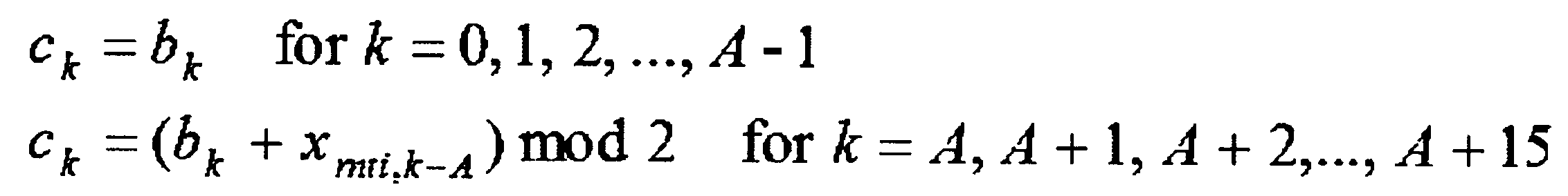
図6は、本実施形態におけるRNTIによるCRCパリティビットのスクランブリングを説明するための別の図である。図6に示すように、ビット系列<c0,…,cB-1>(B=A+L)は、ビット系列<b0,…,bA-1,bA,…,bA+23>のうちの一部<bA+8,…,bA+23>が、RNTI<xrnti,0,…, xrnti,15>によってスクランブルされることによって与えられてもよい。すなわち、ビット系列<b0,…,bA+L-1>(L=23)におけるCRCパリティビット<bA,…,bA+L-1>(L=23)のうちのビット系列<bA+8,…,bA+L-1>(L=23)が、RNTI<xrnti,0,…, xrnti,15>によってスクランブルされることによって、ビット系列<c0,…,cA+L-1>が与えられ、PDCCHで送受信されてもよい。
FIG. 6 is another diagram for explaining the scrambling of CRC parity bits by the RNTI in this embodiment. As shown in FIG. 6, bit sequence <c 0, ..., c B -1> (B = A + L) , the bit sequence <b 0, ..., b A -1, b A, ..., b A + 23> Of some of the <b a + 8, ..., b a + 23> is, RNTI <x rnti, 0, ..., x rnti, 15> may be provided by being scrambled by. That is, the bit sequence <b A + 8 ,... Among the CRC parity bits <b A ,..., B A + L−1 > (L = 23) in the bit sequence <b 0 ,..., B A + L−1 > (L = 23). , b A + L−1 > (L = 23) is scrambled by RNTI <x rnti, 0 ,..., x rnti, 15 > to give the bit sequence <c 0 ,..., c A + L−1 >. And may be transmitted / received on the PDCCH.
ここで、ビット系列<b0,…,bA-1,bA,…,bA+23>は、DCIのペイロード<a0,…,aA-1>に24ビットCRC<p0,…,pL-1>を付加することによって与えられてもよい。すなわち、ビット系列<b0,…,bA-1>はDCI(DCIのペイロード)であり、ビット系列<bA,…,bA+23>は24ビットCRCであってもよい。すなわち、24ビットCRC<bA,…,bA+23>のうちのビット系列<bA+8,…,bA+23>は、RNTI<xrnti,0,…, xrnti,15>によってスクランブルされてもよい。すなわち、24ビットCRC<bA,…,bA+23>のうちのビット系列<bA,…,bA+7>は、RNTI<xrnti,0,…, xrnti,15>によってスクランブルされなくてもよい。
Here, the bit sequence <b 0, ..., b A -1, b A, ..., b A + 23> , the payload of the DCI <a 0 ,...,a A-1> 24-bit CRC <p 0, ..., It may be given by appending p L-1 >. That is, the bit sequence <b 0 ,..., B A-1 > may be DCI (DCI payload), and the bit sequence <b A ,..., B A + 23 > may be a 24-bit CRC. That is, the bit sequence <b A + 8 ,..., B A + 23 > of the 24-bit CRC <b A ,..., B A + 23 > may be scrambled by RNTI <x rnti, 0 , ..., x rnti, 15 >. . That is, the bit sequence <b A ,..., B A + 7 > in the 24-bit CRC <b A ,..., B A + 23 > may not be scrambled by RNTI <x rnti, 0 , ..., x rnti, 15 >. Good.
すなわち、L(CRCパリティビットの数)が24の場合において、ビット系列<c0,…,cA+L-1>は、以下の数式2によって与えられてもよい。
That is, when L (number of CRC parity bits) is 24, the bit sequence <c 0 ,..., C A + L−1 > may be given by Equation 2 below.
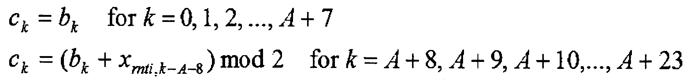
図7は、本実施形態におけるRNTIによるCRCパリティビットのスクランブリングを説明するための別の図である。ここで、ビット系列<c0,…,cB-1>(B=A+L)は、図7に示されるような処理によって与えられ、PDCCHで送受信されてもよい。
FIG. 7 is another diagram for explaining the scrambling of CRC parity bits by the RNTI in this embodiment. Here, the bit sequence <c 0 ,..., C B−1 > (B = A + L) may be given by a process as shown in FIG. 7, and may be transmitted / received on the PDCCH.
すなわち、ビット系列<b0,…,bA-1,bA,…,bA+23>のうちの一部<bA+8,…,bA+23>が、RNTI<xrnti,0,…, xrnti,15>によってスクランブルされてもよい。すなわち、ビット系列<b0,…,bA+L-1>(L=23)におけるCRCパリティビット<bA,…,bA+L-1>(L=23)のうちのビット系列<bA+8,…,bA+L-1>(L=23)が、RNTI<xrnti,0,…, xrnti,15>によってスクランブルされてもよい。
That is, the bit sequences <b 0, ..., b A -1, b A, ..., b A + 23> part of the <b A + 8, ..., b A + 23> is, RNTI <x rnti, 0, ..., It may be scrambled by x rnti, 15 >. That is, the bit sequence <b A + 8 ,... Among the CRC parity bits <b A ,..., B A + L−1 > (L = 23) in the bit sequence <b 0 ,..., B A + L−1 > (L = 23). , b A + L−1 > (L = 23) may be scrambled by RNTI <x rnti, 0 ,..., x rnti, 15 >.
ここで、ビット系列<b0,…,bA-1,bA,…,bA+23>は、DCIのペイロード<a0,…,aA-1>に24ビットCRC<p0,…,pL-1>を付加することによって与えられてもよい。すなわち、ビット系列<b0,…,bA-1>はDCI(DCIのペイロード)であり、ビット系列<bA,…,bA+23>は24ビットCRCであってもよい。すなわち、24ビットCRC<bA,…,bA+23>のうちのビット系列<bA+8,…,bA+23>は、RNTI<xrnti,0,…, xrnti,15>によってスクランブルされてもよい。
Here, the bit sequence <b 0, ..., b A -1, b A, ..., b A + 23> , the payload of the DCI <a 0 ,...,a A-1> 24-bit CRC <p 0, ..., It may be given by appending p L-1 >. That is, the bit sequence <b 0 ,..., B A-1 > may be DCI (DCI payload), and the bit sequence <b A ,..., B A + 23 > may be a 24-bit CRC. That is, the bit sequence <b A + 8 ,..., B A + 23 > of the 24-bit CRC <b A ,..., B A + 23 > may be scrambled by RNTI <x rnti, 0 , ..., x rnti, 15 >. .
また、24ビットCRC<bA,…,bA+23>のうちのビット系列<bA,…,bA+7>は、RNTI<xrnti,0,…, xrnti,15>のうちのビット系列<xrnti,8,…, xrnti,15>によってスクランブルされてもよい。すなわち、24ビットCRC<bA,…,bA+23>のうちのビット系列<bA,…,bA+7>は、RNTI<xrnti,0,…, xrnti,15>のうちの一部<xrnti,8,…, xrnti,15>によってスクランブルされてもよい。
Also, 24-bit CRC <b A, ..., b A + 23> bit sequence of the <b A, ..., b A + 7> is, RNTI <x rnti, 0, ..., x rnti, 15> bit sequence of the < may be scrambled by x rnti, 8 ,..., x rnti, 15 >. That is, 24-bit CRC <b A, ..., b A + 23> bit sequence of the <b A, ..., b A + 7> is, RNTI <x rnti, 0, ..., x rnti, 15> part of the < may be scrambled by x rnti, 8 ,..., x rnti, 15 >.
すなわち、L(CRCパリティビットの数)が24の場合において、ビット系列<c0,…,cA+L-1>は、以下の数式3によって与えられてもよい。
That is, when L (number of CRC parity bits) is 24, the bit sequence <c 0 ,..., C A + L−1 > may be given by Equation 3 below.

図8は、本実施形態におけるRNTIによるCRCパリティビットのスクランブリングを説明するための別の図である。ここで、ビット系列<c0,…,cB-1>(B=A+L)は、図8に示されるような処理によって与えられ、PDCCHで送受信されてもよい。
FIG. 8 is another diagram for explaining the scrambling of CRC parity bits by the RNTI in this embodiment. Here, the bit sequence <c 0 ,..., C B−1 > (B = A + L) may be given by processing as shown in FIG. 8 and may be transmitted / received on the PDCCH.
すなわち、ビット系列<b0,…,bA-1,bA,…,bA+23>のうちの一部<bA+8,…,bA+23>が、RNTI<xrnti,0,…, xrnti,15>によってスクランブルされてもよい。すなわち、ビット系列<b0,…,bA+L-1>(L=23)におけるCRCパリティビット<bA,…,bA+L-1>(L=23)のうちのビット系列<bA+8,…,bA+L-1>(L=23)が、RNTI<xrnti,0,…, xrnti,15>によってスクランブルされてもよい。
That is, the bit sequences <b 0, ..., b A -1, b A, ..., b A + 23> part of the <b A + 8, ..., b A + 23> is, RNTI <x rnti, 0, ..., It may be scrambled by x rnti, 15 >. That is, the bit sequence <b A + 8 ,... Among the CRC parity bits <b A ,..., B A + L−1 > (L = 23) in the bit sequence <b 0 ,..., B A + L−1 > (L = 23). , b A + L−1 > (L = 23) may be scrambled by RNTI <x rnti, 0 ,..., x rnti, 15 >.
ここで、ビット系列<b0,…,bA-1,bA,…,bA+23>は、DCIのペイロード<a0,…,aA-1>に24ビットCRC<p0,…,pL-1>を付加することによって与えられてもよい。すなわち、ビット系列<b0,…,bA-1>はDCI(DCIのペイロード)であり、ビット系列<bA,…,bA+23>は24ビットCRCであってもよい。すなわち、24ビットCRC<bA,…,bA+23>のうちのビット系列<bA+8,…,bA+23>は、RNTI<xrnti,0,…, xrnti,15>によってスクランブルされてもよい。
Here, the bit sequence <b 0, ..., b A -1, b A, ..., b A + 23> , the payload of the DCI <a 0 ,...,a A-1> 24-bit CRC <p 0, ..., It may be given by appending p L-1 >. That is, the bit sequence <b 0 ,..., B A-1 > may be DCI (DCI payload), and the bit sequence <b A ,..., B A + 23 > may be a 24-bit CRC. That is, the bit sequence <b A + 8 ,..., B A + 23 > of the 24-bit CRC <b A ,..., B A + 23 > may be scrambled by RNTI <x rnti, 0 , ..., x rnti, 15 >. .
また、24ビットCRC<bA,…,bA+23>のうちのビット系列<bA,…,bA+7>は、RNTI<xrnti,0,…, xrnti,15>のうちのビット系列<xrnti,8,…, xrnti,15>、および、RNTI<xrnti,0,…, xrnti,15>のうちのビット系列<xrnti,0,…, xrnti,7>によってスクランブルされてもよい。すなわち、24ビットCRC<bA,…,bA+23>のうちのビット系列<bA,…,bA+7>は、RNTI<xrnti,0,…, xrnti,15>のうちの一部<xrnti,8,…, xrnti,15>、および、RNTI<xrnti,0,…, xrnti,15>のうちの残り<xrnti,0,…, xrnti,7>によってスクランブルされてもよい。
Also, the bit sequence <b A ,..., B A + 7 > in the 24-bit CRC <b A ,..., B A + 23 > is the bit sequence <RNTI <x rnti, 0 ,..., X rnti, 15 >< x rnti, 8, ..., x rnti, 15>, and, RNTI <x rnti, 0, ..., x rnti, 15 bit sequence <x RNTI, 0 of>, ..., are scrambled by x RNTI, 7> May be. That is, 24-bit CRC <b A, ..., b A + 23> bit sequence of the <b A, ..., b A + 7> is, RNTI <x rnti, 0, ..., x rnti, 15> part of the < x rnti, 8 , ..., x rnti, 15 > and scrambled by the remaining <x rnti, 0 , ..., x rnti, 7 > of RNTI <x rnti, 0 , ..., x rnti, 15 > Also good.
すなわち、L(CRCパリティビットの数)が24の場合において、ビット系列<c0,…,cA+L-1>は、以下の数式4によって与えられてもよい。
That is, when L (number of CRC parity bits) is 24, the bit sequence <c 0 ,..., C A + L−1 > may be given by Equation 4 below.
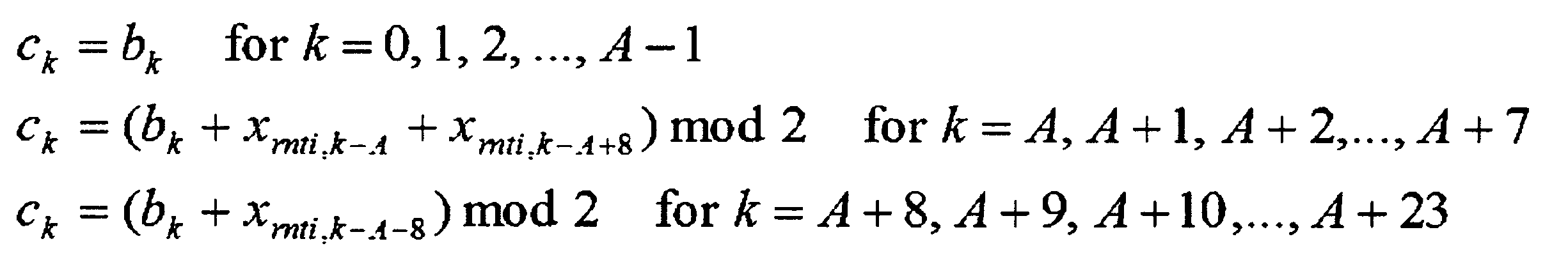
上述のように、RNTIによってスクランブルされるCRCパリティビットの数を増加することによって、端末装置1が、他の端末装置1に対するRNTIによってスクランブルされるCRCパリティビットを含むPDCCHを、該端末装置1に対するRNTIによってスクランブルされるCRCパリティビットを含むPDCCHだと誤って判定してしまう確率を下げることができる。
As described above, by increasing the number of CRC parity bits scrambled by the RNTI, the terminal device 1 transmits the PDCCH including the CRC parity bits scrambled by the RNTI for the other terminal device 1 to the terminal device 1. The probability of erroneously determining that the PDCCH includes CRC parity bits that are scrambled by RNTI can be reduced.
ここで、CRCパリティビットの数を増加することによって、PDCCHでの送信に対する符号化率の低下、および/または、PDCCHでの送信に対して必要なリソース量の増加をもたらす。したがって、上述のように、所定の条件に応じて、対応するDCIフォーマット(DCI:下りリンク制御情報でもよい)に付加されるCRCパリティビットの数を切り替えることによって、基地局装置3と端末装置1において効率的に通信することが可能となる。
Here, increasing the number of CRC parity bits causes a decrease in the coding rate for transmission on the PDCCH and / or an increase in the amount of resources required for transmission on the PDCCH. Therefore, as described above, the base station apparatus 3 and the terminal apparatus 1 are switched by switching the number of CRC parity bits added to the corresponding DCI format (DCI: may be downlink control information) according to a predetermined condition. It becomes possible to communicate efficiently.
図9は、本実施形態におけるCRCパリティビットが付加される下りリンク制御情報を説明するための図である。図9の上段に示される下りリンク制御情報は、24ビットCRCが付加される下りリンク制御情報を示している。また、図9の下段に示される下りリンク制御情報は、16ビットCRCが付加される下りリンク制御情報を示している。
FIG. 9 is a diagram for explaining downlink control information to which CRC parity bits are added in the present embodiment. The downlink control information shown in the upper part of FIG. 9 indicates downlink control information to which a 24-bit CRC is added. Also, the downlink control information shown in the lower part of FIG. 9 indicates downlink control information to which a 16-bit CRC is added.
図9において、ビット系列<b0,…,bA-1>は、第1の端末装置1に対するDCI(下りリンク制御情報)を示している。また、ビット系列<bA,…,bA+23>は、24ビットCRCを示している。また、ビット系列<xrnti,0,…, xrnti,15>は、第1の端末装置1に割り当てられたRNTIを示している。
In FIG. 9, a bit sequence <b 0 ,..., B A-1 > indicates DCI (downlink control information) for the first terminal apparatus 1. Further, the bit sequence <b A ,..., B A + 23 > indicates a 24-bit CRC. Further, the bit sequence <x rnti, 0 ,..., X rnti, 15 > indicates the RNTI assigned to the first terminal apparatus 1.
また、ビット系列<b’0’,…,b’A’-1>は、第2の端末装置1に対する下りリンク制御情報を示している。また、ビット系列<b’A’,…,b’A’+15>は、16ビットCRCを示している。また、ビット系列<x’rnti,0,…, x’rnti,15>は、第2の端末装置1に割り当てられたRNTIを示している。
Further, the bit sequence <b ′ 0 ′ ,..., B ′ A′−1 > indicates downlink control information for the second terminal apparatus 1. Further, the bit sequence <b ′ A ′ ,..., B ′ A ′ + 15 > indicates a 16-bit CRC. Further, the bit sequence <x ′ rnti, 0 ,..., X ′ rnti, 15 > indicates the RNTI assigned to the second terminal apparatus 1.
ここで、24ビットCRC<bA,…,bA+23>のうちのビット系列<bA,…,bA+15>は、RNTI<xrnti,0,…, xrnti,15>によってスクランブルされてもよい。すなわち、24ビットCRC<bA,…,bA+23>のうちのビット系列<bA+16,…,bA+23>は、RNTI<xrnti,0,…, xrnti,15>のうちの一部<xrnti,8,…, xrnti,15>、および、RNTI<xrnti,0,…, xrnti,15>のうちの残り<xrnti,0,…, xrnti,7>によってスクランブルされてもよい。
Here, 24-bit CRC <b A, ..., b A + 23> bit sequence of the <b A, ..., b A + 15> is, RNTI <x rnti, 0, ..., x rnti, 15> be scrambled by Good. That is, 24-bit CRC <b A, ..., b A + 23> bit sequence of the <b A + 16, ..., b A + 23> is, RNTI <x rnti, 0, ..., x rnti, 15> part of the < x rnti, 8 ,..., x rnti, 15 > and scrambled by the remaining <x rnti, 0 , ..., x rnti, 7 > of RNTI <x rnti, 0 , ..., x rnti, 15 > Also good.
また、16ビットCRC<b’A’,…,b’A’+15>は、RNTI<x’rnti,0,…, x’rnti,15>によってスクランブルされてもよい。
Also, 16-bit CRC <b 'A', ... , b 'A' + 15> is, RNTI <x 'rnti, 0 , ..., x' rnti, 15> may be scrambled by.
ここで、第2の端末装置1に対して、第1の端末装置1に対するRNTIとは異なるRNTIを割り当てたとしても、第1の端末装置1に対する24ビットCRCのうちの後半の16ビット<bA+8,…,bA+23>に対して適用されるスクランブリングが、第2の端末装置1に対する16ビットCRC<b’A’,…,b’A’+15>に対して適用されるスクランブリングと同じになってしまうことがある。この場合においては、第2の端末装置1が、第1の端末装置1宛てのPDCCHを、第2の端末装置1のPDCCHとして検出してしまう確率が上がってしまう。
Here, even if an RNTI different from the RNTI for the first terminal device 1 is assigned to the second terminal device 1, the latter 16 bits of the 24-bit CRC for the first terminal device 1 <b Scrambling applied to A + 8 ,..., B A + 23 > is applied to 16-bit CRC <b ′ A ′ ,..., B ′ A ′ + 15 > for the second terminal device 1 It may be the same. In this case, the probability that the second terminal apparatus 1 detects the PDCCH addressed to the first terminal apparatus 1 as the PDCCH of the second terminal apparatus 1 increases.
例えば、第1の端末装置1に対してRNTI<1,1,1,1,1,1,1,1,1,1,1,1,1,1,1,1>を割り当て、第2の端末装置1に対してRNTI<1,1,1,1,1,1,1,1,0,0,0,0,0,0,0,0>を割り当てた場合において、第1の端末装置1に対する24ビットCRCのうちの後半の16ビット、および、第2の端末装置1に対する16ビットCRCは、ともに、ビット系列<1,1,1,1,1,1,1,1,0,0,0,0,0,0,0,0>によってスクランブルされる。
For example, RNTI <1,1,1,1,1,1,1,1,1,1,1,1,1,1,1,1> is assigned to the first terminal device 1 and the second When RNTI <1,1,1,1,1,1,1,1,0,0,0,0,0,0,0,0,0> is assigned to the terminal device 1 of The latter 16 bits of the 24-bit CRC for the terminal device 1 and the 16-bit CRC for the second terminal device 1 both have a bit sequence <1,1,1,1,1,1,1,1,1. 0,0,0,0,0,0,0,0>.
そこで、基地局装置3は、第1の端末装置1に対する24ビットCRCのうちの後半の16ビット<bA+8,…,bA+23>に対して適用されるスクランブリングが、第2の端末装置1に対する16ビットCRC<b’A’,…,b’A’+15>に対して適用されるスクランブリングと同じにならないように、第1の端末装置1および第2の端末装置1のそれぞれに対してRNTIを割り当ててもよい。
Therefore, the base station apparatus 3 performs scrambling applied to the second half 16 bits <b A + 8 ,..., B A + 23 > of the 24-bit CRC for the first terminal apparatus 1. For each of the first terminal apparatus 1 and the second terminal apparatus 1 so as not to be the same as the scrambling applied to the 16-bit CRC <b ′ A ′ ,..., B ′ A ′ + 15 > RNTI may be assigned.
また、図6、図7、および、図8で示した例のように、第1の端末装置1に対する24ビットCRCのうちの後半の16ビット<bA+8,…,bA+23>が、第1の端末装置1に対して割り当てられたRNTI<xrnti,0,…, xrnti,15>によってスクランブルされることによって、第2の端末装置1に対して、第1の端末装置1に対して割り当てたRNTIとは異なるRNTIを割り当てた場合、第1の端末装置1に対する24ビットCRCのうちの後半の16ビット<bA+8,…,bA+23>に対して適用されるスクランブリングと、第2の端末装置1に対する16ビットCRC<b’A’,…,b’A’+15>に対して適用されるスクランブリングを、必ず異なるようにすることが可能となる。
Further, as in the example shown in FIGS. 6, 7, and 8, the last 16 bits <b A + 8 ,..., B A + 23 > of the 24-bit CRC for the first terminal device 1 are the first Are scrambled by RNTI <x rnti, 0 ,..., X rnti, 15 > assigned to the terminal device 1 of the second terminal device 1 and the first terminal device 1. When an RNTI different from the allocated RNTI is assigned, scrambling applied to the latter 16 bits <b A + 8 ,..., B A + 23 > of the 24-bit CRC for the first terminal apparatus 1, The scrambling applied to the 16-bit CRC <b ′ A ′ ,..., B ′ A ′ + 15 > for the terminal device 1 can be made different.
上述のような動作を実行することによって、基地局装置3と端末装置1において、効率的に通信することが可能となる。
By executing the operation as described above, the base station device 3 and the terminal device 1 can communicate efficiently.
以下、本実施形態におけるUE送信アンテナ選択について説明する。ここで、UE送信アンテナ選択には、閉ループUE送信アンテナ選択、および、開ループUE送信アンテナ選択が含まれてもよい。
Hereinafter, UE transmission antenna selection in this embodiment will be described. Here, the UE transmit antenna selection may include closed loop UE transmit antenna selection and open loop UE transmit antenna selection.
例えば、UE送信アンテナ選択は、端末装置1によって実行されてもよい。また、UE送信アンテナ選択は、PUSCH、PUSCHに関するDMRS、および、SRSに対して適用されてもよい。または、UE送信アンテナ選択は、PUCCH、PUCCHに関するDMRS、および、PRACHに対して適用されなくてもよい。ここで、PUCCH、PUCCHに関するDMRS、および、PRACHは、第1の送信アンテナポートを用いて送信されてもよい。
For example, UE transmission antenna selection may be performed by the terminal device 1. Moreover, UE transmission antenna selection may be applied with respect to PUSCH, DMRS regarding PUSCH, and SRS. Or UE transmission antenna selection may not be applied with respect to PUCCH, DMRS regarding PUCCH, and PRACH. Here, PUCCH, DMRS related to PUCCH, and PRACH may be transmitted using the first transmission antenna port.
また、UE送信アンテナ選択は、上位層のパラメータ(ue-TransmitAntennaSelection)を介して、上位層によって設定されてもよい。すなわち、上位層のパラメータ(ue-TransmitAntennaSelection)は、基地局装置3によって端末装置1に通知されてもよい。
Also, UE transmission antenna selection may be set by the upper layer via an upper layer parameter (ue-TransmitAntennaSelection). That is, the upper layer parameter (ue-TransmitAntennaSelection) may be notified to the terminal device 1 by the base station device 3.
ここで、上位層のパラメータ(ue-TransmitAntennaSelection)は、リリース、または、セットアップを示すために用いられてもよい。例えば、上位層のパラメータ(ue-TransmitAntennaSelection)は、セットアップに対して、UE送信アンテナ選択の制御が閉ループであるか開ループであるかを示すために用いられてもよい。また、受信された上位層のパラメータ(ue-TransmitAntennaSelection)がリリースを示す場合には、UE送信アンテナ選択は、端末装置1によって無効にされてもよい。
Here, the upper layer parameter (ue-TransmitAntennaSelection) may be used to indicate release or setup. For example, an upper layer parameter (ue-TransmitAntennaSelection) may be used to indicate to the setup whether the control of UE transmit antenna selection is closed loop or open loop. Further, when the received upper layer parameter (ue-TransmitAntennaSelection) indicates release, UE transmission antenna selection may be invalidated by the terminal device 1.
また、受信された上位層のパラメータ(ue-TransmitAntennaSelection)によってUE送信アンテナ選択の制御が閉ループであることが示される場合には、上位層によって閉ループUE送信アンテナ選択が有効にされてもよい。また、受信された上位層のパラメータ(ue-TransmitAntennaSelection)によってUE送信アンテナ選択の制御が開ループであることが示される場合には、上位層によって開ループUE送信アンテナ選択が有効にされてもよい。
Also, when the received upper layer parameter (ue-TransmitAntennaSelection) indicates that the control of UE transmission antenna selection is closed loop, the higher layer may enable closed loop UE transmission antenna selection. Also, if the received upper layer parameter (ue-TransmitAntennaSelection) indicates that the UE transmission antenna selection control is open loop, the upper layer may enable the open loop UE transmission antenna selection. .
ここで、UE送信アンテナ選択が端末装置1によって無効にされている場合には、端末装置1は、第1の送信アンテナポートを用いて、上述したような、上りリンクの信号を送信してもよい。
Here, when the UE transmission antenna selection is disabled by the terminal device 1, the terminal device 1 may transmit the uplink signal as described above using the first transmission antenna port. Good.
また、上位層によって開ループUE送信アンテナ選択が有効にされている場合には、PUSCHおよび/またはSRSのための送信アンテナ(送信アンテナポート)は、端末装置1自身によって選択されてもよい。
Further, when the open-loop UE transmission antenna selection is enabled by the upper layer, the transmission antenna (transmission antenna port) for PUSCH and / or SRS may be selected by the terminal device 1 itself.
また、上位層によって閉ループUE送信アンテナ選択が有効にされている場合には、端末装置1は、基地局装置3から受信した最新の送信アンテナ選択コマンド(most recent command)を参照することによって、PUSCHのための送信アンテナポートを選択してもよい。
In addition, when the closed-loop UE transmission antenna selection is enabled by the upper layer, the terminal apparatus 1 refers to the latest transmission antenna selection command (most recent command) received from the base station device 3 to determine PUSCH. A transmit antenna port for may be selected.
ここで、送信アンテナ選択コマンドは、CRCパリティビットに対するアンテナ選択マスクによって通知されてもよい。すなわち、「送信アンテナ選択コマンド」は、「アンテナ選択マスク」と同一であってもよい。
Here, the transmission antenna selection command may be notified by an antenna selection mask for the CRC parity bit. That is, the “transmit antenna selection command” may be the same as the “antenna selection mask”.
すなわち、基地局装置3は、アンテナ選択マスクによって、PUSCHのための送信アンテナポートを端末装置1に通知する。また、基地局装置3は、アンテナ選択マスクを選択し、選択したアンテナ選択マスクによってCRCパリティビットをスクランブルしてもよい。例えば、上位層によって閉ループUE送信アンテナ選択が有効にされている場合には、端末装置1は、アンテナ選択マスクによってスクランブルされたCRCパリティビットに基づいて、基地局装置3によって選択されたアンテナ選択マスクを特定(決定)してもよい。
That is, the base station apparatus 3 notifies the terminal apparatus 1 of the transmission antenna port for PUSCH by the antenna selection mask. Moreover, the base station apparatus 3 may select an antenna selection mask and scramble the CRC parity bit with the selected antenna selection mask. For example, when closed-loop UE transmission antenna selection is enabled by the upper layer, the terminal device 1 uses the antenna selection mask selected by the base station device 3 based on the CRC parity bits scrambled by the antenna selection mask. May be specified (determined).
図10は、本実施形態における16ビットCRCに対するアンテナ選択マスクを説明するための図である。図10において、16ビットCRC<bA,…,bA+15>が、RNTI<xrnti,0,…, xrnti,15>およびアンテナ選択マスク<xAS,0,…, xAS,15>によってスクランブルされることが示されている。ここで、図10における、それ以外の説明は、図5と同様であるので、省略する。
FIG. 10 is a diagram for explaining an antenna selection mask for 16-bit CRC in the present embodiment. In FIG. 10, 16-bit CRC <b A ,..., B A + 15 > is represented by RNTI <x rnti, 0 , ..., x rnti, 15 > and antenna selection mask <x AS, 0 , ..., x AS, 15 >. It is shown to be scrambled. Here, the other descriptions in FIG. 10 are the same as those in FIG.
図10に示されるように、L(CRCパリティビットの数)が16の場合において、ビット系列<c0,…,cA+L-1>は、以下の数式5によって与えられてもよい。
As shown in FIG. 10, when L (number of CRC parity bits) is 16, the bit sequence <c 0 ,..., C A + L−1 > may be given by Equation 5 below.
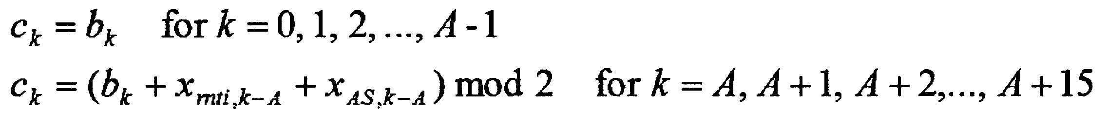
図11は、本実施形態における24ビットCRCに対するアンテナ選択マスクを説明するための図である。図11に示されるように、24ビットCRC<bA,…,bA+23>のうちのビット系列<bA,…,bA+7>が、RNTI<xrnti,0,…, xrnti,15>のうちの一部<xrnti,8,…, xrnti,15>、RNTI<xrnti,0,…, xrnti,15>のうちの残り<xrnti,0,…, xrnti,7>、および、アンテナ選択マスク<xAS,0,…, xAS,15>によってスクランブルされてもよい。ここで、図11における、それ以外の説明は、図8と同様であるので、省略する。
FIG. 11 is a diagram for explaining an antenna selection mask for 24-bit CRC in the present embodiment. As shown in FIG. 11, 24-bit CRC <b A, ..., b A + 23> bit sequence of the <b A, ..., b A + 7> is, RNTI <x rnti, 0, ..., x rnti, 15> some of the <x rnti, 8, ..., x rnti, 15>, RNTI <x rnti, 0, ..., x rnti, 15> the rest of the <x rnti, 0, ..., x rnti, 7> , And antenna selection mask <x AS, 0 ,..., X AS, 15 >. Here, the other description in FIG. 11 is the same as FIG.
図11に示されるように、L(CRCパリティビットの数)が24の場合において、ビット系列<c0,…,cA+L-1>は、以下の数式6によって与えられてもよい。
As shown in FIG. 11, when L (number of CRC parity bits) is 24, the bit sequence <c 0 ,..., C A + L−1 > may be given by Equation 6 below.
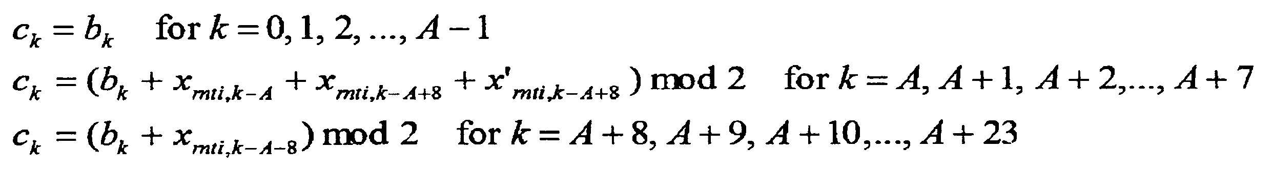
ここで、図10、および、図11に示されるように、16ビットCRCに対して適用される複数のアンテナ選択マスクの第1のセットと、24ビットCRCに対して適用される複数のアンテナ選択マスクの第2のセットは異なってもよい。すなわち、図10、および、図11に示されるように、16ビットCRCに対して適用される複数のアンテナ選択マスクの第1のセット<xAS,0,…, xAS,15>(すなわち、<0,0,0,0,0,0,0,0,0,0,0,0,0,0,0,0>、および、<0,0,0,0,0,0,0,0,0,0,0,0,0,0,0,1>)と、24ビットCRCに対して適用される複数のアンテナ選択マスクの第2のセット<x’AS,0,…, x’AS,7>(すなわち、<0,0,0,0,0,0,0,0>、および、<0,0,0,0,0,0,0,1>)は異なってもよい。
Here, as shown in FIG. 10 and FIG. 11, a first set of multiple antenna selection masks applied to a 16-bit CRC and multiple antenna selections applied to a 24-bit CRC. The second set of masks may be different. That is, as shown in FIG. 10 and FIG. 11, a first set of a plurality of antenna selection masks applied to a 16-bit CRC <x AS, 0 ,..., X AS, 15 > (ie <0,0,0,0,0,0,0,0,0,0,0,0,0,0,0,0> and <0,0,0,0,0,0,0 , 0 , 0 , 0 , 0 , 0 , 0 , 0 , 0 , 1>) and a second set of antenna selection masks applied to the 24-bit CRC <x ′ AS, 0 ,. x ′ AS, 7 > (ie, <0,0,0,0,0,0,0,0> and <0,0,0,0,0,0,0,1>) are different Also good.
例えば、16ビットCRCに対して適用される複数のアンテナ選択マスクの第1のセットは、第1のアンテナ選択マスク(例えば、<0,0,0,0,0,0,0,0,0,0,0,0,0,0,0,0>)、および、第2のアンテナ選択マスク(例えば、<0,0,0,0,0,0,0,0,0,0,0,0,0,0,0,1>)を含んでもよい。ここで、第1のアンテナ選択マスクは、第1の送信アンテナポートを示すために用いられてもよい。また、第2のアンテナ選択マスクは、第2の送信アンテナポートを示すために用いられてもよい。
For example, the first set of antenna selection masks applied to a 16-bit CRC may be a first antenna selection mask (eg, <0,0,0,0,0,0,0,0,0 , 0, 0, 0, 0, 0, 0, 0>) and a second antenna selection mask (eg, <0, 0, 0, 0, 0, 0, 0, 0, 0, 0, 0 , 0, 0, 0, 0, 1>). Here, the first antenna selection mask may be used to indicate the first transmit antenna port. The second antenna selection mask may also be used to indicate the second transmit antenna port.
また、24ビットCRCに対して適用される複数のアンテナ選択マスクの第2のセットは、第3のアンテナ選択マスク(例えば、<0,0,0,0,0,0,0,0>)、および、第4のアンテナ選択マスク(例えば、<0,0,0,0,0,0,0,1>)を含んでもよい。ここで、第3のアンテナ選択マスクは、第1の送信アンテナポートを示すために用いられてもよい。また、第4のアンテナ選択マスクは、第2の送信アンテナポートを示すために用いられてもよい。
The second set of antenna selection masks applied to the 24-bit CRC is a third antenna selection mask (eg, <0, 0, 0, 0, 0, 0, 0, 0>). , And a fourth antenna selection mask (eg, <0, 0, 0, 0, 0, 0, 0, 1>). Here, the third antenna selection mask may be used to indicate the first transmit antenna port. The fourth antenna selection mask may also be used to indicate the second transmit antenna port.
すなわち、CRCパリティビットの数(Lの値)が16の場合には、第1のアンテナ選択マスクによって第1の送信アンテナポートが与えられてもよい。また、CRCパリティビットの数(Lの値)が24の場合には、第3のアンテナ選択マスクによって第1の送信アンテナポートが与えられてもよい。ここで、第1のアンテナ選択マスクと第3のアンテナ選択マスクは、異なっていてもよい。例えば、アンテナ選択マスクのビットの数は、Lが16の場合には16であり、Lが24の場合には8であってもよい。また、アンテナ選択マスクのビットのそれぞれの値は、Lが16の場合とLが24の場合で、異なってもよい。
That is, when the number of CRC parity bits (L value) is 16, the first transmission antenna port may be given by the first antenna selection mask. When the number of CRC parity bits (L value) is 24, the first transmission antenna port may be given by the third antenna selection mask. Here, the first antenna selection mask and the third antenna selection mask may be different. For example, the number of bits in the antenna selection mask may be 16 when L is 16 and may be 8 when L is 24. The values of the bits of the antenna selection mask may be different when L is 16 and L is 24.
同様に、CRCパリティビットの数(Lの値)が16の場合には、第2のアンテナ選択マスクによって第2の送信アンテナポートが与えられてもよい。また、CRCパリティビットの数(Lの値)が24の場合には、第4のアンテナ選択マスクによって第2の送信アンテナポートが与えられてもよい。ここで、第2のアンテナ選択マスクと第4のアンテナ選択マスクは、異なっていてもよい。例えば、アンテナ選択マスクのビットの数は、Lが16の場合には16であり、Lが24の場合には8であってもよい。また、また、アンテナ選択マスクのビットのそれぞれの値は、Lが16の場合とLが24の場合で、異なってもよい。
Similarly, when the number of CRC parity bits (L value) is 16, the second transmission antenna port may be given by the second antenna selection mask. When the number of CRC parity bits (L value) is 24, the second transmission antenna port may be given by the fourth antenna selection mask. Here, the second antenna selection mask and the fourth antenna selection mask may be different. For example, the number of bits in the antenna selection mask may be 16 when L is 16 and may be 8 when L is 24. Also, the values of the bits of the antenna selection mask may be different when L is 16 and L is 24.
ここで、端末装置1は、端末装置1に対して複数のサービングセルが設定されている場合において、1つのサブフレームにおいて、複数の送信アンテナ選択コマンドを受信してもよい。ここで、この場合において、基地局装置3は、1つのサブフレームにおいて、同じ送信アンテナポート(送信アンテナポートの同じ値)を示す複数の送信アンテナ選択コマンドを、複数のサービングセルが設定されている端末装置1へ送信してもよい。すなわち、端末装置1は、1つのサブフレームにおいて複数の送信アンテナ選択コマンドを受信する場合において、該複数の送信アンテナ選択コマンドを用いて同じ送信アンテナポート(送信アンテナポートの同じ値)が示されるとみなしてもよい。
Here, when a plurality of serving cells are set for the terminal device 1, the terminal device 1 may receive a plurality of transmission antenna selection commands in one subframe. In this case, in this case, the base station apparatus 3 uses a plurality of transmission antenna selection commands indicating the same transmission antenna port (the same value of the transmission antenna port) in one subframe, and a terminal in which a plurality of serving cells are set. You may transmit to the apparatus 1. That is, when the terminal apparatus 1 receives a plurality of transmission antenna selection commands in one subframe, the same transmission antenna port (the same value of the transmission antenna port) is indicated using the plurality of transmission antenna selection commands. May be considered.
また、上位層のパラメータ(例えば、RRC層のパラメータ)を用いて閉ループUE送信アンテナ選択が有効にされている場合において、端末装置1は、SRSの送信のカウントされた数を参照することによって、SRSのための送信アンテナポートを選択してもよい。すなわち、SRSの送信のための送信アンテナポートは、基地局装置3によって設定されるSRS送信インスタンス(SRSの送信のためのサブフレーム)によって与えられてもよい。ここで、端末装置1に対して複数のサービングセルが設定されている場合において、基地局装置3は、端末装置1が異なる送信アンテナポートにおいてSRSを同時に送信しないように、SRS送信インスタンスを設定してもよい。
In addition, when closed-loop UE transmission antenna selection is enabled using higher layer parameters (for example, RRC layer parameters), the terminal device 1 refers to the counted number of SRS transmissions, A transmit antenna port for SRS may be selected. That is, the transmission antenna port for SRS transmission may be given by an SRS transmission instance (subframe for SRS transmission) set by the base station apparatus 3. Here, when a plurality of serving cells are set for the terminal device 1, the base station device 3 sets an SRS transmission instance so that the terminal device 1 does not simultaneously transmit SRS in different transmission antenna ports. Also good.
ここで、端末装置1は、複数のタイミングアドバンスグループが設定される場合において、PUSCHとPUCCHの同時送信、PUSCHとSRSの同時送信、PUCCHとSRSの同時送信、PRACHとSRSの同時送信、および、PRACHとPUSCHの同時送信を行ってもよい。すなわち、端末装置1は、複数のタイミングアドバンスグループが設定される場合において、PUSCHとPUCCHの同時送信、PUSCHとSRSの同時送信、PUCCHとSRSの同時送信、PRACHとSRSの同時送信、および、PRACHとPUSCHの同時送信を行うことを期待される。
Here, when a plurality of timing advance groups are set, the terminal device 1 is configured to simultaneously transmit PUSCH and PUCCH, simultaneously transmit PUSCH and SRS, simultaneously transmit PUCCH and SRS, simultaneously transmit PRACH and SRS, and Simultaneous transmission of PRACH and PUSCH may be performed. That is, when a plurality of timing advance groups are set, the terminal device 1 simultaneously transmits PUSCH and PUCCH, simultaneously transmits PUSCH and SRS, simultaneously transmits PUCCH and SRS, simultaneously transmits PRACH and SRS, and PRACH. And PUSCH are expected to be transmitted simultaneously.
また、端末装置1は、複数のPUCCHセルグループが設定される場合において、または、セカンダリーセルにおけるPUCCHでの送信が設定される場合において、PUSCHとPUCCHの同時送信を行ってもよい。また、端末装置1は、複数のPUCCHセルグループが設定される場合において、または、セカンダリーセルにおけるPUCCHでの送信が設定される場合において、PUSCHとPUCCHの同時送信を行うことを期待される。
In addition, when a plurality of PUCCH cell groups are set or when transmission on the PUCCH in the secondary cell is set, the terminal device 1 may perform simultaneous transmission of PUSCH and PUCCH. Further, the terminal device 1 is expected to perform simultaneous transmission of PUSCH and PUCCH when a plurality of PUCCH cell groups are set or when transmission on the PUCCH in the secondary cell is set.
上述のとおり、送信アンテナ選択が適用される上りリンクの信号と、送信アンテナ選択が適用されない上りリンクの信号の同時送信を行うことを端末装置1が期待されるような場合、基地局装置3は、上位層のパラメータ(ue-TransmitAntennaSelection)を介して、端末装置1に対して送信アンテナ選択の無効を指示してもよい。
As described above, when the terminal apparatus 1 is expected to simultaneously transmit an uplink signal to which transmission antenna selection is applied and an uplink signal to which transmission antenna selection is not applied, the base station apparatus 3 The terminal device 1 may be instructed to disable transmission antenna selection via a higher layer parameter (ue-TransmitAntennaSelection).
すなわち、基地局装置3は、送信アンテナ選択が設定された端末装置1に対して、複数のタイミングアドバンスグループ、複数のPUCCHセルグループ、および/または、セカンダリーセルにおけるPUCCHでの送信を設定しなくてもよい。すなわち、基地局装置3は、送信アンテナ選択が設定された端末装置1に対して、MTAを設定しなくてもよい。また、基地局装置3は、送信アンテナ選択が設定された端末装置1に対して、複数のPUCCHセルグループを設定しなくてもよい。また、基地局装置3は、送信アンテナ選択が設定された端末装置1に対して、セカンダリーセルにおけるPUCCHでの送信を設定しなくてもよい。
That is, the base station apparatus 3 does not set transmission on the PUCCH in the plurality of timing advance groups, the plurality of PUCCH cell groups, and / or the secondary cell to the terminal apparatus 1 for which transmission antenna selection is set. Also good. That is, the base station apparatus 3 may not set the MTA for the terminal apparatus 1 for which the transmission antenna selection is set. Moreover, the base station apparatus 3 does not need to set a some PUCCH cell group with respect to the terminal device 1 with which transmission antenna selection was set. Moreover, the base station apparatus 3 does not need to set the transmission by PUCCH in a secondary cell with respect to the terminal device 1 with which transmission antenna selection was set.
ここで、基地局装置3は、複数のタイミングアドバンスグループを設定した端末装置1に対して、複数のPUCCHセルグループを設定してもよい。また、基地局装置3は、複数のタイミングアドバンスグループを設定した端末装置1に対して、セカンダリーセルにおけるPUCCHでの送信を設定してもよい。すなわち、基地局装置3は、MTAを設定した端末装置1に対して、複数のPUCCHセルグループを設定してもよい。また、基地局装置3は、MTAを設定した端末装置1に対して、複数のPUCCHセルグループを設定してもよい。
Here, the base station apparatus 3 may set a plurality of PUCCH cell groups for the terminal apparatus 1 for which a plurality of timing advance groups are set. Moreover, the base station apparatus 3 may set the transmission by PUCCH in a secondary cell with respect to the terminal device 1 which set the several timing advance group. That is, the base station apparatus 3 may set a plurality of PUCCH cell groups for the terminal apparatus 1 for which MTA is set. Moreover, the base station apparatus 3 may set several PUCCH cell groups with respect to the terminal device 1 which set MTA.
また、端末装置1は、送信アンテナ選択が設定された場合において、複数のタイミングアドバンスグループ、複数のPUCCHセルグループ、および/または、セカンダリーセルにおけるPUCCHでの送信が設定されることを期待されなくてもよい。すなわち、端末装置1は、送信アンテナ選択が設定された場合において、MTAが設定されることを期待されなくてもよい。また、端末装置1は、送信アンテナ選択が設定された場合において、複数のPUCCHセルグループが設定されることを期待されなくてもよい。また、端末装置1は、送信アンテナ選択が設定された場合において、セカンダリーセルにおけるPUCCHでの送信が設定されることを期待されなくてもよい。
Further, when the transmission antenna selection is set, the terminal device 1 is not expected to be set to transmit on the PUCCH in a plurality of timing advance groups, a plurality of PUCCH cell groups, and / or a secondary cell. Also good. That is, the terminal device 1 may not be expected to set the MTA when the transmission antenna selection is set. Further, the terminal device 1 may not be expected to set a plurality of PUCCH cell groups when the transmission antenna selection is set. Moreover, when the transmission antenna selection is set, the terminal device 1 may not be expected to set transmission on the PUCCH in the secondary cell.
ここで、端末装置1は、複数のタイミングアドバンスグループが設定された場合において、複数のPUCCHセルグループが設定されることを期待されてもよい。また、端末装置1は、複数のタイミングアドバンスグループが設定された場合において、セカンダリーセルにおけるPUCCHでの送信が設定されることを期待されてもよい。すなわち、端末装置1は、MTAが設定された場合において、複数のPUCCHセルグループが設定されることを期待されてもよい。また、基地局装置3は、MTAが設定された場合において、複数のPUCCHセルグループが設定されることを期待されてもよい。
Here, the terminal device 1 may be expected to set a plurality of PUCCH cell groups when a plurality of timing advance groups are set. Moreover, the terminal device 1 may be expected to set transmission on the PUCCH in the secondary cell when a plurality of timing advance groups are set. That is, when the MTA is set, the terminal device 1 may be expected to set a plurality of PUCCH cell groups. Further, the base station apparatus 3 may be expected to set a plurality of PUCCH cell groups when the MTA is set.
ここで、端末装置1は、端末装置1が種々の機能をサポートするかどうかを示すために用いられる機能情報(能力情報:capability informationとも称する)を、基地局装置3に送信してもよい。ここで、機能情報は、複数の機能のそれぞれに対して、機能が成功裏にテストされたかどうかを示してもよい。また、機能情報は、端末装置1が所定の機能をサポートするかどうかを示してもよい。
Here, the terminal apparatus 1 may transmit function information (also referred to as capability information) used to indicate whether the terminal apparatus 1 supports various functions to the base station apparatus 3. Here, the function information may indicate whether the function has been successfully tested for each of the plurality of functions. The function information may indicate whether the terminal device 1 supports a predetermined function.
例えば、機能情報は、(i)端末装置1が送信アンテナ選択をサポートするかどうか、(ii)端末装置1がMTA(Multiple Timing Advance)をサポートするかどうか、(iii)端末装置1が複数のPUCCHセルグループをサポートするかどうか、および/または、(iv)端末装置1がセカンダリーセルにおけるPUCCHでの送信をサポートするかどうか、を示すために用いられてもよい。
For example, the function information includes (i) whether the terminal device 1 supports transmission antenna selection, (ii) whether the terminal device 1 supports MTA (Multiple Timing Advance), or (iii) a plurality of terminal devices 1 It may be used to indicate whether to support the PUCCH cell group and / or (iv) whether the terminal device 1 supports transmission on the PUCCH in the secondary cell.
例えば、端末装置1によって送信される機能情報が、(i)端末装置1が送信アンテナ選択をサポートすること、および、(ii)端末装置1がMTA(Multiple Timing Advance)をサポートすること、を示していた場合であったとしても、基地局装置3は、送信アンテナ選択を設定した端末装置1に対して、複数のタイミングアドバンスグループを設定しなくてもよい。すなわち、端末装置1によって送信される機能情報が、(i)端末装置1が送信アンテナ選択をサポートすること、および、(ii)端末装置1がMTA(Multiple Timing Advance)をサポートすること、を示していた場合であったとしても、送信アンテナ選択が設定された端末装置1は、複数のタイミングアドバンスグループが設定されることを期待されなくてもよい。
For example, the function information transmitted by the terminal device 1 indicates that (i) the terminal device 1 supports transmission antenna selection, and (ii) the terminal device 1 supports MTA (Multiple Timing Advance). Even if this is the case, the base station apparatus 3 does not have to set a plurality of timing advance groups for the terminal apparatus 1 that has set the transmission antenna selection. That is, the function information transmitted by the terminal device 1 indicates that (i) the terminal device 1 supports transmission antenna selection and (ii) the terminal device 1 supports MTA (Multiple Timing Advance). Even if this is the case, the terminal device 1 in which the transmission antenna selection is set may not be expected to set a plurality of timing advance groups.
また、端末装置1によって送信される機能情報が、(i)端末装置1が送信アンテナ選択をサポートすること、および、(ii)端末装置1がセカンダリーセルにおけるPUCCHでの送信をサポートすること、を示していた場合であったとしても、基地局装置3は、送信アンテナ選択を設定した端末装置1に対して、セカンダリーセルにおけるPUCCHでの送信を設定しなくてもよい。すなわち、端末装置1によって機能情報が、(i)端末装置1が送信アンテナ選択をサポートすること、および、(ii)端末装置1がセカンダリーセルにおけるPUCCHでの送信をサポートすること、を示していた場合であったとしても、送信アンテナ選択が設定された端末装置1は、セカンダリーセルにおけるPUCCHでの送信が設定されることを期待されなくてもよい。
In addition, the function information transmitted by the terminal device 1 includes (i) that the terminal device 1 supports transmission antenna selection, and (ii) that the terminal device 1 supports transmission on the PUCCH in the secondary cell. Even if it is the case where it showed, the base station apparatus 3 does not need to set the transmission by PUCCH in a secondary cell with respect to the terminal device 1 which set transmission antenna selection. That is, the function information by the terminal device 1 indicates that (i) the terminal device 1 supports transmission antenna selection, and (ii) the terminal device 1 supports transmission on the PUCCH in the secondary cell. Even if it is a case, the terminal device 1 to which transmission antenna selection is set may not be expected to be set to transmit on the PUCCH in the secondary cell.
基地局装置3と端末装置1が上述のような動作を実行することによって、端末装置1が、上位層によってUE送信アンテナ選択が有効にされた場合においても、異なる送信アンテナポートを用いて上りリンクの信号を同時に送信する必要がなくなり、UE送信アンテナ選択を実行する能力を持つ端末装置1におけるRF(Radio Frequency)部の構成を簡略化することができる。また、これにより、基地局装置3と端末装置1において、効率的に通信することが可能となる。
When the base station apparatus 3 and the terminal apparatus 1 perform the operations as described above, the terminal apparatus 1 uses the different transmission antenna ports to perform uplink even when UE transmission antenna selection is enabled by the upper layer. It is no longer necessary to transmit the signals simultaneously, and the configuration of an RF (Radio Frequency) unit in the terminal device 1 having the ability to perform UE transmission antenna selection can be simplified. This also enables efficient communication between the base station device 3 and the terminal device 1.
以上、本実施形態について、図面を参照して記述してきたが、具体的な構成は上述の記載に限られるものではなく、この発明の要旨を逸脱しない範囲の設計変更等も含まれる。また、本実施形態は、上述に記載の方法/処理を適宜組み合わせて得られる実施形態についても本発明の技術的範囲に含まれる。
As described above, the present embodiment has been described with reference to the drawings. However, the specific configuration is not limited to the above description, and includes design changes and the like without departing from the gist of the present invention. The present embodiment also includes embodiments obtained by appropriately combining the methods / processes described above within the technical scope of the present invention.
以下、本実施形態における装置の構成について説明する。
Hereinafter, the configuration of the apparatus according to the present embodiment will be described.
図12は、本実施形態における端末装置1の構成を示す概略ブロック図である。図に示すように、端末装置1は、上位層処理部101、制御部103、受信部105、送信部107と送受信アンテナ部109を含んで構成される。また、上位層処理部101は、無線リソース制御部1011、スケジューリング情報解釈部1013、および、送信電力制御部1015を含んで構成される。また、受信部105は、復号化部1051、復調部1053、多重分離部1055、無線受信部1057とチャネル測定部1059を含んで構成される。また、送信部107は、符号化部1071、変調部1073、多重部1075、無線送信部1077と上りリンク参照信号生成部1079を含んで構成される。
FIG. 12 is a schematic block diagram showing the configuration of the terminal device 1 in the present embodiment. As shown in the figure, the terminal device 1 includes an upper layer processing unit 101, a control unit 103, a receiving unit 105, a transmitting unit 107, and a transmitting / receiving antenna unit 109. The upper layer processing unit 101 includes a radio resource control unit 1011, a scheduling information interpretation unit 1013, and a transmission power control unit 1015. The reception unit 105 includes a decoding unit 1051, a demodulation unit 1053, a demultiplexing unit 1055, a radio reception unit 1057, and a channel measurement unit 1059. The transmission unit 107 includes an encoding unit 1071, a modulation unit 1073, a multiplexing unit 1075, a radio transmission unit 1077, and an uplink reference signal generation unit 1079.
上位層処理部101は、ユーザーの操作等により生成された上りリンクデータ(トランスポートブロック)を、送信部107に出力する。また、上位層処理部101は、媒体アクセス制御(MAC: Medium Access Control)層、パケットデータ統合プロトコル(Packet Data Convergence Protocol: PDCP)層、無線リンク制御(Radio Link Control: RLC)層、無線リソース制御(Radio Resource Control: RRC)層の処理を行なう。
The upper layer processing unit 101 outputs uplink data (transport block) generated by a user operation or the like to the transmission unit 107. The upper layer processing unit 101 includes a medium access control (MAC: Medium Access Control) layer, a packet data integration protocol (Packet Data Convergence Protocol: PDCP) layer, a radio link control (Radio Link Control: RLC) layer, and radio resource control. Process the (Radio Resource Control: RRC) layer.
上位層処理部101が備える無線リソース制御部1011は、自装置の各種設定情報/パラメータの管理をする。無線リソース制御部1011は、基地局装置3から受信した上位層の信号に基づいて各種設定情報/パラメータをセットする。すなわち、無線リソース制御部1011は、基地局装置3から受信した各種設定情報/パラメータを示す情報に基づいて各種設定情報/パラメータをセットする。また、無線リソース制御部1011は、上りリンクの各チャネルに配置される情報を生成し、送信部107に出力する。無線リソース制御部1011を設定部1011とも称する。
The radio resource control unit 1011 included in the upper layer processing unit 101 manages various setting information / parameters of the own device. The radio resource control unit 1011 sets various setting information / parameters based on the upper layer signal received from the base station apparatus 3. That is, the radio resource control unit 1011 sets various setting information / parameters based on information indicating various setting information / parameters received from the base station apparatus 3. Also, the radio resource control unit 1011 generates information arranged in each uplink channel and outputs the information to the transmission unit 107. The radio resource control unit 1011 is also referred to as a setting unit 1011.
ここで、上位層処理部101が備えるスケジューリング情報解釈部1013は、受信部105を介して受信したDCIフォーマット(スケジューリング情報)の解釈をし、前記DCIフォーマットを解釈した結果に基づき、受信部105、および送信部107の制御を行なうために制御情報を生成し、制御部103に出力する。
Here, the scheduling information interpretation unit 1013 included in the upper layer processing unit 101 interprets the DCI format (scheduling information) received via the reception unit 105, and based on the interpretation result of the DCI format, the reception unit 105, Control information is generated to control the transmission unit 107 and output to the control unit 103.
また、上位層処理部101が備える送信電力制御部1015は、無線リソース制御部1011によって管理されている各種設定情報/パラメータ、TPCコマンドなどに基づいて、PUSCHおよびPUCCHでの送信に対する送信電力の制御を行う。
The transmission power control unit 1015 included in the upper layer processing unit 101 controls transmission power for transmission on PUSCH and PUCCH based on various setting information / parameters, TPC commands, and the like managed by the radio resource control unit 1011. I do.
また、制御部103は、上位層処理部101からの制御情報に基づいて、受信部105、および送信部107の制御を行なう制御信号を生成する。制御部103は、生成した制御信号を受信部105、および送信部107に出力して受信部105、および送信部107の制御を行なう。
Further, the control unit 103 generates a control signal for controlling the receiving unit 105 and the transmitting unit 107 based on the control information from the higher layer processing unit 101. Control unit 103 outputs the generated control signal to receiving unit 105 and transmitting unit 107 to control receiving unit 105 and transmitting unit 107.
また、受信部105は、制御部103から入力された制御信号に従って、送受信アンテナ部109を介して基地局装置3から受信した受信信号を、分離、復調、復号し、復号した情報を上位層処理部101に出力する。
The receiving unit 105 also separates, demodulates, and decodes the received signal received from the base station apparatus 3 via the transmission / reception antenna unit 109 according to the control signal input from the control unit 103, and processes the decoded information in an upper layer process. Output to the unit 101.
また、無線受信部1057は、送受信アンテナ部109を介して受信した下りリンクの信号を、直交復調によりベースバンド信号に変換し(ダウンコンバート: down covert)、不要な周波数成分を除去し、信号レベルが適切に維持されるように増幅レベルを制御し、受信した信号の同相成分および直交成分に基づいて、直交復調し、直交復調されたアナログ信号をディジタル信号に変換する。無線受信部1057は、変換したディジタル信号からCP(Cyclic Prefix)に相当する部分を除去し、CPを除去した信号に対して高速フーリエ変換(Fast Fourier Transform: FFT)を行い、周波数領域の信号を抽出する。
Also, the radio reception unit 1057 converts a downlink signal received via the transmission / reception antenna unit 109 into a baseband signal by orthogonal demodulation (down-conversion: down covert), removes unnecessary frequency components, and reduces the signal level. The amplification level is controlled so as to be properly maintained, and quadrature demodulation is performed based on the in-phase component and the quadrature component of the received signal, and the quadrature demodulated analog signal is converted into a digital signal. The radio reception unit 1057 removes a portion corresponding to CP (Cyclic Prefix) from the converted digital signal, and performs a fast Fourier transform (FFT) on the signal from which the CP has been removed to obtain a frequency domain signal. Extract.
また、多重分離部1055は、抽出した信号をPHICH、PDCCH、EPDCCH、PDSCH、および下りリンク参照信号に、それぞれ分離する。また、多重分離部1055は、チャネル測定部1059から入力された伝搬路の推定値から、PHICH、PDCCH、EPDCCH、およびPDSCHの伝搬路の補償を行なう。また、多重分離部1055は、分離した下りリンク参照信号をチャネル測定部1059に出力する。
Also, the demultiplexing unit 1055 separates the extracted signal into PHICH, PDCCH, EPDCCH, PDSCH, and downlink reference signal. Further, demultiplexing section 1055 compensates the propagation path of PHICH, PDCCH, EPDCCH, and PDSCH from the estimated propagation path value input from channel measurement section 1059. Also, the demultiplexing unit 1055 outputs the demultiplexed downlink reference signal to the channel measurement unit 1059.
また、復調部1053は、PHICHに対して対応する符号を乗算して合成し、合成した信号に対してBPSK(Binary Phase Shift Keying)変調方式の復調を行ない、復号化部1051へ出力する。復号化部1051は、自装置宛てのPHICHを復号し、復号したHARQインディケータを上位層処理部101に出力する。復調部1053は、PDCCHおよび/またはEPDCCHに対して、QPSK変調方式の復調を行ない、復号化部1051へ出力する。復号化部1051は、PDCCHおよび/またはEPDCCHの復号を試み、復号に成功した場合、復号した下りリンク制御情報と下りリンク制御情報が対応するRNTIとを上位層処理部101に出力する。
Also, the demodulating unit 1053 multiplies the PHICH by a corresponding code and synthesizes it, demodulates the synthesized signal using the BPSK (Binary Phase Shift Shift Keying) modulation method, and outputs it to the decoding unit 1051. Decoding section 1051 decodes the PHICH addressed to the own apparatus, and outputs the decoded HARQ indicator to higher layer processing section 101. Demodulation section 1053 performs QPSK modulation demodulation on PDCCH and / or EPDCCH, and outputs the result to decoding section 1051. Decoding section 1051 attempts to decode PDCCH and / or EPDCCH, and outputs the decoded downlink control information and the RNTI corresponding to the downlink control information to higher layer processing section 101 when the decoding is successful.
また、復調部1053は、PDSCHに対して、QPSK(Quadrature Phase Shift Keying)、16QAM(Quadrature Amplitude Modulation)、64QAM等の下りリンクグラントで通知された変調方式の復調を行ない、復号化部1051へ出力する。復号化部1051は、下りリンク制御情報で通知された符号化率に関する情報に基づいて復号を行い、復号した下りリンクデータ(トランスポートブロック)を上位層処理部101へ出力する。
Further, the demodulation unit 1053 demodulates the modulation scheme notified by a downlink grant such as QPSK (Quadrature Phase Shift Keying), 16QAM (Quadrature Amplitude Modulation), 64QAM, etc., and outputs the result to the decoding unit 1051 To do. The decoding unit 1051 performs decoding based on the information regarding the coding rate notified by the downlink control information, and outputs the decoded downlink data (transport block) to the higher layer processing unit 101.
また、チャネル測定部1059は、多重分離部1055から入力された下りリンク参照信号から下りリンクのパスロスやチャネルの状態を測定し、測定したパスロスやチャネルの状態を上位層処理部101へ出力する。また、チャネル測定部1059は、下りリンク参照信号から下りリンクの伝搬路の推定値を算出し、多重分離部1055へ出力する。チャネル測定部1059は、CQI(CSIでもよい)の算出のために、チャネル測定、および/または、干渉測定を行なう。
Also, the channel measurement unit 1059 measures the downlink path loss and channel state from the downlink reference signal input from the demultiplexing unit 1055, and outputs the measured path loss and channel state to the higher layer processing unit 101. Also, channel measurement section 1059 calculates an estimated value of the downlink propagation path from the downlink reference signal, and outputs it to demultiplexing section 1055. The channel measurement unit 1059 performs channel measurement and / or interference measurement in order to calculate CQI (may be CSI).
また、送信部107は、制御部103から入力された制御信号に従って、上りリンク参照信号を生成し、上位層処理部101から入力された上りリンクデータ(トランスポートブロック)を符号化および変調し、PUCCH、PUSCH、および生成した上りリンク参照信号を多重し、送受信アンテナ部109を介して基地局装置3に送信する。また、送信部107は、上りリンク制御情報を送信する。
Further, the transmission unit 107 generates an uplink reference signal according to the control signal input from the control unit 103, encodes and modulates uplink data (transport block) input from the higher layer processing unit 101, PUCCH, PUSCH, and the generated uplink reference signal are multiplexed and transmitted to base station apparatus 3 via transmission / reception antenna section 109. Moreover, the transmission part 107 transmits uplink control information.
また、符号化部1071は、上位層処理部101から入力された上りリンク制御情報を畳み込み符号化、ブロック符号化等の符号化を行う。また、符号化部1071は、PUSCHのスケジューリングに用いられる情報に基づきターボ符号化を行なう。
Also, the encoding unit 1071 performs encoding such as convolutional encoding and block encoding on the uplink control information input from the higher layer processing unit 101. The encoding unit 1071 performs turbo encoding based on information used for PUSCH scheduling.
また、変調部1073は、符号化部1071から入力された符号化ビットをBPSK、QPSK、16QAM、64QAM等の下りリンク制御情報で通知された変調方式または、チャネル毎に予め定められた変調方式で変調する。変調部1073は、PUSCHのスケジューリングに用いられる情報に基づき、空間多重されるデータの系列の数を決定し、MIMO(Multiple Input Multiple Output)SM(Spatial Multiplexing)を用いることにより同一のPUSCHで送信される複数の上りリンクデータを、複数の系列にマッピングし、この系列に対してプレコーディング(precoding)を行なう。
Also, the modulation unit 1073 uses the modulation scheme in which the encoded bits input from the encoding unit 1071 are notified by downlink control information such as BPSK, QPSK, 16QAM, and 64QAM, or a modulation scheme predetermined for each channel. Modulate. Modulation section 1073 determines the number of spatially multiplexed data sequences based on information used for PUSCH scheduling, and transmits the same PUSCH by using MIMO (Multiple Input Multiple Multiple Output) SM (Spatial Multiplexing). A plurality of uplink data are mapped to a plurality of sequences, and precoding is performed on the sequences.
また、上りリンク参照信号生成部1079は、基地局装置3を識別するための物理レイヤセル識別子(physical layer cell identity: PCI、Cell IDなどと称する。)、上りリンク参照信号を配置する帯域幅、上りリンクグラントで通知されたサイクリックシフト、DMRSシーケンスの生成に対するパラメータの値などを基に、予め定められた規則(式)で求まる系列を生成する。多重部1075は、制御部103から入力された制御信号に従って、PUSCHの変調シンボルを並列に並び替えてから離散フーリエ変換(Discrete Fourier Transform: DFT)する。また、多重部1075は、PUCCHとPUSCHの信号と生成した上りリンク参照信号を送信アンテナポート毎に多重する。つまり、多重部1075は、PUCCHとPUSCHの信号と生成した上りリンク参照信号を送信アンテナポート毎にリソースエレメントに配置する。
The uplink reference signal generator 1079 also identifies a physical layer cell identifier (physicalphylayer cell identity: PCI, Cell ID, etc.) for identifying the base station apparatus 3, a bandwidth for arranging the uplink reference signal, and uplink A sequence determined by a predetermined rule (formula) is generated based on a cyclic shift notified by the link grant, a parameter value for generating a DMRS sequence, and the like. The multiplexing unit 1075 rearranges the PUSCH modulation symbols in parallel according to the control signal input from the control unit 103, and then performs a discrete Fourier transform (Discrete-Fourier-Transform: DFT). Also, multiplexing section 1075 multiplexes the PUCCH and PUSCH signals and the generated uplink reference signal for each transmission antenna port. That is, multiplexing section 1075 arranges the PUCCH and PUSCH signals and the generated uplink reference signal in the resource element for each transmission antenna port.
また、無線送信部1077は、多重された信号を逆高速フーリエ変換(Inverse Fast Fourier Transform: IFFT)して、SC-FDMAシンボルを生成し、生成されたSC-FDMAシンボルにCPを付加し、ベースバンドのディジタル信号を生成し、ベースバンドのディジタル信号をアナログ信号に変換し、ローパスフィルタを用いて余分な周波数成分を除去し、搬送波周波数にアップコンバート(up convert)し、電力増幅し、送受信アンテナ部109に出力して送信する。
Also, the wireless transmission unit 1077 generates an SC-FDMA symbol by performing inverse fast Fourier transform (Inverse Fast Transform: IFFT) on the multiplexed signal, and adds a CP to the generated SC-FDMA symbol. Generates a band digital signal, converts the baseband digital signal to an analog signal, removes excess frequency components using a low-pass filter, upconverts to a carrier frequency, amplifies the power, and transmits and receives antennas It outputs to the part 109 and transmits.
図13は、本実施形態における基地局装置3の構成を示す概略ブロック図である。図に示すように、基地局装置3は、上位層処理部301、制御部303、受信部305、送信部307、および、送受信アンテナ部309、を含んで構成される。また、上位層処理部301は、無線リソース制御部3011、スケジューリング部3013、および、送信電力制御部3015を含んで構成される。また、受信部305は、復号化部3051、復調部3053、多重分離部3055、無線受信部3057とチャネル測定部3059を含んで構成される。また、送信部307は、符号化部3071、変調部3073、多重部3075、無線送信部3077と下りリンク参照信号生成部3079を含んで構成される。
FIG. 13 is a schematic block diagram showing the configuration of the base station apparatus 3 in the present embodiment. As shown in the figure, the base station apparatus 3 includes an upper layer processing unit 301, a control unit 303, a reception unit 305, a transmission unit 307, and a transmission / reception antenna unit 309. The upper layer processing unit 301 includes a radio resource control unit 3011, a scheduling unit 3013, and a transmission power control unit 3015. The reception unit 305 includes a decoding unit 3051, a demodulation unit 3053, a demultiplexing unit 3055, a wireless reception unit 3057, and a channel measurement unit 3059. The transmission unit 307 includes an encoding unit 3071, a modulation unit 3073, a multiplexing unit 3075, a radio transmission unit 3077, and a downlink reference signal generation unit 3079.
上位層処理部301は、媒体アクセス制御(MAC: Medium Access Control)層、パケットデータ統合プロトコル(Packet Data Convergence Protocol: PDCP)層、無線リンク制御(Radio Link Control: RLC)層、無線リソース制御(Radio Resource Control: RRC)層の処理を行なう。また、上位層処理部301は、受信部305、および送信部307の制御を行なうために制御情報を生成し、制御部303に出力する。
The upper layer processing unit 301 includes a medium access control (MAC: Medium Access Control) layer, a packet data integration protocol (Packet Data Convergence Protocol: PDCP) layer, a radio link control (Radio Link Control: RLC) layer, a radio resource control (Radio). Resource (Control: RRC) layer processing. Further, upper layer processing section 301 generates control information for controlling receiving section 305 and transmitting section 307 and outputs the control information to control section 303.
また、上位層処理部301が備える無線リソース制御部3011は、下りリンクのPDSCHに配置される下りリンクデータ(トランスポートブロック)、システムインフォメーション、RRCメッセージ、MAC CE(Control Element)などを生成し、又は上位ノードから取得し、送信部307に出力する。また、無線リソース制御部3011は、端末装置1各々の各種設定情報/パラメータの管理をする。無線リソース制御部3011は、上位層の信号を介して端末装置1各々に対して各種設定情報/パラメータをセットしてもよい。すなわち、無線リソース制御部1011は、各種設定情報/パラメータを示す情報を送信/報知する。無線リソース制御部3011を設定部3011とも称する。
Further, the radio resource control unit 3011 included in the higher layer processing unit 301 generates downlink data (transport block), system information, RRC message, MAC CE (Control element), and the like arranged in the downlink PDSCH, Alternatively, it is acquired from the upper node and output to the transmission unit 307. The radio resource control unit 3011 manages various setting information / parameters of each terminal device 1. The radio resource control unit 3011 may set various setting information / parameters for each terminal apparatus 1 via higher layer signals. That is, the radio resource control unit 1011 transmits / broadcasts information indicating various setting information / parameters. The radio resource control unit 3011 is also referred to as a setting unit 3011.
また、上位層処理部301が備えるスケジューリング部3013は、受信したチャネル状態情報およびチャネル測定部3059から入力された伝搬路の推定値やチャネルの品質などから、物理チャネル(PDSCHおよびPUSCH)を割り当てる周波数およびサブフレーム、物理チャネル(PDSCHおよびPUSCH)の符号化率および変調方式および送信電力などを決定する。スケジューリング部3013は、スケジューリング結果に基づき、受信部305、および送信部307の制御を行なうために制御情報(例えば、DCIフォーマット)を生成し、制御部303に出力する。スケジューリング部3013は、さらに、送信処理および受信処理を行うタイミングを決定する。
Further, the scheduling unit 3013 included in the higher layer processing unit 301 assigns physical channels (PDSCH and PUSCH) based on the received channel state information, the channel estimation value input from the channel measurement unit 3059, the channel quality, and the like. And the coding rate and modulation scheme and transmission power of subframes, physical channels (PDSCH and PUSCH), and the like. Based on the scheduling result, the scheduling unit 3013 generates control information (for example, DCI format) for controlling the reception unit 305 and the transmission unit 307 and outputs the control information to the control unit 303. The scheduling unit 3013 further determines timing for performing transmission processing and reception processing.
また、上位層処理部301が備える送信電力制御部3015は、無線リソース制御部3011によって管理されている各種設定情報/パラメータ、TPCコマンドなどを介して、端末装置1によるPUSCHおよびPUCCHでの送信に対する送信電力の制御を行う。
In addition, the transmission power control unit 3015 included in the higher layer processing unit 301 responds to transmission on the PUSCH and PUCCH by the terminal device 1 via various setting information / parameters, TPC commands, and the like managed by the radio resource control unit 3011. Control transmission power.
また、制御部303は、上位層処理部301からの制御情報に基づいて、受信部305、および送信部307の制御を行なう制御信号を生成する。制御部303は、生成した制御信号を受信部305、および送信部307に出力して受信部305、および送信部307の制御を行なう。
Further, the control unit 303 generates a control signal for controlling the reception unit 305 and the transmission unit 307 based on the control information from the higher layer processing unit 301. The control unit 303 outputs the generated control signal to the reception unit 305 and the transmission unit 307 and controls the reception unit 305 and the transmission unit 307.
また、受信部305は、制御部303から入力された制御信号に従って、送受信アンテナ部309を介して端末装置1から受信した受信信号を分離、復調、復号し、復号した情報を上位層処理部301に出力する。無線受信部3057は、送受信アンテナ部309を介して受信された上りリンクの信号を、直交復調によりベースバンド信号に変換し(ダウンコンバート: down covert)、不要な周波数成分を除去し、信号レベルが適切に維持されるように増幅レベルを制御し、受信された信号の同相成分および直交成分に基づいて、直交復調し、直交復調されたアナログ信号をディジタル信号に変換する。また、受信部305は、上りリンク制御情報を受信する。
The receiving unit 305 separates, demodulates, and decodes the received signal received from the terminal device 1 via the transmission / reception antenna unit 309 according to the control signal input from the control unit 303, and the decoded information is the upper layer processing unit 301. Output to. The radio reception unit 3057 converts the uplink signal received via the transmission / reception antenna unit 309 into a baseband signal by orthogonal demodulation (down-conversion: down covert), removes unnecessary frequency components, and has a signal level of The amplification level is controlled so as to be appropriately maintained, and the quadrature demodulation is performed based on the in-phase component and the quadrature component of the received signal, and the analog signal subjected to the quadrature demodulation is converted into a digital signal. The receiving unit 305 receives uplink control information.
また、無線受信部3057は、変換したディジタル信号からCP(Cyclic Prefix)に相当する部分を除去する。無線受信部3057は、CPを除去した信号に対して高速フーリエ変換(Fast Fourier Transform: FFT)を行い、周波数領域の信号を抽出し多重分離部3055に出力する。
Further, the wireless reception unit 3057 removes a portion corresponding to CP (Cyclic Prefix) from the converted digital signal. The radio reception unit 3057 performs fast Fourier transform (FFT) on the signal from which the CP is removed, extracts a frequency domain signal, and outputs the signal to the demultiplexing unit 3055.
また、多重分離部1055は、無線受信部3057から入力された信号をPUCCH、PUSCH、上りリンク参照信号などの信号に分離する。尚、この分離は、予め基地局装置3が無線リソース制御部3011で決定し、各端末装置1に通知した上りリンクグラントに含まれる無線リソースの割り当て情報に基づいて行なわれる。また、多重分離部3055は、チャネル測定部3059から入力された伝搬路の推定値から、PUCCHとPUSCHの伝搬路の補償を行なう。また、多重分離部3055は、分離した上りリンク参照信号をチャネル測定部3059に出力する。
Also, the demultiplexing unit 1055 separates the signal input from the radio reception unit 3057 into signals such as PUCCH, PUSCH, and uplink reference signal. Note that this separation is performed based on radio resource allocation information included in the uplink grant that is determined in advance by the radio resource control unit 3011 by the base station device 3 and notified to each terminal device 1. In addition, demultiplexing section 3055 compensates for the propagation paths of PUCCH and PUSCH from the propagation path estimation value input from channel measurement section 3059. Further, the demultiplexing unit 3055 outputs the separated uplink reference signal to the channel measurement unit 3059.
また、復調部3053は、PUSCHを逆離散フーリエ変換(Inverse Discrete Fourier Transform: IDFT)し、変調シンボルを取得し、PUCCHとPUSCHの変調シンボルそれぞれに対して、BPSK(Binary Phase Shift Keying)、QPSK、16QAM、64QAM等の予め定められた、または自装置が端末装置1各々に上りリンクグラントで予め通知した変調方式を用いて受信信号の復調を行なう。復調部3053は、端末装置1各々に上りリンクグラントで予め通知した空間多重される系列の数と、この系列に対して行なうプリコーディングを指示する情報に基づいて、MIMO SMを用いることにより同一のPUSCHで送信された複数の上りリンクデータの変調シンボルを分離する。
Further, the demodulation unit 3053 performs inverse discrete Fourier transform (Inverse Discrete Fourier Transform: IDFT) on the PUSCH to obtain modulation symbols, and BPSK (Binary Phase Shift Keying), QPSK, The received signal is demodulated using a predetermined modulation method such as 16QAM, 64QAM, or the like, or the modulation method notified by the own device in advance to each terminal device 1 using the uplink grant. The demodulator 3053 uses the MIMO SM based on the number of spatially multiplexed sequences notified in advance to each terminal device 1 using an uplink grant and information indicating precoding performed on the sequences. A plurality of uplink data modulation symbols transmitted on the PUSCH are separated.
また、復号化部3051は、復調されたPUCCHとPUSCHの符号化ビットを、予め定められた符号化方式の、予め定められた、又は自装置が端末装置1に上りリンクグラントで予め通知した符号化率で復号を行ない、復号した上りリンクデータと、上りリンク制御情報を上位層処理部101へ出力する。PUSCHが再送信の場合は、復号化部3051は、上位層処理部301から入力されるHARQバッファに保持している符号化ビットと、復調された符号化ビットを用いて復号を行なう。チャネル測定部309は、多重分離部3055から入力された上りリンク参照信号から伝搬路の推定値、チャネルの品質などを測定し、多重分離部3055および上位層処理部301に出力する。
Also, the decoding unit 3051 encodes the demodulated PUCCH and PUSCH encoded bits in a predetermined encoding scheme, or a code that the device itself notifies the terminal device 1 in advance with an uplink grant. The decoding is performed at the conversion rate, and the decoded uplink data and the uplink control information are output to the upper layer processing unit 101. When PUSCH is retransmitted, decoding section 3051 performs decoding using the encoded bits held in the HARQ buffer input from higher layer processing section 301 and the demodulated encoded bits. Channel measurement section 309 measures an estimated channel value, channel quality, and the like from the uplink reference signal input from demultiplexing section 3055 and outputs the result to demultiplexing section 3055 and higher layer processing section 301.
また、送信部307は、制御部303から入力された制御信号に従って、下りリンク参照信号を生成し、上位層処理部301から入力されたHARQインディケータ、下りリンク制御情報、下りリンクデータを符号化、および変調し、PHICH、PDCCH、EPDCCH、PDSCH、および下りリンク参照信号を多重して、送受信アンテナ部309を介して端末装置1に信号を送信する。
Further, the transmission unit 307 generates a downlink reference signal according to the control signal input from the control unit 303, and encodes the HARQ indicator, downlink control information, and downlink data input from the higher layer processing unit 301. Then, PHICH, PDCCH, EPDCCH, PDSCH, and downlink reference signal are multiplexed, and the signal is transmitted to the terminal device 1 via the transmission / reception antenna unit 309.
また、符号化部3071は、上位層処理部301から入力されたHARQインディケータ、下りリンク制御情報、および下りリンクデータを、ブロック符号化、畳み込み符号化、ターボ符号化等の予め定められた符号化方式を用いて符号化を行なう、または無線リソース制御部3011が決定した符号化方式を用いて符号化を行なう。変調部3073は、符号化部3071から入力された符号化ビットをBPSK、QPSK、16QAM、64QAM等の予め定められた、または無線リソース制御部3011が決定した変調方式で変調する。
Also, the encoding unit 3071 encodes the HARQ indicator, downlink control information, and downlink data input from the higher layer processing unit 301 with predetermined encoding such as block encoding, convolutional encoding, and turbo encoding. Encoding is performed using the method, or encoding is performed using the encoding method determined by the radio resource control unit 3011. The modulation unit 3073 modulates the coded bits input from the coding unit 3071 with a modulation scheme determined in advance by the radio resource control unit 3011 such as BPSK, QPSK, 16QAM, and 64QAM.
また、下りリンク参照信号生成部3079は、基地局装置3を識別するための物理レイヤセル識別子(PCI)などを基に予め定められた規則で求まる、端末装置1が既知の系列を下りリンク参照信号として生成する。多重部3075は、変調された各チャネルの変調シンボルと生成された下りリンク参照信号を多重する。つまり、多重部3075は、変調された各チャネルの変調シンボルと生成された下りリンク参照信号をリソースエレメントに配置する。
Also, the downlink reference signal generation unit 3079 obtains a sequence known by the terminal device 1 as a downlink reference signal, which is obtained by a predetermined rule based on a physical layer cell identifier (PCI) for identifying the base station device 3 or the like. Generate as The multiplexing unit 3075 multiplexes the modulated modulation symbol of each channel and the generated downlink reference signal. That is, multiplexing section 3075 arranges the modulated modulation symbol of each channel and the generated downlink reference signal in the resource element.
また、無線送信部3077は、多重された変調シンボルなどを逆高速フーリエ変換(Inverse Fast Fourier Transform: IFFT)して、OFDMシンボルを生成し、生成したOFDMシンボルにCPを付加し、ベースバンドのディジタル信号を生成し、ベースバンドのディジタル信号をアナログ信号に変換し、ローパスフィルタにより余分な周波数成分を除去し、搬送波周波数にアップコンバート(up convert)し、電力増幅し、送受信アンテナ部309に出力して送信する。
Also, the wireless transmission unit 3077 performs an inverse fast Fourier transform (Inverse Fast Fourier Transform: IFFT) on the multiplexed modulation symbol or the like to generate an OFDM symbol, adds a CP to the generated OFDM symbol, and adds baseband digital A signal is generated, a baseband digital signal is converted into an analog signal, an extra frequency component is removed by a low-pass filter, up-converted to a carrier frequency (up 、 convert), power amplified, and output to a transmission / reception antenna unit 309 To send.
より具体的には、本実施形態における端末装置1は、第1のCRCパリティビット(例えば、24ビットCRC)が付加されたDCIのモニタに関する情報を基地局装置から受信し、前記第1のCRCパリティビット、または、第2のCRCパリティビット(例えば、16ビットCRC)が付加されたDCIをモニタする受信部105を備えてもよい。ここで、前記第1のCRCパリティビットが付加されたDCIをモニタするよう前記端末装置が設定された場合において、少なくともC-RNTIによって与えられるユーザー装置スペシフィックサーチスペースで前記第1のCRCパリティビットが付加された前記DCIをモニタし、且つ、コモンサーチスペースで前記第2のCRCパリティビットが付加された前記DCIをモニタしてもよい。また、前記第1のCRCパリティビットが付加されたDCIをモニタするよう前記端末装置が設定されていない場合において、前記少なくともC-RNTIによって与えられるユーザー装置スペシフィックサーチスペースで前記第2のCRCパリティビットが付加された前記DCIをモニタし、且つ、前記コモンサーチスペースで前記第2のCRCパリティビットが付加された前記DCIをモニタしてもよい。ここで、前記第1のCRCパリティビットの数は24であり、前記第2のCRCパリティビットの数は16であってもよい。
More specifically, the terminal device 1 in the present embodiment receives information on the monitoring of DCI to which a first CRC parity bit (for example, 24-bit CRC) is added from the base station device, and the first CRC You may provide the receiving part 105 which monitors DCI to which the parity bit or the 2nd CRC parity bit (for example, 16 bit CRC) was added. Here, when the terminal apparatus is set to monitor the DCI to which the first CRC parity bit is added, the first CRC parity bit is at least in the user apparatus specific search space given by the C-RNTI. The added DCI may be monitored, and the DCI to which the second CRC parity bit is added may be monitored in a common search space. In addition, when the terminal apparatus is not set to monitor the DCI to which the first CRC parity bit is added, the second CRC parity bit is used in the user equipment specific search space provided by at least the C-RNTI. The DCI to which the second CRC parity bit is added may be monitored in the common search space. Here, the number of the first CRC parity bits may be 24, and the number of the second CRC parity bits may be 16.
また、前記受信部105は、前記第1のCRCパリティビットが付加されたDCIをモニタするよう前記端末装置が設定されているかどうかに関わらず、少なくともTemporary C-RNTIによって与えられるユーザー装置スペシフィックサーチスペースで前記第2のCRCパリティビットが付加された前記DCIをモニタしてもよい。
In addition, the reception unit 105 is at least a user equipment specific search space given by Temporary C-RNTI regardless of whether or not the terminal apparatus is set to monitor DCI to which the first CRC parity bit is added. The DCI to which the second CRC parity bit is added may be monitored.
また、前記受信部105は、前記第1のCRCパリティビットが付加されたDCIをモニタするよう前記端末装置が設定されているかどうかに関わらず、前記コモンサーチスペースで、RA-RNTIによってスクランブルされた前記第2のCRCパリティビットが付加された前記DCIをモニタしてもよい。
Further, the receiving unit 105 is scrambled by RA-RNTI in the common search space regardless of whether or not the terminal device is set to monitor the DCI to which the first CRC parity bit is added. The DCI to which the second CRC parity bit is added may be monitored.
ここで、前記第1のCRCパリティビットは、前記C-RNTIによってスクランブルされてもよい。また、前記第2のCRCパリティビットは、前記C-RNTIまたは前記Temporary C-RNTIによってスクランブルされてもよい。
Here, the first CRC parity bit may be scrambled by the C-RNTI. In addition, the second CRC parity bit may be scrambled by the C-RNTI or the Temporary C-RNTI.
また、本実施形態における基地局装置3は、第1のCRCパリティビット(例えば、24ビットCRC)が付加されたDCIのモニタに関する情報を端末装置へ送信し、前記第1のCRCパリティビット、または、第2のCRCパリティビット(例えば、16ビットCRC)が付加されたDCIを前記端末装置へ送信する送信部307を備えてもよい。ここで、前記第1のCRCパリティビットが付加されたDCIをモニタするよう前記端末装置へ設定した場合において、少なくともC-RNTIによって与えられるユーザー装置スペシフィックサーチスペースで前記第1のCRCパリティビットが付加された前記DCIを送信し、且つ、コモンサーチスペースで前記第2のCRCパリティビットが付加された前記DCIを送信してもよい。また、前記第1のCRCパリティビットが付加されたDCIをモニタするよう前記端末装置へ設定していない場合において、前記少なくともC-RNTIによって与えられるユーザー装置スペシフィックサーチスペースで前記第2のCRCパリティビットが付加された前記DCIを送信し、且つ、前記コモンサーチスペースで前記第2のCRCパリティビットが付加された前記DCIを送信してもよい。ここで、前記第1のCRCパリティビットの数は24であり、前記第2のCRCパリティビットの数は16であってもよい。
In addition, the base station device 3 in the present embodiment transmits information related to DCI monitoring to which a first CRC parity bit (for example, 24-bit CRC) is added to the terminal device, and the first CRC parity bit or The transmitter 307 may transmit the DCI to which the second CRC parity bit (for example, 16-bit CRC) is added to the terminal device. Here, when the terminal apparatus is set to monitor the DCI to which the first CRC parity bit is added, the first CRC parity bit is added at least in the user equipment specific search space given by the C-RNTI. The transmitted DCI may be transmitted, and the DCI with the second CRC parity bit added may be transmitted in a common search space. Further, when the terminal device is not set to monitor the DCI to which the first CRC parity bit is added, the second CRC parity bit in the user device specific search space given by at least the C-RNTI May be transmitted, and the DCI with the second CRC parity bit added may be transmitted in the common search space. Here, the number of the first CRC parity bits may be 24, and the number of the second CRC parity bits may be 16.
また、前記送信部307は、前記第1のCRCパリティビットが付加されたDCIをモニタするよう前記端末装置へ設定したかどうかに関わらず、少なくともTemporary C-RNTIによって与えられるユーザー装置スペシフィックサーチスペースで前記第2のCRCパリティビットが付加された前記DCIを送信してもよい。
In addition, the transmission unit 307 uses at least a user equipment specific search space given by Temporary C-RNTI regardless of whether or not the terminal apparatus is set to monitor the DCI to which the first CRC parity bit is added. The DCI with the second CRC parity bit added may be transmitted.
また、前記送信部307は、前記第1のCRCパリティビットが付加されたDCIをモニタするよう前記端末装置へ設定したかどうかに関わらず、前記コモンサーチスペースで、RA-RNTIによってスクランブルされた前記第2のCRCパリティビットが付加された前記DCIを送信してもよい。
In addition, the transmission unit 307 is scrambled by the RA-RNTI in the common search space regardless of whether or not the terminal apparatus is set to monitor the DCI to which the first CRC parity bit is added. The DCI with the second CRC parity bit added may be transmitted.
ここで、前記第1のCRCパリティビットは、前記C-RNTIによってスクランブルされてもよい。また、前記第2のCRCパリティビットは、前記C-RNTIまたは前記Temporary C-RNTIによってスクランブルされてもよい。
Here, the first CRC parity bit may be scrambled by the C-RNTI. In addition, the second CRC parity bit may be scrambled by the C-RNTI or the Temporary C-RNTI.
また、本実施形態における端末装置1は、ビット系列<c0,…,cA+L-1>を受信する受信部105を備えてもよい。ここで、前記ビット系列<c0,…,cA+L-1>は、ビット系列<b0,…,bA+L-1>におけるCRCパリティビット<bA,…,bA+L-1>がRNTI<xrnti,0,…, xrnti,15>によってスクランブルされることによって与えられてもよい。ここで、前記ビット系列<b0,…,bA+L-1>は、DCIのペイロード<a0,…,aA-1>に前記CRCパリティビット<p0,…,pL-1>が付加されることによって与えられてもよい。ここで、Aは、前記DCIのペイロードのサイズであり、Lは、前記CRCパリティビットの数であってもよい。ここで、前記Lが24の場合には、前記ビット系列<c0,…,cA+L-1>は、数式3に基づいて与えられてもよい。また、前記Lが16の場合には、前記ビット系列<c0,…,cA+L-1>は、数式1に基づいて与えられてもよい。すなわち、前記Lが16の場合には、前記Lが24の場合における数式と異なる数式を用いて、前記ビット系列<c0,…,cA+L-1>が与えられてもよい。
Further, the terminal device 1 in the present embodiment may include a receiving unit 105 that receives the bit sequence <c 0 ,..., C A + L−1 >. Here, the bit sequence <c 0, ..., c A + L-1> , the bit sequence <b 0, ..., b A + L-1> in the CRC parity bits <b A, ..., b A + L-1> is RNTI < may be given by being scrambled by x rnti, 0 ,..., x rnti, 15 >. Here, the bit sequence <b 0, ..., b A + L-1> , the payload <a 0 ,...,a A-1> of DCI CRC parity bits <p 0, ..., is p L-1> It may be given by being added. Here, A may be the size of the DCI payload, and L may be the number of CRC parity bits. Here, when L is 24, the bit sequence <c 0 ,..., C A + L−1 > may be given based on Equation 3. When L is 16, the bit sequence <c 0 ,..., C A + L−1 > may be given based on Equation 1. That is, when L is 16, the bit sequence <c 0 ,..., C A + L−1 > may be given using an equation different from the equation when L is 24.
ここで、前記CRCパリティビット<bA,…,bA+L-1>を、前記RNTI<xrnti,0,…, xrnti,15>によってスクランブルされることによって与えられるビット系列<cA,…,cA+L-1>に基づいて、誤り検出が実行されてもよい。
Here, the CRC parity bits <b A, ..., b A + L-1> , said RNTI <x rnti, 0, ... , x rnti, 15> bit sequence provided by being scrambled by <c A, ... , c A + L−1 >, error detection may be performed.
また、本実施形態における基地局装置3は、ビット系列<c0,…,cA+L-1>を送信する送信部307を備えてもよい。ここで、前記ビット系列<c0,…,cA+L-1>は、ビット系列<b0,…,bA+L-1>におけるCRCパリティビット<bA,…,bA+L-1>がRNTI<xrnti,0,…, xrnti,15>によってスクランブルされることによって与えらてもよい。ここで、前記ビット系列<b0,…,bA+L-1>は、DCIのペイロード<a0,…,aA-1>に前記CRCパリティビット<p0,…,pL-1>が付加されることによって与えらてもよい。ここで、Aは、前記DCIのペイロードのサイズであり、Lは、前記CRCパリティビットの数であってもよい。ここで、前記Lが24の場合には、前記ビット系列<c0,…,cA+L-1>は、数式3に基づいて与えられてもよい。また、前記Lが16の場合には、前記ビット系列<c0,…,cA+L-1>は、数式1に基づいて与えられてもよい。すなわち、前記Lが16の場合には、前記Lが24の場合における数式と異なる数式を用いて、前記ビット系列<c0,…,cA+L-1>が与えられてもよい。
Further, the base station apparatus 3 in the present embodiment may include a transmission unit 307 that transmits a bit sequence <c 0 ,..., C A + L−1 >. Here, the bit sequence <c 0, ..., c A + L-1> , the bit sequence <b 0, ..., b A + L-1> in the CRC parity bits <b A, ..., b A + L-1> is RNTI < may be given by being scrambled by x rnti, 0 ,..., x rnti, 15 >. Here, the bit sequence <b 0, ..., b A + L-1> , the payload <a 0 ,...,a A-1> of DCI CRC parity bits <p 0, ..., is p L-1> It may be given by being added. Here, A may be the size of the DCI payload, and L may be the number of CRC parity bits. Here, when L is 24, the bit sequence <c 0 ,..., C A + L−1 > may be given based on Equation 3. When L is 16, the bit sequence <c 0 ,..., C A + L−1 > may be given based on Equation 1. That is, when L is 16, the bit sequence <c 0 ,..., C A + L−1 > may be given using an equation different from the equation when L is 24.
ここで、前記CRCパリティビット<bA,…,bA+L-1>を、前記RNTI<xrnti,0,…, xrnti,15>によってスクランブルされることによって与えられるビット系列<cA,…,cA+L-1>に基づいて、誤り検出が提供されてもよい。
Here, the CRC parity bits <b A, ..., b A + L-1> , said RNTI <x rnti, 0, ... , x rnti, 15> bit sequence provided by being scrambled by <c A, ... , c A + L−1 >, error detection may be provided.
また、本実施形態における端末装置1は、ビット系列<c0,…,cA+L-1>を受信する受信部105と、閉ループUE送信アンテナ選択が設定された場合において、アンテナ選択マスクに基づいてPUSCHに対する送信アンテナ選択を実行する送信部107と、を備えてもよい。ここで、前記閉ループUE送信アンテナ選択が設定された場合には、前記ビット系列<c0,…,cA+L-1>は、ビット系列<b0,…,bA+L-1>におけるCRCパリティビット<bA,…,bA+L-1>が、RNTI<xrnti,0,…,xrnti,15>およびアンテナ選択マスク<xAS,0,…, xAS,M>によってスクランブルされることによって与えられてもよい。ここで、前記ビット系列<b0,…,bA+L-1>は、DCIのペイロード<a0,…,aA-1>に前記CRCパリティビット<p0,…,pL-1>が付加されることによって与えられてもよい。ここで、Aは、前記DCIのペイロードのサイズであり、Lは、前記CRCパリティビットの数であり、Mは、前記アンテナ選択マスクのビットの数であってもよい。ここで、前記Lの値が16の場合には、第1のアンテナ選択マスク<xAS,0,…, xAS,M>によって第1の送信アンテナポートが与えられ、前記Lの値が24の場合には、前記第1のアンテナ選択マスク<xAS,0,…, xAS,M>とは異なる第2のアンテナ選択マスク<xAS,0,…, xAS,M>によって前記第1の送信アンテナポートが与えられてもよい。
Also, the terminal device 1 in the present embodiment is based on the antenna selection mask when the reception unit 105 that receives the bit sequence <c 0 ,..., C A + L−1 > and the closed-loop UE transmission antenna selection are set. And a transmission unit 107 that performs transmission antenna selection for the PUSCH. Here, when said closed-loop UE transmit antenna selection is set, the bit sequence <c 0, ..., c A + L-1> , the bit sequence <b 0, ..., b A + L-1> CRC parity bits in the <B A , ..., b A + L-1 > is scrambled by RNTI <x rnti, 0 , ..., x rnti, 15 > and antenna selection masks <x AS, 0 , ..., x AS, M > May be given. Here, the bit sequence <b 0, ..., b A + L-1> , the payload <a 0 ,...,a A-1> of DCI CRC parity bits <p0, ..., pL-1 > is added May be given by Here, A may be the size of the DCI payload, L may be the number of CRC parity bits, and M may be the number of bits of the antenna selection mask. Here, when the value of L is 16, the first transmitting antenna port is given by the first antenna selection mask <x AS, 0 ,..., X AS, M >, and the value of L is 24. In this case, the first antenna selection mask <x AS, 0 ,..., X AS, M > differs from the first antenna selection mask <x AS, 0 ,. One transmit antenna port may be provided.
ここで、前記Lが24の場合には、前記ビット系列<c0,…,cA+L-1>は、数式6に基づいて与えられてもよい。また、前記Lが16の場合には、前記ビット系列<c0,…,cA+L-1>は、数式5に基づいて与えられてもよい。ここで、前記Lが24の場合には前記Mは8であり、前記Lが16の場合には前記Mは16であってもよい。
Here, when L is 24, the bit sequence <c 0 ,..., C A + L−1 > may be given based on Equation 6. When L is 16, the bit sequence <c 0 ,..., C A + L−1 > may be given based on Equation 5. Here, when L is 24, M may be 8, and when L is 16, M may be 16.
また、本実施形態における基地局装置3は、ビット系列<c0,…,cA+L-1>を送信する送信部307と、閉ループUE送信アンテナ選択を設定した場合において、アンテナ選択マスクに基づいて送信アンテナ選択が実行されたPUSCHを受信する受信部305と、を備えてもよい。ここで、前記閉ループUE送信アンテナ選択を設定した場合には、前記ビット系列<c0,…,cA+L-1>は、ビット系列<b0,…,bA+L-1>におけるCRCパリティビット<bA,…,bA+L-1>が、RNTI<xrnti,0,…, xrnti,15>およびアンテナ選択マスク<xAS,0,…, xAS,M>によってスクランブルされることによって与えられてもよい。ここで、前記ビット系列<b0,…,bA+L-1>は、DCIのペイロード<a0,…,aA-1>に前記CRCパリティビット<p0,…,pL-1>が付加されることによって与えられてもよい。ここで、Aは、前記DCIのペイロードのサイズであり、Lは、前記CRCパリティビットの数であり、Mは、前記アンテナ選択マスクのビットの数であってもよい。ここで、前記Lの値が16の場合には、第1のアンテナ選択マスク<xAS,0,…, xAS,M>によって第1の送信アンテナポートが与えられ、前記Lの値が24の場合には、前記第1のアンテナ選択マスク<xAS,0,…, xAS,M>とは異なる第2のアンテナ選択マスク<xAS,0,…, xAS,M>によって前記第1の送信アンテナポートが与えられてもよい。
Also, the base station apparatus 3 in the present embodiment, based on the antenna selection mask, when the transmitter 307 that transmits the bit sequence <c 0 ,..., C A + L−1 > and the closed-loop UE transmission antenna selection are set. And a receiving unit 305 that receives the PUSCH for which transmission antenna selection has been performed. Here, when setting the closed loop UE transmit antenna selection, the bit sequence <c 0, ..., c A + L-1> , the bit sequence <b 0, ..., b A + L-1> CRC parity bits in the < b A , ..., b A + L-1 > is given by being scrambled by RNTI <x rnti, 0 , ..., x rnti, 15 > and antenna selection masks <x AS, 0 , ..., x AS, M > May be. Here, the bit sequence <b 0, ..., b A + L-1> , the payload <a 0 ,...,a A-1> of DCI CRC parity bits <p0, ..., pL-1 > is added May be given by Here, A may be the size of the DCI payload, L may be the number of CRC parity bits, and M may be the number of bits of the antenna selection mask. Here, when the value of L is 16, the first transmitting antenna port is given by the first antenna selection mask <x AS, 0 ,..., X AS, M >, and the value of L is 24. In this case, the first antenna selection mask <x AS, 0 ,..., X AS, M > differs from the first antenna selection mask <x AS, 0 ,. One transmit antenna port may be provided.
ここで、前記Lが24の場合には、前記ビット系列<c0,…,cA+L-1>は、数式6に基づいて与えられてもよい。また、前記Lが16の場合には、前記ビット系列<c0,…,cA+L-1>は、数式5に基づいて与えられてもよい。ここで、前記Lが24の場合には前記Mは8であり、前記Lが16の場合には前記Mは16であってもよい。
Here, when L is 24, the bit sequence <c 0 ,..., C A + L−1 > may be given based on Equation 6. When L is 16, the bit sequence <c 0 ,..., C A + L−1 > may be given based on Equation 5. Here, when L is 24, M may be 8, and when L is 16, M may be 16.
また、本実施形態における基地局装置3は、送信アンテナ選択に関する設定を送信し、MTA(Multiple Timing Advance)に関する設定を送信する送信部307と、前記送信アンテナ選択をサポートするかどうか、および、前記MTAをサポートするかどうかを示すために用いられる能力情報を端末装置から受信する受信部305と、を備えてもよい。ここで、前記基地局装置3は、前記端末装置に対して前記送信アンテナ選択を設定した場合において、前記端末装置に対して前記MTAを設定しなくてもよい。
Further, the base station apparatus 3 in the present embodiment transmits a setting related to transmission antenna selection, transmits a setting related to MTA (Multiple Timing Advance), whether to support the transmission antenna selection, and A receiving unit 305 that receives capability information used to indicate whether or not to support MTA from the terminal device. Here, the base station apparatus 3 may not set the MTA for the terminal apparatus when the transmission antenna selection is set for the terminal apparatus.
また、前記能力情報は、セカンダリーセルにおけるPUCCHでの送信をサポートするかどうかを示すために用いられてもよい。ここで、前記基地局装置3は、前記端末装置に対して前記送信アンテナ選択を設定した場合において、前記端末装置に対して前記セカンダリーセルにおけるPUCCHでの送信を設定せず、前記端末装置に対して前記MTAを設定した場合において、前記端末装置に対して前記セカンダリーセルにおけるPUCCHでの送信を設定可能であってもよい。
Also, the capability information may be used to indicate whether transmission on the PUCCH in the secondary cell is supported. Here, when the transmission antenna selection is set for the terminal apparatus, the base station apparatus 3 does not set transmission on the PUCCH in the secondary cell to the terminal apparatus, and When the MTA is set, it may be possible to set transmission on the PUCCH in the secondary cell to the terminal device.
また、前記送信部307は、前記端末装置に対して複数のサービングセルを設定し、且つ、前記送信アンテナ選択を設定することによって閉ループUE送信アンテナ選択を有効とした場合において、ある1つのサブフレームにおいて、複数の送信アンテナ選択コマンドを前記端末装置へ送信してもよい。ここで、前記複数の送信アンテナ選択コマンドのそれぞれは、PUSCHでの送信に対する同一の送信アンテナポートを示すために用いられてもよい。
In addition, when the transmitter 307 sets a plurality of serving cells for the terminal device and enables closed-loop UE transmission antenna selection by setting the transmission antenna selection, in one subframe, A plurality of transmission antenna selection commands may be transmitted to the terminal device. Here, each of the plurality of transmit antenna selection commands may be used to indicate the same transmit antenna port for transmission on the PUSCH.
また、本実施形態における端末装置1は、送信アンテナ選択に関する設定を受信し、MTA(Multiple Timing Advance)に関する設定を受信する受信部105と、前記送信アンテナ選択をサポートするかどうか、および、前記MTAをサポートするかどうかを示すために用いられる能力情報を基地局装置へ送信する送信部307と、を備えてもよい。ここで、前記端末装置1は、前記基地局装置によって前記送信アンテナ選択を設定された場合において、前記基地局装置によって前記MTAを設定されることを期待されなくてもよい。
In addition, the terminal device 1 in the present embodiment receives a setting related to transmission antenna selection, receives a setting related to MTA (Multiple Timing Advance), whether to support the transmission antenna selection, and the MTA. And a transmission unit 307 that transmits capability information used to indicate whether or not to support the base station apparatus. Here, when the transmission antenna selection is set by the base station apparatus, the terminal apparatus 1 may not be expected to set the MTA by the base station apparatus.
また、前記能力情報は、セカンダリーセルにおけるPUCCHでの送信をサポートするかどうかを示すために用いられてもよい。ここで、前記端末装置1は、前記基地局装置によって前記送信アンテナ選択を設定された場合において、前記基地局装置によって前記セカンダリーセルにおけるPUCCHでの送信を設定されることを期待されず、前記基地局装置によって前記MTAを設定された場合において、前記基地局装置によって前記セカンダリーセルにおけるPUCCHでの送信を設定可能であってもよい。
Also, the capability information may be used to indicate whether transmission on the PUCCH in the secondary cell is supported. Here, when the transmission antenna selection is set by the base station apparatus, the terminal apparatus 1 is not expected to be set to transmit on the PUCCH in the secondary cell by the base station apparatus. When the MTA is set by a station apparatus, transmission on the PUCCH in the secondary cell may be set by the base station apparatus.
また、前記受信部105は、前記端末装置に対して複数のサービングセルが設定され、且つ、前記送信アンテナ選択を設定することによって閉ループUE送信アンテナ選択が有効にされた場合において、ある1つのサブフレームにおいて、複数の送信アンテナ選択コマンドを前記基地局装置から受信してもよい。ここで、前記複数の送信アンテナ選択コマンドのそれぞれは、PUSCHでの送信に対する同一の送信アンテナポートを示すために用いられてもよい。
In addition, the reception unit 105 is configured to use a certain subframe when a plurality of serving cells are set for the terminal apparatus and closed-loop UE transmission antenna selection is enabled by setting the transmission antenna selection. A plurality of transmit antenna selection commands may be received from the base station apparatus. Here, each of the plurality of transmit antenna selection commands may be used to indicate the same transmit antenna port for transmission on the PUSCH.
これにより、基地局装置3と端末装置1が、効率的に通信することができる。
Thereby, the base station apparatus 3 and the terminal apparatus 1 can communicate efficiently.
本発明に関わる基地局装置3、および端末装置1で動作するプログラムは、本発明に関わる上記実施形態の機能を実現するように、CPU(Central Processing Unit)等を制御するプログラム(コンピュータを機能させるプログラム)であっても良い。そして、これら装置で取り扱われる情報は、その処理時に一時的にRAM(Random Access Memory)に蓄積され、その後、Flash ROM(Read Only Memory)などの各種ROMやHDD(Hard Disk Drive)に格納され、必要に応じてCPUによって読み出し、修正・書き込みが行われる。
A program that operates in the base station device 3 and the terminal device 1 related to the present invention is a program that controls a CPU (Central Processing Unit) or the like (a computer is functioned) so as to realize the functions of the above-described embodiments related to the present invention Program). Information handled by these devices is temporarily stored in RAM (Random Access Memory) during processing, and then stored in various ROMs such as Flash ROM (Read Only Memory) and HDD (Hard Disk Drive). Reading, correction, and writing are performed by the CPU as necessary.
尚、上述した実施形態における端末装置1、基地局装置3の一部、をコンピュータで実現するようにしても良い。その場合、この制御機能を実現するためのプログラムをコンピュータが読み取り可能な記録媒体に記録して、この記録媒体に記録されたプログラムをコンピュータシステムに読み込ませ、実行することによって実現しても良い。
In addition, you may make it implement | achieve the terminal device 1 in the embodiment mentioned above, and a part of base station apparatus 3 with a computer. In that case, the program for realizing the control function may be recorded on a computer-readable recording medium, and the program recorded on the recording medium may be read by the computer system and executed.
尚、ここでいう「コンピュータシステム」とは、端末装置1、又は基地局装置3に内蔵されたコンピュータシステムであって、OSや周辺機器等のハードウェアを含むものとする。また、「コンピュータ読み取り可能な記録媒体」とは、フレキシブルディスク、光磁気ディスク、ROM、CD-ROM等の可搬媒体、コンピュータシステムに内蔵されるハードディスク等の記憶装置のことをいう。
Note that the “computer system” here is a computer system built in the terminal device 1 or the base station device 3 and includes hardware such as an OS and peripheral devices. The “computer-readable recording medium” refers to a storage device such as a flexible medium, a magneto-optical disk, a portable medium such as a ROM or a CD-ROM, and a hard disk incorporated in a computer system.
さらに「コンピュータ読み取り可能な記録媒体」とは、インターネット等のネットワークや電話回線等の通信回線を介してプログラムを送信する場合の通信線のように、短時間、動的にプログラムを保持するもの、その場合のサーバやクライアントとなるコンピュータシステム内部の揮発性メモリのように、一定時間プログラムを保持しているものも含んでも良い。また上記プログラムは、前述した機能の一部を実現するためのものであっても良く、さらに前述した機能をコンピュータシステムにすでに記録されているプログラムとの組み合わせで実現できるものであっても良い。
Furthermore, the “computer-readable recording medium” is a medium that dynamically holds a program for a short time, such as a communication line when transmitting a program via a network such as the Internet or a communication line such as a telephone line, In such a case, a volatile memory inside a computer system serving as a server or a client may be included and a program that holds a program for a certain period of time. The program may be a program for realizing a part of the functions described above, and may be a program capable of realizing the functions described above in combination with a program already recorded in a computer system.
また、上述した実施形態における基地局装置3は、複数の装置から構成される集合体(装置グループ)として実現することもできる。装置グループを構成する装置の各々は、上述した実施形態に関わる基地局装置3の各機能または各機能ブロックの一部、または、全部を備えてもよい。装置グループとして、基地局装置3の一通りの各機能または各機能ブロックを有していればよい。また、上述した実施形態に関わる端末装置1は、集合体としての基地局装置と通信することも可能である。
Also, the base station device 3 in the above-described embodiment can be realized as an aggregate (device group) composed of a plurality of devices. Each of the devices constituting the device group may include a part or all of each function or each functional block of the base station device 3 according to the above-described embodiment. The device group only needs to have one function or each function block of the base station device 3. The terminal device 1 according to the above-described embodiment can also communicate with the base station device as an aggregate.
また、上述した実施形態における基地局装置3は、EUTRAN(Evolved Universal Terrestrial Radio Access Network)であってもよい。また、上述した実施形態における基地局装置3は、eNodeBに対する上位ノードの機能の一部または全部を有してもよい。
Further, the base station apparatus 3 in the above-described embodiment may be EUTRAN (Evolved Universal Terrestrial Radio Access Network). In addition, the base station device 3 in the above-described embodiment may have a part or all of the functions of the upper node for the eNodeB.
また、上述した実施形態における端末装置1、基地局装置3の一部、又は全部を典型的には集積回路であるLSIとして実現してもよいし、チップセットとして実現してもよい。端末装置1、基地局装置3の各機能ブロックは個別にチップ化してもよいし、一部、又は全部を集積してチップ化してもよい。また、集積回路化の手法はLSIに限らず専用回路、又は汎用プロセッサで実現しても良い。また、半導体技術の進歩によりLSIに代替する集積回路化の技術が出現した場合、当該技術による集積回路を用いることも可能である。
In addition, a part or all of the terminal device 1 and the base station device 3 in the above-described embodiment may be realized as an LSI that is typically an integrated circuit, or may be realized as a chip set. Each functional block of the terminal device 1 and the base station device 3 may be individually chipped, or a part or all of them may be integrated into a chip. Further, the method of circuit integration is not limited to LSI, and may be realized by a dedicated circuit or a general-purpose processor. In addition, when an integrated circuit technology that replaces LSI appears due to progress in semiconductor technology, an integrated circuit based on the technology can also be used.
また、上述した実施形態では、通信装置の一例として端末装置を記載したが、本願発明は、これに限定されるものではなく、屋内外に設置される据え置き型、または非可動型の電子機器、たとえば、AV機器、キッチン機器、掃除・洗濯機器、空調機器、オフィス機器、自動販売機、その他生活機器などの端末装置もしくは通信装置にも適用出来る。
In the above-described embodiment, the terminal device is described as an example of the communication device. However, the present invention is not limited to this, and the stationary or non-movable electronic device installed indoors or outdoors, For example, the present invention can also be applied to terminal devices or communication devices such as AV equipment, kitchen equipment, cleaning / washing equipment, air conditioning equipment, office equipment, vending machines, and other daily life equipment.
以上、この発明の実施形態に関して図面を参照して詳述してきたが、具体的な構成はこの実施形態に限られるものではなく、この発明の要旨を逸脱しない範囲の設計変更等も含まれる。また、本発明は、請求項に示した範囲で種々の変更が可能であり、異なる実施形態にそれぞれ開示された技術的手段を適宜組み合わせて得られる実施形態についても本発明の技術的範囲に含まれる。また、上記各実施形態に記載された要素であり、同様の効果を奏する要素同士を置換した構成も含まれる。
As described above, the embodiment of the present invention has been described in detail with reference to the drawings. However, the specific configuration is not limited to this embodiment, and includes design changes and the like without departing from the gist of the present invention. The present invention can be modified in various ways within the scope of the claims, and embodiments obtained by appropriately combining technical means disclosed in different embodiments are also included in the technical scope of the present invention. It is. Moreover, it is the element described in each said embodiment, and the structure which substituted the element which has the same effect is also contained.
本発明のいくつかの態様は、基地局装置と端末装置が、効率的に通信することが必要な端末装置、基地局装置、通信方法、および、集積回路などに適用することができる。
Some aspects of the present invention can be applied to a terminal device, a base station device, a communication method, an integrated circuit, and the like that require efficient communication between the base station device and the terminal device.
1(1A、1B、1C) 端末装置
3 基地局装置
101 上位層処理部
103 制御部
105 受信部
107 送信部
301 上位層処理部
303 制御部
305 受信部
307 送信部
1011 無線リソース制御部
1013 スケジューリング情報解釈部
1015 送信電力制御部
3011 無線リソース制御部
3013 スケジューリング部
3015 送信電力制御部 1 (1A, 1B, 1C)Terminal apparatus 3 Base station apparatus 101 Upper layer processing section 103 Control section 105 Reception section 107 Transmission section 301 Upper layer processing section 303 Control section 305 Reception section 307 Transmission section 1011 Radio resource control section 1013 Scheduling information Interpretation unit 1015 Transmission power control unit 3011 Radio resource control unit 3013 Scheduling unit 3015 Transmission power control unit
3 基地局装置
101 上位層処理部
103 制御部
105 受信部
107 送信部
301 上位層処理部
303 制御部
305 受信部
307 送信部
1011 無線リソース制御部
1013 スケジューリング情報解釈部
1015 送信電力制御部
3011 無線リソース制御部
3013 スケジューリング部
3015 送信電力制御部 1 (1A, 1B, 1C)
Claims (14)
- 端末装置であって、
第1のCRCパリティビットが付加されたDCIのモニタに関する情報を基地局装置から受信し、
前記第1のCRCパリティビット、または、第2のCRCパリティビットが付加されたDCIをモニタする受信部を備え、
前記第1のCRCパリティビットが付加されたDCIをモニタするよう前記端末装置が設定された場合において、少なくともC-RNTIによって与えられるユーザー装置スペシフィックサーチスペースで前記第1のCRCパリティビットが付加された前記DCIをモニタし、且つ、コモンサーチスペースで前記第2のCRCパリティビットが付加された前記DCIをモニタし、
前記第1のCRCパリティビットが付加されたDCIをモニタするよう前記端末装置が設定されていない場合において、前記少なくともC-RNTIによって与えられるユーザー装置スペシフィックサーチスペースで前記第2のCRCパリティビットが付加された前記DCIをモニタし、且つ、前記コモンサーチスペースで前記第2のCRCパリティビットが付加された前記DCIをモニタし、
前記第1のCRCパリティビットの数は第1の値であり、前記第2のCRCパリティビットの数は第1の値である
端末装置。 A terminal device,
Receive information from the base station apparatus regarding the DCI monitor to which the first CRC parity bit is added,
A receiving unit for monitoring the DCI to which the first CRC parity bit or the second CRC parity bit is added;
When the terminal apparatus is set to monitor the DCI to which the first CRC parity bit is added, the first CRC parity bit is added at least in the user equipment specific search space given by the C-RNTI Monitoring the DCI, and monitoring the DCI with the second CRC parity bit added in a common search space;
When the terminal apparatus is not set to monitor the DCI with the first CRC parity bit added, the second CRC parity bit is added in the user equipment specific search space provided by at least the C-RNTI. And monitoring the DCI to which the second CRC parity bit is added in the common search space.
The number of the first CRC parity bits is a first value, and the number of the second CRC parity bits is a first value. - 前記受信部は、
前記第1のCRCパリティビットが付加されたDCIをモニタするよう前記端末装置が設定されているかどうかに関わらず、少なくともTemporary C-RNTIによって与えられるユーザー装置スペシフィックサーチスペースで前記第2のCRCパリティビットが付加された前記DCIをモニタする
請求項1に記載の端末装置。 The receiver is
Regardless of whether the terminal is configured to monitor the DCI with the first CRC parity bit added, the second CRC parity bit is at least in the user equipment specific search space provided by the Temporary C-RNTI. The terminal device according to claim 1, wherein the DCI to which is added is monitored. - 前記受信部は、
前記第1のCRCパリティビットが付加されたDCIをモニタするよう前記端末装置が設定されているかどうかに関わらず、前記コモンサーチスペースで、RA-RNTIによってスクランブルされた前記第2のCRCパリティビットが付加された前記DCIをモニタする
請求項1または請求項2に記載の端末装置。 The receiver is
The second CRC parity bit scrambled by RA-RNTI in the common search space regardless of whether the terminal apparatus is set to monitor the DCI to which the first CRC parity bit is added. The terminal device according to claim 1, wherein the added DCI is monitored. - 前記第1のCRCパリティビットは、前記C-RNTIによってスクランブルされる
請求項1から請求項3のいずれかに記載の端末装置。 The terminal apparatus according to any one of claims 1 to 3, wherein the first CRC parity bit is scrambled by the C-RNTI. - 前記第2のCRCパリティビットは、前記C-RNTIまたは前記Temporary C-RNTIによってスクランブルされる
請求項2から請求項4のいずれかに記載の端末装置。 The terminal device according to any one of claims 2 to 4, wherein the second CRC parity bit is scrambled by the C-RNTI or the Temporary C-RNTI. - 基地局装置であって、
第1のCRCパリティビットが付加されたDCIのモニタに関する情報を端末装置へ送信し、
前記第1のCRCパリティビット、または、第2のCRCパリティビットが付加されたDCIを前記端末装置へ送信する送信部を備え、
前記第1のCRCパリティビットが付加されたDCIをモニタするよう前記端末装置へ設定した場合において、少なくともC-RNTIによって与えられるユーザー装置スペシフィックサーチスペースで前記第1のCRCパリティビットが付加された前記DCIを送信し、且つ、コモンサーチスペースで前記第2のCRCパリティビットが付加された前記DCIを送信し、
前記第1のCRCパリティビットが付加されたDCIをモニタするよう前記端末装置へ設定していない場合において、前記少なくともC-RNTIによって与えられるユーザー装置スペシフィックサーチスペースで前記第2のCRCパリティビットが付加された前記DCIを送信し、且つ、前記コモンサーチスペースで前記第2のCRCパリティビットが付加された前記DCIを送信し、
前記第1のCRCパリティビットの数は第1の値であり、前記第2のCRCパリティビットの数は第2の値である
基地局装置。 A base station device,
Sending information about the DCI monitor with the first CRC parity bit added to the terminal device,
A transmission unit that transmits DCI to which the first CRC parity bit or the second CRC parity bit is added to the terminal device;
When the terminal apparatus is set to monitor the DCI with the first CRC parity bit added, the user equipment specific search space given by at least C-RNTI is used to add the first CRC parity bit. Transmitting DCI and transmitting the DCI with the second CRC parity bit added in a common search space;
When the terminal device is not set to monitor the DCI to which the first CRC parity bit is added, the second CRC parity bit is added in the user device specific search space provided by at least the C-RNTI. The transmitted DCI, and the DCI with the second CRC parity bit added in the common search space,
The number of the first CRC parity bits is a first value, and the number of the second CRC parity bits is a second value. - 前記送信部は、
前記第1のCRCパリティビットが付加されたDCIをモニタするよう前記端末装置へ設定したかどうかに関わらず、少なくともTemporary C-RNTIによって与えられるユーザー装置スペシフィックサーチスペースで前記第2のCRCパリティビットが付加された前記DCIを送信する
請求項6に記載の基地局装置。 The transmitter is
Regardless of whether the terminal is set to monitor DCI with the first CRC parity bit added, the second CRC parity bit is at least in the user equipment specific search space given by the Temporary C-RNTI. The base station apparatus according to claim 6, wherein the added DCI is transmitted. - 前記送信部は、
前記第1のCRCパリティビットが付加されたDCIをモニタするよう前記端末装置へ設定したかどうかに関わらず、前記コモンサーチスペースで、RA-RNTIによってスクランブルされた前記第2のCRCパリティビットが付加された前記DCIを送信する
請求項6または請求項7に記載の基地局装置。 The transmitter is
The second CRC parity bit scrambled by RA-RNTI is added in the common search space regardless of whether the terminal apparatus is set to monitor the DCI to which the first CRC parity bit is added. The base station apparatus according to claim 6 or 7, wherein the transmitted DCI is transmitted. - 前記第1のCRCパリティビットは、前記C-RNTIによってスクランブルされる
請求項6から請求項8のいずれかに記載の基地局装置。 The base station apparatus according to any one of claims 6 to 8, wherein the first CRC parity bit is scrambled by the C-RNTI. - 前記第2のCRCパリティビットは、前記C-RNTIまたは前記Temporary C-RNTIによってスクランブルされる
請求項7から請求項9のいずれかに記載の基地局装置。 The base station apparatus according to claim 7, wherein the second CRC parity bit is scrambled by the C-RNTI or the Temporary C-RNTI. - 端末装置の通信方法であって、
第1のCRCパリティビットが付加されたDCIのモニタに関する情報を基地局装置から受信し、
前記第1のCRCパリティビット、または、第2のCRCパリティビットが付加されたDCIをモニタし、
前記第1のCRCパリティビットが付加されたDCIをモニタするよう端末装置が設定された場合において、少なくともC-RNTIによって与えられるユーザー装置スペシフィックサーチスペースで前記第1のCRCパリティビットが付加された前記DCIをモニタし、且つ、コモンサーチスペースで前記第2のCRCパリティビットが付加された前記DCIをモニタし、
前記第1のCRCパリティビットが付加されたDCIをモニタするよう前記端末装置が設定されていない場合において、前記少なくともC-RNTIによって与えられるユーザー装置スペシフィックサーチスペースで前記第2のCRCパリティビットが付加された前記DCIをモニタし、且つ、前記コモンサーチスペースで前記第2のCRCパリティビットが付加された前記DCIをモニタし、
前記第1のCRCパリティビットの数は第1の値であり、前記第2のCRCパリティビットの数は第2の値である
通信方法。 A communication method for a terminal device,
Receive information from the base station apparatus regarding the DCI monitor to which the first CRC parity bit is added,
Monitoring the DCI to which the first CRC parity bit or the second CRC parity bit is added;
When the terminal device is set to monitor the DCI with the first CRC parity bit added, the user equipment specific search space given by at least C-RNTI adds the first CRC parity bit. Monitoring the DCI and monitoring the DCI with the second CRC parity bit added in a common search space;
When the terminal apparatus is not set to monitor the DCI with the first CRC parity bit added, the second CRC parity bit is added in the user equipment specific search space provided by at least the C-RNTI. And monitoring the DCI to which the second CRC parity bit is added in the common search space.
The communication method, wherein the number of the first CRC parity bits is a first value, and the number of the second CRC parity bits is a second value. - 基地局装置の通信方法であって、
第1のCRCパリティビットが付加されたDCIのモニタに関する情報を端末装置へ送信し、
前記第1のCRCパリティビット、または、第2のCRCパリティビットが付加されたDCIを前記端末装置へ送信し、
前記第1のCRCパリティビットが付加されたDCIをモニタするよう前記端末装置へ設定した場合において、少なくともC-RNTIによって与えられるユーザー装置スペシフィックサーチスペースで前記第1のCRCパリティビットが付加された前記DCIを送信し、且つ、コモンサーチスペースで前記第2のCRCパリティビットが付加された前記DCIを送信し、
前記第1のCRCパリティビットが付加されたDCIをモニタするよう前記端末装置へ設定していない場合において、前記少なくともC-RNTIによって与えられるユーザー装置スペシフィックサーチスペースで前記第2のCRCパリティビットが付加された前記DCIを送信し、且つ、前記コモンサーチスペースで前記第2のCRCパリティビットが付加された前記DCIを送信し、
前記第1のCRCパリティビットの数は第1の値であり、前記第2のCRCパリティビットの数は第2の値である
通信方法。 A communication method of a base station apparatus,
Sending information about the DCI monitor with the first CRC parity bit added to the terminal device,
Transmitting DCI to which the first CRC parity bit or the second CRC parity bit is added to the terminal device;
When the terminal apparatus is set to monitor the DCI with the first CRC parity bit added, the user equipment specific search space given by at least C-RNTI is used to add the first CRC parity bit. Transmitting DCI and transmitting the DCI with the second CRC parity bit added in a common search space;
When the terminal device is not set to monitor the DCI to which the first CRC parity bit is added, the second CRC parity bit is added in the user device specific search space provided by at least the C-RNTI. The transmitted DCI, and the DCI with the second CRC parity bit added in the common search space,
The communication method, wherein the number of the first CRC parity bits is a first value, and the number of the second CRC parity bits is a second value. - 端末装置に搭載される集積回路であって、
第1のCRCパリティビットが付加されたDCIのモニタに関する情報を基地局装置から受信し、
前記第1のCRCパリティビット、または、第2のCRCパリティビットが付加されたDCIをモニタする機能を、前記端末装置へ発揮させ、
前記第1のCRCパリティビットが付加されたDCIをモニタするよう端末装置が設定された場合において、少なくともC-RNTIによって与えられるユーザー装置スペシフィックサーチスペースで前記第1のCRCパリティビットが付加された前記DCIをモニタし、且つ、コモンサーチスペースで前記第2のCRCパリティビットが付加された前記DCIをモニタし、
前記第1のCRCパリティビットが付加されたDCIをモニタするよう前記端末装置が設定されていない場合において、前記少なくともC-RNTIによって与えられるユーザー装置スペシフィックサーチスペースで前記第2のCRCパリティビットが付加された前記DCIをモニタし、且つ、前記コモンサーチスペースで前記第2のCRCパリティビットが付加された前記DCIをモニタし、
前記第1のCRCパリティビットの数は第1の値であり、前記第2のCRCパリティビットの数は第2の値である
集積回路。 An integrated circuit mounted on a terminal device,
Receive information from the base station apparatus regarding the DCI monitor to which the first CRC parity bit is added,
Causing the terminal device to exert a function of monitoring the DCI to which the first CRC parity bit or the second CRC parity bit is added;
When the terminal device is set to monitor the DCI with the first CRC parity bit added, the user equipment specific search space given by at least C-RNTI adds the first CRC parity bit. Monitoring the DCI and monitoring the DCI with the second CRC parity bit added in a common search space;
When the terminal apparatus is not set to monitor the DCI with the first CRC parity bit added, the second CRC parity bit is added in the user equipment specific search space provided by at least the C-RNTI. And monitoring the DCI to which the second CRC parity bit is added in the common search space.
The number of the first CRC parity bits is a first value, and the number of the second CRC parity bits is a second value. - 基地局装置に搭載される集積回路であって、
第1のCRCパリティビットが付加されたDCIのモニタに関する情報を端末装置へ送信し、
前記第1のCRCパリティビット、または、第2のCRCパリティビットが付加されたDCIを前記端末装置へ送信する機能を、前記基地局装置へ発揮させ、
前記第1のCRCパリティビットが付加されたDCIをモニタするよう前記端末装置へ設定した場合において、少なくともC-RNTIによって与えられるユーザー装置スペシフィックサーチスペースで前記第1のCRCパリティビットが付加された前記DCIを送信し、且つ、コモンサーチスペースで前記第2のCRCパリティビットが付加された前記DCIを送信し、
前記第1のCRCパリティビットが付加されたDCIをモニタするよう前記端末装置へ設定していない場合において、前記少なくともC-RNTIによって与えられるユーザー装置スペシフィックサーチスペースで前記第2のCRCパリティビットが付加された前記DCIを送信し、且つ、前記コモンサーチスペースで前記第2のCRCパリティビットが付加された前記DCIを送信し、
前記第1のCRCパリティビットの数は第1の値であり、前記第2のCRCパリティビットの数は第2の値である
集積回路。 An integrated circuit mounted on a base station device,
Sending information about the DCI monitor with the first CRC parity bit added to the terminal device,
Causing the base station apparatus to exhibit a function of transmitting DCI to which the first CRC parity bit or the second CRC parity bit is added to the terminal apparatus;
When the terminal apparatus is set to monitor the DCI with the first CRC parity bit added, the user equipment specific search space given by at least C-RNTI is used to add the first CRC parity bit. Transmitting DCI and transmitting the DCI with the second CRC parity bit added in a common search space;
When the terminal device is not set to monitor the DCI to which the first CRC parity bit is added, the second CRC parity bit is added in the user device specific search space provided by at least the C-RNTI. The transmitted DCI, and the DCI with the second CRC parity bit added in the common search space,
The number of the first CRC parity bits is a first value, and the number of the second CRC parity bits is a second value.
Applications Claiming Priority (2)
| Application Number | Priority Date | Filing Date | Title |
|---|---|---|---|
| JP2015129426A JP2018137492A (en) | 2015-06-29 | 2015-06-29 | Terminal device, base station device, communication method, and integrated circuit |
| JP2015-129426 | 2015-06-29 |
Publications (1)
| Publication Number | Publication Date |
|---|---|
| WO2017002801A1 true WO2017002801A1 (en) | 2017-01-05 |
Family
ID=57608876
Family Applications (1)
| Application Number | Title | Priority Date | Filing Date |
|---|---|---|---|
| PCT/JP2016/069121 WO2017002801A1 (en) | 2015-06-29 | 2016-06-28 | Terminal device, base station, communication method, and integrated circuit |
Country Status (2)
| Country | Link |
|---|---|
| JP (1) | JP2018137492A (en) |
| WO (1) | WO2017002801A1 (en) |
Cited By (2)
| Publication number | Priority date | Publication date | Assignee | Title |
|---|---|---|---|---|
| CN111801973A (en) * | 2018-01-11 | 2020-10-20 | 株式会社Ntt都科摩 | User terminal and wireless communication method |
| CN112369090A (en) * | 2018-05-10 | 2021-02-12 | 株式会社Ntt都科摩 | User terminal |
Citations (2)
| Publication number | Priority date | Publication date | Assignee | Title |
|---|---|---|---|---|
| JP2013533677A (en) * | 2010-06-08 | 2013-08-22 | エレクトロニクス アンド テレコミュニケーションズ リサーチ インスチチュート | Transmission / reception method and apparatus in multi-carrier wireless communication system |
| US20150131599A1 (en) * | 2012-07-24 | 2015-05-14 | Huawei Technologies Co., Ltd. | Method for transmitting and receiving downlink control information, serving node and user equipment |
-
2015
- 2015-06-29 JP JP2015129426A patent/JP2018137492A/en active Pending
-
2016
- 2016-06-28 WO PCT/JP2016/069121 patent/WO2017002801A1/en active Application Filing
Patent Citations (2)
| Publication number | Priority date | Publication date | Assignee | Title |
|---|---|---|---|---|
| JP2013533677A (en) * | 2010-06-08 | 2013-08-22 | エレクトロニクス アンド テレコミュニケーションズ リサーチ インスチチュート | Transmission / reception method and apparatus in multi-carrier wireless communication system |
| US20150131599A1 (en) * | 2012-07-24 | 2015-05-14 | Huawei Technologies Co., Ltd. | Method for transmitting and receiving downlink control information, serving node and user equipment |
Non-Patent Citations (2)
| Title |
|---|
| FUJITSU: "DL control channel false detection", 3GPP TSG-RAN WG1#81 R1-152653, 29 May 2015 (2015-05-29), XP050972278, Retrieved from the Internet <URL:http://www.3gpp.org/ftp/tsg_ran/ WG1_RL1/TSGR1_81/Docs/Rl-152653.zip> * |
| PANASONIC: "Discussion on PDCCH false alarm issue for eCA", 3GPP TSG-RAN WG1#81 R1-152915, 29 May 2015 (2015-05-29), XP050970436, Retrieved from the Internet <URL:http://www.3gpp.org/ ftp/tsg_ran/WG1_RL1/TSGR1_81/Docs/R1-152915. zip> * |
Cited By (3)
| Publication number | Priority date | Publication date | Assignee | Title |
|---|---|---|---|---|
| CN111801973A (en) * | 2018-01-11 | 2020-10-20 | 株式会社Ntt都科摩 | User terminal and wireless communication method |
| CN112369090A (en) * | 2018-05-10 | 2021-02-12 | 株式会社Ntt都科摩 | User terminal |
| CN112369090B (en) * | 2018-05-10 | 2024-03-12 | 株式会社Ntt都科摩 | User terminal |
Also Published As
| Publication number | Publication date |
|---|---|
| JP2018137492A (en) | 2018-08-30 |
Similar Documents
| Publication | Publication Date | Title |
|---|---|---|
| US10763946B2 (en) | Terminal device, base station device, communication method, and integrated circuit | |
| JP6652505B2 (en) | Terminal device, base station device, communication method and integrated circuit | |
| WO2016121457A1 (en) | Terminal device, base station device, communication method, and integrated circuit | |
| JP6596792B2 (en) | User apparatus, base station apparatus, and communication method | |
| WO2016121428A1 (en) | Terminal device, base station device, communication method, and integrated circuit | |
| WO2017187810A1 (en) | Terminal device, base station device, communication method and integrated circuit | |
| WO2016121440A1 (en) | Terminal device, base station device, communication method, and integrated circuit | |
| CN107534965B (en) | Terminal device, base station device, communication method, and integrated circuit | |
| CN107534964B (en) | Terminal device, base station device, communication method, and integrated circuit | |
| WO2018030494A1 (en) | Terminal device, base station device, communication method, and integrated circuit | |
| JP6959918B2 (en) | Terminal equipment, base station equipment, and communication methods | |
| WO2017187697A1 (en) | Terminal device, base station device, communication method, and integrated circuit | |
| JP6260031B2 (en) | User apparatus, base station apparatus, integrated circuit, and communication method | |
| WO2017022617A1 (en) | Terminal device, base station device, communication method, and integrated circuit | |
| JP2018041999A (en) | Terminal device, base station device, communication method, and integrated circuit | |
| EP3021631B1 (en) | Terminal apparatus, base station apparatus, integrated circuit, and communication method | |
| WO2016125580A1 (en) | Terminal device, base station device, integrated circuit, and communication method | |
| WO2017002804A1 (en) | Terminal device, base station, communication method, and integrated circuit | |
| WO2017002801A1 (en) | Terminal device, base station, communication method, and integrated circuit | |
| WO2017002813A1 (en) | Terminal device, base station, communication method, and integrated circuit | |
| WO2016125584A1 (en) | Terminal device, base station device, integrated circuit, and communication method | |
| JP2018042000A (en) | Terminal device, base station device, communication method, and integrated circuit |
Legal Events
| Date | Code | Title | Description |
|---|---|---|---|
| 121 | Ep: the epo has been informed by wipo that ep was designated in this application |
Ref document number: 16817909 Country of ref document: EP Kind code of ref document: A1 |
|
| NENP | Non-entry into the national phase |
Ref country code: DE |
|
| 122 | Ep: pct application non-entry in european phase |
Ref document number: 16817909 Country of ref document: EP Kind code of ref document: A1 |
|
| NENP | Non-entry into the national phase |
Ref country code: JP |