WO2016208459A1 - Filtration device, filtration method, and filtration filter - Google Patents
Filtration device, filtration method, and filtration filter Download PDFInfo
- Publication number
- WO2016208459A1 WO2016208459A1 PCT/JP2016/067691 JP2016067691W WO2016208459A1 WO 2016208459 A1 WO2016208459 A1 WO 2016208459A1 JP 2016067691 W JP2016067691 W JP 2016067691W WO 2016208459 A1 WO2016208459 A1 WO 2016208459A1
- Authority
- WO
- WIPO (PCT)
- Prior art keywords
- filtration
- membrane
- filter
- fluid
- holding
- Prior art date
Links
- 238000001914 filtration Methods 0.000 title claims abstract description 263
- 239000012528 membrane Substances 0.000 claims abstract description 125
- 239000012530 fluid Substances 0.000 claims abstract description 99
- 239000010408 film Substances 0.000 claims description 134
- 238000005452 bending Methods 0.000 claims description 59
- 239000000126 substance Substances 0.000 claims description 37
- 230000032258 transport Effects 0.000 claims description 17
- 239000010409 thin film Substances 0.000 claims description 6
- 229910052751 metal Inorganic materials 0.000 claims description 5
- 239000002184 metal Substances 0.000 claims description 5
- 239000007788 liquid Substances 0.000 description 36
- 238000012545 processing Methods 0.000 description 23
- 239000012620 biological material Substances 0.000 description 15
- 230000002093 peripheral effect Effects 0.000 description 15
- 239000000853 adhesive Substances 0.000 description 14
- 239000000463 material Substances 0.000 description 14
- 210000004027 cell Anatomy 0.000 description 11
- 230000001070 adhesive effect Effects 0.000 description 10
- 241000700605 Viruses Species 0.000 description 7
- 230000001681 protective effect Effects 0.000 description 7
- 241000894006 Bacteria Species 0.000 description 6
- 238000000034 method Methods 0.000 description 6
- 229920000728 polyester Polymers 0.000 description 6
- 239000004814 polyurethane Substances 0.000 description 6
- 229920002635 polyurethane Polymers 0.000 description 6
- 229920000915 polyvinyl chloride Polymers 0.000 description 6
- 239000004800 polyvinyl chloride Substances 0.000 description 6
- 238000012423 maintenance Methods 0.000 description 5
- 239000002245 particle Substances 0.000 description 5
- VGGSQFUCUMXWEO-UHFFFAOYSA-N Ethene Chemical compound C=C VGGSQFUCUMXWEO-UHFFFAOYSA-N 0.000 description 4
- 239000005977 Ethylene Substances 0.000 description 4
- 238000011109 contamination Methods 0.000 description 4
- 238000010586 diagram Methods 0.000 description 4
- 239000004677 Nylon Substances 0.000 description 3
- 229920000297 Rayon Polymers 0.000 description 3
- 239000000017 hydrogel Substances 0.000 description 3
- 238000012986 modification Methods 0.000 description 3
- 230000004048 modification Effects 0.000 description 3
- 229920001778 nylon Polymers 0.000 description 3
- 229920000098 polyolefin Polymers 0.000 description 3
- -1 polypropylene Polymers 0.000 description 3
- 239000002964 rayon Substances 0.000 description 3
- 238000012546 transfer Methods 0.000 description 3
- 206010028980 Neoplasm Diseases 0.000 description 2
- PXHVJJICTQNCMI-UHFFFAOYSA-N Nickel Chemical compound [Ni] PXHVJJICTQNCMI-UHFFFAOYSA-N 0.000 description 2
- KDLHZDBZIXYQEI-UHFFFAOYSA-N Palladium Chemical compound [Pd] KDLHZDBZIXYQEI-UHFFFAOYSA-N 0.000 description 2
- 239000004743 Polypropylene Substances 0.000 description 2
- 230000001154 acute effect Effects 0.000 description 2
- 201000011510 cancer Diseases 0.000 description 2
- 230000003247 decreasing effect Effects 0.000 description 2
- 229920006332 epoxy adhesive Polymers 0.000 description 2
- 230000035515 penetration Effects 0.000 description 2
- BASFCYQUMIYNBI-UHFFFAOYSA-N platinum Chemical compound [Pt] BASFCYQUMIYNBI-UHFFFAOYSA-N 0.000 description 2
- 229920001155 polypropylene Polymers 0.000 description 2
- 230000001954 sterilising effect Effects 0.000 description 2
- 238000004659 sterilization and disinfection Methods 0.000 description 2
- 229920002803 thermoplastic polyurethane Polymers 0.000 description 2
- RYGMFSIKBFXOCR-UHFFFAOYSA-N Copper Chemical compound [Cu] RYGMFSIKBFXOCR-UHFFFAOYSA-N 0.000 description 1
- 208000001490 Dengue Diseases 0.000 description 1
- 206010012310 Dengue fever Diseases 0.000 description 1
- 241000588724 Escherichia coli Species 0.000 description 1
- 241000206602 Eukaryota Species 0.000 description 1
- 241000192125 Firmicutes Species 0.000 description 1
- 241000233866 Fungi Species 0.000 description 1
- 206010061192 Haemorrhagic fever Diseases 0.000 description 1
- 206010061598 Immunodeficiency Diseases 0.000 description 1
- 208000029462 Immunodeficiency disease Diseases 0.000 description 1
- 239000004698 Polyethylene Substances 0.000 description 1
- 239000004793 Polystyrene Substances 0.000 description 1
- 241000702670 Rotavirus Species 0.000 description 1
- BQCADISMDOOEFD-UHFFFAOYSA-N Silver Chemical compound [Ag] BQCADISMDOOEFD-UHFFFAOYSA-N 0.000 description 1
- RTAQQCXQSZGOHL-UHFFFAOYSA-N Titanium Chemical compound [Ti] RTAQQCXQSZGOHL-UHFFFAOYSA-N 0.000 description 1
- 241000710772 Yellow fever virus Species 0.000 description 1
- 229910045601 alloy Inorganic materials 0.000 description 1
- 239000000956 alloy Substances 0.000 description 1
- 229920002678 cellulose Polymers 0.000 description 1
- 239000001913 cellulose Substances 0.000 description 1
- 229910017052 cobalt Inorganic materials 0.000 description 1
- 239000010941 cobalt Substances 0.000 description 1
- GUTLYIVDDKVIGB-UHFFFAOYSA-N cobalt atom Chemical compound [Co] GUTLYIVDDKVIGB-UHFFFAOYSA-N 0.000 description 1
- 239000012141 concentrate Substances 0.000 description 1
- 229910052802 copper Inorganic materials 0.000 description 1
- 239000010949 copper Substances 0.000 description 1
- 208000025729 dengue disease Diseases 0.000 description 1
- 238000006073 displacement reaction Methods 0.000 description 1
- 239000003814 drug Substances 0.000 description 1
- 241001493065 dsRNA viruses Species 0.000 description 1
- 230000000694 effects Effects 0.000 description 1
- 235000013601 eggs Nutrition 0.000 description 1
- 206010014599 encephalitis Diseases 0.000 description 1
- PCHJSUWPFVWCPO-UHFFFAOYSA-N gold Chemical compound [Au] PCHJSUWPFVWCPO-UHFFFAOYSA-N 0.000 description 1
- 229910052737 gold Inorganic materials 0.000 description 1
- 239000010931 gold Substances 0.000 description 1
- 230000007813 immunodeficiency Effects 0.000 description 1
- 210000004263 induced pluripotent stem cell Anatomy 0.000 description 1
- 210000000265 leukocyte Anatomy 0.000 description 1
- 210000004698 lymphocyte Anatomy 0.000 description 1
- 210000002901 mesenchymal stem cell Anatomy 0.000 description 1
- 210000005087 mononuclear cell Anatomy 0.000 description 1
- 210000002569 neuron Anatomy 0.000 description 1
- 229910052759 nickel Inorganic materials 0.000 description 1
- 229910052763 palladium Inorganic materials 0.000 description 1
- 230000000149 penetrating effect Effects 0.000 description 1
- 229910052697 platinum Inorganic materials 0.000 description 1
- 229920000573 polyethylene Polymers 0.000 description 1
- 229920002223 polystyrene Polymers 0.000 description 1
- 238000011084 recovery Methods 0.000 description 1
- 230000001172 regenerating effect Effects 0.000 description 1
- 229920005989 resin Polymers 0.000 description 1
- 239000011347 resin Substances 0.000 description 1
- 230000000717 retained effect Effects 0.000 description 1
- 229910052709 silver Inorganic materials 0.000 description 1
- 239000004332 silver Substances 0.000 description 1
- 229910001220 stainless steel Inorganic materials 0.000 description 1
- 239000010935 stainless steel Substances 0.000 description 1
- 239000000725 suspension Substances 0.000 description 1
- 239000010936 titanium Substances 0.000 description 1
- 229910052719 titanium Inorganic materials 0.000 description 1
- 201000008827 tuberculosis Diseases 0.000 description 1
- 241000712461 unidentified influenza virus Species 0.000 description 1
- 238000011144 upstream manufacturing Methods 0.000 description 1
- 238000004804 winding Methods 0.000 description 1
- 229940051021 yellow-fever virus Drugs 0.000 description 1
Images


Classifications
-
- B—PERFORMING OPERATIONS; TRANSPORTING
- B01—PHYSICAL OR CHEMICAL PROCESSES OR APPARATUS IN GENERAL
- B01D—SEPARATION
- B01D29/00—Filters with filtering elements stationary during filtration, e.g. pressure or suction filters, not covered by groups B01D24/00 - B01D27/00; Filtering elements therefor
- B01D29/96—Filters with filtering elements stationary during filtration, e.g. pressure or suction filters, not covered by groups B01D24/00 - B01D27/00; Filtering elements therefor in which the filtering elements are moved between filtering operations; Particular measures for removing or replacing the filtering elements; Transport systems for filters
-
- B—PERFORMING OPERATIONS; TRANSPORTING
- B01—PHYSICAL OR CHEMICAL PROCESSES OR APPARATUS IN GENERAL
- B01D—SEPARATION
- B01D63/00—Apparatus in general for separation processes using semi-permeable membranes
- B01D63/14—Pleat-type membrane modules
-
- B—PERFORMING OPERATIONS; TRANSPORTING
- B01—PHYSICAL OR CHEMICAL PROCESSES OR APPARATUS IN GENERAL
- B01D—SEPARATION
- B01D29/00—Filters with filtering elements stationary during filtration, e.g. pressure or suction filters, not covered by groups B01D24/00 - B01D27/00; Filtering elements therefor
- B01D29/0097—Curved filtering elements, e.g. concave filtering elements
-
- B—PERFORMING OPERATIONS; TRANSPORTING
- B01—PHYSICAL OR CHEMICAL PROCESSES OR APPARATUS IN GENERAL
- B01D—SEPARATION
- B01D33/00—Filters with filtering elements which move during the filtering operation
- B01D33/04—Filters with filtering elements which move during the filtering operation with filtering bands or the like supported on cylinders which are impervious for filtering
-
- B—PERFORMING OPERATIONS; TRANSPORTING
- B01—PHYSICAL OR CHEMICAL PROCESSES OR APPARATUS IN GENERAL
- B01D—SEPARATION
- B01D46/00—Filters or filtering processes specially modified for separating dispersed particles from gases or vapours
- B01D46/10—Particle separators, e.g. dust precipitators, using filter plates, sheets or pads having plane surfaces
- B01D46/103—Curved filtering elements
-
- B—PERFORMING OPERATIONS; TRANSPORTING
- B01—PHYSICAL OR CHEMICAL PROCESSES OR APPARATUS IN GENERAL
- B01D—SEPARATION
- B01D46/00—Filters or filtering processes specially modified for separating dispersed particles from gases or vapours
- B01D46/10—Particle separators, e.g. dust precipitators, using filter plates, sheets or pads having plane surfaces
- B01D46/16—Particle separators, e.g. dust precipitators, using filter plates, sheets or pads having plane surfaces arranged on non-filtering conveyors or supports
-
- B—PERFORMING OPERATIONS; TRANSPORTING
- B01—PHYSICAL OR CHEMICAL PROCESSES OR APPARATUS IN GENERAL
- B01D—SEPARATION
- B01D46/00—Filters or filtering processes specially modified for separating dispersed particles from gases or vapours
- B01D46/18—Particle separators, e.g. dust precipitators, using filtering belts
- B01D46/22—Particle separators, e.g. dust precipitators, using filtering belts the belts travelling during filtering
-
- B—PERFORMING OPERATIONS; TRANSPORTING
- B01—PHYSICAL OR CHEMICAL PROCESSES OR APPARATUS IN GENERAL
- B01D—SEPARATION
- B01D65/00—Accessories or auxiliary operations, in general, for separation processes or apparatus using semi-permeable membranes
- B01D65/08—Prevention of membrane fouling or of concentration polarisation
-
- B—PERFORMING OPERATIONS; TRANSPORTING
- B01—PHYSICAL OR CHEMICAL PROCESSES OR APPARATUS IN GENERAL
- B01D—SEPARATION
- B01D69/00—Semi-permeable membranes for separation processes or apparatus characterised by their form, structure or properties; Manufacturing processes specially adapted therefor
- B01D69/08—Hollow fibre membranes
- B01D69/087—Details relating to the spinning process
-
- C—CHEMISTRY; METALLURGY
- C12—BIOCHEMISTRY; BEER; SPIRITS; WINE; VINEGAR; MICROBIOLOGY; ENZYMOLOGY; MUTATION OR GENETIC ENGINEERING
- C12M—APPARATUS FOR ENZYMOLOGY OR MICROBIOLOGY; APPARATUS FOR CULTURING MICROORGANISMS FOR PRODUCING BIOMASS, FOR GROWING CELLS OR FOR OBTAINING FERMENTATION OR METABOLIC PRODUCTS, i.e. BIOREACTORS OR FERMENTERS
- C12M29/00—Means for introduction, extraction or recirculation of materials, e.g. pumps
- C12M29/04—Filters; Permeable or porous membranes or plates, e.g. dialysis
-
- B—PERFORMING OPERATIONS; TRANSPORTING
- B01—PHYSICAL OR CHEMICAL PROCESSES OR APPARATUS IN GENERAL
- B01D—SEPARATION
- B01D2201/00—Details relating to filtering apparatus
- B01D2201/04—Supports for the filtering elements
-
- B—PERFORMING OPERATIONS; TRANSPORTING
- B01—PHYSICAL OR CHEMICAL PROCESSES OR APPARATUS IN GENERAL
- B01D—SEPARATION
- B01D2313/00—Details relating to membrane modules or apparatus
- B01D2313/02—Specific tightening or locking mechanisms
- B01D2313/025—Specific membrane holders
-
- B—PERFORMING OPERATIONS; TRANSPORTING
- B01—PHYSICAL OR CHEMICAL PROCESSES OR APPARATUS IN GENERAL
- B01D—SEPARATION
- B01D2313/00—Details relating to membrane modules or apparatus
- B01D2313/20—Specific housing
- B01D2313/203—Open housings
- B01D2313/2031—Frame or cage-like structures
Definitions
- the present invention relates to a filtration device, a filtration method, and a filtration filter for filtering an object to be filtered contained in a fluid.
- Patent Document 1 International Publication No. 2015/019889
- Patent Document 1 International Publication No. 2015/019889
- Patent Document 1 discloses a filtration filter for filtering a biological substance contained in a liquid.
- the filtration filter is attached so that the outer peripheral portion is fitted between the lid member and the storage member so that a tensile force is applied from the central portion toward the outer peripheral portion.
- the biological material is filtered by passing a liquid containing the biological material through the filter.
- the filtration filter is clogged by the filtration of the filtration object such as a biological substance. If the filter is clogged, it will not be possible to continue filtering the object to be filtered.
- An object of the present invention is to solve the above-described problems, and to provide a filtration device, a filtration method, and a filtration filter capable of increasing the amount of filtration processing while suppressing clogging of the filtration filter.
- a filtration device includes: A filtration filter comprising a membrane part for filtering an object to be filtered contained in a fluid, and a frame part for holding the membrane part; A filter holding part for holding the frame part so that the film part bends; A fluid supply section for supplying the fluid in a state where the membrane section is bent; Is provided.
- the filtration device includes: A filtration filter group comprising: a membrane part for filtering an object to be filtered contained in a fluid; and a holder provided with a plurality of through holes for holding the membrane part and exposing the membrane part at a plurality of locations; , A filter holding part for holding the holding body so that the film part bends; A fluid supply section for supplying the fluid in a state where the membrane section is bent; A transport device that transports at least one of the filtration filter group and the fluid supply unit so that the fluid from the fluid supply unit is supplied to the membrane unit; Is provided.
- the “filtration filter” is composed of a membrane portion exposed from one through hole and a part of a holding body located around the membrane portion.
- a plurality of “filtration filters” connected together and integrated are referred to as a “filtration filter group”.
- the filtration method includes: A step of preparing a membrane part for filtering an object to be filtered contained in a fluid; Supplying the fluid in a state where the membrane portion is bent; including.
- a filtration filter comprising a membrane part for filtering an object to be filtered contained in a fluid, and a frame part for holding the membrane part, The film part is held by the frame part so as to maintain a bent state.
- FIG. 2 is a cross-sectional view taken along line A1-A1 of FIG. It is sectional drawing which shows schematic structure of the filtration apparatus which concerns on Embodiment 1 of this invention.
- 4 is a cross-sectional view showing a state in which the filter holding portion holds the frame portion so that the membrane portion bends toward the side not receiving the pressure of the liquid in the filtration device shown in FIG. 3.
- FIG. 4 is a cross-sectional view showing a state in which the filter holding unit holds the frame portion so that the membrane portion bends toward the liquid pressure receiving side in the filtration device shown in FIG. 3.
- FIG. 8 is a cross-sectional view taken along line B1-B1 of FIG.
- FIG. 8 is a sectional view taken along line B2-B2 of FIG.
- FIG. 7 into the wave shape toward the conveyance direction by a conveying apparatus.
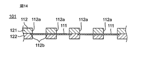
- FIG. 14 is a sectional view taken along line C1-C1 of FIG.
- the filtration filter 201 is clogged when the plurality of through-holes 201 a provided in the filtration filter 201 are all blocked by the filtration object 202.
- the filtration target 202 is a biological substance
- the deformability of the biological substance is high, and therefore the filtration target 202 is easily deformed into a flat shape during filtration as shown in FIG. That is, the biological substance is substantially spherical in the liquid, but is flattened by being rapidly decelerated by the main surface of the filtration filter 201 perpendicular to the fluid flow direction during filtration and pressed against the main surface. It is easy to deform.
- one filtering object 202 deformed into a flat shape closes the plurality of through holes 201a, and clogging is more likely to occur.
- the filtration filter 201 since the filtration filter 201 is attached so that a tensile force is applied from the central portion toward the outer peripheral portion, the filtration filter 201 takes a flat posture without bending.
- the present inventors filtered the same amount of filtration object 202 through the filtration filter 201 in a state where the filtration filter 201 is bent toward the side not receiving the pressure of the liquid. It was found that the through-hole 201a in the outer peripheral portion of the filtration filter 201 is not blocked in the case where it is made. Further, the present inventors have slowed down the flow velocity of the filtration target object 202 slowly by the curved surface of the filtration filter 201, so that the filtration target object 202 is in a flat shape close to a substantially spherical shape in the liquid. 201 was found to be captured.
- the present inventors when the filtration filter 201 filters the same amount of the filtration object 202 with the filtration filter 201 bent toward the liquid pressure receiving side. Found that the through-hole 201a at the center of the filter 201 was not blocked. That is, the present inventors increase the amount of filtration object necessary to close all the through holes 201a by performing filtration in a state where the filtration filter 201 is positively (forced) bent, It has been found that the filtration throughput can be increased. Based on this novel finding, the present inventors have reached the following invention.
- the filtration device is A filtration filter comprising a membrane part for filtering an object to be filtered contained in a fluid, and a frame part for holding the membrane part; A filter holding part for holding the frame part so that the film part bends; A fluid supply section for supplying the fluid in a state where the membrane section is bent; Is provided.
- the bending amount of the film part due to the filter holding part holding the frame part is larger than the bending amount of the film part due to the pressure of the fluid. That is, it is preferable that the film part is positively bent. According to this configuration, it is possible to further increase the amount of filtration processing by further suppressing clogging of the filtration filter.
- the filter holding part may hold the frame part so that the film part bends toward the side receiving the pressure of the fluid. According to this configuration, it is possible to increase the amount of filtration processing while suppressing clogging of the filtration filter.
- the filter holding part may have a mechanism for changing an inclination angle of the frame part with respect to a horizontal plane.
- the membrane portion can be bent when filtering, while the membrane portion can be prevented from bending when not filtering. In this case, it is possible to suppress the load on the film part by bending the film part.
- the membrane part may be a metal thin film having a plurality of through holes that separate biological substances from the fluid.
- the filtration device is A filtration filter group comprising: a membrane part for filtering an object to be filtered contained in a fluid; and a holder provided with a plurality of through holes for holding the membrane part and exposing the membrane part at a plurality of locations; , A filter holding part for holding the holding body so that the film part bends; A fluid supply section for supplying the fluid in a state where the membrane section is bent; A transport device that transports at least one of the filtration filter group and the fluid supply unit so that the fluid from the fluid supply unit is supplied to the membrane unit; Is provided.
- the transport device may have a mechanism for transporting at least one of the filtration filter group and the fluid supply unit so that the film unit to which the fluid supply unit supplies the fluid is sequentially changed. According to this configuration, the filtration filter can be easily replaced.
- the amount of bending of the film portion due to the filter holding portion holding the holding body is larger than the amount of bending of the film portion due to the pressure of the fluid. That is, it is preferable that the film part is positively bent. According to this configuration, it is possible to further increase the amount of filtration processing by further suppressing clogging of the filtration filter.
- the filter holding part may have a mechanism for changing an inclination angle of the holding body with respect to a horizontal plane.
- the membrane can be bent when filtering, while the membrane can be prevented from bending when not filtered. In this case, it is possible to suppress the load on the film part by bending the film part.
- the membrane part may be a metal thin film having a plurality of through holes that separate biological substances from the fluid.
- the holding body may be a tape-like member having flexibility, and the plurality of through holes may be provided along a longitudinal direction of the holding body. According to this configuration, the filtration filter group can be wound and stored in a small size, or can be deformed into an arbitrary shape, so that the handleability can be further improved.
- the filter holding unit may have a mechanism for deforming the holding body into a wave shape toward the carrying direction by the carrying device. According to this structure, each film
- a filtration method includes: A step of preparing a membrane part for filtering an object to be filtered contained in a fluid; Supplying the fluid in a state where the membrane portion is bent; including.
- This method can increase the amount of filtration processing while suppressing clogging of the filtration filter.
- the method may further include a step of reducing the amount of bending of the film part after supplying the fluid. According to this method, when collection
- a filtration filter comprising a membrane part for filtering an object to be filtered contained in a fluid, and a frame part for holding the membrane part, The film part is held by the frame part so as to maintain a bent state.
- the bending amount of the film part is preferably larger than the bending amount of the film part due to the pressure of the fluid. That is, it is preferable that the film part is positively bent. According to this configuration, it is possible to further increase the amount of filtration processing by further suppressing clogging of the filtration filter.
- FIG. 1 is a plan view showing a schematic configuration of a filtration filter used in the filtration device according to Embodiment 1 of the present invention.
- 2 is a cross-sectional view taken along line A1-A1 of FIG.
- the filtration object is a biological substance contained in the liquid.
- the “biological substance” means a substance derived from a living organism such as a cell (eukaryotic organism), a bacterium (eubacteria), or a virus.
- cells eukaryotes
- examples of cells include eggs, sperm, induced pluripotent stem cells (iPS cells), ES cells, stem cells, mesenchymal stem cells, mononuclear cells, single cells, cell masses, suspension cells, and adhesions.
- sex cells nerve cells, leukocytes, lymphocytes, cells for regenerative medicine, autologous cells, cancer cells, circulating cancer cells (CTC), HL-60, HELA, and fungi.
- bacteria examples include gram positive bacteria, gram negative bacteria, Escherichia coli, and tuberculosis bacteria.
- virus examples include DNA virus, RNA virus, rotavirus, (bird) influenza virus, yellow fever virus, dengue fever virus, encephalitis virus, hemorrhagic fever virus, and immunodeficiency virus.
- the filtration filter 1 includes a membrane portion 11 and a frame portion 12 that holds the membrane portion 11.
- the film part 11 is composed of a circular metal thin film.
- the material of the film part 11 include gold, silver, copper, platinum, nickel, stainless steel, palladium, titanium, cobalt, and alloys thereof.
- the material of the film part 11 is more preferably a material that can be sterilized in various ways such as gamma irradiation, autoclave, and ethylene gas.
- the film part 11 may be a resin thin film, filter paper, or the like. That is, the film part 11 should just be a porous film.
- the dimensions of the film part 11 are, for example, a diameter of 8 mm and a thickness of 1.2 ⁇ m.
- it is 100 nm or more and 100 micrometers or less, and, as for the thickness of the film part 11, it is more preferable that it is 500 nm or more and 30 micrometers or less so that it may have moderate flexibility.
- the film part 11 has a pair of main surfaces facing each other, and has a plurality of through holes 11a penetrating both main surfaces.
- the through hole 11a separates a biological substance from the liquid.
- the shape and size of the through-hole 11a are appropriately set according to the shape and size of the biological material.
- the through holes 11a are, for example, arranged at regular intervals or periodically.
- the shape of the through hole 11a is, for example, a square when viewed from the main surface side of the film part 11.
- the size of the through hole 11a is, for example, from 0.1 ⁇ m to 500 ⁇ m in length and from 0.1 ⁇ m to 500 ⁇ m in width.
- the interval between the through holes 11a is, for example, greater than 1 time and less than 10 times, more preferably less than 3 times the opening diameter of the through holes 11a.
- membrane part 11 is 10% or more, for example.
- the frame portion 12 is made of a flexible member.
- the material of the frame portion 12 include polypropylene, polyester, polyurethane, rayon, polyvinyl chloride, hydrogel, nylon, polyolefin, and paper.
- the material of the frame portion 12 is more preferably a material that can be sterilized in various ways, such as gamma irradiation, autoclave, and ethylene gas. Examples of such a material include polyester, polyurethane, and polyvinyl chloride.
- the width of the frame portion 12 is, for example, 3.9 mm.
- the thickness of the frame portion 12 is, for example, 3.0 mm.
- the frame portion 12 has a two-layer structure, and includes a first layered member 21 and a second layered member 22.
- the first layered member 21 is connected to one main surface of the film part 11 by, for example, an adhesive.
- the second layered member 22 is connected to the other main surface of the film part 11 by, for example, an adhesive. That is, the frame part 12 is connected to both one main surface and the other main surface of the film part 11. Thereby, when the filter 1 is bent, it can suppress that the film
- the first layered member 21 and the second layered member 22 are connected to each other by, for example, an adhesive.
- the said adhesive agent is a water-insoluble adhesive agent. Examples of such an adhesive include an epoxy adhesive and a silylated urethane resin adhesive.
- the frame portion 12 is formed in an annular shape.
- a concave portion 12 b is provided on the inner peripheral wall of the frame portion 12.
- the recess 12b is formed in an annular shape, for example.
- the film part 11 is held by the frame part 12 by fitting the outer peripheral part into the concave part 12b. By providing the recess 12b, for example, the positional deviation of the film part 11 can be suppressed.
- the concave portion 12b may be provided in at least one of the first layered member 21 and the second layered member 22.
- FIG. 3 is a cross-sectional view illustrating a schematic configuration of the filtration device 2.
- FIG. 4 is a cross-sectional view showing a state in which the membrane unit 11 is bent in the filtration device 2. The operation of the filtration device 2 is controlled by a control unit provided in the filtration device 2 based on a program stored in advance.
- the filtration device 2 includes a filter holding unit 3 that holds the frame portion 12, and a fluid supply unit 4 that supplies a liquid containing a biological substance BP to the membrane unit 11.
- the filter holding unit 3 is configured to hold the frame unit 12 so that the membrane unit 11 bends with respect to a plane P1 intersecting (for example, orthogonal to) the fluid supply direction. ing.
- the fluid supply unit 4 supplies the liquid containing the biological substance BP to the film unit 11 in a state where the film unit 11 is bent. Thereby, the membrane part 11 filters the biological substance BP in the liquid.
- the fluid supply unit supplies the liquid containing the biological substance BP while the filter holding unit 3 is bending the film unit 11, the entire penetration of the film unit 11 is performed. It is possible to increase the amount of the biological substance BP necessary for closing the hole 11a. Thereby, it is possible to suppress clogging of the filtration filter 1 by preventing the through-hole 11a at the peripheral edge of the membrane part 11 from being blocked by the biological substance BP. As a result, the amount of filtration processing of the filtration filter 1 can be increased as compared with the prior art.
- “bending” does not mean only bending in an arc shape. For example, “bending” includes bending (bending) an acute angle, a right angle, or an obtuse angle.
- maintaining the frame part 12 is larger than the bending amount of the film
- the filter holding unit 3 has a frame part so that the bending amount L1 in the exposed part of the film part 11 not held by the frame part 12 is twice or more the average particle diameter of the biological substance BP. 12 is preferably retained. According to this configuration, clogging of the filtration filter 1 can be further suppressed, and the amount of filtration processing can be further increased.
- the “bending amount” is the distance from the plane P1 passing through the outer peripheral end of the exposed part of the film part 11 (the connection part between the frame part 12 and the film part 11) to the plane P2 passing through the bottom of the film part 11.
- the plane P1 and the plane P2 are parallel to each other.
- the average particle diameter of the biological substance BP is, for example, 10 ⁇ m.
- maintains the frame part 12 so that the volume of the bending part of the film
- the filter holding part 3 should just hold
- the filter holding unit 3 may hold the frame unit 12 in a fixed manner so as to always maintain the bent state of the film unit 11.
- maintenance part 3 may be comprised so that it may have a mechanism which changes the inclination angle of the frame part 12 with respect to a horizontal surface (for example, 0 degree or more and 30 degrees or less). According to this configuration, for example, the membrane portion 11 can be bent when filtering, while the membrane portion 11 can be prevented from bending when not filtering.
- membrane part 11 can be decreased.
- the bending amount L1 of the film part 11 can be reduced.
- the filter holding part 3 is configured to hold the frame part 12 so that the film part 11 bends toward the side not receiving the liquid pressure.
- the filter holding unit 3 may be configured to hold the frame unit 12 so that the film unit 11 bends toward the side receiving the liquid pressure.
- a container 13 having a through hole for allowing the membrane portion 11 to enter the bottom surface is arranged so that the liquid supplied from the fluid supply portion 4 does not flow to a portion other than the membrane portion 11. May be.
- the filtering target is the biological material BP contained in the liquid, but the present invention is not limited to this.
- a large foreign substance contained in the liquid may be used as the filtering object.
- the filtering object may be a substance contained in a gas. That is, the filtration object may be a substance contained in the fluid, and may be, for example, PM2.5 contained in the air.
- the filtration filter 1 and the filtration device 2 are used for filtering the biological substance BP from the liquid, but the present invention is not limited to this.
- the filtration filter 1 and the filtration device 2 may be used, for example, to concentrate components contained in a liquid.
- the frame portion 12 is configured to be connected to both main surfaces of the film portion 11, but the present invention is not limited to this. As shown in FIG. 6, the frame part 12 may be connected only to one main surface of the film part 11. In this case, since it is not necessary to provide the second layered member 22 on the other main surface of the film part 11, the cost can be reduced. Moreover, since the flexibility of the frame part 12 can be improved, for example, the frame part 12 can be prevented from being damaged when the frame part 12 is bent.
- FIG. 7 is a plan view showing a schematic configuration of a filtration filter group used in the filtration device according to Embodiment 2 of the present invention.
- 8 is a cross-sectional view taken along line B1-B1 of FIG. 9 is a cross-sectional view taken along line B2-B2 of FIG.
- the filtering object is a biological substance contained in the liquid.
- the filtering object may be PM2.5 contained in the gas.
- the filtration filter group 101 includes a plurality of film portions 111 and a holding body 112 that holds the plurality of film portions 111.
- the film unit 111 is the same as the film unit 11 described above, and thus detailed description thereof is omitted.
- the holding body 112 is a flexible tape-like member.
- the holding body 112 is provided with a plurality of through holes 112a.
- the plurality of through holes 112a are provided at equal intervals along the longitudinal direction of the holding body 112, for example.
- the shape and dimensions of the through hole 112a are appropriately set according to the desired amount of filtration treatment, filtration treatment time, and the like.
- the shape of the through hole 112a is, for example, circular when viewed from the main surface side of the holding body 112.
- the size of the through hole 112a is, for example, 6 mm in diameter.
- the interval between the through holes 112a is, for example, 12 mm.
- the holding body 112 is composed of a flexible member.
- the material of the holding body 112 include polypropylene, polyester, polyurethane, rayon, polyvinyl chloride, hydrogel, nylon, polyolefin, and paper.
- the material of the holding body 112 is more preferably a material that can be sterilized in various ways such as gamma irradiation, autoclave, and ethylene gas. Examples of such a material include polyester, polyurethane, and polyvinyl chloride.
- the width of the holding body 112 is 12 mm, for example.
- the thickness of the holding body 112 is, for example, 500 ⁇ m.
- the holding body 112 has a two-layer structure, and includes a first layered member 121 and a second layered member 122.
- the first layered member 121 is connected to one main surface of the film unit 111 by, for example, an adhesive.
- the second layered member 122 is connected to the other main surface of the film part 111 by, for example, an adhesive. That is, the holding body 112 is connected to both one main surface and the other main surface of the film part 11. Thereby, when the filter group 101 is bent, it is possible to prevent the film part 111 from being peeled off from the holding body 112.
- the first layered member 121 and the second layered member 122 are connected to each other by an adhesive, for example.
- the said adhesive agent is a water-insoluble adhesive agent. Examples of such an adhesive include an epoxy adhesive and a silylated urethane resin adhesive.
- the wall surface of the holding body 112 that forms each through hole 112a is provided with a recess 112b.
- the recess 112b is formed in an annular shape, for example.
- the film part 111 is held by the holding body 112 by fitting the outer peripheral part into the recess 112b. Thereby, the film
- the recess 112b may be provided in at least one of the first layered member 121 and the second layered member 122.
- FIG. 10 is a side view showing a schematic configuration of the filtration device 102.
- the filtration device 102 includes a transport device 103, two filter holding units 104 and 104, and a fluid supply unit 105.
- the transport device 103 transports the filtration filter group 101 so that the film part 111 exposed from the specific through hole 112a is located in the fluid supply region E1 between the two filter holding parts 104 and 104. Moreover, the conveying apparatus 103 conveys the filtration filter group 101 so that the film
- the transport device 103 includes a supply reel 131 and a take-up reel 132.
- a filtration filter group 101 is wound around the supply reel 131. Further, the supply reel 131 is provided with a feeding motor 131a. The filter group 101 is fed out from the supply reel 131 by driving the feeding motor 131a. The filter group 101 fed out from the supply reel 131 is taken up by the take-up reel 132.
- the take-up reel 132 is provided with a take-up motor 132a. For example, a certain tension is applied to the take-up reel 132 by driving the take-up motor 132a. Thereby, the filter group 101 fed out from the supply reel 131 is taken up on the take-up reel 132 simultaneously with the feeding out.
- the two filter holders 104 and 104 are disposed between the supply reel 131 and the take-up reel 132. More specifically, one filter holding unit 104 is arranged on the upstream side in the transport direction of the filtration filter group 101 with respect to the fluid supply region E1. The other filter holding part 104 is arrange
- Each filter holding portion 104, 104 is composed of a pair of guide rollers 104a, 104b. The filtration filter group 101 is nipped and conveyed between the guide roller 104a and the guide roller 104b so as to bend in the fluid supply region E1.
- each filter holding unit 104 is configured to have a mechanism for changing the inclination angle of the holding body 112 with respect to the horizontal plane (for example, 0 ° or more and 30 ° or less).
- each filter holding unit 104 is configured to bend the film part 111 when filtering, while not bending the film part 111 when not filtering.
- the fluid supply unit 105 is provided to supply a liquid containing a biological substance to the membrane unit 111 exposed from the specific through hole 112a of the filtration filter group 101 bent by the filter holding unit 104 in the fluid supply region E1. It has been.
- the operation of the filtration device 102 is controlled based on a program stored in advance by a control unit (not shown) provided in the filtration device 102.
- the filter holding unit 104 holds the holding body 112 so as to bend the membrane unit 111 with respect to a plane that intersects (for example, orthogonally intersects) the fluid supply direction.
- the fluid supply unit 105 supplies a liquid containing a biological substance to the film unit 111 bent by the filter holding unit 104.
- the supply of the liquid containing the biological substance is continued for a certain time, for example, a time when the film unit 111 is assumed to be clogged.
- the filter holding unit 104 is released from holding the holding body 112 so as to bend the film unit 111.
- the membrane portion 111 that performs the next filtration enters the fluid supply region E1. Be transported. Thereby, the film
- the film holding section 104 is bent by the filter holding section 104 in the same manner, and the fluid supply section 105 supplies the liquid to the bent film section 111. . Further, replacement of the film unit 111 located in the fluid supply region E ⁇ b> 1 is performed by the transfer device 103.
- the fluid supply unit 105 supplies the liquid containing the biological substance while the filter holding unit 104 is bending the film unit 111, the entire penetration of the film unit 111 is performed. It is possible to increase the amount of biological material necessary to close the hole 111a. Thereby, it can suppress that the through-hole 111a of the peripheral part of the film
- “bending” does not mean only bending in an arc as described above. For example, “bending” includes bending (bending) an acute angle, a right angle, or an obtuse angle.
- the transport device 103 transports the filtration filter group 101 so that the film unit 111 positioned in the fluid supply region E1 is sequentially changed, so that the film unit 111 can be easily replaced. Can be done.
- the filter can be easily replaced. Moreover, foreign matter contamination (contamination) can be reduced by exchanging the filtration filter.
- the filter holding unit 104 is configured to have a mechanism for changing the inclination angle of the holding body 112 with respect to the horizontal plane.
- the membrane portion 111 can be bent when filtering, while the membrane portion 111 can be prevented from bending when not filtering. In this case, it is possible to suppress the load on the film unit 111 by bending the film unit 111.
- membrane part 111 can be decreased. In this case, when collecting or analyzing a biological substance after completion of filtration, it can be performed in a state where the bending amount of the membrane part 111 is reduced.
- the holding body 112 is a flexible tape-like member
- the filtration filter group 101 can be wound and stored in a small size, or can be deformed into an arbitrary shape. , Improve convenience.
- a plurality of film portions 111 are provided so as to correspond to the plurality of through holes 112a. That is, one film portion 111 is provided in one through hole 112a. As a result, it is possible to reduce the area where the film part 111 is provided rather than providing the film part 111 with the same area as the holding body 112, and to reduce the cost.
- maintaining the holding body 112 is larger than the bending amount of the film
- the filter holding unit 104 preferably holds the holding body 112 so that the amount of bending at the exposed portion of the film part 111 that is not held by the holding body 112 is twice or more the average particle diameter of the biological substance. According to this configuration, it is possible to further increase the amount of filtration processing by further suppressing clogging of the filtration filter. Note that the amount of bending at the exposed portion of the film portion 111 is the same as the amount of bending at the exposed portion of the film portion 11 described above with reference to FIG.
- the volume of the bent portion of the film part 111 defined by the surface of the film part 111 and the plane passing through the outer peripheral end of the exposed part of the film part 111 is equal to or greater than the total volume of the filtration object.
- the filter holding unit 104 is configured so that the filtration filter group 101 is bent in the longitudinal direction (part of the conveyance direction X by the conveyance device 103).
- the invention is not limited to this, for example, as shown in Fig. 11, the two filter holding units 104 may be configured so that the filter group 101 is bent in the short direction, and as shown in Fig. 12,
- the filter holding unit 104 may be configured such that the filter group 101 (holding body 112) is deformed in a wave shape toward the conveyance direction by the conveyance device 103.
- Adjacent filter holders 104 and 104 may be configured to share a single guide roller 104. According to these configurations, each film held by the holding body 112 is used.
- the plurality of membrane portions 111 can be bent at the same time, by supplying a liquid containing a biological substance from the plurality of fluid supply portions 105 to the plurality of membrane portions 111 at the same time, It is possible to increase the amount of filtration processing and shorten the filtration time.
- one film portion 111 is provided in one through hole 112a.
- the present invention is not limited to this.
- the membrane portion 111 may be formed in a size including two or more through holes 112 a when viewed from the thickness direction of the filtration filter group 101. That is, one film portion 111 may be formed so as to be exposed from two or more through holes 112a.
- the holding body 112 is configured to be connected to both main surfaces of the film unit 111, but the present invention is not limited to this.
- the holding body 112 may be connected only to one main surface of the film part 111 as shown in FIG. In this case, since it is not necessary to provide the second layered member 122 on the other main surface of the film part 111, the cost can be reduced.
- the flexibility of the holding body 112 can be improved, for example, it is possible to prevent the holding body 112 from being damaged when the holding body 112 is bent.
- the transport device 103 transports the filtration filter group 101 to transport the membrane unit 111 to the fluid supply region E1, but the present invention is not limited to this.
- the transfer device 103 may be configured to transfer the film unit 111 to the fluid supply region E1 by transferring at least one of the filtration filter group 101 and the fluid supply unit 105.
- the holding body 112 may be provided with a cutoff line 112c between the adjacent through holes 112a and 12a. According to this configuration, it is possible to obtain the filtration filter group 101 having a desired length by cutting along the cutoff line 112c, and it is possible to further improve the handleability of the filtration filter group 101. For example, it becomes possible to cut a part of the holding body 112 including the membrane part 111 obtained by filtering the biological material by the cutting line 112c and analyze it with a microscope or the like.
- the holding body 112 may be provided with a plurality of feed holes 113 as shown in FIG.
- the plurality of feed holes 113 may be provided at regular intervals along the longitudinal direction of the holding body 112, for example.
- the conveying device 103 may be configured to include a wheel (not shown) including a plurality of pins corresponding to the plurality of feed holes 113.
- the protective sheet 114 may be provided on the outermost peripheral surface of the roll body 106 in which the holding body 112 (filter filter group 101) is wound in a roll shape. Further, a protective sheet (not shown) may be provided on at least one of the pair of bottom surfaces 106A and 106B facing each other of the roll body 106. According to this configuration, it is possible to prevent dirt and damage to the filtration filter group, and it is possible to further improve the handleability.
- protective sheets 115 that cover the film portions 111 exposed at a plurality of locations may be provided on both main surfaces of the holding body 112. According to this configuration, it is possible to prevent the filtration filter group 101 from being soiled or damaged, and the handling property can be further improved.
- the protective sheet 15 may be provided only on one main surface of the holding body 112. According to this configuration, the flexibility of the holding body 112 can be improved.
- each protective sheet with the member which has flexibility, such as a polystyrene, polyethylene, polyester, a polyurethane, rayon, PVC, a hydrogel, nylon, polyolefin, a cellulose, for example.
- the material of each protective sheet is more preferably a material that can be sterilized in various ways, such as gamma irradiation, autoclave, and ethylene gas. Examples of such a material include polyester, polyurethane, and polyvinyl chloride.
- FIG. 19 is a cross-sectional view showing a schematic configuration of a filtration filter used in the filtration device according to Embodiment 3 of the present invention.
- the difference between the filter 1A according to the third embodiment and the filter 1 according to the first embodiment is that the membrane portion 11 is held by the frame portion 12 so as to maintain a bent state. . That is, in the third embodiment, the film part 11 is not forcibly bent by the filter holding part 3 but is held by the frame part 12 in a bent state in advance.
- the membrane portion 11 is held by the frame portion 12 so as to maintain the bent state, the biological material necessary for closing all the through holes 11a of the membrane portion 11 The amount of BP can be increased. Thereby, clogging of the filter 1A can be suppressed, and the amount of filtration processing can be increased. Further, according to the third embodiment, it is possible to eliminate the necessity of providing the filter holding unit 3 described above with reference to FIGS.
- the bending amount of the film part 11 is larger than the bending amount of the film part 11 by the pressure of the fluid.
- the bending amount L2 in the exposed part of the film part 11 that is not held by the frame part 12 is preferably at least twice the average particle diameter of the object to be filtered, as shown in FIG.
- the membrane portion 11 is arranged such that the volume of the bent portion of the membrane portion 11 defined by the surface of the membrane portion 11 and the plane passing through the outer peripheral end of the exposed portion of the membrane portion 11 is equal to or greater than the total volume of the filtration object. It is preferable to be held by the frame portion 12.
- FIG. 20 is a cross-sectional view showing a schematic configuration of a filtration filter group used in the filtration device according to Embodiment 4 of the present invention.
- the difference between the filter group 101A according to the fourth embodiment and the filter group 101 according to the second embodiment is that the membrane portion 111 is held by the holding body 112 so as to maintain a bent state. It is. That is, in the fourth embodiment, the film unit 111 is not forcibly bent by the filter holding unit 104 but is held by the holding body 112 in a bent state.
- the membrane portion 111 is held by the holding body 112 so as to maintain the bent state, the biological substance necessary for closing all the through holes 111a of the membrane portion 111.
- the amount of BP can be increased. Thereby, clogging of filtration filter group 101A can be suppressed, and the amount of filtration processing can be increased. Further, according to the fourth embodiment, it is possible to eliminate the necessity of providing the filter holding unit 104 described above with reference to FIGS.
- the bending amount of the film part 111 is preferably larger than the bending amount of the film part 111 due to the pressure of the fluid.
- the bending amount in the exposed part of the film part 111 that is not held by the holding body 112 is preferably at least twice the average particle diameter of the object to be filtered.
- the membrane portion 111 is configured such that the volume of the bent portion of the membrane portion 111 defined by the surface of the membrane portion 111 and the plane passing through the outer peripheral end of the exposed portion of the membrane portion 111 is equal to or greater than the total volume of the object to be filtered. It is preferable to be held by the holding body 112. These configurations can further increase the amount of filtration processing by further suppressing clogging of the filtration filter.
- the present invention can increase the amount of filtration processing by suppressing clogging of the filtration filter, and thus is useful for a filtration apparatus and a filtration method for filtering an object to be filtered contained in a fluid such as a biological material or PM2.5. is there.
Abstract
The present invention provides a filtration device in which the filtration treatment amount can be increased by suppressing clogging of a filtration filter. A filtration device according to the present invention includes: a filtration filter (1) including a membrane part (11) that filters an object to be filtered, which is contained in a fluid, and frame parts (12) that retain the membrane part (11); filter-retaining parts (3) that retain the frame parts (12) in such a manner that the membrane part (11) is bent; and a fluid-supply part (4) that supplies fluid in a state in which the membrane part (11) is bent.
Description
本発明は、流体に含まれる濾過対象物を濾過する濾過装置、濾過方法、及び濾過フィルタに関する。
The present invention relates to a filtration device, a filtration method, and a filtration filter for filtering an object to be filtered contained in a fluid.
従来、流体に含まれる濾過対象物を濾過する濾過フィルタとして、例えば、特許文献1(国際公開公報第2015/019889号)に開示されたものが知られている。
Conventionally, for example, a filter disclosed in Patent Document 1 (International Publication No. 2015/019889) is known as a filter for filtering an object to be filtered contained in a fluid.
特許文献1には、液体に含まれる生物由来物質を濾過する濾過フィルタが開示されている。この濾過フィルタは、中央部から外周部に向かって引張力が掛かるように、外周部が蓋部材と収納部材との間に嵌合するように取り付けられる。この状態で、濾過フィルタに生物由来物質を含む液体を通過させることで、生物由来物質を濾過する。
Patent Document 1 discloses a filtration filter for filtering a biological substance contained in a liquid. The filtration filter is attached so that the outer peripheral portion is fitted between the lid member and the storage member so that a tensile force is applied from the central portion toward the outer peripheral portion. In this state, the biological material is filtered by passing a liquid containing the biological material through the filter.
濾過フィルタは、生物由来物質などの濾過対象物の濾過が進むことで、目詰まりを生じる。濾過フィルタが目詰まりすると、濾過対象物の濾過を継続することができなくなる。
The filtration filter is clogged by the filtration of the filtration object such as a biological substance. If the filter is clogged, it will not be possible to continue filtering the object to be filtered.
本発明の目的は、前記課題を解決することにあって、濾過フィルタの目詰まりを抑えて濾過処理量を増大させることができる濾過装置、濾過方法、及び濾過フィルタを提供することにある。
An object of the present invention is to solve the above-described problems, and to provide a filtration device, a filtration method, and a filtration filter capable of increasing the amount of filtration processing while suppressing clogging of the filtration filter.
前記目的を達成するために、本発明の一態様に係る濾過装置は、
流体に含まれる濾過対象物を濾過する膜部と、前記膜部を保持する枠部とを備える濾過フィルタと、
前記膜部が曲がるように前記枠部を保持するフィルタ保持部と、
前記膜部が曲がった状態で前記流体を供給する流体供給部と、
を備える。 In order to achieve the above object, a filtration device according to an aspect of the present invention includes:
A filtration filter comprising a membrane part for filtering an object to be filtered contained in a fluid, and a frame part for holding the membrane part;
A filter holding part for holding the frame part so that the film part bends;
A fluid supply section for supplying the fluid in a state where the membrane section is bent;
Is provided.
また、本発明の一態様に係る濾過装置は、
流体に含まれる濾過対象物を濾過する膜部と、前記膜部を保持するとともに前記膜部を複数箇所で露出させるための複数の貫通穴が設けられている保持体とを備える濾過フィルタ群と、
前記膜部が曲がるように前記保持体を保持するフィルタ保持部と、
前記膜部が曲がった状態で前記流体を供給する流体供給部と、
前記膜部に前記流体供給部からの流体が供給されるように前記濾過フィルタ群及び前記流体供給部の少なくとも一方を搬送する搬送装置と、
を備える。 In addition, the filtration device according to one embodiment of the present invention includes:
A filtration filter group comprising: a membrane part for filtering an object to be filtered contained in a fluid; and a holder provided with a plurality of through holes for holding the membrane part and exposing the membrane part at a plurality of locations; ,
A filter holding part for holding the holding body so that the film part bends;
A fluid supply section for supplying the fluid in a state where the membrane section is bent;
A transport device that transports at least one of the filtration filter group and the fluid supply unit so that the fluid from the fluid supply unit is supplied to the membrane unit;
Is provided.
なお、この濾過装置においては、「濾過フィルタ」は、1つの貫通穴から露出する膜部と、その周囲に位置する保持体の一部とで構成されるものとする。また、この「濾過フィルタ」が複数連結され、一体化されたものを「濾過フィルタ群」という。
In this filtration apparatus, the “filtration filter” is composed of a membrane portion exposed from one through hole and a part of a holding body located around the membrane portion. A plurality of “filtration filters” connected together and integrated are referred to as a “filtration filter group”.
また、本発明の一態様に係る濾過方法は、
流体に含まれる濾過対象物を濾過する膜部を用意する工程と、
前記膜部を曲げた状態で前記流体を供給する工程と、
を含む。 The filtration method according to one embodiment of the present invention includes:
A step of preparing a membrane part for filtering an object to be filtered contained in a fluid;
Supplying the fluid in a state where the membrane portion is bent;
including.
また、本発明の一態様に係る濾過フィルタは、
流体に含まれる濾過対象物を濾過する膜部と、前記膜部を保持する枠部とを備える濾過フィルタであって、
前記膜部は、曲がった状態を維持するように前記枠部に保持されている。 Further, the filtration filter according to one embodiment of the present invention,
A filtration filter comprising a membrane part for filtering an object to be filtered contained in a fluid, and a frame part for holding the membrane part,
The film part is held by the frame part so as to maintain a bent state.
本発明によれば、濾過フィルタの目詰まりを抑えて濾過処理量を増大させることができる。
According to the present invention, it is possible to increase the amount of filtration processing while suppressing clogging of the filtration filter.
(本発明の基礎となった知見)
本発明者らは、従来の濾過装置においてより濾過処理量を増大させるために鋭意検討した結果、以下の知見を得た。 (Knowledge that became the basis of the present invention)
As a result of intensive studies to increase the amount of filtration treatment in the conventional filtration device, the present inventors have obtained the following knowledge.
本発明者らは、従来の濾過装置においてより濾過処理量を増大させるために鋭意検討した結果、以下の知見を得た。 (Knowledge that became the basis of the present invention)
As a result of intensive studies to increase the amount of filtration treatment in the conventional filtration device, the present inventors have obtained the following knowledge.
図21に示すように、濾過フィルタ201は、濾過フィルタ201に設けられた複数の貫通孔201aが全て濾過対象物202に塞がれることにより、目詰まりが生じる。特に濾過対象物202が生物由来物質である場合、生物由来物質の変形能が高いため、濾過対象物202は、図22に示すように、濾過時に扁平形状に変形しやすい。すなわち、生物由来物質は、液体中では略球形であるが、濾過時に流体の流れ方向に対して垂直な濾過フィルタ201の主面によって急激に減速されて当該主面に押し付けられることによって、扁平形状に変形しやすい。この場合、扁平形状に変形した1つの濾過対象物202が複数の貫通孔201aを塞ぐことになり、目詰まりが一層生じやすくなる。
As shown in FIG. 21, the filtration filter 201 is clogged when the plurality of through-holes 201 a provided in the filtration filter 201 are all blocked by the filtration object 202. In particular, when the filtration target 202 is a biological substance, the deformability of the biological substance is high, and therefore the filtration target 202 is easily deformed into a flat shape during filtration as shown in FIG. That is, the biological substance is substantially spherical in the liquid, but is flattened by being rapidly decelerated by the main surface of the filtration filter 201 perpendicular to the fluid flow direction during filtration and pressed against the main surface. It is easy to deform. In this case, one filtering object 202 deformed into a flat shape closes the plurality of through holes 201a, and clogging is more likely to occur.
従来の濾過装置においては、濾過フィルタ201が中央部から外周部に向かって引張力が掛かるように取り付けられるため、濾過フィルタ201は、曲がることなく、平坦な姿勢を取る。
In the conventional filtration device, since the filtration filter 201 is attached so that a tensile force is applied from the central portion toward the outer peripheral portion, the filtration filter 201 takes a flat posture without bending.
これに対して、本発明者らは、図23に示すように、濾過フィルタ201が液体の圧力を受けない側に向けて曲げた状態で、同量の濾過対象物202を濾過フィルタ201に濾過させた場合には、濾過フィルタ201の外周部の貫通孔201aが塞がれないことを見出した。また、本発明者らは、濾過対象物202の流れる速度が濾過フィルタ201の曲面によってゆっくりと減速されるため、濾過対象物202が、液体中での略球形に近い扁平形状の状態で濾過フィルタ201に捕捉されることを見出した。この場合、1つの濾過対象物202が複数の貫通孔201aを塞ぐことを抑えることができる。更に、本発明者らは、図24に示すように、濾過フィルタ201が液体の圧力を受ける側に向けて曲げた状態で、同量の濾過対象物202を濾過フィルタ201に濾過させた場合には、濾過フィルタ201の中央部の貫通孔201aが塞がれないことを見出した。すなわち、本発明者らは、濾過フィルタ201を積極的(強制的)に曲げた状態で濾過を行うことで、全部の貫通孔201aを閉塞するのに必要な濾過対象物の量が増加し、濾過処理量を増加させることができることを見出した。この新規な知見に基づき、本発明者らは以下の発明に至った。
On the other hand, as shown in FIG. 23, the present inventors filtered the same amount of filtration object 202 through the filtration filter 201 in a state where the filtration filter 201 is bent toward the side not receiving the pressure of the liquid. It was found that the through-hole 201a in the outer peripheral portion of the filtration filter 201 is not blocked in the case where it is made. Further, the present inventors have slowed down the flow velocity of the filtration target object 202 slowly by the curved surface of the filtration filter 201, so that the filtration target object 202 is in a flat shape close to a substantially spherical shape in the liquid. 201 was found to be captured. In this case, it can suppress that the one filtration target object 202 block | closes the several through-hole 201a. Furthermore, the present inventors, as shown in FIG. 24, when the filtration filter 201 filters the same amount of the filtration object 202 with the filtration filter 201 bent toward the liquid pressure receiving side. Found that the through-hole 201a at the center of the filter 201 was not blocked. That is, the present inventors increase the amount of filtration object necessary to close all the through holes 201a by performing filtration in a state where the filtration filter 201 is positively (forced) bent, It has been found that the filtration throughput can be increased. Based on this novel finding, the present inventors have reached the following invention.
本発明の一態様に係る濾過装置は、
流体に含まれる濾過対象物を濾過する膜部と、前記膜部を保持する枠部とを備える濾過フィルタと、
前記膜部が曲がるように前記枠部を保持するフィルタ保持部と、
前記膜部が曲がった状態で前記流体を供給する流体供給部と、
を備える。 The filtration device according to one embodiment of the present invention is
A filtration filter comprising a membrane part for filtering an object to be filtered contained in a fluid, and a frame part for holding the membrane part;
A filter holding part for holding the frame part so that the film part bends;
A fluid supply section for supplying the fluid in a state where the membrane section is bent;
Is provided.
この構成によれば、濾過フィルタの目詰まりを抑えて濾過処理量を増大させることができる。
According to this configuration, it is possible to increase the amount of filtration processing while suppressing clogging of the filtration filter.
なお、前記フィルタ保持部が前記枠部を保持することによる前記膜部の曲げ量は、前記流体の圧力による前記膜部の曲げ量よりも大きいことが好ましい。すなわち、膜部は、積極的に曲げられることが好ましい。この構成によれば、濾過フィルタの目詰まりを一層抑えて濾過処理量を一層増大させることができる。
In addition, it is preferable that the bending amount of the film part due to the filter holding part holding the frame part is larger than the bending amount of the film part due to the pressure of the fluid. That is, it is preferable that the film part is positively bent. According to this configuration, it is possible to further increase the amount of filtration processing by further suppressing clogging of the filtration filter.
また、前記フィルタ保持部は、前記膜部が前記流体の圧力を受ける側に向けて曲がるように前記枠部を保持してもよい。この構成によれば、濾過フィルタの目詰まりを抑えて濾過処理量を増大させることができる。
Further, the filter holding part may hold the frame part so that the film part bends toward the side receiving the pressure of the fluid. According to this configuration, it is possible to increase the amount of filtration processing while suppressing clogging of the filtration filter.
また、前記フィルタ保持部は、水平面に対する前記枠部の傾斜角度を変化させる機構を有してもよい。この構成によれば、例えば、濾過するときに膜部を曲げる一方で、濾過しないときには膜部を曲げないようにすることができる。この場合、膜部を曲げることにより膜部に負荷がかかることを抑えることができる。
Further, the filter holding part may have a mechanism for changing an inclination angle of the frame part with respect to a horizontal plane. According to this configuration, for example, the membrane portion can be bent when filtering, while the membrane portion can be prevented from bending when not filtering. In this case, it is possible to suppress the load on the film part by bending the film part.
また、前記膜部は、前記流体から生物由来物質を分離する複数の貫通孔を有する金属製薄膜であってもよい。
Further, the membrane part may be a metal thin film having a plurality of through holes that separate biological substances from the fluid.
本発明の一態様に係る濾過装置は、
流体に含まれる濾過対象物を濾過する膜部と、前記膜部を保持するとともに前記膜部を複数箇所で露出させるための複数の貫通穴が設けられている保持体とを備える濾過フィルタ群と、
前記膜部が曲がるように前記保持体を保持するフィルタ保持部と、
前記膜部が曲がった状態で前記流体を供給する流体供給部と、
前記膜部に前記流体供給部からの流体が供給されるように前記濾過フィルタ群及び前記流体供給部の少なくとも一方を搬送する搬送装置と、
を備える。 The filtration device according to one embodiment of the present invention is
A filtration filter group comprising: a membrane part for filtering an object to be filtered contained in a fluid; and a holder provided with a plurality of through holes for holding the membrane part and exposing the membrane part at a plurality of locations; ,
A filter holding part for holding the holding body so that the film part bends;
A fluid supply section for supplying the fluid in a state where the membrane section is bent;
A transport device that transports at least one of the filtration filter group and the fluid supply unit so that the fluid from the fluid supply unit is supplied to the membrane unit;
Is provided.
この構成によれば、濾過フィルタの目詰まりを抑えて濾過処理量を増大させることができる。
According to this configuration, it is possible to increase the amount of filtration processing while suppressing clogging of the filtration filter.
なお、前記搬送装置は、前記流体供給部が流体を供給する前記膜部が逐次変更されるように、前記濾過フィルタ群及び前記流体供給部の少なくとも一方を搬送する機構を有してもよい。この構成によれば、濾過フィルタの交換を容易に行うことができる。
Note that the transport device may have a mechanism for transporting at least one of the filtration filter group and the fluid supply unit so that the film unit to which the fluid supply unit supplies the fluid is sequentially changed. According to this configuration, the filtration filter can be easily replaced.
また、前記フィルタ保持部が前記保持体を保持することによる前記膜部の曲げ量は、前記流体の圧力による前記膜部の曲げ量よりも大きいことが好ましい。すなわち、膜部は、積極的に曲げられることが好ましい。この構成によれば、濾過フィルタの目詰まりを一層抑えて濾過処理量を一層増大させることができる。
In addition, it is preferable that the amount of bending of the film portion due to the filter holding portion holding the holding body is larger than the amount of bending of the film portion due to the pressure of the fluid. That is, it is preferable that the film part is positively bent. According to this configuration, it is possible to further increase the amount of filtration processing by further suppressing clogging of the filtration filter.
また、前記フィルタ保持部は、水平面に対する前記保持体の傾斜角度を変化させる機構を有してもよい。この構成によれば、例えば、濾過するときに膜部を曲げる一方、濾過しないときには膜部を曲げないようにすることができる。この場合、膜部を曲げることにより膜部に負荷がかかることを抑えることができる。
Further, the filter holding part may have a mechanism for changing an inclination angle of the holding body with respect to a horizontal plane. According to this configuration, for example, the membrane can be bent when filtering, while the membrane can be prevented from bending when not filtered. In this case, it is possible to suppress the load on the film part by bending the film part.
また、前記膜部は、前記流体から生物由来物質を分離する複数の貫通孔を有する金属製薄膜であってもよい。
Further, the membrane part may be a metal thin film having a plurality of through holes that separate biological substances from the fluid.
また、前記保持体は、可撓性を有するテープ状部材であり、前記複数の貫通穴は、前記保持体の長手方向に沿って設けられてもよい。この構成によれば、濾過フィルタ群を巻いて小型に収納したり、任意の形状に変形することができるので取扱い性をより向上させることができる。
Further, the holding body may be a tape-like member having flexibility, and the plurality of through holes may be provided along a longitudinal direction of the holding body. According to this configuration, the filtration filter group can be wound and stored in a small size, or can be deformed into an arbitrary shape, so that the handleability can be further improved.
また、前記フィルタ保持部は、前記保持体を前記搬送装置による搬送方向に向かって波型に変形させる機構を有してもよい。この構成によれば、保持体に保持される各膜部を容易に曲げることができる。
Further, the filter holding unit may have a mechanism for deforming the holding body into a wave shape toward the carrying direction by the carrying device. According to this structure, each film | membrane part hold | maintained at a holding body can be bent easily.
本発明の一態様に係る濾過方法は、
流体に含まれる濾過対象物を濾過する膜部を用意する工程と、
前記膜部を曲げた状態で前記流体を供給する工程と、
を含む。 A filtration method according to one embodiment of the present invention includes:
A step of preparing a membrane part for filtering an object to be filtered contained in a fluid;
Supplying the fluid in a state where the membrane portion is bent;
including.
この方法によれば、濾過フィルタの目詰まりを抑えて濾過処理量を増大させることができる。
This method can increase the amount of filtration processing while suppressing clogging of the filtration filter.
なお、前記流体を供給する前に前記膜部を曲げる工程を更に含んでもよい。この方法によれば、濾過しないときにおいて、膜部を曲げる必要性を無くすことができる。
In addition, you may further include the process of bending the said film | membrane part before supplying the said fluid. According to this method, it is possible to eliminate the need to bend the membrane part when not filtering.
また、前記流体を供給した後、前記膜部の曲げ量を減少させる工程を更に含んでもよい。この方法によれば、濾過終了後に濾過対象物の回収や分析等を行うときに、膜部の曲げ量を減少させた状態で行うことができる。
The method may further include a step of reducing the amount of bending of the film part after supplying the fluid. According to this method, when collection | recovery of a filtration target object, analysis, etc. are performed after completion | finish of filtration, it can carry out in the state which reduced the bending amount of the film | membrane part.
また、本発明の一態様に係る濾過フィルタは、
流体に含まれる濾過対象物を濾過する膜部と、前記膜部を保持する枠部とを備える濾過フィルタであって、
前記膜部は、曲がった状態を維持するように前記枠部に保持されている。 Further, the filtration filter according to one embodiment of the present invention,
A filtration filter comprising a membrane part for filtering an object to be filtered contained in a fluid, and a frame part for holding the membrane part,
The film part is held by the frame part so as to maintain a bent state.
流体に含まれる濾過対象物を濾過する膜部と、前記膜部を保持する枠部とを備える濾過フィルタであって、
前記膜部は、曲がった状態を維持するように前記枠部に保持されている。 Further, the filtration filter according to one embodiment of the present invention,
A filtration filter comprising a membrane part for filtering an object to be filtered contained in a fluid, and a frame part for holding the membrane part,
The film part is held by the frame part so as to maintain a bent state.
この構成によれば、濾過フィルタの目詰まりを抑えて濾過処理量を増大させることができる。
According to this configuration, it is possible to increase the amount of filtration processing while suppressing clogging of the filtration filter.
なお、前記膜部の曲げ量は、前記流体の圧力による前記膜部の曲げ量よりも大きいことが好ましい。すなわち、膜部は、積極的に曲げられることが好ましい。この構成によれば、濾過フィルタの目詰まりを一層抑えて濾過処理量を一層増大させることができる。
Note that the bending amount of the film part is preferably larger than the bending amount of the film part due to the pressure of the fluid. That is, it is preferable that the film part is positively bent. According to this configuration, it is possible to further increase the amount of filtration processing by further suppressing clogging of the filtration filter.
以下、本発明の実施の形態について、図面を参照しながら説明する。
Hereinafter, embodiments of the present invention will be described with reference to the drawings.
(実施の形態1)
図1は、本発明の実施の形態1に係る濾過装置に用いる濾過フィルタの概略構成を示す平面図である。図2は、図1のA1-A1線断面図である。 (Embodiment 1)
FIG. 1 is a plan view showing a schematic configuration of a filtration filter used in the filtration device according toEmbodiment 1 of the present invention. 2 is a cross-sectional view taken along line A1-A1 of FIG.
図1は、本発明の実施の形態1に係る濾過装置に用いる濾過フィルタの概略構成を示す平面図である。図2は、図1のA1-A1線断面図である。 (Embodiment 1)
FIG. 1 is a plan view showing a schematic configuration of a filtration filter used in the filtration device according to
本実施の形態1において、濾過対象物は、液体に含まれる生物由来物質である。本明細書において、「生物由来物質」とは、細胞(真核生物)、細菌(真性細菌)、ウィルス等の生物に由来する物質を意味する。細胞(真核生物)としては、例えば、卵、精子、人工多能性幹細胞(iPS細胞)、ES細胞、幹細胞、間葉系幹細胞、単核球細胞、単細胞、細胞塊、浮遊性細胞、接着性細胞、神経細胞、白血球、リンパ球、再生医療用細胞、自己細胞、がん細胞、血中循環がん細胞(CTC)、HL-60、HELA、菌類を含む。細菌(真性細菌)としては、例えば、グラム陽性菌、グラム陰性菌、大腸菌、結核菌を含む。ウィルスとしては、例えば、DNAウィルス、RNAウィルス、ロタウィルス、(鳥)インフルエンザウィルス、黄熱病ウィルス、デング熱病ウィルス、脳炎ウィルス、出血熱ウィルス、免疫不全ウィルスを含む。
In the first embodiment, the filtration object is a biological substance contained in the liquid. In the present specification, the “biological substance” means a substance derived from a living organism such as a cell (eukaryotic organism), a bacterium (eubacteria), or a virus. Examples of cells (eukaryotes) include eggs, sperm, induced pluripotent stem cells (iPS cells), ES cells, stem cells, mesenchymal stem cells, mononuclear cells, single cells, cell masses, suspension cells, and adhesions. Includes sex cells, nerve cells, leukocytes, lymphocytes, cells for regenerative medicine, autologous cells, cancer cells, circulating cancer cells (CTC), HL-60, HELA, and fungi. Examples of bacteria (true bacteria) include gram positive bacteria, gram negative bacteria, Escherichia coli, and tuberculosis bacteria. Examples of the virus include DNA virus, RNA virus, rotavirus, (bird) influenza virus, yellow fever virus, dengue fever virus, encephalitis virus, hemorrhagic fever virus, and immunodeficiency virus.
図1に示すように、本実施の形態1に係る濾過フィルタ1は、膜部11と、当該膜部11を保持する枠部12とを備えている。
As shown in FIG. 1, the filtration filter 1 according to the first embodiment includes a membrane portion 11 and a frame portion 12 that holds the membrane portion 11.
本実施の形態1において、膜部11は、円形の金属製薄膜で構成されている。膜部11の材料としては、例えば、金、銀、銅、白金、ニッケル、ステンレス鋼、パラジウム、チタン、コバルト、及びこれらの合金が挙げられる。なお、膜部11の材料は、ガンマ線照射、オートクレーブ、エチレンガスなど各種滅菌が可能な材料であることがより好ましい。また、膜部11は、樹脂製薄膜や濾紙等であってもよい。すなわち、膜部11は、多孔膜であればよい。膜部11の寸法は、例えば、直径8mm、厚さ1.2μmである。なお、膜部11の厚さは、適度な可撓性を有するように、100nm以上100μm以下であることが好ましく、500nm以上30μm以下であることがより好ましい。
In the first embodiment, the film part 11 is composed of a circular metal thin film. Examples of the material of the film part 11 include gold, silver, copper, platinum, nickel, stainless steel, palladium, titanium, cobalt, and alloys thereof. The material of the film part 11 is more preferably a material that can be sterilized in various ways such as gamma irradiation, autoclave, and ethylene gas. The film part 11 may be a resin thin film, filter paper, or the like. That is, the film part 11 should just be a porous film. The dimensions of the film part 11 are, for example, a diameter of 8 mm and a thickness of 1.2 μm. In addition, it is preferable that it is 100 nm or more and 100 micrometers or less, and, as for the thickness of the film part 11, it is more preferable that it is 500 nm or more and 30 micrometers or less so that it may have moderate flexibility.
膜部11は、互い対向する一対の主面を有し、両主面を貫通する複数の貫通孔11aを有している。貫通孔11aは、液体から生物由来物質を分離するものである。貫通孔11aの形状及び寸法は、生物由来物質の形状、大きさに応じて適宜設定されるものである。貫通孔11aは、例えば、等間隔又は周期的に配置される。貫通孔11aの形状は、例えば、膜部11の主面側から見て正方形である。貫通孔11aのサイズは、例えば、縦0.1μm以上500μm以下、横0.1μm以上500μm以下である。貫通孔11a間の間隔は、例えば、貫通孔11aの開口径の1倍よりも大きく10倍以下であり、より好ましくは3倍以下である。また、膜部11における貫通孔11aの開口率は、例えば、10%以上である。
The film part 11 has a pair of main surfaces facing each other, and has a plurality of through holes 11a penetrating both main surfaces. The through hole 11a separates a biological substance from the liquid. The shape and size of the through-hole 11a are appropriately set according to the shape and size of the biological material. The through holes 11a are, for example, arranged at regular intervals or periodically. The shape of the through hole 11a is, for example, a square when viewed from the main surface side of the film part 11. The size of the through hole 11a is, for example, from 0.1 μm to 500 μm in length and from 0.1 μm to 500 μm in width. The interval between the through holes 11a is, for example, greater than 1 time and less than 10 times, more preferably less than 3 times the opening diameter of the through holes 11a. Moreover, the aperture ratio of the through-hole 11a in the film | membrane part 11 is 10% or more, for example.
本実施の形態1において、枠部12は、可撓性を有する部材で構成されている。枠部12の材料としては、例えば、ポリプロピレン、ポリエステル、ポリウレタン、レーヨン、ポリ塩化ビニル、ハイドロゲル、ナイロン、ポリオレフィン、紙が挙げられる。なお、枠部12の材料は、ガンマ線照射、オートクレーブ、エチレンガスなど各種滅菌が可能な材料であることがより好ましい。このような材料としては、例えば、ポリエステル、ポリウレタン、ポリ塩化ビニルが挙げられる。枠部12の幅は、例えば、3.9mmである。枠部12の厚さは、例えば、3.0mmである。
In the first embodiment, the frame portion 12 is made of a flexible member. Examples of the material of the frame portion 12 include polypropylene, polyester, polyurethane, rayon, polyvinyl chloride, hydrogel, nylon, polyolefin, and paper. The material of the frame portion 12 is more preferably a material that can be sterilized in various ways, such as gamma irradiation, autoclave, and ethylene gas. Examples of such a material include polyester, polyurethane, and polyvinyl chloride. The width of the frame portion 12 is, for example, 3.9 mm. The thickness of the frame portion 12 is, for example, 3.0 mm.
本実施の形態1において、枠部12は、2層構造を有し、第1層状部材21と、第2層状部材22とにより構成されている。第1層状部材21は、例えば接着材により、膜部11の一方の主面に接続されている。第2層状部材22は、例えば接着材により、膜部11の他方の主面に接続されている。すなわち、枠部12は、膜部11の一方の主面及び他方の主面の両方に接続されている。これにより、濾過フィルタ1を曲げたときに、膜部11が枠部12から剥がれることを抑えることができる。第1層状部材21と第2層状部材22とは、例えば、接着剤により互いに接続されている。なお、当該接着剤は、非水溶性の接着剤であることが好ましい。このような接着剤としては、例えば、エポキシ系接着剤、シリル化ウレタン樹脂系接着剤が挙げられる。
In the first embodiment, the frame portion 12 has a two-layer structure, and includes a first layered member 21 and a second layered member 22. The first layered member 21 is connected to one main surface of the film part 11 by, for example, an adhesive. The second layered member 22 is connected to the other main surface of the film part 11 by, for example, an adhesive. That is, the frame part 12 is connected to both one main surface and the other main surface of the film part 11. Thereby, when the filter 1 is bent, it can suppress that the film | membrane part 11 peels from the frame part 12. FIG. The first layered member 21 and the second layered member 22 are connected to each other by, for example, an adhesive. In addition, it is preferable that the said adhesive agent is a water-insoluble adhesive agent. Examples of such an adhesive include an epoxy adhesive and a silylated urethane resin adhesive.
枠部12は、環状に形成されている。枠部12の内周壁には、凹部12bが設けられている。凹部12bは、例えば、円環状に形成されている。膜部11は、外周部が凹部12bに嵌合することにより、枠部12に保持されている。凹部12bを設けたことにより、例えば、膜部11の位置ずれを抑えることができる。なお、凹部12bは、第1層状部材21及び第2層状部材22の少なくともいずれか一方に設ければよい。
The frame portion 12 is formed in an annular shape. A concave portion 12 b is provided on the inner peripheral wall of the frame portion 12. The recess 12b is formed in an annular shape, for example. The film part 11 is held by the frame part 12 by fitting the outer peripheral part into the concave part 12b. By providing the recess 12b, for example, the positional deviation of the film part 11 can be suppressed. The concave portion 12b may be provided in at least one of the first layered member 21 and the second layered member 22.
次に、本実施の形態1に係る濾過フィルタ1を用いて生物由来物質の濾過を行う濾過装置2について説明する。図3は、当該濾過装置2の概略構成を示す断面図である。図4は、当該濾過装置2において、膜部11を曲げた状態を示す断面図である。濾過装置2の動作は、濾過装置2に設けられた制御部により、予め記憶されたプログラムに基づいて制御される。
Next, a description will be given of a filtration device 2 that performs filtration of biological substances using the filtration filter 1 according to the first embodiment. FIG. 3 is a cross-sectional view illustrating a schematic configuration of the filtration device 2. FIG. 4 is a cross-sectional view showing a state in which the membrane unit 11 is bent in the filtration device 2. The operation of the filtration device 2 is controlled by a control unit provided in the filtration device 2 based on a program stored in advance.
図3に示すように、濾過装置2は、枠部12を保持するフィルタ保持部3と、膜部11に生物由来物質BPを含む液体を供給する流体供給部4とを備えている。
As shown in FIG. 3, the filtration device 2 includes a filter holding unit 3 that holds the frame portion 12, and a fluid supply unit 4 that supplies a liquid containing a biological substance BP to the membrane unit 11.
フィルタ保持部3は、図4に示すように、膜部11が流体の供給方向に対して交差(例えば、直交)する平面P1に対して曲がるように、枠部12を保持するように構成されている。流体供給部4は、膜部11が曲がった状態で、膜部11に生物由来物質BPを含む液体を供給する。これにより、膜部11が液体中の生物由来物質BPを濾過する。
As shown in FIG. 4, the filter holding unit 3 is configured to hold the frame unit 12 so that the membrane unit 11 bends with respect to a plane P1 intersecting (for example, orthogonal to) the fluid supply direction. ing. The fluid supply unit 4 supplies the liquid containing the biological substance BP to the film unit 11 in a state where the film unit 11 is bent. Thereby, the membrane part 11 filters the biological substance BP in the liquid.
本実施の形態1によれば、フィルタ保持部3が膜部11を曲げた状態で、流体供給部が生物由来物質BPを含む液体を供給するようにしているので、膜部11の全部の貫通孔11aを閉塞するのに必要な生物由来物質BPの量を増加させることができる。これにより、膜部11の周縁部の貫通孔11aが生物由来物質BPで塞がれることを抑えて、濾過フィルタ1の目詰まりを抑えることができる。その結果、濾過フィルタ1の濾過処理量を従来よりも増大させることができる。なお、ここで「曲げる」とは、円弧状に曲げることのみを意味するものではない。例えば、「曲げる」には、鋭角、直角、又は鈍角に曲げる(屈曲させる)ことも含まれる。
According to the first embodiment, since the fluid supply unit supplies the liquid containing the biological substance BP while the filter holding unit 3 is bending the film unit 11, the entire penetration of the film unit 11 is performed. It is possible to increase the amount of the biological substance BP necessary for closing the hole 11a. Thereby, it is possible to suppress clogging of the filtration filter 1 by preventing the through-hole 11a at the peripheral edge of the membrane part 11 from being blocked by the biological substance BP. As a result, the amount of filtration processing of the filtration filter 1 can be increased as compared with the prior art. Here, “bending” does not mean only bending in an arc shape. For example, “bending” includes bending (bending) an acute angle, a right angle, or an obtuse angle.
なお、フィルタ保持部3が枠部12を保持することによる膜部11の曲げ量は、液体の圧力による膜部11の曲げ量よりも大きいことが好ましい。例えば、フィルタ保持部3は、図4に示すように、枠部12に保持されない膜部11の露出部における曲げ量L1が生物由来物質BPの平均粒径の2倍以上となるように枠部12を保持することが好ましい。この構成によれば、濾過フィルタ1の目詰まりを一層抑えて濾過処理量を一層増大させることができる。なお、「曲げ量」とは、膜部11の露出部の外周端部(枠部12と膜部11との接続部)を通る平面P1から膜部11の底部を通る平面P2までの距離をいう。平面P1と平面P2とは互いに平行である。また、生物由来物質BPの平均粒径は、例えば、10μmである。
In addition, it is preferable that the bending amount of the film | membrane part 11 by the filter holding | maintenance part 3 holding | maintaining the frame part 12 is larger than the bending amount of the film | membrane part 11 by the pressure of a liquid. For example, as shown in FIG. 4, the filter holding unit 3 has a frame part so that the bending amount L1 in the exposed part of the film part 11 not held by the frame part 12 is twice or more the average particle diameter of the biological substance BP. 12 is preferably retained. According to this configuration, clogging of the filtration filter 1 can be further suppressed, and the amount of filtration processing can be further increased. The “bending amount” is the distance from the plane P1 passing through the outer peripheral end of the exposed part of the film part 11 (the connection part between the frame part 12 and the film part 11) to the plane P2 passing through the bottom of the film part 11. Say. The plane P1 and the plane P2 are parallel to each other. Moreover, the average particle diameter of the biological substance BP is, for example, 10 μm.
また、フィルタ保持部3は、膜部11の表面と平面P1とで画定される膜部11の曲げ部分の容積が濾過対象物の総体積以上となるように枠部12を保持することが好ましい。この構成によっても、濾過フィルタ1の目詰まりを一層抑えて濾過処理量を一層増大させることができる。
Moreover, it is preferable that the filter holding | maintenance part 3 hold | maintains the frame part 12 so that the volume of the bending part of the film | membrane part 11 demarcated by the surface of the film | membrane part 11 and the plane P1 may become more than the total volume of a filtration target object. . Also with this configuration, it is possible to further increase the amount of filtration processing while further suppressing clogging of the filtration filter 1.
なお、フィルタ保持部3は、生物由来物質BPを含む液体を膜部11に供給するときに膜部11が曲がった状態であるように枠部12を保持すればよい。例えば、フィルタ保持部3は、膜部11が曲がった状態を常に維持するように枠部12を固定的に保持してもよい。また、フィルタ保持部3は、水平面に対する枠部12の傾斜角度を変化(例えば0°以上30°以下)させる機構を有するように構成されてもよい。この構成によれば、例えば、濾過するときに膜部11を曲げる一方で、濾過しないときには膜部11を曲げないようにすることができる。この場合、膜部11を曲げることにより膜部11に負荷がかかることを抑えることができる。また、前記構成によれば、流体を供給した後、膜部11の曲げ量L1を減少させることができる。この場合、濾過終了後に生物由来物質BPの回収や分析等を行うときに、膜部11の曲げ量L1を減少させた状態で行うことができる。
In addition, the filter holding part 3 should just hold | maintain the frame part 12 so that the film | membrane part 11 may be bent when supplying the liquid containing the biological material BP to the film | membrane part 11. FIG. For example, the filter holding unit 3 may hold the frame unit 12 in a fixed manner so as to always maintain the bent state of the film unit 11. Moreover, the filter holding | maintenance part 3 may be comprised so that it may have a mechanism which changes the inclination angle of the frame part 12 with respect to a horizontal surface (for example, 0 degree or more and 30 degrees or less). According to this configuration, for example, the membrane portion 11 can be bent when filtering, while the membrane portion 11 can be prevented from bending when not filtering. In this case, it is possible to suppress the load on the film unit 11 by bending the film unit 11. Moreover, according to the said structure, after supplying a fluid, the bending amount L1 of the film | membrane part 11 can be decreased. In this case, when the biological material BP is collected or analyzed after the filtration is completed, the bending amount L1 of the film part 11 can be reduced.
なお、本実施の形態1では、フィルタ保持部3が、膜部11が液体の圧力を受けない側に向けて曲がるように枠部12を保持するように構成したが、本発明はこれに限定されない。例えば、図5に示すように、フィルタ保持部3は、膜部11が液体の圧力を受ける側に向けて曲がるように枠部12を保持するように構成されてもよい。この構成によっても、膜部11の中央部の貫通孔11aが生物由来物質BPで塞がれることを抑えて、濾過フィルタ1の目詰まりを抑え、濾過処理量を増大させることができる。なお、この場合、流体供給部4より供給される液体が膜部11以外の部分に流れないように、例えば、底面に膜部11が侵入するための貫通穴が設けられた容器13を配置してもよい。
In the first embodiment, the filter holding part 3 is configured to hold the frame part 12 so that the film part 11 bends toward the side not receiving the liquid pressure. However, the present invention is not limited to this. Not. For example, as illustrated in FIG. 5, the filter holding unit 3 may be configured to hold the frame unit 12 so that the film unit 11 bends toward the side receiving the liquid pressure. Also with this configuration, it is possible to suppress clogging of the filtration filter 1 and increase the amount of filtration processing by preventing the through-hole 11a in the central portion of the membrane portion 11 from being clogged with the biological substance BP. In this case, for example, a container 13 having a through hole for allowing the membrane portion 11 to enter the bottom surface is arranged so that the liquid supplied from the fluid supply portion 4 does not flow to a portion other than the membrane portion 11. May be.
また、本実施の形態1では、濾過対象物が液体に含まれる生物由来物質BPであるとしたが、本発明はこれに限定されない。例えば、液体に含まれるサイズの大きな異物を濾過対象物としてもよい。また、濾過対象物は、気体に含まれる物質であってもよい。すなわち、濾過対象物は、流体に含まれる物質であればよく、例えば、空気中に含まれるPM2.5であってもよい。
In the first embodiment, the filtering target is the biological material BP contained in the liquid, but the present invention is not limited to this. For example, a large foreign substance contained in the liquid may be used as the filtering object. Further, the filtering object may be a substance contained in a gas. That is, the filtration object may be a substance contained in the fluid, and may be, for example, PM2.5 contained in the air.
また、本実施の形態1では、濾過フィルタ1及び濾過装置2は、液体から生物由来物質BPを濾過するために使用されるものとしたが、本発明はこれに限定されない。例えば、濾過フィルタ1及び濾過装置2は、例えば、液体に含まれる成分を濃縮するために使用されてもよい。
In the first embodiment, the filtration filter 1 and the filtration device 2 are used for filtering the biological substance BP from the liquid, but the present invention is not limited to this. For example, the filtration filter 1 and the filtration device 2 may be used, for example, to concentrate components contained in a liquid.
また、本実施の形態1では、枠部12が膜部11の両方の主面に接続されるように構成したが、本発明はこれに限定されない。枠部12は、図6に示すように、膜部11の一方の主面にのみ接続されてもよい。この場合、膜部11の他方の主面に第2層状部材22を設ける必要がないので、コストの低減を図ることができる。また、枠部12の可撓性を向上させることができるので、例えば、枠部12を曲げたときに枠部12が破損することを抑えることができる。
In the first embodiment, the frame portion 12 is configured to be connected to both main surfaces of the film portion 11, but the present invention is not limited to this. As shown in FIG. 6, the frame part 12 may be connected only to one main surface of the film part 11. In this case, since it is not necessary to provide the second layered member 22 on the other main surface of the film part 11, the cost can be reduced. Moreover, since the flexibility of the frame part 12 can be improved, for example, the frame part 12 can be prevented from being damaged when the frame part 12 is bent.
(実施の形態2)
図7は、本発明の実施の形態2に係る濾過装置に用いる濾過フィルタ群の概略構成を示す平面図である。図8は、図7のB1-B1線断面図である。図9は、図7のB2-B2線断面図である。なお、本実施の形態2において、濾過対象物は液体に含まれる生物由来物質とするが、上述したように濾過対象物は気体に含まれるPM2.5などであってもよい。 (Embodiment 2)
FIG. 7 is a plan view showing a schematic configuration of a filtration filter group used in the filtration device according toEmbodiment 2 of the present invention. 8 is a cross-sectional view taken along line B1-B1 of FIG. 9 is a cross-sectional view taken along line B2-B2 of FIG. In the second embodiment, the filtering object is a biological substance contained in the liquid. However, as described above, the filtering object may be PM2.5 contained in the gas.
図7は、本発明の実施の形態2に係る濾過装置に用いる濾過フィルタ群の概略構成を示す平面図である。図8は、図7のB1-B1線断面図である。図9は、図7のB2-B2線断面図である。なお、本実施の形態2において、濾過対象物は液体に含まれる生物由来物質とするが、上述したように濾過対象物は気体に含まれるPM2.5などであってもよい。 (Embodiment 2)
FIG. 7 is a plan view showing a schematic configuration of a filtration filter group used in the filtration device according to
図7~図9に示すように、本実施の形態2に係る濾過フィルタ群101は、複数の膜部111と、当該複数の膜部111を保持する保持体112とを備えている。
7 to 9, the filtration filter group 101 according to the second embodiment includes a plurality of film portions 111 and a holding body 112 that holds the plurality of film portions 111.
本実施の形態2において、膜部111は、前述した膜部11と同じであるので、詳細な説明は省略する。
In the second embodiment, the film unit 111 is the same as the film unit 11 described above, and thus detailed description thereof is omitted.
本実施の形態2において、保持体112は、可撓性を有するテープ状部材である。保持体112には、複数の貫通穴112aが設けられている。複数の貫通穴112aは、保持体112の長手方向に沿って、例えば等間隔で設けられている。貫通穴112aの形状及び寸法は、所望の濾過処理量、濾過処理時間等に応じて適宜設定されるものである。貫通穴112aの形状は、例えば、保持体112の主面側から見て円形である。貫通穴112aのサイズは、例えば、直径6mmである。貫通穴112a間の間隔は、例えば、12mmである。
In the second embodiment, the holding body 112 is a flexible tape-like member. The holding body 112 is provided with a plurality of through holes 112a. The plurality of through holes 112a are provided at equal intervals along the longitudinal direction of the holding body 112, for example. The shape and dimensions of the through hole 112a are appropriately set according to the desired amount of filtration treatment, filtration treatment time, and the like. The shape of the through hole 112a is, for example, circular when viewed from the main surface side of the holding body 112. The size of the through hole 112a is, for example, 6 mm in diameter. The interval between the through holes 112a is, for example, 12 mm.
保持体112は、可撓性を有する部材で構成されている。保持体112の材料としては、例えば、ポリプロピレン、ポリエステル、ポリウレタン、レーヨン、ポリ塩化ビニル、ハイドロゲル、ナイロン、ポリオレフィン、紙が挙げられる。なお、保持体112の材料は、ガンマ線照射、オートクレーブ、エチレンガスなど各種滅菌が可能な材料であることがより好ましい。このような材料としては、例えば、ポリエステル、ポリウレタン、ポリ塩化ビニルが挙げられる。保持体112の幅は、例えば、12mmである。保持体112の厚さは、例えば、500μmである。
The holding body 112 is composed of a flexible member. Examples of the material of the holding body 112 include polypropylene, polyester, polyurethane, rayon, polyvinyl chloride, hydrogel, nylon, polyolefin, and paper. The material of the holding body 112 is more preferably a material that can be sterilized in various ways such as gamma irradiation, autoclave, and ethylene gas. Examples of such a material include polyester, polyurethane, and polyvinyl chloride. The width of the holding body 112 is 12 mm, for example. The thickness of the holding body 112 is, for example, 500 μm.
本実施の形態2において、保持体112は、2層構造を有し、第1層状部材121と、第2層状部材122とにより構成されている。第1層状部材121は、例えば接着材により、膜部111の一方の主面に接続されている。第2層状部材122は、例えば接着材により、膜部111の他方の主面に接続されている。すなわち、保持体112は、膜部11の一方の主面及び他方の主面の両方に接続されている。これにより、濾過フィルタ群101を曲げたときに、膜部111が保持体112から剥がれることを抑えることができる。第1層状部材121と第2層状部材122とは、例えば、接着剤により互いに接続されている。なお、当該接着剤は、非水溶性の接着剤であることが好ましい。このような接着剤としては、例えば、エポキシ系接着剤、シリル化ウレタン樹脂系接着剤が挙げられる。
In the second embodiment, the holding body 112 has a two-layer structure, and includes a first layered member 121 and a second layered member 122. The first layered member 121 is connected to one main surface of the film unit 111 by, for example, an adhesive. The second layered member 122 is connected to the other main surface of the film part 111 by, for example, an adhesive. That is, the holding body 112 is connected to both one main surface and the other main surface of the film part 11. Thereby, when the filter group 101 is bent, it is possible to prevent the film part 111 from being peeled off from the holding body 112. The first layered member 121 and the second layered member 122 are connected to each other by an adhesive, for example. In addition, it is preferable that the said adhesive agent is a water-insoluble adhesive agent. Examples of such an adhesive include an epoxy adhesive and a silylated urethane resin adhesive.
各貫通穴112aを形成する保持体112の壁面には、それぞれ、凹部112bが設けられている。凹部112bは、例えば、円環状に形成されている。膜部111は、外周部が凹部112bに嵌合することにより、保持体112に保持されている。これにより、膜部111は、保持体112の各貫通穴112aから外部に露出している。凹部112bを設けたことにより、例えば、膜部111の位置ずれを抑えることができる。なお、凹部112bは、第1層状部材121及び第2層状部材122の少なくともいずれか一方に設ければよい。
The wall surface of the holding body 112 that forms each through hole 112a is provided with a recess 112b. The recess 112b is formed in an annular shape, for example. The film part 111 is held by the holding body 112 by fitting the outer peripheral part into the recess 112b. Thereby, the film | membrane part 111 is exposed outside from each through-hole 112a of the holding body 112. FIG. By providing the recess 112b, for example, it is possible to suppress the displacement of the film part 111. The recess 112b may be provided in at least one of the first layered member 121 and the second layered member 122.
次に、本実施の形態2に係る濾過フィルタ群101を用いて生物由来物質の濾過を行う濾過装置102について説明する。図10は、当該濾過装置102の概略構成を示す側面図である。
Next, a description will be given of a filtration device 102 that performs filtration of biological substances using the filtration filter group 101 according to the second embodiment. FIG. 10 is a side view showing a schematic configuration of the filtration device 102.
図10に示すように、濾過装置102は、搬送装置103と、2つのフィルタ保持部104,104と、流体供給部105とを備えている。
As shown in FIG. 10, the filtration device 102 includes a transport device 103, two filter holding units 104 and 104, and a fluid supply unit 105.
搬送装置103は、2つのフィルタ保持部104,104の間にある流体供給領域E1に、特定の貫通穴112aから露出する膜部111が位置するように、濾過フィルタ群101を搬送する。また、搬送装置103は、流体供給領域E1に位置する膜部111が逐次変更されるように、濾過フィルタ群101を搬送する。本実施の形態2において、搬送装置103は、供給リール131と、巻き取りリール132とを備えている。
The transport device 103 transports the filtration filter group 101 so that the film part 111 exposed from the specific through hole 112a is located in the fluid supply region E1 between the two filter holding parts 104 and 104. Moreover, the conveying apparatus 103 conveys the filtration filter group 101 so that the film | membrane part 111 located in the fluid supply area | region E1 may be changed sequentially. In the second embodiment, the transport device 103 includes a supply reel 131 and a take-up reel 132.
供給リール131には、濾過フィルタ群101が巻かれている。また、供給リール131には、繰り出しモータ131aが設けられている。繰り出しモータ131aが駆動されることにより、濾過フィルタ群101が供給リール131から繰り出される。供給リール131から繰り出された濾過フィルタ群101は、巻き取りリール132に巻き取られる。
A filtration filter group 101 is wound around the supply reel 131. Further, the supply reel 131 is provided with a feeding motor 131a. The filter group 101 is fed out from the supply reel 131 by driving the feeding motor 131a. The filter group 101 fed out from the supply reel 131 is taken up by the take-up reel 132.
巻き取りリール132には、巻き取りモータ132aが設けられている。例えば、巻き取りモータ132aが駆動されることにより、巻き取りリール132には一定の張力がかけられている。これにより、供給リール131から繰り出された濾過フィルタ群101は、当該繰り出しと同時に巻き取りリール132に巻き取られる。
The take-up reel 132 is provided with a take-up motor 132a. For example, a certain tension is applied to the take-up reel 132 by driving the take-up motor 132a. Thereby, the filter group 101 fed out from the supply reel 131 is taken up on the take-up reel 132 simultaneously with the feeding out.
2つのフィルタ保持部104,104は、供給リール131と巻き取りリール132との間に配置されている。より具体的には、一方のフィルタ保持部104は、流体供給領域E1に対して濾過フィルタ群101の搬送方向の上流側に配置されている。他方のフィルタ保持部104は、流体供給領域E1に対して濾過フィルタ群101の搬送方向の下流側に配置されている。各フィルタ保持部104,104は、一対のガイドローラ104a,104bで構成されている。濾過フィルタ群101は、流体供給領域E1において曲がるようにガイドローラ104aとガイドローラ104bとの間で挟持されて搬送される。
The two filter holders 104 and 104 are disposed between the supply reel 131 and the take-up reel 132. More specifically, one filter holding unit 104 is arranged on the upstream side in the transport direction of the filtration filter group 101 with respect to the fluid supply region E1. The other filter holding part 104 is arrange | positioned in the conveyance direction of the filtration filter group 101 with respect to the fluid supply area | region E1. Each filter holding portion 104, 104 is composed of a pair of guide rollers 104a, 104b. The filtration filter group 101 is nipped and conveyed between the guide roller 104a and the guide roller 104b so as to bend in the fluid supply region E1.
また、各フィルタ保持部104は、水平面に対する保持体112の傾斜角度を変化(例えば0°以上30°以下)させる機構を有するように構成されている。本実施の形態2において、各フィルタ保持部104は、濾過するときに膜部111を曲げる一方で、濾過しないときには膜部111を曲げないように構成されている。
Further, each filter holding unit 104 is configured to have a mechanism for changing the inclination angle of the holding body 112 with respect to the horizontal plane (for example, 0 ° or more and 30 ° or less). In the second embodiment, each filter holding unit 104 is configured to bend the film part 111 when filtering, while not bending the film part 111 when not filtering.
流体供給部105は、流体供給領域E1で、フィルタ保持部104により曲げられた濾過フィルタ群101の特定の貫通穴112aから露出する膜部111に、生物由来物質を含む液体を供給するように設けられている。
The fluid supply unit 105 is provided to supply a liquid containing a biological substance to the membrane unit 111 exposed from the specific through hole 112a of the filtration filter group 101 bent by the filter holding unit 104 in the fluid supply region E1. It has been.
次に、濾過装置102の動作の一例について説明する。濾過装置102の動作は、濾過装置102に設けられた制御部(図示せず)により、予め記憶されたプログラムに基づいて制御される。
Next, an example of the operation of the filtration device 102 will be described. The operation of the filtration device 102 is controlled based on a program stored in advance by a control unit (not shown) provided in the filtration device 102.
まず、繰り出しモータ131a及び巻き取りモータ132aが駆動されることにより、特定の貫通穴112aから露出する膜部111が流体供給領域E1に搬送される。
First, when the feeding motor 131a and the winding motor 132a are driven, the film part 111 exposed from the specific through hole 112a is conveyed to the fluid supply region E1.
次いで、フィルタ保持部104が、膜部111を流体の供給方向に対して交差(例えば、直交)する平面に対して曲げるように保持体112を保持する。
Next, the filter holding unit 104 holds the holding body 112 so as to bend the membrane unit 111 with respect to a plane that intersects (for example, orthogonally intersects) the fluid supply direction.
次いで、流体供給部105が、フィルタ保持部104により曲げられた膜部111に、生物由来物質を含む液体を供給する。生物由来物質を含む液体の供給は、一定時間、例えば、膜部111が目詰まりすると想定される時間、継続される。
Next, the fluid supply unit 105 supplies a liquid containing a biological substance to the film unit 111 bent by the filter holding unit 104. The supply of the liquid containing the biological substance is continued for a certain time, for example, a time when the film unit 111 is assumed to be clogged.
次いで、フィルタ保持部104が、膜部111を曲げるように保持体112を保持することを解除する。
Next, the filter holding unit 104 is released from holding the holding body 112 so as to bend the film unit 111.
次いで、繰り出しモータ131a及び巻き取りモータ132aが駆動されることにより、次に濾過を行う膜部111(例えば、特定の貫通穴に隣接する貫通穴から露出する膜部)が、流体供給領域E1に搬送される。これにより、流体供給領域E1に位置する膜部111が交換される。
Next, when the feeding motor 131a and the take-up motor 132a are driven, the membrane portion 111 that performs the next filtration (for example, the membrane portion exposed from the through hole adjacent to the specific through hole) enters the fluid supply region E1. Be transported. Thereby, the film | membrane part 111 located in the fluid supply area | region E1 is replaced | exchanged.
以下、同様にして、流体供給領域E1に搬送された膜部111を曲げせることがフィルタ保持部104により行われ、当該曲げられた膜部111への液体の供給が流体供給部105により行われる。また、流体供給領域E1に位置する膜部111の交換が搬送装置103により行われる。
In the same manner, the film holding section 104 is bent by the filter holding section 104 in the same manner, and the fluid supply section 105 supplies the liquid to the bent film section 111. . Further, replacement of the film unit 111 located in the fluid supply region E <b> 1 is performed by the transfer device 103.
本実施の形態2によれば、フィルタ保持部104が膜部111を曲げた状態で、流体供給部105が生物由来物質を含む液体を供給するようにしているので、膜部111の全部の貫通孔111aを閉塞するのに必要な生物由来物質の量を増加させることができる。これにより、膜部111の周縁部の貫通孔111aが生物由来物質で塞がれることを抑えて、濾過フィルタの目詰まりを抑えることができる。その結果、濾過フィルタの濾過処理量を従来よりも増大させることができる。なお、ここで「曲げる」とは、前述したように、円弧状に曲げることのみを意味するものではない。例えば、「曲げる」には、鋭角、直角、又は鈍角に曲げる(屈曲させる)ことも含まれる。
According to the second embodiment, since the fluid supply unit 105 supplies the liquid containing the biological substance while the filter holding unit 104 is bending the film unit 111, the entire penetration of the film unit 111 is performed. It is possible to increase the amount of biological material necessary to close the hole 111a. Thereby, it can suppress that the through-hole 111a of the peripheral part of the film | membrane part 111 is block | closed with a biological material, and can suppress clogging of a filtration filter. As a result, the filtration processing amount of the filtration filter can be increased as compared with the conventional case. Here, “bending” does not mean only bending in an arc as described above. For example, “bending” includes bending (bending) an acute angle, a right angle, or an obtuse angle.
また、本実施の形態2によれば、搬送装置103が、流体供給領域E1に位置する膜部111が逐次変更されるように、濾過フィルタ群101を搬送するので、膜部111の交換を容易に行うことができる。
Further, according to the second embodiment, the transport device 103 transports the filtration filter group 101 so that the film unit 111 positioned in the fluid supply region E1 is sequentially changed, so that the film unit 111 can be easily replaced. Can be done.
また、本実施の形態2によれば、複数の膜部111を1つの保持体112で保持するようにしているので、特定の膜部111が目詰まりした場合でも、保持体112を移動させるだけで他の膜部111に交換することができる。従って、濾過フィルタの交換を容易に行うことができる。また、濾過フィルタを交換することにより、異物混入(コンタミネーション)を低減することができる。
Further, according to the second embodiment, since the plurality of film portions 111 are held by the single holding body 112, even when the specific film portion 111 is clogged, only the holding body 112 is moved. Can be replaced with another film portion 111. Therefore, the filter can be easily replaced. Moreover, foreign matter contamination (contamination) can be reduced by exchanging the filtration filter.
また、本実施の形態2によれば、フィルタ保持部104が、水平面に対する保持体112の傾斜角度を変化させる機構を有するように構成されている。この構成によれば、例えば、濾過するときに膜部111を曲げる一方で、濾過しないときには膜部111を曲げないようにすることができる。この場合、膜部111を曲げることにより膜部111に負荷がかかることを抑えることができる。また、前記構成によれば、流体を供給した後、膜部111の曲げ量を減少させることができる。この場合、濾過終了後に生物由来物質の回収や分析等を行うときに、膜部111の曲げ量を減少させた状態で行うことができる。
Further, according to the second embodiment, the filter holding unit 104 is configured to have a mechanism for changing the inclination angle of the holding body 112 with respect to the horizontal plane. According to this configuration, for example, the membrane portion 111 can be bent when filtering, while the membrane portion 111 can be prevented from bending when not filtering. In this case, it is possible to suppress the load on the film unit 111 by bending the film unit 111. Moreover, according to the said structure, after supplying a fluid, the bending amount of the film | membrane part 111 can be decreased. In this case, when collecting or analyzing a biological substance after completion of filtration, it can be performed in a state where the bending amount of the membrane part 111 is reduced.
また、本実施の形態2によれば、保持体112が可撓性を有するテープ状部材であるので、濾過フィルタ群101を巻いて小型に収納したり、任意の形状に変形することができるので、利便性が向上する。
Further, according to the second embodiment, since the holding body 112 is a flexible tape-like member, the filtration filter group 101 can be wound and stored in a small size, or can be deformed into an arbitrary shape. , Improve convenience.
また、本実施の形態2によれば、膜部111が複数の貫通穴112aのそれぞれに対応するように複数設けられている。すなわち、1つの貫通穴112aに1枚の膜部111が設けられるように構成されている。これにより、保持体112と同様の面積で膜部111を設けるよりも、膜部111を設ける面積を小さくすることができ、コストの低減を図ることができる。
Further, according to the second embodiment, a plurality of film portions 111 are provided so as to correspond to the plurality of through holes 112a. That is, one film portion 111 is provided in one through hole 112a. As a result, it is possible to reduce the area where the film part 111 is provided rather than providing the film part 111 with the same area as the holding body 112, and to reduce the cost.
なお、フィルタ保持部104が保持体112を保持することによる膜部111の曲げ量は、液体の圧力による膜部111の曲げ量よりも大きいことが好ましい。例えば、フィルタ保持部104は、保持体112に保持されない膜部111の露出部における曲げ量が生物由来物質の平均粒径の2倍以上となるように保持体112を保持することが好ましい。この構成によれば、濾過フィルタの目詰まりを一層抑えて濾過処理量を一層増大させることができる。なお、膜部111の露出部における曲げ量については、図4を用いた前述した膜部11の露出部における曲げ量と同様であるので、ここでは詳細な説明は省略する。
In addition, it is preferable that the bending amount of the film |membrane part 111 by the filter holding | maintenance part 104 hold | maintaining the holding body 112 is larger than the bending amount of the film | membrane part 111 by a liquid pressure. For example, the filter holding unit 104 preferably holds the holding body 112 so that the amount of bending at the exposed portion of the film part 111 that is not held by the holding body 112 is twice or more the average particle diameter of the biological substance. According to this configuration, it is possible to further increase the amount of filtration processing by further suppressing clogging of the filtration filter. Note that the amount of bending at the exposed portion of the film portion 111 is the same as the amount of bending at the exposed portion of the film portion 11 described above with reference to FIG.
In addition, it is preferable that the bending amount of the film |
また、フィルタ保持部104は、膜部111の表面と膜部111の露出部の外周端部を通る平面とで画定される膜部111の曲げ部分の容積が濾過対象物の総体積以上となるように保持体112を保持することが好ましい。この構成によっても、濾過フィルタの目詰まりを一層抑えて濾過処理量を一層増大させることができる。
Further, in the filter holding unit 104, the volume of the bent portion of the film part 111 defined by the surface of the film part 111 and the plane passing through the outer peripheral end of the exposed part of the film part 111 is equal to or greater than the total volume of the filtration object. Thus, it is preferable to hold the holding body 112. Also with this configuration, it is possible to further increase the amount of filtration processing by further suppressing clogging of the filtration filter.
なお、本実施の形態2では、図10に示すように、濾過フィルタ群101が長手方向(搬送装置103による搬送方向Xの一部の区間で曲がるようにフィルタ保持部104を構成したが、本発明はこれに限定されない。例えば、図11に示すように、濾過フィルタ群101が短手方向に曲がるように2つのフィルタ保持部104を構成してもよい。また、図12に示すように、濾過フィルタ群101(保持体112)が搬送装置103による搬送方向に向かって波型に変形するようにフィルタ保持部104を構成してもよい。また、この場合、図12に示すように、互いに隣接するフィルタ保持部104,104は、1つのガイドローラ104aを共用するように構成されてもよい。これらの構成によれば、保持体112に保持される各膜部111を容易に曲げることができる。また、複数の膜部111を同時に曲げることができるので、複数の流体供給部105から複数の膜部111に同時に生物由来物質を含む液体を供給することで、濾過処理量の増加及び濾過時間の短縮を図ることが可能になる。
In the second embodiment, as shown in FIG. 10, the filter holding unit 104 is configured so that the filtration filter group 101 is bent in the longitudinal direction (part of the conveyance direction X by the conveyance device 103). The invention is not limited to this, for example, as shown in Fig. 11, the two filter holding units 104 may be configured so that the filter group 101 is bent in the short direction, and as shown in Fig. 12, The filter holding unit 104 may be configured such that the filter group 101 (holding body 112) is deformed in a wave shape toward the conveyance direction by the conveyance device 103. In this case, as shown in FIG. Adjacent filter holders 104 and 104 may be configured to share a single guide roller 104. According to these configurations, each film held by the holding body 112 is used. In addition, since the plurality of membrane portions 111 can be bent at the same time, by supplying a liquid containing a biological substance from the plurality of fluid supply portions 105 to the plurality of membrane portions 111 at the same time, It is possible to increase the amount of filtration processing and shorten the filtration time.
また、本実施の形態2では、1つの貫通穴112aに1枚の膜部111が設けられるように構成したが、本発明はこれに限定されない。例えば、膜部111は、濾過フィルタ群101の厚み方向から見て、図13及び図14に示すように、2つ以上の貫通穴112aを包含する大きさに形成されてもよい。すなわち、1枚の膜部111が2つ以上の貫通孔112aから露出するように形成されてもよい。
In the second embodiment, one film portion 111 is provided in one through hole 112a. However, the present invention is not limited to this. For example, as shown in FIGS. 13 and 14, the membrane portion 111 may be formed in a size including two or more through holes 112 a when viewed from the thickness direction of the filtration filter group 101. That is, one film portion 111 may be formed so as to be exposed from two or more through holes 112a.
また、本実施の形態2では、保持体112が膜部111の両方の主面に接続されるように構成したが、本発明はこれに限定されない。例えば、保持体112は、図15に示すように、膜部111の一方の主面にのみ接続されてもよい。この場合、膜部111の他方の主面に第2層状部材122を設ける必要がないので、コストの低減を図ることができる。また、保持体112の可撓性を向上させることができるので、例えば、保持体112を曲げたときに保持体112が破損することを抑えることができる。
In the second embodiment, the holding body 112 is configured to be connected to both main surfaces of the film unit 111, but the present invention is not limited to this. For example, the holding body 112 may be connected only to one main surface of the film part 111 as shown in FIG. In this case, since it is not necessary to provide the second layered member 122 on the other main surface of the film part 111, the cost can be reduced. In addition, since the flexibility of the holding body 112 can be improved, for example, it is possible to prevent the holding body 112 from being damaged when the holding body 112 is bent.
また、本実施の形態2では、搬送装置103が濾過フィルタ群101を搬送することにより膜部111を流体供給領域E1に搬送するようにしたが、本発明はこれに限定されない。搬送装置103は、濾過フィルタ群101及び流体供給部105の少なくとも一方を搬送することにより膜部111を流体供給領域E1に搬送するように構成すればよい。また、流体供給領域E1に搬送する前に滅菌工程を設けてもよい。滅菌工程を設けることにより、異物混入(コンタミネーション)を低減することができる。
In the second embodiment, the transport device 103 transports the filtration filter group 101 to transport the membrane unit 111 to the fluid supply region E1, but the present invention is not limited to this. The transfer device 103 may be configured to transfer the film unit 111 to the fluid supply region E1 by transferring at least one of the filtration filter group 101 and the fluid supply unit 105. Moreover, you may provide a sterilization process before conveying to the fluid supply area | region E1. By providing a sterilization step, foreign matter contamination (contamination) can be reduced.
なお、保持体112には、図16に示すように、互いに隣接する貫通穴112a,12aの間に切取線112cが設けられてもよい。この構成によれば、切取線112cに沿って切り取ることで、所望の長さの濾過フィルタ群101を得ることができ、濾過フィルタ群101の取扱い性をより向上させることができる。例えば、生物由来物質を濾過した膜部111を含む保持体112の一部を切取線112cで切り取って、顕微鏡などで分析することが可能になる。
In addition, as shown in FIG. 16, the holding body 112 may be provided with a cutoff line 112c between the adjacent through holes 112a and 12a. According to this configuration, it is possible to obtain the filtration filter group 101 having a desired length by cutting along the cutoff line 112c, and it is possible to further improve the handleability of the filtration filter group 101. For example, it becomes possible to cut a part of the holding body 112 including the membrane part 111 obtained by filtering the biological material by the cutting line 112c and analyze it with a microscope or the like.
また、保持体112には、図16に示すように、複数の送り穴113が設けられてもよい。複数の送り穴113は、例えば、保持体112の長手方向に沿って等間隔に設ければよい。また、この場合、例えば、複数の送り穴113に対応する複数のピンを備えるホイール(図示せず)を搬送装置103が備えるように構成すればよい。これにより、濾過フィルタ群101を所望の距離だけより正確に搬送することが可能になり、流体供給領域E1に膜部111を位置させる精度を向上させることができる。
Also, the holding body 112 may be provided with a plurality of feed holes 113 as shown in FIG. The plurality of feed holes 113 may be provided at regular intervals along the longitudinal direction of the holding body 112, for example. In this case, for example, the conveying device 103 may be configured to include a wheel (not shown) including a plurality of pins corresponding to the plurality of feed holes 113. Thereby, it becomes possible to convey the filtration filter group 101 more precisely by a desired distance, and the accuracy of positioning the membrane portion 111 in the fluid supply region E1 can be improved.
また、図17に示すように、保持体112(濾過フィルタ群101)をロール状に巻いたロール体106の最外周面に保護シート114が設けられてもよい。また、当該ロール体106の互いに対向する一対の底面106A,106Bの少なくとも一方に保護シート(図示せず)が設けられてもよい。この構成によれば、濾過フィルタ群に対する汚れや破損を防ぐことなどができて取扱い性をより向上させることができる。
Moreover, as shown in FIG. 17, the protective sheet 114 may be provided on the outermost peripheral surface of the roll body 106 in which the holding body 112 (filter filter group 101) is wound in a roll shape. Further, a protective sheet (not shown) may be provided on at least one of the pair of bottom surfaces 106A and 106B facing each other of the roll body 106. According to this configuration, it is possible to prevent dirt and damage to the filtration filter group, and it is possible to further improve the handleability.
また、図18に示すように、保持体112の両方の主面には、複数箇所で露出する膜部111を覆う保護シート115が設けられてもよい。この構成によれば、濾過フィルタ群101に対する汚れや破損を防ぐことなどができて取扱い性をより向上させることができる。なお、保護シート15は、例えば、保持体112をロール状に巻く場合には、保持体112の一方の主面にのみ設けられてもよい。この構成によれば、保持体112の可撓性を向上させることができる。
Further, as shown in FIG. 18, protective sheets 115 that cover the film portions 111 exposed at a plurality of locations may be provided on both main surfaces of the holding body 112. According to this configuration, it is possible to prevent the filtration filter group 101 from being soiled or damaged, and the handling property can be further improved. For example, when the holding body 112 is wound in a roll shape, the protective sheet 15 may be provided only on one main surface of the holding body 112. According to this configuration, the flexibility of the holding body 112 can be improved.
なお、各保護シートは、例えば、ポリスチレン、ポリエチレン、ポリエステル、ポリウレタン、レーヨン、PVC、ハイドロゲル、ナイロン、ポリオレフィン、セルロースなどの可撓性を有する部材で構成すればよい。なお、各保護シートの材料は、ガンマ線照射、オートクレーブ、エチレンガスなど各種滅菌が可能な材料であることがより好ましい。このような材料としては、例えば、ポリエステル、ポリウレタン、ポリ塩化ビニルが挙げられる。
In addition, what is necessary is just to comprise each protective sheet with the member which has flexibility, such as a polystyrene, polyethylene, polyester, a polyurethane, rayon, PVC, a hydrogel, nylon, polyolefin, a cellulose, for example. The material of each protective sheet is more preferably a material that can be sterilized in various ways, such as gamma irradiation, autoclave, and ethylene gas. Examples of such a material include polyester, polyurethane, and polyvinyl chloride.
(実施の形態3)
図19は、本発明の実施の形態3に係る濾過装置に用いる濾過フィルタの概略構成を示す断面図である。 (Embodiment 3)
FIG. 19 is a cross-sectional view showing a schematic configuration of a filtration filter used in the filtration device according toEmbodiment 3 of the present invention.
図19は、本発明の実施の形態3に係る濾過装置に用いる濾過フィルタの概略構成を示す断面図である。 (Embodiment 3)
FIG. 19 is a cross-sectional view showing a schematic configuration of a filtration filter used in the filtration device according to
本実施の形態3に係る濾過フィルタ1Aが前記実施の形態1に係る濾過フィルタ1と異なる点は、膜部11が、曲がった状態を維持するように枠部12に保持されている点である。すなわち、本実施の形態3において、膜部11は、フィルタ保持部3により強制的に曲げられるのではなく、予め曲がった状態で枠部12に保持されている。
The difference between the filter 1A according to the third embodiment and the filter 1 according to the first embodiment is that the membrane portion 11 is held by the frame portion 12 so as to maintain a bent state. . That is, in the third embodiment, the film part 11 is not forcibly bent by the filter holding part 3 but is held by the frame part 12 in a bent state in advance.
本実施の形態3によれば、膜部11が曲がった状態を維持するように枠部12に保持されているので、膜部11の全部の貫通孔11aを閉塞するのに必要な生物由来物質BPの量を増加させることができる。これにより、濾過フィルタ1Aの目詰まりを抑えて濾過処理量を増大させることができる。また、本実施の形態3によれば、図3~図5を用いて前述したフィルタ保持部3を濾過装置が備える必要性を無くすことができる。
According to the third embodiment, since the membrane portion 11 is held by the frame portion 12 so as to maintain the bent state, the biological material necessary for closing all the through holes 11a of the membrane portion 11 The amount of BP can be increased. Thereby, clogging of the filter 1A can be suppressed, and the amount of filtration processing can be increased. Further, according to the third embodiment, it is possible to eliminate the necessity of providing the filter holding unit 3 described above with reference to FIGS.
なお、膜部11の曲げ量は、流体の圧力による膜部11の曲げ量よりも大きいことが好ましい。例えば、枠部12に保持されない膜部11の露出部における曲げ量L2は、図19に示すように、濾過対象物の平均粒径の2倍以上であることが好ましい。或いは、膜部11の表面と膜部11の露出部の外周端部を通る平面とで画定される膜部11の曲げ部分の容積が濾過対象物の総体積以上となるように膜部11が枠部12に保持されることが好ましい。これらの構成によっても、濾過フィルタの目詰まりを一層抑えて濾過処理量を一層増大させることができる。
In addition, it is preferable that the bending amount of the film part 11 is larger than the bending amount of the film part 11 by the pressure of the fluid. For example, the bending amount L2 in the exposed part of the film part 11 that is not held by the frame part 12 is preferably at least twice the average particle diameter of the object to be filtered, as shown in FIG. Alternatively, the membrane portion 11 is arranged such that the volume of the bent portion of the membrane portion 11 defined by the surface of the membrane portion 11 and the plane passing through the outer peripheral end of the exposed portion of the membrane portion 11 is equal to or greater than the total volume of the filtration object. It is preferable to be held by the frame portion 12. These configurations can further increase the amount of filtration processing by further suppressing clogging of the filtration filter.
(実施の形態4)
図20は、本発明の実施の形態4に係る濾過装置に用いる濾過フィルタ群の概略構成を示す断面図である。 (Embodiment 4)
FIG. 20 is a cross-sectional view showing a schematic configuration of a filtration filter group used in the filtration device according to Embodiment 4 of the present invention.
図20は、本発明の実施の形態4に係る濾過装置に用いる濾過フィルタ群の概略構成を示す断面図である。 (Embodiment 4)
FIG. 20 is a cross-sectional view showing a schematic configuration of a filtration filter group used in the filtration device according to Embodiment 4 of the present invention.
本実施の形態4に係る濾過フィルタ群101Aが前記実施の形態2に係る濾過フィルタ群101と異なる点は、膜部111が、曲がった状態を維持するように保持体112に保持されている点である。すなわち、本実施の形態4において、膜部111は、フィルタ保持部104により強制的に曲げられるのではなく、予め曲がった状態で保持体112に保持されている。
The difference between the filter group 101A according to the fourth embodiment and the filter group 101 according to the second embodiment is that the membrane portion 111 is held by the holding body 112 so as to maintain a bent state. It is. That is, in the fourth embodiment, the film unit 111 is not forcibly bent by the filter holding unit 104 but is held by the holding body 112 in a bent state.
本実施の形態4によれば、膜部111が曲がった状態を維持するように保持体112に保持されているので、膜部111の全部の貫通孔111aを閉塞するのに必要な生物由来物質BPの量を増加させることができる。これにより、濾過フィルタ群101Aの目詰まりを抑えて濾過処理量を増大させることができる。また、本実施の形態4によれば、図10~図12を用いて前述したフィルタ保持部104を濾過装置が備える必要性を無くすことができる。
According to the fourth embodiment, since the membrane portion 111 is held by the holding body 112 so as to maintain the bent state, the biological substance necessary for closing all the through holes 111a of the membrane portion 111. The amount of BP can be increased. Thereby, clogging of filtration filter group 101A can be suppressed, and the amount of filtration processing can be increased. Further, according to the fourth embodiment, it is possible to eliminate the necessity of providing the filter holding unit 104 described above with reference to FIGS.
なお、膜部111の曲げ量は、流体の圧力による膜部111の曲げ量よりも大きいことが好ましい。例えば、保持体112に保持されない膜部111の露出部における曲げ量は、濾過対象物の平均粒径の2倍以上であることが好ましい。或いは、膜部111の表面と膜部111の露出部の外周端部を通る平面とで画定される膜部111の曲げ部分の容積が濾過対象物の総体積以上となるように膜部111が保持体112に保持されることが好ましい。これらの構成によっても、濾過フィルタの目詰まりを一層抑えて濾過処理量を一層増大させることができる。
Note that the bending amount of the film part 111 is preferably larger than the bending amount of the film part 111 due to the pressure of the fluid. For example, the bending amount in the exposed part of the film part 111 that is not held by the holding body 112 is preferably at least twice the average particle diameter of the object to be filtered. Alternatively, the membrane portion 111 is configured such that the volume of the bent portion of the membrane portion 111 defined by the surface of the membrane portion 111 and the plane passing through the outer peripheral end of the exposed portion of the membrane portion 111 is equal to or greater than the total volume of the object to be filtered. It is preferable to be held by the holding body 112. These configurations can further increase the amount of filtration processing by further suppressing clogging of the filtration filter.
なお、前記様々な実施の形態のうちの任意の実施の形態を適宜組み合わせることにより、それぞれの有する効果を奏するようにすることができる。
It should be noted that the effects possessed by each of the various embodiments can be achieved by appropriately combining the embodiments.
本発明は、添付図面を参照しながら好ましい実施形態に関連して充分に記載されているが、この技術の熟練した人々にとっては種々の変形や修正は明白である。そのような変形や修正は、添付した請求の範囲による本発明の範囲から外れない限りにおいて、その中に含まれると理解されるべきである。
Although the present invention has been fully described in connection with preferred embodiments with reference to the accompanying drawings, various variations and modifications will be apparent to those skilled in the art. Such changes and modifications are to be understood as being included therein, so long as they do not depart from the scope of the present invention according to the appended claims.
本発明は、濾過フィルタの目詰まりを抑えて濾過処理量を増大させることができるので、生物由来物質やPM2.5などの流体に含まれる濾過対象物を濾過する濾過装置及び濾過方法に有用である。
INDUSTRIAL APPLICABILITY The present invention can increase the amount of filtration processing by suppressing clogging of the filtration filter, and thus is useful for a filtration apparatus and a filtration method for filtering an object to be filtered contained in a fluid such as a biological material or PM2.5. is there.
1,1A 濾過フィルタ
2 濾過装置
3 フィルタ保持部
4 流体供給部
11 膜部
11a 貫通孔
12 枠部
12b 凹部
13 容器
21 第1層状部材
22 第2層状部材
101,101A 濾過フィルタ群
102 濾過装置
103 搬送装置
104 フィルタ保持部
104a,104b ガイドローラ
105 流体供給部
106 ロール体
111 膜部
111a 貫通孔
112 保持体
112a 貫通穴
112b 凹部
112c 切取線
113 送り穴
114,115 保護シート
121 第1層状部材
122 第2層状部材
131 供給リール
132 巻き取りリール
201 濾過フィルタ
201a 貫通孔
202 生物由来物質 DESCRIPTION OF SYMBOLS 1,1A Filtration filter 2 Filtration apparatus 3 Filter holding | maintenance part 4 Fluid supply part 11 Membrane part 11a Through-hole 12 Frame part 12b Recessed part 13 Container 21 1st layered member 22 2nd layered member 101, 101A Filtration filter group 102 Filtration apparatus 103 Conveyance Device 104 Filter holding part 104a, 104b Guide roller 105 Fluid supply part 106 Roll body 111 Film part 111a Through hole 112 Holding body 112a Through hole 112b Recessed part 112c Cut line 113 Feed hole 114, 115 Protection sheet 121 First layered member 122 Second layered Member 131 Supply reel 132 Take-up reel 201 Filtration filter 201a Through hole 202 Biological material
2 濾過装置
3 フィルタ保持部
4 流体供給部
11 膜部
11a 貫通孔
12 枠部
12b 凹部
13 容器
21 第1層状部材
22 第2層状部材
101,101A 濾過フィルタ群
102 濾過装置
103 搬送装置
104 フィルタ保持部
104a,104b ガイドローラ
105 流体供給部
106 ロール体
111 膜部
111a 貫通孔
112 保持体
112a 貫通穴
112b 凹部
112c 切取線
113 送り穴
114,115 保護シート
121 第1層状部材
122 第2層状部材
131 供給リール
132 巻き取りリール
201 濾過フィルタ
201a 貫通孔
202 生物由来物質 DESCRIPTION OF
Claims (17)
- 流体に含まれる濾過対象物を濾過する膜部と、前記膜部を保持する枠部とを備える濾過フィルタと、
前記膜部が曲がるように前記枠部を保持するフィルタ保持部と、
前記膜部が曲がった状態で前記流体を供給する流体供給部と、
を備える、濾過装置。 A filtration filter comprising a membrane part for filtering an object to be filtered contained in a fluid, and a frame part for holding the membrane part;
A filter holding part for holding the frame part so that the film part bends;
A fluid supply section for supplying the fluid in a state where the membrane section is bent;
A filtration device. - 前記フィルタ保持部が前記枠部を保持することによる前記膜部の曲げ量は、前記流体の圧力による前記膜部の曲げ量よりも大きい、請求項1に記載の濾過装置。 The filtration device according to claim 1, wherein the amount of bending of the membrane portion due to the filter holding portion holding the frame portion is larger than the amount of bending of the membrane portion due to the pressure of the fluid.
- 前記フィルタ保持部は、前記膜部が前記流体の圧力を受ける側に向けて曲がるように前記枠部を保持する、請求項1又は2に記載の濾過装置。 The filter device according to claim 1 or 2, wherein the filter holding part holds the frame part so that the membrane part bends toward a side receiving the pressure of the fluid.
- 前記フィルタ保持部は、水平面に対する前記枠部の傾斜角度を変化させる機構を有する、請求項1~3のいずれか1つに記載の濾過装置。 The filtration device according to any one of claims 1 to 3, wherein the filter holding part has a mechanism for changing an inclination angle of the frame part with respect to a horizontal plane.
- 前記膜部は、前記流体から生物由来物質を分離する複数の貫通孔を有する金属製薄膜である、請求項1~4のいずれか1つに記載の濾過装置。 The filtration device according to any one of claims 1 to 4, wherein the membrane portion is a metal thin film having a plurality of through holes that separate biological substances from the fluid.
- 流体に含まれる濾過対象物を濾過する膜部と、前記膜部を保持するとともに前記膜部を複数箇所で露出させるための複数の貫通穴が設けられている保持体とを備える濾過フィルタ群と、
前記膜部が曲がるように前記保持体を保持するフィルタ保持部と、
前記膜部が曲がった状態で前記流体を供給する流体供給部と、
前記膜部に前記流体供給部からの流体が供給されるように前記濾過フィルタ群及び前記流体供給部の少なくとも一方を搬送する搬送装置と、
を備える、濾過装置。 A filtration filter group comprising: a membrane part for filtering an object to be filtered contained in a fluid; and a holder provided with a plurality of through holes for holding the membrane part and exposing the membrane part at a plurality of locations; ,
A filter holding part for holding the holding body so that the film part bends;
A fluid supply section for supplying the fluid in a state where the membrane section is bent;
A transport device that transports at least one of the filtration filter group and the fluid supply unit so that the fluid from the fluid supply unit is supplied to the membrane unit;
A filtration device. - 前記搬送装置は、前記流体供給部が流体を供給する前記膜部が逐次変更されるように、前記濾過フィルタ群及び前記流体供給部の少なくとも一方を搬送する機構を有する、請求項6に記載の濾過装置。 The said conveyance apparatus has a mechanism which conveys at least one of the said filtration filter group and the said fluid supply part so that the said film | membrane part which the said fluid supply part supplies a fluid changes sequentially. Filtration device.
- 前記フィルタ保持部が前記保持体を保持することによる前記膜部の曲げ量は、前記流体の圧力による前記膜部の曲げ量よりも大きい、請求項6又は7に記載の濾過装置。 The filtration device according to claim 6 or 7, wherein a bending amount of the membrane portion due to the filter holding portion holding the holding body is larger than a bending amount of the membrane portion due to the pressure of the fluid.
- 前記フィルタ保持部は、水平面に対する前記保持体の傾斜角度を変化させる機構を有する、請求項6~8のいずれか1つに記載の濾過装置。 The filtration device according to any one of claims 6 to 8, wherein the filter holding unit has a mechanism for changing an inclination angle of the holding body with respect to a horizontal plane.
- 前記膜部は、前記流体から生物由来物質を分離する複数の貫通孔を有する金属製薄膜である、請求項6~9のいずれか1つに記載の濾過装置。 The filtration device according to any one of claims 6 to 9, wherein the membrane portion is a metal thin film having a plurality of through holes for separating a biological substance from the fluid.
- 前記保持体は、可撓性を有するテープ状部材であり、
前記複数の貫通穴は、前記保持体の長手方向に沿って設けられている、
請求項6~10のいずれか1つに記載の濾過装置。 The holding body is a tape-like member having flexibility,
The plurality of through holes are provided along the longitudinal direction of the holding body,
The filtration device according to any one of claims 6 to 10. - 前記フィルタ保持部は、前記保持体を前記搬送装置による搬送方向に向かって波型に変形させる機構を有する、請求項11に記載の濾過装置。 The filter device according to claim 11, wherein the filter holding unit has a mechanism for deforming the holding body into a wave shape toward a conveyance direction by the conveyance device.
- 流体に含まれる濾過対象物を濾過する膜部を用意する工程と、
前記膜部を曲げた状態で前記流体を供給する工程と、
を含む、濾過方法。 A step of preparing a membrane part for filtering an object to be filtered contained in a fluid;
Supplying the fluid in a state where the membrane portion is bent;
A filtration method comprising: - 前記流体を供給する前に前記膜部を曲げる工程を更に含む、請求項13に記載の濾過方法。 The filtration method according to claim 13, further comprising a step of bending the membrane part before supplying the fluid.
- 前記流体を供給した後、前記膜部の曲げ量を減少させる工程を更に含む、請求項13又は14に記載の濾過方法。 The filtration method according to claim 13 or 14, further comprising a step of reducing a bending amount of the membrane part after supplying the fluid.
- 流体に含まれる濾過対象物を濾過する膜部と、前記膜部を保持する枠部とを備える濾過フィルタであって、
前記膜部は、曲がった状態を維持するように前記枠部に保持されている、濾過フィルタ。 A filtration filter comprising a membrane part for filtering an object to be filtered contained in a fluid, and a frame part for holding the membrane part,
The membrane filter is a filtration filter that is held by the frame so as to maintain a bent state. - 前記膜部の曲げ量は、前記流体の圧力による前記膜部の曲げ量よりも大きい、請求項16に記載の濾過フィルタ。 The filtration filter according to claim 16, wherein the bending amount of the membrane part is larger than the bending amount of the membrane part due to the pressure of the fluid.
Priority Applications (2)
| Application Number | Priority Date | Filing Date | Title |
|---|---|---|---|
| JP2017525243A JP6485546B2 (en) | 2015-06-22 | 2016-06-14 | Filtration device, filtration method, and filtration filter |
| US15/484,521 US20170216743A1 (en) | 2015-06-22 | 2017-04-11 | Filtration device, filtration method and filtration filter |
Applications Claiming Priority (2)
| Application Number | Priority Date | Filing Date | Title |
|---|---|---|---|
| JP2015124780 | 2015-06-22 | ||
| JP2015-124780 | 2015-06-22 |
Related Child Applications (1)
| Application Number | Title | Priority Date | Filing Date |
|---|---|---|---|
| US15/484,521 Continuation US20170216743A1 (en) | 2015-06-22 | 2017-04-11 | Filtration device, filtration method and filtration filter |
Publications (1)
| Publication Number | Publication Date |
|---|---|
| WO2016208459A1 true WO2016208459A1 (en) | 2016-12-29 |
Family
ID=57586313
Family Applications (1)
| Application Number | Title | Priority Date | Filing Date |
|---|---|---|---|
| PCT/JP2016/067691 WO2016208459A1 (en) | 2015-06-22 | 2016-06-14 | Filtration device, filtration method, and filtration filter |
Country Status (3)
| Country | Link |
|---|---|
| US (1) | US20170216743A1 (en) |
| JP (2) | JP6485546B2 (en) |
| WO (1) | WO2016208459A1 (en) |
Cited By (1)
| Publication number | Priority date | Publication date | Assignee | Title |
|---|---|---|---|---|
| CN109772030A (en) * | 2019-03-20 | 2019-05-21 | 蚌埠威诺过滤器有限公司 | A kind of opposite type oil filter paper and filter |
Families Citing this family (3)
| Publication number | Priority date | Publication date | Assignee | Title |
|---|---|---|---|---|
| BE1023324B1 (en) * | 2015-08-06 | 2017-02-06 | Safran Aero Boosters Sa | TURBOMACHINE ENGINE OIL STRAINER |
| AU2019364026A1 (en) * | 2018-10-23 | 2021-05-27 | Jcr Pharmaceuticals Co., Ltd. | Filter for filtering, container with filter, and method for removing foreign matter in cell suspension |
| MX2023002960A (en) | 2020-09-14 | 2023-06-09 | Enquyst Tech Inc | Process technology for biological product manufacturing and downstream purification. |
Citations (10)
| Publication number | Priority date | Publication date | Assignee | Title |
|---|---|---|---|---|
| JPS5318680U (en) * | 1976-07-28 | 1978-02-17 | ||
| JPS6275817U (en) * | 1985-10-29 | 1987-05-15 | ||
| JPS6377502A (en) * | 1986-09-17 | 1988-04-07 | Japan Menburen:Kk | Membrane filter body and releasing membrane filter body |
| JPH01174010U (en) * | 1988-05-26 | 1989-12-11 | ||
| JPH0461903A (en) * | 1990-06-27 | 1992-02-27 | Makino Milling Mach Co Ltd | Apparatus for filtering processing solution |
| JPH09230056A (en) * | 1996-02-23 | 1997-09-05 | Toshiba Corp | Filter paper for dust sampler |
| JP2001027586A (en) * | 1999-07-13 | 2001-01-30 | Dainippon Printing Co Ltd | Mite antigen gathering device |
| JP2003103118A (en) * | 2001-09-28 | 2003-04-08 | Hakkou Industrial Corp | Filtration apparatus |
| JP2006095499A (en) * | 2004-09-30 | 2006-04-13 | Fuji Photo Film Co Ltd | Porous membrane cartridge and production method therefor |
| JP2007152223A (en) * | 2005-12-05 | 2007-06-21 | Clean Technology Co Ltd | Water purification apparatus, cleaning apparatus for exhaust gas treatment apparatus, and cleaning system for exhaust gas treatment apparatus |
Family Cites Families (21)
| Publication number | Priority date | Publication date | Assignee | Title |
|---|---|---|---|---|
| US2563422A (en) * | 1951-08-07 | Household implement | ||
| US3931012A (en) * | 1974-02-19 | 1976-01-06 | Atlantic Fluidics, Inc. | Sewage treatment system |
| JPS63202372A (en) * | 1987-02-17 | 1988-08-22 | N K Eng Kk | Filtration apparatus for object to be examined |
| JP3050522U (en) * | 1998-01-13 | 1998-07-21 | 正彦 古賀 | Tea strainer |
| US20030235920A1 (en) * | 2000-02-28 | 2003-12-25 | James Wyatt | Diagnostic device and method |
| US6547080B1 (en) * | 2000-03-16 | 2003-04-15 | Gravity, Incorporated | Collapsible colander for straining and rinsing |
| JP4110375B2 (en) * | 2002-06-27 | 2008-07-02 | 株式会社富士通ゼネラル | Air conditioner |
| US7174830B1 (en) * | 2003-06-05 | 2007-02-13 | Dawei Dong | Robotic cooking system |
| US7325694B2 (en) * | 2003-09-22 | 2008-02-05 | Bushey Richard D | Flexible strainer |
| US20060096929A1 (en) * | 2004-10-21 | 2006-05-11 | Timothy Repp | Collapsible strainer |
| US20070180610A1 (en) * | 2006-02-03 | 2007-08-09 | Lydia Mohr | Sink lining system and method therefor |
| US20080086811A1 (en) * | 2006-10-13 | 2008-04-17 | Shujen Yu | Sink with tri-mountable sink rim |
| US8347903B2 (en) * | 2008-02-28 | 2013-01-08 | De Raddo Virginia | Colander/bowl set |
| US20110274801A1 (en) * | 2010-05-10 | 2011-11-10 | Robin Haber | Elastomeric multi-function squeezer/strainer device |
| JP2012065590A (en) * | 2010-09-24 | 2012-04-05 | Olympus Corp | Cell treatment apparatus |
| PL2630233T3 (en) * | 2010-10-22 | 2017-09-29 | Lifeline Scientific, Inc. | Cultured pancreas islets |
| CN103270150B (en) * | 2010-10-25 | 2016-10-19 | 西托根有限公司 | Cell collection device |
| CN103422546B (en) * | 2012-04-26 | 2015-09-09 | 科勒公司 | There is the bowl of accessory system |
| EP2730523B1 (en) * | 2012-11-12 | 2016-04-06 | 2266170 Ontario, Inc. | Beverage capsule and process and system for making same |
| CN104816310A (en) * | 2014-02-04 | 2015-08-05 | 精工爱普生株式会社 | Robot hand, robot, manufacturing method for robot hand |
| JP2018122194A (en) * | 2015-06-22 | 2018-08-09 | 株式会社村田製作所 | Filtration filter group and filtration device |
-
2016
- 2016-06-14 WO PCT/JP2016/067691 patent/WO2016208459A1/en active Application Filing
- 2016-06-14 JP JP2017525243A patent/JP6485546B2/en active Active
-
2017
- 2017-04-11 US US15/484,521 patent/US20170216743A1/en active Pending
-
2019
- 2019-02-08 JP JP2019021257A patent/JP6693583B2/en active Active
Patent Citations (10)
| Publication number | Priority date | Publication date | Assignee | Title |
|---|---|---|---|---|
| JPS5318680U (en) * | 1976-07-28 | 1978-02-17 | ||
| JPS6275817U (en) * | 1985-10-29 | 1987-05-15 | ||
| JPS6377502A (en) * | 1986-09-17 | 1988-04-07 | Japan Menburen:Kk | Membrane filter body and releasing membrane filter body |
| JPH01174010U (en) * | 1988-05-26 | 1989-12-11 | ||
| JPH0461903A (en) * | 1990-06-27 | 1992-02-27 | Makino Milling Mach Co Ltd | Apparatus for filtering processing solution |
| JPH09230056A (en) * | 1996-02-23 | 1997-09-05 | Toshiba Corp | Filter paper for dust sampler |
| JP2001027586A (en) * | 1999-07-13 | 2001-01-30 | Dainippon Printing Co Ltd | Mite antigen gathering device |
| JP2003103118A (en) * | 2001-09-28 | 2003-04-08 | Hakkou Industrial Corp | Filtration apparatus |
| JP2006095499A (en) * | 2004-09-30 | 2006-04-13 | Fuji Photo Film Co Ltd | Porous membrane cartridge and production method therefor |
| JP2007152223A (en) * | 2005-12-05 | 2007-06-21 | Clean Technology Co Ltd | Water purification apparatus, cleaning apparatus for exhaust gas treatment apparatus, and cleaning system for exhaust gas treatment apparatus |
Cited By (1)
| Publication number | Priority date | Publication date | Assignee | Title |
|---|---|---|---|---|
| CN109772030A (en) * | 2019-03-20 | 2019-05-21 | 蚌埠威诺过滤器有限公司 | A kind of opposite type oil filter paper and filter |
Also Published As
| Publication number | Publication date |
|---|---|
| JPWO2016208459A1 (en) | 2017-10-19 |
| JP6693583B2 (en) | 2020-05-13 |
| JP6485546B2 (en) | 2019-03-20 |
| US20170216743A1 (en) | 2017-08-03 |
| JP2019093387A (en) | 2019-06-20 |
Similar Documents
| Publication | Publication Date | Title |
|---|---|---|
| JP6693583B2 (en) | Filtration device, filtration method, and filtration filter | |
| US20240018462A1 (en) | Metallic porous membrane, classifying method using the same, and classifying device | |
| CN108795723B (en) | Filter for filtering nucleated cells and filtering method using the same | |
| US20210146286A1 (en) | Filtering device, and method of filtering using the filter | |
| TW201102029A (en) | Capsule for preparing a nutritional product including a filter | |
| US20220152560A1 (en) | Nanobiocatalyst and nanobiocatalytic membrane | |
| US20220162539A1 (en) | Filtration and collection device | |
| US20230063282A1 (en) | Apparatus for efficient genetic modification of cells | |
| WO2016208387A1 (en) | Filtration filter assembly and filtration device | |
| US10926229B2 (en) | Filtration filter | |
| JP6137438B1 (en) | Filtration filter | |
| JP2010094788A (en) | Method and device for cutting laminated sheet, optical laminated sheet, and backlight unit using the same | |
| US11833455B2 (en) | Separation recovery system and separation recovery method | |
| US20190118120A1 (en) | Sampling filter, sampling device, and sampling method using the same | |
| US4141838A (en) | Dialysis membrane, especially for hemodialysis, and method for producing same | |
| DE102013104344A1 (en) | Device for inserting inserts in dies of a tablet press | |
| JP6566146B2 (en) | Cell culture medium recovery filter unit, cell culture medium recovery method, and cell culture medium recovery kit | |
| JP7422639B2 (en) | Culture medium replacement filter and culture device equipped with this filter | |
| JP2016214154A (en) | Filtration container, filtration device, and filtration method | |
| CN110831684A (en) | Concentration device | |
| JP2019022866A (en) | Filtration device |
Legal Events
| Date | Code | Title | Description |
|---|---|---|---|
| 121 | Ep: the epo has been informed by wipo that ep was designated in this application |
Ref document number: 16814230 Country of ref document: EP Kind code of ref document: A1 |
|
| ENP | Entry into the national phase |
Ref document number: 2017525243 Country of ref document: JP Kind code of ref document: A |
|
| NENP | Non-entry into the national phase |
Ref country code: DE |
|
| 122 | Ep: pct application non-entry in european phase |
Ref document number: 16814230 Country of ref document: EP Kind code of ref document: A1 |