WO2016208164A1 - 太陽光パネルユニット及びそれを用いた太陽光発電システム - Google Patents
太陽光パネルユニット及びそれを用いた太陽光発電システム Download PDFInfo
- Publication number
- WO2016208164A1 WO2016208164A1 PCT/JP2016/002921 JP2016002921W WO2016208164A1 WO 2016208164 A1 WO2016208164 A1 WO 2016208164A1 JP 2016002921 W JP2016002921 W JP 2016002921W WO 2016208164 A1 WO2016208164 A1 WO 2016208164A1
- Authority
- WO
- WIPO (PCT)
- Prior art keywords
- solar panel
- panel unit
- crank mechanism
- link member
- power generation
- Prior art date
- Legal status (The legal status is an assumption and is not a legal conclusion. Google has not performed a legal analysis and makes no representation as to the accuracy of the status listed.)
- Ceased
Links
Images



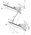


Classifications
-
- H—ELECTRICITY
- H02—GENERATION; CONVERSION OR DISTRIBUTION OF ELECTRIC POWER
- H02S—GENERATION OF ELECTRIC POWER BY CONVERSION OF INFRARED RADIATION, VISIBLE LIGHT OR ULTRAVIOLET LIGHT, e.g. USING PHOTOVOLTAIC [PV] MODULES
- H02S20/00—Supporting structures for PV modules
- H02S20/10—Supporting structures directly fixed to the ground
-
- H—ELECTRICITY
- H02—GENERATION; CONVERSION OR DISTRIBUTION OF ELECTRIC POWER
- H02S—GENERATION OF ELECTRIC POWER BY CONVERSION OF INFRARED RADIATION, VISIBLE LIGHT OR ULTRAVIOLET LIGHT, e.g. USING PHOTOVOLTAIC [PV] MODULES
- H02S20/00—Supporting structures for PV modules
- H02S20/30—Supporting structures being movable or adjustable, e.g. for angle adjustment
- H02S20/32—Supporting structures being movable or adjustable, e.g. for angle adjustment specially adapted for solar tracking
-
- H—ELECTRICITY
- H02—GENERATION; CONVERSION OR DISTRIBUTION OF ELECTRIC POWER
- H02S—GENERATION OF ELECTRIC POWER BY CONVERSION OF INFRARED RADIATION, VISIBLE LIGHT OR ULTRAVIOLET LIGHT, e.g. USING PHOTOVOLTAIC [PV] MODULES
- H02S20/00—Supporting structures for PV modules
- H02S20/30—Supporting structures being movable or adjustable, e.g. for angle adjustment
-
- Y—GENERAL TAGGING OF NEW TECHNOLOGICAL DEVELOPMENTS; GENERAL TAGGING OF CROSS-SECTIONAL TECHNOLOGIES SPANNING OVER SEVERAL SECTIONS OF THE IPC; TECHNICAL SUBJECTS COVERED BY FORMER USPC CROSS-REFERENCE ART COLLECTIONS [XRACs] AND DIGESTS
- Y02—TECHNOLOGIES OR APPLICATIONS FOR MITIGATION OR ADAPTATION AGAINST CLIMATE CHANGE
- Y02E—REDUCTION OF GREENHOUSE GAS [GHG] EMISSIONS, RELATED TO ENERGY GENERATION, TRANSMISSION OR DISTRIBUTION
- Y02E10/00—Energy generation through renewable energy sources
- Y02E10/50—Photovoltaic [PV] energy
Definitions
- the present invention relates to a solar panel unit used for solar power generation and a solar power generation system using the solar panel unit.
- Patent Documents In recent years, it has been considered to install a photovoltaic power generation system in idle land. In such a photovoltaic power generation system, it is important to secure as much power generation as possible, and as a measure therefor, there is one that tracks the direction of the light receiving surface of the photovoltaic power generation panel to the movement of the sun (for example, Patent Documents). 1).
- Patent Document 1 one solar panel unit having an actuator that changes the direction of the photovoltaic power generation panel is provided, and solar panel units that do not have an actuator are arranged in the east-west direction and the north-south direction.
- Each solar panel unit has a link that transmits the operation of the solar panel unit having an actuator to the solar panel units arranged in the east-west direction, and a link that transmits the operation to the solar panel units arranged in the north-south direction.
- the present invention has been made paying attention to the above problems, and it is an object of the present invention to reliably synchronize the orientation of photovoltaic panels when a plurality of photovoltaic panel units are driven by a single actuator. It is said.
- the first aspect is: In the solar panel unit including the support base (12) that supports the solar power generation panel (11) to be slidable around the rotation axis (S),
- the rotating shaft (S) is disposed on one end side, and the rotating shaft (S) is used as a rotation center to transmit a swinging force according to the swinging of the photovoltaic power generation panel (11), or for input of dredging power.
- the first crank mechanism disposed in the other solar panel unit adjacent to the other end side of the rotating shaft (S) has a swinging force according to the swinging of the solar power generation panel (11).
- a second crank mechanism for transmitting It is provided with.
- the swinging force can be transmitted in different directions by the first and second crank mechanisms provided at both ends of the rotating shaft (S). Therefore, as compared with the conventional case where the link member extending in the north-south direction is connected to the link member in the east-west direction, an increase in rigidity of each link mechanism can be expected.
- the second aspect is the first aspect,
- the second crank mechanism constitutes a link mechanism together with the first crank mechanism included in the other solar panel unit,
- Each link member (71, 72, 81) constituting the link mechanism does not pass through the dead point in the swing range of the photovoltaic power generation panel (11).
- each link member (71, 72, 81) since each link member (71, 72, 81) does not pass through the dead center in the swing range, the link mechanism can be swung smoothly.
- the third aspect is the first or second aspect
- the second crank mechanism includes a driven link member (72) serving as a driven node
- the first crank mechanism in the other solar panel unit is A first link member (81) connected to the driven link member (72) and swinging about the rotation shaft (S) according to the operation of the driven link member (72);
- a second link member (82) connected to the first link member (81) and swinging integrally in response to swinging of the first link member (81);
- the angle formed by the connecting line and the line connecting the opposite pairs of both ends of the first link member (81) is equal.
- the amount of displacement on the forward side is equal to the amount of displacement on the return side.
- the fourth aspect is any one of the first to third aspects.
- the second crank mechanism and the first crank mechanism provided in the other solar panel unit operate on the same plane.
- the fifth aspect is any one of the first to fourth aspects.
- the second crank mechanism is detachable.
- the sixth aspect is In the solar power generation system including a plurality of solar panel units, the support base (12) supporting the solar power generation panel (11) so as to be slidable around the rotation axis (S).
- the plurality of solar panel units include A first solar panel unit (10a) having an actuator (51) to swing the solar power generation panel (11); A solar panel unit according to any one of the first to fifth aspects, wherein the solar power generation panel (11) is swung by a crank mechanism (60) of the first solar panel unit (10a).
- Solar panel unit (10b) A third solar panel unit (10c) in which the solar power generation panel (11) is swung by a second crank mechanism of the second solar panel unit (10b); Is included.
- the swinging force by the actuator (51) can be transmitted in different directions by the first and second crank mechanisms provided at both ends of the rotating shaft (S).
- the directions of the solar power generation panels can be more reliably synchronized.
- the link mechanism can be smoothly swung, so that, for example, each photovoltaic power generation panel can be driven without applying an excessive load to the actuator that drives the photovoltaic power generation panel. It becomes possible.
- the principal part of a solar panel unit can be shared.
- a solar panel unit can be easily installed even in a distorted land. Moreover, the direction of each photovoltaic power generation panel can be synchronized more reliably.
- FIG. 1 is a perspective view of a part of the photovoltaic power generation system according to the first embodiment.
- FIG. 2 shows an arrangement example of solar panel units.
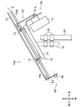
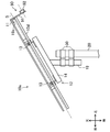
- FIG. 3 is a side view of the first solar panel unit.
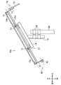
- FIG. 4 is a side view of the second solar panel unit.
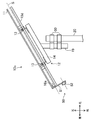
- FIG. 5 is a side view of the third solar panel unit.
- FIG. 6 is a side view of the fifth solar panel unit.
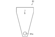
- FIG. 7 shows a planar shape of a link member used for the first solar panel unit.
- FIG. 8 shows a planar shape of a link member used for the second solar panel unit.
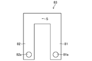
- FIG. 9 shows the planar shape of the link assembly.
- FIG. 10 is a view of the second solar panel unit and the third solar panel unit of FIG. 1 as viewed from the west side.
- FIG. 10 is a view of the second solar panel unit and the third solar panel unit of FIG. 1 as viewed from the west side.
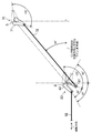
- FIG. 11 is a view of the crank mechanism of the second solar panel unit and the crank mechanism of the third solar panel unit as viewed from the direction of the arrow in FIG.
- FIG. 12 shows a state where the second solar panel units are connected by a crank mechanism.
- FIG. 13 shows a part of the photovoltaic power generation system according to the second embodiment.
- FIG. 14 shows another example of the link assembly.
- Embodiment 1 of the Invention one solar panel unit provided with an actuator for swinging a photovoltaic power generation panel and a solar panel unit not provided with an actuator are connected by a link mechanism, and a plurality of solar panels are connected by one actuator.
- a solar power generation system that drives an optical panel will be described.
- the solar power generation system is installed on an idle land (for example, a farmland that is being fallowed).
- FIG. 1 is a perspective view of a part of the photovoltaic power generation system (1) of the first embodiment.
- the solar power generation system (1) is configured by connecting first to fifth solar panel units (10a, 10b, 10c, 10d, 10e) described later by a link mechanism. Although not shown, the solar power generation system (1) has a power condition for converting the DC power generated by these solar panel units (10a, 10b, 10c, 10d, 10e) into AC power. Na is provided.
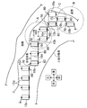
- FIG. 2 shows an arrangement example of the first to fifth solar panel units (10a, 10b, 10c, 10d, 10e).
- the land where the photovoltaic system (1) is installed consists of a long part in the east and west and a long part in the north and south. That is, the solar power generation system (1) is installed on distorted land.
- these solar panel units (10a, 10b, 10c, 10d, 10e) are located on the land so that the light receiving surface (11a) of the solar power generation panel (11), which will be described later, faces south. They are arranged according to the shape (details will be described later).
- FIG. 1 corresponds to the solar panel units (10a, 10b, 10c) in the group (A) surrounded by the alternate long and short dash line in FIG.
- the first solar panel unit (10a) is greatly different from the second, third, fourth, and fifth solar panel units (10b, 10c, 10d, 10e). That is, the first solar panel unit (10a) is provided with the actuator unit (50) for swinging the solar power generation panel (11), but the second solar panel unit (10b) to the fifth solar panel.
- the optical panel unit (10e) is not provided with the actuator unit (50).
- the first solar panel unit (10a), the second solar panel unit (10b), the third solar panel unit (10c), the fourth solar panel unit (10d), and the fifth In the case where it is not necessary to distinguish the solar panel unit (10e), “10” is attached as a reference symbol to represent the solar panel unit (10).
- Each solar panel unit (10) has a solar power generation panel (11) and a support frame (12).
- the solar power generation panel (11) is formed in a plate shape, and one surface is a sunlight receiving surface (11a). Each photovoltaic power generation panel (11) is disposed such that the light receiving surface (11a) is the upper surface, and receives sunlight on the light receiving surface (11a) to generate DC power.
- the light receiving surface (11a) is a rectangle, and is arranged so that the two sides of the rectangle face the north-south direction (that is, the remaining two sides face the east-west direction).
- crosspieces (15a, 15b, 15c, 15d) are fixed to the back surface of the photovoltaic power generation panel (11).
- the crosspieces (15a, 15b) are arranged in parallel to each other in a direction orthogonal to a rotation axis (S) described later.
- the crosspiece members (15c, 15d) are arranged in parallel to each other and orthogonal to the crosspiece members (15a, 15b).
- an angle member having an L-shaped cross section is used as the crosspiece member (15c, 15d).
- the support frame (12) rotatably supports the photovoltaic power generation panel (11). As shown in FIG. 3 and the like, the support frame (12) includes two joint members (13) and a support member (14).
- the support member (14) is a member that supports the photovoltaic power generation panel (11), and is formed of a lip groove type rope (C type rope) having a predetermined length, or channel steel. In this example, C-shaped steel is used so that the opening side is the upper side.
- the two joint members (13) are attached near both ends of the support member (14) so as to be aligned on the same straight line, and the crosspiece members (15a, 15b) are rotatably connected. Thereby, the photovoltaic power generation panel (11) can rotate around a predetermined rotation axis (S).
- the support (14) has a support (19) fixed to it.
- pillar (19) is comprised by the pipe material, for example, and is fastened by the clamp (30) to the pile (20) previously driven into the ground.
- the clamp (30) sandwiches the support (19) and the pile (20) arranged in parallel, and is fixed by a screw mechanism.
- various clamps such as a general-purpose clamp for fastening a building material can be employed.
- each solar panel unit (10) can be rotated (S) by adjusting the fastening position of the clamp (30) and the inclination angle of the support frame (12). Is installed so that the north end of the photovoltaic power generation panel (11) is higher than the south end (see FIG. 1).
- the solar panel units (10) lined up in the east-west direction have an interval in the east-west direction of the support column (19) that is twice the width in the east-west direction of the photovoltaic power generation panel (11) (referred to as the panel width). It is arranged to be. That is, there is a space for the panel width between the photovoltaic power generation panels (11) adjacent in the east-west direction.
- the interval between the support columns (19) in the east-west direction is about 2 m.
- the positional relationship of the solar panel units (10) arranged in the north-south direction is staggered.
- the interval between the solar panel units (10) in the north-south direction will be described later.
- the actuator unit (50) has an actuator (51) and a transmission mechanism (53).
- the actuator (51) of this embodiment is a rotary pneumatic actuator, and rotates the output shaft (51a) by air pressure.
- the rotation angle of the output shaft (51a) can be controlled by controlling the air supply amount.
- the transmission mechanism (53) is specifically a crank mechanism, and swings the photovoltaic power generation panel (11) around the rotation axis (S) according to the rotation of the output shaft (51a). More specifically, in this example, the actuator (51) swings the photovoltaic power generation panel (11) within a range of ⁇ 60 ° with reference to a position where the east-west side of the light receiving surface (11a) is horizontal. be able to.
- the configuration of the actuator (51) is an example, and is not limited to a rotary type, and is not limited to a pneumatic type.
- ⁇ Link mechanism> In the solar power generation system (1), the operation of the solar power generation panel (11) of the first solar panel unit (10a) is changed by the link mechanism to the second, third, fourth, and fifth solar panel units ( 10b, 10c, 10d, 10e), and each photovoltaic power generation panel (11) is synchronized with the movement of the sun. Specifically, in the solar power generation system (1), a crank mechanism is provided in each of the first to fifth solar panel units (10a, 10b, 10c, 10d, 10e), and these crank mechanisms are connected. Thus, the above tracking is realized. Below, the crank mechanism of each solar panel unit (10a, 10b, 10c, 10d, 10e) is demonstrated.
- the first solar panel unit (10a) is provided with a crank mechanism (60) and a bracket (16a).
- the bracket (16a) fixes the crank mechanism (60) to the first solar panel unit (10a).
- an angle member having an L-shaped cross section is used as the bracket (16a), and a crosspiece member (15c) and a crosspiece member (15d) are arranged at the almost south end of the photovoltaic power generation panel (11). It is set up to bridge between the east and west directions.
- the crank mechanism (60) of the first solar panel unit (10a) is for transmitting the movement of the solar power generation panel (11) to the other solar panel units (10). As shown in FIGS. 1 and 3, the crank mechanism (60) is disposed on one end side (here, the south end) of the rotating shaft (S), and is connected to the photovoltaic power generation panel (50) by the actuator unit (50). When 11) swings, the swinging force is transmitted to the other solar panel unit (10) by swinging around the rotation axis (S) according to the swing.
- crank mechanism (60) of the present embodiment includes a link member (61) and a connecting rod (62).
- This crank mechanism (60) is an example of the first crank mechanism of the present invention.
- FIG. 7 shows the planar shape of the link member (61).
- the link member (61) is formed in a substantially isosceles triangle shape by a plate-like member.
- the link member (61) has a bolt (not shown) corresponding to the base of the isosceles triangle so that the tip of the link member (61) extends downward substantially perpendicularly to the photovoltaic panel (11). (See FIG. 1).
- the link member (61) is provided with a through hole (61a) for rotatably pin-connecting the connecting rod (62) in the vicinity of the opposite vertex of the bottom side, that is, in the vicinity of the lower end in the attached state. Yes.
- the position of the through hole (61a) is determined so as to be separated from the rotation shaft (S) by a predetermined distance in a state where the link member (61) is attached to the bracket (16a).
- the connecting rod (62) is a tubular member and connects the link member (61) to another crank mechanism (described later) (see FIG. 1).
- the connecting rod (62) is rotatably connected to the through hole (61a) of the link member (61).
- the pin connection can be realized, for example, by providing a through hole in the connecting rod (62) and connecting the through hole and the through hole (61a) of the link member (61) through a bolt or the like.
- the second solar panel unit (10b) includes a crank mechanism (60), a crank mechanism (70), a bracket (16a), and a bracket (16b).
- the bracket (16a) has the same configuration as that of the first solar panel unit (10a).
- the bracket (16b) is for fixing the crank mechanism (70) to the first solar panel unit (10a).
- an angle member having an L-shaped cross section is used as the bracket (16b), and between the crosspiece member (15c) and the crosspiece member (15d) at the substantially north end of the photovoltaic power generation panel (11). Is built to bridge in the east-west direction.
- the crank mechanism (60) has the same configuration as that of the first solar panel unit (10a). Also, in the second solar panel unit (10b), the crank mechanism (60) is arranged at one end side of the rotating shaft (S), more specifically, at the almost south end of the solar power generation panel (11). (See FIG. 4).
- This crank mechanism (60) is connected to the crank mechanism of the other solar panel unit (10), transmits the swinging force to the crank mechanism of the solar panel unit (10), or receives the swinging force from the other crank mechanism. It has come to be.
- the crank mechanism (60) of the second solar panel unit (10b) is connected to the crank mechanism (60) of the first solar panel unit (10a) by a connecting rod (62). A swinging force is input from the connecting rod (62). That is, the crank mechanism (60) of the second solar panel unit (10b) is an example of the first crank mechanism of the present invention.
- the other crank mechanism (70) is disposed at the other end of the rotating shaft (S), more specifically, at the substantially north end of the photovoltaic power generation panel (11) (FIGS. 1 and 4). reference).
- the crank mechanism (70) transmits a swinging force to a crank mechanism (60) provided in another solar panel unit (10) adjacent on the other end side (the north side in this example) of the rotation shaft (S), Alternatively, a swinging force is input from another crank mechanism.
- the crank mechanism (70) transmits a swinging force to the third solar panel unit (10c).
- This crank mechanism (70) is an example of the second crank mechanism of the present invention.
- the crank mechanism (70) of this embodiment includes a link member (71) and a connecting rod (72).
- Fig. 8 shows the planar shape of the link member (71).
- the link member (71) is formed in a substantially isosceles triangle shape by a plate-like member.
- the link member (71) has a bolt (not shown) corresponding to the base of the isosceles triangle so that the tip of the link member (71) extends downward substantially perpendicularly to the photovoltaic panel (11). ) (See FIG. 4). That is, the crank mechanism (70) is detachable.
- the link member (71) is provided with a through hole (71a) for rotatably connecting the connecting rod (72) in the vicinity of the bottom apex of the bottom side, that is, in the vicinity of the lower end in the attached state. Yes.
- the position of the through hole (71a) is determined so as to be separated from the rotation shaft (S) by a predetermined distance in a state where the link member (71) is attached to the bracket (16b).
- the connecting rod (72) is a tubular member that connects the link member (71) to another crank mechanism (described later). Specifically, one end of the connecting rod (72) is rotatably connected to the through hole (71a) of the link member (71), and the other end is rotatably connected to a link member (described later) of another crank mechanism. It is connected. Therefore, when the photovoltaic panel (11) swings in the second photovoltaic panel unit (10b), the link member (71) swings around the rotation axis (S) together with the photovoltaic panel (11) and is connected.
- the rod (72) follows the link member (71) (see FIG. 1). That is, it can be considered that “turning pair” is formed at both ends of the connecting rod (72).
- the connecting rod (72) is a member that becomes a driven node in the crank mechanism (70), and is an example of a driven link member of the present invention. Connection between the connecting rod (72) and another crank mechanism will be described later.
- the third solar panel unit (10c) is provided with a crank mechanism (80).
- the crank mechanism (80) is adjacent in the east-west direction while swinging according to the swinging force from other solar panel units (10) adjacent in the north-south direction (in the example of FIG. 1, precisely the southeast side). The swinging force is transmitted to the other solar panel unit (10).
- This crank mechanism (80) is an example of the first crank mechanism of the present invention.
- the crank mechanism (80) includes a link member (81), a link member (82), and a connecting rod (62).
- the link member (81) is connected to the connecting rod (72) provided in the second solar panel unit (10b) adjacent in the north-south direction, and swings about the rotation axis (S) (see FIG. 1). Further, the link member (82) is formed integrally with the link member (81). When the link member (81) swings in the crank mechanism (80), the link member (82) is also integrated. Oscillates. That is, the link member (82) and the link member (81) have the rotation axis (S) as a common rotation axis.
- the link member (81) is an example of the first link member of the present invention
- the link member (82) is an example of the second link member (82) of the present invention.
- the connecting rod (62) is a tubular member, and is used to transmit the swinging force to the solar panel unit (10) adjacent in the east-west direction.
- a swinging force may be input to the connecting rod (62).
- one end of the connecting rod (62) is rotatably connected to the link member (82), and the other end is connected to the link member (61) included in the other solar panel unit (10). Pin connected.
- the connecting rod (62) swings according to the swing of the link member (82) to swing the link member (61) included in the other solar panel unit (10). That is, it can be considered that a turning pair is formed at both ends of the connecting rod (62).
- the third solar panel unit (10c) in the group (A) is a crank mechanism of the fourth solar panel unit (10d) adjacent to the west side (the crank mechanism (60) as will be described later).
- the rocking force is transmitted by the connecting rod (62).
- the connecting rod (62) is an example of the third link member of the present invention.
- FIG. 9 shows the planar shapes of the link member (81) and the link member (82).
- the link member (81) and the link member (82) are integrally formed by processing a plate-like member into a U-shape.
- these integrally formed link members (81, 82) will be referred to as a link assembly (83).
- the link assembly (83) includes a bracket (16a) such that the end of each link member (81, 82) extends downward substantially perpendicularly to the photovoltaic panel (11). It is fixed to.
- a through hole (81a) for rotatably pin-connecting the link member (71) provided in the adjacent second solar panel unit (10b) at the tip of the link member (81). ) Is formed. That is, it can be considered that the turning pair is formed at both ends of the link member (81), and the link member (81) is provided with the crank mechanism (70) provided in the connected second solar panel unit (10b). Together with this, a four-bar linkage mechanism is formed.
- a through hole (82a) for rotatably connecting the connecting rod (62) to the pin is formed at the tip of the link member (82). Therefore, it can be considered that a rotating pair is formed at both ends of the link member (82), and the link member (82) and the connecting rod (62) are provided with crank mechanisms (10) included in the other solar panel unit (10). 60) and a four-bar linkage mechanism.
- the fourth solar panel unit (10d) includes only the crank mechanism (60) as a crank mechanism (see FIG. 2). That is, if the crank mechanism (70) is not attached to the second solar panel unit (10b), the fourth solar panel unit (10d) is obtained.
- the crank mechanism (60) of the fourth solar panel unit (10d) is also an example of the first crank mechanism of the present invention.
- the fifth solar panel unit (10e) is provided with a crank mechanism (90).
- the crank mechanism (90) is disposed at the other end side of the rotating shaft (S), more specifically, at the substantially north end of the photovoltaic power generation panel (11). Then, the swinging force is transmitted to the crank mechanism (90) from the crank mechanism (70) provided in the second solar panel unit (10b) adjacent in the east-west direction (see FIG. 2). That is, the crank mechanism (90) is an example of the first crank mechanism of the present invention.
- the crank mechanism (90) of this embodiment includes a link member (91) and a connecting rod (92).
- the link member (91) has the same shape as the link member (71) provided in the crank mechanism (70) of the second solar panel unit (10b) (see FIG. 8).
- the link member (91) is fixed to the bracket (16b).
- the connecting rod (92) is a tubular member and is connected to the link member (71) of the crank mechanism (70) included in the second solar panel unit (10b) adjacent in the east-west direction (see FIG. 2). .
- the connecting rod (92) has one end rotatably connected to the vicinity of the lower end of the link member (91) and the other end connected to the link member (71).
- the link member (71) is pin-coupled using the through hole (71a). That is, the crank mechanism (90) forms a four-bar linkage mechanism together with the crank mechanism (70) provided in the second solar panel unit (10b) adjacent in the east-west direction.
- FIG. 10 is a view of the second solar panel unit (10b) and the third solar panel unit (10c) of FIG. 1 as viewed from the west side.
- the crank mechanism (70) of the second solar panel unit (10b) and the crank mechanism (80) of the third solar panel unit (10c) operate on the same plane (V). It is supposed to be.
- the plane (V) is orthogonal to the rotation axis (S).
- the distance between the second solar panel unit (10b) and the third solar panel unit (10c) in the north-south direction is set. Adjust it.
- FIG. 11 is a view of the crank mechanism (70) of the second solar panel unit (10b) and the crank mechanism (80) of the third solar panel unit (10c) as seen from the direction of the arrow in FIG. .
- FIG. 11 shows a state in which the solar power generation panel (11) is inclined most east.
- a link member constituting a four-joint link mechanism formed by a crank mechanism (70) and a crank mechanism (80), more specifically, a link member (71), a connecting rod (72), a link member (81) is the dead center in the swing range of the photovoltaic panel (11) (in this example, a range of ⁇ 60 ° with respect to the position where the side in the east-west direction of the light receiving surface (11a) is horizontal).
- the arrangement and the like are determined so as not to pass.
- the angle formed by the line connecting the turning pair formed at both ends of the link member (81) and the line connecting the turning pair formed at both ends of the connecting rod (72) is the smallest.
- the photovoltaic power generation panel (11) is tilted to the east (the state where the connecting rod (62) has moved to the west most), and the angle between the two in that state is more than 0 ° (specifically, In this example, it is 30 °) and does not pass through the dead point.
- the four-bar linkage mechanism can be smoothly swung. That is, in this embodiment, it is possible to swing each photovoltaic power generation panel (11) without applying an excessive load to the actuator (51).
- the connecting rod (72) is inclined by 40 ° with respect to the swinging direction of the connecting rod (62).
- the rocking direction of the connecting rod (62) is a direction along a line that connects the shortest pairs formed at both ends of the connecting rod (62) to the shortest, and this rocking direction is a horizontal direction.
- fluctuation direction (horizontal direction) of a connection rod (62) makes is 40 degrees.
- the line connecting the opposite pairs of both ends of the connecting rod (72) is the shortest distance between the center of the through hole (71a) of the link member (71) and the center of the through hole (81a) of the link member (81). It is a line connecting to. And this angle (40 degrees) is mainly decided according to the space
- the angle formed by the line connecting the pair of ends around the both ends of the link member (82) and the line connecting the pair of ends of the link member (81) is 40 °.
- the line connecting the turning pairs of both ends of the link member (82) is the line connecting the center of the through hole (82a) of the link member (82) and the rotation axis (S) in the shortest distance.
- the line connecting the turning pairs of both ends of the link member (81) is the line connecting the center of the through hole (81a) of the link member (81) and the rotation axis (S) in the shortest distance.
- the angle formed by the line connecting each other and the line connecting the opposite pairs of both ends of the link member (81) is equal.
- the link member (82) that drives the connecting rod (62) swings within a range of ⁇ 60 ° about the vertical line. To do. That is, in the reciprocating motion of the link member (82), the amount of displacement on the forward side is equal to the amount of displacement on the return side. In other words, the link member (82) swings equally in the east-west direction.
- FIG. 12 shows a state in which the second solar panel units (10b) are connected by the crank mechanism (70).
- the example of FIG. 12 corresponds to the two second solar panel units (10b) included in the group (B) surrounded by the alternate long and short dash line in FIG.
- the crank mechanism (60) included in the second solar panel unit (10b) on the north side and the crank mechanism (70) included in the second solar panel unit (10b) on the south side are connected. .
- crank mechanism (60) provided in the second solar panel unit (10b) on the north side corresponds to the second crank mechanism of the present invention
- crank provided in the second solar panel unit (10b) on the south side corresponds to the first crank mechanism of the present invention.
- the second solar panel unit (10b) can transmit the swinging force to the fifth solar panel unit (10e).
- another solar panel unit (10) is arranged on the east side of the second solar panel unit (10b), and further, another solar panel unit (10b) is placed on the southeast side of the second solar panel unit (10b). This is convenient when two solar panel units (10b) are arranged.
- the solar panel units (10a, 10b, 10e) in the group (C) surrounded by the alternate long and short dash line correspond to this.
- the fourth solar panel unit (10d) is arranged instead of the fifth solar panel unit (10e) in the group (C) of FIG. 2, the fourth solar panel unit (10d)
- the second solar panel unit (10b) adjacent to the east is connected by the crank mechanism (60).
- the crank mechanism (60) of the fourth solar panel unit (10d) and the second solar panel unit (10b) adjacent to the west are connected to the second solar panel unit (10b) on the southeast side.
- the crank mechanism (60) originally provided with the connecting rod (62) has a positional relationship in which the connecting rods (62) easily interfere with each other.
- the crank mechanism (70) corresponds to the first crank mechanism of the present invention.
- the crank mechanism (60) corresponds to the second crank mechanism.
- the actuator (51) of the first solar panel unit (10a) is controlled by a control unit (not shown) configured using a microcomputer or the like, and the solar power generation panel (11) The direction is tracked by the movement of the sun.
- the crank mechanism (60) of the first solar panel unit (10a) swings the crank mechanism (60) of the second solar panel unit (10b) adjacent to the west so that the second solar panel unit ( The solar panel (11) in 10b) also tracks the movement of the sun.
- the second solar panel unit (10b) swings the crank mechanism (80) of the third solar panel unit (10c) adjacent to the west by the crank mechanism (70).
- the solar power generation panel (11) tracks the movement of the sun.
- the first solar panel unit (10a) swings the crank mechanism (70) of the second solar panel unit (10b) located on the southeast side by the crank mechanism (60).
- the second solar panel unit (10b) includes a crank mechanism (90) of the fifth solar panel unit (10e) adjacent to the east, and a crank mechanism (70) of the second solar panel unit (10b) on the southeast side. Oscillate.
- the first solar panel unit (10a) is used to swing the other solar panel units (10) in the solar power generation system (1). Power is transmitted sequentially, and as a result, all photovoltaic power generation panels (11) in the photovoltaic power generation system (1) track the movement of the sun.
- the solar panel unit (10) provided with the crank mechanisms (60, 70) at both ends of the rotating shaft (S) is arranged in the solar power generation system (1),
- the rocking force was transmitted to the solar panel unit (10) adjacent in the east-west direction and the north-south direction. Therefore, as compared with the conventional case where the link member extending in the north-south direction is connected to the link member in the east-west direction, an increase in rigidity of each link mechanism can be expected. Therefore, according to this embodiment, when driving a plurality of solar panel units (10) with one actuator (51), the direction of the solar power generation panel (11) can be more reliably synchronized. It becomes possible.
- the solar panel unit can be easily installed even in distorted land.
- FIG. 13 shows a part of the photovoltaic power generation system (1) according to Embodiment 2 of the present invention.
- FIG. 13 is a view of the connected state of two second solar panel units (10b) and one third solar panel unit (10c) as viewed from the west side.
- the second solar panel unit (10b) located at the center extends the crosspiece member (15c) and the crosspiece member (15d) both north and south. This places the bracket (16a) further south than the south end of the photovoltaic panel (11), and the bracket (16b) further north than the north end of the photovoltaic panel (11). Can be arranged.
- the crank mechanism (70) of the second solar panel unit (10b) at the center and the crank mechanism (80) of the third solar panel unit (10c) Can be operated on the same plane (V), and the distance between the second solar panel unit (10b) and the third solar panel unit (10c) in the north-south direction can be increased.
- the bracket (16a) in this way the crank mechanism (60) provided in the central second solar panel unit (10b) and the second solar panel unit (10b) in the south end are provided. It is possible to increase the distance between the second solar panel units (10b) in the north-south direction while operating the crank mechanism (70) on the same plane (V).
- the distance between the north and south directions can be increased in this way, at the place where the solar panel units (10) are arranged in the north and south direction, one is less likely to be in the shade of the other. That is, in the present embodiment, the same effect as in the first embodiment can be obtained, and an improvement in power generation efficiency can be expected.
- Embodiment 3 of the Invention demonstrates the example which arrange
- FIG. 14 shows an example of a link assembly (83) capable of taking measures against interference between connecting rods.
- each of the connecting rod (62) and the connecting rod (72) is pin-connected on the opposite surfaces of the link assembly (83).
- the connecting rod (72) is attached to the front side of the page with respect to the link assembly (83), and the connecting rod (62) is attached to the back side of the page with respect to the link assembly (83). Yes.
- interference between the link members can be prevented by attaching the connecting rod (62) and the connecting rod (72) to the opposite surfaces of the link assembly (83).
- the actuator unit (50) may be incorporated in any of the second solar panel units (10b).
- the inclination angle of the connecting rod (72), the swinging range of the photovoltaic power generation panel (11), the interval between the columns (19), etc. are examples.
- the inclination direction when the solar power generation panel (11) is installed is also an example.
- the solar power generation panel (11) may be installed such that the north end is lower than the south end.
- crank mechanism (70) of the second solar panel unit (10b) and the crank mechanism (for example, the crank mechanism (80)) of the other solar panel unit (10) need to be operated on the same plane. There is no.
- a pillow ball may be used to connect the link member and the connecting rod.
- a pillow ball may be used to connect the link member (71) and the connecting rod (72) and to connect the link member (81) and the connecting rod (72).
- the present invention is useful as a solar panel unit used for solar power generation and a solar power generation system using the solar panel unit.
Landscapes
- Life Sciences & Earth Sciences (AREA)
- Sustainable Development (AREA)
- Photovoltaic Devices (AREA)
- Transmission Devices (AREA)
Abstract
回転軸(S)の一端側に配置され、該回転軸(S)を回転中心として、太陽光発電パネル(11)の揺動に応じて揺動力を伝達、若しくは搖動力の入力に応じて太陽光発電パネル(11)を揺動させる第1クランク機構を設ける。回転軸(S)の他端側に配置され、該他端側において隣接する他の太陽光パネルユニットが備える第1クランク機構に太陽光発電パネル(11)の揺動に応じて揺動力を伝達する第2クランク機構を設ける。
Description
本発明は、太陽光発電に用いる太陽光パネルユニット、及びそれを用いた太陽光発電システムに関するものである。
近年、遊休地などに太陽光発電システムを設置することが検討されている。このような太陽光発電システムでは、なるべく多くの発電量を確保することが重要であり、その方策として、太陽光発電パネルの受光面の向きを太陽の動きに追尾させるものがある(例えば特許文献1を参照)。特許文献1の例では、太陽光発電パネル向きを変えるアクチュエータを有した1台の太陽光パネルユニットを設け、その東西方向及び南北方向にアクチュエータを持たない太陽光パネルユニットを並べている。そして、各太陽光パネルユニットには、アクチュエータを有した太陽光パネルユニットの動作を東西方向に並んだ太陽光パネルユニットに伝達するリンク部と、南北方向に並んだ太陽光パネルユニットに伝達するリンク部とを設けている。
しかしながら、特許文献1の例では、東西方向のリンク部と南北方向のリンク部とが格子状に連結されており、太陽を追尾してリンク部が東西方向に動作すると南北方向のリンク部が撓んで、南北方向の太陽光発電パネル間で受光面の向きが微妙にずれる可能性がある。また、歪な土地に太陽光パネルユニットを設置する場合には、リンク部を格子状に繋ぐこと自体が難しい。
本発明は上記の問題に着目してなされたものであり、複数台の太陽光パネルユニットを一つのアクチュエータで駆動する場合に、太陽光発電パネルの向きを確実に同期できるようにすることを目的としている。
上記の課題を解決するため、第1の態様は、
太陽光発電パネル(11)を回転軸(S)の回りに搖動可能に支持する支持架台(12)を備えた太陽光パネルユニットにおいて、
上記回転軸(S)の一端側に配置され、該回転軸(S)を回転中心として、上記太陽光発電パネル(11)の揺動に応じて揺動力を伝達、若しくは、搖動力の入力に応じて上記太陽光発電パネル(11)を揺動させる第1クランク機構と、
上記回転軸(S)の他端側に配置され、該他端側において隣接する他の太陽光パネルユニットが備える第1クランク機構に上記太陽光発電パネル(11)の揺動に応じて揺動力を伝達する第2クランク機構と、
を備えたことを特徴とする。
太陽光発電パネル(11)を回転軸(S)の回りに搖動可能に支持する支持架台(12)を備えた太陽光パネルユニットにおいて、
上記回転軸(S)の一端側に配置され、該回転軸(S)を回転中心として、上記太陽光発電パネル(11)の揺動に応じて揺動力を伝達、若しくは、搖動力の入力に応じて上記太陽光発電パネル(11)を揺動させる第1クランク機構と、
上記回転軸(S)の他端側に配置され、該他端側において隣接する他の太陽光パネルユニットが備える第1クランク機構に上記太陽光発電パネル(11)の揺動に応じて揺動力を伝達する第2クランク機構と、
を備えたことを特徴とする。
この構成では、回転軸(S)の両端に設けられた、第1及び第2クランク機構のそれぞれによって、互いに異なる方向に、揺動力を伝達することができる。そのため、従来のように、東西方向のリンク部材に南北に長く延びたリンク部材を繋いだものと比べ、各リンク機構の剛性アップを期待できる。
また、第2の態様は、第1の態様において、
上記第2クランク機構は、上記他の太陽光パネルユニットが備える第1クランク機構とともにリンク機構を構成し、
上記リンク機構を構成する各リンク部材(71,72,81)は、上記太陽光発電パネル(11)の揺動範囲において、死点を通過しないことを特徴とする。
上記第2クランク機構は、上記他の太陽光パネルユニットが備える第1クランク機構とともにリンク機構を構成し、
上記リンク機構を構成する各リンク部材(71,72,81)は、上記太陽光発電パネル(11)の揺動範囲において、死点を通過しないことを特徴とする。
この構成では、各リンク部材(71,72,81)が揺動範囲において死点を通過しないので、上記リンク機構をスムーズに揺動させることができる。
また、第3の態様は、第1又は第2の態様において、
上記第2クランク機構は、従動節となる従動リンク部材(72)を備え、
上記他の太陽光パネルユニットにおける第1クランク機構は、
上記従動リンク部材(72)に連結されて、該従動リンク部材(72)の動作に応じて上記回転軸(S)を中心に揺動する第1リンク部材(81)と、
上記第1リンク部材(81)に連結され、該第1リンク部材(81)の揺動に応じて一体的に揺動する第2リンク部材(82)と、
上記他の太陽光パネルユニットとは更に別の太陽光パネルユニットが備える第1クランク機構と、上記第2リンク部材(82)とに連結されて揺動する第3リンク部材(62)と、
を備え、
上記従動リンク部材(72)の両端の回り対偶同士を結ぶ線と上記第3リンク部材(62)の揺動方向とがなす角と、上記第2リンク部材(82)の両端の回り対偶同士を結ぶ線と第1リンク部材(81)の両端の回り対偶同士を結ぶ線とがなす角とは等しいことを特徴とする。
上記第2クランク機構は、従動節となる従動リンク部材(72)を備え、
上記他の太陽光パネルユニットにおける第1クランク機構は、
上記従動リンク部材(72)に連結されて、該従動リンク部材(72)の動作に応じて上記回転軸(S)を中心に揺動する第1リンク部材(81)と、
上記第1リンク部材(81)に連結され、該第1リンク部材(81)の揺動に応じて一体的に揺動する第2リンク部材(82)と、
上記他の太陽光パネルユニットとは更に別の太陽光パネルユニットが備える第1クランク機構と、上記第2リンク部材(82)とに連結されて揺動する第3リンク部材(62)と、
を備え、
上記従動リンク部材(72)の両端の回り対偶同士を結ぶ線と上記第3リンク部材(62)の揺動方向とがなす角と、上記第2リンク部材(82)の両端の回り対偶同士を結ぶ線と第1リンク部材(81)の両端の回り対偶同士を結ぶ線とがなす角とは等しいことを特徴とする。
この構成では、第2リンク部材(82)の往復運動において、往き側の変位量と帰り返り側の変位量とが等しくなる。
また、第4の態様は、第1から第3の態様の何れかにおいて、
上記第2クランク機構と、上記他の太陽光パネルユニットが備える第1クランク機構とは、同一平面上で動作することを特徴とする。
上記第2クランク機構と、上記他の太陽光パネルユニットが備える第1クランク機構とは、同一平面上で動作することを特徴とする。
この構成では、各クランク機構の回り対偶をスムーズに動作させることができる。
また、第5の態様は、第1から第4の態様の何れかにおいて、
上記第2クランク機構は、着脱可能であることを特徴とする。
上記第2クランク機構は、着脱可能であることを特徴とする。
また、第6の態様は、
太陽光発電パネル(11)を回転軸(S)の回りに搖動可能に支持する支持架台(12)を有した、複数の太陽光パネルユニットを備えた太陽光発電システムにおいて、
上記複数の太陽光パネルユニットには、
アクチュエータ(51)を有して上記太陽光発電パネル(11)を揺動させる第1太陽光パネルユニット(10a)と、
第1から第5の態様の何れかの太陽光パネルユニットであって上記第1太陽光パネルユニット(10a)が有するクランク機構(60)によって上記太陽光発電パネル(11)が揺動する第2太陽光パネルユニット(10b)と、
上記第2太陽光パネルユニット(10b)が有する第2クランク機構によって上記太陽光発電パネル(11)が揺動する第3太陽光パネルユニット(10c)と、
が含まれることを特徴とする。
太陽光発電パネル(11)を回転軸(S)の回りに搖動可能に支持する支持架台(12)を有した、複数の太陽光パネルユニットを備えた太陽光発電システムにおいて、
上記複数の太陽光パネルユニットには、
アクチュエータ(51)を有して上記太陽光発電パネル(11)を揺動させる第1太陽光パネルユニット(10a)と、
第1から第5の態様の何れかの太陽光パネルユニットであって上記第1太陽光パネルユニット(10a)が有するクランク機構(60)によって上記太陽光発電パネル(11)が揺動する第2太陽光パネルユニット(10b)と、
上記第2太陽光パネルユニット(10b)が有する第2クランク機構によって上記太陽光発電パネル(11)が揺動する第3太陽光パネルユニット(10c)と、
が含まれることを特徴とする。
この構成では、回転軸(S)の両端に設けられた、第1及び第2クランク機構のそれぞれによって、アクチュエータ(51)による揺動力を、互いに異なる方向に伝達することができる。
第1の態様によれば、複数台の太陽光パネルユニットを一つのアクチュエータで駆動する場合に、太陽光発電パネルの向きをより確実に同期させることが可能になる。
また、第2の態様によれば、リンク機構をスムーズに揺動させることができるので、例えば、太陽光発電パネル駆動するアクチュエータに過大な負荷を与えることなく各太陽光発電パネルを駆動することが可能になる。
また、第3の態様によれば、太陽光発電パネル駆動するアクチュエータに過大な負荷を与えることなく各太陽光発電パネルを駆動することが可能になる。
また、第4の態様によれば、太陽光発電パネルの向きをより確実に同期させることが可能になる。
また、第5の態様によれば、太陽光パネルユニットの主要部を共通化できる。
また、第6の態様によれば、例えば、歪な土地であっても容易に太陽光パネルユニットを設置することができる。また、各太陽光発電パネルの向きをより確実に同期できるようにすることができる。
以下、本発明の実施形態について図面を参照しながら説明する。なお、以下の実施形態は、本質的に好ましい例示であって、本発明、その適用物、あるいはその用途の範囲を制限することを意図するものではない。
《発明の実施形態1》
この実施形態では、太陽光発電パネルを揺動させるアクチュエータを備えた1台の太陽光パネルユニットと、アクチュエータを備えていない太陽光パネルユニットとをリンク機構で連結し、1つのアクチュエータで複数の太陽光パネルを駆動する太陽光発電システムの例を説明する。この例では、太陽光発電システムは、遊休地(例えば休耕中の農地など)に設置される。
この実施形態では、太陽光発電パネルを揺動させるアクチュエータを備えた1台の太陽光パネルユニットと、アクチュエータを備えていない太陽光パネルユニットとをリンク機構で連結し、1つのアクチュエータで複数の太陽光パネルを駆動する太陽光発電システムの例を説明する。この例では、太陽光発電システムは、遊休地(例えば休耕中の農地など)に設置される。
〈システムの全体構成〉
図1は、実施形態1の太陽光発電システム(1)の一部分の斜視図である。太陽光発電システム(1)は、後述する第1から第5太陽光パネルユニット(10a,10b,10c,10d,10e)がリンク機構によって連結されて構成されている。また、図示を省略しているが、太陽光発電システム(1)には、これらの太陽光パネルユニット(10a,10b,10c,10d,10e)で発電した直流電力を交流電力に変換するパワーコンディショナが設けられている。
図1は、実施形態1の太陽光発電システム(1)の一部分の斜視図である。太陽光発電システム(1)は、後述する第1から第5太陽光パネルユニット(10a,10b,10c,10d,10e)がリンク機構によって連結されて構成されている。また、図示を省略しているが、太陽光発電システム(1)には、これらの太陽光パネルユニット(10a,10b,10c,10d,10e)で発電した直流電力を交流電力に変換するパワーコンディショナが設けられている。
図2は、第1から第5太陽光パネルユニット(10a,10b,10c,10d,10e)の配置例を示す。この例では、太陽光発電システム(1)が設置される土地は、東西に長い部分と南北に長い部分からなる。すなわち、太陽光発電システム(1)は、歪な土地に設置されている。図2に示すように、これらの太陽光パネルユニット(10a,10b,10c,10d,10e)は、後述する太陽光発電パネル(11)の受光面(11a)が南を向くように、土地の形状に合わせて配置されている(詳細は後述)。なお、図1は、図2において一点鎖線で囲んだグループ(A)内の太陽光パネルユニット(10a,10b,10c)に対応している。
〈太陽光パネルユニット〉
第1太陽光パネルユニット(10a)は、第2、第3、第4、第5太陽光パネルユニット(10b,10c,10d,10e)と大きな相違点がある。すなわち、第1太陽光パネルユニット(10a)には、太陽光発電パネル(11)を揺動させるアクチュエータユニット(50)が設けられているが、第2太陽光パネルユニット(10b)~第5太陽光パネルユニット(10e)にはアクチュエータユニット(50)が設けられていない。なお、以下の説明では、第1太陽光パネルユニット(10a)、第2太陽光パネルユニット(10b)、第3太陽光パネルユニット(10c)、第4太陽光パネルユニット(10d)、及び第5太陽光パネルユニット(10e)を区別する必要がない場合などには、参照符合として「10」を付して太陽光パネルユニット(10)と表すことにする。
第1太陽光パネルユニット(10a)は、第2、第3、第4、第5太陽光パネルユニット(10b,10c,10d,10e)と大きな相違点がある。すなわち、第1太陽光パネルユニット(10a)には、太陽光発電パネル(11)を揺動させるアクチュエータユニット(50)が設けられているが、第2太陽光パネルユニット(10b)~第5太陽光パネルユニット(10e)にはアクチュエータユニット(50)が設けられていない。なお、以下の説明では、第1太陽光パネルユニット(10a)、第2太陽光パネルユニット(10b)、第3太陽光パネルユニット(10c)、第4太陽光パネルユニット(10d)、及び第5太陽光パネルユニット(10e)を区別する必要がない場合などには、参照符合として「10」を付して太陽光パネルユニット(10)と表すことにする。
図3、図4、図5、及び図6は、それぞれ、第1太陽光パネルユニット(10a)、第2太陽光パネルユニット(10b)、第3太陽光パネルユニット(10c)、第5太陽光パネルユニット(10e)の側面図である。まず、これらの太陽光パネルユニット(10a,10b,10c,10d,10e)に共通する構造について説明する。
それぞれの太陽光パネルユニット(10)は、太陽光発電パネル(11)と支持架台(12)とを有している。
太陽光発電パネル(11)は、板状に形成され、一方の面が太陽光の受光面(11a)である。各太陽光発電パネル(11)は、受光面(11a)が上面となるように配置され、太陽光を受光面(11a)に受けて直流電力を発生する。なお、この例では、受光面(11a)は長方形であり、この長方形の2辺が南北方向を向くように配置される(すなわち、残りの2辺が東西方向を向く)。
また、太陽光発電パネル(11)の裏面には、4本の桟部材(15a,15b,15c,15d)が固定されている。これらのうち、桟部材(15a,15b)は、後述の回転軸(S)と直交する方向に、互いに並行に配置されている。また、桟部材(15c,15d)は、互いに並行で、且つ桟部材(15a,15b)と直交するように配置されている。なお、この例では、桟部材(15c,15d)として、断面がL字型のアングル部材を用いた。
支持架台(12)は、太陽光発電パネル(11)を回転自在に支持する。図3等に示すように、支持架台(12)は、2つの接手部材(13)と支持部材(14)とを有している。支持部材(14)は、太陽光発電パネル(11)を支える部材であり、所定長さを有したリップ溝型綱(C型綱)、或いはチャンネル鋼で形成されている。この例では、C型鋼が、その開口側が上側となるように用いられている。
また、2つの接手部材(13)は、同一直線上に並ぶように、支持部材(14)の両端付近に取り付けられるとともに、桟部材(15a,15b)が回転自在に接続されている。それにより、太陽光発電パネル(11)は、所定の回転軸(S)周りに回転できる。
支持部材(14)には、支柱(19)が固定されている。この支柱(19)は、例えば、パイプ材で構成され、予め地中に打ち込まれた杭(20)にクランプ(30)によって締結される。この例では、クランプ(30)は、平行に並んだ支柱(19)と杭(20)とを挟み込んで、ネジ機構によって固定する。クランプ(30)には、例えば建築資材を締結する汎用のクランプなど種々のクランプを採用できる。このように、太陽光パネルユニット(10)においてクランプ(30)による締結構造を採用したことにより、太陽光発電システム(1)の移設や撤去が容易になる。
そして、太陽光発電システム(1)では、クランプ(30)の締結位置や、支持架台(12)の傾斜角度を調整することによって、それぞれの太陽光パネルユニット(10)が、回転軸(S)が南北方向を向き、且つ太陽光発電パネル(11)の北側端部の方が南側端部よりも高くなるように設置されている(図1参照)。
このとき、東西方向に並んだ太陽光パネルユニット(10)同士は、支柱(19)の東西方向の間隔が太陽光発電パネル(11)の東西方向の幅(パネル幅と呼ぶ)の2倍となるように配置されている。すなわち、東西方向に隣接する太陽光発電パネル(11)の間には、パネル幅分のスペースができる。なお、この例では、支柱(19)の東西方向の間隔は約2mである。
一方、南北方向に並ぶ太陽光パネルユニット(10)の位置関係は、千鳥配置となっている。南北方向の太陽光パネルユニット(10)同士の間隔については、後に説明する。
〈アクチュエータユニット〉
既述の通り、太陽光発電システム(1)では、第1太陽光パネルユニット(10a)が1台のみ設けられ、その第1太陽光パネルユニット(10a)にのみアクチュエータユニット(50)が設けられている(図3参照)。
既述の通り、太陽光発電システム(1)では、第1太陽光パネルユニット(10a)が1台のみ設けられ、その第1太陽光パネルユニット(10a)にのみアクチュエータユニット(50)が設けられている(図3参照)。
図3に示すように、アクチュエータユニット(50)は、アクチュエータ(51)と、伝達機構(53)とを有している。本実施形態のアクチュエータ(51)は、回転式の空気圧アクチュエータであり、空気圧によって出力軸(51a)を回転させる。出力軸(51a)の回転角は、空気の供給量の制御によって制御できる。伝達機構(53)は、具体的にはクランク機構であり、出力軸(51a)の回転に応じて太陽光発電パネル(11)を回転軸(S)周りに揺動させる。より詳しくは、この例では、アクチュエータ(51)は、受光面(11a)の東西方向の辺が水平となる位置を基準に、±60°の範囲で太陽光発電パネル(11)を揺動させることができる。なお、アクチュエータ(51)の構成は例示であり、回転式のものに限定されないし、空気圧式のものにも限定されない。
〈リンク機構〉
太陽光発電システム(1)では、リンク機構によって、第1太陽光パネルユニット(10a)の太陽光発電パネル(11)の動作を、第2、第3、第4、第5太陽光パネルユニット(10b,10c,10d,10e)に伝達し、各太陽光発電パネル(11)が同期して太陽の動きに追尾するようになっている。具体的に、太陽光発電システム(1)では、第1から第5太陽光パネルユニット(10a,10b,10c,10d,10e)のそれぞれにクランク機構が設けられ、これらのクランク機構が連結されることによって、上記追尾を実現している。以下では、各太陽光パネルユニット(10a,10b,10c,10d,10e)のクランク機構について説明する。
太陽光発電システム(1)では、リンク機構によって、第1太陽光パネルユニット(10a)の太陽光発電パネル(11)の動作を、第2、第3、第4、第5太陽光パネルユニット(10b,10c,10d,10e)に伝達し、各太陽光発電パネル(11)が同期して太陽の動きに追尾するようになっている。具体的に、太陽光発電システム(1)では、第1から第5太陽光パネルユニット(10a,10b,10c,10d,10e)のそれぞれにクランク機構が設けられ、これらのクランク機構が連結されることによって、上記追尾を実現している。以下では、各太陽光パネルユニット(10a,10b,10c,10d,10e)のクランク機構について説明する。
-第1太陽光パネルユニット-
図3に示すように、第1太陽光パネルユニット(10a)には、クランク機構(60)、及びブラケット(16a)が設けられている。
図3に示すように、第1太陽光パネルユニット(10a)には、クランク機構(60)、及びブラケット(16a)が設けられている。
ブラケット(16a)は、クランク機構(60)を第1太陽光パネルユニット(10a)に固定するものである。この例では、ブラケット(16a)として、断面がL字型のアングル部材を用いており、太陽光発電パネル(11)のほぼ南の端に、桟部材(15c)と桟部材(15d)との間を東西方向に橋渡しするように設けてある。
第1太陽光パネルユニット(10a)のクランク機構(60)は、太陽光発電パネル(11)の動きを他の太陽光パネルユニット(10)に伝達するためものである。このクランク機構(60)は、図1、及び図3に示すように、回転軸(S)の一端側(ここでは、南側の端)に配置され、アクチュエータユニット(50)によって太陽光発電パネル(11)が揺動すると、その揺動に応じて回転軸(S)を回転中心として揺動することによって揺動力を他の太陽光パネルユニット(10)に伝達する。
具体的に、本実施形態のクランク機構(60)は、リンク部材(61)と連結ロッド(62)とを有している。このクランク機構(60)は、本発明の第1クランク機構の一例である。
図7に、リンク部材(61)の平面形状を示す。リンク部材(61)は、板状の部材によって略二等辺三角形状に形成したものである。このリンク部材(61)は、その先端が太陽光発電パネル(11)に対して概ね垂直に下向きに延びるように、上記二等辺三角形の底辺に相当する部分がブラケット(16a)にボルト(図示は省略)によって固定されている(図1参照)。また、リンク部材(61)は、上記底辺の対頂点の付近、すなわち取り付け状態で下端となる付近に、連結ロッド(62)を回転自在にピン連結するための貫通孔(61a)が設けられている。貫通孔(61a)は、リンク部材(61)をブラケット(16a)に取り付けた状態において、回転軸(S)から所定距離だけ離れるように、その位置が定められている。
連結ロッド(62)は、円管状の部材であり、他のクランク機構(後述)にリンク部材(61)を連結するものである(図1参照)。連結ロッド(62)は、リンク部材(61)の貫通孔(61a)に、回転自在にピン連結されている。ピン連結は、例えば、連結ロッド(62)にも貫通孔を設けておいて、その貫通孔とリンク部材(61)の貫通孔(61a)とにボルトなどを通して結合することで実現できる。この構成により、第1太陽光パネルユニット(10a)において太陽光発電パネル(11)が揺動すると、太陽光発電パネル(11)とともにリンク部材(61)が回転軸(S)周りに揺動し、連結ロッド(62)が東西方向に変位する(図1参照)。
-第2太陽光パネルユニット-
図4に示すように、第2太陽光パネルユニット(10b)は、クランク機構(60)、クランク機構(70)、ブラケット(16a)、及びブラケット(16b)を備えている。
図4に示すように、第2太陽光パネルユニット(10b)は、クランク機構(60)、クランク機構(70)、ブラケット(16a)、及びブラケット(16b)を備えている。
ブラケット(16a)は、第1太陽光パネルユニット(10a)が備えているものと同じ構成である。
ブラケット(16b)は、クランク機構(70)を第1太陽光パネルユニット(10a)に固定するものである。この例では、ブラケット(16b)として断面がL字型のアングル部材を用いており、太陽光発電パネル(11)のほぼ北の端に、桟部材(15c)と桟部材(15d)との間を東西方向に橋渡しするように設けてある。
クランク機構(60)は、第1太陽光パネルユニット(10a)が備えているものと同様の構成である。また、第2太陽光パネルユニット(10b)でも、クランク機構(60)は、回転軸(S)の一端側、より具体的には太陽光発電パネル(11)のほぼ南の端に配置されている(図4参照)。このクランク機構(60)は、他の太陽光パネルユニット(10)のクランク機構に接続され、太陽光パネルユニット(10)のクランク機構に揺動力を伝達、或いは他のクランク機構から揺動力が入力されるようになっている。例えば、図1の例では、第2太陽光パネルユニット(10b)のクランク機構(60)は、第1太陽光パネルユニット(10a)のクランク機構(60)に連結ロッド(62)によって連結され、この連結ロッド(62)から揺動力が入力されている。すなわち、第2太陽光パネルユニット(10b)のクランク機構(60)は、本発明の第1クランク機構の一例である。
そして、もう一方のクランク機構(70)は、回転軸(S)の他端側、より具体的には太陽光発電パネル(11)のほぼ北の端に配置されている(図1、図4参照)。そして、クランク機構(70)は、回転軸(S)の他端側(この例では北側)において隣接する他の太陽光パネルユニット(10)が備えるクランク機構(60)等に揺動力を伝達、或いは他のクランク機構から揺動力が入力されるようになっている。図1の例では、クランク機構(70)は、第3太陽光パネルユニット(10c)に対して揺動力を伝達する。このクランク機構(70)は、本発明の第2クランク機構の一例である。
本実施形態のクランク機構(70)は、リンク部材(71)と連結ロッド(72)とを備えている。
図8にリンク部材(71)の平面形状を示す。リンク部材(71)は、板状の部材によって略二等辺三角形状に形成したものである。リンク部材(71)は、その先端が太陽光発電パネル(11)に対して概ね垂直に下向きに延びるように、上記二等辺三角形の底辺に相当する部分がブラケット(16b)にボルト(図示は省略)によって固定されている(図4参照)。つまり、クランク機構(70)は、着脱可能である。また、リンク部材(71)は、上記底辺の対頂点の付近、すなわち取り付け状態で下端となる付近に、連結ロッド(72)を回転自在にピン連結するための貫通孔(71a)が設けられている。貫通孔(71a)は、リンク部材(71)をブラケット(16b)に取り付けた状態において、回転軸(S)から所定距離だけ離れるように、その位置が定められている。
連結ロッド(72)は、円管状の部材であり、他のクランク機構(後述)にリンク部材(71)を連結するものである。詳しくは、連結ロッド(72)の一端は、リンク部材(71)の貫通孔(71a)に、回転自在にピン連結され、他端が他のクランク機構のリンク部材(後述)に回転自在にピン連結されている。そのため、第2太陽光パネルユニット(10b)において太陽光発電パネル(11)が揺動すると、太陽光発電パネル(11)とともにリンク部材(71)が回転軸(S)周りに揺動し、連結ロッド(72)がリンク部材(71)に従動する(図1参照)。すなわち、連結ロッド(72)の両端には、「回り対偶」が形成されていると見なせる。このように、連結ロッド(72)は、クランク機構(70)において従動節となる部材であり、本発明の従動リンク部材の一例である。連結ロッド(72)と他のクランク機構との接続については後述する。
-第3太陽光パネルユニット-
図5に示すように、第3太陽光パネルユニット(10c)には、クランク機構(80)が設けられている。このクランク機構(80)は、南北方向(図1の例では正確には南東側)に隣接する他の太陽光パネルユニット(10)からの揺動力に応じて揺動しつつ、東西方向に隣接する他の太陽光パネルユニット(10)に揺動力を伝達する。このクランク機構(80)は、本発明の第1クランク機構の一例である。
図5に示すように、第3太陽光パネルユニット(10c)には、クランク機構(80)が設けられている。このクランク機構(80)は、南北方向(図1の例では正確には南東側)に隣接する他の太陽光パネルユニット(10)からの揺動力に応じて揺動しつつ、東西方向に隣接する他の太陽光パネルユニット(10)に揺動力を伝達する。このクランク機構(80)は、本発明の第1クランク機構の一例である。
クランク機構(80)は、リンク部材(81)、リンク部材(82)、及び連結ロッド(62)を備えている。
リンク部材(81)は、南北方向に隣接した第2太陽光パネルユニット(10b)が備えた連結ロッド(72)に連結され、回転軸(S)を中心として揺動する(図1参照)。また、リンク部材(82)は、リンク部材(81)と一体的に形成されており、クランク機構(80)では、リンク部材(81)が揺動すると、それにともなってリンク部材(82)も一体的に揺動する。つまり、リンク部材(82)とリンク部材(81)とは、回転軸(S)を共通の回転軸としている。なお、リンク部材(81)は、本発明の第1リンク部材の一例であり、リンク部材(82)は、本発明の第2リンク部材(82)の一例である。
本実施形態でも連結ロッド(62)は円管状の部材であり、東西方向に隣接した太陽光パネルユニット(10)に揺動力を伝達するために使用する。或いは、連結ロッド(62)には、揺動力が入力される場合もある。この連結ロッド(62)は、具体的に、その一端が、リンク部材(82)に回転可能にピン連結され、その他端が、他の太陽光パネルユニット(10)が備えるリンク部材(61)にピン連結されている。そして、連結ロッド(62)は、例えば、リンク部材(82)の揺動に応じて揺動して、他の太陽光パネルユニット(10)が備えるリンク部材(61)を揺動させる。つまり、連結ロッド(62)の両端には、回り対偶が形成されていると見なせる。図2の例では、グループ(A)内の第3太陽光パネルユニット(10c)は、その西側に隣接する第4太陽光パネルユニット(10d)のクランク機構(後述するようにクランク機構(60)を備えている)に、連結ロッド(62)によって揺動力を伝達する。なお、この連結ロッド(62)は、本発明の第3リンク部材の一例である。
図9に、リンク部材(81)、リンク部材(82)の平面形状を示す。この例では、リンク部材(81)とリンク部材(82)とを、板状の部材をコの字状に加工して一体形成してある。なお、以下では、一体形成されたこれらのリンク部材(81,82)をリンク組立体(83)と呼ぶことにする。このリンク組立体(83)は、図1に示すように、各リンク部材(81,82)の先端が太陽光発電パネル(11)に対して概ね垂直に下向きに延びるように、ブラケット(16a)に固定されている。
そして、図9に戻って、リンク部材(81)の先端には、隣接する第2太陽光パネルユニット(10b)が備えたリンク部材(71)を回転自在にピン連結するための貫通孔(81a)を形成してある。つまり、リンク部材(81)の両端には、回り対偶が形成されていると見なせ、このリンク部材(81)は、接続された第2太陽光パネルユニット(10b)が備えるクランク機構(70)とともに、4節リンク機構を形成している。
また、リンク部材(82)の先端には、連結ロッド(62)を回転自在にピン連結するための貫通孔(82a)を形成してある。そのため、リンク部材(82)の両端には、回り対偶が形成されていると見なせ、リンク部材(82)と連結ロッド(62)は、他の太陽光パネルユニット(10)が備えるクランク機構(60)とともに、4節リンク機構を形成している。
-第4太陽光パネルユニット-
第4太陽光パネルユニット(10d)は、クランク機構としてクランク機構(60)のみを備えている(図2参照)。すなわち、第2太陽光パネルユニット(10b)にクランク機構(70)を取り付けなければ第4太陽光パネルユニット(10d)となる。なお、第4太陽光パネルユニット(10d)のクランク機構(60)も本発明の第1クランク機構の一例である。
第4太陽光パネルユニット(10d)は、クランク機構としてクランク機構(60)のみを備えている(図2参照)。すなわち、第2太陽光パネルユニット(10b)にクランク機構(70)を取り付けなければ第4太陽光パネルユニット(10d)となる。なお、第4太陽光パネルユニット(10d)のクランク機構(60)も本発明の第1クランク機構の一例である。
-第5太陽光パネルユニット-
図6に示すように、第5太陽光パネルユニット(10e)には、クランク機構(90)が設けられている。クランク機構(90)は、回転軸(S)の他端側、より具体的には太陽光発電パネル(11)のほぼ北の端に配置されている。そして、クランク機構(90)には、東西方向に隣接する第2太陽光パネルユニット(10b)が備えるクランク機構(70)から揺動力が伝達される(図2参照)。すなわち、クランク機構(90)は、本発明の第1クランク機構の一例である。
図6に示すように、第5太陽光パネルユニット(10e)には、クランク機構(90)が設けられている。クランク機構(90)は、回転軸(S)の他端側、より具体的には太陽光発電パネル(11)のほぼ北の端に配置されている。そして、クランク機構(90)には、東西方向に隣接する第2太陽光パネルユニット(10b)が備えるクランク機構(70)から揺動力が伝達される(図2参照)。すなわち、クランク機構(90)は、本発明の第1クランク機構の一例である。
本実施形態のクランク機構(90)は、リンク部材(91)と連結ロッド(92)とを備えている。本実施形態では、リンク部材(91)は、第2太陽光パネルユニット(10b)のクランク機構(70)が備えているリンク部材(71)と同一形状である(図8参照)。このリンク部材(91)は、ブラケット(16b)に固定されている。
連結ロッド(92)は、円管状の部材であり、東西方向に隣接する第2太陽光パネルユニット(10b)が備えるクランク機構(70)のリンク部材(71)に連結される(図2参照)。詳しくは、連結ロッド(92)は、一端がリンク部材(91)の下端付近に回転自在にピン連結され、他端がリンク部材(71)にピン連結されている。このときリンク部材(71)には、貫通孔(71a)を利用してピン連結する。すなわち、このクランク機構(90)は、東西方向に隣接する第2太陽光パネルユニット(10b)が備えるクランク機構(70)とともに、4節リンク機構を形成している。
そして、このクランク機構(90)が接続された第2太陽光パネルユニット(10b)において太陽光発電パネル(11)が揺動すると、該第2太陽光パネルユニット(10b)におけるリンク部材(71)が回転軸(S)周りに揺動し、連結ロッド(92)がリンク部材(71)に従動する。それにより、リンク部材(91)が回転軸(S)回りに揺動し、その結果、第5太陽光パネルユニット(10e)においても太陽光発電パネル(11)が揺動する。
〈第2太陽光パネルユニットと他のクランク機構の接続〉
図10は、図1の第2太陽光パネルユニット(10b)と第3太陽光パネルユニット(10c)とを西側から見た図である。図10に示すように、第2太陽光パネルユニット(10b)のクランク機構(70)と、第3太陽光パネルユニット(10c)のクランク機構(80)とは、同一平面(V)上で動作するようになっている。なお、この平面(V)は、回転軸(S)に直交する。このように、これらのクランク機構(70,80)を同一平面(V)で形成するには、第2太陽光パネルユニット(10b)と第3太陽光パネルユニット(10c)の南北方向の間隔を調整すればよい。
図10は、図1の第2太陽光パネルユニット(10b)と第3太陽光パネルユニット(10c)とを西側から見た図である。図10に示すように、第2太陽光パネルユニット(10b)のクランク機構(70)と、第3太陽光パネルユニット(10c)のクランク機構(80)とは、同一平面(V)上で動作するようになっている。なお、この平面(V)は、回転軸(S)に直交する。このように、これらのクランク機構(70,80)を同一平面(V)で形成するには、第2太陽光パネルユニット(10b)と第3太陽光パネルユニット(10c)の南北方向の間隔を調整すればよい。
図11は、第2太陽光パネルユニット(10b)のクランク機構(70)と、第3太陽光パネルユニット(10c)のクランク機構(80)とを図10の矢印の方向から見た図である。図11は、太陽光発電パネル(11)が最も東に傾いた状態を示している。
この例では、クランク機構(70)とクランク機構(80)とで形成された4節リンク機構を構成するリンク部材、より具体的には、リンク部材(71)、連結ロッド(72)、リンク部材(81)は、太陽光発電パネル(11)の揺動範囲(この例では、受光面(11a)の東西方向の辺が水平となる位置を基準に、±60°の範囲)において、死点を通過しないように、配置等を定めてある。図11の例では、リンク部材(81)の両端に形成された回り対偶同士を結ぶ線と、連結ロッド(72)の両端に形成された回り対偶同士を結ぶ線とのなす角度が最も小さくなるのは、太陽光発電パネル(11)が最も東に傾いた状態(連結ロッド(62)が最も西に移動した状態)であるが、その状態で両者がなす角度は0°以上(具体的にこの例では30°)であり、死点を通過しない。これにより、上記4節リンク機構をスムーズに揺動させることができる。すなわち、本実施形態では、アクチュエータ(51)に過大な負荷を与えることなく各太陽光発電パネル(11)を揺動させることが可能になる。
そして、連結ロッド(72)は、連結ロッド(62)の揺動方向に対して40°傾斜している。ここで、連結ロッド(62)の揺動方向は、該連結ロッド(62)の両端に形成された回り対偶同士を最短に結ぶ線に沿った方向であり、この揺動方向は水平方向である。そして、本実施形態では、連結ロッド(72)の両端の回り対偶同士を結ぶ線と連結ロッド(62)の揺動方向(水平方向)とがなす角は40°である。なお、連結ロッド(72)の両端の回り対偶同士を結ぶ線とは、リンク部材(71)の貫通孔(71a)の中心と、リンク部材(81)の貫通孔(81a)の中心とを最短に結ぶ線である。そして、この角度(40°)は、主に太陽光パネルユニット(10)同士の東西方向の間隔等に応じて定まるものである。
また、リンク部材(82)の両端の回り対偶同士を結ぶ線とリンク部材(81)の両端の回り対偶同士を結ぶ線とがなす角も40°である。ここで、リンク部材(82)の両端の回り対偶同士を結ぶ線とは、リンク部材(82)の貫通孔(82a)の中心と回転軸(S)とを最短に結ぶ線である。同様に、リンク部材(81)の両端の回り対偶同士を結ぶ線とは、リンク部材(81)の貫通孔(81a)の中心と回転軸(S)とを最短に結ぶ線である。
以上の通り、本実施形態では、連結ロッド(72)の両端の回り対偶同士を結ぶ線と連結ロッド(62)の揺動方向とがなす角と、上記リンク部材(82)の両端の回り対偶同士を結ぶ線とリンク部材(81)の両端の回り対偶同士を結ぶ線とがなす角とは等しいのである。このように、リンク部材がなす角度を設定することで、図11に示すように、連結ロッド(62)を駆動するリンク部材(82)は、垂直線を中心に±60°の範囲で揺動する。つまり、リンク部材(82)の往復運動において、往き側の変位量と帰り返り側の変位量とが等しくなる。換言すれば、リンク部材(82)は、東西方向に均等に揺動することになる。これにより、本実施形態では、アクチュエータ(51)に過大な負荷を与えることなく各太陽光発電パネル(11)を駆動することが可能になる。
なお、第2太陽光パネルユニット(10b)のクランク機構(70)を接続できるのは、第3太陽光パネルユニット(10c)だけではない。例えば、他の第2太陽光パネルユニット(10b)に対しても揺動力を伝達することも可能である。図12は、第2太陽光パネルユニット(10b)同士をクランク機構(70)で繋いだ状態を示す。図12の例は、図2において一点鎖線で囲んだグループ(B)に含まれる2台の第2太陽光パネルユニット(10b)に相当する。図12の例では、北側の第2太陽光パネルユニット(10b)が備えたクランク機構(60)と、南側の第2太陽光パネルユニット(10b)が備えるクランク機構(70)が接続されている。この例では、北側の第2太陽光パネルユニット(10b)が備えたクランク機構(60)が、本発明の第2クランク機構に相当し、南側の第2太陽光パネルユニット(10b)が備えるクランク機構(70)が本発明の第1クランク機構に相当する。
また、第2太陽光パネルユニット(10b)は、第5太陽光パネルユニット(10e)に対しても揺動力を伝達できる。これは、例えば、第2太陽光パネルユニット(10b)の東側に別の太陽光パネルユニット(10)を配置しつつ、更に、該第2太陽光パネルユニット(10b)の南東側に別の第2太陽光パネルユニット(10b)を配置する場合などに都合がよい。図2では、一点鎖線で囲んだグループ(C)内の太陽光パネルユニット(10a,10b,10e)がこれに相当する。
もし仮に、図2のグループ(C)において、第5太陽光パネルユニット(10e)の代わりに第4太陽光パネルユニット(10d)を配置したとすれば、その第4太陽光パネルユニット(10d)と、東隣の第2太陽光パネルユニット(10b)とは、クランク機構(60)で連結することになる。そうすると、第4太陽光パネルユニット(10d)のクランク機構(60)と、その西隣の第2太陽光パネルユニット(10b)が南東側の第2太陽光パネルユニット(10b)との連結のために元々備えているクランク機構(60)とは、連結ロッド(62)同士が干渉しやすい位置関係となる。その点、図2に示すように第4太陽光パネルユニット(10d)を採用すれば、このような干渉の心配がない。なお、グループ(C)に着目すると、第4太陽光パネルユニット(10d)の西隣の第2太陽光パネルユニット(10b)では、クランク機構(70)が本発明の第1クランク機構に相当し、クランク機構(60)が第2クランク機構に相当する。
〈追尾動作〉
本実施形態では、マイクロコンピュータ等を用いて構成された制御部(図示は省略)によって、第1太陽光パネルユニット(10a)のアクチュエータ(51)が制御され、その太陽光発電パネル(11)の向きが太陽の動きに追尾させられる。
本実施形態では、マイクロコンピュータ等を用いて構成された制御部(図示は省略)によって、第1太陽光パネルユニット(10a)のアクチュエータ(51)が制御され、その太陽光発電パネル(11)の向きが太陽の動きに追尾させられる。
そうすると、第1太陽光パネルユニット(10a)のクランク機構(60)が、その西隣の第2太陽光パネルユニット(10b)のクランク機構(60)を揺動させ、第2太陽光パネルユニット(10b)の太陽光発電パネル(11)も太陽の動きに追尾する。その第2太陽光パネルユニット(10b)は、クランク機構(70)によって、西隣の第3太陽光パネルユニット(10c)のクランク機構(80)を揺動させる。その結果、第3太陽光パネルユニット(10c)でも太陽光発電パネル(11)が太陽の動きに追尾することになる。同様に、第1太陽光パネルユニット(10a)は、クランク機構(60)によって、その南東側に位置する第2太陽光パネルユニット(10b)のクランク機構(70)を揺動させる。その第2太陽光パネルユニット(10b)は、東隣の第5太陽光パネルユニット(10e)のクランク機構(90)、及び南東側の第2太陽光パネルユニット(10b)のクランク機構(70)を揺動させる。
このように、太陽光発電システム(1)では、1台の第1太陽光パネルユニット(10a)によって、太陽光発電システム(1)内の他の太陽光パネルユニット(10)に対して、揺動力が順次伝達し、その結果、太陽光発電システム(1)内の全ての太陽光発電パネル(11)が太陽の動きに追尾する。
〈本実施形態における効果〉
以上のように、本実施形態では、回転軸(S)の両端にそれぞれクランク機構(60,70)を設けた太陽光パネルユニット(10)を太陽光発電システム(1)内に配置して、その東西方向及び南北方向に隣接する太陽光パネルユニット(10)に揺動力を伝達するようにした。そのため、従来のように、東西方向のリンク部材に南北に長く延びたリンク部材を繋いだものと比べ、各リンク機構の剛性アップを期待できる。したがって、本実施形態によれば、複数台の太陽光パネルユニット(10)を一つのアクチュエータ(51)で駆動する場合に、太陽光発電パネル(11)の向きを、より確実に同期させることが可能になる。
以上のように、本実施形態では、回転軸(S)の両端にそれぞれクランク機構(60,70)を設けた太陽光パネルユニット(10)を太陽光発電システム(1)内に配置して、その東西方向及び南北方向に隣接する太陽光パネルユニット(10)に揺動力を伝達するようにした。そのため、従来のように、東西方向のリンク部材に南北に長く延びたリンク部材を繋いだものと比べ、各リンク機構の剛性アップを期待できる。したがって、本実施形態によれば、複数台の太陽光パネルユニット(10)を一つのアクチュエータ(51)で駆動する場合に、太陽光発電パネル(11)の向きを、より確実に同期させることが可能になる。
また、図2に示すように、歪な土地であっても容易に太陽光パネルユニットを設置することができる。
《発明の実施形態2》
図13は、本発明の実施形態2に係る太陽光発電システム(1)の一部分を示す。図13は、2台の第2太陽光パネルユニット(10b)と1台の第3太陽光パネルユニット(10c)の連結状態を西側から見た図である。この例では、中央に位置する第2太陽光パネルユニット(10b)は、桟部材(15c)と桟部材(15d)のそれぞれを、南北双方に延長してある。これにより、ブラケット(16a)を、太陽光発電パネル(11)の南端の辺よりも更に南側に配置し、ブラケット(16b)を、太陽光発電パネル(11)の北端の辺よりも更に北側に配置することができる。
図13は、本発明の実施形態2に係る太陽光発電システム(1)の一部分を示す。図13は、2台の第2太陽光パネルユニット(10b)と1台の第3太陽光パネルユニット(10c)の連結状態を西側から見た図である。この例では、中央に位置する第2太陽光パネルユニット(10b)は、桟部材(15c)と桟部材(15d)のそれぞれを、南北双方に延長してある。これにより、ブラケット(16a)を、太陽光発電パネル(11)の南端の辺よりも更に南側に配置し、ブラケット(16b)を、太陽光発電パネル(11)の北端の辺よりも更に北側に配置することができる。
そして、このようにブラケット(16b)を配置することにより、中央の第2太陽光パネルユニット(10b)のクランク機構(70)と、第3太陽光パネルユニット(10c)のクランク機構(80)とを同一平面(V)上で動作させつつ、第2太陽光パネルユニット(10b)と第3太陽光パネルユニット(10c)との南北方向の間隔を広げることが可能になる。同様に、ブラケット(16a)をこのように配置することにより、中央の第2太陽光パネルユニット(10b)が備えたクランク機構(60)と、南端の第2太陽光パネルユニット(10b)が備えたクランク機構(70)とを同一平面(V)上で動作させつつ、これらの第2太陽光パネルユニット(10b)の南北方向の間隔を広げることが可能になる。このように南北方向の間隔を広げることが可能になると、太陽光パネルユニット(10)が南北方向に並んだ箇所では、一方が他方の日陰になりにくくなる。つまり、本実施形態では、実施形態1と同様の効果が得られるとともに、発電効率の向上が期待できる。
《発明の実施形態3》
実施形態3では、第3太陽光パネルユニット(10c)の東西両側に太陽光パネルユニット(10)を配置する例を説明する。
実施形態3では、第3太陽光パネルユニット(10c)の東西両側に太陽光パネルユニット(10)を配置する例を説明する。
例えば、図11に示した4節リンク機構において、リンク部材(82)に対して、右方向(ここでは東方向に相当する)に伸びる連結ロッド(62)を更に繋ごうとした場合には、東方向に伸ばした連結ロッド(62)と連結ロッド(72)との干渉が懸念される。
図14に、連結ロッド同士の干渉対策が可能なリンク組立体(83)の一例を示す。同図に示すように、連結ロッド(62)と連結ロッド(72)のそれぞれは、リンク組立体(83)の互いに反対の面においてピン連結されている。図14の例では、連結ロッド(72)は、リンク組立体(83)よりも紙面手前側に取り付けられ、連結ロッド(62)は、リンク組立体(83)よりも紙面奥側に取り付けられている。このように、連結ロッド(62)と連結ロッド(72)とを、互いにリンク組立体(83)の反対面に取り付けることでリンク部材同士の干渉を防止できる。
《その他の実施形態》
なお、第1太陽光パネルユニット(10a)を設ける代わりに、例えば何れかの第2太陽光パネルユニット(10b)にアクチュエータユニット(50)を組み込んでもよい。
なお、第1太陽光パネルユニット(10a)を設ける代わりに、例えば何れかの第2太陽光パネルユニット(10b)にアクチュエータユニット(50)を組み込んでもよい。
また、連結ロッド(72)の傾斜角度、太陽光発電パネル(11)の揺動範囲、支柱(19)の間隔等は例示である。
また、太陽光発電パネル(11)の設置時の傾斜方向も例示である。例えば、太陽光発電パネル(11)の北側端部の方が南側端部よりも低くなるように設置する場合もある。
また、第2太陽光パネルユニット(10b)のクランク機構(70)と、他の太陽光パネルユニット(10)のクランク機構(例えばクランク機構(80))とは、必ずしも同一平面上で動作させる必要はない。これらの2つのクランク機構を同一平面上で動作させない場合には、リンク部材と連結ロッドの接続にピロボールを用いればよい。例えば、上記実施形態では、リンク部材(71)と連結ロッド(72)の接続や、リンク部材(81)と連結ロッド(72)との接続にピロボールを用いればよい。
本発明は、太陽光発電に用いる太陽光パネルユニット、及びそれを用いた太陽光発電システムとして有用である。
1 太陽光発電システム
10a 第1太陽光パネルユニット
10b 第2太陽光パネルユニット
10c 第3太陽光パネルユニット
11 太陽光発電パネル
12 支持架台
51 アクチュエータ
60 クランク機構
62 連結ロッド(第3リンク部材)
70 クランク機構
71 リンク部材
72 連結ロッド(従動リンク部材)
80 クランク機構
81 リンク部材(第1リンク部材)
82 リンク部材(第2リンク部材)
90 クランク機構
10a 第1太陽光パネルユニット
10b 第2太陽光パネルユニット
10c 第3太陽光パネルユニット
11 太陽光発電パネル
12 支持架台
51 アクチュエータ
60 クランク機構
62 連結ロッド(第3リンク部材)
70 クランク機構
71 リンク部材
72 連結ロッド(従動リンク部材)
80 クランク機構
81 リンク部材(第1リンク部材)
82 リンク部材(第2リンク部材)
90 クランク機構
Claims (6)
- 太陽光発電パネル(11)を回転軸(S)の回りに搖動可能に支持する支持架台(12)を備えた太陽光パネルユニットにおいて、
上記回転軸(S)の一端側に配置され、該回転軸(S)を回転中心として、上記太陽光発電パネル(11)の揺動に応じて揺動力を伝達、若しくは、搖動力の入力に応じて上記太陽光発電パネル(11)を揺動させる第1クランク機構と、
上記回転軸(S)の他端側に配置され、該他端側において隣接する他の太陽光パネルユニットが備える第1クランク機構に上記太陽光発電パネル(11)の揺動に応じて揺動力を伝達する第2クランク機構と、
を備えたことを特徴とする太陽光パネルユニット。 - 請求項1において、
上記第2クランク機構は、上記他の太陽光パネルユニットが備える第1クランク機構とともにリンク機構を構成し、
上記リンク機構を構成する各リンク部材(71,72,81)は、上記太陽光発電パネル(11)の揺動範囲において、死点を通過しないことを特徴とする太陽光パネルユニット。 - 請求項1又は請求項2において、
上記第2クランク機構は、従動節となる従動リンク部材(72)を備え、
上記他の太陽光パネルユニットにおける第1クランク機構は、
上記従動リンク部材(72)に連結されて、該従動リンク部材(72)の動作に応じて上記回転軸(S)を中心に揺動する第1リンク部材(81)と、
上記第1リンク部材(81)に連結され、該第1リンク部材(81)の揺動に応じて一体的に揺動する第2リンク部材(82)と、
上記他の太陽光パネルユニットとは更に別の太陽光パネルユニットが備える第1クランク機構と、上記第2リンク部材(82)とに連結されて揺動する第3リンク部材(62)と、
を備え、
上記従動リンク部材(72)の両端の回り対偶同士を結ぶ線と上記第3リンク部材(62)の揺動方向とがなす角と、上記第2リンク部材(82)の両端の回り対偶同士を結ぶ線と第1リンク部材(81)の両端の回り対偶同士を結ぶ線とがなす角とは等しいことを特徴とする太陽光パネルユニット。 - 請求項1から請求項3の何れかにおいて、
上記第2クランク機構と、上記他の太陽光パネルユニットが備える第1クランク機構とは、同一平面上で動作することを特徴とする太陽光パネルユニット。 - 請求項1から請求項4の何れかにおいて、
上記第2クランク機構は、着脱可能であることを特徴とする太陽光パネルユニット。 - 太陽光発電パネル(11)を回転軸(S)の回りに搖動可能に支持する支持架台(12)を有した、複数の太陽光パネルユニットを備えた太陽光発電システムにおいて、
上記複数の太陽光パネルユニットには、
アクチュエータ(51)を有して上記太陽光発電パネル(11)を揺動させる第1太陽光パネルユニット(10a)と、
請求項1から請求項5の何れかの太陽光パネルユニットであって上記第1太陽光パネルユニット(10a)が有するクランク機構(60)によって上記太陽光発電パネル(11)が揺動する第2太陽光パネルユニット(10b)と、
上記第2太陽光パネルユニット(10b)が有する第2クランク機構によって上記太陽光発電パネル(11)が揺動する第3太陽光パネルユニット(10c)と、
が含まれることを特徴とする太陽光発電システム。
Applications Claiming Priority (2)
| Application Number | Priority Date | Filing Date | Title |
|---|---|---|---|
| JP2015129197A JP6119801B2 (ja) | 2015-06-26 | 2015-06-26 | 太陽光パネルユニット及びそれを用いた太陽光発電システム |
| JP2015-129197 | 2015-06-26 |
Publications (1)
| Publication Number | Publication Date |
|---|---|
| WO2016208164A1 true WO2016208164A1 (ja) | 2016-12-29 |
Family
ID=57584808
Family Applications (1)
| Application Number | Title | Priority Date | Filing Date |
|---|---|---|---|
| PCT/JP2016/002921 Ceased WO2016208164A1 (ja) | 2015-06-26 | 2016-06-17 | 太陽光パネルユニット及びそれを用いた太陽光発電システム |
Country Status (2)
| Country | Link |
|---|---|
| JP (1) | JP6119801B2 (ja) |
| WO (1) | WO2016208164A1 (ja) |
Cited By (1)
| Publication number | Priority date | Publication date | Assignee | Title |
|---|---|---|---|---|
| US20250253801A1 (en) * | 2024-02-06 | 2025-08-07 | Feliks E. Yamnik | Universal solar panel support system |
Citations (1)
| Publication number | Priority date | Publication date | Assignee | Title |
|---|---|---|---|---|
| JP2006521009A (ja) * | 2003-03-18 | 2006-09-14 | パワーライト・コーポレイション | 追尾型太陽光収集器アセンブリ |
-
2015
- 2015-06-26 JP JP2015129197A patent/JP6119801B2/ja not_active Expired - Fee Related
-
2016
- 2016-06-17 WO PCT/JP2016/002921 patent/WO2016208164A1/ja not_active Ceased
Patent Citations (1)
| Publication number | Priority date | Publication date | Assignee | Title |
|---|---|---|---|---|
| JP2006521009A (ja) * | 2003-03-18 | 2006-09-14 | パワーライト・コーポレイション | 追尾型太陽光収集器アセンブリ |
Cited By (2)
| Publication number | Priority date | Publication date | Assignee | Title |
|---|---|---|---|---|
| US20250253801A1 (en) * | 2024-02-06 | 2025-08-07 | Feliks E. Yamnik | Universal solar panel support system |
| US12463581B2 (en) * | 2024-02-06 | 2025-11-04 | Feliks E. Yamnik | Universal solar panel support system |
Also Published As
| Publication number | Publication date |
|---|---|
| JP6119801B2 (ja) | 2017-04-26 |
| JP2017017780A (ja) | 2017-01-19 |
Similar Documents
| Publication | Publication Date | Title |
|---|---|---|
| US7968791B2 (en) | Solar energy collection system | |
| WO2020078061A1 (zh) | 绳索传动结构、太阳能跟踪器及其使用方法 | |
| CN101803043A (zh) | 太阳能发电设备 | |
| JP2020533649A (ja) | 折り畳み式部材及びフレキシブル表示装置 | |
| DE602004021911D1 (de) | Nachlauf-sonnenkollektorbaugruppe | |
| CN102197267A (zh) | 太阳光聚光用定日镜的控制方法及其装置 | |
| JP6618270B2 (ja) | 太陽光発電装置 | |
| KR100780571B1 (ko) | 현가장치를 이용한 태양 추적장치 | |
| KR20110032615A (ko) | 태양광 전지 모듈 조립체 | |
| JP2012246651A (ja) | パネル組立体の架台、追尾型太陽光発電装置、及び追尾型太陽光発電システム | |
| JP3186282U (ja) | 水平2軸太陽追尾システム構造 | |
| JP6119801B2 (ja) | 太陽光パネルユニット及びそれを用いた太陽光発電システム | |
| JP2014095280A (ja) | 太陽追尾機構を備える太陽光発電装置 | |
| US20160036374A1 (en) | Solar cell support assembly | |
| JP5576839B2 (ja) | 太陽追尾装置 | |
| KR20130007113A (ko) | 태양열 집광패널의 구동시스템 | |
| KR20170081891A (ko) | 평지형 태양광 추적 장치 | |
| CN114658956B (zh) | 一种管道巡检机器人 | |
| EP2792967A2 (en) | A modular panel-mounting system | |
| CN203495467U (zh) | 一种装配波腹板用定位机构 | |
| JP2013084758A (ja) | 太陽電池パネル設置法及び追尾機構 | |
| JP6394383B2 (ja) | 太陽光パネルユニット | |
| WO2019230150A1 (ja) | ヘリオスタット装置 | |
| KR101259336B1 (ko) | 태양전지패널의 경사각 조절 태양광 발전장치 | |
| JP5790712B2 (ja) | 太陽パネルユニット |
Legal Events
| Date | Code | Title | Description |
|---|---|---|---|
| 121 | Ep: the epo has been informed by wipo that ep was designated in this application |
Ref document number: 16813936 Country of ref document: EP Kind code of ref document: A1 |
|
| NENP | Non-entry into the national phase |
Ref country code: DE |
|
| 122 | Ep: pct application non-entry in european phase |
Ref document number: 16813936 Country of ref document: EP Kind code of ref document: A1 |