WO2016208085A1 - Window glass lifting device for vehicle, and vehicle - Google Patents
Window glass lifting device for vehicle, and vehicle Download PDFInfo
- Publication number
- WO2016208085A1 WO2016208085A1 PCT/JP2015/069856 JP2015069856W WO2016208085A1 WO 2016208085 A1 WO2016208085 A1 WO 2016208085A1 JP 2015069856 W JP2015069856 W JP 2015069856W WO 2016208085 A1 WO2016208085 A1 WO 2016208085A1
- Authority
- WO
- WIPO (PCT)
- Prior art keywords
- window glass
- shielding state
- vehicle
- detected
- detection
- Prior art date
Links
- 239000005357 flat glass Substances 0.000 title claims abstract description 388
- 238000001514 detection method Methods 0.000 claims abstract description 205
- 230000007246 mechanism Effects 0.000 claims abstract description 74
- 230000002265 prevention Effects 0.000 claims abstract description 54
- 230000003028 elevating effect Effects 0.000 claims description 18
- 239000000126 substance Substances 0.000 claims description 11
- 230000000630 rising effect Effects 0.000 claims description 8
- 238000000034 method Methods 0.000 description 26
- 230000008569 process Effects 0.000 description 25
- 230000003287 optical effect Effects 0.000 description 21
- 238000012545 processing Methods 0.000 description 17
- 230000002093 peripheral effect Effects 0.000 description 16
- 238000003384 imaging method Methods 0.000 description 5
- 239000003550 marker Substances 0.000 description 5
- 230000004048 modification Effects 0.000 description 5
- 238000012986 modification Methods 0.000 description 5
- 238000006243 chemical reaction Methods 0.000 description 4
- 230000007423 decrease Effects 0.000 description 4
- 238000009434 installation Methods 0.000 description 4
- 238000010586 diagram Methods 0.000 description 3
- 239000011521 glass Substances 0.000 description 3
- 238000013459 approach Methods 0.000 description 2
- 230000001174 ascending effect Effects 0.000 description 2
- 239000000284 extract Substances 0.000 description 2
- 239000000463 material Substances 0.000 description 2
- 239000002184 metal Substances 0.000 description 2
- 239000011347 resin Substances 0.000 description 2
- 229920005989 resin Polymers 0.000 description 2
- 125000002066 L-histidyl group Chemical group [H]N1C([H])=NC(C([H])([H])[C@](C(=O)[*])([H])N([H])[H])=C1[H] 0.000 description 1
- 230000008859 change Effects 0.000 description 1
- 210000000078 claw Anatomy 0.000 description 1
- 230000000295 complement effect Effects 0.000 description 1
- 239000000470 constituent Substances 0.000 description 1
- 238000003708 edge detection Methods 0.000 description 1
- 230000000694 effects Effects 0.000 description 1
- 230000006870 function Effects 0.000 description 1
- 230000006872 improvement Effects 0.000 description 1
- 238000003780 insertion Methods 0.000 description 1
- 230000037431 insertion Effects 0.000 description 1
- 239000003973 paint Substances 0.000 description 1
- XLYOFNOQVPJJNP-UHFFFAOYSA-N water Substances O XLYOFNOQVPJJNP-UHFFFAOYSA-N 0.000 description 1
Images


Classifications
-
- E—FIXED CONSTRUCTIONS
- E05—LOCKS; KEYS; WINDOW OR DOOR FITTINGS; SAFES
- E05F—DEVICES FOR MOVING WINGS INTO OPEN OR CLOSED POSITION; CHECKS FOR WINGS; WING FITTINGS NOT OTHERWISE PROVIDED FOR, CONCERNED WITH THE FUNCTIONING OF THE WING
- E05F15/00—Power-operated mechanisms for wings
- E05F15/40—Safety devices, e.g. detection of obstructions or end positions
- E05F15/42—Detection using safety edges
- E05F15/43—Detection using safety edges responsive to disruption of energy beams, e.g. light or sound
- E05F15/431—Detection using safety edges responsive to disruption of energy beams, e.g. light or sound specially adapted for vehicle windows or roofs
-
- E—FIXED CONSTRUCTIONS
- E05—LOCKS; KEYS; WINDOW OR DOOR FITTINGS; SAFES
- E05F—DEVICES FOR MOVING WINGS INTO OPEN OR CLOSED POSITION; CHECKS FOR WINGS; WING FITTINGS NOT OTHERWISE PROVIDED FOR, CONCERNED WITH THE FUNCTIONING OF THE WING
- E05F15/00—Power-operated mechanisms for wings
- E05F15/60—Power-operated mechanisms for wings using electrical actuators
- E05F15/603—Power-operated mechanisms for wings using electrical actuators using rotary electromotors
- E05F15/665—Power-operated mechanisms for wings using electrical actuators using rotary electromotors for vertically-sliding wings
- E05F15/689—Power-operated mechanisms for wings using electrical actuators using rotary electromotors for vertically-sliding wings specially adapted for vehicle windows
-
- E—FIXED CONSTRUCTIONS
- E05—LOCKS; KEYS; WINDOW OR DOOR FITTINGS; SAFES
- E05F—DEVICES FOR MOVING WINGS INTO OPEN OR CLOSED POSITION; CHECKS FOR WINGS; WING FITTINGS NOT OTHERWISE PROVIDED FOR, CONCERNED WITH THE FUNCTIONING OF THE WING
- E05F15/00—Power-operated mechanisms for wings
- E05F15/70—Power-operated mechanisms for wings with automatic actuation
- E05F15/73—Power-operated mechanisms for wings with automatic actuation responsive to movement or presence of persons or objects
-
- E—FIXED CONSTRUCTIONS
- E05—LOCKS; KEYS; WINDOW OR DOOR FITTINGS; SAFES
- E05F—DEVICES FOR MOVING WINGS INTO OPEN OR CLOSED POSITION; CHECKS FOR WINGS; WING FITTINGS NOT OTHERWISE PROVIDED FOR, CONCERNED WITH THE FUNCTIONING OF THE WING
- E05F15/00—Power-operated mechanisms for wings
- E05F15/40—Safety devices, e.g. detection of obstructions or end positions
- E05F15/42—Detection using safety edges
- E05F15/43—Detection using safety edges responsive to disruption of energy beams, e.g. light or sound
- E05F2015/434—Detection using safety edges responsive to disruption of energy beams, e.g. light or sound with cameras or optical sensors
- E05F2015/435—Detection using safety edges responsive to disruption of energy beams, e.g. light or sound with cameras or optical sensors by interruption of the beam
-
- E—FIXED CONSTRUCTIONS
- E05—LOCKS; KEYS; WINDOW OR DOOR FITTINGS; SAFES
- E05F—DEVICES FOR MOVING WINGS INTO OPEN OR CLOSED POSITION; CHECKS FOR WINGS; WING FITTINGS NOT OTHERWISE PROVIDED FOR, CONCERNED WITH THE FUNCTIONING OF THE WING
- E05F15/00—Power-operated mechanisms for wings
- E05F15/70—Power-operated mechanisms for wings with automatic actuation
- E05F15/73—Power-operated mechanisms for wings with automatic actuation responsive to movement or presence of persons or objects
- E05F2015/767—Power-operated mechanisms for wings with automatic actuation responsive to movement or presence of persons or objects using cameras
-
- E—FIXED CONSTRUCTIONS
- E05—LOCKS; KEYS; WINDOW OR DOOR FITTINGS; SAFES
- E05Y—INDEXING SCHEME ASSOCIATED WITH SUBCLASSES E05D AND E05F, RELATING TO CONSTRUCTION ELEMENTS, ELECTRIC CONTROL, POWER SUPPLY, POWER SIGNAL OR TRANSMISSION, USER INTERFACES, MOUNTING OR COUPLING, DETAILS, ACCESSORIES, AUXILIARY OPERATIONS NOT OTHERWISE PROVIDED FOR, APPLICATION THEREOF
- E05Y2900/00—Application of doors, windows, wings or fittings thereof
- E05Y2900/50—Application of doors, windows, wings or fittings thereof for vehicles
- E05Y2900/53—Type of wing
- E05Y2900/55—Windows
Definitions
- the present invention relates to a vehicle window glass elevating device and a vehicle.
- the vehicle window glass elevating device includes a drive mechanism that is arranged on a door of a vehicle and moves the window glass in the vertical direction, and a control unit that controls the drive mechanism.
- a mechanism for preventing the window glass from being caught is generally provided in order to elevate and lower the window glass electrically.
- the change in the rotation speed of the motor driving the window glass is monitored, and when the load increases while the window glass is rising and the rotation speed of the motor decreases, the foreign object is caught by the window glass. It is determined that, and various safety operations such as reversing the moving direction of the window glass and automatically lowering the window glass are performed.
- Patent Document 1 a camera is installed on the vehicle interior side with respect to the window glass and below the front side of the vehicle with respect to the window glass, and there is a risk of being pinched by the window glass based on an image captured by the camera. It describes that foreign objects are detected and various safety operations such as automatically lowering the window glass are performed.
- Patent Document 1 by detecting a foreign object that may be caught in the window glass from an image captured by a camera, it is possible to perform a safe operation before the occurrence of the pinching, and the safety is further improved. improves.
- a part of the occupant's body may It will be located near, that is, between the camera and the marker, etc.
- the window glass is actually moving up, the window glass is lowered automatically even though there is no risk of being caught by the window glass Or, a safe operation such as stopping the movement of the window glass may be performed.
- the window glass cannot be raised or lowered during the raising / lowering operation. In such a case, during normal use, the window glass cannot be closed when it is desired to be closed, or cannot be moved when the window glass is desired to be moved, and convenience is reduced.
- the window glass when the occupant is leaning against the door, the occupant's head may be close to a relatively upper region of the window glass. It is necessary to ensure sufficient safety in the area above the window glass because it is likely to be pinched by the window glass, but even when the above-mentioned passenger is leaning on the door, the window glass is pinched. When there is no fear, it is desired to make the window glass movable so that both safety and convenience can be achieved.
- An object of the present invention is to provide a vehicle window glass elevating device and a vehicle capable of improving convenience while ensuring safety.
- a vehicle window glass lifting apparatus includes: a drive mechanism that is disposed on a vehicle door and moves the window glass in a vertical direction; a control unit that controls the drive mechanism; the door and the window glass.
- a camera that images a detection line provided on the vehicle interior side of the window glass along at least a part of the outer edge of the window glass in a closed state,
- the control unit is configured to detect a shielding state in which at least a part of the detection line imaged by the camera is shielded by a foreign substance, and the shielding state by the detection unit when the window glass is moved by the driving mechanism.
- the detection line includes at least a first detection line and a second detection line set closer to the window glass in the vehicle width direction than the first detection line,
- the detecting means detects at least a first shielding state in which at least a part of the first detection line is shielded by a foreign substance and a second shielding state in which at least a part of the second detection line is shielded by a foreign substance.
- the pinching prevention means causes the drive mechanism to perform a control to reduce the operating speed of the window glass, and the second shielding state is detected.
- the drive mechanism is configured to perform the pinching prevention operation.
- the detection line has at least a first detection line and a second detection line set closer to the window glass in the vehicle width direction than the first detection line,
- the detection means detects at least a first shielding state in which at least a part of the first detection line is shielded by a foreign substance and a second shielding state in which at least a part of the second detection line is shielded by the foreign substance.
- the sandwiching preventing means is configured such that when the first shielding state is detected during the movement of the window glass, the driving mechanism performs control to reduce the operating speed of the window glass, and when the second shielding state is detected, It is configured to cause the drive mechanism to perform the pinching prevention operation ”.
- the vehicle by other embodiment of this invention is equipped with the window glass raising / lowering apparatus for vehicles of the said embodiment.
- FIG. 1 is an explanatory view showing a vehicle window glass lifting apparatus according to an embodiment of the present invention.
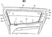
- FIG. 2 is an explanatory view showing the door as viewed from above the passenger compartment.
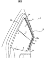
- FIG. 3 is an explanatory view showing the door as seen from the lower front side of the vehicle.
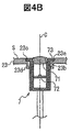
- FIG. 4A is a cross-sectional view showing a vertical cross section of the door at a position including the camera.
- FIG. 4B is an enlarged view showing the installation location of the camera in FIG. 4A.
- FIG. 5 is an explanatory diagram schematically illustrating an example of a detection surface. 6 is an explanatory diagram showing the detection surface of FIG. 5 as viewed from above.
- FIG. 7 is an explanatory view showing the installation position of the camera.
- FIG. 1 is an explanatory view showing a vehicle window glass lifting apparatus according to an embodiment of the present invention.
- FIG. 2 is an explanatory view showing the door as viewed from above the passenger compartment.
- FIG. 3 is an explanatory view
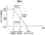
- FIG. 8A is a time chart showing the relationship between the detection of a foreign object and the operating speed of the window glass when the foreign object enters while the window glass is rising.
- FIG. 8B is a time chart showing the relationship between the detection of foreign matter and the operating speed of the window glass when the foreign matter enters while the window glass is rising.
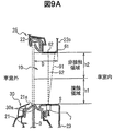
- FIG. 9A is a cross-sectional view showing a vertical cross section of a door at a position including a camera in a vehicle window glass lifting apparatus according to a modification of the present invention.
- FIG. 9B is an explanatory diagram schematically showing the detection surface of FIG. 9A.
- FIG. 10 is an explanatory view showing a vehicle window glass lifting apparatus according to another modification of the present invention.
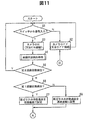
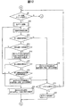
- FIG. 11 is a flowchart showing a control flow of the vehicle window glass lifting apparatus according to the embodiment and the modification.
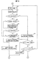
- FIG. 12 is a flowchart showing a control flow of the vehicle window glass lifting apparatus according to the embodiment and the modification.
- FIG. 13 is a flowchart showing a control flow of the vehicle window glass lifting apparatus according to the embodiment and the modification.
- FIG. 1 is an explanatory view showing a vehicle window glass lifting apparatus according to the present embodiment.
- a vehicle door (vehicle door) 2 on which a vehicle window glass elevating device 1 is mounted includes a storage portion 21 for storing a window glass 3 and a frame provided above the storage portion 21. Part 22.
- a door trim 23 is attached to the interior of the storage unit 21 so as to cover the storage unit 21.
- the frame portion 22 includes a rear standing portion 22a extending upward from the rear end portion of the storage portion 21 in the front-rear direction of the vehicle, and a front standing portion extending upward from the storage portion 21 on the front side of the rear standing portion 22a. 22b and an upward extending portion 22c extending from the upper end portion of the rear standing portion 22a to the upper end portion of the front standing portion 22b.
- the window glass 3 is fully closed, the window glass 3 is disposed in a space surrounded by the frame portion 22 and the upper end portion of the door trim 23. That is, the frame portion 22 and the upper end portion of the door trim 23 constitute the window frame 25.
- the window frame 25 refers to a portion in contact with the outer edge of the window glass 3 in a state where the door 2 and the window glass 3 are closed.
- the vehicle window glass elevating apparatus 1 includes a drive mechanism 4 that drives the window glass 3 and a control unit 5 that controls the drive mechanism 4.
- the drive mechanism 4 moves the window glass 3 in the vertical direction with respect to the window frame 25, and converts the motor 41 such as a DC motor and the driving force of the motor 41 into the vertical movement force of the window glass 3.
- a power conversion mechanism 42 includes, for example, a carrier plate that supports the window glass 3 and slides along the guide rail, and is attached to the wire by sliding the wire along the guide rail by the driving force of the motor 41.
- a window regulator or the like that moves the carrier plate and the window glass 3 in the vertical direction along the guide rail can be used.
- an X-arm type regulator or another type can be used as the power conversion mechanism 42.
- the door 2 is provided with a switch (SW) 24 for raising and lowering the window glass 3.
- An output signal line of the switch 24 is connected to the control unit 5.
- the switch 24 is composed of, for example, a two-stage click type swing switch. When one end of the descending side is clicked by one stage, the descending first stage click signal is clicked, and one end of the descending side is clicked by two stages. When the second side click signal of the descending side is clicked, the first side click signal of the rising side when the other end side that is the rising side is clicked by one step, and when the other end side that is the rising side is clicked by two steps
- the side second stage click signal is configured to be output to the control unit 5.
- the control unit 5 controls the drive mechanism 4 in accordance with a signal from the switch 24 and moves the window glass 3 in the vertical direction.
- the control unit 5 is mounted on the door 2 as a control unit in which a CPU, a memory, an interface, software, and the like are appropriately combined.
- the control unit 5 may be mounted as a function in an electronic control unit (ECU) that controls, for example, a vehicle mirror or a seat other than the door 2.
- ECU electronice control unit
- the control unit 5 descends the window glass 3 while the signal is input, and the descending second step click signal is input.
- the drive mechanism 4 is controlled so that the window glass 3 is automatically lowered until the window glass 3 is lowered to the lowest position or the switch 24 is operated again.
- the control unit 5 ascends the window glass 3 while the signal is input, and the ascending side second stage click signal is input.
- the drive mechanism 4 is controlled so that the window glass 3 is automatically raised until the window glass 3 is raised to the top or the switch 24 is operated again.
- the vehicle window glass elevating device 1 images a detection line 6 provided on the vehicle interior side of the window glass 3 along at least a part of the outer edge of the window glass 3 in a state where the door 2 and the window glass 3 are closed.
- a camera 7 is provided. In the present embodiment, based on the image captured by the camera 7, it is determined whether there is a foreign object that may be caught by the window glass 3. The specific configuration and mounting position of the camera 7 will be described later.
- the detection line 6 serves as a reference for determining whether there is a foreign object that may be caught by the window glass 3, and is set closer to the vehicle interior than the window glass 3. The specific configuration and setting position of the detection line 6 will be described later.
- a light source 8 that irradiates infrared light toward the detection line 6 is further provided.
- the camera 7 is composed of an infrared camera that captures infrared light that is irradiated from the light source 8 and reflected by the detection line 6.
- the control unit 5 includes a detection unit 51 that detects a shielding state in which at least a part of the detection line 6 captured by the camera 7 is shielded by a foreign substance, and a shielding state that is detected by the detection unit 51 when the window glass 3 is moved by the drive mechanism 4. And a pinching prevention unit 52 that causes the drive mechanism 4 to perform a pinching prevention operation for preventing pinching by the window glass 3.
- the detection unit 51 is an aspect of the detection means of the present invention
- the pinching prevention unit 52 is an aspect of the pinching prevention means of the present invention. Specific control contents of the detection unit 51 and the pinch prevention unit 52 will be described later.
- FIG. 2 is an explanatory view showing the door 2 as viewed from above the passenger compartment side
- FIG. 3 is an explanatory view showing the door 2 as seen from below the front side of the vehicle
- FIG. 4A is a position including the camera 7.
- Sectional drawing which shows the vertical direction cross section of a door
- FIG. 4B is an enlarged view which shows the installation location of the camera in FIG. 4A.
- the camera 7 forms an object image by the optical system 71 including at least one lens and the optical system 71.
- the optical system 71 is disposed at a position corresponding to the opening 23a formed on the upper surface S of the door trim 23 so that the optical axis C of the optical system 71 passes through the opening 23a. Yes.
- the camera 7 is provided on the upper surface S of the door trim 23.
- the upper surface S of the door trim 23 is an outer surface at the upper end portion of the door trim 23, and is a surface that is visible from above in the vertical direction.
- the upper surface S of the door trim 23 may be inclined with respect to the vehicle width direction (horizontal direction).
- the position of the upper surface S of the door trim 23 is highest in the vicinity of the window glass 3, that is, in the vicinity of the outlet 21 a from which the window glass 3 is led out from the storage portion 21, and becomes lower as the distance from the window glass 3 increases. It is formed to be curved. Therefore, it can be said that the upper surface S of the door trim 23 is the outer surface (portion corresponding to the lower inner peripheral surface of the window frame 25) of the door trim 23 in the vicinity of the window glass 3 (outlet port 21a).
- the opening 23a is formed on the vehicle interior side with respect to the outlet 21a, and the optical system 71 of the camera 7 is disposed so that the optical axis C is located on the vehicle interior side of the outlet 21a.
- the camera 7 is arranged so that the optical axis C of the optical system 71 coincides with the vertical direction, but the optical axis C of the optical system 71 is the longitudinal direction of the vehicle with respect to the vertical direction. Or may be inclined in the vehicle width direction, and may be appropriately adjusted according to the mounting position of the camera 7 or a desired imaging range.
- the camera 7 is disposed in a hole 23 b provided at a front position of the vehicle on the upper surface S of the door trim 23 (a front position on the upper surface S of the door trim 23 facing the window glass 3).
- a hole 23 b provided at a front position of the vehicle on the upper surface S of the door trim 23 (a front position on the upper surface S of the door trim 23 facing the window glass 3).
- the camera 7 is provided on the upper surface S of the door trim 23.
- the position where the camera 7 is installed is not limited to this.
- the camera 7 may be installed on the inner peripheral surface of the frame portion 22 or may be installed on the ceiling in the vehicle interior.
- the inner peripheral surface of the frame portion 22 is a surface facing the window glass 3 of the frame portion 22, and is a surface on the front side of the vehicle in the rear standing portion 22a and a surface on the rear side of the vehicle in the front standing portion 22b. This is the lower surface of the upper extension 22c. That is, the inner peripheral surface of the frame portion 22 is a portion near the window glass 3 in the outer peripheral surface of the frame portion 22. Details of the position where the camera 7 is installed will be described later.
- the camera 7 is formed in a columnar shape as a whole, and a flange 73 protruding outward in the radial direction is formed at the tip of the camera 7.
- the camera 7 is inserted into the hole 23b from above the door trim 23, the flange 73 is accommodated in a recess 23c formed at the periphery of the hole 23b, and the locking claw 23d provided at the periphery below the hole 23b is inserted into the camera. 7 is fixed to the door trim 23 by engaging with a groove (not shown) provided on the door 7.
- the front end surface of the camera 7 may protrude upwards from the upper surface S of the door trim 23, It may be located below the upper surface S of the door trim 23.
- the camera 7 is arranged so that a part of the optical system 71 is located above the opening 23a.
- the camera 7 may be arranged so that the optical system 71 is located below the opening 23a. I do not care.
- the structure for fixing the camera 7 to the door trim 23 and the insertion direction of the camera 7 are not particularly limited and can be changed as appropriate.
- the camera 7 is preferably configured such that the imaging range (viewing angle) covers the entire moving region of the window glass 3. Specifically, when the window glass 3 is completely retracted, the camera 7 has a viewing angle from the upper side in the vertical direction to the lower end of the rear standing portion 22a on the rear side of the vehicle. On the front side, it is desirable to set so as to cover the range from the upper side in the vertical direction to the lower end of the front standing portion 22b. When the window glass 3 is not completely retracted, the camera 7 has a viewing angle of the upper end (upper edge) and the rear of the window glass 3 when the window glass 3 is moved from the upper side in the vertical direction to the lowest position.
- the optical system 71 of the camera 7 it is desirable to use a wide-angle lens so that foreign matter can be detected in the above-described range.
- a super wide-angle lens having a combination of a plurality of lenses, a viewing angle of 180 ° or more in the vehicle front-rear direction, and a mounting angle of 190 ° is used.
- CMOS Complementary MOS
- the detection line 6 is set to be closer to the window glass 3 at least in the vehicle width direction than the first detection line 61 and the first detection line 61.
- 2 detection lines 62 are formed along at least a part of the outer edge of the window glass 3 in a state where the door 2 and the window glass 3 are closed.
- both detection lines 61 and 62 are set so as to extend along the entire frame portion 22 and away from the window glass 3 toward the vehicle interior side.
- the double detection lines 61 and 62 are formed in the vehicle width direction.
- the detection lines 61 and 62 only need to be set along the window frame 25, and may be set on the door 2 side or may be set on the vehicle body side.
- the second detection line 62 is set on the door 2 side and the first detection is performed.
- the line 61 may be set on the vehicle body side.
- the detection lines 61 and 62 may not be continuous, a part thereof may be set on the door 2 side, and a part thereof may be set on the vehicle body side.
- both detection lines 61 and 62 are set on the door 2 side.
- both the detection lines 61 and 62 are provided on the inner peripheral surface of the entire frame portion 22, that is, on the entire inner peripheral surface of the rear standing portion 22a, the front standing portion 22b, and the upper extending portion 22c. Is set to be separated from the vehicle interior side.
- the light source 8 is configured to irradiate the entire detection lines 61 and 62.
- the four light sources 8 are used to irradiate the detection lines 61 and 62 set on the entire inner peripheral surface of the frame portion 22 with infrared rays, but the number of the light sources 8 is limited to this. It is not something.
- the light source 8 is arranged on the upper surface S of the door trim 23 in the vicinity of the camera 7, but the arrangement of the light source 8 is not limited to this.
- the light source 8 is arranged on the inner peripheral surface of the frame portion 22. Also good.
- Both detection lines 61 and 62 are configured to have a luminance different from that of surrounding members when irradiated with infrared light.
- the boundary between them ie, the boundary between the door 2 and the vehicle body
- the inner peripheral surface of the frame portion 22 is made of a resin, an unevenness is provided in a part of the resin to form a line having infrared reflectance different from that of the surrounding area. It can also be used as 62.
- the present invention is not limited to this, and the detection lines 61 and 62 may be configured by applying a paint having a high infrared reflectance on the inner peripheral surface of the frame portion 22. You may be comprised from a different existing member. The same applies when the detection lines 61 and 62 are set on the vehicle body side.
- a pinching prevention operation is performed. This is to prevent a part of a human body such as a finger from being caught in the outlet 21a when the window glass 3 is lowered.
- a weather strip 30 having a lip seal 30a that is in sliding contact with the window glass 3 is provided around the outlet 21a in order to prevent water and the like from entering the storage portion 21 (internal space of the door 2).
- the pinching prevention operation that is performed when the shielding state is detected while the window glass 3 is lowered does not include the operation of lowering the window glass 3.
- FIG. 5 shows the first detection surface 91 and the second detection surface 92 formed in the present embodiment. As shown in FIG. 5, in this embodiment, double detection surfaces 91 and 92 are formed in the vehicle width direction.
- the detection surfaces 91 and 92 depend on the center of the optical system 71 (the center in the vehicle width direction, the height direction, and the vehicle front-rear direction) and the detection lines 61 and 62, depending on the specific structure of the optical system 71. Each surface is almost equal to the connecting surface.
- the detection surfaces 91 and 92 do not have to be continuous as a whole. For example, when the detection lines 61 and 62 are not continuous, the detection surfaces 91.92 are constituted by a plurality of surfaces. become.
- a line in which the positions that are in a shielding state when a foreign object is arranged between the optical system 71 of the camera 7 and the detection lines 61 and 62 are continuous is also a detection surface. 91, 92.
- the detection surfaces 91 and 92 are constituted by a plurality of surfaces or lines, in order to ensure safety, the interval between adjacent surfaces or lines may be at least the thickness of an infant's finger (for example, 4 mm). desirable.
- control contents of the control unit 5 including the detection unit 51 and the pinching prevention unit 52 will be described.
- the detection unit 51 includes at least a first shielding state in which at least a part of the first detection line 61 is shielded by foreign matter, and a second state in which at least a part of the second detection line 62 is shielded by foreign matter. It is configured to detect a shielding state.
- the detection unit 51 performs image processing of an image captured by the camera 7, extracts an image processing unit 51a that extracts both detection lines 61 and 62, and an image subjected to image processing by the image processing unit 51a. Based on this, at least a part of the first detection line 61 is in the first shielding state shielded by the foreign matter, and at least a part of the second detection line 62 is in the second shielding state shielded by the foreign matter. And a shielding state determination unit 51b for determining whether or not
- a specific method for extracting the detection lines 61 and 62 in the image processing unit 51a is not particularly limited. For example, an image captured by the camera 7 is trimmed to remove unnecessary portions, posterization processing or binary processing is performed. By performing the conversion process or the edge detection process, it is possible to extract the detection lines 61 and 62 having a luminance different from that of the surrounding members.
- the shielding state determination unit 51b for example, an image in a state where the first shielding state and the second shielding state are not established (an image after image processing by the image processing unit 51a) is stored in advance as an initial state image.
- the shielding state determination unit 51b compares the initial state image with the image output from the image processing unit 51a, and the difference between the extracted edges of the detection lines 61 and 62 and the difference between the areas of the detection lines 61 and 62 are detected. When a preset foreign matter determination threshold is exceeded, the first shielding state or the second shielding state is determined.
- the pinching prevention unit 52 controls the drive mechanism 4 to reduce the operating speed (movement speed) of the window glass 3 when the first shielding state is detected while the window glass 3 is moving.
- the driving mechanism 4 is configured to perform the pinching prevention operation.
- the window glass 3 By comprising in this way, it becomes possible to reduce the operating speed of the window glass 3 beforehand until the 2nd shielding state is detected, and the 2nd detection line 62 (2nd detection surface 92) is made more. Even if it is set near the window glass 3, the window glass 3 can be stopped or reversed before the invading foreign object contacts the window glass 3.
- the window glass 3 can be moved (however, if the first shielding state is detected, the operation of the window glass 3). Speed will be low).
- both detection lines 61 and 62 are formed on the inner peripheral surface of the entire frame portion 22, the first shielding state is always detected when the second shielding state is detected.
- an operation of stopping the movement of the window glass 3 an operation of lowering the window glass 3 to a safe position, This includes an operation of warning the operator by sound and light from an alarm device installed in the passenger compartment, and an operation combining these.
- the window glass 3 is as short as possible. It is necessary to quickly reduce the operating speed of the.
- the pinching prevention unit 52 is configured to output a command to stop the window glass 3.
- the pinching prevention unit 52 maintains the command and stops or lowers the movement of the window glass 3 to detect the first shielding state.
- the second shielding state is not detected for a predetermined time after the window glass 3 is operated at a lower speed (referred to as a low speed) than the normal operating speed (referred to as a normal speed) when the first shielding state and the second shielding state are not detected. It is comprised so that the drive mechanism 4 may be controlled to move.
- the “predetermined time” is less than the time required for the window glass 3 to actually stop or descend after the command to stop or lower the window glass 3 is output to the drive mechanism 4, and more preferably to the drive mechanism 4. It is set to be equal to or less than the time from when a command to stop or lower the window glass 3 is output until the operating speed of the window glass 3 reaches a preset low speed.
- a command to stop or lower the window glass 3 is output at the stage where the first shielding state is detected, but the window glass 3 is not stopped or lowered at this stage, and the second Only when the shielding state is detected, the window glass 3 is stopped or lowered.
- the motor 41 of the drive mechanism 4 is normally controlled by PWM (Pulse Width Modulation) control or the like, and the operating speed of the window glass 3 is lowered by changing the pulse width (duty ratio) output to the motor 41.
- PWM Pulse Width Modulation
- a command for lowering the window glass 3 is output, a reverse voltage is applied to reversely rotate the motor 41, so that the operating speed of the window glass 3 can be further reduced.
- a command to stop the movement of the window glass 3 or to lower the window glass 3 to the drive mechanism 4 (lowering of the window glass 3).
- the command to stop the window glass 3 is output, but if the control content of the drive mechanism 4 can be changed, the drive mechanism 4 may be configured to perform dedicated control. Is possible. For example, when the first shielding state is detected, the drive mechanism 4 is configured to quickly decrease the operating speed of the window glass 3 by stopping the power supply to the motor 41 or applying a reverse voltage to the motor 41. May be configured.
- the drive mechanism 4 when the first shielding state is detected during the movement of the window glass 3, the drive mechanism 4 is instructed to stop the movement of the window glass 3 or to lower the window glass 3 (lowering of the window glass 3 The operation speed of the window glass 3 is reduced by outputting a command to stop the window glass 3 in the inside.
- the passenger is in the first shielding state by shaking his / her body.
- the motor 41 is repeatedly turned on and off, and the window glass 3 may behave unnaturally depending on the configuration of the drive mechanism 4. Therefore, when such an unnatural behavior of the window glass 3 is remarkable, when the first shielding state is detected during the movement of the window glass 3, the operating speed of the window glass 3 is set to the drive mechanism 4.
- the pinching prevention unit 52 may be configured to output a command for setting a low speed. Further, when the first shielding state is not detected after the first shielding state is detected, the operating speed of the window glass 3 is set to the low speed until a preset time elapses after the first shielding state is not detected. You may make it suppress the unnatural behavior of the window glass 3 by maintaining as it is.
- a low-speed movement control unit 53 is further provided for controlling the drive mechanism 4 so as to move the window glass 3 at a low speed.
- the movement of the window glass 3 can be started at a low speed when the first shielding state is detected.
- the first shielding state is not detected immediately after the window glass 3 starts moving at the normal speed and is controlled to the low speed, and the unnatural behavior of the window glass 3 is suppressed. Is possible.
- the low speed movement control unit 53 is an aspect of the low speed movement control unit means of the present invention.
- control unit 5 is configured such that when the second shielding state is detected by the detection unit 51 after the movement of the window glass 3 is instructed by the switch 24 and before the movement of the window glass 3 is started, An instruction invalidation unit 54 that invalidates the instruction is further provided.
- the instruction invalidation unit 54 is an aspect of the instruction invalidation unit of the present invention.
- an anti-pinch operation is performed before the foreign object contacts the window glass 3 (that is, the window glass 3 is stopped or reversed).
- the positions of the camera 7 and the detection lines 61 and 62 are determined so as to be possible.
- the assumed intrusion speed of the foreign matter, the reading speed of the camera 7, the calculation speed of the control unit 5 (the time from imaging until the judgment of the intrusion of foreign matter), and the movement of the window glass 3 of the drive mechanism 4 are stopped.
- the speed time for stopping the window glass 3
- the shortest distance the inner surface of the window glass 3 that can prevent the object from being caught before the foreign object comes into contact with the window glass 3 even if the foreign object enters. (Distance in the vehicle width direction from) is referred to as a safety ensuring distance.
- the distance d1 in the vehicle width direction between the first detection surface 91 and the inner surface of the window glass 3 is equal to or greater than the safety ensuring distance when the operating speed of the window glass 3 is set to the normal speed in the entire area of the first detection surface 91. .
- the 1st detection line 61 is formed in the position where the distance of the vehicle width direction from the inner surface of the window glass 3 becomes more than the safety ensuring distance when the operating speed of the window glass 3 is made into a normal speed.
- the camera 7 is disposed at a position where the distance in the vehicle width direction from the inner surface of the window glass 3 to the center of the optical system 71 is equal to or greater than the safety ensuring distance when the operation speed of the window glass 3 is set to the normal speed. .
- the case where the 1st detection line 61 and the camera 7 are provided in the position where the distance of the vehicle width direction from the inner surface of the window glass 3 becomes equal is demonstrated.
- the first detection surface 91 is formed in parallel with the window glass 3.
- the second detection surface 92 is set such that the minimum value of the distance d2 in the vehicle width direction from the inner surface of the window glass 3 is equal to or greater than the safety ensuring distance when the operating speed of the window glass 3 is set to the low speed.
- the second detection surface 92 since the camera 7 is disposed at the same position as the first detection line 6 in the vehicle width direction, the second detection surface 92 is closest to the window glass 3 in the vicinity of the second detection line 62. . Therefore, the second detection line 62 is formed at a position where the distance in the vehicle width direction from the inner surface of the window glass 3 is equal to or greater than the safety ensuring distance when the operating speed of the window glass 3 is set to the low speed.
- the minimum value of the distance d2 in the vehicle width direction from the inner surface of the glass 3 to the second detection surface 92 can be equal to or greater than the safety ensuring distance when the operating speed of the window glass 3 is set to the low speed.
- the distance between the second detection surface 92 and the first detection surface 91 at the position where the second detection surface 92 is closest to the window glass 3 is determined in consideration of an assumed entry speed of the foreign matter. The distance through which the operating speed of the window glass 3 can be reduced from the normal speed to the low speed from the detection surface 91 to the second detection surface 92 after the detection of the first shielding state is detected.
- the seat 81 on which the occupant rides is disposed below and behind the window glass 3, and the occupant leans against the door 2.
- a region A indicated by a one-dot chain line in FIG. 6, that is, a rear region A in the window frame 25 a part of the body such as a shoulder and a head of the passenger is likely to approach the window glass 3. Therefore, the second detection surface 92 is as close to the window glass 3 as possible in the rear region A in the window frame 25 so that the window glass 3 can be moved even when the passenger leans on the door 2. It can be said that it is desirable to set as follows.
- the second detection surface 92 is formed at a position away from the window glass 3 in the rear region of the vehicle.
- the camera 7 is arranged as close to the front side of the window frame 25 as possible and the camera 7 as close to the window glass 3 as possible. It is desirable to arrange.
- the camera 7 When the camera 7 is arranged on the vehicle interior side of the second detection line 62 as in the present embodiment, the camera 7 has at least a window, depending on the position of the vehicle seat 81, the physique of the passenger, and the like.
- the frame 25 be disposed ahead of the center of the window glass 3 in the front-rear direction of the vehicle. That is, the camera 7 is located at a position ahead of the center of the window glass 3 (the center in the vehicle front-rear direction) on the upper surface S of the door trim 23 or the lower side surface of the upper extending portion 22c, or behind the front standing portion 22b. It is desirable to arrange on the side surface.
- FIGS. 8A and 8B the relationship between the detection of foreign matter and the operating speed of the window glass when foreign matter enters while the window glass 3 is rising will be described with reference to FIGS. 8A and 8B.
- a command for stopping the window glass 3 is output to the drive mechanism 4 when the first shielding state is detected.
- 8A and 8B represents the operating speed of the window glass 3 in the upward direction.
- the operating speed of the window glass 3 is set to the normal speed in a state where the first shielding state and the second shielding state are not detected.
- the command (stop command) which stops the window glass 3 will be output, and the operating speed of the window glass 3 will fall.
- the entire movement region of the window glass 3 is a non-contact region in which a pinch prevention operation can be performed before the foreign material comes into contact with the window glass 3 even if the foreign material enters.
- the positions of the camera 7 and the detection lines 61 and 62 are determined.
- the present invention is not limited to this, and a lower partial region of the moving region of the window glass 3 may be used as a contact region.
- the area in the vicinity of the camera 7 is a contact area in which the foreign object may come into contact with the moving window glass 3 even if the pinch prevention operation is performed after the foreign object is detected.
- 9A and 9B show a case where the second detection line 62 and the camera 7 are provided at positions where the distance in the vehicle width direction from the inner surface of the window glass 3 becomes equal. In this case, if the distance in the vehicle width direction from the inner surface of the window glass 3 of the second detection line 62 is constant, the second detection surface 92 is formed in parallel with the window glass 3.
- the camera 7 is disposed in the area behind the window frame 25 (the above-described area A). However, it becomes possible to ensure sufficient convenience. That is, the degree of freedom of the installation position of the camera 7 is improved.
- the pinching by the window glass 3 is likely to occur in the vicinity of the dead end of the window frame 25, that is, in the upper area of the moving area of the window glass 3, and in this case, the contact area is formed as low as possible.
- the camera 7 is desirably disposed at least below the center in the height direction of the window glass 3 in the inner peripheral surface of the window frame 25.
- the height h2 of the non-contact area is as large as possible within a range where the convenience does not deteriorate, and it is desirable that the height h1 of the contact area be as small as possible. .
- the average value of head height of 3 years old child is 191mm
- the height h2 of the non-contact area be at least 200 mm.
- the first detection line 61 is imaged by one camera (referred to as a first camera) 7a
- the second detection line 62 is imaged by the other camera (referred to as a second camera) 7b.
- the detection unit 5 is configured to detect the first shielding state based on the image captured by the first camera 7a and detect the second shielding state based on the image captured by the second camera 7b.
- the first camera 7a is disposed at the same position as the first detection line 61 in the vehicle width direction
- the second camera 7b is disposed at the same position as the second detection line 62 in the vehicle width direction.
- 91 and 92 can be formed parallel to the window glass 3, and safety and convenience can be ensured regardless of the position of the camera 7 placed on the inner peripheral surface of the window frame 25. It becomes possible.
- the camera 7 can be arranged not only on the inner peripheral surface of the window frame 7 but also in any position in the vehicle interior.
- step S ⁇ b> 1 the control unit 5 determines whether a signal is input from the switch 24. If NO is determined in step S1, the control unit 5 turns off the power of the camera 7 (or continues the power-off state) in step S2, and returns to step S1. Although not shown, when the light source 8 is turned on, the light source 8 is turned off in step S2.
- step S1 If YES is determined in step S1, the control unit 5 turns on the power of the camera 7 (or continues the power-on state) in step S3, and proceeds to step S4. Although illustration is omitted here, when the illuminance for imaging with the camera 7 is insufficient, the power source of the light source 8 is turned on in step S3.
- step S4 the detection unit 51 (the image processing unit 51a and the shielding state determination unit 51b) detects the first shielding state and the second shielding state based on the image captured by the camera 7 (shielding state detection processing). I do. Thereafter, in step S ⁇ b> 5, the instruction invalidation unit 54 determines whether the second shielding state is detected by the detection unit 51.
- step S5 the instruction invalidation unit 54 determines that there is a possibility of being caught by the window glass 3, and does not move the window glass 3 (that is, invalidates the signal from the switch 24). Return to S1.
- step S6 the low speed movement control unit 53 determines whether the first shielding state is detected in the shielding state detection process in step S4.
- step S6 the operating speed of the window glass 3 is set to a low speed in step S7, and the process proceeds to step S9 in FIG. If NO is determined in step S6, the operating speed of the window glass 3 is set to the normal speed in step S8, and the process proceeds to step S9 in FIG.
- step S ⁇ b> 9 the signal input from the switch 24 by the control unit 5 is the first-stage click signal (the descending-side first-stage click signal or the ascending-side first-stage click signal). Determine whether.
- step S9 determines whether the second-stage click signal (the descending-side second-stage click signal or the ascending-side second-stage click signal) is input from the switch 24, the process proceeds to step S22 in FIG. move on.
- step S10 the control unit 5 controls the drive mechanism 4 to perform movement control of the window glass 3 at the set operating speed.
- step S ⁇ b> 11 the detection unit 51 performs processing for detecting the first shielding state and the second shielding state (shielding state detection processing) based on the image captured by the camera 7. Thereafter, in step S ⁇ b> 12, the pinching prevention unit 52 determines whether the first shielding state is detected by the detection unit 51.
- step S12 If it is determined NO in step S12, the first shielding state is not detected, and it is considered that no foreign matter has entered the vicinity of the window glass 3. Therefore, the operating speed of the window glass 3 is determined in step S18. Is set to normal speed (or continued), and the process proceeds to step S19.
- step S13 the pinching prevention unit 52 determines whether the operating speed of the window glass 3 is set to a low speed. If it is determined as YES in step S13, it is not necessary to perform control for reducing the operating speed of the window glass 3, and the process proceeds to step S15.
- step S14 the pinching prevention unit 52 outputs a command to stop or reverse the window glass 3 to the drive mechanism 4 in order to reduce the operating speed of the window glass 3.
- the process proceeds to step S15.
- step S14 when the window glass 3 is lowered, a command to stop the window glass 3 is output.
- step S15 the pinching prevention unit 52 determines whether the second shielding state is detected in the shielding state detection process in step S11. If YES is determined in step S15, the pinch prevention operation is executed (or the instruction in step S14 is maintained) in step S21, and the process returns to step S2 in FIG.
- step S16 the pinching prevention unit 52 determines whether a predetermined time has elapsed after the first shielding state is detected. If NO is determined in step S16, it is considered that the operating speed of the window glass 3 is already low, or that the window glass 3 is being decelerated by outputting a command to stop or reverse the window glass 3. Therefore, the process returns to step S11 to continue the shielding state detection process.
- step S16 If YES is determined in step S16, the operating speed of the window glass 3 is set (or continued) at a low speed in step S17, and then the process proceeds to step S19.
- step S ⁇ b> 19 the control unit 5 determines whether a signal is input from the switch 24. When it is determined NO in step S19, the operation of the switch 24 is completed. Therefore, after the control unit 5 finishes moving the window glass 3 in step S20, the process returns to step S2 in FIG. If YES is determined in step S19, the process returns to step S9 to continue the movement of the window glass 3.
- step S ⁇ b> 22 the control unit 5 controls the drive mechanism 4 to perform movement control of the window glass 3 at the set operation speed.
- step S ⁇ b> 23 the detection unit 51 performs processing for detecting the first shielding state and the second shielding state (shielding state detection processing) based on the image captured by the camera 7. Thereafter, in step S24, the pinching prevention unit 52 determines whether the detection unit 51 has detected the first shielding state.
- step S24 When it is determined NO in step S24, the first shielding state is not detected, and it is considered that no foreign matter has entered the vicinity of the window glass 3. Therefore, the operating speed of the window glass 3 is determined in step S30. Is set to normal speed (or continued), and the process proceeds to step S31.
- step S24 the pinch prevention unit 52 determines whether the operating speed of the window glass 3 is set to a low speed in step S25. If it is determined as YES in step S25, it is not necessary to perform control for reducing the operating speed of the window glass 3, and the process proceeds to step S27.
- step S26 the pinching prevention unit 52 outputs a command to stop or reverse the window glass 3 to the drive mechanism 4 in order to reduce the operating speed of the window glass 3.
- the process proceeds to step S27.
- step S26 when the window glass 3 is being lowered, a command to stop the window glass 3 is output.
- step S27 the pinching prevention unit 52 determines whether the second shielding state is detected in the shielding state detection process in step S23. If YES is determined in step S27, the pinch prevention operation is executed (or the instruction in step S26 is maintained) in step S34, and the process returns to step S2 in FIG.
- step S28 the pinching prevention unit 52 determines whether a predetermined time has elapsed since the first shielding state was detected.
- step S28 If YES is determined in step S28, the operating speed of the window glass 3 is set (or continued) to a low speed in step S29, and then the process proceeds to step S31.
- step S31 the control part 5 judges whether the window glass 3 was moved to the end (to the position of an upper end or a lower end). If YES is determined in step S31, the control unit 5 returns to step S2 in FIG. 11 after the control unit 5 finishes moving the window glass 3 in step S32.
- the position information of the window glass 3 may be acquired by using a rotation pulse generated by using a Hall IC incorporated in the motor 41 or a current ripple.
- step S33 it is determined in step S33 whether a new signal is input from the switch 24 (whether a new signal is input after the second-stage click signal is input). If YES is determined in the step S33, the process returns to the step S9 in FIG. When it is judged as NO at Step S33, it returns to Step S22 and continues movement of window glass 3. That is, when the second stage click signal is input, the second glass state is detected until the second shielding state is detected, the window glass 3 moves to the end, or a new signal is input from the switch 24. Continue moving.
- the first detection line 61 and the second detection window 61 set closer to the window glass 3 in the vehicle width direction than the first detection line 61.
- the detection unit 51 includes a first shielding state in which at least a part of the first detection line 61 is shielded by foreign matter, and at least a part of the second detection line 62 is shielded by foreign matter.
- the sandwiching prevention unit 52 is configured to detect the second shielding state, and when the first shielding state is detected during the movement of the window glass 3, the drive mechanism 4 controls to reduce the operating speed of the window glass 3. When the second shielding state is detected, the drive mechanism 4 is configured to perform the pinching prevention operation.
- the second detection line 62 (second detection surface 92) serving as a reference for performing the pinching prevention operation is more window glass than the case where only one detection line (detection surface) is provided. Even if it is set near 3, sufficient safety can be secured. As a result, for example, even when the passenger is leaning against the door 2, if the second shielding state is not detected and there is no possibility of being caught by the window glass 3, the window glass 3 is at least at a low speed. Can be moved, and convenience can be improved.
- the pinch prevention operation is performed in spite of the possibility of being pinched by the window glass 3 while ensuring sufficient safety, and the window glass 3 can be moved when desired. It is possible to improve the convenience by suppressing problems such as absence.
- a camera (7) for imaging wherein the control unit (5) detects a shielding state in which at least a part of the detection line (6) imaged by the camera (7) is shielded by a foreign object
- the detection line (6) is at least a vehicle width wider than the first detection line (61) and the first detection line (61).
- the pinching prevention means (52) stops the movement of the window glass (3) or detects the window glass (3) when the first shielding state is detected while the window glass (3) is raised.
- Command to lower the window glass (3) is output to the drive mechanism (4), and when the first shielding state is detected while the window glass (3) is being lowered, the command to stop the movement of the window glass (3)
- the drive mechanism (4) By outputting to the drive mechanism (4), the operating speed of the window glass (3) is reduced, and when the second shielding state is detected within a predetermined time after the detection of the first shielding state, the command is issued.
- the vehicle window glass elevating device (1) configured to control the drive mechanism (4) so as to move at a lower speed than a normal operation speed where a shielding state is not detected. ).
- the controller (5) is configured to detect the first shielding by the detecting means (51) after the movement of the window glass (3) is instructed and before the movement of the window glass (3) is started. When the state is detected and the second shielding state is not detected, the window glass (3) is moved at a lower speed than the normal operating speed when the first shielding state and the second shielding state are not detected.
- the vehicle window glass elevating and lowering device (1) according to [1] or [2], further comprising low-speed movement control means (53) for controlling the drive mechanism (4).
- the present invention is not limited to this.
- the number of detection lines 6 (the number of detection surfaces) is set to three or more, and the operation speed of the window glass 3 is gradually reduced as a foreign object approaches the window glass 3 side from the vehicle interior side. It doesn't matter.
- the window The operating speed of the glass 3 is reduced to a first low speed lower than the normal speed, and when the first shielding state is detected, the operating speed of the window glass 3 is reduced to a second low speed lower than the first low speed.
- the vehicle window glass elevating device 1 may be configured to perform the pinching prevention operation when the second shielding state is detected.
- the vehicle window glass elevating device 1 monitors the rotation speed of the motor 41, and the load increases while the window glass 3 is raised, and the rotation speed of the motor 41 decreases. Sometimes, it is determined that a foreign object has been caught by the window glass, and a safety device that performs various safety operations such as reversing the moving direction of the window glass 3 and automatically lowering the window glass 3 may be provided.
- the present invention can be applied to a vehicle window glass lifting apparatus provided with a mechanism that prevents the window glass from being caught when the window glass automatically moves.
- Vehicle window glass lifting device 2 Door (vehicle door) 3 Window Glass 4 Drive Device 5 Control Unit 6 Detection Line 7 Camera 25 Window Frame 51 Detection Unit (Detection Means) 52 Anti-pinch part (Pinch prevention means) 53 Low-speed movement control unit (low-speed movement control means) 54 Instruction invalid part (instruction invalidating means) 61 1st detection line 62 2nd detection line 91 1st detection surface 92 2nd detection surface
Landscapes
- Power-Operated Mechanisms For Wings (AREA)
- Window Of Vehicle (AREA)
Abstract
This window glass lifting device for a vehicle comprises a drive mechanism 4 which moves a window glass 3, a control unit 5 which controls the drive mechanism 4, and a camera 7 which images a detection line 6 which is disposed along the outer edge of the window glass 3 in a state in which the door 2 and the window glass 3 are closed. The detection line 6 comprises a first detection line 61 and a second detection line 62 which is nearer to the window glass 3 than the first detection line 61. The control unit 5 comprises a detection unit 51 which detects the first blocked state and a second blocked state, and a pinch prevention unit 52 which, during movement of the window glass 3, if the first blocked state has been detected, lowers the operation speed of the window glass 3 and, if the second blocked state has been detected, controls the drive mechanism 4 so as to prevent pinching by the window glass 3.
Description
本発明は、車両用窓ガラス昇降装置及び車両に関する。
The present invention relates to a vehicle window glass elevating device and a vehicle.
近年、車両には、窓ガラスの開閉操作を容易とするため、窓ガラスを自動で昇降させる車両用窓ガラス昇降装置が搭載されている。
2. Description of the Related Art In recent years, vehicles have been equipped with a vehicle window glass lifting device that automatically lifts and lowers the window glass in order to facilitate opening and closing the window glass.
車両用窓ガラス昇降装置は、車両のドアに配置され窓ガラスを上下方向に移動させる駆動機構と、駆動機構を制御する制御部と、を備えて構成されている。
The vehicle window glass elevating device includes a drive mechanism that is arranged on a door of a vehicle and moves the window glass in the vertical direction, and a control unit that controls the drive mechanism.
車両用窓ガラス昇降装置では、窓ガラスを電動で昇降させるために、窓ガラスによる挟み込みを防止する機構が設けられるのが一般的である。
In a vehicle window glass elevating device, a mechanism for preventing the window glass from being caught is generally provided in order to elevate and lower the window glass electrically.
このような機構として、窓ガラスを駆動するモータの回転数の変化を監視し、窓ガラスの上昇中に負荷が増加しモータの回転数が減少したときに、窓ガラスによる異物の挟み込みが発生したと判定し、窓ガラスの移動方向を反転させ自動で下降させる等の各種安全動作を行わせるものが知られている。
As such a mechanism, the change in the rotation speed of the motor driving the window glass is monitored, and when the load increases while the window glass is rising and the rotation speed of the motor decreases, the foreign object is caught by the window glass. It is determined that, and various safety operations such as reversing the moving direction of the window glass and automatically lowering the window glass are performed.
しかし、このような機構では、実際に異物(人体の一部等)が挟まれた後に安全動作が行われるので、人体に荷重が加わってしまうという観点から、安全性に対して問題があった。例えば、このような機構では、窓ガラスの締切を挟み込みと誤検知しないように窓ガラスの締切端から例えば4mmの領域が不感帯となっていることが多く、例えば、幼児の指が挟まれた際には安全動作が行われないおそれもあり、改善が望まれていた。
However, in such a mechanism, since a safe operation is performed after a foreign object (a part of the human body or the like) is actually sandwiched, there is a problem with safety from the viewpoint that a load is applied to the human body. . For example, in such a mechanism, an area of, for example, 4 mm from the window glass cut-off edge is often a dead zone so that the window glass cut-off is not erroneously detected as being pinched. For example, when an infant's finger is pinched, In some cases, there was a risk that safe operation would not be performed, and an improvement was desired.
このような問題を解決した車両用窓ガラス昇降装置として、特許文献1がある。
There exists patent document 1 as a window glass raising / lowering device for vehicles which solved such a problem.
特許文献1では、窓ガラスよりも車室内側で、かつ、窓ガラスよりも車両の前方側の下方にカメラを設置し、当該カメラにより撮像した画像を基に、窓ガラスによる挟み込みのおそれがある異物を検出し、窓ガラスを自動で下降させる等の各種安全動作を行わせる点が記載されている。
In Patent Document 1, a camera is installed on the vehicle interior side with respect to the window glass and below the front side of the vehicle with respect to the window glass, and there is a risk of being pinched by the window glass based on an image captured by the camera. It describes that foreign objects are detected and various safety operations such as automatically lowering the window glass are performed.
また、特許文献1では、窓枠周辺に塗布したマーカや窓枠の輪郭のエッジ等を異物判定用の特徴量として用い、特徴量として用いるマーカ等とカメラとの間に異物が介在したときに、各種安全動作を行わせる点が記載されている。
Moreover, in patent document 1, when the marker applied to the periphery of a window frame, the edge of the outline of a window frame, etc. is used as a feature quantity for a foreign substance determination, and a foreign substance intervenes between the marker etc. used as a feature quantity and a camera It describes that various safety operations are performed.
特許文献1のように、カメラで撮像した画像から窓ガラスに挟み込まれる可能性のある異物を検出することで、挟み込みが発生する前に安全動作を行わせることが可能になり、安全性がより向上する。
As in Patent Document 1, by detecting a foreign object that may be caught in the window glass from an image captured by a camera, it is possible to perform a safe operation before the occurrence of the pinching, and the safety is further improved. improves.
車両では、シート位置や搭乗者の体格や搭乗者の姿勢(例えば搭乗者がドアに寄り掛かっている場合等)によっては、通常の使用であっても搭乗者の体の一部が窓ガラスの近く、すなわちカメラとマーカ等の間に位置してしまうこととなり、実際には窓ガラスが上昇作動している際、窓ガラスによる挟み込みのおそれがないにもかかわらず、窓ガラスを自動で下降させる、あるいは窓ガラスの移動を停止させる等の安全動作が行われてしまう場合がある。昇降操作時に窓ガラスを上昇もしくは下降させることができなくなる場合もある。このような場合、通常の使用の中で、窓ガラスを閉じたいときに閉じられない、あるいは、窓ガラスを動かしたいときに動かせないといったことになり、利便性が低下してしまう。
In vehicles, depending on the seat position, the occupant's physique and the occupant's posture (for example, when the occupant is leaning against the door), a part of the occupant's body may It will be located near, that is, between the camera and the marker, etc. When the window glass is actually moving up, the window glass is lowered automatically even though there is no risk of being caught by the window glass Or, a safe operation such as stopping the movement of the window glass may be performed. In some cases, the window glass cannot be raised or lowered during the raising / lowering operation. In such a case, during normal use, the window glass cannot be closed when it is desired to be closed, or cannot be moved when the window glass is desired to be moved, and convenience is reduced.
利便性を向上するために、窓ガラスの直近にカメラとマーカ等を設けることが考えられるが、この場合、窓ガラスの直近まで異物が侵入しないと当該異物を検出できなくなるため、異物の検出後に安全動作を行っても、窓ガラスの停止が間に合わずに異物が窓ガラスに挟み込まれるおそれがあり、安全性が低下するおそれがある。特に、ドアトリムの幅やサッシュ幅の小さい車両では、カメラやマーカ等を設ける位置が窓ガラスに近くなり、安全性が十分に確保できない場合も考えられる。
In order to improve convenience, it is conceivable to install a camera and a marker in the immediate vicinity of the window glass. However, in this case, if the foreign object does not enter the window glass, the foreign object cannot be detected. Even if the safe operation is performed, there is a possibility that foreign matter may be caught in the window glass without stopping the window glass in time, and safety may be lowered. In particular, in a vehicle having a small door trim width or sash width, a position where a camera, a marker, or the like is provided is close to the window glass, and there may be a case where sufficient safety cannot be secured.
さらに、搭乗者がドアに寄り掛かっている場合、搭乗者の頭部が窓ガラスの比較的上方の領域に近接してしまうことも考えられる。窓ガラスの上方の領域では窓ガラスによる挟み込みが発生しやすいために十分な安全性を確保する必要があるが、上述のような搭乗者がドアに寄り掛かっている場合にも、窓ガラスによる挟み込みのおそれがない場合には窓ガラスを移動可能として、安全性と利便性を両立することが望まれている。
Further, when the occupant is leaning against the door, the occupant's head may be close to a relatively upper region of the window glass. It is necessary to ensure sufficient safety in the area above the window glass because it is likely to be pinched by the window glass, but even when the above-mentioned passenger is leaning on the door, the window glass is pinched. When there is no fear, it is desired to make the window glass movable so that both safety and convenience can be achieved.
本発明の目的は、安全性を確保しつつも利便性を向上することが可能な車両用窓ガラス昇降装置及び車両を提供することにある。
An object of the present invention is to provide a vehicle window glass elevating device and a vehicle capable of improving convenience while ensuring safety.
本発明の一実施形態による車両用窓ガラス昇降装置は、車両のドアに配置され窓ガラスを上下方向に移動させる駆動機構と、前記駆動機構を制御する制御部と、前記ドア及び前記窓ガラスが閉まっている状態において前記窓ガラスの外縁の少なくとも一部に沿って前記窓ガラスよりも車室内側に設けられた検出ラインを撮像するカメラと、を備え、
前記制御部は、前記カメラによって撮像された前記検出ラインの少なくとも一部が異物によって遮蔽された遮蔽状態を検出する検出手段と、前記駆動機構による前記窓ガラスの移動時に前記検出手段によって前記遮蔽状態が検出されたとき、前記窓ガラスによる挟み込みを防止するための挟み込み防止動作を前記駆動機構に行わせる挟み込み防止手段とを有し、
前記検出ラインは、少なくとも、第1検出ラインと、前記第1検出ラインよりも車幅方向において前記窓ガラスと近接して設定された第2検出ラインと、を有し、
前記検出手段は、少なくとも、前記第1検出ラインの少なくとも一部が異物によって遮蔽された第1遮蔽状態と、前記第2検出ラインの少なくとも一部が異物によって遮蔽された第2遮蔽状態とを検出するように構成され、
前記挟み込み防止手段は、前記窓ガラスの移動中に前記第1遮蔽状態が検出されたとき、前記窓ガラスの作動速度を低下させる制御を前記駆動機構に行わせ、前記第2遮蔽状態が検出されたとき、前記挟み込み防止動作を前記駆動機構に行わせるように構成される。 A vehicle window glass lifting apparatus according to an embodiment of the present invention includes: a drive mechanism that is disposed on a vehicle door and moves the window glass in a vertical direction; a control unit that controls the drive mechanism; the door and the window glass. A camera that images a detection line provided on the vehicle interior side of the window glass along at least a part of the outer edge of the window glass in a closed state,
The control unit is configured to detect a shielding state in which at least a part of the detection line imaged by the camera is shielded by a foreign substance, and the shielding state by the detection unit when the window glass is moved by the driving mechanism. When it is detected, it has a pinching prevention means for causing the drive mechanism to perform a pinching prevention operation for preventing pinching by the window glass,
The detection line includes at least a first detection line and a second detection line set closer to the window glass in the vehicle width direction than the first detection line,
The detecting means detects at least a first shielding state in which at least a part of the first detection line is shielded by a foreign substance and a second shielding state in which at least a part of the second detection line is shielded by a foreign substance. Configured to
When the first shielding state is detected during the movement of the window glass, the pinching prevention means causes the drive mechanism to perform a control to reduce the operating speed of the window glass, and the second shielding state is detected. In this case, the drive mechanism is configured to perform the pinching prevention operation.
本発明の上記実施形態は、「検出ラインは、少なくとも、第1検出ラインと、第1検出ラインよりも車幅方向において窓ガラスと近接して設定された第2検出ラインと、を有し、検出手段は、少なくとも、第1検出ラインの少なくとも一部が異物によって遮蔽された第1遮蔽状態と、第2検出ラインの少なくとも一部が異物によって遮蔽された第2遮蔽状態とを検出するように構成され、挟み込み防止手段は、窓ガラスの移動中に第1遮蔽状態が検出されたとき、窓ガラスの作動速度を低下させる制御を駆動機構に行わせ、第2遮蔽状態が検出されたとき、挟み込み防止動作を駆動機構に行わせるように構成される」という構成を有する。
これにより、挟み込み防止動作を行う基準となる第2検出ラインをより窓ガラスに近い位置に設定することが可能になり、窓ガラスによる挟み込みのおそれがないにもかかわらず、挟み込み防止動作が行われてしまうといった不具合を抑制し、安全性を確保しつつも利便性を向上することが可能になる。その結果、搭乗者がドアに寄り掛かっている場合であっても、窓ガラスによる挟み込みのおそれがない場合には窓ガラスを移動可能として、安全性と利便性を両立することが可能になる。 The above-mentioned embodiment of the present invention is described as follows: “The detection line has at least a first detection line and a second detection line set closer to the window glass in the vehicle width direction than the first detection line, The detection means detects at least a first shielding state in which at least a part of the first detection line is shielded by a foreign substance and a second shielding state in which at least a part of the second detection line is shielded by the foreign substance. The sandwiching preventing means is configured such that when the first shielding state is detected during the movement of the window glass, the driving mechanism performs control to reduce the operating speed of the window glass, and when the second shielding state is detected, It is configured to cause the drive mechanism to perform the pinching prevention operation ”.
This makes it possible to set the second detection line as a reference for performing the pinching prevention operation at a position closer to the window glass, and the pinching prevention operation is performed even though there is no fear of pinching by the window glass. It is possible to improve the convenience while suppressing safety and ensuring safety. As a result, even when the passenger is leaning against the door, the window glass can be moved when there is no risk of being caught by the window glass, and both safety and convenience can be achieved.
また、本発明の他の実施形態による車両は、上記実施形態の車両用窓ガラス昇降装置を備える。
Moreover, the vehicle by other embodiment of this invention is equipped with the window glass raising / lowering apparatus for vehicles of the said embodiment.
本発明の一実施形態によれば、安全性を確保しつつも利便性を向上することが可能な車両用窓ガラス昇降装置及び車両を提供できる。
According to one embodiment of the present invention, it is possible to provide a vehicle window glass lifting apparatus and a vehicle that can improve convenience while ensuring safety.
[実施形態]
以下、本発明の実施形態を、図面を参照して説明する。 [Embodiment]
Embodiments of the present invention will be described below with reference to the drawings.
以下、本発明の実施形態を、図面を参照して説明する。 [Embodiment]
Embodiments of the present invention will be described below with reference to the drawings.
図1は、本実施形態に係る車両用窓ガラス昇降装置を示す説明図である。
FIG. 1 is an explanatory view showing a vehicle window glass lifting apparatus according to the present embodiment.
図1に示されるように、車両用窓ガラス昇降装置1を搭載する車両のドア(車両用ドア)2は、窓ガラス3を格納する格納部21と、格納部21の上方に設けられた枠部22と、を有している。格納部21の車室内側には、格納部21を覆うようにドアトリム23が取り付けられている。
As shown in FIG. 1, a vehicle door (vehicle door) 2 on which a vehicle window glass elevating device 1 is mounted includes a storage portion 21 for storing a window glass 3 and a frame provided above the storage portion 21. Part 22. A door trim 23 is attached to the interior of the storage unit 21 so as to cover the storage unit 21.
枠部22は、車両の前後方向における格納部21の後側の端部から上方に延びる後方立設部22aと、後方立設部22aよりも前側で格納部21から上方に延びる前方立設部22bと、後方立設部22aの上端部から前方立設部22bの上端部に至る上方延設部22cと、からなる。窓ガラス3の全閉時には、枠部22とドアトリム23の上端部とに囲まれた空間に、窓ガラス3が配置されることになる。つまり、枠部22とドアトリム23の上端部とが、窓枠25を構成している。本実施形態では、窓枠25とは、ドア2及び窓ガラス3が閉まっている状態で窓ガラス3の外縁に接する部分をいう。
The frame portion 22 includes a rear standing portion 22a extending upward from the rear end portion of the storage portion 21 in the front-rear direction of the vehicle, and a front standing portion extending upward from the storage portion 21 on the front side of the rear standing portion 22a. 22b and an upward extending portion 22c extending from the upper end portion of the rear standing portion 22a to the upper end portion of the front standing portion 22b. When the window glass 3 is fully closed, the window glass 3 is disposed in a space surrounded by the frame portion 22 and the upper end portion of the door trim 23. That is, the frame portion 22 and the upper end portion of the door trim 23 constitute the window frame 25. In the present embodiment, the window frame 25 refers to a portion in contact with the outer edge of the window glass 3 in a state where the door 2 and the window glass 3 are closed.
車両用窓ガラス昇降装置1は、窓ガラス3を駆動する駆動機構4と、駆動機構4を制御する制御部5と、を備えている。
The vehicle window glass elevating apparatus 1 includes a drive mechanism 4 that drives the window glass 3 and a control unit 5 that controls the drive mechanism 4.
駆動機構4は、窓枠25に対して窓ガラス3を上下方向に移動させるものであり、DCモータ等のモータ41と、モータ41の駆動力を窓ガラス3の上下方向の運動力に変換する動力変換機構42と、を備えている。動力変換機構42としては、例えば、窓ガラス3を支持しガイドレールに沿って摺動するキャリアプレートを備え、モータ41の駆動力によりワイヤをガイドレールに沿って摺動させることで、ワイヤに取り付けたキャリアプレートおよび窓ガラス3をガイドレールに沿って上下方向に移動させるウインドレギュレータ等を用いることができる。また、動力変換機構42としては、Xアーム式のレギュレータやその他の方式のものを用いることもできる。
The drive mechanism 4 moves the window glass 3 in the vertical direction with respect to the window frame 25, and converts the motor 41 such as a DC motor and the driving force of the motor 41 into the vertical movement force of the window glass 3. A power conversion mechanism 42. The power conversion mechanism 42 includes, for example, a carrier plate that supports the window glass 3 and slides along the guide rail, and is attached to the wire by sliding the wire along the guide rail by the driving force of the motor 41. A window regulator or the like that moves the carrier plate and the window glass 3 in the vertical direction along the guide rail can be used. Further, as the power conversion mechanism 42, an X-arm type regulator or another type can be used.
ドア2には、窓ガラス3を昇降操作するためのスイッチ(SW)24が設けられている。スイッチ24の出力信号線は、制御部5に接続されている。スイッチ24は、例えば、2段階クリック式の揺動スイッチからなり、下降側となる一端側を1段階クリックした際には下降側第1段階クリック信号、下降側となる一端側を2段階クリックした際には下降側第2段階クリック信号、上昇側となる他端側を1段階クリックした際には上昇側第1段階クリック信号、上昇側となる他端側を2段階クリックした際には上昇側第2段階クリック信号を、制御部5に出力するように構成されている。
The door 2 is provided with a switch (SW) 24 for raising and lowering the window glass 3. An output signal line of the switch 24 is connected to the control unit 5. The switch 24 is composed of, for example, a two-stage click type swing switch. When one end of the descending side is clicked by one stage, the descending first stage click signal is clicked, and one end of the descending side is clicked by two stages. When the second side click signal of the descending side is clicked, the first side click signal of the rising side when the other end side that is the rising side is clicked by one step, and when the other end side that is the rising side is clicked by two steps The side second stage click signal is configured to be output to the control unit 5.
制御部5は、スイッチ24からの信号に応じて駆動機構4を制御し、窓ガラス3を上下方向に移動させるものである。制御部5は、CPU、メモリ、インターフェイス、ソフトウェア等を適宜組み合わせたコントロールユニットとしてドア2に搭載されている。なお、制御部5は、ドア2以外では例えば車両のミラーやシート等の制御を行う電子制御ユニット(ECU)に、機能として搭載されていてもよい。
The control unit 5 controls the drive mechanism 4 in accordance with a signal from the switch 24 and moves the window glass 3 in the vertical direction. The control unit 5 is mounted on the door 2 as a control unit in which a CPU, a memory, an interface, software, and the like are appropriately combined. The control unit 5 may be mounted as a function in an electronic control unit (ECU) that controls, for example, a vehicle mirror or a seat other than the door 2.
制御部5は、スイッチ24から下降側第1段階クリック信号が入力された際には、当該信号が入力されている間は窓ガラス3を下降し、下降側第2段階クリック信号が入力された際には、窓ガラス3が最下部まで下降されるか再びスイッチ24が操作されるまで窓ガラス3を自動的に下降するように駆動機構4を制御するように構成される。また、制御部5は、スイッチ24から上昇側第1段階クリック信号が入力された際には、当該信号が入力されている間窓ガラス3を上昇し、上昇側第2段階クリック信号が入力された際には、窓ガラス3が最上部まで上昇されるか再びスイッチ24が操作されるまで窓ガラス3を自動的に上昇するように駆動機構4を制御する。
When the descending first step click signal is input from the switch 24, the control unit 5 descends the window glass 3 while the signal is input, and the descending second step click signal is input. In this case, the drive mechanism 4 is controlled so that the window glass 3 is automatically lowered until the window glass 3 is lowered to the lowest position or the switch 24 is operated again. Further, when the ascending side first stage click signal is input from the switch 24, the control unit 5 ascends the window glass 3 while the signal is input, and the ascending side second stage click signal is input. In this case, the drive mechanism 4 is controlled so that the window glass 3 is automatically raised until the window glass 3 is raised to the top or the switch 24 is operated again.
以下、窓ガラス3による挟み込みを防止する構成について説明する。
Hereinafter, a configuration for preventing pinching by the window glass 3 will be described.
車両用窓ガラス昇降装置1は、ドア2及び窓ガラス3が閉まっている状態において窓ガラス3の外縁の少なくとも一部に沿って窓ガラス3よりも車室内側に設けられた検出ライン6を撮像するカメラ7を備えている。本実施形態では、このカメラ7で撮像した画像を基に、窓ガラス3による挟み込みのおそれがある異物が存在するのか否かを判断することになる。カメラ7の具体的な構成、および取付位置については、後述する。
The vehicle window glass elevating device 1 images a detection line 6 provided on the vehicle interior side of the window glass 3 along at least a part of the outer edge of the window glass 3 in a state where the door 2 and the window glass 3 are closed. A camera 7 is provided. In the present embodiment, based on the image captured by the camera 7, it is determined whether there is a foreign object that may be caught by the window glass 3. The specific configuration and mounting position of the camera 7 will be described later.
検出ライン6は、窓ガラス3による挟み込みのおそれがある異物が存在するのか否かを判断する基準となるものであり、窓ガラス3よりも車室内側に設定されている。検出ライン6の具体的な構成、および設定位置については、後述する。
The detection line 6 serves as a reference for determining whether there is a foreign object that may be caught by the window glass 3, and is set closer to the vehicle interior than the window glass 3. The specific configuration and setting position of the detection line 6 will be described later.
また、本実施形態では、検出ライン6に向かって赤外光を照射する光源8をさらに備えている。カメラ7は、光源8から照射されて検出ライン6で反射した赤外光を撮像する赤外線カメラから構成される。光源8を備えることで、夜間および夜間以外の赤外線が届かない暗い場所、例えば地下駐車場等であっても、挟み込みのおそれがある異物を検出することが可能になる。光源8としては、近赤外光を照射するものを用いることができる。
In the present embodiment, a light source 8 that irradiates infrared light toward the detection line 6 is further provided. The camera 7 is composed of an infrared camera that captures infrared light that is irradiated from the light source 8 and reflected by the detection line 6. By providing the light source 8, it is possible to detect a foreign object that may be caught even at night and in a dark place where infrared rays other than night reach, such as an underground parking lot. As the light source 8, what irradiates near infrared light can be used.
制御部5は、カメラ7によって撮像された検出ライン6の少なくとも一部が異物によって遮蔽された遮蔽状態を検出する検出部51と、駆動機構4による窓ガラス3の移動時に検出部51によって遮蔽状態が検出されたとき、窓ガラス3による挟み込みを防止するための挟み込み防止動作を駆動機構4に行わせる挟み込み防止部52と、を有している。検出部51は、本発明の検出手段の一態様であり、挟み込み防止部52は、本発明の挟み込み防止手段の一態様である。検出部51と挟み込み防止部52の具体的な制御内容については、後述する。
The control unit 5 includes a detection unit 51 that detects a shielding state in which at least a part of the detection line 6 captured by the camera 7 is shielded by a foreign substance, and a shielding state that is detected by the detection unit 51 when the window glass 3 is moved by the drive mechanism 4. And a pinching prevention unit 52 that causes the drive mechanism 4 to perform a pinching prevention operation for preventing pinching by the window glass 3. The detection unit 51 is an aspect of the detection means of the present invention, and the pinching prevention unit 52 is an aspect of the pinching prevention means of the present invention. Specific control contents of the detection unit 51 and the pinch prevention unit 52 will be described later.
次に、カメラ7と検出ライン6の具体的な構成等について説明する。
Next, specific configurations of the camera 7 and the detection line 6 will be described.
図2は、車室側の上方から見たドア2を示す説明図、図3は、車両の前方側の下方から見たドア2を示す説明図、図4Aは、カメラ7を含む位置でのドアの鉛直方向断面を示す断面図、図4Bは図4Aにおけるカメラの設置箇所を示す拡大図である。
2 is an explanatory view showing the door 2 as viewed from above the passenger compartment side, FIG. 3 is an explanatory view showing the door 2 as seen from below the front side of the vehicle, and FIG. 4A is a position including the camera 7. Sectional drawing which shows the vertical direction cross section of a door, FIG. 4B is an enlarged view which shows the installation location of the camera in FIG. 4A.
図2~4Bに示されるように、本実施形態に係る車両用窓ガラス昇降装置1では、カメラ7は、少なくとも1つのレンズを含む光学系71と、光学系71によって被写体像が結像される撮像素子72と、を有しており、光学系71は、ドアトリム23の上面Sに形成された開口23aに対応する位置に、光学系71の光軸Cが開口23aを通るように配置されている。
As shown in FIGS. 2 to 4B, in the vehicle window glass lifting apparatus 1 according to this embodiment, the camera 7 forms an object image by the optical system 71 including at least one lens and the optical system 71. The optical system 71 is disposed at a position corresponding to the opening 23a formed on the upper surface S of the door trim 23 so that the optical axis C of the optical system 71 passes through the opening 23a. Yes.
つまり、本実施形態では、カメラ7がドアトリム23の上面Sに設けられている。ここで、ドアトリム23の上面Sとは、ドアトリム23の上端部における外面のことであり、鉛直方向の上方から視認可能な面である。ドアトリム23の上面Sは、車幅方向(水平方向)に対して傾斜していてもよい。ドアトリム23は、一般に、その上面Sの位置が、窓ガラス3の近傍、すなわち格納部21から窓ガラス3が導出される導出口21aの近傍で最も高くなり、窓ガラス3から離れるほど低くなるように湾曲して形成されている。よって、ドアトリム23の上面Sとは、ドアトリム23における窓ガラス3(導出口21a)の近傍の部分における外面(窓枠25の下側の内周縁面に相当する部分)であるといえる。
That is, in this embodiment, the camera 7 is provided on the upper surface S of the door trim 23. Here, the upper surface S of the door trim 23 is an outer surface at the upper end portion of the door trim 23, and is a surface that is visible from above in the vertical direction. The upper surface S of the door trim 23 may be inclined with respect to the vehicle width direction (horizontal direction). In general, the position of the upper surface S of the door trim 23 is highest in the vicinity of the window glass 3, that is, in the vicinity of the outlet 21 a from which the window glass 3 is led out from the storage portion 21, and becomes lower as the distance from the window glass 3 increases. It is formed to be curved. Therefore, it can be said that the upper surface S of the door trim 23 is the outer surface (portion corresponding to the lower inner peripheral surface of the window frame 25) of the door trim 23 in the vicinity of the window glass 3 (outlet port 21a).
開口23aは、導出口21aよりも車室内側に形成されており、カメラ7の光学系71は、導出口21aの車室内側に光軸Cが位置するように配置されている。ここでは、図4Aの断面図において光学系71の光軸Cが鉛直方向と一致するようにカメラ7を配置しているが、光学系71の光軸Cは鉛直方向に対して車両の前後方向や車幅方向に傾斜していてもよく、カメラ7の取付位置や所望の撮像範囲に応じて適宜調整するとよい。
The opening 23a is formed on the vehicle interior side with respect to the outlet 21a, and the optical system 71 of the camera 7 is disposed so that the optical axis C is located on the vehicle interior side of the outlet 21a. Here, in the cross-sectional view of FIG. 4A, the camera 7 is arranged so that the optical axis C of the optical system 71 coincides with the vertical direction, but the optical axis C of the optical system 71 is the longitudinal direction of the vehicle with respect to the vertical direction. Or may be inclined in the vehicle width direction, and may be appropriately adjusted according to the mounting position of the camera 7 or a desired imaging range.
本実施形態では、カメラ7は、ドアトリム23の上面Sにおける車両の前側の位置(窓ガラス3に面したドアトリム23の上面Sにおける前側の位置)に設けられた孔23bに配置されている。なお、ここでは、一例としてドアトリム23の上面Sにカメラ7を設ける場合を説明するが、カメラ7を設置する位置は、これに限定されるものではない。例えば、カメラ7は、枠部22の内周縁面に設置されていてもよいし、車室内の天井に設置されていてもよい。なお、枠部22の内周縁面とは、枠部22の窓ガラス3に臨む面であり、後方立設部22aにおける車両の前方側の面、前方立設部22bにおける車両の後方側の面、上方延設部22cの下方側の面である。つまり、枠部22の内周縁面とは、枠部22の外周面のうち窓ガラス3の近傍の部分である。カメラ7を設置する位置の詳細については後述する。
In the present embodiment, the camera 7 is disposed in a hole 23 b provided at a front position of the vehicle on the upper surface S of the door trim 23 (a front position on the upper surface S of the door trim 23 facing the window glass 3). Here, as an example, the case where the camera 7 is provided on the upper surface S of the door trim 23 will be described. However, the position where the camera 7 is installed is not limited to this. For example, the camera 7 may be installed on the inner peripheral surface of the frame portion 22 or may be installed on the ceiling in the vehicle interior. The inner peripheral surface of the frame portion 22 is a surface facing the window glass 3 of the frame portion 22, and is a surface on the front side of the vehicle in the rear standing portion 22a and a surface on the rear side of the vehicle in the front standing portion 22b. This is the lower surface of the upper extension 22c. That is, the inner peripheral surface of the frame portion 22 is a portion near the window glass 3 in the outer peripheral surface of the frame portion 22. Details of the position where the camera 7 is installed will be described later.
カメラ7は、全体として円柱状に形成されており、その先端部には、径方向外方に突出するフランジ73が形成されている。カメラ7は、ドアトリム23の上方から孔23bに挿入され、フランジ73を孔23bの周縁に形成された凹部23cに収容し、かつ、孔23bの下方の周縁に設けられた係止爪23dをカメラ7に設けられた溝(図示せず)に係合することで、ドアトリム23に固定される。なお、ここでは、カメラ7の先端面とドアトリム23の上面Sとを一致させるように構成しているが、カメラ7の先端面は、ドアトリム23の上面Sから上方に突出していてもよいし、ドアトリム23の上面Sよりも下方に位置していてもよい。また、ここでは、光学系71の一部が開口23aの上方に位置するようにカメラ7を配置しているが、光学系71が開口23aの下方に位置するようにカメラ7を配置しても構わない。また、カメラ7をドアトリム23に固定する構造や、カメラ7の挿入方向については、特に限定するものではなく、適宜変更可能である。
The camera 7 is formed in a columnar shape as a whole, and a flange 73 protruding outward in the radial direction is formed at the tip of the camera 7. The camera 7 is inserted into the hole 23b from above the door trim 23, the flange 73 is accommodated in a recess 23c formed at the periphery of the hole 23b, and the locking claw 23d provided at the periphery below the hole 23b is inserted into the camera. 7 is fixed to the door trim 23 by engaging with a groove (not shown) provided on the door 7. In addition, although it has comprised so that the front end surface of the camera 7 and the upper surface S of the door trim 23 may correspond here, the front end surface of the camera 7 may protrude upwards from the upper surface S of the door trim 23, It may be located below the upper surface S of the door trim 23. Here, the camera 7 is arranged so that a part of the optical system 71 is located above the opening 23a. However, the camera 7 may be arranged so that the optical system 71 is located below the opening 23a. I do not care. Further, the structure for fixing the camera 7 to the door trim 23 and the insertion direction of the camera 7 are not particularly limited and can be changed as appropriate.
カメラ7は、その撮像範囲(視野角)が、窓ガラス3の移動領域の全てをカバーするように構成されることが望ましい。具体的には、窓ガラス3が完全に格納される場合には、カメラ7は、その視野角が、車両の後方側においては、鉛直方向上方から後方立設部22aの下端部まで、車両の前方側においては、鉛直方向上方から前方立設部22bの下端部までの範囲をカバーするように設定されることが望ましい。また、窓ガラス3が完全に格納されない場合には、カメラ7は、その視野角が、鉛直方向上方から窓ガラス3を最下部に移動させた際の窓ガラス3の上端(上縁)と後方立設部22aの交差位置まで、車両の前方側においては、鉛直方向上方から窓ガラス3を最下部に移動させた際の窓ガラス3の上端(上縁)と前方立設部22bとの交差位置までの範囲をカバーするように設定されることが望ましい。
The camera 7 is preferably configured such that the imaging range (viewing angle) covers the entire moving region of the window glass 3. Specifically, when the window glass 3 is completely retracted, the camera 7 has a viewing angle from the upper side in the vertical direction to the lower end of the rear standing portion 22a on the rear side of the vehicle. On the front side, it is desirable to set so as to cover the range from the upper side in the vertical direction to the lower end of the front standing portion 22b. When the window glass 3 is not completely retracted, the camera 7 has a viewing angle of the upper end (upper edge) and the rear of the window glass 3 when the window glass 3 is moved from the upper side in the vertical direction to the lowest position. On the front side of the vehicle up to the crossing position of the upright portion 22a, the intersection of the upper end (upper edge) of the window glass 3 and the front upright portion 22b when the window glass 3 is moved from the upper part in the vertical direction to the lowermost part. It is desirable to set so as to cover the range up to the position.
カメラ7の光学系71としては、上述の範囲での異物の検出を可能とすべく、広角レンズを用いることが望ましい。ここでは、光学系71として、複数のレンズを組み合わせ、視野角が車両の前後方向で180°以上、取付ばらつきを考慮して190°の超広角レンズを用いた。
As the optical system 71 of the camera 7, it is desirable to use a wide-angle lens so that foreign matter can be detected in the above-described range. Here, as the optical system 71, a super wide-angle lens having a combination of a plurality of lenses, a viewing angle of 180 ° or more in the vehicle front-rear direction, and a mounting angle of 190 ° is used.
また、撮像素子72としては、異物の検出を速やかに行うため、なるべく画像の読み出し速度が速いものを用いることが望ましい。本実施形態では、撮像素子72として、CMOS(Complementary MOS)イメージセンサを用いた。
In addition, as the image pickup element 72, it is desirable to use an image pickup device having a fast image reading speed as much as possible in order to detect foreign matters promptly. In the present embodiment, a CMOS (Complementary MOS) image sensor is used as the image sensor 72.
本実施形態に係る車両用窓ガラス昇降装置1では、検出ライン6は、少なくとも、第1検出ライン61と、第1検出ライン61よりも車幅方向において窓ガラス3と近接して設定された第2検出ライン62と、を有している。第1検出ライン61と第2検出ライン62は、ドア2及び窓ガラス3が閉まっている状態において窓ガラス3の外縁の少なくとも一部に沿って形成されており、窓ガラス3よりも車室内側にそれぞれ設定されている。本実施形態では、枠部22の全体に沿うように、かつ、窓ガラス3から車室内側に離間するように、両検出ライン61,62を設定した。このように、本実施形態では、車幅方向に2重の検出ライン61,62を形成している。
In the vehicle window glass lifting apparatus 1 according to the present embodiment, the detection line 6 is set to be closer to the window glass 3 at least in the vehicle width direction than the first detection line 61 and the first detection line 61. 2 detection lines 62. The first detection line 61 and the second detection line 62 are formed along at least a part of the outer edge of the window glass 3 in a state where the door 2 and the window glass 3 are closed. Respectively. In the present embodiment, both detection lines 61 and 62 are set so as to extend along the entire frame portion 22 and away from the window glass 3 toward the vehicle interior side. Thus, in this embodiment, the double detection lines 61 and 62 are formed in the vehicle width direction.
検出ライン61,62は、窓枠25に沿うように設定されていればよく、ドア2側に設定されてもよいし、車体側に設定されてもよい。例えば、窓ガラス3から枠部22の車室内側の端部(端面)までの距離D(図4A参照)の狭い車両においては、第2検出ライン62をドア2側に設定し、第1検出ライン61を車体側に設定してもよい。なお、両検出ライン61,62はそれぞれ連続していなくてもよく、その一部がドア2側に設定され、その一部が車体側にそれぞれ設定されていてもよい。
The detection lines 61 and 62 only need to be set along the window frame 25, and may be set on the door 2 side or may be set on the vehicle body side. For example, in a vehicle having a short distance D (see FIG. 4A) from the window glass 3 to the end (end face) of the frame portion 22 on the vehicle interior side, the second detection line 62 is set on the door 2 side and the first detection is performed. The line 61 may be set on the vehicle body side. Note that the detection lines 61 and 62 may not be continuous, a part thereof may be set on the door 2 side, and a part thereof may be set on the vehicle body side.
本実施形態では、一例として、両検出ライン61,62をドア2側に設定する場合について説明する。この場合、両検出ライン61,62は、枠部22全体の内周縁面、すなわち、後方立設部22aと前方立設部22bと上方延設部22cの全体の内周縁面に、窓ガラス3から車室内側に離間するように設定されることになる。
In the present embodiment, as an example, a case where both detection lines 61 and 62 are set on the door 2 side will be described. In this case, both the detection lines 61 and 62 are provided on the inner peripheral surface of the entire frame portion 22, that is, on the entire inner peripheral surface of the rear standing portion 22a, the front standing portion 22b, and the upper extending portion 22c. Is set to be separated from the vehicle interior side.
光源8は、両検出ライン61,62の全体を照射するように構成される。ここでは、4つの光源8を用いて、枠部22の全体の内周面に設定された両検出ライン61,62に赤外線を照射するように構成したが、光源8の個数はこれに限定されるものではない。また、ここでは、カメラ7の近傍のドアトリム23の上面Sに光源8を配置したが、光源8の配置はこれに限定されず、例えば枠部22の内周縁面に光源8が配置されていてもよい。
The light source 8 is configured to irradiate the entire detection lines 61 and 62. Here, the four light sources 8 are used to irradiate the detection lines 61 and 62 set on the entire inner peripheral surface of the frame portion 22 with infrared rays, but the number of the light sources 8 is limited to this. It is not something. Here, the light source 8 is arranged on the upper surface S of the door trim 23 in the vicinity of the camera 7, but the arrangement of the light source 8 is not limited to this. For example, the light source 8 is arranged on the inner peripheral surface of the frame portion 22. Also good.
両検出ライン61,62は、赤外光を照射したときに周囲の部材と異なる輝度となるように構成される。例えば、ドア2を閉じたときにドア2を構成する金属(板金)と車体側のゴム部材(ウエスト)とが隣接する場合、それらの境界(すなわちドア2と車体の境界)を検出ライン61,62として用いることができる。また、枠部22の内周縁面が樹脂で構成されている場合には、当該樹脂の一部に凹凸を設けて赤外線の反射率が周囲と異なるラインを形成し、このラインを検出ライン61,62として用いることも可能である。なお、これに限らず、検出ライン61,62は、赤外線の反射率が高い塗料を枠部22の内周面に塗布して構成されてもよいし、赤外線を照射したときの輝度が周囲と異なる既存の部材から構成されてもよい。検出ライン61,62を車体側に設定する場合も同様である。
Both detection lines 61 and 62 are configured to have a luminance different from that of surrounding members when irradiated with infrared light. For example, when the metal (sheet metal) constituting the door 2 and the rubber member (waist) on the vehicle body are adjacent to each other when the door 2 is closed, the boundary between them (ie, the boundary between the door 2 and the vehicle body) is detected lines 61, 62 can be used. In addition, when the inner peripheral surface of the frame portion 22 is made of a resin, an unevenness is provided in a part of the resin to form a line having infrared reflectance different from that of the surrounding area. It can also be used as 62. However, the present invention is not limited to this, and the detection lines 61 and 62 may be configured by applying a paint having a high infrared reflectance on the inner peripheral surface of the frame portion 22. You may be comprised from a different existing member. The same applies when the detection lines 61 and 62 are set on the vehicle body side.
なお、本実施形態においては、窓ガラス3の下降中においても、遮蔽状態(後述する第2遮蔽状態)が検出されたときには、挟み込み防止動作を行うように構成されている。これは、窓ガラス3を下降している際に指等の人体の一部が導出口21aに巻き込まれてしまうことを抑制するためである。導出口21aの周囲には、格納部21(ドア2の内部空間)への水等の侵入を抑止すべく、窓ガラス3に摺接するリップシール30aを有するウェザーストリップ30が設けられているが、窓ガラス3の下降時には、このリップシール30aを巻き込みつつ衣類や指等の人体の一部が格納部21側に巻き込まれてしまうおそれがある。本実施形態によれば、このような巻き込みを抑制し、より安全性を高めることが可能である。なお、窓ガラス3の下降中に遮蔽状態が検出された際に実行される挟み込み防止動作には、窓ガラス3を下降させる動作は含まない。
In the present embodiment, even when the window glass 3 is descending, when a shielding state (second shielding state described later) is detected, a pinching prevention operation is performed. This is to prevent a part of a human body such as a finger from being caught in the outlet 21a when the window glass 3 is lowered. A weather strip 30 having a lip seal 30a that is in sliding contact with the window glass 3 is provided around the outlet 21a in order to prevent water and the like from entering the storage portion 21 (internal space of the door 2). When the window glass 3 is lowered, a part of the human body such as clothing and fingers may be caught in the storage unit 21 while the lip seal 30a is involved. According to the present embodiment, it is possible to suppress such entrainment and enhance safety. Note that the pinching prevention operation that is performed when the shielding state is detected while the window glass 3 is lowered does not include the operation of lowering the window glass 3.
以下、カメラ7の光学系71と第1検出ライン61との間で、異物が配置されたときに遮蔽状態となる位置を連続させた面を第1検出面91と呼称する。また、カメラ7の光学系71と第2検出ライン62との間で、異物が配置されたときに遮蔽状態となる位置を連続させた面を第2検出面92と呼称する。本実施形態で形成される第1検出面91と第2検出面92を図5に示す。図5に示されるように、本実施形態では、車幅方向に2重の検出面91,92が形成されることになる。
Hereinafter, a surface in which the positions that are in a shielding state when a foreign object is arranged between the optical system 71 of the camera 7 and the first detection line 61 is referred to as a first detection surface 91. In addition, a surface in which the positions that are in a shielded state when a foreign object is disposed between the optical system 71 of the camera 7 and the second detection line 62 is referred to as a second detection surface 92. FIG. 5 shows the first detection surface 91 and the second detection surface 92 formed in the present embodiment. As shown in FIG. 5, in this embodiment, double detection surfaces 91 and 92 are formed in the vehicle width direction.
検出面91,92は、光学系71の具体的な構造にもよるが、光学系71の中心(車幅方向、高さ方向、および車両の前後方向における中心)と検出ライン61,62とをそれぞれ結ぶ面と略等しくなる。なお、検出面91,92はその全体が連続した面でなくてもよく、例えば検出ライン61,62が連続してない場合などには、検出面91.92は複数の面で構成されることになる。また、検出ライン61,62を点とした場合におけるカメラ7の光学系71と検出ライン61,62との間で異物が配置されたときに遮蔽状態となる位置を連続させた線も、検出面91,92に含まれる。検出面91,92を複数の面または線で構成する場合、安全性を確保するために、隣接する面または線の間隔は、少なくとも幼児の指の太さ(例えば4mm)以下とされることが望ましい。
The detection surfaces 91 and 92 depend on the center of the optical system 71 (the center in the vehicle width direction, the height direction, and the vehicle front-rear direction) and the detection lines 61 and 62, depending on the specific structure of the optical system 71. Each surface is almost equal to the connecting surface. The detection surfaces 91 and 92 do not have to be continuous as a whole. For example, when the detection lines 61 and 62 are not continuous, the detection surfaces 91.92 are constituted by a plurality of surfaces. become. In addition, when the detection lines 61 and 62 are taken as points, a line in which the positions that are in a shielding state when a foreign object is arranged between the optical system 71 of the camera 7 and the detection lines 61 and 62 are continuous is also a detection surface. 91, 92. When the detection surfaces 91 and 92 are constituted by a plurality of surfaces or lines, in order to ensure safety, the interval between adjacent surfaces or lines may be at least the thickness of an infant's finger (for example, 4 mm). desirable.
次に、検出部51と挟み込み防止部52を含む制御部5の制御内容について説明する。
Next, the control contents of the control unit 5 including the detection unit 51 and the pinching prevention unit 52 will be described.
本実施形態では、検出部51は、少なくとも、第1検出ライン61の少なくとも一部が異物によって遮蔽された第1遮蔽状態と、第2検出ライン62の少なくとも一部が異物によって遮蔽された第2遮蔽状態とを検出するように構成される。
In the present embodiment, the detection unit 51 includes at least a first shielding state in which at least a part of the first detection line 61 is shielded by foreign matter, and a second state in which at least a part of the second detection line 62 is shielded by foreign matter. It is configured to detect a shielding state.
より具体的には、検出部51は、カメラ7で撮像した画像の画像処理を行い、両検出ライン61,62を抽出する画像処理部51aと、画像処理部51aで画像処理を行った画像を基に、第1検出ライン61の少なくとも一部が異物によって遮蔽された第1遮蔽状態となっているか、及び、第2検出ライン62の少なくとも一部が異物によって遮蔽された第2遮蔽状態となっているかを判定する遮蔽状態判定部51bと、を備えている。
More specifically, the detection unit 51 performs image processing of an image captured by the camera 7, extracts an image processing unit 51a that extracts both detection lines 61 and 62, and an image subjected to image processing by the image processing unit 51a. Based on this, at least a part of the first detection line 61 is in the first shielding state shielded by the foreign matter, and at least a part of the second detection line 62 is in the second shielding state shielded by the foreign matter. And a shielding state determination unit 51b for determining whether or not
画像処理部51aにおける検出ライン61,62を抽出する具体的な方法については、特に限定するものではないが、例えば、カメラ7で撮像した画像をトリミングして不要部分を除き、ポスタリゼーション処理もしくは2値化処理もしくはエッジ検出処理を行うことで、周囲の部材と輝度の異なる検出ライン61,62を抽出することができる。
A specific method for extracting the detection lines 61 and 62 in the image processing unit 51a is not particularly limited. For example, an image captured by the camera 7 is trimmed to remove unnecessary portions, posterization processing or binary processing is performed. By performing the conversion process or the edge detection process, it is possible to extract the detection lines 61 and 62 having a luminance different from that of the surrounding members.
遮蔽状態判定部51bでは、例えば、予め第1遮蔽状態および第2遮蔽状態となっていない状態の画像(画像処理部51aによる画像処理後の画像)を初期状態画像として記憶しておき、当該初期状態画像と、画像処理部51aから出力された画像とを比較することで、両検出ライン61,62が異物によって遮蔽されているか否かを判定するように構成される。遮蔽状態判定部51bは、例えば、初期状態画像と、画像処理部51aから出力された画像とを比較し、抽出した検出ライン61,62のエッジの差分や検出ライン61,62の面積の差分が予め設定した異物判定閾値を超えたとき、第1遮蔽状態あるいは第2遮蔽状態であると判定するように構成される。
In the shielding state determination unit 51b, for example, an image in a state where the first shielding state and the second shielding state are not established (an image after image processing by the image processing unit 51a) is stored in advance as an initial state image. By comparing the state image with the image output from the image processing unit 51a, it is configured to determine whether or not both detection lines 61 and 62 are shielded by a foreign object. For example, the shielding state determination unit 51b compares the initial state image with the image output from the image processing unit 51a, and the difference between the extracted edges of the detection lines 61 and 62 and the difference between the areas of the detection lines 61 and 62 are detected. When a preset foreign matter determination threshold is exceeded, the first shielding state or the second shielding state is determined.
また、本実施形態では、挟み込み防止部52は、窓ガラス3の移動中に第1遮蔽状態が検出されたとき、窓ガラス3の作動速度(移動速度)を低下させる制御を駆動機構4に行わせ、第2遮蔽状態が検出されたとき、挟み込み防止動作を駆動機構4に行わせるように構成される。
Further, in the present embodiment, the pinching prevention unit 52 controls the drive mechanism 4 to reduce the operating speed (movement speed) of the window glass 3 when the first shielding state is detected while the window glass 3 is moving. When the second shielding state is detected, the driving mechanism 4 is configured to perform the pinching prevention operation.
このように構成することで、第2遮蔽状態が検出されるまでに、予め窓ガラス3の作動速度を低下させておくことが可能となり、第2検出ライン62(第2検出面92)をより窓ガラス3の近くに設定しても、侵入した異物が窓ガラス3に接触する前に窓ガラス3を停止あるいは反転させることが可能になる。
By comprising in this way, it becomes possible to reduce the operating speed of the window glass 3 beforehand until the 2nd shielding state is detected, and the 2nd detection line 62 (2nd detection surface 92) is made more. Even if it is set near the window glass 3, the window glass 3 can be stopped or reversed before the invading foreign object contacts the window glass 3.
つまり、本実施形態によれば、十分な安全性を確保しつつも、第2検出ライン62(第2検出面92)をより窓ガラス3の近くに設定することが可能であり、その結果、例えば搭乗者がドア2に寄り掛かったような場合であっても、窓ガラス3を移動させることが可能になる(ただし、第1遮蔽状態が検出されている場合には、窓ガラス3の作動速度は低速になる)。
That is, according to the present embodiment, it is possible to set the second detection line 62 (second detection surface 92) closer to the window glass 3 while ensuring sufficient safety, and as a result, For example, even when the passenger leans on the door 2, the window glass 3 can be moved (however, if the first shielding state is detected, the operation of the window glass 3). Speed will be low).
なお、ここでは、両検出ライン61,62を枠部22全体の内周縁面に形成しているため、第2遮蔽状態が検出されるときには必ず第1遮蔽状態が検出されている状態となる。
Here, since both detection lines 61 and 62 are formed on the inner peripheral surface of the entire frame portion 22, the first shielding state is always detected when the second shielding state is detected.
挟み込み防止部52が第2遮蔽状態を検出したときに駆動機構4に行わせる挟み込み防止動作としては、窓ガラス3の移動を停止させる動作や、窓ガラス3を安全な位置まで下降させる動作や、車室内に設置した警報装置による音や光により操作者に警告を行う動作や、これらを組み合わせた動作が含まれる。
As the pinching prevention operation to be performed by the drive mechanism 4 when the pinching prevention unit 52 detects the second shielding state, an operation of stopping the movement of the window glass 3, an operation of lowering the window glass 3 to a safe position, This includes an operation of warning the operator by sound and light from an alarm device installed in the passenger compartment, and an operation combining these.
ところで、利便性をより向上させるという観点からは、第2検出面92のみならず、第1検出面91もなるべく窓ガラス3の近くに設定されることが望ましいといえる。第1検出面91を窓ガラス3の近くに設定するためには、第1遮蔽状態が検出されてから窓ガラス3の作動速度が低下するまでの時間をなるべく短くすること、すなわち、窓ガラス3の作動速度を速やかに低下させることが必要になる。
By the way, it can be said that it is desirable to set not only the 2nd detection surface 92 but the 1st detection surface 91 as close to the window glass 3 as possible from a viewpoint of improving the convenience more. In order to set the first detection surface 91 close to the window glass 3, the time from when the first shielding state is detected until the operating speed of the window glass 3 decreases, that is, the window glass 3 is as short as possible. It is necessary to quickly reduce the operating speed of the.
そこで、本実施形態では、窓ガラス3の移動中に第1遮蔽状態が検出されたときには、駆動機構4に窓ガラス3の移動を停止あるいは窓ガラス3を下降させる命令(窓ガラス3の下降中には窓ガラス3を停止させる命令)を出力することで、窓ガラス3の作動速度を低下させるように挟み込み防止部52を構成した。
Therefore, in the present embodiment, when the first shielding state is detected during the movement of the window glass 3, a command to stop the movement of the window glass 3 or to lower the window glass 3 to the drive mechanism 4 (during the lowering of the window glass 3). In order to reduce the operating speed of the window glass 3, the pinching prevention unit 52 is configured to output a command to stop the window glass 3.
挟み込み防止部52は、第1遮蔽状態の検出後所定時間内に第2遮蔽状態が検出されたときには、命令を維持してそのまま窓ガラス3の移動を停止あるいは下降させ、第1遮蔽状態の検出の後所定時間第2遮蔽状態が検出されないときには、窓ガラス3を第1遮蔽状態及び第2遮蔽状態が検出されていない通常時の作動速度(通常速度という)よりも低速(低速速度という)で移動させるように駆動機構4を制御するように構成される。
When the second shielding state is detected within a predetermined time after the detection of the first shielding state, the pinching prevention unit 52 maintains the command and stops or lowers the movement of the window glass 3 to detect the first shielding state. When the second shielding state is not detected for a predetermined time after the window glass 3 is operated at a lower speed (referred to as a low speed) than the normal operating speed (referred to as a normal speed) when the first shielding state and the second shielding state are not detected. It is comprised so that the drive mechanism 4 may be controlled to move.
ここで「所定時間」は、駆動機構4に窓ガラス3を停止あるいは下降させる命令を出力してから実際に窓ガラス3が停止あるいは下降するまでにかかる時間未満、より好ましくは、駆動機構4に窓ガラス3を停止あるいは下降させる命令を出力してから窓ガラス3の作動速度が予め設定された低速速度となるまでの時間以下に設定される。
Here, the “predetermined time” is less than the time required for the window glass 3 to actually stop or descend after the command to stop or lower the window glass 3 is output to the drive mechanism 4, and more preferably to the drive mechanism 4. It is set to be equal to or less than the time from when a command to stop or lower the window glass 3 is output until the operating speed of the window glass 3 reaches a preset low speed.
つまり、本実施形態では、第1遮蔽状態が検出された段階で窓ガラス3を停止あるいは下降させる命令を出力するが、この段階で窓ガラス3が停止あるいは下降してしまうことはなく、第2遮蔽状態が検出された場合にのみ、窓ガラス3が停止あるいは下降されることになる。
That is, in the present embodiment, a command to stop or lower the window glass 3 is output at the stage where the first shielding state is detected, but the window glass 3 is not stopped or lowered at this stage, and the second Only when the shielding state is detected, the window glass 3 is stopped or lowered.
これは、駆動機構4のモータ41は通常PWM(Pulse Width Modulation)制御等により制御されており、モータ41に出力するパルス幅(デューティー比)を変更することにより窓ガラス3の作動速度を低下させることが可能であるが、デューティー比を変更するよりも、窓ガラス3を停止させる命令を出力しモータ41への電源供給を停止する方が、より速やかに窓ガラス3の作動速度を低下させることができるためである。窓ガラス3を下降させる命令を出力すると、モータ41を逆回転させるべく逆電圧が印加されることになるため、さらに速やかに窓ガラス3の作動速度を低下させることが可能になる。
This is because the motor 41 of the drive mechanism 4 is normally controlled by PWM (Pulse Width Modulation) control or the like, and the operating speed of the window glass 3 is lowered by changing the pulse width (duty ratio) output to the motor 41. However, it is possible to reduce the operating speed of the window glass 3 more quickly by outputting a command to stop the window glass 3 and stopping the power supply to the motor 41 than changing the duty ratio. It is because it can do. When a command for lowering the window glass 3 is output, a reverse voltage is applied to reversely rotate the motor 41, so that the operating speed of the window glass 3 can be further reduced.
なお、本実施形態では、駆動機構4の制御内容を変更せず既存のまま使用するために、駆動機構4に窓ガラス3の移動を停止あるいは窓ガラス3を下降させる命令(窓ガラス3の下降中には窓ガラス3を停止させる命令)を出力するように構成したが、駆動機構4の制御内容が変更可能な場合には、専用の制御を行わせるように駆動機構4を構成することも可能である。例えば、第1遮蔽状態が検出されたときには、モータ41への電源供給を停止したりモータ41に逆電圧を加えたりすることで、速やかに窓ガラス3の作動速度を低下させるように駆動機構4を構成しても構わない。
In the present embodiment, in order to use the existing control mechanism without changing the control content of the drive mechanism 4, a command to stop the movement of the window glass 3 or to lower the window glass 3 to the drive mechanism 4 (lowering of the window glass 3). The command to stop the window glass 3 is output, but if the control content of the drive mechanism 4 can be changed, the drive mechanism 4 may be configured to perform dedicated control. Is possible. For example, when the first shielding state is detected, the drive mechanism 4 is configured to quickly decrease the operating speed of the window glass 3 by stopping the power supply to the motor 41 or applying a reverse voltage to the motor 41. May be configured.
また、本実施形態では、窓ガラス3の移動中に第1遮蔽状態が検出されたときに、駆動機構4に窓ガラス3の移動を停止あるいは窓ガラス3を下降させる命令(窓ガラス3の下降中には窓ガラス3を停止させる命令)を出力することで、窓ガラス3の作動速度を低下させるようにしたが、この場合、例えば、搭乗者が体を揺らすなどして第1遮蔽状態の検出と非検出を繰り返すと、モータ41のオンオフが繰り返されることになり、駆動機構4の構成によっては、窓ガラス3が不自然な挙動を示すおそれがある。よって、このような窓ガラス3の不自然な挙動が顕著である場合には、窓ガラス3の移動中に第1遮蔽状態が検出されたときに、駆動機構4に窓ガラス3の作動速度を低速速度にする命令を出力するように挟み込み防止部52を構成するとよい。また、第1遮蔽状態検出後に第1遮蔽状態が非検出となった場合に、第1遮蔽状態が非検出となってから予め設定した時間が経過するまでは窓ガラス3の作動速度を低速速度のまま維持することで、窓ガラス3の不自然な挙動を抑制するようにしてもよい。
Further, in the present embodiment, when the first shielding state is detected during the movement of the window glass 3, the drive mechanism 4 is instructed to stop the movement of the window glass 3 or to lower the window glass 3 (lowering of the window glass 3 The operation speed of the window glass 3 is reduced by outputting a command to stop the window glass 3 in the inside. In this case, for example, the passenger is in the first shielding state by shaking his / her body. When detection and non-detection are repeated, the motor 41 is repeatedly turned on and off, and the window glass 3 may behave unnaturally depending on the configuration of the drive mechanism 4. Therefore, when such an unnatural behavior of the window glass 3 is remarkable, when the first shielding state is detected during the movement of the window glass 3, the operating speed of the window glass 3 is set to the drive mechanism 4. The pinching prevention unit 52 may be configured to output a command for setting a low speed. Further, when the first shielding state is not detected after the first shielding state is detected, the operating speed of the window glass 3 is set to the low speed until a preset time elapses after the first shielding state is not detected. You may make it suppress the unnatural behavior of the window glass 3 by maintaining as it is.
次に、窓ガラス3の移動を開始する際の制御について説明する。
Next, control when starting the movement of the window glass 3 will be described.
制御部5は、スイッチ24により窓ガラス3の移動が指示された後であって窓ガラス3の移動開始前に、検出部51によって第1遮蔽状態が検出され第2遮蔽状態が検出されないとき、窓ガラス3を低速速度で移動させるように駆動機構4を制御する低速移動制御部53をさらに備えている。
When the control unit 5 is instructed to move the window glass 3 by the switch 24 and before the window glass 3 starts to move, the detection unit 51 detects the first shielding state and the second shielding state is not detected. A low-speed movement control unit 53 is further provided for controlling the drive mechanism 4 so as to move the window glass 3 at a low speed.
低速移動制御部53を備えることで、第1遮蔽状態が検出されているときには低速速度で窓ガラス3の移動を開始させることが可能になる。これにより、例えば、窓ガラス3が通常速度で移動を開始した直後に第1遮蔽状態が検出されて低速速度に制御される、といったことがなくなり、窓ガラス3の不自然な挙動を抑制することが可能になる。低速移動制御部53は、本発明の低速移動制御部手段の一態様である。
By providing the low-speed movement control unit 53, the movement of the window glass 3 can be started at a low speed when the first shielding state is detected. Thereby, for example, the first shielding state is not detected immediately after the window glass 3 starts moving at the normal speed and is controlled to the low speed, and the unnatural behavior of the window glass 3 is suppressed. Is possible. The low speed movement control unit 53 is an aspect of the low speed movement control unit means of the present invention.
また、制御部5は、スイッチ24により窓ガラス3の移動が指示された後であって窓ガラス3の移動開始前に、検出部51によって第2遮蔽状態が検出されたとき、スイッチ24からの指示を無効とする指示無効部54をさらに備えている。
Further, the control unit 5 is configured such that when the second shielding state is detected by the detection unit 51 after the movement of the window glass 3 is instructed by the switch 24 and before the movement of the window glass 3 is started, An instruction invalidation unit 54 that invalidates the instruction is further provided.
指示無効部54を備えることによって、第2遮蔽状態が検出されている際にはそもそも窓ガラス3が移動しないことになるため、安全性をより高めることができる。指示無効部54は、本発明の指示無効手段の一態様である。
By providing the instruction invalidation unit 54, the window glass 3 does not move in the first place when the second shielding state is detected, so that safety can be further improved. The instruction invalidation unit 54 is an aspect of the instruction invalidation unit of the present invention.
次に、カメラ7と検出ライン61,62の位置について検討する。
Next, the positions of the camera 7 and the detection lines 61 and 62 will be examined.
本実施形態では、窓ガラス3の移動領域の全域において、異物が侵入しても当該異物が窓ガラス3に接触する前に挟み込み防止動作を実行させること(つまり窓ガラス3を停止あるいは反転させること)が可能となるように、カメラ7と検出ライン61,62の位置を決定している。
In the present embodiment, even if a foreign object enters the entire moving region of the window glass 3, an anti-pinch operation is performed before the foreign object contacts the window glass 3 (that is, the window glass 3 is stopped or reversed). The positions of the camera 7 and the detection lines 61 and 62 are determined so as to be possible.
ここで、想定される異物の侵入速度、カメラ7の読み出し速度、制御部5の演算速度(撮像してから異物侵入を判断するまでの時間)、および駆動機構4の窓ガラス3の移動を停止する速度(窓ガラス3を停止する時間)を考慮し、異物が侵入しても当該異物が窓ガラス3に接触する前に挟み込み防止動作を実行させることが可能な最短距離(窓ガラス3の内面からの車幅方向における距離)を、安全確保距離と呼称する。
Here, the assumed intrusion speed of the foreign matter, the reading speed of the camera 7, the calculation speed of the control unit 5 (the time from imaging until the judgment of the intrusion of foreign matter), and the movement of the window glass 3 of the drive mechanism 4 are stopped. In consideration of the speed (time for stopping the window glass 3), the shortest distance (the inner surface of the window glass 3) that can prevent the object from being caught before the foreign object comes into contact with the window glass 3 even if the foreign object enters. (Distance in the vehicle width direction from) is referred to as a safety ensuring distance.
第1検出面91と窓ガラス3の内面との車幅方向の距離d1は、第1検出面91の全域において、窓ガラス3の作動速度を通常速度とした際の安全確保距離以上とされる。このため、第1検出ライン61は、窓ガラス3の内面からの車幅方向の距離が、窓ガラス3の作動速度を通常速度とした際の安全確保距離以上となる位置に形成される。また、カメラ7は、窓ガラス3の内面から光学系71の中心までの車幅方向の距離が、窓ガラス3の作動速度を通常速度とした際の安全確保距離以上となる位置に配置される。
The distance d1 in the vehicle width direction between the first detection surface 91 and the inner surface of the window glass 3 is equal to or greater than the safety ensuring distance when the operating speed of the window glass 3 is set to the normal speed in the entire area of the first detection surface 91. . For this reason, the 1st detection line 61 is formed in the position where the distance of the vehicle width direction from the inner surface of the window glass 3 becomes more than the safety ensuring distance when the operating speed of the window glass 3 is made into a normal speed. Further, the camera 7 is disposed at a position where the distance in the vehicle width direction from the inner surface of the window glass 3 to the center of the optical system 71 is equal to or greater than the safety ensuring distance when the operation speed of the window glass 3 is set to the normal speed. .
ここでは、窓ガラス3の内面からの車幅方向の距離が等しくなる位置に、第1検出ライン61とカメラ7を設けた場合について説明する。この場合、第1検出ライン61の窓ガラス3の内面からの車幅方向の距離を一定とすると、窓ガラス3と平行に第1検出面91が形成されることになる。
Here, the case where the 1st detection line 61 and the camera 7 are provided in the position where the distance of the vehicle width direction from the inner surface of the window glass 3 becomes equal is demonstrated. In this case, if the distance in the vehicle width direction from the inner surface of the window glass 3 of the first detection line 61 is constant, the first detection surface 91 is formed in parallel with the window glass 3.
第2検出面92は、その窓ガラス3の内面からの車幅方向の距離d2の最小値が、窓ガラス3の作動速度を低速速度とした際の安全確保距離以上となるように設定される。ここでは、カメラ7が車幅方向における第1検出ライン6と同じ位置に配置されているため、第2検出ライン62の近傍にて第2検出面92が最も窓ガラス3に近接することになる。よって、第2検出ライン62は、窓ガラス3の内面からの車幅方向の距離が、窓ガラス3の作動速度を低速速度とした際の安全確保距離以上となる位置に形成することで、窓ガラス3の内面から第2検出面92までの車幅方向の距離d2の最小値を、窓ガラス3の作動速度を低速速度とした際の安全確保距離以上とすることができる。
The second detection surface 92 is set such that the minimum value of the distance d2 in the vehicle width direction from the inner surface of the window glass 3 is equal to or greater than the safety ensuring distance when the operating speed of the window glass 3 is set to the low speed. . Here, since the camera 7 is disposed at the same position as the first detection line 6 in the vehicle width direction, the second detection surface 92 is closest to the window glass 3 in the vicinity of the second detection line 62. . Therefore, the second detection line 62 is formed at a position where the distance in the vehicle width direction from the inner surface of the window glass 3 is equal to or greater than the safety ensuring distance when the operating speed of the window glass 3 is set to the low speed. The minimum value of the distance d2 in the vehicle width direction from the inner surface of the glass 3 to the second detection surface 92 can be equal to or greater than the safety ensuring distance when the operating speed of the window glass 3 is set to the low speed.
さらに、第2検出面92が最も窓ガラス3に近接する位置において、第2検出面92と第1検出面91との距離は、想定される異物の侵入速度等を考慮し、異物が第1検出面91を通過して(第1遮蔽状態が検出されて)から第2検出面92に至るまでに、窓ガラス3の作動速度を通常速度から低速速度まで減速することが可能な距離とされる。
Further, the distance between the second detection surface 92 and the first detection surface 91 at the position where the second detection surface 92 is closest to the window glass 3 is determined in consideration of an assumed entry speed of the foreign matter. The distance through which the operating speed of the window glass 3 can be reduced from the normal speed to the low speed from the detection surface 91 to the second detection surface 92 after the detection of the first shielding state is detected. The
以上の条件を満たすようにカメラ7と検出ライン61,62の位置を設定することで、窓ガラス3の移動領域の全域において、異物が侵入しても当該異物が窓ガラス3に接触する前に挟み込み防止動作を実行させること(つまり窓ガラス3を停止あるいは反転させること)が可能になる。
By setting the positions of the camera 7 and the detection lines 61 and 62 so as to satisfy the above conditions, even if a foreign object enters the entire moving region of the window glass 3, before the foreign object contacts the window glass 3. It is possible to execute the pinching prevention operation (that is, stop or reverse the window glass 3).
さらに、図6に示されるように、車両では、搭乗者が搭乗するシート81が窓ガラス3の下方かつ後方の位置に配置されることが一般的であり、搭乗者がドア2に寄り掛かった際には、図6に一点鎖線で示す領域A、すなわち窓枠25内の後方の領域Aにおいて、搭乗者の肩や頭等の体の一部が窓ガラス3に近接しやすい。よって、搭乗者がドア2に寄り掛かった際にも窓ガラス3を移動させることができるように、窓枠25内の後方の領域Aにおいては、第2検出面92がなるべく窓ガラス3に近接して設定されることが望ましいといえる。
Furthermore, as shown in FIG. 6, in the vehicle, it is common that the seat 81 on which the occupant rides is disposed below and behind the window glass 3, and the occupant leans against the door 2. In this case, in a region A indicated by a one-dot chain line in FIG. 6, that is, a rear region A in the window frame 25, a part of the body such as a shoulder and a head of the passenger is likely to approach the window glass 3. Therefore, the second detection surface 92 is as close to the window glass 3 as possible in the rear region A in the window frame 25 so that the window glass 3 can be moved even when the passenger leans on the door 2. It can be said that it is desirable to set as follows.
例えば、図7に示されるように、カメラ7を車両の後側の位置に配置した場合、車両の後方の領域において、第2検出面92が窓ガラス3から離れた位置に形成されてしまい、搭乗者がドア2に寄り掛かった際に窓ガラス3を移動させることができなくなるおそれがある。よって、上述の窓枠25内の後方の領域Aでの利便性を向上させるためには、なるべく窓枠25の前側にカメラ7を配置すること、および、なるべく窓ガラス3に近接してカメラ7を配置することが望まれる。
For example, as shown in FIG. 7, when the camera 7 is disposed at the rear position of the vehicle, the second detection surface 92 is formed at a position away from the window glass 3 in the rear region of the vehicle. When the passenger leans on the door 2, there is a possibility that the window glass 3 cannot be moved. Therefore, in order to improve the convenience in the rear area A in the window frame 25 described above, the camera 7 is arranged as close to the front side of the window frame 25 as possible and the camera 7 as close to the window glass 3 as possible. It is desirable to arrange.
本実施形態のように第2検出ライン62よりも車室内側にカメラ7を配置する場合には、車両のシート81の位置や搭乗者の体格等にもよるが、カメラ7は、少なくとも、窓枠25の内周縁面のうち、車両の前後方向における窓ガラス3の中央よりも前方に配置されることが望ましい。つまり、カメラ7は、ドアトリム23の上面Sまたは上方延設部22cの下方側の面における窓ガラス3の中央(車両の前後方向における中央)よりも前方の位置か、前方立設部22bの後方側の面に配置されることが望ましい。
When the camera 7 is arranged on the vehicle interior side of the second detection line 62 as in the present embodiment, the camera 7 has at least a window, depending on the position of the vehicle seat 81, the physique of the passenger, and the like. Of the inner peripheral surface of the frame 25, it is desirable that the frame 25 be disposed ahead of the center of the window glass 3 in the front-rear direction of the vehicle. That is, the camera 7 is located at a position ahead of the center of the window glass 3 (the center in the vehicle front-rear direction) on the upper surface S of the door trim 23 or the lower side surface of the upper extending portion 22c, or behind the front standing portion 22b. It is desirable to arrange on the side surface.
ここで、窓ガラス3の上昇中に異物が侵入した場合における、異物の検出と窓ガラスの作動速度の関係について図8A、8Bを用いて説明する。ここでは、一例として、第1遮蔽状態が検出されたときに、駆動機構4に窓ガラス3を停止させる命令を出力する場合を説明する。なお、図8A、8Bにおける縦軸は上昇方向における窓ガラス3の作動速度を表している。
Here, the relationship between the detection of foreign matter and the operating speed of the window glass when foreign matter enters while the window glass 3 is rising will be described with reference to FIGS. 8A and 8B. Here, as an example, a case will be described in which a command for stopping the window glass 3 is output to the drive mechanism 4 when the first shielding state is detected. 8A and 8B represents the operating speed of the window glass 3 in the upward direction.
図8Aに示されるように、本実施形態では、第1遮蔽状態および第2遮蔽状態が検出されない状態では、窓ガラス3の作動速度が通常速度に設定されている。ここで、時間t1に第1遮蔽状態が検出されると、窓ガラス3を停止させる命令(停止命令)が出力され、窓ガラス3の作動速度が低下する。
As shown in FIG. 8A, in the present embodiment, the operating speed of the window glass 3 is set to the normal speed in a state where the first shielding state and the second shielding state are not detected. Here, if a 1st shielding state is detected at the time t1, the command (stop command) which stops the window glass 3 will be output, and the operating speed of the window glass 3 will fall.
その後、時間t1から時間t2までの間、すなわち、第1遮蔽状態の検出後予め設定した所定時間が経過するまでの間に第2遮蔽状態が検出されると、窓ガラス3を停止させる命令(停止命令)が維持され、異物が窓ガラス3に到達する前(時間t3)に窓ガラス3が停止される。
Thereafter, when the second shielding state is detected from the time t1 to the time t2, that is, until a predetermined time elapses after the detection of the first shielding state, a command for stopping the window glass 3 ( The window glass 3 is stopped before the foreign object reaches the window glass 3 (time t3).
他方、図8Bに示されるように、時間t1から時間t2までの間、すなわち、第1遮蔽状態の検出後予め設定した所定時間が経過するまでの間に第2遮蔽状態が検出されない場合には、時間t2の時点で窓ガラス3の作動速度が低速速度に設定され、低速速度で窓ガラス3の移動が継続される。その後、時間t3にて第2遮蔽状態が検出されると、挟み込み防止動作(ここでは、停止命令の出力)が実行され、異物が窓ガラス3に到達する前(時間t4)に窓ガラス3が停止される。
On the other hand, as shown in FIG. 8B, when the second shielding state is not detected from time t1 to time t2, that is, until a predetermined time elapses after detection of the first shielding state. At time t2, the operating speed of the window glass 3 is set to a low speed, and the movement of the window glass 3 is continued at the low speed. Thereafter, when the second shielding state is detected at time t3, a pinching prevention operation (here, output of a stop command) is executed, and the window glass 3 is moved before the foreign object reaches the window glass 3 (time t4). Stopped.
なお、本実施形態では、窓ガラス3の移動領域の全域が、異物が侵入しても当該異物が窓ガラス3に接触する前に挟み込み防止動作を実行させることが可能な非接触領域となるように、カメラ7と検出ライン61,62の位置を決定したが、これに限らず、窓ガラス3の移動領域のうち下方の一部領域を、接触領域としてもよい。
In the present embodiment, the entire movement region of the window glass 3 is a non-contact region in which a pinch prevention operation can be performed before the foreign material comes into contact with the window glass 3 even if the foreign material enters. In addition, the positions of the camera 7 and the detection lines 61 and 62 are determined. However, the present invention is not limited to this, and a lower partial region of the moving region of the window glass 3 may be used as a contact region.
図9A、9Bに示されるように、カメラ7を、窓ガラス3からの車幅方向の距離が、窓ガラス3の作動速度を通常速度とした際の安全確保距離未満の位置に配置した場合、カメラ7の近傍の領域は、異物の検出後に挟み込み防止動作を行っても、当該異物が移動中の窓ガラス3に接触してしまうおそれがある接触領域となる。
As shown in FIGS. 9A and 9B, when the camera 7 is disposed at a position where the distance in the vehicle width direction from the window glass 3 is less than the safety ensuring distance when the operation speed of the window glass 3 is set to the normal speed, The area in the vicinity of the camera 7 is a contact area in which the foreign object may come into contact with the moving window glass 3 even if the pinch prevention operation is performed after the foreign object is detected.
図9A、9Bに示されるようにカメラ7をドアトリム23の上面Sに配置する場合、窓ガラス3の移動領域のうち下方の領域の一部が接触領域となる。窓ガラス3の移動領域のうち下方の領域では、異物が移動中の窓ガラス3に接触してしまう可能性はあるものの、当該異物が窓ガラス3に接触した直後に挟み込み防止動作が実行されることになるため、当該異物が窓ガラス3と上方延設部22cとの間に挟み込まれてしまう可能性は小さいといえる。
9A and 9B, when the camera 7 is disposed on the upper surface S of the door trim 23, a part of the lower region of the moving region of the window glass 3 is a contact region. In the lower area of the moving area of the window glass 3, there is a possibility that the foreign object may come into contact with the moving window glass 3, but the pinching prevention operation is executed immediately after the foreign object comes into contact with the window glass 3. Therefore, it can be said that there is a small possibility that the foreign matter is sandwiched between the window glass 3 and the upward extending portion 22c.
図9A、9Bでは、窓ガラス3の内面からの車幅方向の距離が等しくなる位置に、第2検出ライン62とカメラ7を設けた場合を示している。この場合、第2検出ライン62の窓ガラス3の内面からの車幅方向の距離を一定とすると、窓ガラス3と平行に第2検出面92が形成されることになる。
9A and 9B show a case where the second detection line 62 and the camera 7 are provided at positions where the distance in the vehicle width direction from the inner surface of the window glass 3 becomes equal. In this case, if the distance in the vehicle width direction from the inner surface of the window glass 3 of the second detection line 62 is constant, the second detection surface 92 is formed in parallel with the window glass 3.
この場合、窓ガラス3の移動領域の全域で第2検出面92と窓ガラス3との距離が一定になるため、カメラ7を窓枠25の後方の領域(上述の領域A)に配置しても、十分な利便性を確保することが可能になる。すなわち、カメラ7の設置位置の自由度が向上する。
In this case, since the distance between the second detection surface 92 and the window glass 3 is constant over the entire moving area of the window glass 3, the camera 7 is disposed in the area behind the window frame 25 (the above-described area A). However, it becomes possible to ensure sufficient convenience. That is, the degree of freedom of the installation position of the camera 7 is improved.
ただし、窓ガラス3による挟み込みは、窓枠25の締め切り端の近傍、すなわち、窓ガラス3の移動領域のうち上方の領域において発生し易いため、この場合、接触領域がなるべく下方に形成されるように、カメラ7は、窓枠25の内周面のうち、少なくとも、窓ガラス3の高さ方向における中央よりも下方に配置されることが望ましいといえる。
However, the pinching by the window glass 3 is likely to occur in the vicinity of the dead end of the window frame 25, that is, in the upper area of the moving area of the window glass 3, and in this case, the contact area is formed as low as possible. In addition, it can be said that the camera 7 is desirably disposed at least below the center in the height direction of the window glass 3 in the inner peripheral surface of the window frame 25.
また、より高い安全性を確保する観点から、非接触領域の高さh2は、利便性が低下しない範囲でできるだけ大きくすることが望ましく、接触領域の高さh1をなるべく小さくすることが望ましいといえる。具体的には、実際の挟み込み事故の事例より、特に3歳児以下の小児の頭部が窓ガラス3に挟み込まれた場合に重大事故につながり易いので、3歳児の頭高の平均値が191mmであることを考慮し、非接触領域の高さh2は、少なくとも200mm以上とされることが望ましい。
Further, from the viewpoint of ensuring higher safety, it is desirable that the height h2 of the non-contact area is as large as possible within a range where the convenience does not deteriorate, and it is desirable that the height h1 of the contact area be as small as possible. . Specifically, from the actual case of pinching accident, especially when the head of a child under 3 years old is caught in the window glass 3, it is easy to lead to a serious accident, so the average value of head height of 3 years old child is 191mm In consideration of this, it is desirable that the height h2 of the non-contact area be at least 200 mm.
これまでカメラ7を1台用いる場合について説明したが、図10に示されるように、複数のカメラ7を用いることも可能である。
The case where one camera 7 is used has been described so far, but a plurality of cameras 7 can also be used as shown in FIG.
2台のカメラ7を用いる場合、一方のカメラ(第1カメラという)7aで第1検出ライン61を撮像し、他方のカメラ(第2カメラという)7bで第2検出ライン62を撮像するようにし、検出部5にて、第1カメラ7aで撮像された画像を基に第1遮蔽状態を検出し、第2カメラ7bで撮像された画像を基に第2遮蔽状態を検出するように構成するとよい。この場合、車幅方向における第1検出ライン61と同じ位置に第1カメラ7aを配置し、車幅方向における第2検出ライン62と同じ位置に第2カメラ7bを配置することで、両検出面91,92を窓ガラス3に対して平行に形成することが可能になり、窓枠25の内周縁面のいずれの位置にカメラ7を配置しても、安全性と利便性を確保することが可能になる。
When two cameras 7 are used, the first detection line 61 is imaged by one camera (referred to as a first camera) 7a, and the second detection line 62 is imaged by the other camera (referred to as a second camera) 7b. When the detection unit 5 is configured to detect the first shielding state based on the image captured by the first camera 7a and detect the second shielding state based on the image captured by the second camera 7b. Good. In this case, the first camera 7a is disposed at the same position as the first detection line 61 in the vehicle width direction, and the second camera 7b is disposed at the same position as the second detection line 62 in the vehicle width direction. 91 and 92 can be formed parallel to the window glass 3, and safety and convenience can be ensured regardless of the position of the camera 7 placed on the inner peripheral surface of the window frame 25. It becomes possible.
また、2台のカメラ7を用いることで、両検出面91,92のレイアウトを個別に設定することが可能になり、レイアウトの自由度が向上する。なお、2台のカメラ7を用いる場合、カメラ7は窓枠7の内周縁面のみならず、車室内のどの位置に配置することも可能である。
Further, by using two cameras 7, it becomes possible to individually set the layout of both detection surfaces 91 and 92, and the degree of freedom of layout is improved. When two cameras 7 are used, the camera 7 can be arranged not only on the inner peripheral surface of the window frame 7 but also in any position in the vehicle interior.
次に、車両用窓ガラス昇降装置1の制御フローについて図11~13を用いて説明する。
Next, a control flow of the vehicle window glass lifting apparatus 1 will be described with reference to FIGS.
図11に示されるように、車両用窓ガラス昇降装置1では、まず、ステップS1にて、制御部5が、スイッチ24から信号が入力されたかを判断する。ステップS1にてNOと判断された場合、ステップS2にて、制御部5が、カメラ7の電源をオフ(または電源オフの状態を継続)して、ステップS1に戻る。なお、図示していないが、光源8の電源がオンとなっている場合には、ステップS2にて光源8の電源をオフにする。
As shown in FIG. 11, in the vehicle window glass lifting apparatus 1, first, in step S <b> 1, the control unit 5 determines whether a signal is input from the switch 24. If NO is determined in step S1, the control unit 5 turns off the power of the camera 7 (or continues the power-off state) in step S2, and returns to step S1. Although not shown, when the light source 8 is turned on, the light source 8 is turned off in step S2.
ステップS1にてYESと判断された場合、ステップS3にて、制御部5が、カメラ7の電源をオン(または電源オンの状態を継続)し、ステップS4に進む。ここでは図示を省略しているが、カメラ7で撮像するための照度が不足している場合には、ステップS3にて光源8の電源をオンにする。
If YES is determined in step S1, the control unit 5 turns on the power of the camera 7 (or continues the power-on state) in step S3, and proceeds to step S4. Although illustration is omitted here, when the illuminance for imaging with the camera 7 is insufficient, the power source of the light source 8 is turned on in step S3.
ステップS4では、検出部51(画像処理部51aおよび遮蔽状態判定部51b)が、カメラ7で撮像した画像を基に、第1遮蔽状態および第2遮蔽状態を検出する処理(遮蔽状態検出処理)を行う。その後、ステップS5にて、指示無効部54が、検出部51により第2遮蔽状態が検出されたかを判断する。
In step S4, the detection unit 51 (the image processing unit 51a and the shielding state determination unit 51b) detects the first shielding state and the second shielding state based on the image captured by the camera 7 (shielding state detection processing). I do. Thereafter, in step S <b> 5, the instruction invalidation unit 54 determines whether the second shielding state is detected by the detection unit 51.
ステップS5でYESと判断された場合、指示無効部54は、窓ガラス3による挟み込みのおそれがあると判断し、窓ガラス3の移動を行わずに(すなわちスイッチ24からの信号を無効として)ステップS1に戻る。
When it is determined YES in step S5, the instruction invalidation unit 54 determines that there is a possibility of being caught by the window glass 3, and does not move the window glass 3 (that is, invalidates the signal from the switch 24). Return to S1.
ステップS5にてNOと判断された場合、ステップS6にて、低速移動制御部53が、ステップS4の遮蔽状態検出処理にて第1遮蔽状態が検出されたかを判断する。
When it is determined NO in step S5, in step S6, the low speed movement control unit 53 determines whether the first shielding state is detected in the shielding state detection process in step S4.
ステップS6にてYESと判断された場合、ステップS7にて、窓ガラス3の作動速度を低速速度に設定し、図12のステップS9に進む。ステップS6にてNOと判断された場合、ステップS8にて、窓ガラス3の作動速度を通常速度に設定し、図12のステップS9に進む。
If YES is determined in step S6, the operating speed of the window glass 3 is set to a low speed in step S7, and the process proceeds to step S9 in FIG. If NO is determined in step S6, the operating speed of the window glass 3 is set to the normal speed in step S8, and the process proceeds to step S9 in FIG.
図12に示されるように、ステップS9では、制御部5が、スイッチ24から入力された信号が、第1段階クリック信号(下降側第1段階クリック信号または上昇側第1段階クリック信号)であるかを判断する。
As shown in FIG. 12, in step S <b> 9, the signal input from the switch 24 by the control unit 5 is the first-stage click signal (the descending-side first-stage click signal or the ascending-side first-stage click signal). Determine whether.
ステップS9にてNOと判断された場合、すなわち、スイッチ24から第2段階クリック信号(下降側第2段階クリック信号または上昇側第2段階クリック信号)が入力された場合、図13のステップS22に進む。ステップS9にてYESと判断された場合、ステップS10にて、制御部5が、駆動機構4を制御して、設定された作動速度にて窓ガラス3の移動制御を行う。
If NO is determined in step S9, that is, if the second-stage click signal (the descending-side second-stage click signal or the ascending-side second-stage click signal) is input from the switch 24, the process proceeds to step S22 in FIG. move on. When it is determined YES in step S9, in step S10, the control unit 5 controls the drive mechanism 4 to perform movement control of the window glass 3 at the set operating speed.
その後、ステップS11にて、検出部51が、カメラ7で撮像した画像を基に、第1遮蔽状態および第2遮蔽状態を検出する処理(遮蔽状態検出処理)を行う。その後、ステップS12にて、挟み込み防止部52が、検出部51により第1遮蔽状態が検出されたかを判断する。
Thereafter, in step S <b> 11, the detection unit 51 performs processing for detecting the first shielding state and the second shielding state (shielding state detection processing) based on the image captured by the camera 7. Thereafter, in step S <b> 12, the pinching prevention unit 52 determines whether the first shielding state is detected by the detection unit 51.
ステップS12にてNOと判断された場合、第1遮蔽状態が検出されておらず、異物が窓ガラス3の近傍に侵入していないと考えられるため、ステップS18にて、窓ガラス3の作動速度を通常速度に設定(または継続)し、ステップS19に進む。
If it is determined NO in step S12, the first shielding state is not detected, and it is considered that no foreign matter has entered the vicinity of the window glass 3. Therefore, the operating speed of the window glass 3 is determined in step S18. Is set to normal speed (or continued), and the process proceeds to step S19.
ステップS12にてYESと判断された場合、ステップS13にて、挟み込み防止部52が、窓ガラス3の作動速度が低速速度に設定されているかを判断する。ステップS13にてYESと判断された場合、窓ガラス3の作動速度を低下させる制御を行う必要はないため、ステップS15に進む。
When it is determined YES in step S12, in step S13, the pinching prevention unit 52 determines whether the operating speed of the window glass 3 is set to a low speed. If it is determined as YES in step S13, it is not necessary to perform control for reducing the operating speed of the window glass 3, and the process proceeds to step S15.
ステップS13にてNOと判断された場合、ステップS14にて、挟み込み防止部52が、窓ガラス3の作動速度を低下させるために、駆動機構4に窓ガラス3を停止または反転させる命令を出力し、ステップS15に進む。なお、ステップS14では、窓ガラス3を下降させているときには窓ガラス3を停止させる命令を出力する。
If NO is determined in step S13, in step S14, the pinching prevention unit 52 outputs a command to stop or reverse the window glass 3 to the drive mechanism 4 in order to reduce the operating speed of the window glass 3. The process proceeds to step S15. In step S14, when the window glass 3 is lowered, a command to stop the window glass 3 is output.
ステップS15では、挟み込み防止部52が、ステップS11の遮蔽状態検出処理にて第2遮蔽状態が検出されたかを判断する。ステップS15にてYESと判断された場合、ステップS21にて、挟み込み防止動作を実行(またはステップS14の命令を維持)し、図11のステップS2に戻る。
In step S15, the pinching prevention unit 52 determines whether the second shielding state is detected in the shielding state detection process in step S11. If YES is determined in step S15, the pinch prevention operation is executed (or the instruction in step S14 is maintained) in step S21, and the process returns to step S2 in FIG.
ステップS15にてNOと判断された場合、ステップS16にて、挟み込み防止部52が、第1遮蔽状態が検出されてから所定時間が経過しているかを判断する。ステップS16にてNOと判断された場合、窓ガラス3の作動速度が既に低速となっているか、あるいは窓ガラス3を停止または反転させる命令を出力して窓ガラス3が減速されている途中と考えられるため、ステップS11に戻り、遮蔽状態検出処理を続行する。
When it is determined NO in step S15, in step S16, the pinching prevention unit 52 determines whether a predetermined time has elapsed after the first shielding state is detected. If NO is determined in step S16, it is considered that the operating speed of the window glass 3 is already low, or that the window glass 3 is being decelerated by outputting a command to stop or reverse the window glass 3. Therefore, the process returns to step S11 to continue the shielding state detection process.
ステップS16にてYESと判断された場合、ステップS17にて、窓ガラス3の作動速度を低速速度に設定(または継続)した後、ステップS19に進む。
If YES is determined in step S16, the operating speed of the window glass 3 is set (or continued) at a low speed in step S17, and then the process proceeds to step S19.
ステップS19では、制御部5が、スイッチ24から信号が入力されているかを判断する。ステップS19でNOと判断された場合、スイッチ24の操作が終了したことになるので、ステップS20にて制御部5が窓ガラス3の移動を終了した後に、図11のステップS2に戻る。ステップS19でYESと判断された場合、ステップS9に戻り、窓ガラス3の移動を継続する。
In step S <b> 19, the control unit 5 determines whether a signal is input from the switch 24. When it is determined NO in step S19, the operation of the switch 24 is completed. Therefore, after the control unit 5 finishes moving the window glass 3 in step S20, the process returns to step S2 in FIG. If YES is determined in step S19, the process returns to step S9 to continue the movement of the window glass 3.
図13に示されるように、ステップS22では、制御部5が、駆動機構4を制御して、設定された作動速度にて窓ガラス3の移動制御を行う。
As shown in FIG. 13, in step S <b> 22, the control unit 5 controls the drive mechanism 4 to perform movement control of the window glass 3 at the set operation speed.
その後、ステップS23にて、検出部51が、カメラ7で撮像した画像を基に、第1遮蔽状態および第2遮蔽状態を検出する処理(遮蔽状態検出処理)を行う。その後、ステップS24にて、挟み込み防止部52が、検出部51により第1遮蔽状態が検出されたかを判断する。
Thereafter, in step S <b> 23, the detection unit 51 performs processing for detecting the first shielding state and the second shielding state (shielding state detection processing) based on the image captured by the camera 7. Thereafter, in step S24, the pinching prevention unit 52 determines whether the detection unit 51 has detected the first shielding state.
ステップS24にてNOと判断された場合、第1遮蔽状態が検出されておらず、異物が窓ガラス3の近傍に侵入していないと考えられるため、ステップS30にて、窓ガラス3の作動速度を通常速度に設定(または継続)し、ステップS31に進む。
When it is determined NO in step S24, the first shielding state is not detected, and it is considered that no foreign matter has entered the vicinity of the window glass 3. Therefore, the operating speed of the window glass 3 is determined in step S30. Is set to normal speed (or continued), and the process proceeds to step S31.
ステップS24にてYESと判断された場合、ステップS25にて、挟み込み防止部52が、窓ガラス3の作動速度が低速速度に設定されているかを判断する。ステップS25にてYESと判断された場合、窓ガラス3の作動速度を低下させる制御を行う必要はないため、ステップS27に進む。
If YES is determined in step S24, the pinch prevention unit 52 determines whether the operating speed of the window glass 3 is set to a low speed in step S25. If it is determined as YES in step S25, it is not necessary to perform control for reducing the operating speed of the window glass 3, and the process proceeds to step S27.
ステップS25にてNOと判断された場合、ステップS26にて、挟み込み防止部52が、窓ガラス3の作動速度を低下させるために、駆動機構4に窓ガラス3を停止または反転させる命令を出力し、ステップS27に進む。なお、ステップS26では、窓ガラス3を下降させているときには窓ガラス3を停止させる命令を出力する。
If NO is determined in step S25, in step S26, the pinching prevention unit 52 outputs a command to stop or reverse the window glass 3 to the drive mechanism 4 in order to reduce the operating speed of the window glass 3. The process proceeds to step S27. In step S26, when the window glass 3 is being lowered, a command to stop the window glass 3 is output.
ステップS27では、挟み込み防止部52が、ステップS23の遮蔽状態検出処理にて第2遮蔽状態が検出されたかを判断する。ステップS27にてYESと判断された場合、ステップS34にて、挟み込み防止動作を実行(またはステップS26の命令を維持)し、図11のステップS2に戻る。
In step S27, the pinching prevention unit 52 determines whether the second shielding state is detected in the shielding state detection process in step S23. If YES is determined in step S27, the pinch prevention operation is executed (or the instruction in step S26 is maintained) in step S34, and the process returns to step S2 in FIG.
ステップS27にてNOと判断された場合、ステップS28にて、挟み込み防止部52が、第1遮蔽状態が検出されてから所定時間が経過しているかを判断する。ステップS28にてNOと判断された場合、窓ガラス3の作動速度が既に低速となっているか、窓ガラス3を停止または反転させる命令を出力して窓ガラス3が減速されている途中と考えられるため、ステップS23に戻り、遮蔽状態検出処理を続行する。
When it is determined NO in step S27, in step S28, the pinching prevention unit 52 determines whether a predetermined time has elapsed since the first shielding state was detected. When it is determined NO in step S28, it is considered that the operating speed of the window glass 3 is already low or that the window glass 3 is being decelerated by outputting a command to stop or reverse the window glass 3. Therefore, the process returns to step S23 to continue the shielding state detection process.
ステップS28にてYESと判断された場合、ステップS29にて、窓ガラス3の作動速度を低速速度に設定(または継続)した後、ステップS31に進む。
If YES is determined in step S28, the operating speed of the window glass 3 is set (or continued) to a low speed in step S29, and then the process proceeds to step S31.
ステップS31では、制御部5が、窓ガラス3が端まで(上端または下端の位置まで)移動されたかを判断する。ステップS31でYESと判断された場合、ステップS32にて、制御部5が窓ガラス3の移動を終了した後に、図11のステップS2に戻る。なお、窓ガラス3の位置情報は、モータ41の内部に組み込んだホールICを用いて生成した回転パルス、または電流リップルを用いて取得するとよい。
In step S31, the control part 5 judges whether the window glass 3 was moved to the end (to the position of an upper end or a lower end). If YES is determined in step S31, the control unit 5 returns to step S2 in FIG. 11 after the control unit 5 finishes moving the window glass 3 in step S32. Note that the position information of the window glass 3 may be acquired by using a rotation pulse generated by using a Hall IC incorporated in the motor 41 or a current ripple.
ステップS31でNOと判断された場合、ステップS33にて、スイッチ24から新たな信号が入力されたか(第2段階クリック信号の入力後に新たな信号が入力されたか)を判断する。ステップS33でYESと判断された場合、図12のステップS9に戻る。ステップS33でNOと判断された場合、ステップS22に戻り、窓ガラス3の移動を継続する。つまり、第2段階クリック信号が入力された場合、第2遮蔽状態が検出されるか、窓ガラス3が端まで移動するか、あるいは新たな信号がスイッチ24から入力されるまで、窓ガラス3の移動を継続する。
If NO is determined in step S31, it is determined in step S33 whether a new signal is input from the switch 24 (whether a new signal is input after the second-stage click signal is input). If YES is determined in the step S33, the process returns to the step S9 in FIG. When it is judged as NO at Step S33, it returns to Step S22 and continues movement of window glass 3. That is, when the second stage click signal is input, the second glass state is detected until the second shielding state is detected, the window glass 3 moves to the end, or a new signal is input from the switch 24. Continue moving.
(実施形態の作用及び効果)
以上説明したように、本実施形態に係る車両用窓ガラス昇降装置1では、第1検出ライン61と、第1検出ライン61よりも車幅方向において窓ガラス3と近接して設定された第2検出ライン62と、を有し、検出部51は、第1検出ライン61の少なくとも一部が異物によって遮蔽された第1遮蔽状態と、第2検出ライン62の少なくとも一部が異物によって遮蔽された第2遮蔽状態とを検出するように構成され、挟み込み防止部52は、窓ガラス3の移動中に第1遮蔽状態が検出されたとき、窓ガラス3の作動速度を低下させる制御を駆動機構4に行わせ、第2遮蔽状態が検出されたとき、挟み込み防止動作を駆動機構4に行わせるように構成されている。 (Operation and effect of the embodiment)
As described above, in the vehicle windowglass lifting apparatus 1 according to the present embodiment, the first detection line 61 and the second detection window 61 set closer to the window glass 3 in the vehicle width direction than the first detection line 61. The detection unit 51 includes a first shielding state in which at least a part of the first detection line 61 is shielded by foreign matter, and at least a part of the second detection line 62 is shielded by foreign matter. The sandwiching prevention unit 52 is configured to detect the second shielding state, and when the first shielding state is detected during the movement of the window glass 3, the drive mechanism 4 controls to reduce the operating speed of the window glass 3. When the second shielding state is detected, the drive mechanism 4 is configured to perform the pinching prevention operation.
以上説明したように、本実施形態に係る車両用窓ガラス昇降装置1では、第1検出ライン61と、第1検出ライン61よりも車幅方向において窓ガラス3と近接して設定された第2検出ライン62と、を有し、検出部51は、第1検出ライン61の少なくとも一部が異物によって遮蔽された第1遮蔽状態と、第2検出ライン62の少なくとも一部が異物によって遮蔽された第2遮蔽状態とを検出するように構成され、挟み込み防止部52は、窓ガラス3の移動中に第1遮蔽状態が検出されたとき、窓ガラス3の作動速度を低下させる制御を駆動機構4に行わせ、第2遮蔽状態が検出されたとき、挟み込み防止動作を駆動機構4に行わせるように構成されている。 (Operation and effect of the embodiment)
As described above, in the vehicle window
このように構成することで、検出ライン(検出面)を1つのみとする場合と比較して、挟み込み防止動作を行う基準となる第2検出ライン62(第2検出面92)をより窓ガラス3の近くに設定しても、十分な安全性を確保することが可能になる。その結果、例えば搭乗者がドア2に寄り掛かっている場合であっても、第2遮蔽状態が検出されておらず窓ガラス3による挟み込みのおそれがない場合には、少なくとも低速速度で窓ガラス3を移動させることが可能になり、利便性を向上することが可能になる。
With this configuration, the second detection line 62 (second detection surface 92) serving as a reference for performing the pinching prevention operation is more window glass than the case where only one detection line (detection surface) is provided. Even if it is set near 3, sufficient safety can be secured. As a result, for example, even when the passenger is leaning against the door 2, if the second shielding state is not detected and there is no possibility of being caught by the window glass 3, the window glass 3 is at least at a low speed. Can be moved, and convenience can be improved.
このように、本実施形態によれば、十分な安全性を確保しつつも、窓ガラス3による挟み込みのおそれがないにもかかわらず挟み込み防止動作が行われ、窓ガラス3を動かしたいときに動かせない、といった不具合を抑制し、利便性を向上することが可能になる。
As described above, according to the present embodiment, the pinch prevention operation is performed in spite of the possibility of being pinched by the window glass 3 while ensuring sufficient safety, and the window glass 3 can be moved when desired. It is possible to improve the convenience by suppressing problems such as absence.
(実施形態のまとめ)
次に、以上説明した実施形態から把握される技術思想について、実施形態における符号等を援用して記載する。ただし、以下の記載における各符号等は、請求の範囲における構成要素を実施形態に具体的に示した部材等に限定するものではない。 (Summary of embodiment)
Next, the technical idea grasped from the embodiment described above will be described with reference to the reference numerals in the embodiment. However, the reference numerals and the like in the following description are not intended to limit the constituent elements in the claims to the members and the like specifically shown in the embodiments.
[1]車両のドア(2)に配置され窓ガラス(3)を上下方向に移動させる駆動機構(4)と、前記駆動機構(4)を制御する制御部(5)と、前記ドア(2)及び前記窓ガラス(3)が閉まっている状態において前記窓ガラス(3)の外縁の少なくとも一部に沿って前記窓ガラス(3)よりも車室内側に設けられた検出ライン(6)を撮像するカメラ(7)と、を備え、前記制御部(5)は、前記カメラ(7)によって撮像された前記検出ライン(6)の少なくとも一部が異物によって遮蔽された遮蔽状態を検出する検出手段(51)と、前記駆動機構(4)による前記窓ガラス(3)の移動時に前記検出手段(51)によって前記遮蔽状態が検出されたとき、前記窓ガラス(3)による挟み込みを防止するための挟み込み防止動作を前記駆動機構(4)に行わせる挟み込み防止手段(52)とを有し、前記検出ライン(6)は、少なくとも、第1検出ライン(61)と、前記第1検出ライン(61)よりも車幅方向において前記窓ガラス(3)と近接して設定された第2検出ライン(62)と、を有し、前記検出手段(51)は、少なくとも、前記第1検出ライン(61)の少なくとも一部が異物によって遮蔽された第1遮蔽状態と、前記第2検出ライン(62)の少なくとも一部が異物によって遮蔽された第2遮蔽状態とを検出するように構成され、前記挟み込み防止手段(52)は、前記窓ガラス(3)の移動中に前記第1遮蔽状態が検出されたとき、前記窓ガラス(3)の作動速度を低下させる制御を前記駆動機構(4)に行わせ、前記第2遮蔽状態が検出されたとき、前記挟み込み防止動作を前記駆動機構(4)に行わせるように構成される、車両用窓ガラス昇降装置(1)。
[1] A drive mechanism (4) disposed on the vehicle door (2) for moving the window glass (3) in the vertical direction, a control unit (5) for controlling the drive mechanism (4), and the door (2 And a detection line (6) provided on the vehicle interior side of the window glass (3) along at least a part of the outer edge of the window glass (3) in a state where the window glass (3) is closed. A camera (7) for imaging, wherein the control unit (5) detects a shielding state in which at least a part of the detection line (6) imaged by the camera (7) is shielded by a foreign object In order to prevent pinching by the window glass (3) when the shielding state is detected by the detection means (51) when the window glass (3) is moved by the means (51) and the drive mechanism (4) The anti-pinch operation And the detection line (6) is at least a vehicle width wider than the first detection line (61) and the first detection line (61). A second detection line (62) set close to the window glass (3) in the direction, and the detection means (51) is at least a part of the first detection line (61) Is configured to detect a first shielding state in which is shielded by foreign matter and a second shielding state in which at least a part of the second detection line (62) is shielded by foreign matter, and the pinching prevention means (52). Controls the drive mechanism (4) to reduce the operating speed of the window glass (3) when the first shielding state is detected during the movement of the window glass (3). When occlusion is detected, Configured the serial pinch prevention operation to be performed by the said driving mechanism (4), the vehicle window glass lifting device (1).
[2]前記挟み込み防止手段(52)は、前記窓ガラス(3)の上昇中に前記第1遮蔽状態が検出されたときには、前記窓ガラス(3)の移動を停止あるいは前記窓ガラス(3)を下降させる命令を前記駆動機構(4)に出力し、前記窓ガラス(3)の下降中に前記第1遮蔽状態が検出されたときには、前記窓ガラス(3)の移動を停止する命令を前記駆動機構(4)に出力することで、前記窓ガラス(3)の作動速度を低下させ、前記第1遮蔽状態の検出後所定時間内に前記第2遮蔽状態が検出されたときには、前記命令を維持して前記窓ガラス(3)の移動を停止あるいは前記窓ガラス(3)を下降させ、前記第1遮蔽状態の検出の後所定時間前記第2遮蔽状態が検出されないときには、前記窓ガラス(3)を前記第1遮蔽状態及び前記第2遮蔽状態が検出されていない通常時の作動速度よりも低速で移動させるように前記駆動機構(4)を制御するように構成される、[1]に記載の車両用窓ガラス昇降装置(1)。
[2] The pinching prevention means (52) stops the movement of the window glass (3) or detects the window glass (3) when the first shielding state is detected while the window glass (3) is raised. Command to lower the window glass (3) is output to the drive mechanism (4), and when the first shielding state is detected while the window glass (3) is being lowered, the command to stop the movement of the window glass (3) By outputting to the drive mechanism (4), the operating speed of the window glass (3) is reduced, and when the second shielding state is detected within a predetermined time after the detection of the first shielding state, the command is issued. When the movement of the window glass (3) is stopped and the window glass (3) is lowered or the second shielding state is not detected for a predetermined time after the detection of the first shielding state, the window glass (3 ) In the first shielding state and the 2. The vehicle window glass elevating device (1) according to [1], configured to control the drive mechanism (4) so as to move at a lower speed than a normal operation speed where a shielding state is not detected. ).
[3]前記制御部(5)は、前記窓ガラス(3)の移動が指示された後であって前記窓ガラス(3)の移動開始前に、前記検出手段(51)によって前記第1遮蔽状態が検出され前記第2遮蔽状態が検出されないとき、前記窓ガラス(3)を前記第1遮蔽状態及び前記第2遮蔽状態が検出されていない通常時の作動速度よりも低速で移動させるように前記駆動機構(4)を制御する低速移動制御手段(53)をさらに備える、[1]又は[2]に記載の車両用窓ガラス昇降装置(1)。
[3] The controller (5) is configured to detect the first shielding by the detecting means (51) after the movement of the window glass (3) is instructed and before the movement of the window glass (3) is started. When the state is detected and the second shielding state is not detected, the window glass (3) is moved at a lower speed than the normal operating speed when the first shielding state and the second shielding state are not detected. The vehicle window glass elevating and lowering device (1) according to [1] or [2], further comprising low-speed movement control means (53) for controlling the drive mechanism (4).
[4]前記窓ガラス(3)の移動が指示された後であって前記窓ガラス(3)の移動開始前に、前記検出手段(51)によって前記第2遮蔽状態が検出されたとき、前記指示を無効とする指示無効手段(54)をさらに備える、[1]~[3]の何れか1項に記載の車両用窓ガラス昇降装置(1)。
[4] When the second shielding state is detected by the detection means (51) after the movement of the window glass (3) is instructed and before the movement of the window glass (3) is started, The vehicle window glass elevating device (1) according to any one of [1] to [3], further comprising an instruction invalidating means (54) for invalidating the instruction.
[5][1]~[4]の何れか1項に記載の車両用窓ガラス昇降装置(1)を備えた車両。
[5] A vehicle provided with the vehicle window glass elevating device (1) according to any one of [1] to [4].
以上、本発明の実施形態を説明したが、上記に記載した実施形態は請求の範囲に係る発明を限定するものではない。また、実施形態の中で説明した特徴の組合せの全てが発明の課題を解決するための手段に必須であるとは限らない点に留意すべきである。
As mentioned above, although embodiment of this invention was described, embodiment described above does not limit the invention based on a claim. In addition, it should be noted that not all combinations of features described in the embodiments are necessarily essential to the means for solving the problems of the invention.
本発明は、その趣旨を逸脱しない範囲で適宜変形して実施することが可能である。
The present invention can be appropriately modified and implemented without departing from the spirit of the present invention.
例えば、上記実施形態では、第1検出ライン61と第2検出ライン62の2つの検出ライン6を形成する場合(2つの検出面91,92を形成する場合)について説明したが、これに限定されず、例えば、検出ライン6の数(検出面の数)を3つ以上とし、異物が車室内側から窓ガラス3側に近づくに従って、段階的に窓ガラス3の作動速度を低下させるように構成しても構わない。
For example, in the above embodiment, the case where the two detection lines 6 of the first detection line 61 and the second detection line 62 are formed (the case where the two detection surfaces 91 and 92 are formed) has been described. However, the present invention is not limited to this. For example, the number of detection lines 6 (the number of detection surfaces) is set to three or more, and the operation speed of the window glass 3 is gradually reduced as a foreign object approaches the window glass 3 side from the vehicle interior side. It doesn't matter.
具体的には、例えば、上記実施形態において第1検出ライン61よりも車室内側に第3検出ラインを設定し、第3検出ラインが異物により遮蔽された第3遮蔽状態を検出したとき、窓ガラス3の作動速度を通常速度よりも低い第1低速速度に低下させ、第1遮蔽状態が検出されたとき、窓ガラス3の作動速度を第1低速速度よりも低い第2低速速度に低下させ、第2遮蔽状態が検出されたときに挟み込み防止動作を行うように車両用窓ガラス昇降装置1を構成しても構わない。
Specifically, for example, when the third detection line is set on the vehicle interior side of the first detection line 61 in the above embodiment and the third detection state is detected by the foreign matter being blocked by the foreign matter, the window The operating speed of the glass 3 is reduced to a first low speed lower than the normal speed, and when the first shielding state is detected, the operating speed of the window glass 3 is reduced to a second low speed lower than the first low speed. Further, the vehicle window glass elevating device 1 may be configured to perform the pinching prevention operation when the second shielding state is detected.
また、上記実施形態では言及しなかったが、車両用窓ガラス昇降装置1には、モータ41の回転数を監視し、窓ガラス3の上昇中に負荷が増加しモータ41の回転数が減少したときに、窓ガラスによる異物の挟み込みが発生したと判定し、窓ガラス3の移動方向を反転させ自動で下降させる等の各種安全動作を行わせる安全装置が備えられてもよい。
Although not mentioned in the above embodiment, the vehicle window glass elevating device 1 monitors the rotation speed of the motor 41, and the load increases while the window glass 3 is raised, and the rotation speed of the motor 41 decreases. Sometimes, it is determined that a foreign object has been caught by the window glass, and a safety device that performs various safety operations such as reversing the moving direction of the window glass 3 and automatically lowering the window glass 3 may be provided.
また、上記実施形態では、車両の後側のドア2に適用する場合について説明したが、これに限定されるものではなく、本発明は車両の前側のドアにも適用可能である。
Moreover, although the said embodiment demonstrated the case where it applied to the rear door 2 of a vehicle, it is not limited to this, This invention is applicable also to the front door of a vehicle.
さらに、上記実施形態では、枠部22を有するドア2に適用する場合を説明したが、本発明は、ドア2側に枠部22を有さないハードトップドアにも適用可能である。
Furthermore, although the case where it applied to the door 2 which has the frame part 22 was demonstrated in the said embodiment, this invention is applicable also to the hard top door which does not have the frame part 22 in the door 2 side.
本発明は、窓ガラスが自動で移動する際に窓ガラスによる挟み込みを防止する機構を備えた車両用窓ガラス昇降装置に適用できる。
INDUSTRIAL APPLICABILITY The present invention can be applied to a vehicle window glass lifting apparatus provided with a mechanism that prevents the window glass from being caught when the window glass automatically moves.
1 車両用窓ガラス昇降装置
2 ドア(車両用ドア)
3 窓ガラス
4 駆動装置
5 制御部
6 検出ライン
7 カメラ
25 窓枠
51 検出部(検出手段)
52 挟み込み防止部(挟み込み防止手段)
53 低速移動制御部(低速移動制御手段)
54 指示無効部(指示無効手段)
61 第1検出ライン
62 第2検出ライン
91 第1検出面
92 第2検出面 1 Vehicle windowglass lifting device 2 Door (vehicle door)
3Window Glass 4 Drive Device 5 Control Unit 6 Detection Line 7 Camera 25 Window Frame 51 Detection Unit (Detection Means)
52 Anti-pinch part (Pinch prevention means)
53 Low-speed movement control unit (low-speed movement control means)
54 Instruction invalid part (instruction invalidating means)
611st detection line 62 2nd detection line 91 1st detection surface 92 2nd detection surface
2 ドア(車両用ドア)
3 窓ガラス
4 駆動装置
5 制御部
6 検出ライン
7 カメラ
25 窓枠
51 検出部(検出手段)
52 挟み込み防止部(挟み込み防止手段)
53 低速移動制御部(低速移動制御手段)
54 指示無効部(指示無効手段)
61 第1検出ライン
62 第2検出ライン
91 第1検出面
92 第2検出面 1 Vehicle window
3
52 Anti-pinch part (Pinch prevention means)
53 Low-speed movement control unit (low-speed movement control means)
54 Instruction invalid part (instruction invalidating means)
61
Claims (6)
- 車両のドアに配置され窓ガラスを上下方向に移動させる駆動機構と、
前記駆動機構を制御する制御部と、
前記ドア及び前記窓ガラスが閉まっている状態において前記窓ガラスの外縁の少なくとも一部に沿って前記窓ガラスよりも車室内側に設けられた検出ラインを撮像するカメラと、を備え、
前記制御部は、前記カメラによって撮像された前記検出ラインの少なくとも一部が異物によって遮蔽された遮蔽状態を検出する検出手段と、前記駆動機構による前記窓ガラスの移動時に前記検出手段によって前記遮蔽状態が検出されたとき、前記窓ガラスによる挟み込みを防止するための挟み込み防止動作を前記駆動機構に行わせる挟み込み防止手段とを有し、
前記検出ラインは、少なくとも、第1検出ラインと、前記第1検出ラインよりも車幅方向において前記窓ガラスと近接して設定された第2検出ラインと、を有し、
前記検出手段は、少なくとも、前記第1検出ラインの少なくとも一部が異物によって遮蔽された第1遮蔽状態と、前記第2検出ラインの少なくとも一部が異物によって遮蔽された第2遮蔽状態とを検出するように構成され、
前記挟み込み防止手段は、前記窓ガラスの移動中に前記第1遮蔽状態が検出されたとき、前記窓ガラスの作動速度を低下させる制御を前記駆動機構に行わせ、前記第2遮蔽状態が検出されたとき、前記挟み込み防止動作を前記駆動機構に行わせるように構成される車両用窓ガラス昇降装置。 A drive mechanism arranged on the door of the vehicle to move the window glass in the vertical direction;
A control unit for controlling the drive mechanism;
A camera that images a detection line provided on the vehicle interior side of the window glass along at least a part of an outer edge of the window glass in a state in which the door and the window glass are closed,
The control unit is configured to detect a shielding state in which at least a part of the detection line imaged by the camera is shielded by a foreign substance, and the shielding state by the detection unit when the window glass is moved by the driving mechanism. When it is detected, it has a pinching prevention means for causing the drive mechanism to perform a pinching prevention operation for preventing pinching by the window glass,
The detection line includes at least a first detection line and a second detection line set closer to the window glass in the vehicle width direction than the first detection line,
The detecting means detects at least a first shielding state in which at least a part of the first detection line is shielded by a foreign substance and a second shielding state in which at least a part of the second detection line is shielded by a foreign substance. Configured to
When the first shielding state is detected during the movement of the window glass, the pinching prevention means causes the drive mechanism to perform a control to reduce the operating speed of the window glass, and the second shielding state is detected. And a vehicle window glass elevating device configured to cause the drive mechanism to perform the pinching prevention operation. - 前記挟み込み防止手段は、
前記窓ガラスの上昇中に前記第1遮蔽状態が検出されたときには、前記窓ガラスの移動を停止あるいは前記窓ガラスを下降させる命令を前記駆動機構に出力し、前記窓ガラスの下降中に前記第1遮蔽状態が検出されたときには、前記窓ガラスの移動を停止する命令を前記駆動機構に出力することで、前記窓ガラスの作動速度を低下させ、
前記第1遮蔽状態の検出後所定時間内に前記第1遮蔽状態を維持しつつ前記第2遮蔽状態が検出されたときには、前記命令を維持して前記窓ガラスの移動を停止あるいは前記窓ガラスを下降させ、
前記第1遮蔽状態の検出の後所定時間前記第2遮蔽状態が検出されずに前記第1遮蔽状態が維持されたときには、前記窓ガラスを前記第1遮蔽状態及び前記第2遮蔽状態が検出されていない通常時の作動速度よりも低速で移動させるように前記駆動機構を制御するように構成される、請求項1に記載の車両用窓ガラス昇降装置。 The pinching prevention means includes
When the first shielding state is detected while the window glass is rising, a command to stop the movement of the window glass or to lower the window glass is output to the drive mechanism, and the first operation is performed while the window glass is being lowered. When 1 shielding state is detected, by outputting a command to stop the movement of the window glass to the drive mechanism, the operating speed of the window glass is reduced,
When the second shielding state is detected while maintaining the first shielding state within a predetermined time after the detection of the first shielding state, the command is maintained to stop the movement of the window glass or Down,
When the first shielding state is maintained without detecting the second shielding state for a predetermined time after the detection of the first shielding state, the first shielding state and the second shielding state of the window glass are detected. The vehicle window glass elevating device according to claim 1, configured to control the drive mechanism so as to move at a lower speed than a normal operation speed. - 前記制御部は、
前記窓ガラスの移動が指示された後であって前記窓ガラスの移動開始前に、前記検出手段によって前記第1遮蔽状態が検出され前記第2遮蔽状態が検出されないとき、前記窓ガラスを前記第1遮蔽状態及び前記第2遮蔽状態が検出されていない通常時の作動速度よりも低速で移動させるように前記駆動機構を制御する低速移動制御手段をさらに備える、請求項1又は2に記載の車両用窓ガラス昇降装置。 The controller is
When the first shielding state is detected by the detecting means and the second shielding state is not detected by the detecting means after the movement of the window glass is instructed and before the movement of the window glass starts, the window glass is moved to the first window glass. 3. The vehicle according to claim 1, further comprising low-speed movement control means for controlling the drive mechanism to move at a lower speed than a normal operation speed in which the first shielding state and the second shielding state are not detected. Window glass lifting device. - 前記窓ガラスの移動が指示された後であって前記窓ガラスの移動開始前に、前記検出手段によって前記第2遮蔽状態が検出されたとき、前記指示を無効とする指示無効手段をさらに備える、請求項1~3の何れか1項に記載の車両用窓ガラス昇降装置。 Further comprising an instruction invalidating means for invalidating the instruction when the second shielding state is detected by the detecting means after the movement of the window glass is instructed and before the movement of the window glass starts. The vehicle window glass elevating device according to any one of claims 1 to 3.
- 前記カメラは、少なくとも、前記第1検出ラインを撮像する第1カメラと、前記第2検出ラインを撮像する第2カメラと、を有し、
前記検出手段は、少なくとも、前記第1カメラで撮像された画像を基に前記第1遮蔽状態を検出し、前記第2カメラで撮像された画像を基に前記第2遮蔽状態を検出するように構成される、請求項1~4の何れか1項に記載の車両用窓ガラス昇降装置。 The camera has at least a first camera that images the first detection line, and a second camera that images the second detection line,
The detecting means detects at least the first shielding state based on an image captured by the first camera, and detects the second shielding state based on an image captured by the second camera. The vehicle window glass elevating device according to any one of claims 1 to 4, which is configured. - 請求項1~5の何れか1項に記載の車両用窓ガラス昇降装置を備えた車両。 A vehicle comprising the vehicle window glass elevating device according to any one of claims 1 to 5.
Priority Applications (2)
| Application Number | Priority Date | Filing Date | Title |
|---|---|---|---|
| EP15896403.1A EP3315705A4 (en) | 2015-06-25 | 2015-07-10 | Window glass lifting device for vehicle, and vehicle |
| US15/736,573 US10519706B2 (en) | 2015-06-25 | 2015-07-10 | Vehicle window glass lifting device and vehicle |
Applications Claiming Priority (2)
| Application Number | Priority Date | Filing Date | Title |
|---|---|---|---|
| JP2015-127854 | 2015-06-25 | ||
| JP2015127854A JP5833268B1 (en) | 2015-06-25 | 2015-06-25 | Vehicle window glass lifting device and vehicle |
Publications (1)
| Publication Number | Publication Date |
|---|---|
| WO2016208085A1 true WO2016208085A1 (en) | 2016-12-29 |
Family
ID=54874339
Family Applications (1)
| Application Number | Title | Priority Date | Filing Date |
|---|---|---|---|
| PCT/JP2015/069856 WO2016208085A1 (en) | 2015-06-25 | 2015-07-10 | Window glass lifting device for vehicle, and vehicle |
Country Status (4)
| Country | Link |
|---|---|
| US (1) | US10519706B2 (en) |
| EP (1) | EP3315705A4 (en) |
| JP (1) | JP5833268B1 (en) |
| WO (1) | WO2016208085A1 (en) |
Cited By (1)
| Publication number | Priority date | Publication date | Assignee | Title |
|---|---|---|---|---|
| CN109424291A (en) * | 2017-09-01 | 2019-03-05 | 博泽(班贝格)汽车零部件有限公司 | Method for running the door module of motor vehicle |
Families Citing this family (6)
| Publication number | Priority date | Publication date | Assignee | Title |
|---|---|---|---|---|
| JP5833268B1 (en) * | 2015-06-25 | 2015-12-16 | 株式会社城南製作所 | Vehicle window glass lifting device and vehicle |
| CN109072660B (en) * | 2016-04-12 | 2020-11-03 | 株式会社电装 | Opening/closing body drive motor |
| US10386937B2 (en) * | 2017-05-08 | 2019-08-20 | GM Global Technology Operations LLC | Foreign object detection systems and control logic for vehicle compartment closure assemblies |
| DE102019121638A1 (en) | 2019-06-04 | 2020-12-10 | Inventus Engineering Gmbh | Method for controlling door movements of a door of a motor vehicle and motor vehicle components |
| CN111636786A (en) * | 2020-06-05 | 2020-09-08 | 安徽理工大学 | Anti-pinch self-checking control system and method for car window |
| CN114837514A (en) * | 2022-04-25 | 2022-08-02 | 恒大恒驰新能源汽车研究院(上海)有限公司 | Vehicle door mechanism, control method thereof and vehicle |
Citations (3)
| Publication number | Priority date | Publication date | Assignee | Title |
|---|---|---|---|---|
| JPH116361A (en) * | 1997-06-18 | 1999-01-12 | Yazaki Corp | Preventive device of power window from catching foreign material |
| JP2002227521A (en) * | 2001-02-06 | 2002-08-14 | Tokai Rika Co Ltd | Bite detecting device for window glass |
| JP2007186915A (en) * | 2006-01-13 | 2007-07-26 | Tokai Rika Co Ltd | Power window device |
Family Cites Families (17)
| Publication number | Priority date | Publication date | Assignee | Title |
|---|---|---|---|---|
| US5955854A (en) * | 1992-09-29 | 1999-09-21 | Prospects Corporation | Power driven venting of a vehicle |
| US6925755B1 (en) * | 2000-08-01 | 2005-08-09 | Meritor Light Vehicle Systems, Llc. | Object detection by signal field mapping |
| US6984818B1 (en) * | 2001-05-21 | 2006-01-10 | Automotive Technologies International, Inc. | System and method for detecting the presence of an object in an aperture |
| JP2003075893A (en) * | 2001-09-06 | 2003-03-12 | Murakami Corp | Circumference image pickup device for vehicle |
| FR2845165B1 (en) * | 2002-09-26 | 2004-12-24 | Arvinmeritor Light Vehicle Sys | OBSTACLE DETECTOR FOR A VEHICLE OPENING ELEMENT |
| DE102004005688A1 (en) * | 2004-02-05 | 2005-08-25 | Arvinmeritor Gmbh | Anti-jamming system for a power window system in a motor vehicle and method for controlling a power window system |
| FR2871581B1 (en) * | 2004-06-15 | 2006-09-08 | Arvinmeritor Light Vehicle Sys | OBSTACLE DETECTION SYSTEM AND OBSTACLE DETECTION METHOD |
| CN102074007B (en) * | 2005-05-20 | 2012-07-18 | 丰田自动车株式会社 | Image processor for vehicles |
| US7436136B2 (en) * | 2006-09-26 | 2008-10-14 | Arvinmeritor Light Vehicle Systems - France | Camera based anti-pinch system |
| DE102013008747A1 (en) * | 2013-05-23 | 2014-11-27 | Brose Fahrzeugteile Gmbh & Co. Kommanditgesellschaft, Hallstadt | Adjustment method for adjusting an adjustable by means of a servomotor vehicle window and control system for such a vehicle window |
| JP5813894B1 (en) * | 2015-03-16 | 2015-11-17 | 株式会社城南製作所 | Vehicle window glass lifting device, vehicle door, and vehicle |
| JP5768202B1 (en) * | 2015-03-16 | 2015-08-26 | 株式会社城南製作所 | Vehicle window glass lifting device, vehicle door, and vehicle |
| JP5813893B1 (en) * | 2015-03-16 | 2015-11-17 | 株式会社城南製作所 | Vehicle window glass lifting device, vehicle door, and vehicle |
| JP5897191B1 (en) * | 2015-06-25 | 2016-03-30 | 株式会社城南製作所 | Vehicle window glass lifting device and vehicle |
| JP5833268B1 (en) * | 2015-06-25 | 2015-12-16 | 株式会社城南製作所 | Vehicle window glass lifting device and vehicle |
| JP6423778B2 (en) * | 2015-11-13 | 2018-11-14 | 株式会社ミツバ | Opening and closing body drive device, vehicle door, and vehicle |
| JP6423779B2 (en) * | 2015-11-13 | 2018-11-14 | 株式会社ミツバ | Opening and closing body drive device, vehicle door, and vehicle |
-
2015
- 2015-06-25 JP JP2015127854A patent/JP5833268B1/en active Active
- 2015-07-10 WO PCT/JP2015/069856 patent/WO2016208085A1/en active Application Filing
- 2015-07-10 US US15/736,573 patent/US10519706B2/en not_active Expired - Fee Related
- 2015-07-10 EP EP15896403.1A patent/EP3315705A4/en not_active Withdrawn
Patent Citations (3)
| Publication number | Priority date | Publication date | Assignee | Title |
|---|---|---|---|---|
| JPH116361A (en) * | 1997-06-18 | 1999-01-12 | Yazaki Corp | Preventive device of power window from catching foreign material |
| JP2002227521A (en) * | 2001-02-06 | 2002-08-14 | Tokai Rika Co Ltd | Bite detecting device for window glass |
| JP2007186915A (en) * | 2006-01-13 | 2007-07-26 | Tokai Rika Co Ltd | Power window device |
Non-Patent Citations (1)
| Title |
|---|
| See also references of EP3315705A4 * |
Cited By (1)
| Publication number | Priority date | Publication date | Assignee | Title |
|---|---|---|---|---|
| CN109424291A (en) * | 2017-09-01 | 2019-03-05 | 博泽(班贝格)汽车零部件有限公司 | Method for running the door module of motor vehicle |
Also Published As
| Publication number | Publication date |
|---|---|
| EP3315705A1 (en) | 2018-05-02 |
| EP3315705A4 (en) | 2019-03-06 |
| JP2017008666A (en) | 2017-01-12 |
| US10519706B2 (en) | 2019-12-31 |
| JP5833268B1 (en) | 2015-12-16 |
| US20180142510A1 (en) | 2018-05-24 |
Similar Documents
| Publication | Publication Date | Title |
|---|---|---|
| JP5768202B1 (en) | Vehicle window glass lifting device, vehicle door, and vehicle | |
| JP5833268B1 (en) | Vehicle window glass lifting device and vehicle | |
| JP5813893B1 (en) | Vehicle window glass lifting device, vehicle door, and vehicle | |
| JP5897191B1 (en) | Vehicle window glass lifting device and vehicle | |
| JP5813894B1 (en) | Vehicle window glass lifting device, vehicle door, and vehicle | |
| WO2017082308A1 (en) | Opening/closing body drive device, vehicle door, and vehicle | |
| JP5886466B1 (en) | Vehicle window glass lifting device, vehicle door, and vehicle | |
| JP6072162B1 (en) | Vehicle window glass lifting device and vehicle | |
| JP6431964B2 (en) | Vehicle window glass lifting device and vehicle | |
| JP6655481B2 (en) | Vehicle window glass lifting device | |
| JP6198150B2 (en) | Vehicle window glass lifting device and vehicle | |
| JP2020037384A (en) | Driving system of opening/closing body |
Legal Events
| Date | Code | Title | Description |
|---|---|---|---|
| 121 | Ep: the epo has been informed by wipo that ep was designated in this application |
Ref document number: 15896403 Country of ref document: EP Kind code of ref document: A1 |
|
| WWE | Wipo information: entry into national phase |
Ref document number: 15736573 Country of ref document: US |
|
| NENP | Non-entry into the national phase |
Ref country code: DE |
|
| WWE | Wipo information: entry into national phase |
Ref document number: 2015896403 Country of ref document: EP |