WO2016208055A1 - Wheel-position specifying device - Google Patents
Wheel-position specifying device Download PDFInfo
- Publication number
- WO2016208055A1 WO2016208055A1 PCT/JP2015/068476 JP2015068476W WO2016208055A1 WO 2016208055 A1 WO2016208055 A1 WO 2016208055A1 JP 2015068476 W JP2015068476 W JP 2015068476W WO 2016208055 A1 WO2016208055 A1 WO 2016208055A1
- Authority
- WO
- WIPO (PCT)
- Prior art keywords
- wheel
- signal
- transmitter
- detection signal
- position detection
- Prior art date
Links
Images


Classifications
-
- H—ELECTRICITY
- H04—ELECTRIC COMMUNICATION TECHNIQUE
- H04Q—SELECTING
- H04Q9/00—Arrangements in telecontrol or telemetry systems for selectively calling a substation from a main station, in which substation desired apparatus is selected for applying a control signal thereto or for obtaining measured values therefrom
-
- B—PERFORMING OPERATIONS; TRANSPORTING
- B60—VEHICLES IN GENERAL
- B60C—VEHICLE TYRES; TYRE INFLATION; TYRE CHANGING; CONNECTING VALVES TO INFLATABLE ELASTIC BODIES IN GENERAL; DEVICES OR ARRANGEMENTS RELATED TO TYRES
- B60C23/00—Devices for measuring, signalling, controlling, or distributing tyre pressure or temperature, specially adapted for mounting on vehicles; Arrangement of tyre inflating devices on vehicles, e.g. of pumps or of tanks; Tyre cooling arrangements
- B60C23/02—Signalling devices actuated by tyre pressure
- B60C23/04—Signalling devices actuated by tyre pressure mounted on the wheel or tyre
- B60C23/0408—Signalling devices actuated by tyre pressure mounted on the wheel or tyre transmitting the signals by non-mechanical means from the wheel or tyre to a vehicle body mounted receiver
- B60C23/0415—Automatically identifying wheel mounted units, e.g. after replacement or exchange of wheels
- B60C23/0416—Automatically identifying wheel mounted units, e.g. after replacement or exchange of wheels allocating a corresponding wheel position on vehicle, e.g. front/left or rear/right
-
- B—PERFORMING OPERATIONS; TRANSPORTING
- B60—VEHICLES IN GENERAL
- B60C—VEHICLE TYRES; TYRE INFLATION; TYRE CHANGING; CONNECTING VALVES TO INFLATABLE ELASTIC BODIES IN GENERAL; DEVICES OR ARRANGEMENTS RELATED TO TYRES
- B60C23/00—Devices for measuring, signalling, controlling, or distributing tyre pressure or temperature, specially adapted for mounting on vehicles; Arrangement of tyre inflating devices on vehicles, e.g. of pumps or of tanks; Tyre cooling arrangements
- B60C23/02—Signalling devices actuated by tyre pressure
- B60C23/04—Signalling devices actuated by tyre pressure mounted on the wheel or tyre
- B60C23/0408—Signalling devices actuated by tyre pressure mounted on the wheel or tyre transmitting the signals by non-mechanical means from the wheel or tyre to a vehicle body mounted receiver
- B60C23/0422—Signalling devices actuated by tyre pressure mounted on the wheel or tyre transmitting the signals by non-mechanical means from the wheel or tyre to a vehicle body mounted receiver characterised by the type of signal transmission means
- B60C23/0433—Radio signals
- B60C23/0435—Vehicle body mounted circuits, e.g. transceiver or antenna fixed to central console, door, roof, mirror or fender
- B60C23/0437—Means for detecting electromagnetic field changes not being part of the signal transmission per se, e.g. strength, direction, propagation or masking
-
- B—PERFORMING OPERATIONS; TRANSPORTING
- B60—VEHICLES IN GENERAL
- B60C—VEHICLE TYRES; TYRE INFLATION; TYRE CHANGING; CONNECTING VALVES TO INFLATABLE ELASTIC BODIES IN GENERAL; DEVICES OR ARRANGEMENTS RELATED TO TYRES
- B60C23/00—Devices for measuring, signalling, controlling, or distributing tyre pressure or temperature, specially adapted for mounting on vehicles; Arrangement of tyre inflating devices on vehicles, e.g. of pumps or of tanks; Tyre cooling arrangements
- B60C23/02—Signalling devices actuated by tyre pressure
- B60C23/04—Signalling devices actuated by tyre pressure mounted on the wheel or tyre
- B60C23/0408—Signalling devices actuated by tyre pressure mounted on the wheel or tyre transmitting the signals by non-mechanical means from the wheel or tyre to a vehicle body mounted receiver
- B60C23/0483—Wireless routers between wheel mounted transmitters and chassis mounted receivers
-
- B—PERFORMING OPERATIONS; TRANSPORTING
- B60—VEHICLES IN GENERAL
- B60C—VEHICLE TYRES; TYRE INFLATION; TYRE CHANGING; CONNECTING VALVES TO INFLATABLE ELASTIC BODIES IN GENERAL; DEVICES OR ARRANGEMENTS RELATED TO TYRES
- B60C23/00—Devices for measuring, signalling, controlling, or distributing tyre pressure or temperature, specially adapted for mounting on vehicles; Arrangement of tyre inflating devices on vehicles, e.g. of pumps or of tanks; Tyre cooling arrangements
- B60C23/02—Signalling devices actuated by tyre pressure
- B60C23/04—Signalling devices actuated by tyre pressure mounted on the wheel or tyre
- B60C23/0486—Signalling devices actuated by tyre pressure mounted on the wheel or tyre comprising additional sensors in the wheel or tyre mounted monitoring device, e.g. movement sensors, microphones or earth magnetic field sensors
- B60C23/0488—Movement sensor, e.g. for sensing angular speed, acceleration or centripetal force
-
- B—PERFORMING OPERATIONS; TRANSPORTING
- B60—VEHICLES IN GENERAL
- B60C—VEHICLE TYRES; TYRE INFLATION; TYRE CHANGING; CONNECTING VALVES TO INFLATABLE ELASTIC BODIES IN GENERAL; DEVICES OR ARRANGEMENTS RELATED TO TYRES
- B60C23/00—Devices for measuring, signalling, controlling, or distributing tyre pressure or temperature, specially adapted for mounting on vehicles; Arrangement of tyre inflating devices on vehicles, e.g. of pumps or of tanks; Tyre cooling arrangements
- B60C23/02—Signalling devices actuated by tyre pressure
- B60C23/04—Signalling devices actuated by tyre pressure mounted on the wheel or tyre
- B60C23/0486—Signalling devices actuated by tyre pressure mounted on the wheel or tyre comprising additional sensors in the wheel or tyre mounted monitoring device, e.g. movement sensors, microphones or earth magnetic field sensors
- B60C23/0489—Signalling devices actuated by tyre pressure mounted on the wheel or tyre comprising additional sensors in the wheel or tyre mounted monitoring device, e.g. movement sensors, microphones or earth magnetic field sensors for detecting the actual angular position of the monitoring device while the wheel is turning
-
- G—PHYSICS
- G01—MEASURING; TESTING
- G01P—MEASURING LINEAR OR ANGULAR SPEED, ACCELERATION, DECELERATION, OR SHOCK; INDICATING PRESENCE, ABSENCE, OR DIRECTION, OF MOVEMENT
- G01P15/00—Measuring acceleration; Measuring deceleration; Measuring shock, i.e. sudden change of acceleration
- G01P15/003—Kinematic accelerometers, i.e. measuring acceleration in relation to an external reference frame, e.g. Ferratis accelerometers
- G01P15/005—Kinematic accelerometers, i.e. measuring acceleration in relation to an external reference frame, e.g. Ferratis accelerometers measuring translational acceleration
-
- G—PHYSICS
- G01—MEASURING; TESTING
- G01D—MEASURING NOT SPECIALLY ADAPTED FOR A SPECIFIC VARIABLE; ARRANGEMENTS FOR MEASURING TWO OR MORE VARIABLES NOT COVERED IN A SINGLE OTHER SUBCLASS; TARIFF METERING APPARATUS; MEASURING OR TESTING NOT OTHERWISE PROVIDED FOR
- G01D5/00—Mechanical means for transferring the output of a sensing member; Means for converting the output of a sensing member to another variable where the form or nature of the sensing member does not constrain the means for converting; Transducers not specially adapted for a specific variable
- G01D5/12—Mechanical means for transferring the output of a sensing member; Means for converting the output of a sensing member to another variable where the form or nature of the sensing member does not constrain the means for converting; Transducers not specially adapted for a specific variable using electric or magnetic means
- G01D5/244—Mechanical means for transferring the output of a sensing member; Means for converting the output of a sensing member to another variable where the form or nature of the sensing member does not constrain the means for converting; Transducers not specially adapted for a specific variable using electric or magnetic means influencing characteristics of pulses or pulse trains; generating pulses or pulse trains
- G01D5/245—Mechanical means for transferring the output of a sensing member; Means for converting the output of a sensing member to another variable where the form or nature of the sensing member does not constrain the means for converting; Transducers not specially adapted for a specific variable using electric or magnetic means influencing characteristics of pulses or pulse trains; generating pulses or pulse trains using a variable number of pulses in a train
- G01D5/2451—Incremental encoders
-
- G—PHYSICS
- G01—MEASURING; TESTING
- G01P—MEASURING LINEAR OR ANGULAR SPEED, ACCELERATION, DECELERATION, OR SHOCK; INDICATING PRESENCE, ABSENCE, OR DIRECTION, OF MOVEMENT
- G01P15/00—Measuring acceleration; Measuring deceleration; Measuring shock, i.e. sudden change of acceleration
- G01P15/02—Measuring acceleration; Measuring deceleration; Measuring shock, i.e. sudden change of acceleration by making use of inertia forces using solid seismic masses
- G01P15/08—Measuring acceleration; Measuring deceleration; Measuring shock, i.e. sudden change of acceleration by making use of inertia forces using solid seismic masses with conversion into electric or magnetic values
- G01P15/0891—Measuring acceleration; Measuring deceleration; Measuring shock, i.e. sudden change of acceleration by making use of inertia forces using solid seismic masses with conversion into electric or magnetic values with indication of predetermined acceleration values
-
- H—ELECTRICITY
- H04—ELECTRIC COMMUNICATION TECHNIQUE
- H04Q—SELECTING
- H04Q2209/00—Arrangements in telecontrol or telemetry systems
- H04Q2209/40—Arrangements in telecontrol or telemetry systems using a wireless architecture
-
- H—ELECTRICITY
- H04—ELECTRIC COMMUNICATION TECHNIQUE
- H04Q—SELECTING
- H04Q2209/00—Arrangements in telecontrol or telemetry systems
- H04Q2209/80—Arrangements in the sub-station, i.e. sensing device
- H04Q2209/82—Arrangements in the sub-station, i.e. sensing device where the sensing device takes the initiative of sending data
- H04Q2209/823—Arrangements in the sub-station, i.e. sensing device where the sensing device takes the initiative of sending data where the data is sent when the measured values exceed a threshold, e.g. sending an alarm
-
- H—ELECTRICITY
- H04—ELECTRIC COMMUNICATION TECHNIQUE
- H04Q—SELECTING
- H04Q2209/00—Arrangements in telecontrol or telemetry systems
- H04Q2209/80—Arrangements in the sub-station, i.e. sensing device
- H04Q2209/88—Providing power supply at the sub-station
Definitions
- the present invention relates to a wheel position specifying device.
- a wireless-type tire condition monitoring device has been proposed as a device that allows a driver to check the condition of a plurality of tires provided in a vehicle in the passenger compartment.
- the tire condition monitoring device includes a plurality of transmitters that are respectively mounted on the wheels of the vehicle, and a receiver that is mounted on the vehicle body of the vehicle.
- Each transmitter detects the state of the corresponding tire, that is, the pressure and temperature in the tire, and wirelessly transmits a signal including data indicating the detected tire state.
- the receiver receives signals transmitted from the respective transmitters through the receiving antenna, and displays information on the tire condition on a display provided in the vehicle compartment as necessary.
- the received signal is a signal transmitted from a transmitter provided in which of the plurality of wheels, in other words, the wheel related to the received signal. It is desirable that the position of can be determined at the receiver.
- a transmitter is attached to each of a plurality of wheels provided in a vehicle.
- the transmitter has an acceleration sensor.
- the transmitter transmits a signal based on the acceleration detected by the acceleration sensor when the rotational position of the wheel is a fixed position (for example, the lowest position).
- the receiver mounted on the vehicle body detects the rotational position of each wheel at the time when the signal transmitted from the transmitter is received. And the receiver has specified the position of the wheel from the dispersion
- the acceleration sensor converts a distortion amount (deformation amount) of a detection unit (for example, a diaphragm) into a voltage and outputs the voltage.
- a detection unit for example, a diaphragm
- the centrifugal force acting on the acceleration sensor increases, and the amount of distortion of the detection unit may reach the limit.
- the transmitter may not be able to transmit a signal when the rotational position of the wheel is a fixed position.
- the transmitter sends a signal when the rotational position of the wheel is a fixed position. May not be able to send. As a result, the receiver may not be able to identify the position of the wheel on which the transmitter is provided.
- An object of the present invention is to provide a wheel position specifying device capable of specifying the position of a wheel provided with a transmitter.
- a wheel position specifying device that solves the above problem is configured to be mounted on a vehicle having a rotation position detection unit that detects a rotation position of each of a plurality of wheels, and a transmitter provided on each of the plurality of wheels; A receiver provided on a body of the vehicle, and each transmitter rotates with the corresponding wheel and a transmitter configured to transmit a signal toward the receiver, An acceleration sensor that detects acceleration acting on the sensor, a constant position signal that is transmitted at a constant position based on the acceleration detected by the acceleration sensor, and a position detection signal that is transmitted at a constant output are transmitted from the transmitter.
- a transmission-side control unit configured so that the receiver is configured to receive the signal, and rotation of each wheel at the time when the fixed position signal is received.
- a receiving side control unit configured to perform two specific processes.
- the position of the wheel provided with the corresponding transmitter can be specified by the variation in the rotational position of each wheel at the time when the constant position signal is received.
- the position of the wheel provided with the corresponding transmitter can be specified from the received intensity. Therefore, even when the amount of distortion of the detection unit of the acceleration sensor reaches the limit or when a large error occurs in the acceleration detected by the acceleration sensor by traveling on a rough road, the first specific processing cannot be performed.
- the position of the wheel provided with the corresponding transmitter can be specified from the received intensity by the second specifying process.
- each of the transmission side control units is configured to transmit the constant position signal when the acceleration detected by the corresponding acceleration sensor is equal to or less than a transmission threshold, and is detected by the acceleration sensor.
- the position detection signal is transmitted when the acceleration to be received is larger than the transmission threshold, and the reception-side control unit receives the first position when the reception unit receives the constant position signal and does not receive the position detection signal. Processing may be performed, and the second specific processing may be performed when the receiving unit receives the position detection signal.
- the transmission threshold when the acceleration detected by the acceleration sensor is equal to or less than the transmission threshold, the fixed position signal is transmitted from the transmission unit while the position detection signal is not transmitted, and the reception-side control unit performs the first specifying process. Is done. Further, when the acceleration detected by the acceleration sensor is larger than the transmission threshold, a position detection signal is transmitted from the transmission unit, and the second control process is performed in the reception side control unit. That is, the first specific process and the second specific process are switched with the transmission threshold as a boundary.
- the position of the wheel is specified by the received intensity, it is necessary to continuously transmit the position detection signal until the wheel rotates by a predetermined angle (for example, 360 degrees). For this reason, the faster the vehicle speed, the shorter the time for transmitting the position detection signal.
- a predetermined angle for example, 360 degrees
- the first specifying process is performed when there is a possibility that the transmission time of the position detection signal will be long, and the second specifying process is performed when there is a possibility that the fixed position transmission by the acceleration sensor may not be performed. Further, it is possible to suppress an increase in power consumption due to an increase in the transmission time of the position detection signal, and it is also possible to suppress unspecification of the wheel position due to the inability to perform constant position transmission.
- the transmission time of the said position detection signal may differ according to the acceleration detected by the said acceleration sensor. According to this, when the acceleration detected by the acceleration sensor increases, the transmission time of the position detection signal can be shortened. For this reason, the power consumption accompanying transmission of a position detection signal can be reduced.
- each of the transmission side control units may be configured to transmit the position detection signal when a time during which the constant position signal cannot be transmitted at the fixed position continues for a predetermined time.
- the position of the wheel provided with the transmitter can be specified.
- FIG. 1 is a schematic block diagram of the vehicle equipped with the tire condition monitoring device in one embodiment
- (b) is a diagram showing the positional relationship between the detection shaft of the acceleration sensor and the wheels
- (c) is a receiving circuit and a receiving controller.
- FIG. The schematic block diagram which shows the rotation sensor unit in the embodiment. The figure for demonstrating the pulse which generate
- the flowchart which shows the process which the controller of a transmitter performs.
- the flowchart which shows the process which the reception controller of a receiver performs.
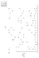
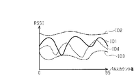
- strength of the position detection signal transmitted from each transmitter when the rotational speed of each wheel is the same.
- It is a graph which shows the relationship between the pulse count value of each rotation sensor unit when a position detection signal transmitted from the transmitter of ID1 is received a plurality of times and the received intensity, and (a) is a graph relating to the first rotation sensor unit.
- (B) is a graph regarding a 2nd rotation sensor unit,
- (c) is a graph regarding a 3rd rotation sensor unit,
- (d) is a graph regarding a 4th rotation sensor unit.
- (A) is a time chart which shows the acceleration detected by an acceleration sensor
- (b) is a time chart which shows the signal transmitted by a transmitter
- (c) is a time chart which shows the specific aspect of the wheel position by a receiver.
- the vehicle 10 is equipped with an ABS (anti-lock / brake system) 20 and a tire condition monitoring device 30.
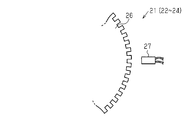
- the ABS 20 includes an ABS controller 25 and rotation sensor units 21 to 24 corresponding to the four wheels 11 of the vehicle 10, respectively.
- the first rotation sensor unit 21 corresponds to the left front wheel FL provided on the front left side of the vehicle 10
- the second rotation sensor unit 22 corresponds to the right front wheel FR provided on the front right side of the vehicle 10.
- the third rotation sensor unit 23 corresponds to the left rear wheel RL provided on the rear left side of the vehicle 10
- the fourth rotation sensor unit 24 corresponds to the right rear wheel RR provided on the rear right side of the vehicle 10. It corresponds.
- Each wheel 11 includes a vehicle wheel 12 and a tire 13 attached to the vehicle wheel 12.
- the ABS controller 25 comprises a microcomputer, ie, a circuit such as a processor, and is programmed to obtain the rotational position (rotational angle) of each wheel 11 based on signals from the rotational sensor units 21 to 24.
- the vehicle 10 is equipped with a control device 14 that comprehensively controls the operation of the vehicle 10 such as starting and stopping the engine.
- the control device 14 is connected to an ignition switch 15 that enables the driver of the vehicle 10 to start and stop the engine.
- each of the rotation sensor units 21 to 24 includes a gear 26 that rotates integrally with the wheel 11 and a detector 27 that is disposed so as to face the outer peripheral surface of the gear 26.
- the rotation sensor units 21 to 24 function as a rotation position detection unit.
- a plurality of teeth (48 in this embodiment) are provided at equal angular intervals on the outer peripheral portion of the gear 26.
- the detector 27 detects a pulse generated by the rotation of the gear 26.
- the ABS controller 25 is wired to each detector 27 and obtains the rotational position of each wheel 11 based on the pulse count value (hereinafter, pulse count value) of each detector 27. Specifically, every time the gear 26 rotates, the detector 27 generates a number of pulses corresponding to the number of teeth. The ABS controller 25 counts pulses generated in the detector 27. By dividing 360 degrees by the number of pulses generated in the detector 27 while the wheel 11 makes one rotation (360 degrees), it is possible to know how many times the gear 26 has rotated per pulse count.
- the ABS controller 25 counts from 0 to 95 by counting the rising and falling edges of the pulse.
- the tire condition monitoring device 30 includes a transmitter 31 attached to each of the four wheels 11 and a receiver 50 installed on the vehicle body of the vehicle 10. Each transmitter 31 is attached to the vehicle wheel 12 to which the tire 13 is attached so as to be disposed in the internal space of the tire 13. Each transmitter 31 detects the state of the corresponding tire 13 and wirelessly transmits a signal including data indicating the detected tire state.
- each transmitter 31 includes a pressure sensor 32, a temperature sensor 33, an acceleration sensor 34, a controller 35, a transmission circuit 36, a battery 37, and a transmission antenna 39.
- the transmitter 31 is operated by the power supplied from the battery 37, and the controller 35 controls the operation of the transmitter 31 in an integrated manner.
- the pressure sensor 32 detects the pressure (tire pressure) in the corresponding tire 13.
- the temperature sensor 33 detects the temperature in the corresponding tire 13 (in-tire temperature).
- the detection shaft 34a of the acceleration sensor 34 faces one direction in the vertical direction (vertical direction) when the transmitter 31 is located at the uppermost position of the wheel 11, and the lowermost position. When in the vertical direction, it faces in a different direction from that in the vertical direction.
- the detection axis 34a faces upward in the vertical direction
- the detection axis 34a is oriented in the vertical direction. Look down.
- the acceleration sensor 34 outputs the amount of distortion of the detection unit (for example, a diaphragm) along the detection axis 34a as a voltage.
- the detection shaft 34 a detects acceleration (centrifugal acceleration) in a direction in which centrifugal force acts as the wheel 11 rotates.
- the acceleration sensor 34 When the acceleration sensor 34 has a detection axis other than the detection axis 34a, the acceleration acting on each detection axis is individually detected. In the following description, the acceleration detected by the acceleration sensor 34 indicates the acceleration detected by the detection axis 34a.
- the controller 35 includes an electric circuit such as a microcomputer including a CPU 35a, a storage unit 35b (RAM, ROM, etc.), an input / output port and a timer, that is, a processor.
- the controller 35 functions as a transmission side control unit.
- An ID which is identification information unique to each transmitter 31 is registered in the storage unit 35b. This ID is information used to identify each transmitter 31 in the receiver 50.
- the controller 35 acquires the tire air pressure detected by the pressure sensor 32, the tire temperature detected by the temperature sensor 33, and the acceleration detected by the acceleration sensor 34 at a predetermined acquisition frequency.
- the controller 35 determines whether or not the vehicle 10 is traveling from the acceleration detected by the acceleration sensor 34.
- the centrifugal force acting on the acceleration sensor 34 increases as the wheels 11 rotate, and the acceleration detected by the acceleration sensor 34 increases. Therefore, a value larger than the acceleration detected when the vehicle 10 is stopped is set as the travel determination threshold value, and it is determined whether or not the acceleration detected by the acceleration sensor 34 is larger than the travel determination threshold value. Thus, it can be determined whether or not the vehicle 10 is traveling.
- the controller 35 outputs tire pressure data, tire temperature data, and data including ID to the transmission circuit 36.
- the transmission circuit 36 generates a signal and wirelessly transmits the signal from the transmission antenna 39.
- the transmission circuit 36 functions as a transmission unit.
- the controller 35 is programmed to control the transmission circuit 36.
- two types of signals a stationary signal and a position detection signal, are output from the transmission antenna 39.
- the stationary signal is a signal that is modulated to transmit data and is transmitted at regular intervals.
- the position detection signal is a signal that is not transmitted for data and is continuously transmitted at a constant output for a predetermined transmission time.
- the steady signal is transmitted when the rotational position of the wheel 11 is a predetermined position.
- the controller 35 transmits a steady signal when the position of the transmitter 31 is the lowest position of the wheel 11.
- the fact that the transmitter 31 is located at the lowest position can be detected from the acceleration detected by the acceleration sensor 34.
- the acceleration sensor 34 outputs the distortion amount of the detection unit as a voltage including a direct current component and an alternating current component.
- the direct current component indicates centrifugal acceleration
- the alternating current component indicates gravity acceleration.
- the controller 35 transmits a steady signal when the gravitational acceleration detected by the acceleration sensor 34 is + 1G, so that the steady signal is obtained when the transmitter 31 is located at the lowermost position (constant position) of the wheel 11. Can be sent. Therefore, the fixed position is a position where the transmitter 31 is the lowest position of the wheel 11, and the steady signal is a fixed position signal transmitted at the fixed position.
- the receiver 50 includes a reception controller 51, a reception circuit 52, and a reception antenna 56.
- a display 57 is connected to the reception controller 51 of the receiver 50.
- the reception controller 51 is connected to the ABS controller 25 and the control device 14.
- the reception controller 51 is composed of an AD converter 53, a CPU 54, a storage unit 55 (ROM, RAM, etc.), and an electric circuit such as a microcomputer or processor including an input / output port.
- the storage unit 55 supervises the operation of the receiver 50.
- the program to control is stored. That is, the reception controller 51 is programmed to control the operation of the receiver 50 in an integrated manner.
- the receiving circuit 52 demodulates the signal received from each transmitter 31 through the receiving antenna 56 and outputs information about the tire to the receiving controller 51.
- the receiving circuit 52 also includes a measuring circuit that measures the received intensity (RSSI: Received Signal Strength) of the received signal.
- RSSI Received Signal Strength
- the reception controller 51 acquires the information regarding the state of the tire 13 sent from the reception circuit 52, and grasps the tire state corresponding to the transmitter 31 of the transmission source. Further, the reception controller 51 acquires the information of the reception intensity sent from the reception circuit 52 by converting it into a digital value by the AD converter 53. Further, the reception controller 51 acquires the pulse count values of the rotation sensor units 21 to 24 based on the information sent from the ABS controller 25. The reception controller 51 causes the display device 57 to display information related to the tire pressure.
- the reception controller 51 determines whether or not an abnormality has occurred in the tire 13 from the information regarding the state of the tire 13. For example, the reception controller 51 determines whether or not the air pressure of the tire 13 is greater than the low pressure threshold. If the air pressure of the tire 13 is equal to or lower than the low pressure threshold, it is determined that an abnormality (insufficient air pressure) has occurred in the tire 13. To do. As the low pressure threshold, for example, 80% of the recommended air pressure of the tire 13 is set. And when the abnormality has arisen in the tire 13, the reception controller 51 displays on the display device 57 that the abnormality has occurred in the tire 13 to the driver, or performs a notification by a notification device. Inform.
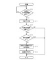
- step S ⁇ b> 10 the controller 35 determines whether or not the acceleration detected by the acceleration sensor 34 is greater than a travel determination threshold value.
- the controller 35 repeats the process of step S10.
- the controller 35 performs the process of step S11.
- the controller 35 transmits a steady signal.
- the steady signal includes ID data, tire 13 air pressure data, a status indicating the state of the vehicle 10, and a code for error correction such as CRC (cyclic redundancy check).
- step S12 the controller 35 determines whether or not the acceleration detected by the acceleration sensor 34 is larger than the transmission threshold value.
- the transmission threshold is set to a value slightly lower than the acceleration at which the amount of distortion of the detection unit of the acceleration sensor 34 reaches the limit. If the determination result of step S12 is negative, the controller 35 ends the process.
- step S12 when the determination result of step S12 is affirmative, the controller 35 performs the process of step S13.
- step S ⁇ b> 13 the controller 35 determines whether the temperature in the tire 13 detected by the temperature sensor 33 is equal to or lower than a low temperature threshold value.
- a low temperature threshold a temperature at which the voltage of the battery 37 is lowered to the extent that a problem occurs in transmitting a steady signal is set. If the voltage of the battery 37 drops so as to cause a problem in transmitting a signal, it becomes difficult to transmit the signal. For this reason, when the determination result of step S13 is affirmative, the controller 35 ends the process in order to transmit the steady signal with priority over the position detection signal.
- step S13 determines whether the determination result of step S13 is negative. If the determination result of step S13 is negative, the controller 35 performs the process of step S14. In step S ⁇ b> 14, the controller 35 determines the transmission time of the position detection signal from the acceleration detected by the acceleration sensor 34.
- the transmission time of the position detection signal is set to a time longer than the time required for the wheel 11 to make one rotation.
- the time required for one rotation of the wheel 11 varies depending on the speed of the vehicle 10. The higher the speed of the vehicle 10, the shorter the time required for the wheel 11 to make one rotation. As the speed of the vehicle 10 increases, the acceleration detected by the acceleration sensor 34 increases accordingly. Therefore, the controller 35 shortens the transmission time of the position detection signal as the acceleration detected by the acceleration sensor 34 increases. .
- a high-speed threshold value that is larger than the transmission threshold value is set, and when the acceleration detected by the acceleration sensor 34 is greater than the high-speed threshold value, the position detection signal is transmitted compared to when the acceleration is equal to or less than the high-speed threshold value. Time is shortened.
- step S15 the controller 35 transmits a position detection signal.
- the position detection signal is transmitted at a constant output for the transmission time determined in step S14.
- the position detection signal includes at least data indicating ID.
- the position detection signal is transmitted within a period until the next stationary signal is transmitted after the stationary signal is transmitted in step S14. Further, the position detection signal is transmitted a predetermined number of times after the vehicle 10 starts traveling, and after the predetermined number of transmissions are performed, the acceleration detected by the acceleration sensor 34 is a transmission threshold value. The position detection signal is not transmitted even when it becomes larger than the above. As the predetermined number of times, the number of times that the position of the wheel 11 provided with each transmitter 31 that has transmitted the position detection signal can be specified is set.
- the controller 35 detects the position detection signal. Reset the transmission count. Therefore, after that, when the acceleration detected by the acceleration sensor 34 becomes larger than the running determination threshold, the position detection signal is transmitted again a predetermined number of times.
- the controller 35 cancels the transmission stop of the position detection signal when the vehicle stops for a certain time.
- a time expected to be required to change the position of the wheel 11 such as tire rotation is set. Then, after the position of the wheel 11 is changed, the position of the wheel 11 can be specified.
- step S21 the reception controller 51 determines whether or not the reception circuit 52 has received a position detection signal.
- the determination result of step S21 is negative, that is, when the signal received by the reception circuit 52 is only a steady signal, the reception controller 51 performs the process of step S22.
- the reception controller 51 performs a first specifying process.
- the first specifying process is a process of specifying the position of the wheel 11 provided with the transmitter 31 from the pulse count value of each of the rotation sensor units 21 to 24 when the receiving circuit 52 receives the steady signal. . A specific description will be given below.
- the transmitter 31 of ID1 is mounted on the left front wheel FL
- the transmitter 31 of ID2 is mounted on the right front wheel FR
- the transmitter 31 of ID3 is mounted on the left rear wheel RL
- ID4 is transmitted.
- the machine 31 is mounted on the right rear wheel RR.
- this transmitter 31 is stationary at the time t1, t2, t3, t4, that is, the time when the transmitter 31 moves to the lowest position of the wheel 11. A signal is being output. Since the times t1, t2, t3, and t4 are times when the transmitter 31 of ID1 moves to the lowest position of the wheel 11, the rotational positions of the wheels 11 provided with the transmitter 31 of ID1 are the same at each time. Become.
- the reception controller 51 detects the pulse count value detected by each of the rotation sensor units 21 to 24 when the signal transmitted from the transmitter 31 is received a plurality of times, and the rotation sensor unit 21 having the smallest variation in the pulse count value.
- the wheels 11 corresponding to ⁇ 24 can be identified as the wheels provided with the transmitter 31 of ID1. For example, when the steady count signal from the ID1 transmitter 31 is received a plurality of times and the variation in the pulse count of the first rotation sensor unit 21 is the smallest, the ID1 transmitter 31 is provided on the left front wheel FL. Can be identified.
- transmitters 31 of IDs 2, 3, and 4 are provided due to variations in the pulse counts of the rotation sensor units 21 to 24 when a steady signal is received from the transmitters 31 of IDs 2, 3, and 4 a plurality of times.
- the position of the wheel 11 can be specified.
- step S21 when the determination result of step S21 is affirmative, that is, when the reception circuit 52 receives the position detection signal, the reception controller 51 performs the process of step S23.
- the receiving circuit 52 receives the position detection signal, the acceleration detected by the acceleration sensor 34 is larger than the transmission threshold. Accordingly, in the receiver 50, the first specific process and the second specific process are switched with the transmission threshold as a boundary.
- step S23 the reception controller 51 performs a second specific process.
- the second specifying process is a process of specifying the position of the wheel 11 provided with the corresponding transmitter 31 from the reception intensity of the position detection signal. A specific description will be given below.
- the reception intensity of the position detection signal acquired by the reception controller 51 varies depending on the rotational position of the wheel 11, that is, the pulse count value of each of the rotation sensor units 21 to 24 detected by the ABS controller 25. .
- the transmitter 31 provided on the wheel 11 transmits a position detection signal while rotating together with the wheel 11.
- the position detection signal transmitted from the transmitter 31 is attenuated by an obstacle in the vehicle 10 such as an occupant or a load in the vehicle 10 until it is received by the receiver 50.
- the amount of attenuation of the position detection signal due to the obstacle differs depending on the positional relationship between the transmitter 31 (transmitting antenna 39) and the receiver 50 (receiving antenna 56). This is because when the positional relationship between the transmitter 31 and the receiver 50 changes, the distance from the transmitter 31 to the receiver 50, the directivity of the transmission antenna 39, the positional relationship between the transmitter 31 and the obstacle, and the like change. Because.
- the position detection signal is transmitted while the positional relationship between the transmitter 31 and the receiver 50 varies, so the rotational position of the wheel 11 Among the (rotational angles), there are a range in which the position detection signal is not easily attenuated by the obstacle and a range in which the position detection signal is easily attenuated by the obstacle.
- the signal transmitted in the range in which the position detection signal is less likely to be attenuated has a stronger reception intensity, and the signal transmitted in the range in which the position detection signal is easily attenuated.
- the reception intensity becomes weaker as the part gets closer.
- the reception intensity of the position detection signal transmitted from each transmitter 31 is acquired when all the wheels 11 make one rotation at the same rotation speed, the reception is performed for each transmitter 31 that has transmitted the position detection signal.
- the reception level (absolute value) of the intensity is different from the pulse count value (the rotational position of the wheel 11) when the reception intensity is an extreme value. This is because the amount of attenuation due to an obstacle or the like varies depending on the position of the transmitter 31.
- the range in which the position detection signal is not easily attenuated and the range in which the position detection signal is easily attenuated vary depending on the presence or absence of an obstacle and the position, but a period of one run (for example, from turning on the ignition switch 15 to turning it off) If it is in the middle, the position of the obstacle in the vehicle 10 is considered to be the same. In addition, even if there is an obstacle movement such as movement of an occupant or a load, it is expected that the obstacle will not move frequently while the vehicle 10 is traveling. Therefore, the rotation position (rotation angle) of each wheel 11 when the reception intensity becomes an extreme value can be regarded as being at the same position every time unless an error or the like is taken into consideration.
- the rotational speed (rotational speed) of each wheel 11 when the vehicle 10 is running is different. For this reason, when the rotational position of the wheel 11 when the reception intensity of the position detection signal transmitted from the transmitter 31 with the same ID becomes an extreme value is detected a plurality of times, the transmitter 31 that transmits the position detection signal is provided. Only in the wheel 11, the rotation position of the wheel 11 when the reception intensity becomes an extreme value is in the same position every time. Actually, due to the tolerance of each member of the wheel position specifying device and the measurement error, the rotational position of each wheel 11 when the reception intensity becomes an extreme value varies slightly every time it is detected.
- the reception controller 51 classifies the position detection signals transmitted from each of the four transmitters 31 a plurality of times for each ID, and the wheel having the least variation in the rotational position of the wheel 11 when the reception intensity becomes an extreme value. 11 can be identified as having a transmitter 31 with a corresponding ID. Therefore, the reception controller 51 functions as a reception side control unit. When there are a plurality of extreme values in the received intensity of the position detection signal transmitted from each transmitter 31, the position of the corresponding wheel 11 may be determined from one of the plurality of extreme values, The position of the corresponding wheel 11 may be specified from the extreme value.
- an ID1 transmitter 31 is mounted on the left front wheel FL
- an ID2 transmitter 31 is mounted on the right front wheel FR
- an ID3 transmitter 31 is mounted on the left rear wheel RL. It is assumed that the transmitter 31 with ID 4 is attached to the right rear wheel RR. And the reception controller 51 assumes the case where the position of the corresponding wheel 11 is specified from the minimum value among the extreme values of the reception intensity.
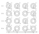
- FIGS. 10 (a) to 10 (d) pays attention to a position detection signal transmitted from the ID1 transmitter 31 (hereinafter referred to as “ID1 position detection signal”).
- ID1 position detection signal a position detection signal transmitted from the ID1 transmitter 31
- the reception intensity of the ID1 position detection signal at the rotation position (pulse count value) when rotating is shown four times.
- the reception controller 51 refers to the rotation position of each wheel 11 when the reception intensity of the position detection signal of ID1 becomes the minimum value, that is, the pulse count value detected by each of the rotation sensor units 21 to 24. Then, the reception controller 51 identifies the rotation sensor unit with the smallest variation in the pulse count value when the reception intensity of the position detection signal of ID1 becomes the minimum value. For example, the reception controller 51 acquires the reception intensity of the position detection signal of ID1 from each of the rotation sensor units 21 to 24 a plurality of times, and calculates the number of times that the minimum value of the reception intensity is included in a predetermined range. Count every 24.
- the predetermined range is a range that is set in consideration of the tolerance of each member, measurement error, and the like, and is a range in which the extreme values of the received intensity can be regarded as being at the same position.
- the reception controller 51 counts the pulses when the rotation sensor units 21 to 24 having the largest (large) number of times (ratio) the minimum value of the received intensity is included in the predetermined range are the minimum received intensity. It is determined that the wheel 11 corresponds to the wheel 11 having the smallest value variation.
- the reception controller 51 grasps that the pulse count value detected by the first rotation sensor unit 21 has the least variation. Since the first rotation sensor unit 21 is provided corresponding to the left front wheel FL, the transmitter 31 of ID1 can be specified as being provided on the left front wheel FL. Similarly, the position of the wheel 11 can be specified for the transmitter 31 of ID2, the transmitter 31 of ID3, and the transmitter 31 of ID4.
- the extreme value of the reception intensity may not be at a fixed position even though the obstacle in the vehicle 10 does not move. This is because the position of the extreme value of the reception intensity may vary depending on the surrounding environment.
- the position of the extreme value of the reception intensity varies.
- the vehicle 10 is often temporarily stopped due to a signal waiting or the like, and if the vehicle 10 is stopped, the position detection signal is not transmitted.
- a transmitter 31 that transmits a steady signal and a position detection signal, and a receiver 50 that receives a signal transmitted from the transmitter 31 and identifies the position of the wheel 11 provided with the transmitter 31 are provided. It functions as a wheel position specifying device.
- the reception controller 51 performs the first specific process while receiving only the steady signal, that is, when the acceleration detected by the acceleration sensor 34 is equal to or less than the transmission threshold. Do. In addition to the stationary signal, the reception controller 51 performs the second specifying process when receiving the position detection signal.
- the transmitter 31 stops transmitting the position detection signal when transmitting a predetermined number of position detection signals from the start of travel (after the ignition switch 15 is turned on). Therefore, according to the above embodiment, the following effects can be obtained.
- the receiving controller 51 can perform the first specifying process and the second specifying process.
- the second specifying process for specifying the position of the wheel 11 provided with the transmitter 31 from the received intensity, the position of the wheel 11 provided with the transmitter 31 is specified regardless of the position where the position detection signal is transmitted. Can do.
- the position of the wheel 11 provided with the transmitter 31 can be specified by the second specifying process.
- the vehicle 10 travels on a road with a large undulation, it is not possible to detect that the acceleration of gravity is + 1G, and even if the first specific process cannot be performed, the transmitter is performed by the second specific process.
- the position of the wheel 11 provided with 31 can be specified.
- the position detection signal is transmitted when the acceleration detected by the acceleration sensor 34 is larger than the transmission threshold.
- the position detection signal is continuously transmitted until the wheel 11 rotates by a predetermined angle (in the embodiment, 360 degrees or more). There is a need. Since the rotation speed of the wheel 11 is increased according to the speed of the vehicle 10, the time for transmitting the position detection signal can be shortened by transmitting the position detection signal when the speed of the vehicle 10 is high.
- the first specifying process is performed to reduce the number of times the position detection signal is transmitted compared to the case where the position detection signal is always transmitted. Can do. Therefore, the power consumption of the battery 37 due to the transmission of the position detection signal can be reduced.
- the position detection signal transmission time is shortened as the acceleration detected by the acceleration sensor 34 increases. For this reason, regardless of the magnitude of the acceleration detected by the acceleration sensor 34, the power consumption of the battery 37 can be reduced compared to the case where the position detection signal is always transmitted for the same transmission time.
- the received intensity of the position detection signal fluctuates with the rotation of the wheel 11, thereby generating an extreme value. It is considered that the extreme value of the reception intensity does not change within the period of one run, or does not change frequently even if it changes. For this reason, the reception controller 51 can specify the position of the wheel 11 provided with the transmitter 31 from the variation in the rotational position of the wheel 11 when the reception intensity becomes an extreme value. Therefore, even when the magnitude relationship between the absolute values of the received intensity changes due to the surrounding environment or the like, the position of the wheel 11 can be specified if the extreme value of the received intensity does not change.
- the position detection signal is transmitted from the transmitter 31 a predetermined number of times after the ignition switch 15 is turned on. For this reason, even after the position of the wheel 11 on which the transmitter 31 is provided is specified, the number of times the position detection signal is transmitted is smaller than when the position detection signal is continuously transmitted. Therefore, the power consumption of the battery 37 accompanying the transmission of the position detection signal can be reduced.
- the position detection signal is not transmitted even if the acceleration detected by the acceleration sensor 34 exceeds the transmission threshold.
- the temperature of the battery 37 is excessively low, the voltage is significantly reduced. It is desirable that the tire condition monitoring device 30 can identify which ID of the transmitter 31 is provided on which wheel 11. However, if it is possible to notify that an abnormality has occurred in any of the wheels 11, even if the position of the wheel 11 provided with the transmitter 31 is not specified, the driver is notified of the abnormality. Can do.
- the controller 35 starts transmission of the position detection signal when the acceleration detected by the acceleration sensor 34 is larger than the transmission threshold, but is not limited thereto.
- the position detection signal may be transmitted when a time (number of times) during which a signal cannot be transmitted at a certain position continues for a predetermined time.
- the speed of the vehicle 10 increases and the amount of distortion in the detection unit of the acceleration sensor 34 reaches the limit, it becomes difficult to detect gravitational acceleration and it becomes difficult to detect + 1G.
- the controller 35 when the vehicle 10 is traveling on a rough road with rough undulations (irregular roads), noise included in the acceleration detected by the acceleration sensor 34 increases, and it becomes difficult to detect + 1G.
- the controller 35 cannot detect + 1G (when the fixed position cannot be detected)
- the controller 35 includes the data of the fixed position non-detection flag in the steady signal and transmits it to the receiver 50.
- the receiver 50 receives the steady signal including the data of the fixed position non-detection flag, the receiver 50 recognizes that the position detection signal is transmitted from the transmitter 31, and performs the second specifying process.
- the position of the wheel 11 provided with the transmitter 31 is specified from the variation in the rotational position of the wheel 11 when the reception intensity becomes an extreme value, but the present invention is not limited to this, and the wheel is determined based on the magnitude relationship of the reception intensity. Eleven positions may be specified.
- the receivers 50 (reception antennas 56) are arranged so that the distances from the transmitters 31 are different, and the reception intensity of the position detection signal transmitted from each transmitter 31 is measured. Since the position detection signal transmitted from each transmitter 31 attenuates as the distance from the receiver 50 increases, the transmitter 31 that has transmitted the position detection signal having the highest reception intensity is applied to the wheel 11 closest to the receiver 50. It can be specified that it is provided. In this way, it can be specified that the wheels 11 are provided on the wheels 11 in descending order of the received intensity of the received position detection signal in the order closer to the receiver 50.
- the position where the constant position signal is transmitted may be a position different from the lowest position of the wheel 11. For example, when the constant position signal is transmitted when the acceleration sensor 34 detects ⁇ 1G, the constant position signal is transmitted at the uppermost position of the wheel 11.
- the first specific process and the second specific process may be performed in parallel.
- the steady signal is transmitted at a fixed position, and the transmission time of the steady signal is increased to such an extent that the position of the wheel 11 can be specified by the second specifying process.
- the reception controller 51 performs the first specifying process from the pulse count values of the rotation sensor units 21 to 24 at the time when the steady signal is received, and performs the second specifying process from the reception intensity of the steady signal.
- the steady signal functions as a constant position signal and a position detection signal. That is, the fixed position signal and the position detection signal may not be separate signals but may be the same signal.
- the position detection signal may not include data indicating the ID.
- the controller 35 may transmit a recognition signal that causes the receiver 50 to recognize that the position detection signal is transmitted to the receiver 50 immediately before transmitting the position detection signal.
- the recognition signal includes data indicating an ID.
- the receiver 50 Upon receiving the position detection signal, the receiver 50 detects the position from the transmitter 31 having the same ID as the recognition signal received immediately before receiving the position detection signal. Know that a signal has been sent.
- the position of the wheel 11 may be specified from the variation in the pulse count value when the reception intensity is the maximum value among the plurality of extreme values. Similarly, the position of the wheel 11 may be specified from the variation of the pulse count value when the reception intensity is an extreme value different from the minimum value and the maximum value among the plurality of extreme values.
- the position of the wheel 11 where the transmitter 31 is provided may be specified from the variation in the rotational position of the wheel 11 when the reception intensity reaches each extreme value. For example, assuming that one of a plurality of extreme values is a first extreme value and the other extreme value is a second extreme value, the variation in the rotational position of the wheel 11 when the reception intensity becomes the first extreme value.
- the position of the wheel 11 provided with the transmitter 31 may be determined from the variation in the rotational position of the wheel 11 when the reception intensity becomes the second extreme value when the position of the wheel 11 cannot be determined from .
- the position of the wheel 11 where the transmitter 31 is provided is determined from the variation in the rotational position of the wheel 11 when the reception intensity becomes the first extreme value and when the reception intensity becomes the second extreme value. You may specify.
- the reception controller 51 determines the wheel 11 with the least variation in the rotational position of the wheel 11 when the reception intensity is each of the first extreme value and the second extreme value, and determines that the variation is the smallest. It may be specified that the transmitter 31 is provided on the wheel 11 having a high (high) number of times (ratio).
- the position detection signal may be transmitted from the transmitter 31 continuously for a time shorter than the time required for the wheel 11 to make one rotation.
- the time for transmitting the position detection signal is the time required for the wheel 11 to rotate 300 degrees (5/6 rotation) or the time required for the wheel 11 to rotate 270 degrees (3/4 rotation). May be. That is, the transmission time of the position detection signal may be a time when at least one extreme value can be detected.
- the rotational position of the wheel 11 to which the position detection signal is transmitted is set to a constant position for each transmission. It is preferable.
- the rotation position of the wheel 11 when the transmitter 31 (acceleration sensor 34) is positioned at the lowest position of the wheel 11 is set to a fixed position, and the transmitter circuit 36 is moved when the transmitter 31 moves to the lowest position of the wheel 11.
- the position detection signal may be transmitted from.
- the fact that the transmitter 31 has moved to the lowest position of the wheel 11 is detected by detecting that the acceleration of gravity is 1 G ( ⁇ 1 G) by the acceleration sensor 34 or detecting the rotational position of the wheel 11. can do.
- ⁇ High-speed threshold may be set in multiple stages. For example, a first high speed threshold value and a second high speed threshold value that is larger than the first high speed threshold value may be set. In this case, when the acceleration detected by the acceleration sensor 34 is greater than the first high speed threshold, the transmission time of the position detection signal is shorter than when the acceleration detected by the acceleration sensor 34 is equal to or lower than the first high speed threshold. . When the acceleration detected by the acceleration sensor 34 becomes larger than the second high speed threshold, the transmission time of the position detection signal is further shortened.
- the position detection signal is not transmitted when the temperature in the tire 13 detected by the temperature sensor 33 is equal to or lower than the low temperature threshold. Instead, the position detection signal transmission frequency is changed. May be reduced.
- a position detection signal may be transmitted regardless of the temperature in the tire 13 detected by the temperature sensor 33.
- the temperature sensor 33 may not be provided.
- the position detection signal when the temperature in the tire 13 detected by the temperature sensor 33 is equal to or lower than the low temperature threshold, the position detection signal is not transmitted, but instead, the voltage of the battery 37 is detected, The position detection signal may not be transmitted when the voltage of the battery 37 becomes equal to or lower than the voltage threshold.
- the voltage threshold for example, a value slightly higher than a value at which a steady signal cannot be transmitted is set. Further, it may be determined whether or not to transmit the position detection signal from both the temperature in the tire 13 detected by the temperature sensor 33 and the voltage of the battery 37.
- a capacitor connected in parallel to the transmission circuit 36 may be provided.
- electric charge is stored in the capacitor by power supply from the battery 37.
- a steady signal can be transmitted with the electric charge stored in the capacitor.
- the voltage of the battery 37 decreases, and the voltage of the battery 37 may decrease so that a steady signal cannot be transmitted. Even in this case, it is possible to store the charge in the capacitor when the steady signal is not transmitted and transmit the steady signal by this charge.
- -Vehicle 10 should just be a vehicle which has a plurality of wheels 11, and vehicles other than four wheels may be sufficient as it. -Both the rise and fall of the pulse are counted, but only the rise or fall of the pulse may be counted. In this case, the pulse count value is half that when both rising and falling are counted.
- the number of gear teeth may be changed. That is, the number of pulses generated in the rotation sensor units 21 to 24 when the wheel 11 rotates once may be changed.
- the transmission threshold value may be the same value as the travel determination threshold value. That is, the transmission of the steady signal may be started simultaneously with the transmission of the position detection signal.
- -Display 57 does not need to be provided in vehicle 10, and may use a portable terminal etc. which a driver has instead as a display.
- the steady signal may include data indicating the temperature in the tire 13.
- the number of times of obtaining the rotational position of the wheel 11 when the reception intensity of the position detection signal becomes an extreme value may be any number as long as the position of the wheel 11 can be specified.
- the transmission of the position detection signal may be stopped by transmitting a signal that instructs the transmitter 31 to cancel the transmission stop from the trigger device.
Abstract
Description
これによれば、加速度センサによって検出される加速度が大きくなったときには、位置検出信号の送信時間も短くすることができる。このため、位置検出信号の送信に伴う電力消費を低減させることができる。 About the said wheel position specific apparatus, the transmission time of the said position detection signal may differ according to the acceleration detected by the said acceleration sensor.
According to this, when the acceleration detected by the acceleration sensor increases, the transmission time of the position detection signal can be shortened. For this reason, the power consumption accompanying transmission of a position detection signal can be reduced.
図1(a)に示すように、車両10は、ABS(アンチロック・ブレーキシステム)20及びタイヤ状態監視装置30を搭載している。ABS20は、ABSコントローラ25と、車両10の4つの車輪11にそれぞれ対応する回転センサユニット21~24とを備えている。 Hereinafter, an embodiment of the wheel position specifying device will be described.
As shown in FIG. 1A, the
図1(a)に示すように、タイヤ状態監視装置30は、4つの車輪11にそれぞれ取り付けられた送信機31と、車両10の車体に設置される受信機50とを備えている。各送信機31は、タイヤ13の内部空間に配置されるように、そのタイヤ13が装着された車両用ホイール12に対して取り付けられている。各送信機31は、対応するタイヤ13の状態を検出して、検出されたタイヤ状態を示すデータを含む信号を無線送信する。 As shown in FIG. 3, in this embodiment, the
As shown in FIG. 1A, the tire
図5に示すように、ステップS10において、コントローラ35は、加速度センサ34によって検出される加速度が走行判定用閾値よりも大きいか否かを判断する。ステップS10の判定結果が否定の場合、コントローラ35は、ステップS10の処理を繰り返す。一方で、ステップS10の判定結果が肯定の場合、コントローラ35は、ステップS11の処理を行う。コントローラ35は、ステップS11において、定常信号を送信させる。定常信号には、IDのデータ、タイヤ13の空気圧データ、車両10の状態を示すステータス、及びCRC(cyclic redundancy check)などの誤り訂正のための符号が含まれている。 First, the control performed by the
As shown in FIG. 5, in step S <b> 10, the
図6に示すように、ステップS21において、受信コントローラ51は、受信回路52が位置検出信号を受信したか否かを判定する。ステップS21の判定結果が否定の場合、すなわち、受信回路52が受信した信号が定常信号のみである場合には、受信コントローラ51は、ステップS22の処理を行う。 Next, control performed by the
As shown in FIG. 6, in step S21, the
図11(a)に示すように、車両10が加速し、車輪11の回転数(回転速度)が上昇していくと、これに従い加速度センサ34によって検出される加速度も大きくなる。 Next, the operation of the wheel position specifying device will be described.
As shown in FIG. 11A, when the
したがって、上記実施形態によれば、以下のような効果を得ることができる。 The
Therefore, according to the above embodiment, the following effects can be obtained.
・実施形態において、コントローラ35は、加速度センサ34によって検出される加速度が送信閾値よりも大きくなったことを契機として位置検出信号の送信を開始させたが、これに限られない。例えば、一定位置で信号を送信できない時間(回数)が所定時間継続したときに位置検出信号を送信するようにしてもよい。車両10の速度が速くなり、加速度センサ34の検出部の歪み量が限界に達すると、重力加速度を検出することが困難となり、+1Gを検出しにくくなる。 In addition, you may change embodiment as follows.
In the embodiment, the
例えば、複数の極値のうちの一つを第1の極値、他の極値を第2の極値とすると、受信強度が第1の極値となるときの車輪11の回転位置のばらつきから車輪11の位置特定を行えなかったときに、受信強度が第2の極値となるときの車輪11の回転位置のばらつきから送信機31が設けられた車輪11の位置特定を行ってもよい。 When there are a plurality of extreme values in the reception intensity, the position of the
For example, assuming that one of a plurality of extreme values is a first extreme value and the other extreme value is a second extreme value, the variation in the rotational position of the
例えば、位置検出信号が送信される時間は、車輪11が300度回転(5/6回転)するのに要する時間や、車輪11が270度回転(3/4回転)するのに要する時間であってもよい。すなわち、位置検出信号の送信時間とは、少なくとも一つの極値が検出できる時間であればよい。 The position detection signal may be transmitted from the
For example, the time for transmitting the position detection signal is the time required for the
・実施形態では、温度センサ33によって検出されるタイヤ13内の温度が低温閾値以下となったときには、位置検出信号を送信していないが、これに代えて、バッテリ37の電圧を検出して、バッテリ37の電圧が電圧閾値以下となったときに位置検出信号の送信をしないようにしてもよい。電圧閾値としては、例えば、定常信号を送信することができなくなる値よりも若干高めの値に設定される。また、温度センサ33によって検出されるタイヤ13内の温度、及び、バッテリ37の電圧の両方から位置検出信号を送信するか否かを判定してもよい。 A position detection signal may be transmitted regardless of the temperature in the
In the embodiment, when the temperature in the
・パルスの立ち上がりと立ち下がりの両方をカウントしたが、パルスの立ち上がり又はパルスの立ち下がりのみをカウントしてもよい。この場合、パルスカウント値は、立ち上がりと立ち下がりの両方をカウントするときの半分となる。 -
-Both the rise and fall of the pulse are counted, but only the rise or fall of the pulse may be counted. In this case, the pulse count value is half that when both rising and falling are counted.
・送信閾値は、走行判定用閾値と同一の値であってもよい。すなわち、定常信号の送信が位置検出信号の送信と同時に開始されてもよい。 ・ The number of gear teeth may be changed. That is, the number of pulses generated in the
The transmission threshold value may be the same value as the travel determination threshold value. That is, the transmission of the steady signal may be started simultaneously with the transmission of the position detection signal.
・定常信号には、タイヤ13内の温度を示すデータが含まれていてもよい。 -
-The steady signal may include data indicating the temperature in the
・位置検出信号の送信停止は、トリガ装置から送信機31に送信停止の解除を指示する信号を送信することで行ってもよい。 The number of times of obtaining the rotational position of the
The transmission of the position detection signal may be stopped by transmitting a signal that instructs the
Claims (4)
- 複数の車輪それぞれの回転位置を検出する回転位置検出部を有する車両に搭載されるように構成される車輪位置特定装置であって、
前記複数の車輪それぞれに設けられた送信機と、
前記車両の車体に設けられた受信機と、を備え、
前記各送信機は、
前記受信機に向けて信号を送信するように構成される送信部と、
対応する前記車輪とともに回転して、自身に作用する加速度を検出する加速度センサと、
前記加速度センサによって検出される加速度に基づいて一定位置で送信される一定位置信号、及び、一定出力で送信される位置検出信号を前記送信部から送信させるように構成される送信側制御部と、を有し、
前記受信機は、
前記信号を受信するように構成される受信部と、
前記一定位置信号を受信した時点での各車輪の回転位置のばらつきから対応する前記送信部が設けられた車輪の位置を特定する第1の特定処理と、前記位置検出信号の受信強度から対応する前記送信機が設けられた車輪の位置を特定する第2の特定処理と、を行うように構成される受信側制御部と、を有する車輪位置特定装置。 A wheel position specifying device configured to be mounted on a vehicle having a rotation position detection unit that detects a rotation position of each of a plurality of wheels,
A transmitter provided on each of the plurality of wheels;
A receiver provided on a vehicle body of the vehicle,
Each transmitter is
A transmitter configured to transmit a signal toward the receiver;
An acceleration sensor that rotates with the corresponding wheel and detects acceleration acting on the wheel;
A transmission-side control unit configured to cause the transmission unit to transmit a fixed position signal transmitted at a fixed position based on acceleration detected by the acceleration sensor, and a position detection signal transmitted at a constant output; Have
The receiver
A receiver configured to receive the signal;
Corresponding from the first specifying process for specifying the position of the wheel provided with the corresponding transmission unit from the variation in the rotational position of each wheel at the time of receiving the constant position signal, and the received intensity of the position detection signal A wheel position specifying device, comprising: a receiving side control unit configured to perform a second specifying process for specifying a position of a wheel provided with the transmitter. - 前記各送信側制御部は、前記加速度センサによって検出される加速度が送信閾値以下のときに前記一定位置信号を送信させ、前記加速度センサによって検出される加速度が前記送信閾値より大きいときに前記位置検出信号を送信させるように構成され、
前記受信側制御部は、前記受信部が前記一定位置信号を受信し、前記位置検出信号を受信しないときには前記第1の特定処理を行い、前記受信部が前記位置検出信号を受信したときには前記第2の特定処理を行うように構成される請求項1に記載の車輪位置特定装置。 Each of the transmission side control units transmits the constant position signal when the acceleration detected by the acceleration sensor is equal to or less than a transmission threshold, and the position detection when the acceleration detected by the acceleration sensor is larger than the transmission threshold. Configured to send a signal,
The receiving side control unit performs the first specifying process when the receiving unit receives the fixed position signal and does not receive the position detection signal, and performs the first specifying process when the receiving unit receives the position detection signal. The wheel position specifying device according to claim 1, configured to perform two specifying processes. - 前記加速度センサによって検出される加速度に応じて前記位置検出信号の送信時間が異なる請求項2に記載の車輪位置特定装置。 The wheel position specifying device according to claim 2, wherein a transmission time of the position detection signal differs according to an acceleration detected by the acceleration sensor.
- 前記各送信側制御部は、前記一定位置で前記一定位置信号を送信できない時間が所定時間継続したときに前記位置検出信号を送信させるように構成される請求項1に記載の車輪位置特定装置。 The wheel position specifying device according to claim 1, wherein each of the transmission side control units is configured to transmit the position detection signal when a time during which the constant position signal cannot be transmitted at the fixed position continues for a predetermined time.
Priority Applications (6)
| Application Number | Priority Date | Filing Date | Title |
|---|---|---|---|
| US15/025,304 US9913005B2 (en) | 2015-06-26 | 2015-06-26 | Wheel assembly position identifying apparatus |
| KR1020167007144A KR101768830B1 (en) | 2015-06-26 | 2015-06-26 | Wheel assembly position identifying apparatus |
| PCT/JP2015/068476 WO2016208055A1 (en) | 2015-06-26 | 2015-06-26 | Wheel-position specifying device |
| JP2015549884A JP6027265B1 (en) | 2015-06-26 | 2015-06-26 | Wheel positioning device |
| CN201580001987.1A CN108025604B (en) | 2015-06-26 | 2015-06-26 | Wheel position determining device |
| EP15831122.5A EP3132952B1 (en) | 2015-06-26 | 2015-06-26 | Wheel-position specifying device |
Applications Claiming Priority (1)
| Application Number | Priority Date | Filing Date | Title |
|---|---|---|---|
| PCT/JP2015/068476 WO2016208055A1 (en) | 2015-06-26 | 2015-06-26 | Wheel-position specifying device |
Publications (1)
| Publication Number | Publication Date |
|---|---|
| WO2016208055A1 true WO2016208055A1 (en) | 2016-12-29 |
Family
ID=57326564
Family Applications (1)
| Application Number | Title | Priority Date | Filing Date |
|---|---|---|---|
| PCT/JP2015/068476 WO2016208055A1 (en) | 2015-06-26 | 2015-06-26 | Wheel-position specifying device |
Country Status (6)
| Country | Link |
|---|---|
| US (1) | US9913005B2 (en) |
| EP (1) | EP3132952B1 (en) |
| JP (1) | JP6027265B1 (en) |
| KR (1) | KR101768830B1 (en) |
| CN (1) | CN108025604B (en) |
| WO (1) | WO2016208055A1 (en) |
Cited By (2)
| Publication number | Priority date | Publication date | Assignee | Title |
|---|---|---|---|---|
| JPWO2020070782A1 (en) * | 2018-10-01 | 2021-05-06 | 太平洋工業株式会社 | Tire condition monitoring system, transmitter and receiver |
| JP2022115843A (en) * | 2021-01-28 | 2022-08-09 | 系統電子工業股▲ふん▼有限公司 | Automatically positioning method of tire-pressure detector with antennas |
Families Citing this family (1)
| Publication number | Priority date | Publication date | Assignee | Title |
|---|---|---|---|---|
| EP3699054B1 (en) * | 2018-11-30 | 2022-03-02 | Pacific Industrial Co., Ltd. | Road surface information collection device |
Citations (6)
| Publication number | Priority date | Publication date | Assignee | Title |
|---|---|---|---|---|
| JP2006312342A (en) * | 2005-05-06 | 2006-11-16 | Denso Corp | Wheel position detector and tire pressure detector having the same |
| JP2010030449A (en) * | 2008-07-29 | 2010-02-12 | Nippon Soken Inc | Trigger unit mounting structure for tire air pressure detector |
| JP2010122023A (en) | 2008-11-19 | 2010-06-03 | Nissan Motor Co Ltd | Device and method for monitoring tire pressure |
| JP2012240468A (en) * | 2011-05-17 | 2012-12-10 | Nissan Motor Co Ltd | Tire air pressure monitoring device |
| JP2014083884A (en) * | 2012-10-19 | 2014-05-12 | Tokai Rika Co Ltd | Wheel position discrimination unit and tire air pressure monitoring system |
| JP2014231337A (en) * | 2013-05-30 | 2014-12-11 | 太平洋工業株式会社 | Wheel position specification device |
Family Cites Families (8)
| Publication number | Priority date | Publication date | Assignee | Title |
|---|---|---|---|---|
| DE102007028518A1 (en) * | 2007-06-21 | 2008-12-24 | Robert Bosch Gmbh | Method for determining the wheel position in a vehicle |
| JP4544296B2 (en) * | 2007-12-10 | 2010-09-15 | 株式会社日本自動車部品総合研究所 | Trigger machine mounting structure in wheel position detector |
| US8332104B2 (en) * | 2009-09-22 | 2012-12-11 | Schrader Electronics Ltd. | System and method for performing auto-location of a tire pressure monitoring sensor arranged with a vehicle wheel |
| US8498785B2 (en) * | 2010-09-07 | 2013-07-30 | Trw Automotive U.S. Llc | Method and apparatus for determining tire position on a vehicle |
| MY165692A (en) | 2011-05-17 | 2018-04-20 | Nissan Motor | Tire pressure monitoring device |
| KR101340850B1 (en) | 2011-12-15 | 2013-12-12 | 현대자동차주식회사 | Method for Auto Recogniting of Tire Pressure Monitoring System |
| US8498759B1 (en) * | 2012-02-20 | 2013-07-30 | Trw Automotive U.S. Llc | Method and apparatus for determining a condition and relative location of an inner tire and an outer tire of a tire pair |
| KR20150048406A (en) | 2013-10-28 | 2015-05-07 | 현대자동차주식회사 | Fast auto-location decision for TPMS |
-
2015
- 2015-06-26 US US15/025,304 patent/US9913005B2/en active Active
- 2015-06-26 EP EP15831122.5A patent/EP3132952B1/en active Active
- 2015-06-26 CN CN201580001987.1A patent/CN108025604B/en active Active
- 2015-06-26 WO PCT/JP2015/068476 patent/WO2016208055A1/en active Application Filing
- 2015-06-26 KR KR1020167007144A patent/KR101768830B1/en active IP Right Grant
- 2015-06-26 JP JP2015549884A patent/JP6027265B1/en active Active
Patent Citations (6)
| Publication number | Priority date | Publication date | Assignee | Title |
|---|---|---|---|---|
| JP2006312342A (en) * | 2005-05-06 | 2006-11-16 | Denso Corp | Wheel position detector and tire pressure detector having the same |
| JP2010030449A (en) * | 2008-07-29 | 2010-02-12 | Nippon Soken Inc | Trigger unit mounting structure for tire air pressure detector |
| JP2010122023A (en) | 2008-11-19 | 2010-06-03 | Nissan Motor Co Ltd | Device and method for monitoring tire pressure |
| JP2012240468A (en) * | 2011-05-17 | 2012-12-10 | Nissan Motor Co Ltd | Tire air pressure monitoring device |
| JP2014083884A (en) * | 2012-10-19 | 2014-05-12 | Tokai Rika Co Ltd | Wheel position discrimination unit and tire air pressure monitoring system |
| JP2014231337A (en) * | 2013-05-30 | 2014-12-11 | 太平洋工業株式会社 | Wheel position specification device |
Non-Patent Citations (1)
| Title |
|---|
| See also references of EP3132952A4 |
Cited By (4)
| Publication number | Priority date | Publication date | Assignee | Title |
|---|---|---|---|---|
| JPWO2020070782A1 (en) * | 2018-10-01 | 2021-05-06 | 太平洋工業株式会社 | Tire condition monitoring system, transmitter and receiver |
| JP7002561B2 (en) | 2018-10-01 | 2022-01-20 | 太平洋工業株式会社 | Tire condition monitoring system, transmitter and receiver |
| JP2022115843A (en) * | 2021-01-28 | 2022-08-09 | 系統電子工業股▲ふん▼有限公司 | Automatically positioning method of tire-pressure detector with antennas |
| JP7309938B2 (en) | 2021-01-28 | 2023-07-18 | 系統電子工業股▲ふん▼有限公司 | Automatic positioning method for tire pressure detector with multiple antennas |
Also Published As
| Publication number | Publication date |
|---|---|
| CN108025604A (en) | 2018-05-11 |
| KR101768830B1 (en) | 2017-08-17 |
| EP3132952B1 (en) | 2019-01-02 |
| US20170155977A1 (en) | 2017-06-01 |
| EP3132952A4 (en) | 2017-08-02 |
| JPWO2016208055A1 (en) | 2017-06-29 |
| US9913005B2 (en) | 2018-03-06 |
| CN108025604B (en) | 2020-02-21 |
| JP6027265B1 (en) | 2016-11-16 |
| EP3132952A1 (en) | 2017-02-22 |
Similar Documents
| Publication | Publication Date | Title |
|---|---|---|
| JP6027261B1 (en) | Wheel positioning device | |
| JP6027266B1 (en) | Tire condition detection device and tire condition monitoring device | |
| JP6329265B2 (en) | Wheel positioning device | |
| US10525779B2 (en) | Receiver | |
| JP6027265B1 (en) | Wheel positioning device | |
| JP5956021B1 (en) | Wheel positioning device | |
| JP6430915B2 (en) | Acceleration correction device, acceleration correction program, and tire condition detection device | |
| JP6407808B2 (en) | Wheel positioning device | |
| JP2016203722A (en) | Wheel position determination device | |
| JP2015197369A (en) | travel detection device | |
| JP2013226861A (en) | Wheel position determining device |
Legal Events
| Date | Code | Title | Description |
|---|---|---|---|
| ENP | Entry into the national phase |
Ref document number: 2015549884 Country of ref document: JP Kind code of ref document: A |
|
| REEP | Request for entry into the european phase |
Ref document number: 2015831122 Country of ref document: EP |
|
| WWE | Wipo information: entry into national phase |
Ref document number: 2015831122 Country of ref document: EP |
|
| WWE | Wipo information: entry into national phase |
Ref document number: 15025304 Country of ref document: US |
|
| 121 | Ep: the epo has been informed by wipo that ep was designated in this application |
Ref document number: 15831122 Country of ref document: EP Kind code of ref document: A1 |
|
| NENP | Non-entry into the national phase |
Ref country code: DE |