WO2016208001A1 - Image processing device, endoscope device, program, and image processing method - Google Patents
Image processing device, endoscope device, program, and image processing method Download PDFInfo
- Publication number
- WO2016208001A1 WO2016208001A1 PCT/JP2015/068186 JP2015068186W WO2016208001A1 WO 2016208001 A1 WO2016208001 A1 WO 2016208001A1 JP 2015068186 W JP2015068186 W JP 2015068186W WO 2016208001 A1 WO2016208001 A1 WO 2016208001A1
- Authority
- WO
- WIPO (PCT)
- Prior art keywords
- region
- bubble
- arc curve
- bubble region
- input image
- Prior art date
Links
- 238000012545 processing Methods 0.000 title claims abstract description 154
- 238000003672 processing method Methods 0.000 title claims description 5
- 239000000284 extract Substances 0.000 claims abstract description 23
- 238000000034 method Methods 0.000 claims description 102
- 230000008569 process Effects 0.000 claims description 56
- 238000009826 distribution Methods 0.000 claims description 29
- 230000008859 change Effects 0.000 claims description 20
- 238000001727 in vivo Methods 0.000 claims description 11
- 238000001514 detection method Methods 0.000 description 55
- 238000000605 extraction Methods 0.000 description 26
- 238000003384 imaging method Methods 0.000 description 20
- 230000006870 function Effects 0.000 description 11
- 238000004364 calculation method Methods 0.000 description 10
- 238000012986 modification Methods 0.000 description 8
- 230000004048 modification Effects 0.000 description 8
- 239000013598 vector Substances 0.000 description 8
- 239000000203 mixture Substances 0.000 description 6
- 238000003860 storage Methods 0.000 description 5
- 238000005520 cutting process Methods 0.000 description 4
- 238000010586 diagram Methods 0.000 description 4
- 238000006243 chemical reaction Methods 0.000 description 3
- 230000000694 effects Effects 0.000 description 3
- 230000003902 lesion Effects 0.000 description 3
- 238000007781 pre-processing Methods 0.000 description 3
- 230000015572 biosynthetic process Effects 0.000 description 2
- 239000003086 colorant Substances 0.000 description 2
- 238000007796 conventional method Methods 0.000 description 2
- 238000005315 distribution function Methods 0.000 description 2
- 238000011835 investigation Methods 0.000 description 2
- 230000003287 optical effect Effects 0.000 description 2
- 238000000926 separation method Methods 0.000 description 2
- 238000003786 synthesis reaction Methods 0.000 description 2
- 230000008901 benefit Effects 0.000 description 1
- 230000000295 complement effect Effects 0.000 description 1
- 239000002131 composite material Substances 0.000 description 1
- 230000001276 controlling effect Effects 0.000 description 1
- 230000007423 decrease Effects 0.000 description 1
- 230000005484 gravity Effects 0.000 description 1
- 238000003709 image segmentation Methods 0.000 description 1
- 238000003780 insertion Methods 0.000 description 1
- 230000037431 insertion Effects 0.000 description 1
- 238000005304 joining Methods 0.000 description 1
- 238000002357 laparoscopic surgery Methods 0.000 description 1
- 239000007788 liquid Substances 0.000 description 1
- 239000004973 liquid crystal related substance Substances 0.000 description 1
- 239000008177 pharmaceutical agent Substances 0.000 description 1
- 230000001105 regulatory effect Effects 0.000 description 1
- 239000004065 semiconductor Substances 0.000 description 1
- 239000007921 spray Substances 0.000 description 1
- 238000005507 spraying Methods 0.000 description 1
- 239000000126 substance Substances 0.000 description 1
Images


Classifications
-
- A—HUMAN NECESSITIES
- A61—MEDICAL OR VETERINARY SCIENCE; HYGIENE
- A61B—DIAGNOSIS; SURGERY; IDENTIFICATION
- A61B1/00—Instruments for performing medical examinations of the interior of cavities or tubes of the body by visual or photographical inspection, e.g. endoscopes; Illuminating arrangements therefor
- A61B1/00002—Operational features of endoscopes
- A61B1/00004—Operational features of endoscopes characterised by electronic signal processing
- A61B1/00009—Operational features of endoscopes characterised by electronic signal processing of image signals during a use of endoscope
-
- A—HUMAN NECESSITIES
- A61—MEDICAL OR VETERINARY SCIENCE; HYGIENE
- A61B—DIAGNOSIS; SURGERY; IDENTIFICATION
- A61B1/00—Instruments for performing medical examinations of the interior of cavities or tubes of the body by visual or photographical inspection, e.g. endoscopes; Illuminating arrangements therefor
- A61B1/04—Instruments for performing medical examinations of the interior of cavities or tubes of the body by visual or photographical inspection, e.g. endoscopes; Illuminating arrangements therefor combined with photographic or television appliances
- A61B1/041—Capsule endoscopes for imaging
-
- A—HUMAN NECESSITIES
- A61—MEDICAL OR VETERINARY SCIENCE; HYGIENE
- A61B—DIAGNOSIS; SURGERY; IDENTIFICATION
- A61B1/00—Instruments for performing medical examinations of the interior of cavities or tubes of the body by visual or photographical inspection, e.g. endoscopes; Illuminating arrangements therefor
- A61B1/04—Instruments for performing medical examinations of the interior of cavities or tubes of the body by visual or photographical inspection, e.g. endoscopes; Illuminating arrangements therefor combined with photographic or television appliances
- A61B1/042—Instruments for performing medical examinations of the interior of cavities or tubes of the body by visual or photographical inspection, e.g. endoscopes; Illuminating arrangements therefor combined with photographic or television appliances characterised by a proximal camera, e.g. a CCD camera
-
- G—PHYSICS
- G06—COMPUTING; CALCULATING OR COUNTING
- G06F—ELECTRIC DIGITAL DATA PROCESSING
- G06F18/00—Pattern recognition
- G06F18/20—Analysing
- G06F18/23—Clustering techniques
- G06F18/232—Non-hierarchical techniques
- G06F18/2323—Non-hierarchical techniques based on graph theory, e.g. minimum spanning trees [MST] or graph cuts
-
- G—PHYSICS
- G06—COMPUTING; CALCULATING OR COUNTING
- G06T—IMAGE DATA PROCESSING OR GENERATION, IN GENERAL
- G06T7/00—Image analysis
- G06T7/0002—Inspection of images, e.g. flaw detection
- G06T7/0012—Biomedical image inspection
-
- G—PHYSICS
- G06—COMPUTING; CALCULATING OR COUNTING
- G06T—IMAGE DATA PROCESSING OR GENERATION, IN GENERAL
- G06T7/00—Image analysis
- G06T7/10—Segmentation; Edge detection
- G06T7/11—Region-based segmentation
-
- G—PHYSICS
- G06—COMPUTING; CALCULATING OR COUNTING
- G06T—IMAGE DATA PROCESSING OR GENERATION, IN GENERAL
- G06T7/00—Image analysis
- G06T7/10—Segmentation; Edge detection
- G06T7/12—Edge-based segmentation
-
- G—PHYSICS
- G06—COMPUTING; CALCULATING OR COUNTING
- G06T—IMAGE DATA PROCESSING OR GENERATION, IN GENERAL
- G06T7/00—Image analysis
- G06T7/10—Segmentation; Edge detection
- G06T7/136—Segmentation; Edge detection involving thresholding
-
- G—PHYSICS
- G06—COMPUTING; CALCULATING OR COUNTING
- G06T—IMAGE DATA PROCESSING OR GENERATION, IN GENERAL
- G06T7/00—Image analysis
- G06T7/60—Analysis of geometric attributes
-
- G—PHYSICS
- G06—COMPUTING; CALCULATING OR COUNTING
- G06T—IMAGE DATA PROCESSING OR GENERATION, IN GENERAL
- G06T7/00—Image analysis
- G06T7/60—Analysis of geometric attributes
- G06T7/64—Analysis of geometric attributes of convexity or concavity
-
- G—PHYSICS
- G06—COMPUTING; CALCULATING OR COUNTING
- G06V—IMAGE OR VIDEO RECOGNITION OR UNDERSTANDING
- G06V10/00—Arrangements for image or video recognition or understanding
- G06V10/40—Extraction of image or video features
- G06V10/44—Local feature extraction by analysis of parts of the pattern, e.g. by detecting edges, contours, loops, corners, strokes or intersections; Connectivity analysis, e.g. of connected components
-
- G—PHYSICS
- G06—COMPUTING; CALCULATING OR COUNTING
- G06V—IMAGE OR VIDEO RECOGNITION OR UNDERSTANDING
- G06V10/00—Arrangements for image or video recognition or understanding
- G06V10/70—Arrangements for image or video recognition or understanding using pattern recognition or machine learning
- G06V10/762—Arrangements for image or video recognition or understanding using pattern recognition or machine learning using clustering, e.g. of similar faces in social networks
- G06V10/7635—Arrangements for image or video recognition or understanding using pattern recognition or machine learning using clustering, e.g. of similar faces in social networks based on graphs, e.g. graph cuts or spectral clustering
-
- G—PHYSICS
- G06—COMPUTING; CALCULATING OR COUNTING
- G06T—IMAGE DATA PROCESSING OR GENERATION, IN GENERAL
- G06T2207/00—Indexing scheme for image analysis or image enhancement
- G06T2207/10—Image acquisition modality
- G06T2207/10024—Color image
-
- G—PHYSICS
- G06—COMPUTING; CALCULATING OR COUNTING
- G06T—IMAGE DATA PROCESSING OR GENERATION, IN GENERAL
- G06T2207/00—Indexing scheme for image analysis or image enhancement
- G06T2207/10—Image acquisition modality
- G06T2207/10068—Endoscopic image
-
- G—PHYSICS
- G06—COMPUTING; CALCULATING OR COUNTING
- G06T—IMAGE DATA PROCESSING OR GENERATION, IN GENERAL
- G06T2207/00—Indexing scheme for image analysis or image enhancement
- G06T2207/30—Subject of image; Context of image processing
- G06T2207/30004—Biomedical image processing
-
- G—PHYSICS
- G06—COMPUTING; CALCULATING OR COUNTING
- G06V—IMAGE OR VIDEO RECOGNITION OR UNDERSTANDING
- G06V2201/00—Indexing scheme relating to image or video recognition or understanding
- G06V2201/03—Recognition of patterns in medical or anatomical images
- G06V2201/031—Recognition of patterns in medical or anatomical images of internal organs
Definitions
- the present invention relates to an image processing device, an endoscope device, a program, an image processing method, and the like.
- Patent Document 1 discloses a method of detecting a candidate point constituting a bubble shape from an image, and extracting a bubble shape by detecting a circular shape based on the candidate point.
- Non-Patent Document 1 discloses a method for detecting an arc curve that does not require complicated parameter setting.
- Patent Document 1 in order to detect a circular shape, there is a problem that a structure other than a bubble having a circular shape is erroneously extracted as a bubble region. Further, since Non-Patent Document 1 detects an arc curve, it does not consider whether the arc curve is a bubble or a structure other than a bubble. As for other conventional methods, there is no disclosure of a method for performing processing based on the brightness (luminance) of the image inside and outside the circular arc curve forming the bubble.
- an image processing device an endoscope device, a program, an image processing method, and the like that accurately extract a bubble region from an input image.
- One aspect of the present invention includes an image acquisition unit that acquires an input image, and a processing unit that performs a process of extracting a bubble region from the input image.
- the processing unit detects an arc curve from the input image. The change in the luminance of the pixel in the direction from the inner side to the outer side of the circular arc curve is determined, and the circular arc curve that is determined to change in the direction in which the luminance increases in the direction from the inner side to the outer side.
- This is related to an image processing device that detects a region constituted by the representative bubble region and extracts the bubble region from the input image based on the representative bubble region.
- a representative bubble region is detected based on a change in luminance between the inside and outside of the arc curve, and the bubble region is extracted based on the representative bubble region.
- the processing unit determines a degree of coincidence between a gradient direction of the pixel value on the arc curve and an eccentric direction of the arc curve, and the degree of coincidence is determined to be high. In this case, it may be determined that the luminance changes in a direction in which the luminance increases in the direction from the inner side toward the outer side.
- the processing unit may detect the circular arc curve by combining a plurality of pixels determined to have similar gradient directions.
- the processing unit may determine the degree of coincidence between the gradient direction in the target pixel included in the circular arc curve and the eccentric direction in the target pixel, thereby determining the arc. In the direction from the inner side to the outer side of the curve, it may be determined whether or not the luminance changes in a direction of increasing brightness.
- the processing unit may extract a region including the representative bubble region as the bubble region.
- the processing unit obtains a bubble region feature amount based on a feature amount of a pixel included in the representative bubble region, and the feature amount of the pixels of the input image is the bubble.
- a set of pixels determined to be similar to the region feature amount may be extracted as the bubble region.
- the processing unit extracts a region including the representative bubble region as the bubble region by dividing the input image into regions by graph cut processing based on the bubble region feature amount. May be.
- the processing unit may calculate the feature amount of the pixel of the input image and the cost as a cost for a link connecting the node representing the representative bubble region and the node representing the pixel of the input image.
- a value based on the similarity with the bubble region feature amount may be set, and the graph cut process may be executed based on the cost.
- the processing unit may include a set of pixels in which the similarity of the feature amount to the bubble region feature amount is equal to or greater than a given threshold among the pixels of the input image. It may be extracted as a region.
- the processing unit calculates the feature amount based on a pixel value and coordinates, and the bubble region feature amount is a distribution of the feature amount of pixels included in the representative bubble region. May be a function approximating.
- the processing unit may detect a region constituted by the arc curve having a center angle of the arc curve equal to or greater than a given threshold as the representative bubble region.
- the processing unit may detect an area formed by the arc curve in which a radius of the arc curve is within a given range as the representative bubble area.
- the input image is an in-vivo image
- the processing unit performs a process of detecting a region of interest from an area excluding the extracted bubble area in the in-vivo image. You may go.
- the other aspect of this invention contains the image acquisition part which acquires an input image, and the process part which performs the process which extracts a bubble area
- the said process part is a circular arc curve from the said input image. And detecting a region constituted by at least a part of the circular arc curve as a representative bubble region, and obtaining a bubble region feature amount based on a feature amount of a pixel included in the representative bubble region Further, the present invention relates to an image processing apparatus that extracts the bubble region from the input image by dividing the input image into regions by graph cut processing based on the bubble region feature amount.
- the representative bubble region is detected from the arc curve, and the bubble region is extracted by a graph cut process using the bubble region feature amount obtained from the representative bubble region.
- the bubble region feature amount obtained from the representative bubble region is extracted by a graph cut process using the bubble region feature amount obtained from the representative bubble region.
- Another aspect of the present invention relates to an endoscope apparatus including the image processing apparatus described above.
- a computer functions as an image acquisition unit that acquires an input image and a processing unit that performs a process of extracting a bubble region from the input image.
- An arc curve is detected, and it is determined whether the luminance of the pixel inside the arc curve is darker than the luminance of the pixel outside the arc curve, and in the direction from the inner side toward the outer side,
- a program that detects a region constituted by the circular arc curve determined to change in a direction in which brightness is increased as a representative bubble region, and extracts the bubble region from the input image based on the representative bubble region. Involved.
- an arc curve is detected from an input image, and it is determined whether or not the luminance of the pixel inside the arc curve is darker than the luminance of the pixel outside the arc curve. Then, in the direction from the inner side to the outer side, an area constituted by the circular arc curve determined to change in the direction in which the brightness is increased is detected as a representative bubble area, and based on the representative bubble area.
- the present invention relates to an image processing method for extracting a bubble region from the input image.
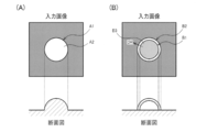
- FIG. 1A shows an example of an arc curve caused by a structure other than bubbles
- FIG. 1B shows an example of an arc curve caused by bubbles.
- 1 is a configuration example of an image processing apparatus according to the present embodiment.
- 1 is a detailed configuration example of an image processing apparatus according to the present embodiment.
- 6A is an example of an input image
- FIG. 6B is an example of an arc curve detection process result
- FIG. 6C is an example of a representative bubble area detection process result
- FIG. 6D is a bubble area extraction process.
- Example results The structural example of the endoscope apparatus which concerns on this embodiment.
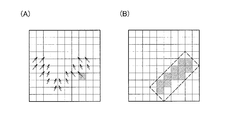
- FIG. 11A and FIG. 11B are diagrams for explaining detection processing of a similar gradient direction region.
- a bubble area may be extracted and the bubble area may be used as an unnecessary area.
- the presence of a bubble hinders observation of an object behind it (an object in the same direction as the bubble when viewed from the imaging unit and a distance from the imaging unit farther than the bubble) on the input image.
- the bubble area is extracted, the area to be observed on the input image can be limited to areas other than the bubble area, so that the burden on the observer (image viewer) can be reduced.
- Patent Document 1 discloses a method for extracting a bubble region by detecting a circular shape.
- the extraction method of the bubble area in Patent Document 1 is based on a circular detection process, if there is a circular structure on the image, it becomes a detection target even if the structure is not a bubble. End up.
- FIG. 1A a case in which a subject having a planar shape as a whole and having a convex portion protruding from another portion in a part thereof is imaged from the front. Think.
- Patent Document 1 also discloses a method of detecting a specular reflection region with high luminance and determining that there is a circular shape corresponding to a bubble in the vicinity thereof.
- a structure that is convex toward the imaging unit shown in FIG. 1A light easily enters the convex part, and reflected light from the convex part easily reaches the imaging part. Therefore, there is a high possibility that a bright image is captured. That is, even in a structure other than a bubble, a high-luminance (bright) region may appear in the vicinity of the arc curve, specifically, in the inside A2 of the arc curve. The possibility of false detection cannot be denied.
- the present applicant proposes a bubble region extraction method that suppresses the possibility of erroneously detecting the structure shown in FIG.
- the present applicant has the characteristic that the arc curve resulting from the bubble structure is dark (low brightness) and bright outside (high brightness) inside the arc curve, and such brightness characteristics are other than bubbles.
- the arc curve may not be a closed figure (a circle that is part of a perfect circle or ellipse). Think inside and outside.
- FIG. Since the boundary portion of the bubble is brightly imaged due to the influence of the reflected light from the film, if this film portion has a certain thickness, the arc curve B1 corresponding to the inside of the film and the outside of the film on the input image An arc curve B2 corresponding to is imaged.
- the specular reflection does not occur in the inner portion of the circular arc curve B1
- the reflected light from the film is difficult to reach the imaging unit in the region, or the light is refracted in the film.
- the image is darkened (B3).
- the luminance is extremely high in the portion where specular reflection occurs as described above (C1).
- the bubbles become spherical due to surface tension, it is difficult to assume that the entire surface of the arc curve has specular reflection, and at least a part of the inner area of the arc curve is represented by B3 in FIG. Similarly, a dark region is expected (C2 in FIG. 2).
- the luminance of the pixel is changed in the opposite direction, that is, in the direction from the inside of the arc curve to the outside. Changes from bright to dark. In this way, the bubbles that are the detection target and the structures other than the bubbles that are not the detection target have different brightness change trends inside and outside the arc curve. It becomes possible to do.
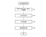
- the image processing apparatus includes an image acquisition unit 200 that acquires an input image, and a processing unit 100 that performs a process of extracting a bubble region from the input image. . Then, the processing unit 100 detects an arc curve from the input image, determines a change in luminance of the pixel in the direction from the inner side to the outer side of the arc curve, and changes in a direction in which the luminance increases in the direction from the inner side to the outer side. A region constituted by the arc curve determined to be performed is detected as a representative bubble region, and the bubble region is extracted from the input image based on the representative bubble region.
- the representative bubble region is extracted in the method of the present embodiment.
- the captured image is FIG. 6A to be described later
- the representative bubble region is, for example, FIG. 6C.
- C1 of FIG. 2 even within the arc curve representing the bubble, the brightness is very high in the region where the specular reflection occurs. Therefore, as shown in C4 of FIG. 2, there is a possibility that an arc curve cannot be detected in the first place because there is no luminance difference from the boundary portion of the bubble, and even if an arc curve is detected at the boundary portion, In the circular arc curve, the luminance changes in the direction from the inner side to the outer side of the circular arc curve in which the luminance becomes darker.
- the representative bubble region in this embodiment is a representative region of the bubble region, a region that is likely to be a bubble region in the input image, and detects the entire bubble region as the representative bubble region. There is no need.
- the final bubble region to be extracted is FIG. 6 (D). Therefore, the processing for obtaining FIG. 6 (D) from FIG. 6 (C) (bubble region extraction processing in a narrow sense) is performed. Will be executed. Details of the bubble region extraction processing will be described later.
- the bubble is imaged as a shape having a double arc curve (B1, B2).
- the object to be detected is the inner arc curve ( B1, C3 in the example of FIG. 2, and the outer circular curve (B2) is out of detection.
- the inner side is a high luminance region corresponding to the film, and the outer side is a subject other than bubbles, so that the luminance is relatively low. This is because it changes in the direction of darkening. However, this is not a problem because it is sufficient to detect the inner circular arc curve in detecting bubbles.
- the input image according to the present embodiment may be an in-vivo image in particular.
- the processing unit 100 performs processing for detecting a region of interest from a region excluding the extracted bubble region in the in-vivo image.
- the calculation area can be reduced and processing can be performed efficiently by excluding the bubble region from the region of interest detection processing.
- the attention area here is an area where the above-mentioned subject to be noted is imaged, and specifically, a lesion area.
- the bubble region is erroneously detected as the attention region (lesion region).
- the processing accuracy can be improved by excluding the bubble region from the attention region detection processing.
- the in-vivo image has a great advantage by extracting the bubble region as compared with a general landscape image or the like, and has a great effect when the method of this embodiment is applied.
- the input image in this embodiment can target various images that may contain bubbles.
- the input image may be an image obtained by capturing the spray environment in the spraying of the pharmaceutical agent.
- FIG. 5 shows a system configuration example of the image processing apparatus according to the present embodiment.
- the image processing apparatus includes an image acquisition unit 200 and a processing unit 100.
- the processing unit 100 includes an arc curve detection unit 110, a representative bubble region detection unit 120, a bubble region feature value calculation unit 130, and a bubble region extraction unit. 140 is included.
- the image processing apparatus is not limited to the configuration shown in FIG. 5, and various modifications such as omission of some of these components and addition of other components are possible.
- the image acquisition unit 200 acquires an input image.
- the input image here is, for example, FIG. 6A, and bubbles may be captured in the input image.
- the arc curve detection unit 110 detects an arc curve from the input image.
- the method of Non-Patent Document 1 may be used, and in this case, the arc curve detected by the arc curve detection unit 110 has a somewhat similar gradient direction on the arc curve.
- FIG. 6B shows an example of the arc curve detection result for the input image of FIG. Note that FIG. 6B is an example in which the method of Non-Patent Document 1 is directly applied, and thus not only the arc curve but also the line segment is detected.
- the representative bubble region detection unit 120 detects a region that is highly likely to be a bubble region based on the detected arc curve as a representative bubble region.
- the one that is highly likely to be an arc curve caused by bubbles is selected from the arc curves detected in FIG. 6B.
- the arc curve may be selected on the condition that the luminance of the pixel changes in the direction from the inner side to the outer side of the arc curve. More specifically, the degree of coincidence between the gradient direction of the pixel value and the eccentric direction may be determined on the circular arc curve, and details will be described later.
- the representative bubble area detected here is, for example, an area expressed in white in FIG.
- the bubble region feature amount calculation unit 130 obtains a bubble region feature amount, which is a feature amount representing the bubble region, based on pixel information included in the representative bubble region.
- the bubble region extraction unit 140 extracts a bubble region from the input image based on the bubble region feature amount. If the entire process performed by the image processing apparatus according to the present embodiment is defined as a broad bubble region extraction process, the process in the bubble region extraction unit 140 is a narrow bubble region extraction process.
- the narrow bubble region extraction processing is processing for obtaining the bubble region by expanding the representative bubble region, and corresponds to the processing for obtaining FIG. 6 (D) through FIG. 6 (D).
- a graph cut method may be used, and details will be described later.
- the method of the present embodiment is not limited to that applied to the image processing apparatus, and may be applied to, for example, an endoscope apparatus.
- An endoscope apparatus (endoscope system) according to the present embodiment will be described with reference to FIG.
- the endoscope apparatus according to the present embodiment includes a rigid endoscope 10 that is an insertion part into the body, an imaging unit 20 connected to the rigid endoscope 10, a processing device 30, a display unit 40, and an external I / F unit 50. And a light source unit 60.
- the light source unit 60 includes a white light source 61 that generates white light, and a light guide cable 62 that guides light emitted from the white light source 61 to a rigid mirror.
- the rigid mirror 10 includes a lens system 11 including an objective lens, a relay lens, an eyepiece, and the like, and a light guide portion 12 that guides light emitted from the light guide cable 62 to the distal end of the rigid mirror.
- the imaging unit 20 includes an imaging lens system 24 that forms an image of light emitted from the lens system 11.
- the imaging lens system 24 includes a focus lens 22 that adjusts the in-focus object position.
- the imaging unit 20 further includes an imaging element 25 that photoelectrically converts the reflected light imaged by the imaging lens system 24 to generate an image, a focus lens driving unit 23 that drives the focus lens 22, and autofocus (hereinafter referred to as AF). ) Is provided with an AF start / end button 21 for controlling the start and end of.
- the image sensor 25 is, for example, a primary color Bayer type image sensor in which any of RGB color filters is arranged in a Bayer array.
- an image sensor using a complementary color filter a multilayer image sensor that can receive light of different wavelengths with one pixel without using a color filter, a monochrome image sensor without using a color filter, etc. Any image sensor can be used as long as an image can be obtained by imaging a subject.
- the focus lens driving unit 23 is an arbitrary actuator such as a voice coil motor (VCM).
- the processing device 30 corresponds to the image processing device described above, and includes the image acquisition unit 31 (corresponding to the image acquisition unit 200) and the processing unit 32 (corresponding to the processing unit 100) as described above with reference to FIG. ing.
- the image acquisition unit 31 acquires a captured image captured by the imaging unit 20 as an input image.
- the captured image acquired here is a temporally continuous (time-series) image in a narrow sense.
- the image acquisition unit 31 may be, for example, an A / D conversion unit, and the A / D conversion unit performs a process of converting analog signals sequentially output from the image sensor 25 into a digital image.
- the image acquisition unit 31 (or a preprocessing unit (not shown)) may perform preprocessing on the captured image.
- the preprocessing is image processing such as white balance and interpolation processing (demosaicing processing).
- the processing unit 32 has the same configuration as in FIG. 5 and performs a broad bubble region extraction process. Further, as described above, the processing unit 32 may perform a process of detecting a region of interest from a region excluding the extracted bubble region in the in-vivo image. Further, the processing unit 32 may perform other processing such as AF control.
- the processing device 30 (control device, control unit) is connected to the external I / F unit 50, the image sensor 25, the AF start / end button 21, and the light source unit 60, and inputs and outputs control signals.
- the external I / F unit 50 is an interface for performing input from the user to the endoscope apparatus. For example, a setting button for setting the position and size of the AF area, and a parameter for adjusting image processing parameters. It includes an adjustment button.
- the display unit 40 is a liquid crystal monitor, for example, and displays images sequentially output from the processing unit 32.
- FIG. 7 a rigid endoscope used in laparoscopic surgery or the like has been described as an example.
- the configuration of the endoscope apparatus is not limited to this, and other endoscopes such as an upper endoscope and a lower endoscope are used. It may be a device.
- the endoscope apparatus is not limited to the configuration shown in FIG. 7, and various modifications such as omitting some of these components or adding other components are possible.
- the focus lens 22 and the like are included.
- the endoscope apparatus according to the present embodiment may be configured not to perform AF, and these components are omitted. Is possible.
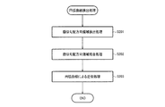
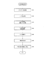
- FIG. 8 is a flowchart for explaining processing in this embodiment. Hereinafter, processing performed in each unit of the image processing apparatus will be described in detail along the flowchart.
- the input image here is, for example, an RGB three-channel image, and the following description will be made by taking an RGB three-channel image as an example.
- the arc curve detection unit 110 detects an arc curve from the input image (S101). A detailed flow of the arc curve detection process will be described with reference to the flowchart of FIG.
- a similar gradient direction region is first detected (S201).
- the gradient direction here is a direction representing the gradient and change of the pixel value, for example, information that can be defined for each pixel of the input image, and may be obtained by the method shown in FIG.
- the input image is an RGB three-channel image
- three values of RGB are used as the pixel value of each pixel.
- a luminance value may be obtained based on three pixel values of RGB, and the direction representing the gradient and change of the luminance value may be set as the gradient direction of the pixel value.
- the RGB 3 channel image may be converted into a Gray 1 channel image, and the gradient direction of the pixel value of the converted image may be defined as the gradient direction of the pixel value.
- the gradient direction may be obtained by using any pixel value of RGB, or a synthesized pixel value is obtained based on two pixel values of RGB, and the gradient direction is determined using the synthesized pixel value. You may ask for it.
- the three pixel values of RGB may be synthesized at a synthesis ratio different from the synthesis ratio for obtaining the general luminance value Y, and the gradient direction may be obtained from the result. That is, the gradient direction of the pixel value according to the present embodiment is a direction that represents the gradient or change of the pixel value information based on the pixel value of each pixel in a broad sense, and various values such as the luminance value described above as the pixel value information. Information can be used.
- a luminance value will be described.
- a vertical gradient and a horizontal gradient are obtained for a processing target pixel.
- the vertical gradient for example, a difference value between the luminance value of the pixel one pixel above the processing target pixel and the luminance value of the pixel one pixel below may be used.
- the gradient direction in the vertical direction is a direction from the smaller luminance value to the larger luminance value, and is expressed by the sign of the difference value. For example, if the value obtained by subtracting the luminance value of the lower pixel from the luminance value of the upper pixel is positive, the gradient direction is upward, and if it is negative, the gradient direction is downward. Further, the absolute value of the difference value is used for the gradient strength in the vertical direction.
- the gradient here may be a vector whose direction is the gradient direction and whose magnitude is the gradient strength.
- a vector representing the gradient in the horizontal direction is obtained based on the difference value between the luminance value of the right pixel of the processing target pixel and the luminance value of the left pixel.
- the gradient direction at the processing target pixel may be a direction of a vector that represents a gradient in the vertical direction and a vector that represents a gradient in the horizontal direction.
- the gradient direction of the pixel to be processed is the direction of a vector V3 that represents a gradient in the vertical direction and a vector V3 that represents the gradient in the horizontal direction.
- Y1 is the luminance value of the pixel one pixel above the processing target pixel
- Y2 is the luminance value of the pixel one pixel below the processing target pixel
- Y3 is the luminance value of the pixel one pixel to the right of the processing target pixel.
- the value Y4 represents the luminance value of the pixel one pixel to the left of the processing target pixel, and ⁇ is an angle representing the gradient direction when the counterclockwise direction is the positive direction with respect to the right direction.
- the gradient direction is obtained from two directions, ie, the vertical direction and the horizontal direction.
- the gradient direction may be obtained in consideration of the oblique direction by using the surrounding 8 pixels. Variations are possible.
- a similar gradient direction area is obtained by combining a plurality of pixels having similar gradient directions based on the gradient direction obtained for each pixel. For example, when an adjacent pixel has a similar gradient direction with a given pixel as a base point, a process of including the adjacent pixel in the similar gradient direction region may be performed.
- FIGS. 11 (A) and 11 (B) A schematic diagram of the gradient direction region detection processing is shown in FIGS. 11 (A) and 11 (B).
- FIG. 11A shows an example of the gradient direction in each pixel.
- the display of the gradient direction is omitted for pixels whose gradient intensity is a predetermined value or less. If the pixel indicated by the diagonal line in FIG. 11A is used as a base point, the pixel coupled to the pixel is the pixel indicated by the diagonal line in FIG. B) is a broken line area.
- FIG. 11B the pixels included in one similar gradient direction region have similar gradient directions.
- adjacent similar gradient direction regions are combined (S202).
- the direction of the similar gradient direction area is obtained, and an angle defined by the directions of the two similar gradient direction areas is a given angle range (an angle range that forms a smooth convex shape). ).
- the similar gradient direction region is rectangular as shown in FIG. 11B, the long side direction of the rectangle may be used as the direction of the similar gradient direction region.
- the representative gradient direction of the similar gradient direction region may be obtained and combined when the angle defined by the two representative gradient directions is within a given angle range.
- the average gradient direction of all pixels included in the similar gradient direction area may be used as the representative gradient direction.
- the similar gradient direction since the gradient direction of each pixel is similar in the similar gradient direction area as described above, the similar gradient direction.
- the gradient direction of a given pixel included in the region may be the representative gradient direction.
- S203 the similar gradient direction regions combined in S202 are approximated by an arc curve (S203).
- S203 an arc curve
- the processing of S201 to S203 can be realized by the method of Non-Patent Document 1, for example. With the above processing, when an arc curve is detected from the input image and attention is paid to one arc curve, the gradient direction is similar in each pixel on the arc curve.
- the arc curve detection process of S101 is not limited to the process of FIG. 9, and other modifications are possible.
- an arc curve may be detected by Hough conversion or the like. In this case, it is only necessary to detect only an arc curve whose pixel value gradient direction is constant on the arc curve, or to reject after detecting other arc curves.
- the representative bubble region detection unit 120 detects a representative bubble region that is highly likely to be a bubble region based on the arc curve detected in S101 (S102). However, in S102, it is necessary to adopt a circular curve detected in S101 that satisfies a given condition.
- the circular arc curve to be detected in the present embodiment is one in which the luminance of the pixel changes brightly in the direction from the inside to the outside. That is, when the gradient direction is defined as the direction in which the luminance value increases as described above, that is, the direction in which the luminance changes brightly, the gradient direction is the direction from the inside to the outside of the arc curve. Used for detection.
- FIG. 13 shows a flowchart for explaining the flow of the representative bubble area detection process.
- the eccentric direction here is a direction from the inner side to the outer side of the circular shape defined by the circular arc curve, specifically, a direction away from the center. Therefore, for example, the center of a circular shape defined by an arc curve may be obtained, and the direction from the center toward a given pixel on the arc curve may be set as the eccentric direction for the pixel.
- the eccentric direction may be a direction from the inner side to the outer side of the circular shape, and is not limited to the center of the circle, the focal point of the ellipse, and the center of gravity.
- the process for determining the degree of coincidence between the gradient direction and the eccentric direction may use, for example, an inner product of vectors representing two directions. Specifically, it may be determined that the degree of matching is high when the inner product is positive and the degree of matching is low when the inner product is 0 or less. In other words, when the difference between the gradient direction and the eccentric direction is smaller than 90 degrees, it is determined that the degree of coincidence is high.
- the angle formed by the two directions may be specifically obtained, and the angle may be compared with a given angle threshold value. If the angle threshold here is made small, the degree of coincidence between the two directions will be determined strictly.
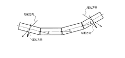
- the arc curve used for the representative bubble region detection process may be limited by other conditions. Specifically, the center angle of the arc curve is obtained, it is determined whether the center angle ⁇ is equal to or greater than a predetermined threshold ⁇ _ ⁇ , and an arc curve that is equal to or greater than the threshold is employed (S302).
- An arc curve having a small central angle has a small curvature (a large curvature radius) as shown in FIG.
- the circular arc curve D1 may not detect a part of the circular shape (D2) but may detect a part of the shape (D3) different from the circular shape.
- the case clearly corresponds to a different structure from the bubble region. That is, by excluding a circular arc curve having an excessively small central angle from processing, it is possible to suppress the possibility of erroneously detecting a structure other than a bubble such as D3 as a bubble.
- the radius r of the arc curve is included in a predetermined section (for example, ⁇ _r1 or more and ⁇ _r2 or less), and the arc curve including the radius r in the section is adopted. Good (S303). Thereby, an arc curve with an excessively small radius and an arc curve with an excessively large radius can be excluded from the processing.
- An arc curve with an excessively small radius is an arc curve detected by chance and is unlikely to be a bubble.
- an object behind can be observed, and it may be better not to detect it as a bubble. That is, by limiting the section of radius r, it is possible to detect an arc curve that is highly necessary to be handled as a bubble, and it is possible to increase the detection accuracy.
- an appropriate one is selected (adopted) from the arc curves detected in S101, and an area constituted by the selected arc curve is set as a representative bubble area.
- Various areas composed of arcuate curves are conceivable.
- a fan-shaped area having an arcuate curve as an arc may be used (S304).
- FIG. 13 shows an example in which S301 to S303 are performed in the above order, the order of these processes may be changed. Further, it is possible to perform a modification such as omitting the processes of S302 and S303.
- a modification such as omitting the processes of S302 and S303.
- the bubble area feature value calculation unit 130 calculates a feature value distribution for the pixels included in the representative bubble area and sets it as the bubble area feature value (S103).
- Various feature amounts are conceivable here.
- a five-dimensional feature amount of the coordinates (x, y) of each pixel and the pixel values (R, G, B) of each color may be used.
- the representative bubble region is assumed to be a region including a plurality of pixels, and a five-dimensional feature amount is obtained from each pixel, each element (x , Y, R, G, B) also vary within a certain range. Therefore, in this embodiment, as described above, such variation (distribution) of the feature amount is approximated using a given model.
- the distribution of feature values may be approximated using a Gaussian mixture model.
- bubbles may exist in two or more places.
- (x, y) has a distribution having a plurality of peaks.
- the color of the bubbles also changes depending on the situation (for example, in the case of an in-vivo image, a part to be imaged), there is a possibility that the distribution has a plurality of peaks. Even in such a case, the Gaussian mixture model can be approximated with high accuracy.
- the expression of the distribution of feature quantities is not limited to approximation by a Gaussian mixture model.
- the distribution of feature values may be expressed using a histogram.
- the bubble region extraction unit 140 extracts a bubble region based on the bubble region feature amount obtained from the representative bubble region (S104).
- a graph cut method may be used to extract the bubble region.
- the graph cut method is a method used for image region extraction, etc., and represents the entire image with a graph structure using the color distribution and edge information of the image as energy, solved as a maximum flow problem (Maxflow), and the energy is A binary mask image is obtained by assigning labels of 0 and 1 so as to be minimized.
- FIG. 15 is a schematic diagram for explaining the processing of the graph cut method.
- the upper node NA in FIG. 15 is, for example, a node representing a bubble area
- the lower node NB is a node representing a non-bubble area.
- the plane F1 corresponds to the input image
- the nodes N 11 to N pq on F1 represent each pixel in the input image.
- the graph is separated into an area connected to the node NA and an area connected to the node NB.
- the node (pixel) connected to the node NA after separation is determined to be a bubble region, and the node (pixel) connected to the node NB after separation is determined to be a non-bubble region.
- a cutting method minimum cutting that minimizes the cost (energy) required for cutting at that time is searched.
- the inter-pixel adjacent energy E_edge is calculated. This is the energy given to the link between a node representing a given pixel and a node representing a pixel adjacent to that pixel.
- foreground likelihood energy and background likelihood energy are calculated for all pixels of the input image as follows.
- the foreground likelihood energy E_f is energy given to the link between the node NA representing the bubble region and each of the nodes N 11 to N pq .
- Foreground likelihood energy E_f may use the similarity between the feature amount (pixel coordinates and pixel value) of the target pixel and the above-described bubble region feature amount.
- the bubble feature amount is approximated by the distribution indicated by G1 in FIG.
- FIG. 16 shows an example in which the feature quantity is one-dimensional and the approximated distribution is also a simple Gaussian distribution in order to simplify the description.
- the feature amount x ′ of the pixel is the value shown in FIG.
- the similarity (foreground likelihood energy) between the feature amount of the pixel and the bubble region feature amount is ⁇ itself or a value based on ⁇ . do it. That is, since the energy increases as the feature amount is similar to the bubble region feature amount, the link between the pixel and the NA is less likely to be disconnected, and the pixel is easily determined to be a bubble region.
- the foreground region (bubble region) and the background region are applied by applying the graph cut method to the input image based on the adjacent energy between pixels, the foreground likelihood energy, and the background likelihood energy. What is necessary is just to divide
- Various specific procedures for the bubble region extraction processing using the above-described graph cut method may be considered, but may be realized by, for example, the flowchart shown in FIG.
- an energy calculation process is first performed (S401). Specifically, the above-described processing for obtaining the adjacent pixel energy E_edge, foreground likelihood energy E_f, and background likelihood energy E_b is performed.
- node setting processing is performed (S402). Specifically, each pixel of the input image is set as a node. Furthermore, a source node (corresponding to NA) and a sink node (corresponding to NB) are added as special nodes representing the foreground area and the background area.
- a process for setting a link with the special node is performed (S403). Specifically, for each pixel, a link that connects the source node and itself is set, and the foreground likelihood energy E_f obtained in S401 is set as a weight for the link. Similarly, a link connecting the sink node and itself is set, and the background likelihood energy E_b obtained in S401 is set as a weight for the link.
- a process for setting a link between adjacent nodes is performed (S404). Specifically, a link is set between each pixel and an adjacent pixel, and the energy between adjacent pixels obtained in S401 is set as a weight for the link.
- the link is cut so that the set of nodes connected to the source node and the set of nodes connected to the sink node are completely separated (S405). At this time, the link is cut with a combination of links that minimizes the total weight set for the link to be cut.
- the combination of links as described above is calculated by the graph cut method.
- the foreground region (bubble region) and the background region (non-bubble region) are set based on the search result (S406). Specifically, a set of nodes connected to the source node and the sink node in the state where the disconnection is performed is set as a foreground area and a background area, respectively.
- the foreground area of the divided areas is extracted as the bubble area (S407).
- region feature-value is not limited to the graph cut method mentioned above.
- the similarity between the feature amount of each pixel of the input image and the bubble region feature amount may be simply obtained, and a set of pixels having the similarity greater than a predetermined threshold ⁇ _s may be extracted as the bubble region.
- the processing unit 100 determines the degree of coincidence between the gradient direction of the pixel value on the arc curve and the eccentric direction of the arc curve, and the degree of coincidence When it is determined that the brightness is high, it is determined that the luminance changes in the direction from the inner side toward the outer side of the circular arc curve.
- the gradient direction is information indicating the direction in which the luminance changes.
- the eccentric direction is a direction from the inside to the outside of the arc curve, and in a narrow sense, from the center of a circle defined by the arc curve (with the arc curve as a part thereof) to the target pixel on the arc curve.
- the direction to go is the eccentric direction at the target pixel.
- the degree of coincidence may be determined using the sign of the inner product as described above, or may be determined by a comparison process between an angle formed by two directions and a given threshold value.
- the processing unit 100 may detect an arc curve by combining a plurality of pixels determined to have similar gradient directions.
- the gradient direction is obtained for each pixel here. Therefore, whether or not the gradient directions between the pixels are similar may be determined by obtaining the gradient directions at the two target pixels, respectively, and determining that they are similar when the difference between the gradient directions is small. More specifically, an angle formed by two gradient directions may be obtained, and it may be determined that the gradient directions are similar when the difference between the angles is small (for example, a given threshold value or less).
- the processing unit 100 determines the degree of coincidence between the gradient direction of the target pixel included in the circular arc curve and the eccentric direction of the target pixel, thereby determining the circular arc curve. In the direction from the inner side to the outer side, it can be determined whether or not the luminance changes in the direction of increasing brightness.
- the target pixel here may be set to one pixel for each region of a plurality of similar gradient direction regions corresponding to one circular arc curve, for example.
- the adjacent similar gradient direction regions are in a positional relationship that forms a smooth convex shape, and the change in the representative gradient direction is somewhat small. (The latter condition is not essential). Therefore, when three or more similar gradient direction regions are combined as shown in FIG. 12, the absolute gradient direction in each similar gradient direction region may not match, but the gradient direction in each similar gradient direction region It is expected that the relationship between the smooth convex shape (that is, the arc curve) and the direction from the inner side to the outer side is similar in the entire area of the target arc curve.
- the representative gradient direction of the right similar gradient direction area is the lower right direction
- the representative gradient direction of the left similar gradient direction area is the lower left direction.
- the relationship “the degree of coincidence in the eccentric direction is high” is common in all the similar gradient direction regions.
- a relationship that “the degree of coincidence between the gradient direction and the eccentric direction is low” another similar gradient direction Also in the region, it is assumed that the degree of coincidence between the gradient direction and the eccentric direction is low.
- the “target pixel” for determining the degree of coincidence between the gradient direction and the eccentric direction does not have to be set for each similar gradient direction area. 1 pixel) may be set.
- the processing unit 100 may extract a region including the representative bubble region as a bubble region.
- the portion C4 is not detected as an arc curve in the first place, or even if detected, the luminance change does not satisfy the condition, so the representative bubble region is, for example, the region corresponding to C3 (C3 Is a sector with a circular arc). That is, in the method of the present embodiment, there is a possibility that the representative bubble area is only a part of the input image even if the entire circular bubble is captured.
- the region including the representative bubble region by extracting the region including the representative bubble region, it is possible to appropriately determine the region that has leaked in the representative bubble region detection stage as the bubble region. In addition, it is not necessary to detect the entire bubble region in the detection step of the representative bubble region, so that only the region that is likely to be a bubble (high bubble likelihood) is detected in the detection of the representative bubble region. This means that it is possible to suppress the possibility of erroneously detecting a region other than the bubble region as the representative bubble region. Specifically, based on the representative bubble area shown in FIG. 6C, the area of FIG. 6D including the area can be extracted as the bubble area.
- the processing unit 100 (in a narrow sense, the bubble region feature amount calculation unit 130 and the bubble region extraction unit 140) obtains the bubble region feature amount based on the feature amount of the pixel included in the representative bubble region, and the pixel of the input image Among them, a set of pixels whose feature amount is determined to be similar to the bubble region feature amount may be extracted as the bubble region.
- whether or not the feature quantity of a given pixel and the bubble area feature quantity are similar may be determined by obtaining the similarity between the two feature quantities. For example, if the feature amount of each pixel and the bubble region feature amount are (x, y, R, G, B) five-dimensional vectors, the similarity is, for example, SAD (SumSof Absolute Difference), SSD (Sum of Squared). Difference) or the like may be used. Since SAD and SSD are index values representing the degree of dissimilarity, the degree of similarity decreases as SAD or the like increases. However, in the present embodiment, it is assumed that the bubble region feature amount is expressed as a distribution (function) as described above with reference to FIG.
- the bubble feature region is a function f (x, y, R, G, B) for x, y, R, G, B, and the feature amount of a given pixel is (x ′, y ′, R ′).
- the similarity may be f (x ′, y ′, R ′, G ′, B ′) or a value based thereon.
- the graph cut method simply determines whether or not the feature amount of a given pixel and the bubble region feature amount are similar (whether or not the foreground likelihood energy is large).
- the bubble region is extracted in consideration of other viewpoints (by searching for the minimum cut in consideration of energy between adjacent pixels).
- the bubble region feature amount obtained from the representative bubble region is a feature amount that well represents the feature of the bubble. For this reason, the level of similarity with the bubble region feature amount indicates the level of the possibility of being a bubble, and therefore it is accurately determined whether each pixel is a bubble region by using the similarity. It becomes possible.
- the processing unit 100 extracts the region including the representative bubble region as the bubble region by dividing the input image by the graph cut processing based on the bubble region feature amount. May be.
- the graph cut method is a method widely used also in image segmentation, and the minimum cut (maximum flow) can be obtained in polynomial time.
- the processing unit 100 uses the feature amount of the pixel of the input image and the bubble region as the cost for the link connecting the node representing the representative bubble region and the node representing the pixel of the input image.
- a value based on the similarity with the feature amount may be set, and the graph cut process may be executed based on the set cost.
- the cost (energy) based on the similarity of the feature amount for the link between the special node representing the bubble (NA in FIG. 15) and the node representing each pixel.
- the similarity to the bubble region feature amount is suitable for the cost of the link with the NA. It is.
- the processing unit 100 (in a narrow sense, the bubble region extraction unit 140), among the pixels of the input image, collects a set of pixels whose feature amount similarity with the bubble region feature amount is equal to or greater than a given threshold. May be extracted as
- the processing unit 100 calculates a feature amount based on the pixel value and coordinates, and the bubble region feature amount is a feature amount of a pixel included in the representative bubble region. It may be a function approximating the distribution.
- “approximate distribution” means that when there is a set of points each having a value, it is assumed that the set is distributed according to a given distribution function, and the value of each point included in the set is calculated. This corresponds to the processing for obtaining the parameter of the distribution function based on the above.
- the “function approximating the distribution” is a function representing the normal distribution, and the process for obtaining the function is based on the value of each feature quantity.
- the normal distribution average ⁇ and variance ⁇ 2 are obtained.
- the Gaussian mixture model is represented by a linear combination of multiple normal distributions. Therefore, the average and variance of each normal distribution and the parameters for linear combination of multiple normal distributions are estimated. The process of (searching) may be performed.
- the bubble region feature value is approximated by a given distribution, so that it is possible to obtain the bubble region feature value that reflects the variation in value.
- the bubble region feature can be approximated as a composite of multiple normal distributions, so that even when there are multiple peaks, the bubble region feature can be determined appropriately. is there.
- the processing unit 100 may detect a region constituted by an arc curve whose center angle is equal to or greater than a given threshold as the representative bubble region.
- the processing unit 100 may detect a region constituted by an arc curve whose radius is within a given range as a representative bubble region.
- the radius of the arc curve may be information corresponding to a circular radius defined by the arc curve.
- the radius of the true circle may be the radius of the arc curve.
- the arc curve is a part of an ellipse, the major axis and radius of the ellipse, or a value obtained from them may be used as the radius of the arc curve.
- the processing here takes into consideration that the circular bubble having an excessively small size or a part of the excessively large circular shape is excluded from the processing for detecting the representative bubble region. . Therefore, the information to be used is not limited to the radius, but may be a circular diameter or area defined by an arc curve.
- the processing unit 100 determines a region constituted by an arc curve whose circular size information defined by the arc curve is within a given range as a representative bubble region. You may detect as.
- the radius here assumes what represents the size (for example, pixel unit) on an image, it is not limited to this, You may use the size in real space.
- Various methods for obtaining the actual size of the subject captured in the image from the input image are known, and these can be widely applied in the present embodiment.
- the distance from the imaging unit to the subject may be estimated based on the input image, and the actual size may be estimated based on the distance and the state of the optical system (such as the imaging lens system 24).
- the image processing apparatus includes an image acquisition unit 200 that acquires an input image, and a processing unit 100 that performs a process of extracting a bubble region from the input image. Detecting a region constituted by at least a part of the circular arc curve as a representative bubble region, obtaining a bubble region feature amount based on a feature amount of a pixel included in the representative bubble region, A bubble region may be extracted from an input image by dividing the input image into regions by a graph cut method based on the bubble region feature amount.
- this image processing apparatus it is possible to use the graph cut method when extracting the bubble area from the representative bubble area. Therefore, it is possible to divide the input image into a bubble area and other areas by polynomial time. At that time, as in the method using the gradient direction described above, it is possible to extract the bubble region with high accuracy by increasing the strictness in the detection of the representative bubble region.
- Increasing the strictness means, for example, that the detection conditions are stricter in order to detect a region that is highly likely to be a bubble region as the representative bubble region. Since the process using the graph cut method is performed in the subsequent stage, there is no problem even if a part of the bubble area cannot be detected when extracting the representative bubble area.
- Patent Document 1 also discloses a method of extracting a bubble region by using both detection of an arc curve and region division using color information.
- Patent Document 1 since an area where a large number of circular arc curves are detected is used as a bubble area, it is difficult to appropriately extract a bubble area when the number of bubbles included in the image is small. More precisely, in a situation where the number of bubbles is small, the method of Patent Document 1 can determine that the arc curve portion is a bubble, but the process of expanding the bubble region to a portion other than the arc curve portion is performed. It will be difficult.
- the region can be divided using the relationship (similarity, etc.) with the bubble region feature value. Bubble region extraction processing independent of the number of bubbles included in the image is possible.
- the image processing apparatus or the like of the present embodiment may realize part or most of the processing by a program.
- a processor such as a CPU executes the program, thereby realizing the image processing apparatus according to the present embodiment.
- a program stored in a non-transitory information storage device is read, and a processor such as a CPU executes the read program.
- the information storage device (device readable by a computer) stores programs, data, and the like, and functions as an optical disk (DVD, CD, etc.), HDD (hard disk drive), or memory (card type). It can be realized by memory, ROM, etc.
- a processor such as a CPU performs various processes of the present embodiment based on a program (data) stored in the information storage device.
- a program for causing a computer an apparatus including an operation unit, a processing unit, a storage unit, and an output unit
- a program for causing the computer to execute processing of each unit Is memorized.
- the present embodiment may be applied to an apparatus that acquires an image and performs image processing in the apparatus (in the system), such as an endoscope apparatus, or first stores image data and then stores the image data.
- the present invention may be applied to image data processed by a computer system such as a PC.
- the image processing apparatus or the like may include a processor and a memory.
- the processor here may be, for example, a CPU (Central Processing Unit). However, the processor is not limited to the CPU, and various processors such as a GPU (GraphicsGProcessing Unit) or a DSP (Digital Signal Processor) can be used.
- the processor may be a hardware circuit based on ASIC (aplication specific integrated circuit).
- the memory stores instructions that can be read by a computer. When the instructions are executed by the processor, each unit of the image processing apparatus according to the present embodiment is realized.
- the memory here may be a semiconductor memory such as SRAM or DRAM, or a register or a hard disk.
- the instruction here may be an instruction of an instruction set constituting the program, or an instruction for instructing an operation to the hardware circuit of the processor.
Landscapes
- Engineering & Computer Science (AREA)
- Physics & Mathematics (AREA)
- Theoretical Computer Science (AREA)
- Health & Medical Sciences (AREA)
- General Physics & Mathematics (AREA)
- Life Sciences & Earth Sciences (AREA)
- Computer Vision & Pattern Recognition (AREA)
- Surgery (AREA)
- General Health & Medical Sciences (AREA)
- Medical Informatics (AREA)
- Nuclear Medicine, Radiotherapy & Molecular Imaging (AREA)
- Radiology & Medical Imaging (AREA)
- Data Mining & Analysis (AREA)
- Optics & Photonics (AREA)
- Molecular Biology (AREA)
- Veterinary Medicine (AREA)
- Public Health (AREA)
- Animal Behavior & Ethology (AREA)
- Heart & Thoracic Surgery (AREA)
- Biomedical Technology (AREA)
- Pathology (AREA)
- Biophysics (AREA)
- Evolutionary Computation (AREA)
- Multimedia (AREA)
- Artificial Intelligence (AREA)
- Geometry (AREA)
- Quality & Reliability (AREA)
- Signal Processing (AREA)
- Bioinformatics & Computational Biology (AREA)
- Spectroscopy & Molecular Physics (AREA)
- Evolutionary Biology (AREA)
- Bioinformatics & Cheminformatics (AREA)
- General Engineering & Computer Science (AREA)
- Computing Systems (AREA)
- Software Systems (AREA)
- Discrete Mathematics (AREA)
- Databases & Information Systems (AREA)
- Endoscopes (AREA)
- Image Analysis (AREA)
Abstract
This image processing device includes an image acquisition unit 200 which acquires an input image and a processing unit 100 which extracts a bubble region from the input image. The processing unit 100 detects an arcuate curve from the input image, determines changes in brightness of pixels in a direction from the inside of the arcuate curve toward the outside thereof, detects, as a representative bubble region, a region composed of the arcuate curve which has been determined as having brightness that changes to be brighter in the direction from the inside toward the outside, and extracts the bubble region on the basis of the representative bubble region.
Description
本発明は、画像処理装置、内視鏡装置、プログラム及び画像処理方法等に関する。
The present invention relates to an image processing device, an endoscope device, a program, an image processing method, and the like.
従来、入力された画像から泡を検出すること、すなわち入力画像のうち、泡が撮像された領域である泡領域を抽出することに対する需要がある。特に、被験者(患者)の体内を撮像した画像である生体内画像では、粘膜領域と区別するために泡領域を抽出する需要がある。
Conventionally, there is a demand for detecting bubbles from an input image, that is, for extracting a bubble region, which is a region where bubbles are captured, from an input image. In particular, in-vivo images, which are images of the body of a subject (patient), there is a demand for extracting a bubble region to distinguish it from a mucosal region.
例えば特許文献1には、画像から泡形状を構成する候補点を検出し、候補点に基づいて円形状を検出することで泡領域として抽出する手法が開示されている。
For example, Patent Document 1 discloses a method of detecting a candidate point constituting a bubble shape from an image, and extracting a bubble shape by detecting a circular shape based on the candidate point.
また、非特許文献1には、複雑なパラメータ設定を必要としない円弧曲線の検出手法が開示されている。
Also, Non-Patent Document 1 discloses a method for detecting an arc curve that does not require complicated parameter setting.
特許文献1では、円形状を検出するため、円形状を有する泡以外の構造を誤って泡領域として抽出する問題がある。また、非特許文献1は円弧曲線の検出を行うものであるため、当該円弧曲線が泡であるか泡以外の構造であるかという点を考慮するものではない。その他の従来手法についても、泡を構成する円弧曲線の内側と外側での画像の明るさ(輝度)に基づく処理を行う手法は開示されていない。
In Patent Document 1, in order to detect a circular shape, there is a problem that a structure other than a bubble having a circular shape is erroneously extracted as a bubble region. Further, since Non-Patent Document 1 detects an arc curve, it does not consider whether the arc curve is a bubble or a structure other than a bubble. As for other conventional methods, there is no disclosure of a method for performing processing based on the brightness (luminance) of the image inside and outside the circular arc curve forming the bubble.
本発明の幾つかの態様によれば、入力画像から精度よく泡領域を抽出する画像処理装置、内視鏡装置、プログラム及び画像処理方法等を提供できる。
According to some aspects of the present invention, it is possible to provide an image processing device, an endoscope device, a program, an image processing method, and the like that accurately extract a bubble region from an input image.
本発明の一態様は、入力画像を取得する画像取得部と、前記入力画像から泡領域を抽出する処理を行う処理部と、を含み、前記処理部は、前記入力画像から円弧曲線を検出し、前記円弧曲線の内側から外側へ向かう方向での画素の輝度の変化を判定し、前記内側から前記外側へ向かう方向において、前記輝度が明るくなる方向で変化していると判定された前記円弧曲線によって構成される領域を、代表泡領域として検出し、前記代表泡領域に基づいて、前記入力画像から前記泡領域を抽出する画像処理装置に関係する。
One aspect of the present invention includes an image acquisition unit that acquires an input image, and a processing unit that performs a process of extracting a bubble region from the input image. The processing unit detects an arc curve from the input image. The change in the luminance of the pixel in the direction from the inner side to the outer side of the circular arc curve is determined, and the circular arc curve that is determined to change in the direction in which the luminance increases in the direction from the inner side to the outer side. This is related to an image processing device that detects a region constituted by the representative bubble region and extracts the bubble region from the input image based on the representative bubble region.
本発明の一態様では、円弧曲線の内側と外側での輝度の変化に基づいて代表泡領域を検出し、当該代表泡領域に基づいて泡領域を抽出する。これにより、泡領域に特有の輝度変化に基づいて代表泡領域を検出できるため、泡領域の抽出精度を高くすること等が可能になる。
In one aspect of the present invention, a representative bubble region is detected based on a change in luminance between the inside and outside of the arc curve, and the bubble region is extracted based on the representative bubble region. Thereby, since the representative bubble area can be detected based on the luminance change peculiar to the bubble area, the extraction accuracy of the bubble area can be increased.
また、本発明の一態様では、前記処理部は、前記円弧曲線上での画素値の勾配方向と、前記円弧曲線の離心方向との一致度合いを判定し、前記一致度合いが高いと判定された場合に、前記内側から前記外側へ向かう方向において、前記輝度が明るくなる方向で変化していると判定してもよい。
In one embodiment of the present invention, the processing unit determines a degree of coincidence between a gradient direction of the pixel value on the arc curve and an eccentric direction of the arc curve, and the degree of coincidence is determined to be high. In this case, it may be determined that the luminance changes in a direction in which the luminance increases in the direction from the inner side toward the outer side.
これにより、勾配方向と離心方向の一致度合いに基づいて、円弧曲線の内側と外側での輝度変化を判定することが可能になる。
This makes it possible to determine a change in luminance between the inside and outside of the circular arc curve based on the degree of coincidence between the gradient direction and the eccentric direction.
また、本発明の一態様では、前記処理部は、前記勾配方向が類似すると判断される複数の画素を結合することで、前記円弧曲線を検出してもよい。
In one aspect of the present invention, the processing unit may detect the circular arc curve by combining a plurality of pixels determined to have similar gradient directions.
これにより、円弧曲線の検出段階で、各画素での勾配方向の類似度が高い円弧曲線を検出対象とすること等が可能になる。
This makes it possible to detect, for example, an arc curve having a high degree of similarity in the gradient direction at each pixel at the arc curve detection stage.
また、本発明の一態様では、前記処理部は、前記円弧曲線に含まれる対象画素での前記勾配方向と、前記対象画素での前記離心方向との前記一致度合いを判定することで、前記円弧曲線の前記内側から前記外側へ向かう方向において、前記輝度が明るくなる方向で変化しているか否かを判定してもよい。
In the aspect of the invention, the processing unit may determine the degree of coincidence between the gradient direction in the target pixel included in the circular arc curve and the eccentric direction in the target pixel, thereby determining the arc. In the direction from the inner side to the outer side of the curve, it may be determined whether or not the luminance changes in a direction of increasing brightness.
これにより、対象画素における勾配方向と離心方向の一致度合いに基づいて、円弧曲線の内側と外側での輝度変化を判定することが可能になる。
This makes it possible to determine the luminance change on the inside and outside of the circular arc curve based on the degree of coincidence between the gradient direction and the eccentric direction in the target pixel.
また、本発明の一態様では、前記処理部は、前記代表泡領域を含む領域を、前記泡領域として抽出してもよい。
In one aspect of the present invention, the processing unit may extract a region including the representative bubble region as the bubble region.
これにより、泡領域として代表泡領域を含む領域を抽出することが可能になる。
This makes it possible to extract a region including the representative bubble region as the bubble region.
また、本発明の一態様では、前記処理部は、前記代表泡領域に含まれる画素の特徴量に基づいて、泡領域特徴量を求め、前記入力画像の画素のうち、前記特徴量が前記泡領域特徴量に類似すると判断される画素の集合を、前記泡領域として抽出してもよい。
In the aspect of the invention, the processing unit obtains a bubble region feature amount based on a feature amount of a pixel included in the representative bubble region, and the feature amount of the pixels of the input image is the bubble. A set of pixels determined to be similar to the region feature amount may be extracted as the bubble region.
これにより、代表泡領域から求められる泡領域特徴量と、各画素の特徴量の類似度から泡領域を抽出することが可能になる。
Thereby, it is possible to extract the bubble region from the bubble region feature amount obtained from the representative bubble region and the similarity of the feature amount of each pixel.
また、本発明の一態様では、前記処理部は、前記泡領域特徴量に基づいて、グラフカット処理により前記入力画像を領域分割することで、前記代表泡領域を含む領域を前記泡領域として抽出してもよい。
In one aspect of the present invention, the processing unit extracts a region including the representative bubble region as the bubble region by dividing the input image into regions by graph cut processing based on the bubble region feature amount. May be.
これにより、グラフカット処理により泡領域を抽出することが可能になる。
This makes it possible to extract the bubble area by the graph cut process.
また、本発明の一態様では、前記処理部は、前記代表泡領域を表すノードと、前記入力画像の画素を表すノードを接続するリンクに対するコストとして、前記入力画像の画素の前記特徴量と前記泡領域特徴量との類似度に基づく値を設定し、前記コストに基づいて、前記グラフカット処理を実行してもよい。
In the aspect of the invention, the processing unit may calculate the feature amount of the pixel of the input image and the cost as a cost for a link connecting the node representing the representative bubble region and the node representing the pixel of the input image. A value based on the similarity with the bubble region feature amount may be set, and the graph cut process may be executed based on the cost.
これにより、泡領域特徴量と各画素の特徴量との類似度に基づいて、グラフカット処理で用いるコスト(エネルギー)を設定することが可能になる。
This makes it possible to set the cost (energy) used in the graph cut processing based on the similarity between the bubble region feature value and the feature value of each pixel.
また、本発明の一態様では、前記処理部は、前記入力画像の画素のうち、前記泡領域特徴量との前記特徴量の類似度が所与の閾値以上である画素の集合を、前記泡領域として抽出してもよい。
In the aspect of the invention, the processing unit may include a set of pixels in which the similarity of the feature amount to the bubble region feature amount is equal to or greater than a given threshold among the pixels of the input image. It may be extracted as a region.
これにより、泡領域特徴量と各画素の特徴量との類似度を用いた閾値判定に基づいて、泡領域を抽出することが可能になる。
Thereby, it is possible to extract the bubble region based on the threshold determination using the similarity between the bubble region feature amount and the feature amount of each pixel.
また、本発明の一態様では、前記処理部は、画素値および座標に基づいて、前記特徴量を算出し、前記泡領域特徴量は、前記代表泡領域に含まれる画素の前記特徴量の分布を近似した関数であってもよい。
In the aspect of the invention, the processing unit calculates the feature amount based on a pixel value and coordinates, and the bubble region feature amount is a distribution of the feature amount of pixels included in the representative bubble region. May be a function approximating.
これにより、特徴量として画素の画素値と座標を用いること、及び、泡領域特徴量として特徴量の分布の近似関数を用いることが可能になる。
This makes it possible to use the pixel value and coordinates of the pixel as the feature quantity and to use an approximate function of the feature quantity distribution as the bubble area feature quantity.
また、本発明の一態様では、前記処理部は、前記円弧曲線の中心角が所与の閾値以上である前記円弧曲線によって構成される領域を、前記代表泡領域として検出してもよい。
Moreover, in one aspect of the present invention, the processing unit may detect a region constituted by the arc curve having a center angle of the arc curve equal to or greater than a given threshold as the representative bubble region.
これにより、円弧曲線の中心角に基づいて代表泡領域を検出することが可能になる。
This makes it possible to detect the representative bubble area based on the center angle of the arc curve.
また、本発明の一態様では、前記処理部は、前記円弧曲線の半径が所与の範囲内である前記円弧曲線によって構成される領域を、前記代表泡領域として検出してもよい。
Moreover, in one aspect of the present invention, the processing unit may detect an area formed by the arc curve in which a radius of the arc curve is within a given range as the representative bubble area.
これにより、円弧曲線の半径に基づいて代表泡領域を検出することが可能になる。
This makes it possible to detect the representative bubble area based on the radius of the arc curve.
また、本発明の一態様では、前記入力画像は生体内画像であり、前記処理部は、前記生体内画像のうち、抽出された前記泡領域を除いた領域から、注目領域を検出する処理を行ってもよい。
In one aspect of the present invention, the input image is an in-vivo image, and the processing unit performs a process of detecting a region of interest from an area excluding the extracted bubble area in the in-vivo image. You may go.
これにより、泡領域の抽出結果を注目領域の検出処理に利用すること等が可能になる。
This makes it possible to use the extraction result of the bubble area for the attention area detection process.
また、本発明の他の態様は、入力画像を取得する画像取得部と、前記入力画像から泡領域を抽出する処理を行う処理部と、を含み、前記処理部は、前記入力画像から円弧曲線を検出し、前記円弧曲線のうちの少なくとも一部の円弧曲線によって構成される領域を代表泡領域として検出し、前記代表泡領域に含まれる画素の特徴量に基づいて、泡領域特徴量を求め、前記泡領域特徴量に基づいて、グラフカット処理により前記入力画像を領域分割することで、前記入力画像から前記泡領域を抽出する画像処理装置に関係する。
Moreover, the other aspect of this invention contains the image acquisition part which acquires an input image, and the process part which performs the process which extracts a bubble area | region from the said input image, The said process part is a circular arc curve from the said input image. And detecting a region constituted by at least a part of the circular arc curve as a representative bubble region, and obtaining a bubble region feature amount based on a feature amount of a pixel included in the representative bubble region Further, the present invention relates to an image processing apparatus that extracts the bubble region from the input image by dividing the input image into regions by graph cut processing based on the bubble region feature amount.
本発明の他の態様では、円弧曲線から代表泡領域を検出し、代表泡領域から求めた泡領域特徴量を用いたグラフカット処理により泡領域を抽出する。これにより、グラフカット処理に基づいて、泡領域を抽出することが可能になる。
In another aspect of the present invention, the representative bubble region is detected from the arc curve, and the bubble region is extracted by a graph cut process using the bubble region feature amount obtained from the representative bubble region. Thereby, it becomes possible to extract a bubble area | region based on a graph cut process.
また、本発明の他の態様は、上記の画像処理装置を含む内視鏡装置に関係する。
Further, another aspect of the present invention relates to an endoscope apparatus including the image processing apparatus described above.
また、本発明の他の態様は、入力画像を取得する画像取得部と、前記入力画像から泡領域を抽出する処理を行う処理部として、コンピュータを機能させ、前記処理部は、前記入力画像から円弧曲線を検出し、前記円弧曲線の内側での画素の輝度が、前記円弧曲線の外側での画素の輝度に比べて暗いか否かを判定し、前記内側から前記外側へ向かう方向において、前記輝度が明るくなる方向で変化していると判定された前記円弧曲線によって構成される領域を代表泡領域として検出し、前記代表泡領域に基づいて、前記入力画像から前記泡領域を抽出するプログラムに関係する。
According to another aspect of the present invention, a computer functions as an image acquisition unit that acquires an input image and a processing unit that performs a process of extracting a bubble region from the input image. An arc curve is detected, and it is determined whether the luminance of the pixel inside the arc curve is darker than the luminance of the pixel outside the arc curve, and in the direction from the inner side toward the outer side, A program that detects a region constituted by the circular arc curve determined to change in a direction in which brightness is increased as a representative bubble region, and extracts the bubble region from the input image based on the representative bubble region. Involved.
また、本発明の他の態様は、入力画像から円弧曲線を検出し、前記円弧曲線の内側での画素の輝度が、前記円弧曲線の外側での画素の輝度に比べて暗いか否かを判定し、前記内側から前記外側へ向かう方向において、前記輝度が明るくなる方向で変化していると判定された前記円弧曲線によって構成される領域を代表泡領域として検出し、前記代表泡領域に基づいて、前記入力画像から泡領域を抽出する画像処理方法に関係する。
According to another aspect of the present invention, an arc curve is detected from an input image, and it is determined whether or not the luminance of the pixel inside the arc curve is darker than the luminance of the pixel outside the arc curve. Then, in the direction from the inner side to the outer side, an area constituted by the circular arc curve determined to change in the direction in which the brightness is increased is detected as a representative bubble area, and based on the representative bubble area The present invention relates to an image processing method for extracting a bubble region from the input image.
以下、本実施形態について説明する。なお、以下に説明する本実施形態は、請求の範囲に記載された本発明の内容を不当に限定するものではない。また本実施形態で説明される構成の全てが、本発明の必須構成要件であるとは限らない。
Hereinafter, this embodiment will be described. In addition, this embodiment demonstrated below does not unduly limit the content of this invention described in the claim. In addition, all the configurations described in the present embodiment are not necessarily essential configuration requirements of the present invention.
1.本実施形態の手法
まず本実施形態の手法について説明する。上述したように、入力画像から泡領域を抽出することに対する要求がある。一例としては、泡領域を抽出し、当該泡領域を不要領域として利用してもよい。例えば、泡が存在することでその後ろにある被写体(撮像部から見て泡と同じ方向にあり、且つ泡よりも撮像部からの距離が遠い被写体)の、入力画像上での観察が阻害される場合がある。そのため、泡領域を抽出しておけば、入力画像上で観察すべき領域を泡領域以外に限定することができるため、観察者(画像の閲覧者)の負担を軽減することが可能である。或いは、被写体検出等を行う画像処理の対象領域から泡領域を除外することも可能であり、その場合には処理負荷の軽減という効果もある。 1. First, the method of this embodiment will be described. As described above, there is a demand for extracting a bubble region from an input image. As an example, a bubble area may be extracted and the bubble area may be used as an unnecessary area. For example, the presence of a bubble hinders observation of an object behind it (an object in the same direction as the bubble when viewed from the imaging unit and a distance from the imaging unit farther than the bubble) on the input image. There is a case. Therefore, if the bubble area is extracted, the area to be observed on the input image can be limited to areas other than the bubble area, so that the burden on the observer (image viewer) can be reduced. Alternatively, it is possible to exclude the bubble area from the target area for image processing for subject detection and the like, and in this case, there is an effect of reducing the processing load.
まず本実施形態の手法について説明する。上述したように、入力画像から泡領域を抽出することに対する要求がある。一例としては、泡領域を抽出し、当該泡領域を不要領域として利用してもよい。例えば、泡が存在することでその後ろにある被写体(撮像部から見て泡と同じ方向にあり、且つ泡よりも撮像部からの距離が遠い被写体)の、入力画像上での観察が阻害される場合がある。そのため、泡領域を抽出しておけば、入力画像上で観察すべき領域を泡領域以外に限定することができるため、観察者(画像の閲覧者)の負担を軽減することが可能である。或いは、被写体検出等を行う画像処理の対象領域から泡領域を除外することも可能であり、その場合には処理負荷の軽減という効果もある。 1. First, the method of this embodiment will be described. As described above, there is a demand for extracting a bubble region from an input image. As an example, a bubble area may be extracted and the bubble area may be used as an unnecessary area. For example, the presence of a bubble hinders observation of an object behind it (an object in the same direction as the bubble when viewed from the imaging unit and a distance from the imaging unit farther than the bubble) on the input image. There is a case. Therefore, if the bubble area is extracted, the area to be observed on the input image can be limited to areas other than the bubble area, so that the burden on the observer (image viewer) can be reduced. Alternatively, it is possible to exclude the bubble area from the target area for image processing for subject detection and the like, and in this case, there is an effect of reducing the processing load.
これに対して、特許文献1では、円形状を検出することで泡領域を抽出する手法が開示されている。しかし特許文献1での泡領域の抽出手法は円形状の検出処理に基づくものであるため、画像上で円形状となる構造があれば、当該構造が泡でなかったとしても検出対象となってしまう。例えば、図1(A)の断面図に示したように、全体として平面形状であって、そのうちの一部に他の部分に対して突出した凸形状部分を有する被写体を正面から撮像したケースを考える。この場合、平面的な部分と凸形状部分との境界が画像上でエッジとして検出される可能性が高く、図1(A)のように入力画像上では円弧曲線A1が検出される。つまり、従来手法では泡でない構造を泡であると誤検出するおそれがある。
On the other hand, Patent Document 1 discloses a method for extracting a bubble region by detecting a circular shape. However, since the extraction method of the bubble area in Patent Document 1 is based on a circular detection process, if there is a circular structure on the image, it becomes a detection target even if the structure is not a bubble. End up. For example, as shown in the cross-sectional view of FIG. 1A, a case in which a subject having a planar shape as a whole and having a convex portion protruding from another portion in a part thereof is imaged from the front. Think. In this case, there is a high possibility that the boundary between the planar portion and the convex portion is detected as an edge on the image, and an arc curve A1 is detected on the input image as shown in FIG. That is, in the conventional method, there is a possibility that a structure that is not a bubble is erroneously detected as a bubble.
なお、特許文献1では輝度の高い鏡面反射領域を検出し、その近傍に泡に対応する円形状があると判定する手法についても開示している。しかし、例えば図1(A)に示した撮像部側に凸となる構造の場合、当該凸部分には光が入射しやすく、且つ当該凸部分での反射光は撮像部に到達しやすいことになるため、明るく撮像される可能性が高い。つまり、泡以外の構造でも、円弧曲線の近傍、具体的には円弧曲線の内部A2において輝度の高い(明るい)領域が現れる場合があり、高輝度部に基づく判定だけでは泡以外の構造を泡と誤検出する可能性を否定できない。
Note that Patent Document 1 also discloses a method of detecting a specular reflection region with high luminance and determining that there is a circular shape corresponding to a bubble in the vicinity thereof. However, for example, in the case of a structure that is convex toward the imaging unit shown in FIG. 1A, light easily enters the convex part, and reflected light from the convex part easily reaches the imaging part. Therefore, there is a high possibility that a bright image is captured. That is, even in a structure other than a bubble, a high-luminance (bright) region may appear in the vicinity of the arc curve, specifically, in the inside A2 of the arc curve. The possibility of false detection cannot be denied.
そこで本出願人は、図1(A)に示した構造等を泡と誤検出する可能性を抑止する泡領域抽出手法を提案する。本出願人は、泡構造に起因する円弧曲線では、当該円弧曲線の内部は暗く(輝度が低く)、外部は明るい(輝度が高い)という特性があり、且つそのような輝度特性は泡以外の構成ではほとんど見られない点に着目した。なお、円弧曲線が閉じた図形とならない(真円や楕円の一部の弧である)場合もあるが、その場合には円弧曲線により規定される円形状の内部及び外部を、当該円弧曲線の内部、外部と考えればよい。
Therefore, the present applicant proposes a bubble region extraction method that suppresses the possibility of erroneously detecting the structure shown in FIG. The present applicant has the characteristic that the arc curve resulting from the bubble structure is dark (low brightness) and bright outside (high brightness) inside the arc curve, and such brightness characteristics are other than bubbles. We paid attention to the points that are hardly seen in the configuration. In some cases, the arc curve may not be a closed figure (a circle that is part of a perfect circle or ellipse). Think inside and outside.
具体例を図1(B)に示す。泡の境界部分は膜による反射光の影響で明るく撮像されるため、この膜部分がある程度の厚みを有するものとすれば、入力画像上では膜の内側に対応する円弧曲線B1と、膜の外側に対応する円弧曲線B2が撮像される。ここで、円弧曲線B1の内側部分において仮に鏡面反射が生じないものとすれば、当該領域では膜での反射光が撮像部に到達しにくかったり、膜での光の屈折が生じることにより、円弧部分と比較した場合暗く撮像される(B3)。
A specific example is shown in FIG. Since the boundary portion of the bubble is brightly imaged due to the influence of the reflected light from the film, if this film portion has a certain thickness, the arc curve B1 corresponding to the inside of the film and the outside of the film on the input image An arc curve B2 corresponding to is imaged. Here, if the specular reflection does not occur in the inner portion of the circular arc curve B1, the reflected light from the film is difficult to reach the imaging unit in the region, or the light is refracted in the film. When compared with the portion, the image is darkened (B3).
なお、図2に示したように、鏡面反射が生じる部分では上述してきたように輝度が非常に高くなる(C1)。ただし、泡は表面張力により球面状になることから、円弧曲線の内部の全体で鏡面反射が起こることは想定しにくく、円弧曲線の内部領域の少なくとも一部は、図1(B)のB3と同様に暗い領域となることが期待される(図2のC2)。
Note that, as shown in FIG. 2, the luminance is extremely high in the portion where specular reflection occurs as described above (C1). However, since the bubbles become spherical due to surface tension, it is difficult to assume that the entire surface of the arc curve has specular reflection, and at least a part of the inner area of the arc curve is represented by B3 in FIG. Similarly, a dark region is expected (C2 in FIG. 2).
つまり、図1(B)の入力画像のうちB1に示した円弧曲線、或いは図2の入力画像のうちC3に示した円弧曲線では、当該円弧曲線の内部から外部へ向かう方向DRにおいて、画素の輝度は暗いものから明るいものへと変化する。そして、図1(A)に示したように、泡以外で円形状に撮像される典型的な構造では、これとは逆の変化、すなわち円弧曲線の内部から外部へ向かう方向において、画素の輝度は明るいものから暗いものへと変化する。このように、検出対象である泡と、検出対象でない泡以外の構造とでは、円弧曲線の内外での輝度変化の傾向が異なるものになるため、この点に着目することで精度のよい泡検出を行うことが可能になる。
That is, in the arc curve indicated by B1 in the input image of FIG. 1B or the arc curve indicated by C3 in the input image of FIG. The brightness changes from dark to bright. As shown in FIG. 1A, in a typical structure that is imaged in a circular shape other than bubbles, the luminance of the pixel is changed in the opposite direction, that is, in the direction from the inside of the arc curve to the outside. Changes from bright to dark. In this way, the bubbles that are the detection target and the structures other than the bubbles that are not the detection target have different brightness change trends inside and outside the arc curve. It becomes possible to do.
また、本出願人の調査したところによれば、泡以外の構造であって、内部から外部へ向かう方向において輝度が明るく変化する円弧曲線を有する構造はほとんどないということが確認されている。よって、上記輝度の変化に基づく判定を行えば、図1(A)以外の構造(円弧曲線を有するが泡でない構造)についても、泡であると誤検出する可能性を抑止可能である。
Further, according to the investigation by the present applicant, it has been confirmed that there is almost no structure having a circular arc curve whose brightness changes brightly in the direction from the inside to the outside except for the bubbles. Therefore, if the determination based on the change in luminance is performed, the possibility of erroneously detecting a structure other than FIG. 1A (a structure having an arc curve but not a bubble) as a bubble can be suppressed.
具体的には、本実施形態に係る画像処理装置は、図3に示したように、入力画像を取得する画像取得部200と、入力画像から泡領域を抽出する処理を行う処理部100を含む。そして処理部100は、入力画像から円弧曲線を検出し、円弧曲線の内側から外側へ向かう方向での画素の輝度の変化を判定し、内側から外側へ向かう方向において、輝度が明るくなる方向で変化していると判定された円弧曲線によって構成される領域を代表泡領域として検出し、代表泡領域に基づいて、入力画像から泡領域を抽出する。
Specifically, as illustrated in FIG. 3, the image processing apparatus according to the present embodiment includes an image acquisition unit 200 that acquires an input image, and a processing unit 100 that performs a process of extracting a bubble region from the input image. . Then, the processing unit 100 detects an arc curve from the input image, determines a change in luminance of the pixel in the direction from the inner side to the outer side of the arc curve, and changes in a direction in which the luminance increases in the direction from the inner side to the outer side. A region constituted by the arc curve determined to be performed is detected as a representative bubble region, and the bubble region is extracted from the input image based on the representative bubble region.
ここで、本実施形態の円弧曲線とは、円又は楕円の少なくとも一部を表す曲線である。そのため、本実施形態に係る円弧曲線は、真円や楕円(中心角=360°)であってもよいし、真円や楕円の輪郭の一部に対応する曲線(中心角<360°)でもよい。また、円弧曲線は、真円や楕円の一部に完全に一致するものには限定されず、一部に凹凸や歪みを有するものであってもよい。なお、円弧曲線を真円、真円の一部、或いはそれらに類する形状に限定してもよい。楕円、楕円の一部、或いはそれらに類する形状を対象から除外することで、例えば計算負荷を軽減することが可能になる。
Here, the arc curve of the present embodiment is a curve representing at least a part of a circle or an ellipse. Therefore, the circular arc curve according to the present embodiment may be a perfect circle or an ellipse (center angle = 360 °), or may be a curve corresponding to a part of the contour of the perfect circle or ellipse (center angle <360 °). Good. Further, the circular arc curve is not limited to a perfect circle or a part of an ellipse, and may have irregularities or distortions in part. Note that the arc curve may be limited to a perfect circle, a part of a perfect circle, or a similar shape. By excluding an ellipse, a part of the ellipse, or a similar shape from the target, it is possible to reduce, for example, a calculation load.
また、本実施形態の手法では代表泡領域を抽出する。撮像画像が後述する図6(A)である場合、代表泡領域とは例えば図6(C)である。図2のC1に示したように、泡を表す円弧曲線の内部であっても、鏡面反射が起きている領域では輝度が非常に高くなる。そのため、図2のC4に示したように、泡の境界部分との輝度差がないことでそもそも円弧曲線が検出できない可能性があるし、仮に境界部分に円弧曲線が検出されたとしても、当該円弧曲線では、円弧曲線の内側から外側へ向かう方向において、輝度が暗くなる方向で変化することになる。つまり、C1に対応する領域は、泡領域ではあるものの代表泡領域としては検出されないことになるが、本実施形態ではこれを許容する。すなわち、本実施形態での代表泡領域とは、泡領域のうちの代表的な領域、入力画像のうち泡領域であることが確からしい領域であって、泡領域全体を代表泡領域として検出する必要はない。なお、図6(A)の場合、最終的に抽出したい泡領域は図6(D)となるため、図6(C)から図6(D)を求める処理(狭義の泡領域抽出処理)が実行されることになる。泡領域抽出処理の詳細については後述する。
Also, the representative bubble region is extracted in the method of the present embodiment. When the captured image is FIG. 6A to be described later, the representative bubble region is, for example, FIG. 6C. As shown in C1 of FIG. 2, even within the arc curve representing the bubble, the brightness is very high in the region where the specular reflection occurs. Therefore, as shown in C4 of FIG. 2, there is a possibility that an arc curve cannot be detected in the first place because there is no luminance difference from the boundary portion of the bubble, and even if an arc curve is detected at the boundary portion, In the circular arc curve, the luminance changes in the direction from the inner side to the outer side of the circular arc curve in which the luminance becomes darker. That is, although the area | region corresponding to C1 is a bubble area | region, it will not be detected as a representative bubble area | region, but this is permitted in this embodiment. That is, the representative bubble region in this embodiment is a representative region of the bubble region, a region that is likely to be a bubble region in the input image, and detects the entire bubble region as the representative bubble region. There is no need. In the case of FIG. 6 (A), the final bubble region to be extracted is FIG. 6 (D). Therefore, the processing for obtaining FIG. 6 (D) from FIG. 6 (C) (bubble region extraction processing in a narrow sense) is performed. Will be executed. Details of the bubble region extraction processing will be described later.
なお、泡の膜の厚みにより、泡は二重の円弧曲線(B1,B2)を有する形状として撮像されることになるが、本実施形態で検出対象となるのはそのうちの内側の円弧曲線(B1、図2の例ではC3)であり、外側の円弧曲線(B2)は検出対象外である。なぜなら、円弧曲線B2では、内側が膜に対応する高輝度領域であり、外側が泡以外の被写体であるため比較的低輝度になることで、円弧曲線の内側から外側へ向かう方向において、輝度が暗くなる方向で変化するためである。しかし、泡の検出においては、内側の円弧曲線が検出できれば十分であるため、この点は問題とならない。
Note that, depending on the thickness of the bubble film, the bubble is imaged as a shape having a double arc curve (B1, B2). In this embodiment, the object to be detected is the inner arc curve ( B1, C3 in the example of FIG. 2, and the outer circular curve (B2) is out of detection. This is because, in the arc curve B2, the inner side is a high luminance region corresponding to the film, and the outer side is a subject other than bubbles, so that the luminance is relatively low. This is because it changes in the direction of darkening. However, this is not a problem because it is sufficient to detect the inner circular arc curve in detecting bubbles.
また、図4に示したように、複数の泡が密集しているような場合、泡同士が結合することで外側の円弧曲線が観察しづらくなる場合がある。図4では、例えば左上の泡は、外側の円弧曲線のうちの右下部分が他の膜と結合してなくなっている。図4のような場合でも、外側の円弧曲線は上述したように検出対象外であるため問題はない。また本出願人の調査により内側の円弧曲線は密集状態でも観察できる可能性が高いことがわかっており、本実施形態の手法は泡の密集度合いによらない泡領域の抽出が可能である。
In addition, as shown in FIG. 4, when a plurality of bubbles are densely packed, it may be difficult to observe the outer circular arc curve by combining the bubbles. In FIG. 4, for example, in the upper left bubble, the lower right portion of the outer arc curve is not bonded to another film. Even in the case of FIG. 4, there is no problem because the outer circular curve is not detected as described above. Further, it has been found from the applicant's investigation that there is a high possibility that the inner circular arc curve can be observed even in a dense state, and the method of the present embodiment can extract a bubble region regardless of the degree of bubble density.
また、本実施形態に係る入力画像は、特に生体内画像であってもよい。この場合、処理部100は、例えば生体内画像のうち、抽出された泡領域を除いた領域から、注目領域を検出する処理を行う。
Further, the input image according to the present embodiment may be an in-vivo image in particular. In this case, for example, the processing unit 100 performs processing for detecting a region of interest from a region excluding the extracted bubble region in the in-vivo image.
生体の内部を撮像した生体内画像では、泡が撮像されることが多い。その場合、泡は病変部等の注目すべき被写体を遮蔽する可能性があるため、泡領域を注目領域の検出処理から除外することで、計算負荷を軽減し効率的に処理を行うことが可能である。ここでの注目領域とは、上述した注目すべき被写体が撮像された領域であり、具体的には病変領域である。また、泡領域を注目領域(病変領域)と誤検出するケースもあり、この場合には注目領域の検出処理から泡領域を除外することで、処理精度を高めることも可能になる。いずれにせよ、生体内画像では一般的な風景画像等に比べて泡領域を抽出することによる利点が大きく、本実施形態の手法を適用した場合の効果が大きい。
In an in-vivo image obtained by imaging the inside of a living body, bubbles are often imaged. In that case, since bubbles may shield a subject of interest such as a lesion, the calculation area can be reduced and processing can be performed efficiently by excluding the bubble region from the region of interest detection processing. It is. The attention area here is an area where the above-mentioned subject to be noted is imaged, and specifically, a lesion area. In some cases, the bubble region is erroneously detected as the attention region (lesion region). In this case, the processing accuracy can be improved by excluding the bubble region from the attention region detection processing. In any case, the in-vivo image has a great advantage by extracting the bubble region as compared with a general landscape image or the like, and has a great effect when the method of this embodiment is applied.
ただし、本実施形態における入力画像は、泡が含まれる可能性がある種々の画像を対象とすることが可能である。例えば、薬品等の液体や、産業用機械等、泡が発生(付着)した場合に影響が生じうる対象を撮像した画像を入力画像としてもよいし、泡の散布を目的とする状況(例えば消火用薬剤の散布)で散布環境を撮像した画像を入力画像としてもよい。
However, the input image in this embodiment can target various images that may contain bubbles. For example, an image obtained by capturing an image of a target that may be affected when bubbles are generated (attached), such as liquids such as chemicals, industrial machines, etc. The input image may be an image obtained by capturing the spray environment in the spraying of the pharmaceutical agent.
以下、本実施形態の手法について詳細に説明する。具体的には、まず画像処理装置等のシステム構成例を説明した後、処理の流れをフローチャート等を用いて説明する。
Hereinafter, the method of this embodiment will be described in detail. Specifically, after first explaining an example of the system configuration of the image processing apparatus or the like, the flow of processing will be explained using a flowchart or the like.
2.システム構成例
図5に本実施形態に係る画像処理装置のシステム構成例を示す。画像処理装置は、画像取得部200と、処理部100を含み、処理部100は、円弧曲線検出部110と、代表泡領域検出部120と、泡領域特徴量算出部130と、泡領域抽出部140を含む。ただし、画像処理装置は図5の構成に限定されず、これらの一部の構成要素を省略したり、他の構成要素を追加するなどの種々の変形実施が可能である。 2. System Configuration Example FIG. 5 shows a system configuration example of the image processing apparatus according to the present embodiment. The image processing apparatus includes animage acquisition unit 200 and a processing unit 100. The processing unit 100 includes an arc curve detection unit 110, a representative bubble region detection unit 120, a bubble region feature value calculation unit 130, and a bubble region extraction unit. 140 is included. However, the image processing apparatus is not limited to the configuration shown in FIG. 5, and various modifications such as omission of some of these components and addition of other components are possible.
図5に本実施形態に係る画像処理装置のシステム構成例を示す。画像処理装置は、画像取得部200と、処理部100を含み、処理部100は、円弧曲線検出部110と、代表泡領域検出部120と、泡領域特徴量算出部130と、泡領域抽出部140を含む。ただし、画像処理装置は図5の構成に限定されず、これらの一部の構成要素を省略したり、他の構成要素を追加するなどの種々の変形実施が可能である。 2. System Configuration Example FIG. 5 shows a system configuration example of the image processing apparatus according to the present embodiment. The image processing apparatus includes an
画像取得部200は、入力画像を取得する。ここでの入力画像は、例えば図6(A)であり、入力画像には泡が撮像されている可能性がある。
The image acquisition unit 200 acquires an input image. The input image here is, for example, FIG. 6A, and bubbles may be captured in the input image.
円弧曲線検出部110は、入力画像から円弧曲線を検出する。例えば非特許文献1の手法を用いればよく、その場合、円弧曲線検出部110で検出される円弧曲線は、当該円弧曲線上での勾配方向がある程度類似するものとなる。図6(A)の入力画像に対する円弧曲線の検出結果の例が図6(B)である。なお、図6(B)は非特許文献1の手法を直接的に適用した例であるため、円弧曲線だけでなく線分についても検出されている。
The arc curve detection unit 110 detects an arc curve from the input image. For example, the method of Non-Patent Document 1 may be used, and in this case, the arc curve detected by the arc curve detection unit 110 has a somewhat similar gradient direction on the arc curve. FIG. 6B shows an example of the arc curve detection result for the input image of FIG. Note that FIG. 6B is an example in which the method of Non-Patent Document 1 is directly applied, and thus not only the arc curve but also the line segment is detected.
代表泡領域検出部120は、検出した円弧曲線に基づいて泡領域である可能性が高い領域を代表泡領域として検出する。代表泡領域を検出する際には、図6(B)で検出された円弧曲線の中から、泡に起因する円弧曲線である可能性が高いものを選択する。具体的には、上述したように円弧曲線の内側から外側に向かう方向で、画素の輝度が明るくなる変化をしていることを条件に、円弧曲線を選択すればよい。さらに具体的には、円弧曲線上で画素値の勾配方向と離心方向との一致度合いを判定すればよく、詳細については後述する。ここで検出される代表泡領域は例えば図6(C)の白抜きで表現された領域である。
The representative bubble region detection unit 120 detects a region that is highly likely to be a bubble region based on the detected arc curve as a representative bubble region. When detecting the representative bubble region, the one that is highly likely to be an arc curve caused by bubbles is selected from the arc curves detected in FIG. 6B. Specifically, as described above, the arc curve may be selected on the condition that the luminance of the pixel changes in the direction from the inner side to the outer side of the arc curve. More specifically, the degree of coincidence between the gradient direction of the pixel value and the eccentric direction may be determined on the circular arc curve, and details will be described later. The representative bubble area detected here is, for example, an area expressed in white in FIG.
泡領域特徴量算出部130は、代表泡領域に含まれる画素の情報に基づいて、泡領域を表す特徴量である泡領域特徴量を求める。
The bubble region feature amount calculation unit 130 obtains a bubble region feature amount, which is a feature amount representing the bubble region, based on pixel information included in the representative bubble region.
泡領域抽出部140は、泡領域特徴量に基づいて、入力画像から泡領域を抽出する。本実施形態に係る画像処理装置で行われる処理全体を広義の泡領域抽出処理と定義するのであれば、泡領域抽出部140における処理は狭義の泡領域抽出処理となる。狭義の泡領域抽出処理とは、代表泡領域を拡張して泡領域を求める処理であり、図6(C)から図6(D)を求める処理に対応する。一例としてはグラフカット法を用いればよく、詳細については後述する。
The bubble region extraction unit 140 extracts a bubble region from the input image based on the bubble region feature amount. If the entire process performed by the image processing apparatus according to the present embodiment is defined as a broad bubble region extraction process, the process in the bubble region extraction unit 140 is a narrow bubble region extraction process. The narrow bubble region extraction processing is processing for obtaining the bubble region by expanding the representative bubble region, and corresponds to the processing for obtaining FIG. 6 (D) through FIG. 6 (D). As an example, a graph cut method may be used, and details will be described later.
また、本実施形態の手法は画像処理装置に適用されるものには限定されず、例えば内視鏡装置に適用してもよい。本実施形態に係る内視鏡装置(内視鏡システム)について、図7を用いて説明する。本実施形態における内視鏡装置は、体内への挿入部である硬性鏡10と、硬性鏡10に接続される撮像部20と、処理装置30と、表示部40と、外部I/F部50と、光源部60を備えている。
Further, the method of the present embodiment is not limited to that applied to the image processing apparatus, and may be applied to, for example, an endoscope apparatus. An endoscope apparatus (endoscope system) according to the present embodiment will be described with reference to FIG. The endoscope apparatus according to the present embodiment includes a rigid endoscope 10 that is an insertion part into the body, an imaging unit 20 connected to the rigid endoscope 10, a processing device 30, a display unit 40, and an external I / F unit 50. And a light source unit 60.
光源部60は、白色光を発生する白色光源61と、白色光源61からの出射光を硬性鏡に導光するライトガイドケーブル62を備えている。
The light source unit 60 includes a white light source 61 that generates white light, and a light guide cable 62 that guides light emitted from the white light source 61 to a rigid mirror.
硬性鏡10は対物レンズ、リレーレンズ、接眼レンズ等を含んで構成されるレンズ系11と、ライトガイドケーブル62からの出射光を、硬性鏡先端まで導光するライトガイド部12を備えている。
The rigid mirror 10 includes a lens system 11 including an objective lens, a relay lens, an eyepiece, and the like, and a light guide portion 12 that guides light emitted from the light guide cable 62 to the distal end of the rigid mirror.
撮像部20は、レンズ系11からの出射光を結像する撮像レンズ系24を備える。撮像レンズ系24は、合焦物体位置を調整するフォーカスレンズ22を含んで構成されている。撮像部20はさらに、撮像レンズ系24で結像された反射光を光電変換して画像を生成する撮像素子25と、フォーカスレンズ22を駆動するフォーカスレンズ駆動部23と、オートフォーカス(以下、AF)の開始、終了を制御するAF開始/終了ボタン21を備えている。
The imaging unit 20 includes an imaging lens system 24 that forms an image of light emitted from the lens system 11. The imaging lens system 24 includes a focus lens 22 that adjusts the in-focus object position. The imaging unit 20 further includes an imaging element 25 that photoelectrically converts the reflected light imaged by the imaging lens system 24 to generate an image, a focus lens driving unit 23 that drives the focus lens 22, and autofocus (hereinafter referred to as AF). ) Is provided with an AF start / end button 21 for controlling the start and end of.
撮像素子25は例えば、RGBのいずれかのカラーフィルタがベイヤ配列で配置されている原色ベイヤ型の撮像素子である。ここでは他にも、補色カラーフィルタを用いた撮像素子や、カラーフィルタを用いずに1つの画素で異なる波長の光を受光可能な積層型の撮像素子、カラーフィルタを用いないモノクロ撮像素子など、被写体を撮像して画像を得られるものであれば、任意の撮像素子を使用できる。フォーカスレンズ駆動部23は、例えばボイスコイルモータ(VCM)等の任意のアクチュエータである。
The image sensor 25 is, for example, a primary color Bayer type image sensor in which any of RGB color filters is arranged in a Bayer array. In addition to this, an image sensor using a complementary color filter, a multilayer image sensor that can receive light of different wavelengths with one pixel without using a color filter, a monochrome image sensor without using a color filter, etc. Any image sensor can be used as long as an image can be obtained by imaging a subject. The focus lens driving unit 23 is an arbitrary actuator such as a voice coil motor (VCM).
処理装置30は、上述した画像処理装置に対応し、図3を用いて上述したように、画像取得部31(画像取得部200に対応)と、処理部32(処理部100に対応)を備えている。
The processing device 30 corresponds to the image processing device described above, and includes the image acquisition unit 31 (corresponding to the image acquisition unit 200) and the processing unit 32 (corresponding to the processing unit 100) as described above with reference to FIG. ing.
画像取得部31は、撮像部20で撮像された撮像画像を入力画像として取得する。ここで取得される撮像画像は、狭義には時間的に連続した(時系列的な)画像である。画像取得部31は、例えばA/D変換部であってもよく、A/D変換部は、撮像素子25から順次出力されるアナログ信号をデジタルの画像に変換する処理を行う。また、画像取得部31(或いは不図示の前処理部)において撮像画像に対する前処理を行ってもよい。ここでの前処理とは、例えばホワイトバランス、補間処理(デモザイキング処理)等の画像処理である。
The image acquisition unit 31 acquires a captured image captured by the imaging unit 20 as an input image. The captured image acquired here is a temporally continuous (time-series) image in a narrow sense. The image acquisition unit 31 may be, for example, an A / D conversion unit, and the A / D conversion unit performs a process of converting analog signals sequentially output from the image sensor 25 into a digital image. Further, the image acquisition unit 31 (or a preprocessing unit (not shown)) may perform preprocessing on the captured image. Here, the preprocessing is image processing such as white balance and interpolation processing (demosaicing processing).
処理部32については、図5と同様の構成であり、広義の泡領域抽出処理を行う。また、上述したように処理部32は、生体内画像のうち、抽出された泡領域を除いた領域から、注目領域を検出する処理を行ってもよい。また、処理部32ではAF制御等の他の処理を行ってもよい。例えば、処理装置30(制御装置、制御部)は外部I/F部50や撮像素子25、AF開始/終了ボタン21、光源部60と相互に接続されており、制御信号の入出力を行う。外部I/F部50は、内視鏡装置に対するユーザからの入力等を行うためのインターフェースであり、例えばAF領域の位置やサイズを設定するための設定ボタン、画像処理のパラメータを調整するための調整ボタンなどを含んで構成されている。
The processing unit 32 has the same configuration as in FIG. 5 and performs a broad bubble region extraction process. Further, as described above, the processing unit 32 may perform a process of detecting a region of interest from a region excluding the extracted bubble region in the in-vivo image. Further, the processing unit 32 may perform other processing such as AF control. For example, the processing device 30 (control device, control unit) is connected to the external I / F unit 50, the image sensor 25, the AF start / end button 21, and the light source unit 60, and inputs and outputs control signals. The external I / F unit 50 is an interface for performing input from the user to the endoscope apparatus. For example, a setting button for setting the position and size of the AF area, and a parameter for adjusting image processing parameters. It includes an adjustment button.
表示部40は例えば液晶モニタであり、処理部32から順次出力される画像を表示する。
The display unit 40 is a liquid crystal monitor, for example, and displays images sequentially output from the processing unit 32.
なお、図7では腹腔鏡手術等に用いられる硬性鏡を例にとって説明したが、内視鏡装置の構成はこれに限定されず、上部内視鏡や下部内視鏡等の他の内視鏡装置であってもよい。また、内視鏡装置は図7の構成に限定されず、これらの一部の構成要素を省略したり、他の構成要素を追加するなどの種々の変形実施が可能である。例えば、図7ではAFを行う内視鏡装置を想定したため、フォーカスレンズ22等を含むものとしたが、本実施形態の内視鏡装置はAFを行わない構成でもよく、これらの構成要素は省略可能である。
In FIG. 7, a rigid endoscope used in laparoscopic surgery or the like has been described as an example. However, the configuration of the endoscope apparatus is not limited to this, and other endoscopes such as an upper endoscope and a lower endoscope are used. It may be a device. Further, the endoscope apparatus is not limited to the configuration shown in FIG. 7, and various modifications such as omitting some of these components or adding other components are possible. For example, in FIG. 7, since an endoscope apparatus that performs AF is assumed, the focus lens 22 and the like are included. However, the endoscope apparatus according to the present embodiment may be configured not to perform AF, and these components are omitted. Is possible.
3.処理の詳細
図8に本実施形態における処理を説明するフローチャートを示す。以下、フローチャートに沿って画像処理装置の各部で行われる処理を詳細に説明する。 3. Details of Processing FIG. 8 is a flowchart for explaining processing in this embodiment. Hereinafter, processing performed in each unit of the image processing apparatus will be described in detail along the flowchart.
図8に本実施形態における処理を説明するフローチャートを示す。以下、フローチャートに沿って画像処理装置の各部で行われる処理を詳細に説明する。 3. Details of Processing FIG. 8 is a flowchart for explaining processing in this embodiment. Hereinafter, processing performed in each unit of the image processing apparatus will be described in detail along the flowchart.
なお、図8に示す処理の前に、画像取得部200による入力画像の取得処理が行われているものとする。ここでの入力画像は、例えばRGB3チャンネル画像であり、以下ではRGB3チャンネル画像を例に説明を行う。ただし、入力画像としてGray1チャンネル画像や、他色空間で定義された画像を用いる変形実施も可能である。
Note that it is assumed that an input image acquisition process is performed by the image acquisition unit 200 before the process shown in FIG. The input image here is, for example, an RGB three-channel image, and the following description will be made by taking an RGB three-channel image as an example. However, it is possible to perform a modification using a Gray 1 channel image or an image defined in another color space as an input image.
円弧曲線検出部110は入力画像から円弧曲線を検出する(S101)。図9のフローチャートを用いて、円弧曲線検出処理の詳細な流れを説明する。円弧曲線検出処理が開始されると、まず類似勾配方向領域を検出する(S201)。ここでの勾配方向とは、画素値の勾配、変化を表す方向であり、例えば入力画像の各画素に対して定義可能な情報であり、図10に示した手法により求めてもよい。
The arc curve detection unit 110 detects an arc curve from the input image (S101). A detailed flow of the arc curve detection process will be described with reference to the flowchart of FIG. When the arc curve detection process is started, a similar gradient direction region is first detected (S201). The gradient direction here is a direction representing the gradient and change of the pixel value, for example, information that can be defined for each pixel of the input image, and may be obtained by the method shown in FIG.
なお、入力画像がRGB3チャンネル画像である場合、各画素の画素値としてRGBの3つの値が用いられる。この場合、例えばRGBの3つの画素値に基づいて輝度値を求め、当該輝度値の勾配、変化を表す方向を画素値の勾配方向とすればよい。或いは、RGB3チャンネル画像をGray1チャンネル画像に変換し、変換後の画像の画素値の勾配、変化を表す方向を画素値の勾配方向としてもよい。或いは、RGBのうちのいずれかの画素値を用いて勾配方向を求めてもよいし、RGBのうちの2つの画素値に基づいて合成画素値を求め、当該合成画素値を用いて勾配方向を求めてもよい。或いは、一般的な輝度値Yを求める合成比率とは異なる合成比率でRGBの3つの画素値を合成し、その結果から勾配方向を求めてもよい。すなわち、本実施形態に係る画素値の勾配方向とは、広義には各画素の画素値に基づく画素値情報の勾配、変化を表す方向であり、画素値情報として上述した輝度値等の種々の情報を用いることが可能である。以下、輝度値を用いる例について説明する。
When the input image is an RGB three-channel image, three values of RGB are used as the pixel value of each pixel. In this case, for example, a luminance value may be obtained based on three pixel values of RGB, and the direction representing the gradient and change of the luminance value may be set as the gradient direction of the pixel value. Alternatively, the RGB 3 channel image may be converted into a Gray 1 channel image, and the gradient direction of the pixel value of the converted image may be defined as the gradient direction of the pixel value. Alternatively, the gradient direction may be obtained by using any pixel value of RGB, or a synthesized pixel value is obtained based on two pixel values of RGB, and the gradient direction is determined using the synthesized pixel value. You may ask for it. Alternatively, the three pixel values of RGB may be synthesized at a synthesis ratio different from the synthesis ratio for obtaining the general luminance value Y, and the gradient direction may be obtained from the result. That is, the gradient direction of the pixel value according to the present embodiment is a direction that represents the gradient or change of the pixel value information based on the pixel value of each pixel in a broad sense, and various values such as the luminance value described above as the pixel value information. Information can be used. Hereinafter, an example using a luminance value will be described.
図10に示すように処理対象画素に対して、まず縦方向の勾配と、横方向の勾配を求める。縦方向の勾配としては、例えば処理対象画素の1つ上の画素の輝度値と、1つ下の画素の輝度値の差分値を用いればよい。縦方向での勾配方向は、輝度値の小さい方から大きい方へ向かう方向であり差分値の正負により表現される。例えば、上の画素の輝度値から下の画素の輝度値を引いた値が正であれば勾配方向は上方向となり、負であれば下方向となる。また、縦方向での勾配強度は差分値の絶対値を用いる。つまり、ここでの勾配とは、方向が勾配方向であり、大きさが勾配強度となるベクトルを考えればよい。同様に、例えば処理対象画素の1つ右の画素の輝度値と、1つ左の画素の輝度値の差分値に基づいて、横方向での勾配を表すベクトルを求める。
As shown in FIG. 10, first, a vertical gradient and a horizontal gradient are obtained for a processing target pixel. As the vertical gradient, for example, a difference value between the luminance value of the pixel one pixel above the processing target pixel and the luminance value of the pixel one pixel below may be used. The gradient direction in the vertical direction is a direction from the smaller luminance value to the larger luminance value, and is expressed by the sign of the difference value. For example, if the value obtained by subtracting the luminance value of the lower pixel from the luminance value of the upper pixel is positive, the gradient direction is upward, and if it is negative, the gradient direction is downward. Further, the absolute value of the difference value is used for the gradient strength in the vertical direction. That is, the gradient here may be a vector whose direction is the gradient direction and whose magnitude is the gradient strength. Similarly, for example, a vector representing the gradient in the horizontal direction is obtained based on the difference value between the luminance value of the right pixel of the processing target pixel and the luminance value of the left pixel.
そして、処理対象画素での勾配方向は、縦方向での勾配を表すベクトルと、横方向での勾配を表すベクトルの合成ベクトルの方向とすればよい。図10の例では、処理対象画素の勾配方向は、縦方向での勾配を表すベクトルV1と、横方向での勾配を表すベクトルV2の合成ベクトルV3の方向となる。なお、勾配方向は下式(1)により求めてもよい。下式(1)でのY1は処理対象画素の1つ上の画素の輝度値、Y2は処理対象画素の1つ下の画素の輝度値、Y3は処理対象画素の1つ右の画素の輝度値、Y4は処理対象画素の1つ左の画素の輝度値を表し、θは右方向を基準として反時計回りを正方向とした場合の勾配方向を表す角度である。なお、図10では縦方向と横方向の2方向から勾配方向を求めたが、周辺8画素を用いることで斜め方向も考慮して勾配方向を求めてもよく、勾配方向の算出処理は種々の変形実施が可能である。

The gradient direction at the processing target pixel may be a direction of a vector that represents a gradient in the vertical direction and a vector that represents a gradient in the horizontal direction. In the example of FIG. 10, the gradient direction of the pixel to be processed is the direction of a vector V3 that represents a gradient in the vertical direction and a vector V3 that represents the gradient in the horizontal direction. In addition, you may obtain | require the gradient direction by the following Formula (1). In the following formula (1), Y1 is the luminance value of the pixel one pixel above the processing target pixel, Y2 is the luminance value of the pixel one pixel below the processing target pixel, and Y3 is the luminance value of the pixel one pixel to the right of the processing target pixel. The value Y4 represents the luminance value of the pixel one pixel to the left of the processing target pixel, and θ is an angle representing the gradient direction when the counterclockwise direction is the positive direction with respect to the right direction. In FIG. 10, the gradient direction is obtained from two directions, ie, the vertical direction and the horizontal direction. However, the gradient direction may be obtained in consideration of the oblique direction by using the surrounding 8 pixels. Variations are possible.
類似勾配方向領域の検出処理(S201)では、各画素について求められた勾配方向に基づいて、勾配方向が類似する複数の画素を結合することで類似勾配方向領域を求める。例えば、所与の画素を基点として、隣接画素が類似の勾配方向を有する場合に、当該隣接画素を類似勾配方向領域に含める処理を行えばよい。勾配方向領域の検出処理の模式図が図11(A)、図11(B)である。図11(A)は各画素での勾配方向の例であり、ここでは勾配強度が所定値以下の画素については勾配方向の表示を省略している。仮に、図11(A)の斜線で示された画素を基点とした場合、当該画素に結合される画素は、図11(B)の斜線に示した画素となり、類似勾配方向領域は図11(B)の破線の領域となる。図11(B)に示すように、1つの類似勾配方向領域に含まれる画素は互いに勾配方向が類似している。
In the similar gradient direction area detection process (S201), a similar gradient direction area is obtained by combining a plurality of pixels having similar gradient directions based on the gradient direction obtained for each pixel. For example, when an adjacent pixel has a similar gradient direction with a given pixel as a base point, a process of including the adjacent pixel in the similar gradient direction region may be performed. A schematic diagram of the gradient direction region detection processing is shown in FIGS. 11 (A) and 11 (B). FIG. 11A shows an example of the gradient direction in each pixel. Here, the display of the gradient direction is omitted for pixels whose gradient intensity is a predetermined value or less. If the pixel indicated by the diagonal line in FIG. 11A is used as a base point, the pixel coupled to the pixel is the pixel indicated by the diagonal line in FIG. B) is a broken line area. As shown in FIG. 11B, the pixels included in one similar gradient direction region have similar gradient directions.
次に、隣接する類似勾配方向領域を結合する(S202)。その際、図12に示すように隣接する類似勾配方向領域が凸形状に滑らかにつながるか否かを判定し、滑らかにつながると判定された場合に結合する。例えば、各類似勾配方向領域に対して、当該類似勾配方向領域の方向を求め、2つの類似勾配方向領域の方向により規定される角度が所与の角度範囲(滑らかな凸形状を形成する角度範囲)の場合に結合すればよい。なお、図11(B)に示すように類似勾配方向領域が長方形となる場合、当該類似勾配方向領域の方向とは、長方形の長辺方向を用いればよい。
Next, adjacent similar gradient direction regions are combined (S202). At that time, as shown in FIG. 12, it is determined whether or not adjacent similar gradient direction regions are smoothly connected to the convex shape, and when it is determined that they are smoothly connected, they are combined. For example, for each similar gradient direction area, the direction of the similar gradient direction area is obtained, and an angle defined by the directions of the two similar gradient direction areas is a given angle range (an angle range that forms a smooth convex shape). ). Note that when the similar gradient direction region is rectangular as shown in FIG. 11B, the long side direction of the rectangle may be used as the direction of the similar gradient direction region.
また、結合の際には凸形状に滑らかにつながることだけでなく、隣接する類似勾配方向領域間での勾配方向の類似度が高いことを条件にしてもよい。例えば、各類似勾配方向領域に対して、当該類似勾配方向領域の代表勾配方向を求め、2つの代表勾配方向により規定される角度が所与の角度範囲の場合に結合するものとしてもよい。代表勾配方向は、類似勾配方向領域に含まれる全画素の勾配方向の平均等を用いてもよいが、上述したように類似勾配方向領域内では各画素の勾配方向が類似するため、類似勾配方向領域に含まれる所与の画素の勾配方向を代表勾配方向としてもよい。
In addition, when joining, it is possible not only to connect smoothly to a convex shape, but also to make it a condition that the degree of similarity in the gradient direction between adjacent similar gradient direction regions is high. For example, for each similar gradient direction region, the representative gradient direction of the similar gradient direction region may be obtained and combined when the angle defined by the two representative gradient directions is within a given angle range. The average gradient direction of all pixels included in the similar gradient direction area may be used as the representative gradient direction. However, since the gradient direction of each pixel is similar in the similar gradient direction area as described above, the similar gradient direction. The gradient direction of a given pixel included in the region may be the representative gradient direction.
さらに、S202で結合された類似勾配方向領域を円弧曲線により近似する(S203)。これにより1つの円弧曲線が検出されることになる。S201~S203の処理は、例えば非特許文献1の手法により実現可能である。以上の処理により、入力画像から円弧曲線が検出され、且つ1つの円弧曲線に着目した場合、当該円弧曲線上の各画素では勾配方向が類似している。
Further, the similar gradient direction regions combined in S202 are approximated by an arc curve (S203). As a result, one arc curve is detected. The processing of S201 to S203 can be realized by the method of Non-Patent Document 1, for example. With the above processing, when an arc curve is detected from the input image and attention is paid to one arc curve, the gradient direction is similar in each pixel on the arc curve.
ただし、S101の円弧曲線検出処理は図9の処理に限定されず、他の変形実施が可能である。例えば、Hough変換等により円弧曲線を検出してもよい。この場合、円弧曲線上で画素値の勾配方向が一定である円弧曲線のみを検出するか、それ以外の円弧曲線を検出後に棄却すればよい。
However, the arc curve detection process of S101 is not limited to the process of FIG. 9, and other modifications are possible. For example, an arc curve may be detected by Hough conversion or the like. In this case, it is only necessary to detect only an arc curve whose pixel value gradient direction is constant on the arc curve, or to reject after detecting other arc curves.
次に、代表泡領域検出部120は、S101で検出された円弧曲線に基づいて、泡領域である可能性が高い代表泡領域を検出する(S102)。ただし、S102ではS101で検出された円弧曲線のうち、所与の条件を満たすものを採用する必要がある。
Next, the representative bubble region detection unit 120 detects a representative bubble region that is highly likely to be a bubble region based on the arc curve detected in S101 (S102). However, in S102, it is necessary to adopt a circular curve detected in S101 that satisfies a given condition.
具体的には、S101の処理では、円弧曲線上で勾配方向がある程度類似するものとなっているものの、その方向と、円弧曲線の内部外部との関係についてはまだ考慮していない。本実施形態で検出すべき円弧曲線とは、その内側から外側へ向かう方向において、画素の輝度が明るく変化するものである。つまり、勾配方向を上述のように輝度値が大きくなる方向、すなわち輝度が明るく変化する方向であると定義した場合、勾配方向が円弧曲線の内側から外側へ向かう方向となるものを代表泡領域の検出に利用する。
Specifically, in the process of S101, although the gradient direction is somewhat similar on the arc curve, the relationship between the direction and the inside and outside of the arc curve has not yet been considered. The circular arc curve to be detected in the present embodiment is one in which the luminance of the pixel changes brightly in the direction from the inside to the outside. That is, when the gradient direction is defined as the direction in which the luminance value increases as described above, that is, the direction in which the luminance changes brightly, the gradient direction is the direction from the inside to the outside of the arc curve. Used for detection.
図13に代表泡領域検出処理の流れを説明するフローチャートを示す。代表泡領域検出処理では、S101で検出した円弧曲線の勾配方向と離心方向の一致度合いを判定し(S301)、一致度合いが高いものを検出対象とし、一致度合いが低いものを除外(破棄)する。ここでの離心方向とは、円弧曲線により規定される円形状の内側から外側へと向かう方向であり、具体的には中心から離れる方向である。よって例えば、円弧曲線により規定される円形状の中心を求め、当該中心から円弧曲線上の所与の画素へ向かう方向を、当該画素についての離心方向とすればよい。ただし、離心方向は円形状の内側から外側へ向かう方向であればよく、基準を円の中心、楕円の焦点や重心とするものには限定されない。
FIG. 13 shows a flowchart for explaining the flow of the representative bubble area detection process. In the representative bubble region detection process, the degree of coincidence between the gradient direction and the eccentric direction of the circular arc curve detected in S101 is determined (S301), and those having a high degree of coincidence are detected, and those having a low degree of coincidence are excluded (discarded). . The eccentric direction here is a direction from the inner side to the outer side of the circular shape defined by the circular arc curve, specifically, a direction away from the center. Therefore, for example, the center of a circular shape defined by an arc curve may be obtained, and the direction from the center toward a given pixel on the arc curve may be set as the eccentric direction for the pixel. However, the eccentric direction may be a direction from the inner side to the outer side of the circular shape, and is not limited to the center of the circle, the focal point of the ellipse, and the center of gravity.
勾配方向と離心方向の一致度合いを判定する処理は、例えば2つの方向を表すベクトルの内積を用いてもよい。具体的には、内積が正の場合に一致度合いが高く、0以下の場合に一致度合いが低いと判定してもよい。これは言い換えれば、勾配方向と離心方向の差が90度より小さい場合に一致度合いが高いと判定していることになる。或いは、2つの方向のなす角度を具体的に求め、当該角度を所与の角度閾値と比較してもよい。ここでの角度閾値を小さくすれば、2つの方向の一致度合いを厳密に判定することになる。
The process for determining the degree of coincidence between the gradient direction and the eccentric direction may use, for example, an inner product of vectors representing two directions. Specifically, it may be determined that the degree of matching is high when the inner product is positive and the degree of matching is low when the inner product is 0 or less. In other words, when the difference between the gradient direction and the eccentric direction is smaller than 90 degrees, it is determined that the degree of coincidence is high. Alternatively, the angle formed by the two directions may be specifically obtained, and the angle may be compared with a given angle threshold value. If the angle threshold here is made small, the degree of coincidence between the two directions will be determined strictly.
以上の処理により、内側から外側へ向かう方向において、画素の輝度が明るく変化する円弧曲線が入力画像から検出される。
By the above processing, an arc curve in which the luminance of the pixel changes brightly in the direction from the inside to the outside is detected from the input image.
さらに本実施形態では、代表泡領域の検出処理に用いる円弧曲線を他の条件により限定してもよい。具体的には、円弧曲線の中心角を求め、当該中心角θが所定の閾値κ_θ以上であるかを判定し、閾値以上である円弧曲線を採用する(S302)。中心角が小さい円弧曲線とは、図14に示すように曲率が小さい(曲率半径が大きい)ものとなる。この場合、当該円弧曲線D1は、円形状(D2)の一部を検出しているのではなく、円形状とは異なる形状(D3)の一部を検出している可能性があり、D3の場合は明らかに泡領域とは異なる構造に対応するものである。つまり、中心角が過剰に小さい円弧曲線を処理から除外することで、D3のような泡以外の構造を泡であると誤検出する可能性を抑止できる。
Furthermore, in this embodiment, the arc curve used for the representative bubble region detection process may be limited by other conditions. Specifically, the center angle of the arc curve is obtained, it is determined whether the center angle θ is equal to or greater than a predetermined threshold κ_θ, and an arc curve that is equal to or greater than the threshold is employed (S302). An arc curve having a small central angle has a small curvature (a large curvature radius) as shown in FIG. In this case, the circular arc curve D1 may not detect a part of the circular shape (D2) but may detect a part of the shape (D3) different from the circular shape. The case clearly corresponds to a different structure from the bubble region. That is, by excluding a circular arc curve having an excessively small central angle from processing, it is possible to suppress the possibility of erroneously detecting a structure other than a bubble such as D3 as a bubble.
また、代表泡領域検出処理では、円弧曲線の半径rが所定の区間(例えばκ_r1以上κ_r2以下)に含まれるか否かを判定し、半径rが当該区間に含まれる円弧曲線を採用してもよい(S303)。これにより、半径が過剰に小さい円弧曲線や、過剰に大きい円弧曲線を処理から除外することができる。
In the representative bubble area detection process, it is determined whether or not the radius r of the arc curve is included in a predetermined section (for example, κ_r1 or more and κ_r2 or less), and the arc curve including the radius r in the section is adopted. Good (S303). Thereby, an arc curve with an excessively small radius and an arc curve with an excessively large radius can be excluded from the processing.
半径が過剰に小さい円弧曲線は、偶然検出された円弧曲線であって、泡である可能性が低い。また、半径が大きい泡においては奥の対象物が観察可能であり、泡として検出しないほうがよい場合がある。つまり、半径rの区間を限定することで、泡として扱う必要性が高い円弧曲線を検出することができ、検出精度を高くすることが可能である。
円 弧 An arc curve with an excessively small radius is an arc curve detected by chance and is unlikely to be a bubble. In addition, in a bubble having a large radius, an object behind can be observed, and it may be better not to detect it as a bubble. That is, by limiting the section of radius r, it is possible to detect an arc curve that is highly necessary to be handled as a bubble, and it is possible to increase the detection accuracy.
S301~S303により、S101で検出された円弧曲線から適切なものを選択(採用)し、選択された円弧曲線により構成される領域を代表泡領域とする。円弧曲線により構成される領域は種々考えられるが、一例としては円弧曲線を弧とする扇形の領域を用いればよい(S304)。
In S301 to S303, an appropriate one is selected (adopted) from the arc curves detected in S101, and an area constituted by the selected arc curve is set as a representative bubble area. Various areas composed of arcuate curves are conceivable. As an example, a fan-shaped area having an arcuate curve as an arc may be used (S304).
なお、図13ではS301~S303を上記の順序で行う例を示したが、これらの処理の順序を変更してもよい。また、S302、S303の処理を省略するといった変形実施も可能である。以上の処理により、図6(C)に示したように、入力画像のうち、泡領域である可能性が高い領域を代表泡領域として検出することができる。
Although FIG. 13 shows an example in which S301 to S303 are performed in the above order, the order of these processes may be changed. Further, it is possible to perform a modification such as omitting the processes of S302 and S303. Through the above processing, as shown in FIG. 6C, an area that is highly likely to be a bubble area in the input image can be detected as a representative bubble area.
次に、泡領域特徴量算出部130は、代表泡領域に含まれる画素について特徴量分布を算出し、泡領域特徴量とする(S103)。ここでの特徴量は種々考えられるが、例えば各画素の座標(x,y)及び各色での画素値(R,G,B)の5次元の特徴量を用いればよい。なお、図6(C)からわかるように、代表泡領域は複数の画素を含む領域であることが想定され、その各画素から5次元の特徴量が求められるため、特徴量の各要素(x,y,R,G,B)についてもある程度の範囲でばらつきを有する。よって本実施形態では、上述したようにそのような特徴量のばらつき(分布)を所与のモデルを用いて近似する。
Next, the bubble area feature value calculation unit 130 calculates a feature value distribution for the pixels included in the representative bubble area and sets it as the bubble area feature value (S103). Various feature amounts are conceivable here. For example, a five-dimensional feature amount of the coordinates (x, y) of each pixel and the pixel values (R, G, B) of each color may be used. As can be seen from FIG. 6C, since the representative bubble region is assumed to be a region including a plurality of pixels, and a five-dimensional feature amount is obtained from each pixel, each element (x , Y, R, G, B) also vary within a certain range. Therefore, in this embodiment, as described above, such variation (distribution) of the feature amount is approximated using a given model.
例えば、ガウシアンミクスチャーモデルを用いて特徴量の分布を近似すればよい。入力画像では、2箇所以上に分かれて泡が存在することもあり、その場合には(x,y)は複数のピークを有する分布となる。また、泡の色味も状況(例えば生体内画像であれば撮像対象としている部位)に応じて変化するため、複数のピークを有する分布となる可能性がある。そのような場合にも、ガウシアンミクスチャーモデルでは精度のよい近似が可能となる。
For example, the distribution of feature values may be approximated using a Gaussian mixture model. In the input image, bubbles may exist in two or more places. In this case, (x, y) has a distribution having a plurality of peaks. In addition, since the color of the bubbles also changes depending on the situation (for example, in the case of an in-vivo image, a part to be imaged), there is a possibility that the distribution has a plurality of peaks. Even in such a case, the Gaussian mixture model can be approximated with high accuracy.
ただし、特徴量の分布の表現はガウシアンミクスチャーモデルによる近似には限定されない。例えば、ヒストグラムを用いて特徴量の分布を表現してもよい。
However, the expression of the distribution of feature quantities is not limited to approximation by a Gaussian mixture model. For example, the distribution of feature values may be expressed using a histogram.
次に、泡領域抽出部140は、代表泡領域から求められた泡領域特徴量に基づいて、泡領域を抽出する(S104)。泡領域の抽出は、例えばグラフカット法を用いればよい。グラフカット法は、画像の領域抽出等に利用される手法であり、画像の色分布とエッジの情報をエネルギーとするグラフ構造で画像全体を表し、その最大流問題(Maxflow)として解き、エネルギーが最小になるように0と1のラベルを割り当てて2値マスク画像を求めるものである。
Next, the bubble region extraction unit 140 extracts a bubble region based on the bubble region feature amount obtained from the representative bubble region (S104). For example, a graph cut method may be used to extract the bubble region. The graph cut method is a method used for image region extraction, etc., and represents the entire image with a graph structure using the color distribution and edge information of the image as energy, solved as a maximum flow problem (Maxflow), and the energy is A binary mask image is obtained by assigning labels of 0 and 1 so as to be minimized.
図15はグラフカット法の処理を説明する模式図である。図15の上側のノードNAが例えば泡領域を表すノードであり、下側のノードNBが非泡領域を表すノードである。また、平面F1が入力画像に対応し、F1上のノードN11~Npq(入力画像がp画素×q画素である例)が入力画像中の各画素を表す。NAとN11~Npqの各ノード間、NBとN11~Npqの各ノード間、N11~Npqのうち隣接画素に対応する2つのノード間はリンクで接続され、各リンクに対してはエネルギーが重みとして設定される。
FIG. 15 is a schematic diagram for explaining the processing of the graph cut method. The upper node NA in FIG. 15 is, for example, a node representing a bubble area, and the lower node NB is a node representing a non-bubble area. The plane F1 corresponds to the input image, and the nodes N 11 to N pq on F1 (example in which the input image is p pixels × q pixels) represent each pixel in the input image. Between each node of NA and N 11 to N pq , between each node of NB and N 11 to N pq , and between two nodes corresponding to adjacent pixels among N 11 to N pq are connected by a link. Energy is set as the weight.
図15のようなグラフの例では、当該グラフをノードNAに接続した領域と、ノードNBに接続した領域とに分離することを考える。分離後にノードNAに接続されているノード(画素)は泡領域であると判定されるし、分離後にノードNBに接続されているノード(画素)は非泡領域であると判定される。グラフカット法では、その際の切断に要するコスト(エネルギー)を最小とするカットの仕方(最小切断)を探索する。
In the example of the graph as shown in FIG. 15, it is considered that the graph is separated into an area connected to the node NA and an area connected to the node NB. The node (pixel) connected to the node NA after separation is determined to be a bubble region, and the node (pixel) connected to the node NB after separation is determined to be a non-bubble region. In the graph cutting method, a cutting method (minimum cutting) that minimizes the cost (energy) required for cutting at that time is searched.
具体的には、入力画像のすべての隣接画素間について以下の処理を行う。まず画素間隣接エネルギーE_edgeを算出する。これは所与の画素を表すノードと、当該画素に隣接する画素を表すノードとの間のリンクに与えられるエネルギーである。画素間隣接エネルギーE_edgeは、例えば、D_frameを隣接画素の画素値のRGB色空間におけるユークリッド距離とした場合に、E_edge=exp?(-D_frame)により求めればよい。つまり、色が近いほどエネルギーが大きくなるため、その画素間のリンクは切断されにくくなる。言い換えれば、色が似た画素は同一の領域と判定されやすくなる。
Specifically, the following processing is performed between all adjacent pixels of the input image. First, the inter-pixel adjacent energy E_edge is calculated. This is the energy given to the link between a node representing a given pixel and a node representing a pixel adjacent to that pixel. For example, the inter-pixel adjacent energy E_edge may be obtained by E_edge = exp? (− D_frame) when D_frame is the Euclidean distance in the RGB color space of the pixel value of the adjacent pixel. That is, the closer the color, the greater the energy, and the link between the pixels is less likely to be broken. In other words, pixels with similar colors are easily determined as the same region.
また、入力画像のすべての画素について、以下のように前景尤度エネルギーと背景尤度エネルギーを算出する。前景尤度エネルギーE_fは、泡領域を表すノードNAと、N11~Npqの各ノード間のリンクに与えられるエネルギーである。前景尤度エネルギーE_fは、対象画素の特徴量(画素の座標及び画素値)と、上述した泡領域特徴量との類似度を用いればよい。例えば、泡特徴量が図16のG1に示した分布により近似されたとする。なお、図16は説明を簡略化するために特徴量を1次元とし、近似された分布も単純なガウス分布である例を示している。ここで、画素の特徴量x’が図16に示した値である場合、当該画素の特徴量と泡領域特徴量の類似度(前景尤度エネルギー)は、φそのもの、或いはφに基づく値とすればよい。つまり、特徴量が泡領域特徴量に類似するほどエネルギーが大きくなるため、当該画素とNAとの間のリンクは切断されにくくなり、当該画素は泡領域と判定されやすくなる。
Further, foreground likelihood energy and background likelihood energy are calculated for all pixels of the input image as follows. The foreground likelihood energy E_f is energy given to the link between the node NA representing the bubble region and each of the nodes N 11 to N pq . Foreground likelihood energy E_f may use the similarity between the feature amount (pixel coordinates and pixel value) of the target pixel and the above-described bubble region feature amount. For example, it is assumed that the bubble feature amount is approximated by the distribution indicated by G1 in FIG. FIG. 16 shows an example in which the feature quantity is one-dimensional and the approximated distribution is also a simple Gaussian distribution in order to simplify the description. Here, when the feature amount x ′ of the pixel is the value shown in FIG. 16, the similarity (foreground likelihood energy) between the feature amount of the pixel and the bubble region feature amount is φ itself or a value based on φ. do it. That is, since the energy increases as the feature amount is similar to the bubble region feature amount, the link between the pixel and the NA is less likely to be disconnected, and the pixel is easily determined to be a bubble region.
また、背景尤度エネルギーE_bは、E_b=κ(κは所定値)とする。仮に、入力画像中から泡領域でないことが確からしい領域が検出されていれば、E_fの場合と同様に、当該領域に基づく特徴量と、各画素の特徴量の類似度をE_bとすればよい。しかし、本実施形態の処理(S101~S103まで)で検出されているのは、「泡領域であることが確からしい領域(代表泡領域)」と「それ以外の領域」のみである。そして、代表泡領域以外の領域には、実際には泡である領域も含まれている可能性があるため、代表泡領域以外の領域から求められる特徴量は、「泡以外の特徴量」として用いるには適切とは言えない。よって本実施形態では、背景らしさ(泡領域以外である確からしさ)を表す背景尤度エネルギーについては所与の固定値を用いるものとする。
The background likelihood energy E_b is E_b = κ (κ is a predetermined value). If a region that is likely not to be a bubble region is detected in the input image, the similarity between the feature amount based on the region and the feature amount of each pixel may be E_b, as in the case of E_f. . However, only the “region that is likely to be a bubble region (representative bubble region)” and “the other region” are detected in the processing of this embodiment (from S101 to S103). And, since the region other than the representative bubble region may include a region that is actually a bubble, the feature amount obtained from the region other than the representative bubble region is “feature amount other than the bubble”. Not suitable for use. Therefore, in the present embodiment, a given fixed value is used for the background likelihood energy representing the likelihood of background (probability other than the bubble region).
以上により、グラフと各ノードのエネルギーが求められるため、画素間隣接エネルギー、前景尤度エネルギー、背景尤度エネルギーに基づき、入力画像にグラフカット法を適用して前景領域(泡領域)と背景領域(非泡領域)に分割すればよい。上記のグラフカット法を用いた泡領域抽出処理の具体的な手順は種々考えられるが、例えば図17に示すフローチャートにより実現すればよい。
As described above, since the energy of the graph and each node is obtained, the foreground region (bubble region) and the background region are applied by applying the graph cut method to the input image based on the adjacent energy between pixels, the foreground likelihood energy, and the background likelihood energy. What is necessary is just to divide | segment into (non-bubble area | region). Various specific procedures for the bubble region extraction processing using the above-described graph cut method may be considered, but may be realized by, for example, the flowchart shown in FIG.
この処理が開始されると、まずエネルギー算出処理を行う(S401)。具体的には上述した画素間隣接エネルギーE_edge、前景尤度エネルギーE_f、背景尤度エネルギーE_bを求める処理を行う。
When this process is started, an energy calculation process is first performed (S401). Specifically, the above-described processing for obtaining the adjacent pixel energy E_edge, foreground likelihood energy E_f, and background likelihood energy E_b is performed.
次に、ノードの設定処理を行う(S402)。具体的には、入力画像の各画素をノードとする。さらに、前景領域、背景領域を表す特殊なノードとして、sourceノード(NAに対応)、sinkノード(NBに対応)を追加する。
Next, node setting processing is performed (S402). Specifically, each pixel of the input image is set as a node. Furthermore, a source node (corresponding to NA) and a sink node (corresponding to NB) are added as special nodes representing the foreground area and the background area.
次に、特殊ノードとの間のリンクの設定処理を行う(S403)。具体的には、各画素について、sourceノードと自身とを結合するリンクを設定し、当該リンクに対して、S401で求めた前景尤度エネルギーE_fを重みとして設定する。同様に、sinkノードと自身とを結合するリンクを設定し、当該リンクに対して、S401で求めた背景尤度エネルギーE_bを重みとして設定する。
Next, a process for setting a link with the special node is performed (S403). Specifically, for each pixel, a link that connects the source node and itself is set, and the foreground likelihood energy E_f obtained in S401 is set as a weight for the link. Similarly, a link connecting the sink node and itself is set, and the background likelihood energy E_b obtained in S401 is set as a weight for the link.
さらに、隣接ノード間のリンクの設定処理を行う(S404)。具体的には、各画素と隣接画素との間にリンクを設定し、当該リンクに対して、S401で求めた隣接画素間エネルギーを重みとして設定する。
Further, a process for setting a link between adjacent nodes is performed (S404). Specifically, a link is set between each pixel and an adjacent pixel, and the energy between adjacent pixels obtained in S401 is set as a weight for the link.
以上によりグラフが設定できたため、sourceノードに結合しているノードの集合とsinkノードに結合しているノードの集合が完全に分離されるようにリンクを切断する(S405)。このとき、切断するリンクに設定された重みの合計値が最小となるようなリンクの組み合わせで切断する。グラフカット法により、上記のようなリンクの組み合わせを算出する。
Since the graph has been set as described above, the link is cut so that the set of nodes connected to the source node and the set of nodes connected to the sink node are completely separated (S405). At this time, the link is cut with a combination of links that minimizes the total weight set for the link to be cut. The combination of links as described above is calculated by the graph cut method.
最小切断が探索されたら、探索結果に基づいて前景領域(泡領域)と背景領域(非泡領域)を設定する(S406)。具体的には、当該切断が行われた状態において、sourceノード、sinkノードに結合しているノードの集合を、それぞれ前景領域、背景領域とする。
When the minimum cut is searched, the foreground region (bubble region) and the background region (non-bubble region) are set based on the search result (S406). Specifically, a set of nodes connected to the source node and the sink node in the state where the disconnection is performed is set as a foreground area and a background area, respectively.
本実施形態では、泡領域の抽出を目的としているため、最後に、分割された領域のうち前景領域を、泡領域として抽出する(S407)。
In this embodiment, since the purpose is to extract the bubble area, finally, the foreground area of the divided areas is extracted as the bubble area (S407).
なお、泡領域特徴量に基づいて泡領域を抽出する処理(S104の処理)は、上述したグラフカット法に限定されるものではない。例えば、単純に入力画像の各画素の特徴量と、泡領域特徴量との類似度を求め、当該類似度が所定の閾値κ_sよりも大きい画素の集合を泡領域として抽出してもよい。
In addition, the process (process of S104) which extracts a bubble area | region based on a bubble area | region feature-value is not limited to the graph cut method mentioned above. For example, the similarity between the feature amount of each pixel of the input image and the bubble region feature amount may be simply obtained, and a set of pixels having the similarity greater than a predetermined threshold κ_s may be extracted as the bubble region.
以上の本実施形態の手法により、非泡領域の誤抽出を抑制しつつ泡領域を画像から抽出することができる。
By the method of the present embodiment described above, it is possible to extract the bubble area from the image while suppressing erroneous extraction of the non-bubble area.
以上の本実施形態では、処理部100(狭義には代表泡領域検出部120)は、円弧曲線上での画素値の勾配方向と、円弧曲線の離心方向との一致度合いを判定し、一致度合いが高いと判定された場合に、円弧曲線の内側から外側へ向かう方向において、輝度が明るくなる方向で変化していると判定する。
In the present embodiment described above, the processing unit 100 (representative bubble region detection unit 120 in a narrow sense) determines the degree of coincidence between the gradient direction of the pixel value on the arc curve and the eccentric direction of the arc curve, and the degree of coincidence When it is determined that the brightness is high, it is determined that the luminance changes in the direction from the inner side toward the outer side of the circular arc curve.
ここで、勾配方向は図10を用いて上述したように、輝度の変化する方向を表す情報である。また、離心方向とは円弧曲線の内側から外側に向かう方向であり、狭義には円弧曲線により規定される(円弧曲線をその一部とする)円の中心から、円弧曲線上の対象画素へと向かう方向が、当該対象画素での離心方向となる。
Here, as described above with reference to FIG. 10, the gradient direction is information indicating the direction in which the luminance changes. The eccentric direction is a direction from the inside to the outside of the arc curve, and in a narrow sense, from the center of a circle defined by the arc curve (with the arc curve as a part thereof) to the target pixel on the arc curve. The direction to go is the eccentric direction at the target pixel.
このようにすれば、2つの方向を規定し、当該方向の一致度合いから、円弧曲線の内側から外側へ向かう方向において輝度が明るくなる方向で変化しているか否か、すなわち対象としている円弧曲線が泡に起因するものであるか否かを判定することができる。なお、一致度合いは上述したように内積の正負を用いて判定してもよいし、2つの方向のなす角度と所与の閾値との比較処理により判定してもよい。
In this way, two directions are defined, and whether or not the brightness of the arc curve is changed in the direction from the inner side to the outer side of the arc curve from the degree of coincidence of the directions, that is, the target arc curve is determined. It can be determined whether or not it is caused by bubbles. Note that the degree of coincidence may be determined using the sign of the inner product as described above, or may be determined by a comparison process between an angle formed by two directions and a given threshold value.
また、処理部100(狭義には円弧曲線検出部110)は、勾配方向が類似すると判断される複数の画素を結合することで、円弧曲線を検出してもよい。
Further, the processing unit 100 (the arc curve detection unit 110 in a narrow sense) may detect an arc curve by combining a plurality of pixels determined to have similar gradient directions.
図10を用いて上述したように、ここでは各画素に対して勾配方向が求められる。そのため、画素間の勾配方向が類似するか否かは、対象となる2つの画素での勾配方向をそれぞれ求め、勾配方向間の差異が小さい場合に、類似すると判定すればよい。さらに具体的には、2つの勾配方向のなす角度を求め、角度の差異が小さい(例えば所与の閾値以下である)場合に勾配方向が類似すると判断してもよい。
As described above with reference to FIG. 10, the gradient direction is obtained for each pixel here. Therefore, whether or not the gradient directions between the pixels are similar may be determined by obtaining the gradient directions at the two target pixels, respectively, and determining that they are similar when the difference between the gradient directions is small. More specifically, an angle formed by two gradient directions may be obtained, and it may be determined that the gradient directions are similar when the difference between the angles is small (for example, a given threshold value or less).
これにより、図11(A)、図11(B)に示したように、勾配方向が類似する画素の集合(類似勾配方向領域)を用いて円弧曲線を検出することが可能になる。上述したように、類似勾配方向領域に含まれる各画素での勾配方向は類似度が高いため、勾配方向と離心方向の一致度合いは、類似勾配方向領域内のいずれの画素においてもある程度類似したものとなる。
As a result, as shown in FIGS. 11A and 11B, it is possible to detect the circular arc curve using a set of pixels having similar gradient directions (similar gradient direction regions). As described above, since the gradient direction at each pixel included in the similar gradient direction area has a high degree of similarity, the degree of coincidence between the gradient direction and the eccentric direction is somewhat similar in any pixel in the similar gradient direction area. It becomes.
そのため、処理部100(狭義には代表泡領域検出部120)は、円弧曲線に含まれる対象画素での勾配方向と、当該対象画素での離心方向との一致度合いを判定することで、円弧曲線の内側から外側へ向かう方向において、前記輝度が明るくなる方向で変化しているか否かを判定することが可能になる。
For this reason, the processing unit 100 (representative bubble region detection unit 120 in a narrow sense) determines the degree of coincidence between the gradient direction of the target pixel included in the circular arc curve and the eccentric direction of the target pixel, thereby determining the circular arc curve. In the direction from the inner side to the outer side, it can be determined whether or not the luminance changes in the direction of increasing brightness.
つまり、本実施形態では勾配方向と離心方向の一致度合いから、当該円弧曲線が泡に起因するものであるか否かを判定するところ、勾配方向と離心方向の関係性が類似勾配方向領域の全ての画素において類似するのであれば、1つの類似勾配方向領域では少数の点(狭義には1点)において、勾配方向と離心方向の一致度合いを判定すれば十分である。このようにすれば、勾配方向と離心方向の一致度合いの判定における処理負荷を軽減することが可能になる。つまりここでの対象画素とは、例えば1つの円弧曲線に対応する複数の類似勾配方向領域の各領域に対して1画素ずつ設定されるものであってもよい。
That is, in this embodiment, when determining whether or not the circular arc curve is caused by bubbles from the degree of coincidence between the gradient direction and the eccentric direction, the relationship between the gradient direction and the eccentric direction is the same for all the similar gradient direction regions. It is sufficient to determine the degree of coincidence between the gradient direction and the eccentric direction at a small number of points (one point in the narrow sense) in one similar gradient direction region. In this way, it is possible to reduce the processing load in determining the degree of coincidence between the gradient direction and the eccentric direction. In other words, the target pixel here may be set to one pixel for each region of a plurality of similar gradient direction regions corresponding to one circular arc curve, for example.
ただし、上述したように、類似勾配方向領域の結合の際には、隣接する類似勾配方向領域間が滑らかな凸形状となるような位置関係にあることや、代表勾配方向の変化がある程度小さいことを条件とできる(なお、後者の条件は必須ではない)。そのため、図12のように3以上の類似勾配方向領域が結合された場合、各類似勾配方向領域での絶対的な勾配方向は一致しないかもしれないが、各類似勾配方向領域での勾配方向と滑らかな凸形状(すなわち円弧曲線)の内側から外側へ向かう方向との関係は、対象円弧曲線の全域において類似するものとなることが期待される。
However, as described above, when the similar gradient direction regions are joined, the adjacent similar gradient direction regions are in a positional relationship that forms a smooth convex shape, and the change in the representative gradient direction is somewhat small. (The latter condition is not essential). Therefore, when three or more similar gradient direction regions are combined as shown in FIG. 12, the absolute gradient direction in each similar gradient direction region may not match, but the gradient direction in each similar gradient direction region It is expected that the relationship between the smooth convex shape (that is, the arc curve) and the direction from the inner side to the outer side is similar in the entire area of the target arc curve.
図12の例であれば、右側の類似勾配方向領域の代表勾配方向は右下方向であるのに対して、左側の類似勾配方向領域の代表勾配方向は左下方向となるが、「勾配方向と離心方向の一致度合いが高い」という関係性は、全類似勾配方向領域において共通となる。同様に、本実施形態の手法により検出された円弧曲線を形成する所与の類似勾配方向領域において、「勾配方向と離心方向の一致度合いが低い」との関係があれば、他の類似勾配方向領域においても勾配方向と離心方向の一致度合いが低いことが想定される。
In the example of FIG. 12, the representative gradient direction of the right similar gradient direction area is the lower right direction, whereas the representative gradient direction of the left similar gradient direction area is the lower left direction. The relationship “the degree of coincidence in the eccentric direction is high” is common in all the similar gradient direction regions. Similarly, in a given similar gradient direction region that forms an arc curve detected by the method of the present embodiment, if there is a relationship that “the degree of coincidence between the gradient direction and the eccentric direction is low”, another similar gradient direction Also in the region, it is assumed that the degree of coincidence between the gradient direction and the eccentric direction is low.
そのため、勾配方向と離心方向の一致度合いを判定する上記「対象画素」は、各類似勾配方向領域に対して設定しなくてもよく、一例としては1つの円弧曲線に対して少数(狭義には1画素)設定するものであってもよい。
For this reason, the “target pixel” for determining the degree of coincidence between the gradient direction and the eccentric direction does not have to be set for each similar gradient direction area. 1 pixel) may be set.
また、処理部100(狭義には泡領域抽出部140)は、代表泡領域を含む領域を、泡領域として抽出してもよい。
Further, the processing unit 100 (the bubble region extracting unit 140 in a narrow sense) may extract a region including the representative bubble region as a bubble region.
これにより、適切に泡領域を抽出することが可能になる。本実施形態では、代表泡領域の検出段階では、泡領域の全てを検出することを必須としていない。例えば、図2の例であればC4の部分はそもそも円弧曲線として検出されなかったり、検出されても輝度変化が条件を満たさないため、代表泡領域となるのは例えばC3に対応する領域(C3を円弧とする扇形)となる。つまり本実施形態の手法では、円形の泡全体が撮像されている入力画像であっても、代表泡領域がその一部の領域だけになる可能性がある。そのため、泡領域の抽出においては、代表泡領域を含む領域を抽出することで、代表泡領域の検出段階で漏れてしまった領域についても、適切に泡領域と判定することが可能になる。また、代表泡領域の検出段階で泡領域全体を検出する必要がないということは、代表泡領域の検出では泡であることが確からしい(泡尤度の高い)領域のみを検出対象とすればよいということになり、泡領域以外の領域を代表泡領域であると誤検出する可能性を抑止できる。具体的には、図6(C)に示した代表泡領域に基づいて、当該領域を含む図6(D)の領域を泡領域として抽出すること等が可能になる。
This makes it possible to extract the bubble area appropriately. In the present embodiment, it is not essential to detect all of the bubble regions in the representative bubble region detection stage. For example, in the example of FIG. 2, the portion C4 is not detected as an arc curve in the first place, or even if detected, the luminance change does not satisfy the condition, so the representative bubble region is, for example, the region corresponding to C3 (C3 Is a sector with a circular arc). That is, in the method of the present embodiment, there is a possibility that the representative bubble area is only a part of the input image even if the entire circular bubble is captured. Therefore, in the extraction of the bubble region, by extracting the region including the representative bubble region, it is possible to appropriately determine the region that has leaked in the representative bubble region detection stage as the bubble region. In addition, it is not necessary to detect the entire bubble region in the detection step of the representative bubble region, so that only the region that is likely to be a bubble (high bubble likelihood) is detected in the detection of the representative bubble region. This means that it is possible to suppress the possibility of erroneously detecting a region other than the bubble region as the representative bubble region. Specifically, based on the representative bubble area shown in FIG. 6C, the area of FIG. 6D including the area can be extracted as the bubble area.
また、処理部100(狭義には泡領域特徴量算出部130、泡領域抽出部140)は、代表泡領域に含まれる画素の特徴量に基づいて、泡領域特徴量を求め、入力画像の画素のうち、特徴量が泡領域特徴量に類似すると判断される画素の集合を、泡領域として抽出してもよい。
Further, the processing unit 100 (in a narrow sense, the bubble region feature amount calculation unit 130 and the bubble region extraction unit 140) obtains the bubble region feature amount based on the feature amount of the pixel included in the representative bubble region, and the pixel of the input image Among them, a set of pixels whose feature amount is determined to be similar to the bubble region feature amount may be extracted as the bubble region.
ここで、所与の画素の特徴量と、泡領域特徴量が類似するか否かは、2つの特徴量の間の類似度を求め、当該類似度に基づく判断をすればよい。例えば、各画素の特徴量と、泡領域特徴量が(x,y,R,G,B)の5次元ベクトルであれば、類似度は例えばSAD(Sum of Absolute Difference)、SSD(Sum of Squared Difference)等を用いて求めればよい。SADやSSDは相違度を表す指標値であるため、類似度はSAD等が大きくなるほど小さくなる。ただし、本実施形態では、図16を用いて上述したように、泡領域特徴量を分布(関数)として表現することを想定している。例えば、泡特徴領域がx,y,R,G,Bについての関数f(x,y,R,G,B)であり、所与の画素の特徴量が(x’,y’,R’,G’,B’)である場合には、類似度はf(x’,y’,R’,G’,B’)、或いはそれに基づく値とすればよい。なお、図15等を用いて上述したように、グラフカット法では、単純に所与の画素の特徴量と泡領域特徴量が類似するか否か(前景尤度エネルギーが大きいか否か)だけでなく、他の観点も考慮して(隣接画素間エネルギー等も考慮して最小切断を探索することで)泡領域の抽出が行われる。
Here, whether or not the feature quantity of a given pixel and the bubble area feature quantity are similar may be determined by obtaining the similarity between the two feature quantities. For example, if the feature amount of each pixel and the bubble region feature amount are (x, y, R, G, B) five-dimensional vectors, the similarity is, for example, SAD (SumSof Absolute Difference), SSD (Sum of Squared). Difference) or the like may be used. Since SAD and SSD are index values representing the degree of dissimilarity, the degree of similarity decreases as SAD or the like increases. However, in the present embodiment, it is assumed that the bubble region feature amount is expressed as a distribution (function) as described above with reference to FIG. For example, the bubble feature region is a function f (x, y, R, G, B) for x, y, R, G, B, and the feature amount of a given pixel is (x ′, y ′, R ′). , G ′, B ′), the similarity may be f (x ′, y ′, R ′, G ′, B ′) or a value based thereon. As described above with reference to FIG. 15 and the like, the graph cut method simply determines whether or not the feature amount of a given pixel and the bubble region feature amount are similar (whether or not the foreground likelihood energy is large). In addition, the bubble region is extracted in consideration of other viewpoints (by searching for the minimum cut in consideration of energy between adjacent pixels).
これにより、画素の特徴量に基づいて泡領域を抽出することが可能になる。上述したように、本実施形態では泡領域であることが確からしい領域を代表泡領域として検出することができる。よって、代表泡領域から求められた泡領域特徴量は泡の特徴をよく表す特徴量となることが期待される。そのため、泡領域特徴量との類似度の高低は、泡である可能性の高低を表すことになるため、当該類似度を用いることで各画素が泡領域であるか否かを精度よく判定することが可能になる。
This makes it possible to extract the bubble region based on the feature amount of the pixel. As described above, in this embodiment, an area that is likely to be a bubble area can be detected as a representative bubble area. Therefore, it is expected that the bubble region feature amount obtained from the representative bubble region is a feature amount that well represents the feature of the bubble. For this reason, the level of similarity with the bubble region feature amount indicates the level of the possibility of being a bubble, and therefore it is accurately determined whether each pixel is a bubble region by using the similarity. It becomes possible.
また、処理部100(狭義には泡領域抽出部140)は、泡領域特徴量に基づいて、グラフカット処理により入力画像を領域分割することで、代表泡領域を含む領域を泡領域として抽出してもよい。
Further, the processing unit 100 (the bubble region extraction unit 140 in a narrow sense) extracts the region including the representative bubble region as the bubble region by dividing the input image by the graph cut processing based on the bubble region feature amount. May be.
これにより、グラフカット法により泡領域を抽出することが可能になる。グラフカット法は画像の領域分割においても広く用いられる手法であり、多項式時間で最小切断(最大流)を求めることが可能である。
This makes it possible to extract the bubble area by the graph cut method. The graph cut method is a method widely used also in image segmentation, and the minimum cut (maximum flow) can be obtained in polynomial time.
また、処理部100(狭義には泡領域抽出部140)は、代表泡領域を表すノードと、入力画像の画素を表すノードを接続するリンクに対するコストとして、入力画像の画素の特徴量と泡領域特徴量との類似度に基づく値を設定し、設定されたコストに基づいて、グラフカット処理を実行してもよい。
Further, the processing unit 100 (in a narrow sense, the bubble region extraction unit 140) uses the feature amount of the pixel of the input image and the bubble region as the cost for the link connecting the node representing the representative bubble region and the node representing the pixel of the input image. A value based on the similarity with the feature amount may be set, and the graph cut process may be executed based on the set cost.
これにより、泡を表す特殊ノード(図15のNA)と、各画素を表すノードとの間のリンクに対して、特徴量の類似度に基づくコスト(エネルギー)を設定することが可能になる。上述したように、泡領域特徴量は泡の特徴をよく表す特徴量となることが期待されるため、当該泡領域特徴量との類似度は、NAとの間のリンクのコストに適したものである。
Thereby, it becomes possible to set the cost (energy) based on the similarity of the feature amount for the link between the special node representing the bubble (NA in FIG. 15) and the node representing each pixel. As described above, since the bubble region feature amount is expected to be a feature amount well representing the bubble feature, the similarity to the bubble region feature amount is suitable for the cost of the link with the NA. It is.
また、処理部100(狭義には泡領域抽出部140)は、入力画像の画素のうち、泡領域特徴量との特徴量の類似度が所与の閾値以上である画素の集合を、泡領域として抽出してもよい。
Further, the processing unit 100 (in a narrow sense, the bubble region extraction unit 140), among the pixels of the input image, collects a set of pixels whose feature amount similarity with the bubble region feature amount is equal to or greater than a given threshold. May be extracted as
これにより、泡領域特徴量との類似度に基づいて、各画素が泡領域であるか否かを判定することが可能になる。類似度を用いた閾値判定を行えばよいため、グラフカット法等に比べて少ない計算負荷で泡領域を抽出すること等が可能になる。
This makes it possible to determine whether each pixel is a bubble region based on the similarity to the bubble region feature. Since the threshold determination using the similarity may be performed, it is possible to extract the bubble region with a smaller calculation load than the graph cut method or the like.
また、処理部100(狭義には泡領域特徴量算出部130)は、画素値および座標に基づいて、特徴量を算出し、泡領域特徴量は、代表泡領域に含まれる画素の特徴量の分布を近似した関数であってもよい。
Further, the processing unit 100 (in a narrow sense, the bubble region feature amount calculation unit 130) calculates a feature amount based on the pixel value and coordinates, and the bubble region feature amount is a feature amount of a pixel included in the representative bubble region. It may be a function approximating the distribution.
ここで、「分布を近似」とは、それぞれが値を有する点の集合があった場合に、当該集合が所与の分布関数に従って分布するとの仮定を行い、集合に含まれる各点の値に基づいて、分布関数のパラメータを求める処理に相当する。例えば、特徴量の分布が正規分布となる、との仮定をした場合、「分布を近似した関数」とは正規分布を表す関数となり、当該関数を求める処理とは、各特徴量の値に基づいて、正規分布の平均μと分散σ2を求める処理となる。また、分布としてガウシアンミクスチャーモデルを用いる場合、ガウシアンミクスチャーモデルは複数の正規分布の線形結合で表現されるため、各正規分布の平均、分散、及び複数の正規分布を線形結合する際のパラメータを推定(探索)する処理を行えばよい。
Here, “approximate distribution” means that when there is a set of points each having a value, it is assumed that the set is distributed according to a given distribution function, and the value of each point included in the set is calculated. This corresponds to the processing for obtaining the parameter of the distribution function based on the above. For example, when it is assumed that the distribution of the feature quantity is a normal distribution, the “function approximating the distribution” is a function representing the normal distribution, and the process for obtaining the function is based on the value of each feature quantity. Thus, the normal distribution average μ and variance σ 2 are obtained. When a Gaussian mixture model is used as the distribution, the Gaussian mixture model is represented by a linear combination of multiple normal distributions. Therefore, the average and variance of each normal distribution and the parameters for linear combination of multiple normal distributions are estimated. The process of (searching) may be performed.
これにより、画素値(例えばR,G,B)と座標(x,y)を特徴量として用いることが可能になる。泡領域は、入力画像中で似たような色味で撮像されやすく、またある程度似たような位置に分布することが想定される。つまり、画素値と座標を特徴量とすることで、泡の特性を適切に表現することが可能になる。ただし、代表泡領域には多数の画素が含まれることが想定されるため、画素値や座標を特徴量に用いても、その値はある程度ばらつきを有する。その点、本実施形態では泡領域特徴量を所与の分布で近似するため、値のばらつきも反映した泡領域特徴量を求めることが可能である。さらに言えば、ガウシアンミクスチャーモデル等を用いて近似を行えば、泡領域特徴量を複数の正規分布の合成として近似できるため、ピークが複数ある場合でも泡領域特徴量を適切に求めることが可能である。
This makes it possible to use pixel values (for example, R, G, B) and coordinates (x, y) as feature quantities. It is assumed that the bubble regions are easily captured with similar colors in the input image and are distributed to similar positions to some extent. That is, by using pixel values and coordinates as feature amounts, it is possible to appropriately express the characteristics of bubbles. However, since it is assumed that the representative bubble area includes a large number of pixels, even if pixel values and coordinates are used as feature amounts, the values vary to some extent. In this respect, in the present embodiment, the bubble region feature value is approximated by a given distribution, so that it is possible to obtain the bubble region feature value that reflects the variation in value. Furthermore, if approximation is performed using a Gaussian mixture model, etc., the bubble region feature can be approximated as a composite of multiple normal distributions, so that even when there are multiple peaks, the bubble region feature can be determined appropriately. is there.
また、処理部100(狭義には代表泡領域検出部120)は、円弧曲線の中心角が所与の閾値以上である円弧曲線によって構成される領域を、代表泡領域として検出してもよい。
Also, the processing unit 100 (representative bubble region detection unit 120 in a narrow sense) may detect a region constituted by an arc curve whose center angle is equal to or greater than a given threshold as the representative bubble region.
これにより、図14に示した例のように、泡でない構造(D3)の一部が偶然円弧曲線となってしまった場合であっても、そのような円弧曲線を代表泡領域の検出に利用しないため、泡領域を誤判定する可能性を抑止できる。なお、ここでの中心角とは、円弧曲線により規定される扇形の中心角を用いればよい。
Thereby, even when a part of the structure (D3) that is not a bubble accidentally becomes a circular arc curve as in the example shown in FIG. 14, such a circular arc curve is used for detection of the representative bubble region. Therefore, the possibility of misjudging the bubble area can be suppressed. In addition, what is necessary is just to use the fan-shaped center angle prescribed | regulated by a circular arc curve as a center angle here.
また、処理部100(狭義には代表泡領域検出部120)は、円弧曲線の半径が所与の範囲内である円弧曲線によって構成される領域を、代表泡領域として検出してもよい。
Also, the processing unit 100 (representative bubble region detection unit 120 in a narrow sense) may detect a region constituted by an arc curve whose radius is within a given range as a representative bubble region.
ここで、円弧曲線の半径とは、円弧曲線により規定される円形状の半径に相当する情報を考えればよい。例えば、円弧曲線が真円の一部であれば、当該真円の半径を円弧曲線の半径とすればよい。また、円弧曲線が楕円の一部であれば、当該楕円の長径や半径、或いはそれらから求められる値を円弧曲線の半径とすればよい。なお、上述したようにここでの処理はサイズが過剰に小さい円形状、或いは過剰に大きい円形状の一部を構成する円弧曲線を、代表泡領域の検出処理から除外することを考慮している。よって、用いる情報は半径に限定されるものではなく、円弧曲線により規定される円形状の直径や面積等であってもよい。言い換えれば、処理部100(狭義には代表泡領域検出部120)は、円弧曲線により規定される円形状のサイズ情報が所与の範囲内である円弧曲線によって構成される領域を、代表泡領域として検出してもよい。
Here, the radius of the arc curve may be information corresponding to a circular radius defined by the arc curve. For example, if the arc curve is a part of a perfect circle, the radius of the true circle may be the radius of the arc curve. If the arc curve is a part of an ellipse, the major axis and radius of the ellipse, or a value obtained from them may be used as the radius of the arc curve. Note that, as described above, the processing here takes into consideration that the circular bubble having an excessively small size or a part of the excessively large circular shape is excluded from the processing for detecting the representative bubble region. . Therefore, the information to be used is not limited to the radius, but may be a circular diameter or area defined by an arc curve. In other words, the processing unit 100 (representative bubble region detection unit 120 in a narrow sense) determines a region constituted by an arc curve whose circular size information defined by the arc curve is within a given range as a representative bubble region. You may detect as.
これにより、半径が過剰に小さい円弧曲線や過剰に大きい円弧曲線を代表泡領域の検出から除外することができる。図14を用いて上述したように、泡でない構造であっても勾配のつながりにより偶然円弧曲線が検出されることがあるが、当該勾配のつながりはあくまで偶発的なものであるため、そのような円弧曲線の長さは比較的短いことが想定される。そのため、当該円弧曲線の半径が大きい場合、必然的に中心角が小さいものとなるため、上述した中心角の判定により代表泡領域の検出から除外できる。しかし、半径が小さいと、円弧曲線自体が短くても中心角が大きくなる(ある程度円に近づく)可能性があり、中心角を用いた判定では除外が難しい。その点、偶発的な勾配のつながりにより、中心角の大きい円弧曲線が形成された場合、その半径が非常に小さくなるため、半径が過剰に小さい円弧曲線を除外することで、精度の高い代表泡領域検出が可能になる。
This makes it possible to exclude an arc curve having an excessively small radius or an excessively large arc from the detection of the representative bubble area. As described above with reference to FIG. 14, even if the structure is not a bubble, an accidental circular arc curve may be detected due to a gradient connection, but the gradient connection is only accidental. It is assumed that the length of the arc curve is relatively short. Therefore, when the radius of the circular arc curve is large, the central angle is inevitably small. Therefore, the determination of the central angle described above can be excluded from the detection of the representative bubble region. However, if the radius is small, there is a possibility that the center angle will be large (close to a circle to some extent) even if the arc curve itself is short, and it is difficult to exclude by the determination using the center angle. On the other hand, when an arc curve with a large central angle is formed due to an accidental connection of gradients, the radius becomes very small. Therefore, by excluding an arc curve with an excessively small radius, a highly accurate representative bubble can be obtained. Region detection becomes possible.
一方、半径が大きい泡においては奥の対象物が観察可能である場合があり、その場合、実際に泡が存在していたとしても、当該領域は泡として取り扱わないほうがよいこともある。半径が過剰に大きい円弧曲線を処理から除外することで、大きな泡を泡領域に含めないことが可能になる。
On the other hand, in the case of bubbles having a large radius, there may be cases where the object behind can be observed. In this case, even if bubbles are actually present, it may be better not to treat the region as bubbles. By excluding arc curves with excessively large radii from the process, large bubbles can be excluded from the bubble region.
なお、ここでの半径は画像上でのサイズ(例えばピクセル単位)を表すものを想定しているがこれには限定されず、実空間上のサイズを用いてもよい。なお、入力画像から、当該画像に撮像された被写体の実サイズを求める手法は種々知られており、本実施形態ではそれらを広く適用可能である。一例としては、入力画像に基づいて撮像部から被写体までの距離を推定し、当該距離と光学系(撮像レンズ系24等)の状態に基づいて実サイズを推定すればよい。
In addition, although the radius here assumes what represents the size (for example, pixel unit) on an image, it is not limited to this, You may use the size in real space. Various methods for obtaining the actual size of the subject captured in the image from the input image are known, and these can be widely applied in the present embodiment. As an example, the distance from the imaging unit to the subject may be estimated based on the input image, and the actual size may be estimated based on the distance and the state of the optical system (such as the imaging lens system 24).
また、本実施形態に係る画像処理装置は、入力画像を取得する画像取得部200と、入力画像から泡領域を抽出する処理を行う処理部100を含み、処理部100は、入力画像から円弧曲線を検出し、円弧曲線のうちの少なくとも一部の円弧曲線によって構成される領域を代表泡領域として検出し、代表泡領域に含まれる画素の特徴量に基づいて、泡領域特徴量を求め、当該泡領域特徴量に基づいて、グラフカット法により入力画像を領域分割することで、入力画像から泡領域を抽出するものであってもよい。
In addition, the image processing apparatus according to the present embodiment includes an image acquisition unit 200 that acquires an input image, and a processing unit 100 that performs a process of extracting a bubble region from the input image. Detecting a region constituted by at least a part of the circular arc curve as a representative bubble region, obtaining a bubble region feature amount based on a feature amount of a pixel included in the representative bubble region, A bubble region may be extracted from an input image by dividing the input image into regions by a graph cut method based on the bubble region feature amount.
この画像処理装置では、代表泡領域から泡領域を抽出する際にグラフカット法を用いることが可能になる。そのため、多項式時間により入力画像を泡領域とそれ以外の領域に分けることが可能になる。その際、上述した勾配方向を用いる手法のように、代表泡領域の検出において厳密性を高めることで精度よく泡領域を抽出することが可能になる。厳密性を高めるとは、代表泡領域として泡領域である可能性が高い領域を検出するために、例えば検出条件を厳しくすることである。後段でグラフカット法を用いた処理が行われるため、代表泡領域の抽出の際には泡領域の一部が検出できなくても問題とならない。
In this image processing apparatus, it is possible to use the graph cut method when extracting the bubble area from the representative bubble area. Therefore, it is possible to divide the input image into a bubble area and other areas by polynomial time. At that time, as in the method using the gradient direction described above, it is possible to extract the bubble region with high accuracy by increasing the strictness in the detection of the representative bubble region. Increasing the strictness means, for example, that the detection conditions are stricter in order to detect a region that is highly likely to be a bubble region as the representative bubble region. Since the process using the graph cut method is performed in the subsequent stage, there is no problem even if a part of the bubble area cannot be detected when extracting the representative bubble area.
なお、特許文献1においても、円弧曲線の検出と、色情報を用いた領域分割とを併用することで、泡領域を抽出する手法が開示されている。しかし特許文献1では、円弧曲線が多数検出された領域を泡領域としているため、画像中に含まれる泡の数が少ない場合は、適切な泡領域抽出が難しい。より正確に言えば、泡の数が少ない状況では、特許文献1の手法は円弧曲線部分を泡であると判定することはできても、円弧曲線以外の部分に泡領域を拡張するという処理が難しいことになる。その点、グラフカット法を用いた場合、円弧曲線の検出処理により泡領域特徴量を求めることができれば、当該泡領域特徴量との関係(類似度等)を用いて領域分割を行えるため、入力画像に含まれる泡の数に依存しない泡領域抽出処理が可能となる。
Note that Patent Document 1 also discloses a method of extracting a bubble region by using both detection of an arc curve and region division using color information. However, in Patent Document 1, since an area where a large number of circular arc curves are detected is used as a bubble area, it is difficult to appropriately extract a bubble area when the number of bubbles included in the image is small. More precisely, in a situation where the number of bubbles is small, the method of Patent Document 1 can determine that the arc curve portion is a bubble, but the process of expanding the bubble region to a portion other than the arc curve portion is performed. It will be difficult. On the other hand, if the graph cut method is used, if the bubble region feature value can be obtained by the arc curve detection process, the region can be divided using the relationship (similarity, etc.) with the bubble region feature value. Bubble region extraction processing independent of the number of bubbles included in the image is possible.
なお、本実施形態の画像処理装置等は、その処理の一部または大部分をプログラムにより実現してもよい。この場合には、CPU等のプロセッサがプログラムを実行することで、本実施形態の画像処理装置等が実現される。具体的には、非一時的な情報記憶装置に記憶されたプログラムが読み出され、読み出されたプログラムをCPU等のプロセッサが実行する。ここで、情報記憶装置(コンピュータにより読み取り可能な装置)は、プログラムやデータなどを格納するものであり、その機能は、光ディスク(DVD、CD等)、HDD(ハードディスクドライブ)、或いはメモリ(カード型メモリ、ROM等)などにより実現できる。そして、CPU等のプロセッサは、情報記憶装置に格納されるプログラム(データ)に基づいて本実施形態の種々の処理を行う。即ち、情報記憶装置には、本実施形態の各部としてコンピュータ(操作部、処理部、記憶部、出力部を備える装置)を機能させるためのプログラム(各部の処理をコンピュータに実行させるためのプログラム)が記憶される。
Note that the image processing apparatus or the like of the present embodiment may realize part or most of the processing by a program. In this case, a processor such as a CPU executes the program, thereby realizing the image processing apparatus according to the present embodiment. Specifically, a program stored in a non-transitory information storage device is read, and a processor such as a CPU executes the read program. Here, the information storage device (device readable by a computer) stores programs, data, and the like, and functions as an optical disk (DVD, CD, etc.), HDD (hard disk drive), or memory (card type). It can be realized by memory, ROM, etc. A processor such as a CPU performs various processes of the present embodiment based on a program (data) stored in the information storage device. That is, in the information storage device, a program for causing a computer (an apparatus including an operation unit, a processing unit, a storage unit, and an output unit) to function as each unit of the present embodiment (a program for causing the computer to execute processing of each unit) Is memorized.
また本実施形態は、内視鏡装置のように、画像を取得し装置内(システム内)で画像処理を行うものに適用されてもよいし、まず画像データを蓄積し、その後、蓄積された画像データに対してPC等のコンピューターシステムでソフトウェア的に処理を行うものに適用されてもよい。
The present embodiment may be applied to an apparatus that acquires an image and performs image processing in the apparatus (in the system), such as an endoscope apparatus, or first stores image data and then stores the image data. The present invention may be applied to image data processed by a computer system such as a PC.
また、本実施形態の画像処理装置等は、プロセッサとメモリを含んでもよい。ここでのプロセッサは、例えばCPU(Central Processing Unit)であってもよい。ただしプロセッサはCPUに限定されるものではなく、GPU(Graphics Processing Unit)、或いはDSP(Digital Signal Processor)等、各種のプロセッサを用いることが可能である。またプロセッサはASIC(a pplication specific integrated circuit)によるハードウェア回路でもよい。また、メモリはコンピュータにより読み取り可能な命令を格納するものであり、当該命令がプロセッサにより実行されることで、本実施形態に係る画像処理装置等の各部が実現されることになる。ここでのメモリは、SRAM、DRAMなどの半導体メモリであってもよいし、レジスターやハードディスク等でもよい。また、ここでの命令は、プログラムを構成する命令セットの命令でもよいし、プロセッサのハードウェア回路に対して動作を指示する命令であってもよい。
Further, the image processing apparatus or the like according to the present embodiment may include a processor and a memory. The processor here may be, for example, a CPU (Central Processing Unit). However, the processor is not limited to the CPU, and various processors such as a GPU (GraphicsGProcessing Unit) or a DSP (Digital Signal Processor) can be used. The processor may be a hardware circuit based on ASIC (aplication specific integrated circuit). The memory stores instructions that can be read by a computer. When the instructions are executed by the processor, each unit of the image processing apparatus according to the present embodiment is realized. The memory here may be a semiconductor memory such as SRAM or DRAM, or a register or a hard disk. Further, the instruction here may be an instruction of an instruction set constituting the program, or an instruction for instructing an operation to the hardware circuit of the processor.
なお、以上のように本実施形態について詳細に説明したが、本発明の新規事項および効果から実体的に逸脱しない多くの変形が可能であることは当業者には容易に理解できるであろう。従って、このような変形例はすべて本発明の範囲に含まれるものとする。例えば、明細書又は図面において、少なくとも一度、より広義または同義な異なる用語と共に記載された用語は、明細書又は図面のいかなる箇所においても、その異なる用語に置き換えることができる。また画像処理装置、内視鏡装置等の構成、動作も本実施形態で説明したものに限定されず、種々の変形実施が可能である。
Although the present embodiment has been described in detail as described above, it will be easily understood by those skilled in the art that many modifications that do not substantially depart from the novel matters and effects of the present invention are possible. Accordingly, all such modifications are intended to be included in the scope of the present invention. For example, a term described at least once together with a different term having a broader meaning or the same meaning in the specification or the drawings can be replaced with the different term in any part of the specification or the drawings. Further, the configuration and operation of the image processing apparatus, the endoscope apparatus, and the like are not limited to those described in the present embodiment, and various modifications can be made.
10 硬性鏡、11 レンズ系、12 ライトガイド部、20 撮像部、
21 AF開始/終了ボタン、22 フォーカスレンズ、
23 フォーカスレンズ駆動部、24 撮像レンズ系、25 撮像素子、
30 処理装置、31 画像取得部、32 処理部、40 表示部、
50 外部I/F部、60 光源部、61 白色光源、
62 ライトガイドケーブル、100 処理部、110 円弧曲線検出部、
120 代表泡領域検出部、130 泡領域特徴量算出部、
140 泡領域抽出部、200 画像取得部 10 rigid endoscope, 11 lens system, 12 light guide part, 20 imaging part,
21 AF start / end button, 22 focus lens,
23 focus lens drive unit, 24 imaging lens system, 25 imaging device,
30 processing device, 31 image acquisition unit, 32 processing unit, 40 display unit,
50 external I / F part, 60 light source part, 61 white light source,
62 light guide cable, 100 processing unit, 110 arc curve detection unit,
120 representative bubble region detection unit, 130 bubble region feature amount calculation unit,
140 Bubble region extraction unit, 200 Image acquisition unit
Claims (17)
- 入力画像を取得する画像取得部と、
前記入力画像から泡領域を抽出する処理を行う処理部と、
を含み、
前記処理部は、
前記入力画像から円弧曲線を検出し、
前記円弧曲線の内側から外側へ向かう方向での画素の輝度の変化を判定し、
前記内側から前記外側へ向かう方向において、前記輝度が明るくなる方向で変化していると判定された前記円弧曲線によって構成される領域を、代表泡領域として検出し、
前記代表泡領域に基づいて、前記入力画像から前記泡領域を抽出することを特徴とする画像処理装置。 An image acquisition unit for acquiring an input image;
A processing unit for performing processing for extracting a bubble region from the input image;
Including
The processor is
An arc curve is detected from the input image,
Determining a change in luminance of the pixel in a direction from the inside to the outside of the arc curve;
In the direction from the inner side toward the outer side, a region constituted by the circular arc curve determined to change in the direction in which the luminance is increased is detected as a representative bubble region,
An image processing apparatus that extracts the bubble region from the input image based on the representative bubble region. - 請求項1において、
前記処理部は、
前記円弧曲線上での画素値の勾配方向と、前記円弧曲線の離心方向との一致度合いを判定し、
前記一致度合いが高いと判定された場合に、前記内側から前記外側へ向かう方向において、前記輝度が明るくなる方向で変化していると判定することを特徴とする画像処理装置。 In claim 1,
The processor is
Determining the degree of coincidence between the gradient direction of the pixel value on the arc curve and the eccentric direction of the arc curve;
When it is determined that the degree of coincidence is high, it is determined that the brightness changes in a direction in which the luminance increases in a direction from the inner side toward the outer side. - 請求項2において、
前記処理部は、
前記勾配方向が類似すると判断される複数の画素を結合することで、前記円弧曲線を検出することを特徴とする画像処理装置。 In claim 2,
The processor is
An image processing apparatus that detects the circular arc curve by combining a plurality of pixels determined to have similar gradient directions. - 請求項3において、
前記処理部は、
前記円弧曲線に含まれる対象画素での前記勾配方向と、前記対象画素での前記離心方向との前記一致度合いを判定することで、前記円弧曲線の前記内側から前記外側へ向かう方向において、前記輝度が明るくなる方向で変化しているか否かを判定することを特徴とする画像処理装置。 In claim 3,
The processor is
In the direction from the inner side to the outer side of the circular arc curve, the luminance is determined by determining the degree of coincidence between the gradient direction in the target pixel included in the circular arc curve and the eccentric direction in the target pixel. An image processing apparatus that determines whether or not the brightness changes in a direction of increasing brightness. - 請求項1乃至4のいずれかにおいて、
前記処理部は、
前記代表泡領域を含む領域を、前記泡領域として抽出することを特徴とする画像処理装置。 In any one of Claims 1 thru | or 4,
The processor is
An image processing apparatus that extracts a region including the representative bubble region as the bubble region. - 請求項5において、
前記処理部は、
前記代表泡領域に含まれる画素の特徴量に基づいて、泡領域特徴量を求め、
前記入力画像の画素のうち、前記特徴量が前記泡領域特徴量に類似すると判断される画素の集合を、前記泡領域として抽出することを特徴とする画像処理装置。 In claim 5,
The processor is
Based on the feature amount of the pixels included in the representative bubble region, obtain the bubble region feature amount,
An image processing apparatus that extracts, as the bubble region, a set of pixels that are determined to have the feature amount similar to the bubble region feature amount among the pixels of the input image. - 請求項6において、
前記処理部は、
前記泡領域特徴量に基づいて、グラフカット処理により前記入力画像を領域分割することで、前記代表泡領域を含む領域を前記泡領域として抽出することを特徴とする画像処理装置。 In claim 6,
The processor is
An image processing apparatus that extracts a region including the representative bubble region as the bubble region by dividing the input image into regions by graph cut processing based on the bubble region feature amount. - 請求項7において、
前記処理部は、
前記代表泡領域を表すノードと、前記入力画像の画素を表すノードを接続するリンクに対するコストとして、前記入力画像の画素の前記特徴量と前記泡領域特徴量との類似度に基づく値を設定し、
前記コストに基づいて、前記グラフカット処理を実行することを特徴とする画像処理装置。 In claim 7,
The processor is
As a cost for a link connecting a node representing the representative bubble area and a node representing a pixel of the input image, a value based on the similarity between the feature amount of the pixel of the input image and the bubble region feature amount is set. ,
An image processing apparatus that executes the graph cut processing based on the cost. - 請求項6において、
前記処理部は、
前記入力画像の画素のうち、前記泡領域特徴量との前記特徴量の類似度が所与の閾値以上である画素の集合を、前記泡領域として抽出することを特徴とする画像処理装置。 In claim 6,
The processor is
An image processing apparatus that extracts, as the bubble region, a set of pixels in which the similarity of the feature amount to the bubble region feature amount is equal to or greater than a given threshold among the pixels of the input image. - 請求項6乃至9のいずれかにおいて、
前記処理部は、
画素値および座標に基づいて、前記特徴量を算出し、
前記泡領域特徴量は、前記代表泡領域に含まれる画素の前記特徴量の分布を近似した関数であることを特徴とする画像処理装置。 In any one of Claims 6 thru | or 9.
The processor is
Based on the pixel value and coordinates, the feature amount is calculated,
The image processing apparatus according to claim 1, wherein the bubble area feature amount is a function approximating a distribution of the feature amount of pixels included in the representative bubble region. - 請求項1乃至10のいずれかにおいて、
前記処理部は、
前記円弧曲線の中心角が所与の閾値以上である前記円弧曲線によって構成される領域を、前記代表泡領域として検出することを特徴とする画像処理装置。 In any one of Claims 1 thru | or 10.
The processor is
An image processing apparatus that detects, as the representative bubble area, an area formed by the arc curve in which a central angle of the arc curve is equal to or greater than a given threshold value. - 請求項1乃至11のいずれかにおいて、
前記処理部は、
前記円弧曲線の半径が所与の範囲内である前記円弧曲線によって構成される領域を、前記代表泡領域として検出することを特徴とする画像処理装置。 In any one of Claims 1 thru | or 11,
The processor is
An image processing apparatus, wherein an area constituted by the arc curve having a radius of the arc curve within a given range is detected as the representative bubble area. - 請求項1乃至12のいずれかにおいて、
前記入力画像は生体内画像であり、
前記処理部は、
前記生体内画像のうち、抽出された前記泡領域を除いた領域から、注目領域を検出する処理を行うことを特徴とする画像処理装置。 In any one of Claims 1 to 12,
The input image is an in-vivo image;
The processor is
An image processing apparatus that performs processing for detecting a region of interest from a region excluding the extracted bubble region in the in-vivo image. - 入力画像を取得する画像取得部と、
前記入力画像から泡領域を抽出する処理を行う処理部と、
を含み、
前記処理部は、
前記入力画像から円弧曲線を検出し、
前記円弧曲線のうちの少なくとも一部の円弧曲線によって構成される領域を代表泡領域として検出し、
前記代表泡領域に含まれる画素の特徴量に基づいて、泡領域特徴量を求め、
前記泡領域特徴量に基づいて、グラフカット処理により前記入力画像を領域分割することで、前記入力画像から前記泡領域を抽出することを特徴とする画像処理装置。 An image acquisition unit for acquiring an input image;
A processing unit for performing processing for extracting a bubble region from the input image;
Including
The processor is
An arc curve is detected from the input image,
An area constituted by at least a part of the arc curve of the arc curve is detected as a representative bubble area,
Based on the feature amount of the pixels included in the representative bubble region, obtain the bubble region feature amount,
An image processing apparatus that extracts the bubble region from the input image by dividing the input image into regions by graph cut processing based on the bubble region feature amount. - 請求項1乃至14のいずれかに記載の画像処理装置を含むことを特徴とする内視鏡装置。 An endoscope apparatus comprising the image processing apparatus according to any one of claims 1 to 14.
- 入力画像を取得する画像取得部と、
前記入力画像から泡領域を抽出する処理を行う処理部として、
コンピュータを機能させ、
前記処理部は、
前記入力画像から円弧曲線を検出し、
前記円弧曲線の内側での画素の輝度が、前記円弧曲線の外側での画素の輝度に比べて暗いか否かを判定し、
前記内側から前記外側へ向かう方向において、前記輝度が明るくなる方向で変化していると判定された前記円弧曲線によって構成される領域を代表泡領域として検出し、
前記代表泡領域に基づいて、前記入力画像から前記泡領域を抽出することを特徴とするプログラム。 An image acquisition unit for acquiring an input image;
As a processing unit for performing a process of extracting a bubble region from the input image,
Make the computer work,
The processor is
An arc curve is detected from the input image,
Determining whether the brightness of the pixels inside the arc curve is darker than the brightness of the pixels outside the arc curve;
In the direction from the inner side to the outer side, a region constituted by the circular arc curve determined to change in the direction in which the brightness becomes bright is detected as a representative bubble region,
A program that extracts the bubble region from the input image based on the representative bubble region. - 入力画像から円弧曲線を検出し、
前記円弧曲線の内側での画素の輝度が、前記円弧曲線の外側での画素の輝度に比べて暗いか否かを判定し、
前記内側から前記外側へ向かう方向において、前記輝度が明るくなる方向で変化していると判定された前記円弧曲線によって構成される領域を代表泡領域として検出し、
前記代表泡領域に基づいて、前記入力画像から泡領域を抽出する、
ことを特徴とする画像処理方法。 Detect arc curve from input image,
Determining whether the brightness of the pixels inside the arc curve is darker than the brightness of the pixels outside the arc curve;
In the direction from the inner side to the outer side, a region constituted by the circular arc curve determined to change in the direction in which the brightness becomes bright is detected as a representative bubble region,
Extracting a bubble region from the input image based on the representative bubble region;
An image processing method.
Priority Applications (3)
| Application Number | Priority Date | Filing Date | Title |
|---|---|---|---|
| JP2017524495A JP6600356B2 (en) | 2015-06-24 | 2015-06-24 | Image processing apparatus, endoscope apparatus, and program |
| PCT/JP2015/068186 WO2016208001A1 (en) | 2015-06-24 | 2015-06-24 | Image processing device, endoscope device, program, and image processing method |
| US15/836,750 US10842364B2 (en) | 2015-06-24 | 2017-12-08 | Image processing device, endoscope apparatus, information storage device, and image processing method |
Applications Claiming Priority (1)
| Application Number | Priority Date | Filing Date | Title |
|---|---|---|---|
| PCT/JP2015/068186 WO2016208001A1 (en) | 2015-06-24 | 2015-06-24 | Image processing device, endoscope device, program, and image processing method |
Related Child Applications (1)
| Application Number | Title | Priority Date | Filing Date |
|---|---|---|---|
| US15/836,750 Continuation US10842364B2 (en) | 2015-06-24 | 2017-12-08 | Image processing device, endoscope apparatus, information storage device, and image processing method |
Publications (1)
| Publication Number | Publication Date |
|---|---|
| WO2016208001A1 true WO2016208001A1 (en) | 2016-12-29 |
Family
ID=57585097
Family Applications (1)
| Application Number | Title | Priority Date | Filing Date |
|---|---|---|---|
| PCT/JP2015/068186 WO2016208001A1 (en) | 2015-06-24 | 2015-06-24 | Image processing device, endoscope device, program, and image processing method |
Country Status (3)
| Country | Link |
|---|---|
| US (1) | US10842364B2 (en) |
| JP (1) | JP6600356B2 (en) |
| WO (1) | WO2016208001A1 (en) |
Cited By (2)
| Publication number | Priority date | Publication date | Assignee | Title |
|---|---|---|---|---|
| WO2018158817A1 (en) * | 2017-02-28 | 2018-09-07 | 日本電気株式会社 | Image diagnosis device, image diagnosis method, and program |
| CN108960252A (en) * | 2018-06-01 | 2018-12-07 | 广西大学 | The arc representation and detection method of arbitrary curve in a kind of two dimensional image |
Families Citing this family (7)
| Publication number | Priority date | Publication date | Assignee | Title |
|---|---|---|---|---|
| US11403760B2 (en) * | 2019-02-21 | 2022-08-02 | Medtronic Navigation, Inc. | Method and apparatus for magnetic resonance imaging thermometry |
| US11426229B2 (en) | 2019-02-21 | 2022-08-30 | Medtronic Navigation, Inc. | Method and apparatus for magnetic resonance imaging thermometry |
| US11276174B2 (en) * | 2019-02-21 | 2022-03-15 | Medtronic Navigation, Inc. | Method and apparatus for magnetic resonance imaging thermometry |
| CN112991375B (en) * | 2021-02-08 | 2024-01-23 | 上海通办信息服务有限公司 | Method and system for remolding image area with arbitrary shape into N rectangular areas |
| CN113962306A (en) * | 2021-10-22 | 2022-01-21 | 杭州睿胜软件有限公司 | Image processing method, image processing device, electronic equipment and computer readable storage medium |
| CN116862912B (en) * | 2023-09-04 | 2023-11-24 | 山东恒信科技发展有限公司 | Raw oil impurity detection method based on machine vision |
| CN117409007B (en) * | 2023-12-15 | 2024-04-12 | 深圳市什方智造科技有限公司 | Method, device, equipment and medium for determining laminating degree of battery heating film |
Citations (2)
| Publication number | Priority date | Publication date | Assignee | Title |
|---|---|---|---|---|
| JP2010187756A (en) * | 2009-02-16 | 2010-09-02 | Olympus Corp | Image processing apparatus, image processing method, and image processing program |
| JP2012120799A (en) * | 2010-12-10 | 2012-06-28 | Olympus Corp | Image processing apparatus, image processing method, and image processing program |
Family Cites Families (3)
| Publication number | Priority date | Publication date | Assignee | Title |
|---|---|---|---|---|
| WO2008035286A2 (en) * | 2006-09-22 | 2008-03-27 | Koninklijke Philips Electronics N.V. | Advanced computer-aided diagnosis of lung nodules |
| JP5576782B2 (en) | 2010-12-16 | 2014-08-20 | オリンパス株式会社 | Image processing apparatus, image processing method, and image processing program |
| WO2014174553A1 (en) * | 2013-04-25 | 2014-10-30 | 株式会社島津製作所 | Image processing device |
-
2015
- 2015-06-24 JP JP2017524495A patent/JP6600356B2/en active Active
- 2015-06-24 WO PCT/JP2015/068186 patent/WO2016208001A1/en active Application Filing
-
2017
- 2017-12-08 US US15/836,750 patent/US10842364B2/en active Active
Patent Citations (2)
| Publication number | Priority date | Publication date | Assignee | Title |
|---|---|---|---|---|
| JP2010187756A (en) * | 2009-02-16 | 2010-09-02 | Olympus Corp | Image processing apparatus, image processing method, and image processing program |
| JP2012120799A (en) * | 2010-12-10 | 2012-06-28 | Olympus Corp | Image processing apparatus, image processing method, and image processing program |
Cited By (4)
| Publication number | Priority date | Publication date | Assignee | Title |
|---|---|---|---|---|
| WO2018158817A1 (en) * | 2017-02-28 | 2018-09-07 | 日本電気株式会社 | Image diagnosis device, image diagnosis method, and program |
| JPWO2018158817A1 (en) * | 2017-02-28 | 2019-12-19 | 日本電気株式会社 | Image diagnostic apparatus, image diagnostic method, and program |
| US11120554B2 (en) | 2017-02-28 | 2021-09-14 | Nec Corporation | Image diagnosis apparatus, image diagnosis method, and program |
| CN108960252A (en) * | 2018-06-01 | 2018-12-07 | 广西大学 | The arc representation and detection method of arbitrary curve in a kind of two dimensional image |
Also Published As
| Publication number | Publication date |
|---|---|
| JPWO2016208001A1 (en) | 2018-04-12 |
| US10842364B2 (en) | 2020-11-24 |
| JP6600356B2 (en) | 2019-10-30 |
| US20180092518A1 (en) | 2018-04-05 |
Similar Documents
| Publication | Publication Date | Title |
|---|---|---|
| JP6600356B2 (en) | Image processing apparatus, endoscope apparatus, and program | |
| US11281288B2 (en) | Eye and head tracking | |
| US20160014328A1 (en) | Image processing device, endoscope apparatus, information storage device, and image processing method | |
| US20150320296A1 (en) | Image processing device, endoscope apparatus, information storage device, and image processing method | |
| US9712740B2 (en) | Image processing apparatus, imaging apparatus, image processing method, and storage medium | |
| JP6371553B2 (en) | Video display device and video display system | |
| US20150358542A1 (en) | Image processing apparatus, image capturing apparatus, image processing method, image capturing method, and non-transitory computer-readable medium for focus bracketing | |
| WO2014115371A1 (en) | Image processing device, endoscope device, image processing method, and image processing program | |
| TWI694809B (en) | Method for detecting eyeball movement, program thereof, storage media for the program and device for detecting eyeball movement | |
| WO2018003503A1 (en) | Image | |
| JP4915737B2 (en) | Image analysis system and image analysis program | |
| JP6574448B2 (en) | Endoscope apparatus and focus control method for endoscope apparatus | |
| JP6168876B2 (en) | Detection device, learning device, detection method, learning method, and program | |
| US20210185231A1 (en) | Image stabilization apparatus, method of controlling same, and storage medium | |
| US10121067B2 (en) | Image processing apparatus that determines processing target area of an image based on degree of saliency, image processing method, and storage medium | |
| Wang et al. | A smoke removal method for laparoscopic images | |
| US20160282599A1 (en) | Systems and methods for combining magnified images of a sample | |
| JP6150617B2 (en) | Detection device, learning device, detection method, learning method, and program | |
| WO2016113805A1 (en) | Image processing method, image processing apparatus, image pickup apparatus, program, and storage medium | |
| US9323978B2 (en) | Image processing device, endoscope apparatus, and image processing method | |
| JPWO2018011928A1 (en) | Image processing apparatus, operation method of image processing apparatus, and operation program of image processing apparatus | |
| US11842570B2 (en) | Image processing apparatus, image pickup apparatus, image processing method, and storage medium | |
| JP6556033B2 (en) | Image processing apparatus, image processing method, and program | |
| JP2020086216A (en) | Imaging control device, imaging apparatus and imaging control program | |
| JP2016062447A (en) | Image processor, image processing method, and image processing program |
Legal Events
| Date | Code | Title | Description |
|---|---|---|---|
| 121 | Ep: the epo has been informed by wipo that ep was designated in this application |
Ref document number: 15896323 Country of ref document: EP Kind code of ref document: A1 |
|
| ENP | Entry into the national phase |
Ref document number: 2017524495 Country of ref document: JP Kind code of ref document: A |
|
| NENP | Non-entry into the national phase |
Ref country code: DE |
|
| 122 | Ep: pct application non-entry in european phase |
Ref document number: 15896323 Country of ref document: EP Kind code of ref document: A1 |