WO2016204084A1 - 神経電極システム - Google Patents
神経電極システム Download PDFInfo
- Publication number
- WO2016204084A1 WO2016204084A1 PCT/JP2016/067338 JP2016067338W WO2016204084A1 WO 2016204084 A1 WO2016204084 A1 WO 2016204084A1 JP 2016067338 W JP2016067338 W JP 2016067338W WO 2016204084 A1 WO2016204084 A1 WO 2016204084A1
- Authority
- WO
- WIPO (PCT)
- Prior art keywords
- electrode
- light
- tube
- nerve
- insert
- Prior art date
- Legal status (The legal status is an assumption and is not a legal conclusion. Google has not performed a legal analysis and makes no representation as to the accuracy of the status listed.)
- Ceased
Links
Images


Classifications
-
- A—HUMAN NECESSITIES
- A61—MEDICAL OR VETERINARY SCIENCE; HYGIENE
- A61B—DIAGNOSIS; SURGERY; IDENTIFICATION
- A61B5/00—Measuring for diagnostic purposes; Identification of persons
- A61B5/24—Detecting, measuring or recording bioelectric or biomagnetic signals of the body or parts thereof
- A61B5/316—Modalities, i.e. specific diagnostic methods
- A61B5/369—Electroencephalography [EEG]
- A61B5/377—Electroencephalography [EEG] using evoked responses
-
- A—HUMAN NECESSITIES
- A61—MEDICAL OR VETERINARY SCIENCE; HYGIENE
- A61B—DIAGNOSIS; SURGERY; IDENTIFICATION
- A61B1/00—Instruments for performing medical examinations of the interior of cavities or tubes of the body by visual or photographical inspection, e.g. endoscopes; Illuminating arrangements therefor
-
- A—HUMAN NECESSITIES
- A61—MEDICAL OR VETERINARY SCIENCE; HYGIENE
- A61B—DIAGNOSIS; SURGERY; IDENTIFICATION
- A61B5/00—Measuring for diagnostic purposes; Identification of persons
- A61B5/24—Detecting, measuring or recording bioelectric or biomagnetic signals of the body or parts thereof
- A61B5/25—Bioelectric electrodes therefor
- A61B5/279—Bioelectric electrodes therefor specially adapted for particular uses
- A61B5/291—Bioelectric electrodes therefor specially adapted for particular uses for electroencephalography [EEG]
- A61B5/293—Invasive
-
- A—HUMAN NECESSITIES
- A61—MEDICAL OR VETERINARY SCIENCE; HYGIENE
- A61B—DIAGNOSIS; SURGERY; IDENTIFICATION
- A61B5/00—Measuring for diagnostic purposes; Identification of persons
- A61B5/24—Detecting, measuring or recording bioelectric or biomagnetic signals of the body or parts thereof
- A61B5/25—Bioelectric electrodes therefor
- A61B5/279—Bioelectric electrodes therefor specially adapted for particular uses
- A61B5/296—Bioelectric electrodes therefor specially adapted for particular uses for electromyography [EMG]
-
- A—HUMAN NECESSITIES
- A61—MEDICAL OR VETERINARY SCIENCE; HYGIENE
- A61B—DIAGNOSIS; SURGERY; IDENTIFICATION
- A61B5/00—Measuring for diagnostic purposes; Identification of persons
- A61B5/24—Detecting, measuring or recording bioelectric or biomagnetic signals of the body or parts thereof
- A61B5/316—Modalities, i.e. specific diagnostic methods
- A61B5/369—Electroencephalography [EEG]
- A61B5/37—Intracranial electroencephalography [IC-EEG], e.g. electrocorticography [ECoG]
Definitions
- the present invention relates to a nerve electrode system.
- the neural electrodes described in Patent Document 2 and Non-Patent Documents 1 to 3 can perform light stimulation at multiple points by using a plurality of optical fibers and optical waveguides.
- the number of optical fibers is increased to increase the number of points.
- the cross-sectional area of an electrode increased and the piercing property fell.
- an optical waveguide it is easy to increase the number of points.
- An object of the present invention is to provide a nerve electrode system that is high and can be used for elucidation of a local neural circuit.
- a neural electrode system includes a tube-type electrode having a plurality of electrodes arranged in the longitudinal direction on the outer surface of an elongated cylindrical tube body, and the tube-type electrode. And an insertion body provided so as to be movable along the length direction of the tube-type electrode, and at least a part of the tube body has translucency. And when the said insertion body is inserted in the said tube-type electrode, it has the light irradiation means provided so that light could be irradiated toward the side of the said tube-type electrode, It is characterized by the above-mentioned.
- the nerve electrode system according to the present invention is used by being installed at a site where action potentials are generated and propagated, such as the brain, spinal cord, eyeball retina, peripheral nerve, etc., with the insert inserted into a tube-type electrode.
- the measurement target is the brain.
- Light stimulation can be performed on nerve cells in the brain by irradiating light toward the side of the tube-type electrode with the light irradiating means in a state of being installed inside the brain.
- the electrical signal from the nerve cell by the light stimulation can be measured by a plurality of electrodes provided on the tube-type electrode, and can be used for elucidation of a local neural circuit.
- the nerve electrode system according to the present invention can perform light stimulation from an arbitrary position by moving the insert inside the tube-type electrode. Further, by providing a plurality of light irradiation means on the insert, light stimulation can be performed simultaneously from a plurality of positions. Thereby, it is possible to investigate in detail the relationship between each nerve cell in the depth direction of the brain, and to contribute to the elucidation of the structure and function in the depth direction of the brain.
- the nerve electrode system according to the present invention can move the light irradiation position with respect to the electrode position, and the degree of freedom of the relative positional relationship between the light irradiation position and the electrode position is high.
- an optical fiber, an optical waveguide, or a rod lens can be used as the light irradiation means.
- an optical fiber it is possible to irradiate light at a plurality of locations with a single optical fiber, so there is no need to increase the diameter of the insert, and the insertion property is maintained in a good state with a small diameter. be able to.
- coupling loss occurs, it is not necessary to use an optical waveguide, and light irradiation can be performed with sufficient light emission intensity.
- a plurality of optical fibers, optical waveguides, and rod lenses may be used, whereby a plurality of locations can be irradiated with light simultaneously, and a more detailed analysis can be performed.
- the tube body is made of a translucent material.
- light irradiation can be performed by the light irradiation means of the insert at an arbitrary position of the tube body.
- the tube body may be made of any material as long as it is translucent.
- the tube body is made of glass or polymer, particularly polyparaxylylene (parylene).
- the said tube body may have a some translucent window along the length direction. In this case, the degree of freedom in the relative positional relationship between the light irradiation position and the electrode position is low, but light irradiation can be performed at the position of each window.
- the tube body only needs to have a circular cross-sectional shape, and the ring shape may be any shape such as a circle, a polygon, and a semicircle.
- the tube body may have a different thickness depending on the location.
- the light-transmitting tube body may be formed thin at the position where the light is irradiated, and thick at the position where each electrode is attached.
- the tube body may have, for example, an optical waveguide for light emission or light reception along the length direction so that various measurements can be performed.
- the insert may be elongated and may have a needle shape with a sharp tip or may not have a sharp tip.
- the insert When the insert has a needle shape, it can be inserted into the dura mater and the brain with the insert inserted into the tube electrode and the tip protruding from the tube electrode.
- the insert may have a groove along the length direction, and an optical fiber may be inserted into the groove to constitute the light irradiation means.
- the light irradiation means may be configured by forming an optical waveguide by putting a polymer or the like in the groove.
- the insert may have a light receiving means.
- the light receiving means can receive reflected light by light irradiation and perform imaging.
- the reaction from the nerve cell by light stimulation can be acquired with light, and the result of a kind different from the measurement by an electrode can also be obtained.
- the insert may have a flow path. In this case, a drug or the like can be supplied into the brain through the flow path.
- the insert may be composed of an endoscope.
- an endoscope not only electrical measurement by light stimulation but also functions such as imaging built in the endoscope can be used at the same time, and highly accurate measurement and treatment can be performed.
- the penetration property is good, the light emission intensity is sufficient, the degree of freedom of the relative positional relationship between the light irradiation position and the electrode position is high, and it is used for elucidation of a local neural circuit.
- a neural electrode system can be provided.
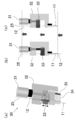
- FIG. 1A is a perspective view showing a state of attachment of a nerve electrode system of a device for using the nerve electrode system shown in FIG. 1, and FIG. 2B shows a state where an insert is moved to the most distal side with respect to a tube-type electrode.
- FIG. 4 is a side view showing the positions of the photostimulation portion and each electrode (Ch1 to 8) in the tube-type electrode when the photostimulation is given in the shallow portion in the in-vivo measurement test shown in FIG.
- FIG. 4A is a side view showing the positions of the photostimulation section and the electrodes (Ch1 to Ch8) in the tube-type electrode when the photostimulation is applied in the deep part in the in-vivo measurement test shown in FIG.
- each electrode Ch2-4, 6, 7
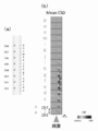
- a side view showing the position of each layer (Layer 1 to 6) of the nerve electrode in the brain, (b) 0 to 10 ms after light stimulation, (c) 10 to 20 ms after light stimulation, (d) 20 to 20 after light stimulation.
- the nerve electrode system 10 includes a tube electrode 11 and an insert 12.
- the tube-type electrode 11 has a plurality of electrodes 22 provided on the outer surface of an elongated cylindrical tube body 21 arranged in the length direction.
- the tube body 21 is made of translucent parylene and has a circular cross section.
- the tube-type electrode 11 performs metal wiring 23 corresponding to each electrode 22 in the range of one half of the outer surface of the tube body 21, and exposes a part of the metal wiring 23.
- Each electrode 22 is formed by covering the surface of the remaining metal wiring 23 with parylene.
- Each electrode 22 and the metal wiring 23 are made of gold (Au).
- the tube-type electrode 11 is manufactured using a microfabrication technique using parylene as a substrate.
- the insert 12 is made of stainless steel and is elongated and has a needle shape with a sharp tip.
- the insert 12 has an outer diameter that can be inserted into the tube-type electrode 11, and is provided so as to be movable in the tube-type electrode 11 along the length direction of the tube-type electrode 11.
- the insertion body 12 has a groove 24 formed on the side surface thereof extending along the length direction from the rear end to the front of the pointed tip.
- the insert 12 has a light irradiation means 25 made of an optical fiber inserted into the groove 24 along the groove 24.
- the light irradiation means 25 can irradiate light from the front-end
- the tip of the optical fiber is cut at an angle of 45 degrees, and a reflective film 26 made of Al or Al / Cr is formed on the cut surface.
- a reflective film 26 made of Al or Al / Cr is formed on the cut surface.
- the insert 12 is installed so that it may irradiate from the place where the metal wiring 23 of the tube-type electrode 11 does not exist in order to prevent the photoelectric effect at the time of light irradiation.
- a light source is connected to the rear end of the optical fiber.
- the tube-type electrode 11 has an inner diameter of 320 ⁇ m and an outer diameter of 360 ⁇ m.
- the electrodes 22 are composed of eight electrodes, each having a diameter of 25 ⁇ m and arranged at intervals of 200 ⁇ m.
- the diameter of the optical fiber of the light irradiation means 25 is 125 ⁇ m.
- FIG. 2 shows an insertion device 30 for using the nerve electrode system 10.
- the insertion device 30 includes a spindle straight type micrometer head (“MHK-15” manufactured by Mitutoyo Corporation) 31, a jig 32 to which the tube-type electrode 11 is fixed, and an insert 12.
- the micrometer head 31 has a non-operating portion fixed to the jig 32 and a moving tip portion fixed to the jig 33.
- the insertion device 30 is a tube in which the insert 12 fixed to the jig 33 is fixed to the jig 32 by moving the jig 33 with the micrometer head 31.
- the mold electrode 11 is configured to be movable along the length direction of the tube electrode 11.
- the insertion body 12 can be moved to a desired position of the tube-type electrode 11 by moving while checking the movement amount with the scale of the micrometer head 31. Thereby, the position of the light irradiation by the light irradiation means 25 can be adjusted.
- the nerve electrode system 10 is mainly used by being installed inside the brain in a state where the insert 12 is inserted into the tube electrode 11.
- Light stimulation can be performed on nerve cells in the brain by irradiating light toward the side of the tube-type electrode 11 with the light irradiation means 25 in a state of being installed inside the brain.
- the electrical signal from the nerve cell by the light stimulation can be measured by the plurality of electrodes 22 provided on the tube-type electrode 11, and can be used for elucidation of a local neural circuit.
- the nerve electrode system 10 can perform light irradiation by the light irradiation means 25 of the insert body 12 at an arbitrary position of the tube body 21 by moving the insert body 12 inside the tube electrode 11. For this reason, the freedom degree of the relative positional relationship between a light irradiation position and an electrode position is very high, and it can measure with a desired positional relationship. Thereby, it is possible to investigate in detail the relationship between each nerve cell in the depth direction of the brain, and to contribute to the elucidation of the structure and function in the depth direction of the brain.
- the nerve electrode system 10 can irradiate light at a plurality of locations with a single optical fiber, it is not necessary to increase the diameter of the insert 12 and it is possible to maintain a good insertion property with a small diameter. it can. Further, since no optical waveguide is used, coupling loss does not occur, and light irradiation can be performed with sufficient emission intensity. Since the insertion body 12 is needle-shaped, the nerve electrode system 10 can be easily inserted into the dura mater and the brain with the distal end of the insertion body 12 protruding from the tube electrode 11.
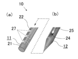
- the tube body 21 may be made of a material that is not translucent and may have a plurality of translucent windows 27 along the length direction. .
- the degree of freedom in the relative positional relationship between the light irradiation position and the electrode position is lower than in the case where the tube body 21 is made of a translucent material, but light irradiation is performed at the position of each window 27. It can be performed.
- the tube body 21 is made of polyimide.
- the translucent window 27 consists of three, each forms a square shape of 200 ⁇ m ⁇ 200 ⁇ m, and is arranged at intervals of 600 ⁇ m.
- the tube body 21 may have any shape such as a polygonal shape or a semicircular shape as long as the cross-sectional shape is not circular but it is not limited to an annular shape.
- the tube body 21 may have a different thickness depending on the location.
- the tube body 21 may be formed thin at the position where the light is irradiated, and thick at the position where each electrode 22 is attached.
- the tube body 21 may have, for example, an optical waveguide for light emission or light reception along the length direction so that various measurements can be performed.
- the insertion body 12 may constitute the light irradiation means 25 by using a polymer or the like in the groove 24 without using an optical fiber to form an optical waveguide.
- the insert 12 may use a plurality of optical fibers, optical waveguides, and rod lenses as the light irradiating means 25, so that a plurality of locations can be irradiated with light at the same time for more detailed analysis. it can.
- the insertion body 12 does not need to have a sharp tip unless insertion is necessary.
- the insert 12 may have a light receiving means.
- the light receiving means can receive reflected light by light irradiation and perform imaging.
- the reaction from the nerve cell by light stimulation can be acquired with light, and the result of a kind different from the measurement by the electrode 22 can also be obtained.
- the insert 12 may have a flow path. In this case, a drug or the like can be supplied into the brain through the flow path.
- the insert 12 may consist of an endoscope.
- an endoscope not only electrical measurement by light stimulation but also functions such as imaging built in the endoscope can be used at the same time, and highly accurate measurement and treatment can be performed.
- a test was performed in which the nerve electrode system 10 shown in FIG.
- a rat in which the channel rhodopsin ChR2 of the photoreceptor channel was expressed by gene transfer was used.
- measurement conditions measurement was performed in a shielded room, under anesthesia, and with the head fixed.
- KX anesthesia ketamine-xylazine anesthesia
- anesthesia was performed by injecting 100 mg / kg and 10 mg / kg into the peritoneal cavity, respectively.
- the insertion site was on the somatosensory area of the rat's brain (pregma right side 2.5mm, rostral side 2.5mm). At the time of insertion, the skull around the insertion site was shaved off with a handpiece.
- the insert 12 and the tube electrode 11 of the nerve electrode system 10 were inserted from the dura mater in the brain of the rat 41 to the cerebral cortex.
- the connector 35 of the insertion device 30 was connected from the amplifier 36 to a measuring instrument (“Omniplex” manufactured by Plexon Inc.) and a computer.
- a screw 42 was embedded in the skull on the cerebellum of the left hemisphere of the rat 41 and connected to a clip taken out from the connector 35 to be used as a potential reference.
- a laser diode light source with a variable intensity function connected to a power source 29 (manufactured by Kashiyama Kogyo Co., Ltd.) was used. Further, as light stimulation from the optical fiber of the light irradiation means 25, a pulse having a pulse width of 2 ms and a light intensity of 90 ⁇ W was applied at 2 Hz for 20 seconds.
- the electric signal obtained at each electrode 22 of the nerve electrode system 10 is amplified by an amplifier 36 by 250 times, and then the signal and noise are removed to obtain an LFP that is a potential generated by a synaptic current flowing outside the cell.
- a low-pass filter with an off frequency of 200 Hz was passed.
- the LFP thus obtained was recorded at a sampling frequency of 1 kHz.
- the current source density (CSD) analysis was performed from the obtained LFP.
- FIGS. 5 and 6 show the LFP obtained with each of the eight electrodes (Ch1 to Ch8) and the CSD analysis results obtained based on the LFP when light stimulation is applied in the shallow and deep parts of the brain. Show. Since Ch5 could not be measured, it was excluded in the CSD analysis (the same applies hereinafter). As shown in FIG. 5, when light stimulation was performed in the shallow part, an evoked potential was observed only in the shallow part. As shown in FIG. 6, when light stimulation was performed in the deep part, a large evoked potential was recorded in the deep part, and the evoked potential was recorded in the shallow part with a delay. At both stimulation positions, a sink (negative potential) is observed in the vicinity of the stimulation portion, and it is considered that ions have flowed into the cells due to light stimulation.
- FIG. 7 shows the results of CSD analysis when light stimulation was applied at 16 points (from ap to ap) from the deep to the shallow part of the brain.
- the horizontal axis represents time
- the vertical axis represents the CSD analysis result obtained based on the LFP obtained from each of the electrodes Ch1 to Ch8 for each light irradiation position.
- CSD analysis is performed 40 ms before and after light stimulation, and the analysis result is relatively displayed between the largest sink (negative potential) and the largest source (positive potential) during this period.
- a strong sink is observed only at the light stimulation positions e to g. Since the light stimulation positions e to g are considered to be located in the fifth layer (Layer 5) of the nerve electrode 22 in the brain, when stimulated in the fifth layer, the evoked potential is stronger than the other layers. It was confirmed that
- CSD for 0 to 10 ms after light stimulation CSD for 10 to 20 ms after light stimulation
- CSD for 20 to 30 ms after light stimulation CSD for 20 to 30 ms after light stimulation
- 30 to 40 ms after light stimulation The results of separating the CSDs are shown in FIG. 8B to 8E, the vertical axis represents the position of each electrode 22, and the horizontal axis represents the light stimulation position.
- the source (positive potential) is not shown.
- FIG. 8B As shown in FIG. 8B, at 0 to 10 ms after light stimulation, at deep stimulation positions from light stimulation positions a to i, a sync is recognized at Ch2 to 4, and at light stimulation positions k to p, synchronization is performed at Ch7. Was recognized. Further, a strong propagation potential was observed when stimulating with g from the light stimulation position e. As shown in FIG. 8 (c), it was recognized that the sink in the deep part became large in 10 to 20 ms after the light stimulation. As shown in FIG. 8 (d), a large sink was observed in Ch2 in the deep part 20-30 ms after light stimulation. As shown in FIG. 8 (e), at 30 to 40 ms after the light stimulation, a sink was also observed in the shallow portion at the deep stimulation position from the light stimulation position e to g.
- the nerve electrode system 10 can investigate in detail the relationship between each nerve cell in the depth direction of the brain, contributing to the elucidation of the structure and function in the depth direction of the brain. I can say that.
Landscapes
- Health & Medical Sciences (AREA)
- Life Sciences & Earth Sciences (AREA)
- Surgery (AREA)
- Molecular Biology (AREA)
- Animal Behavior & Ethology (AREA)
- Veterinary Medicine (AREA)
- Biophysics (AREA)
- Pathology (AREA)
- Engineering & Computer Science (AREA)
- Biomedical Technology (AREA)
- Heart & Thoracic Surgery (AREA)
- Medical Informatics (AREA)
- Public Health (AREA)
- General Health & Medical Sciences (AREA)
- Physics & Mathematics (AREA)
- Psychiatry (AREA)
- Psychology (AREA)
- Neurosurgery (AREA)
- Nuclear Medicine, Radiotherapy & Molecular Imaging (AREA)
- Optics & Photonics (AREA)
- Radiology & Medical Imaging (AREA)
- Measurement And Recording Of Electrical Phenomena And Electrical Characteristics Of The Living Body (AREA)
- Endoscopes (AREA)
- Electrotherapy Devices (AREA)
Abstract
【課題】刺入性が良く、十分な発光強度を有し、光照射位置と電極位置との間の相対的な位置関係の自由度が高く、局所の神経回路の解明に利用することができる神経電極システムを提供する。 【解決手段】チューブ型電極11が、細長い筒状のチューブ体21の外側面に、長さ方向に並んで設けられた複数の電極22を有している。チューブ体21は、透光性の素材で形成されている。挿入体12が、チューブ型電極11の内部に挿入可能かつ、チューブ型電極11の長さ方向に沿ってチューブ型電極11の内部を移動可能に設けられている。挿入体12は、チューブ型電極11に挿入したとき、チューブ型電極11の側方に向かって光を照射可能に設けられた光照射手段25を有している。
Description
本発明は、神経電極システムに関する。
脳では、神経細胞と呼ばれる細胞同士の間で電気信号のやりとりをする回路を構築し、情報を伝達処理している。この回路の構成や機能を解明するため、従来、脳に刺入し、高い時空間分解能で、同時に多数の神経細胞活動を電気的に計測できる神経電極が開発されている(例えば、特許文献1参照)。
また、局所の神経回路を解明するため、特定の神経細胞を刺激して、その神経細胞の反応による電気信号を計測する実験が行われている。特定の神経細胞を刺激する方法としては、近年、特定の神経細胞に光感受性のタンパク質を発現させることにより、より選択的に刺激できる手法が用いられている。このような実験に使用するために、多点で光刺激を行うとともに、その光刺激による神経細胞からの電気信号を計測するものとして、複数の光ファイバや光導波路を内蔵し、多点の電極を有する神経電極が開発されている(例えば、特許文献2、非特許文献1乃至3参照)。
S. Royer, B. V. Zemelman, M. Barbic, A. Losonczy, G. Buzsaki, J. C.Magee, "Multi-array silicon probes with integrated optical fibers: light-assisted perturbation and recording of local neural circuits in the behaving animal", European Journal of Neuroscience, 2010, 31, 12, p.2279-2291
A. N. Zorzos, E. S. Boyden, C. G. Fonstad, "Multiwaveguide implantable probe for light delivery to sets of distributed brain targets", Optics letters, 2010, 35, 24, p.4133-4135
S. Kanno, S. Lee, T. Harashima, T. Kuki, H. Kino, H. Mushiake, H. Yao, T. Tanaka, "Multiple optical stimulation to neuron using Si opto-neural probe with multiple optical waveguides and metal-cover for optogenetics", Engineering in Medicine and Biology Society (EMBC), 2013 35th Annual International Conference of the IEEE, IEEE, 2013
特許文献1に記載の神経電極は、神経細胞に刺激を与えることはできないため、神経細胞に刺激を与えてその反応を測定する際には、別の神経電極や装置などで神経細胞に刺激を与える必要がある。しかしながら、別の神経電極や装置などで刺激を与えると、その刺激位置から距離が離れてしまうため、局所の神経回路の解明に利用するのは困難であるという課題があった。
特許文献2や非特許文献1乃至3に記載の神経電極は、複数の光ファイバや光導波路により、多点で光刺激を行うことができるが、多点化のために光ファイバの本数を増加させると、電極の断面積が増加し、刺入性が低下するという課題があった。また、光導波路を使用すると多点化は容易であるが、光を入力する箇所での光導波路-ファイバ間のカップリングロスにより、十分な強度で発光することができない可能性があるという課題があった。また、特許文献2や非特許文献1乃至3に記載の神経電極では、光照射位置および電極位置が固定されているため、光照射位置と電極位置との間の相対的な位置関係の自由度が小さいという課題があった。
本発明は、このような課題に着目してなされたもので、刺入性が良く、十分な発光強度を有し、光照射位置と電極位置との間の相対的な位置関係の自由度が高く、局所の神経回路の解明に利用することができる神経電極システムを提供することを目的とする。
上記目的を達成するために、本発明に係る神経電極システムは、細長い筒状のチューブ体の外側面に長さ方向に並んで設けられた複数の電極を有するチューブ型電極と、前記チューブ型電極の内部に挿入可能かつ前記チューブ型電極の長さ方向に沿って前記チューブ型電極の内部を移動可能に設けられた挿入体とを有し、前記チューブ体は少なくとも一部が透光性を有し、前記挿入体は、前記チューブ型電極に挿入したとき、前記チューブ型電極の側方に向かって光を照射可能に設けられた光照射手段を有することを特徴とする。
本発明に係る神経電極システムは、挿入体をチューブ型電極に挿入した状態で、脳や脊髄、眼球の網膜、抹消神経など、活動電位が発生、伝搬する部位に設置して使用される。なお、以下では、測定対象が脳であるものとして説明する。脳の内部に設置された状態で、光照射手段でチューブ型電極の側方に向かって光を照射することにより、脳内の神経細胞に対して光刺激を行うことができる。また、その光刺激による神経細胞からの電気信号を、チューブ型電極に設けられた複数の電極で計測することができ、局所の神経回路の解明に利用することができる。
本発明に係る神経電極システムは、挿入体をチューブ型電極の内部で移動させることにより、任意の位置から光刺激を行うことができる。また、挿入体に複数の光照射手段を設けることにより、同時に複数の位置から光刺激を行うことができる。これにより、脳の深さ方向における各神経細胞間の関係性を詳細に調べることができ、脳の深さ方向の構造や機能の解明に寄与することができる。
このように、本発明に係る神経電極システムは、電極位置に対して光照射位置を動かすことができ、光照射位置と電極位置との間の相対的な位置関係の自由度が高い。光照射手段としては、例えば、光ファイバや光導波路、ロッドレンズなどを利用することができる。光ファイバを利用する場合には、光ファイバ1本で、複数箇所で光照射を行うことができるため、挿入体の径を大きくする必要がなく、小さい径で刺入性を良い状態に維持することができる。また、カップリングロスが発生する場合には、光導波路を利用する必要がなく、十分な発光強度で光照射を行うことができる。なお、光ファイバや光導波路、ロッドレンズを複数利用してもよく、これにより複数箇所を同時に光照射することができ、より詳細な分析を行うことができる。
本発明に係る神経電極システムで、前記チューブ体は、透光性の素材で形成されていることが好ましい。この場合、チューブ体の任意の位置で、挿入体の光照射手段により光照射を行うことができる。このため、光照射位置と電極位置との間の相対的な位置関係の自由度が非常に高く、所望の位置関係で測定を行うことができる。チューブ体は、透光性であればいかなる素材から成っていてもよく、例えば、ガラス製やポリマー製、特にポリパラキシリレン(パリレン)製である。また、前記チューブ体は、長さ方向に沿って複数の透光性の窓を有していてもよい。この場合、光照射位置と電極位置との間の相対的な位置関係の自由度は低くなるが、各窓の位置で光照射を行うことができる。
本発明に係る神経電極システムで、チューブ体は、断面形状が環状であればよく、その環の形状は、円形や多角形、半円形など、いかなる形状であってもよい。また、チューブ体は、場所によって厚みが異なっていてもよい。例えば、透光性のチューブ体の光を照射する位置では薄く形成され、各電極が取り付けられている位置では厚く形成されていてもよい。また、チューブ体は、複数の電極の他に、様々な計測を行えるよう、例えば、長さ方向に沿って発光または受光用の光導波路などを有していてもよい。
本発明に係る神経電極システムで、前記挿入体は、細長く、先端が尖った針状を成していてもよく、先端が尖っていなくともよい。挿入体が針状を成す場合には、挿入体をチューブ型電極に挿入し、チューブ型電極から先端を突出させた状態で、硬膜および脳に刺入することができる。また、挿入体は、長さ方向に沿った溝を有し、その溝に光ファイバを入れて光照射手段を構成してもよい。また、その溝にポリマーなどを入れて光導波路を形成し、光照射手段を構成してもよい。
本発明に係る神経電極システムで、前記挿入体は、受光手段を有していてもよい。この場合、受光手段により、光照射による反射光を受光し、イメージングを行うことができる。また、光刺激による神経細胞からの反応を光で取得することができ、電極による測定とは異なる種類の結果を得ることもできる。また、挿入体は、流路を有していてもよい。この場合、流路を通して脳内に薬剤などを供給することができる。
本発明に係る神経電極システムで、前記挿入体は、内視鏡から成っていてもよい。この場合、光刺激による電気計測だけでなく、内視鏡に内蔵されたイメージング等の機能を同時に使用することができ、精度の高い測定や治療を行うことができる。
本発明によれば、刺入性が良く、十分な発光強度を有し、光照射位置と電極位置との間の相対的な位置関係の自由度が高く、局所の神経回路の解明に利用することができる神経電極システムを提供することができる。
以下、図面に基づいて、本発明の実施の形態について説明する。
図1乃至図8は、本発明の実施の形態の神経電極システムを示している。
図1に示すように、神経電極システム10は、チューブ型電極11と挿入体12とを有している。
図1乃至図8は、本発明の実施の形態の神経電極システムを示している。
図1に示すように、神経電極システム10は、チューブ型電極11と挿入体12とを有している。
図1(a)に示すように、チューブ型電極11は、細長い筒状のチューブ体21の外側面に、長さ方向に並んで設けられた複数の電極22を有している。チューブ体21は、透光性のパリレンから形成され、断面形状が円環状を成している。図1(d)に示すように、チューブ型電極11は、チューブ体21の外側面の片側半分の範囲に、各電極22に対応した金属配線23を行い、その金属配線23の一部を露出させて残りの金属配線23の表面をパリレンで覆うことにより、各電極22が形成されている。なお、各電極22および金属配線23は、金(Au)で形成されている。チューブ型電極11は、パリレンを基板として、マイクロファブリケーション技術を利用して製造されている。
図1(b)に示すように、挿入体12は、ステンレス製で、細長く、先端が尖った針状を成している。挿入体12は、チューブ型電極11の内部に挿入可能な外径を有し、チューブ型電極11の長さ方向に沿ってチューブ型電極11の内部を移動可能に設けられている。挿入体12は、側面に、長さ方向に沿って、後端から先端の尖った部分の手前まで伸びる溝24が形成されている。また、挿入体12は、その溝24に沿って、溝24の内部に挿入された光ファイバから成る光照射手段25を有している。
図1(c)に示すように、光照射手段25は、光ファイバの先端から、溝24の開口に向かって、挿入体12の長さ方向に対して直交する方向に光を照射可能に、光ファイバの先端を斜め45度に切断し、その切断面にAl製またはAl/Cr製の反射膜26が形成されている。これにより、図1(d)に示すように、挿入体12は、チューブ型電極11に挿入したとき、チューブ型電極11の側方に向かって、透光性のチューブ体21を通して光を照射可能になっている。なお、挿入体12は、光照射時の光電効果を防ぐために、チューブ型電極11の金属配線23がない場所から照射するよう設置されている。また、光ファイバの後端には、光源が接続されている。
なお、図1に示す具体的な一例では、チューブ型電極11は、内径が320μm、外径が360μmである。電極22は、8つから成り、それぞれ直径が25μmで、200μm間隔で配置されている。また、光照射手段25の光ファイバの径は、125μmである。
図2に、神経電極システム10を使用するための挿入デバイス30を示す。図2に示すように、挿入デバイス30は、スピンドル直進式のマイクロメータヘッド(ミツトヨ株式会社製「MHK-15」)31と、チューブ型電極11が固定されるジグ32と、挿入体12が固定されるジグ33と、チューブ型電極11の各電極22の配線に接続される接続用基板34と、接続用基板34に電気的に接続するためのコネクタ35とを有している。マイクロメータヘッド31は、稼働しない箇所がジグ32に固定され、移動する先端部がジグ33に固定されている。
図2(b)および(c)に示すように、挿入デバイス30は、マイクロメータヘッド31でジグ33を移動させることにより、ジグ33に固定された挿入体12が、ジグ32に固定されたチューブ型電極11に対して、チューブ型電極11の長さ方向に沿って移動可能に構成されている。また、マイクロメータヘッド31の目盛で移動量を確認しながら移動することにより、チューブ型電極11の所望の位置に挿入体12を移動可能になっている。これにより、光照射手段25による光照射の位置を調整可能になっている。
次に、作用について説明する。
神経電極システム10は、挿入体12をチューブ型電極11に挿入した状態で、主に脳の内部に設置して使用される。脳の内部に設置された状態で、光照射手段25でチューブ型電極11の側方に向かって光を照射することにより、脳内の神経細胞に対して光刺激を行うことができる。また、その光刺激による神経細胞からの電気信号を、チューブ型電極11に設けられた複数の電極22で計測することができ、局所の神経回路の解明に利用することができる。
神経電極システム10は、挿入体12をチューブ型電極11に挿入した状態で、主に脳の内部に設置して使用される。脳の内部に設置された状態で、光照射手段25でチューブ型電極11の側方に向かって光を照射することにより、脳内の神経細胞に対して光刺激を行うことができる。また、その光刺激による神経細胞からの電気信号を、チューブ型電極11に設けられた複数の電極22で計測することができ、局所の神経回路の解明に利用することができる。
神経電極システム10は、挿入体12をチューブ型電極11の内部で移動させることにより、チューブ体21の任意の位置で、挿入体12の光照射手段25により光照射を行うことができる。このため、光照射位置と電極位置との間の相対的な位置関係の自由度が非常に高く、所望の位置関係で測定を行うことができる。これにより、脳の深さ方向における各神経細胞間の関係性を詳細に調べることができ、脳の深さ方向の構造や機能の解明に寄与することができる。
神経電極システム10は、光ファイバ1本で、複数箇所で光照射を行うことができるため、挿入体12の径を大きくする必要がなく、小さい径で刺入性を良い状態に維持することができる。また、光導波路を利用しないため、カップリングロスが発生せず、十分な発光強度で光照射を行うことができる。神経電極システム10は、挿入体12が針状であるため、挿入体12の先端をチューブ型電極11から突出させた状態で、硬膜および脳に容易に刺入することができる。
なお、図3に示すように、神経電極システム10で、チューブ体21は、透光性ではない素材から成り、長さ方向に沿って複数の透光性の窓27を有していてもよい。この場合、チューブ体21が透光性の素材から成る場合と比べて、光照射位置と電極位置との間の相対的な位置関係の自由度は低くなるが、各窓27の位置で光照射を行うことができる。図3に示す具体的な一例では、チューブ体21はポリイミド製である。また、透光性の窓27は3つから成り、それぞれ200μm×200μmの正方形状を成し、600μm間隔で配置されている。
また、チューブ体21は、断面形状が円環状でなくとも、環状であればよく、その環の形状は、多角形や半円形など、いかなる形状であってもよい。また、チューブ体21は、場所によって厚みが異なっていてもよい。例えば、チューブ体21の光を照射する位置では薄く形成され、各電極22が取り付けられている位置では厚く形成されていてもよい。また、チューブ体21は、複数の電極22の他に、様々な計測を行えるよう、例えば、長さ方向に沿って発光または受光用の光導波路などを有していてもよい。
また、神経電極システム10で、挿入体12は、光ファイバを使用せず、溝24にポリマーなどを入れて光導波路を形成し、光照射手段25を構成してもよい。また、挿入体12は、光照射手段25として、光ファイバや光導波路、ロッドレンズを複数利用してもよく、これにより複数箇所を同時に光照射することができ、より詳細な分析を行うことができる。また、挿入体12は、刺入性が必要なければ、先端が尖っていなくともよい。
また、挿入体12は、受光手段を有していてもよい。この場合、受光手段により、光照射による反射光を受光し、イメージングを行うことができる。また、光刺激による神経細胞からの反応を光で取得することができ、電極22による測定とは異なる種類の結果を得ることもできる。また、挿入体12は、流路を有していてもよい。この場合、流路を通して脳内に薬剤などを供給することができる。
また、挿入体12は、内視鏡から成っていてもよい。この場合、光刺激による電気計測だけでなく、内視鏡に内蔵されたイメージング等の機能を同時に使用することができ、精度の高い測定や治療を行うことができる。
[生体内での計測試験]
図1に示す神経電極システム10を生体内に刺入して、光刺激による電気信号を計測する試験を行った。測定対象として、遺伝子導入により、光受容チャネルのチャネルロドプシンChR2を発現させたラットを用いた。測定条件として、シールド室内、麻酔下、頭部固定状態で測定を行った。麻酔には、ケタミン-キシラジン麻酔(KX麻酔)を用い、それぞれ100mg/kg、10mg/kgを腹腔に注入して麻酔を行った。また、刺入箇所は、ラットの脳の体性感覚野上(プレグマ右側方2.5mm、吻側2.5mm)とした。刺入時には、刺入部位周辺の頭骨を、ハンドピースで削って取り除いた。
図1に示す神経電極システム10を生体内に刺入して、光刺激による電気信号を計測する試験を行った。測定対象として、遺伝子導入により、光受容チャネルのチャネルロドプシンChR2を発現させたラットを用いた。測定条件として、シールド室内、麻酔下、頭部固定状態で測定を行った。麻酔には、ケタミン-キシラジン麻酔(KX麻酔)を用い、それぞれ100mg/kg、10mg/kgを腹腔に注入して麻酔を行った。また、刺入箇所は、ラットの脳の体性感覚野上(プレグマ右側方2.5mm、吻側2.5mm)とした。刺入時には、刺入部位周辺の頭骨を、ハンドピースで削って取り除いた。
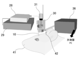
図4に示すように、図2に示す挿入デバイス30を用いて、神経電極システム10の挿入体12およびチューブ型電極11を、ラット41の脳内の硬膜から大脳皮質まで刺入した。試験時には、挿入デバイス30のコネクタ35をアンプ36から計測機器(Plexon inc.製「Omniplex」)およびコンピュータに接続した。また、ラット41の左半球の小脳上の頭骨にネジ42を埋め込み、コネクタ35から取り出したクリップと接続して電位参照として用いた。
光照射手段25の光ファイバに接続される光源28として、電源29に接続された強度可変機能付きのレーザーダイオード光源(檜山工業株式会社製)を用いた。また、光照射手段25の光ファイバからの光刺激として、パルス幅2ms、光強度90μWのパルスを、2Hzで20秒間与えた。
神経電極システム10の各電極22で得られる電気信号は、アンプ36で250倍に増幅後、信号やノイズを除去し、細胞外を流れるシナプス電流によりつくられる電位であるLFPを得るために、カットオフ周波数200Hzのローパスフィルタを通した。こうして得られたLFPを、サンプリング周波数1kHzで記録した。また、得られたLFPから、電流源密度(CSD)解析を行った。
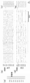
脳の浅部および深部で光刺激を与えたときの、8つの各電極(Ch1~Ch8)で得られたLFP、および、LFPに基づいて得られたCSD解析の結果を図5および図6に示す。なお、Ch5は計測できなかったため、CSD解析では除外している(以下同じ)。図5に示すように、浅部で光刺激を行った場合には、浅い部分のみに誘発電位が観察された。また、図6に示すように、深部で光刺激を行った場合には、深部に大きな誘発電位が記録されるとともに、浅部でも遅れて誘発電位が記録された。どちらの刺激位置でも、刺激部の近傍でシンク(陰性電位)が認められ、光刺激により細胞内へのイオンの流入があったと考えられる。
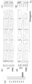
次に、脳の深部から浅部まで、16箇所(a~pまで)で光刺激を与えたときのCSD解析の結果を、図7に示す。図7(b)の横軸は時間、縦軸は光照射位置ごとに、各電極Ch1~Ch8で得られたLFPに基づいて得られたCSD解析結果を示している。CSD解析は、光刺激の前後40msで行い、この間で最も大きいシンク(陰性電位)と最も大きいソース(陽性電位)との間で、その解析結果を相対的に表示している。
図7に示すように、光刺激位置eからgにおいてのみ強いシンクが観察されている。この光刺激位置eからgは、脳内の神経電極22の第5層(Layer 5)に位置していたと考えられることから、この第5層で刺激したときには、他の層よりも強い誘発電位を示すことが確認された。
次に、光刺激位置による誘発電位の伝播を評価するため、光刺激後0~10msのCSD、光刺激後10~20msのCSD、光刺激後20~30msのCSD、および光刺激後30~40msのCSDを分離した結果を、図8に示す。図8(b)~(e)の縦軸は各電極22の位置、横軸は光刺激位置を示している。また、ソース(陽性電位)の表示は省略している。
図8(b)に示すように、光刺激後0~10msでは、光刺激位置aからiの深い刺激位置では、Ch2~4でシンクが認められ、光刺激位置kからpでは、Ch7でシンクが認められた。また、光刺激位置eからgで刺激したときには、強い伝播電位が認められた。図8(c)に示すように、光刺激後10~20msでは、深部でのシンクが大きくなっているのが認められた。図8(d)に示すように、光刺激後20~30msでは、深部のCh2で、大きなシンクが認められた。図8(e)に示すように、光刺激後30~40msでは、光刺激位置eからgの深い刺激位置では、浅部にもシンクが認められた。
この結果から、脳内の神経電極22の第5層(Layer 5)を刺激したとき、強い伝播電位を示すことが確認された。このことから、脳内の神経電極22の第5層を刺激したときには、強いシンクを示し、浅部に伝播したものと考えられる。また、他の層を刺激したときには、弱いシンクを示し、それ以外の層には伝播しなかったと考えられる。
以上の生体内での試験結果から、神経電極システム10は、脳の深さ方向における各神経細胞間の関係性を詳細に調べることができ、脳の深さ方向の構造や機能の解明に寄与することができるといえる。
10 神経電極システム
11 チューブ型電極
21 チューブ体
22 電極
23 金属配線
12 挿入体
24 溝
25 光照射手段
26 反射膜
27 窓
28 光源
29 電源
30 挿入デバイス
31 マイクロメータヘッド
32,33 ジグ
34 接続用基板
35 コネクタ
36 アンプ
41 ラット
42 ネジ
11 チューブ型電極
21 チューブ体
22 電極
23 金属配線
12 挿入体
24 溝
25 光照射手段
26 反射膜
27 窓
28 光源
29 電源
30 挿入デバイス
31 マイクロメータヘッド
32,33 ジグ
34 接続用基板
35 コネクタ
36 アンプ
41 ラット
42 ネジ
Claims (6)
- 細長い筒状のチューブ体の外側面に長さ方向に並んで設けられた複数の電極を有するチューブ型電極と、
前記チューブ型電極の内部に挿入可能かつ前記チューブ型電極の長さ方向に沿って前記チューブ型電極の内部を移動可能に設けられた挿入体とを有し、
前記チューブ体は少なくとも一部が透光性を有し、
前記挿入体は、前記チューブ型電極に挿入したとき、前記チューブ型電極の側方に向かって光を照射可能に設けられた光照射手段を有することを
特徴とする神経電極システム。 - 前記チューブ体は、透光性の素材で形成されていることを特徴とする請求項1記載の神経電極システム。
- 前記チューブ体は、長さ方向に沿って複数の透光性の窓を有することを特徴とする請求項1記載の神経電極システム。
- 前記挿入体は、細長く、先端が尖った針状を成していることを特徴とする請求項1乃至3のいずれか1項に記載の神経電極システム。
- 前記挿入体は、受光手段を有することを特徴とする請求項1乃至4のいずれか1項に記載の神経電極システム。
- 前記挿入体は、内視鏡から成ることを特徴とする請求項1乃至3のいずれか1項に記載の神経電極システム。
Priority Applications (1)
| Application Number | Priority Date | Filing Date | Title |
|---|---|---|---|
| JP2017525200A JP6913368B2 (ja) | 2015-06-17 | 2016-06-10 | 神経電極システム |
Applications Claiming Priority (2)
| Application Number | Priority Date | Filing Date | Title |
|---|---|---|---|
| JP2015122014 | 2015-06-17 | ||
| JP2015-122014 | 2015-06-17 |
Publications (1)
| Publication Number | Publication Date |
|---|---|
| WO2016204084A1 true WO2016204084A1 (ja) | 2016-12-22 |
Family
ID=57545863
Family Applications (1)
| Application Number | Title | Priority Date | Filing Date |
|---|---|---|---|
| PCT/JP2016/067338 Ceased WO2016204084A1 (ja) | 2015-06-17 | 2016-06-10 | 神経電極システム |
Country Status (2)
| Country | Link |
|---|---|
| JP (1) | JP6913368B2 (ja) |
| WO (1) | WO2016204084A1 (ja) |
Cited By (4)
| Publication number | Priority date | Publication date | Assignee | Title |
|---|---|---|---|---|
| CN113925518A (zh) * | 2021-09-23 | 2022-01-14 | 中国科学院深圳先进技术研究院 | 一种喷射原位生成的微创神经接口及其制备方法和应用 |
| WO2022181133A1 (ja) * | 2021-02-25 | 2022-09-01 | 株式会社カネカ | 内視鏡用光照射装置 |
| CN116784866A (zh) * | 2023-06-13 | 2023-09-22 | 华南师范大学 | 用于脑部研究的植入装置及使用方法 |
| CN118340570A (zh) * | 2024-06-18 | 2024-07-16 | 北京智冉医疗科技有限公司 | 电极发光平台和具有其的电极植入设备 |
Citations (3)
| Publication number | Priority date | Publication date | Assignee | Title |
|---|---|---|---|---|
| WO2010038393A1 (ja) * | 2008-09-30 | 2010-04-08 | 国立大学法人奈良先端科学技術大学院大学 | 脳内情報計測装置 |
| JP2011036360A (ja) * | 2009-08-10 | 2011-02-24 | Tohoku Univ | 神経用多機能電極 |
| JP2014033851A (ja) * | 2012-08-09 | 2014-02-24 | Nakatani Sangyo Co Ltd | 神経用電極 |
Family Cites Families (1)
| Publication number | Priority date | Publication date | Assignee | Title |
|---|---|---|---|---|
| ITTO20130603A1 (it) * | 2013-07-17 | 2015-01-18 | Fond Istituto Italiano Di Tecnologia | Strumento optogenetico per l'indirizzamento multiplo ed indipendente di finestre ottiche patternate |
-
2016
- 2016-06-10 JP JP2017525200A patent/JP6913368B2/ja active Active
- 2016-06-10 WO PCT/JP2016/067338 patent/WO2016204084A1/ja not_active Ceased
Patent Citations (3)
| Publication number | Priority date | Publication date | Assignee | Title |
|---|---|---|---|---|
| WO2010038393A1 (ja) * | 2008-09-30 | 2010-04-08 | 国立大学法人奈良先端科学技術大学院大学 | 脳内情報計測装置 |
| JP2011036360A (ja) * | 2009-08-10 | 2011-02-24 | Tohoku Univ | 神経用多機能電極 |
| JP2014033851A (ja) * | 2012-08-09 | 2014-02-24 | Nakatani Sangyo Co Ltd | 神経用電極 |
Non-Patent Citations (2)
| Title |
|---|
| SHUNSUKE TAMAKI ET AL.: "Development and Evaluation of tube-shaped neural probe with working channel for optical stimulation", THE 51ST ANNUAL CONFERENCE OF JAPANESE SOCIETY FOR MEDICAL AND BIOLOGICAL ENGINEERING PROGRAM SHOROKUSHU, 2012 * |
| SHUNSUKE TAMAKI ET AL.: "Development of tube-shaped neural probe with working channel for optical stimulation", THE 50TH ANNUAL CONFERENCE OF JAPANESE SOCIETY FOR MEDICAL AND BIOLOGICAL ENGINEERING PROGRAM SHOROKUSHU, 2011 * |
Cited By (5)
| Publication number | Priority date | Publication date | Assignee | Title |
|---|---|---|---|---|
| WO2022181133A1 (ja) * | 2021-02-25 | 2022-09-01 | 株式会社カネカ | 内視鏡用光照射装置 |
| CN113925518A (zh) * | 2021-09-23 | 2022-01-14 | 中国科学院深圳先进技术研究院 | 一种喷射原位生成的微创神经接口及其制备方法和应用 |
| CN116784866A (zh) * | 2023-06-13 | 2023-09-22 | 华南师范大学 | 用于脑部研究的植入装置及使用方法 |
| CN116784866B (zh) * | 2023-06-13 | 2023-12-01 | 华南师范大学 | 用于脑部研究的植入装置及使用方法 |
| CN118340570A (zh) * | 2024-06-18 | 2024-07-16 | 北京智冉医疗科技有限公司 | 电极发光平台和具有其的电极植入设备 |
Also Published As
| Publication number | Publication date |
|---|---|
| JPWO2016204084A1 (ja) | 2018-04-26 |
| JP6913368B2 (ja) | 2021-08-04 |
Similar Documents
| Publication | Publication Date | Title |
|---|---|---|
| Jiang et al. | Spatially expandable fiber-based probes as a multifunctional deep brain interface | |
| Jun et al. | Fully integrated silicon probes for high-density recording of neural activity | |
| Wang et al. | Integrated device for combined optical neuromodulation and electrical recording for chronic in vivo applications | |
| Stark et al. | Diode probes for spatiotemporal optical control of multiple neurons in freely moving animals | |
| US10405750B2 (en) | Nonradiative voltage-sensitive dye for imaging neuronal action potential | |
| Park et al. | One-step optogenetics with multifunctional flexible polymer fibers | |
| Tufail et al. | Ultrasonic neuromodulation by brain stimulation with transcranial ultrasound | |
| Buzsáki et al. | Tools for probing local circuits: high-density silicon probes combined with optogenetics | |
| Pothof et al. | Chronic neural probe for simultaneous recording of single-unit, multi-unit, and local field potential activity from multiple brain sites | |
| JP5843201B2 (ja) | 小動物用の脳測定用電極ユニットとそれを用いた測定システム | |
| US20170007824A1 (en) | Minimally invasive splaying microfiber electrode array and methods of fabricating and implanting the same | |
| US20160038770A1 (en) | Focused transcranial ultrasound systems and methods for using them | |
| JP6913368B2 (ja) | 神経電極システム | |
| US20240057943A1 (en) | Multilayer and bouquet fiber-based neural probes and methods of making and uses thereof | |
| Fiáth et al. | Large-scale recording of thalamocortical circuits: in vivo electrophysiology with the two-dimensional electronic depth control silicon probe | |
| Dai et al. | Modified toolbox for optogenetics in the nonhuman primate | |
| Wang et al. | Dense packed drivable optrode array for precise optical stimulation and neural recording in multiple-brain regions | |
| Jendritza et al. | Multi-area recordings and optogenetics in the awake, behaving marmoset | |
| Tooker et al. | Towards a large-scale recording system: Demonstration of polymer-based penetrating array for chronic neural recording | |
| ITTO20130603A1 (it) | Strumento optogenetico per l'indirizzamento multiplo ed indipendente di finestre ottiche patternate | |
| Zhang et al. | Electrode arrays for detecting and modulating deep brain neural information in primates: A review | |
| Bermudez-Contreras et al. | High-performance, inexpensive setup for simultaneous multisite recording of electrophysiological signals and mesoscale voltage imaging in the mouse cortex | |
| Allard et al. | Neuronavigation-guided transcranial acoustoelectric brain imaging: a new modality for high resolution electrical brain mapping | |
| Richie et al. | Fabrication and validation of sub-cellular carbon fiber electrodes | |
| Gong et al. | Non-invasive hybrid ultrasound stimulation of visual cortex in vivo |
Legal Events
| Date | Code | Title | Description |
|---|---|---|---|
| 121 | Ep: the epo has been informed by wipo that ep was designated in this application |
Ref document number: 16811558 Country of ref document: EP Kind code of ref document: A1 |
|
| ENP | Entry into the national phase |
Ref document number: 2017525200 Country of ref document: JP Kind code of ref document: A |
|
| NENP | Non-entry into the national phase |
Ref country code: DE |
|
| 122 | Ep: pct application non-entry in european phase |
Ref document number: 16811558 Country of ref document: EP Kind code of ref document: A1 |