WO2016203881A1 - Dispositif de décodage arithmétique et dispositif de codage arithmétique - Google Patents
Dispositif de décodage arithmétique et dispositif de codage arithmétique Download PDFInfo
- Publication number
- WO2016203881A1 WO2016203881A1 PCT/JP2016/064339 JP2016064339W WO2016203881A1 WO 2016203881 A1 WO2016203881 A1 WO 2016203881A1 JP 2016064339 W JP2016064339 W JP 2016064339W WO 2016203881 A1 WO2016203881 A1 WO 2016203881A1
- Authority
- WO
- WIPO (PCT)
- Prior art keywords
- information
- context index
- unit
- context
- partition
- Prior art date
Links
Images


Classifications
-
- H—ELECTRICITY
- H04—ELECTRIC COMMUNICATION TECHNIQUE
- H04N—PICTORIAL COMMUNICATION, e.g. TELEVISION
- H04N19/00—Methods or arrangements for coding, decoding, compressing or decompressing digital video signals
- H04N19/10—Methods or arrangements for coding, decoding, compressing or decompressing digital video signals using adaptive coding
- H04N19/102—Methods or arrangements for coding, decoding, compressing or decompressing digital video signals using adaptive coding characterised by the element, parameter or selection affected or controlled by the adaptive coding
- H04N19/13—Adaptive entropy coding, e.g. adaptive variable length coding [AVLC] or context adaptive binary arithmetic coding [CABAC]
-
- H—ELECTRICITY
- H04—ELECTRIC COMMUNICATION TECHNIQUE
- H04N—PICTORIAL COMMUNICATION, e.g. TELEVISION
- H04N19/00—Methods or arrangements for coding, decoding, compressing or decompressing digital video signals
- H04N19/10—Methods or arrangements for coding, decoding, compressing or decompressing digital video signals using adaptive coding
- H04N19/102—Methods or arrangements for coding, decoding, compressing or decompressing digital video signals using adaptive coding characterised by the element, parameter or selection affected or controlled by the adaptive coding
- H04N19/119—Adaptive subdivision aspects, e.g. subdivision of a picture into rectangular or non-rectangular coding blocks
-
- H—ELECTRICITY
- H04—ELECTRIC COMMUNICATION TECHNIQUE
- H04N—PICTORIAL COMMUNICATION, e.g. TELEVISION
- H04N19/00—Methods or arrangements for coding, decoding, compressing or decompressing digital video signals
- H04N19/10—Methods or arrangements for coding, decoding, compressing or decompressing digital video signals using adaptive coding
- H04N19/134—Methods or arrangements for coding, decoding, compressing or decompressing digital video signals using adaptive coding characterised by the element, parameter or criterion affecting or controlling the adaptive coding
- H04N19/136—Incoming video signal characteristics or properties
-
- H—ELECTRICITY
- H04—ELECTRIC COMMUNICATION TECHNIQUE
- H04N—PICTORIAL COMMUNICATION, e.g. TELEVISION
- H04N19/00—Methods or arrangements for coding, decoding, compressing or decompressing digital video signals
- H04N19/10—Methods or arrangements for coding, decoding, compressing or decompressing digital video signals using adaptive coding
- H04N19/169—Methods or arrangements for coding, decoding, compressing or decompressing digital video signals using adaptive coding characterised by the coding unit, i.e. the structural portion or semantic portion of the video signal being the object or the subject of the adaptive coding
- H04N19/17—Methods or arrangements for coding, decoding, compressing or decompressing digital video signals using adaptive coding characterised by the coding unit, i.e. the structural portion or semantic portion of the video signal being the object or the subject of the adaptive coding the unit being an image region, e.g. an object
- H04N19/176—Methods or arrangements for coding, decoding, compressing or decompressing digital video signals using adaptive coding characterised by the coding unit, i.e. the structural portion or semantic portion of the video signal being the object or the subject of the adaptive coding the unit being an image region, e.g. an object the region being a block, e.g. a macroblock
-
- H—ELECTRICITY
- H04—ELECTRIC COMMUNICATION TECHNIQUE
- H04N—PICTORIAL COMMUNICATION, e.g. TELEVISION
- H04N19/00—Methods or arrangements for coding, decoding, compressing or decompressing digital video signals
- H04N19/10—Methods or arrangements for coding, decoding, compressing or decompressing digital video signals using adaptive coding
- H04N19/189—Methods or arrangements for coding, decoding, compressing or decompressing digital video signals using adaptive coding characterised by the adaptation method, adaptation tool or adaptation type used for the adaptive coding
- H04N19/196—Methods or arrangements for coding, decoding, compressing or decompressing digital video signals using adaptive coding characterised by the adaptation method, adaptation tool or adaptation type used for the adaptive coding being specially adapted for the computation of encoding parameters, e.g. by averaging previously computed encoding parameters
-
- H—ELECTRICITY
- H04—ELECTRIC COMMUNICATION TECHNIQUE
- H04N—PICTORIAL COMMUNICATION, e.g. TELEVISION
- H04N19/00—Methods or arrangements for coding, decoding, compressing or decompressing digital video signals
- H04N19/70—Methods or arrangements for coding, decoding, compressing or decompressing digital video signals characterised by syntax aspects related to video coding, e.g. related to compression standards
-
- H—ELECTRICITY
- H04—ELECTRIC COMMUNICATION TECHNIQUE
- H04N—PICTORIAL COMMUNICATION, e.g. TELEVISION
- H04N19/00—Methods or arrangements for coding, decoding, compressing or decompressing digital video signals
- H04N19/90—Methods or arrangements for coding, decoding, compressing or decompressing digital video signals using coding techniques not provided for in groups H04N19/10-H04N19/85, e.g. fractals
- H04N19/91—Entropy coding, e.g. variable length coding [VLC] or arithmetic coding
Definitions
- the present invention relates to an arithmetic decoding device that decodes encoded data that has been arithmetically encoded, and an image decoding device that includes the arithmetic encoding device.
- the present invention also relates to an arithmetic encoding device that generates encoded data that has been arithmetically encoded, and an image encoding device that includes the arithmetic encoding device.
- a moving image encoding device that generates encoded data by encoding the moving image, and a moving image that generates a decoded image by decoding the encoded data
- An image decoding device is used.
- Non-Patent Document 1 Specific examples of the moving image encoding method include H.264. H.264 / MPEG-4. Examples include AVC and a scheme proposed by HEVC (High-Efficiency Video Coding) as a successor codec (Non-Patent Document 1).
- images (pictures) constituting a moving image are slices obtained by dividing the image, coding units obtained by dividing the slices (coding units (Coding Unit; CU), and a hierarchical structure composed of prediction units (Prediction Unit; PU) and transform units (Transform Unit; TU), which are blocks obtained by dividing a coding unit,
- the data is encoded / decoded for each block.
- a predicted image is usually generated based on a local decoded image obtained by encoding / decoding an input image, and the predicted image is generated from the input image (original image).
- a prediction residual obtained by subtraction (sometimes referred to as “difference image” or “residual image”) is encoded.
- examples of the method for generating a predicted image include inter-screen prediction (inter prediction) and intra-screen prediction (intra prediction).
- Non-Patent Document 1 a technique is known in which encoding units and transform units having a high degree of freedom are selected using quadtree partitioning to balance the amount of code and accuracy. Based on the value of a flag (CU partition flag) indicating whether or not the encoding unit having the block size is to be subjected to quadtree partitioning for the maximum coding unit of 64 ⁇ 64 block size, quadtree partitioning is performed. By repeating recursively up to the minimum encoding unit, it is possible to divide into encoding units up to block sizes of 64 ⁇ 64, 32 ⁇ 32, 16 ⁇ 16, and 8 ⁇ 8.
- CU partition flag indicating whether or not the encoding unit having the block size is to be subjected to quadtree partitioning for the maximum coding unit of 64 ⁇ 64 block size
- Non-Patent Document 2 discloses quadtree partitioning of an encoding unit when the maximum encoding unit size is expanded from 64 ⁇ 64 to a maximum of 512 ⁇ 512 block size.
- quadtree partitioning is recursively performed to the minimum coding unit based on the coding unit CU partition flag having the block size. By repeating, it is possible to divide into encoding units up to 512 ⁇ 512, 256 ⁇ 256, 128 ⁇ 128, 64 ⁇ 64, 32 ⁇ 32, 16 ⁇ 16, and 8 ⁇ 8 block sizes.
- Non-Patent Document 2 the context index derivation process for specifying a context related to a CU partitioning flag indicating whether or not to divide the encoding unit into quadtrees is complicated when the maximum size of the encoding unit is extended, and There is a problem that the number of contexts increases. More specifically, Non-Patent Document 2 refers to the division depth of the target CU and the division depth of the surrounding decoded (encoded) CU adjacent to the target CU to derive the context index related to the CU partition flag.
- the arithmetic decoding apparatus performs encoding by referring to a context index deriving unit that specifies a context, a context specified by the context index, and a bypass flag.
- An arithmetic decoding device comprising: an arithmetic code decoding means for decoding a Bin sequence consisting of one or a plurality of Bins from data; and a CU division identifier decoding means for decoding a syntax value of a CU division identifier for the target CU from the Bin sequence.
- the context index deriving unit derives a context index related to the CU partition identifier based on the partition depth of the target CU and the partition depth of one or more decoded adjacent CUs.
- the arithmetic coding apparatus specifies a CU partition identifier encoding unit that encodes a syntax value of a CU partition identifier for a target CU into a Bin sequence, and a context A context index deriving unit that performs encoding of a Bin sequence including one or a plurality of bins with reference to a context specified by the context index and a bypass flag.
- the context index deriving unit derives a context index related to the CU partition identifier based on the partition depth of the target CU and the partition depth of one or more decoded neighboring CUs, thereby encoding the CU partition identifier. While maintaining the efficiency, the increase in the number of contexts related to the CU partition identifier is suppressed, and the context index derivation process related to the CU partition identifier is simplified.
- the context index deriving unit derives the context index related to the CU partition identifier based on the partition depth of the target CU and the partition depth of one or more encoded adjacent CUs, thereby In order to suppress the increase in the number of contexts related to the CU partition identifier and simplify the context index derivation process related to the CU partition identifier while maintaining the efficiency of the conversion, the effect of reducing the amount of encoding processing is achieved.
- FIG. 3 is a diagram illustrating a data configuration of encoded data generated by a video encoding device according to an embodiment of the present invention and decoded by the video decoding device, wherein (a) to (d) are pictures, respectively. It is a figure which shows a layer, a slice layer, a tree block layer, and a CU layer. It is a flowchart explaining schematic operation
- PU partition types are 2N ⁇ 2N, 2N ⁇ N, 2N ⁇ nU, 2N ⁇ nD, N ⁇ 2N, nL ⁇ 2N, nR ⁇ 2N, and N ⁇ N, respectively.
- the partition shape in case is shown.
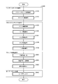
- CTU information decoding S1300, CT information decoding S1400 which concerns on one Embodiment of this invention.
- A L, LB, T, TR.
- FIG. 1 It is a functional block diagram shown about the structural example of the arithmetic encoding part with which the encoding data generation part which concerns on one Embodiment of this invention is provided. It is the figure shown about the structure of the transmitter which mounts the said moving image encoder, and the receiver which mounts the said moving image decoder.
- (A) shows a transmitting apparatus equipped with a moving picture coding apparatus
- (b) shows a receiving apparatus equipped with a moving picture decoding apparatus. It is the figure shown about the structure of the recording device which mounts the said moving image encoder, and the reproducing
- (A) shows a recording apparatus equipped with a moving picture coding apparatus
- (b) shows a reproduction apparatus equipped with a moving picture decoding apparatus.
- FIG. 2 is a functional block diagram showing a schematic configuration of the moving picture decoding apparatus 1.
- the video decoding device 1 and the video encoding device 2 shown in FIG. 2 are implemented with the technology adopted in HEVC (High Efficiency Video Coding).
- the video encoding device 2 generates encoded data # 1 by entropy encoding a syntax value defined to be transmitted from the encoder to the decoder in these video encoding schemes. .
- Context-adaptive variable-length coding CAVLC
- CABAC context-adaptive binary arithmetic coding
- the context is an encoding / decoding situation (context), and is determined by past encoding / decoding results of related syntax.
- Examples of the related syntax include various syntaxes related to intra prediction and inter prediction, various syntaxes related to luminance (Luma) and color difference (Chroma), and various syntaxes related to CU (Coding Unit encoding unit) size.
- CABAC the binary position to be encoded / decoded in binary data (binary string) corresponding to the syntax may be used as the context.
- CABAC CABAC
- binarization processing is performed on syntax that can take multiple values such as a prediction mode and a conversion coefficient, and binary data obtained by this binarization processing is adaptive according to the occurrence probability.
- arithmetically encoded Specifically, multiple buffers that hold the occurrence probability of binary values (0 or 1) are prepared, one buffer is selected according to the context, and arithmetic coding is performed based on the occurrence probability recorded in the buffer I do. Further, by updating the occurrence probability of the buffer based on the binary value to be decoded / encoded, an appropriate occurrence probability can be maintained according to the context.
- the moving picture decoding apparatus 1 receives encoded data # 1 obtained by encoding a moving picture by the moving picture encoding apparatus 2.
- the video decoding device 1 decodes the input encoded data # 1 and outputs the video # 2 to the outside.
- the configuration of the encoded data # 1 will be described below.
- the encoded data # 1 exemplarily includes a sequence and a plurality of pictures constituting the sequence.
- FIG. 3 shows the hierarchical structure below the picture layer in the encoded data # 1.
- 3A to 3E respectively show a picture layer that defines a picture PICT, a slice layer that defines a slice S, a tree block layer that defines a coding tree block (Coding Tree) CTB, and a coding tree. It is a figure which shows the encoding tree layer which prescribes
- Picture layer In the picture layer, a set of data referred to by the video decoding device 1 for decoding a picture PICT to be processed (hereinafter also referred to as a target picture) is defined. As shown in FIG. 3A, the picture PICT includes a picture header PH and slices S 1 to S NS (NS is the total number of slices included in the picture PICT).
- the picture header PH includes a coding parameter group referred to by the video decoding device 1 in order to determine a decoding method of the target picture.
- the picture header PH is also called a picture parameter set (PPS).
- slice layer In the slice layer, a set of data referred to by the video decoding device 1 for decoding the slice S to be processed (also referred to as a target slice) is defined. As shown in FIG. 3B, the slice S includes a slice header SH and tree blocks CTU 1 to CTU NC (where NC is the total number of tree blocks included in the slice S).
- the slice header SH includes a coding parameter group that the moving image decoding apparatus 1 refers to in order to determine a decoding method of the target slice.
- Slice type designation information (slice_type) for designating a slice type is an example of an encoding parameter included in the slice header SH.
- the slice types that can be specified by the slice type specification information include (1) I slice that uses only intra prediction at the time of encoding, (2) P slice that uses single prediction or intra prediction at the time of encoding, ( 3) B-slice using single prediction, bi-prediction, or intra prediction at the time of encoding may be used.
- the slice header SH may include a filter parameter referred to by a loop filter (not shown) included in the video decoding device 1.
- the tree block layer a set of data referred to by the video decoding device 1 for decoding a processing target tree block CTU (hereinafter also referred to as a target tree block) is defined.
- the tree block CTB is a block that divides a slice (picture) into a fixed size.
- image data pixels
- not only the image data of the tree block and region but also information for decoding the image data (for example, division information or the like) ) May also be called a tree unit.
- it is simply referred to as a tree block CTU without distinction.
- the coding tree, the coding unit, and the like are handled including not only the image data of the corresponding region but also information (for example, division information) for decoding the image data.
- the tree block CTU includes a tree block header CTUH and coding unit information CQT.
- coding unit information CQT coding unit information
- the tree block CTU is a unit that divides a slice (picture) into a fixed size.
- the tree block CTU has a coding tree (CT).
- CT coding tree
- the coding tree (CT) is divided by recursive quadtree division.
- the tree structure obtained by this recursive quadtree partitioning and its nodes are hereinafter referred to as a coding tree.
- a unit corresponding to a leaf that is a node at the end of the coding tree is referred to as a coding node.
- the encoding node is also referred to as an encoding unit (CU). That is, the highest-level coding tree CT is CTU (CQT), and the terminal coding tree CT is CU.
- CQT CTU
- CU terminal coding tree
- the coding unit information CU 1 to CU NL is information corresponding to each coding node (coding unit) obtained by recursively dividing the tree block CTU into quadtrees.
- the root of the coding tree is associated with the tree block CTU.
- the tree block CTU (CQT) is associated with the highest node of the tree structure of the quadtree partition that recursively includes a plurality of coding nodes (CT).
- each coding node is half the size of the coding node to which the coding node directly belongs (that is, the unit of the node one layer higher than the coding node).
- the size that each coding node can take is the size designation information of the coding node and the maximum hierarchy depth (maximum hierarchical depth) (or also referred to as the maximum division depth) included in the sequence parameter set SPS of the coded data # 1.
- the maximum hierarchy depth maximum hierarchical depth
- MaxCqtDepth 4
- the encoding nodes in the hierarchy below the tree block CTU have five sizes, that is, the hierarchy depth.
- the tree block header CTUH includes an encoding parameter referred to by the video decoding device 1 in order to determine a decoding method of the target tree block. Specifically, as shown in (c) of FIG. 3, an SAO that specifies a filtering method for the target tree block is included.
- Information included in the CTU, such as CTUH, is referred to as coding tree unit information (CTU information).
- the coding tree CT has tree block division information SP that is information for dividing a tree block.
- the tree block division information SP is a CU division identifier that is an identifier indicating whether or not the entire target tree block or a partial area of the tree block is divided into four.
- split_cu_idx may be used.
- the CU split identifier split_cu_idx is 1, the coding tree CT is further divided into four coding trees CT.
- split_cu_idx it means that the coding tree CT is a terminal node that is not split.
- CT information coding tree information
- the CT information may include parameters applied in the encoding tree and the encoding units below it, in addition to the CU split flag split_cu_idx indicating whether or not to further divide the encoding tree.
- the coding tree CT may be further divided into binary trees in the vertical direction (2N ⁇ N, which will be described later). Further, the association between the CU partitioning identifier split_cu_idx and each partitioning method can be changed within a feasible range.
- CU layer In the CU layer, a set of data referred to by the video decoding device 1 for decoding a CU to be processed (hereinafter also referred to as a target CU) is defined.
- the encoding node is a node at the root of a prediction tree (PT) and a transformation tree (TT).
- PT prediction tree
- TT transformation tree
- the encoding node is divided into one or a plurality of prediction blocks, and the position and size of each prediction block are defined.
- the prediction block is one or a plurality of non-overlapping areas constituting the encoding node.
- the prediction tree includes one or a plurality of prediction blocks obtained by the above division.
- Prediction processing is performed for each prediction block.
- a prediction block that is a unit of prediction is also referred to as a prediction unit (PU).
- intra prediction There are roughly two types of division in the prediction tree: intra prediction and inter prediction.
- inter prediction there are 2N ⁇ 2N (the same size as the encoding node), 2N ⁇ N, N ⁇ 2N, N ⁇ N, and the like.
- the encoding node is divided into one or a plurality of transform blocks, and the position and size of each transform block are defined.
- the transform block is one or a plurality of non-overlapping areas constituting the encoding node.
- the conversion tree includes one or a plurality of conversion blocks obtained by the above division.
- transform processing is performed for each conversion block.
- the transform block which is a unit of transform is also referred to as a transform unit (TU).
- the coding unit information CU specifically includes CU information (skip flag SKIP, CU prediction type information Pred_type), PT information PTI, and TT information TTI.
- the skip flag SKIP is a flag (skip_flag) indicating whether or not the skip mode is applied to the target CU.
- the value of the skip flag SKIP is 1, that is, when the skip mode is applied to the target CU.
- the PT information PTI and the TT information TTI in the coding unit information CU are omitted. Note that the skip flag SKIP is omitted for the I slice.
- the CU prediction type information Pred_type includes CU prediction method information (PredMode) and PU partition type information (PartMode).
- the CU prediction method information specifies whether to use a skip mode, intra prediction (intra CU), or inter prediction (inter CU) as a predicted image generation method for each PU included in the target CU. Is.
- a CU prediction mode the types of skip, intra prediction, and inter prediction in the target CU are referred to as a CU prediction mode.
- the PU partition type information designates a PU partition type that is a pattern of partitioning the target coding unit (CU) into each PU.
- PartMode designates a PU partition type that is a pattern of partitioning the target coding unit (CU) into each PU.
- PU division dividing the target coding unit (CU) into each PU according to the PU division type in this way.
- the PU partition type information may be, for example, an index indicating the type of PU partition pattern, and the shape and size of each PU included in the target prediction tree, and the target prediction tree The position may be specified. Note that PU partitioning is also called a prediction unit partitioning type.
- selectable PU partition types differ depending on the CU prediction method and the CU size. Furthermore, the PU partition types that can be selected are different in each case of inter prediction and intra prediction. Details of the PU partition type will be described later.
- the value of CU prediction method information (PredMode) and the value of PU partition type information (PartMode) are CU partition identifier (split_cu_idx), skip flag (skip_flag), merge flag (merge_flag; described later), CU It may be specified by an index (cu_split_pred_part_mode) that specifies a combination of prediction method information (PredMode) and PU partition type information (PartMode).
- An index such as cu_split_pred_part_mode is also called a combined syntax (or joint code).
- the PT information PTI is information related to the PT included in the target CU.
- the PT information PTI is a set of information on each of one or more PUs included in the PT.
- the PT information PTI is referred to when the moving image decoding apparatus 1 generates a predicted image.
- the PT information PTI includes PU information PUI 1 to PUI NP (NP is the total number of PUs included in the target PT) including prediction information and the like in each PU.
- the prediction information PUI includes intra prediction information or inter prediction information depending on which prediction method the prediction type information Pred_mode specifies.
- a PU to which intra prediction is applied is also referred to as an intra PU
- a PU to which inter prediction is applied is also referred to as an inter PU.
- the inter prediction information includes an encoding parameter that is referred to when the video decoding device 1 generates an inter prediction image by inter prediction.
- inter prediction parameters examples include a merge flag (merge_flag), a merge index (merge_idx), an estimated motion vector index (mvp_idx), a reference image index (ref_idx), an inter prediction flag (inter_pred_flag), and a motion vector residual (mvd). Is mentioned.
- the intra prediction information includes an encoding parameter that is referred to when the video decoding device 1 generates an intra predicted image by intra prediction.
- Examples of intra prediction parameters include an estimated prediction mode flag, an estimated prediction mode index, and a residual prediction mode index.
- a PCM mode flag indicating whether to use the PCM mode may be encoded.
- the prediction process (intra), the conversion process, and the entropy encoding process are omitted.
- the TT information TTI is information regarding the TT included in the CU.
- the TT information TTI is a set of information regarding each of one or a plurality of TUs included in the TT, and is referred to when the moving image decoding apparatus 1 decodes residual data.
- a TU may be referred to as a block.
- the TT information TTI includes an information CU residual flag CBP_TU indicating whether or not the target CU includes residual data, and a TT that specifies a division pattern of the target CU into each transform block. It includes division information SP_TU and TU information TUI 1 to TUI NT (NT is the total number of blocks included in the target CU).
- the target CU does not include residual data, that is, TT information TTI.
- the target CU includes residual data, that is, TT information TTI.
- the CU residual flag CBP_TU is, for example, a residual root flag rqt_root_cbf (Residual
- the TT division information SP_TU is information for determining the shape and size of each TU included in the target CU and the position within the target CU.
- the TT partition information SP_TU can be realized by a TU partition flag (split_transform_flag) indicating whether or not the target node is to be partitioned and a TU depth (TU hierarchy, trafoDepth) indicating the depth of the partition.
- the TU partition flag split_transform_flag is a flag indicating whether or not a transform block to be transformed (inverse transform) is to be divided. In the case of division, transform (inverse transform, inverse quantization, quantization) is performed using a smaller block. Done.
- each TU obtained by the division can take a size from 32 ⁇ 32 pixels to 4 ⁇ 4 pixels.
- the TU information TUI 1 to TUI NT are individual information regarding one or more TUs included in the TT.
- the TU information TUI includes a quantized prediction residual.
- Each quantized prediction residual is encoded data generated by the video encoding device 2 performing the following processes 1 to 3 on a target block that is a processing target block.
- Process 1 DCT transform (Discrete Cosine Transform) of the prediction residual obtained by subtracting the prediction image from the encoding target image;
- Process 2 Quantize the transform coefficient obtained in Process 1;
- Process 3 Variable length coding is performed on the transform coefficient quantized in Process 2;
- the PU partition type includes the following eight patterns in total, assuming that the size of the target CU is 2N ⁇ 2N pixels. That is, 4 symmetric splittings of 2N ⁇ 2N pixels, 2N ⁇ N pixels, N ⁇ 2N pixels, and N ⁇ N pixels, and 2N ⁇ nU pixels, 2N ⁇ nD pixels, nL ⁇ 2N pixels, And four asymmetric splittings of nR ⁇ 2N pixels.
- N 2 m (m is an arbitrary integer of 1 or more).
- an area obtained by dividing a symmetric CU is also referred to as a partition.
- FIG. 5 specifically show the positions of the boundaries of PU division in the CU for each division type.
- (a) in the figure shows a 2N ⁇ 2N PU partition type that does not perform CU partitioning.
- (b), (c), and (d) in the figure show the shapes of partitions when the PU partition types are 2N ⁇ N, 2N ⁇ nU, and 2N ⁇ nD, respectively. ing.
- partitions when the PU partition type is 2N ⁇ N, 2N ⁇ nU, and 2N ⁇ nD are collectively referred to as a horizontally long partition.
- (e), (f), and (g) in FIG. 5 respectively show the partition shapes when the PU partition types are N ⁇ 2N, nL ⁇ 2N, and nR ⁇ 2N.
- partitions when the PU partition type is N ⁇ 2N, nL ⁇ 2N, and nR ⁇ 2N are collectively referred to as a vertically long partition.
- the horizontally long partition and the vertically long partition are collectively referred to as a rectangular partition.
- (h) in the figure shows the shape of the partition when the PU partition type is N ⁇ N.
- the PU partitioning types (a) and (h) in the figure are also referred to as square partitioning based on the shape of the partition.
- the PU partition types (b) to (g) in the figure are also referred to as non-square partitions.
- the numbers given to the respective regions indicate the identification numbers of the regions, and the processing is performed on the regions in the order of the identification numbers. That is, the identification number represents the scan order of the area.
- the upper left is the reference point (origin) of the CU.
- Partition type for inter prediction In the inter PU, seven types other than N ⁇ N ((h) in the figure) are defined among the above eight division types. Note that the above four asymmetric partitions may be called AMP (Asymmetric Motion Partition).
- AMP Asymmetric Motion Partition
- a CU divided by asymmetric partitions includes partitions having different shapes or sizes. Symmetric partitioning may also be referred to as a symmetric partition.
- a CU divided by a symmetric partition includes a partition having the same shape and size.
- a 128 ⁇ 128 pixel inter-CU includes 128 ⁇ 128 pixels, 128 ⁇ 64 pixels, 64 ⁇ 128 pixels, 64 ⁇ 64 pixels, 128 ⁇ 32 pixels, 128 ⁇ 96 pixels, 32 ⁇ 128 pixels, and 96 ⁇ It is possible to divide into 128-pixel inter PUs.
- Partition type for intra prediction In the intra PU, the following two types of division patterns are defined. That is, there are a division pattern 2N ⁇ 2N in which the target CU is not divided, that is, the target CU itself is handled as one PU, and a pattern N ⁇ N in which the target CU is symmetrically divided into four PUs.
- the division patterns (a) and (h) can be taken in the example shown in FIG.
- an 128 ⁇ 128 pixel intra CU can be divided into 128 ⁇ 128 pixel and 64 ⁇ 64 pixel intra PUs.
- the coding unit information CU may include an intra partition mode (intra_part_mode) for specifying a PU partition type (PartMode).
- intra_part_mode an intra partition mode for specifying a PU partition type (PartMode).
- the video decoding device 1 generates a predicted image for each PU, generates a decoded image # 2 by adding the generated predicted image and a prediction residual decoded from the encoded data # 1, and generates The decoded image # 2 is output to the outside.
- An encoding parameter is a parameter referred in order to generate a prediction image.
- the encoding parameters include PU size and shape, block size and shape , And residual data between the original image and the predicted image.
- side information a set of all information excluding the residual data among the information included in the encoding parameter is referred to as side information.
- a picture (frame), a slice, a tree block, a block, and a PU to be decoded are referred to as a target picture, a target slice, a target tree block, a target block, and a target PU, respectively.
- the size of the tree block is, for example, 64 ⁇ 64 pixels
- the size of the PU is, for example, 64 ⁇ 64 pixels, 32 ⁇ 32 pixels, 16 ⁇ 16 pixels, 8 ⁇ 8 pixels, 4 ⁇ 4 pixels, or the like.
- these sizes are merely examples, and the sizes of the tree block and PU may be other than the sizes shown above.
- FIG. 2 is a functional block diagram showing a schematic configuration of the moving picture decoding apparatus 1.
- the moving picture decoding apparatus 1 includes a decoding module 10, a CU information decoding unit 11, a PU information decoding unit 12, a TU information decoding unit 13, a predicted image generation unit 14, an inverse quantization / inverse conversion unit 15, A frame memory 16 and an adder 17 are provided.
- FIG. 4 is a flowchart illustrating a schematic operation of the video decoding device 1.
- the decoding module 10 decodes parameter set information such as SPS and PPS from the encoded data # 1.
- the decoding module 10 decodes the slice header (slice information) from the encoded data # 1.
- the decoding module 10 derives a decoded image of each CTB by repeating the processing from S1300 to S4000 for each CTB included in the target picture.
- the CU information decoding unit 11 decodes the encoded tree unit information (CTU information) from the encoded data # 1.
- the CU information decoding unit 11 decodes the encoded tree information (CT information) from the encoded data # 1.
- the CU information decoding unit 11 decodes encoded unit information (CU information) from the encoded data # 1.
- the PU information decoding unit 12 decodes the prediction unit information (PT information PTI) from the encoded data # 1.
- the TU information decoding unit 13 decodes the conversion unit information (TT information TTI) from the encoded data # 1.
- the predicted image generation unit 14 generates a predicted image based on the PT information PTI for each PU included in the target CU.
- the inverse quantization / inverse transform unit 15 performs an inverse quantization / inverse transformation process on each TU included in the target CU based on the TT information TTI.
- the decoding module 10 uses the adder 17 to add the prediction image Pred supplied from the prediction image generation unit 14 and the prediction residual D supplied from the inverse quantization / inverse transformation unit 15, A decoded image P for the target CU is generated.
- the decoding module 10 applies a loop filter such as a deblocking filter and a sample adaptive filter (SAO) to the decoded image P.
- a loop filter such as a deblocking filter and a sample adaptive filter (SAO)
- the decoding module 10 performs a decoding process for decoding a syntax value from binary. More specifically, the decoding module 10 decodes a syntax value encoded by an entropy encoding method such as CABAC and CAVLC based on encoded data and a syntax type supplied from a supplier, Returns the decrypted syntax value to the supplier.
- an entropy encoding method such as CABAC and CAVLC
- the sources of encoded data and syntax type are the CU information decoding unit 11, the PU information decoding unit 12, and the TU information decoding unit 13.
- the CU information decoding unit 11 uses the decoding module 10 to perform decoding processing at the tree block and CU level on the encoded data # 1 for one frame input from the moving image encoding device 2. Specifically, the CU information decoding unit 11 decodes CTU information, CT information, CU information, PT information PTI, and TT information TTI from the encoded data # 1 according to the following procedure.
- the CU information decoding unit 11 refers to various headers included in the encoded data # 1, and sequentially separates the encoded data # 1 into slices and tree blocks.
- the various headers include (1) information about the method of dividing the target picture into slices, and (2) information about the size, shape, and position of the tree block belonging to the target slice. .
- the CU information decoding unit 11 decodes the tree block division information SP_CTU included in the tree block header CTUH as CT information, and divides the target tree block into CUs.
- the CU information decoding unit 11 acquires coding unit information (hereinafter referred to as CU information) corresponding to the CU obtained by the division.
- the CU information decoding unit 11 performs the decoding process of the CU information corresponding to the target CU, with each CU included in the tree block as the target CU in order.
- the CU information decoding unit 11 demultiplexes the TT information TTI related to the conversion tree obtained for the target CU and the PT information PTI related to the prediction tree obtained for the target CU.
- the TT information TTI includes the TU information TUI corresponding to the TU included in the conversion tree as described above. Further, as described above, the PT information PTI includes the PU information PUI corresponding to the PU included in the target prediction tree.
- the CU information decoding unit 11 supplies the PT information PTI obtained for the target CU to the PU information decoding unit 12. Further, the CU information decoding unit 11 supplies the TT information TTI obtained for the target CU to the TU information decoding unit 13.
- FIG. 1 is a flowchart for explaining the schematic operation of the CU information decoding unit 11 (CTU information decoding S1300, CT information decoding S1400) according to an embodiment of the invention.
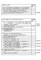
- FIG. 17 is a diagram showing a configuration example of a syntax table of CU information according to an embodiment of the present invention.
- the CT layer (CT depth) cqtDepth 0 in the highest layer and increases one by one as the lower layer becomes deeper, but this is not restrictive.
- the size of these blocks is handled in logarithm with 2 as the base. However, it is not limited to this.
- the block size is 4, 8, 16, 32, 64, 128, 256, 2, 3, 4, 5, 6, 7, 8 are logarithmic values, respectively.
- the CU information decoding unit 11 recursively decodes the coding tree TU (coding_quadtree) (S1400).
- the CU information decoding unit 11 decodes the highest-level (root) coding tree coding_quadtree (xCtb, yCtb, CtbLog2SizeY, 0) (SYN 1400).
- XCtb and yCtb are the upper left coordinates of the CTB
- CtbLog2SizeY is the CTB block size (for example, 64, 128, 256).
- the CU information decoding unit 11 determines whether or not the logarithmic CU size log2CbSize is larger than a predetermined minimum CU size MinCbLog2SizeY (minimum conversion block size) (SYN1411). When the logarithmic CU size log2CbSize is larger than MinCbLog2SizeY, the process proceeds to S1421, and otherwise, the process proceeds to S1422.
- MinCbLog2SizeY minimum conversion block size
- the CU information decoding unit 11 decodes a CU split flag (split_cu_flag) that is a syntax element shown in SYN1421.
- the logarithmic CU size log2CbSize is equal to or smaller than MinCbLog2SizeY
- the CU information decoding unit 11 starts from the encoded data # 1 when the CU partition identifier split_cu_idx does not appear in the encoded data # 1. Decoding of the CU partition identifier split_cu_idx is omitted, and the CU partition identifier split_cu_idx is derived as 0.
- the CU information decoding unit 11 decodes one or more coding trees included in the target coding tree.
- the four lower-order coding trees CT of the logarithmic CT size log2CbSize ⁇ 1 and the position (x0, y0), (x1, y0), (x0, y1), (x1, y1) at the CT hierarchy cqtDepth + 1 Is decrypted.
- the CU information decoding unit 11 continues the CT decoding process S1400 started from S1411 even in the lower coding tree CT.
- coding_quadtree (x0, y0, log2CbSize-1, cqtDepth + 1)
- SYN1441A coding_quadtree (x1, y0, log2CbSize-1, cqtDepth + 1)
- SYN1441B coding_quadtree (x0, y1, log2CbSize-1, cqtDepth + 1)
- SYN1441C coding_quadtree (x1, y1, log2CbSize-1, cqtDepth + 1)
- x0 and y0 are derived by adding the upper left coordinates of the target coding tree, and x1 and y1 by adding 1/2 of the target CT size (1 ⁇ log2CbSize) to the CT coordinates as in the following expression. Coordinates.
- CU information decoding unit 11 decodes the coding unit CUcoding_unit (x0, y0, log2CbSize) (SYN 1450).
- x0 and y0 are the coordinates of the encoding unit.
- log2CbSize which is the size of the coding tree, is equal to the size of the coding unit.
- the PU information decoding unit 12 uses the decoding module 10 to perform decoding processing at the PU level for the PT information PTI supplied from the CU information decoding unit 11. Specifically, the PU information decoding unit 12 decodes the PT information PTI by the following procedure.
- the PU information decoding unit 12 refers to the PU partition type information Part_type, and determines the PU partition type in the target prediction tree. Subsequently, the PU information decoding unit 12 performs a decoding process of PU information corresponding to the target PU, with each PU included in the target prediction tree as a target PU in order.
- the PU information decoding unit 12 performs a decoding process on each parameter used for generating a predicted image from PU information corresponding to the target PU.
- the PU information decoding unit 12 supplies the PU information decoded for the target PU to the predicted image generation unit 14.
- FIG. 1600 is a flowchart for explaining the schematic operation of PU information decoding shown in S1600.
- FIG. 18 is a diagram illustrating a configuration example of a syntax table of CU information, PT information PTI, and TT information TTI according to an embodiment of the present invention.
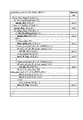
- FIG. 19 is a diagram showing a configuration example of a syntax table of PT information PTI according to an embodiment of the present invention.
- the CU information decoding unit 11 decodes the skip flag skip_flag from the encoded data # 1.
- the PU information decoding unit 12 omits decoding of the CU prediction method information PredMode and the PU partition type information PartMode that are the prediction type Pred_type from the encoded data # 1. In this case, inter prediction and non-division (2N ⁇ 2N) are derived.
- the TU information decoding unit 13 omits the decoding process of the TT information TTI from the encoded data # 1 shown in S1700, and the target CU is divided into TUs. None, and the quantization prediction residual TransCoeffLevel [] [] of the target CU is derived to be 0.
- the PU information decoding unit 12 decodes the CU prediction method information PredMode (syntax element pred_mode_flag) from the encoded data # 1.
- S1621 PU information decoding unit 12 decodes PU partition type information PartMode (syntax element part_mode) from encoded data # 1.
- the PU information decoding unit 12 decodes each PU information included in the target CU from the encoded data # 1 according to the number of PU divisions indicated by the PU division type information Part_type.
- the following one PU information PUI with one CU as one PU is decoded.
- prediction_unit (x0, y0, nCbS, nCbS) (SYN1631B) prediction_unit (x0, y0 + (nCbS / 2), nCbS, nCbS / 2) (SYN1631C)
- Nx2N the following two PU information PUIs that divide the CU into left and right are decoded.
- prediction_unit (x0, y0, nCbS, nCbS) (SYN1631D) prediction_unit (x0 + (nCbS / 2), y0, nCbS / 2, nCbS) (SYN1631E)
- NxN the following four PU information PUIs that divide the CU into four equal parts are decoded.
- prediction_unit (x0, y0, nCbS, nCbS) (SYN1631F) prediction_unit (x0 + (nCbS / 2), y0, nCbS / 2, nCbS) (SYN1631G) prediction_unit (x0, y0 + (nCbS / 2), nCbS, nCbS / 2) (SYN1631H) prediction_unit (x0 + (nCbS / 2), y0 + (nCbS / 2), nCbS / 2, nCbS / 2) (SYN1631I) S1632 When the skip flag is 1, the PU partition type is set to 2Nx2N, and one PU information PUI is decoded.
- the TU information decoding unit 13 uses the decoding module 10 to perform decoding processing at the TU level for the TT information TTI supplied from the CU information decoding unit 11. Specifically, the TU information decoding unit 13 decodes the TT information TTI by the following procedure.
- the TU information decoding unit 13 refers to the TT division information SP_TU and divides the target conversion tree into nodes or TUs. Note that the TU information decoding unit 13 recursively performs TU division processing if it is specified that further division is performed for the target node.
- the TU information decoding unit 13 executes the decoding process of the TU information corresponding to the target TU, with each TU included in the target prediction tree as the target TU in order.
- the TU information decoding unit 13 performs a decoding process on each parameter used for restoring the transform coefficient from the TU information corresponding to the target TU.
- the TU information decoding unit 13 supplies the TU information decoded for the target TU to the inverse quantization / inverse transform unit 15.
- the TU information decoding unit 13 performs the following operation as shown in FIG.
- This figure is a flowchart for explaining the schematic operation of the TU information decoding unit 13 (TT information decoding S1700) according to an embodiment of the invention.
- the TU information decoding unit 13 uses a CU residual flag rqt_root_cbf (syntax element shown in SYN 1711) indicating whether or not the target CU has a residual other than 0 (quantized prediction residual) from the encoded data # 1. ).
- the TU information decoding unit 13 initializes variables for managing the recursively divided conversion tree. Specifically, as shown in the following equation, 0 is set in the TU hierarchy trafoDepth indicating the hierarchy of the transformation tree, and the encoding unit size (here, logarithmic TU size log2TrafoSize) is set as the TU size (logarithmic TU size log2TrafoSize). Logarithmic CT size log2CbSize) is set.
- the TU information decoding unit 13 recursively decodes the transformation tree TU (transform_tree) (S1720).
- the transformation tree TU is divided so that the size of a leaf node (transformation block) obtained by recursive division becomes a predetermined size. That is, the division is performed so that the maximum size of conversion MaxTbLog2SizeY or less and the minimum size MinTbLog2SizeY or more are obtained.
- TU partition flag decoding unit included in the TU information decoding unit 13 has a target TU size (for example, log TU size log2TrafoSize) within a predetermined conversion size range (here, MaxTbLog2SizeY or less and MinTbLog2SizeY)
- a target TU size for example, log TU size log2TrafoSize
- a predetermined conversion size range here, MaxTbLog2SizeY or less and MinTbLog2SizeY
- the TU partition flag decoding unit included in the TU information decoding unit 13 decodes the TU partition flag split_transform_flag according to the condition of S1721.
- the TU partition flag decoding unit included in the TU information decoding unit 13 is otherwise the TU partition flag split_transform_flag from the encoded data # 1 when split_transform_flag does not appear in the encoded data # 1.
- the logarithm TU size log2TrafoSize is larger than the maximum TU size MaxTbLog2SizeY
- the log TU size log2TrafoSize is the minimum TU size MaxTbLog2SizeY.
- the TU hierarchy trafoDepth is equal to the maximum TU hierarchy MaxTrafoDepth)
- the TU partition flag decoder included in the TU information decoder 13 includes a transform tree included in the target coding unit CU. Is decrypted.
- the TU information decoding unit 13 continues the TT information decoding process S1700 started from S1711 in the lower-order coding tree TT.
- transform_tree (x0, y0, x0, y0, log2TrafoSize-1, trafoDepth + 1, 0)
- SYN1741A transform_tree (x1, y0, x0, y0, log2TrafoSize-1, trafoDepth + 1, 1)
- SYN1741B transform_tree (x0, y1, x0, y0, log2TrafoSize-1, trafoDepth + 1, 2)
- SYN1741C transform_tree (x1, y1, x0, y0, log2TrafoSize-1, trafoDepth + 1, 3)
- x0 and y0 are the upper left coordinates of the target conversion tree
- x1 and y1 are 1/2 of the target TU size (1 ⁇ log2TrafoSize) at the conversion tree coordinates (x0, y0) as shown in the following expression.
- the TU information decoding unit 13 decodes a TU residual flag indicating whether the target TU includes a residual.
- the luminance residual flag cbf_luma indicating whether the luminance component of the target TU includes a residual is used as the TU residual flag, but the present invention is not limited to this.
- the TU information decoding unit 13 decodes the transform unit TUtransform_unit (x0, y0, xBase, yBase, log2TrafoSize, trafoDepth, blkIdx) indicated by SYN1760.
- FIG. 16 is a flowchart illustrating a schematic operation of the TU information decoding unit 13 (TU information decoding S1600) according to an embodiment of the invention.
- FIG. 20 is a diagram showing a configuration example of a syntax table of TT information TTI according to an embodiment of the present invention.
- FIG. 21 is a diagram showing a configuration example of a syntax table of TU information according to an embodiment of the present invention.
- the TU information decoding unit 13 determines whether a residual is included in the TU (whether the TU residual flag is other than 0). In this case (SYN1761), it is determined by cbfLuma
- cbfLuma cbf_luma [x0] [y0] [trafoDepth]
- cbfChroma cbf_cb [xC] [yC] [cbfDepthC]
- cbf_cr xC] [yC] [cbfDepthC]
- TU luminance position (x0, y0), color difference position (xC, yC), TU depth trafoDepth, cfbDepthC syntax elements cbf_luma, cbf_cb, cbf_cr to luminance TU residual flag cbfLuma, chrominance TU residual flag cbfChroma is derived, and the sum (logical sum) is derived as the TU residual flag of the target TU.
- the TU information decoding unit 13 decodes QP update information (quantization correction value) when a residual is included in the TU (when the TU residual flag is other than 0.
- QP QP
- the update information is a value indicating a difference value from the quantization parameter prediction value qPpred, which is a prediction value of the quantization parameter QP, where the difference value is an absolute value cu_qp_delta_abs and a code cu_qp_delta_sign_flag as syntax elements of the encoded data. Decoding is not limited to this.
- the TU information decoding unit 13 determines whether or not the TU residual flag (here, cbfLuma) is other than 0.
- the TU information decoding unit 13 decodes the quantized prediction residual when the TU residual flag (here, cbfLuma) is other than zero. Note that the TU information decoding unit 13 may sequentially decode a plurality of color components as the quantized prediction residual.
- the TU information decoding unit 13 when the TU residual flag (here, cbfLuma) is other than 0, the TU information decoding unit 13 performs luminance quantization prediction residual (first color component) residual_coding (x0, y0, log2TrafoSize, 0 ), When the second color component residual flag cbf_cb is other than 0, it decodes residual_coding (x0, y0, log2TrafoSize, 1) and third color component quantization prediction residual_coding (x0, y0, log2TrafoSizeC, 2) .
- FIG. 22 is an example of a syntax table of the quantized prediction residual residual_coding (x0, y0, log2TrafoSize, cIdx). The TU information decoding unit 13 decodes each syntax according to the syntax table of FIG.
- the predicted image generation unit 14 generates a predicted image based on the PT information PTI for each PU included in the target CU. Specifically, the prediction image generation unit 14 performs intra prediction or inter prediction for each target PU included in the target prediction tree according to the parameters included in the PU information PUI corresponding to the target PU, thereby generating a decoded image. A predicted image Pred is generated from a certain local decoded image P ′. The predicted image generation unit 14 supplies the generated predicted image Pred to the adder 17.
- a method in which the predicted image generation unit 14 generates a predicted image of a PU included in the target CU based on motion compensation prediction parameters is as follows.
- the predicted image generation unit 14 When the inter prediction flag indicates single prediction, the predicted image generation unit 14 generates a predicted image corresponding to the decoded image located at the location indicated by the motion vector of the reference image indicated by the reference image index.
- the predicted image generation unit 14 when the inter prediction flag indicates bi-prediction, the predicted image generation unit 14 generates a predicted image by motion compensation for each of the two sets of reference image indexes and motion vectors, and calculates an average.
- the final predicted image is generated by weighting and adding each predicted image based on the display time interval between the target picture and each reference image.
- the inverse quantization / inverse transform unit 15 performs an inverse quantization / inverse transform process on each TU included in the target CU based on the TT information TTI. Specifically, the inverse quantization / inverse transform unit 15 performs inverse quantization and inverse orthogonal transform on the quantization prediction residual included in the TU information TUI corresponding to the target TU for each target TU included in the target conversion tree. By doing so, the prediction residual D for each pixel is restored.
- the orthogonal transform refers to an orthogonal transform from the pixel region to the frequency region. Therefore, the inverse orthogonal transform is a transform from the frequency domain to the pixel domain.
- inverse orthogonal transform examples include inverse DCT transform (Inverse Discrete Cosine Transform), inverse DST transform (Inverse Discrete Sine Transform), and the like.
- the inverse quantization / inverse transform unit 15 supplies the restored prediction residual D to the adder 17.
- Decoded decoded images P are sequentially recorded in the frame memory 16 together with parameters used for decoding the decoded images P.
- the frame memory 16 at the time of decoding the target tree block, decoded images corresponding to all tree blocks decoded before the target tree block (for example, all tree blocks preceding in the raster scan order) are stored. It is recorded. Examples of decoding parameters recorded in the frame memory 16 include CU prediction method information (PredMode).
- the adder 17 adds the predicted image Pred supplied from the predicted image generation unit 14 and the prediction residual D supplied from the inverse quantization / inverse transform unit 15 to thereby obtain the decoded image P for the target CU. Generate. Note that the adder 17 may further execute a process of enlarging the decoded image P as described later.
- Decoded image # 2 corresponding to # 1 is output to the outside.
- a moving picture decoding apparatus 1 is an image decoding apparatus that divides a picture into coding tree block units and decodes the coding tree block, and recursively divides the coding tree block as a root coding tree.
- an arithmetic decoding unit (CU division identifier decoding means) for decoding the CU division identifier split_cu_idx [x0] [y0] indicating whether or not to divide the coding tree.
- [x0] [y0] represents the coordinates of the upper left pixel of the coding tree (hereinafter, the target CU).
- FIG. 1 is a block diagram showing a configuration of an arithmetic decoding unit 191 (CU division identifier decoding means, arithmetic decoding device) that decodes a CU division identifier split_cu_idx [x0] [y0].
- the arithmetic decoding unit 191 includes an arithmetic code decoding unit 115 and a CU partition identifier decoding unit 113.
- the arithmetic code decoding unit 115 is configured to decode each bit included in the encoded data with reference to the context, and includes a context recording update unit 116 and a bit decoding unit 117 as shown in FIG. ing.
- the context record update unit 116 is configured to record and update the context variable CV managed by each context index ctxIdx associated with each syntax.
- the context variable CV includes (1) a dominant symbol MPS (Most Probable Symbol) having a high occurrence probability and (2) a probability state index pStateIdx for designating the occurrence probability of the dominant symbol MPS.
- the context record update unit 116 uses the context index ctxIdx and bit decoding unit 117 supplied from the CU partition identifier decoding unit 113.
- the context variable CV is updated by referring to the decoded value of Bin, and the updated context variable CV is recorded until the next update.
- the dominant symbol MPS is 0 or 1.
- the dominant symbol MPS and the probability state index pStateIdx are updated every time the bit decoding unit 117 decodes one Bin.
- bypassFlag When the supplied bypass flag BypassFlag is 1, that is, when decoding is performed using a context variable CV in which the occurrence probabilities of symbols 0 and 1 are fixed to 0.5 (also referred to as bypass mode).
- the value of the context variable CV is always fixed to the occurrence probability of the symbols 0 and 1 of 0.5, and the update of the context variable CV is omitted.
- the context index ctxIdx may directly specify the context for each Bin of each syntax, or may be an increment value from an offset indicating the start value of the context index set for each syntax ( Context increment value) ctxInc.
- the bit decoding unit 117 refers to the context variable CV recorded in the context recording update unit 116 and decodes each bit included in the encoded data. Further, the Bin value obtained by decoding is supplied to each unit included in the DC offset information decoding unit 111. Further, the Bin value obtained by decoding is also supplied to the context recording update unit 116 and is referred to in order to update the context variable CV.
- the CU partition identifier decoding unit 113 further derives a context index ctxIdx for determining a context used for decoding the Bin of the CU partition identifier split_cu_idx [x0] [y0] in the arithmetic code decoding unit 115 Deriving means (not shown) and bypass flag deriving means (not shown) are provided. Details of the context index and bypass flag derivation processing will be described later.
- the CU partition identifier decoding unit 113 supplies the context index ctxIdx and the bypass flag BypassFlag to the arithmetic code decoding unit 115 and instructs the arithmetic code decoding unit 115 to decode each bit included in the encoded data.
- the CU partition identifier decoding unit 113 interprets a Bin sequence including one or more bins supplied from the bit decoding unit 117, and decodes the syntax value of the CU partition identifier split_cu_idx [x0] [y0] of the target CU. Supply externally.
- the conversion (inverse binarization) of the CU partition identifier split_cu_idx [x] [y] from the Bin sequence to the syntax value is not limited to the above, and can be changed within a practicable range.
- it may be a fixed-length code that converts the value of the Bin string as it is into a syntax value. More specifically, if the Bin string of the CU split identifier split_cu_idx is “0”, the syntax value is interpreted as “0”, and if the Bin string of the CU split identifier split_cu_idx is “1”, “1”. May be interpreted.
- the syntax value may be interpreted as “1”, and if the Bin string is “1”, it may be interpreted as “0”.
- the syntax value may be obtained from the Bin sequence from the correspondence table of the Bin sequence and the Kth-order exponent Golomb code without dividing the Bin sequence into the prefix part prefix and the suffix part suffix.
- Context index and bypass flag derivation process Context index and bypass flag derivation process
- the context index derivation process related to the CU partitioning identifier split_cu_idx [x0] [y0] will be described more specifically with reference to FIG.
- the process of deriving the context index of the CU partition identifier split_cu_idx [x0] [y0] is common to the decoding apparatus side and the encoding apparatus side.
- binIdx indicates a bit position from the beginning of a binary string (a string consisting of elements of 0 or 1) of a syntax element (Syntax Element) decoded by the CU partition identifier decoding unit 113.
- the number in the figure indicates the context increment (context increment value) ctxInc used for the contest index.
- na indicates that the bit at that position does not occur in decoding of the syntax element, and bypass bypasses without using the context. It shows that it is decoded / encoded using.
- the Bin of the prefix part is a Bin that is decoded / encoded with reference to the context.
- a CU adjacent to the left of the target CU CU cur
- an adjacent left CUL CU L
- CU adjacent to the lower left of the target CU called adjacent the bottom left CULB (CU LB), referred to CU adjacent to the upper side of the target CU (CU cur) and adjacent the CUT (CU T),
- CU adjacent to the upper right of the target CU is referred to as an adjacent upper right CUTR (CU TR ).
- FIG. 7 is a flowchart for explaining a context index derivation process regarding a CU partition identifier according to an embodiment of the present invention.
- FIG. 8 is an example of pseudo code showing a context index derivation process for a CU partition identifier according to an embodiment of the present invention.
- FIG. 9 is an example of pseudo code for deriving an availability flag of a block in the Z scan order order referred to in the pseudo code of FIG.
- the CU partition identifier decoding unit 113 performs the processing of steps SA012 to S014 in the order of adjacent left CUL, adjacent lower left CULB, adjacent upper CUT, and adjacent upper right CUTR, and compares the division depth comparison value condA () between the target CU and each adjacent CU.
- A ⁇ L, BL, T, TR ⁇ ).
- the availability flag availableAFlag of the adjacent CUA is a flag indicating whether or not the target CU can refer to a syntax value included in the adjacent CUA and a parameter derived from the syntax value. When the flag value is 1 (true), it indicates that reference is possible, and when the flag value is 0 (false), it indicates that reference is impossible.
- the availability flag of the adjacent CUA can also be interpreted as indicating the presence or absence of the adjacent CUA. The meaning of each value of the availability flag is not limited to the above. When the flag value is 1 (true), it indicates that reference is impossible, and when the flag value is 0 (false), reference is possible. May be defined as
- condA CtDepthA [xNbA] [yNbA]> cqtDepth (eq.A-1) That is, when the division depth CtDepthA [xNbA] [yNbA] of the adjacent CUA is larger than the division depth cqtDepth of the target CU, 1 is set to condA, otherwise (the division depth CtDepthA [xNbA] [yNbA] of the adjacent CUA is the target CU In the case of the following division depth cqtDepth), condA is set to 0.
- Is derived by the following equations (eq.A-2) and (eq.A-3) based on the offset (dxA, dYA) (A ⁇ L, BL, T, TR ⁇ ).
- xNbA x0 + dXA (eq.A-2)
- yNbA y0 + dYA (eq.A-3)
- the coordinates of the adjacent lower left CULB (xNbLB, yNbLB) (x0-1, y0-CUSize),
- the coordinates of the adjacent upper right CUTR (xNbTR, yNbTR) (x0 + CUSize, y0-1)
- the variable CUSize represents the horizontal width of the target CU if it is the X coordinate, and the vertical width if it is the Y coordinate.
- ctxInc condL + condBL + condT + condTR (eq.A-4a)
- minCtxInc represents the minimum value of the context increment value ctxInc
- maxCtxInc represents the maximum value of the context increment value ctxInc.
- the derivation model of the context increment value ctxInc takes a small value if there are many cases where the division depth cqtDepth of the target CU is smaller than the division depth of the adjacent CU.
- the CU partition identifier decoding unit 113 then adds a value obtained by adding the predetermined offset ctxIdxOffset to the derived context increment value ctxInc, and a context index ctxIdx (formula (eq. Eq. Derived as A-5)).
- ctxIdx ctxInc + ctxIdxOffset (eq.A-5)
- the value of the predetermined offset ctxIdxOffset may be changed depending on the slice type (I slice, P slice, B slice), or for each color component (first color component, second color component, third color component). It may be changed to Moreover, it is good also as a common offset value irrespective of a slice type or a color component.
- the bypass flag BypassFlag is set to 1 for each Bin.
- the context index ctxIdx for each Bin that does not refer to the context is set to 0.
- the CU partition identifier decoding unit 113 refers to two or more adjacent CUs adjacent to the target CU at the time of CTU size expansion, so that the CU partition identifier decoding unit 113 includes the Bin string of the CU partition identifier split_cu_idx [x0] [y0]
- Non-Patent Document 2 FIGS.
- the number of contexts related to the CU partition identifier split_cu_idx [x0] [y0] is kept the same, and the code Reduction of the decoding processing amount (encoding processing amount) in order to maintain the efficiency of the process and simplify the context index derivation process (mainly the sharing of the processes in FIGS. 28 and 29 and the reduction of the branching process) The effect to do.
- the CU partition identifier decoding unit 113 uses the following equation (eq.A-6) to reduce the number of contexts related to the CU partition identifier split_cu_idx [x0] [y0], and the context increment value derived in step SA016
- the range of ctxInc is limited to minCtxInc (second threshold) to maxCtxInc (first threshold).
- ctxInc Clip3 (minCtxInc, maxCtxInc, ctxInc) (eq. A-6)
- the context increment value ctxInc may be derived from the equation (eq.A-6a).
- ctxInc Clip3 (minCtxInc, maxCtxInc, ctxInc)-minCtxInc (eq. A-6a) Further, when only the upper limit value of the context increment value ctxInc is limited, the context increment value ctxInc may be derived from the equation (eq.A-6b).
- ctxInc ctxInc> maxCtxInc? maxCtxInc: ctxInc (eq. A-6b)
- the expression (eq. A-6b) is expressed by a ternary operator, but it can also be expressed by the following if statement (expression (eq. A-6c)).
- the first modification of the CU partition identifier decoding unit 113 has the same effect as the first embodiment. Furthermore, compared with the first embodiment, by limiting the range of the context increment value ctxInc, the number of contexts required for each Bin that refers to the context is reduced while maintaining the encoding efficiency, and is necessary for maintaining the context. The memory size is reduced.
- the minimum division depth minCtDepth and the maximum division depth maxCtDepth in the adjacent CUA are further derived.
- the variables MinCtDepthPS and MaxCtDepthPS are values representing the minimum division depth and the maximum division depth of the coding tree notified or derived by the parameter set (SPS, PS, SH).
- minCtDepth minCtDepth> CtDepthA [xNbA] [yNbA]? CtDepthA [xNbA] [yNbA] (eq.A-7)
- maxCtDepth maxCtDepth ⁇ CtDepthA [xNbA] [yNbA]? CtDepthA [xNbA] [yNbA] (eq.A-8) (SA014-2 ') Since this is the same as SA014-2, description thereof is omitted.
- the CU partition identifier decoding unit 113 uses the following equations (eq.A-9) and (eq.A-10) to reduce the number of contexts related to the CU partition identifier split_cu_idx [x0] [y0].
- the context increment value ctxInc derived in step SA016 ′ is updated to the context increment value corresponding to the minimum division depth minCtDepth (first division depth) and the maximum division depth maxCtDepth (second division depth) in the adjacent CU.
- ctxInc cqtDepth ⁇ minCqtDepth? minCtxInc: ctxInc (eq. A-9)
- ctxInc cqtDepth> maxCqtDepth? maxCtxInc: ctxInc (eq. A-10) That is, when the division depth cqtDepth of the target CU is smaller than the minimum division depth in the adjacent CU, the lower limit value (minimum value) minCtxInc (first context index value or first context increment value) of the context increment value ) Update the context increment value ctxInc.
- the upper limit value (maximum value) maxCtxInc (second context index value or second context increment value) of the context increment value ) Update the context increment value ctxInc.
- the derived model of the context increment value ctxInc in step SA016 takes a small value if there are many cases where the division depth cqtDepth of the target CU is smaller than the division depth of the adjacent CU. Conversely, if there are many cases where the division depth cqtDepth of the target CU is larger than the division depth of the adjacent CU, a larger value is taken.
- the appearance frequency of the encoding unit (CU) existing at each layer depth (division depth) tends to decrease.
- the context increment for Bin that refers to the context in the bin column of the CU division identifier split_cu_idx [x0] [y0] It is appropriate to set the value ctxInc to the lower limit value minCtxInc of the context increment value, and it is possible to reduce the number of contexts while maintaining the encoding efficiency.
- the context is referred to in the bin column of the CU division identifier split_cu_idx [x0] [y0]. It is appropriate to set the context increment value ctxInc to the upper limit value maxCtxInc of the context increment value for Bin, and it is possible to reduce the number of contexts while maintaining the coding efficiency.
- the second modification of the CU partition identifier decoding unit 113 has the same effect as the first embodiment. Furthermore, as compared with the first embodiment, the memory size required for holding the context is reduced in order to reduce the number of contexts required for each Bin referring to the context while maintaining the encoding efficiency as in the first modification. There is an effect.
- the minimum partition depth minCqtDepth and the maximum partition depth maxCqtDepth are derived from the adjacent CUs of the target CU.
- the present invention is not limited to this.
- a fixed third division depth value is set to the minimum division depth minCqtDepth
- the fourth division depth is different from the third division depth value to the maximum division depth maxCqtDepth. May be set.
- the values of the third division depth and the fourth division depth may be notified in the parameter set (SPS, PPS, SH), or between the image decoding apparatus and the corresponding image encoding apparatus, Arrangements may be made in advance.
- the context index derivation process for the Bin that references the context in the Bin string of the CU partition identifier split_cu_idx [x0] [y0]
- the effect of reducing the decoding processing amount (encoding processing amount) can be achieved.
- the moving image encoding device 2 is a device that generates and outputs encoded data # 1 by encoding the input image # 10.
- FIG. 24 is a functional block diagram showing the configuration of the moving image encoding device 2.
- the moving image encoding apparatus 2 includes an encoding setting unit 21, an inverse quantization / inverse conversion unit 22, a predicted image generation unit 23, an adder 24, a frame memory 25, a subtractor 26, a conversion / A quantization unit 27 and an encoded data generation unit (adaptive processing means) 29 are provided.
- the encoding setting unit 21 generates image data related to encoding and various setting information based on the input image # 10.
- the encoding setting unit 21 generates the next image data and setting information.
- the encoding setting unit 21 generates the CU image # 100 for the target CU by sequentially dividing the input image # 10 into slice units and tree block units.
- the encoding setting unit 21 generates header information H ′ based on the result of the division process.
- the header information H ′ includes (1) information on the size and shape of the tree block belonging to the target slice and the position in the target slice, and (2) the size, shape and shape of the CU belonging to each tree block.
- the encoding setting unit 21 refers to the CU image # 100 and the CU information CU 'to generate PT setting information PTI'.
- the PT setting information PTI ' includes information on all combinations of (1) possible division patterns of the target CU for each PU and (2) prediction modes that can be assigned to each PU.
- the encoding setting unit 21 supplies the CU image # 100 to the subtractor 26. In addition, the encoding setting unit 21 supplies the header information H ′ to the encoded data generation unit 29. Also, the encoding setting unit 21 supplies the PT setting information PTI ′ to the predicted image generation unit 23.
- the inverse quantization / inverse transform unit 22 performs inverse quantization and inverse orthogonal transform on the quantized prediction residual for each block supplied from the transform / quantization unit 27, thereby predicting the prediction residual for each block. To restore.
- the inverse orthogonal transform is as already described with respect to the inverse quantization / inverse transform unit 13 shown in FIG.
- the inverse quantization / inverse transform unit 22 integrates the prediction residual for each block according to the division pattern specified by the TT division information (described later), and generates the prediction residual D for the target CU.
- the inverse quantization / inverse transform unit 22 supplies the prediction residual D for the generated target CU to the adder 24.
- the predicted image generation unit 23 refers to the local decoded image P ′ and the PT setting information PTI ′ recorded in the frame memory 25 to generate a predicted image Pred for the target CU.
- the predicted image generation unit 23 sets the prediction parameter obtained by the predicted image generation process in the PT setting information PTI ′, and transfers the set PT setting information PTI ′ to the encoded data generation unit 29. Note that the predicted image generation process performed by the predicted image generation unit 23 is the same as that performed by the predicted image generation unit 14 included in the video decoding device 1, and thus description thereof is omitted here.
- the adder 24 adds the predicted image Pred supplied from the predicted image generation unit 23 and the prediction residual D supplied from the inverse quantization / inverse transform unit 22 to thereby obtain the decoded image P for the target CU. Generate.
- Decoded decoded image P is sequentially recorded in the frame memory 25.
- decoded images corresponding to all tree blocks decoded prior to the target tree block for example, all tree blocks preceding in the raster scan order
- the subtractor 26 generates a prediction residual D for the target CU by subtracting the prediction image Pred from the CU image # 100.
- the subtractor 26 supplies the generated prediction residual D to the transform / quantization unit 27.
- the transform / quantization unit 27 generates a quantized prediction residual by performing orthogonal transform and quantization on the prediction residual D.
- the orthogonal transform refers to an orthogonal transform from the pixel region to the frequency region.
- Examples of inverse orthogonal transformation include DCT transformation (DiscretecreCosine Transform), DST transformation (Discrete Sine Transform), and the like.
- the transform / quantization unit 27 refers to the CU image # 100 and the CU information CU 'and determines a division pattern of the target CU into one or a plurality of blocks. Further, according to the determined division pattern, the prediction residual D is divided into prediction residuals for each block.
- the transform / quantization unit 27 generates a prediction residual in the frequency domain by orthogonally transforming the prediction residual for each block, and then quantizes the prediction residual in the frequency domain to Generate quantized prediction residuals.
- the transform / quantization unit 27 generates the quantization prediction residual for each block, TT division information that specifies the division pattern of the target CU, information about all possible division patterns for each block of the target CU, and TT setting information TTI ′ including is generated.
- the transform / quantization unit 27 supplies the generated TT setting information TTI ′ to the inverse quantization / inverse transform unit 22 and the encoded data generation unit 29.
- the encoded data generation unit 29 encodes header information H ′, TT setting information TTI ′, and PT setting information PTI ′, and multiplexes the encoded header information H, TT setting information TTI, and PT setting information PTI. Coded data # 1 is generated and output.
- the video encoding device 2 includes a configuration corresponding to each configuration of the video decoding device 1.
- “correspondence” means that the same processing or the reverse processing is performed.
- the prediction image generation process of the prediction image generation unit 14 included in the video decoding device 1 and the prediction image generation process of the prediction image generation unit 23 included in the video encoding device 2 are the same. .
- the process of decoding a syntax value from a bit string in the video decoding device 1 corresponds to a process opposite to the process of encoding a bit string from a syntax value in the video encoding device 2. Yes.
- each configuration in the video encoding device 2 corresponds to the CU information decoding unit 11, the PU information decoding unit 12, and the TU information decoding unit 13 of the video decoding device 1. . Thereby, the operation and function of each component in the moving image encoding device 2 will be clarified in more detail.
- the encoded data generation unit 29 corresponds to the decoding module 10. More specifically, the decoding module 10 derives a syntax value based on the encoded data and the syntax type, whereas the encoded data generation unit 29 encodes the code based on the syntax value and the syntax type. Generate data.
- the encoding setting unit 21 corresponds to the CU information decoding unit 11 of the video decoding device 1 described above.
- a comparison between the encoding setting unit 21 and the CU information decoding unit 11 described above is as follows.
- the predicted image generation unit 23 corresponds to the PU information decoding unit 12 and the predicted image generation unit 14 of the video decoding device 1 described above. These are compared as follows.
- the PU information decoding unit 12 supplies the encoded data related to the motion information and the syntax type to the decoding module 10 and derives a motion compensation parameter based on the motion information decoded by the decoding module 10. Further, the predicted image generation unit 14 generates a predicted image based on the derived motion compensation parameter.
- the predicted image generation unit 23 determines a motion compensation parameter in the predicted image generation process, and supplies a syntax value and a syntax type related to the motion compensation parameter to the encoded data generation unit 29.
- the transform / quantization unit 27 corresponds to the TU information decoding unit 13 and the inverse quantization / inverse transform unit 15 of the video decoding device 1 described above. These are compared as follows.
- the TU division setting unit 131 included in the TU information decoding unit 13 described above supplies encoded data and syntax type related to information indicating whether or not to perform node division to the decoding module 10 and is decoded by the decoding module 10.
- TU partitioning is performed based on information indicating whether or not to perform node partitioning.
- the transform coefficient restoration unit 132 included in the TU information decoding unit 13 described above supplies the determination information, the encoded data related to the transform coefficient, and the syntax type to the decoding module 10, and the determination information decoded by the decoding module 10 and A conversion coefficient is derived based on the conversion coefficient.
- the transform / quantization unit 27 determines the division method of the TU division, and sends the syntax value and the syntax type related to the information indicating whether or not to perform node division to the encoded data generation unit 29. Supply.
- the transform / quantization unit 27 supplies the encoded data generation unit 29 with syntax values and syntax types related to the quantized transform coefficients obtained by transforming and quantizing the prediction residual.
- the moving picture coding apparatus 2 is a picture coding apparatus that divides a picture into coding tree block units and codes the picture, and recursively divides the coding tree block as a root coding tree.
- An arithmetic coding unit (CU division identifier coding means, arithmetic arithmetic coding device for coding CU division identifier split_cu_idx [x0] [y0] indicating whether or not to divide the coding tree ).
- FIG. 25 is a block diagram illustrating a configuration of an arithmetic encoding unit 291 that encodes the CU partitioning identifier split_cu_idx [x0] [y0].
- the arithmetic encoding unit 291 includes an arithmetic code encoding unit 295 and a CU partition identifier encoding unit 293.
- the arithmetic code encoder 295 is configured to encode each Bin supplied from the CU partition identifier encoder with reference to the context, and output the encoded bits, as shown in FIG. A context recording / updating unit 296 and a bit encoding unit 297.
- the context recording update unit 296 is a function corresponding to the context recording update unit 116 included in the arithmetic code decoding unit 115, and records and updates the context variable CV managed by each context index ctxIdx associated with each syntax. It is the composition.
- the context variable CV includes (1) a dominant symbol MPS (Most Probable Symbol) having a high occurrence probability and (2) a probability state index pStateIdx for designating the occurrence probability of the dominant symbol MPS.
- the context recording update unit 296 encodes the context index ctxIdx and bit encoding supplied from the CU partition identifier encoding unit 293
- the context variable CV is updated by referring to the Bin value encoded by the unit 297, and the updated context variable CV is recorded until the next update.
- the dominant symbol MPS is 0 or 1.
- the dominant symbol MPS and the probability state index pStateIdx are updated every time the bit encoding unit 297 encodes one Bin.
- the context recording update unit 296 encodes using the context variable CV in which the occurrence probability of the symbols 0 and 1 is fixed to 0.5 (also referred to as a bypass mode).
- the value of the context variable CV is always fixed to the occurrence probability of the symbols 0 and 1 at a value of 0.5, and the update of the context variable CV is omitted.
- the context index ctxIdx may directly specify the context for each Bin of each syntax, or may be an increment value from an offset indicating the start value of the context index set for each syntax. There may be.
- the bit encoding unit 297 corresponds to the inverse process of the bit decoding unit 117 included in the arithmetic code decoding unit 115, refers to the context variable CV recorded in the context recording update unit 296, and refers to the CU division identifier encoding unit 293.
- Each Bin supplied from is encoded.
- the Bin value to be encoded is also supplied to the context recording update unit 296, and is referenced to update the context variable CV.
- the CU partition identifier encoding unit 293 corresponds to the reverse process of the CU partition identifier decoding unit 113 included in the arithmetic decoding unit 191.
- the CU partitioning identifier encoding unit 293 determines the syntax value of the CU partitioning identifier split_cu_idx [x0] [y0] of the target CU supplied from the outside based on, for example, the correspondence table shown in FIG.
- the conversion (binarization) of the syntax value of the CU partitioning identifier split_cu_idx [x] [y] into a Bin string is not limited to the above, and can be changed within a practicable range.
- it may be a fixed-length code that converts a syntax value as it is into a syntax value. More specifically, if the syntax value of the CU split identifier split_cu_idx is “0”, it is interpreted as “0” as the Bin column, and if the syntax value of the CU split identifier split_cu_idx is “1”, the Bin column May be interpreted as “1”.
- the Bin string may be interpreted as “1”, and if the syntax value is “1”, the Bin string may be interpreted as “0”.
- the Bin sequence may be obtained from the syntax value from the correspondence table between the value and the Kth-order exponent Golomb code without converting the syntax value into a Bin sequence including the prefix part prefixt and the suffix part suffix.
- the CU partition identifier encoding unit 293 includes a context index ctxIdx for determining a context used for encoding the Bin sequence of the CU partition identifier split_cu_idx [x0] [y0] in the arithmetic code encoder 295, and bypass
- the bypass flag BypassFlag indicating whether the mode is appropriate has been described in the CU partition identifier decoding unit 113 (context index and bypass flag derivation processing (including the first embodiment, the first modification, the second modification, and their supplementary items). It is assumed that the CU partition decoding unit 113 is replaced with a CU partition identifier encoding unit 293 for interpretation.
- the CU partition identifier encoding unit 293 supplies the derived context index ctxIdx, bypass flag BypassFlag, and Bin sequence to the arithmetic code encoding unit 295, and performs arithmetic code encoding so as to encode each Bin of each Bin sequence Section 295 is indicated.
- the CU partitioning identifier encoding unit 293 instructs the arithmetic code encoding unit 295 to respond to Bin that refers to the context in the Bin sequence of the CU partitioning identifier split_cu_idx [x0] [y0].
- the context is switched for encoding.
- FIG. 10B if there is a Bin that does not refer to a context, the Bin is encoded in the bypass mode.
- the CU partition identifier encoding unit 293 refers to two or more adjacent CUs adjacent to the target CU when the CTU size is extended, so that the CU partition identifier split_cu_idx [x0] [y0] of the target CU
- the number of contexts required for each Bin that refers to the context is reduced while maintaining the encoding efficiency, and is necessary for maintaining the context.
- the memory size is reduced. Furthermore, when (Modification 2 of derivation process of context index and bypass flag) is applied, the same effects as those of the first embodiment are obtained. Furthermore, as compared with the first embodiment, the memory size required for holding the context is reduced in order to reduce the number of contexts required for each Bin referring to the context while maintaining the encoding efficiency as in the first modification. There is an effect.
- the above-described moving image encoding device 2 and moving image decoding device 1 can be used by being mounted on various devices that perform transmission, reception, recording, and reproduction of moving images.
- the moving image may be a natural moving image captured by a camera or the like, or may be an artificial moving image (including CG and GUI) generated by a computer or the like.
- moving image encoding device 2 and moving image decoding device 1 can be used for transmission and reception of moving images.
- FIG. 26 is a block diagram illustrating a configuration of a transmission device PROD_A in which the moving image encoding device 2 is mounted.
- the transmission device PROD_A modulates a carrier wave with an encoding unit PROD_A1 that obtains encoded data by encoding a moving image, and with the encoded data obtained by the encoding unit PROD_A1.
- a modulation unit PROD_A2 that obtains a modulation signal and a transmission unit PROD_A3 that transmits the modulation signal obtained by the modulation unit PROD_A2 are provided.
- the moving image encoding apparatus 2 described above is used as the encoding unit PROD_A1.
- the transmission device PROD_A is a camera PROD_A4 that captures a moving image, a recording medium PROD_A5 that records the moving image, an input terminal PROD_A6 that inputs the moving image from the outside, as a supply source of the moving image input to the encoding unit PROD_A1.
- An image processing unit A7 that generates or processes an image may be further provided.
- FIG. 26A illustrates a configuration in which the transmission apparatus PROD_A includes all of these, but some of them may be omitted.
- the recording medium PROD_A5 may be a recording of a non-encoded moving image, or a recording of a moving image encoded by a recording encoding scheme different from the transmission encoding scheme. It may be a thing. In the latter case, a decoding unit (not shown) for decoding the encoded data read from the recording medium PROD_A5 according to the recording encoding method may be interposed between the recording medium PROD_A5 and the encoding unit PROD_A1.
- FIG. 26 is a block diagram illustrating a configuration of the receiving device PROD_B in which the moving image decoding device 1 is mounted.
- the receiving device PROD_B includes a receiving unit PROD_B1 that receives the modulated signal, a demodulating unit PROD_B2 that obtains encoded data by demodulating the modulated signal received by the receiving unit PROD_B1, and a demodulator.
- a decoding unit PROD_B3 that obtains a moving image by decoding the encoded data obtained by the unit PROD_B2.
- the moving picture decoding apparatus 1 described above is used as the decoding unit PROD_B3.
- the receiving device PROD_B has a display PROD_B4 for displaying a moving image, a recording medium PROD_B5 for recording the moving image, and an output terminal for outputting the moving image to the outside as a supply destination of the moving image output by the decoding unit PROD_B3.
- PROD_B6 may be further provided.
- FIG. 26B illustrates a configuration in which all of these are provided in the receiving device PROD_B, but some of them may be omitted.
- the recording medium PROD_B5 may be used for recording a non-encoded moving image, or may be encoded using a recording encoding method different from the transmission encoding method. May be. In the latter case, an encoding unit (not shown) for encoding the moving image acquired from the decoding unit PROD_B3 according to the recording encoding method may be interposed between the decoding unit PROD_B3 and the recording medium PROD_B5.
- the transmission medium for transmitting the modulation signal may be wireless or wired.
- the transmission mode for transmitting the modulated signal may be broadcasting (here, a transmission mode in which the transmission destination is not specified in advance) or communication (here, transmission in which the transmission destination is specified in advance). Refers to the embodiment). That is, the transmission of the modulation signal may be realized by any of wireless broadcasting, wired broadcasting, wireless communication, and wired communication.
- a terrestrial digital broadcast broadcasting station (broadcasting equipment or the like) / receiving station (such as a television receiver) is an example of a transmitting device PROD_A / receiving device PROD_B that transmits and receives a modulated signal by wireless broadcasting.
- a broadcasting station (such as broadcasting equipment) / receiving station (such as a television receiver) of cable television broadcasting is an example of a transmitting device PROD_A / receiving device PROD_B that transmits and receives a modulated signal by cable broadcasting.
- a server workstation etc.
- Client television receiver, personal computer, smart phone etc.
- VOD Video On Demand
- video sharing service using the Internet is a transmitting device for transmitting and receiving modulated signals by communication.
- PROD_A / reception device PROD_B usually, either a wireless or wired transmission medium is used in a LAN, and a wired transmission medium is used in a WAN.
- the personal computer includes a desktop PC, a laptop PC, and a tablet PC.
- the smartphone also includes a multi-function mobile phone terminal.
- the video sharing service client has a function of encoding a moving image captured by the camera and uploading it to the server. That is, the client of the video sharing service functions as both the transmission device PROD_A and the reception device PROD_B.
- moving image encoding device 2 and moving image decoding device 1 can be used for recording and reproduction of moving images.
- FIG. 27A is a block diagram showing a configuration of a recording apparatus PROD_C in which the above-described moving picture encoding apparatus 2 is mounted.
- the recording device PROD_C has an encoding unit PROD_C1 that obtains encoded data by encoding a moving image, and the encoded data obtained by the encoding unit PROD_C1 on the recording medium PROD_M.
- a writing unit PROD_C2 for writing.
- the moving image encoding apparatus 2 described above is used as the encoding unit PROD_C1.
- the recording medium PROD_M may be of a type built in the recording device PROD_C, such as (1) HDD (Hard Disk Drive) or SSD (Solid State Drive), or (2) SD memory. It may be of the type connected to the recording device PROD_C, such as a card or USB (Universal Serial Bus) flash memory, or (3) DVD (Digital Versatile Disc) or BD (Blu-ray Disc (registered) Or a drive device (not shown) built in the recording device PROD_C.
- HDD Hard Disk Drive
- SSD Solid State Drive
- SD memory such as a card or USB (Universal Serial Bus) flash memory, or (3) DVD (Digital Versatile Disc) or BD (Blu-ray Disc (registered) Or a drive device (not shown) built in the recording device PROD_C.
- the recording device PROD_C is a camera PROD_C3 that captures moving images as a supply source of moving images to be input to the encoding unit PROD_C1, an input terminal PROD_C4 for inputting moving images from the outside, and reception for receiving moving images.
- the unit PROD_C5 and an image processing unit C6 that generates or processes an image may be further provided.
- FIG. 27A illustrates a configuration in which the recording apparatus PROD_C includes all of these, but some of them may be omitted.
- the receiving unit PROD_C5 may receive a non-encoded moving image, or may receive encoded data encoded by a transmission encoding scheme different from the recording encoding scheme. You may do. In the latter case, a transmission decoding unit (not shown) that decodes encoded data encoded by the transmission encoding method may be interposed between the reception unit PROD_C5 and the encoding unit PROD_C1.
- Examples of such a recording device PROD_C include a DVD recorder, a BD recorder, and an HDD (Hard Disk Drive) recorder (in this case, the input terminal PROD_C4 or the receiving unit PROD_C5 is a main supply source of moving images).
- a camcorder in this case, the camera PROD_C3 is a main source of moving images
- a personal computer in this case, the receiving unit PROD_C5 or the image processing unit C6 is a main source of moving images
- a smartphone in this case In this case, the camera PROD_C3 or the receiving unit PROD_C5 is a main supply source of moving images
- the camera PROD_C3 or the receiving unit PROD_C5 is a main supply source of moving images
- FIG. 27 is a block showing a configuration of a playback device PROD_D in which the above-described video decoding device 1 is mounted.
- the playback device PROD_D reads a moving image by decoding a read unit PROD_D1 that reads encoded data written to the recording medium PROD_M and a coded data read by the read unit PROD_D1. And a decoding unit PROD_D2 to be obtained.
- the moving picture decoding apparatus 1 described above is used as the decoding unit PROD_D2.
- the recording medium PROD_M may be of the type built into the playback device PROD_D, such as (1) HDD or SSD, or (2) such as an SD memory card or USB flash memory, It may be of a type connected to the playback device PROD_D, or (3) may be loaded into a drive device (not shown) built in the playback device PROD_D, such as DVD or BD. Good.
- the playback device PROD_D has a display PROD_D3 that displays a moving image, an output terminal PROD_D4 that outputs the moving image to the outside, and a transmission unit that transmits the moving image as a supply destination of the moving image output by the decoding unit PROD_D2.
- PROD_D5 may be further provided.
- FIG. 27B illustrates a configuration in which the playback apparatus PROD_D includes all of these, but a part of the configuration may be omitted.
- the transmission unit PROD_D5 may transmit an unencoded moving image, or transmits encoded data encoded by a transmission encoding method different from the recording encoding method. You may do. In the latter case, it is preferable to interpose an encoding unit (not shown) that encodes a moving image with an encoding method for transmission between the decoding unit PROD_D2 and the transmission unit PROD_D5.
- Examples of such a playback device PROD_D include a DVD player, a BD player, and an HDD player (in this case, an output terminal PROD_D4 to which a television receiver or the like is connected is a main supply destination of moving images).
- a television receiver in this case, the display PROD_D3 is a main supply destination of moving images
- a digital signage also referred to as an electronic signboard or an electronic bulletin board
- the display PROD_D3 or the transmission unit PROD_D5 is a main supply of moving images.
- Desktop PC (in this case, the output terminal PROD_D4 or the transmission unit PROD_D5 is the main video image supply destination), laptop or tablet PC (in this case, the display PROD_D3 or the transmission unit PROD_D5 is a moving image)
- a smartphone which is a main image supply destination
- a smartphone in this case, the display PROD_D3 or the transmission unit PROD_D5 is a main moving image supply destination
- the like are also examples of such a playback device PROD_D.
- Each block of the moving picture decoding apparatus 1 and the moving picture encoding apparatus 2 described above may be realized in hardware by a logic circuit formed on an integrated circuit (IC chip), or may be a CPU (Central Processing). Unit) may be implemented in software.
- IC chip integrated circuit
- CPU Central Processing
- each device includes a CPU that executes instructions of a program that realizes each function, a ROM (Read (Memory) that stores the program, a RAM (Random Memory) that expands the program, the program, and various types
- a storage device such as a memory for storing data is provided.
- An object of the present invention is to provide a recording medium in which a program code (execution format program, intermediate code program, source program) of a control program for each of the above devices, which is software that realizes the above-described functions, is recorded so as to be readable by a computer. This can also be achieved by supplying each of the above devices and reading and executing the program code recorded on the recording medium by the computer (or CPU or MPU).
- Examples of the recording medium include tapes such as magnetic tapes and cassette tapes, magnetic disks such as floppy (registered trademark) disks / hard disks, CD-ROMs (Compact Disc-Read-Only Memory) / MO discs (Magneto-Optical discs).
- tapes such as magnetic tapes and cassette tapes
- magnetic disks such as floppy (registered trademark) disks / hard disks
- CD-ROMs Compact Disc-Read-Only Memory
- MO discs Magnetic-Optical discs
- IC cards including memory cards) ) / Cards such as optical cards, mask ROM / EPROM (Erasable Programmable Read-Only Memory) / EEPROM (registered trademark) (Electrically / Erasable Programmable Read-Only Memory) / semiconductor memory such as flash ROM, or PLD (Programmable Use logic circuits such as logic (device) and FPGA (Field Programmable Gate Array) be able to.
- each of the above devices may be configured to be connectable to a communication network, and the program code may be supplied via the communication network.
- the communication network is not particularly limited as long as it can transmit the program code.
- the Internet intranet, extranet, LAN (Local Area Network), ISDN (Integrated Services Digital Network), VAN (Value-Added Network), CATV (Community Area Antenna / Cable Television) communication network, Virtual Private Network (Virtual Private Network) Network), telephone line network, mobile communication network, satellite communication network, and the like.
- the transmission medium constituting the communication network may be any medium that can transmit the program code, and is not limited to a specific configuration or type.
- IEEE Institute of Electrical and Electronic Engineers 1394, USB, power line carrier, cable TV line, telephone line, ADSL (Asymmetric Digital Subscriber Line) and other wired lines such as IrDA (Infrared Data Association) or remote control, Bluetooth (registered trademark), IEEE 802.11 wireless, HDR (High Data Rate), NFC (Near Field Communication), DLNA (registered trademark) (Digital Living Network Alliance), mobile phone network, satellite line, terrestrial digital network, etc. It can also be used wirelessly.
- the present invention can also be realized in the form of a computer data signal embedded in a carrier wave in which the program code is embodied by electronic transmission.
- the present invention can be suitably applied to an image decoding apparatus that decodes encoded data obtained by encoding image data and an image encoding apparatus that generates encoded data obtained by encoding image data. Further, the present invention can be suitably applied to the data structure of encoded data generated by an image encoding device and referenced by the image decoding device.
- Video decoding device (image decoding device) DESCRIPTION OF SYMBOLS 10 Decoding module 11 CU information decoding part 12 PU information decoding part 13 TU information decoding part 16 Frame memory 191 Arithmetic decoding part 113 CU division identifier decoding part 115 Arithmetic code decoding part 116 Context recording update part 117 Bit decoding part 2 Video encoding Device (image coding device) 131 TU division setting unit 21 encoding setting unit 25 frame memory 29 encoded data generation unit 191 arithmetic decoding unit 291 arithmetic encoding unit 293 CU division identifier encoding unit 295 arithmetic encoding encoding unit 296 context recording update unit 297 bit encoding Part
Landscapes
- Engineering & Computer Science (AREA)
- Multimedia (AREA)
- Signal Processing (AREA)
- Computing Systems (AREA)
- Theoretical Computer Science (AREA)
- Compression Or Coding Systems Of Tv Signals (AREA)
Abstract
Priority Applications (2)
| Application Number | Priority Date | Filing Date | Title |
|---|---|---|---|
| JP2017524732A JPWO2016203881A1 (ja) | 2015-06-18 | 2016-05-13 | 算術復号装置及び算術符号化装置 |
| US15/735,982 US20180160118A1 (en) | 2015-06-18 | 2016-05-13 | Arithmetic decoding device and arithmetic coding device |
Applications Claiming Priority (2)
| Application Number | Priority Date | Filing Date | Title |
|---|---|---|---|
| JP2015122742 | 2015-06-18 | ||
| JP2015-122742 | 2015-06-18 |
Publications (1)
| Publication Number | Publication Date |
|---|---|
| WO2016203881A1 true WO2016203881A1 (fr) | 2016-12-22 |
Family
ID=57545932
Family Applications (1)
| Application Number | Title | Priority Date | Filing Date |
|---|---|---|---|
| PCT/JP2016/064339 WO2016203881A1 (fr) | 2015-06-18 | 2016-05-13 | Dispositif de décodage arithmétique et dispositif de codage arithmétique |
Country Status (3)
| Country | Link |
|---|---|
| US (1) | US20180160118A1 (fr) |
| JP (1) | JPWO2016203881A1 (fr) |
| WO (1) | WO2016203881A1 (fr) |
Cited By (7)
| Publication number | Priority date | Publication date | Assignee | Title |
|---|---|---|---|---|
| WO2018123313A1 (fr) * | 2016-12-26 | 2018-07-05 | 日本電気株式会社 | Procédé de codage d'image, procédé de décodage d'image, dispositif de codage d'image, dispositif de décodage d'image et programme |
| WO2018123315A1 (fr) * | 2016-12-26 | 2018-07-05 | 日本電気株式会社 | Procédé de codage d'image, procédé de décodage d'image, dispositif de codage d'image, dispositif de décodage d'image et programme |
| WO2018123312A1 (fr) * | 2016-12-26 | 2018-07-05 | 日本電気株式会社 | Procédé de codage d'image, procédé de décodage d'image, dispositif de codage d'image, dispositif et programme de décodage d'image |
| WO2018123314A1 (fr) * | 2016-12-26 | 2018-07-05 | 日本電気株式会社 | Procédé de codage d'image, procédé de décodage d'image, dispositif de codage d'image, dispositif de décodage d'image et programme |
| WO2018123317A1 (fr) * | 2016-12-26 | 2018-07-05 | 日本電気株式会社 | Procédé de codage d'image, procédé de décodage d'image, dispositif de codage d'image, dispositif de décodage d'image et programme |
| WO2018123316A1 (fr) * | 2016-12-26 | 2018-07-05 | 日本電気株式会社 | Procédé de codage d'image, procédé de décodage d'image, dispositif de codage d'image, dispositif de décodage d'image et programme |
| WO2019138981A1 (fr) * | 2018-01-12 | 2019-07-18 | パナソニック インテレクチュアル プロパティ コーポレーション オブ アメリカ | Dispositif de codage, dispositif de décodage, procédé de codage, et procédé de décodage |
Families Citing this family (13)
| Publication number | Priority date | Publication date | Assignee | Title |
|---|---|---|---|---|
| KR101941298B1 (ko) * | 2010-12-06 | 2019-01-22 | 선 페이턴트 트러스트 | 화상 부호화 방법, 화상 복호 방법, 화상 부호화 장치 및 화상 복호 장치 |
| US10778976B2 (en) * | 2016-09-28 | 2020-09-15 | Sharp Kabushiki Kaisha | Image decoding apparatus and image coding apparatus |
| WO2018174617A1 (fr) | 2017-03-22 | 2018-09-27 | 한국전자통신연구원 | Procédé de prédiction basé sur une forme de bloc et dispositif associé |
| CN112204979B (zh) * | 2018-05-28 | 2024-10-18 | 交互数字Vc控股公司 | 译码/解码中的数据依赖性 |
| CN119520781A (zh) * | 2018-07-02 | 2025-02-25 | 交互数字Vc控股公司 | 基于上下文的二进制算术编码和解码的方法和装置 |
| CN116916024A (zh) | 2018-10-05 | 2023-10-20 | Lg电子株式会社 | 图像编码/解码设备、存储介质及数据传输设备 |
| PH12019000380A1 (en) * | 2018-12-17 | 2020-09-28 | Nokia Technologies Oy | An apparatus, a method and a computer program for video coding and decoding |
| WO2020255578A1 (fr) * | 2019-06-19 | 2020-12-24 | ソニー株式会社 | Dispositif et procédé de traitement d'image |
| US20220286681A1 (en) * | 2019-09-06 | 2022-09-08 | Sony Group Corporation | Image processing device and method |
| CN114375579B (zh) * | 2019-09-10 | 2025-03-21 | 寰发股份有限公司 | 视频编解码方法及装置 |
| US11284077B2 (en) * | 2019-09-10 | 2022-03-22 | Mediatek Inc. | Signaling of subpicture structures |
| US11178418B2 (en) * | 2019-09-27 | 2021-11-16 | Tencent America LLC | Method and apparatus for efficient signaling of picture size and partitioning information in video bitstream |
| CN111669593B (zh) * | 2020-07-27 | 2022-01-28 | 北京奇艺世纪科技有限公司 | 视频编码方法、装置、电子设备和存储介质 |
Citations (1)
| Publication number | Priority date | Publication date | Assignee | Title |
|---|---|---|---|---|
| JP2009534886A (ja) * | 2006-04-18 | 2009-09-24 | トムソン ライセンシング | 算術符号化方法及びデバイス |
-
2016
- 2016-05-13 US US15/735,982 patent/US20180160118A1/en not_active Abandoned
- 2016-05-13 JP JP2017524732A patent/JPWO2016203881A1/ja active Pending
- 2016-05-13 WO PCT/JP2016/064339 patent/WO2016203881A1/fr active Application Filing
Patent Citations (1)
| Publication number | Priority date | Publication date | Assignee | Title |
|---|---|---|---|---|
| JP2009534886A (ja) * | 2006-04-18 | 2009-09-24 | トムソン ライセンシング | 算術符号化方法及びデバイス |
Non-Patent Citations (1)
| Title |
|---|
| ITU-T: "Recommendation ITU-T H.265(04/2013) High efficiency video coding", ITU-T, 30 April 2013 (2013-04-30), pages 164, 181 - 184, XP055337723 * |
Cited By (9)
| Publication number | Priority date | Publication date | Assignee | Title |
|---|---|---|---|---|
| WO2018123313A1 (fr) * | 2016-12-26 | 2018-07-05 | 日本電気株式会社 | Procédé de codage d'image, procédé de décodage d'image, dispositif de codage d'image, dispositif de décodage d'image et programme |
| WO2018123315A1 (fr) * | 2016-12-26 | 2018-07-05 | 日本電気株式会社 | Procédé de codage d'image, procédé de décodage d'image, dispositif de codage d'image, dispositif de décodage d'image et programme |
| WO2018123312A1 (fr) * | 2016-12-26 | 2018-07-05 | 日本電気株式会社 | Procédé de codage d'image, procédé de décodage d'image, dispositif de codage d'image, dispositif et programme de décodage d'image |
| WO2018123314A1 (fr) * | 2016-12-26 | 2018-07-05 | 日本電気株式会社 | Procédé de codage d'image, procédé de décodage d'image, dispositif de codage d'image, dispositif de décodage d'image et programme |
| WO2018123317A1 (fr) * | 2016-12-26 | 2018-07-05 | 日本電気株式会社 | Procédé de codage d'image, procédé de décodage d'image, dispositif de codage d'image, dispositif de décodage d'image et programme |
| WO2018123316A1 (fr) * | 2016-12-26 | 2018-07-05 | 日本電気株式会社 | Procédé de codage d'image, procédé de décodage d'image, dispositif de codage d'image, dispositif de décodage d'image et programme |
| US10536724B2 (en) | 2016-12-26 | 2020-01-14 | Nec Corporation | Video encoding method, video decoding method, video encoding device, video decoding device, and program |
| US10542293B2 (en) | 2016-12-26 | 2020-01-21 | Nec Corporation | Video encoding method, video decoding method, video encoding device, video decoding device, and program |
| WO2019138981A1 (fr) * | 2018-01-12 | 2019-07-18 | パナソニック インテレクチュアル プロパティ コーポレーション オブ アメリカ | Dispositif de codage, dispositif de décodage, procédé de codage, et procédé de décodage |
Also Published As
| Publication number | Publication date |
|---|---|
| JPWO2016203881A1 (ja) | 2018-04-26 |
| US20180160118A1 (en) | 2018-06-07 |
Similar Documents
| Publication | Publication Date | Title |
|---|---|---|
| WO2016203881A1 (fr) | Dispositif de décodage arithmétique et dispositif de codage arithmétique | |
| JP7001768B2 (ja) | 算術復号装置 | |
| US11405655B2 (en) | Image decoding device and image encoding device | |
| WO2016203981A1 (fr) | Dispositif de décodage d'image, et dispositif d'encodage d'image | |
| JP6441418B2 (ja) | 画像復号装置、画像復号方法、画像符号化装置、および画像符号化方法 | |
| US10136161B2 (en) | DMM prediction section, image decoding device, and image coding device | |
| WO2014115283A1 (fr) | Dispositif de décodage d'image et dispositif de codage d'image | |
| JP5995448B2 (ja) | 画像復号装置、および画像符号化装置 | |
| JP2013192118A (ja) | 算術復号装置、画像復号装置、算術符号化装置、および画像符号化装置 | |
| JP2013118424A (ja) | 画像復号装置、画像符号化装置、および符号化データのデータ構造 | |
| JP2023006203A (ja) | 画像復号装置及び画像符号化装置 | |
| JP2014176039A (ja) | 画像復号装置、および画像符号化装置 | |
| JP6162289B2 (ja) | 画像復号装置および画像復号方法 | |
| JP2013223051A (ja) | 算術復号装置、画像復号装置、算術符号化装置、および画像符号化装置 | |
| WO2022131243A1 (fr) | Dispositif de décodage d'image et dispositif de codage d'image | |
| JP2016076904A (ja) | Dcオフセット情報復号装置、画像復号装置、およびdcオフセット情報符号化装置。 | |
| WO2019139012A1 (fr) | Dispositif de filtrage d'image, décodeur d'image, codeur d'image et structure de données | |
| JP2022188825A (ja) | 画像復号装置及び画像符号化装置 | |
| JP2013251827A (ja) | 画像フィルタ装置、画像復号装置、画像符号化装置、およびデータ構造 | |
| JP2016143962A (ja) | 領域分割画像生成装置、画像復号装置、および符号化装置。 |
Legal Events
| Date | Code | Title | Description |
|---|---|---|---|
| 121 | Ep: the epo has been informed by wipo that ep was designated in this application |
Ref document number: 16811356 Country of ref document: EP Kind code of ref document: A1 |
|
| ENP | Entry into the national phase |
Ref document number: 2017524732 Country of ref document: JP Kind code of ref document: A |
|
| WWE | Wipo information: entry into national phase |
Ref document number: 15735982 Country of ref document: US |
|
| NENP | Non-entry into the national phase |
Ref country code: DE |
|
| 122 | Ep: pct application non-entry in european phase |
Ref document number: 16811356 Country of ref document: EP Kind code of ref document: A1 |