WO2016200043A1 - 비디오 코딩 시스템에서 가상 참조 픽처 기반 인터 예측 방법 및 장치 - Google Patents
비디오 코딩 시스템에서 가상 참조 픽처 기반 인터 예측 방법 및 장치 Download PDFInfo
- Publication number
- WO2016200043A1 WO2016200043A1 PCT/KR2016/004209 KR2016004209W WO2016200043A1 WO 2016200043 A1 WO2016200043 A1 WO 2016200043A1 KR 2016004209 W KR2016004209 W KR 2016004209W WO 2016200043 A1 WO2016200043 A1 WO 2016200043A1
- Authority
- WO
- WIPO (PCT)
- Prior art keywords
- reference picture
- vrp
- information
- virtual reference
- picture
- Prior art date
Links
Images


Classifications
-
- H—ELECTRICITY
- H04—ELECTRIC COMMUNICATION TECHNIQUE
- H04N—PICTORIAL COMMUNICATION, e.g. TELEVISION
- H04N19/00—Methods or arrangements for coding, decoding, compressing or decompressing digital video signals
- H04N19/10—Methods or arrangements for coding, decoding, compressing or decompressing digital video signals using adaptive coding
- H04N19/102—Methods or arrangements for coding, decoding, compressing or decompressing digital video signals using adaptive coding characterised by the element, parameter or selection affected or controlled by the adaptive coding
- H04N19/103—Selection of coding mode or of prediction mode
- H04N19/105—Selection of the reference unit for prediction within a chosen coding or prediction mode, e.g. adaptive choice of position and number of pixels used for prediction
-
- H—ELECTRICITY
- H04—ELECTRIC COMMUNICATION TECHNIQUE
- H04N—PICTORIAL COMMUNICATION, e.g. TELEVISION
- H04N19/00—Methods or arrangements for coding, decoding, compressing or decompressing digital video signals
- H04N19/10—Methods or arrangements for coding, decoding, compressing or decompressing digital video signals using adaptive coding
- H04N19/134—Methods or arrangements for coding, decoding, compressing or decompressing digital video signals using adaptive coding characterised by the element, parameter or criterion affecting or controlling the adaptive coding
- H04N19/136—Incoming video signal characteristics or properties
- H04N19/137—Motion inside a coding unit, e.g. average field, frame or block difference
- H04N19/139—Analysis of motion vectors, e.g. their magnitude, direction, variance or reliability
-
- H—ELECTRICITY
- H04—ELECTRIC COMMUNICATION TECHNIQUE
- H04N—PICTORIAL COMMUNICATION, e.g. TELEVISION
- H04N19/00—Methods or arrangements for coding, decoding, compressing or decompressing digital video signals
- H04N19/10—Methods or arrangements for coding, decoding, compressing or decompressing digital video signals using adaptive coding
- H04N19/169—Methods or arrangements for coding, decoding, compressing or decompressing digital video signals using adaptive coding characterised by the coding unit, i.e. the structural portion or semantic portion of the video signal being the object or the subject of the adaptive coding
- H04N19/17—Methods or arrangements for coding, decoding, compressing or decompressing digital video signals using adaptive coding characterised by the coding unit, i.e. the structural portion or semantic portion of the video signal being the object or the subject of the adaptive coding the unit being an image region, e.g. an object
- H04N19/176—Methods or arrangements for coding, decoding, compressing or decompressing digital video signals using adaptive coding characterised by the coding unit, i.e. the structural portion or semantic portion of the video signal being the object or the subject of the adaptive coding the unit being an image region, e.g. an object the region being a block, e.g. a macroblock
-
- H—ELECTRICITY
- H04—ELECTRIC COMMUNICATION TECHNIQUE
- H04N—PICTORIAL COMMUNICATION, e.g. TELEVISION
- H04N19/00—Methods or arrangements for coding, decoding, compressing or decompressing digital video signals
- H04N19/46—Embedding additional information in the video signal during the compression process
-
- H—ELECTRICITY
- H04—ELECTRIC COMMUNICATION TECHNIQUE
- H04N—PICTORIAL COMMUNICATION, e.g. TELEVISION
- H04N19/00—Methods or arrangements for coding, decoding, compressing or decompressing digital video signals
- H04N19/50—Methods or arrangements for coding, decoding, compressing or decompressing digital video signals using predictive coding
- H04N19/503—Methods or arrangements for coding, decoding, compressing or decompressing digital video signals using predictive coding involving temporal prediction
- H04N19/51—Motion estimation or motion compensation
- H04N19/513—Processing of motion vectors
-
- H—ELECTRICITY
- H04—ELECTRIC COMMUNICATION TECHNIQUE
- H04N—PICTORIAL COMMUNICATION, e.g. TELEVISION
- H04N19/00—Methods or arrangements for coding, decoding, compressing or decompressing digital video signals
- H04N19/50—Methods or arrangements for coding, decoding, compressing or decompressing digital video signals using predictive coding
- H04N19/59—Methods or arrangements for coding, decoding, compressing or decompressing digital video signals using predictive coding involving spatial sub-sampling or interpolation, e.g. alteration of picture size or resolution
-
- H—ELECTRICITY
- H04—ELECTRIC COMMUNICATION TECHNIQUE
- H04N—PICTORIAL COMMUNICATION, e.g. TELEVISION
- H04N19/00—Methods or arrangements for coding, decoding, compressing or decompressing digital video signals
- H04N19/70—Methods or arrangements for coding, decoding, compressing or decompressing digital video signals characterised by syntax aspects related to video coding, e.g. related to compression standards
Definitions
- the present invention relates to video coding technology, and more particularly, to a virtual reference picture based inter prediction method and apparatus in a video coding system.
- the demand for high resolution and high quality images such as high definition (HD) images and ultra high definition (UHD) images is increasing in various fields.
- the higher the resolution and the higher quality of the image data the more information or bit rate is transmitted than the existing image data. Therefore, the image data can be transmitted by using a medium such as a conventional wired / wireless broadband line or by using a conventional storage medium. In the case of storage, the transmission cost and the storage cost are increased.
- a high efficiency image compression technique is required to effectively transmit, store, and reproduce high resolution, high quality image information.
- An object of the present invention is to provide a method and apparatus for improving video coding efficiency.
- Another technical problem of the present invention is to provide a method and apparatus for improving inter prediction performance.
- Another technical problem of the present invention is to provide a method and apparatus for generating a virtual reference picture.
- Another technical problem of the present invention is to increase the accuracy of a prediction signal by using a virtual reference picture.
- Another technical problem of the present invention is to provide a method and apparatus for generating a virtual reference picture using homography information.
- Another technical problem of the present invention is to provide a method and apparatus for generating a virtual reference picture through filtering.
- Another technical problem of the present invention is to provide a method and apparatus for managing a virtual reference picture.
- an inter prediction method performed by a decoding apparatus may include configuring a reference picture set for a current picture and generating a virtual reference picture corresponding to an original reference picture in the reference picture set. Deriving a motion vector for a current block in the current picture, and generating a predictive sample for the current block based on the motion vector and the virtual reference picture.
- a decoding apparatus for performing inter prediction.
- the decoding apparatus configures a decoding unit for obtaining information about an inter prediction mode for a current block from a bitstream, a reference picture set for a current picture, and an original reference picture in the reference picture set. generate a virtual reference picture corresponding to the picture, derive a motion vector for the current block in the current picture, and predict the current block based on the motion vector and the virtual reference picture. And a predictor for generating a sample.
- an image encoding method performed by an encoding apparatus may include configuring a reference picture set for a current picture and generating a virtual reference picture corresponding to an original reference picture in the reference picture set. Deriving a motion vector and a prediction sample for the current block in the current picture based on the virtual reference picture, deriving a residual sample based on the original sample and the prediction sample for the current block, and And encoding and outputting information about the motion vector and the information about the residual sample.
- an encoding apparatus for performing image encoding.
- the encoding apparatus configures a reference picture set for the current picture, generates a virtual reference picture corresponding to an original reference picture in the reference picture set, and A predictor which derives a motion vector and a prediction sample for a current block in the current picture based on a virtual reference picture, and derives a residual sample based on the original sample and the prediction sample for the current block, and the motion vector
- an encoding unit for encoding and outputting information about the residual sample and the information about the residual sample.
- the performance of inter prediction may be improved based on a virtual reference picture having a higher correlation with the current picture, thereby reducing the amount of data allocated to the residual signal and improving the overall coding efficiency.
- FIG. 1 is a block diagram schematically illustrating a video encoding apparatus according to an embodiment of the present invention.
- FIG. 2 is a block diagram schematically illustrating a video decoding apparatus according to an embodiment of the present invention.
- 3 exemplarily shows DPB and reference pictures for inter prediction.
- FIG. 5 shows a decoding procedure considering a virtual reference picture.
- FIG. 7 shows an example of a virtual reference picture generation procedure according to the present invention.
- FIG. 8 exemplarily shows a reference picture set or a reference picture list structure.
- FIG. 9 schematically illustrates an example of an image coding method according to the present invention.
- FIG 10 schematically illustrates an example of an inter prediction method according to the present invention.
- each of the components in the drawings described in the present invention are shown independently for the convenience of description of the different characteristic functions in the video encoding apparatus / decoding apparatus, each component is a separate hardware or separate software It does not mean that it is implemented.
- two or more of each configuration may be combined to form one configuration, or one configuration may be divided into a plurality of configurations.
- Embodiments in which each configuration is integrated and / or separated are also included in the present invention without departing from the spirit of the present invention.
- FIG. 1 is a block diagram schematically illustrating a video encoding apparatus according to an embodiment of the present invention.
- the encoding apparatus 100 may include a picture divider 105, a predictor 110, a transformer 115, a quantizer 120, a reordering unit 125, an entropy encoding unit 130, An inverse quantization unit 135, an inverse transform unit 140, a filter unit 145, and a memory 150 are provided.
- the picture dividing unit 105 may divide the input picture into at least one processing unit block.
- the block as the processing unit may be a prediction unit (PU), a transform unit (TU), or a coding unit (CU).
- a picture may be composed of a plurality of coding tree units (CTUs), and each CTU may be split into CUs in a quad-tree structure.
- a CU may be divided into quad tree structures with CUs of a lower depth.
- PU and TU may be obtained from a CU.
- a PU may be partitioned from a CU into a symmetrical or asymmetrical square structure.
- the TU may also be divided into quad tree structures from the CU.
- the CTU may correspond to a coding tree block (CTB), the CU may correspond to a coding block (CB), the PU may correspond to a prediction block (PB), and the TU may correspond to a transform block (TB).
- CTB coding tree block
- the predictor 110 includes an inter predictor for performing inter prediction and an intra predictor for performing intra prediction, as described below.
- the prediction unit 110 performs prediction on the processing unit of the picture in the picture division unit 105 to generate a prediction block including a prediction sample (or a prediction sample array).
- the processing unit of the picture in the prediction unit 110 may be a CU, a TU, or a PU.
- the prediction unit 110 may determine whether the prediction performed on the processing unit is inter prediction or intra prediction, and determine specific contents (eg, prediction mode, etc.) of each prediction method.
- the processing unit in which the prediction is performed and the processing unit in which the details of the prediction method and the prediction method are determined may be different.
- the method of prediction and the prediction mode may be determined in units of PUs, and the prediction may be performed in units of TUs.
- a prediction block may be generated by performing prediction based on information of at least one picture of a previous picture and / or a subsequent picture of the current picture.
- a prediction block may be generated by performing prediction based on pixel information in a current picture.
- a skip mode, a merge mode, an advanced motion vector prediction (AMVP), and the like can be used.
- a reference picture may be selected for a PU and a reference block corresponding to the PU may be selected.
- the reference block may be selected in units of integer pixels (or samples) or fractional pixels (or samples).
- a predictive block is generated in which a residual signal with the PU is minimized and the size of the motion vector is also minimized.
- a pixel, a pel, and a sample may be mixed with each other.
- the prediction block may be generated in integer pixel units, or may be generated in sub-pixel units such as 1/2 pixel unit or 1/4 pixel unit.
- the motion vector may also be expressed in units of integer pixels or less.
- Information such as an index of a reference picture selected through inter prediction, a motion vector difference (MVD), a motion vector predictor (MVD), and a residual signal may be entropy encoded and transmitted to a decoding apparatus.
- the prediction block may be a reconstruction block, the residual may not be generated, transformed, quantized, or transmitted.
- a prediction mode When performing intra prediction, a prediction mode may be determined in units of PUs, and prediction may be performed in units of PUs. In addition, a prediction mode may be determined in units of PUs, and intra prediction may be performed in units of TUs.
- the prediction mode may have, for example, 33 directional prediction modes and at least two non-directional modes.
- the non-directional mode may include a DC prediction mode and a planner mode (Planar mode).
- a prediction block may be generated after applying a filter to a reference sample.
- whether to apply the filter to the reference sample may be determined according to the intra prediction mode and / or the size of the current block.
- the residual value (the residual block or the residual signal) between the generated prediction block and the original block is input to the converter 115.
- the prediction mode information, the motion vector information, etc. used for the prediction are encoded by the entropy encoding unit 130 together with the residual value and transmitted to the decoding apparatus.
- the transform unit 115 performs transform on the residual block in units of transform blocks and generates transform coefficients.
- the transform block is a rectangular block of samples to which the same transform is applied.
- the transform block can be a transform unit (TU) and can have a quad tree structure.
- the transformer 115 may perform the transformation according to the prediction mode applied to the residual block and the size of the block.
- the residual block is transformed using a discrete sine transform (DST), otherwise the residual block is transformed into a DCT (Discrete). Can be transformed using Cosine Transform.
- DST discrete sine transform
- DCT Discrete
- the transform unit 115 may generate a transform block of transform coefficients by the transform.
- the quantization unit 120 may generate quantized transform coefficients by quantizing the residual values transformed by the transform unit 115, that is, the transform coefficients.
- the value calculated by the quantization unit 120 is provided to the inverse quantization unit 135 and the reordering unit 125.
- the reordering unit 125 rearranges the quantized transform coefficients provided from the quantization unit 120. By rearranging the quantized transform coefficients, the encoding efficiency of the entropy encoding unit 130 may be increased.
- the reordering unit 125 may rearrange the quantized transform coefficients in the form of a 2D block into a 1D vector form through a coefficient scanning method.
- the entropy encoding unit 130 entropy-codes a symbol according to a probability distribution based on the quantized transform values rearranged by the reordering unit 125 or the encoding parameter value calculated in the coding process, thereby performing a bitstream. You can output The entropy encoding method receives a symbol having various values and expresses it as a decodable column while removing statistical redundancy.
- the symbol means a syntax element, a coding parameter, a value of a residual signal, etc., to be encoded / decoded.
- An encoding parameter is a parameter necessary for encoding and decoding, and may include information that may be inferred in the encoding or decoding process as well as information encoded by an encoding device and transmitted to the decoding device, such as a syntax element. It means the information you need when you do.
- the encoding parameter may be, for example, a value such as an intra / inter prediction mode, a moving / motion vector, a reference image index, a coding block pattern, a residual signal presence, a transform coefficient, a quantized transform coefficient, a quantization parameter, a block size, block partitioning information, or the like. May include statistics.
- the residual signal may mean a difference between the original signal and the prediction signal, and a signal in which the difference between the original signal and the prediction signal is transformed or a signal in which the difference between the original signal and the prediction signal is converted and quantized It may mean.
- the residual signal may be referred to as a residual block in the block unit, and the residual sample in the sample unit.
- Encoding methods such as exponential golomb, context-adaptive variable length coding (CAVLC), and context-adaptive binary arithmetic coding (CABAC) may be used for entropy encoding.
- the entropy encoding unit 130 may store a table for performing entropy encoding, such as a variable length coding (VLC) table, and the entropy encoding unit 130 may store the variable length coding. Entropy encoding can be performed using the (VLC) table.
- the entropy encoding unit 130 derives the binarization method of the target symbol and the probability model of the target symbol / bin, and then uses the derived binarization method or the probability model to entropy. You can also perform encoding.
- the entropy encoding unit 130 may apply a constant change to a parameter set or syntax to be transmitted.
- the inverse quantizer 135 inversely quantizes the quantized values (quantized transform coefficients) in the quantizer 120, and the inverse transformer 140 inversely transforms the inverse quantized values in the inverse quantizer 135.
- the residual value (or the residual sample or the residual sample array) generated by the inverse quantizer 135 and the inverse transform unit 140 and the prediction block predicted by the predictor 110 are added together to reconstruct the sample (or the reconstructed sample array).
- a reconstructed block including a may be generated.
- a reconstructed block is generated by adding a residual block and a prediction block through an adder.
- the adder may be viewed as a separate unit (restore block generation unit) for generating a reconstruction block.
- the filter unit 145 may apply a deblocking filter, an adaptive loop filter (ALF), and a sample adaptive offset (SAO) to the reconstructed picture.
- ALF adaptive loop filter
- SAO sample adaptive offset
- the deblocking filter may remove distortion generated at the boundary between blocks in the reconstructed picture.
- the adaptive loop filter may perform filtering based on a value obtained by comparing the reconstructed image with the original image after the block is filtered through the deblocking filter. ALF may be performed only when high efficiency is applied.
- the SAO restores the offset difference from the original image on a pixel-by-pixel basis for the residual block to which the deblocking filter is applied, and is applied in the form of a band offset and an edge offset.
- the filter unit 145 may not apply filtering to the reconstructed block used for inter prediction.
- the memory 150 may store the reconstructed block or the picture calculated by the filter unit 145.
- the reconstructed block or picture stored in the memory 150 may be provided to the predictor 110 that performs inter prediction.
- the video decoding apparatus 200 includes an entropy decoding unit 210, a reordering unit 215, an inverse quantization unit 220, an inverse transform unit 225, a prediction unit 230, and a filter unit 235.
- Memory 240 may be included.
- the input bitstream may be decoded according to a procedure in which image information is processed in the video encoding apparatus.
- the entropy decoding unit 210 may entropy decode the input bitstream according to a probability distribution to generate symbols including symbols in the form of quantized coefficients.
- the entropy decoding method is a method of generating each symbol by receiving a binary string.
- the entropy decoding method is similar to the entropy encoding method described above.
- VLC variable length coding
- 'VLC' variable length coding
- CABAC CABAC
- the CABAC entropy decoding method receives a bin corresponding to each syntax element in a bitstream, and decodes syntax element information and decoding information of neighboring and decoding target blocks or information of symbols / bins decoded in a previous step.
- the context model may be determined using the context model, the probability of occurrence of a bin may be predicted according to the determined context model, and arithmetic decoding of the bin may be performed to generate a symbol corresponding to the value of each syntax element. have.
- the CABAC entropy decoding method may update the context model by using the information of the decoded symbol / bin for the context model of the next symbol / bean after determining the context model.
- Information for generating the prediction block among the information decoded by the entropy decoding unit 210 is provided to the predictor 230, and a residual value where entropy decoding is performed by the entropy decoding unit 210, that is, a quantized transform coefficient It may be input to the reordering unit 215.
- the reordering unit 215 may reorder the information of the bitstream entropy decoded by the entropy decoding unit 210, that is, the quantized transform coefficients, based on the reordering method in the encoding apparatus.
- the reordering unit 215 may reorder the coefficients expressed in the form of a one-dimensional vector by restoring the coefficients in the form of a two-dimensional block.
- the reordering unit 215 scans the coefficients based on the prediction mode applied to the current block (transform block) and the size of the transform block to generate an array of coefficients (quantized transform coefficients) in the form of a two-dimensional block. Can be.
- the inverse quantization unit 220 may perform inverse quantization based on the quantization parameter provided by the encoding apparatus and the coefficient values of the rearranged block.
- the inverse transform unit 225 may perform inverse DCT and / or inverse DST on the DCT and the DST performed by the transform unit of the encoding apparatus with respect to the quantization result performed by the video encoding apparatus.
- the inverse transformation may be performed based on a transmission unit determined by the encoding apparatus or a division unit of an image.
- the DCT and / or DST in the encoding unit of the encoding apparatus may be selectively performed according to a plurality of pieces of information, such as a prediction method, a size and a prediction direction of the current block, and the inverse transformer 225 of the decoding apparatus may be Inverse transformation may be performed based on the performed transformation information.
- the prediction unit 230 may include prediction samples (or prediction sample arrays) based on prediction block generation related information provided by the entropy decoding unit 210 and previously decoded block and / or picture information provided by the memory 240.
- a prediction block can be generated.
- intra prediction When the prediction mode for the current PU is an intra prediction mode, intra prediction that generates a prediction block based on pixel information in the current picture may be performed.
- inter prediction on the current PU may be performed based on information included in at least one of a previous picture or a subsequent picture of the current picture.
- motion information required for inter prediction of the current PU provided by the video encoding apparatus for example, a motion vector, a reference picture index, and the like, may be derived by checking a skip flag, a merge flag, and the like received from the encoding apparatus.
- a prediction block may be generated such that a residual signal with a current block is minimized and a motion vector size is also minimized.
- the motion information derivation scheme may vary depending on the prediction mode of the current block.
- Prediction modes applied for inter prediction may include an advanced motion vector prediction (AMVP) mode, a merge mode, and the like.
- AMVP advanced motion vector prediction
- the encoding apparatus and the decoding apparatus may generate a merge candidate list by using the motion vector of the reconstructed spatial neighboring block and / or the motion vector corresponding to the Col block, which is a temporal neighboring block.
- the motion vector of the candidate block selected from the merge candidate list is used as the motion vector of the current block.
- the encoding apparatus may transmit, to the decoding apparatus, a merge index indicating a candidate block having an optimal motion vector selected from candidate blocks included in the merge candidate list. In this case, the decoding apparatus may derive the motion vector of the current block by using the merge index.
- the encoding device and the decoding device use a motion vector corresponding to a motion vector of a reconstructed spatial neighboring block and / or a Col block, which is a temporal neighboring block, and a motion vector.
- a predictor candidate list may be generated. That is, the motion vector of the reconstructed spatial neighboring block and / or the Col vector, which is a temporal neighboring block, may be used as a motion vector candidate.
- the encoding apparatus may transmit the predicted motion vector index indicating the optimal motion vector selected from the motion vector candidates included in the list to the decoding apparatus. In this case, the decoding apparatus may select the predicted motion vector of the current block from the motion vector candidates included in the motion vector candidate list using the motion vector index.
- the encoding apparatus may obtain a motion vector difference MVD between the motion vector MV of the current block and the motion vector predictor MVP, and may encode the same and transmit the encoded motion vector to the decoding device. That is, MVD may be obtained by subtracting MVP from MV of the current block.
- the decoding apparatus may decode the received motion vector difference and derive the motion vector of the current block through the addition of the decoded motion vector difference and the motion vector predictor.
- the encoding apparatus may also transmit a reference picture index or the like indicating the reference picture to the decoding apparatus.
- the decoding apparatus may predict the motion vector of the current block using the motion information of the neighboring block, and may derive the motion vector for the current block using the residual received from the encoding apparatus.
- the decoding apparatus may generate a prediction sample (or a prediction sample array) for the current block based on the derived motion vector and the reference picture index information received from the encoding apparatus.
- the decoding apparatus may generate a reconstructed sample (or reconstructed sample array) by adding a predictive sample (or a predictive sample array) and a residual sample (residual sample array) obtained from transform coefficients transmitted from the encoding apparatus. Based on this, a reconstruction block and a reconstruction picture may be generated.
- the motion information of the reconstructed neighboring block and / or the motion information of the call block may be used to derive the motion information of the current block.
- the encoding apparatus does not transmit syntax information such as residual to the decoding apparatus other than information indicating which block motion information to use as the motion information of the current block.
- the reconstruction block may be generated using the prediction block generated by the predictor 230 and the residual block provided by the inverse transform unit 225.
- the reconstructed block is generated by combining the prediction block and the residual block in the adder.
- the adder may be viewed as a separate unit (restore block generation unit) for generating a reconstruction block.
- the reconstruction block includes a reconstruction sample (or reconstruction sample array) as described above
- the prediction block includes a prediction sample (or a prediction sample array)
- the residual block is a residual sample (or a residual sample). Array).
- a reconstructed sample (or reconstructed sample array) may be expressed as the sum of the corresponding predictive sample (or predictive sample array) and the residual sample (residual sample array).
- the residual is not transmitted for the block to which the skip mode is applied, and the prediction block may be a reconstruction block.
- the reconstructed block and / or picture may be provided to the filter unit 235.
- the filter unit 235 may apply deblocking filtering, sample adaptive offset (SAO), and / or ALF to the reconstructed block and / or picture.
- SAO sample adaptive offset
- the memory 240 may store the reconstructed picture or block to use as a reference picture or reference block and provide the reconstructed picture to the output unit.
- Components directly related to the decoding of an image for example, an entropy decoding unit 210, a reordering unit 215, an inverse quantization unit 220, an inverse transform unit 225, a prediction unit 230, and a filter unit ( 235) and the like may be distinguished from other components by a decoder or a decoder.
- the decoding apparatus 200 may further include a parsing unit (not shown) for parsing information related to the encoded image included in the bitstream.
- the parsing unit may include the entropy decoding unit 210 or may be included in the entropy decoding unit 210. Such a parser may also be implemented as one component of the decoder.
- the motion vector for the current block can be derived, and the prediction samples for the current block can be derived using the reconstructed samples of the reference block indicated by the motion vector on the reference picture.
- the MV of the best merge candidate among the merge candidate lists generated based on the candidate blocks is used as the MV for the current block.
- the encoding apparatus encodes merge index information indicating the selected merge candidate in the merge candidate list and transmits the merge index information to the decoding apparatus through a bitstream.
- the decoding apparatus may derive the MV of the merge candidate block selected from the merge candidate list as the MV for the current block based on the merge index information transmitted from the encoding apparatus.
- the encoding apparatus may derive the reference block on the reference picture based on the MV of the current block and use the reference block as a prediction block for the current block. That is, samples in the reference block may be used as prediction samples for the current block.
- an optimal MVP for the current block is selected from an MVP candidate list including motion vector predictor (MVP) candidates derived from candidate blocks.
- the encoding apparatus derives an optimal MVP from the MVP candidate list based on the MV of the current block derived by performing motion estimation, and calculates an MVD obtained by subtracting the MVP from the MV.
- the encoding apparatus encodes the bitstream by encoding MVP index information indicating which MVP candidate is the MVP for the current block among the MVP candidates included in the MVP candidate list, and MVD information indicating the x-axis value and the y-axis value of the obtained MVD. Through the transmission to the decoding device.
- the decoding apparatus may derive the MVP for the current block from the MVP candidate list based on the MVP index information and the MVD information transmitted from the encoding apparatus, and derive the MV of the current block by adding the MVD to the derived MVP.
- a reference block on a reference picture may be derived based on the MV of the current block, and the reference block may be used as a prediction block for the current block. That is, samples in the reference block may be used as prediction samples for the current block.
- the decoding apparatus may receive the information about the residual sample from the encoding apparatus to generate the residual samples.
- the information about the residual sample may include information about transform coefficients.
- the decoding apparatus may receive transform coefficients from the encoding apparatus through a bitstream, and inversely transform the transform coefficients to generate a residual block (or residual samples).
- the residual sample may indicate a difference between the original sample and the prediction sample
- the residual block may indicate a difference between the original block including the original samples and the prediction block including the prediction samples.
- the prediction performance is improved, the data amount for the residual signal can be reduced, thereby improving the overall coding efficiency.
- the present invention in order to reduce the amount of data for the residual signal by increasing the performance of motion estimation and motion compensation, it is more similar to the current picture (or more useful for prediction performance) than a general reference picture.
- Virtual reference pictures can be created and used. Through this, an image compression ratio improvement effect can be obtained.
- a reference picture For inter picture coding, that is, inter prediction, a reference picture is required.
- previously decoded pictures i.e., reconstructed pictures that precede the current picture in decoding order
- DPB decoded picture buffer
- the DPB may be included in the memory of the encoding device / decoding device described above. Some pictures of the reconstructed pictures stored in the DBP may be used as reference pictures for the current picture.
- 3 exemplarily shows DPB and reference pictures for inter prediction.
- 0, 1, 2, 3, 4, and 5 indicate an output order of decoded pictures.
- various numbers of reference pictures may be used according to DPB sizes allowed by the decoding apparatus.
- 3 shows an example in which pictures 0, 3, 4, and 5 are used as reference pictures of the current picture.
- the prediction within the current picture instead of inter prediction (even if the motion vector is considered) You will be more likely to choose intra prediction.
- the intra prediction requires a higher cost than the inter prediction. Therefore, when intra prediction is applied, the compression ratio is lower than that when the inter prediction is applied. Examples of the above-described low correlation between the current picture and reference pictures include complex motions that cannot be represented as translation motions between pictures, severely different focusing / defocusing, or sudden changes in brightness. There may be a variety of cases, such as occurs.
- a virtual reference picture (VRP) having a high correlation with the current picture is temporarily generated by using various methods, and interlinked with the current block.
- the existing reference picture may be called an original reference picture separately from the virtual reference picture.
- the generated virtual reference picture may not be stored in the DPB and may be removed after the current picture is encoded / decoded.
- the generated virtual reference picture may be stored in the DPB to perform a series of predetermined procedures after the current picture is encoded / decoded. It may therefore be marked as "unused for reference” and then removed.
- pictures 0, 3, 4, and 5 which are original reference pictures are reference pictures configured according to a reference picture set (RPS) in a DPB, and pictures 0 ', 3', 4 ', and 5' are original pictures.
- the virtual reference pictures are temporarily generated to increase the compression efficiency of the current picture from the reference pictures.
- These virtual reference pictures may be removed from memory after encoding / decoding the current picture and may not be used when encoding / decoding other pictures.
- Advantages of using such a virtual reference picture include: i) temporary creation of various types of virtual reference pictures, and ii) compression efficiency of the current picture by using a virtual reference picture with high correlation with the current picture. (Ie, coding efficiency), and iii) DPB memory usage may not increase even if the number of total reference pictures increases due to the virtual reference pictures. Therefore, based on these advantages, the coding efficiency can be improved without major changes to the existing system architecture.
- FIG. 5 shows a decoding procedure considering a virtual reference picture.
- the decoding apparatus parses VRP_use_flag (S500).
- the VRP_use_flag indicates whether to use a virtual reference picture (VRP) when decoding.
- the VRP_use_flag is a syntax element and is a video parameter set (VPS) syntax, a sequence parameter set (SPS) syntax, a picture parameter set (PPS) syntax, or a tile parameter set. It can be transmitted through various parameter set syntaxes such as (tile parameter set, TPS) syntax.
- the parameter sets may be received via a bitstream, and the decoding apparatus may parse and obtain the VRP_use_flag from the bitstream.
- the bitstream may be received from an encoding device via a network or a storage medium.
- the decoding apparatus configures a reference picture set (RPS) for inter prediction (S510).
- RPS may include original reference pictures for inter prediction of the current picture.
- the original reference pictures may be reconstructed (or decoded) pictures that precede the decoding picture in the decoding order as described above.
- the decoding apparatus checks whether the value of the VRP_use_flag is 1 (S520). If the value of the VRP_use_flag is 1 in S520, the decoding apparatus parses VRP information from the bitstream (S530) and generates a VRP based on the VRP information (S540).
- the VRP information is information necessary for the decoding apparatus to generate the VRP, and may include homography matrix related information or illuminance compensation information, which will be described later.
- the decoding apparatus may generate one or more VRPs based on the VRP information.
- the decoding apparatus adds the generated VRP to the RPS (S550), and decodes the blocks within the current slice or the current picture based on the RPS to which the VRP is added (S560).
- decoding the blocks may include generating reconstructed samples for the blocks.
- decoding may be performed using the VRP on prediction units (PUs) included in the current slice or the current picture.
- PUs prediction units
- the temporarily generated VRP may be removed from the memory and the decoding procedure may be completed.
- the decoding apparatus decodes the current slice or blocks in the current picture based on the RPS to which the VRP is not added (S560).
- the performance of inter prediction may be improved based on the virtual reference picture, the amount of data allocated to the residual signal may be reduced, and the overall coding efficiency may be improved.
- inter prediction may be performed in units of PUs. That is, a motion vector may be obtained by using a PU as a current block, and prediction samples of the current block may be generated based on reconstructed samples of the reference block indicated by the motion vector on the original / virtual reference picture indicated by the reference picture index.
- one or a plurality of PUs may be partitioned from a CU. In this case, for example, whether inter prediction or intra prediction is applied may be determined in units of CUs.
- a specific inter prediction mode for example, a merge mode or an AMVP mode, is applied Whether or not may be determined in units of PUs.
- the reference picture index for the current block may be obtained from a neighboring block.
- the reference picture index for the current block may be signaled from the encoding apparatus.
- the reference picture index may indicate an original / virtual reference picture used for inter prediction of the current block in a reference picture set (or reference picture list).
- the reference picture index for the VRP may be determined as follows.
- the reference picture index for the VRP may have a higher value than the reference picture index for the original reference pictures.
- the original reference pictures may be first indexed based on picture order count (POC) and then indexed for VRP.
- POC picture order count
- reference picture indexes of original reference pictures 0, 3, 4, and 5 of the current block in FIG. 4 are 3, 2, 1, and 0, respectively, 0 ', 3', 4 ', and 5' VRP.
- the reference picture indexes of these may be assigned 7, 6, 5, 4. Therefore, when the current block performs inter prediction using one of the 0 ', 3', 4 ', and 5' VRPs, one of reference picture indexes 7, 6, 5, and 4 may be indicated for the current block. have.
- a separate reference picture index may not be allocated to the VRP, and the VRP may be indicated by signaling a separate flag on a PU basis.
- pu_VRP_use_flag may be transmitted in units of PUs, thereby indicating whether a value of a reference picture index indicates an original reference picture or a virtual reference picture. For example, when a value of pu_VRP_use_flag is 0, a reference picture index of any value may indicate an original reference picture, and when a value of pu_VRP_use_flag is 1, a reference picture index of any value may indicate a virtual reference picture. For example, it may be assumed that the reference picture index of the original reference picture 5 is 0 in FIG. 4.
- the reference picture index 0 may indicate the original reference picture 5
- the reference picture index 0 may indicate the virtual reference picture 5 '. .
- the VRP information for generating the above-described VRP includes the following, for example.
- the encoding apparatus may generate a VRP based on a homography transform, and in this case, the homography transform-related information, such as the following equation, may be included in the VRP information.
- a total of eight coefficients h11 to h32 in the homography matrix may be encoded into the VRP information and transmitted to the decoding apparatus.
- the decoding apparatus may restore the homography matrix based on the coefficients, and generate a virtual reference picture corresponding to the original reference picture by using samples according to each (x, y) coordinate in the original reference picture. .
- the coefficients may not be directly signaled, but may transmit location information mapped using a mapping relationship of the following feature points.
- c00 to c11 indicate positions of four corners of the current picture.
- R00 to r11 on the original reference picture correspond to c00 to c11, respectively.
- the r00 to r11 represent points at which the c00 to c11 are homography converted by the homography matrix.
- the decoding apparatus may generate a homography matrix based on the location information.
- the position information of 00 to r11 is not encoded and transmitted as it is. Instead, the difference value between c00 and r00, the difference value between c01 and r01, the difference value between c02 and r02, and the difference value between c03 and r03 are coded. Therefore, more efficient VRP information transmission is possible by reducing the amount of information to be coded.
- corresponding points in the original reference picture are obtained based on the current picture.
- a position corresponding to four corners of the original reference picture is determined by the homography matrix. It may also transmit the location information about whether matches.
- the encoding apparatus and the decoding apparatus may generate the VRP based on the homography related information.
- the encoding apparatus and the decoding apparatus may generate the VRP through the following procedure based on the derived homography matrix. Can be.
- FIG. 7 shows an example of a virtual reference picture generation procedure according to the present invention.
- the pel to be generated when the pel to be produced is located at or closest to the fractional pel position, the pel to be generated through interpolation of the surrounding integer pels of the fractional pel position. be generated) '.
- various interpolation methods may be used.
- the pels to be generated may be generated through 2D bi-cubic filtering using 36 integer pels around the fountain pel position. have.
- a pel of finer fractional pel position may be generated through bi-linear filtering.
- the fractional pel value may be calculated as in the following equation.
- Pel represents the value of the fractional pel (or the value of the pel to be produced).
- x0 represents the distance from the fountain pel position to the half pel a
- y0 represents the distance from the fountain pel position to the half pel b.
- the encoding apparatus may generate a VRP based on illumination compensation, and in this case, the VRP information may include information on illumination compensation or change.
- the illuminance compensation equation may be represented, for example, as follows.
- Y represents luminance / chrominance information of the current picture
- X represents luminance / color difference information of the original reference picture.
- a and b correspond to weights and offsets, respectively, and a and b may be values representing the entire picture or may be assigned different values for each region.
- a and b may be obtained based on a relationship between a corresponding reference block in consideration of a PU and a motion vector. In this case, an average or median of weight and offset values for all PUs in the picture or region may be obtained. The a and b may be obtained based on the median) value.
- the filter information related thereto may be included in the VRP information.
- the generated VRP may be inserted at various positions of the previously generated reference picture set (VPS) or the reference picture list.
- VRP previously generated reference picture set
- the VRP may be inserted at the first position of the reference picture set or the reference picture list (ie, reference picture index 0).
- the VRP may be positioned at the end of the reference picture set or the reference picture list to reduce the amount of bits consumed in the reference picture index.
- the configuration of the reference picture set or the reference picture list may be determined by the encoding apparatus, and may be indicated at a picture level or a slice level.
- FIG. 8 exemplarily shows a reference picture set or a reference picture list structure.
- a warped ref picture corresponds to the above-described virtual reference picture.
- the virtual reference picture may be inserted at the last position (or after the original reference pictures) of the reference picture set or reference picture list as shown, or may be inserted at the first position of the reference picture set or the reference picture list. have.
- the encoding apparatus inserts the virtual reference picture at various positions of the reference picture set or the reference picture list to perform performance evaluation through encoding, and then selects an optimal position to insert the virtual reference picture. Derived and may transmit the position information of the virtual reference picture to the decoding device. The decoding apparatus may insert the virtual reference picture into the reference picture set or the reference picture list based on the received position information of the virtual reference picture.
- the location information of the virtual reference picture may be transmitted in the form of a syntax element, and the syntax element may be transmitted at a slice level or a picture level.
- the location information of the virtual reference picture may correspond to a VRP_pos_in_rps (or VRP_pos_in_rpl) syntax element.
- the syntax element indicates the position of the virtual reference picture in a reference picture set (or list). If the value of the aforementioned VRP_use_flag is 0, the VRP_pos_in_rps (or VRP_pos_in_rpl) syntax element may not be transmitted.
- FIG. 9 schematically illustrates an example of an image coding method according to the present invention.
- the method disclosed in FIG. 9 may be performed by an encoding device.
- the encoding apparatus configures a reference picture set (RPS) for the current picture (S900).
- the reference picture set may include reconstructed (or decoded) pictures preceding the current picture in decoding order as original reference pictures.
- the encoding apparatus generates a virtual reference picture corresponding to the original reference picture in the reference picture (S910).
- the virtual reference picture may be generated based on a homography transform on the original reference picture.
- the homography transformation is performed based on a homography matrix, and the homography matrix may be derived based on the positional relationship between four corner pixels of the current picture and corresponding pixels of the original reference picture.
- the encoding apparatus may encode the VRP information including the position information of the corresponding pixels and output the encoded VRP information in the form of a bitstream.
- the location information of the pixels may include a difference value between the P1 and the P2.
- the VRP information may include coefficients of the homography matrix.
- the virtual reference picture may be generated based on illumination compensation of the original reference picture.
- the VRP information may include a weight value and an offset value for the illumination compensation.
- the encoding apparatus derives a motion vector for the current block in the current picture based on the virtual picture and generates a predictive sample (prediction sample array) (S920). In this case, the encoding apparatus may determine whether inter prediction is applied to the current block, and if inter prediction is applied to the current block, determine whether a merge mode or an AMVP mode is applied as a specific inter prediction mode. The encoding apparatus may derive the reference block most similar to the current block based on the motion estimation and the like, and may derive an optimal motion vector for the current block.
- a predictive sample prediction sample array
- the encoding apparatus may construct a reference picture list including the virtual reference picture.
- the encoding apparatus may set a reference picture index to point to the virtual reference picture on the reference picture list. If the inter prediction mode for the current block is an AMVP mode, the encoding apparatus may encode and output a syntax element related to the reference picture index in the bitstream form.
- the reference picture list may include a plurality of original reference pictures and the virtual reference picture.
- the index of the virtual reference picture may have a lower value than the indexes of the original reference pictures.
- the reference picture index indicating the virtual reference picture may indicate 0.
- the index of the virtual reference picture may have a higher value than the indexes of the original reference pictures based on an RD cost.
- the encoding apparatus may set a value of a pu_VRP_use_flag syntax element and output the pu_VRP_use_flag syntax element through the bitstream.
- the reference picture list may include the original reference picture and the virtual reference picture. In this case, when the value of the pu_VRP_use_flag syntax element is 1, the reference picture index indicates the virtual reference picture and the value of the pu_VRP_use_flag syntax element. If 0, the reference picture index may indicate the original reference picture.
- the encoding apparatus derives a residual sample (or residual sample array) for the current block based on the original sample and the prediction sample for the current block (S930).
- the encoding apparatus encodes and outputs the information about the motion vector and the information about the residual sample (S940).
- the encoding device may encode the information and output the encoded information in the form of the bitstream.
- the bitstream may be transmitted to a decoding apparatus via a network or a storage medium.
- the information about the motion vector may include a merge index when the inter prediction mode for the current block is a merge mode.
- the information about the motion vector may include an mvp index and a motion vector difference (MVD) when the inter prediction mode for the current block is an AMVP mode.
- the information about the residual sample may include transform coefficients regarding the residual sample.
- the encoding apparatus may set a value of a VRP_use_flag syntax element based on whether the virtual reference picture is available and output the VRP_use_flag syntax element through the bitstream.
- the encoding apparatus may set a value of a VRP_pos_in_rps syntax element indicating a position of the virtual reference picture in the reference picture set, and output the VRP_pos_in_rps syntax element through the bitstream.
- the VRP_pos_in_rps syntax element may be transmitted only when the value of the VRP_use_flag syntax element is 1.
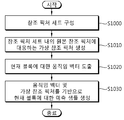
- FIG. 10 schematically illustrates an example of an inter prediction method according to the present invention.
- the method disclosed in FIG. 10 may be performed by a decoding apparatus.
- the decoding apparatus configures a reference picture set for a current picture (S1000).
- the reference picture set may include reconstructed (or decoded) pictures preceding the current picture in decoding order as original reference pictures.
- the decoding apparatus generates a virtual reference picture corresponding to the original reference picture in the reference picture (S1010).
- the decoding apparatus may implicitly generate the virtual reference picture through the same reference as the encoding apparatus, or may obtain VRP information from the bitstream and generate the most reference picture based on the VRP information.
- the virtual reference picture may be generated based on a homography transform on the original reference picture.
- the homography transformation is performed based on a homography matrix, and the homography matrix may be derived based on the positional relationship between four corner pixels of the current picture and corresponding pixels of the original reference picture.
- the VRP information may include location information of the corresponding pixels.
- the VRP information may include coefficients of the homography matrix.
- the virtual reference picture may be generated based on illumination compensation of the original reference picture.
- the VRP information may include a weight value and an offset value for the illumination compensation.
- the decoding apparatus may parse and acquire a VRP_use_flag syntax element from the bitstream.
- the decoding apparatus may generate the virtual reference picture when the value of the VRP_use_flag syntax element is 1.
- the decoding apparatus may parse and acquire, from the bitstream, a VRP_pos_in_rps syntax element indicating the position of the virtual reference picture within the reference picture set.
- the VRP_pos_in_rps syntax element may be parsed and obtained only when the value of the VRP_use_flag syntax element is 1.
- the decoding apparatus derives a motion vector for the current block in the current picture (S1020).
- the decoding apparatus may use the motion vector of one of the merge candidate lists as the motion vector of the current block (in the case of merge mode), or use the motion vector of the motion vector predictor candidate list as the motion vector predictor.
- the MVD obtained from the bitstream may be added to a vector predictor to derive a motion vector of the current block (in case of AMVP mode).
- Information about the inter prediction mode may be obtained through the bitstream.
- the decoding apparatus may construct a reference picture list including the virtual reference picture.
- the decoding apparatus may derive a reference picture index for the current block.
- the reference picture index may be derived based on the reference picture index of the merge candidate selected from the merge candidate list (in case of merge mode), or may parse and obtain a syntax element regarding the reference picture index from the bitstream.
- the reference picture list may include a plurality of original reference pictures and the virtual reference picture.
- the index of the virtual reference picture may have a lower value than the indexes of the original reference pictures.
- the reference picture index indicating the virtual reference picture may indicate 0.
- the index of the virtual reference picture may have a higher value than the indexes of the original reference pictures based on an RD cost.
- the decoding apparatus may parse and acquire a pu_VRP_use_flag syntax element from the bitstream.
- the reference picture list may include the original reference picture and the virtual reference picture.
- the reference picture index indicates the virtual reference picture and the value of the pu_VRP_use_flag syntax element. If 0, the reference picture index may indicate the original reference picture.
- the decoding apparatus generates a prediction sample (or a prediction sample array) for the current block based on the derived motion vector of the current block and the virtual reference picture (S1030).
- the decoding apparatus may derive a reference block indicated by the motion vector on the virtual reference picture, and use a reconstructed sample in the reference block as a prediction sample for the current block.
- the decoding device may receive information about the residual sample for the current block from the bitstream.
- the information about the residual sample may include transform coefficients regarding the residual sample.
- the decoding apparatus may derive the residual sample (or residual sample array) for the current block based on the information about the residual sample.
- the decoding apparatus may generate a reconstructed sample based on the prediction sample and the residual sample, and may derive a reconstructed block or a reconstructed picture based on the reconstructed sample. Thereafter, as described above, the decoding apparatus may apply an in-loop filtering procedure, such as a deblocking filtering and / or SAO procedure, to the reconstructed picture in order to improve subjective / objective picture quality as necessary.
- an in-loop filtering procedure such as a deblocking filtering and / or SAO procedure
- the performance of inter prediction can be improved based on a virtual reference picture that is more correlated with the current picture, thereby reducing the amount of data allocated to the residual signal and improving the overall coding efficiency. have.
- the above-described method may be implemented as a module (process, function, etc.) for performing the above-described function.
- the module may be stored in memory and executed by a processor.
- the memory may be internal or external to the processor and may be coupled to the processor by various well known means.
- the processor may include application-specific integrated circuits (ASICs), other chipsets, logic circuits, and / or data processing devices.
- the memory may include read-only memory (ROM), random access memory (RAM), flash memory, memory card, storage medium and / or other storage device.
Abstract
본 발명에 따른 디코딩 장치에 의하여 수행되는 인터 예측 방법은 현재 픽처에 대한 참조 픽처 세트를 구성하는 단계, 상기 참조 픽처 세트 내의 원본 참조 픽처에 대응하는 가상 참조 픽처를 생성하는 단계, 상기 현재 픽처 내의 현재 블록에 대한 움직임 벡터를 도출하는 단계, 및 상기 움직임 벡터 및 상기 가상 참조 픽처를 기반으로 상기 현재 블록에 대한 예측 샘플을 생성하는 단계를 포함함을 특징으로 한다. 본 발명에 따르면, 현재 픽처와 보다 상관관계가 높은 가상 참조 픽처를 기반으로 인터 예측의 성능을 높일 수 있으며, 이를 통하여 레지듀얼 신호에 할당되는 데이터량을 줄이고, 전반적인 코딩 효율을 향상시킬 수 있다.
Description
본 발명은 비디오 코딩 기술에 관한 것으로서 보다 상세하게는 비디오 코딩 시스템에서 가상 참조 픽처 기반 인터 예측 방법 및 장치에 관한 것이다.
최근 HD(High Definition) 영상 및 UHD(Ultra High Definition) 영상과 같은 고해상도, 고품질의 영상에 대한 수요가 다양한 분야에서 증가하고 있다. 영상 데이터가 고해상도, 고품질이 될수록 기존의 영상 데이터에 비해 상대적으로 전송되는 정보량 또는 비트량이 증가하기 때문에 기존의 유무선 광대역 회선과 같은 매체를 이용하여 영상 데이터를 전송하거나 기존의 저장 매체를 이용해 영상 데이터를 저장하는 경우, 전송 비용과 저장 비용이 증가된다.
이에 따라, 고해상도, 고품질 영상의 정보를 효과적으로 전송하거나 저장하고, 재생하기 위해 고효율의 영상 압축 기술이 요구된다.
본 발명의 기술적 과제는 비디오 코딩 효율을 높이는 방법 및 장치를 제공함에 있다.
본 발명의 다른 기술적 과제는 인터 예측 성능을 높이는 방법 및 장치를 제공함에 있다.
본 발명의 또 다른 기술적 과제는 가상 참조 픽처를 생성하는 방법 및 장치를 제공함에 있다.
본 발명의 또 다른 기술적 과제는 가상 참조 픽처를 활용하여 예측 신호의 정확도를 높임에 있다.
본 발명의 또 다른 기술적 과제는 호모그래피(homography) 정보를 이용하여 가상 참조 픽처를 생성하는 방법 및 장치를 제공함에 있다.
본 발명의 또 다른 기술적 과제는 필터링을 통하여 가상 참조 픽처를 생성하는 방법 및 장치를 제공함에 있다.
본 발명의 또 다른 기술적 과제는 가상 참조 픽처를 관리하는 방법 및 장치를 제공함에 있다.
본 발명의 일 실시예에 따르면, 디코딩 장치에 의하여 수행되는 인터 예측 방법을 제공한다. 상기 인터 예측 방법은 현재 픽처에 대한 참조 픽처 세트(reference picture set)를 구성하는 단계, 상기 참조 픽처 세트 내의 원본 참조 픽처(original reference picture)에 대응하는 가상 참조 픽처(virtual reference picture)를 생성하는 단계, 상기 현재 픽처 내의 현재 블록에 대한 움직임 벡터를 도출하는 단계, 및 상기 움직임 벡터 및 상기 가상 참조 픽처를 기반으로 상기 현재 블록에 대한 예측 샘플을 생성하는 단계를 포함함을 특징으로 한다.
본 발명의 다른 일 실시예에 따르면, 인터 예측을 수행하는 디코딩 장치를 제공한다. 상기 디코딩 장치는 비트스트림으로부터 현재 블록에 대한 인터 예측 모드에 관한 정보를 획득하는 디코딩부, 현재 픽처에 대한 참조 픽처 세트(reference picture set)를 구성하고, 상기 참조 픽처 세트 내의 원본 참조 픽처(original reference picture)에 대응하는 가상 참조 픽처(virtual reference picture)를 생성하고, 상기 현재 픽처 내의 상기 현재 블록에 대한 움직임 벡터를 도출하고, 및 상기 움직임 벡터 및 상기 가상 참조 픽처를 기반으로 상기 현재 블록에 대한 예측 샘플을 생성하는 예측부를 포함함을 특징으로 한다.
본 발명의 또 다른 일 실시예에 따르면, 인코딩 장치에 의하여 수행되는 영상 인코딩 방법이 제공된다. 상기 영상 인코딩 방법은 현재 픽처에 대한 참조 픽처 세트(reference picture set)를 구성하는 단계, 상기 참조 픽처 세트 내의 원본 참조 픽처(original reference picture)에 대응하는 가상 참조 픽처(virtual reference picture)를 생성하는 단계, 상기 가상 참조 픽처를 기반으로 상기 현재 픽처 내의 현재 블록에 대한 움직임 벡터 및 예측 샘플을 도출하는 단계, 상기 현재 블록에 대한 원본 샘플 및 상기 예측 샘플을 기반으로 레지듀얼 샘플을 도출하는 단계, 및 상기 움직임 벡터에 관한 정보 및 상기 레지듀얼 샘플에 관한 정보를 인코딩하여 출력하는 단계를 포함함을 특징으로 한다.
본 발명의 또 다른 일 실시예에 따르면, 영상 인코딩을 수행하는 인코딩 장치가 제공된다. 상기 인코딩 장치는 현재 픽처에 대한 참조 픽처 세트(reference picture set)를 구성하는 단계, 상기 참조 픽처 세트 내의 원본 참조 픽처(original reference picture)에 대응하는 가상 참조 픽처(virtual reference picture)를 생성하고, 상기 가상 참조 픽처를 기반으로 상기 현재 픽처 내의 현재 블록에 대한 움직임 벡터 및 예측 샘플을 도출하고, 상기 현재 블록에 대한 원본 샘플 및 상기 예측 샘플을 기반으로 레지듀얼 샘플을 도출하는 예측부, 및 상기 움직임 벡터에 관한 정보 및 상기 레지듀얼 샘플에 관한 정보를 인코딩하여 출력하는 인코딩부를 포함함을 특징으로 한다.
본 발명에 따르면, 현재 픽처와 보다 상관관계가 높은 가상 참조 픽처를 기반으로 인터 예측의 성능을 높일 수 있으며, 이를 통하여 레지듀얼 신호에 할당되는 데이터량을 줄이고, 전반적인 코딩 효율을 향상시킬 수 있다.
도 1은 본 발명의 일 실시예에 따른 비디오 인코딩 장치를 개략적으로 도시한 블록도이다.
도 2는 본 발명의 일 실시예에 따른 비디오 디코딩 장치를 개략적으로 도시한 블록도이다.
도 3은 인터 예측을 위한 DPB 및 참조 픽처들을 예시적으로 나타낸다.
도 4는 가상 참조 픽처에 대한 개념을 예시적으로 나타낸다.
도 5는 가상 참조 픽처를 고려하는 디코딩 절차를 나타낸다.
도 6은 호모그래피 메트릭스에 따른 현재 픽처와 원본 참조 픽처 간 매핑관계를 나타낸다.
도 7은 본 발명에 따른 가상 참조 픽처 생성 절차의 일 예를 나타낸다.
도 8은 참조 픽처 세트 또는 참조 픽처 리스트 구성을 예시적으로 나타낸다.
도 9는 본 발명에 따른 영상 코딩 방법의 일 예를 개략적으로 나타낸다.
도 10은 본 발명에 따른 인터 예측 방법의 일 예를 개략적으로 나타낸다.
본 발명은 다양한 변경을 가할 수 있고 여러 가지 실시예를 가질 수 있는 바, 특정 실시예들을 도면에 예시하고 상세하게 설명하고자 한다. 그러나, 이는 본 발명을 특정한 실시 형태에 대해 한정하려는 것이 아니다. 본 명세서에서 사용하는 용어는 단지 특정한 실시예를 설명하기 위해 사용된 것으로, 본 발명의 기술적 사상을 한정하려는 의도로 사용되는 것은 아니다. 단수의 표현은 문맥상 명백하게 다르게 뜻하지 않는 한, 복수의 표현을 포함한다. 본 명세서에서, "포함하다" 또는 "가지다" 등의 용어는 명세서상에 기재된 특징, 숫자, 단계, 동작, 구성 요소, 부품 또는 이들을 조합한 것이 존재함을 지정하려는 것이지, 하나 또는 그 이상의 다른 특징들이나 숫자, 단계, 동작, 구성 요소, 부품 또는 이들을 조합한 것들의 존재 또는 부가 가능성을 미리 배제하지 않는 것으로 이해되어야 한다.
한편, 본 발명에서 설명되는 도면상의 각 구성들은 비디오 인코딩 장치/디코딩 장치에서 서로 다른 특징적인 기능들에 관한 설명의 편의를 위해 독립적으로 도시된 것으로서, 각 구성들이 서로 별개의 하드웨어나 별개의 소프트웨어로 구현된다는 것을 의미하지는 않는다. 예컨대, 각 구성 중 두 개 이상의 구성이 합쳐져 하나의 구성을 이룰 수도 있고, 하나의 구성이 복수의 구성으로 나뉘어질 수도 있다. 각 구성이 통합 및/또는 분리된 실시예도 본 발명의 본질에서 벗어나지 않는 한 본 발명에 포함된다.
이하, 첨부한 도면들을 참조하여, 본 발명의 실시예를 보다 상세하게 설명하고자 한다.
도 1은 본 발명의 일 실시예에 따른 비디오 인코딩 장치를 개략적으로 도시한 블록도이다.
도 1을 참조하면, 인코딩 장치(100)는 픽처 분할부(105), 예측부(110), 변환부(115), 양자화부(120), 재정렬부(125), 엔트로피 인코딩부(130), 역양자화부(135), 역변환부(140), 필터부(145) 및 메모리(150)를 구비한다.
픽처 분할부(105)는 입력된 픽처를 적어도 하나의 처리 단위 블록으로 분할할 수 있다. 이때, 처리 단위로서의 블록은 예측 유닛(Prediction Unit, PU)일 수도 있고, 변환 유닛(Transform Unit, TU)일 수도 있으며, 코딩 유닛(Coding Unit, CU)일 수도 있다. 픽처는 복수의 코딩 트리 유닛(Coding Tree Unit, CTU)들로 구성될 수 있으며, 각각의 CTU는 쿼드 트리(quad-tree) 구조로 CU들로 분할(split)될 수 있다. CU는 보다 하위(deeper) 뎁스의 CU들로 쿼드 트리 구조로 분할될 수도 있다. PU 및 TU는 CU로부터 획득될 수 있다. 예를 들어, PU는 CU로부터 대칭 또는 비대칭 사각형 구조로 파티셔닝(partitioning)될 수 있다. 또한 TU는 CU로부터 쿼드 트리 구조로 분할될 수도 있다. CTU는 CTB(coding tree block)에 대응될 수 있고, CU는 CB(coding block)에 대응될 수 있고, PU는 PB(prediction block)에 대응될 수 있고, TU는 TB(transform block)에 대응될 수 있다.
예측부(110)는 후술하는 바와 같이, 인터 예측을 수행하는 인터 예측부와 인트라 예측을 수행하는 인트라 예측부를 포함한다. 예측부(110)는, 픽처 분할부(105)에서 픽처의 처리 단위에 대하여 예측을 수행하여 예측 샘플(또는 예측 샘플 어레이)을 포함하는 예측 블록을 생성한다. 예측부(110)에서 픽처의 처리 단위는 CU일 수도 있고, TU일 수도 있고, PU일 수도 있다. 또한, 예측부(110)는 해당 처리 단위에 대하여 실시되는 예측이 인터 예측인지 인트라 예측인지를 결정하고, 각 예측 방법의 구체적인 내용(예컨대, 예측 모드 등)을 정할 수 있다. 이때, 예측이 수행되는 처리 단위와 예측 방법 및 예측 방법의 구체적인 내용이 정해지는 처리 단위는 다를 수 있다. 예컨대, 예측의 방법과 예측 모드 등은 PU 단위로 결정되고, 예측의 수행은 TU 단위로 수행될 수도 있다.
인터 예측을 통해서는 현재 픽처의 이전 픽처 및/또는 이후 픽처 중 적어도 하나의 픽처의 정보를 기초로 예측을 수행하여 예측 블록을 생성할 수 있다. 또한, 인트라 예측을 통해서는 현재 픽처 내의 픽셀 정보를 기초로 예측을 수행하여 예측 블록을 생성할 수 있다.
인터 예측의 방법으로서, 스킵(skip) 모드, 머지(merge) 모드, AMVP(Advanced Motion Vector Prediction) 등을 이용할 수 있다. 인터 예측에서는 PU에 대하여, 참조 픽처를 선택하고 PU에 대응하는 참조 블록을 선택할 수 있다. 참조 블록은 정수 픽셀(또는 샘플) 또는 분수 픽셀(또는 샘플) 단위로 선택될 수 있다. 이어서, PU와의 레지듀얼(residual) 신호가 최소화되며 움직임 벡터 크기 역시 최소가 되는 예측 블록이 생성된다. 본 명세서에서 픽셀(pixel), 펠(pel) 및 샘플(sample)은 서로 혼용될 수 있다.
예측 블록은 정수 픽셀 단위로 생성될 수도 있고, 1/2 픽셀 단위 또는 1/4 픽셀 단위와 같이 정수 이하 픽셀 단위로 생성될 수도 있다. 이때, 움직임 벡터 역시 정수 픽셀 이하의 단위로 표현될 수 있다.
인터 예측을 통해 선택된 참조 픽처의 인덱스, 움직임 벡터 차분(motion vector difference, MVD), 움직임 벡터 예측자(motion vector predictor, MVP), 레지듀얼 신호 등의 정보는 엔트로피 인코딩되어 디코딩 장치에 전달될 수 있다. 스킵 모드가 적용되는 경우에는 예측 블록을 복원 블록으로 할 수 있으므로, 레지듀얼을 생성, 변환, 양자화, 전송하지 않을 수 있다.
인트라 예측을 수행하는 경우에는, PU 단위로 예측 모드가 정해져서 PU 단위로 예측이 수행될 수 있다. 또한, PU 단위로 예측 모드가 정해지고 TU 단위로 인트라 예측이 수행될 수도 있다.
인트라 예측에서 예측 모드는 예를 들어 33개의 방향성 예측 모드와 적어도 2개 이상의 비방향성 모드를 가질 수 있다. 비방향성 모드는 DC 예측 모드 및 플래너 모드(Planar 모드)을 포함할 수 있다.
인트라 예측에서는 참조 샘플에 필터를 적용한 후 예측 블록을 생성할 수 있다. 이때, 참조 샘플에 필터를 적용할 것인지는 현재 블록의 인트라 예측 모드 및/또는 사이즈에 따라 결정될 수 있다.
생성된 예측 블록과 원본 블록 사이의 레지듀얼 값(레지듀얼 블록 또는 레지듀얼 신호)은 변환부(115)로 입력된다. 또한, 예측을 위해 사용한 예측 모드 정보, 움직임 벡터 정보 등은 레지듀얼 값과 함께 엔트로피 인코딩부(130)에서 인코딩되어 디코딩 장치에 전달된다.
변환부(115)는 변환 블록 단위로 레지듀얼 블록에 대한 변환을 수행하고 변환 계수를 생성한다.
변환 블록은 샘플들의 직사각형 블록으로서 동일한 변환이 적용되는 블록이다. 변환 블록은 변환 유닛(TU)일 수 있으며, 쿼드 트리(quad tree) 구조를 가질 수 있다.
변환부(115)는 레지듀얼 블록에 적용된 예측 모드와 블록의 크기에 따라서 변환을 수행할 수 있다.
예컨대, 레지듀얼 블록에 인트라 예측이 적용되었고 블록이 4x4의 레지듀얼 배열(array)이라면, 레지듀얼 블록을 DST(Discrete Sine Transform)를 이용하여 변환하고, 그 외의 경우라면 레지듀얼 블록을 DCT(Discrete Cosine Transform)를 이용하여 변환할 수 있다.
변환부(115)는 변환에 의해 변환 계수들의 변환 블록을 생성할 수 있다.
양자화부(120)는 변환부(115)에서 변환된 레지듀얼 값들, 즉 변환 계수들을 양자화하여 양자화된 변환 계수를 생성할 수 있다. 양자화부(120)에서 산출된 값은 역양자화부(135)와 재정렬부(125)에 제공된다.
재정렬부(125)는 양자화부(120)로부터 제공된 양자화된 변환 계수를 재정렬한다. 양자화된 변환 계수를 재정렬함으로써 엔트로피 인코딩부(130)에서의 인코딩 효율을 높일 수 있다.
재정렬부(125)는 계수 스캐닝(Coefficient Scanning) 방법을 통해 2차원 블록 형태의 양자화된 변환 계수들을 1차원의 벡터 형태로 재정렬할 수 있다.
엔트로피 인코딩부(130)는 재정렬부(125)에 의해 재정렬된 양자화된 변환 값들 또는 코딩 과정에서 산출된 인코딩 파라미터 값 등을 기초로 심볼(symbol)을 확률 분포에 따라 엔트로피 코딩하여 비트스트림(bitstream)을 출력할 수 있다. 엔트로피 인코딩 방법은 다양한 값을 갖는 심볼을 입력 받아, 통계적 중복성을 제거하면서, 디코딩 가능한 2진수의 열로 표현하는 방법이다.
여기서, 심볼이란 인코딩/디코딩 대상 구문 요소(syntax element) 및 코딩 파라미터(coding parameter), 레지듀얼 신호(residual signal)의 값 등을 의미한다. 인코딩 파라미터는 인코딩 및 디코딩에 필요한 매개변수로서, 구문 요소와 같이 인코딩 장치에서 인코딩되어 디코딩 장치로 전달되는 정보뿐만 아니라, 인코딩 혹은 디코딩 과정에서 유추될 수 있는 정보를 포함할 수 있으며 영상을 인코딩하거나 디코딩할 때 필요한 정보를 의미한다. 인코딩 파라미터는 예를 들어 인트라/인터 예측모드, 이동/움직임 벡터, 참조 영상 색인, 코딩 블록 패턴, 잔여 신호 유무, 변환 계수, 양자화된 변환 계수, 양자화 파라미터, 블록 크기, 블록 분할 정보 등의 값 또는 통계를 포함할 수 있다. 또한 잔여 신호는 원신호와 예측 신호의 차이를 의미할 수 있고, 또한 원신호와 예측 신호의 차이가 변환(transform)된 형태의 신호 또는 원신호와 예측 신호의 차이가 변환되고 양자화된 형태의 신호를 의미할 수도 있다. 잔여 신호는 블록 단위에서는 잔여 블록이라 할 수 있고, 샘플 단위에서는 잔여 샘플이라고 할 수 있다.
엔트로피 인코딩이 적용되는 경우, 높은 발생 확률을 갖는 심볼에 적은 수의 비트가 할당되고 낮은 발생 확률을 갖는 심볼에 많은 수의 비트가 할당되어 심볼이 표현됨으로써, 인코딩 대상 심볼들에 대한 비트열의 크기가 감소될 수 있다. 따라서 엔트로피 인코딩을 통해서 영상 인코딩의 압축 성능이 높아질 수 있다.
엔트로피 인코딩을 위해 지수 골룸(exponential golomb), CAVLC(Context-Adaptive Variable Length Coding), CABAC(Context-Adaptive Binary Arithmetic Coding)과 같은 인코딩 방법이 사용될 수 있다. 예를 들어, 엔트로피 인코딩부(130)에는 가변 길이 코딩(VLC: Variable Length Coding/Code) 테이블과 같은 엔트로피 인코딩을 수행하기 위한 테이블이 저장될 수 있고, 엔트로피 인코딩부(130)는 저장된 가변 길이 코딩(VLC) 테이블을 사용하여 엔트로피 인코딩을 수행할 수 있다. 또한 엔트로피 인코딩부(130)는 대상 심볼의 이진화(binarization) 방법 및 대상 심볼/빈(bin)의 확률 모델(probability model)을 도출(derive)한 후, 도출된 이진화 방법 또는 확률 모델을 사용하여 엔트로피 인코딩을 수행할 수도 있다.
또한, 엔트로피 인코딩부(130)는 필요한 경우에, 전송하는 파라미터 셋(parameter set) 또는 신택스에 일정한 변경을 가할 수도 있다.
역양자화부(135)는 양자화부(120)에서 양자화된 값(양자화된 변환 계수)들을 역양자화하고, 역변환부(140)는 역양자화부(135)에서 역양자화된 값들을 역변환한다.
역양자화부(135) 및 역변환부(140)에서 생성된 레지듀얼 값(또는 레지듀얼 샘플 또는 레지듀얼 샘플 어레이)과 예측부(110)에서 예측된 예측 블록이 합쳐져 복원 샘플(또는 복원 샘플 어레이)를 포함하는 복원 블록(Reconstructed Block)이 생성될 수 있다.
도 1에서는 가산기를 통해서, 레지듀얼 블록과 예측 블록이 합쳐져 복원 블록이 생성되는 것으로 설명하고 있다. 이때, 가산기를 복원 블록을 생성하는 별도의 유닛(복원 블록 생성부)로 볼 수도 있다.
필터부(145)는 디블록킹 필터, ALF(Adaptive Loop Filter), SAO(Sample Adaptive Offset)를 복원된 픽처에 적용할 수 있다.
디블록킹 필터는 복원된 픽처에서 블록 간의 경계에 생긴 왜곡을 제거할 수 있다. ALF(Adaptive Loop Filter)는 디블록킹 필터를 통해 블록이 필터링된 후 복원된 영상과 원래의 영상을 비교한 값을 기초로 필터링을 수행할 수 있다. ALF는 고효율을 적용하는 경우에만 수행될 수도 있다. SAO는 디블록킹 필터가 적용된 레지듀얼 블록에 대하여, 픽셀 단위로 원본 영상과의 오프셋 차이를 복원하며, 밴드 오프셋(Band Offset), 엣지 오프셋(Edge Offset) 등의 형태로 적용된다.
한편, 인터 예측에 사용되는 복원 블록에 대해서 필터부(145)는 필터링을 적용하지 않을 수도 있다.
메모리(150)는 필터부(145)를 통해 산출된 복원 블록 또는 픽처를 저장할 수 있다. 메모리(150)에 저장된 복원 블록 또는 픽처는 인터 예측을 수행하는 예측부(110)에 제공될 수 있다.
도 2는 본 발명의 일 실시예에 따른 비디오 디코딩 장치를 개략적으로 나타낸 블록도이다. 도 2를 참조하면, 비디오 디코딩 장치(200)는 엔트로피 디코딩부(210), 재정렬부(215), 역양자화부(220), 역변환부(225), 예측부(230), 필터부(235) 메모리(240)를 포함할 수 있다.
비디오 인코딩 장치에서 영상 비트스트림이 입력된 경우, 입력된 비트스트림은 비디오 인코딩 장치에서 영상 정보가 처리된 절차에 따라서 디코딩될 수 있다.
엔트로피 디코딩부(210)는, 입력된 비트스트림을 확률 분포에 따라 엔트로피 디코딩하여, 양자화된 계수(quantized coefficient) 형태의 심볼을 포함한 심볼들을 생성할 수 있다. 엔트로피 디코딩 방법은 2진수의 열을 입력 받아 각 심볼들을 생성하는 방법이다. 엔트로피 디코딩 방법은 상술한 엔트로피 인코딩 방법과 유사하다.
예컨대, 비디오 인코딩 장치에서 엔트로피 인코딩을 수행하기 위해 CAVLC 등의 가변 길이 코딩(Variable Length Coding: VLC, 이하 'VLC' 라 함)가 사용된 경우에, 엔트로피 디코딩부(210)도 인코딩 장치에서 사용한 VLC 테이블과 동일한 VLC 테이블로 구현하여 엔트로피 디코딩을 수행할 수 있다. 또한, 비디오 인코딩 장치에서 엔트로피 인코딩을 수행하기 위해 CABAC을 이용한 경우에, 엔트로피 디코딩부(210)는 이에 대응하여 CABAC을 이용한 엔트로피 디코딩을 수행할 수 있다.
보다 상세하게, CABAC 엔트로피 디코딩 방법은, 비트스트림에서 각 구문 요소에 해당하는 빈을 수신하고, 디코딩 대상 구문 요소 정보와 주변 및 디코딩 대상 블록의 디코딩 정보 혹은 이전 단계에서 디코딩된 심볼/빈의 정보를 이용하여 문맥(context) 모델을 결정하고, 결정된 문맥 모델에 따라 빈(bin)의 발생 확률을 예측하여 빈의 산술 디코딩(arithmetic decoding)를 수행하여 각 구문 요소의 값에 해당하는 심볼을 생성할 수 있다. 이때, CABAC 엔트로피 디코딩 방법은 문맥 모델 결정 후 다음 심볼/빈의 문맥 모델을 위해 디코딩된 심볼/빈의 정보를 이용하여 문맥 모델을 업데이트할 수 있다.
엔트로피 디코딩부(210)에서 디코딩된 정보 중 예측 블록을 생성하기 위한 정보는 예측부(230)로 제공되고, 엔트로피 디코딩부(210)에서 엔트로피 디코딩이 수행된 레지듀얼 값, 즉 양자화된 변환 계수는 재정렬부(215)로 입력될 수 있다.
재정렬부(215)는 엔트로피 디코딩부(210)에서 엔트로피 디코딩된 비트스트림의 정보, 즉 양자화된 변환 계수를 인코딩 장치에서 재정렬한 방법을 기초로 재정렬할 수 있다.
재정렬부(215)는 1차원 벡터 형태로 표현된 계수들을 다시 2차원의 블록 형태의 계수로 복원하여 재정렬할 수 있다. 재정렬부(215)는 현재 블록(변환 블록)에 적용된 예측 모드와 변환 블록의 크기를 기반으로 계수에 대한 스캐닝을 수행하여 2 차원 블록 형태의 계수(양자화된 변환 계수) 배열(array)을 생성할 수 있다.
역양자화부(220)는 인코딩 장치에서 제공된 양자화 파라미터와 재정렬된 블록의 계수값을 기초로 역양자화를 수행할 수 있다.
역변환부(225)는 비디오 인코딩 장치에서 수행된 양자화 결과에 대해, 인코딩 장치의 변환부가 수행한 DCT 및 DST에 대해 역DCT 및/또는 역DST를 수행할 수 있다.
역변환은 인코딩 장치에서 결정된 전송 단위 또는 영상의 분할 단위를 기초로 수행될 수 있다. 인코딩 장치의 변환부에서 DCT 및/또는 DST는 예측 방법, 현재 블록의 크기 및 예측 방향 등 복수의 정보에 따라 선택적으로 수행될 수 있고, 디코딩 장치의 역변환부(225)는 인코딩 장치의 변환부에서 수행된 변환 정보를 기초로 역변환을 수행할 수 있다.
예측부(230)는 엔트로피 디코딩부(210)에서 제공된 예측 블록 생성 관련 정보와 메모리(240)에서 제공된 이전에 디코딩된 블록 및/또는 픽처 정보를 기초로 예측 샘플(또는 예측 샘플 어레이)를 포함하는 예측 블록을 생성할 수 있다.
현재 PU에 대한 예측 모드가 인트라 예측(intra prediction) 모드인 경우에, 현재 픽처 내의 픽셀 정보를 기초로 예측 블록을 생성하는 인트라 예측을 수행할 수 있다.
현재 PU에 대한 예측 모드가 인터 예측(inter prediction) 모드인 경우에, 현재 픽처의 이전 픽처 또는 이후 픽처 중 적어도 하나의 픽처에 포함된 정보를 기초로 현재 PU에 대한 인터 예측을 수행할 수 있다. 이때, 비디오 인코딩 장치에서 제공된 현재 PU의 인터 예측에 필요한 움직임 정보, 예컨대 움직임 벡터, 참조 픽처 인덱스 등에 관한 정보는 인코딩 장치로부터 수신한 스킵 플래그, 머지 플래그 등을 확인하고 이에 대응하여 유도될 수 있다.
현재 픽처에 대한 인터 예측 시, 현재 블록과의 레지듀얼(residual) 신호가 최소화되며 움직임 벡터 크기 역시 최소가 되도록 예측 블록을 생성할 수 있다.
한편, 움직임 정보 도출 방식은 현재 블록의 예측 모드에 따라 달라질 수 있다. 인터 예측을 위해 적용되는 예측 모드에는 AMVP(Advanced Motion Vector Prediction) 모드, 머지(merge) 모드 등이 있을 수 있다.
일 예로, 머지 모드가 적용되는 경우, 인코딩 장치 및 디코딩 장치는 복원된 공간적 주변 블록의 움직임 벡터 및/또는 시간적 주변 블록인 Col 블록에 대응하는 움직임 벡터를 이용하여, 머지 후보 리스트를 생성할 수 있다. 머지 모드에서는 머지 후보 리스트에서 선택된 후보 블록의 움직임 벡터가 현재 블록의 움직임 벡터로 사용된다. 인코딩 장치는 상기 머지 후보 리스트에 포함된 후보 블록들 중에서 선택된 최적의 움직임 벡터를 갖는 후보 블록을 지시하는 머지 인덱스를 디코딩 장치로 전송할 수 있다. 이 때, 디코딩 장치는 상기 머지 인덱스를 이용하여, 현재 블록의 움직임 벡터를 도출할 수 있다.
다른 예로, AMVP(Advanced Motion Vector Prediction) 모드가 적용되는 경우, 인코딩 장치 및 디코딩 장치는 복원된 공간적 주변 블록의 움직임 벡터 및/또는 시간적 주변 블록인 Col 블록에 대응하는 움직임 벡터를 이용하여, 움직임 벡터 예측자 후보 리스트를 생성할 수 있다. 즉, 복원된 공간적 주변 블록의 움직임 벡터 및/또는 시간적 주변 블록인 Col 블록에 대응하는 움직임 벡터는 움직임 벡터 후보로 사용될 수 있다. 인코딩 장치는 상기 리스트에 포함된 움직임 벡터 후보 중에서 선택된 최적의 움직임 벡터를 지시하는 예측 움직임 벡터 인덱스를 디코딩 장치로 전송할 수 있다. 이 때, 디코딩 장치는 상기 움직임 벡터 인덱스를 이용하여, 움직임 벡터 후보 리스트에 포함된 움직임 벡터 후보 중에서, 현재 블록의 예측 움직임 벡터를 선택할 수 있다.
인코딩 장치는 현재 블록의 움직임 벡터(MV)와 움직임 벡터 예측자(MVP) 간의 움직임 벡터 차분(MVD)을 구할 수 있고, 이를 인코딩하여 디코딩 장치로 전송할 수 있다. 즉, MVD는 현재 블록의 MV에서 MVP를 뺀 값으로 구해질 수 있다. 이 때, 디코딩 장치는 수신된 움직임 벡터 차분을 디코딩할 수 있고, 디코딩된 움직임 벡터 차분과 움직임 벡터 예측자의 가산을 통해 현재 블록의 움직임 벡터를 도출할 수 있다.
인코딩 장치는 또한 참조 픽처를 지시하는 참조 픽처 인덱스 등을 디코딩 장치에 전송할 수 있다.
디코딩 장치는 주변 블록의 움직임 정보들을 이용하여 현재 블록의 움직임 벡터를 예측하고, 인코딩 장치로부터 수신한 레지듀얼을 이용하여 현재 블록에 대한 움직임 벡터를 유도할 수 있다. 디코딩 장치는 유도한 움직임 벡터와 인코딩 장치로부터 수신한 참조 픽처 인덱스 정보를 기반으로 현재 블록에 대한 예측 샘플(또는 예측 샘플 어레이)을 생성할 수 있다.
디코딩 장치는 예측 샘플(또는 예측 샘플 어레이)과 인코딩 장치로부터 전송되는 변환 계수들로부터 획득한 레지듀얼 샘플(레지듀얼 샘플 어레이)을 더하여 복원 샘플(또는 복원 샘플 어레이)를 생성할 수 있다. 이를 기반으로 복원 블록 및 복원 픽처가 생성될 수 있다.
상술한 AMVP 및 머지 모드에서는, 현재 블록의 움직임 정보를 도출하기 위해, 복원된 주변 블록의 움직임 정보 및/또는 콜 블록의 움직임 정보가 사용될 수 있다.
인터 예측에 이용되는 다른 모드 중 하나인 스킵 모드의 경우에, 주변 블록의 정보를 그대로 현재 블록에 이용할 수 있다. 따라서 스킵 모드의 경우에, 인코딩 장치는 현재 블록의 움직임 정보로서 어떤 블록의 움직임 정보를 이용할 것인지를 지시하는 정보 외에 레지듀얼 등과 같은 신택스 정보를 디코딩 장치에 전송하지 않는다.
복원 블록은 예측부(230)에서 생성된 예측 블록과 역변환부(225)에서 제공된 레지듀얼 블록을 이용해 생성될 수 있다. 도 2에서는 가산기에서 예측 블록과 레지듀얼 블록이 합쳐져 복원 블록이 생성되는 것으로 설명하고 있다. 이때, 가산기를 복원 블록을 생성하는 별도의 유닛(복원 블록 생성부)로 볼 수 있다. 여기서 상기 복원 블록은 상술한 바와 같이 복원 샘플(또는 복원 샘플 어레이)를 포함하고, 상기 예측 블록은 예측 샘플(또는 예측 샘플 어레이)를 포함하고, 상기 레지듀얼 블록은 레지듀얼 샘플(또는 레지듀얼 샘플 어레이)를 포함할 수 있다. 따라서, 복원 샘플(또는 복원 샘플 어레이)은 대응하는 예측 샘플(또는 예측 샘플 어레이)과 레지듀얼 샘플(레지듀얼 샘플 어레이)이 합쳐서 생성된다고 표현될 수도 있다.
스킵 모드가 적용되는 블록에 대하여는 레지듀얼이 전송되지 않으며 예측 블록을 복원 블록으로 할 수 있다.
복원된 블록 및/또는 픽처는 필터부(235)로 제공될 수 있다. 필터부(235)는 복원된 블록 및/또는 픽처에 디블록킹 필터링, SAO(Sample Adaptive Offset) 및/또는 ALF 등을 적용할 수 있다.
메모리(240)는 복원된 픽처 또는 블록을 저장하여 참조 픽처 또는 참조 블록으로 사용할 수 있도록 할 수 있고 또한 복원된 픽처를 출력부로 제공할 수 있다.
디코딩 장치(200)에 포함되어 있는 엔트로피 디코딩부(210), 재정렬부(215), 역양자화부(220), 역변환부(225), 예측부(230), 필터부(235) 및 메모리(240) 중 영상의 디코딩에 직접적으로 관련된 구성요소들, 예컨대, 엔트로피 디코딩부(210), 재정렬부(215), 역양자화부(220), 역변환부(225), 예측부(230), 필터부(235) 등을 다른 구성요소와 구분하여 디코더 또는 디코딩부로 표현할 수 있다.
또한, 디코딩 장치(200)는 비트스트림에 포함되어 있는 인코딩된 영상에 관련된 정보를 파싱(parsing)하는 도시되지 않은 파싱부를 더 포함할 수 있다. 파싱부는 엔트로피 디코딩부(210)를 포함할 수도 있고, 엔트로피 디코딩부(210)에 포함될 수도 있다. 이러한 파싱부는 또한 디코딩부의 하나의 구성요소로 구현될 수도 있다.
상술한 바와 같이 인터 예측이 적용되는 경우, 현재 블록에 대한 움직임 벡터를 도출하고, 참조 픽처 상에서 상기 움직임 벡터가 가리키는 참조 블록의 복원 샘플들을 이용하여 상기 현재 블록에 대한 예측 샘플들을 도출할 수 있다.
구체적으로 머지 모드에서는, 후보 블록들을 기반으로 생성된 머지 후보 리스트 중에서 최적의 머지 후보의 MV가 현재 블록을 위한 MV로 사용된다. 인코딩 장치는 상기 머지 후보 리스트에서 상기 선택된 머지 후보를 가리키는 머지 인덱스 정보를 인코딩하여 비트스트림을 통하여 디코딩 장치로 전송한다.
디코딩 장치는 인코딩 장치로부터 전송된 머지 인덱스 정보를 기반으로 머지 후보 리스트에서 선택된 머지 후보 블록의 MV를 현재 블록에 대한 MV로 도출할 수 있다. 인코딩 장치는 현재 블록의 MV를 기반으로 참조 픽처 상의 참조 블록을 도출하고, 상기 참조 블록을 현재 블록에 대한 예측 블록으로 이용할 수 있다. 즉, 상기 참조 블록 내의 샘플들을 현재 블록에 대한 예측 샘플들로 이용할 수 있다.
또한, 구체적으로 AMVP 모드에서는, 후보 블록들로부터 도출된 움직임 벡터 예측자(MVP) 후보들(candidates)을 포함하는 MVP 후보 리스트(MVP candidate list)에서 현재 블록을 위한 최적의 MVP가 선택된다. 이 경우 인코딩 장치에서는 움직임 추정을 수행하여 도출된 현재 블록의 MV를 기반으로 MVP 후보 리스트에서 최적의 MVP를 도출(derive)하고, 상기 MV에서 MVP를 뺀 MVD를 계산한다. 인코딩 장치는 상기 MVP 후보 리스트에 포함되는 MVP 후보들 중에서 어떤 MVP 후보가 현재 블록에 대한 MVP인지를 가리키는 MVP 인덱스 정보, 그리고 상기 구한 MVD의 x축 값 및 y축 값을 나타내는 MVD 정보를 인코딩하여 비트스트림을 통하여 디코딩 장치로 전송한다.
디코딩 장치는 인코딩 장치로부터 전송된 MVP 인덱스 정보 및 MVD 정보를 기반으로 MVP 후보 리스트에서 현재 블록에 대한 MVP를 도출할 수 있고, 도출된 MVP에 MVD를 더하여 현재 블록의 MV를 도출할 수 있다. 그리고 현재 블록의 MV를 기반으로 참조 픽처 상의 참조 블록을 도출하고, 상기 참조 블록을 현재 블록에 대한 예측 블록으로 이용할 수 있다. 즉, 상기 참조 블록 내의 샘플들을 현재 블록에 대한 예측 샘플들로 이용할 수 있다.
디코딩 장치는 인코딩 장치로부터 레지듀얼 샘플에 대한 정보를 수신하여 레지듀얼 샘플들을 생성할 수 있다. 상기 레지듀얼 샘플에 대한 정보는 변환 계수들에 대한 정보를 포함할 수 있다. 구체적으로 예를 들어 디코딩 장치는 인코딩 장치로부터 비트스트림을 통하여 변환 계수들을 수신하고, 상기 변환 계수들을 역변환하여 레지듀얼 블록(또는 레지듀얼 샘플들)을 생성할 수 있다. 여기서 레지듀얼 샘플은 원본 샘플과 예측 샘플 간의 차를 나타낼 수 있고, 레지듀얼 블록은 원본 샘플들을 포함하는 원본 블록과 예측 샘플들을 포함하는 예측 블록 간의 차를 나타낼 수 있다.
따라서, 예측 성능이 향상될수록 레지듀얼 신호에 대한 데이터량을 줄일 수 있으며, 이를 통하여 전반적인 코딩 효율이 향상될 수 있다.
본 발명에 따르면 움직임 예측(motion estimation) 및 움직임 보상(motion compensation)의 성능을 높여 레지듀얼 신호에 대한 데이터량을 줄이기 위하여, 일반적인 참조 픽처보다 현재 픽처와 유사성이 높은(또는 예측 성능에 더 유용한) 가상의 참조 픽처를 만들어서 사용할 수 있다. 이를 통하여 영상 압축률 향상 효과를 얻을 수 있다.
픽처간 코딩, 즉, 인터 예측을 위하여는 참조 픽처가 필요하다. 일반적으로 기존에 디코딩 된 픽처들(즉, 디코딩 순서상 현재 픽처보다 앞서는 복원 픽처들)은 현재 픽처 또는 다른 픽처의 참조 픽처로 활용되기 위하여 또는 디스플레이 장치를 통하여 출력되기 위하여 DPB(decoded picture buffer)에 임시로 저장된다. 상기 DPB는 상술한 인코딩 장치/디코딩 장치의 메모리에 포함될 수 있다. 상기 DBP에 저장된 복원 픽처들 중 일부 픽처들이 현재 픽처를 위한 참조 픽처들로 사용될 수 있다.
도 3은 인터 예측을 위한 DPB 및 참조 픽처들을 예시적으로 나타낸다.
도 3을 참조하면, 0, 1, 2, 3, 4, 5는 디코딩된 픽처들의 출력 순서를 나타낸다. 현재 픽처를 디코딩하는 순간에는 디코딩 장치에서 허용하는 DPB 사이즈에 따라 다양한 개수의 참조 픽처들이 사용될 수 있다. 도 3에서는 현재 픽처의 참조 픽처로 0, 3, 4, 5번 픽처가 사용되는 예를 나타내고 있다.
인코딩 장치 측면에서 보았을 때, 만일 현재 픽처와 0, 3, 4, 5번 참조 픽처들 간의 상관관계(correlation)이 상당히 낮을 경우엔 (움직임 벡터를 고려하더라도) 인터 예측 대신 현재 픽처 내에서의 예측인 인트라 예측을 선택할 가능성이 높아지게 된다. 경우에 따라 다를 수 있으나, 일반적으로 인트라 예측은 인터 예측 대비 높은 코스트를 요구하므로, 인트라 예측이 적용되는 경우 인터 예측이 적용되는 경우보다 압축률이 떨어지게 된다. 상술한 현재 픽처와 참조 픽처들 간의 상관관계가 상당히 낮은 예로는 픽처 간에 병진 움직임(translation motion)으로 표현할 수 없는 복잡한 움직임이 있을 경우, 포커싱/디포커싱이 심하게 차이가 나는 경우, 또는 밝기 변화가 급격하게 발생하는 경우 등 다양한 경우가 있을 수 있다.
이에 본 발명에서는 참조 픽처와 현재 픽처간의 관계를 고려하여, 다양한 방법을 활용하여 상기 현재 픽처와의 상관관계가 높은 가상 참조 픽처(virtual reference picture, VRP)를 임시로 생성하고, 현재 블록에 대한 인터 예측 단계에서 사용할 수 있다. 여기서 기존 참조 픽처는 상기 가상 참조 픽처와 구분하여 원본(original) 참조 픽처라고 불릴 수 있다. 이 경우 생성된 가상 참조 픽처는 DPB에 저장되지 않고 현재 픽처가 인코딩/디코딩된 후 제거될 수도 있고, 또는 생성된 가상 참조 픽처는 DPB에 저장되어 현재 픽처가 인코딩/디코딩된 후 일련의 정해진 절차에 따라 "unused for reference"로 마킹된 후 제거될 수도 있다.
도 4는 가상 참조 픽처에 대한 개념을 예시적으로 나타낸다.
도 4를 참조하면, 원본 참조 픽처인 0, 3, 4, 5번 픽처들은 DPB에서 RPS(reference picture set)에 따라 구성된 참조 픽처들이고, 0’, 3’, 4’, 5’번 픽처들은 원본 참조 픽처들로부터 현재 픽처의 압축 효율을 높이기 위하여 임시로 생성된 가상 참조 픽처들이다. 이러한 가상 참조 픽처들은 현재 픽처를 인코딩/디코딩 한 후에는 메모리에서 제거되어 다른 픽처를 인코딩/디코딩하는 경우에는 사용되지 않을 수 있다. 이러한 가상 참조 픽처를 사용함으로써 얻을 수 있는 이점으로는 i)다양한 형태의 가상 참조 픽처를 임시로 만들어서 사용할 수 있고, ii)현재 픽처와의 상관관계가 높은 가상 참조 픽처를 사용함으로써 현재 픽처의 압축 효율(즉, 코딩 효율)이 증가될 수 있고, 그리고 iii)가상 참조 픽처로 인하여 전체 참조 픽처의 수가 늘어나더라도 DPB 메모리 사용량이 증가하지 않을 수 있다. 따라서 이러한 이점을 기반으로 기존의 시스템 아키텍쳐에 큰 변화를 주지 않으면서 코딩 효율을 높일 수 있다.
도 5는 가상 참조 픽처를 고려하는 디코딩 절차를 나타낸다.
도 5를 참조하면, 디코딩 장치는 VRP_use_flag를 파싱한다(S500). 상기 VRP_use_flag는 디코딩 시 가상 참조 픽처(VRP)를 사용할지 여부를 나타낸다. 상기 VRP_use_flag는 신텍스 요소(syntax element)로서 비디오 파라미터 셋(video parameter set, VPS) 신텍스, 시퀀스 파라미터 셋(sequence parameter set, SPS) 신텍스, 픽처 파라미터 셋(picture parameter set, PPS) 신텍스, 또는 타일 파라미터 셋(tile parameter set, TPS) 신텍스 등 다양한 파라미터 셋 신텍스를 통하여 전송될 수 있다. 상기 파라미터 셋들은 비트스트림을 통하여 수신될 수 있으며, 디코딩 장치는 상기 비트스트림으로부터 상기 VRP_use_flag를 파싱 및 획득할 수 있다. 상기 비트스트림은 네트워크 또는 저장매체를 통하여 인코딩 장치로부터 수신될 수 있다.
디코딩 장치는 인터 예측을 위한 참조 픽처 셋(RPS)를 구성한다(S510). 상기 RPS에는 상기 현재 픽처의 인터 예측을 위한 원본 참조 픽처들이 포함될 수 있다. 상기 원본 참조 픽처들은 상술한 바와 같이 상기 현재 픽처보다 디코딩 순서상 선행하는 복원된(또는 디코딩된) 픽처들일 수 있다.
디코딩 장치는 상기 VRP_use_flag의 값이 1인지 여부를 확인한다(S520). S520에서 상기 VRP_use_flag의 값이 1이면, 디코딩 장치는 상기 비트스트림으로부터 VRP 정보를 파싱하고(S530), 상기 VRP 정보를 기반으로 VRP를 생성한다(S540). 상기 VRP 정보는 디코딩 장치가 상기 VRP를 생성하기 위하여 필요한 정보로서, 후술하는 호모그래피(homography) 메트릭스 관련 정보 또는 조도 보상 정보 등을 포함할 수 있다. 디코딩 장치는 상기 VRP 정보를 기반으로 하나 이상의 VRP를 생성할 수 있다.
디코딩 장치는 상기 생성된 VRP를 상기 RPS에 추가하고(S550), 상기 VRP가 추가된 상기 RPS를 기반으로 현재 슬라이스 또는 현재 픽처 내 블록들을 디코딩한다(S560). 여기서 블록들을 디코딩한다 함은 해당 블록들에 대한 복원 샘플들을 생성하는 것을 포함할 수 있다. 이 경우 상기 현재 슬라이스 또는 상기 현재 픽처 내 포함된 예측 유닛(PU)들에 대해 상기 VRP를 이용하여 디코딩을 수행할 수 있다. 이 경우 슬라이스 또는 픽처의 디코딩이 완료되면 상기 임시로 생성한 VRP는 메모리에서 제거되고 디코딩 절차가 완료될 수 있다.
한편, 만약 S520 단계에서 VRP_use_flag의 값이 1이 아닌 경우, 디코딩 장치는 VRP가 추가되지 않은 상기 RPS를 기반으로 상기 현재 슬라이스 또는 상기 현재 픽처 내 블록들을 디코딩한다(S560).
상기와 같은 방법을 통하여 가상 참조 픽처를 기반으로 인터 예측의 성능을 높일 수 있으며, 레지듀얼 신호에 할당되는 데이터량을 줄이고, 전반적인 코딩 효율을 향상시킬 수 있다.
한편, 인터 예측은 PU 단위로 수행될 수 있다. 즉, PU를 현재 블록으로 하여 움직임 벡터를 구하고, 참조 픽처 인덱스가 가리키는 원본/가상 참조 픽처 상에서 상기 움직임 벡터가 가리키는 참조 블록의 복원 샘플들을 기반으로 상기 현재 블록의 예측 샘플들을 생성할 수 있다. 상술한 바와 같이 CU로부터 하나 또는 복수의 PU들이 파티셔닝될 수 있다. 이 경우 예를 들어, 인터 예측이 적용되는지 인트라 예측이 적용되는지는 CU 단위로 결정될 수 있고, 상기 CU에 인터 예측이 적용되는 경우, 구체적인 인터 예측 모드, 예를 들어 머지 모드 또는 AMVP 모드가 적용되는지 여부는 PU 단위로 결정될 수도 있다. 상기 현재 블록의 인터 예측 모드가 머지 모드인 경우 상기 현재 블록에 대한 상기 참조 픽처 인덱스는 주변 블록으로부터 구할 수 있다. 또한 상기 현재 블록의 인터 예측 모드가 AMVP 모드인 경우 상기 현재 블록에 대한 상기 참조 픽처 인덱스는 인코딩 장치로부터 시그널링될 수 있다. 상기 참조 픽처 인덱스는 참조 픽처 세트(또는 참조 픽처 리스트) 내에서 상기 현재 블록의 인터 예측을 위하여 사용되는 원본/가상 참조 픽처를 지시할 수 있다.
이 경우, VRP에 대한 참조 픽처 인덱스는 다음과 같이 정해질 수 있다.
일 예로, VRP에 대한 참조 픽처 인덱스는 원본 참조 픽처들에 대한 참조 픽처 인덱스보다 더 높은 값을 가질 수 있다. 이 경우, 원본 참조 픽처들에 대하여 POC(picture order count) 기반으로 먼저 인덱싱된 후에, VRP에 대하여 인덱싱될 수 있다. 예를 들어, 상기 도 4에서 현재 블록에 대한 원본 참조 픽처 0, 3, 4, 5의 참조 픽처 인덱스가 각각 3, 2, 1, 0인 경우, 0’, 3’, 4’, 5’VRP들의 참조 픽처 인덱스는 7, 6, 5, 4가 할당될 수 있다. 따라서 현재 블록이 상기 0’, 3’, 4’, 5’VRP들 중 하나를 사용하여 인터 예측을 한 경우, 참조 픽처 인덱스 7, 6, 5, 4 중 하나가 상기 현재 블록을 위하여 지시될 수 있다.
다른 예로, VRP에 대하여 별도의 참조 픽처 인덱스가 할당되지 않고, PU 단위로 별도의 flag를 시그널링함으로써 VRP를 지시할 수도 있다. 예를 들어, PU 단위로 pu_VRP_use_flag가 전송될 수 있으며, 이를 통하여 참조 픽처 인덱스의 값이 원본 참조 픽처를 지시하는지 가상 참조 픽처를 지시하는지 알려줄 수 있다. 예를 들어 pu_VRP_use_flag의 값이 0인 경우 임의의 값의 참조 픽처 인덱스는 원본 참조 픽처를 지시하고, pu_VRP_use_flag의 값이 1인 경우 상기 임의의 값의 참조 픽처 인덱스는 가상 참조 픽처를 지시할 수 있다. 예를 들어 상기 도 4에서 원본 참조 픽처 5의 참조 픽처 인덱스가 0이라고 가정할 수 있다. 이 경우 만약 상기 pu_VRP_use_flag의 값이 0인 경우 상기 참조 픽처 인덱스 0은 상기 원본 참조 픽처 5를 가리키고, 만약 상기 pu_VRP_use_flag의 값이 1인 경우 상기 참조 픽처 인덱스 0은 상기 가상 참조 픽처 5’를 가리킬 수 있다.
한편, 상술한 VRP를 생성하기 위한 VRP 정보는 예를 들어 다음을 포함한다.
일 예로, 인코딩 장치는 호모그래피 변환(homography transform)을 기반으로 VRP를 생성할 수 있으며, 이 경우 다음 수학식과 같은 호모그래피 변환 관련 정보가 VRP 정보에 포함될 수 있다.

이 경우, 호모그래피 메트릭스 내의 h11 내지 h32 총 8개의 계수들이 상기 VRP 정보로 인코딩되어 디코딩 장치로 전송될 수 있다. 이 경우 디코딩 장치는 상기 계수들을 기반으로 상기 호모그래피 메트릭스를 복원하고, 원본 참조 픽처 내의 각 (x,y) 좌표에 따른 샘플들을 이용하여 상기 원본 참조 픽처에 대응하는 가상 참조 픽처를 생성할 수 있다.
혹은, 상기 계수들이 직접 시그널링되지 않고 다음과 같은 특징점의 매핑 관계를 이용하여 매핑되는 위치 정보를 전송할 수도 있다.
도 6은 호모그래피 메트릭스에 따른 현재 픽처와 원본 참조 픽처 간 매핑관계를 나타낸다.
도 6을 참조하면, c00 내지 c11은 현재 픽처의 네 모퉁이(corner)의 위치를 나타낸다. 예를 들어, 현재 픽처가 1920×1080 해상도를 갖는 영상이라면, c00=(0, 0), c01=(1919, 0), c10=(0, 1079), c11=(1919, 1079)에 대응될 수 있다. 원본 참조 픽처 상의 r00 내지 r11은 각각 상기 c00 내지 c11에 대응한다. 상기 r00 내지 r11은 호모그래피 메트릭스에 의하여 상기 c00 내지 c11이 호모그래피 변환된 포인트를 나타낸다.
따라서, 호모그래피 메트릭스 계수들을 직접 전송하는 대신 r00 내지 r11 위치 정보를 전송함으로써, 디코딩 장치 단에서 상기 위치 정보를 기반으로 호모그래피 메트릭스를 생성할 수도 있다.
또한, 이 경우 00 내지 r11 각각의 위치 정보를 그대로 인코딩하여 전송하는 것이 아니라, c00과 r00 간의 차분 값, c01과 r01 간의 차분 값, c02와 r02의 차분 값, c03과 r03의 차분 값을 코딩하여, 코딩되는 정보량을 줄임으로써 보다 효율적인 VRP 정보 전송이 가능하다.
한편, 상술한 예에서는 현재 픽처를 기준으로 원본 참조 픽처 내의 대응점들을 구하였으나, 이는 예시로서, 반대로 원본 참조 픽처의 네 모서리에 해당하는 점의 위치가 상기 호모그래피 메트릭스에 의하여 상기 현재 픽처 상의 어떤 위치에 매칭되는지에 대한 위치 정보를 전송할 수도 있다.
인코딩 장치 및 디코딩 장치는 상기 호모그래피 관련 정보를 기반으로 VRP 생성을 할 수 있으며, 예를 들어, 인코딩 장치 및 디코딩 장치는 도출된 호모그래피 메트릭스를 기반으로 다음과 같은 절차를 통하여 상기 VRP를 생성할 수 있다.
도 7은 본 발명에 따른 가상 참조 픽처 생성 절차의 일 예를 나타낸다.
도 7을 참조하면, 생성되어야 하는 펠(pel)이 분수(fractional) 펠 포지션에 위치하거나 가장 인접한 경우, 상기 분수 펠 포지션의 주변 정수 펠들의 보간(interpolation)을 통하여 '생성되어야 하는 펠(Pel to be generated)'을 생성한다. 이 경우 다양한 보간 방법이 사용될 수 있으며, 일 예로, 상기 분수 펠 포지션 주변의 36개의 정수 펠들을 이용하여 2D 바이-큐빅 필터링(2D bi-cubic filtering) 방식을 통하여 상기 생성되어야 하는 펠을 생성할 수 있다. 또는, 하프 펠들(도 7의 a, b, c, d)를 1D N탭 필터링 이용하여 생성한 후에, 바이-리니어 필터링(bi-linear filtering) 방식을 통하여 더욱 세밀한 분수 펠 포지션의 펠을 생성할 수 있다. 예를 들어 상기 a, b, c, d를 이용하여 바이-리니어 필터링을 통하여 상기 분수 펠을 생성하는 경우, 상기 분수 펠의 값은 다음 수학식과 같이 계산될 수 있다.
여기서, Pel은 상기 분수 펠의 값(또는 상기 생성되어야 하는 펠의 값)을 나타낸다. x0는 상기 분수 펠 포지션으로부터 상기 하프 펠 a까지의 거리, y0는 상기 분수 펠 포지션으로부터 상기 하프 펠 b까지의 거리를 나타낸다.
다른 예로, 인코딩 장치는 조도 보상(illumination compensation)을 기반으로 VRP를 생성할 수 있으며, 이 경우 상기 VRP 정보는 조도 보상 또는 변경에 대한 정보를 포함할 수 있다. 조도 보상 수학식은 예를 들어 다음과 같이 나타낼 수 있다.
여기서, Y는 현재 픽처의 휘도(luminance)/색차(chrominance) 정보이며, X는 원본 참조 픽처의 휘도/색차 정보를 나타낸다. a 및 b는 각각 가중치(weight) 및 오프셋(offset)에 대응하며, 상기 a 및 b는 픽처 전체를 대표하는 값일 수도 있고, 영역별로 다른 값이 할당될 수도 있다. 예를 들어 상기 a 및 b는 PU와 움직임 벡터를 고려하여 대응되는 참조 블록 간에 관계를 기반으로 구할 수 있으며, 이 경우 상기 픽처 또는 영역 내의 전체 PU들에 대한 가중치 및 오프셋 값들의 평균 또는 미디언(median) 값을 기반으로 상기 a 및 b를 구할 수도 있다.
한편, 원본 참조 픽처에 하이 패스 필터링(high pass filtering) 또는 로우 패스 필터링(low pass filtering)이 적용되어 상기 VRP가 생성된 경우, 이와 관련된 필터 정보가 상기 VRP 정보에 포함될 수 있다.
한편, 생성된 VRP는 기 생성된 참조 픽처 세트(VPS) 또는 참조 픽처 리스트의 다양한 위치에 삽입이 가능하다. 예를 들어 VRP을 이용하는 경우 원본 참조 픽처들을 이용하는 경우보다 인터 예측 효율이 매우 우수한 경우, VRP가 참조 픽처 세트 또는 참조 픽처 리스트의 첫번째 위치(즉, 참조 픽처 인덱스 0)에 삽입될 수 있다. 반대로 원본 참조 픽처들의 효용이 더 높아 선택률이 더 높은 경우에는 참조 픽처 인덱스에 소비되는 비트량을 줄이기 위하여 VRP는 참조 픽처 세트 또는 참조 픽처 리스트의 가장 마지막에 위치할 수 있다. 이와 같은 참조 픽처 세트 또는 참조 픽처 리스트의 구성은 인코딩 장치에 의하여 판단되고, 픽처 레벨 또는 슬라이스 레벨 등에서 지시될 수 있다.
도 8은 참조 픽처 세트 또는 참조 픽처 리스트 구성을 예시적으로 나타낸다.
도 8을 참조하면, 워핑된 참조 픽처(warped ref pic)은 상술한 가상 참조 픽처에 대응된다. 상기 가상 참조 픽처는 도시된 바와 같이 참조 픽처 세트 또는 참조 픽처 리스트의 마지막 위치(또는 원본 참조 픽처들 이후)에 삽입될 수도 있고, 또는 상기 참조 픽처 세트 또는 상기 참조 픽처 리스트의 처음 위치에 삽입될 수도 있다.
가상 참조 픽처가 고정된 위치에 삽입되는 경우 추가 정보의 전송은 필요없을 수 잇다. 그러나 코딩 성능을 높이기 위하여 인코딩 장치는 상기 참조 픽처 세트 또는 상기 참조 픽처 리스트의 다양한 위치에 상기 가상 참조 픽처를 삽입하여 인코딩을 통한 성능 평가를 수행한 후에, 상기 가상 참조 픽처를 삽입할 최적의 위치를 도출하고 상기 가상 참조 픽처의 위치 정보를 디코딩 장치에 전송할 수 있다. 디코딩 장치는 수신한 상기 가상 참조 픽처의 위치 정보에 기반하여 상기 참조 픽처 세트 또는 상기 참조 픽처 리스트에 상기 가상 참조 픽처를 삽입할 수 있다.
상기 가상 참조 픽처의 위치 정보는 신텍스 요소의 형태로 전송될 수 있으며, 상기 신텍스 요소는 슬라이스 레벨이나 픽처 레벨에서 전송될 수 있다.
예를 들어 상기 가상 참조 픽처의 위치 정보는 VRP_pos_in_rps (또는 VRP_pos_in_rpl) 신텍스 요소에 대응될 수 있다. 상기 신텍스 요소는 참조 픽처 세트(또는 리스트) 내의 상기 가상 참조 픽처의 위치를 나타낸다. 만약 상술한 VRP_use_flag의 값이 0인 경우 상기 VRP_pos_in_rps (또는 VRP_pos_in_rpl) 신텍스 요소는 전송되지 않을 수 있다.
도 9는 본 발명에 따른 영상 코딩 방법의 일 예를 개략적으로 나타낸다. 도 9에서 개시된 방법은 인코딩 장치에 의하여 수행될 수 있다.
도 9를 참조하면, 인코딩 장치는 현재 픽처에 대한 참조 픽처 세트(RPS)를 구성한다(S900). 상기 참조 픽처 세트는 디코딩 순서상 상기 현재 픽처에 선행하는 복원된(또는 디코딩된) 픽처들을 원본 참조 픽처들로 포함할 수 있다.
인코딩 장치는 상기 참조 픽처 내의 원본 참조 픽처에 대응하는 가상 참조 픽처를 생성한다(S910).
일 예로, 상기 가상 참조 픽처는 상기 원본 참조 픽처에 대한 호모그래피 변환(homography transform)을 기반으로 생성될 수 있다. 상기 호모그래피 변환은 호모그래피 메트릭스를 기반으로 수행되며, 상기 호모그래피 메트릭스는 상기 현재 픽처의 4개의 코너 픽셀들과 상기 원본 참조 픽처의 대응 픽셀들의 위치관계를 기반으로 도출될 수 있다. 이 경우 인코딩 장치는 상기 대응 픽셀들의 위치정보를 포함하는 VRP 정보를 인코딩하여 비트스트림 형태로 출력할 수 있다. 이 경우, 예를 들어, 상기 4개의 코너 픽셀들 중 제1 코너 픽셀의 위치를 P1, 상기 대응 픽셀들 중 상기 제1 코너 픽셀에 대응하는 제1 대응 픽셀의 위치를 P2라 할 때, 상기 대응 픽셀들의 위치정보는 상기 P1과 상기 P2 간의 차분값을 포함할 수 있다. 한편, 상기 VRP 정보는 상기 호모그래피 메트릭스의 계수들을 포함할 수도 있다.
다른 예로, 상기 가상 참조 픽처는 상기 원본 참조 픽처에 대한 조도 보상(illumination compensation)을 기반으로 생성될 수 있다. 이 경우 상기 VRP 정보는 상기 조도 보상을 위한 가중치(weight) 값 및 오프셋(offset) 값을 포함할 수 있다.
인코딩 장치는 상기 가상 픽처를 기반으로 상기 현재 픽처 내의 현재 블록에 대한 움직임 벡터를 도출하고 예측 샘플(예측 샘플 어레이)을 생성한다(S920). 이 경우 인코딩 장치는 상기 현재 블록에 인터 예측이 적용되는지 판단하고, 상기 현재 블록에 인터 예측이 적용되는 경우 구체적인 인터 예측 모드로 머지 모드가 적용되는지 AMVP 모드가 적용되는지 여부를 판단할 수 있다. 인코딩 장치는 움직임 추정 등을 기반으로 상기 현재 블록과 가장 유사한 참조 블록을 도출할 수 있고, 상기 현재 블록에 대한 최적의 움직임 벡터를 도출할 수 있다.
인코딩 장치는 상기 가상 참조 픽처를 포함하는 참조 픽처 리스트를 구성할 수 있다. 인코딩 장치는 상기 참조 픽처 리스트 상에서 상기 가상 참조 픽처를 가리키도록 참조 픽처 인덱스를 설정할 수 있다. 만약 상기 현재 블록에 대한 인터 예측 모드가 AMVP 모드인 경우, 인코딩 장치는 상기 참조 픽처 인덱스에 관한 신텍스 요소를 인코딩하여 상기 비트스트림 형태로 출력할 수 있다.
상기 참조 픽처 리스트는 다수의 원본 참조 픽처들과 상기 가상 참조 픽처를 포함할 수 있다. 이 경우 상기 가상 참조 픽처의 인덱스는 상기 원본 참조 픽처들의 인덱스들보다 더 낮은 값을 가질 수 있다. 예를 들어, 상기 가상 참조 픽처를 가리키는 상기 참조 픽처 인덱스는 0을 나타낼 수도 있다. 또는 RD 코스트를 기반으로 상기 가상 참조 픽처의 인덱스는 상기 원본 참조 픽처들의 인덱스들보다 더 높은 값을 가질 수도 있다.
한편, 인코딩 장치는 pu_VRP_use_flag 신텍스 요소의 값을 설정하고, 상기 pu_VRP_use_flag 신텍스 요소를 상기 비트스트림을 통하여 출력할 수 있다. 상기 참조 픽처 리스트는 상기 원본 참조 픽처 및 상기 가상 참조 픽처를 포함할 수 있고, 이 경우 상기 pu_VRP_use_flag 신텍스 요소의 값이 1인 경우 상기 참조 픽처 인덱스는 상기 가상 참조 픽처를 가리키고, 상기 pu_VRP_use_flag 신텍스 요소의 값이 0인 경우 상기 참조 픽처 인덱스는 상기 원본 참조 픽처를 가리킬 수 있다.
인코딩 장치는 상기 현재 블록에 대한 원본 샘플 및 상기 예측 샘플을 기반으로 상기 현재 블록에 대한 레지듀얼 샘플(또는 레지듀얼 샘플 어레이)를 도출한다(S930)
인코딩 장치는 상기 움직임 벡터에 관한 정보 및 상기 레지듀얼 샘플에 관한 정보를 인코딩하여 출력한다(S940). 인코딩 장치는 상기 정보들을 인코딩하여 상기 비트스트림 형태로 출력할 수 있다. 상기 비트스트림은 네트워크 또는 저장매체를 통하여 디코딩 장치로 전송될 수 있다. 상기 움직임 벡터에 관한 정보는 상기 현재 블록에 대한 인터 예측 모드가 머지 모드인 경우, 머지 인덱스를 포함할 수 있다. 상기 움직임 벡터에 관한 정보는 상기 현재 블록에 대한 인터 예측 모드가 AMVP 모드인 경우 mvp 인덱스 및 MVD(motion vector difference)를 포함할 수 있다. 상기 레지듀얼 샘플에 관한 정보는 상기 레지듀얼 샘플에 관한 변환 계수들을 포함할 수 있다.
한편, 비록 도시되지는 않았으나, 인코딩 장치는 상기 가상 참조 픽처가 가용한지 여부를 기반으로 VRP_use_flag 신텍스 요소의 값을 설정하고, 상기 VRP_use_flag 신텍스 요소를 상기 비트스트림을 통하여 출력할 수 있다.
또한, 인코딩 장치는 상기 참조 픽처 세트 내에서 상기 가상 참조 픽처의 위치를 나타내는 VRP_pos_in_rps 신텍스 요소의 값을 설정하고, 상기 VRP_pos_in_rps 신텍스 요소를 상기 비트스트림을 통하여 출력할 수 있다. 상기 VRP_pos_in_rps 신텍스 요소는 상기 VRP_use_flag 신텍스 요소의 값이 1인 경우에 한하여 전송될 수도 있다.
도 10은 본 발명에 따른 인터 예측 방법의 일 예를 개략적으로 나타낸다. 도 10에서 개시된 방법은 디코딩 장치에 의하여 수행될 수 있다.
도 10을 참조하면, 디코딩 장치는 현재 픽처에 대한 참조 픽처 세트를 구성한다(S1000). 상기 참조 픽처 세트는 디코딩 순서상 상기 현재 픽처에 선행하는 복원된(또는 디코딩된) 픽처들을 원본 참조 픽처들로 포함할 수 있다.
디코딩 장치는 상기 참조 픽처 내의 원본 참조 픽처에 대응하는 가상 참조 픽처를 생성한다(S1010). 디코딩 장치는 인코딩 장치와 동일한 기준을 통하여 묵시적으로 상기 가상 참조 픽처를 생성할 수도 있고, 또는 상기 비트스트림으로부터 VRP 정보를 획득하고, 상기 VRP 정보를 기반으로 상기 가장 참조 픽처를 생성할 수도 있다.
일 예로, 상기 가상 참조 픽처는 상기 원본 참조 픽처에 대한 호모그래피 변환(homography transform)을 기반으로 생성될 수 있다. 상기 호모그래피 변환은 호모그래피 메트릭스를 기반으로 수행되며, 상기 호모그래피 메트릭스는 상기 현재 픽처의 4개의 코너 픽셀들과 상기 원본 참조 픽처의 대응 픽셀들의 위치관계를 기반으로 도출될 수 있다. 이 경우 상기 VRP 정보는 상기 대응 픽셀들의 위치정보를 포함할 수 있다. 이 경우, 예를 들어, 상기 4개의 코너 픽셀들 중 제1 코너 픽셀의 위치를 P1, 상기 대응 픽셀들 중 상기 제1 코너 픽셀에 대응하는 제1 대응 픽셀의 위치를 P2라 할 때, 상기 대응 픽셀들의 위치정보는 상기 P1과 상기 P2 간의 차분값을 포함할 수 있다. 또는, 상기 VRP 정보는 상기 호모그래피 메트릭스의 계수들을 포함할 수도 있다.
다른 예로, 상기 가상 참조 픽처는 상기 원본 참조 픽처에 대한 조도 보상(illumination compensation)을 기반으로 생성될 수 있다. 이 경우 상기 VRP 정보는 상기 조도 보상을 위한 가중치(weight) 값 및 오프셋(offset) 값을 포함할 수 있다.
한편, 디코딩 장치는 VRP_use_flag 신텍스 요소를 상기 비트스트림으로부터 파싱 및 획득할 수 있다. 디코딩 장치는 상기 VRP_use_flag 신텍스 요소의 값이 1인 경우, 상기 가상 참조 픽처를 생성할 수도 있다.
또한, 디코딩 장치는 상기 참조 픽처 세트 내에서 상기 가상 참조 픽처의 위치를 나타내는 VRP_pos_in_rps 신텍스 요소를 상기 비트스트림으로부터 파싱 및 획득할 수 있다. 상기 VRP_pos_in_rps 신텍스 요소는 상기 VRP_use_flag 신텍스 요소의 값이 1인 경우에 한하여 파싱 및 획득될 수도 있다.
디코딩 장치는 상기 현재 픽처 내 현재 블록에 대한 움직임 벡터를 도출한다(S1020). 디코딩 장치는 머지 후보 리스트 중 하나의 움직임 벡터를 상기 현재 블록의 움직임 벡터로 이용할 수 있고(머지 모드의 경우), 또는 움직임 벡터 예측자 후보 리스트 중 하나의 움직임 벡터를 움직임 벡터 예측자로 하고, 상기 움직임 벡터 예측자에 상기 비트스트림으로부터 획득한 MVD를 더하여 상기 현재 블록의 움직임 벡터를 도출할 수도 있다(AMVP 모드의 경우). 상기 인터 예측 모드에 관한 정보는 상기 비트스트림을 통하여 획득할 수 있다.
디코딩 장치는 상기 가상 참조 픽처를 포함하는 참조 픽처 리스트를 구성할 수도 있다. 디코딩 장치는 이 경우 상기 현재 블록에 대한 참조 픽처 인덱스를 도출할 수 있다. 상기 참조 픽처 인덱스는 머지 후보 리스트에서 선택된 머지 후보의 참조 픽처 인덱스를 기반으로 도출될 수도 있고(머지 모드의 경우), 또는 상기 비트스트림으로부터 상기 참조 픽처 인덱스에 관한 신텍스 요소를 파싱 및 획득할 수도 있다. 상기 참조 픽처 리스트는 다수의 원본 참조 픽처들과 상기 가상 참조 픽처를 포함할 수 있다. 이 경우 상기 가상 참조 픽처의 인덱스는 상기 원본 참조 픽처들의 인덱스들보다 더 낮은 값을 가질 수 있다. 예를 들어, 상기 가상 참조 픽처를 가리키는 상기 참조 픽처 인덱스는 0을 나타낼 수도 있다. 또는 RD 코스트를 기반으로 상기 가상 참조 픽처의 인덱스는 상기 원본 참조 픽처들의 인덱스들보다 더 높은 값을 가질 수도 있다.
한편, 디코딩 장치는 pu_VRP_use_flag 신텍스 요소를 상기 비트스트림으로부터 파싱 및 획득할 수 있다. 상기 참조 픽처 리스트는 상기 원본 참조 픽처 및 상기 가상 참조 픽처를 포함할 수 있고, 이 경우 상기 pu_VRP_use_flag 신텍스 요소의 값이 1인 경우 상기 참조 픽처 인덱스는 상기 가상 참조 픽처를 가리키고, 상기 pu_VRP_use_flag 신텍스 요소의 값이 0인 경우 상기 참조 픽처 인덱스는 상기 원본 참조 픽처를 가리킬 수 있다.
디코딩 장치는 상기 도출된 현재 블록의 움직임 벡터 및 상기 가상 참조 픽처를 기반으로 상기 현재 블록에 대한 예측 샘플(또는 예측 샘플 어레이)를 생성한다(S1030). 디코딩 장치는 상기 가상 참조 픽처 상에서 상기 움직임 벡터가 가리키는 참조 블록을 도출하고, 상기 참조 블록 내의 복원 샘플을 상기 현재 블록에 대한 예측 샘플로 이용할 수 있다.
한편, 비록 도시되지는 않았으나, 디코딩 장치는 비트스트림으로부터 상기 현재 블록에 대한 레지듀얼 샘플에 관한 정보를 수신할 수 있다. 상기 레지듀얼 샘플에 관한 정보는 상기 레지듀얼 샘플에 관한 변환 계수들을 포함할 수 있다.
디코딩 장치는 상기 레지듀얼 샘플에 관한 정보를 기반으로 상기 현재 블록에 대한 상기 레지듀얼 샘플(또는 레지듀얼 샘플 어레이)을 도출할 수 있다. 디코딩 장치는 상기 예측 샘플과 상기 레지듀얼 샘플을 기반으로 복원 샘플을 생성할 수 있고, 상기 복원 샘플을 기반으로 복원 블록 또는 복원 픽처를 도출할 수 있다. 이후 디코딩 장치는 필요에 따라 주관적/객관적 화질을 향상시키기 위하여 디블록킹 필터링 및/또는 SAO 절차와 같은 인루프 필터링 절차를 상기 복원 픽처에 적용할 수 있음은 상술한 바와 같다.
상술한 본 발명에 따르면, 현재 픽처와 보다 상관관계가 높은 가상 참조 픽처를 기반으로 인터 예측의 성능을 높일 수 있으며, 이를 통하여 레지듀얼 신호에 할당되는 데이터량을 줄이고, 전반적인 코딩 효율을 향상시킬 수 있다.
이상의 설명은 본 발명의 기술 사상을 예시적으로 설명한 것으로서, 본 발명이 속하는 기술 분야에서 통상의 지식을 가진 자라면 본 발명의 본질적인 특성에서 벗어나지 않는 범위에서 다양한 수정 및 변형이 가능할 것이다. 따라서, 본 발명에 개시된 실시 예들은 본 발명을 한정하기 위한 것이 아니라 설명하기 위한 것이고, 이러한 실시 예에 의하여 본 발명의 범위가 한정되는 것은 아니다. 본 발명의 보호 범위는 아래의 청구범위에 의하여 해석되어야 할 것이다.
본 발명에서 실시예들이 소프트웨어로 구현될 때, 상술한 방법은 상술한 기능을 수행하는 모듈(과정, 기능 등)로 구현될 수 있다. 모듈은 메모리에 저장되고, 프로세서에 의해 실행될 수 있다. 메모리는 프로세서 내부 또는 외부에 있을 수 있고, 잘 알려진 다양한 수단으로 프로세서와 연결될 수 있다. 프로세서는 ASIC(application-specific integrated circuit), 다른 칩셋, 논리 회로 및/또는 데이터 처리 장치를 포함할 수 있다. 메모리는 ROM(read-only memory), RAM(random access memory), 플래쉬 메모리, 메모리 카드, 저장 매체 및/또는 다른 저장 장치를 포함할 수 있다.
Claims (15)
- 디코딩 장치에 의하여 수행되는 인터 예측 방법에 있어서,현재 픽처에 대한 참조 픽처 세트(reference picture set)를 구성하는 단계;상기 참조 픽처 세트 내의 원본 참조 픽처(original reference picture)에 대응하는 가상 참조 픽처(virtual reference picture)를 생성하는 단계;상기 현재 픽처 내의 현재 블록에 대한 움직임 벡터를 도출하는 단계; 및상기 움직임 벡터 및 상기 가상 참조 픽처를 기반으로 상기 현재 블록에 대한 예측 샘플을 생성하는 단계를 포함함을 특징으로 하는, 인터 예측 방법.
- 제1항에 있어서,상기 가상 참조 픽처를 포함하는 참조 픽처 리스트를 구성하는 단계;상기 현재 블록에 대한 참조 픽처 인덱스를 도출하는 단계를 포함하되,상기 참조 픽처 인덱스는 상기 참조 픽처 리스트 상에서 상기 가상 참조 픽처를 가리키는 것을 특징으로 하는, 인터 예측 방법.
- 제1항에 있어서,VRP_use_flag 신텍스 요소를 비트스트림으로부터 파싱하는 단계를 더 포함하되,상기 VRP_use_flag 신텍스 요소의 값이 1인 경우, 상기 가상 참조 픽처가 생성되는 것을 특징으로 하는, 인터 예측 방법.
- 제1항에 있어서,상기 가상 참조 픽처는 상기 원본 참조 픽처에 대한 호모그래피 변환(homography transform)을 기반으로 생성됨을 특징으로 하는, 인터 예측 방법.
- 제4항에 있어서,상기 호모그래피 변환은 호모그래피 메트릭스를 기반으로 수행되며,상기 호모그래피 메트릭스는 상기 현재 픽처의 4개의 코너 픽셀들과 상기 원본 참조 픽처의 대응 픽셀들의 위치관계를 기반으로 도출됨을 특징으로 하는, 인터 예측 방법.
- 제5항에 있어서VRP(virtual reference picture) 정보를 상기 비트스트림으로부터 획득하는 단계를 더 포함하되,상기 가상 참조 픽처는 상기 VRP 정보를 기반으로 생성되고,상기 VRP 정보는 상기 대응 픽셀들의 위치정보를 포함하는 것을 특징으로 하는, 인터 예측 방법.
- 제6항에 있어서,상기 4개의 코너 픽셀들 중 제1 코너 픽셀의 위치를 P1, 상기 대응 픽셀들 중 상기 제1 코너 픽셀에 대응하는 제1 대응 픽셀의 위치를 P2라 할 때, 상기 대응 픽셀들의 위치정보는 상기 P1과 상기 P2 간의 차분값을 포함하는 것을 특징으로 하는, 인터 예측 방법.
- 제4항에 있어서,VRP(virtual reference picture) 정보를 상기 비트스트림으로부터 획득하는 단계를 더 포함하되,상기 가상 참조 픽처는 상기 VRP 정보를 기반으로 생성되고,상기 호모그래피 변환은 호모그래피 메트릭스를 기반으로 수행되며,상기 VRP 정보는 상기 호모그래피 메트릭스의 계수들(coefficients)을 포함하는 것을 특징으로 하는, 인터 예측 방법.
- 제1항에 있어서,상기 가상 참조 픽처는 상기 원본 참조 픽처에 대한 조도 보상(illumination compensation)을 기반으로 생성됨을 특징으로 하는, 인터 예측 방법.
- 제9항에 있어서,VRP(virtual reference picture) 정보를 상기 비트스트림으로부터 획득하는 단계를 더 포함하되,상기 가상 참조 픽처는 상기 VRP 정보를 기반으로 생성되고,상기 VRP 정보는 상기 조도 보상을 위한 가중치(weight) 값 및 오프셋(offset) 값을 포함함을 특징으로 하는, 인터 예측 방법.
- 제2항에 있어서,상기 참조 픽처 리스트는 다수의 원본 참조 픽처들과 상기 가상 참조 픽처를 포함하고,상기 가상 참조 픽처의 인덱스는 상기 원본 참조 픽처들의 인덱스들보다 더 낮은 값을 갖는 것을 특징으로 하는, 인터 예측 방법.
- 제2항에 있어서,상기 참조 픽처 리스트는 다수의 원본 참조 픽처들과 상기 가상 참조 픽처를 포함하고,상기 가상 참조 픽처를 가리키는 상기 참조 픽처 인덱스는 0을 나타내는 것을 특징으로 하는, 인터 예측 방법.
- 제2항에 있어서,pu_VRP_use_flag 신텍스 요소를 상기 비트스트림으로부터 파싱하는 단계를 더 포함하되,상기 참조 픽처 리스트는 상기 원본 참조 픽처를 포함하고,상기 pu_VRP_use_flag 신텍스 요소의 값이 1인 경우 상기 참조 픽처 인덱스는 상기 가상 참조 픽처를 가리키고, 상기 pu_VRP_use_flag 신텍스 요소의 값이 0인 경우 상기 참조 픽처 인덱스는 상기 원본 참조 픽처를 가리키는 것을 특징으로 하는, 인터 예측 방법.
- 제3항에 있어서,상기 참조 픽처 세트 내에서 상기 가상 참조 픽처의 위치를 나타내는 VRP_pos_in_rps 신텍스 요소를 상기 비트스트림으로부터 파싱하는 단계를 더 포함하되,상기 VRP_pos_in_rps 신텍스 요소는 상기 VRP_use_flag 신텍스 요소의 값이 1인 경우에 파싱됨을 특징으로 하는, 인터 예측 방법.
- 인코딩 장치에 의하여 수행되는 영상 인코딩 방법에 있어서,현재 픽처에 대한 참조 픽처 세트(reference picture set)를 구성하는 단계;상기 참조 픽처 세트 내의 원본 참조 픽처(original reference picture)에 대응하는 가상 참조 픽처(virtual reference picture)를 생성하는 단계;상기 가상 참조 픽처를 기반으로 상기 현재 픽처 내의 현재 블록에 대한 움직임 벡터 및 예측 샘플을 도출하는 단계;상기 현재 블록에 대한 원본 샘플 및 상기 예측 샘플을 기반으로 레지듀얼 샘플을 도출하는 단계; 및상기 움직임 벡터에 관한 정보 및 상기 레지듀얼 샘플에 관한 정보를 인코딩하여 출력하는 단계를 포함함을 특징으로 하는, 영상 인코딩 방법.
Priority Applications (1)
| Application Number | Priority Date | Filing Date | Title |
|---|---|---|---|
| US15/580,873 US10554968B2 (en) | 2015-06-10 | 2016-04-22 | Method and apparatus for inter prediction on basis of virtual reference picture in video coding system |
Applications Claiming Priority (2)
| Application Number | Priority Date | Filing Date | Title |
|---|---|---|---|
| US201562173925P | 2015-06-10 | 2015-06-10 | |
| US62/173,925 | 2015-06-10 |
Publications (1)
| Publication Number | Publication Date |
|---|---|
| WO2016200043A1 true WO2016200043A1 (ko) | 2016-12-15 |
Family
ID=57504541
Family Applications (1)
| Application Number | Title | Priority Date | Filing Date |
|---|---|---|---|
| PCT/KR2016/004209 WO2016200043A1 (ko) | 2015-06-10 | 2016-04-22 | 비디오 코딩 시스템에서 가상 참조 픽처 기반 인터 예측 방법 및 장치 |
Country Status (2)
| Country | Link |
|---|---|
| US (1) | US10554968B2 (ko) |
| WO (1) | WO2016200043A1 (ko) |
Cited By (2)
| Publication number | Priority date | Publication date | Assignee | Title |
|---|---|---|---|---|
| CN112204981A (zh) * | 2018-03-29 | 2021-01-08 | 弗劳恩霍夫应用研究促进协会 | 用于选择用于填补的帧内预测模式的装置 |
| CN114175645A (zh) * | 2019-07-06 | 2022-03-11 | 北京字节跳动网络技术有限公司 | 用于视频编解码中的帧内块复制的虚拟预测缓冲 |
Families Citing this family (9)
| Publication number | Priority date | Publication date | Assignee | Title |
|---|---|---|---|---|
| CN105284122B (zh) * | 2014-01-24 | 2018-12-04 | Sk 普兰尼特有限公司 | 用于通过使用帧聚类来插入广告的装置和方法 |
| JP7055879B2 (ja) * | 2018-09-05 | 2022-04-18 | エルジー エレクトロニクス インコーポレイティド | ビデオ信号の符号化/復号方法及びそのための装置 |
| FI3912357T3 (fi) * | 2019-02-20 | 2023-12-19 | Beijing Dajia Internet Information Tech Co Ltd | Rajoitettu liikevektorin derivaatio pitkän aikavälin referenssikuville videokoodauksessa |
| KR20210134029A (ko) * | 2019-03-11 | 2021-11-08 | 텔레호낙티에볼라게트 엘엠 에릭슨(피유비엘) | 비디오 코딩을 위한 복구 포인트 프로세스의 방법들 및 관련 장치 |
| CN114051726A (zh) | 2019-06-14 | 2022-02-15 | Lg 电子株式会社 | 使用运动矢量差进行图像编译的方法和装置 |
| CN114946191A (zh) * | 2019-11-18 | 2022-08-26 | Lg电子株式会社 | 基于用于滤波的信息的信令的图像编码设备和方法 |
| JP7383816B2 (ja) * | 2019-11-18 | 2023-11-20 | エルジー エレクトロニクス インコーポレイティド | ループフィルタリングを制御する画像コーディング装置及び方法 |
| WO2021118263A1 (ko) * | 2019-12-12 | 2021-06-17 | 엘지전자 주식회사 | 영상 정보를 시그널링하는 방법 및 장치 |
| GB2610397A (en) * | 2021-09-02 | 2023-03-08 | Samsung Electronics Co Ltd | Encoding and decoding video data |
Citations (5)
| Publication number | Priority date | Publication date | Assignee | Title |
|---|---|---|---|---|
| US20100215101A1 (en) * | 2007-04-09 | 2010-08-26 | Yong Joon Jeon | Method and an apparatus for processing a video signal |
| US20110243224A1 (en) * | 2006-07-11 | 2011-10-06 | Yeping Su | Methods and Apparatus Using Virtual Reference Pictures |
| US20130194505A1 (en) * | 2009-04-20 | 2013-08-01 | Doldy Laboratories Licensing Corporation | Optimized Filter Selection for Reference Picture Processing |
| US20140092991A1 (en) * | 2012-09-30 | 2014-04-03 | Microsoft Corporation | Conditional signalling of reference picture list modification information |
| KR20140088592A (ko) * | 2011-10-31 | 2014-07-10 | 퀄컴 인코포레이티드 | 비디오 코딩에서 어드밴스드 디코딩 픽처 버퍼 (dpb) 관리를 사용하는 랜덤 액세스 |
Family Cites Families (1)
| Publication number | Priority date | Publication date | Assignee | Title |
|---|---|---|---|---|
| US20100091845A1 (en) * | 2006-03-30 | 2010-04-15 | Byeong Moon Jeon | Method and apparatus for decoding/encoding a video signal |
-
2016
- 2016-04-22 WO PCT/KR2016/004209 patent/WO2016200043A1/ko active Application Filing
- 2016-04-22 US US15/580,873 patent/US10554968B2/en not_active Expired - Fee Related
Patent Citations (5)
| Publication number | Priority date | Publication date | Assignee | Title |
|---|---|---|---|---|
| US20110243224A1 (en) * | 2006-07-11 | 2011-10-06 | Yeping Su | Methods and Apparatus Using Virtual Reference Pictures |
| US20100215101A1 (en) * | 2007-04-09 | 2010-08-26 | Yong Joon Jeon | Method and an apparatus for processing a video signal |
| US20130194505A1 (en) * | 2009-04-20 | 2013-08-01 | Doldy Laboratories Licensing Corporation | Optimized Filter Selection for Reference Picture Processing |
| KR20140088592A (ko) * | 2011-10-31 | 2014-07-10 | 퀄컴 인코포레이티드 | 비디오 코딩에서 어드밴스드 디코딩 픽처 버퍼 (dpb) 관리를 사용하는 랜덤 액세스 |
| US20140092991A1 (en) * | 2012-09-30 | 2014-04-03 | Microsoft Corporation | Conditional signalling of reference picture list modification information |
Cited By (3)
| Publication number | Priority date | Publication date | Assignee | Title |
|---|---|---|---|---|
| CN112204981A (zh) * | 2018-03-29 | 2021-01-08 | 弗劳恩霍夫应用研究促进协会 | 用于选择用于填补的帧内预测模式的装置 |
| CN114175645A (zh) * | 2019-07-06 | 2022-03-11 | 北京字节跳动网络技术有限公司 | 用于视频编解码中的帧内块复制的虚拟预测缓冲 |
| CN114175645B (zh) * | 2019-07-06 | 2024-04-12 | 北京字节跳动网络技术有限公司 | 用于视频编解码中的帧内块复制的虚拟预测缓冲 |
Also Published As
| Publication number | Publication date |
|---|---|
| US10554968B2 (en) | 2020-02-04 |
| US20180167610A1 (en) | 2018-06-14 |
Similar Documents
| Publication | Publication Date | Title |
|---|---|---|
| WO2018062921A1 (ko) | 영상 코딩 시스템에서 블록 분할 및 인트라 예측 방법 및 장치 | |
| WO2016200043A1 (ko) | 비디오 코딩 시스템에서 가상 참조 픽처 기반 인터 예측 방법 및 장치 | |
| WO2018174402A1 (ko) | 영상 코딩 시스템에서 변환 방법 및 그 장치 | |
| WO2017082670A1 (ko) | 영상 코딩 시스템에서 계수 유도 인트라 예측 방법 및 장치 | |
| WO2017052000A1 (ko) | 영상 코딩 시스템에서 움직임 벡터 정제 기반 인터 예측 방법 및 장치 | |
| WO2017022973A1 (ko) | 비디오 코딩 시스템에서 인터 예측 방법 및 장치 | |
| WO2017043786A1 (ko) | 비디오 코딩 시스템에서 인트라 예측 방법 및 장치 | |
| WO2017069419A1 (ko) | 비디오 코딩 시스템에서 인트라 예측 방법 및 장치 | |
| WO2018056603A1 (ko) | 영상 코딩 시스템에서 조도 보상 기반 인터 예측 방법 및 장치 | |
| WO2017052081A1 (ko) | 영상 코딩 시스템에서 인터 예측 방법 및 장치 | |
| WO2017034331A1 (ko) | 영상 코딩 시스템에서 크로마 샘플 인트라 예측 방법 및 장치 | |
| WO2016204360A1 (ko) | 영상 코딩 시스템에서 조도 보상에 기반한 블록 예측 방법 및 장치 | |
| WO2017069590A1 (ko) | 영상 코딩 시스템에서 모델링 기반 영상 디코딩 방법 및 장치 | |
| WO2013069975A1 (ko) | 예측 단위의 파티션 모드에 기초한 계수 스캔 방법 및 장치 | |
| WO2017014412A1 (ko) | 비디오 코딩 시스템에서 인트라 예측 방법 및 장치 | |
| WO2017057877A1 (ko) | 영상 코딩 시스템에서 영상 필터링 방법 및 장치 | |
| WO2018062702A1 (ko) | 영상 코딩 시스템에서 인트라 예측 방법 및 장치 | |
| WO2017188565A1 (ko) | 영상 코딩 시스템에서 영상 디코딩 방법 및 장치 | |
| WO2017048008A1 (ko) | 영상 코딩 시스템에서 인터 예측 방법 및 장치 | |
| WO2017061671A1 (ko) | 영상 코딩 시스템에서 적응적 변환에 기반한 영상 코딩 방법 및 장치 | |
| WO2016204374A1 (ko) | 영상 코딩 시스템에서 영상 필터링 방법 및 장치 | |
| WO2018056602A1 (ko) | 영상 코딩 시스템에서 인터 예측 방법 및 장치 | |
| WO2019112071A1 (ko) | 영상 코딩 시스템에서 크로마 성분의 효율적 변환에 기반한 영상 디코딩 방법 및 장치 | |
| WO2017159901A1 (ko) | 비디오 코딩 시스템에서 블록 구조 도출 방법 및 장치 | |
| WO2017052272A1 (ko) | 비디오 코딩 시스템에서 인트라 예측 방법 및 장치 |
Legal Events
| Date | Code | Title | Description |
|---|---|---|---|
| 121 | Ep: the epo has been informed by wipo that ep was designated in this application |
Ref document number: 16807685 Country of ref document: EP Kind code of ref document: A1 |
|
| WWE | Wipo information: entry into national phase |
Ref document number: 15580873 Country of ref document: US |
|
| NENP | Non-entry into the national phase |
Ref country code: DE |
|
| 122 | Ep: pct application non-entry in european phase |
Ref document number: 16807685 Country of ref document: EP Kind code of ref document: A1 |