WO2016199438A1 - ウォータジェットピーニングの応力解析方法、応力解析装置及び応力解析プログラム - Google Patents
ウォータジェットピーニングの応力解析方法、応力解析装置及び応力解析プログラム Download PDFInfo
- Publication number
- WO2016199438A1 WO2016199438A1 PCT/JP2016/050022 JP2016050022W WO2016199438A1 WO 2016199438 A1 WO2016199438 A1 WO 2016199438A1 JP 2016050022 W JP2016050022 W JP 2016050022W WO 2016199438 A1 WO2016199438 A1 WO 2016199438A1
- Authority
- WO
- WIPO (PCT)
- Prior art keywords
- impact pressure
- target surface
- construction target
- stress
- analysis
- Prior art date
- Legal status (The legal status is an assumption and is not a legal conclusion. Google has not performed a legal analysis and makes no representation as to the accuracy of the status listed.)
- Ceased
Links
Images






Classifications
-
- B—PERFORMING OPERATIONS; TRANSPORTING
- B23—MACHINE TOOLS; METAL-WORKING NOT OTHERWISE PROVIDED FOR
- B23P—METAL-WORKING NOT OTHERWISE PROVIDED FOR; COMBINED OPERATIONS; UNIVERSAL MACHINE TOOLS
- B23P17/00—Metal-working operations, not covered by a single other subclass or another group in this subclass
Definitions
- the present invention relates to a water jet peening stress analysis method, a stress analysis apparatus, and a stress analysis program for modifying a construction target surface by injecting a fluid such as high-pressure water onto the construction target surface.
- the structure is subjected to welding or the like, and tensile residual stress is generated on the surface.
- high pressure water is jetted onto the surface of the structure in order to remove the tensile residual stress generated on the surface of the structure.
- high pressure water is jetted onto the surface of the structure, so that compressive stress is applied to the surface of the structure by a shock wave generated by the collapse of fine bubbles generated in the high pressure water. For this reason, tensile residual stress is removed from the structure by water jet peening.
- the construction target surface is modified by water jet peening, so that stress corrosion cracking is suppressed.
- the material strength of the construction object on which water jet peening is constructed may be different.
- the impact pressure load range effective for removing the residual stress on the construction object surface is different even when the jet conditions ejected from the nozzle are the same. For this reason, it is necessary to evaluate the residual stress for each material strength of the construction object, and much time is required for the evaluation of the residual stress.
- the present invention provides a water jet peening stress analysis method, a stress analysis apparatus, and a stress analysis program capable of quickly analyzing the residual stress of the construction target surface even when the material strength on the construction target surface is different. The issue is to provide.
- the water jet peening stress analysis method of the present invention is a water jet peening stress analysis method for analyzing residual stress in the construction target surface of the water jet peening in which a fluid is jetted from a nozzle toward the construction target surface.
- a jet analysis step of analyzing the jet of the fluid ejected from the nozzle, an impact pressure calculation step of calculating an impact pressure of the fluid based on an analysis result of the jet analysis step, and the residual stress on the construction target surface The range calculation for calculating the impact pressure load range based on the impact pressure and the material strength from the correlation between the impact pressure load range effective for the removal of the material, the impact pressure, and the material strength on the construction target surface
- an arrangement pattern in which a plurality of the impact pressure load ranges are arranged at predetermined intervals is set.
- the water jet peening stress analysis apparatus is a water jet peening stress analysis apparatus for analyzing residual stress in the construction target surface of the water jet peening for injecting fluid from a nozzle toward the construction target surface.
- a calculation unit for analyzing the residual stress on the construction target surface based on the analysis conditions, an impact pressure load range effective for removing the residual stress on the construction target surface, and the construction target surface by the injected fluid A storage unit that stores the correlation between the impact pressure of the material and the material strength on the construction target surface, and the material strength, and the calculation unit analyzes the jet of the fluid ejected from the nozzle
- the arrangement pattern setting step of setting a plurality of arrangement patterns and the position of the arrangement pattern are set differently, and the number of loads on the construction target surface is set so that all predetermined areas of the construction target surface are covered. Stress for analyzing the residual stress on the construction target surface based on the analysis conditions, with the load frequency setting step, the calculated impact pressure, the impact pressure load range, the set arrangement pattern and the load frequency set as analysis conditions And an analysis step.
- the water jet peening stress analysis program of the present invention is a calculation unit of a water jet peening stress analysis device for analyzing residual stress in the construction target surface of the water jet peening that ejects fluid from the nozzle toward the construction target surface.
- a jet analysis step of analyzing the jet of the fluid injected from the nozzle an impact pressure calculation step of calculating an impact pressure of the fluid based on an analysis result of the jet analysis step, and Based on the impact pressure and the material strength, the impact pressure load range is calculated from the correlation between the impact pressure load range effective for the removal of the residual stress, and the impact pressure and the material strength on the construction target surface.
- the impact pressure load range required for the stress analysis is calculated based on the calculated impact pressure and the material strength obtained by measurement. Can be calculated. Then, the residual stress on the construction target surface can be analyzed using the calculated impact pressure, impact pressure load range, set arrangement pattern, and number of loads as analysis conditions. For this reason, even if the material strength on the construction target surface is different, the impact pressure load range can be quickly calculated from the above correlation, thereby quickly analyzing the residual stress on the construction target surface. be able to.
- the correlation between the impact pressure load range, the impact pressure, and the material strength is expressed as a function of the impact pressure / yield stress of the construction target surface and the impact pressure load range, It is preferable that a plurality is prepared according to a residual stress change depth that is a depth at which the residual stress can be removed and a residual stress change range that is a range at which the residual stress can be removed.
- the impact pressure load range can be quickly calculated from the impact pressure and the yield stress with respect to the required residual stress change depth and the residual stress change range.
- the impact pressure load range is circular
- the predetermined interval in the arrangement pattern setting step is a diameter of the impact pressure load range
- the arrangement pattern indicates the impact pressure load range and the interval.
- a plurality of the impact pressure load ranges are arranged in a row by arranging the plurality of the impact pressure load ranges in the row direction at intervals and arranged in a row. ,preferable.
- the residual stress in a predetermined region of the construction target surface can be calculated efficiently.
- the ideal shape is a circle.
- FIG. 1 is an explanatory view around a construction target surface that is an analysis target of the stress analysis apparatus according to the present embodiment.
- FIG. 2 is a block diagram showing a schematic configuration of the stress analysis apparatus according to the present embodiment.
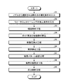
- FIG. 3 is a flowchart relating to the water jet peening stress analysis method according to the present embodiment.
- FIG. 4 is a diagram relating to the residual stress change depth in the depth direction from the construction target surface.
- FIG. 5 is a diagram relating to the residual stress change range in the horizontal direction of the construction target surface.
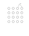
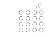
- FIG. 6 is an explanatory diagram showing an example of an arrangement pattern formed by a plurality of impact pressure load ranges.
- FIG. 7 is an explanatory diagram illustrating an example of an arrangement pattern corresponding to the number of loads.
- FIG. 1 is an explanatory view around a construction target surface that is an analysis target of the stress analysis apparatus according to the present embodiment.
- FIG. 2 is a block diagram showing a schematic configuration of the stress analysis apparatus according to the
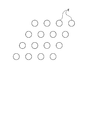
- FIG. 8 is an explanatory diagram showing an example of an arrangement pattern formed by a plurality of impact pressure load ranges.
- FIG. 9 is an explanatory diagram illustrating an example of an arrangement pattern corresponding to the number of loads.
- FIG. 10 is an explanatory diagram showing an example of an arrangement pattern formed by a plurality of impact pressure load ranges.
- FIG. 11 is an explanatory diagram illustrating an example of an arrangement pattern according to the number of loads.
- the stress analysis apparatus 1 is an apparatus that analyzes residual stress on a construction target surface when water jet peening for injecting high-pressure water (fluid) is performed on the construction target surface.
- water jet peening will be described with reference to FIG.
- FIG. 1 is an explanatory view around a construction target surface to be analyzed by the stress analysis apparatus according to the present embodiment.
- the high pressure water 6 in the water jet peening, the high pressure water 6 is jetted from the nozzle 5 toward the construction target surface P of the construction target 8.
- the construction target surface P is subjected to welding or the like, so that tensile stress remains.
- the high pressure water 6 includes bubbles 7 generated by cavitation.
- the bubbles 7 in the high-pressure water 6 collapse to generate an impact pressure, and a compressive stress is applied to the construction target surface P by the impact pressure. For this reason, the residual stress is removed from the construction target surface P where the tensile stress remains by applying the compressive stress by the water jet peening.
- FIG. 2 is a block diagram showing a schematic configuration of the stress analysis apparatus according to the present embodiment.
- the stress analysis apparatus 1 includes a calculation unit 11, a storage unit 12, an input unit 13, and an output unit 14.
- the arithmetic unit 11 is configured using hardware resources such as an integrated circuit including a CPU
- the storage unit 12 is configured using hardware resources such as a memory and a storage device.
- the input unit 13 is configured using hardware resources such as a keyboard and a mouse
- the output unit 14 is configured using hardware resources such as a display.
- the storage unit 12 stores a stress analysis program D1 for analyzing the residual stress on the construction target surface P and specification data D2 used for the analysis of the residual stress.
- the stress analysis program D1 is executed by the calculation unit 11 to analyze the residual stress of the construction target surface P based on the specification data D2.
- the specification data D2 includes, for example, data relating to the injection conditions of the high-pressure water 6 injected from the nozzle 5, data relating to the water jet peening construction conditions, data relating to the analysis conditions of the stress analysis of the construction target surface P, and the like.
- the specification data D2 includes data such as a function shown in FIGS. 4 and 5 below and yield stress used as the material strength of the construction target surface P.
- the yield stress of the construction target surface P is a known value by performing measurement or the like in advance.
- the input unit 13 is used to input various data used for residual stress analysis.
- the above-described specification data D2 is input to the stress analysis apparatus 1 via the input unit 13 as various data. Entered.
- the output unit 14 outputs an analysis result obtained by executing the stress analysis program D1.
- the calculation unit 11 executes the stress analysis program D1 stored in the storage unit 12 to analyze the residual stress on the construction target surface P based on the analysis conditions, and calculate the impact pressure as the analysis conditions, The impact pressure load range effective for removing the residual stress on the construction target surface P is calculated.
- FIG. 3 is a flowchart relating to the water jet peening stress analysis method according to the present embodiment.
- the construction target surface P is a flat surface, and water is jetted from the nozzle 5 toward one point on the surface.
- the stress analysis method shown in FIG. 3 includes a jet flow analysis step S3, an impact pressure calculation step S5, a range calculation step S6, an arrangement pattern setting step S7, a load frequency setting step S8, and a stress analysis step S9. Yes.
- the jet analysis step S3 the jet of the high-pressure water 6 injected from the nozzle 5 is analyzed based on the injection conditions of the high-pressure water 6 from the nozzle 5 in water jet peening.
- the impact pressure calculation step S5 the impact pressure of the high-pressure water 6 is calculated based on the analysis result in the jet flow analysis step S3.
- the range calculation step S6 the impact pressure load range is calculated from the functions shown in FIGS. 4 and 5 based on the calculated impact pressure and the yield stress in the construction target surface P stored in the storage unit 12.
- the arrangement pattern setting step S7 a plurality of impact pressure load ranges are arranged at predetermined intervals on the construction target surface P, and an arrangement pattern for each load is set.
- the load number setting step S8 the number of loads on the construction target surface P is set so that the position of the arrangement pattern is changed to cover the entire surface of the construction target surface P.
- the stress analysis step S9 the calculated impact pressure, the calculated impact pressure load range, the set arrangement pattern and the number of loads are used as analysis conditions, and the residual stress on the construction target surface P is analyzed based on the analysis conditions.
- the residual stress analysis operation will be specifically described with reference to FIG.
- step S1 the high pressure water injection condition in the water jet peening is input to the stress analysis apparatus 1 via the input unit 13 (step S1). That is, in step S ⁇ b> 1, parameters relating to the injection conditions necessary for analyzing the jet of the high-pressure water 6 from the nozzle 5 are input to the stress analyzer 1.
- the stress analysis apparatus 1 stores the injection condition in the storage unit 12 when a parameter related to the injection condition is input.
- the stress analyzer 1 is a model for analyzing the jet of the high-pressure water 6, a LES (Large Edydy Simulation) model for numerical analysis of turbulent flow, and numerically the behavior of water and many bubbles present in the water.
- a two-phase flow model for analysis and a cavitation model for numerical analysis of bubble behavior including generation and disappearance of bubbles are employed.
- step S1 for example, an evaporation coefficient, a condensation coefficient, a bubble nucleus generation site volume ratio, and a bubble diameter are set as parameters relating to the injection conditions.
- step S1 the atmospheric pressure (water depth at the construction site), the density and viscosity of the water, and the saturated vapor pressure are set to the same values as the conditions at the time of construction of the water jet peening. Furthermore, in step S1, the density of the steam when it is assumed that the steam is an ideal gas is set.
- step S2 construction conditions in water jet peening are input to the stress analysis apparatus 1 via the input unit 13 (step S2). That is, in step S ⁇ b> 2, data related to the construction conditions necessary for analyzing the jet of the high-pressure water 6 from the nozzle 5 is input to the stress analyzer 1.
- the stress analysis apparatus 1 stores data related to the construction condition in the storage unit 12.
- step S2 as data relating to the construction conditions, data relating to the construction object model 21 which is a model simulating the construction object 8 having the construction object surface P, data relating to the nozzle model 22 which is a model simulating the nozzle 5, Data relating to the coordinate system of the space in which the construction target model 21 and the nozzle model 22 are arranged is input to the stress analysis apparatus 1 (see FIG. 1).
- the data related to the construction target model 21 is that the construction target surface P is a flat surface, and high pressure water is jetted from the nozzle 5 toward one point on this surface. It is a model that becomes a plane.
- the data related to the nozzle model 22 is a model simulating the nozzle 5 used during construction of water jet peening, and may have any shape.
- the data relating to the coordinate system is based on the point where the injection axis 25 of the nozzle model 22 and the construction target surface P of the construction target model 21 intersect, and the direction in which the injection axis 25 extends from the origin is the Z axis, which is perpendicular to the Z axis. This is data in an XYZ coordinate system in which the axis is the X axis, the Z axis, and the axis perpendicular to the X axis is the Y axis.
- step S2 as the data relating to the construction conditions, the discharge pressure of the jet from the nozzle 5, the flow rate of the jet from the nozzle 5, the jetting distance of the jet (the distance from the outlet of the nozzle 5 to the construction target surface P) S, nozzle Data of the normal angle of the construction target surface P with respect to the injection shaft 25 of 5, the water depth of the construction target surface P, the temperature of the water, the jetting time of water from the nozzle 5, etc. are input to the stress analysis device 1 (FIG. 1).
- step S3 the calculation unit 11 of the stress analysis device 1 uses the parameters relating to the injection conditions set in step S1 and the analysis model, and based on the data relating to the construction conditions input in step S2, the high-pressure water 6 A jet flow analysis is executed (step S3).
- the calculation unit 11 derives the number of bubbles 7 generated and the number of bubbles 7 annihilated at each time on the construction target surface P, and the analysis result of the number of bubbles 7 generated and the number of bubbles 7 annihilated is derived. Is stored in the storage unit 12.
- the calculation unit 11 calculates the void rate and the collapse rate of the bubbles 7 at each position on the construction target surface P from the analysis result obtained by executing the jet flow analysis (step S4).
- the void ratio is the volume ratio of bubbles contained in a unit volume of water
- the collapse rate is the volume of bubbles that collapse in a unit time in the unit volume of water.
- the calculation unit 11 is based on the unit volume of water at each position on the construction target surface P, and the volume ratio per unit time of the bubbles 7 during the jetting time. Ask for.
- the calculating part 11 makes the average value of the volume ratio for every unit time the void ratio.
- the calculation unit 11 executes the construction from the number of disappearances of the bubbles 7 at each time in the unit volume of water at each position on the construction target surface P. In the unit volume of water at each position on the target surface P, the volume of the bubble 7 that collapses in the unit time including the corresponding time is obtained. And the calculating part 11 uses the average value of the volume of the bubble 7 which collapses in each unit time as a decay rate.
- step S5 impact pressure calculation step.
- the impact pressure is P
- the collapse rate of the bubble 7 is ⁇
- the void rate of the bubble 7 is f
- the coefficient depending on the water depth and the flow rate of the jet is k
- the calculation unit 11 of the stress analysis apparatus 1 calculates the impact pressure load range from the functions shown in FIGS. 4 and 5 based on the calculated impact pressure and the yield stress stored in the storage unit 12. Is calculated (step S6: range calculation step).
- the impact pressure load range is a range in which an effective impact pressure can be applied when removing the residual stress generated on the construction target surface P. That is, the impact pressure load range is a range in which the residual stress on the construction target surface P is zero, and specifically, a range of peening marks of the bubbles 7. In this impact pressure load range, since the bubbles 7 are spherical, the impact pressure load range that is an ideal shape that acts on the construction target surface P is a circular range.
- FIG. 4 is a diagram relating to the residual stress change depth in the depth direction from the construction target surface
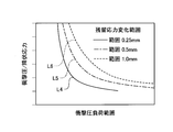
- FIG. 5 is a diagram relating to the residual stress change range in the horizontal direction of the construction target surface. 4 and 5, the vertical axis represents the impact pressure / yield stress, and the horizontal axis represents the impact pressure load range.
- the functions in FIGS. 4 and 5 are functions obtained in advance by experiments or the like.
- the residual stress change depth is a depth at which the residual stress can be removed in the depth direction from the origin of the construction target surface P, and this depth is changed.
- the residual stress change range is a range in which the residual stress can be removed in the horizontal direction from the origin of the construction target surface P, and this range is changed. For this reason, a plurality of functions are prepared in accordance with the residual stress change depth and the residual stress change range.
- L1 in FIG. 4 is a line in which the residual stress changes from the origin of the construction target surface P to a depth of 0.5 mm, and the residual stress is reduced.
- L2 is a line in which the residual stress changes from the origin of the construction target surface P to a depth of 1.0 mm, and the residual stress is reduced.
- L3 is a line in which the residual stress change depth is from the origin of the construction target surface P to a depth of 1.5 mm, and the residual stress is reduced.
- L1 to L3 are functions that increase the impact pressure / yield stress in order to increase the residual stress change depth when the impact pressure load range is constant.
- L1 to L3 are functions that widen the impact pressure load range in order to increase the residual stress change depth when the impact pressure / yield stress is constant.
- L4 in FIG. 5 is a line in which the residual stress change range is a range of 0.25 mm from the origin of the construction target surface P, and the residual stress is reduced.
- L5 is a line in which the range of 0.5 mm from the origin of the construction target surface P is the residual stress change range, and the residual stress is reduced.
- L6 is a line in which the range of 1.0 mm from the origin of the construction target surface P is the residual stress change range, and the residual stress is reduced.
- the residual stress change range is a range in which compressive stress is applied by water jet peening.
- L4 to L6 are functions that increase the impact pressure / yield stress in order to widen the residual stress change range.
- L4 to L6 are functions that widen the impact pressure load range in order to widen the residual stress change range when the impact pressure / yield stress is constant.
- FIG. 6 is an explanatory diagram showing an arrangement pattern formed by a plurality of impact pressure load ranges.
- the impact pressure load range E is a circular range.
- the impact pressure load ranges E are arranged in the row direction (left and right direction in FIG. 6) with a predetermined (one) interval, and a plurality of impact pressure load ranges E arranged in the row direction. Are arranged side by side in the row direction (vertical direction in FIG. 6) with a predetermined (one) interval.
- the plurality of impact pressure load ranges E arranged in the column direction are arranged adjacent to each other so as to overlap in the row direction. That is, the arrangement pattern is a pattern in which a plurality of impact pressure load ranges E are arranged in a grid pattern.
- the predetermined interval in the column direction and the row direction is the diameter of the impact pressure load range E that is circular.
- step S8 load number setting step
- the arrangement pattern of FIG. 6 is set at different positions so that the predetermined area of the construction target surface P is entirely covered.
- the number of loads is eight. Specifically, the arrangement pattern in which the number of loads is from the first to the fourth is arranged so that the impact pressure load range E does not overlap. The arrangement pattern in which the number of loads is from the fifth to the eighth is arranged so that the impact pressure load range E overlaps the arrangement pattern from the first to the fourth.
- the second arrangement pattern has one impact pressure load range E in the column direction (impact pressure load) with respect to the first arrangement pattern.
- the position is moved by the diameter of the range E).
- the third arrangement pattern is a position obtained by moving the impact pressure load range E by one in the row direction with respect to the first arrangement pattern.
- the fourth arrangement pattern is a position where the impact pressure load range E is moved by one by one in the column direction and the row direction with respect to the first arrangement pattern.
- the fifth arrangement pattern is a position obtained by moving the impact pressure load range E by a half (the radius of the impact pressure load range E) by half in the column direction and the row direction with respect to the first arrangement pattern. Yes. Based on the fifth arrangement pattern, the sixth arrangement pattern is equivalent to one impact pressure load range E in the column direction (the diameter of the impact pressure load range E) with respect to the fifth arrangement pattern. The position is only moved.
- the seventh arrangement pattern is a position where the impact pressure load range E is moved by one in the row direction with respect to the fifth arrangement pattern.
- the eighth arrangement pattern is a position where the impact pressure load range E is moved by one by one in the column direction and the row direction with respect to the fifth arrangement pattern.
- the calculation unit 11 of the stress analyzer 1 can set the number of loads such that the predetermined area of the construction target surface P is entirely covered by setting the number of loads shown in FIG.
- step S8 the calculation unit 11 of the stress analysis device 1 performs the construction target surface P based on the analysis conditions including the calculated magnitude of the impact pressure, the calculated impact pressure load range, the set arrangement pattern, and the number of loads. Residual stress analysis is performed at step S9: stress analysis step.
- the analysis condition includes time until the impact pressure of the bubble 7 rises to a predetermined impact pressure (impact pressure rise time).
- FEM finite element method
- step S9 the data regarding the construction target model 21 which is an axially symmetric model simulating the construction target 8 having the construction target surface P, the data regarding the nozzle model 22 which is the axially symmetric model simulating the nozzle 5, and the construction target Data relating to the coordinate system of the space in which the model 21 and the nozzle model 22 are arranged is input to the stress analysis apparatus 1 as an analysis condition.
- the data relating to the coordinate system is data of a polar coordinate system centered on the Z axis.
- region of the construction target surface P is calculated by repeatedly performing FEM analysis for every load based on the set load frequency
- the calculation unit 11 of the stress analyzer 1 uses the functions shown in FIGS. 4 and 5 to calculate the impact pressure and the material strength obtained by measurement or the like. Based on this, it is possible to calculate the impact pressure load range necessary for the stress analysis. And the calculating part 11 of the stress analysis apparatus 1 can analyze the residual stress of the construction target surface P by using the calculated impact pressure, the impact pressure load range, the set arrangement pattern and the number of loads as analysis conditions. Therefore, the calculation unit 11 of the stress analyzer 1 can quickly calculate the impact pressure load range from the functions shown in FIGS. 4 and 5 even when the material strength on the construction target surface P is different. Thereby, the residual stress in the construction target surface P can be quickly analyzed.
- the impact pressure load range can be quickly calculated from the impact pressure and the yield stress by using the functions shown in FIGS.
- region of the construction target surface P can be efficiently calculated by setting the load frequency shown in FIG. it can.
- the arrangement pattern shown in FIG. 6 and the load count shown in FIG. 7 are set.
- the present invention is not limited to this.
- the arrangement pattern shown in FIG. 10 and the load count shown in FIG. 11 may be set.
- 8 and 10 are explanatory diagrams illustrating an example of an arrangement pattern formed by a plurality of impact pressure load ranges
- FIGS. 9 and 11 are explanatory diagrams illustrating an example of an arrangement pattern according to the number of loads. .
- the impact pressure load range E is arranged in the row direction (left and right direction in FIG. 8) with a predetermined (one) interval, and a plurality of shocks arranged in the row direction.
- This is a pattern in which the pressure load range E is arranged in the row direction (vertical direction in FIG. 8) with a predetermined (one) interval.
- one impact pressure load range E adjacent in the row direction is disposed between the other impact pressure load ranges E adjacent in the row direction. That is, the arrangement pattern is a pattern in which a plurality of impact pressure load ranges E are arranged in a staggered manner.
- the predetermined interval in the column direction and the row direction is the diameter of the impact pressure load range E that is circular.
- the positions are changed so that the predetermined area of the construction target surface P is entirely covered, as in the case of using the arrangement pattern shown in FIG. 6. Is set.
- the number of loads is eight. Specifically, the arrangement pattern in which the number of loads is from the first to the fourth is arranged so that the impact pressure load range E does not overlap. The arrangement pattern in which the number of loads is from the fifth to the eighth is arranged so that the impact pressure load range E overlaps the arrangement pattern from the first to the fourth.
- the second arrangement pattern has one impact pressure load range E in the column direction (impact pressure load) with respect to the first arrangement pattern.
- the position is moved by the diameter of the range E).
- the impact pressure load range E is moved by ⁇ 3r in the row direction with respect to the first arrangement pattern, and half in the column direction ( The position is moved by the radius r of the impact pressure load range E).
- the impact pressure load range E is moved by ⁇ 3r in the row direction with respect to the first arrangement pattern, and half the impact pressure load range E in the column direction opposite to the third (impact pressure load range E The position is moved by the radius r).
- the fifth arrangement pattern is a position obtained by moving the impact pressure load range E by 1 ⁇ 2r in the column direction and by ⁇ 3 / 2r in the row direction with respect to the first arrangement pattern. Note that the number of loads from the fifth time to the eighth time is the same as the first time to the fourth time, and thus the description thereof is omitted.
- the impact pressure load range E is arranged in the row direction (left and right direction in FIG. 10) with a predetermined interval, and a plurality of impact pressure load ranges E arranged in the row direction are arranged.
- the pattern is arranged in the row direction (vertical direction in FIG. 10) with a predetermined interval.
- the predetermined interval in the column direction is an interval smaller than the diameter of the impact pressure load range E that is circular
- the predetermined interval in the row direction is an interval smaller than the predetermined interval in the column direction.
- This interval is an interval at which the number of loads shown in FIG. 11 can be set using the arrangement pattern shown in FIG. 10.
- the predetermined interval in the column direction is (2 ⁇ 3-2) r (r Is the radius of the impact pressure load range E), and the predetermined interval in the row direction is the radius of the impact pressure load range E.
- the plurality of impact pressure load ranges E arranged in the column direction are arranged adjacent to each other so as to overlap in the row direction. That is, the arrangement pattern is a pattern in which a plurality of impact pressure load ranges E are arranged in a grid pattern.
- the position of the arrangement pattern is such that all predetermined areas of the construction target surface P are covered, as in the case of using the arrangement pattern shown in FIG. 6.
- the number of loads is four.
- the second arrangement pattern is the second arrangement pattern between the impact pressure load ranges E of the first arrangement pattern in the column direction.
- the arrangement is such that the impact pressure load range E is located.
- the third arrangement pattern is located between the impact pressure load range E of the first arrangement pattern and the impact pressure load range E of the second arrangement pattern in the column direction with respect to the first arrangement pattern.
- the impact pressure load range E is moved by 3/4 (the radius of the impact pressure load range E ⁇ 1.5).
- the fourth arrangement pattern is arranged such that the impact pressure load range E of the fourth arrangement pattern is located between the impact pressure load ranges E of the third arrangement pattern in the column direction.
- the number of loads can be suppressed and set as shown in FIG. 11, and the residual stress in a predetermined region of the construction target surface P can be calculated efficiently. can do.
Landscapes
- Engineering & Computer Science (AREA)
- Mechanical Engineering (AREA)
- Investigating Strength Of Materials By Application Of Mechanical Stress (AREA)
- Testing Of Devices, Machine Parts, Or Other Structures Thereof (AREA)
Abstract
ノズルから施工対象面に向けて流体を噴射するウォータジェットピーニングの施工対象面における残留応力を解析するウォータジェットピーニングの応力解析方法であって、噴流解析工程(S3)と、衝撃圧算出工程(S5)と、衝撃圧負荷範囲と衝撃圧と材料強度との相関関係から、衝撃圧負荷範囲を算出する範囲算出工程(S6)と、施工対象面に対して衝撃圧負荷範囲を複数配置した配置パターンを設定する配置パターン設定工程(S7)と、配置パターンの位置を異ならせて、施工対象面への負荷回数を設定する負荷回数設定工程(S8)と、算出した衝撃圧、衝撃圧負荷範囲、設定した配置パターン及び負荷回数を解析条件として、施工対象面における残留応力を解析する応力解析工程(S9)と、を備える。
Description
本発明は、高圧水等の流体を施工対象面に噴射して、施工対象面を改質するウォータジェットピーニングの応力解析方法、応力解析装置及び応力解析プログラムに関するものである。
構造物は、溶接等が行われることによって、その表面に引張残留応力が生じる。ウォータジェットピーニングは、構造物の表面に生じている引張残留応力を除去するために、構造物の表面に対して高圧水を噴射する。つまり、ウォータジェットピーニングは、構造物の表面に対して高圧水を噴射することで、高圧水中で発生する微細な気泡が崩壊することで生じる衝撃波により、構造物の表面に圧縮応力を与える。このため、構造物は、ウォータジェットピーニングにより引張残留応力が除去される。これにより、施工対象面は、ウォータジェットピーニングにより改質されることで、応力腐食割れが抑制される。
ここで、ウォータジェットピーニングが施工される施工対象物の残留応力を評価するウォータジェットピーニングの残留応力評価方法が知られている(例えば、特許文献1参照)。この残留応力評価方法では、ノズルから噴出する噴流を解析して、気泡の気泡内圧と気泡数密度の予測結果に基づいて施工面上の気泡の崩壊圧を算出し、この崩壊圧を用いて施工面上の残留応力を算出している。
ところで、ウォータジェットピーニングが施工される施工対象物の材料強度は異なる場合がある。施工対象物の材料強度が異なると、ノズルから噴出する噴流条件が同じである場合であっても、施工対象面の残留応力の除去に有効な衝撃圧負荷範囲が異なる。このため、施工対象物の材料強度毎に、残留応力を評価しなければならず、残留応力の評価に多大な時間を要することとなる。
そこで、本発明は、施工対象面における材料強度が異なる場合であっても、施工対象面の残留応力を迅速に解析することができるウォータジェットピーニングの応力解析方法、応力解析装置及び応力解析プログラムを提供することを課題とする。
本発明のウォータジェットピーニングの応力解析方法は、ノズルから施工対象面に向けて流体を噴射するウォータジェットピーニングの前記施工対象面における残留応力を解析するウォータジェットピーニングの応力解析方法であって、前記ノズルから噴射される前記流体の噴流を解析する噴流解析工程と、前記噴流解析工程の解析結果に基づいて、前記流体の衝撃圧を算出する衝撃圧算出工程と、前記施工対象面における前記残留応力の除去に有効な衝撃圧負荷範囲と、前記衝撃圧と、前記施工対象面における材料強度との相関関係から、前記衝撃圧及び前記材料強度に基づいて、前記衝撃圧負荷範囲を算出する範囲算出工程と、前記施工対象面に対して、前記衝撃圧負荷範囲を所定の間隔を空けて複数配置した配置パターンを設定する配置パターン設定工程と、前記配置パターンの位置を異ならせて、前記施工対象面の所定の領域が全て覆われるように、前記施工対象面への負荷回数を設定する負荷回数設定工程と、算出した前記衝撃圧、前記衝撃圧負荷範囲、設定した前記配置パターン及び前記負荷回数を解析条件とし、前記解析条件に基づいて、前記施工対象面における残留応力を解析する応力解析工程と、を備えることを特徴とする。
また、本発明のウォータジェットピーニングの応力解析装置は、ノズルから施工対象面に向けて流体を噴射するウォータジェットピーニングの前記施工対象面における残留応力を解析するウォータジェットピーニングの応力解析装置であって、解析条件に基づいて、前記施工対象面における残留応力を解析する演算部と、前記施工対象面における前記残留応力の除去に有効な衝撃圧負荷範囲、噴射される前記流体による前記施工対象面への衝撃圧、及び前記施工対象面における材料強度の相関関係と、前記材料強度と、を記憶する記憶部と、を備え、前記演算部は、前記ノズルから噴射される前記流体の噴流を解析する噴流解析工程と、前記噴流解析工程の解析結果に基づいて、前記流体の衝撃圧を算出する衝撃圧算出工程と、前記相関関係から、算出した前記衝撃圧及び記憶した前記材料強度に基づいて、前記衝撃圧負荷範囲を算出する範囲算出工程と、前記施工対象面に対して、前記衝撃圧負荷範囲を所定の間隔を空けて複数配置した配置パターンを設定する配置パターン設定工程と、前記配置パターンの位置を異ならせて、前記施工対象面の所定の領域が全て覆われるように、前記施工対象面への負荷回数を設定する負荷回数設定工程と、算出した前記衝撃圧、前記衝撃圧負荷範囲、設定した前記配置パターン及び前記負荷回数を解析条件とし、前記解析条件に基づいて、前記施工対象面における残留応力を解析する応力解析工程と、を実行することを特徴とする。
さらに、本発明のウォータジェットピーニングの応力解析プログラムは、ノズルから施工対象面に向けて流体を噴射するウォータジェットピーニングの前記施工対象面における残留応力を解析するウォータジェットピーニングの応力解析装置の演算部に、前記ノズルから噴射される前記流体の噴流を解析する噴流解析工程と、前記噴流解析工程の解析結果に基づいて、前記流体の衝撃圧を算出する衝撃圧算出工程と、前記施工対象面における前記残留応力の除去に有効な衝撃圧負荷範囲と、前記衝撃圧と、前記施工対象面における材料強度との相関関係から、前記衝撃圧及び前記材料強度に基づいて、前記衝撃圧負荷範囲を算出する範囲算出工程と、前記施工対象面に対して、前記衝撃圧負荷範囲を所定の間隔を空けて複数配置した配置パターンを設定する配置パターン設定工程と、前記配置パターンの位置を異ならせて、前記施工対象面の所定の領域が全て覆われるように、前記施工対象面への負荷回数を設定する負荷回数設定工程と、算出した前記衝撃圧、前記衝撃圧負荷範囲、設定した前記配置パターン及び前記負荷回数を解析条件とし、前記解析条件に基づいて、前記施工対象面における残留応力を解析する応力解析工程と、を実行させることを特徴とする。
この構成によれば、衝撃圧と材料強度と衝撃圧負荷範囲との相関関係から、算出した衝撃圧と計測等によって得られた材料強度とに基づいて、応力解析に必要な衝撃圧負荷範囲を算出することができる。そして、算出した衝撃圧、衝撃圧負荷範囲、設定した配置パターン及び負荷回数を解析条件として、施工対象面の残留応力を解析することができる。このため、施工対象面における材料強度が異なる場合であっても、上記の相関関係から、衝撃圧負荷範囲を迅速に算出することができ、これにより、施工対象面における残留応力を迅速に解析することができる。
また、前記衝撃圧負荷範囲と前記衝撃圧と前記材料強度との相関関係は、前記衝撃圧/前記施工対象面の降伏応力と、前記衝撃圧負荷範囲との関数で表され、前記関数は、前記残留応力を除去可能な深さである残留応力変化深さ、及び前記残留応力を除去可能な範囲である残留応力変化範囲に応じて、複数用意されることが、好ましい。
この構成によれば、関数を用いることで、必要な残留応力変化深さ及び残留応力変化範囲に対して、衝撃圧及び降伏応力から、衝撃圧負荷範囲を迅速に算出することができる。
また、前記衝撃圧負荷範囲は、円形であり、前記配置パターン設定工程における所定の前記間隔は、前記衝撃圧負荷範囲の直径であり、前記配置パターンは、前記衝撃圧負荷範囲を、前記間隔を空けて列方向に並べて配置すると共に、複数の前記衝撃圧負荷範囲を、前記間隔を空けて行方向に並べて配置することで、複数の衝撃圧負荷範囲を格子状に配置したものであることが、好ましい。
この構成によれば、施工対象面の所定の領域における残留応力を、効率良く算出することができる。なお、衝撃圧負荷範囲は、気泡の崩壊によって発生することから、理想的な形状として、円形としている。
以下に、本発明に係る実施形態を図面に基づいて詳細に説明する。なお、この実施形態によりこの発明が限定されるものではない。また、下記実施形態における構成要素には、当業者が置換可能かつ容易なもの、あるいは実質的に同一のものが含まれる。さらに、以下に記載した構成要素は適宜組み合わせることが可能であり、また、実施形態が複数ある場合には、各実施形態を組み合わせることも可能である。
[実施形態]
本実施形態に係る応力解析装置1は、高圧水(流体)を噴射するウォータジェットピーニングを施工対象面に施工したときの、施工対象面における残留応力を解析する装置である。先ずは、応力解析装置1を説明する前に、図1を参照して、ウォータジェットピーニングについて説明する。
本実施形態に係る応力解析装置1は、高圧水(流体)を噴射するウォータジェットピーニングを施工対象面に施工したときの、施工対象面における残留応力を解析する装置である。先ずは、応力解析装置1を説明する前に、図1を参照して、ウォータジェットピーニングについて説明する。
図1は、本実施形態に係る応力解析装置の解析対象となる施工対象面周りの説明図である。図1に示すように、ウォータジェットピーニングは、施工対象物8の施工対象面Pに向けて、ノズル5から高圧水6を噴射する。ここで、施工対象面Pは、溶接等が行われることで、引張応力が残留している。高圧水6には、キャビテーションにより生じる気泡7が含まれる。高圧水6中の気泡7は、崩壊することで衝撃圧を発生させ、この衝撃圧により、施工対象面Pに対して圧縮応力を与える。このため、引張応力が残留する施工対象面Pは、ウォータジェットピーニングにより圧縮応力が与えられることで、残留応力が除去される。
次に、図2を参照して、応力解析装置1について説明する。図2は、本実施形態に係る応力解析装置の概略的な構成を示すブロック図である。応力解析装置1は、演算部11と、記憶部12と、入力部13と、出力部14とを備えている。なお、演算部11は、CPUを含む集積回路等のハードウェア資源を用いて構成され、記憶部12は、メモリおよび記憶装置等のハードウェア資源を用いて構成されている。また、入力部13は、キーボード及びマウス等のハードウェア資源を用いて構成され、出力部14は、ディスプレイ等のハードウェア資源を用いて構成されている。
記憶部12は、施工対象面Pにおける残留応力を解析するための応力解析プログラムD1と、残留応力の解析に使用する諸元データD2とを記憶している。応力解析プログラムD1は、演算部11で実行されることにより、諸元データD2に基づく施工対象面Pの残留応力を解析する。諸元データD2としては、例えば、ノズル5から噴射される高圧水6の噴射条件に関するデータ、ウォータジェットピーニングの施工条件に関するデータ、施工対象面Pの応力解析の解析条件に関するデータ等がある。具体的に、諸元データD2としては、下記の図4及び図5に示す関数、施工対象面Pの材料強度として用いられる降伏応力等のデータがある。施工対象面Pの降伏応力は、予め計測等が行われることにより、既知の値となっている。
入力部13は、残留応力の解析に用いられる各種データを入力するために使用されるものであり、例えば、各種データとして上記の諸元データD2が、入力部13を介して応力解析装置1に入力される。出力部14は、応力解析プログラムD1を実行することで得られた解析結果を出力する。
演算部11は、記憶部12に記憶された応力解析プログラムD1を実行することで、解析条件に基づいて施工対象面Pにおける残留応力を解析する他、解析条件となる衝撃圧を算出したり、施工対象面Pにおける残留応力の除去に有効な衝撃圧負荷範囲を算出したりする。
次に、図3を参照して、演算部11により施工対象面Pの残留応力を解析する動作について説明する。図3は、本実施形態に係るウォータジェットピーニングの応力解析方法に関するフローチャートである。なお、以下では、説明を簡略化するため、施工対象面Pは平面であり、この面上の一点に向かってノズル5から水を噴射するものとする。
図3に示す応力解析方法は、噴流解析工程S3と、衝撃圧算出工程S5と、範囲算出工程S6と、配置パターン設定工程S7と、負荷回数設定工程S8と、応力解析工程S9とを含んでいる。噴流解析工程S3では、ウォータジェットピーニングにおけるノズル5からの高圧水6の噴射条件に基づいて、ノズル5から噴射される高圧水6の噴流を解析している。衝撃圧算出工程S5では、噴流解析工程S3の解析結果に基づいて、高圧水6の衝撃圧を算出している。範囲算出工程S6では、算出した衝撃圧及び記憶部12に記憶されている施工対象面Pにおける降伏応力に基づいて、図4及び図5に示す関数から衝撃圧負荷範囲を算出している。配置パターン設定工程S7では、施工対象面Pに対して、衝撃圧負荷範囲を所定の間隔を空けて複数配置して、1回の負荷毎の配置パターンを設定している。負荷回数設定工程S8では、配置パターンの位置を異ならせて、施工対象面Pの全面が覆われるように、施工対象面Pへの負荷回数を設定している。応力解析工程S9では、算出した衝撃圧、算出した衝撃圧負荷範囲、設定した配置パターン及び負荷回数を解析条件とし、この解析条件に基づいて、施工対象面Pにおける残留応力を解析している。以下、図3を参照して、残留応力の解析動作について具体的に説明する。
先ず、応力解析装置1には、入力部13を介して、ウォータジェットピーニングにおける高圧水の噴射条件が入力される(ステップS1)。つまり、ステップS1では、ノズル5からの高圧水6の噴流を解析するために必要な噴射条件に関するパラメータが、応力解析装置1に入力される。応力解析装置1は、噴射条件に関するパラメータが入力されると、記憶部12に噴射条件を記憶する。
ここで、応力解析装置1は、高圧水6の噴流を解析するモデルとして、乱流を数値解析するためのLES(Large Eddy Simulation)モデルと、水と水中に存在する多数の気泡の挙動を数値解析するための2相流モデルと、気泡の発生や消滅等を含む気泡の挙動を数値解析するためのキャビテーションモデルとを採用している。このため、ステップS1では、噴射条件に関するパラメータとして、例えば、蒸発係数、凝縮係数、気泡核生成部位体積率、気泡径が設定される。また、ステップS1では、雰囲気気圧(施工部位の水深)、水の密度及び粘性、飽和蒸気圧が、ウォータジェットピーニングの施工時における条件と同じ値となるように設定される。さらに、ステップS1では、蒸気が理想気体であると仮定したときの蒸気の密度が設定される。
次に、応力解析装置1には、入力部13を介して、ウォータジェットピーニングにおける施工条件が入力される(ステップS2)。つまり、ステップS2では、ノズル5からの高圧水6の噴流を解析するために必要な施工条件に関するデータが、応力解析装置1に入力される。応力解析装置1は、施工条件が入力されると、記憶部12に施工条件に関するデータを記憶する。
ここで、ステップS2では、施工条件に関するデータとして、施工対象面Pを有する施工対象物8を模擬したモデルである施工対象モデル21に関するデータ、ノズル5を模擬したモデルであるノズルモデル22に関するデータ、施工対象モデル21及びノズルモデル22が配置される空間の座標系に関するデータが、応力解析装置1に入力される(図1参照)。
施工対象モデル21に関するデータは、上記したように、施工対象面Pが平面であり、この面上の一点に向かってノズル5から高圧水を噴射することから、施工対象モデル21の施工対象面Pが平面となるようなモデルとなっている。また、ノズルモデル22に関するデータは、ウォータジェットピーニングの施工時に使用されるノズル5を模擬したモデルであり、いずれの形状であってもよい。座標系に関するデータは、ノズルモデル22の噴射軸25と施工対象モデル21の施工対象面Pとが交差する点を原点とし、原点から噴射軸25が延びる方向をZ軸、このZ軸に垂直な軸をX軸、Z軸及びX軸に垂直な軸をY軸とするXYZ座標系のデータである。
また、ステップS2では、施工条件に関するデータとして、ノズル5からの噴流の吐出圧、ノズル5からの噴流の流量、噴流の噴射距離(ノズル5の出口から施工対象面Pまでの距離)S、ノズル5の噴射軸25に対する施工対象面Pの法線の角度、施工対象面Pの水深、水の温度、ノズル5からの水の噴射時間等のデータが、応力解析装置1に入力される(図1参照)。
ステップS2の実行後、応力解析装置1の演算部11は、ステップS1で設定した噴射条件に関するパラメータと解析モデルとを使用し、ステップS2で入力した施工条件に関するデータに基づいて、高圧水6の噴流解析を実行する(ステップS3)。演算部11は、噴流解析において、施工対象面P上での各時刻における気泡7の発生数及び気泡7の消滅数を導出し、導出した気泡7の発生数及び気泡7の消滅数を解析結果として、記憶部12に記憶させる。
次に、演算部11は、噴流解析を実行して得られる解析結果から、施工対象面P上の各位置における気泡7のボイド率及び崩壊率を算出する(ステップS4)。ここで、ボイド率とは、水の単位体積に含まれる気泡の体積率であり、崩壊率とは、水の単位体積中で単位時間に崩壊する気泡の体積である。演算部11は、記憶部12に記憶された噴流解析の解析結果に基づいて、施工対象面P上の各位置における水の単位体積中で、噴射時間中における気泡7の単位時間毎の体積率を求める。そして、演算部11は、単位時間毎の体積率の平均値をボイド率とする。また、演算部11は、記憶部12に記憶された噴流解析の解析結果に基づいて、施工対象面P上の各位置における水の単位体積中で、各時刻における気泡7の消滅数から、施工対象面P上の各位置における水の単位体積中で、該当時刻を含む単位時間で崩壊する気泡7の体積を求める。そして、演算部11は、各単位時間で崩壊する気泡7の体積の平均値を崩壊率とする。
ステップS4の実行後、応力解析装置1の演算部11は、ボイド率及び崩壊率に基づいて、衝撃圧を算出する(ステップS5:衝撃圧算出工程)。ここで、衝撃圧をPとし、気泡7の崩壊率をηとし、気泡7のボイド率をfとし、水深と噴流の流量に依存する係数をkとすると、衝撃圧Pは、経験則として、「P=k×η×f」で表すことができる。
ステップS5の実行後、応力解析装置1の演算部11は、算出した衝撃圧と、記憶部12に記憶された降伏応力とに基づいて、図4及び図5に示す関数から、衝撃圧負荷範囲を算出する(ステップS6:範囲算出工程)。ここで、衝撃圧負荷範囲とは、施工対象面P上において発生する残留応力を除去するにあたって、有効な衝撃圧を与えることが可能な範囲である。つまり、衝撃圧負荷範囲とは、施工対象面Pにおける残留応力が0となるような範囲であり、具体的には、気泡7のピーニング痕の範囲となる。この衝撃圧負荷範囲は、気泡7が球状であることから、施工対象面P上において作用する理想的な形状となる衝撃圧負荷範囲は、円形の範囲となる。
ここで、図4及び図5の関数について説明する。図4は、施工対象面からの深さ方向における残留応力変化深さに関する図であり、図5は、施工対象面の水平方向における残留応力変化範囲に関する図である。図4及び図5において、その縦軸は、衝撃圧/降伏応力となっており、その横軸が衝撃圧負荷範囲となっている。図4及び図5の関数は、予め実験等により求められた関数である。なお、残留応力変化深さとは、施工対象面Pの原点から深さ方向において残留応力を除去可能な深さであり、この深さを変化させたものとなっている。また、残留応力変化範囲とは、施工対象面Pの原点から水平方向において残留応力を除去可能な範囲であり、この範囲を変化させたものとなっている。このため、関数は、残留応力変化深さ及び残留応力変化範囲に応じて、複数用意されている。
ここで、図4のL1は、施工対象面Pの原点から0.5mmの深さまでが残留応力変化深さとなっており、残留応力が低減するラインである。L2は、施工対象面Pの原点から1.0mmの深さまでが残留応力変化深さとなっており、残留応力が低減するラインである。L3は、施工対象面Pの原点から1.5mmの深さまでが残留応力変化深さとなっており、残留応力が低減するラインである。図4に示すように、L1~L3は、衝撃圧負荷範囲が一定である場合、残留応力変化深さを深くするためには、衝撃圧/降伏応力が大きくなる関数となっている。また、L1~L3は、衝撃圧/降伏応力が一定である場合、残留応力変化深さを深くするためには、衝撃圧負荷範囲を広くする関数となっている。
また、図5のL4は、施工対象面Pの原点から0.25mmの範囲が残留応力変化範囲となっており、残留応力が低減するラインである。L5は、施工対象面Pの原点から0.5mmの範囲が残留応力変化範囲となっており、残留応力が低減するラインである。L6は、施工対象面Pの原点から1.0mmの範囲が残留応力変化範囲となっており、残留応力が低減するラインである。なお、残留応力変化範囲は、ウォータジェットピーニングにより圧縮応力が与えられる範囲である。図5に示すように、L4~L6は、衝撃圧負荷範囲が一定の範囲である場合、残留応力変化範囲を広くするためには、衝撃圧/降伏応力が大きくなる関数となっている。また、L4~L6は、衝撃圧/降伏応力が一定である場合、残留応力変化範囲を広くするためには、衝撃圧負荷範囲を広くする関数となっている。
ステップS6の実行後、応力解析装置1の演算部11は、算出した衝撃圧負荷範囲Eに基づいて、図6に示す所定の配置パターンを設定する(ステップS7:配置パターン設定工程)。ここで、図6は、複数の衝撃圧負荷範囲により形成される配置パターンを示す説明図である。図6に示すように、衝撃圧負荷範囲Eは円形の範囲となっている。配置パターンは、衝撃圧負荷範囲Eを、所定の(1個分の)間隔を空けて列方向(図6の左右方向)に並べて配置すると共に、列方向に並んだ複数の衝撃圧負荷範囲Eを、所定の(1個分の)間隔を空けて行方向(図6の上下方向)に並べて配置したパターンとなっている。また、列方向に並ぶ複数の衝撃圧負荷範囲Eは、行方向において重なり合うように、隣接して配置される。つまり、配置パターンは、複数の衝撃圧負荷範囲Eを格子状に配置したパターンとなっている。ここで、列方向及び行方向における所定の間隔は、円形となる衝撃圧負荷範囲Eの直径である。
ステップS7の実行後、応力解析装置1の演算部11は、設定した配置パターンに基づく負荷回数を設定する(ステップS8:負荷回数設定工程)。図7に示すように、図6の配置パターンは、施工対象面Pの所定の領域が全て覆われるように、位置を異ならせて設定される。本実施形態において、図6の格子状となる配置パターンを用いる場合、負荷回数は8回となる。具体的に、負荷回数が1回目から4回目となる配置パターンは、衝撃圧負荷範囲Eが重なり合わないように配置される。負荷回数が5回目から8回目となる配置パターンは、1回目から4回目となる配置パターンに、衝撃圧負荷範囲Eが重なり合うように配置される。
具体的に、負荷回数が1回目となる配置パターンを基準とすると、2回目の配置パターンは、1回目の配置パターンに対して、衝撃圧負荷範囲Eを列方向に1個分(衝撃圧負荷範囲Eの直径分)だけ移動させた位置となっている。3回目の配置パターンは、1回目の配置パターンに対して、衝撃圧負荷範囲Eを行方向に1個分だけ移動させた位置となっている。4回目の配置パターンは、1回目の配置パターンに対して、衝撃圧負荷範囲Eを列方向及び行方向に1個分ずつだけ移動させた位置となっている。
5回目の配置パターンは、1回目の配置パターンに対して、衝撃圧負荷範囲Eを列方向及び行方向に半個分(衝撃圧負荷範囲Eの半径分)ずつだけ移動させた位置となっている。そして、5回目の配置パターンを基準とすると、6回目の配置パターンは、5回目の配置パターンに対して、衝撃圧負荷範囲Eを列方向に1個分(衝撃圧負荷範囲Eの直径分)だけ移動させた位置となっている。7回目の配置パターンは、5回目の配置パターンに対して、衝撃圧負荷範囲Eを行方向に1個分だけ移動させた位置となっている。8回目の配置パターンは、5回目の配置パターンに対して、衝撃圧負荷範囲Eを列方向及び行方向に1個分ずつだけ移動させた位置となっている。このように、応力解析装置1の演算部11は、図7に示す負荷回数を設定することで、施工対象面Pの所定の領域が全て覆われるような、負荷回数を設定できる。
ステップS8の実行後、応力解析装置1の演算部11は、算出した衝撃圧の大きさ、算出した衝撃圧負荷範囲、設定した配置パターン及び負荷回数を含む解析条件に基づいて、施工対象面Pにおける残留応力解析を実行する(ステップS9:応力解析工程)。また、解析条件としては、気泡7の衝撃圧が所定の衝撃圧まで上昇するまでの時間(衝撃圧の上昇時間)を含む。この応力解析工程では、軸対称モデルを用いた有限要素法(FEM:Finite Element Method)に基づく解析を行っている。このため、ステップS9では、施工対象面Pを有する施工対象物8を模擬した軸対称モデルである施工対象モデル21に関するデータ、ノズル5を模擬した軸対称モデルであるノズルモデル22に関するデータ、施工対象モデル21及びノズルモデル22が配置される空間の座標系に関するデータが、解析条件として応力解析装置1に入力される。なお、座標系に関するデータは、Z軸を中心とする極座標系のデータである。そして、応力解析工程S9では、設定した負荷回数に基づいて、負荷毎にFEM解析を繰り返し実行することで、施工対象面Pの所定の領域における残留応力を算出する。
以上のように、本実施形態によれば、応力解析装置1の演算部11は、図4及び図5に示す関数を用いて、算出した衝撃圧と,計測等によって得られた材料強度とに基づいて、応力解析に必要な衝撃圧負荷範囲を算出することができる。そして、応力解析装置1の演算部11は、算出した衝撃圧、衝撃圧負荷範囲、設定した配置パターン及び負荷回数を解析条件として、施工対象面Pの残留応力を解析することができる。このため、応力解析装置1の演算部11は、施工対象面Pにおける材料強度が異なる場合であっても、図4及び図5に示す関数から、衝撃圧負荷範囲を迅速に算出することができ、これにより、施工対象面Pにおける残留応力を迅速に解析することができる。
また、本実施形態によれば、図4及び図5に示す関数を用いることで、衝撃圧及び降伏応力から、衝撃圧負荷範囲を迅速に算出することができる。
また、本実施形態によれば、図6に示す配置パターンを用いると共に、図7に示す負荷回数を設定することで、施工対象面Pの所定の領域における残留応力を、効率良く算出することができる。
なお、本実施形態では、図6に示す配置パターンと、図7に示す負荷回数を設定したが、これに限定されず、例えば、図8に示す配置パターンと、図9に示す負荷回数を設定してもよいし、図10に示す配置パターンと、図11に示す負荷回数を設定してもよい。図8及び図10は、複数の衝撃圧負荷範囲により形成される配置パターンの一例を示す説明図であり、図9及び図11は、負荷回数に応じた配置パターンの一例を示す説明図である。
図8に示す配置パターンは、衝撃圧負荷範囲Eを、所定の(1個分の)間隔を空けて列方向(図8の左右方向)に並べて配置すると共に、列方向に並んだ複数の衝撃圧負荷範囲Eを、所定の(1個分の)間隔を空けて行方向(図8の上下方向)に並べて配置したパターンとなっている。また、行方向に隣接する一方の衝撃圧負荷範囲Eが、行方向に隣接する他方の衝撃圧負荷範囲E同士の間に位置するように配置される。つまり、配置パターンは、複数の衝撃圧負荷範囲Eを千鳥状に配置したパターンとなっている。ここで、列方向及び行方向における所定の間隔は、円形となる衝撃圧負荷範囲Eの直径である。
図9に示すように、図8に示す配置パターンを用いる場合、図6に示す配置パターンを用いた場合と同様に、施工対象面Pの所定の領域が全て覆われるように、位置を異ならせて設定される。図8の千鳥状の配置パターンを用いる場合、負荷回数は8回となる。具体的に、負荷回数が1回目から4回目となる配置パターンは、衝撃圧負荷範囲Eが重なり合わないように配置される。負荷回数が5回目から8回目となる配置パターンは、1回目から4回目となる配置パターンに、衝撃圧負荷範囲Eが重なり合うように配置される。
具体的に、負荷回数が1回目となる配置パターンを基準とすると、2回目の配置パターンは、1回目の配置パターンに対して、衝撃圧負荷範囲Eを列方向に1個分(衝撃圧負荷範囲Eの直径分)だけ移動させた位置となっている。3回目の配置パターンは、衝撃圧負荷範囲Eの半径をrとすると、1回目の配置パターンに対して、衝撃圧負荷範囲Eを行方向に√3rだけ移動させ、列方向に半個分(衝撃圧負荷範囲Eの半径r分)だけ移動させた位置となっている。4回目の配置パターンは、1回目の配置パターンに対して、衝撃圧負荷範囲Eを行方向に√3rだけ移動させ、3回目とは反対側の列方向に半個分(衝撃圧負荷範囲Eの半径r分)だけ移動させた位置となっている。
5回目の配置パターンは、1回目の配置パターンに対して、衝撃圧負荷範囲Eを列方向に1/2rだけ移動させ、行方向に√3/2rだけ移動させた位置となっている。なお、負荷回数が5回目から8回目は、1回目から4回目と同様であるため、説明を省略する。
このように、図8に示す配置パターンを用いると共に、図9に示す負荷回数を設定することでも、施工対象面Pの所定の領域における残留応力を、効率良く算出することができる。
図10に示す配置パターンは、衝撃圧負荷範囲Eを、所定の間隔を空けて列方向(図10の左右方向)に並べて配置すると共に、列方向に並んだ複数の衝撃圧負荷範囲Eを、所定の間隔を空けて行方向(図10の上下方向)に並べて配置したパターンとなっている。ここで、列方向における所定の間隔は、円形となる衝撃圧負荷範囲Eの直径よりも小さい間隔であり、行方向における所定の間隔は、列方向における所定の間隔よりも小さい間隔である。この間隔は、図10に示す配置パターンを用いて、図11に示す負荷回数を設定可能な間隔であり、具体的に、列方向における所定の間隔は、(2√3-2)r(rは、衝撃圧負荷範囲Eの半径)であり、行方向における所定の間隔は、衝撃圧負荷範囲Eの半径である。また、列方向に並ぶ複数の衝撃圧負荷範囲Eは、行方向において重なり合うように、隣接して配置される。つまり、配置パターンは、複数の衝撃圧負荷範囲Eを格子状に配置したパターンとなっている。
図11に示すように、図10に示す配置パターンを用いる場合、図6に示す配置パターンを用いた場合と同様に、施工対象面Pの所定の領域が全て覆われるように、配置パターンの位置を異ならせて設定される。図10の格子状の配置パターンを用いる場合、負荷回数は4回となる。
具体的に、負荷回数が1回目となる配置パターンを基準とすると、2回目の配置パターンは、列方向において、1回目の配置パターンの衝撃圧負荷範囲E同士の間に、2回目の配置パターンの衝撃圧負荷範囲Eが位置するような配置となっている。3回目の配置パターンは、1回目の配置パターンに対して、列方向において、1回目の配置パターンの衝撃圧負荷範囲Eと、2回目の配置パターンの衝撃圧負荷範囲Eとの間に位置すると共に、行方向において、衝撃圧負荷範囲Eを3/4個分(衝撃圧負荷範囲Eの半径×1.5個分)だけ移動させた位置となっている。4回目の配置パターンは、列方向において、3回目の配置パターンの衝撃圧負荷範囲E同士の間に、4回目の配置パターンの衝撃圧負荷範囲Eが位置するような配置となっている。
このように、図10に示す配置パターンを用いることで、図11に示すように、負荷回数を抑制して設定することができ、施工対象面Pの所定の領域における残留応力を、効率良く算出することができる。
1 応力解析装置
5 ノズル
6 高圧水
7 気泡
8 施工対象物
11 演算部
12 記憶部
13 入力部
14 出力部
21 施工対象モデル
22 ノズルモデル
25 噴射軸
P 施工対象面
E 衝撃圧負荷範囲
D1 応力解析プログラム
D2 諸元データ
5 ノズル
6 高圧水
7 気泡
8 施工対象物
11 演算部
12 記憶部
13 入力部
14 出力部
21 施工対象モデル
22 ノズルモデル
25 噴射軸
P 施工対象面
E 衝撃圧負荷範囲
D1 応力解析プログラム
D2 諸元データ
Claims (5)
- ノズルから施工対象面に向けて流体を噴射するウォータジェットピーニングの前記施工対象面における残留応力を解析するウォータジェットピーニングの応力解析方法であって、
前記ノズルから噴射される前記流体の噴流を解析する噴流解析工程と、
前記噴流解析工程の解析結果に基づいて、前記流体の衝撃圧を算出する衝撃圧算出工程と、
前記施工対象面における前記残留応力の除去に有効な衝撃圧負荷範囲と、前記衝撃圧と、前記施工対象面における材料強度との相関関係から、前記衝撃圧及び前記材料強度に基づいて、前記衝撃圧負荷範囲を算出する範囲算出工程と、
前記施工対象面に対して、前記衝撃圧負荷範囲を所定の間隔を空けて複数配置した配置パターンを設定する配置パターン設定工程と、
前記配置パターンの位置を異ならせて、前記施工対象面の所定の領域が全て覆われるように、前記施工対象面への負荷回数を設定する負荷回数設定工程と、
算出した前記衝撃圧、前記衝撃圧負荷範囲、設定した前記配置パターン及び前記負荷回数を解析条件とし、前記解析条件に基づいて、前記施工対象面における残留応力を解析する応力解析工程と、を備えることを特徴とするウォータジェットピーニングの応力解析方法。 - 前記衝撃圧負荷範囲と前記衝撃圧と前記材料強度との相関関係は、前記衝撃圧/前記施工対象面の降伏応力と、前記衝撃圧負荷範囲との関数で表され、
前記関数は、前記残留応力を除去可能な深さである残留応力変化深さ、及び前記残留応力を除去可能な範囲である残留応力変化範囲に応じて、複数用意されることを特徴とする請求項1に記載のウォータジェットピーニングの応力解析方法。 - 前記衝撃圧負荷範囲は、円形であり、
前記配置パターン設定工程における所定の前記間隔は、前記衝撃圧負荷範囲の直径であり、
前記配置パターンは、前記衝撃圧負荷範囲を、前記間隔を空けて列方向に並べて配置すると共に、複数の前記衝撃圧負荷範囲を、前記間隔を空けて行方向に並べて配置することで、複数の衝撃圧負荷範囲を格子状に配置したものであることを特徴とする請求項1または2に記載のウォータジェットピーニングの応力解析方法。 - ノズルから施工対象面に向けて流体を噴射するウォータジェットピーニングの前記施工対象面における残留応力を解析するウォータジェットピーニングの応力解析装置であって、
解析条件に基づいて、前記施工対象面における残留応力を解析する演算部と、
前記施工対象面における前記残留応力の除去に有効な衝撃圧負荷範囲、噴射される前記流体による前記施工対象面への衝撃圧、及び前記施工対象面における材料強度の相関関係と、前記材料強度と、を記憶する記憶部と、を備え、
前記演算部は、
前記ノズルから噴射される前記流体の噴流を解析する噴流解析工程と、
前記噴流解析工程の解析結果に基づいて、前記流体の衝撃圧を算出する衝撃圧算出工程と、
前記相関関係から、算出した前記衝撃圧及び記憶した前記材料強度に基づいて、前記衝撃圧負荷範囲を算出する範囲算出工程と、
前記施工対象面に対して、前記衝撃圧負荷範囲を所定の間隔を空けて複数配置した配置パターンを設定する配置パターン設定工程と、
前記配置パターンの位置を異ならせて、前記施工対象面の所定の領域が全て覆われるように、前記施工対象面への負荷回数を設定する負荷回数設定工程と、
算出した前記衝撃圧、前記衝撃圧負荷範囲、設定した前記配置パターン及び前記負荷回数を解析条件とし、前記解析条件に基づいて、前記施工対象面における残留応力を解析する応力解析工程と、を実行することを特徴とするウォータジェットピーニングの応力解析装置。 - ノズルから施工対象面に向けて流体を噴射するウォータジェットピーニングの前記施工対象面における残留応力を解析するウォータジェットピーニングの応力解析装置の演算部に、
前記ノズルから噴射される前記流体の噴流を解析する噴流解析工程と、
前記噴流解析工程の解析結果に基づいて、前記流体の衝撃圧を算出する衝撃圧算出工程と、
前記施工対象面における前記残留応力の除去に有効な衝撃圧負荷範囲と、前記衝撃圧と、前記施工対象面における材料強度との相関関係から、前記衝撃圧及び前記材料強度に基づいて、前記衝撃圧負荷範囲を算出する範囲算出工程と、
前記施工対象面に対して、前記衝撃圧負荷範囲を所定の間隔を空けて複数配置した配置パターンを設定する配置パターン設定工程と、
前記配置パターンの位置を異ならせて、前記施工対象面の所定の領域が全て覆われるように、前記施工対象面への負荷回数を設定する負荷回数設定工程と、
算出した前記衝撃圧、前記衝撃圧負荷範囲、設定した前記配置パターン及び前記負荷回数を解析条件とし、前記解析条件に基づいて、前記施工対象面における残留応力を解析する応力解析工程と、を実行させることを特徴とするウォータジェットピーニングの応力解析プログラム。
Applications Claiming Priority (2)
| Application Number | Priority Date | Filing Date | Title |
|---|---|---|---|
| JP2015117824A JP2017001137A (ja) | 2015-06-10 | 2015-06-10 | ウォータジェットピーニングの応力解析方法、応力解析装置及び応力解析プログラム |
| JP2015-117824 | 2015-06-10 |
Publications (1)
| Publication Number | Publication Date |
|---|---|
| WO2016199438A1 true WO2016199438A1 (ja) | 2016-12-15 |
Family
ID=57503342
Family Applications (1)
| Application Number | Title | Priority Date | Filing Date |
|---|---|---|---|
| PCT/JP2016/050022 Ceased WO2016199438A1 (ja) | 2015-06-10 | 2016-01-04 | ウォータジェットピーニングの応力解析方法、応力解析装置及び応力解析プログラム |
Country Status (2)
| Country | Link |
|---|---|
| JP (1) | JP2017001137A (ja) |
| WO (1) | WO2016199438A1 (ja) |
Cited By (1)
| Publication number | Priority date | Publication date | Assignee | Title |
|---|---|---|---|---|
| CN115146555A (zh) * | 2022-06-06 | 2022-10-04 | 武汉理工大学 | 高压水射流喷丸的模拟方法 |
Citations (4)
| Publication number | Priority date | Publication date | Assignee | Title |
|---|---|---|---|---|
| JP2010142899A (ja) * | 2008-12-18 | 2010-07-01 | Toshiba Corp | 応力改善処理方法 |
| JP2011200966A (ja) * | 2010-03-25 | 2011-10-13 | Hitachi-Ge Nuclear Energy Ltd | ウォータージェットピーニングの残留応力評価方法及びウォータージェットピーニング施工方法 |
| US20130263635A1 (en) * | 2012-04-05 | 2013-10-10 | Pratt & Whitney | Liquid Drop Peening Method and Apparatus Therefor |
| JP2015104775A (ja) * | 2013-11-29 | 2015-06-08 | 三菱重工業株式会社 | ウォータジェットピーニングの事前評価方法、この方法を実行するためのプログラム、この方法を実行する装置、及びウォータジェットピーニングの施工方法 |
-
2015
- 2015-06-10 JP JP2015117824A patent/JP2017001137A/ja active Pending
-
2016
- 2016-01-04 WO PCT/JP2016/050022 patent/WO2016199438A1/ja not_active Ceased
Patent Citations (4)
| Publication number | Priority date | Publication date | Assignee | Title |
|---|---|---|---|---|
| JP2010142899A (ja) * | 2008-12-18 | 2010-07-01 | Toshiba Corp | 応力改善処理方法 |
| JP2011200966A (ja) * | 2010-03-25 | 2011-10-13 | Hitachi-Ge Nuclear Energy Ltd | ウォータージェットピーニングの残留応力評価方法及びウォータージェットピーニング施工方法 |
| US20130263635A1 (en) * | 2012-04-05 | 2013-10-10 | Pratt & Whitney | Liquid Drop Peening Method and Apparatus Therefor |
| JP2015104775A (ja) * | 2013-11-29 | 2015-06-08 | 三菱重工業株式会社 | ウォータジェットピーニングの事前評価方法、この方法を実行するためのプログラム、この方法を実行する装置、及びウォータジェットピーニングの施工方法 |
Cited By (1)
| Publication number | Priority date | Publication date | Assignee | Title |
|---|---|---|---|---|
| CN115146555A (zh) * | 2022-06-06 | 2022-10-04 | 武汉理工大学 | 高压水射流喷丸的模拟方法 |
Also Published As
| Publication number | Publication date |
|---|---|
| JP2017001137A (ja) | 2017-01-05 |
Similar Documents
| Publication | Publication Date | Title |
|---|---|---|
| JP6169957B2 (ja) | ウォータジェットピーニングの事前評価方法、この方法を実行するためのプログラム、この方法を実行する装置、及びウォータジェットピーニングの施工方法 | |
| Noroozi et al. | Meshfree radial point interpolation method for the vibration and buckling analysis of FG-GPLRC perforated plates under an in-plane loading | |
| US20180010205A1 (en) | Residual stress evaluation method | |
| Naskar et al. | Stochastic natural frequency analysis of damaged thin-walled laminated composite beams with uncertainty in micromechanical properties | |
| Lim et al. | Ultimate strength prediction of T-bar stiffened panel under longitudinal compression by data processing: A refined empirical formulation | |
| Kumbinarasaiah et al. | Hermite wavelet method for solving nonlinear Rosenau–Hyman equation | |
| Safaei et al. | Evaluation of stress integration algorithms for elastic–plastic constitutive models based on associated and non-associated flow rules | |
| Kim et al. | Lock-in regions of laminar flows over a streamwise oscillating circular cylinder | |
| CN104978456A (zh) | 一种通用阀门设计优化方法 | |
| Yu et al. | Numerical research of water jet characteristics in underwater explosion based on compressible multicomponent flows | |
| Xie et al. | Three-dimensional stochastic modeling of metallic surface roughness resulting from pure waterjet peening | |
| WO2016199438A1 (ja) | ウォータジェットピーニングの応力解析方法、応力解析装置及び応力解析プログラム | |
| CN114297790B (zh) | 一种基于cfd的喷嘴性能评估方法、计算机及可读存储介质 | |
| Oguchi et al. | Numerical simulation for cavitation bubble near free surface and rigid boundary | |
| Zhang et al. | A new homotopy-based approach for structural stochastic analysis | |
| JP3686420B1 (ja) | 船体強度の評価方法及び船体強度の評価システム | |
| Weirs et al. | Validating the Flash code: vortex-dominated flows | |
| Oguic et al. | A parallelized multidomain compact solver for incompressible turbulent flows in cylindrical geometries | |
| Beal et al. | A contribution to validation of SPH new features | |
| Shervani-Tabar et al. | Numerical study on the splitting of a vapour bubble in the process of EDM | |
| Kayakol | CFD modelling on flow characteristics of two phase flow in solenoid valves | |
| Kandilas | Transient elastodynamic analysis of nonhomogeneous anisotropic plane bodies | |
| Roy et al. | Cavitation induced damage: FEM inverse modeling of the flow aggressiveness | |
| Sugimoto | Visualization of Unstable Vapor Film Collapse and Quenching Deformation by Cellular Automaton Simulation | |
| Shevchenko et al. | Numerical models of flow control in jets |
Legal Events
| Date | Code | Title | Description |
|---|---|---|---|
| 121 | Ep: the epo has been informed by wipo that ep was designated in this application |
Ref document number: 16807145 Country of ref document: EP Kind code of ref document: A1 |
|
| NENP | Non-entry into the national phase |
Ref country code: DE |
|
| 122 | Ep: pct application non-entry in european phase |
Ref document number: 16807145 Country of ref document: EP Kind code of ref document: A1 |