WO2016194588A1 - Electric connection box, and waterproofing structure for electric connection box - Google Patents
Electric connection box, and waterproofing structure for electric connection box Download PDFInfo
- Publication number
- WO2016194588A1 WO2016194588A1 PCT/JP2016/064418 JP2016064418W WO2016194588A1 WO 2016194588 A1 WO2016194588 A1 WO 2016194588A1 JP 2016064418 W JP2016064418 W JP 2016064418W WO 2016194588 A1 WO2016194588 A1 WO 2016194588A1
- Authority
- WO
- WIPO (PCT)
- Prior art keywords
- wall
- lower case
- case
- connection box
- electrical connection
- Prior art date
Links
Images


Classifications
-
- H—ELECTRICITY
- H02—GENERATION; CONVERSION OR DISTRIBUTION OF ELECTRIC POWER
- H02G—INSTALLATION OF ELECTRIC CABLES OR LINES, OR OF COMBINED OPTICAL AND ELECTRIC CABLES OR LINES
- H02G3/00—Installations of electric cables or lines or protective tubing therefor in or on buildings, equivalent structures or vehicles
- H02G3/02—Details
- H02G3/08—Distribution boxes; Connection or junction boxes
- H02G3/088—Dustproof, splashproof, drip-proof, waterproof, or flameproof casings or inlets
-
- B—PERFORMING OPERATIONS; TRANSPORTING
- B60—VEHICLES IN GENERAL
- B60R—VEHICLES, VEHICLE FITTINGS, OR VEHICLE PARTS, NOT OTHERWISE PROVIDED FOR
- B60R16/00—Electric or fluid circuits specially adapted for vehicles and not otherwise provided for; Arrangement of elements of electric or fluid circuits specially adapted for vehicles and not otherwise provided for
- B60R16/02—Electric or fluid circuits specially adapted for vehicles and not otherwise provided for; Arrangement of elements of electric or fluid circuits specially adapted for vehicles and not otherwise provided for electric constitutive elements
- B60R16/023—Electric or fluid circuits specially adapted for vehicles and not otherwise provided for; Arrangement of elements of electric or fluid circuits specially adapted for vehicles and not otherwise provided for electric constitutive elements for transmission of signals between vehicle parts or subsystems
- B60R16/0238—Electrical distribution centers
-
- H—ELECTRICITY
- H02—GENERATION; CONVERSION OR DISTRIBUTION OF ELECTRIC POWER
- H02G—INSTALLATION OF ELECTRIC CABLES OR LINES, OR OF COMBINED OPTICAL AND ELECTRIC CABLES OR LINES
- H02G3/00—Installations of electric cables or lines or protective tubing therefor in or on buildings, equivalent structures or vehicles
- H02G3/02—Details
- H02G3/08—Distribution boxes; Connection or junction boxes
- H02G3/081—Bases, casings or covers
Definitions
- the present invention relates to an electrical connection box.
- the electric connection box mounted on the vehicle is provided with a waterproof structure so that water does not infiltrate into the interior during rainy weather travel or car wash.
- the electrical connection box of Patent Document 1 has a double-walled structure with a main case and an upper cover attached to the main case, and the outer wall of the main case is inserted between the outer wall and the inner wall of the upper cover. It is done.
- the outer wall tip of the upper cover and the upper end of the outer wall of the main case are in a stepped shape abutting each other, passing through the gap between the outer wall of the upper cover and the outer wall of the main case The entering water is drained from the drain hole of the lower cover.
- patent document 1 Although it is difficult for water to infiltrate inside by making the outer wall tip of the upper cover and the outer wall upper end of the main body case into a stepped shape, between the outer wall of the upper cover and the outer wall of the main body case Since the gap is formed at the joint, water which has entered from the gap of the joint may pass between the stepped shapes and enter the inside of the main body case.
- the drainage structure which made the main body case the double wall is provided, although the water which entered inside the main body case is drained by the drainage structure, such a double wall drainage structure is used. If provided, there is a problem that the configuration becomes complicated.
- the present invention has been completed based on the above-described circumstances, and an object of the present invention is to provide an electrical connection box capable of suppressing the entry of water into a case with a simple configuration.
- the present invention is an electrical connection box including a lower case and an upper case assembled to the lower case, wherein the upper case is an inner wall facing the inner surface of the lower case, and an outer wall facing the outer surface of the lower case.
- the outer wall has a first wall in close contact with the outer surface of the lower case and a second wall extending above the first wall, and between the inner wall and the second wall The upper end of the lower case is inserted with clearance.
- the present invention is a waterproof structure of an electrical connection box between a lower case and an upper case assembled to the lower case, wherein the upper case faces an inner wall facing an inner surface of the lower case and an outer surface of the lower case.
- An outer wall, the outer wall having a first wall in close contact with the outer surface of the lower case, and a second wall extending above the first wall, the inner wall and the second wall And the upper end portion of the lower case is inserted with clearance.
- the first wall closely contacts the outer surface of the lower case, it is possible to suppress the entry of water into the case with a simple configuration.
- the upper end portion of the lower case is inserted between the inner wall and the second wall with a clearance, the lower case and the upper case can be easily assembled.
- the following aspects are preferable as an embodiment of this invention.
- the lower case has a projecting portion that protrudes toward the first wall side, and the projecting portion is formed with an inclined portion in which the projecting dimension on the upper side is reduced. According to this configuration, it is possible to easily perform the work of fitting the lower case and the upper case by the inclined portion.
- the inner wall and the outer wall are connected by a connecting portion, and the connecting portion is in close contact with the upper end of the lower case. In this way, even if water infiltrates from between the lower case and the first wall of the upper case, the upper end of the connecting part and the lower case closely adheres, thereby restricting the intrusion of water into the case. Can.
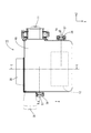
- the top view which shows the electrical connection box of embodiment The figure which abbreviate
- the electrical connection box 10 of Embodiment 1 will be described with reference to FIGS. 1 to 11.
- the electric connection box 10 of the present embodiment is mounted, for example, on a path between a power source such as a battery and a load including an on-vehicle electrical component or a motor in a vehicle such as an electric car or a hybrid car.
- a power source such as a battery
- a load including an on-vehicle electrical component or a motor in a vehicle such as an electric car or a hybrid car.
- the X direction will be described as the front
- the Y direction as the upper side
- the Z direction as the right side.
- the electric connection box 10 is connected to the terminal portion of the upper and lower two wire harnesses 11 connected to different systems of the vehicle, and as shown in FIG. 6, the lower case 20 and the upper fitted to the lower case 20 A case 40 is provided, and the circuit unit 12 (see FIG. 1) is accommodated inside.
- each wire harness 11 a plurality of electric wires are collectively surrounded by a synthetic resin corrugated tube.
- the plurality of electric wires are coated electric wires in which the periphery of a conductor portion made of, for example, a stranded wire formed by twisting metal wires or a single core wire is covered with an insulating layer.
- a corrugated tube is an exterior body in which convex portions and concave portions are alternately formed in a corrugated shape.
- the end portion of the wire harness 11 is attached and fixed between the lower case 20 and the upper case 40 on the right side.
- the circuit unit 12 has electronic components such as a coil, a capacitor, and a relay mounted on a circuit board.
- the lower case 20 and the upper case 40 are a plurality of circuit units covered with a synthetic resin inner case not shown. More than one can be accommodated.
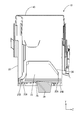
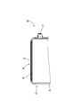
- the lower case 20 is made of insulating synthetic resin, and as shown in FIG. 7, it has a box-like shape whose upper side is opened in a rectangular shape, and a bottom surface 21 and a rectangular cylindrical circumferential wall 28 standing from the bottom surface 21. And a plurality of mounting portions 38 to be mounted to the vehicle.
- the bottom surface portion 21 includes a flat surface portion 22 extending along the horizontal direction and a sloped surface portion 23 extending obliquely upward from an end of the flat surface portion 22, as shown in FIGS.
- a drainage rib 24 protruding upward is provided annularly along the peripheral wall 28 across the slope portion 23 and the flat portion 22.
- the flat portion 22 is provided with drainage ports 25A and 25B connected to the outside. The water that has entered the outer side of the drainage rib 24 in the lower case 20 is led from the drainage channel on the outer side of the drainage rib 24 to the drainage port 25B and is drained.
- the flat portion 22 on the inner side of the drainage rib 24 is formed with a mountain portion 26 that slightly bulges upward to guide water to the drainage port 25A.
- the peripheral wall 28 has different heights depending on the position in the circumferential direction, and connects the front wall 29, the rear wall 34 facing the front wall 29, the front wall 29, and the rear wall 34. And a pair of side walls 35. Case locked portions 36 are provided on the pair of side walls 35, respectively.
- the case engagement portion 36 has an inward projecting engagement projection, and is engaged with the case engagement portion 57 of the upper case 40 to hold the lower case 20 and the upper case 40 in a fitted state. .
- the front wall 29 is shaped so as to have a recessed portion 29 ⁇ / b> A that is largely cut away at the upper portion, and a projecting portion 30 extending in the lateral direction in a substantially middle portion in the vertical direction. Is formed.
- the projecting portion 30 projects outward (forward) over substantially the entire width of the front wall 29, and as shown in FIG. 5, the thickness dimension on the outer surface (front) side of the front wall 29 is increased.
- the projecting portion 30 includes a stepped portion 30A which is erected in a step-like manner from the front surface at the lower end, and an inclined portion 30B which is inclined downward and which has a smaller projecting dimension.
- the upper part of the protrusion 30 is a plate-like portion 31 having a constant thickness. On the inner surface side of the tip end portion (upper end portion) of the plate-like portion 31, the notch portion 32 is notched in a tapered shape.
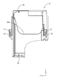
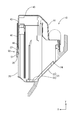
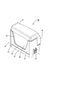
- the upper case 40 is made of insulating synthetic resin, and as shown in FIG. 10 and FIG. 11, the upper case 40 is a box having a rectangular opening at the lower side, and has a rectangular top plate portion 41 and a top plate portion 41. And a rectangular cylindrical peripheral wall 42 extending downward.
- the peripheral wall 42 is configured by connecting a front wall 43, a rear wall 44 (see FIG. 4) facing the front wall 43, and a pair of side walls 45 connecting the front wall 43 and the rear wall 44 in an angular tube shape. ing.
- a case locking portion 57 locked to the case locked portion 36 extends upward from the lower end of the side wall 45 so as to be flexible and deformable.
- the peripheral wall 42 includes a wall main body 46 disposed above the lower case 20 and an overlapping portion 47 overlapping the lower case 20.
- the overlapping portion 47 extends in the form of a square tube over the entire circumference in accordance with the peripheral wall 42 of the lower case 20, and as shown in FIG. And an outer wall 50.
- the inner wall 48 is a portion overlapping the inner side of the lower case 20 and is shorter than the length of the plate-like portion 31 in the lower case 20 in the vertical direction.
- the front end of the inner wall 48 is a notch 48A in which both the inside and the outside are tapered and notched.
- the inner wall 48 is connected to the outer wall 50 by a connecting portion 55.
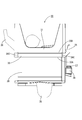
- the outer wall 50 is a portion overlapping the outer side of the lower case 20, and is provided to the first wall 51 provided at the lower end of the front wall 43 and in close contact with the outer surface of the lower case 20 And a second wall 52 facing each other with the clearance CL1 open.
- the first wall 51 is provided only on the front wall 43 of the peripheral wall 42, and extends in the form of a band over the entire width of the lower end of the front wall 43 (a part continuing below the second wall 52). .
- the second wall 52 is provided along the entire circumference of the peripheral wall 42, and the second wall 52 provided on the front wall 43 is provided inside the first wall 51 and in parallel with the first wall 51.
- the second wall 52 of the front wall 43 is shaped so as to have a recess 54 in which the boundary with the wall main body 46 is greatly recessed downward, and overlaps the plate-like portion 31 of the lower case 20. Is formed below the wall main body 46.
- the second wall 52 on the first wall 51 has a notch 53 in which the inner surface side of the lower end thereof is tapered. Further, on the inner surface side of the lower end of the first wall 51, a notch 51A cut in a tapered shape is formed.
- the distance between the inner wall 48 and the second wall 52 is between the plate 31 and the outer wall 50, and the inner wall 48 and the plate It is set as the space
- the clearances CL1 and CL2 have values such that the plate-like portion 31 can be easily inserted between the inner wall 48 and the second wall 52 according to the error of the assembling accuracy when the lower case 20 and the upper case 40 are assembled. It is set appropriately.
- the inner surface of the first wall portion 51 is in surface contact across the entire width of the outer surface of the projecting portion 30 of the lower case 20 to be in close contact. Further, the inner surface of the connecting portion 55 is in surface contact with the upper end of the plate-like portion 31 to be in a close contact state.
- the water droplet D that has reached the space S between the first wall 51 and the inclined portion 30B is inclined as shown in FIG. Move along the part 30B to the left and right. Then, when the water droplet D reaches the left and right end portions 30C of the protrusion 30, a gap (approximately the same size as the clearance CL1) is formed between the lower case 20 and the upper case 40. It is discharged under the case 40.
- the present embodiment since the first wall 51 of the upper case 40 is in close contact with the outer surface of the lower case 20, it is possible to suppress the entry of water into the case with a simple configuration.
- the plate-like portion 31 (upper end portion of the lower case 20) of the lower case 20 is inserted between the inner wall 48 and the second wall 52 with the clearances CL1 and CL2, an error in dimensional accuracy occurs.
- the plate-like portion 31 can be easily inserted between the second wall 52 and the inner wall 48, the lower case 20 and the upper case 40 can be easily assembled.
- the lower case 20 has a projecting portion 30 projecting toward the first wall 51 side, and the projecting portion 30 is formed with an inclined portion 30 B in which the projecting dimension on the upper side is reduced. According to this embodiment, even when an error in dimension occurs, the work of fitting the lower case 20 and the upper case 40 can be easily performed by the inclined portion 30B.
- a space S is formed between the inclined portion 30B and the outer wall 50 in which the water which has infiltrated moves along the inclined portion 30B.
- the lower case 20 and the upper case 40 are stacked with a gap, and the gap is provided up to a position reaching the lower end of the upper case 40. In this way, even if water intrudes into the inclined portion 30B, the infiltrated water can be moved along the inclined portion 30B and discharged downward from the gap between the upper case 40 and the lower case 20.
- the inner wall 48 and the outer wall 50 are connected by a connecting portion 55, and the connecting portion 55 is in close contact with the upper end of the lower case 20. In this way, even if water infiltrates from between the lower case 20 and the first wall portion 51 of the upper case 40, the upper end of the connecting portion 55 and the lower case 20 are in close contact with each other, and water in the case Infiltration can be regulated.
Abstract
An electric connection box 10 provided with a lower case 20 and an upper case 40 installed in the lower case 20, wherein: the upper case 40 is provided with an inner wall 48 facing the inner surface of the lower case 20, and an outer wall 50 facing the outer surface of the lower case 20; the outer wall 50 has a first wall part 51 in intimate contact with the outer surface of the lower case 20 and a second wall part 52 continuing above the first wall part 51; and the upper end part of the lower case 20 is inserted between the inner wall 48 and the second wall part 52 so as to leave clearances CL1, CL2.
Description
本発明は電気接続箱に関する。
The present invention relates to an electrical connection box.
車両に搭載される電気接続箱には、雨天走行時や洗車時において内部に水が浸入しないように防水構造が設けられている。特許文献1の電気接続箱は、本体ケースと、この本体ケースに取付けられるアッパカバーとが、二重壁構造になっており、アッパカバーの外壁と内壁との間に、本体ケースの外壁が挿入されている。アッパカバーの外壁先端、及び、本体ケースの外壁上端は、互いに当接する段付き形状となっており、アッパカバーの外壁と本体ケースの外壁との間の合わせ目の隙間を通って本体ケース内に浸入した水は、ロアカバーの水抜き孔から排水される。
The electric connection box mounted on the vehicle is provided with a waterproof structure so that water does not infiltrate into the interior during rainy weather travel or car wash. The electrical connection box of Patent Document 1 has a double-walled structure with a main case and an upper cover attached to the main case, and the outer wall of the main case is inserted between the outer wall and the inner wall of the upper cover. It is done. The outer wall tip of the upper cover and the upper end of the outer wall of the main case are in a stepped shape abutting each other, passing through the gap between the outer wall of the upper cover and the outer wall of the main case The entering water is drained from the drain hole of the lower cover.
ところで、特許文献1では、アッパカバーの外壁先端と本体ケースの外壁上端を段付き形状とすることで内部に水が浸入しにくくなっているが、アッパカバーの外壁と本体ケースの外壁との間の合わせ目に隙間が形成されているため、合わせ目の隙間から浸入した水が段付き形状の間を通り抜け、本体ケース内の内部に浸入する可能性がある。特許文献1では、本体ケースを二重壁とした排水構造が設けられており、本体ケース内の内部に浸入した水は、排水構造によって排水されるが、このような二重壁の排水構造を設けると、構成が複雑になるという問題がある。
By the way, in patent document 1, although it is difficult for water to infiltrate inside by making the outer wall tip of the upper cover and the outer wall upper end of the main body case into a stepped shape, between the outer wall of the upper cover and the outer wall of the main body case Since the gap is formed at the joint, water which has entered from the gap of the joint may pass between the stepped shapes and enter the inside of the main body case. In patent document 1, although the drainage structure which made the main body case the double wall is provided, although the water which entered inside the main body case is drained by the drainage structure, such a double wall drainage structure is used. If provided, there is a problem that the configuration becomes complicated.
本発明は上記のような事情に基づいて完成されたものであって、簡素な構成でケース内への水の浸入を抑制することが可能な電気接続箱を提供することを目的とする。
The present invention has been completed based on the above-described circumstances, and an object of the present invention is to provide an electrical connection box capable of suppressing the entry of water into a case with a simple configuration.
本発明は、ロアケースと、前記ロアケースに組付けられるアッパーケースとを備える電気接続箱であって、前記アッパーケースは、前記ロアケースの内面に対向する内壁と、前記ロアケースの外面に対向する外壁と、を備え、前記外壁は、前記ロアケースの外面に密着する第1壁部と、前記第1壁部の上方に連なる第2壁部とを有し、前記内壁と前記第2壁部との間には、前記ロアケースの上端部がクリアランスを有して挿通される。
The present invention is an electrical connection box including a lower case and an upper case assembled to the lower case, wherein the upper case is an inner wall facing the inner surface of the lower case, and an outer wall facing the outer surface of the lower case. The outer wall has a first wall in close contact with the outer surface of the lower case and a second wall extending above the first wall, and between the inner wall and the second wall The upper end of the lower case is inserted with clearance.
本発明は、ロアケースと、前記ロアケースに組付けられるアッパーケースとの間における電気接続箱の防水構造であって、前記アッパーケースは、前記ロアケースの内面に対向する内壁と、前記ロアケースの外面に対向する外壁と、を備え、前記外壁は、前記ロアケースの外面に密着する第1壁部と、前記第1壁部の上方に連なる第2壁部とを有し、前記内壁と前記第2壁部との間には、前記ロアケースの上端部がクリアランスを有して挿通される。
The present invention is a waterproof structure of an electrical connection box between a lower case and an upper case assembled to the lower case, wherein the upper case faces an inner wall facing an inner surface of the lower case and an outer surface of the lower case. An outer wall, the outer wall having a first wall in close contact with the outer surface of the lower case, and a second wall extending above the first wall, the inner wall and the second wall And the upper end portion of the lower case is inserted with clearance.
本構成によれば、第1壁部がロアケースの外面に密着するため、簡素な構成でケース内への水の浸入を抑制することが可能となる。一方、内壁と第2壁部との間には、ロアケースの上端部がクリアランスを有して挿通されるため、ロアケースとアッパーケースとの組付作業を容易に行うことができる。
According to this configuration, since the first wall closely contacts the outer surface of the lower case, it is possible to suppress the entry of water into the case with a simple configuration. On the other hand, since the upper end portion of the lower case is inserted between the inner wall and the second wall with a clearance, the lower case and the upper case can be easily assembled.
本発明の実施態様としては以下の態様が好ましい。
・前記ロアケースは、前記第1壁部側に突出する突出部を有し、前記突出部には、上方側の突出寸法が小さくなる傾斜部が形成されている。
本構成によれば、傾斜部によってロアケースとアッパーケースとを嵌合させる作業を容易に行うことができる。 The following aspects are preferable as an embodiment of this invention.
-The lower case has a projecting portion that protrudes toward the first wall side, and the projecting portion is formed with an inclined portion in which the projecting dimension on the upper side is reduced.
According to this configuration, it is possible to easily perform the work of fitting the lower case and the upper case by the inclined portion.
・前記傾斜部と前記外壁との間には浸入した水が前記傾斜部に沿って移動する空間が形成されており、前記傾斜部が延びる方向の端部では、前記ロアケースと前記アッパーケースとが隙間を有して重ねられており、この隙間は、前記アッパーケースの下端部に至る位置まで設けられている。
このようにすれば、傾斜部まで水が浸入したとしても、浸入した水を傾斜部に沿って移動させ、アッパーケースとロアケースとの間の隙間から下方に排出することができる。 -A space is formed between the sloped portion and the outer wall to move the infiltrated water along the sloped portion, and at the end portion in the direction in which the sloped portion extends, the lower case and the upper case It has a gap and is piled up, and this gap is provided to the position which reaches the lower end part of the above-mentioned upper case.
In this way, even if water intrudes into the sloped part, the water that has entered can be moved along the sloped part and discharged downward from the gap between the upper case and the lower case.
・前記内壁と前記外壁とは連結部で連結されており、前記連結部は、前記ロアケースの上端に密着している。
このようにすれば、仮にロアケースとアッパーケースの第1壁部との間から水が浸入した場合でも、連結部とロアケースの上端が密着することで、ケース内部への水の浸入を規制することができる。 The inner wall and the outer wall are connected by a connecting portion, and the connecting portion is in close contact with the upper end of the lower case.
In this way, even if water infiltrates from between the lower case and the first wall of the upper case, the upper end of the connecting part and the lower case closely adheres, thereby restricting the intrusion of water into the case. Can.
本発明によれば、簡素な構成でケース内への水の浸入を抑制することが可能となる。
According to the present invention, it is possible to suppress the entry of water into the case with a simple configuration.
<実施形態1>
実施形態1の電気接続箱10を図1ないし図11を参照しつつ説明する。
本実施形態の電気接続箱10は、例えば、電気自動車やハイブリッド自動車等の車両においてバッテリ等の電源と車載電装品やモータ等からなる負荷との間の経路に搭載される。以下では、X方向を前方、Y方向を上方、Z方向を右方として説明する。 First Embodiment
Theelectrical connection box 10 of Embodiment 1 will be described with reference to FIGS. 1 to 11.
Theelectric connection box 10 of the present embodiment is mounted, for example, on a path between a power source such as a battery and a load including an on-vehicle electrical component or a motor in a vehicle such as an electric car or a hybrid car. Hereinafter, the X direction will be described as the front, the Y direction as the upper side, and the Z direction as the right side.
実施形態1の電気接続箱10を図1ないし図11を参照しつつ説明する。
本実施形態の電気接続箱10は、例えば、電気自動車やハイブリッド自動車等の車両においてバッテリ等の電源と車載電装品やモータ等からなる負荷との間の経路に搭載される。以下では、X方向を前方、Y方向を上方、Z方向を右方として説明する。 First Embodiment
The
The
(電気接続箱10)
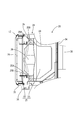
電気接続箱10は、車両の異なる系統に接続された上下2本のワイヤーハーネス11の端末部に接続されるものであり、図6に示すように、ロアケース20と、ロアケース20に嵌合するアッパーケース40とを備え、内部に回路部12(図1参照)が収容されている。各ワイヤーハーネス11は、複数の電線が合成樹脂製のコルゲートチューブで一括して包囲されている。複数の電線は、共に、例えば金属素線が撚り合わされてなる撚り線や単芯線等からなる導体部の周囲が絶縁層で被覆された被覆電線である。コルゲートチューブは、凸部と凹部とが交互に波形に形成された外装体である。ワイヤーハーネス11の端末部は、右側面におけるロアケース20とアッパーケース40との間に取付けられて固定される。 (Electrical connection box 10)
Theelectric connection box 10 is connected to the terminal portion of the upper and lower two wire harnesses 11 connected to different systems of the vehicle, and as shown in FIG. 6, the lower case 20 and the upper fitted to the lower case 20 A case 40 is provided, and the circuit unit 12 (see FIG. 1) is accommodated inside. In each wire harness 11, a plurality of electric wires are collectively surrounded by a synthetic resin corrugated tube. The plurality of electric wires are coated electric wires in which the periphery of a conductor portion made of, for example, a stranded wire formed by twisting metal wires or a single core wire is covered with an insulating layer. A corrugated tube is an exterior body in which convex portions and concave portions are alternately formed in a corrugated shape. The end portion of the wire harness 11 is attached and fixed between the lower case 20 and the upper case 40 on the right side.
電気接続箱10は、車両の異なる系統に接続された上下2本のワイヤーハーネス11の端末部に接続されるものであり、図6に示すように、ロアケース20と、ロアケース20に嵌合するアッパーケース40とを備え、内部に回路部12(図1参照)が収容されている。各ワイヤーハーネス11は、複数の電線が合成樹脂製のコルゲートチューブで一括して包囲されている。複数の電線は、共に、例えば金属素線が撚り合わされてなる撚り線や単芯線等からなる導体部の周囲が絶縁層で被覆された被覆電線である。コルゲートチューブは、凸部と凹部とが交互に波形に形成された外装体である。ワイヤーハーネス11の端末部は、右側面におけるロアケース20とアッパーケース40との間に取付けられて固定される。 (Electrical connection box 10)
The
回路部12は、回路基板にコイル、キャパシタ、リレー等の電子部品が実装されており、例えば、図示しない合成樹脂製のインナーケースで覆われた複数の回路ユニットとしてロアケース20とアッパーケース40の間に複数収容することができる。
The circuit unit 12 has electronic components such as a coil, a capacitor, and a relay mounted on a circuit board. For example, the lower case 20 and the upper case 40 are a plurality of circuit units covered with a synthetic resin inner case not shown. More than one can be accommodated.
(ロアケース20)
ロアケース20は、絶縁性の合成樹脂製であって、図7に示すように、上方側が長方形状に開口した箱型であり、底面部21と、底面部21から起立する角筒状の周壁28と、を備え、車両に取り付ける複数の取付部38が設けられている。 (Lower case 20)
Thelower case 20 is made of insulating synthetic resin, and as shown in FIG. 7, it has a box-like shape whose upper side is opened in a rectangular shape, and a bottom surface 21 and a rectangular cylindrical circumferential wall 28 standing from the bottom surface 21. And a plurality of mounting portions 38 to be mounted to the vehicle.
ロアケース20は、絶縁性の合成樹脂製であって、図7に示すように、上方側が長方形状に開口した箱型であり、底面部21と、底面部21から起立する角筒状の周壁28と、を備え、車両に取り付ける複数の取付部38が設けられている。 (Lower case 20)
The
底面部21は、図4,図8に示すように、水平方向に沿って延びる平面部22と、平面部22の端部から斜め上方側に延びる斜面部23とを備える。底面部21には、上方側に突出する排水リブ24が斜面部23と平面部22とに亘って周壁28に沿うように環状に設けられている。平面部22には、外部に連なる排水口25A,25Bが設けられている。ロアケース20内における排水リブ24の外側に浸入した水は、排水リブ24の外側の排水路から排水口25Bに導かれて排水される。排水リブ24の内側の平面部22には、わずかに上方に山形に張り出して水を排水口25Aに導く山部26が形成されている。
The bottom surface portion 21 includes a flat surface portion 22 extending along the horizontal direction and a sloped surface portion 23 extending obliquely upward from an end of the flat surface portion 22, as shown in FIGS. On the bottom surface portion 21, a drainage rib 24 protruding upward is provided annularly along the peripheral wall 28 across the slope portion 23 and the flat portion 22. The flat portion 22 is provided with drainage ports 25A and 25B connected to the outside. The water that has entered the outer side of the drainage rib 24 in the lower case 20 is led from the drainage channel on the outer side of the drainage rib 24 to the drainage port 25B and is drained. The flat portion 22 on the inner side of the drainage rib 24 is formed with a mountain portion 26 that slightly bulges upward to guide water to the drainage port 25A.
周壁28は、図7,図8に示すように、周方向の位置によって異なる高さとされ、前壁29と、前壁29に対向する後壁34と、前壁29と後壁34とを連結する一対の側壁35とを備えている。一対の側壁35には、それぞれケース被係止部36が設けられている。ケース被係止部36は、内方に突出する係止突部を有し、アッパーケース40のケース係止部57に係止されてロアケース20とアッパーケース40とが嵌合した状態に保持する。
As shown in FIGS. 7 and 8, the peripheral wall 28 has different heights depending on the position in the circumferential direction, and connects the front wall 29, the rear wall 34 facing the front wall 29, the front wall 29, and the rear wall 34. And a pair of side walls 35. Case locked portions 36 are provided on the pair of side walls 35, respectively. The case engagement portion 36 has an inward projecting engagement projection, and is engaged with the case engagement portion 57 of the upper case 40 to hold the lower case 20 and the upper case 40 in a fitted state. .
前壁29は、図7に示すように、上部が大きく切り欠かれて凹んだ凹み部29Aを有する形状とされており、上下方向の略中間部には、左右方向に帯状に延びる突出部30が形成されている。突出部30は、前壁29のほぼ全幅に亘って外方(前方)に突出しており、図5に示すように、前壁29について外面(前面)側の厚み寸法を大きくして形成されている。突出部30は、下端に前面から段差状に起立する段差部30Aを備え、上部に傾斜状に突出寸法が小さくなる傾斜部30Bを備える。突出部30の上方は、厚みが一定の板状の板状部31とされている。板状部31の先端部(上端部)の内面側は、テーパ状に切欠部32が切り欠かれている。
As shown in FIG. 7, the front wall 29 is shaped so as to have a recessed portion 29 </ b> A that is largely cut away at the upper portion, and a projecting portion 30 extending in the lateral direction in a substantially middle portion in the vertical direction. Is formed. The projecting portion 30 projects outward (forward) over substantially the entire width of the front wall 29, and as shown in FIG. 5, the thickness dimension on the outer surface (front) side of the front wall 29 is increased. There is. The projecting portion 30 includes a stepped portion 30A which is erected in a step-like manner from the front surface at the lower end, and an inclined portion 30B which is inclined downward and which has a smaller projecting dimension. The upper part of the protrusion 30 is a plate-like portion 31 having a constant thickness. On the inner surface side of the tip end portion (upper end portion) of the plate-like portion 31, the notch portion 32 is notched in a tapered shape.
(アッパーケース40)
アッパーケース40は、絶縁性の合成樹脂製であって、図10,図11に示すように、下方側が長方形状に開口した箱型であり、長方形状の天板部41と、天板部41の下方に延びる角筒状の周壁42とを備える。周壁42は、前壁43と、前壁43に対向する後壁44(図4参照)と、前壁43と後壁44とを連結する一対の側壁45とを角筒状に連ねて構成されている。一対の側壁45の外面には、図10に示すように、ケース被係止部36に係止するケース係止部57が側壁45の下端部から上方側に撓み変形可能に延びている。 (Upper case 40)
Theupper case 40 is made of insulating synthetic resin, and as shown in FIG. 10 and FIG. 11, the upper case 40 is a box having a rectangular opening at the lower side, and has a rectangular top plate portion 41 and a top plate portion 41. And a rectangular cylindrical peripheral wall 42 extending downward. The peripheral wall 42 is configured by connecting a front wall 43, a rear wall 44 (see FIG. 4) facing the front wall 43, and a pair of side walls 45 connecting the front wall 43 and the rear wall 44 in an angular tube shape. ing. On the outer surface of the pair of side walls 45, as shown in FIG. 10, a case locking portion 57 locked to the case locked portion 36 extends upward from the lower end of the side wall 45 so as to be flexible and deformable.
アッパーケース40は、絶縁性の合成樹脂製であって、図10,図11に示すように、下方側が長方形状に開口した箱型であり、長方形状の天板部41と、天板部41の下方に延びる角筒状の周壁42とを備える。周壁42は、前壁43と、前壁43に対向する後壁44(図4参照)と、前壁43と後壁44とを連結する一対の側壁45とを角筒状に連ねて構成されている。一対の側壁45の外面には、図10に示すように、ケース被係止部36に係止するケース係止部57が側壁45の下端部から上方側に撓み変形可能に延びている。 (Upper case 40)
The
周壁42は、ロアケース20の上方に配される壁本体46と、ロアケース20に重なる重なり部47とを備える。重なり部47は、ロアケース20の周壁42に応じて全周に亘って角筒状に延びており、図5に示すように、下方に突出する内壁48と、内壁48と間隔を空けて対向配置された外壁50とを備える。内壁48は、ロアケース20の内側に重なる部分であり、ロアケース20における板状部31の上下方向の長さよりも短くされている。内壁48の先端部は、内側及び外側の双方がテーパ状に切り欠かれた切欠部48Aとされている。内壁48は、外壁50と連結部55によって連結されている。
The peripheral wall 42 includes a wall main body 46 disposed above the lower case 20 and an overlapping portion 47 overlapping the lower case 20. The overlapping portion 47 extends in the form of a square tube over the entire circumference in accordance with the peripheral wall 42 of the lower case 20, and as shown in FIG. And an outer wall 50. The inner wall 48 is a portion overlapping the inner side of the lower case 20 and is shorter than the length of the plate-like portion 31 in the lower case 20 in the vertical direction. The front end of the inner wall 48 is a notch 48A in which both the inside and the outside are tapered and notched. The inner wall 48 is connected to the outer wall 50 by a connecting portion 55.
外壁50は、ロアケース20の外側に重なる部分であり、前壁43の下端部に設けられてロアケース20の外面に密着する第1壁部51と、ロアケース20における板状部31の外面に対してクリアランスCL1を空けて対向する第2壁部52とを備える。第1壁部51は、周壁42のうちの前壁43のみに設けられており、前壁43の下端部(第2壁部52の下に連なる部分)の全幅に亘って帯状に延びている。
The outer wall 50 is a portion overlapping the outer side of the lower case 20, and is provided to the first wall 51 provided at the lower end of the front wall 43 and in close contact with the outer surface of the lower case 20 And a second wall 52 facing each other with the clearance CL1 open. The first wall 51 is provided only on the front wall 43 of the peripheral wall 42, and extends in the form of a band over the entire width of the lower end of the front wall 43 (a part continuing below the second wall 52). .
第2壁部52は、周壁42の全周に亘って設けられ、前壁43に設けられる第2壁部52は、第1壁部51の内側かつ第1壁部51と平行に設けられている。前壁43の第2壁部52は、図10に示すように、壁本体46との境界が大きく下方に凹んだ凹み部54を有する形状とされており、ロアケース20の板状部31に重なるように壁本体46の下方に形成されている。図5に示すように、第1壁部51の上の第2壁部52は、その下端の内面側がテーパ状に切り欠かれた切欠部53とされている。また、第1壁部51の下端の内面側は、テーパ状に切り欠かれた切欠部51Aが形成されている。
The second wall 52 is provided along the entire circumference of the peripheral wall 42, and the second wall 52 provided on the front wall 43 is provided inside the first wall 51 and in parallel with the first wall 51. There is. As shown in FIG. 10, the second wall 52 of the front wall 43 is shaped so as to have a recess 54 in which the boundary with the wall main body 46 is greatly recessed downward, and overlaps the plate-like portion 31 of the lower case 20. Is formed below the wall main body 46. As shown in FIG. 5, the second wall 52 on the first wall 51 has a notch 53 in which the inner surface side of the lower end thereof is tapered. Further, on the inner surface side of the lower end of the first wall 51, a notch 51A cut in a tapered shape is formed.
内壁48と第2壁部52との間隔は、ロアケース20に対してアッパーケース40を正規位置に組付けた際に、板状部31と外壁50との間、及び、内壁48と板状部31との間にクリアランスCL1,CL2を有する間隔とされている。クリアランスCL1,CL2は、ロアケース20とアッパーケース40の組み付けの際に、組付精度の誤差に応じて内壁48と第2壁部52との間に板状部31を容易に挿入可能な値が適宜設定される。
When the upper case 40 is assembled to the lower case 20 at the regular position, the distance between the inner wall 48 and the second wall 52 is between the plate 31 and the outer wall 50, and the inner wall 48 and the plate It is set as the space | interval which has clearances CL1 and CL2 between 31 and. The clearances CL1 and CL2 have values such that the plate-like portion 31 can be easily inserted between the inner wall 48 and the second wall 52 according to the error of the assembling accuracy when the lower case 20 and the upper case 40 are assembled. It is set appropriately.
ロアケース20の上方側からアッパーケース40を下方に移動させて嵌合させると、第1壁部51の内面がロアケース20の突出部30の外面の全幅に亘って面接触して密着状態となる。また、連結部55の内面は、板状部31の上端に面接触して密着状態となる。これにより、洗車時等に前方から高圧の水が吹き付けられたとしても、ロアケース20とアッパーケース40とが密着状態となった部分によりケース内への水の浸入が規制される。また、第1壁部51と突出部30の間から水が浸入したとしても、第1壁部51と傾斜部30Bの間の空間Sに到達した水滴Dは、図6に示すように、傾斜部30Bを伝って左右に移動する。そして、水滴Dが突出部30の左右の端部30Cに至ると、ロアケース20とアッパーケース40との間には、隙間(クリアランスCL1とほぼ同じ寸法)が形成されているため、この隙間からアッパーケース40の下に排出される。
When the upper case 40 is moved downward and fitted from the upper side of the lower case 20, the inner surface of the first wall portion 51 is in surface contact across the entire width of the outer surface of the projecting portion 30 of the lower case 20 to be in close contact. Further, the inner surface of the connecting portion 55 is in surface contact with the upper end of the plate-like portion 31 to be in a close contact state. Thereby, even if high-pressure water is sprayed from the front during car washing etc., the part where the lower case 20 and the upper case 40 are in close contact with each other restricts the entry of water into the case. Further, even if water intrudes from between the first wall 51 and the projecting portion 30, the water droplet D that has reached the space S between the first wall 51 and the inclined portion 30B is inclined as shown in FIG. Move along the part 30B to the left and right. Then, when the water droplet D reaches the left and right end portions 30C of the protrusion 30, a gap (approximately the same size as the clearance CL1) is formed between the lower case 20 and the upper case 40. It is discharged under the case 40.
本実施形態によれば、以下の作用・効果を奏する。
本実施形態によれば、アッパーケース40の第1壁部51がロアケース20の外面に密着するため、簡素な構成でケース内への水の浸入を抑制することが可能となる。一方、内壁48と第2壁部52との間には、ロアケース20の板状部31(ロアケース20の上端部)がクリアランスCL1,CL2を有して挿通されるため、寸法精度の誤差が生じても、板状部31を第2壁部52と内壁48との間に容易に挿入することができるため、ロアケース20とアッパーケース40との組付作業を容易に行うことができる。 According to the present embodiment, the following effects can be obtained.
According to the present embodiment, since thefirst wall 51 of the upper case 40 is in close contact with the outer surface of the lower case 20, it is possible to suppress the entry of water into the case with a simple configuration. On the other hand, since the plate-like portion 31 (upper end portion of the lower case 20) of the lower case 20 is inserted between the inner wall 48 and the second wall 52 with the clearances CL1 and CL2, an error in dimensional accuracy occurs. However, since the plate-like portion 31 can be easily inserted between the second wall 52 and the inner wall 48, the lower case 20 and the upper case 40 can be easily assembled.
本実施形態によれば、アッパーケース40の第1壁部51がロアケース20の外面に密着するため、簡素な構成でケース内への水の浸入を抑制することが可能となる。一方、内壁48と第2壁部52との間には、ロアケース20の板状部31(ロアケース20の上端部)がクリアランスCL1,CL2を有して挿通されるため、寸法精度の誤差が生じても、板状部31を第2壁部52と内壁48との間に容易に挿入することができるため、ロアケース20とアッパーケース40との組付作業を容易に行うことができる。 According to the present embodiment, the following effects can be obtained.
According to the present embodiment, since the
また、ロアケース20は、第1壁部51側に突出する突出部30を有し、突出部30には、上方側の突出寸法が小さくなる傾斜部30Bが形成されている。
本実施形態によれば、寸法の誤差が生じた場合等でも傾斜部30Bによってロアケース20とアッパーケース40とを嵌合させる作業を容易に行うことができる。 Further, thelower case 20 has a projecting portion 30 projecting toward the first wall 51 side, and the projecting portion 30 is formed with an inclined portion 30 B in which the projecting dimension on the upper side is reduced.
According to this embodiment, even when an error in dimension occurs, the work of fitting thelower case 20 and the upper case 40 can be easily performed by the inclined portion 30B.
本実施形態によれば、寸法の誤差が生じた場合等でも傾斜部30Bによってロアケース20とアッパーケース40とを嵌合させる作業を容易に行うことができる。 Further, the
According to this embodiment, even when an error in dimension occurs, the work of fitting the
また、傾斜部30Bと外壁50との間には浸入した水が傾斜部30Bに沿って移動する空間Sが形成されており、傾斜部30Bが延びる方向の端部30Cでは、ロアケース20とアッパーケース40とが隙間を有して重ねられており、この隙間は、アッパーケース40の下端部に至る位置まで設けられている。
このようにすれば、傾斜部30Bまで水が浸入したとしても、浸入した水を傾斜部30Bに沿って移動させ、アッパーケース40とロアケース20との間の隙間から下方に排出することができる。 In addition, a space S is formed between theinclined portion 30B and the outer wall 50 in which the water which has infiltrated moves along the inclined portion 30B. At the end 30C in the direction in which the inclined portion 30B extends, the lower case 20 and the upper case 40 are stacked with a gap, and the gap is provided up to a position reaching the lower end of the upper case 40.
In this way, even if water intrudes into theinclined portion 30B, the infiltrated water can be moved along the inclined portion 30B and discharged downward from the gap between the upper case 40 and the lower case 20.
このようにすれば、傾斜部30Bまで水が浸入したとしても、浸入した水を傾斜部30Bに沿って移動させ、アッパーケース40とロアケース20との間の隙間から下方に排出することができる。 In addition, a space S is formed between the
In this way, even if water intrudes into the
また、内壁48と外壁50とは連結部55で連結されており、連結部55は、ロアケース20の上端に密着している。
このようにすれば、仮にロアケース20とアッパーケース40の第1壁部51との間から水が浸入した場合でも、連結部55とロアケース20の上端が密着することで、ケース内部への水の浸入を規制することができる。 Theinner wall 48 and the outer wall 50 are connected by a connecting portion 55, and the connecting portion 55 is in close contact with the upper end of the lower case 20.
In this way, even if water infiltrates from between thelower case 20 and the first wall portion 51 of the upper case 40, the upper end of the connecting portion 55 and the lower case 20 are in close contact with each other, and water in the case Infiltration can be regulated.
このようにすれば、仮にロアケース20とアッパーケース40の第1壁部51との間から水が浸入した場合でも、連結部55とロアケース20の上端が密着することで、ケース内部への水の浸入を規制することができる。 The
In this way, even if water infiltrates from between the
<他の実施形態>
本発明は上記記述及び図面によって説明した実施形態に限定されるものではなく、例えば次のような実施形態も本発明の技術的範囲に含まれる。
(1)上記実施形態では、ロアケース20の前壁29の上端は、アッパーケース40の連結部55に密着する構成としたが、これに限られず、ロアケース20の前壁29の上端と連結部55との間に隙間が形成されていてもよい。 Other Embodiments
The present invention is not limited to the embodiments described above with reference to the drawings. For example, the following embodiments are also included in the technical scope of the present invention.
(1) Although the upper end of thefront wall 29 of the lower case 20 is in close contact with the connecting portion 55 of the upper case 40 in the above embodiment, the present invention is not limited to this. The upper end of the front wall 29 of the lower case 20 and the connecting portion 55 And a gap may be formed between them.
本発明は上記記述及び図面によって説明した実施形態に限定されるものではなく、例えば次のような実施形態も本発明の技術的範囲に含まれる。
(1)上記実施形態では、ロアケース20の前壁29の上端は、アッパーケース40の連結部55に密着する構成としたが、これに限られず、ロアケース20の前壁29の上端と連結部55との間に隙間が形成されていてもよい。 Other Embodiments
The present invention is not limited to the embodiments described above with reference to the drawings. For example, the following embodiments are also included in the technical scope of the present invention.
(1) Although the upper end of the
(2)上記実施形態では、ロアケース20に対してアッパーケース40を正規位置に組付けた際に、内壁48と板状部31との間、及び、板状部31と外壁50との間にクリアランスCL1,CL2が生じることとしたが、これに限られず、内壁48と板状部31との間、及び、板状部31と外壁50との間の少なくとも一方にクリアランスが生じる構成としてもよい。
(2) In the above embodiment, when the upper case 40 is assembled to the lower case 20 at the normal position, the space between the inner wall 48 and the plate-like portion 31 and the space between the plate-like portion 31 and the outer wall 50 Although the clearances CL1 and CL2 are to be generated, the present invention is not limited thereto, and a clearance may be generated between at least one of the inner wall 48 and the plate portion 31 and between the plate portion 31 and the outer wall 50. .
10: 電気接続箱
20: ロアケース
24: 排水リブ
25A,25B: 排水口
28: 周壁
29: 前壁
30: 突出部
30B: 傾斜部
31: 板状部
40: アッパーケース
42: 周壁
43: 前壁
47: 重なり部
48: 内壁
50: 外壁
51: 第1壁部
52: 第2壁部
55: 連結部
CL1,CL2:クリアランス
S:空間 10: Electrical connection box 20: Lower case 24: Drain rib 25A, 25B: Drain 28: Peripheral wall 29: Front wall 30: Projection 30B: Slope 31: Plate 40: Upper case 42: Peripheral wall 43: Front wall 47 : Overlap portion 48: Inner wall 50: Outer wall 51: First wall portion 52: Second wall portion 55: Connecting portions CL1, CL2: Clearance S: Space
20: ロアケース
24: 排水リブ
25A,25B: 排水口
28: 周壁
29: 前壁
30: 突出部
30B: 傾斜部
31: 板状部
40: アッパーケース
42: 周壁
43: 前壁
47: 重なり部
48: 内壁
50: 外壁
51: 第1壁部
52: 第2壁部
55: 連結部
CL1,CL2:クリアランス
S:空間 10: Electrical connection box 20: Lower case 24:
Claims (5)
- ロアケースと、前記ロアケースに組付けられるアッパーケースとを備える電気接続箱であって、
前記アッパーケースは、前記ロアケースの内面に対向する内壁と、前記ロアケースの外面に対向する外壁と、を備え、
前記外壁は、前記ロアケースの外面に密着する第1壁部と、前記第1壁部の上方に連なる第2壁部とを有し、
前記内壁と前記第2壁部との間には、前記ロアケースの上端部がクリアランスを有して挿通される、電気接続箱。 An electrical connection box comprising a lower case and an upper case assembled to the lower case,
The upper case includes an inner wall facing the inner surface of the lower case, and an outer wall facing the outer surface of the lower case.
The outer wall has a first wall in close contact with the outer surface of the lower case, and a second wall extending above the first wall.
An electric connection box, wherein the upper end of the lower case is inserted between the inner wall and the second wall with a clearance. - 前記ロアケースは、前記第1壁部側に突出する突出部を有し、前記突出部には、上方側の突出寸法が小さくなる傾斜部が形成されている請求項1に記載の電気接続箱。 The electrical connection box according to claim 1, wherein the lower case has a protruding portion that protrudes toward the first wall side, and the protruding portion is formed with an inclined portion in which a protruding dimension on the upper side is reduced.
- 前記傾斜部と前記外壁との間には浸入した水が前記傾斜部に沿って移動する空間が形成されており、前記傾斜部が延びる方向の端部では、前記ロアケースと前記アッパーケースとが隙間を有して重ねられており、この隙間は、前記アッパーケースの下端部に至る位置まで設けられている請求項2に記載の電気接続箱。 A space is formed between the inclined portion and the outer wall to move the water which has entered along the inclined portion, and at the end in the direction in which the inclined portion extends, a gap is formed between the lower case and the upper case. The electrical connection box according to claim 2, wherein the gap is provided up to a position reaching the lower end portion of the upper case.
- 前記内壁と前記外壁とは連結部で連結されており、
前記連結部は、前記ロアケースの上端に密着している請求項1ないし請求項3のいずれか一項に記載の電気接続箱。 The inner wall and the outer wall are connected by a connection portion,
The electrical connection box according to any one of claims 1 to 3, wherein the connecting portion is in close contact with the upper end of the lower case. - ロアケースと、前記ロアケースに組付けられるアッパーケースとの間における電気接続箱の防水構造であって、
前記アッパーケースは、前記ロアケースの内面に対向する内壁と、前記ロアケースの外面に対向する外壁と、を備え、
前記外壁は、前記ロアケースの外面に密着する第1壁部と、前記第1壁部の上方に連なる第2壁部とを有し、
前記内壁と前記第2壁部との間には、前記ロアケースの上端部がクリアランスを有して挿通される、電気接続箱の防水構造。 A waterproof structure of an electrical connection box between a lower case and an upper case assembled to the lower case,
The upper case includes an inner wall facing the inner surface of the lower case, and an outer wall facing the outer surface of the lower case.
The outer wall has a first wall in close contact with the outer surface of the lower case, and a second wall extending above the first wall.
A waterproof structure of an electrical connection box, wherein an upper end portion of the lower case is inserted between the inner wall and the second wall portion with a clearance.
Priority Applications (2)
| Application Number | Priority Date | Filing Date | Title |
|---|---|---|---|
| CN201680028138.XA CN107615607B (en) | 2015-06-05 | 2016-05-16 | Electric connection box and waterproof structure thereof |
| US15/577,594 US10411449B2 (en) | 2015-06-05 | 2016-05-16 | Electrical junction box and waterproofing structure for electrical junction box |
Applications Claiming Priority (2)
| Application Number | Priority Date | Filing Date | Title |
|---|---|---|---|
| JP2015114637A JP6256414B2 (en) | 2015-06-05 | 2015-06-05 | Electrical junction box and waterproof structure of electrical junction box |
| JP2015-114637 | 2015-06-05 |
Publications (1)
| Publication Number | Publication Date |
|---|---|
| WO2016194588A1 true WO2016194588A1 (en) | 2016-12-08 |
Family
ID=57442001
Family Applications (1)
| Application Number | Title | Priority Date | Filing Date |
|---|---|---|---|
| PCT/JP2016/064418 WO2016194588A1 (en) | 2015-06-05 | 2016-05-16 | Electric connection box, and waterproofing structure for electric connection box |
Country Status (4)
| Country | Link |
|---|---|
| US (1) | US10411449B2 (en) |
| JP (1) | JP6256414B2 (en) |
| CN (1) | CN107615607B (en) |
| WO (1) | WO2016194588A1 (en) |
Cited By (1)
| Publication number | Priority date | Publication date | Assignee | Title |
|---|---|---|---|---|
| EP3578419A1 (en) * | 2018-06-07 | 2019-12-11 | Yazaki Corporation | Lock structure, electric connection box and wire harness |
Families Citing this family (4)
| Publication number | Priority date | Publication date | Assignee | Title |
|---|---|---|---|---|
| JP2019210027A (en) * | 2018-06-07 | 2019-12-12 | 矢崎総業株式会社 | Liquid-proof structure for fitting body, electrical connection box and wire harness |
| JP7167846B2 (en) * | 2019-05-15 | 2022-11-09 | 株式会社オートネットワーク技術研究所 | electric junction box |
| JP7116027B2 (en) * | 2019-09-13 | 2022-08-09 | 矢崎総業株式会社 | Electrical Junction Box and Wire Harness |
| JP7139540B1 (en) | 2022-03-30 | 2022-09-20 | Sdpグローバル株式会社 | Method for producing water absorbent resin composition, water absorbent resin composition, absorbent body using the same, and absorbent article |
Citations (4)
| Publication number | Priority date | Publication date | Assignee | Title |
|---|---|---|---|---|
| JPH07298451A (en) * | 1994-04-22 | 1995-11-10 | Sumitomo Wiring Syst Ltd | Electric connection box |
| JP2003319530A (en) * | 2002-04-23 | 2003-11-07 | Yazaki Corp | Electric junction box |
| JP2013005675A (en) * | 2011-06-21 | 2013-01-07 | Yazaki Corp | Box |
| JP2014236654A (en) * | 2013-06-05 | 2014-12-15 | 矢崎総業株式会社 | Electric connection box |
Family Cites Families (8)
| Publication number | Priority date | Publication date | Assignee | Title |
|---|---|---|---|---|
| JP2575979Y2 (en) * | 1993-07-01 | 1998-07-02 | 住友電装株式会社 | Sled correction structure for electrical junction box |
| JP2891324B2 (en) * | 1994-05-25 | 1999-05-17 | 矢崎総業株式会社 | Waterproof seal structure of electrical junction box |
| JP4013673B2 (en) * | 2002-07-09 | 2007-11-28 | 住友電装株式会社 | Drainage structure of electrical component storage box |
| JP5101891B2 (en) * | 2007-01-10 | 2012-12-19 | 矢崎総業株式会社 | Electrical junction box |
| JP5341626B2 (en) * | 2009-06-11 | 2013-11-13 | 矢崎総業株式会社 | Waterproof box |
| JP5944256B2 (en) | 2012-07-25 | 2016-07-05 | 矢崎総業株式会社 | Waterproof box |
| GB2540600B (en) * | 2015-07-22 | 2019-10-02 | Electrix International Ltd | An electrical component enclosure for recessing into and fixing to a surface |
| JP2018042356A (en) * | 2016-09-06 | 2018-03-15 | 住友電装株式会社 | Electric connection box |
-
2015
- 2015-06-05 JP JP2015114637A patent/JP6256414B2/en active Active
-
2016
- 2016-05-16 US US15/577,594 patent/US10411449B2/en active Active
- 2016-05-16 CN CN201680028138.XA patent/CN107615607B/en active Active
- 2016-05-16 WO PCT/JP2016/064418 patent/WO2016194588A1/en active Application Filing
Patent Citations (4)
| Publication number | Priority date | Publication date | Assignee | Title |
|---|---|---|---|---|
| JPH07298451A (en) * | 1994-04-22 | 1995-11-10 | Sumitomo Wiring Syst Ltd | Electric connection box |
| JP2003319530A (en) * | 2002-04-23 | 2003-11-07 | Yazaki Corp | Electric junction box |
| JP2013005675A (en) * | 2011-06-21 | 2013-01-07 | Yazaki Corp | Box |
| JP2014236654A (en) * | 2013-06-05 | 2014-12-15 | 矢崎総業株式会社 | Electric connection box |
Cited By (1)
| Publication number | Priority date | Publication date | Assignee | Title |
|---|---|---|---|---|
| EP3578419A1 (en) * | 2018-06-07 | 2019-12-11 | Yazaki Corporation | Lock structure, electric connection box and wire harness |
Also Published As
| Publication number | Publication date |
|---|---|
| US20180337522A1 (en) | 2018-11-22 |
| US10411449B2 (en) | 2019-09-10 |
| CN107615607B (en) | 2020-06-16 |
| JP6256414B2 (en) | 2018-01-10 |
| JP2017005791A (en) | 2017-01-05 |
| CN107615607A (en) | 2018-01-19 |
Similar Documents
| Publication | Publication Date | Title |
|---|---|---|
| WO2016194588A1 (en) | Electric connection box, and waterproofing structure for electric connection box | |
| US9431806B2 (en) | Waterproof box and electric junction box equipped with same | |
| JP5173596B2 (en) | Electrical junction box | |
| US10305267B2 (en) | Electrical connection box and wire harness | |
| JP6164571B2 (en) | Electrical junction box | |
| US10326262B2 (en) | Electrical connection box | |
| US9124079B2 (en) | Electric junction box | |
| US9331462B2 (en) | Junction box | |
| US9391437B2 (en) | Electrical junction box | |
| US6971888B2 (en) | Waterproof structure of electric junction box | |
| US9591774B2 (en) | Electrical junction box | |
| JP2009124874A (en) | Electrical junction box | |
| US20190067924A1 (en) | Electrical junction box | |
| JP2014103797A (en) | Electric connection box | |
| JP6230187B2 (en) | Electrical junction box | |
| JP5086112B2 (en) | Waterproof case | |
| JP5394302B2 (en) | Electrical junction box | |
| JP2010200431A (en) | Electrical junction box | |
| US10462914B2 (en) | Cover structure and electric connection box | |
| JP2010041778A (en) | Housing for electric apparatus for vehicle | |
| JP6931315B2 (en) | Electrical junction box and wire harness | |
| JP6797705B2 (en) | Electrical junction box and wire harness | |
| JP7115938B2 (en) | Electrical Junction Box and Wire Harness | |
| JP6996986B2 (en) | Housing and electrical junction box | |
| JP2007081262A (en) | Cabinet having electric wire drawer section |
Legal Events
| Date | Code | Title | Description |
|---|---|---|---|
| 121 | Ep: the epo has been informed by wipo that ep was designated in this application |
Ref document number: 16803024 Country of ref document: EP Kind code of ref document: A1 |
|
| WWE | Wipo information: entry into national phase |
Ref document number: 15577594 Country of ref document: US |
|
| NENP | Non-entry into the national phase |
Ref country code: DE |
|
| 122 | Ep: pct application non-entry in european phase |
Ref document number: 16803024 Country of ref document: EP Kind code of ref document: A1 |