WO2016194308A1 - Electronic device - Google Patents
Electronic device Download PDFInfo
- Publication number
- WO2016194308A1 WO2016194308A1 PCT/JP2016/002307 JP2016002307W WO2016194308A1 WO 2016194308 A1 WO2016194308 A1 WO 2016194308A1 JP 2016002307 W JP2016002307 W JP 2016002307W WO 2016194308 A1 WO2016194308 A1 WO 2016194308A1
- Authority
- WO
- WIPO (PCT)
- Prior art keywords
- electronic device
- subject
- pulse wave
- unit
- sensor
- Prior art date
Links
Images


Classifications
-
- A—HUMAN NECESSITIES
- A61—MEDICAL OR VETERINARY SCIENCE; HYGIENE
- A61B—DIAGNOSIS; SURGERY; IDENTIFICATION
- A61B5/00—Measuring for diagnostic purposes; Identification of persons
- A61B5/02—Detecting, measuring or recording pulse, heart rate, blood pressure or blood flow; Combined pulse/heart-rate/blood pressure determination; Evaluating a cardiovascular condition not otherwise provided for, e.g. using combinations of techniques provided for in this group with electrocardiography or electroauscultation; Heart catheters for measuring blood pressure
- A61B5/024—Detecting, measuring or recording pulse rate or heart rate
- A61B5/02444—Details of sensor
-
- A—HUMAN NECESSITIES
- A61—MEDICAL OR VETERINARY SCIENCE; HYGIENE
- A61B—DIAGNOSIS; SURGERY; IDENTIFICATION
- A61B5/00—Measuring for diagnostic purposes; Identification of persons
- A61B5/0002—Remote monitoring of patients using telemetry, e.g. transmission of vital signals via a communication network
- A61B5/0004—Remote monitoring of patients using telemetry, e.g. transmission of vital signals via a communication network characterised by the type of physiological signal transmitted
-
- A—HUMAN NECESSITIES
- A61—MEDICAL OR VETERINARY SCIENCE; HYGIENE
- A61B—DIAGNOSIS; SURGERY; IDENTIFICATION
- A61B5/00—Measuring for diagnostic purposes; Identification of persons
- A61B5/02—Detecting, measuring or recording pulse, heart rate, blood pressure or blood flow; Combined pulse/heart-rate/blood pressure determination; Evaluating a cardiovascular condition not otherwise provided for, e.g. using combinations of techniques provided for in this group with electrocardiography or electroauscultation; Heart catheters for measuring blood pressure
- A61B5/02007—Evaluating blood vessel condition, e.g. elasticity, compliance
-
- A—HUMAN NECESSITIES
- A61—MEDICAL OR VETERINARY SCIENCE; HYGIENE
- A61B—DIAGNOSIS; SURGERY; IDENTIFICATION
- A61B5/00—Measuring for diagnostic purposes; Identification of persons
- A61B5/02—Detecting, measuring or recording pulse, heart rate, blood pressure or blood flow; Combined pulse/heart-rate/blood pressure determination; Evaluating a cardiovascular condition not otherwise provided for, e.g. using combinations of techniques provided for in this group with electrocardiography or electroauscultation; Heart catheters for measuring blood pressure
- A61B5/02028—Determining haemodynamic parameters not otherwise provided for, e.g. cardiac contractility or left ventricular ejection fraction
- A61B5/02035—Determining blood viscosity
-
- A—HUMAN NECESSITIES
- A61—MEDICAL OR VETERINARY SCIENCE; HYGIENE
- A61B—DIAGNOSIS; SURGERY; IDENTIFICATION
- A61B5/00—Measuring for diagnostic purposes; Identification of persons
- A61B5/02—Detecting, measuring or recording pulse, heart rate, blood pressure or blood flow; Combined pulse/heart-rate/blood pressure determination; Evaluating a cardiovascular condition not otherwise provided for, e.g. using combinations of techniques provided for in this group with electrocardiography or electroauscultation; Heart catheters for measuring blood pressure
- A61B5/026—Measuring blood flow
- A61B5/0285—Measuring or recording phase velocity of blood waves
-
- A—HUMAN NECESSITIES
- A61—MEDICAL OR VETERINARY SCIENCE; HYGIENE
- A61B—DIAGNOSIS; SURGERY; IDENTIFICATION
- A61B5/00—Measuring for diagnostic purposes; Identification of persons
- A61B5/02—Detecting, measuring or recording pulse, heart rate, blood pressure or blood flow; Combined pulse/heart-rate/blood pressure determination; Evaluating a cardiovascular condition not otherwise provided for, e.g. using combinations of techniques provided for in this group with electrocardiography or electroauscultation; Heart catheters for measuring blood pressure
- A61B5/026—Measuring blood flow
- A61B5/0295—Measuring blood flow using plethysmography, i.e. measuring the variations in the volume of a body part as modified by the circulation of blood therethrough, e.g. impedance plethysmography
-
- A—HUMAN NECESSITIES
- A61—MEDICAL OR VETERINARY SCIENCE; HYGIENE
- A61B—DIAGNOSIS; SURGERY; IDENTIFICATION
- A61B5/00—Measuring for diagnostic purposes; Identification of persons
- A61B5/103—Detecting, measuring or recording devices for testing the shape, pattern, colour, size or movement of the body or parts thereof, for diagnostic purposes
- A61B5/11—Measuring movement of the entire body or parts thereof, e.g. head or hand tremor, mobility of a limb
- A61B5/1121—Determining geometric values, e.g. centre of rotation or angular range of movement
-
- A—HUMAN NECESSITIES
- A61—MEDICAL OR VETERINARY SCIENCE; HYGIENE
- A61B—DIAGNOSIS; SURGERY; IDENTIFICATION
- A61B5/00—Measuring for diagnostic purposes; Identification of persons
- A61B5/145—Measuring characteristics of blood in vivo, e.g. gas concentration, pH value; Measuring characteristics of body fluids or tissues, e.g. interstitial fluid, cerebral tissue
- A61B5/14532—Measuring characteristics of blood in vivo, e.g. gas concentration, pH value; Measuring characteristics of body fluids or tissues, e.g. interstitial fluid, cerebral tissue for measuring glucose, e.g. by tissue impedance measurement
-
- A—HUMAN NECESSITIES
- A61—MEDICAL OR VETERINARY SCIENCE; HYGIENE
- A61B—DIAGNOSIS; SURGERY; IDENTIFICATION
- A61B5/00—Measuring for diagnostic purposes; Identification of persons
- A61B5/145—Measuring characteristics of blood in vivo, e.g. gas concentration, pH value; Measuring characteristics of body fluids or tissues, e.g. interstitial fluid, cerebral tissue
- A61B5/14546—Measuring characteristics of blood in vivo, e.g. gas concentration, pH value; Measuring characteristics of body fluids or tissues, e.g. interstitial fluid, cerebral tissue for measuring analytes not otherwise provided for, e.g. ions, cytochromes
-
- A—HUMAN NECESSITIES
- A61—MEDICAL OR VETERINARY SCIENCE; HYGIENE
- A61B—DIAGNOSIS; SURGERY; IDENTIFICATION
- A61B5/00—Measuring for diagnostic purposes; Identification of persons
- A61B5/48—Other medical applications
- A61B5/4866—Evaluating metabolism
-
- A—HUMAN NECESSITIES
- A61—MEDICAL OR VETERINARY SCIENCE; HYGIENE
- A61B—DIAGNOSIS; SURGERY; IDENTIFICATION
- A61B5/00—Measuring for diagnostic purposes; Identification of persons
- A61B5/68—Arrangements of detecting, measuring or recording means, e.g. sensors, in relation to patient
- A61B5/6801—Arrangements of detecting, measuring or recording means, e.g. sensors, in relation to patient specially adapted to be attached to or worn on the body surface
- A61B5/6802—Sensor mounted on worn items
- A61B5/681—Wristwatch-type devices
-
- A—HUMAN NECESSITIES
- A61—MEDICAL OR VETERINARY SCIENCE; HYGIENE
- A61B—DIAGNOSIS; SURGERY; IDENTIFICATION
- A61B5/00—Measuring for diagnostic purposes; Identification of persons
- A61B5/68—Arrangements of detecting, measuring or recording means, e.g. sensors, in relation to patient
- A61B5/6801—Arrangements of detecting, measuring or recording means, e.g. sensors, in relation to patient specially adapted to be attached to or worn on the body surface
- A61B5/6813—Specially adapted to be attached to a specific body part
- A61B5/6824—Arm or wrist
-
- A—HUMAN NECESSITIES
- A61—MEDICAL OR VETERINARY SCIENCE; HYGIENE
- A61B—DIAGNOSIS; SURGERY; IDENTIFICATION
- A61B5/00—Measuring for diagnostic purposes; Identification of persons
- A61B5/68—Arrangements of detecting, measuring or recording means, e.g. sensors, in relation to patient
- A61B5/6801—Arrangements of detecting, measuring or recording means, e.g. sensors, in relation to patient specially adapted to be attached to or worn on the body surface
- A61B5/683—Means for maintaining contact with the body
- A61B5/6831—Straps, bands or harnesses
-
- A—HUMAN NECESSITIES
- A61—MEDICAL OR VETERINARY SCIENCE; HYGIENE
- A61B—DIAGNOSIS; SURGERY; IDENTIFICATION
- A61B5/00—Measuring for diagnostic purposes; Identification of persons
- A61B5/68—Arrangements of detecting, measuring or recording means, e.g. sensors, in relation to patient
- A61B5/6801—Arrangements of detecting, measuring or recording means, e.g. sensors, in relation to patient specially adapted to be attached to or worn on the body surface
- A61B5/6843—Monitoring or controlling sensor contact pressure
-
- A—HUMAN NECESSITIES
- A61—MEDICAL OR VETERINARY SCIENCE; HYGIENE
- A61B—DIAGNOSIS; SURGERY; IDENTIFICATION
- A61B5/00—Measuring for diagnostic purposes; Identification of persons
- A61B5/72—Signal processing specially adapted for physiological signals or for diagnostic purposes
- A61B5/7271—Specific aspects of physiological measurement analysis
- A61B5/7278—Artificial waveform generation or derivation, e.g. synthesising signals from measured signals
-
- G—PHYSICS
- G16—INFORMATION AND COMMUNICATION TECHNOLOGY [ICT] SPECIALLY ADAPTED FOR SPECIFIC APPLICATION FIELDS
- G16H—HEALTHCARE INFORMATICS, i.e. INFORMATION AND COMMUNICATION TECHNOLOGY [ICT] SPECIALLY ADAPTED FOR THE HANDLING OR PROCESSING OF MEDICAL OR HEALTHCARE DATA
- G16H40/00—ICT specially adapted for the management or administration of healthcare resources or facilities; ICT specially adapted for the management or operation of medical equipment or devices
- G16H40/60—ICT specially adapted for the management or administration of healthcare resources or facilities; ICT specially adapted for the management or operation of medical equipment or devices for the operation of medical equipment or devices
- G16H40/63—ICT specially adapted for the management or administration of healthcare resources or facilities; ICT specially adapted for the management or operation of medical equipment or devices for the operation of medical equipment or devices for local operation
-
- G—PHYSICS
- G16—INFORMATION AND COMMUNICATION TECHNOLOGY [ICT] SPECIALLY ADAPTED FOR SPECIFIC APPLICATION FIELDS
- G16H—HEALTHCARE INFORMATICS, i.e. INFORMATION AND COMMUNICATION TECHNOLOGY [ICT] SPECIALLY ADAPTED FOR THE HANDLING OR PROCESSING OF MEDICAL OR HEALTHCARE DATA
- G16H50/00—ICT specially adapted for medical diagnosis, medical simulation or medical data mining; ICT specially adapted for detecting, monitoring or modelling epidemics or pandemics
- G16H50/20—ICT specially adapted for medical diagnosis, medical simulation or medical data mining; ICT specially adapted for detecting, monitoring or modelling epidemics or pandemics for computer-aided diagnosis, e.g. based on medical expert systems
-
- G—PHYSICS
- G16—INFORMATION AND COMMUNICATION TECHNOLOGY [ICT] SPECIALLY ADAPTED FOR SPECIFIC APPLICATION FIELDS
- G16H—HEALTHCARE INFORMATICS, i.e. INFORMATION AND COMMUNICATION TECHNOLOGY [ICT] SPECIALLY ADAPTED FOR THE HANDLING OR PROCESSING OF MEDICAL OR HEALTHCARE DATA
- G16H50/00—ICT specially adapted for medical diagnosis, medical simulation or medical data mining; ICT specially adapted for detecting, monitoring or modelling epidemics or pandemics
- G16H50/30—ICT specially adapted for medical diagnosis, medical simulation or medical data mining; ICT specially adapted for detecting, monitoring or modelling epidemics or pandemics for calculating health indices; for individual health risk assessment
-
- A—HUMAN NECESSITIES
- A61—MEDICAL OR VETERINARY SCIENCE; HYGIENE
- A61B—DIAGNOSIS; SURGERY; IDENTIFICATION
- A61B2560/00—Constructional details of operational features of apparatus; Accessories for medical measuring apparatus
- A61B2560/02—Operational features
- A61B2560/0242—Operational features adapted to measure environmental factors, e.g. temperature, pollution
- A61B2560/0247—Operational features adapted to measure environmental factors, e.g. temperature, pollution for compensation or correction of the measured physiological value
- A61B2560/0252—Operational features adapted to measure environmental factors, e.g. temperature, pollution for compensation or correction of the measured physiological value using ambient temperature
-
- A—HUMAN NECESSITIES
- A61—MEDICAL OR VETERINARY SCIENCE; HYGIENE
- A61B—DIAGNOSIS; SURGERY; IDENTIFICATION
- A61B2560/00—Constructional details of operational features of apparatus; Accessories for medical measuring apparatus
- A61B2560/04—Constructional details of apparatus
- A61B2560/0462—Apparatus with built-in sensors
-
- A—HUMAN NECESSITIES
- A61—MEDICAL OR VETERINARY SCIENCE; HYGIENE
- A61B—DIAGNOSIS; SURGERY; IDENTIFICATION
- A61B5/00—Measuring for diagnostic purposes; Identification of persons
- A61B5/0002—Remote monitoring of patients using telemetry, e.g. transmission of vital signals via a communication network
- A61B5/0015—Remote monitoring of patients using telemetry, e.g. transmission of vital signals via a communication network characterised by features of the telemetry system
- A61B5/0022—Monitoring a patient using a global network, e.g. telephone networks, internet
-
- A—HUMAN NECESSITIES
- A61—MEDICAL OR VETERINARY SCIENCE; HYGIENE
- A61B—DIAGNOSIS; SURGERY; IDENTIFICATION
- A61B5/00—Measuring for diagnostic purposes; Identification of persons
- A61B5/02—Detecting, measuring or recording pulse, heart rate, blood pressure or blood flow; Combined pulse/heart-rate/blood pressure determination; Evaluating a cardiovascular condition not otherwise provided for, e.g. using combinations of techniques provided for in this group with electrocardiography or electroauscultation; Heart catheters for measuring blood pressure
- A61B5/024—Detecting, measuring or recording pulse rate or heart rate
- A61B5/02438—Detecting, measuring or recording pulse rate or heart rate with portable devices, e.g. worn by the patient
Definitions
- the present invention relates to an electronic device that estimates the health status of a subject from measured biological information.
- Patent Document 1 describes an electronic device that measures the pulse of a subject when the subject wears the wrist.
- Patent Document 1 since blood collection is painful, it is difficult to estimate one's own health status on a daily basis.
- the electronic device described in Patent Document 1 only measures a pulse, and cannot estimate the health condition of the subject other than the pulse.
- An object of the present invention made in view of such circumstances is to provide an electronic device that can easily and non-invasively estimate the health condition of a subject.
- an electronic device is A wearing part to be worn by the subject;
- a sensor unit including a sensor for detecting the pulse wave of the subject,
- the sensor part has a displacement part that contacts the subject site of the subject when the wearing part is attached to the subject and is displaced according to the pulse wave of the subject.
- FIG. 1 It is a schematic diagram which shows schematic structure of the electronic device which concerns on 1st Embodiment of this invention. It is sectional drawing which shows schematic structure of the main-body part of FIG. It is a figure which shows an example of the use condition of the electronic device of FIG. It is a functional block diagram which shows schematic structure of the electronic device of FIG. It is a figure which shows an example of the pulse wave acquired by the sensor part. It is a figure which shows the time fluctuation
- FIG. 1 is a schematic diagram showing a schematic configuration of an electronic apparatus according to the first embodiment of the present invention.
- the electronic device 100 includes a mounting unit 110 and a measurement unit 120.
- FIG. 1 is a diagram in which the electronic device 100 is observed from the back surface 120a in contact with the test site.
- the electronic device 100 measures the biological information of the subject while the subject is wearing the electronic device 100.
- the biological information measured by the electronic device 100 is a pulse wave of the subject that can be measured by the measurement unit 120.
- electronic device 100 will be described below assuming that it is attached to the wrist of a subject and acquires a pulse wave.
- the mounting portion 110 is a straight and elongated band.
- the measurement of the pulse wave is performed, for example, in a state where the subject wraps the mounting unit 110 of the electronic device 100 around the wrist. Specifically, the subject wraps the mounting unit 110 around the wrist so that the back surface 120a of the measuring unit 120 is in contact with the test site, and measures the pulse wave.
- the electronic device 100 measures the pulse wave of blood flowing through the ulnar artery or radial artery at the wrist of the subject.
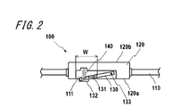
- FIG. 2 is a cross-sectional view showing a schematic configuration of the measurement unit 120 of FIG. In FIG. 2, the mounting unit 110 around the measurement unit 120 is also illustrated along with the measurement unit 120.
- the measuring unit 120 has a back surface 120a that contacts the wrist of the subject when worn, and a surface 120b opposite to the back surface 120a.
- the measurement unit 120 has an opening 111 on the back surface 120a side.
- the sensor unit 130 is supported by the measurement unit 120 with one end protruding from the opening 111 toward the back surface 120a in a state where the elastic body 140 is not pressed.
- One end of the sensor unit 130 is provided with a pulse applying unit 132.
- One end of the sensor unit 130 can be displaced in a direction substantially perpendicular to the plane of the back surface 120a.
- the other end of the sensor unit 130 is supported by the measurement unit 120 by the support unit 133 so that one end of the sensor unit 130 can be displaced.
- the elastic body 140 is, for example, a spring.
- the elastic body 140 is not limited to a spring, and may be any other elastic body such as a resin or a sponge.
- the measurement unit 120 may include a control unit, a storage unit, a communication unit, a power supply unit, a notification unit, a circuit that operates these, a cable to be connected, and the like.
- the sensor unit 130 includes an angular velocity sensor 131 that detects the displacement of the sensor unit 130.
- the angular velocity sensor 131 only needs to detect the angular displacement of the sensor unit 130.
- the sensor included in the sensor unit 130 is not limited to the angular velocity sensor 131, and may be, for example, an acceleration sensor, an angle sensor, other motion sensors, or a plurality of these sensors.
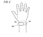
- FIG. 3 is a diagram illustrating an example of a usage state of the electronic device 100 by the subject.
- the subject wraps the electronic device 100 around the wrist and uses it.
- the electronic device 100 is mounted with the back surface 120a of the measurement unit 120 in contact with the test site.
- the measurement part 120 can adjust the position so that the pulse applying part 132 contacts the position where the ulnar artery or radial artery is present.
- one end of the sensor unit 130 is in contact with the skin on the radial artery, which is the artery on the thumb side of the left hand of the subject.
- One end of the sensor unit 130 is in contact with the skin on the radial artery of the subject due to the elastic force of the elastic body 140 disposed between the measurement unit 120 and the sensor unit 130.
- the sensor unit 130 is displaced according to the movement of the radial artery of the subject, that is, pulsation.
- the angular velocity sensor 131 acquires a pulse wave by detecting the displacement of the sensor unit 130.
- the pulse wave is obtained by capturing a change in the volume of the blood vessel caused by the inflow of blood as a waveform from the body surface.
- the sensor unit 130 is in a state in which one end protrudes from the opening 111 in a state where the elastic body 140 is not pressed.
- the elastic body 140 expands and contracts according to the pulsation, and one end of the sensor unit 130 Is displaced.
- an elastic body having an appropriate elastic modulus is used so as not to disturb the pulsation and to expand and contract in accordance with the pulsation.
- the opening width W of the opening 111 is sufficiently larger than the blood vessel diameter, in this embodiment, the radial artery diameter.
- FIG. 3 shows an example in which the electronic device 100 is worn on the wrist and a pulse wave in the radial artery is acquired, but the present invention is not limited to this.
- the electronic device 100 may acquire a pulse wave of blood flowing through the carotid artery at the subject's neck.
- the subject may measure the pulse wave by lightly pressing the pulse applying portion 132 against the position of the carotid artery.
- the subject may be mounted by wrapping the mounting portion 110 around the neck so that the pulse-applying portion 132 is positioned at the carotid artery.
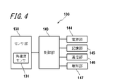
- FIG. 4 is a functional block diagram illustrating a schematic configuration of the electronic device 100.
- the electronic device 100 includes a sensor unit 130, a control unit 143, a power supply unit 144, a storage unit 145, a communication unit 146, and a notification unit 147.
- the control unit 143, the power supply unit 144, the storage unit 145, the communication unit 146, and the notification unit 147 are included in the measurement unit 120 or the mounting unit 110.
- the sensor unit 130 includes an angular velocity sensor 131 and detects a pulsation from a region to be examined to acquire a pulse wave.
- the control unit 143 is a processor that controls and manages the entire electronic device 100 including each functional block of the electronic device 100.
- the control unit 143 is a processor that calculates an index based on the propagation phenomenon of the pulse wave from the acquired pulse wave.
- the control unit 143 includes a processor such as a CPU (Central (Processing Unit) that executes a program that defines a control procedure and a program that calculates an index based on a pulse wave propagation phenomenon. Stored in a storage medium.
- the control unit 143 estimates a state relating to sugar metabolism or lipid metabolism of the subject based on the calculated index.
- the control unit 143 performs data notification to the notification unit 147.
- the power supply unit 144 includes, for example, a lithium ion battery and a control circuit for charging and discharging the battery, and supplies power to the entire electronic device 100.
- the storage unit 145 stores programs and data.
- the storage unit 145 may include any non-transitory storage medium such as a semiconductor storage medium and a magnetic storage medium.
- the storage unit 145 may include a plurality of types of storage media.
- the storage unit 145 may include a combination of a portable storage medium such as a memory card, an optical disk, or a magneto-optical disk and a storage medium reading device.
- the storage unit 145 may include a storage device used as a temporary storage area such as a RAM (Random Access Memory).
- the storage unit 145 stores various information, a program for operating the electronic device 100, and the like, and also functions as a work memory.
- the storage unit 145 may store the measurement result of the pulse wave acquired by the sensor unit 130, for example.
- the communication unit 146 transmits and receives various data by performing wired communication or wireless communication with an external device.
- the communication unit 146 communicates with an external device that stores the biological information of the subject in order to manage the health state, and the measurement result of the pulse wave measured by the electronic device 100 or the health estimated by the electronic device 100 The status is transmitted to the external device.
- the notification unit 147 notifies information using sound, vibration, images, and the like.
- the notification unit 147 displays a speaker, a vibrator, a liquid crystal display (LCD: Liquid Crystal Display), an organic EL display (OELD: Organic Electro-Luminescence Display), an inorganic EL display (IELD: Inorganic Electro-Luminescence Display), or the like. You may have a device.
- reports the state of a subject's glucose metabolism or lipid metabolism, for example.
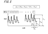
- FIG. 5 is a diagram illustrating an example of a pulse wave acquired with the wrist using the electronic device 100.
- FIG. 5 shows a case where the angular velocity sensor 131 is used as a pulsation detecting means.
- the angular velocity acquired by the angular velocity sensor 131 is integrated over time, the horizontal axis represents time, and the vertical axis represents the angle. Since the acquired pulse wave may include noise caused by the body movement of the subject, for example, correction by a filter that removes a DC (Direct Current) component may be performed to extract only the pulsation component.
- DC Direct Current
- the propagation of pulse waves is a phenomenon in which pulsation caused by blood pushed out of the heart travels through the walls of the artery and blood.
- the pulsation caused by the blood pushed out of the heart reaches the periphery of the limb as a forward wave, and a part of the pulsation is reflected by the branching portion of the blood vessel, the blood vessel diameter changing portion, etc., and returns as a reflected wave.
- the index based on the pulse wave is, for example, the pulse wave velocity PWV (Pulse Wave Velocity) of the forward wave, the magnitude P R of the reflected wave of the pulse wave, the time difference ⁇ t between the forward wave and the reflected wave of the pulse wave, It is AI (Augmentation Index) represented by the ratio of the magnitude of the forward wave and the reflected wave.
- PWV Pulse Wave Velocity
- AI Absolute Wave Velocity
- the pulse wave shown in FIG. 5 is a user's pulse for n times, and n is an integer of 1 or more.
- the pulse wave is a composite wave in which a forward wave generated by ejection of blood from the heart and a reflected wave generated from a blood vessel branching or a blood vessel diameter changing portion overlap.
- the pulse wave peak magnitude of the forward wave for each pulse is P Fn
- the pulse wave peak magnitude of the reflected wave for each pulse is P Rn
- the minimum value of the pulse wave for each pulse is P Sn . Show. Further, in FIG. 5, showing the spacing of the peaks of the pulse at T PR.
- the index based on the pulse wave is obtained by quantifying information obtained from the pulse wave.
- PWV which is one of indices based on pulse waves
- PWV is calculated based on the difference in propagation time of pulse waves measured at two test sites such as the upper arm and ankle and the distance between the two points.
- PWV is acquired by synchronizing pulse waves (for example, the upper arm and ankle) at two points in the artery, and the difference in distance (L) between the two points is divided by the time difference (PTT) between the two points. Is calculated.
- the magnitude P R of the reflected wave which is one of the indicators based on the pulse wave
- the magnitude P R of the reflected wave may be calculated as the peak magnitude P Rn of the pulse wave due to the reflected wave, or P Rave averaged over n times. It may be calculated.
- the time difference ⁇ t between the forward wave and the reflected wave of the pulse wave, which is one of the indicators based on the pulse wave may be calculated as a time difference ⁇ t n in a predetermined pulse, or ⁇ t obtained by averaging n time differences. ave may be calculated.
- AI n is the AI for each pulse.
- the pulse wave propagation velocity PWV, the magnitude of the reflected wave P R , the time difference ⁇ t between the forward wave and the reflected wave, and AI change depending on the hardness of the blood vessel wall, and therefore are used to estimate the state of arteriosclerosis. Can do. For example, if the blood vessel wall is hard, the pulse wave propagation speed PWV increases. For example, if the blood vessel wall is hard, the magnitude P R of the reflected wave increases. For example, if the blood vessel wall is hard, the time difference ⁇ t between the forward wave and the reflected wave becomes small. For example, if the blood vessel wall is hard, AI increases.
- the electronic device 100 can estimate the state of arteriosclerosis and the blood fluidity (viscosity) using the index based on these pulse waves.
- the electronic device 100 detects the blood fluidity from the change in the index based on the pulse wave acquired in the same subject site of the same subject and the period when the arteriosclerosis state does not substantially change (for example, within several days).
- the blood fluidity indicates the ease of blood flow. For example, when the blood fluidity is low, the pulse wave propagation velocity PWV is small. For example, the low fluidity of the blood, the size P R of the reflected wave is reduced. For example, when the blood fluidity is low, the time difference ⁇ t between the forward wave and the reflected wave becomes large. For example, when blood fluidity is low, AI becomes small.
- an index based on pulse waves electronic device 100 calculates pulse wave propagation speed PWV, reflected wave magnitude P R , time difference ⁇ t between forward wave and reflected wave, and AI.
- the index based on the pulse wave is not limited to this.
- the electronic device 100 may use posterior systolic blood pressure as an index based on a pulse wave.
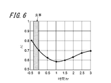
- FIG. 6 is a diagram illustrating the time variation of the calculated AI.
- the pulse wave is acquired for about 5 seconds using the electronic device 100 including the angular velocity sensor 131.
- the control unit 143 calculates AI for each pulse from the acquired pulse wave, and further calculates an average value AI ave thereof.
- electronic device 100 acquires a pulse wave at a plurality of timings before and after a meal, and calculates an average value of AI (hereinafter referred to as AI) as an example of an index based on the acquired pulse wave. did.
- the horizontal axis of FIG. 6 shows the passage of time, with the first measurement time after meal being zero.
- the vertical axis in FIG. 6 indicates the AI calculated from the pulse wave acquired at that time.
- the subject was at rest and a pulse wave was acquired on the radial artery.
- the electronic device 100 acquires pulse waves before a meal, immediately after a meal, and every 30 minutes after a meal, and calculates a plurality of AIs based on each pulse wave.
- the AI calculated from the pulse wave acquired before the meal was about 0.8. Compared to before the meal, the AI immediately after the meal was small, and the AI reached the minimum extreme value about 1 hour after the meal. The AI gradually increased until the measurement was completed 3 hours after the meal.
- the electronic device 100 can estimate a change in blood fluidity from the calculated change in AI. For example, when the red blood cells, white blood cells, and platelets in the blood harden in a dumpling shape or the adhesive strength increases, the fluidity of blood decreases. For example, when the water content of plasma in blood decreases, blood fluidity decreases. These changes in blood fluidity vary depending on, for example, the glycolipid state described later, and the health condition of the subject such as heat stroke, dehydration, and hypothermia. Before the subject's health condition becomes serious, the subject can know the change in fluidity of his blood using the electronic device 100 of the present embodiment. From the change in AI before and after the meal shown in FIG.
- the electronic device 100 may notify the state in which the blood fluidity is low by expressing it as “sloppy” and the state in which the blood fluidity is high as “smooth”. For example, the electronic device 100 may perform the determination of “muddy” or “smooth” based on the average value of AI at the actual age of the subject. The electronic device 100 may determine “smooth” if the calculated AI is larger than the average value, and “muddy” if the calculated AI is smaller than the average value. For example, the electronic device 100 may determine “smooth” or “smooth” based on AI before meal.
- the electronic device 100 may estimate the “muddy” degree by comparing the AI after the meal with the AI before the meal.
- the electronic device 100 can be used as an index of the blood vessel age (blood vessel hardness) of the subject, for example, as AI before meal, that is, AI during fasting.
- the electronic device 100 calculates the change amount of the calculated AI based on the AI before the subject's meal, that is, the fasting AI, the estimation based on the blood vessel age (blood vessel hardness) of the subject. Since errors can be reduced, changes in blood fluidity can be estimated more accurately.
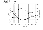
- FIG. 7 is a diagram showing the calculated AI and blood glucose level measurement results.
- the pulse wave acquisition method and the AI calculation method are the same as those in the embodiment shown in FIG.
- the right vertical axis in FIG. 7 indicates the blood glucose level in the blood
- the left vertical axis indicates the calculated AI.
- the solid line in FIG. 7 indicates the AI calculated from the acquired pulse wave
- the dotted line indicates the measured blood glucose level.
- the blood glucose level was measured immediately after acquiring the pulse wave.
- the blood glucose level was measured using a blood glucose meter “Medisafe Fit” manufactured by Terumo. Compared with the blood glucose level before the meal, the blood glucose level immediately after the meal is increased by about 20 mg / dl.
- the blood glucose level reached its maximum extreme value about 1 hour after the meal. Thereafter, the blood glucose level gradually decreased until the measurement was completed, and became approximately the same as the blood glucose level before the meal about 3 hours after the meal.
- the blood glucose level after the pre-meal has a negative correlation with the AI calculated from the pulse wave.
- the blood glucose level increases, red blood cells and platelets harden in the form of dumplings due to sugar in the blood, or the adhesive strength increases, and as a result, the blood fluidity may decrease.
- the pulse wave velocity PWV may decrease.
- the pulse wave propagation velocity PWV decreases, the time difference ⁇ t between the forward wave and the reflected wave may increase.
- the size P R of the reflected wave with respect to the size P F of the forward wave may be less.
- AI may be smaller. Since AI within a few hours after a meal (3 hours in the present embodiment) has a correlation with blood glucose level, the fluctuation of blood glucose level of the subject can be estimated by the fluctuation of AI. In addition, if the blood glucose level of the subject is measured in advance and the correlation with AI is acquired, the electronic device 100 can estimate the blood glucose level of the subject from the calculated AI.
- the electronic device 100 can estimate the state of glucose metabolism of the subject based on the occurrence time of AI P that is the minimum extreme value of AI first detected after a meal.
- the electronic device 100 estimates a blood glucose level, for example, as the state of sugar metabolism.
- a blood glucose level for example, as the state of sugar metabolism.
- the electronic device 100 It can be estimated that the subject has an abnormal glucose metabolism (diabetic patient).
- the electronic device 100 determines the glucose metabolism of the subject. Can be estimated.
- (AI B ⁇ AI P ) is a predetermined numerical value or more (for example, 0.5 or more), it can be estimated that the subject has abnormal glucose metabolism (postprandial hyperglycemia patient).
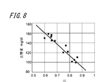
- FIG. 8 is a diagram showing the relationship between the calculated AI and blood glucose level.
- the calculated AI and blood glucose level are acquired within 1 hour after a meal with a large fluctuation in blood glucose level.
- the data in FIG. 8 includes a plurality of different post-meal data in the same subject.
- the calculated AI and blood glucose level showed a negative correlation.
- the correlation coefficient between the calculated AI and blood glucose level was 0.9 or more, indicating a very high correlation.
- the electronic device 100 can also estimate the blood glucose level of the subject from the calculated AI. .
- FIG. 9 is a diagram showing measurement results of the calculated AI and triglyceride value.
- the pulse wave acquisition method and the AI calculation method are the same as those in the embodiment shown in FIG.
- the right vertical axis in FIG. 9 indicates blood triglyceride level, and the left vertical axis indicates AI.
- the solid line in FIG. 9 indicates the AI calculated from the acquired pulse wave, and the dotted line indicates the measured triglyceride value.
- the neutral fat value was measured immediately after acquiring the pulse wave.
- the neutral fat value was measured using a lipid measuring device “Pocket Lipid” manufactured by Techno Medica. Compared to the neutral fat value before meal, the maximum extreme value of the neutral fat value after meal is increased by about 30 mg / dl. About 2 hours after the meal, the neutral fat reached its maximum extreme value. Thereafter, the triglyceride value gradually decreased until the measurement was completed, and became approximately the same as the triglyceride value before the meal at about 3.5 hours after the meal.
- the first minimum extreme value AI P1 was detected about 30 minutes after the meal
- the second minimum extreme value AI P2 was detected about 2 hours after the meal.
- the first minimum extreme value AI P1 detected about 30 minutes after the meal is due to the influence of the blood glucose level after the meal described above.
- the second minimum extreme value AI P2 detected about 2 hours after the meal almost coincides with the maximum extreme value of neutral fat detected about 2 hours after the meal. From this, it can be estimated that the second minimum extreme value AI P2 detected after a predetermined time from the meal is due to the influence of neutral fat.
- the triglyceride level after the pre-meal was found to have a negative correlation with the AI calculated from the pulse wave, similarly to the blood glucose level.
- the minimum extreme value AI P2 of AI detected after a predetermined time from the meal (after about 1.5 hours in the present embodiment) has a correlation with the triglyceride value.
- the fluctuation of the triglyceride level of a person can be estimated.
- the electronic device 100 can estimate the neutral fat value of the subject from the calculated AI. .
- the electronic device 100 can estimate the lipid metabolism state of the subject.
- the electronic device 100 estimates a lipid value, for example, as the state of lipid metabolism.
- the electronic device 100 indicates that the subject is abnormal in lipid metabolism. (Hyperlipidemic patient).
- the electronic device 100 determines the lipid of the subject. Metabolic status can be estimated. As an estimation example of lipid metabolism abnormality, for example, when (AI B -AI P2 ) is 0.5 or more, the electronic device 100 can estimate that the subject has a lipid metabolism abnormality (postprandial hyperlipidemia patient).
- the electronic device 100 determines the subject based on the first minimum extreme value AI P1 detected earliest after meal and the generation time thereof.
- the state of sugar metabolism can be estimated.
- the electronic device 100 according to the present embodiment is configured so that the subject's subject is based on the second minimum extreme value AI P2 detected after a predetermined time after the first minimum extreme value AI P1 and the generation time thereof.
- the state of lipid metabolism can be estimated.
- the case of neutral fat has been described as an example of estimation of lipid metabolism, but estimation of lipid metabolism is not limited to neutral fat.
- the lipid level estimated by the electronic device 100 includes, for example, total cholesterol, good (HDL: High Density Lipoprotein) cholesterol, and bad (LDL: Low Density Lipoprotein) cholesterol. These lipid values also show the same tendency as in the case of the neutral fat described above.
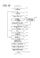
- FIG. 10 is a flowchart showing a procedure for estimating blood fluidity, sugar metabolism, and lipid metabolism based on AI. With reference to FIG. 10, the flow of blood fluidity and the estimation of the state of sugar metabolism and lipid metabolism by electronic device 100 according to the embodiment will be described.
- the electronic device 100 acquires the subject's AI reference value as an initial setting (step S101).
- the average AI estimated from the age of the subject may be used as the AI reference value, or the fasting AI of the subject acquired in advance may be used.
- electronic device 100 may use AI determined to be before meals in steps S102 to S108 as an AI reference value, or may use AI calculated immediately before pulse wave measurement as an AI reference value. In this case, electronic device 100 executes step S101 after steps S102 to S108.
- the electronic device 100 acquires a pulse wave (step S102). For example, the electronic device 100 determines whether or not a predetermined amplitude or more has been obtained for the pulse wave acquired during a predetermined measurement time (for example, 5 seconds). If the acquired pulse wave has a predetermined amplitude or more, the process proceeds to step S103. If the predetermined amplitude or more is not obtained, step S102 is repeated (these steps are not shown). In step S102, for example, when the electronic device 100 detects a pulse wave having a predetermined amplitude or more, the electronic device 100 automatically acquires the pulse wave.
- the electronic device 100 calculates AI as an index based on the pulse wave from the pulse wave acquired in step S102 and stores it in the storage unit 145 (step S103).
- electronic device 100 may calculate AI at a specific pulse.
- AI may be calculated with correction based on, for example, the pulse rate PR, the pulse pressure (P F ⁇ P S ), the body temperature, the temperature of the detected part, and the like. It is known that both pulse and AI and pulse pressure and AI have a negative correlation, and temperature and AI have a positive correlation.
- the electronic device 100 calculates a pulse and a pulse pressure in addition to the AI.
- the electronic device 100 may include a temperature sensor in the sensor unit 130, and may acquire the temperature of the detected portion when acquiring the pulse wave in step S102.
- the AI is corrected by substituting the acquired pulse, pulse pressure, temperature and the like into a correction formula created in advance.
- the electronic device 100 compares the AI reference value acquired in step S101 with the AI calculated in step S103, and estimates the blood fluidity of the subject (step S104).
- the calculated AI is larger than the AI reference value (in the case of YES)
- the electronic device 100 notifies, for example, “the blood is smooth” (step S105).
- the calculated AI is not larger than the AI reference value (in the case of NO)
- the electronic device 100 notifies, for example, “blood is muddy” (step S106).
- the electronic device 100 confirms with the subject whether or not to estimate the state of sugar metabolism and lipid metabolism (step S107).
- step S107 the electronic device 100 ends the process.
- step S108 the electronic device 100 checks whether the calculated AI is acquired before or after a meal (step S108). If it is not after a meal (before a meal) (in the case of NO), the process returns to step S102 to acquire the next pulse wave. In the case of after eating (in the case of YES), electronic device 100 stores the pulse wave acquisition time corresponding to the calculated AI (step S109).
- step S110 when acquiring a pulse wave (in the case of NO of step S110), it returns to step S102 and acquires the next pulse wave.
- the pulse wave measurement ends in the case of YES in step S110
- the process proceeds to step S111 and subsequent steps, and the electronic device 100 estimates the sugar metabolism and lipid metabolism of the subject.
- the electronic device 100 extracts the minimum extreme value and its time from the plurality of AIs calculated in Step S104 (Step S111). For example, when the AI as shown by the solid line in FIG. 9 is calculated, the electronic device 100 determines that the first minimum extreme value AI P1 about 30 minutes after the meal and the second minimum extreme value about 2 hours after the meal. Extract AI P2 .
- the electronic device 100 estimates the sugar metabolism state of the subject from the first minimum extreme value AI P1 and the time (step S112). Furthermore, the electronic device 100 estimates the lipid metabolism state of the subject from the second minimum extreme value AI P2 and the time (step S113).
- An example of estimating the state of sugar metabolism and lipid metabolism of the subject is the same as that in FIG.
- the electronic device 100 notifies the estimation results of step S112 and step S113 (step S114), and ends the process shown in FIG.
- the notification unit 147 reports, for example, “sugar metabolism is normal”, “sugar metabolism abnormality is suspected”, “lipid metabolism is normal”, “lipid metabolism abnormality is suspected”, and the like.
- the notification unit 147 may notify advice such as “Let's consult a hospital” and “Let's review the diet”. And the electronic device 100 complete
- the electronic device 100 can estimate the blood fluidity, sugar metabolism, and lipid metabolism of the subject from the index based on the pulse wave. For this reason, the electronic device 100 can estimate the blood fluidity, sugar metabolism, and lipid metabolism of the subject in a non-invasive and short time.
- the electronic device 100 can estimate the state of sugar metabolism and the state of lipid metabolism from the extreme value of the index based on the pulse wave and its time. Therefore, the electronic device 100 can estimate the sugar metabolism and lipid metabolism of the subject in a non-invasive and short time.
- the electronic device 100 can estimate the state of sugar metabolism and lipid metabolism of the subject on the basis of, for example, an index based on a pulse wave before meals (fasting). Therefore, it is possible to accurately estimate the blood fluidity, sugar metabolism, and lipid metabolism of the subject without taking into consideration the blood vessel diameter and the hardness of the blood vessel that do not change in the short term.
- the electronic device 100 can non-invasively and quickly measure the blood glucose level and lipid level of the subject by calibrating the index based on the pulse wave, the blood glucose level, and the lipid level. Can be estimated.
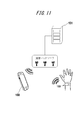
- FIG. 11 is a schematic diagram showing a schematic configuration of a system according to an embodiment of the present invention.
- the system according to the first embodiment shown in FIG. 11 includes an electronic device 100, a server 151, a mobile terminal 150, and a communication network.
- the index based on the pulse wave calculated by the electronic device 100 is transmitted to the server 151 through the communication network, and is stored in the server 151 as personal information of the subject.
- the server 151 estimates the fluidity of the subject's blood and the state of sugar metabolism and lipid metabolism by comparing the subject's past acquired information and various databases.
- the server 151 further creates optimal advice for the subject.
- the server 151 returns the estimation result and advice to the mobile terminal 150 owned by the subject.
- the mobile terminal 150 can construct a system that notifies the received estimation result and advice from the display unit of the mobile terminal 150.
- the server 151 can collect information from a plurality of users, so that the estimation accuracy is further improved.
- the portable terminal 150 is used as a notification unit, the electronic device 100 does not require the notification unit 147 and is further downsized.
- the server 151 estimates the blood fluidity, sugar metabolism, and lipid metabolism of the subject, the calculation burden on the control unit 143 of the electronic device 100 can be reduced.
- the burden on the storage unit 145 of the electronic device 100 can be reduced. Therefore, the electronic device 100 can be further downsized and simplified. In addition, the processing speed of calculation is improved.
- the system according to the present embodiment shows a configuration in which the electronic device 100 and the mobile terminal 150 are connected via a communication network via the server 151, but the system according to the present invention is not limited to this. Instead of using the server 151, the electronic device 100 and the portable terminal 150 may be directly connected via a communication network.
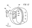
- FIG. 12 is a schematic diagram showing a schematic configuration of an electronic apparatus according to the second embodiment of the present invention.
- description of the same parts as those of the first embodiment will be omitted, and different parts will be described.
- the electronic device 200 includes a mounting part 210 and a sensor part 230.
- the electronic device 200 measures the biological information of the subject while the subject is wearing the electronic device 200.
- the biological information measured by the electronic device 200 is a pulse wave of the subject that can be measured by the sensor unit 230.
- electronic device 200 is worn on the wrist of a subject and acquires a pulse wave.
- the mounting portion 210 is a band-like band formed of, for example, a flexible resin.
- the mounting portion 210 has a recess 242 formed therein.
- the electronic device 200 is attached to the subject with the sensor unit 230 inserted into the recess 242.
- the recess 242 has a size and a depth that allow the sensor unit 230 to enter the recess 242.
- An elastic body 240 and an attaching / detaching portion 241 are formed in the recess 242.
- the sensor unit 230 is supported by an attachment / detachment unit 241 formed in the recess 242 in a state where the sensor unit 230 is inserted into the recess 242.
- the sensor unit 230 is in contact with the elastic body 240 while being supported by the detachable unit 241.
- the elastic body 240 is made of, for example, a resin having an appropriate elastic modulus.
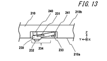
- FIG. 13 is a cross-sectional view showing a schematic configuration around the sensor unit 230 of the electronic device 200 shown in FIG. FIG. 13 also illustrates the mounting portion 210 around the sensor portion 230.
- the sensor unit 230 includes an angular velocity sensor 231 that detects the displacement of the sensor unit 230.
- the angular velocity sensor 231 only needs to detect the angle change of the sensor unit 230.
- the sensor included in the sensor unit 230 is not limited to the angular velocity sensor 231 and may be, for example, an acceleration sensor, an angle sensor, or another motion sensor.
- the sensor unit 230 may include a plurality of these sensors.
- the subject measures the pulse wave by wrapping the mounting portion 210 around the wrist so that the pulse contact portion 232 of the sensor portion 230 is in contact with the site to be examined.
- the electronic device 200 measures the pulse wave of blood flowing through the ulnar artery or radial artery at the wrist of the subject.
- the mounting part 210 has a back surface 210a that comes into contact with the wrist of the subject at the time of mounting, and a surface 210b opposite to the back surface 210a.
- the mounting portion 210 has a recess 242 on the back surface 210a side.
- the sensor part 230 is supported by the detachable part 241 in a state where one end protrudes from the concave part 242 toward the back surface 210a in a state where the elastic body 240 is not pressed.
- a protruding portion 232 is provided at one end of the sensor portion 230 that protrudes.
- the pulse contact portion 232 is a protrusion having a diameter slightly larger than the diameter of the subject's artery, for example, a diameter of about 3 to 10 mm. The subject brings the pulse contact portion 232 into contact with the site to be examined. By providing the pulse contact portion 232, the sensor portion 230 can be easily brought into contact with the test site.
- the sensor part 230 has a support part 233 supported by the attaching / detaching part 241.
- the sensor unit 230 includes a displacement unit 234 that is displaced according to the pulse wave of the subject.
- the displacement part 234 of the sensor part 230 can be displaced in a direction substantially perpendicular to the plane of the back surface 210a (Z direction in the figure) according to the pulse wave of the subject.
- the support part 233 of the sensor part 230 is supported by the attachment part 210 by the attaching / detaching part 241 so that the displacement part 234 of the sensor part 230 is displaced according to the pulse wave.
- the detachable portion 241 is configured by a resin pocket into which the support portion 233 of the sensor portion 230 can be inserted.
- the displacement unit 234 is displaced about the support unit 233, so that the electronic apparatus 200 can detect a pulse wave as a change in the angle of the sensor unit 230.
- the sensor unit 230 is in contact with the mounting unit 210 via the elastic body 240 and can be displaced according to the pulse wave of the subject.
- the elastic body 240 may be selected from a resin or a spring having an optimal elastic modulus that allows the elastic body 240 to expand and contract in accordance with the pulse wave while maintaining contact with the test site of the sensor unit 230.
- silicon resin, epoxy resin, nylon resin or the like is used for the elastic body 240.
- the electronic device 200 is attached to the subject in a state in which the pulse contact portion 232 is in contact with the site to be examined.
- the subject can adjust the position at which the mounting portion 210 is wound so that the pulsed portion 232 contacts the epidermis on the ulnar artery or radial artery.
- the electronic device 200 can adjust the length of the mounting portion 210 according to the thickness of the wrist of the subject.
- FIG. 14 is a cross-sectional view showing a schematic configuration around the sensor unit when a leaf spring is used as an elastic body in the electronic apparatus according to the second embodiment of the present invention. That is, in this embodiment, the elastic body is configured by the leaf spring 340.
- the mounting portion 310 has a back surface 310a that contacts the wrist of the subject when mounted, and a surface 310b opposite to the back surface 310a.
- the mounting portion 310 includes a leaf spring 340 in a recess provided on the back surface 310a side. One surface of the leaf spring 340 is supported by the mounting portion 310, and the sensor portion 330 is mounted on the other surface.
- the leaf spring 340 extends according to the pulse wave of the subject.
- the support portion 333 in the sensor portion 330 is located near the bent portion of the leaf spring 340.
- the displacement part 334 shows the part displaced according to a subject's pulse wave.
- the displacement part 334 in the sensor part 330 can be displaced in a direction substantially perpendicular to the plane of the back surface 310a (Z direction in the figure) according to the pulse wave of the subject, as in the embodiment shown in FIG.
- the sensor unit 330 includes an angular velocity sensor 331 that detects the displacement of the sensor unit 330.
- the subject wraps the mounting portion 310 around the wrist so that the pulse-applying portion 332 of the sensor unit 330 is in contact with the region to be examined, and measures the pulse wave.
- an electronic device using the leaf spring 340 as an elastic body also generates a pulse wave as a change in the angle of the sensor unit 330. Can be detected.
- the leaf spring 340 has an optimal spring constant that bends in accordance with the pulse wave while maintaining contact with the test site of the sensor unit 330.
- the leaf spring 340 for example, stainless steel, brass, phosphor bronze, beryllium copper or the like is used.
- the pulse wave can be measured with high accuracy.
- the electronic device according to the present embodiment can be worn on the subject, the pulse wave can be continuously measured, and the change in the physical condition of the subject can be known in real time. .
- measurement is possible without strongly squeezing the blood vessel, so even if it is worn for a long time, the burden on the subject is small and the wearability is excellent.
- accurate pulse waves can be acquired.
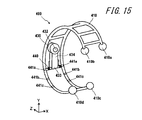
- FIG. 15 is a schematic diagram showing a schematic configuration of an electronic apparatus according to the third embodiment of the present invention.
- description of the same parts as those of the first and second embodiments will be omitted, and different parts will be described.
- the electronic device 400 includes a mounting unit 410 and a sensor unit 430.
- the electronic device 400 measures the pulse wave of the subject with the subject wearing the electronic device 400 on the wrist.
- the mounting portion 410 is formed of, for example, a metal having a spring property.
- the mounting portion 410 is, for example, a bracelet type with one end opened. The subject inserts his / her wrist into the mounting portion 410 by expanding the open end of the mounting portion 410 surrounded by the cushions 410a to 410d. The subject wears the attachment portion 410 so that the pulse contact portion 432 contacts the epidermis on the radial artery or the ulnar artery.
- the mounting portion 410 is mounted on the wrist of the subject with the open ends of the cushions 410a to 410d being pushed and spread. Due to the spring property of the mounting portion 410, the electronic device 400 can be mounted on the wrist of the subject.
- the sensor unit 430 is attached to an attachment / detachment unit 441a formed in the mounting unit 410 via a torsion coil spring 440 that is an elastic body.
- the torsion coil spring 440 is used as the elastic body.
- the present invention is not limited to this, and for example, a leaf spring, rubber, or the like may be used.
- the mounting part 410 includes a plurality of attaching / detaching parts 441a to 441c.
- the sensor unit 430 and the torsion coil spring 440 can be selectively attached to / detached from any of the plurality of attaching / detaching parts 441a to 441c.
- the sensor unit 430 can be attached to and detached from the plurality of attachment / detachment units 441a to 441c, so that the sensor unit 430 can be adjusted according to the thickness of the wrist of the subject and the position of the artery.
- the arrangement can be adjusted.
- the subject can adjust the mounting position of the mounting portion 410 on the wrist while visually observing so that the pulse contact portion 432 contacts the test site.
- the sensor part 430 is supported by the attaching / detaching part 441a in a state where one end protrudes to the wrist side (-Z direction in FIG. 15) when the torsion coil spring 440 is not expanded and contracted.
- a protruding portion 432 is provided at one end where the sensor portion 430 protrudes.
- the displacement part 434 in the sensor part 430 can be displaced in the Z direction in the figure in accordance with the pulse wave of the subject.
- the support part 433 in the sensor part 430 is supported by the attaching / detaching part 441a via the torsion coil spring 440 so that the displacement part 434 of the sensor part 430 is displaced according to the pulse wave.
- the sensor unit 430 is in contact with the mounting unit 410 via the torsion coil spring 440 and can be displaced according to the pulse wave of the subject.
- the torsion coil spring 440 has an optimal spring constant that bends in response to a pulse wave while maintaining contact with the test site.
- the electronic device 400 is attached to the subject in a state where the pulse contact portion 432 is in contact with the test site.
- the electronic device 400 may prepare a plurality of mounting portions 410 having different sizes according to the thickness of the wrist of the subject.
- the pulse wave can be measured with high accuracy.
- the electronic device according to the present embodiment can be worn on the subject, the pulse wave can be continuously measured, and the change in the physical condition of the subject can be known in real time. .
- measurement is possible without strongly squeezing the blood vessel, so even if it is worn for a long time, the burden on the subject is small and the wearability is excellent.
- accurate pulse waves can be acquired.
- the electronic device 100 includes the angular velocity sensor 131 .
- the sensor unit 130 may include an optical pulse wave sensor including a light emitting unit and a light receiving unit, or may include a pressure sensor.
- the mounting of the electronic device 100 is not limited to the wrist.
- the sensor part 130 should just be arrange
- the sugar metabolism and lipid metabolism states of the subject are determined.
- the electronic device according to the present invention is not limited to this.
- the extreme value may not appear, and the subject's sugar is determined based on the overall tendency (eg, integral value, Fourier transform, etc.) of the time variation of the index based on the calculated pulse wave.
- the state of metabolism and lipid metabolism may be estimated.
- the state of sugar metabolism and lipid metabolism of the subject is estimated based on the time range in which the index based on the pulse wave is below a predetermined value. May be. The same applies to the second and third embodiments.
- the electronic device according to the present invention may estimate blood fluidity before and after exercise, and may estimate blood fluidity before and after bathing and during bathing.
- the natural frequency of the sensor unit may be close to the frequency of the acquired pulse wave.
- the sensor unit may have any natural frequency in the range of 0.5 to 2 Hz.
- the natural frequency of the sensor unit can be optimized by changing the length, weight, elastic modulus, spring constant, etc. of the sensor unit. By optimizing the natural frequency of the sensor unit, the electronic device of the present invention can perform measurement with higher accuracy.
Abstract
Description
被検者に装着される装着部と、
前記被検者の脈波を検出するセンサを含むセンサ部と、備え、
前記センサ部は、前記装着部が前記被検者に装着されると前記被検者の被検部位に接触し、前記被検者の脈波に応じて変位する変位部を有する。 In order to solve the above problems, an electronic device according to the present invention is
A wearing part to be worn by the subject;
A sensor unit including a sensor for detecting the pulse wave of the subject,
The sensor part has a displacement part that contacts the subject site of the subject when the wearing part is attached to the subject and is displaced according to the pulse wave of the subject.
図1は、本発明の第1実施の形態に係る電子機器の概略構成を示す模式図である。電子機器100は、装着部110と、測定部120とを備える。図1は、被検部位に接触する裏面120aから電子機器100を観察した図である。 (First embodiment)
FIG. 1 is a schematic diagram showing a schematic configuration of an electronic apparatus according to the first embodiment of the present invention. The
図12は、本発明の第2実施の形態に係る電子機器の概略構成を示す模式図である。以下、第1実施の形態と同じ部分については説明を省略し、異なる部分について説明する。 (Second Embodiment)
FIG. 12 is a schematic diagram showing a schematic configuration of an electronic apparatus according to the second embodiment of the present invention. Hereinafter, description of the same parts as those of the first embodiment will be omitted, and different parts will be described.
図15は、本発明の第3実施の形態に係る電子機器の概略構成を示す模式図である。以下、第1及び第2実施の形態と同じ部分については説明を省略し、異なる部分について説明する。 (Third embodiment)
FIG. 15 is a schematic diagram showing a schematic configuration of an electronic apparatus according to the third embodiment of the present invention. Hereinafter, description of the same parts as those of the first and second embodiments will be omitted, and different parts will be described.
110、210、310、410 装着部
120 測定部
120a、210a、310a 裏面
120b、210b、310b 表面
111 開口部
130、230、330、430 センサ部
131、231、331 角速度センサ
132、232、332、432 脈あて部
133、233、333、433 支持部
140、240 弾性体
340 板ばね
440 ねじりコイルばね
143 制御部
144 電源部
145 記憶部
146 通信部
147 報知部
150 携帯端末
151 サーバ
234、334、434 変位部
241、441a、441b、441c 着脱部
242 凹部
410a、410b、410c、410d クッション 100, 200, 400
Claims (13)
- 被検者に装着される装着部と、
前記被検者の脈波を検出するセンサを含むセンサ部と、備え、
前記センサ部は、前記装着部が前記被検者に装着されると前記被検者の被検部位に接触し、前記被検者の脈波に応じて変位する変位部を有する、電子機器。 A wearing part to be worn by the subject;
A sensor unit including a sensor for detecting the pulse wave of the subject,
The sensor unit includes an displacing unit that contacts a test site of the subject when the mounting unit is mounted on the subject and is displaced according to the pulse wave of the subject. - 前記センサ部は、弾性体を介して前記装着部に接する、請求項1に記載の電子機器。 The electronic device according to claim 1, wherein the sensor unit is in contact with the mounting unit via an elastic body.
- 前記センサ部は支持部を有し、当該支持部は前記変位部が脈波に応じて変位可能なように前記装着部に支持される、請求項1又は2に記載の電子機器。 3. The electronic device according to claim 1, wherein the sensor unit includes a support unit, and the support unit is supported by the mounting unit so that the displacement unit can be displaced according to a pulse wave.
- 前記センサは、前記被検者の脈波に応じた前記センサ部の角度変化を検出する、請求項1乃至3のいずれか一項に記載の電子機器。 The electronic device according to any one of claims 1 to 3, wherein the sensor detects an angle change of the sensor unit according to the pulse wave of the subject.
- 前記センサ部の固有振動数は、前記被検者の脈波の振動数と略等しい、請求項1乃至4のいずれか一項に記載の電子機器。 5. The electronic device according to claim 1, wherein a natural frequency of the sensor unit is substantially equal to a frequency of a pulse wave of the subject.
- 前記センサ部の固有振動数は、0.5Hz以上2Hz以下の範囲のいずれかの振動数である、請求項1乃至5のいずれか一項に記載の電子機器。 The electronic device according to any one of claims 1 to 5, wherein the natural frequency of the sensor unit is any frequency in a range of 0.5 Hz to 2 Hz.
- 前記センサ部は、前記装着部に着脱可能である、請求項1乃至6のいずれか一項に記載の電子機器。 The electronic device according to any one of claims 1 to 6, wherein the sensor unit is detachable from the mounting unit.
- 前記装着部は、前記センサ部を着脱可能な複数の着脱部を有する、請求項7に記載の電子機器。 The electronic device according to claim 7, wherein the mounting unit includes a plurality of detachable units to which the sensor unit is detachable.
- 前記センサ部は、前記装着部が前記被検者の手首に装着されると、橈骨動脈上、又は尺骨動脈上の表皮に接触する、請求項1乃至8のいずれか一項に記載の電子機器。 The electronic device according to any one of claims 1 to 8, wherein the sensor unit contacts the epidermis on the radial artery or the ulnar artery when the mounting unit is mounted on the wrist of the subject. .
- 前記センサが検出した脈波に基づく指標を算出する制御部、をさらに備え
前記制御部は、前記算出された指標から前記被検者の糖代謝又は脂質代謝の状態を推定する、請求項1乃至9のいずれか一項に記載の電子機器。 The control part which calculates the parameter | index based on the pulse wave which the said sensor detected further, The said control part estimates the state of the said subject's glucose metabolism or lipid metabolism from the said calculated parameter | index. 10. The electronic device according to any one of 9 above. - 前記制御部は、前記センサが検出した脈波から反射波に関する指標を算出し、当該算出された反射波に関する指標から前記被検者の糖代謝又は脂質代謝の状態を推定する、請求項10に記載の電子機器。 The said control part calculates the parameter | index regarding a reflected wave from the pulse wave which the said sensor detected, and estimates the state of the said subject's glucose metabolism or lipid metabolism from the said parameter | index regarding the reflected wave. The electronic device described.
- 前記センサが検出した脈波に基づく指標を算出する制御部、をさらに備え
前記制御部は、前記算出された指標から前記被検者の血液の流動性を推定する、請求項1乃至9のいずれか一項に記載の電子機器。 The control part which calculates the parameter | index based on the pulse wave which the said sensor detected further, The said control part estimates the fluidity | liquidity of the said subject's blood from the calculated parameter | index. An electronic device according to any one of the above. - 前記制御部は、前記センサが検出した脈波から反射波に関する指標を算出し、当該算出された反射波に関する指標から前記被検者の血液の流動性を推定する、請求項12に記載の電子機器。 The electronic device according to claim 12, wherein the control unit calculates an index related to a reflected wave from the pulse wave detected by the sensor, and estimates the fluidity of the subject's blood from the calculated index related to the reflected wave. machine.
Priority Applications (5)
| Application Number | Priority Date | Filing Date | Title |
|---|---|---|---|
| US15/576,905 US10993632B2 (en) | 2015-05-29 | 2016-05-11 | Electronic device for detecting a pulse wave of a subject |
| CN201680030595.2A CN107613855B (en) | 2015-05-29 | 2016-05-11 | Electronic device |
| EP16802751.4A EP3305183B1 (en) | 2015-05-29 | 2016-05-11 | Electronic device |
| JP2017521668A JP6461334B2 (en) | 2015-05-29 | 2016-05-11 | Electronics |
| US17/213,085 US20210212585A1 (en) | 2015-05-29 | 2021-03-25 | Electronic device for detecting a pulse wave of a subject |
Applications Claiming Priority (2)
| Application Number | Priority Date | Filing Date | Title |
|---|---|---|---|
| JP2015109500 | 2015-05-29 | ||
| JP2015-109500 | 2015-05-29 |
Related Child Applications (2)
| Application Number | Title | Priority Date | Filing Date |
|---|---|---|---|
| US15/576,905 A-371-Of-International US10993632B2 (en) | 2015-05-29 | 2016-05-11 | Electronic device for detecting a pulse wave of a subject |
| US17/213,085 Continuation US20210212585A1 (en) | 2015-05-29 | 2021-03-25 | Electronic device for detecting a pulse wave of a subject |
Publications (1)
| Publication Number | Publication Date |
|---|---|
| WO2016194308A1 true WO2016194308A1 (en) | 2016-12-08 |
Family
ID=57440790
Family Applications (1)
| Application Number | Title | Priority Date | Filing Date |
|---|---|---|---|
| PCT/JP2016/002307 WO2016194308A1 (en) | 2015-05-29 | 2016-05-11 | Electronic device |
Country Status (5)
| Country | Link |
|---|---|
| US (2) | US10993632B2 (en) |
| EP (1) | EP3305183B1 (en) |
| JP (2) | JP6461334B2 (en) |
| CN (1) | CN107613855B (en) |
| WO (1) | WO2016194308A1 (en) |
Cited By (10)
| Publication number | Priority date | Publication date | Assignee | Title |
|---|---|---|---|---|
| JP2018000460A (en) * | 2016-06-30 | 2018-01-11 | 京セラ株式会社 | Electronic apparatus and estimation system |
| JP6285086B1 (en) * | 2017-07-25 | 2018-02-28 | 株式会社E3 | Meal advice providing system and analyzer |
| JP2018029944A (en) * | 2017-06-05 | 2018-03-01 | 有限会社アイデーエム | Blood information display apparatus |
| WO2018116847A1 (en) * | 2016-12-21 | 2018-06-28 | 京セラ株式会社 | Equipment for vehicle, vehicle, biometric information measuring method, and biometric information measuring system |
| WO2019102815A1 (en) | 2017-11-22 | 2019-05-31 | 京セラ株式会社 | Electronic device |
| WO2019211961A1 (en) | 2018-05-01 | 2019-11-07 | 京セラ株式会社 | Electronic device |
| WO2020105436A1 (en) | 2018-11-19 | 2020-05-28 | 京セラ株式会社 | Electronic machine |
| JP2020526353A (en) * | 2017-07-21 | 2020-08-31 | コーニンクレッカ フィリップス エヌ ヴェKoninklijke Philips N.V. | A device that measures physiological parameters using a wearable sensor |
| EP3756540A4 (en) * | 2018-02-22 | 2021-11-24 | Kyocera Corporation | Electronic device, estimation system, estimation method, and estimation program |
| JP7389463B2 (en) | 2019-11-25 | 2023-11-30 | 株式会社oneA | Biological information measuring device |
Families Citing this family (3)
| Publication number | Priority date | Publication date | Assignee | Title |
|---|---|---|---|---|
| JP6685811B2 (en) * | 2016-04-08 | 2020-04-22 | 京セラ株式会社 | Electronic equipment and estimation system |
| JP6763897B2 (en) * | 2018-02-22 | 2020-09-30 | 京セラ株式会社 | Electronics, estimation systems, estimation methods and estimation programs |
| JP7077776B2 (en) * | 2018-05-24 | 2022-05-31 | オムロンヘルスケア株式会社 | Blood pressure measuring device |
Citations (5)
| Publication number | Priority date | Publication date | Assignee | Title |
|---|---|---|---|---|
| US5406952A (en) * | 1993-02-11 | 1995-04-18 | Biosyss Corporation | Blood pressure monitoring system |
| JP2000005139A (en) * | 1998-06-23 | 2000-01-11 | Seiko Epson Corp | Pulse wave detecting device and touch sense detecting device |
| JP2006129887A (en) * | 2004-11-02 | 2006-05-25 | Hitachi Ltd | Life condition notification system |
| JP2008183256A (en) * | 2007-01-31 | 2008-08-14 | Citizen Holdings Co Ltd | Blood viscosity measuring device and blood viscosity measuring method |
| JP2012075820A (en) * | 2010-10-06 | 2012-04-19 | Sharp Corp | Pulse wave propagation velocity measuring device and pulse wave propagation velocity measuring program |
Family Cites Families (23)
| Publication number | Priority date | Publication date | Assignee | Title |
|---|---|---|---|---|
| US3154066A (en) * | 1961-10-11 | 1964-10-27 | Robert L Gannon | Body function sensors |
| US4561447A (en) * | 1983-01-14 | 1985-12-31 | Nippon, Colin Co., Ltd. | Apparatus and method of detecting arterial pulse wave |
| US5362307A (en) * | 1989-01-24 | 1994-11-08 | The Regents Of The University Of California | Method for the iontophoretic non-invasive-determination of the in vivo concentration level of an inorganic or organic substance |
| ATE132720T1 (en) * | 1990-07-18 | 1996-01-15 | Avl Medical Instr Ag | DEVICE AND METHOD FOR MEASURING BLOOD PRESSURE |
| US5497779A (en) * | 1994-03-08 | 1996-03-12 | Colin Corporation | Pulse wave detecting apparatus |
| JP3605216B2 (en) * | 1995-02-20 | 2004-12-22 | セイコーエプソン株式会社 | Pulse meter |
| EP0922432B1 (en) * | 1997-03-25 | 2005-03-02 | Seiko Epson Corporation | Pulse wave measuring device |
| AU1198100A (en) * | 1998-09-23 | 2000-04-10 | Keith Bridger | Physiological sensing device |
| FI115289B (en) * | 2000-02-23 | 2005-04-15 | Polar Electro Oy | Measurement of an organism's energy metabolism and glucose levels |
| CN100398058C (en) * | 2000-04-21 | 2008-07-02 | 陆渭明 | Non-wound method and device for measuring blood pressure |
| US6549796B2 (en) * | 2001-05-25 | 2003-04-15 | Lifescan, Inc. | Monitoring analyte concentration using minimally invasive devices |
| JP2002360530A (en) | 2001-06-11 | 2002-12-17 | Waatekkusu:Kk | Pulse wave sensor and pulse rate detector |
| JP4036101B2 (en) * | 2003-01-21 | 2008-01-23 | オムロンヘルスケア株式会社 | Pressure pulse wave detection probe |
| US7445605B2 (en) * | 2003-01-31 | 2008-11-04 | The Board Of Trustees Of The Leland Stanford Junior University | Detection of apex motion for monitoring cardiac dysfunction |
| JP3692125B2 (en) | 2003-04-02 | 2005-09-07 | コーリンメディカルテクノロジー株式会社 | Heart sound detection device |
| JP4806958B2 (en) * | 2005-05-16 | 2011-11-02 | 株式会社デンソー | Mounting structure, device, and band fixing rod |
| EP2329769B1 (en) * | 2008-08-19 | 2015-03-25 | Delta Tooling Co., Ltd. | Biometric signal measuring device and organism condition analyzing system |
| US20120059237A1 (en) | 2009-05-04 | 2012-03-08 | Jack Amir | System and method for monitoring blood glucose levels non-invasively |
| JP5648796B2 (en) | 2010-11-16 | 2015-01-07 | セイコーエプソン株式会社 | Vital sign measuring device |
| CN103070678A (en) * | 2013-02-21 | 2013-05-01 | 沈阳恒德医疗器械研发有限公司 | Non-invasive central arterial pressure detector and detection method thereof |
| JP6177892B2 (en) | 2013-04-16 | 2017-08-09 | 京セラ株式会社 | Device and device control method |
| US11229383B2 (en) * | 2014-08-25 | 2022-01-25 | California Institute Of Technology | Methods and systems for non-invasive measurement of blood glucose concentration by transmission of millimeter waves through human skin |
| CN111297332A (en) * | 2015-04-28 | 2020-06-19 | 京瓷株式会社 | Electronic device and system |
-
2016
- 2016-05-11 JP JP2017521668A patent/JP6461334B2/en active Active
- 2016-05-11 US US15/576,905 patent/US10993632B2/en active Active
- 2016-05-11 WO PCT/JP2016/002307 patent/WO2016194308A1/en active Application Filing
- 2016-05-11 EP EP16802751.4A patent/EP3305183B1/en active Active
- 2016-05-11 CN CN201680030595.2A patent/CN107613855B/en active Active
-
2018
- 2018-12-25 JP JP2018241787A patent/JP6688379B2/en active Active
-
2021
- 2021-03-25 US US17/213,085 patent/US20210212585A1/en active Pending
Patent Citations (5)
| Publication number | Priority date | Publication date | Assignee | Title |
|---|---|---|---|---|
| US5406952A (en) * | 1993-02-11 | 1995-04-18 | Biosyss Corporation | Blood pressure monitoring system |
| JP2000005139A (en) * | 1998-06-23 | 2000-01-11 | Seiko Epson Corp | Pulse wave detecting device and touch sense detecting device |
| JP2006129887A (en) * | 2004-11-02 | 2006-05-25 | Hitachi Ltd | Life condition notification system |
| JP2008183256A (en) * | 2007-01-31 | 2008-08-14 | Citizen Holdings Co Ltd | Blood viscosity measuring device and blood viscosity measuring method |
| JP2012075820A (en) * | 2010-10-06 | 2012-04-19 | Sharp Corp | Pulse wave propagation velocity measuring device and pulse wave propagation velocity measuring program |
Non-Patent Citations (1)
| Title |
|---|
| See also references of EP3305183A4 * |
Cited By (18)
| Publication number | Priority date | Publication date | Assignee | Title |
|---|---|---|---|---|
| JP2018000460A (en) * | 2016-06-30 | 2018-01-11 | 京セラ株式会社 | Electronic apparatus and estimation system |
| WO2018116847A1 (en) * | 2016-12-21 | 2018-06-28 | 京セラ株式会社 | Equipment for vehicle, vehicle, biometric information measuring method, and biometric information measuring system |
| JPWO2018116847A1 (en) * | 2016-12-21 | 2019-10-24 | 京セラ株式会社 | Vehicle equipment, vehicle, biological information measuring method, and biological information measuring system |
| JP2018029944A (en) * | 2017-06-05 | 2018-03-01 | 有限会社アイデーエム | Blood information display apparatus |
| JP2020526353A (en) * | 2017-07-21 | 2020-08-31 | コーニンクレッカ フィリップス エヌ ヴェKoninklijke Philips N.V. | A device that measures physiological parameters using a wearable sensor |
| JP6285086B1 (en) * | 2017-07-25 | 2018-02-28 | 株式会社E3 | Meal advice providing system and analyzer |
| WO2019021358A1 (en) * | 2017-07-25 | 2019-01-31 | 株式会社E3 | Meal advice providing system and analysis device |
| EP3714776A4 (en) * | 2017-11-22 | 2021-08-11 | Kyocera Corporation | Electronic device |
| WO2019102815A1 (en) | 2017-11-22 | 2019-05-31 | 京セラ株式会社 | Electronic device |
| JP2019093127A (en) * | 2017-11-22 | 2019-06-20 | 京セラ株式会社 | Electronic device and sensor unit |
| US20220287578A1 (en) * | 2017-11-22 | 2022-09-15 | Kyocera Corporation | Electronic device |
| EP3756540A4 (en) * | 2018-02-22 | 2021-11-24 | Kyocera Corporation | Electronic device, estimation system, estimation method, and estimation program |
| WO2019211961A1 (en) | 2018-05-01 | 2019-11-07 | 京セラ株式会社 | Electronic device |
| CN113038871A (en) * | 2018-11-19 | 2021-06-25 | 京瓷株式会社 | Electronic device |
| JP2020081086A (en) * | 2018-11-19 | 2020-06-04 | 京セラ株式会社 | Electronic apparatus |
| WO2020105436A1 (en) | 2018-11-19 | 2020-05-28 | 京セラ株式会社 | Electronic machine |
| US11594118B2 (en) | 2018-11-19 | 2023-02-28 | Kyocera Corporation | Electronic device |
| JP7389463B2 (en) | 2019-11-25 | 2023-11-30 | 株式会社oneA | Biological information measuring device |
Also Published As
| Publication number | Publication date |
|---|---|
| CN107613855A (en) | 2018-01-19 |
| EP3305183A1 (en) | 2018-04-11 |
| CN107613855B (en) | 2021-11-23 |
| EP3305183A4 (en) | 2019-01-30 |
| US20180146871A1 (en) | 2018-05-31 |
| US20210212585A1 (en) | 2021-07-15 |
| JPWO2016194308A1 (en) | 2017-12-07 |
| US10993632B2 (en) | 2021-05-04 |
| EP3305183B1 (en) | 2023-12-27 |
| JP2019063583A (en) | 2019-04-25 |
| JP6461334B2 (en) | 2019-01-30 |
| JP6688379B2 (en) | 2020-04-28 |
Similar Documents
| Publication | Publication Date | Title |
|---|---|---|
| JP6461334B2 (en) | Electronics | |
| JP7361830B2 (en) | electronic equipment and equipment | |
| JP6636872B2 (en) | Electronic equipment and estimation system | |
| JP2017185131A (en) | Electronic device and estimation system | |
| JP2020054880A (en) | Electronic device and sensor unit | |
| WO2020105436A1 (en) | Electronic machine | |
| WO2019211961A1 (en) | Electronic device | |
| JP7008682B2 (en) | Electronic equipment and estimation system | |
| JP7367242B2 (en) | Electronic equipment, estimation system, estimation method and estimation program |
Legal Events
| Date | Code | Title | Description |
|---|---|---|---|
| 121 | Ep: the epo has been informed by wipo that ep was designated in this application |
Ref document number: 16802751 Country of ref document: EP Kind code of ref document: A1 |
|
| ENP | Entry into the national phase |
Ref document number: 2017521668 Country of ref document: JP Kind code of ref document: A |
|
| WWE | Wipo information: entry into national phase |
Ref document number: 15576905 Country of ref document: US |
|
| NENP | Non-entry into the national phase |
Ref country code: DE |
|
| WWE | Wipo information: entry into national phase |
Ref document number: 2016802751 Country of ref document: EP |