WO2016190195A1 - Vehicle control device and method for controlling same - Google Patents
Vehicle control device and method for controlling same Download PDFInfo
- Publication number
- WO2016190195A1 WO2016190195A1 PCT/JP2016/064763 JP2016064763W WO2016190195A1 WO 2016190195 A1 WO2016190195 A1 WO 2016190195A1 JP 2016064763 W JP2016064763 W JP 2016064763W WO 2016190195 A1 WO2016190195 A1 WO 2016190195A1
- Authority
- WO
- WIPO (PCT)
- Prior art keywords
- target input
- speed
- rotation speed
- rotational speed
- vehicle control
- Prior art date
Links
Images


Classifications
-
- F—MECHANICAL ENGINEERING; LIGHTING; HEATING; WEAPONS; BLASTING
- F16—ENGINEERING ELEMENTS AND UNITS; GENERAL MEASURES FOR PRODUCING AND MAINTAINING EFFECTIVE FUNCTIONING OF MACHINES OR INSTALLATIONS; THERMAL INSULATION IN GENERAL
- F16H—GEARING
- F16H61/00—Control functions within control units of change-speed- or reversing-gearings for conveying rotary motion ; Control of exclusively fluid gearing, friction gearing, gearings with endless flexible members or other particular types of gearing
- F16H61/66—Control functions within control units of change-speed- or reversing-gearings for conveying rotary motion ; Control of exclusively fluid gearing, friction gearing, gearings with endless flexible members or other particular types of gearing specially adapted for continuously variable gearings
- F16H61/662—Control functions within control units of change-speed- or reversing-gearings for conveying rotary motion ; Control of exclusively fluid gearing, friction gearing, gearings with endless flexible members or other particular types of gearing specially adapted for continuously variable gearings with endless flexible members
-
- B—PERFORMING OPERATIONS; TRANSPORTING
- B60—VEHICLES IN GENERAL
- B60W—CONJOINT CONTROL OF VEHICLE SUB-UNITS OF DIFFERENT TYPE OR DIFFERENT FUNCTION; CONTROL SYSTEMS SPECIALLY ADAPTED FOR HYBRID VEHICLES; ROAD VEHICLE DRIVE CONTROL SYSTEMS FOR PURPOSES NOT RELATED TO THE CONTROL OF A PARTICULAR SUB-UNIT
- B60W10/00—Conjoint control of vehicle sub-units of different type or different function
- B60W10/04—Conjoint control of vehicle sub-units of different type or different function including control of propulsion units
- B60W10/06—Conjoint control of vehicle sub-units of different type or different function including control of propulsion units including control of combustion engines
-
- B—PERFORMING OPERATIONS; TRANSPORTING
- B60—VEHICLES IN GENERAL
- B60W—CONJOINT CONTROL OF VEHICLE SUB-UNITS OF DIFFERENT TYPE OR DIFFERENT FUNCTION; CONTROL SYSTEMS SPECIALLY ADAPTED FOR HYBRID VEHICLES; ROAD VEHICLE DRIVE CONTROL SYSTEMS FOR PURPOSES NOT RELATED TO THE CONTROL OF A PARTICULAR SUB-UNIT
- B60W10/00—Conjoint control of vehicle sub-units of different type or different function
- B60W10/10—Conjoint control of vehicle sub-units of different type or different function including control of change-speed gearings
- B60W10/101—Infinitely variable gearings
- B60W10/108—Friction gearings
-
- F—MECHANICAL ENGINEERING; LIGHTING; HEATING; WEAPONS; BLASTING
- F16—ENGINEERING ELEMENTS AND UNITS; GENERAL MEASURES FOR PRODUCING AND MAINTAINING EFFECTIVE FUNCTIONING OF MACHINES OR INSTALLATIONS; THERMAL INSULATION IN GENERAL
- F16H—GEARING
- F16H59/00—Control inputs to control units of change-speed-, or reversing-gearings for conveying rotary motion
- F16H59/14—Inputs being a function of torque or torque demand
- F16H59/18—Inputs being a function of torque or torque demand dependent on the position of the accelerator pedal
-
- F—MECHANICAL ENGINEERING; LIGHTING; HEATING; WEAPONS; BLASTING
- F16—ENGINEERING ELEMENTS AND UNITS; GENERAL MEASURES FOR PRODUCING AND MAINTAINING EFFECTIVE FUNCTIONING OF MACHINES OR INSTALLATIONS; THERMAL INSULATION IN GENERAL
- F16H—GEARING
- F16H59/00—Control inputs to control units of change-speed-, or reversing-gearings for conveying rotary motion
- F16H59/36—Inputs being a function of speed
- F16H59/38—Inputs being a function of speed of gearing elements
- F16H59/42—Input shaft speed
-
- F—MECHANICAL ENGINEERING; LIGHTING; HEATING; WEAPONS; BLASTING
- F16—ENGINEERING ELEMENTS AND UNITS; GENERAL MEASURES FOR PRODUCING AND MAINTAINING EFFECTIVE FUNCTIONING OF MACHINES OR INSTALLATIONS; THERMAL INSULATION IN GENERAL
- F16H—GEARING
- F16H61/00—Control functions within control units of change-speed- or reversing-gearings for conveying rotary motion ; Control of exclusively fluid gearing, friction gearing, gearings with endless flexible members or other particular types of gearing
- F16H61/02—Control functions within control units of change-speed- or reversing-gearings for conveying rotary motion ; Control of exclusively fluid gearing, friction gearing, gearings with endless flexible members or other particular types of gearing characterised by the signals used
- F16H61/0202—Control functions within control units of change-speed- or reversing-gearings for conveying rotary motion ; Control of exclusively fluid gearing, friction gearing, gearings with endless flexible members or other particular types of gearing characterised by the signals used the signals being electric
- F16H61/0204—Control functions within control units of change-speed- or reversing-gearings for conveying rotary motion ; Control of exclusively fluid gearing, friction gearing, gearings with endless flexible members or other particular types of gearing characterised by the signals used the signals being electric for gearshift control, e.g. control functions for performing shifting or generation of shift signal
- F16H61/0213—Control functions within control units of change-speed- or reversing-gearings for conveying rotary motion ; Control of exclusively fluid gearing, friction gearing, gearings with endless flexible members or other particular types of gearing characterised by the signals used the signals being electric for gearshift control, e.g. control functions for performing shifting or generation of shift signal characterised by the method for generating shift signals
-
- F—MECHANICAL ENGINEERING; LIGHTING; HEATING; WEAPONS; BLASTING
- F16—ENGINEERING ELEMENTS AND UNITS; GENERAL MEASURES FOR PRODUCING AND MAINTAINING EFFECTIVE FUNCTIONING OF MACHINES OR INSTALLATIONS; THERMAL INSULATION IN GENERAL
- F16H—GEARING
- F16H61/00—Control functions within control units of change-speed- or reversing-gearings for conveying rotary motion ; Control of exclusively fluid gearing, friction gearing, gearings with endless flexible members or other particular types of gearing
- F16H61/66—Control functions within control units of change-speed- or reversing-gearings for conveying rotary motion ; Control of exclusively fluid gearing, friction gearing, gearings with endless flexible members or other particular types of gearing specially adapted for continuously variable gearings
- F16H61/662—Control functions within control units of change-speed- or reversing-gearings for conveying rotary motion ; Control of exclusively fluid gearing, friction gearing, gearings with endless flexible members or other particular types of gearing specially adapted for continuously variable gearings with endless flexible members
- F16H61/66254—Control functions within control units of change-speed- or reversing-gearings for conveying rotary motion ; Control of exclusively fluid gearing, friction gearing, gearings with endless flexible members or other particular types of gearing specially adapted for continuously variable gearings with endless flexible members controlling of shifting being influenced by a signal derived from the engine and the main coupling
- F16H61/66259—Control functions within control units of change-speed- or reversing-gearings for conveying rotary motion ; Control of exclusively fluid gearing, friction gearing, gearings with endless flexible members or other particular types of gearing specially adapted for continuously variable gearings with endless flexible members controlling of shifting being influenced by a signal derived from the engine and the main coupling using electrical or electronical sensing or control means
-
- B—PERFORMING OPERATIONS; TRANSPORTING
- B60—VEHICLES IN GENERAL
- B60W—CONJOINT CONTROL OF VEHICLE SUB-UNITS OF DIFFERENT TYPE OR DIFFERENT FUNCTION; CONTROL SYSTEMS SPECIALLY ADAPTED FOR HYBRID VEHICLES; ROAD VEHICLE DRIVE CONTROL SYSTEMS FOR PURPOSES NOT RELATED TO THE CONTROL OF A PARTICULAR SUB-UNIT
- B60W2510/00—Input parameters relating to a particular sub-units
- B60W2510/06—Combustion engines, Gas turbines
- B60W2510/0638—Engine speed
-
- B—PERFORMING OPERATIONS; TRANSPORTING
- B60—VEHICLES IN GENERAL
- B60W—CONJOINT CONTROL OF VEHICLE SUB-UNITS OF DIFFERENT TYPE OR DIFFERENT FUNCTION; CONTROL SYSTEMS SPECIALLY ADAPTED FOR HYBRID VEHICLES; ROAD VEHICLE DRIVE CONTROL SYSTEMS FOR PURPOSES NOT RELATED TO THE CONTROL OF A PARTICULAR SUB-UNIT
- B60W2510/00—Input parameters relating to a particular sub-units
- B60W2510/10—Change speed gearings
- B60W2510/1005—Transmission ratio engaged
-
- B—PERFORMING OPERATIONS; TRANSPORTING
- B60—VEHICLES IN GENERAL
- B60W—CONJOINT CONTROL OF VEHICLE SUB-UNITS OF DIFFERENT TYPE OR DIFFERENT FUNCTION; CONTROL SYSTEMS SPECIALLY ADAPTED FOR HYBRID VEHICLES; ROAD VEHICLE DRIVE CONTROL SYSTEMS FOR PURPOSES NOT RELATED TO THE CONTROL OF A PARTICULAR SUB-UNIT
- B60W2530/00—Input parameters relating to vehicle conditions or values, not covered by groups B60W2510/00 or B60W2520/00
- B60W2530/13—Mileage
-
- B—PERFORMING OPERATIONS; TRANSPORTING
- B60—VEHICLES IN GENERAL
- B60W—CONJOINT CONTROL OF VEHICLE SUB-UNITS OF DIFFERENT TYPE OR DIFFERENT FUNCTION; CONTROL SYSTEMS SPECIALLY ADAPTED FOR HYBRID VEHICLES; ROAD VEHICLE DRIVE CONTROL SYSTEMS FOR PURPOSES NOT RELATED TO THE CONTROL OF A PARTICULAR SUB-UNIT
- B60W2540/00—Input parameters relating to occupants
- B60W2540/10—Accelerator pedal position
-
- F—MECHANICAL ENGINEERING; LIGHTING; HEATING; WEAPONS; BLASTING
- F16—ENGINEERING ELEMENTS AND UNITS; GENERAL MEASURES FOR PRODUCING AND MAINTAINING EFFECTIVE FUNCTIONING OF MACHINES OR INSTALLATIONS; THERMAL INSULATION IN GENERAL
- F16H—GEARING
- F16H59/00—Control inputs to control units of change-speed-, or reversing-gearings for conveying rotary motion
- F16H59/36—Inputs being a function of speed
- F16H2059/366—Engine or motor speed
-
- F—MECHANICAL ENGINEERING; LIGHTING; HEATING; WEAPONS; BLASTING
- F16—ENGINEERING ELEMENTS AND UNITS; GENERAL MEASURES FOR PRODUCING AND MAINTAINING EFFECTIVE FUNCTIONING OF MACHINES OR INSTALLATIONS; THERMAL INSULATION IN GENERAL
- F16H—GEARING
- F16H61/00—Control functions within control units of change-speed- or reversing-gearings for conveying rotary motion ; Control of exclusively fluid gearing, friction gearing, gearings with endless flexible members or other particular types of gearing
- F16H2061/0075—Control functions within control units of change-speed- or reversing-gearings for conveying rotary motion ; Control of exclusively fluid gearing, friction gearing, gearings with endless flexible members or other particular types of gearing characterised by a particular control method
- F16H2061/0096—Control functions within control units of change-speed- or reversing-gearings for conveying rotary motion ; Control of exclusively fluid gearing, friction gearing, gearings with endless flexible members or other particular types of gearing characterised by a particular control method using a parameter map
-
- F—MECHANICAL ENGINEERING; LIGHTING; HEATING; WEAPONS; BLASTING
- F16—ENGINEERING ELEMENTS AND UNITS; GENERAL MEASURES FOR PRODUCING AND MAINTAINING EFFECTIVE FUNCTIONING OF MACHINES OR INSTALLATIONS; THERMAL INSULATION IN GENERAL
- F16H—GEARING
- F16H61/00—Control functions within control units of change-speed- or reversing-gearings for conveying rotary motion ; Control of exclusively fluid gearing, friction gearing, gearings with endless flexible members or other particular types of gearing
- F16H61/02—Control functions within control units of change-speed- or reversing-gearings for conveying rotary motion ; Control of exclusively fluid gearing, friction gearing, gearings with endless flexible members or other particular types of gearing characterised by the signals used
- F16H61/0202—Control functions within control units of change-speed- or reversing-gearings for conveying rotary motion ; Control of exclusively fluid gearing, friction gearing, gearings with endless flexible members or other particular types of gearing characterised by the signals used the signals being electric
- F16H61/0204—Control functions within control units of change-speed- or reversing-gearings for conveying rotary motion ; Control of exclusively fluid gearing, friction gearing, gearings with endless flexible members or other particular types of gearing characterised by the signals used the signals being electric for gearshift control, e.g. control functions for performing shifting or generation of shift signal
- F16H61/0213—Control functions within control units of change-speed- or reversing-gearings for conveying rotary motion ; Control of exclusively fluid gearing, friction gearing, gearings with endless flexible members or other particular types of gearing characterised by the signals used the signals being electric for gearshift control, e.g. control functions for performing shifting or generation of shift signal characterised by the method for generating shift signals
- F16H2061/0234—Adapting the ratios to special vehicle conditions
-
- F—MECHANICAL ENGINEERING; LIGHTING; HEATING; WEAPONS; BLASTING
- F16—ENGINEERING ELEMENTS AND UNITS; GENERAL MEASURES FOR PRODUCING AND MAINTAINING EFFECTIVE FUNCTIONING OF MACHINES OR INSTALLATIONS; THERMAL INSULATION IN GENERAL
- F16H—GEARING
- F16H59/00—Control inputs to control units of change-speed-, or reversing-gearings for conveying rotary motion
- F16H59/14—Inputs being a function of torque or torque demand
- F16H59/18—Inputs being a function of torque or torque demand dependent on the position of the accelerator pedal
- F16H59/22—Idle position
Definitions
- the present invention relates to a vehicle control device and a control method therefor.
- JP2010-209882A discloses a control device for shifting a continuously variable transmission based on a shift map set lower than the rotation speed).
- a torque converter having a lock-up clutch is generally disposed between a drive source and a continuously variable transmission.
- the lock-up clutch is engaged during deceleration, and the engine rotation shaft is driven from the drive wheels.
- the fuel cut is executed to stop the fuel injection to the engine while the rotation is transmitted to the engine. Thereby, the fuel consumption in an engine can be improved.
- the transmission is controlled using the shift map in the above technology, for example, in the following scene, the engine speed decreases during deceleration, the lockup clutch is released, and fuel injection to the engine is performed.
- the fuel cut recovery to be performed may be executed.
- a release rotation speed for releasing the lock-up clutch is set so that the engine rotation speed decreases with the vehicle speed and the engine does not stall.
- the release rotational speed is set to a value slightly lower than the first target input rotational speed.
- the target input rotation speed decreases to the first target input rotation speed, and then the second target input rotation when the accelerator pedal opening becomes zero. Increases to speed.
- the gear ratio of the continuously variable transmission is changed to a gear ratio corresponding to the second target input rotation speed after being changed to a gear ratio corresponding to the first target input rotation speed.
- the actual input rotation speed becomes lower than the first target input rotation speed due to a response delay due to a time constant, an operation delay, etc.
- the speed may be lower than the release rotation speed.
- the present invention has been invented to solve such problems. For example, when the vehicle is decelerating, the release of the lock-up clutch is suppressed, and the reduction of the fuel consumption of the engine is suppressed.
- the purpose is to do.
- a vehicle control device includes a continuously variable transmission provided between an engine and a drive wheel, and a continuously variable transmission arranged in series, wherein the rotational speed of the engine is lower than the release rotational speed.
- the first target input rotational speed of the continuously variable transmission which is set when the accelerator pedal opening is zero, is that the accelerator pedal is opened.
- Control means for controlling the transmission ratio of the continuously variable transmission based on a shift map set higher than the second target input rotational speed of the continuously variable transmission set when the degree of opening is greater than zero.
- the control means includes a third target input rotation speed that is higher than the second target input rotation speed when the accelerator pedal operation is performed so that the accelerator pedal opening is equal to or less than a predetermined opening. Set to.
- a vehicle control method includes a continuously variable transmission provided between an engine and a drive wheel, and a continuously variable transmission arranged in series, wherein the rotational speed of the engine is higher than the release rotational speed.
- a vehicle control method for controlling a transmission including a frictional engagement element that is released when the accelerator pedal is lowered, wherein the first target input rotational speed of the continuously variable transmission that is set when the accelerator pedal opening is zero is Controlling the gear ratio of the continuously variable transmission based on a shift map set higher than the second target input rotation speed of the continuously variable transmission set when the pedal opening is a predetermined opening larger than zero;
- the target input rotation speed of the continuously variable transmission is set to a third target input rotation speed that is higher than the second target input rotation speed.
- the target input rotation speed of the continuously variable transmission is set to the third target input rotation speed higher than the second target input rotation speed.
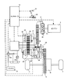
- FIG. 1 is a schematic configuration diagram of a vehicle according to the first embodiment.
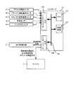
- FIG. 2 is a schematic configuration diagram of the controller of the first embodiment.
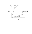
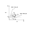
- FIG. 3 is a shift map according to the first embodiment.
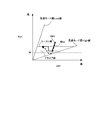
- FIG. 4 is a diagram showing a change in the input rotation speed when this embodiment is not used.
- FIG. 5 is a flowchart showing the rotation speed limit control of the first embodiment.
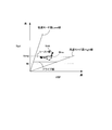
- FIG. 6 is a diagram illustrating a change in the input rotation speed when the first embodiment is used.
- FIG. 7 is a time chart showing the rotation speed limit control of the first embodiment.
- FIG. 8 is a diagram illustrating a modification of the first embodiment.
- FIG. 9 is a diagram illustrating a modification of the first embodiment.
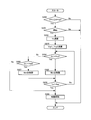
- FIG. 10 is a flowchart showing the rotation speed limit control of the second embodiment.
- the “speed ratio (speed stage)” of a transmission mechanism is a value obtained by dividing the input rotational speed of the transmission mechanism by the output rotational speed of the transmission mechanism. ) Is large, “Low”, and small is “High”. Further, changing the gear ratio (shift stage) to the Low side is referred to as downshift, and changing to the High side is referred to as upshift.
- FIG. 1 is a schematic configuration diagram of a vehicle according to an embodiment of the present invention.
- This vehicle includes an engine 1 as a drive source, and the output rotation of the engine 1 is input to a pump impeller 2a of a torque converter 2 with a lock-up clutch 2c, and from the turbine runner 2b to the first gear train 3, the transmission 4, the second It is transmitted to the drive wheel 7 via the gear train 5 and the actuator 6.
- the transmission 4 includes a mechanical oil pump 10 m that receives rotation of the engine 1 and is driven by using a part of the power of the engine 1, and an electric oil pump 10 e that is driven by receiving power supply from the battery 13. Is provided. Further, the transmission 4 is provided with a hydraulic control circuit 11 that regulates the hydraulic pressure generated by the oil discharged from the mechanical oil pump 10 m or the electric oil pump 10 e and supplies the hydraulic pressure to each part of the transmission 4.
- the transmission 4 includes a belt-type continuously variable transmission mechanism (hereinafter referred to as “variator 20”) as a friction transmission mechanism, and an auxiliary transmission mechanism 30 provided in series with the variator 20. “Provided in series” means that the variator 20 and the auxiliary transmission mechanism 30 are provided in series in the power transmission path from the engine 1 to the drive wheels 7.
- the auxiliary transmission mechanism 30 may be directly connected to the output shaft of the variator 20 as in this example, or may be connected via another transmission or power transmission mechanism (for example, a gear train).
- the variator 20 includes a primary pulley 21, a secondary pulley 22, and a V belt 23 that is wound around the pulleys 21 and 22.
- the width of the V groove changes according to the primary pulley pressure and the secondary pulley pressure, the contact radius between the V belt 23 and each pulley 21, 22 changes, and the actual gear ratio of the variator 20 is stepless. Change.
- the auxiliary transmission mechanism 30 is a transmission mechanism having two forward speeds and one reverse speed.
- the sub-transmission mechanism 30 is connected to a Ravigneaux type planetary gear mechanism 31 in which two planetary gear carriers are connected, and a plurality of friction elements connected to a plurality of rotating elements constituting the Ravigneaux type planetary gear mechanism 31 to change their linkage state.
- Fastening elements Low brake 32, High clutch 33, Rev brake 34
- the gear position of the auxiliary transmission mechanism 30 is changed.
- the gear position of the auxiliary transmission mechanism 30 is the first speed.
- the shift speed of the auxiliary transmission mechanism 30 is the second speed.
- the Rev brake 34 is engaged and the Low brake 32 and the High clutch 33 are released, the shift speed of the auxiliary transmission mechanism 30 is reverse.
- the gear ratio i of the entire transmission 4 is changed by changing the actual gear ratio of the variator 20 and the gear position of the auxiliary transmission mechanism 30.
- the controller 12 is a controller 12 that controls the engine 1 and the transmission 4 in an integrated manner. As shown in FIG. 2, the CPU 121, a storage device 122 including a RAM / ROM, an input interface 123, and an output interface 124 , And a bus 125 for interconnecting them.
- the input interface 123 includes an output signal of an accelerator pedal opening sensor 41 that detects an accelerator pedal opening APO that is an operation amount of the accelerator pedal 51, an output signal of a primary rotation speed sensor 42 that detects a primary pulley rotation speed Npri, a secondary An output signal of the secondary rotation speed sensor 43 that detects the pulley rotation speed Nsec, an output signal of the vehicle speed sensor 44 that detects the vehicle speed VSP, an output signal of the inhibitor switch 45 that detects the position of the shift lever 50, and the like are input.
- the storage device 122 stores a control program for the engine 1, a shift control program for the transmission 4, and various map tables used in these programs.
- the CPU 121 reads and executes a program stored in the storage device 122, performs various arithmetic processes on various signals input via the input interface 123, and performs fuel injection amount signal, ignition timing signal, throttle opening. A degree signal and a shift control signal are generated, and the generated signal is output to the engine 1 and the hydraulic control circuit 11 via the output interface 124.
- Various values used in the arithmetic processing by the CPU 121 and the arithmetic results are appropriately stored in the storage device 122.
- the hydraulic control circuit 11 includes a plurality of flow paths and a plurality of hydraulic control valves.
- the hydraulic pressure control circuit 11 controls a plurality of hydraulic pressure control valves based on a shift control signal from the controller 12 to switch the hydraulic pressure supply path, and the hydraulic pressure generated by the oil discharged from the mechanical oil pump 10m or the electric oil pump 10e.
- the necessary hydraulic pressure is prepared from the above and supplied to each part of the transmission 4. As a result, the actual gear ratio of the variator 20 and the gear position of the auxiliary transmission mechanism 30 are changed, and the transmission 4 is shifted.
- Shift of the transmission 4 is executed based on the shift map shown in FIG.
- the operating point of the transmission 4 is defined by the vehicle speed VSP and the primary pulley rotation speed Npri.
- the slope of the line connecting the operating point of the transmission 4 and the zero point of the lower left corner of the transmission map is the transmission ratio i of the transmission 4 (the overall transmission ratio obtained by multiplying the transmission ratio of the variator 20 by the transmission ratio of the subtransmission mechanism 30).
- a shift line is set for each accelerator pedal opening APO, and the shift of the transmission 4 is performed according to the shift line selected according to the accelerator pedal opening APO.
- the transmission 4 has a low speed mode lowest line in which the auxiliary transmission mechanism 30 is at the first speed and the transmission ratio of the variator 20 is at the lowest level, and the auxiliary transmission mechanism 30 is at the second speed and the transmission ratio of the variator 20 is at the highest.
- the gear ratio can be changed between the high-speed mode and the highest line.
- a coordinated shift is performed in which the gear ratio of the variator 20 is changed in the reverse direction.
- the coast line and the drive line coincide with the low-speed mode lowest line in the low vehicle speed region and coincide with the high-speed mode highest line in the high vehicle speed region.
- the primary pulley rotational speed Npri in the coast line is set higher than the primary pulley rotational speed Npri in the drive line.
- the target input rotational speed Nint of the primary pulley 21 is set to a value on the coast line (first target input rotational speed) after being set to a value on the drive line (second target input rotational speed). Rotation speed).
- the variator 20 controls the hydraulic pressure supplied to the primary pulley 21 and the secondary pulley 22 so that the actual input rotation speed Nina of the primary pulley 21 follows the target input rotation speed Nint, and changes the gear ratio.
- the actual input rotational speed Nina undershoots as shown by a broken line in FIG. 4 with respect to the target input rotational speed Nint due to a response delay due to a time constant in hydraulic control, an operation delay, or the like.
- the lock-up clutch 2c provided in the torque converter 2 is fastened except for conditions such as extremely low vehicle speed in order to improve the power transmission efficiency from the engine 1 to the drive wheels 7.
- the rotation speed of the engine 1 becomes lower than the release rotation speed
- the lockup clutch 2c is released to prevent the engine 1 from stalling. Therefore, the coast line and the drive line described above have a rotational speed Nr that releases the lock-up clutch 2c as shown in FIG. 4 so that the lock-up clutch 2c is not released until the vehicle speed VSP becomes extremely low.
- the primary pulley rotation speed Npri is set on the high rotation speed side. In FIG. 4, the release rotational speed Nr is converted into the rotational speed input to the primary pulley 21 in consideration of the gear ratio of the first gear train 3.
- fuel cut control is executed to stop fuel injection to the engine 1 with the lock-up clutch 2c engaged.
- the lockup clutch 2c is released and the fuel cut control is stopped.
- the fuel injection to the engine 1 is resumed. Thereby, the fuel injection to the engine 1 can be restarted without using the starter motor or the like and without stalling the engine 1.
- FIG. 5 is a flowchart for explaining the rotation speed limit control of this embodiment.
- step S100 the controller 12 determines whether or not the accelerator pedal opening APO is equal to or smaller than the second predetermined opening APOp2.
- the second predetermined opening APOp2 is an opening that is slightly larger than the first predetermined opening APOp1 serving as a drive line, and is set in advance. If the accelerator pedal opening APO is equal to or smaller than the second predetermined opening APOp2, the process proceeds to step S101. If the accelerator pedal opening APO is larger than the second predetermined opening APOp2, the current process ends.
- step S101 the controller 12 determines whether or not the lockup clutch 2c is engaged. If the lock-up clutch 2c is engaged, the process proceeds to step S102. If the lock-up clutch 2c is released, the current process ends.
- step S102 the controller 12 calculates a closing speed Vc that is a return operation speed of the accelerator pedal opening APO. For example, the controller 12 calculates the closing speed Vc of the accelerator pedal opening APO from the current accelerator pedal opening APO and the accelerator pedal opening APO at the previous processing.
- step S103 the controller 12 calculates a predetermined closing speed Vcp. Specifically, the controller 12 calculates a predetermined closing speed Vcp by dividing the current accelerator pedal opening APO by a predetermined time Tp.
- the predetermined time Tp is a delay time until a change in the actual input rotation speed Nina appears with respect to a change in the target input rotation speed Nint, and is set in advance from a response delay due to a time constant in hydraulic control, an operation delay, or the like. .
- step S104 the controller 12 determines whether or not the closing speed Vc of the accelerator pedal opening APO is larger than a predetermined closing speed Vcp.
- the accelerator pedal opening APO is smaller than the second predetermined opening APOp2, and when the closing speed Vc of the accelerator pedal opening APO is larger than the predetermined closing speed Vcp, the controller 12 opens the accelerator pedal. It is determined that the degree APO is equal to or less than the first predetermined opening APOp1 and the accelerator pedal opening APO becomes zero during the predetermined time Tp.
- the controller 12 determines.
- the controller 12 sets the target input rotational speed Nint according to the accelerator pedal opening APO, and the actual input due to undershoot. It is determined that the rotational speed Nina is lower than the release rotational speed Nr. If the actual input rotational speed Nina becomes lower than the release rotational speed Nr due to undershoot, the process proceeds to step S105. If the actual input rotational speed Nina does not become lower than the release rotational speed Nr due to undershoot, the process proceeds to step S105. The process proceeds to S107.
- step S105 the controller 12 limits the target input rotation speed Nint. Specifically, the controller 12 sets the target input rotation speed Nint to a predetermined target input rotation speed Nintp (third target input rotation speed).
- the predetermined target input rotational speed Nintp is a value obtained by adding a deviation between the primary pulley rotational speed Npri and the release rotational speed Nr in the drive line to the primary pulley rotational speed Npri in the drive line.
- the predetermined target input rotation speed Nintp is higher than the primary pulley rotation speed Npri on the drive line and lower than the primary pulley rotation speed Npri on the coast line.
- the accelerator pedal 51 is not depressed, and the target input rotational speed Nint does not decrease to the value on the drive line even when the operating point of the transmission 4 is changed to the coast line via the drive line.
- the predetermined target input rotational speed Nintp is reached, and the actual input rotational speed Nina changes following the predetermined target input rotational speed Nintp. Accordingly, the actual input rotation speed Nina is higher than when the target input rotation speed Nint is set to a value on the drive line, and the actual input rotation speed Nina is lower than the release rotation speed Nr as shown in FIG. There is no.
- the gear ratio i of the transmission 4 is changed based on the predetermined target input rotational speed Nintp and the vehicle speed VSP.
- step S106 the controller 12 determines whether or not a predetermined end condition is satisfied. Specifically, the controller 12 determines whether or not the elapsed time Te after the target input rotation speed Nint is set to the predetermined target input rotation speed Nintp has reached the predetermined elapsed time Tep.
- the predetermined elapsed time Tep is a maximum time until the undershooted actual input rotational speed Nina switches from a decrease to an increase, and is set in advance. The undershoot amount changes according to the return operation of the accelerator pedal 51.
- the predetermined elapsed time Tep is set as the maximum time for the return operation of the accelerator pedal 51, that is, the undershoot amount, and the actual input rotational speed Nina is prevented from becoming lower than the release rotational speed Nr.
- the process returns to step S105 until the elapsed time Te reaches the predetermined elapsed time Tep, and when the elapsed time Te reaches the predetermined elapsed time Tep, the process proceeds to step S107.
- step S107 the controller 12 releases the restriction on the target input rotation speed Nint.
- the gear ratio i of the transmission 4 is changed according to the shift line corresponding to the accelerator pedal opening APO. For example, when the accelerator pedal opening APO is zero, the target input rotational speed Nint is set to a value on the coast line, and the gear ratio i of the transmission 4 is changed.
- the accelerator pedal opening APO is the first predetermined opening APOp1
- the target input rotational speed Nint is set to a value on the drive line, and the gear ratio i of the transmission 4 is changed.
- the accelerator pedal opening APO becomes lower than the second predetermined opening APOp2, and it is determined that the closing speed Vc of the accelerator pedal opening APO is larger than the predetermined closing speed Vcp.
- the target input rotation speed Nint is limited and set to the predetermined target input rotation speed Nintp.
- the target input rotation speed Nint is set to a value higher than the primary pulley rotation speed Npri in the drive line by a difference between the primary pulley rotation speed Npri in the drive line and the release rotation speed Nr. Even in such a case, the actual input rotation speed Nina undershoots the target input rotation speed Nint, but the actual input rotation speed Nina does not become lower than the release rotation speed Nr.
- the actual speed ratio ia corresponding to the actual input rotational speed Nina is higher than the target speed ratio it corresponding to the target input rotational speed Nint due to undershoot.
- the restriction on the target input rotation speed Nint is released at a time t1 when the predetermined elapsed time Tep has elapsed since the target input rotation speed Nint was limited to the predetermined target input rotation speed Nintp.
- the target input rotational speed Nint is changed to a value on the coast line corresponding to the accelerator pedal opening APO. Further, the target speed ratio it and the actual speed ratio ia are changed to the Low side.
- the primary pulley 21 The target input rotation speed Nint is set to a predetermined target input rotation speed Nintp that is higher than the value on the drive line.
- the target input rotational speed Nint is set to the predetermined target input rotational speed Nintp. Set. Thereby, it is possible to suppress the actual input rotation speed Nina from becoming lower than the release rotation speed Nr due to undershoot, and to suppress a reduction in fuel consumption of the engine 1.
- the target input rotational speed Nint is set according to the return operation of the accelerator pedal 51, and the transmission according to the target input rotational speed Nint. 4 can be changed.
- the target input rotation speed Nint is limited to the predetermined target input rotation speed Nintp, for example, although the accelerator pedal opening APO is zero, the operating point of the transmission 4 is not on the coast line. There is a risk of discomfort. In the present embodiment, it is possible to suppress giving the driver such a sense of discomfort while suppressing a decrease in fuel consumption of the engine 1.
- the predetermined target input rotation speed Nintp is set by adding the difference between the primary pulley rotation speed Npri and the release rotation speed Nr in the drive line to the primary pulley rotation speed Npri in the drive line. Thereby, it is possible to prevent the predetermined target input rotation speed Nintp from increasing.
- the target input rotational speed Nint is set to the predetermined target input rotational speed Nintp, when the rotational speed limit control is terminated in a state where the operating point of the transmission 4 based on the accelerator pedal opening APO is a drive line.
- the target input rotational speed Nint is changed to a value on the drive line.
- the predetermined target input rotational speed Nintp when the predetermined target input rotational speed Nintp is high, the amount of change in the actual input rotational speed Nina, that is, the amount of change in the speed ratio i of the transmission 4 (upshift amount) increases. In such a case, since the driver does not operate the accelerator pedal 51, the driver may feel uncomfortable if the amount of change in the gear ratio i of the transmission 4 increases. In the present embodiment, by preventing the predetermined target input rotation speed Nintp from increasing, it is possible to suppress giving such a sense of discomfort to the driver.
- the predetermined target input rotational speed Nintp is set higher than the primary pulley rotational speed Npri on the drive line and lower than the primary pulley rotational speed Npri on the coast line.
- the rotational speed limit control is terminated, and the target input rotational speed Nint is set to a value corresponding to the accelerator pedal opening APO.
- the state where the operating point of the transmission 4 based on the accelerator pedal opening APO and the actual operating point of the transmission 4 do not coincide can be shortened, and the driver can be prevented from feeling uncomfortable. .
- the predetermined elapsed time Tep is the maximum time from when the target input rotation speed Nint is set to the predetermined target input rotation speed Nintp until the undershooted actual input rotation speed Nina switches from decrease to increase.
- the undershoot amount varies depending on the return operation of the accelerator pedal opening APO. In the present embodiment, by setting the predetermined end condition in this way, it is possible to prevent the actual input rotational speed Nina from becoming lower than the release rotational speed Nr regardless of the return operation of the accelerator pedal opening APO. .
- step S105 the setting method of the predetermined target input rotation speed Nintp in step S105 is different.
- the predetermined target input rotational speed Nintp in step S105 of the modified example is a drive line that represents the maximum difference between the release rotational speed Nr and the actual input rotational speed Nina when the actual input rotational speed Nina is lower than the release rotational speed Nr due to undershoot. Is set to a value added to the primary pulley rotation speed Npri. Such a maximum difference is calculated in advance through experiments or the like.
- the actual input rotational speed Nina does not become lower than the release rotational speed Nr. Therefore, the actual input rotation speed Nina can be prevented from becoming lower than the release rotation speed Nr, and the fuel consumption of the engine 1 can be prevented from being lowered.
- the predetermined target input rotational speed Nintp in step S105 is set to a value on the coast line.
- the target input rotation speed Nint is limited as shown in FIG. 9, and the actual input rotation speed Nina does not become lower than the release rotation speed Nr. Also in this modified example, the actual input rotation speed Nina can be prevented from becoming lower than the release rotation speed Nr, and the fuel consumption of the engine 1 can be prevented from decreasing. Further, when the accelerator pedal opening APO is zero when the rotation speed limit control is finished, the amount of change in the actual input rotation speed Nina is small, and the uncomfortable feeling given to the driver can be suppressed.
- Rotational speed limit control is different in the second embodiment, and the rotational speed limit control of the second embodiment will be described with reference to the flowchart of FIG.
- step S200 to step S202 Since the processing from step S200 to step S202 is the same as that of the first embodiment, description thereof is omitted here.
- step S203 the controller 12 calculates a first predetermined closing speed Vcp1 and a second predetermined closing speed Vcp2.
- the first predetermined closing speed Vcp1 is calculated by dividing the current accelerator pedal opening APO by the first predetermined time Tp1.
- the second predetermined closing speed Vcp2 is calculated by dividing the current accelerator pedal opening APO by the second predetermined time Tp2.
- the first predetermined time Tp1 is a delay time until the change of the actual input rotation speed Nina is started with respect to the change of the target input rotation speed Nint. Is set.
- the second predetermined time Tp2 is set to have a longer delay time than the first predetermined time Tp1, and the first predetermined closing speed Vcp1 is set to be larger than the second predetermined closing speed Vcp2.
- step S204 the controller 12 determines whether or not the closing speed Vc of the accelerator pedal opening APO is larger than the first predetermined closing speed Vcp1. If the closing speed Vc of the accelerator pedal opening APO is larger than the first predetermined closing speed Vcp1, the process proceeds to step S206, and if the closing speed Vc of the accelerator pedal opening APO is equal to or lower than the first predetermined closing speed Vcp1. The process proceeds to step S205.
- step S205 it is determined whether or not the closing speed Vc of the accelerator pedal opening APO is larger than the second predetermined closing speed Vcp2.
- the process proceeds to step S207, and when the closing speed Vc of the accelerator pedal opening APO is equal to or lower than the first predetermined closing speed Vcp1.
- the process proceeds to step S209.
- the undershoot amount of the actual input rotational speed Nina with respect to the target input rotational speed Nint changes according to the closing speed Vc of the accelerator pedal opening APO. Therefore, in the present embodiment, the subsequent processing is changed according to the closing speed Vc of the accelerator pedal opening APO.
- step S206 the controller 12 limits the target input rotation speed Nint and sets the target input rotation speed Nint to the first predetermined target input rotation speed Nintp1.
- the first predetermined target input rotation speed Nintp1 is a value on the coast line.
- step S207 the controller 12 limits the target input rotation speed Nint and sets the target input rotation speed Nint to the second predetermined target input rotation speed Nintp2.
- the second predetermined target input rotation speed Nintp2 is the same value as the predetermined target input rotation speed Nintp of the first embodiment.
- step S206 The target input rotational speed Nint is limited to the first predetermined target input rotational speed Nintp1 that is a value on the coast line that is sufficiently higher than the primary pulley rotational speed Npri in the drive line.
- the closing speed Vc of the accelerator pedal opening APO is smaller than the first predetermined closing speed Vcp1 but larger than the second predetermined closing speed Vcp2
- the closing speed Vc of the accelerator pedal opening APO is the first predetermined closing speed Vcp1.
- the target input rotational speed Nint is a value obtained by adding the deviation between the primary pulley rotational speed Npri and the release rotational speed Nr on the drive line to the primary pulley rotational speed Npri on the drive line. Limited to speed Nintp2.
- step S208 the controller 12 determines whether or not a predetermined end condition is satisfied. Specifically, the controller 12 determines whether the elapsed time Te after the target input rotational speed Nint is set to the first predetermined target input rotational speed Nintp1 or the second predetermined target input rotational speed Nintp2 becomes the predetermined elapsed time Tep. Judge whether. The process returns to step S204 until the elapsed time Te reaches the predetermined elapsed time Tep, and the process proceeds to step S209 when the elapsed time Te reaches the predetermined elapsed time Tep.
- step S209 the controller 12 releases the restriction on the target input rotation speed Nint. Thereby, the gear ratio i of the transmission 4 is changed according to the shift line corresponding to the accelerator pedal opening APO.
- the target input rotational speed Nint is set to the first predetermined target input rotational speed Nintp1 or the second predetermined target input rotational speed Nintp2 according to the closing speed Vc of the accelerator pedal opening APO. This prevents the actual input rotation speed Nina from becoming lower than the release rotation speed Nr.
- the closing speed Vc of the accelerator pedal opening APO is small, the actual input rotation speed Nina is set when the rotation speed limit control is terminated. The amount of change can be reduced, and the uncomfortable feeling given to the driver can be suppressed.
- the target input rotation speed Nint is set to the second predetermined target input rotation speed.
- the first predetermined target input rotational speed Nintp1 that is larger than Nintp2 is set.
- the closing speed Vc of the accelerator pedal opening APO is not so large, that is, the closing speed Vc of the accelerator pedal opening APO is equal to or lower than the first predetermined closing speed Vcp1, and the closing speed Vc of the accelerator pedal opening APO is the second.
- the target input rotation speed Nint is set to the second predetermined target input rotation speed Nintp2.
- the rotational speed limit control is terminated, and the amount of change in the actual input rotational speed Nina can be reduced when the operating point of the transmission 4 is set to the drive line, thereby suppressing the uncomfortable feeling given to the driver. it can.
- the first predetermined target input rotational speed Nintp1 and the second predetermined target input rotational speed Nintp2 are not limited to the above combinations.
- the first predetermined target input rotational speed Nintp1 is an actual input rotational speed Nina by undershooting. May be a value obtained by adding the maximum difference between the release rotational speed Nr and the actual input rotational speed Nina to the primary pulley rotational speed Npri in the drive line when is lower than the release rotational speed Nr.
- the target input rotation speed Nint may be a variable corresponding to the closing speed Vc of the accelerator pedal opening APO. This prevents the actual input rotation speed Nina from becoming lower than the release rotation speed Nr, and also makes it possible to reduce the amount of change in the actual input rotation speed Nina when the rotation speed limit control is finished, giving the driver a sense of incongruity. Can be suppressed.
- the vehicle having the torque converter 2 has been described.
- the Low brake 32 or the High clutch 33 may be released as a friction engagement element.
- a clutch constituting the forward / reverse switching mechanism may be released.
- the rotational speed limit control of this embodiment may be executed.
- the target input rotational speed Nint is limited to a predetermined input rotational speed (including the first input predetermined rotational speed and the second input predetermined rotational speed) according to the closing speed Vc of the accelerator pedal opening APO. Although it determined, you may determine according to the fall speed of the target input rotational speed Nint. This also makes it possible to determine with a simple configuration. Further, the determination may be made according to the closing speed Vc and the decreasing speed.
- the predetermined elapsed time Tep as the predetermined end condition is a fixed value, but may be variable. Specifically, the predetermined elapsed time Tep is shortened as the closing speed Vc of the accelerator pedal opening APO is smaller. When the closing speed Vc of the accelerator pedal opening APO is reduced, the undershoot amount is reduced. For this reason, the smaller the closing speed Vc of the accelerator pedal opening APO, the shorter the predetermined elapsed time Tep, thereby shortening the time during which the operating point of the transmission 4 deviates from the accelerator pedal opening APO, giving the driver a sense of discomfort. Can be suppressed.
Abstract
Description
Claims (13)
- エンジンと駆動輪との間に設けた無段変速機と、
前記無段変速機に直列に配置され、前記エンジンの回転速度が解放回転速度よりも低くなると解放される摩擦締結要素とを備える車両を制御する車両の制御装置であって、
アクセルペダル開度がゼロの場合に設定される前記無段変速機の第1目標入力回転速度が、前記アクセルペダル開度がゼロよりも大きい所定開度の場合に設定される前記無段変速機の第2目標入力回転速度よりも高く設定された変速マップに基づいて前記無段変速機の変速比を制御する制御手段を備え、
前記制御手段は、前記アクセルペダル開度が前記所定開度以下となるアクセルペダル操作が行われる場合、前記無段変速機の目標入力回転速度を前記第2目標入力回転速度よりも高い第3目標入力回転速度に設定する、
車両の制御装置。 A continuously variable transmission provided between the engine and the drive wheel;
A vehicle control device that controls a vehicle that is arranged in series with the continuously variable transmission and that includes a frictional engagement element that is released when a rotational speed of the engine is lower than a release rotational speed;
The continuously variable transmission that is set when the first target input rotational speed of the continuously variable transmission that is set when the accelerator pedal opening is zero is a predetermined opening that is greater than zero. Control means for controlling the gear ratio of the continuously variable transmission based on a shift map set higher than the second target input rotational speed of
When the accelerator pedal operation is performed such that the accelerator pedal opening is equal to or less than the predetermined opening, the control means sets a target input rotational speed of the continuously variable transmission to a third target higher than the second target input rotational speed. Set the input rotation speed,
Vehicle control device. - 請求項1に記載の車両の制御装置であって、
前記制御手段は、前記アクセルペダル開度が前記所定開度以下となるアクセルペダル操作が行われ、前記エンジンの回転速度が前記解放回転速度よりも低くなる場合、前記無段変速機の目標入力回転速度を前記第3目標入力回転速度に設定する、
車両の制御装置。 The vehicle control device according to claim 1,
The control means performs a target input rotation of the continuously variable transmission when an accelerator pedal operation is performed so that the accelerator pedal opening is equal to or less than the predetermined opening, and the rotational speed of the engine is lower than the release rotational speed. Setting the speed to the third target input rotation speed;
Vehicle control device. - 請求項2に記載の車両の制御装置であって、
前記制御手段は、アクセルペダルの戻し操作速度が所定操作速度よりも大きい場合、前記エンジンの回転速度が前記解放回転速度よりも低くなる、と判断する、
車両の制御装置。 The vehicle control device according to claim 2,
The control means determines that the rotational speed of the engine is lower than the release rotational speed when a return operation speed of the accelerator pedal is higher than a predetermined operation speed.
Vehicle control device. - 請求項2または3に記載の車両の制御装置であって、
前記制御手段は、前記無段変速機の目標入力回転速度の低下速度が所定低下速度よりも大きい場合、前記エンジンの回転速度が前記解放回転速度よりも低くなる、と判断する、
車両の制御装置。 The vehicle control device according to claim 2 or 3,
The control means determines that the rotational speed of the engine is lower than the release rotational speed when the target input rotational speed decreasing speed of the continuously variable transmission is greater than a predetermined decreasing speed.
Vehicle control device. - 請求項1から4のいずれか1つに記載の車両の制御装置であって、
前記第3目標入力回転速度は、前記第2目標入力回転速度と前記解放回転速度との差分を、前記第2目標入力回転速度に加算して設定される、
車両の制御装置。 The vehicle control device according to any one of claims 1 to 4, comprising:
The third target input rotation speed is set by adding a difference between the second target input rotation speed and the release rotation speed to the second target input rotation speed.
Vehicle control device. - 請求項5に記載の車両の制御装置であって、
前記第3目標入力回転速度は、前記第2目標入力回転速度よりも高く、かつ前記第1目標入力回転速度よりも低い、
車両の制御装置。 The vehicle control device according to claim 5,
The third target input rotation speed is higher than the second target input rotation speed and lower than the first target input rotation speed;
Vehicle control device. - 請求項1から4のいずれか1つに記載の車両の制御装置であって、
前記第3目標入力回転速度は、前記無段変速機の実入力回転速度が前記解放回転速度よりも低くなる場合における前記第2目標入力回転速度と前記実入力回転速度との最大差分を、前記第2目標入力回転速度に加算して設定される、
車両の制御装置。 The vehicle control device according to any one of claims 1 to 4, comprising:
The third target input rotation speed is a maximum difference between the second target input rotation speed and the actual input rotation speed when the actual input rotation speed of the continuously variable transmission is lower than the release rotation speed. Set by adding to the second target input rotation speed,
Vehicle control device. - 請求項1から4のいずれか1つに記載の車両の制御装置であって、
前記第3目標入力回転速度は、前記第1目標入力回転速度に設定される、
車両の制御装置。 The vehicle control device according to any one of claims 1 to 4, comprising:
The third target input rotation speed is set to the first target input rotation speed;
Vehicle control device. - 請求項1から8のいずれか1つに記載の車両の制御装置であって、
前記制御手段は、アクセルペダルの戻し操作速度、または前記無段変速機の目標入力回転速度の低下速度に応じて、前記第3目標入力回転速度を設定する、
車両の制御装置。 The vehicle control device according to any one of claims 1 to 8,
The control means sets the third target input rotation speed according to a return operation speed of an accelerator pedal or a decrease speed of a target input rotation speed of the continuously variable transmission.
Vehicle control device. - 請求項9に記載の車両の制御装置であって、
前記第3目標入力回転速度は、前記アクセルペダルの戻し操作速度、または前記無段変速機の目標入力速度の低下速度が大きいほど、高い、
車両の制御装置。 The vehicle control device according to claim 9, comprising:
The third target input rotation speed is higher as the return operation speed of the accelerator pedal or the lowering speed of the target input speed of the continuously variable transmission is larger.
Vehicle control device. - 請求項1から10のいずれか1つに記載の車両の制御装置であって、
前記制御手段は、所定終了条件が成立すると、前記無段変速機の目標入力回転速度を前記アクセルペダル開度に応じた入力回転速度に設定する、
車両の制御装置。 A vehicle control device according to any one of claims 1 to 10,
The control means sets a target input rotation speed of the continuously variable transmission to an input rotation speed corresponding to the accelerator pedal opening when a predetermined end condition is satisfied.
Vehicle control device. - 請求項11に記載の車両の制御装置であって、
前記制御手段は、前記無段変速機の目標入力回転速度を前記第3目標入力回転速度に設定してから所定経過時間が経過すると、前記所定終了条件が成立する、と判断し、
前記所定経過時間は、前記無段変速機の目標入力回転速度を前記第3目標入力回転速度に設定してから、前記無段変速機の実回転速度が増加するまでの最大時間である、
車両の制御装置。 The vehicle control device according to claim 11,
The control means determines that the predetermined end condition is satisfied when a predetermined elapsed time has elapsed since the target input rotational speed of the continuously variable transmission was set to the third target input rotational speed;
The predetermined elapsed time is a maximum time from when the target input rotational speed of the continuously variable transmission is set to the third target input rotational speed until the actual rotational speed of the continuously variable transmission increases.
Vehicle control device. - エンジンと駆動輪との間に設けた無段変速機と、
前記無段変速機に直列に配置され、前記エンジンの回転速度が解放回転速度よりも低くなると解放される摩擦締結要素とを備える変速機を制御する車両の制御方法であって、
アクセルペダル開度がゼロの場合に設定される前記無段変速機の第1目標入力回転速度が、前記アクセルペダル開度がゼロよりも大きい所定開度の場合に設定される前記無段変速機の第2目標入力回転速度よりも高く設定された変速マップに基づいて前記無段変速機の変速比を制御し、
前記アクセルペダル開度が前記所定開度以下となるアクセルペダル操作が行われる場合、前記無段変速機の目標入力回転速度を前記第2目標入力回転速度よりも高い第3目標入力回転速度に設定する、
車両の制御方法。 A continuously variable transmission provided between the engine and the drive wheel;
A vehicle control method for controlling a transmission that is arranged in series with the continuously variable transmission and that includes a frictional engagement element that is released when a rotational speed of the engine is lower than a release rotational speed,
The continuously variable transmission that is set when the first target input rotational speed of the continuously variable transmission that is set when the accelerator pedal opening is zero is a predetermined opening that is greater than zero. The transmission ratio of the continuously variable transmission is controlled based on a shift map set higher than the second target input rotational speed of
When the accelerator pedal operation is performed so that the accelerator pedal opening is equal to or less than the predetermined opening, the target input rotation speed of the continuously variable transmission is set to a third target input rotation speed higher than the second target input rotation speed. To
Vehicle control method.
Priority Applications (5)
| Application Number | Priority Date | Filing Date | Title |
|---|---|---|---|
| US15/575,960 US10267418B2 (en) | 2015-05-22 | 2016-05-18 | Vehicle control device and vehicle control method |
| CN201680029089.1A CN107614941B (en) | 2015-05-22 | 2016-05-18 | The control device and its control method of vehicle |
| KR1020177035738A KR102016830B1 (en) | 2015-05-22 | 2016-05-18 | Vehicle control device, and control method thereof |
| EP16799901.0A EP3299677B1 (en) | 2015-05-22 | 2016-05-18 | Vehicle control device and method for controlling same |
| JP2017520652A JP6502489B2 (en) | 2015-05-22 | 2016-05-18 | Control device of vehicle and control method thereof |
Applications Claiming Priority (2)
| Application Number | Priority Date | Filing Date | Title |
|---|---|---|---|
| JP2015-104176 | 2015-05-22 | ||
| JP2015104176 | 2015-05-22 |
Publications (1)
| Publication Number | Publication Date |
|---|---|
| WO2016190195A1 true WO2016190195A1 (en) | 2016-12-01 |
Family
ID=57393366
Family Applications (1)
| Application Number | Title | Priority Date | Filing Date |
|---|---|---|---|
| PCT/JP2016/064763 WO2016190195A1 (en) | 2015-05-22 | 2016-05-18 | Vehicle control device and method for controlling same |
Country Status (6)
| Country | Link |
|---|---|
| US (1) | US10267418B2 (en) |
| EP (1) | EP3299677B1 (en) |
| JP (1) | JP6502489B2 (en) |
| KR (1) | KR102016830B1 (en) |
| CN (1) | CN107614941B (en) |
| WO (1) | WO2016190195A1 (en) |
Families Citing this family (2)
| Publication number | Priority date | Publication date | Assignee | Title |
|---|---|---|---|---|
| WO2019146475A1 (en) * | 2018-01-23 | 2019-08-01 | ジヤトコ株式会社 | Lock-up disengagement control device for automatic transmission |
| CN113446396B (en) * | 2021-09-02 | 2022-01-04 | 盛瑞传动股份有限公司 | Gear shifting control method, gear shifting control device and storage medium |
Citations (3)
| Publication number | Priority date | Publication date | Assignee | Title |
|---|---|---|---|---|
| JP2003090427A (en) * | 2001-09-17 | 2003-03-28 | Jatco Ltd | Lock up control system for automatic transmission |
| JP2010078124A (en) * | 2008-09-29 | 2010-04-08 | Nissan Motor Co Ltd | Coasting travel control device for vehicle |
| JP2010209982A (en) * | 2009-03-09 | 2010-09-24 | Nissan Motor Co Ltd | Shift speed control device for automatic transmission for vehicle |
Family Cites Families (8)
| Publication number | Priority date | Publication date | Assignee | Title |
|---|---|---|---|---|
| EP0238310B1 (en) * | 1986-03-17 | 1991-07-17 | Isuzu Motors Limited | Apparatus for controlling an automatic gear transmission |
| JP5769615B2 (en) * | 2011-12-26 | 2015-08-26 | ジヤトコ株式会社 | Shift control device for continuously variable transmission |
| JP5743876B2 (en) * | 2011-12-26 | 2015-07-01 | ジヤトコ株式会社 | Shift control device for continuously variable transmission |
| JP6069519B2 (en) * | 2013-10-31 | 2017-02-01 | ジヤトコ株式会社 | Control device for lock-up clutch |
| CN107407404B (en) * | 2015-03-23 | 2019-06-07 | 加特可株式会社 | The control device and its control method of stepless transmission |
| KR101992069B1 (en) * | 2015-06-23 | 2019-06-21 | 쟈트코 가부시키가이샤 | Transmission & Transmission Control Methods |
| JP6233379B2 (en) * | 2015-10-15 | 2017-11-22 | トヨタ自動車株式会社 | Control device for automatic transmission |
| JP6350583B2 (en) * | 2016-04-15 | 2018-07-04 | トヨタ自動車株式会社 | Vehicle control device |
-
2016
- 2016-05-18 CN CN201680029089.1A patent/CN107614941B/en active Active
- 2016-05-18 EP EP16799901.0A patent/EP3299677B1/en active Active
- 2016-05-18 US US15/575,960 patent/US10267418B2/en active Active
- 2016-05-18 KR KR1020177035738A patent/KR102016830B1/en active IP Right Grant
- 2016-05-18 JP JP2017520652A patent/JP6502489B2/en active Active
- 2016-05-18 WO PCT/JP2016/064763 patent/WO2016190195A1/en active Application Filing
Patent Citations (3)
| Publication number | Priority date | Publication date | Assignee | Title |
|---|---|---|---|---|
| JP2003090427A (en) * | 2001-09-17 | 2003-03-28 | Jatco Ltd | Lock up control system for automatic transmission |
| JP2010078124A (en) * | 2008-09-29 | 2010-04-08 | Nissan Motor Co Ltd | Coasting travel control device for vehicle |
| JP2010209982A (en) * | 2009-03-09 | 2010-09-24 | Nissan Motor Co Ltd | Shift speed control device for automatic transmission for vehicle |
Also Published As
| Publication number | Publication date |
|---|---|
| EP3299677B1 (en) | 2020-02-26 |
| JPWO2016190195A1 (en) | 2018-03-01 |
| CN107614941A (en) | 2018-01-19 |
| EP3299677A4 (en) | 2018-06-06 |
| US20180172149A1 (en) | 2018-06-21 |
| KR20180008574A (en) | 2018-01-24 |
| KR102016830B1 (en) | 2019-08-30 |
| JP6502489B2 (en) | 2019-04-17 |
| EP3299677A1 (en) | 2018-03-28 |
| CN107614941B (en) | 2019-12-03 |
| US10267418B2 (en) | 2019-04-23 |
Similar Documents
| Publication | Publication Date | Title |
|---|---|---|
| KR101647513B1 (en) | Continuously variable transmission and method of controlling the same | |
| JP5548599B2 (en) | Coast stop vehicle and control method thereof | |
| JP5080627B2 (en) | Continuously variable transmission and shift control method | |
| JP4790834B2 (en) | Control device for continuously variable transmission for vehicle | |
| JP5646941B2 (en) | Coast stop vehicle | |
| US9421978B2 (en) | Continuously variable transmission and control method therefor | |
| JP6437125B2 (en) | Hydraulic control device and hydraulic control method for continuously variable transmission for vehicle | |
| JP5718530B2 (en) | Automatic transmission for vehicles | |
| WO2016190195A1 (en) | Vehicle control device and method for controlling same | |
| KR101828724B1 (en) | Control device for continuously variable transmission equipped with auxiliary transmission | |
| JP6450463B2 (en) | Vehicle control apparatus and vehicle control method | |
| JP6547010B2 (en) | Control device of vehicle and control method of vehicle | |
| KR101624472B1 (en) | Automatic transmission for vehicle | |
| JP2017137945A (en) | Vehicle control device and vehicle control method | |
| JP6653961B2 (en) | Control device for automatic transmission | |
| WO2016152327A1 (en) | Control device for continuously variable transmission and control method therefor | |
| JP5977271B2 (en) | Continuously variable transmission and control method thereof | |
| JP6633920B2 (en) | Vehicle control device and vehicle control method | |
| JP2019100473A (en) | Lock-up clutch controller of vehicle | |
| JP2017078474A (en) | Control device of automatic transmission and control method of automatic transmission | |
| JP6752506B2 (en) | Control device for continuously variable transmission for vehicles | |
| JP6660122B2 (en) | Vehicle control device and vehicle control method | |
| WO2013132899A1 (en) | Speed-change control apparatus and speed-change control method for continuously variable transmission |
Legal Events
| Date | Code | Title | Description |
|---|---|---|---|
| 121 | Ep: the epo has been informed by wipo that ep was designated in this application |
Ref document number: 16799901 Country of ref document: EP Kind code of ref document: A1 |
|
| ENP | Entry into the national phase |
Ref document number: 2017520652 Country of ref document: JP Kind code of ref document: A |
|
| WWE | Wipo information: entry into national phase |
Ref document number: 15575960 Country of ref document: US |
|
| NENP | Non-entry into the national phase |
Ref country code: DE |
|
| ENP | Entry into the national phase |
Ref document number: 20177035738 Country of ref document: KR Kind code of ref document: A |
|
| WWE | Wipo information: entry into national phase |
Ref document number: 2016799901 Country of ref document: EP |