WO2016189808A1 - 測距撮像装置、その測距方法及び固体撮像装置 - Google Patents
測距撮像装置、その測距方法及び固体撮像装置 Download PDFInfo
- Publication number
- WO2016189808A1 WO2016189808A1 PCT/JP2016/002297 JP2016002297W WO2016189808A1 WO 2016189808 A1 WO2016189808 A1 WO 2016189808A1 JP 2016002297 W JP2016002297 W JP 2016002297W WO 2016189808 A1 WO2016189808 A1 WO 2016189808A1
- Authority
- WO
- WIPO (PCT)
- Prior art keywords
- signal
- exposure
- light
- unit
- distance
- Prior art date
- Legal status (The legal status is an assumption and is not a legal conclusion. Google has not performed a legal analysis and makes no representation as to the accuracy of the status listed.)
- Ceased
Links
Images






Classifications
-
- H—ELECTRICITY
- H10—SEMICONDUCTOR DEVICES; ELECTRIC SOLID-STATE DEVICES NOT OTHERWISE PROVIDED FOR
- H10F—INORGANIC SEMICONDUCTOR DEVICES SENSITIVE TO INFRARED RADIATION, LIGHT, ELECTROMAGNETIC RADIATION OF SHORTER WAVELENGTH OR CORPUSCULAR RADIATION
- H10F39/00—Integrated devices, or assemblies of multiple devices, comprising at least one element covered by group H10F30/00, e.g. radiation detectors comprising photodiode arrays
- H10F39/80—Constructional details of image sensors
- H10F39/803—Pixels having integrated switching, control, storage or amplification elements
-
- G—PHYSICS
- G01—MEASURING; TESTING
- G01C—MEASURING DISTANCES, LEVELS OR BEARINGS; SURVEYING; NAVIGATION; GYROSCOPIC INSTRUMENTS; PHOTOGRAMMETRY OR VIDEOGRAMMETRY
- G01C3/00—Measuring distances in line of sight; Optical rangefinders
- G01C3/02—Details
- G01C3/06—Use of electric means to obtain final indication
-
- G—PHYSICS
- G01—MEASURING; TESTING
- G01S—RADIO DIRECTION-FINDING; RADIO NAVIGATION; DETERMINING DISTANCE OR VELOCITY BY USE OF RADIO WAVES; LOCATING OR PRESENCE-DETECTING BY USE OF THE REFLECTION OR RERADIATION OF RADIO WAVES; ANALOGOUS ARRANGEMENTS USING OTHER WAVES
- G01S17/00—Systems using the reflection or reradiation of electromagnetic waves other than radio waves, e.g. lidar systems
- G01S17/02—Systems using the reflection of electromagnetic waves other than radio waves
- G01S17/06—Systems determining position data of a target
- G01S17/08—Systems determining position data of a target for measuring distance only
- G01S17/10—Systems determining position data of a target for measuring distance only using transmission of interrupted, pulse-modulated waves
-
- G—PHYSICS
- G01—MEASURING; TESTING
- G01S—RADIO DIRECTION-FINDING; RADIO NAVIGATION; DETERMINING DISTANCE OR VELOCITY BY USE OF RADIO WAVES; LOCATING OR PRESENCE-DETECTING BY USE OF THE REFLECTION OR RERADIATION OF RADIO WAVES; ANALOGOUS ARRANGEMENTS USING OTHER WAVES
- G01S17/00—Systems using the reflection or reradiation of electromagnetic waves other than radio waves, e.g. lidar systems
- G01S17/88—Lidar systems specially adapted for specific applications
- G01S17/89—Lidar systems specially adapted for specific applications for mapping or imaging
-
- G—PHYSICS
- G01—MEASURING; TESTING
- G01S—RADIO DIRECTION-FINDING; RADIO NAVIGATION; DETERMINING DISTANCE OR VELOCITY BY USE OF RADIO WAVES; LOCATING OR PRESENCE-DETECTING BY USE OF THE REFLECTION OR RERADIATION OF RADIO WAVES; ANALOGOUS ARRANGEMENTS USING OTHER WAVES
- G01S17/00—Systems using the reflection or reradiation of electromagnetic waves other than radio waves, e.g. lidar systems
- G01S17/88—Lidar systems specially adapted for specific applications
- G01S17/89—Lidar systems specially adapted for specific applications for mapping or imaging
- G01S17/894—Three-dimensional [3D] imaging with simultaneous measurement of time-of-flight at a two-dimensional [2D] array of receiver pixels, e.g. time-of-flight cameras or flash lidar
-
- G—PHYSICS
- G01—MEASURING; TESTING
- G01S—RADIO DIRECTION-FINDING; RADIO NAVIGATION; DETERMINING DISTANCE OR VELOCITY BY USE OF RADIO WAVES; LOCATING OR PRESENCE-DETECTING BY USE OF THE REFLECTION OR RERADIATION OF RADIO WAVES; ANALOGOUS ARRANGEMENTS USING OTHER WAVES
- G01S7/00—Details of systems according to groups G01S13/00, G01S15/00, G01S17/00
- G01S7/48—Details of systems according to groups G01S13/00, G01S15/00, G01S17/00 of systems according to group G01S17/00
- G01S7/483—Details of pulse systems
- G01S7/486—Receivers
- G01S7/4861—Circuits for detection, sampling, integration or read-out
- G01S7/4863—Detector arrays, e.g. charge-transfer gates
-
- G—PHYSICS
- G01—MEASURING; TESTING
- G01S—RADIO DIRECTION-FINDING; RADIO NAVIGATION; DETERMINING DISTANCE OR VELOCITY BY USE OF RADIO WAVES; LOCATING OR PRESENCE-DETECTING BY USE OF THE REFLECTION OR RERADIATION OF RADIO WAVES; ANALOGOUS ARRANGEMENTS USING OTHER WAVES
- G01S7/00—Details of systems according to groups G01S13/00, G01S15/00, G01S17/00
- G01S7/48—Details of systems according to groups G01S13/00, G01S15/00, G01S17/00 of systems according to group G01S17/00
- G01S7/483—Details of pulse systems
- G01S7/486—Receivers
- G01S7/487—Extracting wanted echo signals, e.g. pulse detection
- G01S7/4876—Extracting wanted echo signals, e.g. pulse detection by removing unwanted signals
-
- H—ELECTRICITY
- H04—ELECTRIC COMMUNICATION TECHNIQUE
- H04N—PICTORIAL COMMUNICATION, e.g. TELEVISION
- H04N25/00—Circuitry of solid-state image sensors [SSIS]; Control thereof
-
- H—ELECTRICITY
- H10—SEMICONDUCTOR DEVICES; ELECTRIC SOLID-STATE DEVICES NOT OTHERWISE PROVIDED FOR
- H10F—INORGANIC SEMICONDUCTOR DEVICES SENSITIVE TO INFRARED RADIATION, LIGHT, ELECTROMAGNETIC RADIATION OF SHORTER WAVELENGTH OR CORPUSCULAR RADIATION
- H10F30/00—Individual radiation-sensitive semiconductor devices in which radiation controls the flow of current through the devices, e.g. photodetectors
- H10F30/20—Individual radiation-sensitive semiconductor devices in which radiation controls the flow of current through the devices, e.g. photodetectors the devices having potential barriers, e.g. phototransistors
- H10F30/21—Individual radiation-sensitive semiconductor devices in which radiation controls the flow of current through the devices, e.g. photodetectors the devices having potential barriers, e.g. phototransistors the devices being sensitive to infrared, visible or ultraviolet radiation
-
- H—ELECTRICITY
- H10—SEMICONDUCTOR DEVICES; ELECTRIC SOLID-STATE DEVICES NOT OTHERWISE PROVIDED FOR
- H10F—INORGANIC SEMICONDUCTOR DEVICES SENSITIVE TO INFRARED RADIATION, LIGHT, ELECTROMAGNETIC RADIATION OF SHORTER WAVELENGTH OR CORPUSCULAR RADIATION
- H10F39/00—Integrated devices, or assemblies of multiple devices, comprising at least one element covered by group H10F30/00, e.g. radiation detectors comprising photodiode arrays
- H10F39/80—Constructional details of image sensors
- H10F39/813—Electronic components shared by multiple pixels, e.g. one amplifier shared by two pixels
Definitions
- the present invention relates to a ranging imaging device, a ranging method thereof, and a solid-state imaging device.
- a TOF (time of flight) method in which distance measurement is performed using time of flight in which light travels back and forth to a measurement object.
- Patent Document 1 signal storage is performed by transferring charges to two different signal storage means at different phases in synchronization with the intermittent operation of light from the light source, and the distance from the distribution ratio of the stored signals to the object is determined. Further, a conventional technique is disclosed in which only the background light is stored in the third signal storage means, thereby removing the background light and eliminating the influence of the background light.
- the distance measurement range (limit) D depends on the pulse width (To) of the light source, and the speed of light ( (299, 792, 458 m / s) is expressed as follows.
- the distance measurement accuracy is inversely proportional to the pulse width (To) of the light source. That is, if the pulse width (To) of the light source is increased in order to widen the distance measurement range (limit) D, the distance measurement accuracy is deteriorated.
- the disclosed prior art has a problem that it is difficult to achieve both the distance measurement range and the distance measurement accuracy.
- an object of the present invention is to provide a distance measuring and imaging device, a distance measuring method, and a solid-state imaging device that realize a high distance measuring accuracy and a wide distance measuring range.
- a distance measuring and imaging device includes a drive control unit that generates a light emission signal instructing light irradiation and an exposure signal instructing exposure of reflected light, and the light emission signal.
- the light source unit that irradiates light according to the timing indicated by and the area including the target object are exposed according to the timing indicated by the exposure signal, and RAW data that is imaging information corresponding to the exposure amount of the exposure is generated.
- a distance indicating a distance from the target object based on a solid-state imaging unit, a signal amount comparison unit that determines the magnitude relationship of the signal amount in the RAW data, and a determination result of the magnitude relationship of the signal amount by the signal amount comparison unit A distance calculation unit that generates and outputs a signal, and the solid-state imaging unit includes a plurality of different signal storage regions for storing signals detected by the same pixel, and the plurality of different signal storage regions.
- Each accumulates the signal exposed during an exposure period in which the timing of the exposure signal instructing the exposure of the reflected light from the target object with respect to the timing of the light emission signal, and the signal amount comparison unit, Determining a magnitude relationship between the signal amounts of the plurality of signals accumulated in different signal accumulation regions, and the distance calculation unit receives the RAW data from the solid-state imaging unit or the signal amount comparison unit, and receives the signal amount
- the distance signal is generated and output by calculating the distance to the target object using an arithmetic expression selected in accordance with the determination result of the magnitude relation.
- the range-finding imaging apparatus According to the range-finding imaging apparatus according to the present invention, high range-finding accuracy can be ensured without increasing the pulse width of the light source, and the range-finding range can be expanded to at least one of the far side and the near side. It becomes possible.
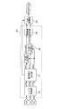
- FIG. 1 is a functional block diagram illustrating a schematic configuration of the distance measuring and imaging apparatus according to the first embodiment.
- FIG. 2 is a schematic configuration diagram showing functions of a CCD type solid-state imaging device.
- FIG. 3 is a diagram for explaining an example of timing for detecting the exposure amount of the distance measurement imaging apparatus according to the first embodiment.
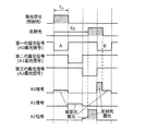
- FIG. 4 is a timing chart of the light emission signal and the exposure signal of the ranging image pickup apparatus according to the first embodiment.
- FIG. 5 is a diagram for explaining an example of timing for detecting the exposure amount of the distance measurement imaging apparatus according to the first embodiment.
- FIG. 6 is a timing chart of the light emission signal and the exposure signal of the ranging image pickup apparatus according to the first embodiment.
- FIG. 7 is a functional block diagram illustrating an example of a schematic configuration of a signal amount comparison unit of the distance image pickup device according to the modification of the first embodiment.
- FIG. 8 is a timing chart of the light emission signal and the exposure signal of the distance measurement imaging apparatus according to the second embodiment.
- FIG. 9 is a timing chart of the light emission signal and the exposure signal of the distance measuring imaging apparatus according to the second embodiment.
- FIG. 10 is a timing chart of the light emission signal and the exposure signal of the distance measurement imaging apparatus according to the second embodiment.
- FIG. 11 is a timing chart of the light emission signal and the exposure signal of the distance measuring apparatus according to the first modification of the second embodiment.
- FIG. 12 is a timing chart of the light emission signal and the exposure signal of the distance measuring imaging apparatus according to the first modification of the second embodiment.
- FIG. 13 is a timing chart of the light emission signal and the exposure signal of the distance measuring imaging apparatus according to the first modification of the second embodiment.
- FIG. 14 is a timing chart of the light emission signal and the exposure signal of the distance measuring imaging apparatus according to the second modification of the second embodiment.
- FIG. 1 is a functional block diagram illustrating an example of a schematic configuration of the distance measuring and imaging apparatus 1 according to the first embodiment.
- the ranging image pickup apparatus 1 includes a light source unit 11, a solid-state image pickup unit 12, a drive control unit 13, a signal amount comparison unit 14, and a TOF calculation unit 15 (distance calculation unit 15).
- the ranging image pickup apparatus 1 includes a light source unit 11, a solid-state image pickup unit 12, a drive control unit 13, a signal amount comparison unit 14, and a TOF calculation unit 15 (distance calculation unit 15).
- the light source unit 11 has a drive circuit, a capacitor, and a light emitting element, and emits light by supplying the charge held in the capacitor to the light emitting diode.
- the light emitting element other light emitting elements such as a laser diode and a light emitting diode (LED) may be used.
- the drive control unit 13 generates a light emission signal for instructing light irradiation to the measurement target (target object OB) and an exposure signal for instructing exposure of reflected light from the target object OB.
- the light source unit 11 irradiates the target object OB with light according to the timing of receiving the light emission signal generated by the drive control unit 13.
- the solid-state imaging unit 12 performs multiple exposures on the region including the target object OB in accordance with the timing indicated by the exposure signal generated by the drive control unit 13, and RAW data (imaging) corresponding to the sum of the multiple exposure amounts. get information.
- the solid-state imaging unit 12 includes a circuit that creates and outputs RAW data such as a camera lens, a solid-state imaging device, and an A / D converter.
- the signal amount comparison unit 14 determines at least the magnitude relationship between the signal amounts in the RAW data received from the solid-state imaging unit 12, and transmits the determination to the TOF calculation unit 15 (distance calculation unit 15).
- the TOF calculation unit 15 (distance calculation unit 15) is based on the RAW data received from the solid-state imaging unit 12 or the signal based on the RAW data output from the solid-state imaging unit 12 received from the signal amount comparison unit 14.
- the TOF signal (distance signal) that is the distance information up to is calculated according to the determination result of the signal amount comparison unit 14 and output.
- the solid-state imaging unit 12 of the distance measuring and imaging device 1 according to the present embodiment is used as a CCD (Charge Coupled Device) type solid-state imaging device.
- CCD Charge Coupled Device
- FIG. 2 is a schematic configuration diagram showing functions of a CCD type solid-state imaging device.
- the CCD solid-state imaging device includes a photodiode 101, a vertical transfer unit 102, a horizontal transfer unit 103, and a signal charge detection unit 104.
- the photodiode 101 converts the received light into electric charges.
- the vertical transfer unit 102 includes a plurality of gates, and sequentially transfers charges read from the photodiode 101 in the vertical direction.
- the horizontal transfer unit 103 sequentially transfers the charges received from the vertical transfer unit 102 as packets by a plurality of gates configured by a plurality of gates.
- the signal charge detection unit 104 sequentially detects the charges received from the horizontal transfer unit, converts them into voltage signals, and outputs them.
- the substrate voltage is controlled according to the exposure signal, the photodiode 101 is exposed during the period when the exposure signal is Low, and the charge generated by the exposure is accumulated in the vertical transfer unit 102.
- FIG. 3 and FIG. 5 are diagrams for explaining an example of the timing for detecting the exposure amount of the ranging image pickup apparatus according to the first embodiment.
- an example is shown in which the number of different signal accumulation means for accumulating signals detected by the same pixel constituting the solid-state imaging unit 12 is three.
- 3A and 5A show examples of timing relationships on one screen where the drive control unit 13 outputs a light emission signal and an exposure signal, respectively.
- 3 (b) and FIG. 5 (b) show the detection timing of the exposure amount A0 in the first light emission exposure period, respectively.
- FIG. 3 (c) and FIG. Each represents the detection timing of the exposure amount A1 in the second light emission exposure period, and (d) in FIG. 3 and (d) in FIG. 5 each represent the detection timing of the exposure amount A2 in the third light emission exposure period. .
- the photodiode 101 in the first light emission exposure period, the photodiode 101 is in a period in which the first exposure signal is Low. And charges generated by the exposure are accumulated in the vertical transfer unit 102. This operation is repeated m times in this embodiment, and when the first light emission exposure period ends, the gate of the vertical transfer unit 102 is controlled to transfer the charge to a packet having no read gate.
- the first light emission exposure period is a period in which the solid-state imaging unit 12 receives the exposure signal through the first delay time and performs exposure with respect to the timing at which the light source unit 11 receives the light emission signal and emits light. It is.
- the length of the first exposure signal period is set to To which is the same as the length of the light emission signal period, and the first delay time is set to zero. That is, the first exposure signal period is set to a period during which the light emission signal is transmitted (high level).
- the second exposure signal is in the Low period. 101 is exposed, and charges generated by the exposure are accumulated in the vertical transfer unit 102. In this embodiment, this operation is repeated m times, and when the second light emission exposure period ends, the gate of the vertical transfer unit 102 is controlled to transfer the charge to a packet having no readout gate.
- the second light emission exposure period is a period for performing exposure by receiving an exposure signal through a second delay time different from the first delay time with respect to the timing at which the solid-state imaging unit 12 receives the light emission signal. is there.
- the length of the second exposure signal period is set to To which is the same as the length of the light emission signal period and the length of the first exposure signal period, and the second delay time is the first delay time 0.
- the first exposure signal period are set to To.
- the photodiode in the third light-emission exposure period, the photodiode is used while the third exposure signal is Low. 101 is exposed, and charges generated by the exposure are accumulated in the vertical transfer unit 102. In this embodiment, this operation is repeated m times, and when the third light emission exposure period ends, the gate of the vertical transfer unit 102 is controlled, and the charge exposed by the first exposure signal is present in the readout gate. Forward as it comes in the packet.
- the third light emission exposure period refers to the exposure by receiving the exposure signal through a third delay time different from the first and second delay times with respect to the timing at which the solid-state imaging unit 12 receives the light emission signal. It is a period to perform.
- the length of the third exposure signal period is set to To which is the same as the length of the light emission signal period and the lengths of the first and second exposure signal periods, and the third delay time is the first delay time.
- the delay time 0, the first exposure signal period To, and the second exposure period To are set to 2 ⁇ To.
- this series of operations is repeated N times in this embodiment, and then the transfer of the vertical transfer unit 102 and the transfer of the horizontal transfer unit 103 are sequentially repeated, and the charge is converted into a voltage signal by the signal charge detection unit 104. And output.
- a plurality of units already configured in the vertical transfer unit 102 as means for accumulating signals obtained in a plurality of exposure periods with different timings of exposure signals for receiving reflected light from the target object OB with respect to the light emission signals. Packets can be used. Therefore, it is not necessary to form additional signal storage means. If the area is the same, the photodiode 101 can be formed larger, the saturation sensitivity can be increased, the maximum received light amount is increased, and high-precision distance measurement is possible. Can be realized.
- CMOS image sensor CMOS solid-state imaging device
- the solid-state imaging device used in the present embodiment is not limited to the CCD image sensor, and a CMOS image sensor (CMOS solid-state imaging device) or the like is considered in consideration of other requirements as a range-finding imaging device. Even when other solid-state imaging devices (image sensors) are used, the same effect (an improvement in distance measurement accuracy by S / N improvement, etc.) can be obtained.
- FIGS. 4 and 6 are timing charts of the light emission signal and the exposure signal of the distance measuring image pickup apparatus according to the first embodiment, respectively.
- 3 (b), (c) and (d), FIG. 4, FIG. 5 (b), (c) and (d), and FIG. 6 show the ranging imaging according to the first embodiment.
- 3 is a diagram illustrating details of the operation of the device 1.
- FIG. More specifically, an example of the timing relationship between the light emission signal generated by the drive control unit 13 and the exposure signal is shown. Of these, FIGS. 4 and 6 show the timings of the light emission signal and the exposure signal on the same sheet in order to make it easier to understand the relationship between the exposure periods at which the timings of the exposure signals for receiving the reflected light are different. Is.
- the number of different signal accumulation means for accumulating signals detected by the same pixel constituting the solid-state imaging unit 12 is three.
- the drive control unit 13 outputs a first exposure signal, a second exposure signal, and a third exposure signal at different timings at which the solid-state imaging unit 12 receives reflected light from the target object OB with respect to the light emission signal.
- the lengths of the first, second, and third exposure signal periods are set to the same TO as the length of the light emission signal period, and the light source unit 11 receives the light emission signal and emits light.
- the delay time of the first exposure signal is set to zero. That is, the first exposure signal period is set to a period during which the light emission signal is transmitted (high level).
- the delay time of the second exposure signal is set to To obtained by adding the first delay time 0 and the first exposure signal period To, and the delay time of the third exposure signal is the second delay time.
- the time To and the second exposure period To are set to 2 ⁇ To. Therefore, the exposure amount of the background light becomes equal in the first, second and third exposure signal periods.
- FIG. 3 and (a) in FIG. 5 show examples of timing relationships in one screen of the light emission signal and the first, second and third exposure signals.
- the repetition of the light emission signal and the exposure signal in the first, second, and third light emission exposure periods is m times, and a series of timings is set as one set, and this is repeatedly output N times, The accumulated exposure signal is output. Therefore, the sum of the exposure amount a0 based on the first exposure signal is A0, the sum of the exposure amount a1 based on the second exposure signal is A1, and the sum of the exposure amount a2 based on the third exposure signal is A2.
- the delay Td due to the optical path of the reflected light from the target object OB with respect to the light emission signal timing (irradiation light) is a value obtained by adding the first delay time 0 and the first exposure signal period To ( That is, the case where it is less than To) is shown.
- the exposure is performed so as to include all of the reflected light from the target object OB in a period obtained by adding the first exposure signal period and the second exposure signal period. Further, the exposure amount in the second exposure signal period increases as the delay Td with respect to the light emission signal timing of the reflected light from the target object OB increases.
- the third exposure signal period only background light is exposed.
- the signal amount comparison unit 14 compares the total exposure amount A0 based on the first exposure signal with the total exposure amount A2 based on the third exposure signal, and makes a determination as shown in the following equation 1.
- the signal amount comparison unit 14 transmits the determination result of Expression 1 to the TOF calculation unit 15.
- the TOF calculation unit 15 can calculate the distance L by performing the calculation of Expression 2 below.
- the delay Td due to the optical path of the reflected light from the target object OB with respect to the light emission signal timing (irradiation light) is a value obtained by adding the first delay time 0 and the first exposure signal period To ( That is, the case of To) or more is shown.
- the exposure is performed so as to include all of the reflected light from the target object OB in a period obtained by adding the second exposure signal period and the third exposure signal period.
- the exposure amount in the third exposure signal period increases as the delay Td with respect to the light emission signal timing of the reflected light from the target object OB increases. Further, only the background light is exposed in the first exposure signal period.
- the signal amount comparison unit 14 compares the sum A0 of the exposure amount based on the first exposure signal with the sum A2 of the exposure amount based on the third exposure signal, and determines as in the following Expression 3.
- the signal amount comparison unit 14 transmits the determination result of Expression 3 to the TOF calculation unit 15.
- the TOF calculation unit 15 can calculate the distance L by performing the calculation of Expression 4 below.
- the exposure period is a period in which the reflected light from the target object OB is exposed with respect to the timing of the light emission signal. Then, by changing the expression of the TOF calculation according to the result of comparing the magnitude relations of the signal amounts of different signal accumulation means, the exposure period is extended while performing background light removal.
- the distance measurement range (limit) is not limited to c ⁇ To / 2, but doubles to 2 ⁇ (c ⁇ To / 2). Thereby, without increasing the pulse width TO of the light source, the distance measurement range can be expanded to at least one of the far side, the near side, or both by setting the first delay time. Therefore, it is possible to realize a ranging imaging apparatus having a high accuracy and a wide ranging range.
- FIG. 7 is a functional block diagram illustrating an example of a schematic configuration of a signal amount comparison unit of the distance image pickup device according to the modification of the first embodiment.
- the signal amount comparison unit 24 includes a noise removal unit 26, a signal distribution unit 27, a background light removal unit 28, and an abnormal value determination unit 29.
- the noise removing unit 26 removes noise from the RAW data received from the solid-state imaging unit 12.
- the signal distribution unit 27 includes only a signal including a plurality of reflected lights and a background light based on the magnitude relation of signal amounts between signals stored in a plurality of different signal storage units in the RAW data after noise removal received from the noise removal unit 26. And the determination result of the magnitude relation of the signal amount is transmitted to the TOF calculation unit 25 (distance calculation unit 25).
- the background light removal unit 28 removes the background light signal by subtracting the signal of only the background light from the signal including the plurality of reflected lights received from the signal distribution unit 27.
- the abnormal value determination unit 29 determines an abnormal value from the signal obtained by removing the plurality of background lights received from the background light removal unit 28 and transmits the result to the TOF calculation unit 25.
- the noise removal unit 26 includes a total exposure amount A0 based on the first exposure signal, a total exposure amount A1 based on the second exposure signal, and a total exposure amount based on the third exposure signal in the RAW data received from the solid-state imaging unit 12.
- Each noise of A2 is removed, and each exposure amount from which the noise is removed is transmitted to the signal distribution unit 27 as A0nr, A1nr, and A2nr.
- the signal distribution unit 27 is a value obtained by adding the first delay time 0 and the first exposure signal period to the delay Td due to the optical path of the reflected light from the target object OB with respect to the light emission signal timing (irradiation light) (that is, TO If it is less than), it is determined as in the following formula 5.
- the signal distribution unit 27 sets the exposure amount to decrease as S0nr, the increase as S1nr, and the exposure amount of only the background light as BGnr as the delay Td with respect to the light emission signal timing of the reflected light from the target object OB increases.
- the signal is distributed as shown in the following Expression 6 and transmitted to the background light removal unit 28.
- the determination result J 0 is transmitted to the TOF calculation unit 25.
- the delay Td due to the optical path of the reflected light from the target object OB with respect to the light emission signal timing (irradiation light) is not less than the value obtained by adding the first delay time 0 and the first exposure signal period (ie, To).
- the signal distribution unit 27 performs determination as in the following Expression 7, distributes the signal as in the following Expression 8, and transmits the signal to the background light removal unit 28.
- the background light removing unit 28 removes the background light, performs the following Expression 9 and transmits it to the abnormal value determining unit 29.
- the abnormal value determination unit 29 determines the signal amounts of S0subBG and S1subBG received from the background light removal unit 28. When the target object OB is out of the measurement range, the total exposure amount A0 based on the first exposure signal, the total exposure amount A1 based on the second exposure signal, and the total exposure amount A2 based on the third exposure signal are almost the same. It becomes signal amount. At this time, if the signal amounts of S0subBG and S1subBG are very close to zero, the abnormal value determination unit 29 determines that the abnormal value is outside the measurement range and transmits the abnormal value to the TOF calculation unit 25. And S1subBG are transmitted to the TOF calculation unit 25.
- the TOF calculation unit 25 can calculate the distance L by performing the calculation of Expression 10 below.
- the distance measurement range (limit) is not limited to c ⁇ To / 2, and not only doubles to 2 ⁇ (c ⁇ To / 2), but also compares the amount of signal between signals from which noise has been removed. Therefore, erroneous determination can be prevented. Therefore, it is possible to realize a ranging imaging device with higher accuracy and a wider ranging range.
- the signal amount of multiple signals from which background light has been removed is determined, it is observed that the signal amount of all of the multiple signals from which background light has been removed is very close to zero when the measurement object is outside the measurement range. The As a result, it is possible to easily determine the outside of the distance measurement range, and it is possible to realize a distance measurement imaging device with a higher accuracy and a wider distance measurement range.
- FIG. 9 and FIG. 10 are timing charts of the light emission signal and the exposure signal of the distance measuring and imaging apparatus 1 according to the second embodiment, respectively.
- an example of the timing relationship between the light emission signal and the exposure signal generated by the drive control unit 13 is shown, and it is easy to understand the relationship between a plurality of exposure periods with different timings of the exposure signal that receives reflected light.
- each timing of the light emission signal and the exposure signal is shown on the same sheet.
- an example is shown in which the number of different signal accumulating units that accumulate signals detected by the same pixel constituting the solid-state imaging unit 12 is three.
- the drive control unit 13 outputs a first exposure signal, a second exposure signal, and a third exposure signal at different timings at which the solid-state imaging unit 12 receives reflected light from the target object OB with respect to the light emission signal.
- the length of the exposure signal period of the first exposure signal is set to the same To as the length of the light emission signal period.
- the first exposure signal includes the first exposure signal A having an exposure period in which the delay time is set to 0 with respect to the timing at which the light source unit 11 receives the light emission signal and emits light, and the third exposure time. It is composed of two exposure signals, a first exposure signal B having an exposure period set to 3 * To, which is obtained by adding a signal delay time 2 * To and a third exposure period To.
- the lengths of the second and third exposure signal periods are set to the same To as the length of the light emission signal period.
- the delay time of the second exposure signal is set to To obtained by adding the delay time 0 of the first exposure signal A and the exposure period (To) of the first exposure signal A.
- the delay time of the third exposure signal is set to 2 ⁇ To obtained by adding the delay time To of the second exposure signal and the second exposure signal period To.
- the exposure amount of the background light is equal in the second and third exposure signal periods, and doubles in the first exposure signal period.
- the delay Td due to the optical path of the reflected light from the target object OB with respect to the light emission signal timing is the delay time 0 of the first exposure signal A and the first exposure signal A.
- the case where the exposure period To is less than the added value To is shown.
- the exposure is performed so as to include all of the reflected light from the target object OB in the period obtained by adding the exposure period of the first exposure signal A and the second exposure signal period.
- the exposure amount in the second exposure signal period increases as the delay Td of the reflected light from the target object OB with respect to the light emission signal timing increases.
- the third exposure signal period only background light is exposed.
- the signal amount comparison unit 14 compares the total exposure amount A0 based on the first exposure signal with the total exposure amount A1 based on the second exposure signal and the total exposure amount A2 based on the third exposure signal, Judgment is made as shown in Equation 11 below.
- the signal amount comparison unit 14 transmits the determination result of Expression 11 to the TOF calculation unit 15.
- the distance L can be calculated by performing the calculation of Expression 12 below.
- the delay Td due to the optical path of the reflected light from the target object OB with respect to the emission signal timing (irradiation light) is added by the delay time 0 of the first exposure signal A and the exposure period To of the first exposure signal A.
- a case is shown in which the delay time To of the second exposure signal and the second exposure signal period To are less than the value 2 ⁇ To, which is equal to or greater than the set value To.
- the exposure is performed so as to include all of the reflected light from the target object OB in a period obtained by adding the second exposure signal period and the third exposure signal period. Further, the exposure amount in the third exposure signal period increases as the delay Td with respect to the light emission signal timing of the reflected light from the target object OB increases. Further, only the background light is exposed in the first exposure signal period.
- the signal amount comparison unit 14 compares the total exposure amount A0 based on the first exposure signal with the total exposure amount A1 based on the second exposure signal and the total exposure amount A2 based on the third exposure signal, Judgment is made as shown in Equation 13 below.
- the signal amount comparison unit 14 transmits the determination result of Expression 13 to the TOF calculation unit 15.
- the TOF calculation unit 15 can calculate the distance L by performing the calculation of Expression 14 below.
- the delay Td due to the optical path of the reflected light from the target object OB with respect to the emission signal timing is a value 2 obtained by adding the delay time To of the second exposure signal and the second exposure signal period To.
- the exposure is performed so as to include all of the reflected light from the target object OB in a period in which the third exposure signal period and the first exposure signal period A are added.
- the exposure amount during the exposure period of the first exposure signal B increases as the delay Td of the reflected light from the target object OB with respect to the light emission signal timing increases.
- the second exposure signal period only background light is exposed.
- the signal amount comparison unit 14 compares the total exposure amount A0 based on the first exposure signal with the total exposure amount A1 based on the second exposure signal and the total exposure amount A2 based on the third exposure signal, Determination is made as shown in Equation 15 below.
- the signal amount comparison unit 14 transmits the determination result of Expression 15 to the TOF calculation unit 15.
- the TOF calculation unit 15 can calculate the distance L by performing the calculation of Expression 16 below.
- the exposure period is a period in which the reflected light from the target object OB is exposed with respect to the timing of the light emission signal.
- at least one identical signal storage means of the signal storage means stores signals exposed at a plurality of different timings with respect to the light emission signal. Then, by changing the expression of the TOF calculation according to the comparison result of the signal amounts of a plurality of different signal storage means, the exposure period is further extended while performing background light removal without increasing the signal storage means.
- the distance measuring range is not limited to c ⁇ To / 2, but is three times as large as 3 ⁇ (c ⁇ To / 2).
- the distance measurement range can be further expanded to at least one of the far side, the near side, or both by setting the first delay time. Therefore, it is possible to realize a ranging imaging apparatus having a high accuracy and a wide ranging range.
- Modification 1 of Embodiment 2 11, 12, and 13 are timing charts of the light emission signal and the exposure signal of the ranging image pickup apparatus 1 according to the first modification of the second embodiment, respectively.
- an example of the timing relationship between the light emission signal and the exposure signal generated by the drive control unit 13 is shown, and it is easy to understand the relationship between a plurality of exposure periods with different timings of the exposure signal that receives reflected light.
- each timing of the light emission signal and the exposure signal is shown on the same sheet.
- an example is shown in which the number of different signal accumulating units that accumulate signals detected by the same pixel constituting the solid-state imaging unit 12 is three.
- the drive control unit 13 outputs a first exposure signal, a second exposure signal, and a third exposure signal at different timings at which the solid-state imaging unit 12 receives reflected light from the target object OB with respect to the light emission signal.
- the length of the exposure signal period of the first exposure signal is set to the same To as the length of the light emission signal period.
- the first exposure signal includes the first exposure signal A having an exposure period in which the delay time is set to 0 with respect to the timing at which the light source unit 11 receives the light emission signal and emits light, and the third exposure time. It is composed of two exposure signals, a first exposure signal B having an exposure period set to 3 ⁇ To, which is obtained by adding a delay time 2 ⁇ To of the signal A and an exposure period To of the third exposure signal A. Has been.
- the length of the exposure signal period of the second exposure signal is set to the same To as the length of the light emission signal period.
- the second exposure signal is composed of two exposure signals of a second exposure signal A and a second exposure signal B.
- the second exposure signal A has an exposure period set to To that is obtained by adding the delay time 0 of the first exposure signal A and the exposure period To of the first exposure signal A.
- the second exposure signal B has an exposure period whose delay time is set to be longer than 4 * To obtained by adding the delay time 3 * To of the first exposure signal B and the exposure period To of the first exposure signal B.
- the length of the exposure signal period of the third exposure signal is set to To which is the same as the length of the light emission signal period.
- the third exposure signal is composed of two exposure signals of a third exposure signal A and a third exposure signal B.
- the third exposure signal A has an exposure period set to 2 ⁇ To, which is the sum of the delay time To of the second exposure signal A and the exposure period To of the second exposure signal A.
- the third exposure signal B has an exposure period whose delay time is set to be longer than 4 * To obtained by adding the delay time 3 * To of the first exposure signal B and the exposure period To of the first exposure signal B.
- the exposure amount of the background light becomes equal in the first, second and third exposure signal periods.
- the delay Td due to the optical path of the reflected light from the target object OB with respect to the emission signal timing (irradiation light) is the delay time 0 of the first exposure signal A and the first exposure signal A.
- the case where the exposure period To is less than the added value To is shown.
- the exposure is performed so as to include all the reflected light from the target object OB in a period obtained by adding the exposure period of the first exposure signal A and the exposure period of the second exposure signal A. Further, the exposure amount of the second exposure signal A during the exposure period increases as the delay Td of the reflected light from the target object OB and the like with respect to the light emission signal timing increases.
- the third exposure signal period only background light is exposed.
- the signal amount comparison unit 14 compares the total exposure amount A0 based on the first exposure signal with the total exposure amount A1 based on the second exposure signal and the total exposure amount A2 based on the third exposure signal, Judgment is made as shown in Equation 17 below.
- the signal amount comparison unit 14 transmits the determination result of Expression 17 to the TOF calculation unit 15.
- the distance L can be calculated by performing the calculation of Expression 18 below.
- the delay Td due to the optical path of the reflected light from the target object OB with respect to the emission signal timing (irradiation light) is added by the delay time 0 of the first exposure signal A and the exposure period To of the first exposure signal A.
- a case is shown in which the delay time To of the second exposure signal A and the exposure period To of the second exposure signal A are less than the value 2 ⁇ To, which is equal to or greater than the value To.
- the exposure is performed so as to include all of the reflected light from the target object OB in a period obtained by adding the exposure period of the second exposure signal A and the exposure period of the third exposure signal A.
- the exposure amount of the third exposure signal A during the exposure period increases as the delay Td of the reflected light from the target object OB increases with respect to the light emission signal timing. Further, only the background light is exposed in the first exposure signal period.
- the signal amount comparison unit 14 compares the total exposure amount A0 based on the first exposure signal with the total exposure amount A1 based on the second exposure signal and the total exposure amount A2 based on the third exposure signal, Determination is made as shown in Equation 19 below.
- the signal amount comparison unit 14 transmits the determination result of Expression 19 to the TOF calculation unit 15.
- the TOF calculation unit 15 can calculate the distance L by performing the calculation of Expression 20 below.
- the delay Td due to the optical path of the reflected light from the target object OB with respect to the emission signal timing is a value 2 obtained by adding the delay time To of the second exposure signal and the second exposure signal period To.
- the exposure is performed so as to include all of the reflected light from the target object OB in a period in which the exposure period of the third exposure signal A and the exposure period of the first exposure signal B are added. Further, the exposure amount during the exposure period of the first exposure signal B increases as the delay Td of the reflected light from the target object OB with respect to the light emission signal timing increases. In the second exposure signal period, only background light is exposed.
- the signal amount comparison unit 14 compares the total exposure amount A0 based on the first exposure signal with the total exposure amount A1 based on the second exposure signal and the total exposure amount A2 based on the third exposure signal, Judgment is made as shown in Equation 21 below.
- the signal amount comparison unit 14 transmits the determination result of Expression 21 to the TOF calculation unit 15.
- the TOF calculation unit 15 can calculate the distance L by performing the calculation of Expression 22 below.
- the exposure period is a period in which the reflected light from the target object OB is exposed with respect to the timing of the light emission signal.
- the same signal storage means stores the signals exposed at a plurality of different timings with respect to the light emission signal, so that the exposure amount of the background light becomes equal, and the plurality of different signal storage means It is easier and more accurate to compare the magnitude relations of the signal amounts. Thereby, by changing the expression of the TOF calculation according to the comparison result, the exposure period is further extended while executing the background light removal without increasing the signal accumulation means.
- the distance measuring range is not limited to c ⁇ To / 2, but is three times as large as 3 ⁇ (c ⁇ To / 2).
- the distance measurement range can be further expanded to at least one of the far side, the near side, or both by setting the first delay time. Therefore, it is possible to realize a ranging imaging apparatus having a high accuracy and a wide ranging range.
- FIG. 14 is a timing chart of the light emission signal and the exposure signal of the distance measurement imaging apparatus 1 according to the second modification of the second embodiment. Specifically, an example of the timing relationship between the light emission signal and the exposure signal generated by the drive control unit 13 is shown, and it is easy to understand the relationship between a plurality of exposure periods with different timings of the exposure signal that receives reflected light. In addition, each timing of the light emission signal and the exposure signal is shown on the same sheet. In the present embodiment, an example is shown in which the number of different signal accumulating units that accumulate signals detected by the same pixel constituting the solid-state imaging unit 12 is four.
- the drive control unit 13 has a first exposure signal, a second exposure signal, a third exposure signal, and a fourth exposure signal at different timings at which the solid-state imaging unit 12 receives reflected light from the target object OB with respect to the light emission signal.
- An exposure signal is output.
- the length of each exposure signal period of the first exposure signal is set to To which is the same as the length of the light emission signal period.
- the first exposure signal includes a first exposure signal A having an exposure period in which a delay time is set to 0 with respect to a timing at which the light source unit 11 receives the light emission signal and emits light, and a fourth exposure time with a delay time. It consists of two exposure signals: a delay time 3 ⁇ To of the signal A and an exposure period To of the fourth exposure signal A, or a first exposure signal B having an exposure period set to 4 ⁇ To. ing.
- the length of each exposure signal period of the second exposure signal is set to To which is the same as the length of the light emission signal period.
- the second exposure signal is composed of two exposure signals of a second exposure signal A and a second exposure signal B.
- the second exposure signal A has an exposure period set to To that is obtained by adding the delay time 0 of the first exposure signal A and the exposure period To of the first exposure signal A.
- the second exposure signal B has an exposure period whose delay time is set larger than 6 * To, which is obtained by adding the delay time 5 * To of the third exposure signal B and the exposure period To of the third exposure signal B.
- the length of each exposure signal period of the third exposure signal is set to To which is the same as the length of the light emission signal period.
- the third exposure signal is composed of two exposure signals of a third exposure signal A and a third exposure signal B.
- the third exposure signal A has an exposure period set to 2 ⁇ To, which is the sum of the delay time To of the second exposure signal A and the exposure period To of the second exposure signal A.
- the third exposure signal B has an exposure period set to 5 ⁇ To, which is the sum of the delay time 4 ⁇ To of the first exposure signal B and the exposure period To of the first exposure signal B. .
- the length of each exposure signal period of the fourth exposure signal is set to To which is the same as the length of the light emission signal period.
- the fourth exposure signal is composed of two exposure signals of a fourth exposure signal A and a fourth exposure signal B.
- the fourth exposure signal A has an exposure period set to 3 ⁇ To, which is the sum of the delay time 2 ⁇ To of the third exposure signal A and the exposure period To of the third exposure signal A.
- the fourth exposure signal B has an exposure period in which the delay time is set to be longer than 6 * To obtained by adding the delay time 5 * To of the third exposure signal B and the exposure period To of the third exposure signal B.
- the exposure amount of the background light becomes equal in the first, second, third and fourth exposure signal periods.
- the signal amount comparison unit 14 calculates the total exposure amount A0 based on the first exposure signal, the total exposure amount A1 based on the second exposure signal, the total exposure amount A2 based on the third exposure signal, and the fourth exposure.
- the total exposure amount A3 based on the signal is compared, and a determination is made as shown in Expression 23 below.
- the signal amount comparison unit 14 transmits the determination result of Expression 23 to the TOF calculation unit 15.
- the distance L can be calculated by performing the calculation of Expression 24 below.
- the background light exposure amount BG may be any of A2, A3, and (A2 + A3) / 2.
- the exposure period of the second exposure signal A The exposure is performed so as to include all of the reflected light from the target object OB in a period obtained by adding the exposure periods of the three exposure signals A. Further, the exposure amount of the third exposure signal A during the exposure period increases as the delay Td of the reflected light from the target object OB increases with respect to the light emission signal timing. Further, only the background light is exposed in the first exposure signal period and the fourth exposure signal period.
- the signal amount comparison unit 14 calculates the total exposure amount A0 based on the first exposure signal, the total exposure amount A1 based on the second exposure signal, the total exposure amount A2 based on the third exposure signal, and the fourth exposure.
- the total exposure amount A3 based on the signal is compared, and a determination is made as in the following Expression 25.
- the signal amount comparison unit 14 transmits the determination result of Expression 25 to the TOF calculation unit 15.
- the TOF calculation unit 15 can calculate the distance L by performing the calculation of Expression 26 below.
- the background light exposure amount BG may be any of A0, A3, and (A0 + A3) / 2.
- the delay time Td due to the optical path of the reflected light from the target object OB with respect to the light emission signal timing is a value 2 obtained by adding the delay time To of the second exposure signal A and the exposure period To of the second exposure signal A If the delay time 2 ⁇ To of the third exposure signal A and the exposure period To of the third exposure signal A are less than 3 ⁇ To, which is greater than or equal to ⁇ To, the third exposure signal A
- the exposure is performed so as to include all of the reflected light from the target object OB in a period obtained by adding the exposure period of 4 and the exposure period of the fourth exposure signal A.
- the exposure amount in the fourth exposure signal A increases as the delay Td of the reflected light from the target object OB with respect to the light emission signal timing increases. Further, only the background light is exposed in the first exposure signal period and the second exposure signal period.
- the signal amount comparison unit 14 calculates the total exposure amount A0 based on the first exposure signal, the total exposure amount A1 based on the second exposure signal, the total exposure amount A2 based on the third exposure signal, and the fourth exposure.
- the total exposure amount A3 based on the signal is compared, and a determination is made as shown in Expression 27 below.
- the signal amount comparison unit 14 transmits the determination result of Expression 27 to the TOF calculation unit 15.
- the TOF calculation unit 15 can calculate the distance L by performing the calculation of Expression 28 below.
- the background light exposure amount BG may be any of A0, A1, and (A0 + A1) / 2.
- the delay Td due to the optical path of the reflected light from the target object OB with respect to the light emission signal timing is added to the delay time 2 ⁇ To of the third exposure signal A and the exposure period To of the third exposure signal A. If the value is 3 ⁇ To or more and is less than the value 4 ⁇ To obtained by adding the delay time 3 ⁇ To of the fourth exposure signal A and the exposure period To of the fourth exposure signal A, the fourth exposure is performed.
- the exposure is performed so as to include all the reflected light from the target object OB in a period in which the exposure period of the signal A and the exposure period of the first exposure signal B are added. Further, the exposure amount during the exposure period of the first exposure signal B increases as the delay Td of the reflected light from the target object OB with respect to the light emission signal timing increases. Further, only the background light is exposed in the second exposure signal period and the third exposure signal period.
- the signal amount comparison unit 14 calculates the total exposure amount A0 based on the first exposure signal, the total exposure amount A1 based on the second exposure signal, the total exposure amount A2 based on the third exposure signal, and the fourth exposure.
- the total exposure amount A3 based on the signal is compared, and a determination is made as shown in Expression 29 below.
- the signal amount comparison unit 14 transmits the determination result of Expression 29 to the TOF calculation unit 15.
- the TOF calculation unit 15 can calculate the distance L by performing the calculation of Expression 30 below.
- the background light exposure amount BG may be any of A1, A2, and (A1 + A2) / 2.
- the delay Td due to the optical path of the reflected light from the target object OB with respect to the light emission signal timing is obtained by adding the delay time 3 ⁇ To of the fourth exposure signal A and the exposure period To of the fourth exposure signal A.
- the reflected light from the target object OB is included in the period obtained by adding the exposure period of the first exposure signal B and the exposure period of the third exposure signal B. Exposed.
- the exposure amount of the third exposure signal B during the exposure period increases as the delay Td of the reflected light from the target object OB increases with respect to the light emission signal timing. Further, only the background light is exposed in the second exposure signal period and the fourth exposure signal period.
- the timing chart of FIG. 14 shows this case.
- the signal amount comparison unit 14 calculates the total exposure amount A0 based on the first exposure signal, the total exposure amount A1 based on the second exposure signal, the total exposure amount A2 based on the third exposure signal, and the fourth exposure.
- the total exposure amount A3 based on the signal is compared, and a determination is made as shown in Expression 31 below.
- the signal amount comparison unit 14 transmits the determination result of Expression 31 to the TOF calculation unit 15.
- the TOF calculation unit 15 can calculate the distance L by performing the calculation of Expression 32 below.
- the background light exposure amount BG may be any of A1, A3, and (A1 + A3) / 2.
- the exposure period is a period in which the reflected light from the target object OB is exposed with respect to the timing of the light emission signal.
- the same signal storage means stores the signals exposed at a plurality of different timings with respect to the light emission signal, so that the exposure amount of the background light becomes equal, and the plurality of different signal storage means It is easier and more accurate to compare the magnitude relations of the signal amounts. Thereby, by changing the expression of the TOF calculation according to the comparison result, the exposure period is further extended while executing the background light removal without increasing the signal accumulation means.
- the distance measurement range is not limited to 2 ⁇ (c ⁇ To / 2) when one of the signal storage means is used exclusively for exposure of background light, and 5 ⁇ (c ⁇ To / 2). And spread 2.5 times.
- the distance measurement range can be further expanded to at least one of the far side, the near side, or both by setting the first delay time. Therefore, it is possible to realize a ranging imaging apparatus having a high accuracy and a wide ranging range.
- the ranging imaging device has been described.
- the configuration of the ranging imaging device according to the present disclosure is not limited to the ranging imaging device that measures the distance based on the distance information, and other physical quantities (eg, shape)
- the present invention can also be applied to a physical quantity detection device that accurately detects temperature, radiation concentration, and the like, and an imaging device that accurately describes captured data.
- the distance measuring and imaging apparatus 1 As described above with reference to the drawings, the distance measuring and imaging apparatus 1 according to the embodiment of the present invention generates a light emission signal instructing light irradiation and an exposure signal instructing exposure of reflected light. Then, the light source unit 11 that irradiates light according to the timing indicated by the light emission signal, and the imaging information corresponding to the exposure amount of the exposure performed by exposing the region including the target object OB according to the timing indicated by the exposure signal.
- the solid-state imaging unit 12 that generates RAW data, the signal amount comparison unit 14 that determines the magnitude relationship of the signal amount in the RAW data, and the target object OB based on the determination result of the magnitude relationship of the signal amount by the signal amount comparison unit 14 And a TOF calculation unit 15 that generates and outputs a distance signal indicating the distance.
- the solid-state imaging unit 12 includes a plurality of different signal storage areas for storing signals detected by the same pixel, and each of the different signal storage areas is transmitted from the target object OB with respect to the timing of the light emission signal.
- the signal amount comparison unit 14 determines the magnitude relationship between the signal amounts of a plurality of signals accumulated in different signal accumulation regions. Then, the TOF calculation unit 15 receives the RAW data from the solid-state imaging unit 12 or the signal amount comparison unit 14, and calculates the distance to the target object OB using the calculation formula selected according to the determination result of the signal amount magnitude relationship. Thus, a distance signal is generated and output.
- the plurality of different signal storage areas allow background light removal without being used exclusively for background light, and exposure signals that expose the reflected light from the target object OB with respect to the timing of the emission signal. Are used to store signals exposed during different exposure periods. This extends the exposure period and extends the period during which the reflected light can be captured, so that the range can be expanded to at least one or both of the far side and near side without increasing the pulse width of the light source. Can do.
- the solid-state imaging unit 12 performs multiple exposures on the region including the target object OB according to the timing indicated by the exposure signal, and RAW data that is imaging information corresponding to the sum of the exposure amounts of the multiple exposures. May be generated.
- At least one same signal storage area may store a plurality of signals exposed at a plurality of different timings of the exposure signal with respect to the light emission signal.
- the signal amount comparison unit 14 includes a noise removal unit 26 that removes noise from the RAW data received from the solid-state imaging unit 12, and a plurality of different signal accumulation regions in the RAW data after noise removal received from the noise removal unit 26.
- a signal distribution that distributes a signal including a plurality of reflected lights and a signal of only background light based on the magnitude relation of the accumulated signal quantities of the plurality of signals and transmits a determination result of the magnitude relation of the signal quantities to the TOF calculation unit 25 27, a background light removing unit 28 for removing a background light signal by subtracting a signal of only background light from a signal including a plurality of reflected lights received from the signal distribution unit 27, and a background light removing unit 28 for background light.
- the present invention can be realized not only as a distance measuring and imaging apparatus having such a characteristic configuration but also as a distance measuring method of the distance measuring and imaging apparatus.
- the distance measuring method of the distance measuring and imaging apparatus corresponds to the timing of the light emission signal corresponding to each of a plurality of different signal storage areas in which the solid-state imaging unit 12 stores signals detected by the same pixel.
- a plurality of signals exposed in exposure periods having different exposure signal timings are accumulated, and the signal amount comparison unit 14 determines the magnitude relationship of the signal amounts of the signals accumulated in the plurality of different signal accumulation regions, and the TOF calculation unit 15 selects an arithmetic expression for calculating the distance to the target object OB according to the determination result of the signal amount comparison unit 14, and calculates the distance to the target object OB using the selection expression, thereby obtaining the distance signal.
- a plurality of different signal accumulation regions enable background light removal without being used exclusively for background light, and the timing of the exposure signal that exposes the reflected light from the target object OB with respect to the timing of the emission signal. It is used to store signals exposed during different exposure periods. This extends the exposure period and extends the period during which the reflected light can be captured, so that the range can be expanded to at least one or both of the far side and near side without increasing the pulse width of the light source. Can do.
- the present invention can be realized not only as a ranging imaging device and a ranging method having such a characteristic configuration, but also as a solid-state imaging device using the solid-state imaging unit 12 used in the ranging imaging device. can do. That is, the solid-state imaging used in the distance-measuring imaging device 1 including the drive control unit 13, the light source unit 11, the solid-state imaging device that is the solid-state imaging unit 12, the signal amount comparison unit 14, and the TOF calculation unit 15.
- Each of the plurality of different signal accumulation regions is an apparatus for accumulating signals exposed in exposure periods having different exposure signal timings for instructing exposure of reflected light from the target object OB with respect to the timing of the light emission signal. It is characterized by.
- the plurality of different signal storage areas allow background light removal without being used exclusively for background light, and exposure signals that expose the reflected light from the target object OB with respect to the timing of the emission signal. Are used to store signals exposed during different exposure periods. This extends the exposure period and extends the period during which the reflected light can be captured, so that the range can be expanded to at least one or both of the far side and near side without increasing the pulse width of the light source. Can do.
- the solid-state imaging device may be a CCD type solid-state imaging device.
- a plurality of packets already configured in the vertical transfer unit can be used as an area for accumulating signals obtained in a plurality of different exposure periods. Therefore, it is not necessary to form additional signal accumulating means, and if the area is the same, the photodiode can be formed larger, the saturation sensitivity can be increased, the maximum received light amount is increased, and high-precision ranging is achieved. realizable.
- an operation of collectively resetting a plurality of photodiodes, so-called global reset can be performed, and further accurate ranging can be realized.
- the ranging imaging device of this indication has been explained based on the above-mentioned embodiment, the ranging imaging device of this indication is not limited to the above-mentioned embodiment.
- a TOF (time of flight) method that performs distance measurement using a flight time in which light reciprocates to a measurement target is used.
- the present invention also includes a case of using other methods for distance measurement.
- the distance measuring and imaging apparatus can realize highly accurate three-dimensional measurement of an object to be measured without depending on the surrounding environment, and is useful for, for example, three-dimensional measurement of a person, a building, and the like.
Landscapes
- Engineering & Computer Science (AREA)
- Physics & Mathematics (AREA)
- General Physics & Mathematics (AREA)
- Remote Sensing (AREA)
- Radar, Positioning & Navigation (AREA)
- Computer Networks & Wireless Communication (AREA)
- Electromagnetism (AREA)
- Signal Processing (AREA)
- Multimedia (AREA)
- Optical Radar Systems And Details Thereof (AREA)
- Studio Devices (AREA)
- Measurement Of Optical Distance (AREA)
- Transforming Light Signals Into Electric Signals (AREA)
Abstract
測距撮像装置(1)は、発光信号のタイミングに従って光照射を行う光源部(11)と、対象物体OBに対して、露光信号のタイミングに従って露光を行い、当該露光の露光量に対応したRAWデータを生成する固体撮像部(12)と、RAWデータにおける信号量の大小関係を判定する信号量比較部(14)と、信号量の大小関係の判定結果に基づいて距離信号を生成して出力する距離演算部(15)とを備え、固体撮像部(12)は、同一画素で検出する信号を蓄積する異なる複数の信号蓄積領域のそれぞれに、露光信号のタイミングが異なる露光期間に露光した信号を蓄積させ、信号量比較部(14)は、異なる複数の信号蓄積領域に蓄積された複数の信号の信号量の大小関係を判定し、距離演算部(15)は、上記判定結果に従って選択した演算式を用いて対象物体OBとの距離を算出する。
Description
本発明は、測距撮像装置、その測距方法及び固体撮像装置に関する。
物体を検知する複数の方式の中で、測定対象物まで光が往復する飛行時間を利用して測距を行うTOF(time of flight)方式が知られている。
特許文献1には、2つの異なる信号蓄積手段に、光源からの光の断続動作と同期させて互いに異なる位相で電荷転送して信号蓄積を行い、蓄積信号の配分比から対象物までの距離を求め、さらに、第3の信号蓄積手段に背景光のみを信号蓄積することで、背景光除去を行って、背景光の影響を排除する従来技術を開示している。
しかしながら、特許文献1に開示された従来技術では、第3の信号蓄積手段を背景光専用にしているため、測距範囲(限界)Dは、光源のパスル幅(To)に依存し、光速(299,792,458m/s)をcとすると以下のように表される。
D=c×To/2
一方、光源のパルス幅(To)が大きくなると、測距範囲Dは大きくなるが、距離分解能が落ちるので測距精度は光源のパルス幅(To)に反比例する。つまり、測距範囲(限界)Dを広げるために光源のパルス幅(To)を大きくすると、逆に測距精度は悪くなる。
従って、開示された従来技術では、測距範囲と測距精度との両立は困難であるとの課題を有している。
上記課題に鑑み、本発明は、高い測距精度、かつ、広い測距範囲を実現する測距撮像装置、その測距方法及び固体撮像装置を提供することを目的とする。
上記課題を解決するために、本発明の一態様に係る測距撮像装置は、光照射を指示する発光信号と反射光の露光を指示する露光信号とを発生する駆動制御部と、前記発光信号が示すタイミングに従って光の照射を行う光源部と、対象物体を含む領域に対して、前記露光信号が示すタイミングに従って露光を行い、当該露光の露光量に対応した撮像情報であるRAWデータを生成する固体撮像部と、前記RAWデータにおける信号量の大小関係を判定する信号量比較部と、前記信号量比較部による前記信号量の大小関係の判定結果に基づいて前記対象物体との距離を示す距離信号を生成して出力する距離演算部とを備え、前記固体撮像部は、同一画素で検出する信号を蓄積する異なる複数の信号蓄積領域を含み、前記異なる複数の信号蓄積領域のそれぞれは、前記発光信号のタイミングに対して前記対象物体からの反射光の露光を指示する前記露光信号のタイミングが異なる露光期間に露光した前記信号を蓄積し、前記信号量比較部は、前記異なる複数の信号蓄積領域に蓄積された複数の前記信号の信号量の大小関係を判定し、前記距離演算部は、前記固体撮像部または前記信号量比較部から前記RAWデータを受け、前記信号量の大小関係の判定結果に従って選択した演算式を用いて前記対象物体との距離を算出することにより、前記距離信号を生成して出力することを特徴とする。
本発明に係る測距撮像装置によれば、光源のパルス幅を大きくすることなく高い測距精度を確保でき、かつ、測距範囲をより遠い側あるいは近い側の少なくともどちらか一方に拡げることが可能となる。
以下、本開示の実施の形態に係る測距撮像装置について、図面を参照しながら説明する。なお、以下の実施の形態は、いずれも本発明の一具体例を示すものであり、数値、形状、材料、構成要素、構成要素の配置位置及び接続形態などは、一例であり、本発明を限定するものではない。
(実施の形態1)
図1は、実施の形態1に係る測距撮像装置1の概略構成の一例を示す機能ブロック図である。同図に示すように、測距撮像装置1は、光源部11と、固体撮像部12と、駆動制御部13と、信号量比較部14と、TOF演算部15(距離演算部15)とを備える。
図1は、実施の形態1に係る測距撮像装置1の概略構成の一例を示す機能ブロック図である。同図に示すように、測距撮像装置1は、光源部11と、固体撮像部12と、駆動制御部13と、信号量比較部14と、TOF演算部15(距離演算部15)とを備える。
光源部11は、駆動回路、コンデンサ及び発光素子を有し、コンデンサに保持した電荷を発光ダイオードへ供給することで光を発する。発光素子としてはレーザダイオードや発光ダイオード(LED)等のその他の発光素子を用いてもよい。
駆動制御部13は、測定対象物(対象物体OB)への光照射を指示する発光信号と、当該対象物体OBからの反射光の露光を指示する露光信号とを発生する。
光源部11は、駆動制御部13で発生する発光信号を受信するタイミングに従って対象物体OBに対して光照射を行う。
固体撮像部12は、対象物体OBを含む領域に対して、駆動制御部13で発生する露光信号が示すタイミングに従って複数回の露光を行い、複数回の露光量の総和に対応したRAWデータ(撮像情報)を得る。固体撮像部12は、カメラレンズ、固体撮像素子、及びA/Dコンバータ等のRAWデータを作成し出力する回路を有する。
信号量比較部14は、少なくとも固体撮像部12から受けたRAWデータにおける信号量の大小関係を判定してTOF演算部15(距離演算部15)に伝える。
TOF演算部15(距離演算部15)は、固体撮像部12から受けたRAWデータまたは信号量比較部14から受けた固体撮像部12から出力されるRAWデータに基づく信号に基づいて、対象物体OBまでの距離情報であるTOF信号(距離信号)を、信号量比較部14の判定結果に応じて演算して出力する。
次に、本実施の形態に係る測距撮像装置1の固体撮像部12を、CCD(Charge Coupled Device)型の固体撮像素子として用いた場合について説明する。
図2は、CCD型の固体撮像素子の機能を表す概略構成図である。同図に示すように、CCD型固体撮像素子は、フォトダイオード101と、垂直転送部102と、水平転送部103と、信号電荷検出部104とを備える。
フォトダイオード101は、受光した光を電荷に変換する。
垂直転送部102は、複数のゲートから構成され、フォトダイオード101から読み出した電荷を順次垂直方向に転送する。
水平転送部103は、複数のゲートから構成されている複数のゲートがパケットとして垂直転送部102から受けた電荷を順次水平方向に転送する。
信号電荷検出部104は、水平転送部から受けた電荷を順次検出して電圧信号に変換して出力する。
ここで、読み出しゲートは開いた状態で、露光信号に従って基板電圧を制御し、露光信号がLowの期間でフォトダイオード101を露光し、当該露光により発生した電荷を垂直転送部102に蓄積する。
図3及び図5は、それぞれ、実施の形態1に係る測距撮像装置の露光量を検出するタイミングの一例を説明する図である。本実施の形態の場合、固体撮像部12を構成する同一画素で検出する信号を蓄積する異なる複数の信号蓄積手段の数が3である例を示す。
なお、図3の(a)及び図5の(a)は、それぞれ、駆動制御部13が発光信号と露光信号とを出力する1画面におけるタイミング関係の例を示している。また、図3の(b)及び図5の(b)は、それぞれ、第一の発光露光期間における露光量A0の検出タイミングを表し、図3の(c)及び図5の(c)は、それぞれ、第二の発光露光期間における露光量A1の検出タイミングを表し、図3の(d)及び図5の(d)は、それぞれ、第三の発光露光期間における露光量A2の検出タイミングを表す。
まず、図3の(a)及び(b)、ならびに図5の(a)及び(b)に示すように、第一の発光露光期間では、第一の露光信号がLowの期間でフォトダイオード101を露光し、当該露光により発生した電荷を垂直転送部102に蓄積する。この動作を本実施の形態ではm回繰り返し、第一の発光露光期間が終了した時点で、垂直転送部102のゲートを制御し、読出しゲートが存在しないパケットに上記電荷を転送する。
ここで、第一の発光露光期間とは、光源部11が発光信号を受信して発光するタイミングに対して、固体撮像部12が第一の遅延時間を経て露光信号を受信し露光を行う期間である。本実施の形態の場合、第一の露光信号期間の長さは発光信号期間の長さと同じToに設定され、第一の遅延時間は0に設定されている。すなわち、第一の露光信号期間は、発光信号が送信されている(ハイレベルである)期間に設定されている。
続いて、図3の(a)及び(c)、ならびに図5の(a)及び(c)に示すように、第二の発光露光期間では、第二の露光信号がLowの期間でフォトダイオード101を露光し、当該露光により発生した電荷を垂直転送部102に蓄積する。この動作を本実施の形態ではm回繰り返し、第二の発光露光期間が終了した時点で、垂直転送部102のゲートを制御し、読出しゲートが存在しないパケットに上記電荷を転送する。
ここで、第二の発光露光期間とは、固体撮像部12が発光信号を受信するタイミングに対して第一の遅延時間と異なる第二の遅延時間を経て露光信号を受信し露光を行う期間である。本実施の形態の場合、第二の露光信号期間の長さは発光信号期間の長さや第一の露光信号期間の長さと同じToに設定され、第二の遅延時間は第一の遅延時間0と第一の露光信号期間とが加算されたToに設定されている。
続いて、図3の(a)及び(d)、ならびに図5の(a)及び(d)に示すように、第三の発光露光期間では、第三の露光信号がLowの期間でフォトダイオード101を露光し、当該露光により発生した電荷を垂直転送部102に蓄積する。この動作を本実施の形態ではm回繰り返し、第三の発光露光期間が終了した時点で、垂直転送部102のゲートを制御し、第一の露光信号によって露光した電荷が、読出しゲートが存在するパケットに来るように転送する。
ここで、第三の発光露光期間とは、固体撮像部12が発光信号を受信するタイミングに対して第一及び第二の遅延時間とは異なる第三の遅延時間を経て露光信号を受信し露光を行う期間である。本実施の形態の場合、第三の露光信号期間の長さは発光信号期間の長さや第一及び第二の露光信号期間の長さと同じToに設定され、第三の遅延時間は第一の遅延時間0と第一の露光信号期間Toと第二の露光期間Toとが加算された2×Toに設定されている。
その後、この一連の動作を本実施の形態ではN回繰り返した後、垂直転送部102の転送と水平転送部103の転送とを順次繰り返して、上記電荷を信号電荷検出部104で電圧信号に変換して出力する。
これにより、発光信号に対して対象物体OBからの反射光を受光する露光信号のタイミングが各々異なる複数の露光期間で得られる信号を蓄積する手段として、垂直転送部102に既に構成されている複数パケットを利用することができる。よって、追加で信号蓄積手段を形成することが不要となり、同じ面積であればフォトダイオード101を大きく形成でき、飽和感度を大きくすることが可能となり、最大受光量が大きくなり、高精度な測距を実現できる。
なお、図2では、CCDイメージセンサ(CCD型固体撮像素子)を用いたことにより複数のフォトダイオード101を一括してリセットする動作、いわゆるグローバルリセットを行うことができ、更に高精度な測距を実現することが出来る。しかし、本実施の形態に用いられる固体撮像素子は、CCDイメージセンサに限定されるものではなく、測距撮像装置として他の要求を考慮して、CMOSイメージセンサ(CMOS型固体撮像素子)などのその他の固体撮像素子(イメージセンサ)を用いても同様の効果(S/N改善による測距精度向上、等)を得ることが可能となる。
続いて、図3~図6を用いて、本実施の形態に係る測距撮像装置の測距動作の詳細を説明する。
図4及び図6は、それぞれ、実施の形態1に係る測距撮像装置の発光信号及び露光信号のタイミングチャートである。なお、図3の(b)、(c)及び(d)、図4、図5の(b)、(c)及び(d)、ならびに図6は、本実施の形態1に係る測距撮像装置1の動作の詳細を表す図である。より具体的には、駆動制御部13で発生する発光信号と露光信号とのタイミング関係の一例を示している。このうち図4及び図6は、反射光を受光する露光信号のタイミングが各々異なる複数の露光期間の関係を理解し易くするために、発光信号及び露光信号の各タイミングを同一紙面上に示したものである。本実施の形態の場合、固体撮像部12を構成する同一画素で検出する信号を蓄積する異なる複数の信号蓄積手段の数が3である例を示す。
まず、駆動制御部13は、発光信号に対して固体撮像部12が対象物体OBからの反射光を受光するタイミングが異なる第一の露光信号及び第二の露光信号及び第三の露光信号を出力する。本実施の形態の場合、第一、第二及び第三の露光信号期間の長さは、発光信号期間の長さと同じTOに設定され、光源部11が発光信号を受信して発光するタイミングに対する第一の露光信号の遅延時間は、0に設定されている。すなわち、第一の露光信号期間は、発光信号が送信されている(ハイレベルである)期間に設定されている。また、第二の露光信号の遅延時間は、第一の遅延時間0と第一の露光信号期間Toとが加算されたToに設定され、第三の露光信号の遅延時間は、第二の遅延時間Toと第二の露光期間Toとが加算された2×Toに設定されている。従って、背景光の露光量は、第一、第二及び第三の露光信号期間で等しくなる。
一方、図3の(a)及び図5の(a)は、発光信号、ならびに第一、第二及び第三の露光信号の1画面におけるタイミング関係の例を示している。本実施の形態の場合、第一、第二及び第三の発光露光期間における発光信号及び露光信号の繰り返しがm回で、一連のタイミングを1セットとし、これをN回セット繰り返し出力した後、蓄積された露光信号を出力する。そこで、第一の露光信号による露光量a0の総和をA0、第二の露光信号による露光量a1の総和をA1、第三の露光信号による露光量a2の総和をA2とする。
図3及び図4では、発光信号タイミング(照射光)に対する対象物体OBからの反射光の光路による遅延Tdが、第一の遅延時間0と第一の露光信号期間Toとが加算された値(すなわちTo)未満である場合が示されている。この場合、第一の露光信号期間と第二の露光信号期間とが加算された期間で対象物体OBからの反射光の全てを含むように露光される。また、第二の露光信号期間の露光量は、対象物体OBからの反射光の発光信号タイミングに対する遅延Tdが大きい程、増加する。また、第三の露光信号期間では、背景光のみ露光される。
このとき、信号量比較部14は、第一の露光信号による露光量の総和A0と第三の露光信号による露光量の総和A2とを比較し、以下の式1のように判定する。

また、信号量比較部14は、式1の判定結果をTOF演算部15に伝達する。
ここで、光速(299,792,458m/s)をcとすると、TOF演算部15では、以下の式2の演算を行うことにより、距離Lを算出できる。

図5及び図6では、発光信号タイミング(照射光)に対する対象物体OBからの反射光の光路による遅延Tdが、第一の遅延時間0と第一の露光信号期間Toとが加算された値(すなわちTo)以上である場合が示されている。この場合、第二の露光信号期間と第三の露光信号期間とが加算された期間で対象物体OBからの反射光の全てを含むように露光される。また、第三の露光信号期間の露光量は、対象物体OBらの反射光の発光信号タイミングに対する遅延Tdが大きい程、増加する。また、第一の露光信号期間では、背景光のみ露光される。
このとき、信号量比較部14は、第一の露光信号による露光量の総和A0と第三の露光信号による露光量の総和A2とを比較し、以下の式3のように判定する。

また、信号量比較部14は、式3の判定結果をTOF演算部15に伝達する。TOF演算部15は、以下の式4の演算を行うことにより、距離Lを算出することが可能である。

上述したように、異なる複数の信号蓄積手段の全てを、露光信号のタイミングが各々異なる露光期間に露光した信号を蓄積することに使用する。ここで、露光期間とは、発光信号のタイミングに対して対象物体OBからの反射光を露光する期間である。そして、異なる複数の信号蓄積手段の信号量の大小関係を比較した結果に従ってTOF演算の式を変えることで、背景光除去を実行しつつ露光期間が広がる。また、測距範囲(限界)が、c×To/2に限定されず、2×(c×To/2)と2倍に広がる。これにより、光源のパルス幅TOを大きくすることなく、第一の遅延時間の設定により測距範囲をより遠い側あるいは近い側の少なくともどちらか一方、あるいは、両方に拡げることができる。よって、高精度かつ測距範囲が広い測距撮像装置を実現することが可能となる。
(実施の形態1の変形例)
図7は、実施の形態1の変形例に係る測距撮像装置の信号量比較部の概略構成の一例を示す機能ブロック図である。同図に示すように、信号量比較部24は、ノイズ除去部26と、信号振り分け部27と、背景光除去部28と、異常値判定部29とを備える。
図7は、実施の形態1の変形例に係る測距撮像装置の信号量比較部の概略構成の一例を示す機能ブロック図である。同図に示すように、信号量比較部24は、ノイズ除去部26と、信号振り分け部27と、背景光除去部28と、異常値判定部29とを備える。
ノイズ除去部26は、固体撮像部12から受けたRAWデータのノイズを除去する。
信号振り分け部27は、ノイズ除去部26から受けたノイズ除去後のRAWデータにおける異なる複数の信号蓄積手段に蓄積した信号間の信号量の大小関係から複数の反射光を含む信号と、背景光のみの信号とを振り分けるとともに、信号量の大小関係の判定結果をTOF演算部25(距離演算部25)に伝達する。
背景光除去部28は、信号振り分け部27から受けた複数の反射光を含む信号から、背景光のみの信号を差し引くことで背景光信号を除去する。
異常値判定部29は、背景光除去部28から受けた複数の背景光を除去した信号から、異常値を判定し、結果をTOF演算部25に伝達する。
以下、発光信号及び露光信号のタイミング関係を、図3~図6に示されたタイミング関係と同じ場合を例に、動作の詳細を説明する。
ノイズ除去部26は、固体撮像部12から受けたRAWデータにおける第一の露光信号による露光量の総和A0、第二の露光信号による露光量の総和A1及び第三の露光信号による露光量の総和A2のそれぞれのノイズを除去し、当該ノイズが除去された露光量のそれぞれを、A0nr、A1nr及びA2nrとして信号振り分け部27に伝達する。
信号振り分け部27は、発光信号タイミング(照射光)に対する対象物体OBからの反射光の光路による遅延Tdが、第一の遅延時間0と第一の露光信号期間とが加算された値(すなわちTO)未満である場合、以下の式5のように判定する。

また、信号振り分け部27は、対象物体OBからの反射光の発光信号タイミングに対する遅延Tdが大きい程、露光量が減少するものをS0nr、増加するものをS1nr、背景光のみの露光量をBGnrとした場合、以下の式6のように信号を振り分け、背景光除去部28に伝達する。

更に、TOF演算部25には判定結果J=0を伝達する。
一方、発光信号タイミング(照射光)に対する対象物体OBからの反射光の光路による遅延Tdが、第一の遅延時間0と第一の露光信号期間とが加算された値(すなわちTo)以上である場合、信号振り分け部27は、以下の式7のように判定し、以下の式8にように信号を振り分け、背景光除去部28に伝達する。


更に、TOF演算部25には判定結果J=1を伝達する。
背景光除去部28は、背景光の除去を行い、以下の式9なる処理を行い、異常値判定部29に伝達する。

異常値判定部29は、背景光除去部28から受けたS0subBG及びS1subBGの信号量を判定する。対象物体OBが測定範囲外の場合、第一の露光信号による露光量の総和A0、第二の露光信号による露光量の総和A1及び第三の露光信号による露光量の総和A2の全てがほぼ同じ信号量になる。このとき、異常値判定部29は、S0subBG及びS1subBGの信号量が極めてゼロに近い場合には、測定範囲外の異常値と判定してTOF演算部25に伝達し、そうでない場合は、そのままS0subBG及びS1subBGをTOF演算部25に伝達する。
TOF演算部25は、以下の式10の演算を行うことにより、距離Lを算出することが可能となる。

これにより、測距範囲(限界)がc×To/2に限定されず、2×(c×To/2)と2倍に広がるのみならず、ノイズを除去した信号間で信号量の大小比較をするので、誤判定を防ぐことが可能となる。よって、より高精度かつ測距範囲が広い測距撮像装置を実現することが可能となる。
また、背景光を除去した複数の信号の信号量を判定するので、測定対象物体が測定範囲外の場合、背景光を除去した複数の信号全ての信号量が極めてゼロに近くなることが観測される。これにより、容易に測距範囲外の判定でき、更に高精度で測距範囲が広い測距撮像装置を実現することが可能となる。
(実施の形態2)
図8、図9及び図10は、それぞれ、実施の形態2に係る測距撮像装置1の発光信号及び露光信号のタイミングチャートである。具体的には、駆動制御部13で発生する発光信号と露光信号とのタイミング関係の一例を示し、反射光を受光する露光信号のタイミングが各々異なる複数の露光期間の関係を理解し易くするために、発光信号及び露光信号の各タイミングを同一紙面上に示したものである。本実施の形態では、固体撮像部12を構成する同一画素で検出する信号を蓄積する、異なる複数の信号蓄積手段の数が3である例を示す。
図8、図9及び図10は、それぞれ、実施の形態2に係る測距撮像装置1の発光信号及び露光信号のタイミングチャートである。具体的には、駆動制御部13で発生する発光信号と露光信号とのタイミング関係の一例を示し、反射光を受光する露光信号のタイミングが各々異なる複数の露光期間の関係を理解し易くするために、発光信号及び露光信号の各タイミングを同一紙面上に示したものである。本実施の形態では、固体撮像部12を構成する同一画素で検出する信号を蓄積する、異なる複数の信号蓄積手段の数が3である例を示す。
駆動制御部13は、発光信号に対して固体撮像部12が対象物体OBからの反射光を受光するタイミングが異なる第一の露光信号、第二の露光信号及び第三の露光信号を出力する。
本実施の形態の場合、第一の露光信号の露光信号期間の長さは、発光信号期間の長さと同じToに設定されている。第一の露光信号は、光源部11が発光信号を受信して発光するタイミングに対して遅延時間が0に設定された露光期間を有する第一の露光信号Aと、遅延時間が第三の露光信号の遅延時間2×Toと第三の露光期間Toとが加算された3×Toに設定されている露光期間を有する第一の露光信号Bとの2つの露光信号で構成されている。
第二及び第三の露光信号期間の長さは、発光信号期間の長さと同じToに設定されている。第二の露光信号の遅延時間は、第一の露光信号Aの遅延時間0と第一の露光信号Aの露光期間(To)とが加算されたToに設定されている。第三の露光信号の遅延時間は、第二の露光信号の遅延時間Toと第二の露光信号期間Toとが加算された2×Toに設定されている。
従って、背景光の露光量は、第二及び第三の露光信号期間で等しく、第一の露光信号期間ではその2倍になる。
図8に示されたタイミングチャートは、発光信号タイミング(照射光)に対する対象物体OBからの反射光の光路による遅延Tdが、第一の露光信号Aの遅延時間0と第一の露光信号Aの露光期間Toとが加算された値To未満である場合を示す。この場合、第一の露光信号Aの露光期間と第二の露光信号期間とが加算された期間で対象物体OBからの反射光の全てを含むように露光される。また、第二の露光信号期間の露光量は、対象物体OBからの反射光が発光信号タイミングに対する遅延Tdが大きい程、増加する。また、第三の露光信号期間では、背景光のみ露光される。このとき、信号量比較部14は、第一の露光信号による露光量の総和A0と第二の露光信号による露光量の総和A1と第三の露光信号による露光量の総和A2とを比較し、以下の式11のように判定する。

また、信号量比較部14は、式11の判定結果をTOF演算部15に伝達する。TOF演算部15では、以下の式12の演算を行うことにより、距離Lを算出できる。

図9では、発光信号タイミング(照射光)に対する対象物体OBからの反射光の光路による遅延Tdが、第一の露光信号Aの遅延時間0と第一の露光信号Aの露光期間Toとが加算された値To以上で、第二の露光信号の遅延時間Toと第二の露光信号期間Toとが加算された値2×To未満である場合が示されている。この場合、第二の露光信号期間と第三の露光信号期間とが加算された期間で対象物体OBからの反射光の全てを含むように露光される。また、第三の露光信号期間の露光量は、対象物体OBからの反射光の発光信号タイミングに対する遅延Tdが大きい程、増加する。また、第一の露光信号期間では、背景光のみ露光される。
このとき、信号量比較部14は、第一の露光信号による露光量の総和A0と第二の露光信号による露光量の総和A1と第三の露光信号による露光量の総和A2とを比較し、以下の式13のように判定する。

また、信号量比較部14は、式13の判定結果をTOF演算部15に伝達する。TOF演算部15は、以下の式14の演算を行うことにより、距離Lを算出できる。

図10では、発光信号タイミング(照射光)に対する対象物体OBからの反射光の光路による遅延Tdが、第二の露光信号の遅延時間Toと第二の露光信号期間Toとが加算された値2×To以上である場合が示されている。この場合、第三の露光信号期間と第一の露光信号期間Aとが加算された期間で対象物体OBからの反射光の全てを含むように露光される。また、第一の露光信号Bの露光期間の露光量は、対象物体OBからの反射光が発光信号タイミングに対する遅延Tdが大きい程、増加する。また、第二の露光信号期間では、背景光のみ露光される。
このとき、信号量比較部14は、第一の露光信号による露光量の総和A0と第二の露光信号による露光量の総和A1と第三の露光信号による露光量の総和A2とを比較し、以下の式15のように判定する。

また、信号量比較部14は、式15の判定結果をTOF演算部15に伝達する。TOF演算部15は、以下の式16の演算を行うことにより、距離Lを算出できる。

上述したように、異なる複数の信号蓄積手段の全てを、露光信号のタイミングが各々異なる露光期間に露光した信号を蓄積することに使用する。ここで、露光期間とは、発光信号のタイミングに対して対象物体OBからの反射光を露光する期間である。更に、信号蓄積手段の少なくとも1つの同一の信号蓄積手段には、発光信号に対して異なる複数のタイミングで露光した信号を蓄積する。そして、異なる複数の信号蓄積手段の信号量の大小関係を比較した結果に従ってTOF演算の式を変えることで、信号蓄積手段を増やすことなく、背景光除去を実行しつつ露光期間が更に広がる。また、測距範囲(限界)が、c×To/2に限定されず、3×(c×To/2)と3倍に広がる。これにより、光源のパルス幅Toを大きくすることなく、第一の遅延時間の設定により測距範囲をより遠い側あるいは近い側の少なくともどちらか一方、あるいは、両方に更に拡げることができる。よって、高精度かつ測距範囲が広い測距撮像装置を実現することが可能となる。
(実施の形態2の変形例1)
図11、図12及び図13は、それぞれ、実施の形態2の変形例1に係る測距撮像装置1の発光信号及び露光信号のタイミングチャートである。具体的には、駆動制御部13で発生する発光信号と露光信号とのタイミング関係の一例を示し、反射光を受光する露光信号のタイミングが各々異なる複数の露光期間の関係を理解し易くするために、発光信号及び露光信号の各タイミングを同一紙面上に示したものである。本実施の形態では、固体撮像部12を構成する同一画素で検出する信号を蓄積する、異なる複数の信号蓄積手段の数が3である例を示す。
図11、図12及び図13は、それぞれ、実施の形態2の変形例1に係る測距撮像装置1の発光信号及び露光信号のタイミングチャートである。具体的には、駆動制御部13で発生する発光信号と露光信号とのタイミング関係の一例を示し、反射光を受光する露光信号のタイミングが各々異なる複数の露光期間の関係を理解し易くするために、発光信号及び露光信号の各タイミングを同一紙面上に示したものである。本実施の形態では、固体撮像部12を構成する同一画素で検出する信号を蓄積する、異なる複数の信号蓄積手段の数が3である例を示す。
駆動制御部13は、発光信号に対して固体撮像部12が対象物体OBからの反射光を受光するタイミングが異なる第一の露光信号、第二の露光信号及び第三の露光信号を出力する。
本実施の形態の場合、第一の露光信号の露光信号期間の長さは、発光信号期間の長さと同じToに設定されている。第一の露光信号は、光源部11が発光信号を受信して発光するタイミングに対して遅延時間が0に設定された露光期間を有する第一の露光信号Aと、遅延時間が第三の露光信号Aの遅延時間2×Toと第三の露光信号Aの露光期間Toとが加算された3×Toに設定されている露光期間を有する第一の露光信号Bとの2つの露光信号で構成されている。
第二の露光信号の露光信号期間の長さは、発光信号期間の長さと同じToに設定されている。第二の露光信号は、第二の露光信号Aと第二の露光信号Bとの2つの露光信号で構成されている。第二の露光信号Aは、遅延時間が第一の露光信号Aの遅延時間0と第一の露光信号Aの露光期間Toとが加算されたToに設定された露光期間を有する。第二の露光信号Bは、遅延時間が第一の露光信号Bの遅延時間3×Toと第一の露光信号Bの露光期間Toとが加算された4×Toよりも大きく設定された露光期間を有する。
第三の露光信号の露光信号期間の長さは、発光信号期間の長さと同じToに設定されている。第三の露光信号は、第三の露光信号Aと第三の露光信号Bとの2つの露光信号で構成されている。第三の露光信号Aは、遅延時間が第二の露光信号Aの遅延時間Toと第二の露光信号Aの露光期間Toとが加算された2×Toに設定された露光期間を有する。第三の露光信号Bは、遅延時間が第一の露光信号Bの遅延時間3×Toと第一の露光信号Bの露光期間Toとが加算された4×Toよりも大きく設定された露光期間を有する。
従って、背景光の露光量は、第一、第二及び第三の露光信号期間で等しくなる。
図11に示されたタイミングチャートは、発光信号タイミング(照射光)に対する対象物体OBからの反射光の光路による遅延Tdが、第一の露光信号Aの遅延時間0と第一の露光信号Aの露光期間Toとが加算された値To未満である場合を示す。この場合、第一の露光信号Aの露光期間と第二の露光信号Aの露光期間とが加算された期間で対象物体OBからの反射光の全てを含むように露光される。また、第二の露光信号Aの露光期間の露光量は、対象物体OBらの反射光が発光信号タイミングに対する遅延Tdが大きい程、増加する。また、第三の露光信号期間では、背景光のみ露光される。
このとき、信号量比較部14は、第一の露光信号による露光量の総和A0と第二の露光信号による露光量の総和A1と第三の露光信号による露光量の総和A2とを比較し、以下の式17のように判定する。

また、信号量比較部14は、式17の判定結果をTOF演算部15に伝達する。TOF演算部15では、以下の式18の演算を行うことにより、距離Lを算出できる。

図12では、発光信号タイミング(照射光)に対する対象物体OBからの反射光の光路による遅延Tdが、第一の露光信号Aの遅延時間0と第一の露光信号Aの露光期間Toとが加算された値To以上で、第二の露光信号Aの遅延時間Toと第二の露光信号Aの露光期間Toとが加算された値2×To未満である場合が示されている。この場合、第二の露光信号Aの露光期間と第三の露光信号Aの露光期間とが加算された期間で対象物体OBからの反射光の全てを含むように露光される。また、第三の露光信号Aの露光期間の露光量は、対象物体OBからの反射光が発光信号タイミングに対する遅延Tdが大きい程、増加する。また、第一の露光信号期間では、背景光のみ露光される。このとき、信号量比較部14は、第一の露光信号による露光量の総和A0と第二の露光信号による露光量の総和A1と第三の露光信号による露光量の総和A2とを比較し、以下の式19のように判定する。

また、信号量比較部14は、式19の判定結果をTOF演算部15に伝達する。TOF演算部15は、以下の式20の演算を行うことにより、距離Lを算出できる。

図13では、発光信号タイミング(照射光)に対する対象物体OBからの反射光の光路による遅延Tdが、第二の露光信号の遅延時間Toと第二の露光信号期間Toとが加算された値2×To以上である場合が示されている。この場合、第三の露光信号Aの露光期間と第一の露光信号Bの露光期間とが加算された期間で対象物体OBからの反射光の全てを含むように露光される。また、第一の露光信号Bの露光期間の露光量は、対象物体OBからの反射光が発光信号タイミングに対する遅延Tdが大きい程、増加する。また、第二の露光信号期間では、背景光のみ露光される。
このとき、信号量比較部14は、第一の露光信号による露光量の総和A0と第二の露光信号による露光量の総和A1と第三の露光信号による露光量の総和A2とを比較し、以下の式21のように判定する。

また、信号量比較部14は、式21の判定結果をTOF演算部15に伝達する。TOF演算部15は、以下の式22の演算を行うことにより、距離Lを算出できる。

上述したように、異なる複数の信号蓄積手段の全てを、露光信号のタイミングが各々異なる露光期間に露光した信号を蓄積することに使用する。ここで、露光期間とは、発光信号のタイミングに対して対象物体OBからの反射光を露光する期間である。更に、信号蓄積手段の全てにおいて、同一の信号蓄積手段には、発光信号に対して異なる複数のタイミングで露光した信号を蓄積することで背景光の露光量が等しくなり、異なる複数の信号蓄積手段の信号量の大小関係の比較がより容易で精度が高くなる。これにより、その比較結果に従ってTOF演算の式を変えることで、信号蓄積手段を増やすことなく、背景光除去を実行しつつ露光期間が更に広がる。また、測距範囲(限界)が、c×To/2に限定されず、3×(c×To/2)と3倍に広がる。これにより、光源のパルス幅Toを大きくすることなく、第一の遅延時間の設定により測距範囲をより遠い側あるいは近い側の少なくともどちらか一方、あるいは、両方に更に拡げることができる。よって、高精度かつ測距範囲が広い測距撮像装置を実現することが可能となる。
(実施の形態2の変形例2)
図14は、実施の形態2の変形例2に係る測距撮像装置1の発光信号及び露光信号のタイミングチャートである。具体的には、駆動制御部13で発生する発光信号と露光信号とのタイミング関係の一例を示し、反射光を受光する露光信号のタイミングが各々異なる複数の露光期間の関係を理解し易くするために、発光信号及び露光信号の各タイミングを同一紙面上に示したものである。本実施の形態では、固体撮像部12を構成する同一画素で検出する信号を蓄積する異なる複数の信号蓄積手段の数が4である例を示す。
図14は、実施の形態2の変形例2に係る測距撮像装置1の発光信号及び露光信号のタイミングチャートである。具体的には、駆動制御部13で発生する発光信号と露光信号とのタイミング関係の一例を示し、反射光を受光する露光信号のタイミングが各々異なる複数の露光期間の関係を理解し易くするために、発光信号及び露光信号の各タイミングを同一紙面上に示したものである。本実施の形態では、固体撮像部12を構成する同一画素で検出する信号を蓄積する異なる複数の信号蓄積手段の数が4である例を示す。
駆動制御部13は、発光信号に対して固体撮像部12が対象物体OBからの反射光を受光するタイミングが異なる第一の露光信号、第二の露光信号、第三の露光信号及び第四の露光信号を出力する。
本実施の形態の場合、第一の露光信号のそれぞれの露光信号期間の長さは、発光信号期間の長さと同じToに設定されている。第一の露光信号は、光源部11が発光信号を受信して発光するタイミングに対して遅延時間が0に設定された露光期間を有する第一の露光信号Aと、遅延時間が第四の露光信号Aの遅延時間3×Toと第四の露光信号Aの露光期間Toとか加算された4×Toに設定されている露光期間を有する第一の露光信号Bとの2つの露光信号で構成されている。
第二の露光信号のそれぞれの露光信号期間の長さは、発光信号期間の長さと同じToに設定されている。第二の露光信号は、第二の露光信号Aと第二の露光信号Bとの2つの露光信号で構成されている。第二の露光信号Aは、遅延時間が第一の露光信号Aの遅延時間0と第一の露光信号Aの露光期間Toとが加算されたToに設定された露光期間を有する。第二の露光信号Bは、遅延時間が第三の露光信号Bの遅延時間5×Toと第三の露光信号Bの露光期間Toとが加算された6×Toよりも大きく設定された露光期間を有する。
第三の露光信号のそれぞれの露光信号期間の長さは、発光信号期間の長さと同じToに設定されている。第三の露光信号は、第三の露光信号Aと第三の露光信号Bとの2つの露光信号で構成されている。第三の露光信号Aは、遅延時間が第二の露光信号Aの遅延時間Toと第二の露光信号Aの露光期間Toとが加算された2×Toに設定された露光期間を有する。第三の露光信号Bは、遅延時間が第一の露光信号Bの遅延時間4×Toと第一の露光信号Bの露光期間Toとが加算された5×Toに設定された露光期間を有する。
第四の露光信号のそれぞれの露光信号期間の長さは、発光信号期間の長さと同じToに設定されている。第四の露光信号は、第四の露光信号Aと第四の露光信号Bとの2つの露光信号で構成されている。第四の露光信号Aは、遅延時間が第三の露光信号Aの遅延時間2×Toと第三の露光信号Aの露光期間Toとが加算された3×Toに設定された露光期間を有する。第四の露光信号Bは、遅延時間が第三の露光信号Bの遅延時間5×Toと第三の露光信号Bの露光期間Toとが加算された6×Toよりも大きく設定された露光期間を有する。
従って、背景光の露光量は、第一、第二、第三及び第四の露光信号期間で等しくなる。
以下、動作の詳細を説明する。発光信号タイミング(照射光)に対する対象物体OBからの反射光の光路による遅延Tdが、第一の露光信号Aの遅延時間0と第一の露光信号Aの露光期間Toとが加算された値To未満である場合には、第一の露光信号Aの露光期間と第二の露光信号Aの露光期間とが加算された期間で対象物体OBからの反射光の全てを含むように露光される。また、第二の露光信号Aにおける露光量は、対象物体OBからの反射光が発光信号タイミングに対する遅延Tdが大きい程、増加する。また、第三の露光信号期間及び第四の露光信号期間では、背景光のみ露光される。
このとき、信号量比較部14は、第一の露光信号による露光量の総和A0と第二の露光信号による露光量の総和A1と第三の露光信号による露光量の総和A2と第四の露光信号による露光量の総和A3とを比較し、以下の式23のように判定する。

また、信号量比較部14は、式23の判定結果をTOF演算部15に伝達する。TOF演算部15では、以下の式24の演算を行うことにより、距離Lを算出できる。なお、この場合、背景光の露光量であるBGは、A2、A3、及び(A2+A3)/2のいずれであってもよい。

発光信号タイミング(照射光)に対する対象物体OBからの反射光の光路による遅延Tdが、第一の露光信号Aの遅延時間0と第一の露光信号Aの露光期間Toとが加算された値To以上で、第二の露光信号Aの遅延時間Toと第二の露光信号Aの露光期間Toと加算された値2×To未満である場合には、第二の露光信号Aの露光期間と第三の露光信号Aの露光期間とが加算された期間で対象物体OBからの反射光の全てを含むように露光される。また、第三の露光信号Aの露光期間の露光量は、対象物体OBからの反射光が発光信号タイミングに対する遅延Tdが大きい程、増加する。また、第一の露光信号期間及び第四の露光信号期間では、背景光のみ露光される。
このとき、信号量比較部14は、第一の露光信号による露光量の総和A0と第二の露光信号による露光量の総和A1と第三の露光信号による露光量の総和A2と第四の露光信号による露光量の総和A3とを比較し、以下の式25のように判定する。

また、信号量比較部14は、式25の判定結果をTOF演算部15に伝達する。TOF演算部15は、以下の式26の演算を行うことにより、距離Lを算出できる。なお、この場合、背景光の露光量であるBGは、A0、A3及び(A0+A3)/2のいずれであってもよい。

発光信号タイミング(照射光)に対する対象物体OBからの反射光の光路による遅延Tdが、第二の露光信号Aの遅延時間Toと第二の露光信号Aの露光期間Toとが加算された値2×To以上で、第三の露光信号Aの遅延時間2×Toと第三の露光信号Aの露光期間Toとが加算された値3×To未満である場合には、第三の露光信号Aの露光期間と第四の露光信号Aの露光期間とが加算された期間で対象物体OBからの反射光の全てを含むように露光される。また、第四の露光信号Aにおける露光量は、対象物体OBからの反射光が発光信号タイミングに対する遅延Tdが大きい程、増加する。また、第一の露光信号期間及び第二の露光信号期間では、背景光のみ露光される。
このとき、信号量比較部14は、第一の露光信号による露光量の総和A0と第二の露光信号による露光量の総和A1と第三の露光信号による露光量の総和A2と第四の露光信号による露光量の総和A3とを比較し、以下の式27のように判定する。

また、信号量比較部14は、式27の判定結果をTOF演算部15に伝達する。TOF演算部15は、以下の式28の演算を行うことにより、距離Lを算出できる。なお、この場合、背景光の露光量であるBGは、A0、A1及び(A0+A1)/2のいずれであってもよい。

発光信号タイミング(照射光)に対する対象物体OBからの反射光の光路による遅延Tdが、第三の露光信号Aの遅延時間2×Toと第三の露光信号Aの露光期間Toとが加算された値3×To以上で、第四の露光信号Aの遅延時間3×Toと第四の露光信号Aの露光期間Toとが加算された値4×To未満である場合には、第四の露光信号Aの露光期間と第一の露光信号Bの露光期間とが加算された期間で対象物体OBからの反射光の全てを含むように露光される。また、第一の露光信号Bの露光期間の露光量は、対象物体OBからの反射光が発光信号タイミングに対する遅延Tdが大きい程、増加する。また、第二の露光信号期間及び第三の露光信号期間では、背景光のみ露光される。
このとき、信号量比較部14は、第一の露光信号による露光量の総和A0と第二の露光信号による露光量の総和A1と第三の露光信号による露光量の総和A2と第四の露光信号による露光量の総和A3とを比較し、以下の式29のように判定する。

また、信号量比較部14は、式29の判定結果をTOF演算部15に伝達する。TOF演算部15は、以下の式30の演算を行うことにより、距離Lを算出できる。なお、この場合、背景光の露光量であるBGは、A1、A2及び(A1+A2)/2のいずれであってもよい。

発光信号タイミング(照射光)に対する対象物体OBからの反射光の光路による遅延Tdが、第四の露光信号Aの遅延時間3×Toと第四の露光信号Aの露光期間Toとが加算された値4×To以上である場合には、第一の露光信号Bの露光期間と第三の露光信号Bの露光期間とが加算された期間で対象物体OBからの反射光の全てを含むように露光される。また、第三の露光信号Bの露光期間の露光量は、対象物体OBからの反射光が発光信号タイミングに対する遅延Tdが大きい程、増加する。また、第二の露光信号期間及び第四の露光信号期間では、背景光のみ露光される。図14のタイミングチャートは、この場合を示している。
このとき、信号量比較部14は、第一の露光信号による露光量の総和A0と第二の露光信号による露光量の総和A1と第三の露光信号による露光量の総和A2と第四の露光信号による露光量の総和A3とを比較し、以下の式31のように判定する。

また、信号量比較部14は、式31の判定結果をTOF演算部15に伝達する。TOF演算部15は、以下の式32の演算を行うことにより、距離Lを算出できる。なお、この場合、背景光の露光量であるBGは、A1、A3及び(A1+A3)/2のいずれであってもよい。

上述したように、異なる複数の信号蓄積手段の全てを、露光信号のタイミングが各々異なる露光期間に露光した信号を蓄積することに使用する。ここで、露光期間とは、発光信号のタイミングに対して対象物体OBからの反射光を露光する期間である。更に、信号蓄積手段の全てにおいて、同一の信号蓄積手段には、発光信号に対して異なる複数のタイミングで露光した信号を蓄積することで背景光の露光量が等しくなり、異なる複数の信号蓄積手段の信号量の大小関係の比較がより容易で精度が高くなる。これにより、その比較結果に従ってTOF演算の式を変えることで、信号蓄積手段を増やすことなく、背景光除去を実行しつつ露光期間が更に広がる。これにより、測距範囲(限界)が信号蓄積手段の1つを背景光の露光専用に使用した場合の2×(c×To/2)に限定されず、5×(c×To/2)と2.5倍に広がる。これにより、光源のパルス幅Toを大きくすることなく、第一の遅延時間の設定により測距範囲をより遠い側あるいは近い側の少なくともどちらか一方、あるいは、両方に更に拡げることができる。よって、高精度かつ測距範囲が広い測距撮像装置を実現することが可能となる。
なお、上記実施の形態では、測距撮像装置について説明したが、本開示の測距撮像装置の構成は、距離情報により距離を測定する測距撮像装置に留まらず、その他の物理量(例:形状、温度、放射線濃度など)を精度よく検知する物理量検知装置や、撮像したデータを精度良く描写させる撮像装置にも適用することが可能である。
(まとめ)
以上、図面を用いて説明したように、本発明の実施形態に関わる測距撮像装置1は、光照射を指示する発光信号と反射光の露光を指示する露光信号とを発生する駆動制御部13と、発光信号が示すタイミングに従って光の照射を行う光源部11と、対象物体OBを含む領域に対して、露光信号が示すタイミングに従って露光を行い、当該露光の露光量に対応した撮像情報であるRAWデータを生成する固体撮像部12と、RAWデータにおける信号量の大小関係を判定する信号量比較部14と、信号量比較部14による信号量の大小関係の判定結果に基づいて対象物体OBとの距離を示す距離信号を生成して出力するTOF演算部15とを備える。ここで、固体撮像部12は、同一画素で検出する信号を蓄積する異なる複数の信号蓄積領域を含み、当該異なる複数の信号蓄積領域のそれぞれは、発光信号のタイミングに対して対象物体OBからの反射光の露光を指示する露光信号のタイミングが異なる露光期間に露光した信号を蓄積し、信号量比較部14は、異なる複数の信号蓄積領域に蓄積された複数の信号の信号量の大小関係を判定し、TOF演算部15は、固体撮像部12または信号量比較部14からRAWデータを受け、信号量の大小関係の判定結果に従って選択した演算式を用いて対象物体OBとの距離を算出することにより、距離信号を生成して出力することを特徴とする。
以上、図面を用いて説明したように、本発明の実施形態に関わる測距撮像装置1は、光照射を指示する発光信号と反射光の露光を指示する露光信号とを発生する駆動制御部13と、発光信号が示すタイミングに従って光の照射を行う光源部11と、対象物体OBを含む領域に対して、露光信号が示すタイミングに従って露光を行い、当該露光の露光量に対応した撮像情報であるRAWデータを生成する固体撮像部12と、RAWデータにおける信号量の大小関係を判定する信号量比較部14と、信号量比較部14による信号量の大小関係の判定結果に基づいて対象物体OBとの距離を示す距離信号を生成して出力するTOF演算部15とを備える。ここで、固体撮像部12は、同一画素で検出する信号を蓄積する異なる複数の信号蓄積領域を含み、当該異なる複数の信号蓄積領域のそれぞれは、発光信号のタイミングに対して対象物体OBからの反射光の露光を指示する露光信号のタイミングが異なる露光期間に露光した信号を蓄積し、信号量比較部14は、異なる複数の信号蓄積領域に蓄積された複数の信号の信号量の大小関係を判定し、TOF演算部15は、固体撮像部12または信号量比較部14からRAWデータを受け、信号量の大小関係の判定結果に従って選択した演算式を用いて対象物体OBとの距離を算出することにより、距離信号を生成して出力することを特徴とする。
上記構成によれば、異なる複数の信号蓄積領域は、背景光専用に使用することなく背景光除去を可能にし、全てを発光信号のタイミングに対して対象物体OBからの反射光を露光する露光信号のタイミングが各々異なる露光期間に露光した信号を蓄積することに使用される。これにより、露光期間が広がり、反射光を捉えることができる期間が広がるので、光源のパルス幅を大きくすることなく、測距範囲をより遠い側あるいは近い側の少なくともどちらか一方あるいは両方に拡げることができる。
また、固体撮像部12は、対象物体OBを含む領域に対して、露光信号が示すタイミングに従って複数回の露光を行い、当該複数回の露光の露光量の総和に対応した撮像情報であるRAWデータを生成してもよい。
これにより、高S/Nで高い測距精度を実現することが可能となる。また、発光強度を抑えることも可能となり低消費電力化を実現できる。
また、上記異なる複数の信号蓄積領域のうち、少なくとも1つの同一の信号蓄積領域には、露光信号のタイミングが発光信号に対して異なる複数のタイミングで露光した複数の信号を蓄積してもよい。
これにより、信号蓄積領域を増やすことなく更に露光期間が広がり、反射光を捉えることができる期間が更に広がるので、光源のパルス幅を大きくすることなく、測距範囲を更により遠い側あるいは近い側の少なくともどちらか一方あるいは両方に拡げることができる。
また、信号量比較部14は、固体撮像部12から受けたRAWデータのノイズを除去するノイズ除去部26と、ノイズ除去部26から受けたノイズ除去後のRAWデータにおける異なる複数の信号蓄積領域に蓄積された複数の信号の信号量の大小関係から、複数の反射光を含む信号と背景光のみの信号とを振り分けるとともに、信号量の大小関係の判定結果をTOF演算部25に伝達する信号振り分け部27と、信号振り分け部27から受けた複数の反射光を含む信号から、背景光のみの信号を差し引くことで背景光信号を除去する背景光除去部28と、背景光除去部28により背景光信号が除去された複数の信号から、異常値を判定し、その結果をTOF演算部25に伝達する異常値判定部29とを備えてもよい。
これにより、ノイズを除去した信号間で信号量の大小比較をするので、誤判定を防ぎ、より精度の高い測距を実現できる。また、背景光を除去した複数の信号の信号量を判定するので、対象物体OBが測定範囲外の場合、背景光を除去した複数の信号全ての信号量が極めてゼロに近くなることが観測されるので、容易に測距範囲外の判定でき、より精度の高い測距を実現できる。
また、本発明は、このような特徴的な構成を備える測距撮像装置として実現することができるだけでなく、当該測距撮像装置の測距方法として実現することができる。
つまり、本発明に係る測距撮像装置の測距方法は、固体撮像部12が、同一画素で検出する信号を蓄積する異なる複数の信号蓄積領域のそれぞれに対応させて、発光信号のタイミングに対して露光信号のタイミングが異なる露光期間で露光した複数の信号を蓄積させ、信号量比較部14が、異なる複数の信号蓄積領域に蓄積された信号の信号量の大小関係を判定し、TOF演算部15が、信号量比較部14の判定結果に従って対象物体OBとの距離を算出するための演算式を選択し、当該選択式を用いて対象物体OBとの距離を算出することにより、距離信号を生成して出力する。
これにより、異なる複数の信号蓄積領域は、背景光専用に使用することなく背景光除去を可能にし、全てを発光信号のタイミングに対して対象物体OBからの反射光を露光する露光信号のタイミングが各々異なる露光期間に露光した信号を蓄積することに使用される。これにより、露光期間が広がり、反射光を捉えることができる期間が広がるので、光源のパルス幅を大きくすることなく、測距範囲をより遠い側あるいは近い側の少なくともどちらか一方あるいは両方に拡げることができる。
また、本発明は、このような特徴的な構成を備える測距撮像装置及び測距方法として実現することができるだけでなく、当該測距撮像装置に用いられる固体撮像部12を固体撮像装置として実現することができる。つまり、上述した駆動制御部13と、光源部11と、固体撮像部12である固体撮像装置と、信号量比較部14と、TOF演算部15とを備える測距撮像装置1に用いられる固体撮像装置であって、異なる複数の信号蓄積領域のそれぞれは、発光信号のタイミングに対して対象物体OBからの反射光の露光を指示する露光信号のタイミングが異なる露光期間に露光した信号を蓄積することを特徴とする。
上記構成によれば、異なる複数の信号蓄積領域は、背景光専用に使用することなく背景光除去を可能にし、全てを発光信号のタイミングに対して対象物体OBからの反射光を露光する露光信号のタイミングが各々異なる露光期間に露光した信号を蓄積することに使用される。これにより、露光期間が広がり、反射光を捉えることができる期間が広がるので、光源のパルス幅を大きくすることなく、測距範囲をより遠い側あるいは近い側の少なくともどちらか一方あるいは両方に拡げることができる。
また、上記固体撮像装置は、CCD型の固体撮像素子であってもよい。
これにより、異なる複数の露光期間で得られる信号を蓄積する領域として、垂直転送部に既に構成されている複数パケットを利用することができる。よって、追加で信号蓄積手段を形成することが不要となり、同じ面積であればフォトダイオードを大きく形成でき、飽和感度を大きくすることが可能となり、最大受光量が大きくなり、高精度な測距を実現できる。また、複数のフォトダイオードを一括してリセットする動作、いわゆるグローバルリセットを行うことができ、更に高精度な測距を実現することが出来る。
(その他の実施の形態)
以上、本開示の測距撮像装置について、上記実施の形態に基づいて説明してきたが、本開示の測距撮像装置は、上記実施の形態に限定されるものではない。上記実施の形態における任意の構成要素を組み合わせて実現される別の実施の形態や、上記実施の形態に対して本発明の主旨を逸脱しない範囲で当業者が思いつく各種変形を施して得られる変形例や、本開示の測距撮像装置を内蔵した各種機器も本発明に含まれる。
以上、本開示の測距撮像装置について、上記実施の形態に基づいて説明してきたが、本開示の測距撮像装置は、上記実施の形態に限定されるものではない。上記実施の形態における任意の構成要素を組み合わせて実現される別の実施の形態や、上記実施の形態に対して本発明の主旨を逸脱しない範囲で当業者が思いつく各種変形を施して得られる変形例や、本開示の測距撮像装置を内蔵した各種機器も本発明に含まれる。
例えば、本開示の測距撮像装置について、物体を検知する複数の方式の中で、測定対象物まで光が往復する飛行時間を利用して測距を行うTOF(time of flight)方式を用いて説明してきたが、測距を行うその他の方式を用いる場合も本発明に含まれる。
本発明に係る測距撮像装置は、周辺環境に依存することなく、測定対象物の高精度な3次元測定が実現できるため、例えば、人物、建物などの3次元測定に有用である。
1 測距撮像装置
11 光源部
12 固体撮像部
13 駆動制御部
14、24 信号量比較部
15、25 TOF演算部(距離演算部)
26 ノイズ除去部
27 信号振り分け部
28 背景光除去部
29 異常値判定部
101 フォトダイオード
102 垂直転送部
103 水平転送部
104 信号電荷検出部
11 光源部
12 固体撮像部
13 駆動制御部
14、24 信号量比較部
15、25 TOF演算部(距離演算部)
26 ノイズ除去部
27 信号振り分け部
28 背景光除去部
29 異常値判定部
101 フォトダイオード
102 垂直転送部
103 水平転送部
104 信号電荷検出部
Claims (9)
- 光照射を指示する発光信号と反射光の露光を指示する露光信号とを発生する駆動制御部と、
前記発光信号が示すタイミングに従って光の照射を行う光源部と、
対象物体を含む領域に対して、前記露光信号が示すタイミングに従って露光を行い、当該露光の露光量に対応した撮像情報であるRAWデータを生成する固体撮像部と、
前記RAWデータにおける信号量の大小関係を判定する信号量比較部と、
前記信号量比較部による前記信号量の大小関係の判定結果に基づいて前記対象物体との距離を示す距離信号を生成して出力する距離演算部とを備え、
前記固体撮像部は、同一画素で検出する信号を蓄積する異なる複数の信号蓄積領域を含み、
前記異なる複数の信号蓄積領域のそれぞれは、前記発光信号のタイミングに対して前記対象物体からの反射光の露光を指示する前記露光信号のタイミングが異なる露光期間に露光した前記信号を蓄積し、
前記信号量比較部は、前記異なる複数の信号蓄積領域に蓄積された複数の前記信号の信号量の大小関係を判定し、
前記距離演算部は、前記固体撮像部または前記信号量比較部から前記RAWデータを受け、前記信号量の大小関係の判定結果に従って選択した演算式を用いて前記対象物体との距離を算出することにより、前記距離信号を生成して出力する
測距撮像装置。 - 前記固体撮像部は、前記対象物体を含む領域に対して、前記露光信号が示すタイミングに従って複数回の露光を行い、当該複数回の露光の露光量の総和に対応した撮像情報である前記RAWデータを生成する
請求項1に記載の測距撮像装置。 - 前記駆動制御部は、
前記対象物体からの反射光の露光期間が同じであって、露光タイミングが異なる第一の露光信号、第二の露光信号及び第三の露光信号を発生し、
前記発光信号に対する前記第二の露光信号の遅延時間である第二遅延時間は、前記発光信号に対する前記第一の露光信号の遅延時間である第一遅延時間と前記第一の露光信号による露光期間である第一露光期間とが加算された時間であり、
前記発光信号に対する前記第三の露光信号の遅延時間である第三遅延時間は、前記第二遅延時間と前記第二の露光信号による露光期間である第二露光期間とが加算された時間であり、
前記信号量比較部は、
前記発光信号のタイミングに対する前記対象物体からの反射光の到達タイミングの遅れ時間が、前記第一遅延時間と前記第一露光期間とが加算された値未満である場合、前記第一の露光信号による露光量の総和A0と前記第三の露光信号による露光量の総和A2とを比較し、前記信号量の大小関係の判定結果をA0>A2とし、
前記距離演算部は、
光速cとし、前記第一露光期間、前記第二露光期間、及び前記第三の露光信号による露光期間である第三露光期間の長さをそれぞれToとし、前記第二の露光信号による露光量の総和をA1とした場合、前記信号量比較部による前記判定結果に従い、式1に示される前記演算式を用いて前記対象物体との距離Lを算出する
請求項1または2に記載の測距撮像装置。
- 前記駆動制御部は、
前記対象物体からの反射光の露光期間が同じであって、露光タイミングが異なる第一の露光信号、第二の露光信号及び第三の露光信号を発生し、
前記発光信号に対する前記第二の露光信号の遅延時間である第二遅延時間は、前記発光信号に対する前記第一の露光信号の遅延時間である第一遅延時間と前記第一の露光信号による露光期間である第一露光期間とが加算された時間であり、
前記発光信号に対する前記第三の露光信号の遅延時間である第三遅延時間は、前記第二遅延時間と前記第二の露光信号による露光期間である第二露光期間とが加算された時間であり、
前記信号量比較部は、
前記発光信号のタイミングに対する前記対象物体からの反射光の到達タイミングの遅れ時間が、前記第一遅延時間と前記第一露光期間とが加算された値以上である場合、前記第一の露光信号による露光量の総和A0と前記第三の露光信号による露光量の総和A2とを比較し、前記信号量の大小関係の判定結果をA2≧A0とし、
前記距離演算部は、
光速cとし、前記第一露光期間、前記第二露光期間、及び前記第三の露光信号による露光期間である第三露光期間の長さをそれぞれToとし、前記第二の露光信号による露光量の総和をA1とした場合、前記信号量比較部による前記判定結果に従い、式2に示される前記演算式を用いて前記対象物体との距離Lを算出する
請求項1または2に記載の測距撮像装置。

- 前記異なる複数の信号蓄積領域のうち、少なくとも1つの同一の信号蓄積領域には、前記露光信号のタイミングが前記発光信号に対して異なる複数のタイミングで露光した複数の前記信号を蓄積する
請求項1または2に記載の測距撮像装置。 - 前記信号量比較部は、
前記固体撮像部から受けた前記RAWデータのノイズを除去するノイズ除去部と、
前記ノイズ除去部から受けたノイズ除去後の前記RAWデータにおける前記異なる複数の信号蓄積領域に蓄積された複数の前記信号の信号量の大小関係から、複数の反射光を含む信号と背景光のみの信号とを振り分けるとともに、前記信号量の大小関係の判定結果を前記距離演算部に伝達する信号振り分け部と、
前記信号振り分け部から受けた前記複数の反射光を含む信号から、前記背景光のみの信号を差し引くことで背景光信号を除去する背景光除去部と、
前記背景光除去部により前記背景光信号が除去された複数の信号から、異常値を判定し、その結果を前記距離演算部に伝達する異常値判定部とを備える
請求項1~5のいずれか1項に記載の測距撮像装置。 - 光照射を行い、反射光を露光することにより距離を測定する測距撮像装置の測距方法であって、
光照射を指示する発光信号と反射光の露光を指示する露光信号とを発生する駆動制御部と、
前記発光信号が示すタイミングに従って光の照射を行う光源部と、
対象物体を含む領域に対して、前記露光信号が示すタイミングに従って露光を行い、当該露光の露光量に対応した撮像情報であるRAWデータを生成する固体撮像部と、
前記RAWデータにおける信号量の大小関係を判定する信号量比較部と、
前記信号量比較部による前記信号量の大小関係の判定結果に基づいて前記対象物体との距離を示す距離信号を生成して出力する距離演算部とを備え、
前記固体撮像部は、同一画素で検出する信号を蓄積する異なる複数の信号蓄積領域のそれぞれに対応させて、前記発光信号のタイミングに対して前記露光信号のタイミングが異なる露光期間で露光した複数の前記信号を蓄積させ、
前記信号量比較部は、前記異なる複数の信号蓄積領域に蓄積された前記信号の信号量の大小関係を判定し、
前記距離演算部は、前記信号量比較部の判定結果に従って前記対象物体との距離を算出するための演算式を選択し、当該選択式を用いて前記対象物体との距離を算出することにより、前記距離信号を生成して出力する
測距撮像装置の測距方法。 - 光照射を指示する発光信号と反射光の露光を指示する露光信号とを発生する駆動制御部と、
前記発光信号が示すタイミングに従って光の照射を行う光源部と、
対象物体を含む領域に対して、前記露光信号が示すタイミングに従って露光を行い、当該露光の露光量に対応した撮像情報であるRAWデータを生成し、同一画素で検出する信号を蓄積する異なる複数の信号蓄積領域を含む固体撮像装置と、
前記RAWデータにおける信号量の大小関係を判定する信号量比較部と、
前記信号量比較部による前記信号量の大小関係の判定結果に基づいて前記対象物体との距離を示す距離信号を生成して出力する距離演算部とを備え、
前記信号量比較部は、前記異なる複数の信号蓄積領域に蓄積された複数の前記信号の信号量の大小関係を判定し、
前記距離演算部は、前記固体撮像装置または前記信号量比較部から前記RAWデータを受け、前記信号量の大小関係の判定結果に従って選択した演算式を用いて前記対象物体との距離を算出することにより、前記距離信号を生成して出力する、測距撮像装置に用いられる固体撮像装置であって、
前記異なる複数の信号蓄積領域のそれぞれは、前記発光信号のタイミングに対して前記対象物体からの反射光の露光を指示する前記露光信号のタイミングが異なる露光期間に露光した前記信号を蓄積する
固体撮像装置。 - 前記固体撮像装置は、CCD型の固体撮像素子である
請求項8に記載の固体撮像装置。
Priority Applications (4)
| Application Number | Priority Date | Filing Date | Title |
|---|---|---|---|
| CN201680029331.5A CN107615093B (zh) | 2015-05-28 | 2016-05-10 | 测距摄像装置、其测距方法以及固体摄像装置 |
| JP2017520212A JP6676866B2 (ja) | 2015-05-28 | 2016-05-10 | 測距撮像装置及び固体撮像素子 |
| US15/801,111 US10903254B2 (en) | 2015-05-28 | 2017-11-01 | Distance-measuring imaging device, distance measuring method of distance-measuring imaging device, and solid-state imaging device |
| US17/133,617 US11769775B2 (en) | 2015-05-28 | 2020-12-23 | Distance-measuring imaging device, distance measuring method of distance-measuring imaging device, and solid-state imaging device |
Applications Claiming Priority (2)
| Application Number | Priority Date | Filing Date | Title |
|---|---|---|---|
| JP2015108867 | 2015-05-28 | ||
| JP2015-108867 | 2015-05-28 |
Related Child Applications (1)
| Application Number | Title | Priority Date | Filing Date |
|---|---|---|---|
| US15/801,111 Continuation US10903254B2 (en) | 2015-05-28 | 2017-11-01 | Distance-measuring imaging device, distance measuring method of distance-measuring imaging device, and solid-state imaging device |
Publications (1)
| Publication Number | Publication Date |
|---|---|
| WO2016189808A1 true WO2016189808A1 (ja) | 2016-12-01 |
Family
ID=57393833
Family Applications (1)
| Application Number | Title | Priority Date | Filing Date |
|---|---|---|---|
| PCT/JP2016/002297 Ceased WO2016189808A1 (ja) | 2015-05-28 | 2016-05-10 | 測距撮像装置、その測距方法及び固体撮像装置 |
Country Status (4)
| Country | Link |
|---|---|
| US (2) | US10903254B2 (ja) |
| JP (1) | JP6676866B2 (ja) |
| CN (1) | CN107615093B (ja) |
| WO (1) | WO2016189808A1 (ja) |
Cited By (6)
| Publication number | Priority date | Publication date | Assignee | Title |
|---|---|---|---|---|
| CN109309794A (zh) * | 2017-07-28 | 2019-02-05 | 黑芝麻国际控股有限公司 | 用全局快门图像传感器的距离监测 |
| WO2020054617A1 (ja) * | 2018-09-11 | 2020-03-19 | パナソニックIpマネジメント株式会社 | 測距撮像装置、及び固体撮像素子 |
| JP7137735B1 (ja) * | 2021-06-30 | 2022-09-14 | ヌヴォトンテクノロジージャパン株式会社 | 測距装置および測距方法 |
| JP2022551427A (ja) * | 2019-09-25 | 2022-12-09 | ゼノマティクス・ナムローゼ・フエンノートシャップ | シーンまでの距離を決定するための方法および装置 |
| WO2023276594A1 (ja) | 2021-06-30 | 2023-01-05 | ヌヴォトンテクノロジージャパン株式会社 | 測距装置および測距方法 |
| US12422530B2 (en) | 2019-11-01 | 2025-09-23 | Miraxia Edge Technology Corporation | Ranging device and ranging method |
Families Citing this family (19)
| Publication number | Priority date | Publication date | Assignee | Title |
|---|---|---|---|---|
| WO2016189808A1 (ja) * | 2015-05-28 | 2016-12-01 | パナソニックIpマネジメント株式会社 | 測距撮像装置、その測距方法及び固体撮像装置 |
| EP3159711A1 (en) | 2015-10-23 | 2017-04-26 | Xenomatix NV | System and method for determining a distance to an object |
| EP3301478A1 (en) | 2016-10-03 | 2018-04-04 | Xenomatix NV | System for determining a distance to an object |
| EP3301479A1 (en) | 2016-10-03 | 2018-04-04 | Xenomatix NV | Method for subtracting background light from an exposure value of a pixel in an imaging array, and pixel for use in same |
| EP3301477A1 (en) | 2016-10-03 | 2018-04-04 | Xenomatix NV | System for determining a distance to an object |
| EP3301480A1 (en) | 2016-10-03 | 2018-04-04 | Xenomatix NV | System and method for determining a distance to an object |
| US10761189B1 (en) * | 2016-11-23 | 2020-09-01 | Alakai Defense Systems, Inc. | Method for detecting a distant target and measuring the target distance using inelastically scattered light |
| EP3343246A1 (en) | 2016-12-30 | 2018-07-04 | Xenomatix NV | System for characterizing surroundings of a vehicle |
| EP3392674A1 (en) | 2017-04-23 | 2018-10-24 | Xenomatix NV | A pixel structure |
| EP3550329A1 (en) * | 2018-04-04 | 2019-10-09 | Xenomatix NV | System and method for determining a distance to an object |
| WO2019115839A1 (en) * | 2017-12-15 | 2019-06-20 | Xenomatix Nv | System and method for determining a distance to an object |
| JP7104552B2 (ja) * | 2018-05-08 | 2022-07-21 | キヤノン株式会社 | フラッシュの制御装置および制御方法、撮像装置ならびに撮像システム |
| US11092678B2 (en) * | 2018-06-21 | 2021-08-17 | Analog Devices, Inc. | Measuring and removing the corruption of time-of-flight depth images due to internal scattering |
| WO2020027221A1 (ja) * | 2018-08-02 | 2020-02-06 | パナソニックIpマネジメント株式会社 | 撮像装置、及びそれに用いられる固体撮像素子 |
| JP7117646B2 (ja) * | 2018-09-03 | 2022-08-15 | パナソニックIpマネジメント株式会社 | 距離測定装置 |
| WO2020194615A1 (ja) * | 2019-03-27 | 2020-10-01 | パナソニックIpマネジメント株式会社 | 固体撮像装置、距離測定装置および距離測定方法 |
| JP7143815B2 (ja) * | 2019-05-20 | 2022-09-29 | 株式会社デンソー | 測距装置 |
| EP4379423A4 (en) | 2021-07-27 | 2024-11-27 | Nuvoton Technology Corporation Japan | DISTANCE MEASURING APPARATUS AND DISTANCE MEASURING METHOD |
| JP2023023989A (ja) * | 2021-08-06 | 2023-02-16 | 株式会社日立エルジーデータストレージ | 距離計測システム、距離計測装置、および、距離計測方法 |
Citations (5)
| Publication number | Priority date | Publication date | Assignee | Title |
|---|---|---|---|---|
| JP2007132848A (ja) * | 2005-11-11 | 2007-05-31 | Sharp Corp | 光学式測距装置 |
| JP2008249673A (ja) * | 2007-03-30 | 2008-10-16 | Fujifilm Corp | 測距装置、測距方法及び測距システム |
| JP2011217206A (ja) * | 2010-03-31 | 2011-10-27 | Honda Motor Co Ltd | 固体撮像装置 |
| JP2013076645A (ja) * | 2011-09-30 | 2013-04-25 | Stanley Electric Co Ltd | 距離画像生成装置および距離画像生成方法 |
| JP2015049148A (ja) * | 2013-09-02 | 2015-03-16 | 株式会社メガチップス | 距離測定装置 |
Family Cites Families (17)
| Publication number | Priority date | Publication date | Assignee | Title |
|---|---|---|---|---|
| JP4235729B2 (ja) * | 2003-02-03 | 2009-03-11 | 国立大学法人静岡大学 | 距離画像センサ |
| KR100652403B1 (ko) | 2005-02-26 | 2006-12-01 | 삼성전자주식회사 | 다중노광 시스템 및 이를 이용한 다중노광 방법 |
| US20060192338A1 (en) | 2005-02-28 | 2006-08-31 | Chen Eric S | Game variant using suited aces |
| JP2007121116A (ja) * | 2005-10-28 | 2007-05-17 | Sharp Corp | 光学式測距装置 |
| JP4649623B2 (ja) * | 2006-01-18 | 2011-03-16 | 国立大学法人静岡大学 | 固体撮像装置及びその画素信号の読みだし方法 |
| US9823339B2 (en) * | 2010-12-21 | 2017-11-21 | Microsoft Technology Licensing, Llc | Plural anode time-of-flight sensor |
| US20120249781A1 (en) * | 2011-04-04 | 2012-10-04 | Richard Vollmerhausen | Method consisting of pulsing a laser communicating with a gated-sensor so as to reduce speckle, reduce scintillation, improve laser beam uniformity and improve eye safety in laser range gated imagery |
| US8976340B2 (en) * | 2011-04-15 | 2015-03-10 | Advanced Scientific Concepts, Inc. | Ladar sensor for landing, docking and approach |
| US9453914B2 (en) * | 2011-09-08 | 2016-09-27 | Continental Advanced Lidar Solutions Us, Inc. | Terrain mapping LADAR system |
| KR101854188B1 (ko) * | 2011-10-25 | 2018-05-08 | 삼성전자주식회사 | 3차원 영상 획득 장치 및 3차원 영상 획득 장치에서 깊이 정보 산출 방법 |
| US8642938B2 (en) * | 2012-01-13 | 2014-02-04 | Omnivision Technologies, Inc. | Shared time of flight pixel |
| WO2014119241A1 (ja) * | 2013-01-31 | 2014-08-07 | パナソニック株式会社 | 測距方法および測距システム |
| WO2014208018A1 (ja) * | 2013-06-26 | 2014-12-31 | パナソニックIpマネジメント株式会社 | 測距システム |
| JP6245900B2 (ja) | 2013-09-02 | 2017-12-13 | 株式会社メガチップス | 距離測定装置 |
| EP2955539B1 (en) * | 2014-06-12 | 2018-08-08 | Delphi International Operations Luxembourg S.à r.l. | Distance measuring device |
| JP6520053B2 (ja) * | 2014-11-06 | 2019-05-29 | 株式会社デンソー | 光飛行型測距装置 |
| WO2016189808A1 (ja) * | 2015-05-28 | 2016-12-01 | パナソニックIpマネジメント株式会社 | 測距撮像装置、その測距方法及び固体撮像装置 |
-
2016
- 2016-05-10 WO PCT/JP2016/002297 patent/WO2016189808A1/ja not_active Ceased
- 2016-05-10 JP JP2017520212A patent/JP6676866B2/ja active Active
- 2016-05-10 CN CN201680029331.5A patent/CN107615093B/zh active Active
-
2017
- 2017-11-01 US US15/801,111 patent/US10903254B2/en active Active
-
2020
- 2020-12-23 US US17/133,617 patent/US11769775B2/en active Active
Patent Citations (5)
| Publication number | Priority date | Publication date | Assignee | Title |
|---|---|---|---|---|
| JP2007132848A (ja) * | 2005-11-11 | 2007-05-31 | Sharp Corp | 光学式測距装置 |
| JP2008249673A (ja) * | 2007-03-30 | 2008-10-16 | Fujifilm Corp | 測距装置、測距方法及び測距システム |
| JP2011217206A (ja) * | 2010-03-31 | 2011-10-27 | Honda Motor Co Ltd | 固体撮像装置 |
| JP2013076645A (ja) * | 2011-09-30 | 2013-04-25 | Stanley Electric Co Ltd | 距離画像生成装置および距離画像生成方法 |
| JP2015049148A (ja) * | 2013-09-02 | 2015-03-16 | 株式会社メガチップス | 距離測定装置 |
Cited By (12)
| Publication number | Priority date | Publication date | Assignee | Title |
|---|---|---|---|---|
| CN109309794A (zh) * | 2017-07-28 | 2019-02-05 | 黑芝麻国际控股有限公司 | 用全局快门图像传感器的距离监测 |
| CN109309794B (zh) * | 2017-07-28 | 2021-03-02 | 黑芝麻国际控股有限公司 | 一种检测距离的方法 |
| WO2020054617A1 (ja) * | 2018-09-11 | 2020-03-19 | パナソニックIpマネジメント株式会社 | 測距撮像装置、及び固体撮像素子 |
| CN112689777A (zh) * | 2018-09-11 | 2021-04-20 | 新唐科技日本株式会社 | 测距摄像装置及固体摄像元件 |
| JPWO2020054617A1 (ja) * | 2018-09-11 | 2021-09-09 | ヌヴォトンテクノロジージャパン株式会社 | 測距撮像装置、及び固体撮像素子 |
| JP7356440B2 (ja) | 2018-09-11 | 2023-10-04 | ヌヴォトンテクノロジージャパン株式会社 | 測距撮像装置、及び固体撮像素子 |
| CN112689777B (zh) * | 2018-09-11 | 2024-02-06 | 新唐科技日本株式会社 | 测距摄像装置及固体摄像元件 |
| US12019158B2 (en) | 2018-09-11 | 2024-06-25 | Nuvoton Technology Corporation Japan | Distance-measuring imaging device and solid-state imaging element |
| JP2022551427A (ja) * | 2019-09-25 | 2022-12-09 | ゼノマティクス・ナムローゼ・フエンノートシャップ | シーンまでの距離を決定するための方法および装置 |
| US12422530B2 (en) | 2019-11-01 | 2025-09-23 | Miraxia Edge Technology Corporation | Ranging device and ranging method |
| JP7137735B1 (ja) * | 2021-06-30 | 2022-09-14 | ヌヴォトンテクノロジージャパン株式会社 | 測距装置および測距方法 |
| WO2023276594A1 (ja) | 2021-06-30 | 2023-01-05 | ヌヴォトンテクノロジージャパン株式会社 | 測距装置および測距方法 |
Also Published As
| Publication number | Publication date |
|---|---|
| CN107615093A (zh) | 2018-01-19 |
| US20210118926A1 (en) | 2021-04-22 |
| US11769775B2 (en) | 2023-09-26 |
| JPWO2016189808A1 (ja) | 2018-03-29 |
| CN107615093B (zh) | 2021-07-06 |
| US20180053799A1 (en) | 2018-02-22 |
| JP6676866B2 (ja) | 2020-04-08 |
| US10903254B2 (en) | 2021-01-26 |
Similar Documents
| Publication | Publication Date | Title |
|---|---|---|
| JP6676866B2 (ja) | 測距撮像装置及び固体撮像素子 | |
| JP6435513B2 (ja) | 測距撮像装置及びその測距方法、固体撮像素子 | |
| JP6701199B2 (ja) | 測距撮像装置 | |
| JP6304567B2 (ja) | 測距装置及び測距方法 | |
| US10686994B2 (en) | Imaging device, and solid-state imaging element used for same | |
| CN110023785B (zh) | 距离测定装置 | |
| JPWO2017085916A1 (ja) | 撮像装置、及びそれに用いられる固体撮像素子 | |
| CN106461763A (zh) | 测距装置 | |
| KR20110134842A (ko) | 비행 시간 이미저 | |
| WO2017150246A1 (ja) | 撮像装置、及びそれに用いられる固体撮像素子 | |
| JP6190690B2 (ja) | 距離測定システム及び補正用データの取得方法 | |
| KR102714522B1 (ko) | 화상화 장치 및 방법 | |
| JP7831237B2 (ja) | 3次元形状計測装置および3次元形状計測方法 | |
| CN115704895A (zh) | 距离测量系统、距离测量装置以及距离测量方法 |
Legal Events
| Date | Code | Title | Description |
|---|---|---|---|
| 121 | Ep: the epo has been informed by wipo that ep was designated in this application |
Ref document number: 16799523 Country of ref document: EP Kind code of ref document: A1 |
|
| ENP | Entry into the national phase |
Ref document number: 2017520212 Country of ref document: JP Kind code of ref document: A |
|
| NENP | Non-entry into the national phase |
Ref country code: DE |
|
| 122 | Ep: pct application non-entry in european phase |
Ref document number: 16799523 Country of ref document: EP Kind code of ref document: A1 |