WO2016189760A1 - 系統保護制御システム - Google Patents
系統保護制御システム Download PDFInfo
- Publication number
- WO2016189760A1 WO2016189760A1 PCT/JP2015/079078 JP2015079078W WO2016189760A1 WO 2016189760 A1 WO2016189760 A1 WO 2016189760A1 JP 2015079078 W JP2015079078 W JP 2015079078W WO 2016189760 A1 WO2016189760 A1 WO 2016189760A1
- Authority
- WO
- WIPO (PCT)
- Prior art keywords
- program
- unit
- section
- information
- central server
- Prior art date
- Legal status (The legal status is an assumption and is not a legal conclusion. Google has not performed a legal analysis and makes no representation as to the accuracy of the status listed.)
- Ceased
Links
Images







Classifications
-
- H—ELECTRICITY
- H02—GENERATION; CONVERSION OR DISTRIBUTION OF ELECTRIC POWER
- H02H—EMERGENCY PROTECTIVE CIRCUIT ARRANGEMENTS
- H02H3/00—Emergency protective circuit arrangements for automatic disconnection directly responsive to an undesired change from normal electric working condition with or without subsequent reconnection ; integrated protection
-
- H—ELECTRICITY
- H02—GENERATION; CONVERSION OR DISTRIBUTION OF ELECTRIC POWER
- H02H—EMERGENCY PROTECTIVE CIRCUIT ARRANGEMENTS
- H02H3/00—Emergency protective circuit arrangements for automatic disconnection directly responsive to an undesired change from normal electric working condition with or without subsequent reconnection ; integrated protection
- H02H3/02—Details
-
- H—ELECTRICITY
- H02—GENERATION; CONVERSION OR DISTRIBUTION OF ELECTRIC POWER
- H02J—ELECTRIC POWER NETWORKS; CIRCUIT ARRANGEMENTS OR SYSTEMS FOR SUPPLYING OR DISTRIBUTING ELECTRIC POWER; SYSTEMS FOR STORING ELECTRIC ENERGY
- H02J13/00—Circuit arrangements for providing remote monitoring or remote control of equipment in a power distribution network
-
- Y—GENERAL TAGGING OF NEW TECHNOLOGICAL DEVELOPMENTS; GENERAL TAGGING OF CROSS-SECTIONAL TECHNOLOGIES SPANNING OVER SEVERAL SECTIONS OF THE IPC; TECHNICAL SUBJECTS COVERED BY FORMER USPC CROSS-REFERENCE ART COLLECTIONS [XRACs] AND DIGESTS
- Y02—TECHNOLOGIES OR APPLICATIONS FOR MITIGATION OR ADAPTATION AGAINST CLIMATE CHANGE
- Y02E—REDUCTION OF GREENHOUSE GAS [GHG] EMISSIONS, RELATED TO ENERGY GENERATION, TRANSMISSION OR DISTRIBUTION
- Y02E60/00—Enabling technologies; Technologies with a potential or indirect contribution to GHG emissions mitigation
-
- Y—GENERAL TAGGING OF NEW TECHNOLOGICAL DEVELOPMENTS; GENERAL TAGGING OF CROSS-SECTIONAL TECHNOLOGIES SPANNING OVER SEVERAL SECTIONS OF THE IPC; TECHNICAL SUBJECTS COVERED BY FORMER USPC CROSS-REFERENCE ART COLLECTIONS [XRACs] AND DIGESTS
- Y04—INFORMATION OR COMMUNICATION TECHNOLOGIES HAVING AN IMPACT ON OTHER TECHNOLOGY AREAS
- Y04S—SYSTEMS INTEGRATING TECHNOLOGIES RELATED TO POWER NETWORK OPERATION, COMMUNICATION OR INFORMATION TECHNOLOGIES FOR IMPROVING THE ELECTRICAL POWER GENERATION, TRANSMISSION, DISTRIBUTION, MANAGEMENT OR USAGE, i.e. SMART GRIDS
- Y04S10/00—Systems supporting electrical power generation, transmission or distribution
- Y04S10/20—Systems supporting electrical power generation, transmission or distribution using protection elements, arrangements or systems
Definitions
- the embodiment of the present invention relates to a system protection control system that controls switches and the like provided at each site of a power system.
- An electric power system managed by a general electric power company which is a so-called electric power company, includes a power generation facility, a substation facility, a power transmission facility and the like.
- the power system supplies electricity with less frequency fluctuation, voltage fluctuation and blackout to general industrial companies who are so-called power consumers while balancing power supply and demand.
- the power system is divided by the switch, and the system protection control system manages the switch and the power equipment which needs control at the time of an accident.
- This system protection control system is installed at the terminals of each section.
- the grid protection control system monitors the jurisdiction section, controls the closing and closing of the switch of the jurisdiction section, and controls the on / off of the power equipment of the jurisdiction section.
- the whole of the system protection control system is a so-called digital relay device having an operation unit that detects the occurrence of an accident and an accident mode and determines the control content, and a control unit that issues a command signal to devices of switches and sections.
- a system protection control system having both an operation unit and a control unit has been installed at the terminals of each section.
- the system protection control system exhibits the function of the arithmetic unit by program processing by the microcomputer. That is, an arithmetic program for system protection was installed in each system protection control system.
- system protection control system must be shut down when updating programs. If the system of system protection is not duplexed, the power transmission must be stopped, which also contributes to the complication of the program update operation.
- the update work of the program is performed along with the defect correction of the calculation program, the function improvement, the security improvement, and the change of the system.
- Systematic changes may be planned in two steps. After completion of the first step, the program is updated and tested for legitimacy, and after several years of operation, when the program shifts to the second step of change, the program is further updated and the legitimacy test is performed.
- An object of the present embodiment is to provide a system protection control system in which the efficiency of program update work is enhanced in order to solve the above-mentioned problems.
- the grid protection control system of this embodiment is installed in each section in the electric power system, and each control terminal which controls the device including the switch, and the accident of each section by calculation.
- a central server for detecting, determining a control target, and outputting a command signal to the control terminal in an accident zone, the central server storing a program storage unit for storing program components of various contents;
- a program generation unit for generating an operation program for the operation for each section by combining the program parts together, and an operation unit for performing the operation based on each operation program.
- system It is a block diagram which shows the structure of the control terminal which concerns on 1st Embodiment. It is a block diagram showing composition of a central server concerning a 1st embodiment. It is a schematic diagram which shows the data in the program storage part which concerns on 1st Embodiment. It is a schematic diagram which shows the update operation
- a power system 100 illustrated in FIG. 1 is a network configured of power generation devices, transformer devices, power transmission devices, and various other power devices 101.
- the power system 100 is divided into sections by the switch 102.
- the switch 102 is installed at the terminal of each section.
- the switch 102 is a device that opens and closes an electric path such as a circuit breaker (CB) or a disconnector (LS).
- the terminals of each section are also provided with a current transformer 103 (CT) and an instrument transformer 104 (VT).
- CT current transformer 103
- VT instrument transformer 104
- the system protection control system 1 detects an accident zone and an accident mode according to the situation information 6 of each zone, trips the switch 102 of the accident zone, and controls the on / off of the power equipment 101 outside the accident zone or the accident zone.
- the status information 6 indicates the electric charge status of the section and the operating status of the equipment, and includes the current value of the current transformer 103, the voltage value of the instrument transformer 104, and the external condition information.
- the external condition information is switching information of the switch 102, ON / OFF information of the power device 101, and a communication protocol.
- the system protection control system 1 includes a central server 2, a communication network 4, and a control terminal 3, and centrally manages the power devices 101 and the switches 102 in each section.
- the central server 2 is installed at the control base of the power system 100.
- the control terminal 3 is installed at the terminal of each section in accordance with the switch 102 to be controlled.
- the communication network 4 is a signal transmission path between the central server 2 and the control terminal 3 and is a wired cable, an optical fiber, a wireless LAN, a microwave, a power line carrier, a combination of these, or the like.
- the control terminal 3 includes a control unit 31 and an interface.
- the interface is controlled by the microcomputer and is responsible for transmission and reception of signals with respect to the switch 102, the power device 101 and the central server 2.
- This interface is the electric quantity input unit 32, the external condition input unit 33, the output unit 34, and the transmission unit 35.
- Electric quantity information is input to the electric quantity input unit 32 from the current transformer 103 and the instrument transformer 104.
- External condition information is input to the external condition input unit 33 from the switch 102 or the power device 101.
- the transmission unit 35 transmits the status information 6 to the central server 2.
- the transmission unit 35 also receives a command signal from the central server 2.
- the output unit 34 outputs a trip signal or a closing signal to the switch 102, and outputs an on or off control signal to an external device.
- the control unit 31 is a circuit of a microcomputer and a relay switch.
- the switch 102 installed at the same terminal as the control terminal 3 is controlled in accordance with the command signal input from the central server 2, and the power device 101 provided in the same section as the control terminal 3 is controlled.
- the command signal is specific to each control terminal 3 and includes the control target of the control terminal 3 and the control content.
- the control content is, for example, tripping or closing of the switch 102, or on or off of the power device 101.
- the central server 2 is a so-called computer. As shown in FIG. 3, the central server 2 includes an arithmetic unit 21, a program storage unit 22, a data storage unit 23, a program generation unit 24, and a program update unit 25. Arithmetic unit 21 and program generation unit 24 mainly include a processor and a memory, program update unit 25 mainly includes a processor and a media drive, and program storage unit 22 and data storage unit 23 include an HDD, an SSD, and the like. It consists of the storage of.
- the calculation unit 21 performs system protection calculation, and transmits a command signal to the control terminal 3 via the transmission unit 35.
- the system protection operation is roughly classified into accident detection operation and control sequence operation.
- accident detection calculation an accident zone and an accident mode are detected.
- control sequence calculation a control target is determined in advance, and a command signal of the control terminal 3 is generated.
- the situation information 6 received via the transmission unit 35 and various settling values and setting values of the data storage unit 23 are used as parameters.
- the memory is loaded with various operation programs 7a suitable for each section. More specifically, various calculation programs 7a suitable for detection of an accident occurrence in each section, detection of an accident mode, and control of the switch 102 and the power device 101 are loaded. For example, a calculation program 7a for protecting the transmission line device against the occurrence of an accident and a calculation program 7a for protecting the transformer device against the occurrence of the accident are loaded respectively.
- the processor performs parallel processing of each operation program 7a, so that the central server 2 includes, for each section, each operation unit 21 that performs a system protection operation specific to each section.
- the program storage unit 22 stores program components 71 of various contents.
- the program component 71 is a component of the arithmetic program 7a, and is an executable file and a shared library.
- the shared library is a program component 71 in which a code portion that can be shared according to the common system protection operation content is described in part or all of the sections, and is shared simultaneously by a plurality of execution files.
- the program generation unit 24 generates each operation program 7a by combining the program components 71 in accordance with the system protection operation content of each section, and loads the operation program 7a into the memory.
- One or more shared libraries are linked to one executable file. Shared libraries may be linked statically or dynamically.
- the program update unit 25 individually updates the program components 71 stored in the program storage unit 22.
- a medium storing a new program component 71 is inserted into the media drive.
- the library update unit reads the new program component 71 from the medium, and replaces the old program component 71 having the same name stored in the program storage unit 22 with the new program component 71.
- the program generation unit 24 relinks the updated program component 71 again. Therefore, the shared library is desirably a dynamic library that is dynamically linked at the start of program processing by the operation unit 21, but is not limited thereto.
- FIG. 5 is a schematic view showing the update operation of the program by the system protection control system 1.
- a common part C exists in the arithmetic program A for the control terminal 3 that has jurisdiction over the transformer and the arithmetic program B for the control terminal 3 that has jurisdiction over the transmission line.
- the program storage unit 22 includes a program component A1 such as an execution file from which a specific part of the operation program A has been extracted, a program component B1 such as an execution file from which a specific portion of the operation program B has been extracted, and a common part C A program component C1 such as a library is stored.
- the program update unit 25 replaces the program component C1 in the program storage unit 22 with a new program component C2.
- the program generation unit 24 links the new program part C2 to the program part A1 to generate the arithmetic program A in which the common part C is updated, and links the program part C2 to the program part B1 to generate the common part.
- C generates an updated operation program B.
- the operation unit 21 that functions by executing the new operation program A in which the common portion C is updated performs system protection operation of the section provided with the transformer. Moreover, the calculating part 21 which functions by execution of the new calculation program B in which the common part C was updated performs system protection calculation of the division provided with a power transmission line.
- this system protection control system 1 is a centralized system consisting of each control terminal 3 and the central server 2, and the central server 2 stores the program components 71 of various contents by making each arithmetic program into components and storing
- the system protection operation program 7a is generated for each section.
- the program generation unit 24 includes a selected part determination unit 241 and a table storage unit 242.
- the table storage unit 242 stores a table 8 indicating program parts 71 suitable for the system protection calculation of each section.
- identification information 81 for identifying an appropriate program component 71 is associated with each combination of various types of division information 9.
- Section information 9 is information indicating the configuration and properties of the section, and the voltage of the section such as 500 kV and 275 kV, the CT ratio and VT ratio for measuring the electrical quantity information of the section, and the transmission line when the section includes transmission line equipment Distance, impedance, capacity of transformer, connection mode of transformer, mode of bus such as single bus, double bus or 1-1 / 2 bus.
- table 8 shows program parts 71 suitable for single busses and program parts 71 suitable for dual busses.
- the selected part determining unit 241 refers to the input section information 9 and the table 8 of the table storage unit 242 to determine whether the selected program part 71 is appropriate.
- the partition information 9 is input to the central server 2 by the operation of the user terminal 5.
- the user terminal 5 is a man-machine interface of the control terminal 3, a man-machine interface of the central server 2, another computer terminal connected to the same local network as the control terminal 3, or others connected to the same local network as the central server 2. Computer.
- FIG. 8 is a flowchart showing the operation of the selected part determination unit 241.
- a connection between the user terminal 5 and the central server 2 is established (step S01).
- the user terminal 5 and the central server 2 communicate, for example, by the TCP / IP protocol.
- the user terminal 5 is a man-machine interface of the central server 2, establishment of connection is not necessary.
- the program generation unit 24 confirms whether the connection with the user terminal 5 is permitted (step S02). At this time, connection confirmation of the control terminal 3 and the central server 2 is also performed.
- the permission determination is, for example, verification of an ID and a password.
- the permission determination is, for example, the IP address of the control terminal 3. Information such as an ID, a password, or an IP address used for permission determination is set in advance. Incidentally, when the user terminal 5 is an interface of the control terminal 3, actually, the connection between the control terminal 3 and the central server 2 is established, and the connection permission to the control terminal 3 is confirmed.
- the administrator When the connection is established and the connection is permitted, the administrator inputs the section information 9 of the section to be protected to the user terminal 5 (step S03). Further, the administrator inputs selection information 10 for selecting the program component 71 of the calculation program 7a to the user terminal 5 (step S04).
- the selection information 10 indicates a combination of the program components 71 constituting the calculation program 7a, and is, for example, a group of identification information 81 of the program components 71.
- the central server 2 may transmit the list of program components 71 to the user terminal 5 and select the program components 71 from the list.
- the input partition information 9 and selection information 10 are transmitted to the central server 2.
- the selected component determination unit 241 refers to the table 8 and extracts a group of identification information 81 of the program components 71 associated with the combination of the section information 9 (step S 05). Then, the selected parts determination unit 241 compares the group of the extracted identification information 81 with the group of the identification information 81 constituting the selection information 10 (step S06). As a result of comparison, when there is a difference between the groups of the identification information 81 of both (No at Step S06), a message notifying a selection error of the program component 71 is transmitted to the user terminal 5 (Step S07), and the process returns to Step S04. Wait for re-input of selection information 10.
- step S06 If there is no difference between the group of identification information 81 extracted from the table 8 and the group of identification information 81 constituting the selection information 10 (step S06, Yes), then the administrator performs a system protection operation on the user terminal 5
- the setting value and setting value for the input are input (step S08).
- the program generation unit 24 generates the calculation program 7a from the program component 71 using the settling value and the setting value as the substitution value of the corresponding variable. (Step S09).
- the execution of the operation program 7a causes the operation unit 21 to function, and starts the system protection operation for the target section (step S10).
- the user terminal 5 for transmitting the selection information 10 of the program component 71 to the central server 2 is provided, and the program generation unit 24 executes the program component 71 according to the selection information 10.
- the number of program components 71 suitable for system protection operation is not limited to one. Therefore, by selecting an appropriate program component 71 on the manager side, the effectiveness of the method of dividing the arithmetic program 7 a into the program components 71 is enhanced.
- the user terminal 5 further transmits the section information 9 to the central server 2.
- the program generation unit 24 stores the table 8 indicating the combination of the section information 9 and the appropriate program component 71, and selects based on the section information 9 transmitted by the user terminal 5, the selection information 10, and the table 8. The propriety of the information 10 was determined. Thus, it is possible to prevent an erroneous system protection operation from being performed, and the reliability and security of the system protection control system 1 can be enhanced.
- the contract condition information 11 may be added. As shown in FIG. 9, in the table 8, a group of identification information 81 of appropriate program components 71 is associated with a combination of the division information 9 and the contract condition information 11.
- the contract condition information 11 indicates the contract condition of the user who requests the central server 2 to perform the system protection calculation, and is, for example, a charging status.
- the contract condition information 11 may be user information that indirectly indicates the contract condition.
- the contract condition information 11 is stored in advance on the central server 2 side by user registration using the user terminal 5.
- the central server 2 manages contract condition information 11 in association with information used for permission determination.
- the program generation unit 24 may use the contract condition information 11 associated with the information such as the IP address input at the time of confirmation of the connection permission with the user terminal 5.
- the program generation unit 24 determines whether the program component 71 for the combination of the contract condition information 11 and the section information 9 matches the selection information 10.
- the available program parts 71 may be limited according to the contract conditions.
- the program storage unit 22 further stores a program component 71 of the alternative operation program 7b.
- the alternative operation program 7b is different from the operation program 7a in the operation algorithm, and the type of status information 6 required for the system protection operation is different from the operation program 7a.
- the program component 71 of the alternative operation program 7b is also composed of an execution file and a shared library.
- the central server 2 further includes a program selection unit 26 and an alternative operation unit 27 that functions by executing the alternative operation program 7b.
- the program selection unit 26 selects an appropriate calculation unit 21 or an alternative calculation unit 27 according to the status information 6 transmitted from the control terminal 3.
- the highest priority of selection is the operation unit 21 of the operation program 7 a generated according to the control terminal 3 that has transmitted the status information 6.
- the program selection unit 26 selects an alternative operation unit 27 capable of system protection operation according to the status information 6. .
- the selected operation unit 21 or alternative operation unit 27 performs the system protection operation using the situation information 6 transmitted from the control terminal 3, the settling value and the setting value as parameters.
- FIG. 12 is a flowchart showing the operation of the system protection calculation of the system protection control system 1.
- the control terminal 3 collects status information 6 from the current transformer 103, the instrument transformer 104 and the power device 101. (Step S11).
- the control terminal 3 transmits the collected status information 6 to the central server 2 (step S12).
- the program selection unit 26 determines whether the situation information 6 requested by the generated arithmetic program 7a is complete without excess or deficiency (step S13).
- the program selection unit 26 may determine, for example, whether all of the corresponding variables of the calculation program 7 a can be initialized by the status information 6.
- the program selection unit 26 selects the operation unit 21 that functions with the generated operation program 7a (step S14). In the selection process, for example, the settling value and the setting value may be passed, and the calculation program 7a may be activated.
- the calculation unit 21 which has been activated by the selection pre-calculates the control target for each assumed accident mode, using the situation information 6 etc. as a parameter (step S15). This pre-operation is repeated at predetermined intervals, and the control object is updated to the latest result. Further, the calculation unit 21 detects the occurrence of an accident and the appearance of the accident based on the situation information 6 and the like (step S16). This detection is also repeated at predetermined intervals.
- step S16 When an accident occurrence and an accident mode are detected (Yes in step S16), the selected calculation unit 21 transmits a command signal including the result of the pre-calculation to the control terminal 3 via the transmission unit 35 (step S17).
- the control terminal 3 receives the command signal (step S18), and performs opening / closing control of the switch 102 and on / off control of the power device 101 according to the command signal (step S19).
- the program selection unit 26 selects the alternative operation unit 27 based on the alternative operation program 7b (step S20). In this selection process, the program selection unit 26 may store in advance the types of necessary parameters for each alternative operation unit 27 and search for an alternative operation unit 27 in which the transmitted situation information 6 matches the required parameters. . When the alternative operation unit 27 is selected, the alternative operation unit 27 executes the system protection operation of step S15 and the output operation of the command signal.
- the program storage unit 22 further stores the alternative operation program 7b of the system protection operation, and the program selecting unit 26 selects the operation unit 21 or the alternative operation unit 27 appropriate for the situation information 6 transmitted. It was made to choose.
- the central server 2 includes a program transfer unit 28.
- the program transfer unit 28 transmits the arithmetic program 7 a to the control terminal 3 via the transmission unit 35.
- the transmission timing is at the time of the first generation of the calculation program 7a and at the time of the update of the program component 71 constituting the calculation program 7a.
- the control terminal 3 includes an operation program storage unit 36, a program update unit 37, an execution determination unit 38, and an operation unit 39.
- the calculation program storage unit 36 is a memory of a microcomputer, and stores the calculation program transmitted from the central server 2.
- the program update unit 37 receives the operation program 7a, and updates the operation program 7a of the operation program storage unit 36.
- the execution determination unit 38 determines whether or not the execution of the calculation program 7a is necessary.
- the determination criterion of the necessity of execution is whether or not the connection with the central server 2 can be established.
- the arithmetic unit 39 functions when the microcomputer executes the arithmetic program 7a stored in the arithmetic program storage unit 36, performs system protection arithmetic, and outputs a command signal to the control unit 31.
- FIG. 15 is a flowchart showing the operation of the execution determination unit 38.
- the execution determination unit 38 monitors transmission of the status information 6 and the like by the transmission unit 35. When the transmission unit 35 does not succeed in establishing connection with the central server 2 and times out (Yes in step S31), the execution determination unit 38 activates the calculation program 7a (step S32).
- the operation unit 39 functions by activating the operation program 7a (step S33), performs system protection operation (step S34), and when accident detection and accident mode detection are performed (step S35, Yes), it is obtained by pre-operation
- the command signal is output to the control unit 31 (step S36).
- the control unit 31 controls the switch 102 and the power device 101 according to the command signal (step S37).
- the central server 2 side performs the system protection calculation, performs accident detection and the like, and issues a control command for the switch 102 etc., but the communication with the central server 2 is interrupted. Even in such a case, the system protection calculation can be backed up on the control terminal 3 side, and detection of an accident occurrence and an accident mode, preliminary calculation of the target control amount and the control target, and control of the switch 102 etc. can be achieved independently. Therefore, the fail safe function can be exhibited even against a failure of the communication network 4 or a failure of the central server 2, the accident can be removed, and the reliability of the system protection control system 1 can be improved.
Landscapes
- Engineering & Computer Science (AREA)
- Power Engineering (AREA)
- Emergency Protection Circuit Devices (AREA)
- Remote Monitoring And Control Of Power-Distribution Networks (AREA)
Abstract
プログラムの更新作業の効率を高めた系統保護制御システムを提供する。系統保護制御システム1は、電力系統内の各区画に設置され、開閉器を含む機器を制御する各制御端末3と、演算により各区画の事故を検出し、制御対象を決定し、事故区間の制御端末3に指令信号を出力する中央サーバ2とを備える。中央サーバ2は、各種各内容のプログラム部品を記憶するプログラム記憶部22と、区画に合わせてプログラム部品を組み合わせることで、演算のための演算プログラム7aを区画ごとに生成するプログラム生成部24と、各演算プログラムに基づき、演算を行う演算部21とを有する。
Description
本発明の実施形態は、電力系統の各拠点に設けられた開閉器等を制御する系統保護制御システムに関する。
所謂電力会社である一般電力事業者が管理する電力系統は、発電設備、変電設備及び送電設備等からなる。電力系統は、電力の需給バランスを図りながら、周波数変動、電圧変動及び停電の少ない電気を所謂電力需要家である一般産業事業者等に供給している。
電力系統で落雷等の事故が生じると、事故区間を電力系統から速やかに切り離すルート断とし、電力系統から事故を除去する必要がある。そこで、電力系統を開閉器で区画し、系統保護制御システムにより開閉器や事故時に制御が必要な電力機器を管理している。この系統保護制御システムは、各区画の端子に設置されている。
系統保護制御システムは、管轄区間を監視し、管轄区画の開閉器の投入及び遮断の制御し、並びに管轄区画の電力機器のオンオフを制御する。系統保護制御システムの全容は、事故発生と事故様相の検出及び制御内容を決定する演算部、並びに開閉器や区画の機器に指令信号を発する制御部を持ち合わせた所謂ディジタルリレー装置である。
従来、演算部及び制御部の両方を持ち合わせた系統保護制御システムを各区画の端子に設置していた。系統保護制御システムは、マイコンによるプログラム処理によって演算部の機能を発揮される。つまり、各系統保護制御システムには系統保護のための演算プログラムがインストールされていた。
このような系統保護制御システムは、各設置箇所に保守員が赴いて保守作業をする必要がある。各演算プログラムにおいて共通の更新内容が存在する場合には、各系統保護制御システムに赴き、各系統保護制御システムを操作する必要があった。従って、各系統保護制御システムの演算プログラムを更新するには、各系統保護制御システムの設置箇所に赴く多大な労力を必要とすることになる。
また、プログラムの更新作業の際には、系統保護制御システムを停止させなければならない。系統保護のシステムが二重化されていない場合には、電力送電を停止させなくてはならず、この停波処理もプログラムの更新作業を煩雑化させている一因となる。
ここで、プログラムの更新作業は、演算プログラムの不具合修正、機能向上、セキュリティ向上、系統の変更に伴い実施される。系統の変更では、変更の計画が2ステップで行われる場合がある。第1ステップ完了後にプログラムを更新して正当性の試験を行い、数年運用した後、その後に変更の第2ステップへ移行すると、更にプログラムを更新して正当性の試験を行う。
本実施形態は、上述の課題を解決すべく、プログラムの更新作業の効率を高めた系統保護制御システムを提供することを目的とする。
上記の目的を達成するために、本実施形態の系統保護制御システムは、電力系統内の各区画に設置され、開閉器を含む機器を制御する各制御端末と、演算により前記各区画の事故を検出し、制御対象を決定し、事故区間の前記制御端末に指令信号を出力する中央サーバと、を備え、前記中央サーバは、各種各内容のプログラム部品を記憶するプログラム記憶部と、前記区画に合わせて前記プログラム部品を組み合わせることで、前記演算のための演算プログラムを区画ごとに生成するプログラム生成部と、前記各演算プログラムに基づき、前記演算を行う演算部と、を含むこと、を特徴とする。
(第1の実施形態)
以下、第1の実施形態に係る系統保護制御システム1について図面を参照しつつ詳細に説明する。
以下、第1の実施形態に係る系統保護制御システム1について図面を参照しつつ詳細に説明する。
図1に示す電力系統100は、発電機器、変圧機器、送電機器及びその他各種電力機器101で構成されるネットワークである。電力系統100は開閉器102で各区間に区切られる。換言すると各区間の端子に開閉器102が設置される。開閉器102は遮断器(CB)又は断路器(LS)等の電路を開閉する装置である。各区間の端子には変流器103(CT)及び計器用変圧器104(VT)も備えられる。
系統保護制御システム1は、各区間の状況情報6によって事故区間と事故様相を検出し、事故区間の開閉器102をトリップさせ、事故区間又は事故区間外の電力機器101のオンオフを制御する。状況情報6は、区間の電気量状況及び機器の動作状況を示し、変流器103の電流値、計器用変圧器104の電圧値、及び外部条件情報を含んで成る。外部条件情報は、開閉器102の開閉情報、電力機器101のON/OFF情報、及び通信プロトコル等である。
この系統保護制御システム1は、中央サーバ2と通信網4と制御端末3を備え、各区間の電力機器101及び開閉器102を集中管理している。中央サーバ2は電力系統100の統括拠点に設置される。制御端末3は、制御する開閉器102に合わせて各区間の端子に設置される。通信網4は、中央サーバ2と制御端末3との間の信号伝送路であり、有線ケーブル、光ファイバ、無線LAN、マイクロ波、電力線搬送、又はこれらの複合等である。
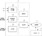
図2に示すように、制御端末3は、制御部31及びインターフェースを備える。インターフェースは、マイコンにより制御され、開閉器102、電力機器101及び中央サーバ2に対する信号の送受信を担う。このインターフェースは、電気量入力部32、外部条件入力部33、出力部34及び伝送部35である。電気量入力部32には変流器103及び計器用変圧器104から電気量情報が入力される。外部条件入力部33には開閉器102や電力機器101から外部条件情報が入力される。伝送部35は、中央サーバ2に対して状況情報6を送信する。また伝送部35は、中央サーバ2から指令信号を受信する。出力部34は、開閉器102に向けてトリップ信号又は投入信号を出力し、外部機器に向けてオン又はオフの制御信号を出力する。
制御部31は、マイコン及びリレースイッチの回路である。中央サーバ2から入力された指令信号に従い、制御端末3と同じ端子に設置された開閉器102を制御し、制御端末3と同じ区間に備えられる電力機器101を制御する。指令信号は、制御端末3ごとに特有であり、制御端末3の制御対象と制御内容が含まれる。制御内容は、例えば開閉器102のトリップ若しくは投入、又は電力機器101のオン若しくはオフである。
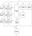
中央サーバ2は所謂コンピュータである。図3に示すように、中央サーバ2は、演算部21、プログラム記憶部22、データ記憶部23、プログラム生成部24、及びプログラム更新部25を備える。演算部21及びプログラム生成部24は、主にプロセッサとメモリにより構成され、プログラム更新部25は、主にプロセッサとメディアドライブにより構成され、プログラム記憶部22とデータ記憶部23は、HDDやSSD等のストレージにより構成される。
演算部21は、系統保護演算を行い、伝送部35を介して指令信号を制御端末3に送信する。系統保護演算は、事故検出演算と制御シーケンス演算に大別される。事故検出演算では、事故区間と事故様相を検出する。制御シーケンス演算では、制御対象を事前決定し、制御端末3の指令信号を生成する。事故検出演算及び制御シーケンス演算では、伝送部35を介して受信した状況情報6及びデータ記憶部23の各種の整定値及び設定値をパラメータとする。
メモリには、各区間に適した各種演算プログラム7aがロードされる。より詳細には、各区間での事故発生の検出、事故様相の検出、及び開閉器102と電力機器101の制御に適した各種演算プログラム7aがロードされる。例えば、事故の発生に対して送電線機器を保護する演算プログラム7aと、事故の発生に対して変圧機器を保護する演算プログラム7aが各々ロードされる。プロセッサが各演算プログラム7aを並行処理することで、中央サーバ2は、各区間に特有の系統保護演算を行う各演算部21を区間ごとに備える。
プログラム記憶部22には各種各内容のプログラム部品71が記憶されている。プログラム部品71は、図4に示すように、演算プログラム7aの部品であり、実行ファイル及び共有ライブラリである。共有ライブラリは、一部又は全部の区間に共通の系統保護演算内容に合わせて共用できるコード部分が記述されたプログラム部品71であり、複数の実行ファイルで同時に共用される。
プログラム生成部24は、プログラム部品71を各区間の系統保護演算内容に合わせて組み合わせることで各演算プログラム7aを生成し、メモリにロードする。一の実行ファイルに対して一種又は複数種の共用ライブラリがリンクされる。共用ライブラリは静的にリンクされても動的にリンクされてもよい。
プログラム更新部25は、プログラム記憶部22に記憶されているプログラム部品71を個別に更新する。メディアドライブには、新しいプログラム部品71を記憶したメディアが挿入される。ライブラリ更新部は、メディアから新しいプログラム部品71を読み出し、プログラム記憶部22に記憶された同名の古いプログラム部品71を新しいプログラム部品71に置き換える。
プログラム生成部24は、更新されたプログラム部品71を再度リンクし直す。そのため、共有ライブラリは、演算部21によるプログラム処理開始時に動的リンクされるダイナミックライブラリが望ましいが、これに限られない。
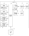
図5は、この系統保護制御システム1によるプログラムの更新動作を示す模式図である。図5に示すように、例えば変圧器を管轄する制御端末3に対する演算プログラムAと送電線を管轄する制御端末3に対する演算プログラムBには、共通部分Cが存在する。プログラム記憶部22には、演算プログラムAの特有部分を抽出した実行ファイル等のプログラム部品A1と、演算プログラムBの特有部分を抽出した実行ファイル等のプログラム部品B1と、共通部分Cを抽出した共有ライブラリ等のプログラム部品C1が記憶される。
共通部分Cの更新が発生したとする。プログラム更新部25は、プログラム記憶部22内のプログラム部品C1を新たなプログラム部品C2に置き換える。プログラム生成部24は、新たなプログラム部品C2をプログラム部品A1にリンクすることで、共通部分Cが更新された演算プログラムAを生成し、プログラム部品C2をプログラム部品B1にリンクすることで、共通部分Cが更新された演算プログラムBを生成する。
共通部分Cが更新された新たな演算プログラムAの実行により機能する演算部21は、変圧器を備える区画の系統保護演算を行う。また、共通部分Cが更新された新たな演算プログラムBの実行により機能する演算部21は、送電線を備える区画の系統保護演算を行う。
このように、演算プログラムAと演算プログラムBに対する共通部分Cの更新作業は、1度で済むものである。すなわち、この系統保護制御システム1は、各制御端末3と中央サーバ2とによりなる集中方式であり、中央サーバ2は、各演算プログラムを部品化して各種各内容のプログラム部品71を記憶し、区画に合致するプログラム部品71を組み合わせることで、系統保護の演算プログラム7aを区画ごとに生成するようにした。これにより、各制御端末3に保守員が赴いて更新作業をする必要はなく、更に制御端末3ごとに独立した演算プログラム7aの更新作業を、共通部分であれば1度で済ませることができ、プログラム更新作業の効率が向上する。
(第2の実施形態)
次に、第2の実施形態に係る系統保護制御システム1について図面を参照しつつ詳細に説明する。第1の実施形態と同一構成及び同一機能については同一符号を付して詳細な説明を省略する。
次に、第2の実施形態に係る系統保護制御システム1について図面を参照しつつ詳細に説明する。第1の実施形態と同一構成及び同一機能については同一符号を付して詳細な説明を省略する。
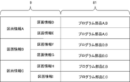
図6に示すように、プログラム生成部24は、選択部品判定部241とテーブル記憶部242を備える。テーブル記憶部242は、各区画の系統保護演算に適切なプログラム部品71を示すテーブル8を記憶している。図7に示すように、テーブル8には、各種区画情報9の組み合わせ毎に、適切なプログラム部品71を識別する識別情報81が関連付けられている。
区画情報9は、区画の構成や性質を示す情報であり、500kVや275kV等の区画の電圧、区画の電気量情報を計測するCT比やVT比、区画が送電線設備を備える場合の送電線の距離とインピーダンス、変圧器の容量、変圧器の結線態様、単母線や複母線や1-1/2母線等の母線の態様である。例えば、テーブル8には、単母線に適切なプログラム部品71が示され、また複母線に適切なプログラム部品71が示されている。
選択部品判定部241は、入力された区画情報9とテーブル記憶部242のテーブル8を参照して、選択されたプログラム部品71の適否を判定する。区画情報9は、ユーザ端末5の操作により中央サーバ2に入力される。ユーザ端末5は、制御端末3のマンマシンインターフェース、中央サーバ2のマンマシンインターフェース、制御端末3と同じローカルネットワークに接続された他のコンピュータ端末、又は中央サーバ2と同じローカルネットワークに接続された他のコンピュータである。
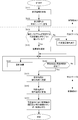
図8は、選択部品判定部241の動作を示すフローチャートである。まず、ユーザ端末5と中央サーバ2との接続が確立される(ステップS01)。ユーザ端末5と中央サーバ2とは、例えばTCP/IPプロトコルにより通信する。ユーザ端末5が中央サーバ2のマンマシンインターフェースである場合には、接続の確立は必要ない。
ユーザ端末5と中央サーバ2との接続が確立すると、プログラム生成部24は、ユーザ端末5との接続が許可されているか確認する(ステップS02)。このとき、制御端末3と中央サーバ2の接続確認も行う。許可判定は、例えばIDとパスワードの照合である。または、制御端末3のマンマシンインターフェースがユーザ端末5の場合、許可判定は、例えば制御端末3のIPアドレスである。許可判定に利用されるID、パスワード、又はIPアドレス等の情報は、予め設定しておく。尚、ユーザ端末5が制御端末3のインターフェースである場合、実際には、制御端末3と中央サーバ2との接続が確立され、制御端末3に対する接続許可が確認される。
接続が確立し、また接続が許可されると、管理者はユーザ端末5に、保護する区画の区画情報9を入力する(ステップS03)。更に管理者はユーザ端末5に、演算プログラム7aのプログラム部品71を選択する選択情報10を入力する(ステップS04)。選択情報10は、演算プログラム7aを構成するプログラム部品71の組み合わせを示し、例えばプログラム部品71の識別情報81の群である。中央サーバ2がプログラム部品71のリストをユーザ端末5に送信し、リストからプログラム部品71を選択するようにしてもよい。
入力された区画情報9と選択情報10は中央サーバ2に送信される。中央サーバ2において、選択部品判定部241は、テーブル8を参照して、区画情報9の組み合わせに関連付けられたプログラム部品71の識別情報81の群を抽出する(ステップS05)。そして、選択部品判定部241は、抽出した識別情報81の群と選択情報10を構成する識別情報81の群とを比較する(ステップS06)。比較の結果、双方の識別情報81の群に相違がある場合(ステップS06,No)、プログラム部品71の選択誤りを報知するメッセージをユーザ端末5に送信し(ステップS07)、ステップS04に戻って選択情報10の再入力を待つ。
テーブル8から抽出した識別情報81の群と選択情報10を構成する識別情報81の群との間に相違がない場合(ステップS06,Yes)、次に管理者はユーザ端末5に、系統保護演算のための整定値及び設定値を入力する(ステップS08)。以上により、プログラム部品71が正しく選択され、整定値及び設定値が入力されると、プログラム生成部24は、整定値と設定値を該当変数の代入値として、プログラム部品71から演算プログラム7aを生成する(ステップS09)。この演算プログラム7aの実行により演算部21が機能し、対象区画のための系統保護演算を開始する(ステップS10)。
このように、本実施形態の系統保護制御システム1では、プログラム部品71の選択情報10を中央サーバ2に送信するユーザ端末5を備えるようにし、プログラム生成部24は、選択情報10に従ってプログラム部品71を組み合わせるようにした。プログラム部品71の種類によっては、系統保護演算に適当なプログラム部品71が1つとは限らない。そのため、管理者側で適切なプログラム部品71が選択されることで、演算プログラム7aをプログラム部品71に分割する方式の実効性が高まる。
また、ユーザ端末5は区画情報9を中央サーバ2に更に送信する。そして、プログラム生成部24は、区画情報9と適切なプログラム部品71との組み合わせを示すテーブル8を記憶しておき、ユーザ端末5が送信した区画情報9と選択情報10とテーブル8に基づき、選択情報10の適否を判定するようにした。これにより、誤った系統保護演算が行われる事態を回避でき、この系統保護制御システム1の信用性及び安全性が高まる。
(変形例)
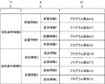
プログラム部品71の適正判定では、契約条件情報11を加味するようにしてもよい。図9に示すように、テーブル8には、区画情報9と契約条件情報11の組み合わせに対して、適切なプログラム部品71の識別情報81の群が関連付けられている。契約条件情報11は、中央サーバ2に系統保護演算を依頼するユーザの契約条件を示し、例えば課金状況である。契約条件情報11は、契約条件を間接的に示すユーザ情報であってもよい。この契約条件情報11は、ユーザ端末5を用いたユーザ登録によって予め中央サーバ2側に記憶しておく。
プログラム部品71の適正判定では、契約条件情報11を加味するようにしてもよい。図9に示すように、テーブル8には、区画情報9と契約条件情報11の組み合わせに対して、適切なプログラム部品71の識別情報81の群が関連付けられている。契約条件情報11は、中央サーバ2に系統保護演算を依頼するユーザの契約条件を示し、例えば課金状況である。契約条件情報11は、契約条件を間接的に示すユーザ情報であってもよい。この契約条件情報11は、ユーザ端末5を用いたユーザ登録によって予め中央サーバ2側に記憶しておく。
中央サーバ2は、許可判定に利用される情報と紐付けて契約条件情報11を管理しておく。プログラム生成部24は、ユーザ端末5との接続許可の確認の際に入力されたIPアドレス等の情報に紐付けられた契約条件情報11を利用すればよい。プログラム生成部24は、この契約条件情報11と区画情報9の組み合わせに対するプログラム部品71が選択情報10と合致するか判定する。
このように、プログラム記憶部22には、区画情報9の観点では適切な同種のプログラム部品71を複数内容記憶しておくことが可能である。そして、契約条件によって、使用可能なプログラム部品71を制限するようにしてもよい。
(第3の実施形態)
次に、第3の実施形態に係る系統保護制御システム1について図面を参照しつつ詳細に説明する。第1又は第2の実施形態と同一構成及び同一機能については同一符号を付して詳細な説明を省略する。
次に、第3の実施形態に係る系統保護制御システム1について図面を参照しつつ詳細に説明する。第1又は第2の実施形態と同一構成及び同一機能については同一符号を付して詳細な説明を省略する。
図10に示すように、プログラム記憶部22には、代替演算プログラム7bのプログラム部品71が更に記憶されている。代替演算プログラム7bは、演算プログラム7aと演算アルゴリズムが異なり、系統保護演算に必要とする状況情報6の種類が演算プログラム7aと異なる。この代替演算プログラム7bのプログラム部品71も実行ファイルと共有ライブラリによりなる。
また、図11に示すように、中央サーバ2は、プログラム選定部26と、代替演算プログラム7bの実行により機能する代替演算部27を更に備える。プログラム選定部26は、制御端末3から送信された状況情報6に応じて、適切な演算部21又は代替演算部27を選定する。選定の最優先は、状況情報6を送信した制御端末3に合わせて生成された演算プログラム7aの演算部21である。
但し、送信された状況情報6が当該演算部21に不適な場合、例えば状況情報6が不足する場合、プログラム選定部26は、状況情報6で系統保護演算が可能な代替演算部27を選定する。選定された演算部21又は代替演算部27は、制御端末3から送信された状況情報6と整定値と設定値をパラメータとして系統保護演算を行う。
図12は、この系統保護制御システム1の系統保護演算の動作を示すフローチャートである。演算プログラム7aの生成が終了し、制御端末3に対する演算機能として中央サーバ2が稼動を始めると、制御端末3は、変流器103、計器用変圧器104及び電力機器101から状況情報6を収集する(ステップS11)。制御端末3は、収集した状況情報6を中央サーバ2へ送信する(ステップS12)。
中央サーバ2では、プログラム選定部26により、生成した演算プログラム7aが要求する状況情報6が過不足無く揃っているか判断する(ステップS13)。プログラム選定部26は、例えば演算プログラム7aの該当変数の全てが状況情報6で初期化可能か判断すればよい。
状況情報6が過不足無く揃っている場合(ステップS13,Yes)、プログラム選定部26は、生成した演算プログラム7aにより機能する演算部21を選定する(ステップS14)。選定処理は、例えば、整定値及び設定値を渡し、演算プログラム7aを起動させればよい。
選定により稼働した演算部21は、状況情報6等をパラメータとして、制御対象を想定の事故様相ごとに事前演算する(ステップS15)。この事前演算は、所定間隔で繰り返し、制御対象を最新結果に更新していく。また、この演算部21は、状況情報6等により事故発生と事故様相とを検出する(ステップS16)。この検出も所定間隔で繰り返される。
事故発生と事故様相を検出した場合(ステップS16,Yes)、選定された演算部21は、伝送部35を介して事前演算の結果を含む指令信号を制御端末3に送信する(ステップS17)。制御端末3は、指令信号を受けて(ステップS18)、指令信号に従って開閉器102の開閉及び電力機器101のオンオフ制御を行う(ステップS19)。
一方、状況情報6が不足している場合(ステップS13,No)、プログラム選定部26は、代替演算プログラム7bに基づく代替演算部27を選定する(ステップS20)。この選定処理において、プログラム選定部26は、代替演算部27ごとに必要パラメータの種類を予め記憶しておき、送信されてきた状況情報6が必要パラメータに合致する代替演算部27を検索すればよい。代替演算部27が選定されると、その代替演算部27がステップS15以降の系統保護演算と指令信号の出力動作を実行する。
このように、プログラム記憶部22は、系統保護演算の代替演算プログラム7bを更に記憶し、プログラム選定部26により、送信されてきた状況情報6に対して適切な演算部21又は代替演算部27を選定するようにした。
例えば、電圧値が含まれていない等の不足した状況情報6により演算部21が系統保護演算を実行すると、誤動作や誤不動作を生じ、開閉器102や電力機器101に対して誤った制御を実施する虞がある。しかしながら、この系統保護制御システム1では、状況情報6が演算プログラム7aの要求に合致していない場合には、その状況情報6に合った代替演算プログラム7aによって系統保護演算を実行するため、誤動作の発生を抑制でき、信頼性を高めることができる。
(第4の実施形態)
次に、第4の実施形態に係る系統保護制御システム1について図面を参照しつつ詳細に説明する。第1乃至第3の実施形態と同一構成及び同一機能については同一符号を付して詳細な説明を省略する。
次に、第4の実施形態に係る系統保護制御システム1について図面を参照しつつ詳細に説明する。第1乃至第3の実施形態と同一構成及び同一機能については同一符号を付して詳細な説明を省略する。
図13に示すように、中央サーバ2はプログラム転送部28を備える。プログラム転送部28は、伝送部35を介して演算プログラム7aを制御端末3に送信する。送信タイミングは、演算プログラム7aの最初の生成時と、演算プログラム7aを構成するプログラム部品71の更新時である。
図14に示すように、制御端末3は、演算プログラム記憶部36とプログラム更新部37と実行判定部38と演算部39を備える。演算プログラム記憶部36は、マイコンのメモリであり、中央サーバ2から送信されてきた演算プログラムを記憶する。プログラム更新部37は、中央サーバ2のプログラム転送部28からの接続要求に応じて、演算プログラム7aを受信し、演算プログラム記憶部36の演算プログラム7aを更新する。
実行判定部38は、演算プログラム7aの実行要否を判定する。実行要否の判定基準は、中央サーバ2との接続確立可否である。演算部39は、演算プログラム記憶部36に記憶された演算プログラム7aをマイコンが実行することにより機能し、系統保護演算を行い、制御部31に指令信号を出力する。
図15は、実行判定部38の実行要否判定の動作を示すフローチャートである。実行判定部38は、伝送部35による状況情報6等の送信を監視する。伝送部35が中央サーバ2との接続確立に成功せずにタイムアウトすると(ステップS31,Yes)、実行判定部38は、演算プログラム7aを起動させる(ステップS32)。演算プログラム7aの起動により演算部39が機能し(ステップS33)、系統保護演算を行い(ステップS34)、事故検出及び事故様相の検出がなされると(ステップS35,Yes)、事前演算により得た指令信号を制御部31に出力する(ステップS36)。制御部31は、指令信号に従って開閉器102及び電力機器101を制御する(ステップS37)。
この系統保護制御システム1によれば、中央サーバ2側が系統保護演算を行い、事故検出等を行い、開閉器102等の制御指令を発するが、中央サーバ2との間で通信途絶状態となった場合であっても、制御端末3側で系統保護演算をバックアップし、自立的に事故発生及び事故様相の検出、目的制御量と制御対象の事前演算、及び開閉器102等の制御を達成できる。従って、通信網4の障害や中央サーバ2の不具合に対してもフェイルセーフ機能が発揮され、事故除去を行うことができ、系統保護制御システム1の信頼性を向上させることができる。
(その他の実施形態)
本明細書においては、本発明に係る実施形態を説明したが、この実施形態は例として提示したものであって、発明の範囲を限定することを意図していない。以上のような実施形態は、その他の様々な形態で実施されることが可能であり、発明の範囲を逸脱しない範囲で、種々の省略や置き換え、変更を行うことができる。実施形態やその変形は、発明の範囲や要旨に含まれると同様に、請求の範囲に記載された発明とその均等の範囲に含まれるものである。
本明細書においては、本発明に係る実施形態を説明したが、この実施形態は例として提示したものであって、発明の範囲を限定することを意図していない。以上のような実施形態は、その他の様々な形態で実施されることが可能であり、発明の範囲を逸脱しない範囲で、種々の省略や置き換え、変更を行うことができる。実施形態やその変形は、発明の範囲や要旨に含まれると同様に、請求の範囲に記載された発明とその均等の範囲に含まれるものである。
1 系統保護制御システム
2 中央サーバ
21 演算部
22 プログラム記憶部
23 データ記憶部
24 プログラム生成部
241 選択部品判定部
242 テーブル記憶部
25 プログラム更新部
26 プログラム選定部
27 代替演算部
28 プログラム転送部
3 制御端末
31 制御部
32 電気量入力部
33 外部条件入力部
34 出力部
35 伝送部
36 演算プログラム記憶部
37 プログラム更新部
38 実行判定部
39 演算部
4 通信網
5 ユーザ端末
6 状況情報
7a 演算プログラム
7b 代替演算プログラム
71 プログラム部品
8 テーブル
81 識別情報
9 区画情報
10 選択情報
11 契約条件情報
100 電力系統
101 電力機器
102 開閉器
103 変流器
104 計器用変圧器
2 中央サーバ
21 演算部
22 プログラム記憶部
23 データ記憶部
24 プログラム生成部
241 選択部品判定部
242 テーブル記憶部
25 プログラム更新部
26 プログラム選定部
27 代替演算部
28 プログラム転送部
3 制御端末
31 制御部
32 電気量入力部
33 外部条件入力部
34 出力部
35 伝送部
36 演算プログラム記憶部
37 プログラム更新部
38 実行判定部
39 演算部
4 通信網
5 ユーザ端末
6 状況情報
7a 演算プログラム
7b 代替演算プログラム
71 プログラム部品
8 テーブル
81 識別情報
9 区画情報
10 選択情報
11 契約条件情報
100 電力系統
101 電力機器
102 開閉器
103 変流器
104 計器用変圧器
Claims (11)
- 電力系統内の各区画に設置され、開閉器を含む機器を制御する各制御端末と、
演算により前記各区画の事故を検出し、制御対象を決定し、事故区間の前記制御端末に指令信号を出力する中央サーバと、
を備え、
前記中央サーバは、
各種各内容のプログラム部品を記憶するプログラム記憶部と、
前記区画に合わせて前記プログラム部品を組み合わせることで、前記演算のための演算プログラムを区画ごとに生成するプログラム生成部と、
前記各演算プログラムに基づき、前記演算を行う演算部と、
を含むこと、
を特徴とする系統保護制御システム。 - 前記プログラム部品の選択情報を前記中央サーバに送信するユーザ端末を備え、
前記プログラム生成部は、前記選択情報に従って前記プログラム部品を組み合わせること、
を特徴とする請求項1記載の系統保護制御システム。 - 前記ユーザ端末と前記制御端末は同じローカルネットワークに属すること、
を特徴とする請求項2記載の系統保護制御システム。 - 前記ユーザ端末と前記中央サーバは同じローカルネットワークに属すること、
を特徴とする請求項2記載の系統保護制御システム。 - 前記ユーザ端末は、前記区画の区画情報を前記中央サーバに更に送信し、
前記プログラム生成部は、
前記区画情報と適切なプログラム部品との関連付けを示すテーブルを記憶するテーブル記憶部と、
前記ユーザ端末が送信した前記区画情報と前記選択情報と前記テーブルに基づき、前記選択情報の適否を判定する適正部品判定部と、
を含むこと、
を特徴とする請求項2乃至4の何れかに記載の系統保護制御システム。 - 前記テーブル記憶部は、前記区画情報と前記区画に対する契約条件情報の組み合わせに対して前記適切なプログラム部品との関連付けを示す前記テーブルを記憶し、
前記適正部品判定部は、前記契約条件情報を更に加味して前記適否を判定すること、
を特徴とする請求項5記載の系統保護制御システム。 - 前記制御端末は、前記区画の状況情報を前記中央サーバに送信し、
前記プログラム記憶部は、前記演算の代替プログラムを更に記憶し、
前記中央サーバは、
前記代替プログラムに基づき、前記演算を行う代替演算部と、
前記制御端末から送信されてきた状況情報に合致する前記演算部又は前記代替演算部を選定するプログラム選定部を更に備え、
前記プログラム選定部により選定された前記演算部又は前記代替演算部が前記演算を実行すること、
を特徴とする請求項1乃至6の何れかに記載の系統保護制御システム。 - 前記制御端末は、
前記プログラム生成部により生成された演算プログラムを受信する伝送部と、
前記伝送部が受信した演算プログラムを記憶する演算プログラム記憶部と、
前記中央サーバとの接続確立可否を判定し、前記中央サーバと接続不能と判定すると、前記演算プログラムを起動する実行判定部と、
前記実行判定部に起動された前記演算プログラムにより機能し、前記演算を行う演算部と、
を含むこと、
を特徴とする請求項1乃至7の何れかに記載の系統保護制御システム。 - 前記プログラム部品の一部は、共有ライブラリであること、
を特徴とする請求項1乃至8の何れかに記載の系統保護制御システム。 - 前記区画情報は、前記区画の構成や性質を示すこと、
を特徴とする請求項5記載の系統保護制御システム。 - 前記状況情報は、少なくとも前記区画の電気量情報と前記区画が備える電力機器のオンオフ情報の一方又は両方を含むこと、
を特徴とする請求項7記載の系統保護制御システム。
Applications Claiming Priority (2)
| Application Number | Priority Date | Filing Date | Title |
|---|---|---|---|
| JP2015-107760 | 2015-05-27 | ||
| JP2015107760A JP6470110B2 (ja) | 2015-05-27 | 2015-05-27 | 系統保護制御システム |
Publications (1)
| Publication Number | Publication Date |
|---|---|
| WO2016189760A1 true WO2016189760A1 (ja) | 2016-12-01 |
Family
ID=57392981
Family Applications (1)
| Application Number | Title | Priority Date | Filing Date |
|---|---|---|---|
| PCT/JP2015/079078 Ceased WO2016189760A1 (ja) | 2015-05-27 | 2015-10-14 | 系統保護制御システム |
Country Status (2)
| Country | Link |
|---|---|
| JP (1) | JP6470110B2 (ja) |
| WO (1) | WO2016189760A1 (ja) |
Cited By (1)
| Publication number | Priority date | Publication date | Assignee | Title |
|---|---|---|---|---|
| CN112653079A (zh) * | 2020-12-23 | 2021-04-13 | 广东电网有限责任公司 | 一种基于模板匹配的保护定值下装方法和装置 |
Citations (3)
| Publication number | Priority date | Publication date | Assignee | Title |
|---|---|---|---|---|
| JPH10108348A (ja) * | 1996-09-27 | 1998-04-24 | Fuji Electric Co Ltd | 保護リレー |
| JPH10257661A (ja) * | 1996-12-03 | 1998-09-25 | Toshiba Corp | 監視制御システムとこのシステムを実行するためのプログラムを記録した記録媒体 |
| JP2002233059A (ja) * | 2001-01-29 | 2002-08-16 | Toshiba Corp | 変電所遠隔監視制御保護システム |
-
2015
- 2015-05-27 JP JP2015107760A patent/JP6470110B2/ja active Active
- 2015-10-14 WO PCT/JP2015/079078 patent/WO2016189760A1/ja not_active Ceased
Patent Citations (3)
| Publication number | Priority date | Publication date | Assignee | Title |
|---|---|---|---|---|
| JPH10108348A (ja) * | 1996-09-27 | 1998-04-24 | Fuji Electric Co Ltd | 保護リレー |
| JPH10257661A (ja) * | 1996-12-03 | 1998-09-25 | Toshiba Corp | 監視制御システムとこのシステムを実行するためのプログラムを記録した記録媒体 |
| JP2002233059A (ja) * | 2001-01-29 | 2002-08-16 | Toshiba Corp | 変電所遠隔監視制御保護システム |
Cited By (1)
| Publication number | Priority date | Publication date | Assignee | Title |
|---|---|---|---|---|
| CN112653079A (zh) * | 2020-12-23 | 2021-04-13 | 广东电网有限责任公司 | 一种基于模板匹配的保护定值下装方法和装置 |
Also Published As
| Publication number | Publication date |
|---|---|
| JP2016226092A (ja) | 2016-12-28 |
| JP6470110B2 (ja) | 2019-02-13 |
Similar Documents
| Publication | Publication Date | Title |
|---|---|---|
| CN102273037B (zh) | 混合配电网电力恢复控制 | |
| De La Ree et al. | Catastrophic failures in power systems: causes, analyses, and countermeasures | |
| JP5985198B2 (ja) | 変電所自動化システム及び端末の自動認識方法 | |
| US9965013B1 (en) | Switchgear controller device | |
| CN109840104A (zh) | 用于提供设备的固件更新的方法 | |
| BRPI0819935B1 (pt) | método de restaurar energia em uma rede de distribuição de energia | |
| BR112012018015B1 (pt) | Sistema para reconfiguração automatizada de um sistema de distribuição de eletricidade | |
| US10476268B2 (en) | Optimized decoupling and load shedding | |
| CN107659948B (zh) | 一种控制ap接入的方法及装置 | |
| Damchi et al. | Preprocessing of distance and directional overcurrent relays coordination problem considering changes in network topology | |
| WO2020122039A1 (ja) | データ管理方法、データ管理システム及びプログラム | |
| US8766809B2 (en) | Apparatus and method for correcting error of acquired data | |
| Zhu et al. | Reliability and vulnerability assessment of interconnected ICT and power networks using complex network theory | |
| Davidson et al. | Exploiting multi-agent system technology within an autonomous regional active network management system | |
| CN104503405B (zh) | 基于scada系统的监控方法、装置和系统 | |
| Manson et al. | Cybersecurity for protection and control systems: An overview of proven design solutions | |
| JP6470110B2 (ja) | 系統保護制御システム | |
| Caicedo et al. | Revolutionizing protection dynamics in microgrids: Local validation environment and a novel global management control through multi-agent systems | |
| US9823721B1 (en) | Switchgear controller device | |
| Brand et al. | Resilience of Digitalised Power Systems—Challenges and Solutions | |
| Mishra et al. | Proposing a framework for resilient active distribution systems using withstand, respond, adapt, and prevent element | |
| Bhattarai et al. | Blockchain for fault-tolerant grid operations | |
| KR102939057B1 (ko) | 배전 장치의 스위칭 장치의 스위칭 상태를 최적화하기 위한 시스템 및 방법 | |
| US10924345B2 (en) | Method for changing the configuration of connected networks | |
| US20200117440A1 (en) | Hierarchical equipment software update for an electrical distribution grid |
Legal Events
| Date | Code | Title | Description |
|---|---|---|---|
| 121 | Ep: the epo has been informed by wipo that ep was designated in this application |
Ref document number: 15893392 Country of ref document: EP Kind code of ref document: A1 |
|
| NENP | Non-entry into the national phase |
Ref country code: DE |
|
| 122 | Ep: pct application non-entry in european phase |
Ref document number: 15893392 Country of ref document: EP Kind code of ref document: A1 |