WO2016189736A1 - 光学ユニット、撮像装置および内視鏡 - Google Patents
光学ユニット、撮像装置および内視鏡 Download PDFInfo
- Publication number
- WO2016189736A1 WO2016189736A1 PCT/JP2015/065433 JP2015065433W WO2016189736A1 WO 2016189736 A1 WO2016189736 A1 WO 2016189736A1 JP 2015065433 W JP2015065433 W JP 2015065433W WO 2016189736 A1 WO2016189736 A1 WO 2016189736A1
- Authority
- WO
- WIPO (PCT)
- Prior art keywords
- coils
- optical unit
- magnet
- magnetic sensor
- holding
- Prior art date
Links
Images


Classifications
-
- A—HUMAN NECESSITIES
- A61—MEDICAL OR VETERINARY SCIENCE; HYGIENE
- A61B—DIAGNOSIS; SURGERY; IDENTIFICATION
- A61B1/00—Instruments for performing medical examinations of the interior of cavities or tubes of the body by visual or photographical inspection, e.g. endoscopes; Illuminating arrangements therefor
-
- G—PHYSICS
- G02—OPTICS
- G02B—OPTICAL ELEMENTS, SYSTEMS OR APPARATUS
- G02B23/00—Telescopes, e.g. binoculars; Periscopes; Instruments for viewing the inside of hollow bodies; Viewfinders; Optical aiming or sighting devices
- G02B23/24—Instruments or systems for viewing the inside of hollow bodies, e.g. fibrescopes
-
- G—PHYSICS
- G02—OPTICS
- G02B—OPTICAL ELEMENTS, SYSTEMS OR APPARATUS
- G02B7/00—Mountings, adjusting means, or light-tight connections, for optical elements
- G02B7/02—Mountings, adjusting means, or light-tight connections, for optical elements for lenses
- G02B7/04—Mountings, adjusting means, or light-tight connections, for optical elements for lenses with mechanism for focusing or varying magnification
- G02B7/08—Mountings, adjusting means, or light-tight connections, for optical elements for lenses with mechanism for focusing or varying magnification adapted to co-operate with a remote control mechanism
-
- H—ELECTRICITY
- H02—GENERATION; CONVERSION OR DISTRIBUTION OF ELECTRIC POWER
- H02K—DYNAMO-ELECTRIC MACHINES
- H02K33/00—Motors with reciprocating, oscillating or vibrating magnet, armature or coil system
- H02K33/18—Motors with reciprocating, oscillating or vibrating magnet, armature or coil system with coil systems moving upon intermittent or reversed energisation thereof by interaction with a fixed field system, e.g. permanent magnets
Definitions
- the present invention relates to an optical unit, an imaging apparatus, and an endoscope that drive a lens group using a voice coil motor.
- a technique using a voice coil motor as an actuator for driving a moving lens group such as a zoom lens and a focus lens is known (see, for example, Patent Document 1).
- a magnetic sensor is provided to accurately detect the position of the moving lens group.
- a voice coil motor configured using a plurality of coils is also known (see, for example, Patent Document 2).
- the present invention has been made in view of the above, and provides an optical unit, an imaging apparatus, and an endoscope that can detect the position of a movable part with high accuracy even when a plurality of coils are used. For the purpose.
- an optical unit holds a lens group and is movable with respect to a predetermined fixing part along the optical axis direction of the lens group. And a first magnet that is magnetically polarized in a direction intersecting the optical axis and provided in one of the fixed portion and the holding portion, and the first magnet of the fixed portion and the holding portion is provided.
- a plurality of coils that are provided on the side that is not provided and receive a force in the direction of the optical axis by a magnetic field generated by the first magnet when a current flows; and one of the fixed portion and the holding portion A second magnet provided on a side of the plurality of coils provided within a range in which the second magnet is not provided among the fixed portion and the holding portion, and the holding portion is movable.
- Two magnetic field directions It is disposed at a position capable of taking a state mutually off, characterized by comprising a magnetic sensor for detecting a magnetic field formed by the second magnet.
- An image pickup apparatus includes the above-described optical unit and an image pickup element that receives the light collected by the optical unit and converts the light into an electric signal.
- An endoscope according to the present invention is an endoscope that is inserted into a subject and observes the inside of the subject, the imaging device described above, and an insertion portion that is inserted into the subject. It is provided with.
- the position of the movable part can be detected with high accuracy even when a plurality of coils are used.
- FIG. 1 is a perspective view showing a configuration of an optical unit according to Embodiment 1 of the present invention.
- 2 is a plan view in the direction of arrow A in FIG.
- FIG. 3 is a diagram for schematically explaining the installation position of the magnetic sensor provided in the optical unit according to Embodiment 1 of the present invention.
- FIG. 4 is a plan view showing the configuration of the main part of the optical unit according to Modification 1-1 of Embodiment 1 of the present invention.
- FIG. 5 is a diagram for schematically explaining the installation position of the magnetic sensor provided in the optical unit according to Modification 1-1 of Embodiment 1 of the present invention.
- FIG. 6 is a plan view showing the configuration of the main part of the optical unit according to Modification 1-2 of Embodiment 1 of the present invention.
- FIG. 7 is a plan view showing the configuration of the main part of the optical unit according to Modification 1-3 of Embodiment 1 of the present invention.
- FIG. 8 is a perspective view showing the configuration of the optical unit according to Embodiment 2 of the present invention.
- FIG. 9 is a plan view in the direction of arrow B in FIG.
- FIG. 10 is a plan view showing the configuration of the main part of the optical unit according to Modification 2-1 of Embodiment 2 of the present invention.
- FIG. 11 is a plan view showing the configuration of the main part of the optical unit according to Modification 2-2 of Embodiment 2 of the present invention.
- FIG. 12 is a plan view showing the configuration of the main part of the optical unit according to Modification 2-3 of Embodiment 2 of the present invention.
- FIG. 13 is a plan view showing the configuration of the main part of the optical unit according to Embodiment 3 of the present invention.
- FIG. 14 is a plan view showing the configuration of the main part of the optical unit according to Embodiment 4 of the present invention.
- FIG. 15 is a diagram illustrating a configuration of an endoscope system including the endoscope according to the fifth embodiment of the present invention.
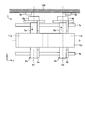
- FIG. 1 is a perspective view showing a configuration of an optical unit according to Embodiment 1 of the present invention.
- 2 is a plan view in the direction of arrow A in FIG.
- the optical unit 1 shown in these drawings is provided in an imaging apparatus and forms at least a part of an optical system that collects light from a subject and forms an image on a light receiving surface of an imaging element.
- the optical unit 1 includes a portion that is movable with respect to the main body 100 of the imaging apparatus, which is a predetermined fixing portion, and a portion that is fixed to the main body 100.
- the two movable parts 2a and 2b that form a part that can move with respect to the main body 100 in the optical unit 1 will be described.
- the movable portion 2a includes a lens 3a, a holding portion 4a that holds the lens 3a, a coil 5a that is provided in the holding portion 4a and wound in a rectangular shape with the optical axis O of the lens 3a as a central axis, and a holding portion 4a. And a position detecting magnet (second magnet) 6a provided on the side portion of the head. Shafts 7a and 7b that extend parallel to the optical axis of the lens 3a and are fixed to the main body 100 pass through the holding portion 4a. For this reason, the moving direction of the holding
- the holding unit 4a holds one lens 3a, but the holding unit 4a may hold a lens group including a plurality of lenses whose optical axes coincide with each other.
- the shafts 7a and 7b describe only the intermediate portion. The description method of shaft 7a, 7b is the same also in drawing referred below.
- the movable part 2b has a lens 3b, a holding part 4b, a coil 5b, and a position detection magnet (second magnet) 6b.
- the optical axis of the lens 3b coincides with the optical axis O of the lens 3a.
- Shafts 7a and 7b pass through holding portion 4b.
- the moving direction of the holding portion 4b is regulated by the shafts 7a and 7b in a direction parallel to the optical axis direction of the lens 3b.
- the holding unit 4b may hold a lens group including a plurality of lenses.
- the direction of the current flowing through the coil 5a is opposite to the direction of the current flowing through the coil 5b.
- Magnetic sensors 8a and 8b are fixed to the main body 100 in the vicinity of the position detection magnets 6a and 6b provided in the movable portions 2a and 2b, respectively.
- the magnetic sensors 8a and 8b are realized using, for example, a Hall element or a magnetoresistive effect element (MR element), and detect the magnetic fields generated by the position detection magnets 6a and 6b, respectively.
- MR element magnetoresistive effect element
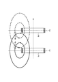
- FIG. 3 is a diagram for schematically explaining the installation positions of the magnetic sensors 8a and 8b, and is a schematic diagram viewed in a plane passing through the central axes of the coils 5a and 5b.
- the currents flowing through the two coils 5a and 5b are in opposite directions. Therefore, when viewed in the plane shown in FIG. 3, the magnetic field generated by the current flowing through the coil 5a is counterclockwise with respect to the coil 5a, whereas the magnetic field generated by the current flowing through the coil 5b is applied to the coil 5b. In contrast, it is clockwise.
- the magnetic sensors 8a and 8b are arranged at positions where magnetic fields generated by currents flowing through the two coils 5a and 5b arranged along the optical axis cancel each other.
- the magnetic sensor 8a is provided in a region farther from the coil 5b than a plane P1 passing through the center of the coil 5a and orthogonal to the central axis O of the coil 5a.
- the magnetic sensor 8b is provided in a region farther from the coil 5a than a plane P2 that passes through the center of the coil 5b and is orthogonal to the central axis O of the coil 5b.
- the magnetic sensors 8a and 8b are located outside the region sandwiched between the plane P1 and the plane P2.
- the positional relationship shown in FIG. 3 is merely an example.
- the magnetic sensors 8a and 8b only need to be arranged at positions where the state shown in FIG. 3 can be taken within a range in which the holding portions 4a and 4b can move. Therefore, for example, only one of the magnetic sensors 8a and 8b may take the state shown in FIG.
- the detection results of the magnetic sensors 8a and 8b are sent to the control unit 9.
- the controller 9 calculates the positions of the movable parts 2a and 2b based on the detection results of the magnetic sensors 8a and 8b.
- the control unit 9 controls the driving of the drivers 10a and 10b according to the positions of the movable units 2a and 2b, thereby determining the current flowing from the driver 10a to the coil 5a and the current flowing from the driver 10b to the coil 5b, respectively.
- the control unit 9 is configured using a CPU (Central Processing Unit) or the like, and controls the operation of the optical unit 1 in an integrated manner.
- the control unit 9 and the drivers 10 a and 10 b are fixed to the main body 100.
- Magnets (first magnets) 11a and 12a are respectively provided on the outer peripheral sides of two opposite sides of the four sides of the rectangle formed by the coil 5a.
- Magnets (first magnets) 11b and 12b are respectively provided on the outer peripheral sides of two opposing sides of the rectangular shape of the coil 5b.
- the magnets 11a and 11b are disposed on the inner peripheral surface side of the yoke 13a that intersects with the coils 5a and 5b, respectively.
- Magnets 12a and 12b circulate around coils 5a and 5b, respectively, and are arranged on the inner peripheral surface side of yoke 13b facing yoke 13a.
- the yoke 13a is made of iron or steel, and forms a magnetic circuit together with the magnets 11a and 11b.
- the yoke 13b is made of the same material as the yoke 13a and forms a magnetic circuit together with the magnets 12a and 12b.
- the yokes 13 a and 13 b are fixed to the main body 100.
- the magnets 11a, 11b, 12a, and 12b are magnetically polarized in the central axis direction of the coils 5a and 5b, in other words, in the direction orthogonal to the optical axis direction of the lenses 3a and 3b. More generally, the magnets 11a, 11b, 12a, and 12b need only be magnetically polarized in a direction that intersects the central axis direction of the coils 5a and 5b (the optical axis direction of the lenses 3a and 3b).
- the coil 5a, the magnets 11a and 12a, and the yokes 13a and 13b constitute a voice coil motor.
- the coil 5b, the magnets 11b and 12b, and the yokes 13a and 13b also constitute a voice coil motor.
- a voice coil motor can be configured without using the yokes 13a and 13b.
- the magnet 11a and the magnet 11b, and the magnet 12a and the magnet 12b may be integrated. These points are common to all embodiments described later.
- the optical unit 1 only needs to include at least one set of a magnetic sensor and a position detection magnet. That is, one of the magnetic sensors 8a and 8b can be replaced with other detection means. In this case, a position detecting magnet provided corresponding to the replaced magnetic sensor is not required. Since highly accurate position detection can be performed by using a magnetic sensor and a position detection magnet, the magnetic sensor and the position detection magnet can be used with respect to the movable part of the movable parts 2a and 2b that requires higher accuracy. It is preferable to provide a set.
- the magnetic sensors 8a and 8b cancel the directions of the magnetic fields generated by the currents flowing through the two coils 5a and 5b within the range in which the holding portions 4a and 4b can move. Since it exists in the position which can take a suitable state, the magnetic field which generate
- FIG. 4 is a plan view showing the configuration of the main part of the optical unit according to Modification 1-1 of Embodiment 1, and is a view seen from the same direction as the plan view shown in FIG. In the optical unit 1A shown in FIG. 4, currents in the same direction are passed through the coils 5a and 5b. Accordingly, in Modification 1-1, the installation positions of the magnetic sensors 8a and 8b are different from those in the first embodiment.
- FIG. 5 is a diagram for explaining the installation positions of the magnetic sensors 8a and 8b, and is a schematic diagram viewed in a plane passing through the central axes of the coils 5a and 5b.
- the currents flowing through the two coils 5a and 5b are in the same direction. Therefore, when viewed in the plane shown in FIG. 5, the magnetic field generated by the current flowing through the coil 5a is counterclockwise with respect to the coil 5a, and the magnetic field generated by the current flowing through the coil 5b is also counterclockwise with respect to the coil 5b. It is.
- the magnetic sensors 8a and 8b are arranged at positions where the magnetic fields generated by the currents flowing through the two coils 5a and 5b cancel each other.
- the magnetic sensor 8a is provided in a region closer to the coil 5b than to the plane P1.
- the magnetic sensor 8b is provided in a region closer to the coil 5a than the plane P2.
- the magnetic sensors 8a and 8b are located in a region sandwiched between the plane P1 and the plane P2.
- the coils 5a and 5b are fixed to the movable portions 2a and 2b, respectively, so that the positional relationship shown in FIG. 5 is merely an example.
- the magnetic sensors 8a and 8b only need to be arranged at positions where the state shown in FIG. 5 can be taken within a range in which the holding portions 4a and 4b can move. Accordingly, for example, only one of the magnetic sensors 8a and 8b may take the state shown in FIG.
- (Modification 1-2) 6 is a plan view showing the configuration of the main part of the optical unit according to Modification 1-2 of Embodiment 1, and is a view seen from the same direction as the plan view shown in FIG.
- the magnetic sensors 8a and 8b are provided in the holding parts 4a and 4b, respectively, while the position detection magnets 6a and 6b are provided in the main body 100.
- the magnetic sensors 8a and 8b are arranged at positions where magnetic fields generated by currents flowing through the two coils 5a and 5b cancel each other.
- the currents flowing through the coils 5a and 5b are in opposite directions.
- the magnetic sensor 8a is provided in a region farther from the coil 5b than the plane P1.
- the magnetic sensor 8b is provided in a region farther from the coil 5a than the plane P2.
- the magnetic sensors 8a and 8b are located outside the region sandwiched between the plane P1 and the plane P2.
- (Modification 1-3) 7 is a plan view showing the configuration of the main part of the optical unit according to Modification 1-3 of Embodiment 1, and is a view seen from the same direction as the plan view shown in FIG.
- the magnetic sensors 8a and 8b are provided in the holding parts 4a and 4b, respectively, while the position detection magnets 6a and 6b are provided in the main body 100.
- the magnetic sensors 8a and 8b are arranged at positions where magnetic fields generated by currents flowing through the two coils 5a and 5b cancel each other.
- the magnetic sensor 8a is provided in a region closer to the coil 5b than to the plane P1.
- the magnetic sensor 8b is provided in a region closer to the coil 5a than the plane P2. In other words, the magnetic sensors 8a and 8b are located in a region sandwiched between the plane P1 and the plane P2.
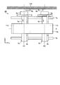
- FIG. 8 is a perspective view showing the configuration of the optical unit according to Embodiment 2 of the present invention.
- FIG. 9 is a plan view in the direction of arrow B in FIG.
- the optical unit 21 shown in these drawings is provided in the imaging apparatus and forms at least a part of an optical system that collects light from a subject and forms an image on the light receiving surface of the imaging element. 8 and 9, the same components as those of the optical unit described in the first embodiment are denoted by the same reference numerals as those in FIGS.
- the optical unit 21 includes a portion movable with respect to the main body 100 of the imaging apparatus and a portion fixed to the main body 100. First, the movable part 22 that forms a movable part of the optical unit 21 relative to the main body 100 will be described.
- the movable part 22 is provided in the holding part 24 that holds the lens 23 and the holding part 24, wound in a rectangular shape with the optical axis O ′ of the lens 23 as a central axis, and arranged along the optical axis direction.
- Two coils 25 a and 25 b and a position detection magnet (second magnet) 26 provided on the side of the holding unit 24 are included.
- Shafts 7 a and 7 b that extend parallel to the optical axis of the lens 23 and are fixed to the main body 100 pass through the holding portion 24. For this reason, the moving direction of the holding part 24 is regulated in a direction parallel to the optical axis direction of the lens 23 by the shafts 7a and 7b.
- the coils 25a and 25b intersect with the yokes 13a and 13b, respectively.
- the direction of the current flowing through the coil 25a is opposite to the direction of the current flowing through the coil 25b.
- the holding unit 24 holds one lens 23 here, the holding unit 24 may hold a lens group including a plurality of lenses whose optical axes coincide with each other.
- a magnetic sensor 27 that detects a magnetic field generated by the position detection magnet 26 is fixed to the main body 100 in the vicinity of the position detection magnet 26 provided in the movable portion 22.
- the magnetic sensor 27 is disposed at a position where the magnetic fields generated by the currents flowing through the two coils 25a and 25b cancel each other.
- the magnetic sensor 27 includes a plane P3 passing through the center of the coil 25a and orthogonal to the center axis O ′ of the coil 25a, and a plane passing through the center of the coil 25b and the center axis of the coil 25b.
- the positional relationship shown in FIG. 9 is merely an example.
- the magnetic sensor 27 may be disposed at a position where the state shown in FIG. 9 can be taken within a range in which the holding unit 24 can move.
- the coil 25a, the coil 25b, the magnets 11a, 11b, 12a, 12b, and the yokes 13a, 13b constitute one voice coil motor.
- a current is passed through the coils 25a and 25b, the current flowing through the coils 25a and 25b receives a force in the optical axis direction of the lens 23 due to the influence of the magnetic field generated by the magnets 11a, 11b, 12a and 12b.
- the movable portion 22 moves along the optical axis direction of the lens 23.
- the magnetic sensor 27 takes a state in which the directions of the magnetic fields generated by the currents flowing through the two coils 25a and 25b cancel each other within a range in which the holding unit 24 can move. Therefore, at least in the possible state, the magnetic field generated by the current flowing through the coils 25a and 25b becomes noise and the influence on the magnetic sensor 27 can be reduced. Therefore, even when a plurality of coils are used, the position of the movable part can be detected with high accuracy.
- the configuration is further simplified, which is suitable for downsizing.
- FIG. 10 is a plan view showing the configuration of the main part of the optical unit according to the modified example 2-1 of the second embodiment, as seen from the same direction as the plan view shown in FIG.
- the optical unit 21A shown in FIG. 10 currents in the same direction are passed through the coils 25a and 25b. Accordingly, in the present modification 2-1, the installation position of the magnetic sensor 27 is different from that of the second embodiment.
- the magnetic sensor 27 is disposed at a position where the magnetic fields generated by the currents flowing through the two coils 25a and 25b cancel each other. In the case shown in FIG. 10, the magnetic sensor 27 is located in a region sandwiched between the planes P3 and P4.
- FIG. 11 is a plan view showing the configuration of the main part of the optical unit according to the modified example 2-2 of the second embodiment, viewed from the same direction as the plan view shown in FIG.
- the magnetic sensor 27 is provided in the holding part 24, and the position detection magnet 26 is provided in the main body 100.
- the magnetic sensor 27 is disposed at a position where the magnetic fields generated by the currents flowing through the two coils 25a and 25b cancel each other.
- the current flowing through the coil 25a and the current flowing through the coil 25b are opposite to each other. For this reason, the magnetic sensor 27 is located outside the region sandwiched between the plane P3 and the plane P4.
- FIG. 12 is a plan view showing the configuration of the main part of the optical unit according to the modified example 2-3 of the second embodiment, as seen from the same direction as the plan view shown in FIG.
- the magnetic sensor 27 is provided in the holding part 24, and the position detection magnet 26 is provided in the main body 100.
- the magnetic sensor 27 is disposed at a position where the magnetic fields generated by the currents flowing through the two coils 25a and 25b cancel each other.
- the current flowing through the coil 25a and the current flowing through the coil 25b are in the same direction. For this reason, the magnetic sensor 27 is located in a region sandwiched between the plane P3 and the plane P4.
- FIG. 13 is a plan view showing the configuration of the main part of the optical unit according to Embodiment 3 of the present invention.
- the optical unit 31 shown in FIG. 13 includes three movable parts 32a, 32b, and 32c that are movable with respect to the main body 100 of the imaging device, a magnetic sensor 33 that is attached to the main body 100, shafts 7a and 7b, and a magnet (first 1 magnets) 34a and 34b (not shown) and yokes 13a and 13b (not shown).
- the movable portion 32a includes a holding portion 35a that holds the lens, and a coil 36a that is wound in a rectangular shape with the optical axis of the lens held by the holding portion 35a as a central axis and is provided on the holding portion 35a.
- the movable part 32b has a holding part 35b and a coil 36b.
- the movable part 32c has a holding part 35c and a coil 36c, and has a position detection magnet (second magnet) 37 provided on the side of the holding part 35c.
- the optical axes O ′′ of the lenses held by the holding portions 35a, 35b, and 35c coincide with each other.
- the shafts 7a and 7b penetrate the movable parts 32a, 32b and 32c, respectively.
- the moving directions of the holding portions 35a, 35b and 35c are regulated by the shafts 7a and 7b in a direction parallel to the optical axis direction of the lens held by each holding portion.
- the direction of the current flowing through the coil 36a is opposite to the direction of the current flowing through the coils 36b and 36c.
- the magnetic sensor 33 is disposed in the vicinity of the position detection magnet 37 so that the magnetic fields generated by the currents flowing through the two coils 36a and 36b cancel each other.
- the magnetic sensor 33 includes a plane P5 passing through the center of the coil 36a and orthogonal to the central axis O ′′ of the coil 36a, and a plane passing through the center of the coil 36b and the center of the coil 36b. It is provided outside the region sandwiched between the plane P6 orthogonal to the axis O ′′.
- the coils 36a, 36b, and 36c are respectively fixed to the movable portions 32a, 32b, and 32c, and therefore the positional relationship shown in FIG. 13 is merely an example.
- the magnetic sensor 33 should just be arrange
- the yoke 13a is provided with one magnet 34a extending along the moving direction of the movable parts 32a, 32b, 32c.
- the yoke 13b is disposed on the back side of the yoke 13a as in the first embodiment.
- the yoke 13b is provided with a magnet 34b having the same shape as the magnet 34a.
- the coil 36a constitutes a voice coil motor together with the magnets 34a and 34b and the yokes 13a and 13b.
- the coils 36b and 36c constitute a voice coil motor together with the magnets 34a and 34b and the yokes 13a and 13b.
- FIG. 13 illustrates a configuration in which one magnet 34a is surrounded by the yoke 13a, the number of magnets is not limited to this.
- the magnetic sensor 33 is in a state where the directions of the magnetic fields generated by the currents flowing through the two coils 36a and 36b cancel each other within a range in which the holding portions 35a and 35b can move. Therefore, the magnetic field generated by the current flowing through the coils 36a and 36b becomes noise and the influence on the magnetic sensor 33 can be reduced at least in the possible state. Therefore, even when a plurality of coils are used, the position of the movable part can be detected with high accuracy.
- the magnetic sensor 33 may be disposed at a position where at least two of the three coils 36a, 36b, and 36c can cancel each other.
- the magnetic sensor 33 may be provided outside the region sandwiched between the two.
- two planes that have the same direction of current flowing through at least two of the three coils 36a, 36b, and 36c pass through the centers of the two coils, and are orthogonal to the central axes of the two coils, respectively.
- the magnetic sensor 33 may be provided in a region sandwiched between the two.
- the magnetic sensor may be arranged at a position where at least two magnetic fields of the plurality of coils can cancel each other. For example, a region in which the directions of currents flowing through at least two coils out of a plurality of coils are reversed, passing through the centers of the two coils, and sandwiched between two planes orthogonal to the central axes of the two coils, respectively.
- a magnetic sensor may be provided outside.
- a magnetic sensor may be provided inside.
- FIG. 14 is a plan view showing the configuration of the main part of the optical unit according to Embodiment 4 of the present invention.
- the optical unit 41 shown in FIG. 14 includes a movable part 42 that is movable with respect to the main body 100 of the imaging device, a magnetic sensor 43 that is attached to the main body 100, shafts 7a and 7b, a magnet (first magnet) 44a, 44b and yokes 45a and 45b.
- the movable part 42 is wound in a rectangular shape in a plane perpendicular to the optical axis of the lens 46, a holding part 47 that holds the lens 46, and coils 48 a and 48 b provided in the holding part 47, and holding And a position detection magnet (second magnet) 49 provided on the side portion of the portion 47.
- Shafts 7a and 7b penetrate through movable portion 42, respectively.
- the moving direction of the holding portion 47 is regulated by the shafts 7a and 7b in a direction parallel to the optical axis direction of the lens held by each holding portion (direction perpendicular to the paper surface of FIG. 14).
- the direction of the current flowing through the coil 48a is opposite to the direction of the current flowing through the coil 48b as shown by the arrow in FIG.
- the magnetic sensor 43 is disposed at a position where magnetic fields generated by currents flowing through the two coils 48a and 48b cancel each other. As shown in FIG. 14, when the two coils 48a and 48b are arranged side by side in a plane orthogonal to the optical axis of the lens 46, the direction of the current flowing through the two coils 48a and 48b is reversed, so that the magnetic sensor 43 Regardless of the position of the magnetic field, the direction of the magnetic field is reversed.
- Magnets 44a and 44b, yokes 45a and 45b, and coils 48a and 48b constitute a voice coil motor.
- the current flowing through the coil 48a receives a force in the optical axis direction of the lens 46 due to the influence of the magnetic field generated by the magnet 44a.
- the current flowing through the coil 48b receives a force in the optical axis direction of the lens 46 due to the influence of the magnetic field generated by the magnet 44b.
- the direction of the force received by each of the currents flowing through the coils 48a and 48b is the same.
- the movable part 42 moves along the optical axis direction of the lens 46.
- the magnetic sensor 43 takes a state in which the directions of the magnetic fields generated by the currents flowing through the two coils 48a and 48b cancel each other within a range in which the holding portion 47 can move. Therefore, at least in a possible state, the magnetic field generated by the current flowing through the coils 48a and 48b becomes noise and the influence on the magnetic sensor 43 can be reduced. Therefore, even when a plurality of coils are used, the position of the movable part can be detected with high accuracy.
- the magnetic sensor 43 may be disposed at a position where at least two magnetic fields of the plurality of coils can cancel each other.
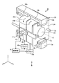
- FIG. 15 is a diagram illustrating a configuration of an endoscope system including the endoscope according to the fifth embodiment of the present invention.
- An endoscope system 200 shown in the figure includes an endoscope 90, a control device 94, and a display device 96.
- the endoscope 90 includes any of the optical units according to Embodiments 1 to 4 described above.
- the endoscope 90 can be introduced into a subject such as a human body, and optically images a predetermined observation site in the subject.
- the subject into which the endoscope 90 is introduced is not limited to a human body, but may be another living body or an artificial object such as a machine or a building.
- the endoscope 90 may be a medical endoscope or an industrial endoscope.
- the endoscope 90 includes an insertion portion 91 introduced into the subject, an operation portion 92 positioned at the proximal end of the insertion portion 91, and a universal cord 93 as a composite cable extending from the operation portion 92. Prepare.
- the insertion portion 91 is disposed at the distal end portion 91a disposed at the distal end, the bendable bending portion 91b disposed at the proximal end side of the distal end portion 91a, and the operation portion 92 disposed at the proximal end side of the bending portion 91b. And a flexible tube portion 91c having flexibility.
- the distal end portion 91a is provided with an imaging unit 80 that collects light from the subject and images the subject.
- the image capturing unit 80 is an image capturing apparatus that includes an optical unit that condenses light from a subject and an image sensor that photoelectrically converts the light collected by the optical unit and outputs it.
- the imaging device is configured using a CCD (Charge Coupled Device) or a CMOS (Complementary Metal Oxide Semiconductor).
- the endoscope 90 may be a rigid endoscope in which the insertion portion 91 does not have the flexible tube portion 91c.
- the operation unit 92 includes an angle operation unit 92a that operates the bending state of the bending unit 91b, and a zoom operation unit 92b that instructs the operation of the voice coil motor and performs a zoom operation in any of the optical units.
- the angle operation unit 92a is formed in a knob shape and the zoom operation unit 92b is formed in a lever shape, other types such as a volume switch and a push switch may be used.
- the universal cord 93 is a member that connects the operation unit 92 and the control device 94.
- the endoscope 90 is connected to the control device 94 via a connector 93 a provided at the base end portion of the universal cord 93.
- a cable 95 such as a wire, an electric wire, or an optical fiber is inserted through the insertion portion 91, the operation portion 92, and the universal cord 93.
- the control device 94 includes a drive control unit 94a that controls the bending state of the bending unit 91b, an image control unit 94b that controls the imaging unit 80, and a light source control unit 94c that controls a light source device (not shown).
- the control device 94 has a CPU and the like, and controls the entire endoscope system 200 in an integrated manner.
- the drive control unit 94a has an actuator and is mechanically connected to the operation unit 92 and the bending unit 91b via a wire.
- the drive controller 94a controls the bending state of the bending portion 91b by moving the wire forward and backward.
- the image control unit 94b is electrically connected to the imaging unit 80 and the operation unit 92 via electric lines.
- the image control unit 94b performs drive control of a voice coil motor included in the imaging unit 80 and processing of an image captured by the imaging unit 80.
- the image processed by the image control unit 94b is displayed on the display device 96.
- the light source control unit 94c is optically connected to the light source and operation unit 92 through an optical fiber.
- the light source controller 94c controls the brightness and the like of the light source emitted from the distal end portion 91a.
- the operation unit 92 may be formed separately from the insertion unit 91 and the insertion unit 91 may be operated by remote operation.
- the endoscope system 200 having the above configuration includes the imaging unit 80 including any one of the optical units described above, it can be zoomed and focused quickly and is suitable for moving image imaging.
- a driving magnet may be provided on the movable part, while a coil may be provided on the main body of the imaging apparatus.
- the cable connected to the coil does not move together with the movable part, it is particularly suitable for an endoscope in which the optical unit needs to be disposed in a limited space.
- a cylindrical frame member that guides the movable part by accommodating the movable part may be applied.
- the coils described in the first to fifth embodiments and the modifications thereof are not limited to a rectangular shape, but may be wound so as to have a shape such as an oval shape.
- the coils described in the first to third embodiments and the modifications thereof are not limited to those wound in a rectangular shape with the optical axis of the lens as the central axis, and the optical axis of the lens and the coil Similar effects can be obtained even if the central axes do not exactly match.
- a digital camera or a digital video camera may be applied as an imaging device other than the endoscope described above.
- the present invention can include various embodiments and the like not described herein, and appropriate design changes and the like can be made without departing from the technical idea described in the claims. Is possible.
Abstract
複数のコイルを用いる場合であっても可動部分の位置検出を高精度に行う。この目的のため、光学ユニットは、レンズ群を保持し、所定の固定部に対して該レンズ群の光軸方向に沿って移動可能な保持部と、光軸と交差する方向に磁気分極され、固定部および保持部のいずれか一方に設けられる第1の磁石と、固定部および保持部のうち第1の磁石が設けられていない方に設けられ、電流を流した場合に第1の磁石が作る磁界によって該電流が光軸方向の力を受ける複数のコイルと、固定部および保持部のいずれか一方に設けられる第2の磁石と、固定部および保持部のうち第2の磁石が設けられていない方に設けられ、保持部が移動可能な範囲内で複数のコイルのうち少なくとも2つの磁界の向きが打ち消し合う状態を取り得る位置に配置され、第2の磁石が作る磁界を検出する磁気センサと、を備えたことを特徴とする。
Description
本発明は、ボイスコイルモータを用いてレンズ群を駆動する光学ユニット、撮像装置および内視鏡に関する。
従来、デジタルカメラ等の撮像装置では、ズームレンズやフォーカスレンズ等の移動レンズ群を駆動するアクチュエータとしてボイスコイルモータを用いる技術が知られている(例えば、特許文献1を参照)。この技術では、移動レンズ群の位置を正確に検出するために磁気センサが設けられる。
ボイスコイルモータを用いて移動レンズ群を駆動する技術として、複数のコイルを用いて構成されるボイスコイルモータも知られている(例えば、特許文献2を参照)。
特許文献2に記載された技術に対して特許文献1に記載された位置検出用の磁気センサを設ける場合、磁気センサの設置位置によっては、各コイルを流れる電流によって発生する磁界が磁気センサを通過することに起因して、移動レンズ群を含む可動部分の位置検出に大きな誤差が生じてしまうおそれがあった。
本発明は、上記に鑑みてなされたものであって、複数のコイルを用いる場合であっても可動部分の位置検出を高精度に行うことができる光学ユニット、撮像装置および内視鏡を提供することを目的とする。
上述した課題を解決し、目的を達成するために、本発明に係る光学ユニットは、レンズ群を保持し、所定の固定部に対して該レンズ群の光軸方向に沿って移動可能な保持部と、前記光軸と交差する方向に磁気分極され、前記固定部および前記保持部のいずれか一方に設けられる第1の磁石と、前記固定部および前記保持部のうち前記第1の磁石が設けられていない方に設けられ、電流を流した場合に前記第1の磁石が作る磁界によって該電流が前記光軸方向の力を受ける複数のコイルと、前記固定部および前記保持部のいずれか一方に設けられる第2の磁石と、前記固定部および前記保持部のうち前記第2の磁石が設けられていない方に設けられ、前記保持部が移動可能な範囲内で前記複数のコイルのうち少なくとも2つの磁界の向きが打ち消し合う状態を取り得る位置に配置され、前記第2の磁石が作る磁界を検出する磁気センサと、を備えたことを特徴とする。
本発明に係る撮像装置は、上記の光学ユニットと、前記光学ユニットが集光した光を受光して電気信号に変換する撮像素子と、を備えたことを特徴とする。
本発明に係る内視鏡は、被検体の内部に挿入されて該被検体の内部を観察する内視鏡であって、上記の撮像装置と、前記被検体の内部に挿入される挿入部とを備えたことを特徴とする。
本発明によれば、複数のコイルを用いる場合であっても可動部分の位置検出を高精度に行うことができる。
以下、添付図面を参照して、本発明を実施するための形態(以下、「実施の形態」という)を説明する。
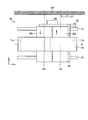
図1は、本発明の実施の形態1に係る光学ユニットの構成を示す斜視図である。図2は、図1の矢視A方向の平面図である。これらの図に示す光学ユニット1は、撮像装置に設けられ、被写体からの光を集光して撮像素子の受光面に結像させる光学系の少なくとも一部をなす。
光学ユニット1は、所定の固定部である撮像装置の本体100に対して移動可能な部分と、本体100に固定される部分とからなる。まず、光学ユニット1のうち本体100に対して移動可能な部分をなす2つの可動部2aおよび2bについて説明する。
可動部2aは、レンズ3aと、レンズ3aを保持する保持部4aと、保持部4aに設けられ、レンズ3aの光軸Oを中心軸として矩形状に巻回されたコイル5aと、保持部4aの側部に設けられた位置検出用磁石(第2の磁石)6aとを有する。保持部4aには、レンズ3aの光軸と平行に延びて本体100に固定されるシャフト7a、7bが貫通している。このため、保持部4aの移動方向は、シャフト7a、7bによってレンズ3aの光軸方向と平行な方向に規制されている。なお、ここでは保持部4aが1枚のレンズ3aを保持するものとしているが、保持部4aは互いの光軸が一致する複数枚のレンズからなるレンズ群を保持してもよい。また、シャフト7a、7bは中間部のみを記載している。シャフト7a、7bの記載方法は、以下で参照する図面においても同様である。
可動部2bは、レンズ3b、保持部4b、コイル5bおよび位置検出用磁石(第2の磁石)6bを有する。レンズ3bの光軸はレンズ3aの光軸Oと一致している。保持部4bにはシャフト7a、7bが貫通している。保持部4bの移動方向は、シャフト7a、7bによってレンズ3bの光軸方向と平行な方向に規制されている。なお、保持部4bも、複数枚のレンズからなるレンズ群を保持してもよい。
本実施の形態1では、図1および図2の矢印に示すように、コイル5aを流れる電流の向きとコイル5bを流れる電流の向きは逆である。
次に、光学ユニット1のうち本体100に固定される部分の構成を説明する。可動部2a、2bにそれぞれ設けられる位置検出用磁石6a、6bの近傍には、磁気センサ8a、8bが本体100に固定されている。磁気センサ8a、8bは、例えばホール素子や磁気抵抗効果素子(MR素子)を用いて実現され、位置検出用磁石6a、6bが作る磁界をそれぞれ検出する。
図3は、磁気センサ8a、8bの設置位置を模式的に説明するための図であり、コイル5a、5bの中心軸を通過する平面で見た模式図である。上述したように、2つのコイル5a、5bを流れる電流は逆向きである。このため、図3に示す平面で見たとき、コイル5aを流れる電流が発生する磁界はコイル5aに対して反時計回りであるのに対し、コイル5bを流れる電流が発生する磁界はコイル5bに対して時計回りである。
磁気センサ8a、8bは、光軸に沿って配置された2つのコイル5a、5bを流れる電流がそれぞれ作る磁界が互いに打ち消し合うような位置に配置される。図3に示す場合、磁気センサ8aは、コイル5aの中心を通る平面であってコイル5aの中心軸Oと直交する平面P1よりもコイル5bから遠い領域に設けられる。また、磁気センサ8bは、コイル5bの中心を通る平面であってコイル5bの中心軸Oと直交する平面P2よりもコイル5aから遠い領域に設けられる。換言すると、磁気センサ8a、8bは、平面P1と平面P2で挟まれる領域外に位置する。これにより、コイル5a、5bを流れる電流がそれぞれ作る磁界によって磁気センサ8a、8bが受ける影響を抑制することができるとともに、可動部2a、2bの的確な駆動制御を実現することができる。
なお、コイル5a、5bは、それぞれ可動部2a、2bに固定されるため、図3に示す位置関係はあくまでも一例に過ぎない。磁気センサ8a、8bは、保持部4a、4bがそれぞれ移動可能な範囲内において、図3に示す状態を取り得る位置に配置されていればよい。したがって、例えば磁気センサ8a、8bの一方のみが、図3に示す状態を取るような場合も起こりうる。
磁気センサ8a、8bの検出結果は制御部9に送られる。制御部9は、磁気センサ8a、8bの検出結果をもとに可動部2a、2bの位置を算出する。制御部9は、可動部2a、2bの位置に応じてドライバ10a、10bの駆動を制御することにより、ドライバ10aからコイル5aに流す電流およびドライバ10bからコイル5bに流す電流をそれぞれ決定する。制御部9は、CPU(Central Processing Unit)等を用いて構成され、光学ユニット1の動作を統括して制御する。制御部9、ドライバ10a、10bは本体100に固定される。
コイル5aのなす矩形の4辺のうち対向する2辺の外周側には磁石(第1の磁石)11a、12aがそれぞれ設けられる。また、コイル5bの矩形の対向する2辺の外周側には磁石(第1の磁石)11b、12bがそれぞれ設けられる。磁石11a、11bは、コイル5a、5bとそれぞれ交差して周回するヨーク13aの内周面側に配置される。磁石12a、12bは、コイル5a、5bとそれぞれ交差して周回し、ヨーク13aと対向するヨーク13bの内周面側に配置される。ヨーク13aは、鉄または鋼を用いて構成され、磁石11a、11bとともに磁気回路を形成する。ヨーク13bは、ヨーク13aと同じ材料を用いて構成され、磁石12a、12bとともに磁気回路を形成する。ヨーク13a、13bは、本体100に固定される。磁石11a、11b、12a、12bは、コイル5a、5bの中心軸方向、換言すればレンズ3a、3bの光軸方向と直交する方向に磁気分極している。なお、より一般には、磁石11a、11b、12a、12bは、コイル5a、5bの中心軸方向(レンズ3a、3bの光軸方向)と交差する方向に磁気分極していればよい。
コイル5a、磁石11a、12a、ヨーク13aおよび13bはボイスコイルモータを構成する。同様に、コイル5b、磁石11b、12b、ヨーク13aおよび13bもボイスコイルモータを構成する。コイル5aに電流を流すと、磁石11a、12aが作る磁界の影響によってコイル5aを流れる電流がレンズ3aの光軸方向の力を受ける。その結果、可動部2aがレンズ3aの光軸方向に沿って移動する。コイル5bに電流を流した場合も、コイル5aに電流を流した場合と同様にして可動部2bがレンズ3bの光軸方向に沿って移動する。
なお、本実施の形態1において、ヨーク13a、13bを用いることなくボイスコイルモータを構成することも可能である。また、磁石11aと磁石11b、および磁石12aと磁石12bをそれぞれ一体としてもよい。これらの点は、後述する全ての実施の形態において共通する事項である。
また、本実施の形態1において、光学ユニット1は磁気センサおよび位置検出用磁石の組を少なくとも一組備えていればよい。すなわち、磁気センサ8a、8bの一方は他の検出手段に置き換えることも可能である。この場合には、置き換えた方の磁気センサに対応して設けられる位置検出用磁石も不要となる。磁気センサと位置検出用磁石を用いることによって高精度の位置検出を行うことができるため、可動部2a、2bのうち、より精度が要求される可動部に対して磁気センサと位置検出用磁石の組を設けることが好ましい。
以上説明した本発明の実施の形態1によれば、磁気センサ8a、8bは、保持部4a、4bが移動可能な範囲内で2つのコイル5a、5bを流れる電流がそれぞれ作る磁界の向きが打ち消し合う状態を取り得る位置に存在するため、少なくともその取り得る状態ではコイル5a、5bを流れる電流によって発生する磁界がノイズとなって磁気センサ8a、8bに及ぼす影響を低減することができる。したがって、複数のコイルを用いる場合であっても可動部分の位置検出を高精度に行うことができる。
(変形例1-1)
図4は、実施の形態1の変形例1-1に係る光学ユニットの要部の構成を示す平面図であり、図2に示す平面図と同様の方向から見た図である。図4に示す光学ユニット1Aでは、コイル5aとコイル5bに同じ向きの電流を流す。これに伴って本変形例1-1では、磁気センサ8a、8bの設置位置が実施の形態1と異なる。
図4は、実施の形態1の変形例1-1に係る光学ユニットの要部の構成を示す平面図であり、図2に示す平面図と同様の方向から見た図である。図4に示す光学ユニット1Aでは、コイル5aとコイル5bに同じ向きの電流を流す。これに伴って本変形例1-1では、磁気センサ8a、8bの設置位置が実施の形態1と異なる。
図5は、磁気センサ8a、8bの設置位置を説明するための図であり、コイル5a、5bの中心軸を通過する平面で見た模式図である。2つのコイル5a、5bをそれぞれ流れる電流は同じ向きである。このため、図5に示す平面で見たとき、コイル5aを流れる電流が作る磁界はコイル5aに対して反時計回りであり、コイル5bを流れる電流が作る磁界もコイル5bに対して反時計回りである。
本変形例1-1でも、磁気センサ8a、8bは、2つのコイル5a、5bを流れる電流がそれぞれ作る磁界が互いに打ち消し合うような位置に配置される。図5に示す場合、磁気センサ8aは、平面P1よりもコイル5bに近い領域に設けられる。また、磁気センサ8bは、平面P2よりもコイル5aに近い領域に設けられる。換言すると、磁気センサ8a、8bは、平面P1と平面P2で挟まれる領域内に位置する。
なお、本変形例1-1においても、コイル5a、5bは、それぞれ可動部2a、2bに固定されるため、図5に示す位置関係はあくまでも一例に過ぎない。磁気センサ8a、8bは、保持部4a、4bがそれぞれ移動可能な範囲内において、図5に示す状態を取り得る位置に配置されていればよい。したがって、例えば磁気センサ8a、8bの一方のみが図4に示す状態を取るような場合も起こりうる。
(変形例1-2)
図6は、実施の形態1の変形例1-2に係る光学ユニットの要部の構成を示す平面図であり、図2に示す平面図と同様の方向から見た図である。図6に示す光学ユニット1Bでは、可動部2Ba、2Bbにおいて、磁気センサ8a、8bを保持部4a、4bにそれぞれ設ける一方、位置検出用磁石6a、6bを本体100に設けている。磁気センサ8a、8bは、2つのコイル5a、5bを流れる電流がそれぞれ作る磁界が互いに打ち消し合うような位置に配置される。
図6は、実施の形態1の変形例1-2に係る光学ユニットの要部の構成を示す平面図であり、図2に示す平面図と同様の方向から見た図である。図6に示す光学ユニット1Bでは、可動部2Ba、2Bbにおいて、磁気センサ8a、8bを保持部4a、4bにそれぞれ設ける一方、位置検出用磁石6a、6bを本体100に設けている。磁気センサ8a、8bは、2つのコイル5a、5bを流れる電流がそれぞれ作る磁界が互いに打ち消し合うような位置に配置される。
本変形例1-2では、コイル5a、5bにそれぞれ流れる電流は逆向きである。このため、磁気センサ8aは、平面P1よりもコイル5bから遠い領域に設けられる。また、磁気センサ8bは、平面P2よりもコイル5aから遠い領域に設けられる。換言すると、磁気センサ8a、8bは、平面P1と平面P2で挟まれる領域外に位置する。
(変形例1-3)
図7は、実施の形態1の変形例1-3に係る光学ユニットの要部の構成を示す平面図であり、図2に示す平面図と同様の方向から見た図である。図7に示す光学ユニット1Cでは、可動部2Ca、2Cbにおいて、磁気センサ8a、8bを保持部4a、4bにそれぞれ設ける一方、位置検出用磁石6a、6bを本体100に設けている。磁気センサ8a、8bは、2つのコイル5a、5bを流れる電流がそれぞれ作る磁界が互いに打ち消し合うような位置に配置される。
図7は、実施の形態1の変形例1-3に係る光学ユニットの要部の構成を示す平面図であり、図2に示す平面図と同様の方向から見た図である。図7に示す光学ユニット1Cでは、可動部2Ca、2Cbにおいて、磁気センサ8a、8bを保持部4a、4bにそれぞれ設ける一方、位置検出用磁石6a、6bを本体100に設けている。磁気センサ8a、8bは、2つのコイル5a、5bを流れる電流がそれぞれ作る磁界が互いに打ち消し合うような位置に配置される。
本変形例1-3では、コイル5a、5bにそれぞれ流れる電流は同じ向きである。このため、磁気センサ8aは、平面P1よりもコイル5bに近い領域に設けられる。また、磁気センサ8bは、平面P2よりもコイル5aに近い領域に設けられる。換言すると、磁気センサ8a、8bは、平面P1と平面P2で挟まれる領域内に位置する。
以上説明した変形例1-1~1-3が、実施の形態1と同様の効果を奏することは言うまでもない。
(実施の形態2)
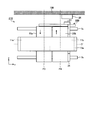
図8は、本発明の実施の形態2に係る光学ユニットの構成を示す斜視図である。図9は、図8の矢視B方向の平面図である。これらの図に示す光学ユニット21は、撮像装置に設けられ、被写体からの光を集光して撮像素子の受光面に結像させる光学系の少なくとも一部をなす。図8および図9において、実施の形態1で説明した光学ユニットと同じ構成要素には、図1および図2等と同じ符号を付してある。
図8は、本発明の実施の形態2に係る光学ユニットの構成を示す斜視図である。図9は、図8の矢視B方向の平面図である。これらの図に示す光学ユニット21は、撮像装置に設けられ、被写体からの光を集光して撮像素子の受光面に結像させる光学系の少なくとも一部をなす。図8および図9において、実施の形態1で説明した光学ユニットと同じ構成要素には、図1および図2等と同じ符号を付してある。
光学ユニット21は、撮像装置の本体100に対して移動可能な部分と、本体100に固定される部分とからなる。まず、光学ユニット21のうち本体100に対して移動可能な部分をなす可動部22について説明する。
可動部22は、レンズ23を保持する保持部24と、保持部24に設けられ、レンズ23の光軸O’を中心軸としてそれぞれ矩形状に巻回され、光軸方向に沿って並べられた2つのコイル25a、25bと、保持部24の側部に設けられた位置検出用磁石(第2の磁石)26とを有する。保持部24には、レンズ23の光軸と平行に延びて本体100に固定されるシャフト7a、7bが貫通している。このため、保持部24の移動方向は、シャフト7a、7bによってレンズ23の光軸方向と平行な方向に規制されている。コイル25a、25bは、ヨーク13a、13bとそれぞれ交差する。本実施の形態2では、図8および図9の矢印に示すように、コイル25aを流れる電流の向きとコイル25bを流れる電流の向きは逆である。なお、ここでは保持部24が1枚のレンズ23を保持するものとしているが、保持部24は互いの光軸が一致する複数枚のレンズからなるレンズ群を保持してもよい。
次に、光学ユニット21のうち本体100に固定される部分の構成を説明する。可動部22に設けられる位置検出用磁石26の近傍には、位置検出用磁石26が作る磁界を検出する磁気センサ27が本体100に固定される。磁気センサ27は、2つのコイル25a、25bを流れる電流がそれぞれ作る磁界が互いに打ち消し合うような位置に配置される。図9に示す場合、磁気センサ27は、コイル25aの中心を通る平面であってコイル25aの中心軸O’と直交する平面P3と、コイル25bの中心を通る平面であってコイル25bの中心軸O’と直交する平面P4とに挟まれる領域外に設けられる。これにより、コイル25a、25bを流れる電流がそれぞれ作る磁界によって磁気センサ27が影響を受けることを抑制できるとともに、可動部22の的確な駆動制御を実現することができる。
なお、コイル25a、25bは、可動部22に固定されるため、図9に示す位置関係はあくまでも一例に過ぎない。磁気センサ27は、保持部24が移動可能な範囲内において、図9に示す状態を取り得る位置に配置されていればよい。
コイル25a、コイル25b、磁石11a、11b、12a、12b、ヨーク13a、13bは1つのボイスコイルモータを構成する。コイル25a、25bに電流を流すと、磁石11a、11b、12a、12bが作る磁界の影響によってコイル25a、25bを流れる電流がレンズ23の光軸方向の力を受ける。その結果、可動部22がレンズ23の光軸方向に沿って移動する。
以上説明した本発明の実施の形態2によれば、磁気センサ27は、保持部24が移動可能な範囲内で2つのコイル25a、25bを流れる電流がそれぞれ作る磁界の向きが打ち消し合う状態を取り得る位置に存在するため、少なくともその取り得る状態ではコイル25a、25bを流れる電流によって発生する磁界がノイズとなって磁気センサ27に及ぼす影響を低減することができる。したがって、複数のコイルを用いる場合であっても可動部分の位置検出を高精度に行うことができる。
また、本実施の形態2によれば、コイル25a、25bは1つの保持部24に固定されるため、構成が一段と簡易であり、小型化に好適である。
(変形例2-1)
図10は、実施の形態2の変形例2-1に係る光学ユニットの要部の構成を示す平面図であり、図9に示す平面図と同様の方向から見た図である。図10に示す光学ユニット21Aでは、コイル25aとコイル25bには同じ向きの電流を流す。これに伴って本変形例2-1では、磁気センサ27の設置位置が実施の形態2と異なる。
図10は、実施の形態2の変形例2-1に係る光学ユニットの要部の構成を示す平面図であり、図9に示す平面図と同様の方向から見た図である。図10に示す光学ユニット21Aでは、コイル25aとコイル25bには同じ向きの電流を流す。これに伴って本変形例2-1では、磁気センサ27の設置位置が実施の形態2と異なる。
本変形例2-1でも、磁気センサ27は、2つのコイル25a、25bを流れる電流がそれぞれ作る磁界が互いに打ち消し合うような位置に配置される。図10に示す場合、磁気センサ27は、平面P3と平面P4に挟まれる領域内に位置する。
なお、本変形例2-1においても、コイル25a、25bは、可動部22に固定されるため、図10に示す位置関係はあくまでも一例に過ぎない。磁気センサ27は、保持部24が移動可能な範囲内において、図10に示す状態を取り得る位置に配置されていればよい。
(変形例2-2)
図11は、実施の形態2の変形例2-2に係る光学ユニットの要部の構成を示す平面図であり、図9に示す平面図と同様の方向から見た図である。図11に示す光学ユニット21Bでは、可動部22Bにおいて、磁気センサ27を保持部24に設ける一方、位置検出用磁石26を本体100に設けている。磁気センサ27は、2つのコイル25a、25bを流れる電流がそれぞれ作る磁界が互いに打ち消し合うような位置に配置される。本変形例2-2では、コイル25aに流れる電流とコイル25bに流れる電流は逆向きである。このため、磁気センサ27は、平面P3と平面P4とに挟まれる領域外に位置する。
図11は、実施の形態2の変形例2-2に係る光学ユニットの要部の構成を示す平面図であり、図9に示す平面図と同様の方向から見た図である。図11に示す光学ユニット21Bでは、可動部22Bにおいて、磁気センサ27を保持部24に設ける一方、位置検出用磁石26を本体100に設けている。磁気センサ27は、2つのコイル25a、25bを流れる電流がそれぞれ作る磁界が互いに打ち消し合うような位置に配置される。本変形例2-2では、コイル25aに流れる電流とコイル25bに流れる電流は逆向きである。このため、磁気センサ27は、平面P3と平面P4とに挟まれる領域外に位置する。
(変形例2-3)
図12は、実施の形態2の変形例2-3に係る光学ユニットの要部の構成を示す平面図であり、図9に示す平面図と同様の方向から見た図である。図12に示す光学ユニット21Cでは、可動部22Cにおいて、磁気センサ27を保持部24に設ける一方、位置検出用磁石26を本体100に設けている。磁気センサ27は、2つのコイル25a、25bを流れる電流がそれぞれ作る磁界が互いに打ち消し合うような位置に配置される。本変形例2-3では、コイル25aに流れる電流とコイル25bに流れる電流は同じ向きである。このため、磁気センサ27は、平面P3と平面P4とに挟まれる領域内に位置する。
図12は、実施の形態2の変形例2-3に係る光学ユニットの要部の構成を示す平面図であり、図9に示す平面図と同様の方向から見た図である。図12に示す光学ユニット21Cでは、可動部22Cにおいて、磁気センサ27を保持部24に設ける一方、位置検出用磁石26を本体100に設けている。磁気センサ27は、2つのコイル25a、25bを流れる電流がそれぞれ作る磁界が互いに打ち消し合うような位置に配置される。本変形例2-3では、コイル25aに流れる電流とコイル25bに流れる電流は同じ向きである。このため、磁気センサ27は、平面P3と平面P4とに挟まれる領域内に位置する。
以上説明した変形例2-1~2-3が実施の形態2と同様の効果を奏することは言うまでもない。
(実施の形態3)
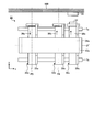
図13は、本発明の実施の形態3に係る光学ユニットの要部の構成を示す平面図である。図13において、実施の形態1で説明した光学ユニットと同じ構成要素には、図1および図2等と同じ符号を付してある。図13に示す光学ユニット31は、撮像装置の本体100に対して移動可能な3つの可動部32a、32bおよび32cと、本体100に取り付けられる磁気センサ33と、シャフト7a、7bと、磁石(第1の磁石)34a、34b(図示せず)と、ヨーク13a、13b(図示せず)と、を有する。
図13は、本発明の実施の形態3に係る光学ユニットの要部の構成を示す平面図である。図13において、実施の形態1で説明した光学ユニットと同じ構成要素には、図1および図2等と同じ符号を付してある。図13に示す光学ユニット31は、撮像装置の本体100に対して移動可能な3つの可動部32a、32bおよび32cと、本体100に取り付けられる磁気センサ33と、シャフト7a、7bと、磁石(第1の磁石)34a、34b(図示せず)と、ヨーク13a、13b(図示せず)と、を有する。
可動部32aは、レンズを保持する保持部35aと、保持部35aが保持するレンズの光軸を中心軸として矩形状に巻回され、保持部35aに設けられるコイル36aと、を有する。可動部32bは、保持部35bおよびコイル36bを有する。可動部32cは、保持部35cおよびコイル36cを有するとともに、保持部35cの側部に設けられた位置検出用磁石(第2の磁石)37を有する。保持部35a、35bおよび35cがそれぞれ保持するレンズの光軸O’’は一致している。可動部32a、32bおよび32cにはシャフト7a、7bがそれぞれ貫通している。保持部35a、35bおよび35cの移動方向は、シャフト7a、7bによって各保持部が保持するレンズの光軸方向と平行な方向に規制されている。本実施の形態3では、図13の矢印に示すように、コイル36aを流れる電流の向きは、コイル36b、36cを流れる電流の向きと逆である。
磁気センサ33は、位置検出用磁石37の近傍であって2つのコイル36a、36bを流れる電流がそれぞれ作る磁界が互いに打ち消し合うような位置に配置される。図13に示す場合、磁気センサ33は、コイル36aの中心を通る平面であってコイル36aの中心軸O’’と直交する平面P5と、コイル36bの中心を通る平面であってコイル36bの中心軸O’’と直交する平面P6とに挟まれる領域外に設けられる。
本実施の形態3において、コイル36a、36b、36cは可動部32a、32b、32cにそれぞれ固定されるため、図13に示す位置関係はあくまでも一例に過ぎない。磁気センサ33は、保持部35a、35bが移動可能な範囲内において、図13に示す状態を取り得る位置に配置されていればよい。
ヨーク13aには、可動部32a、32b、32cの移動方向に沿って延びる1つの磁石34aが設けられている。図13において、ヨーク13aの紙面奥側には、実施の形態1と同様にヨーク13bが配置されている。ヨーク13bには、磁石34aと同じ形状を有する磁石34bが設けられている。
コイル36aは、磁石34a、34b、ヨーク13a、13bとともにボイスコイルモータを構成する。同様に、コイル36bおよび36cも、それぞれが磁石34a、34b、ヨーク13a、13bとともにボイスコイルモータを構成する。
コイル36aに電流を流すと、2つの磁石34a、34bが作る磁界の影響によってコイル36aを流れる電流が光軸方向の力を受ける。その結果、可動部32aが光軸方向に沿って移動する。コイル36b、36cに電流を流した場合も、コイル36aに電流を流した場合と同様にして可動部32b、32cが光軸方向に沿ってそれぞれ移動する。
なお、図13では、1つの磁石34aをヨーク13aが取り囲んだ構成を例示しているが、磁石の個数はこれに限定されるものではない。
以上説明した本発明の実施の形態3によれば、磁気センサ33は、保持部35a、35bが移動可能な範囲内で2つのコイル36a、36bを流れる電流がそれぞれ作る磁界の向きが打ち消し合う状態を取り得る位置に存在するため、少なくともその取り得る状態ではコイル36a、36bを流れる電流によって発生する磁界がノイズとなって磁気センサ33に及ぼす影響を低減することができる。したがって、複数のコイルを用いる場合であっても可動部分の位置検出を高精度に行うことができる。
なお、3つのコイル36a、36b、36cのうち少なくとも2つの磁界の向きが打ち消し合う状態を取り得る位置に磁気センサ33を配置してもよい。例えば、3つのコイル36a、36b、36cのうち少なくとも2つのコイルを流れる電流の向きを逆とし、その2つのコイルの中心をそれぞれ通過するとともにその2つのコイルの中心軸とそれぞれ直交する2つの平面に挟まれた領域外に磁気センサ33を設けてもよい。また、3つのコイル36a、36b、36cのうち少なくとも2つのコイルを流れる電流の向きを同じとし、その2つのコイルの中心をそれぞれ通過するとともにその2つのコイルの中心軸とそれぞれ直交する2つの平面に挟まれた領域内に磁気センサ33を設けてもよい。
また、より一般に複数のコイルとして4つ以上のコイルを、互いの中心軸を平行にして並べで配置することも可能である。この場合にも、複数のコイルのうち少なくとも2つの磁界の向きが打ち消し合う状態を取り得る位置に磁気センサを配置すればよい。例えば、複数のコイルのうち少なくとも2つのコイルを流れる電流の向きを逆とし、その2つのコイルの中心をそれぞれ通過するとともにその2つのコイルの中心軸とそれぞれ直交する2つの平面に挟まれた領域外に磁気センサを設けてもよい。また、複数のコイルのうち少なくとも2つのコイルを流れる電流の向きを同じとし、その2つのコイルの中心をそれぞれ通過するとともにその2つのコイルの中心軸とそれぞれ直交する2つの平面に挟まれた領域内に磁気センサを設けてもよい。
(実施の形態4)
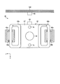
図14は、本発明の実施の形態4に係る光学ユニットの要部の構成を示す平面図である。図14において、実施の形態1で説明した光学ユニットと同じ構成要素には、図1および図2等と同じ符号を付してある。図14に示す光学ユニット41は、撮像装置の本体100に対して移動可能な可動部42と、本体100に取り付けられる磁気センサ43と、シャフト7a、7bと、磁石(第1の磁石)44a、44bと、ヨーク45a、45bと、を有する。
図14は、本発明の実施の形態4に係る光学ユニットの要部の構成を示す平面図である。図14において、実施の形態1で説明した光学ユニットと同じ構成要素には、図1および図2等と同じ符号を付してある。図14に示す光学ユニット41は、撮像装置の本体100に対して移動可能な可動部42と、本体100に取り付けられる磁気センサ43と、シャフト7a、7bと、磁石(第1の磁石)44a、44bと、ヨーク45a、45bと、を有する。
可動部42は、レンズ46と、レンズ46を保持する保持部47と、レンズ46の光軸と直交する平面内で矩形状に巻回され、保持部47に設けられるコイル48a、48bと、保持部47の側部に設けられた位置検出用磁石(第2の磁石)49と、を有する。可動部42にはシャフト7a、7bがそれぞれ貫通している。保持部47の移動方向は、シャフト7a、7bによって各保持部が保持するレンズの光軸方向と平行な方向(図14の紙面に垂直な方向)に規制されている。本実施の形態4では、図14の矢印に示すように、コイル48aを流れる電流の向きは、コイル48bを流れる電流の向きと逆である。
磁気センサ43は、2つのコイル48a、48bを流れる電流がそれぞれ作る磁界が互いに打ち消し合うような位置に配置される。図14に示すように2つのコイル48a、48bをレンズ46の光軸と直交する平面内に並べて配置する場合、2つのコイル48a、48bを流れる電流の向きを逆にすることにより、磁気センサ43の配置位置に関わらず、磁界の向きは逆となる。
磁石44a、44b、ヨーク45a、45b、コイル48a、48bはボイスコイルモータを構成する。コイル48aに電流を流すと、磁石44aが作る磁界の影響によってコイル48aを流れる電流がレンズ46の光軸方向の力を受ける。同様に、コイル48bに電流を流すと、磁石44bが作る磁界の影響によってコイル48bを流れる電流がレンズ46の光軸方向の力を受ける。コイル48a、48bをそれぞれ流れる電流が受ける力の方向は同じである。この結果、可動部42がレンズ46の光軸方向に沿って移動する。
以上説明した本発明の実施の形態4によれば、磁気センサ43は、保持部47が移動可能な範囲内で2つのコイル48a、48bを流れる電流がそれぞれ作る磁界の向きが打ち消し合う状態を取り得る位置に存在するため、少なくともその取り得る状態ではコイル48a、48bを流れる電流によって発生する磁界がノイズとなって磁気センサ43に及ぼす影響を低減することができる。したがって、複数のコイルを用いる場合であっても可動部分の位置検出を高精度に行うことができる。
なお、複数のコイルとして3つ以上のコイルをレンズ46の光軸と直交する平面内に並べて配置することも可能である。この場合にも、複数のコイルのうち少なくとも2つの磁界の向きが打ち消し合う状態を取り得る位置に磁気センサ43を配置すればよい。
(実施の形態5)
図15は、本発明の実施の形態5に係る内視鏡を備えた内視鏡システムの構成を示す図である。同図に示す内視鏡システム200は、内視鏡90と、制御装置94と、表示装置96とを備える。内視鏡90は、上述した実施の形態1~4に係る光学ユニットのいずれかを備える。
図15は、本発明の実施の形態5に係る内視鏡を備えた内視鏡システムの構成を示す図である。同図に示す内視鏡システム200は、内視鏡90と、制御装置94と、表示装置96とを備える。内視鏡90は、上述した実施の形態1~4に係る光学ユニットのいずれかを備える。
内視鏡90は、人体等の被検体内に導入可能であって、被検体内の所定の観察部位を光学的に撮像する。なお、内視鏡90が導入される被検体は、人体に限らず、他の生体でもよく、機械、建造物等の人工物でもよい。換言すれば、内視鏡90は、医療用内視鏡でもよいし、工業用内視鏡でもよい。
内視鏡90は、被検体の内部に導入される挿入部91と、挿入部91の基端に位置する操作部92と、操作部92から延出される複合ケーブルとしてのユニバーサルコード93と、を備える。
挿入部91は、先端に配設される先端部91a、先端部91aの基端側に配設される湾曲自在な湾曲部91b、および湾曲部91bの基端側に配設されて操作部92の先端側に接続され可撓性を有する可撓管部91cを有する。先端部91aには、被写体からの光を集光して該被写体を撮像する撮像部80が設けられている。撮像部80は、被写体からの光を集光する光学ユニットと、光学ユニットが集光した光を光電変換して出力する撮像素子とを有する撮像装置である。撮像素子は、CCD(Charge Coupled Device)またはCMOS(Complementary Metal Oxide Semiconductor)を用いて構成される。なお、内視鏡90は、挿入部91に可撓管部91cを有しない硬性内視鏡でもよい。
操作部92は、湾曲部91bの湾曲状態を操作するアングル操作部92aと、上述したボイスコイルモータの作動を指示し、光学ユニットのいずれかにおけるズーム作動を行うズーム操作部92bと、を有する。アングル操作部92aはノブ形状で形成され、ズーム操作部92bはレバー形状で形成されているが、それぞれボリュームスイッチ、プッシュスイッチ等の他の形式であってもよい。
ユニバーサルコード93は、操作部92と制御装置94とを接続する部材である。内視鏡90は、ユニバーサルコード93の基端部に設けられるコネクタ93aを介して制御装置94に接続される。
挿入部91、操作部92およびユニバーサルコード93には、ワイヤ、電気線および光ファイバ等のケーブル95が挿通される。
制御装置94は、湾曲部91bの湾曲状態を制御する駆動制御部94aと、撮像部80を制御する画像制御部94bと、図示しない光源装置を制御する光源制御部94cと、を有する。制御装置94は、CPU等を有し、内視鏡システム200の全体を統括して制御する。
駆動制御部94aは、アクチュエータを有し、ワイヤを介して操作部92および湾曲部91bと機械的に接続される。駆動制御部94aは、ワイヤを進退させることで湾曲部91bの湾曲状態を制御する。
画像制御部94bは、電気線を介して撮像部80および操作部92と電気的に接続される。画像制御部94bは、撮像部80が有するボイスコイルモータの駆動制御および撮像部80が撮像した画像の処理を行う。画像制御部94bが処理した画像は、表示装置96で表示される。
光源制御部94cは、光ファイバを介して光源および操作部92と光学的に接続される。光源制御部94cは、先端部91aから照射される光源の明るさ等を制御する。
なお、操作部92を挿入部91と別体で形成し、遠隔操作によって挿入部91の操作を行う構成としてもよい。
以上の構成を有する内視鏡システム200は、上述したいずれかの光学ユニットを有する撮像部80を備えるため、小型で迅速にズームやフォーカスを行うことができ、動画撮像に好適である。
(その他の実施の形態)
ここまで、本発明を実施するための形態を説明してきたが、本発明は上述した実施の形態1~5によってのみ限定されるべきものではない。例えば、可動部に駆動用の磁石を設ける一方、撮像装置の本体にコイルを設けてもよい。この場合、コイルに接続されるケーブルが可動部とともに動くことがないため、特に限られたスペースに光学ユニットを配設する必要がある内視鏡に好適である。
ここまで、本発明を実施するための形態を説明してきたが、本発明は上述した実施の形態1~5によってのみ限定されるべきものではない。例えば、可動部に駆動用の磁石を設ける一方、撮像装置の本体にコイルを設けてもよい。この場合、コイルに接続されるケーブルが可動部とともに動くことがないため、特に限られたスペースに光学ユニットを配設する必要がある内視鏡に好適である。
また、可動部を拘束してガイドする手段としてシャフトを用いる代わりに、可動部を収容することによって可動部をガイドする筒状の枠部材を適用してもよい。
また、上述した実施の形態1~5およびそれらの変形例で説明したコイルは矩形状に限らず、小判型などの形状をなすように巻回したものでもよい。また、上述した実施の形態1~3およびそれらの変形例で説明したコイルは、レンズの光軸を中心軸として矩形状に巻回したものに限られるわけではなく、レンズの光軸とコイルの中心軸が厳密に一致していなくても同様の効果を得ることができる。
また、上述した内視鏡以外の撮像装置として、デジタルカメラやデジタルビデオカメラを適用してもよい。
このように、本発明は、ここでは記載していない様々な実施の形態等を含み得るものであり、請求の範囲に記載した技術的思想を逸脱しない範囲内において適宜設計変更等を行うことが可能である。
1、1A、1B、1C、21、21A、21B、21C、31、41 光学ユニット
2a、2b、2Ba、2Bb、2Ca、2Cb、22、22A、22B、22C、32a、32b、32c、42 可動部
3a、3b、23、46 レンズ
4a、4b、24、35a、35b、35c、47 保持部
5a、5b、25a、25b、36a、36b、36c、48a、48b コイル
6a、6b、26、37、49 位置検出用磁石(第2の磁石)
7a、7b シャフト
8a、8b、27、33、43 磁気センサ
9 制御部
10a、10b ドライバ
11a、11b、12a、12b、34a、34b、44a、44b 磁石(第1の磁石)
13a、13b、45a、45b ヨーク
80 撮像部(撮像装置)
90 内視鏡
91 挿入部
91a 先端部
91b 湾曲部
91c 可撓管部
92 操作部
92a アングル操作部
92b ズーム操作部
93 ユニバーサルコード
93a コネクタ
94 制御装置
94a 駆動制御部
94b 画像制御部
94c 光源制御部
95 ケーブル
96 表示装置
100 本体(固定部)
200 内視鏡システム
Claims (13)
- レンズ群を保持し、所定の固定部に対して該レンズ群の光軸方向に沿って移動可能な保持部と、
前記光軸と交差する方向に磁気分極され、前記固定部および前記保持部のいずれか一方に設けられる第1の磁石と、
前記固定部および前記保持部のうち前記第1の磁石が設けられていない方に設けられ、電流を流した場合に前記第1の磁石が作る磁界によって該電流が前記光軸方向の力を受ける複数のコイルと、
前記固定部および前記保持部のいずれか一方に設けられる第2の磁石と、
前記固定部および前記保持部のうち前記第2の磁石が設けられていない方に設けられ、前記保持部が移動可能な範囲内で前記複数のコイルのうち少なくとも2つの磁界の向きが打ち消し合う状態を取り得る位置に配置され、前記第2の磁石が作る磁界を検出する磁気センサと、
を備えたことを特徴とする光学ユニット。 - 前記複数のコイルは、互いの中心軸を平行にして並べて配置されることを特徴とする請求項1に記載の光学ユニット。
- 前記複数のコイルは、前記光軸方向に沿って配置され、流れる電流の向きが逆である少なくとも2つのコイルを含み、
前記磁気センサは、前記2つのコイルの中心をそれぞれ通過するとともに前記2つのコイルの中心軸とそれぞれ直交する2つの平面に挟まれた領域外に位置することを特徴とする請求項1または2に記載の光学ユニット。 - 前記複数のコイルは、前記光軸方向に沿って配置され、流れる電流の向きが同じである少なくとも2つのコイルを含み、
前記磁気センサは、前記2つのコイルの中心をそれぞれ通過するとともに前記2つのコイルの中心軸とそれぞれ直交する2つの平面に挟まれた領域内に位置することを特徴とする請求項1または2に記載の光学ユニット。 - 前記複数のコイルは、前記光軸と直交する平面内に並べて配置され、流れる電流の向きが逆である少なくとも2つのコイルを含むことを特徴とする請求項1または2に記載の光学ユニット。
- 前記複数のコイルが前記保持部に固定されていることを特徴とする請求項1~5のいずれか一項に記載の光学ユニット。
- 前記複数のコイルは、1つの前記保持部に固定されていることを特徴とする請求項6に記載の光学ユニット。
- 前記複数のコイルは、複数の前記保持部のいずれかにそれぞれ固定されていることを特徴とする請求項6に記載の光学ユニット。
- 前記複数のコイルが前記固定部に固定されていることを特徴とする請求項1~5のいずれか一項に記載の光学ユニット。
- 前記磁気センサが前記保持部に固定されていることを特徴とする請求項1~5のいずれか一項に記載の光学ユニット。
- 前記磁気センサが前記固定部に固定されていることを特徴とする請求項1~5のいずれか一項に記載の光学ユニット。
- 請求項1~11のいずれか一項に記載の光学ユニットと、
前記光学ユニットが集光した光を受光して電気信号に変換する撮像素子と、
を備えたことを特徴とする撮像装置。 - 被検体の内部に挿入されて該被検体の内部を観察する内視鏡であって、
請求項12に記載の撮像装置と、前記被検体の内部に挿入される挿入部とを備えたことを特徴とする内視鏡。
Priority Applications (1)
| Application Number | Priority Date | Filing Date | Title |
|---|---|---|---|
| PCT/JP2015/065433 WO2016189736A1 (ja) | 2015-05-28 | 2015-05-28 | 光学ユニット、撮像装置および内視鏡 |
Applications Claiming Priority (1)
| Application Number | Priority Date | Filing Date | Title |
|---|---|---|---|
| PCT/JP2015/065433 WO2016189736A1 (ja) | 2015-05-28 | 2015-05-28 | 光学ユニット、撮像装置および内視鏡 |
Publications (1)
| Publication Number | Publication Date |
|---|---|
| WO2016189736A1 true WO2016189736A1 (ja) | 2016-12-01 |
Family
ID=57393930
Family Applications (1)
| Application Number | Title | Priority Date | Filing Date |
|---|---|---|---|
| PCT/JP2015/065433 WO2016189736A1 (ja) | 2015-05-28 | 2015-05-28 | 光学ユニット、撮像装置および内視鏡 |
Country Status (1)
| Country | Link |
|---|---|
| WO (1) | WO2016189736A1 (ja) |
Cited By (1)
| Publication number | Priority date | Publication date | Assignee | Title |
|---|---|---|---|---|
| CN110831477A (zh) * | 2017-07-07 | 2020-02-21 | 奥林巴斯株式会社 | 内窥镜装置 |
Citations (8)
| Publication number | Priority date | Publication date | Assignee | Title |
|---|---|---|---|---|
| JPS6188486U (ja) * | 1984-11-15 | 1986-06-09 | ||
| JPS6450746A (en) * | 1987-08-19 | 1989-02-27 | Hitachi Ltd | Carriage driver |
| JPH02114376U (ja) * | 1989-02-27 | 1990-09-13 | ||
| JPH0486714A (ja) * | 1990-07-31 | 1992-03-19 | Canon Inc | レンズ鏡胴 |
| JPH05328696A (ja) * | 1992-05-18 | 1993-12-10 | Sony Corp | 可動コイル型アクチュエータ装置 |
| JPH10225083A (ja) * | 1997-02-10 | 1998-08-21 | Matsushita Electric Ind Co Ltd | リニアアクチュエータとこれを用いた光学機器 |
| JP2013011748A (ja) * | 2011-06-29 | 2013-01-17 | Nikon Corp | レンズ鏡筒 |
| JP2013530672A (ja) * | 2010-07-05 | 2013-07-25 | オリンパス ビンテル ウント イーベーエー ゲーエムベーハー | 手術器具用の電磁アクチュエータ |
-
2015
- 2015-05-28 WO PCT/JP2015/065433 patent/WO2016189736A1/ja active Application Filing
Patent Citations (8)
| Publication number | Priority date | Publication date | Assignee | Title |
|---|---|---|---|---|
| JPS6188486U (ja) * | 1984-11-15 | 1986-06-09 | ||
| JPS6450746A (en) * | 1987-08-19 | 1989-02-27 | Hitachi Ltd | Carriage driver |
| JPH02114376U (ja) * | 1989-02-27 | 1990-09-13 | ||
| JPH0486714A (ja) * | 1990-07-31 | 1992-03-19 | Canon Inc | レンズ鏡胴 |
| JPH05328696A (ja) * | 1992-05-18 | 1993-12-10 | Sony Corp | 可動コイル型アクチュエータ装置 |
| JPH10225083A (ja) * | 1997-02-10 | 1998-08-21 | Matsushita Electric Ind Co Ltd | リニアアクチュエータとこれを用いた光学機器 |
| JP2013530672A (ja) * | 2010-07-05 | 2013-07-25 | オリンパス ビンテル ウント イーベーエー ゲーエムベーハー | 手術器具用の電磁アクチュエータ |
| JP2013011748A (ja) * | 2011-06-29 | 2013-01-17 | Nikon Corp | レンズ鏡筒 |
Cited By (1)
| Publication number | Priority date | Publication date | Assignee | Title |
|---|---|---|---|---|
| CN110831477A (zh) * | 2017-07-07 | 2020-02-21 | 奥林巴斯株式会社 | 内窥镜装置 |
Similar Documents
| Publication | Publication Date | Title |
|---|---|---|
| US8803957B2 (en) | Image pickup unit and endoscope | |
| JP6827791B2 (ja) | 交換用レンズ及び撮像装置 | |
| EP3017747B1 (en) | Endoscope | |
| US20160041381A1 (en) | Image pickup unit and endoscope | |
| US20200166740A1 (en) | Linear actuator for endoscope, optical unit for endoscope, and endoscope | |
| US10732401B2 (en) | Optical unit having movable body and voice coil motor for moving lens group and endoscope having optical unit | |
| WO2015118711A1 (ja) | 光学ユニット及び内視鏡 | |
| US11287602B2 (en) | Optical unit and endoscope | |
| US20190274526A1 (en) | Stereoscopic image pickup apparatus and stereoscopic endoscope | |
| US10739548B2 (en) | Optical unit and endoscope | |
| US20180275391A1 (en) | Optical unit and endoscope | |
| WO2016189736A1 (ja) | 光学ユニット、撮像装置および内視鏡 | |
| JP6446783B2 (ja) | 駆動装置、駆動方法、及び撮像装置 | |
| US20170049304A1 (en) | Optical fiber scanning apparatus and optical scanning type endoscope | |
| JP6444765B2 (ja) | 撮像装置および内視鏡 | |
| US20190280582A1 (en) | Electromagnetic actuator for a surgical instrument | |
| WO2023084656A1 (ja) | 光学ユニット及び内視鏡 | |
| US20210315444A1 (en) | Optical apparatus and endoscope | |
| WO2016199284A1 (ja) | 光学素子駆動機構、内視鏡および撮像装置 | |
| WO2015015942A1 (ja) | 内視鏡 | |
| WO2019146144A1 (ja) | 光学ユニットおよび内視鏡 | |
| JP2013037042A (ja) | 光学素子駆動装置および光学機器 |
Legal Events
| Date | Code | Title | Description |
|---|---|---|---|
| 121 | Ep: the epo has been informed by wipo that ep was designated in this application |
Ref document number: 15893370 Country of ref document: EP Kind code of ref document: A1 |
|
| NENP | Non-entry into the national phase |
Ref country code: DE |
|
| 122 | Ep: pct application non-entry in european phase |
Ref document number: 15893370 Country of ref document: EP Kind code of ref document: A1 |
|
| NENP | Non-entry into the national phase |
Ref country code: JP |